Embed Size (px)
Citation preview

1 SPF-001 (Rev.D1)
DOCUMENT RELEASE AND CHANGE FORMPrepared For the U.S. Department of Energy, Assistant Secretary for Environmental ManagementBy Washington River Protection Solutions, LLC., PO Box 850, Richland, WA 99352Contractor For U.S. Department of Energy, Office of River Protection, under Contract DE-AC27-08RV14800
TRADEMARK DISCLAIMER: Reference herein to any specific commercial product, process, or service by trade name, trademark, manufacturer, or otherwise, does not necessarily constitute or imply its endorsement, recommendation, or favoring by the United States government or any agency thereof or its contractors or subcontractors. Printed in the United States of America.
Release Stamp
1. Doc No: RPP-SPEC-62088 Rev. 00
2. Title:Project TD101 Tank Side Cesium Removal Technology Demonstration System Specification
3. Project Number:TD101
☐ N/A 4. Design Verification Required:
☐ Yes ☒ No5. USQ Number: ☒ N/A
N/A-7
6. PrHA Number Rev. ☐ N/APrHA-57357 00
Clearance Review Restriction Type:public
7. Approvals
Title Name Signature DateClearance Review Curry, Mary P Curry, Mary P 04/30/2018Checker Hendrickson, Douglas W Hendrickson, Douglas W 04/02/2018Document Control Approval Porter, Mary Porter, Mary 04/30/2018Originator EATON, BRYCE E EATON, BRYCE E 03/08/2018Other Approver CHAMBERLAIN, BLAKE E Chamberlain, Blake E 04/19/2018PrHA Lead Kozlowski, Stephen D Kozlowski, Stephen D 04/24/2018Responsible Engineering Manager BADER, KENT R Bader, Kent R 04/26/2018USQ Evaluator Kozlowski, Stephen D Kozlowski, Stephen D 04/24/2018
8. Description of Change and Justification
Initital release.
9. TBDs or Holds ☐ N/A
RPP-TBD-57987
10. Related Structures, Systems, and Components
a. Related Building/Facilities ☐ N/A b. Related Systems ☒ N/A c. Related Equipment ID Nos. (EIN) ☒ N/A
241-AP
11. Impacted Documents – Engineering ☒ N/A
Document Number Rev. Title
12. Impacted Documents (Outside SPF):
N/A
13. Related Documents ☐ N/A
Document Number Rev. TitleRPP-SPEC-61910 00 Specification for the Tank Side Cesium Removal Demonstration Project (Project TD101)
14. Distribution
Name OrganizationArd, Kevin E TREATMENT FACILITY PROJ ENGRBader, Kent R MISSION ANALYSIS ENGINEERINGChamberlain, Blake E TREATMENT FACILITY PROJ ENGRHendrickson, Doug W MISSION ANALYSIS ENGINEERING
RPP-SPEC-62088 Rev.00 4/30/2018 - 4:21 PM 1 of 91
May 01, 2018DATE:

RPP-SPEC-62088Revision 0
Project TD101 Tank Side Cesium Removal Technology Demonstration System Specification
Prepared for the U.S. Department of Energy Assistant Secretary for Environmental Management
Contractor for the U.S. Department of EnergyOffice of River Protection under Contract DE-AC27-08RV14800
P.O. Box 850Richland, Washington 99352
RPP-SPEC-62088 Rev.00 4/30/2018 - 4:21 PM 2 of 91
Approved for Public Release; Further Dissemination Unlimited

RPP-SPEC-62088Revision 0
Project TD101 Tank Side Cesium Removal Technology Demonstration System Specification
B. E. ChamberlainB. E. EatonWashington River Protection Solutions
Date Published
April 2018
Prepared for the U.S. Department of Energy Assistant Secretary for Environmental Management
Contractor for the U.S. Department of EnergyOffice of River Protection under Contract DE-AC27-08RV14800
P.O. Box 850Richland, Washington
Release Approval Date
RPP-SPEC-62088 Rev.00 4/30/2018 - 4:21 PM 3 of 91
Approved for Public Release; Further Dissemination Unlimited
By Mary P. Curry at 4:29 pm, Apr 30, 2018

RPP-SPEC-62088Revision 0
TRADEMARK DISCLAIMERReference herein to any specific commercial product, process, or service by trade name, trademark, manufacturer, or otherwise, does not necessarily constitute or imply its endorsement, recommendation, or favoring by the United States Government or any agency thereof or its contractors or subcontractors.
This report has been reproduced from the best available copy.
Printed in the United States of America
RPP-SPEC-62088 Rev.00 4/30/2018 - 4:21 PM 4 of 91

RPP-SPEC-62088, Rev. 0
Project TD101 Tank Side Cesium Removal Technology Demonstration System Specification
Blake E. Chamberlain
Project Engineering
Bryce E. Eaton
Mission Analysis Engineering
Washington River Protection Solutions LLC
Date Published
April 2018
Prepared for the U.S. Department of EnergyOffice of River Protection
P.O. Box 850Richland, Washington
RPP-SPEC-62088 Rev.00 4/30/2018 - 4:21 PM 5 of 91
Approved for Public Release; Further Dissemination Unlimited

RPP-SPEC-62088, Rev.0
This page was intentionally left blank
RPP-SPEC-62088 Rev.00 4/30/2018 - 4:21 PM 6 of 91

RPP-SPEC-62088, Rev.0
iii
TABLE OF CONTENTS
1.0 SCOPE ............................................................................................................................ 1-1
1.1 DESCRIPTION.................................................................................................... 1-1
1.2 TANK SIDE CESIUM REMOVAL SYSTEM OVERVIEW ............................ 1-1
1.3 DOCUMENT OVERVIEW................................................................................. 1-2
2.0 APPLICABLE DOCUMENTS..................................................................................... 2-1
2.1 GOVERNMENT DOCUMENTS........................................................................ 2-1
2.2 NON-GOVERNMENT DOCUMENTS.............................................................. 2-3
2.3 NON-GOVERNMENT NON-CODE OF RECORD DOCUMENTS ................ 2-6
3.0 SYSTEM CHARACTERISTICS ................................................................................. 3-1
3.1 SYSTEM FUNCTIONS AND FUNCTION PERFORMANCEREQUIREMENTS............................................................................................... 3-33.1.1 Manage Tank Waste ................................................................................ 3-53.1.2 Process Tank Waste ................................................................................. 3-63.1.3 Dispose Tank Waste ................................................................................ 3-73.1.4 Manage System-Generated Tank Waste.................................................. 3-8
3.2 SYSTEM INTERFACES AND INTERFACE PERFORMANCE REQUIREMENTS............................................................................................... 3-93.2.1 DST System and Tank Farms Interface ................................................. 3-103.2.2 Hanford Site Utilities/Infrastructure ...................................................... 3-10
3.3 DESIGN REQUIREMENTS............................................................................. 3-123.3.1 Safety ..................................................................................................... 3-123.3.2 Environmental Conditions ..................................................................... 3-163.3.3 Human Performance/Human Factors Engineering ................................ 3-173.3.4 Personnel and Training .......................................................................... 3-173.3.5 Control System....................................................................................... 3-183.3.6 System Design Life................................................................................ 3-193.3.7 Materials ................................................................................................ 3-193.3.8 Security .................................................................................................. 3-243.3.9 Government Furnished Property Usage................................................. 3-253.3.10 Control System Reserve Capacity ......................................................... 3-253.3.11 System Generated Solid and Liquid Wastes.......................................... 3-253.3.12 Decontamination and Decommissioning ............................................... 3-253.3.13 Electromagnetic Radiation..................................................................... 3-253.3.14 Heating, Ventilation, and Air Conditioning (HVAC)............................ 3-263.3.15 Lighting/Illumination............................................................................. 3-283.3.16 Nameplates and Product Marking.......................................................... 3-283.3.17 Workmanship......................................................................................... 3-28
3.4 SYSTEM RAMI REQUIREMENTS ................................................................ 3-28
RPP-SPEC-62088 Rev.00 4/30/2018 - 4:21 PM 7 of 91

RPP-SPEC-62088, Rev.0
iv
3.4.1 Reliability............................................................................................... 3-283.4.2 Availability ............................................................................................ 3-293.4.3 Maintainability....................................................................................... 3-293.4.4 Inspectability.......................................................................................... 3-30
3.5 SYSTEM OTHER REQUIREMENTS.............................................................. 3-303.5.1 Infrastructure Requirements................................................................... 3-303.5.2 Operating Requirements ........................................................................ 3-333.5.3 Maintenance Requirements.................................................................... 3-333.5.4 Spare Capacity and Interchangeability .................................................. 3-333.5.5 Transportability...................................................................................... 3-333.5.6 Hoisting and Rigging Requirements...................................................... 3-343.5.7 Qualification Tests ................................................................................. 3-343.5.8 Preparation for Delivery ........................................................................ 3-343.5.9 Documentation....................................................................................... 3-353.5.10 Logistics3-35
4.0 SYSTEM DESCRIPTION ............................................................................................ 4-1
4.1 OPERATING CONCEPT.................................................................................... 4-1
4.2 MAINTENANCE CONCEPT............................................................................. 4-1
4.3 CHARACTERISTICS OF SUBELEMENTS ..................................................... 4-14.3.1 Solids Filtration System........................................................................... 4-14.3.2 Ion Exchange System............................................................................... 4-14.3.3 Radiation Monitoring System.................................................................. 4-24.3.4 Utilities System........................................................................................ 4-24.3.5 Reagents System ...................................................................................... 4-24.3.6 HVAC System ......................................................................................... 4-24.3.7 Electrical System ..................................................................................... 4-24.3.8 Process Control System ........................................................................... 4-2
5.0 DESIGN VERIFICATION ........................................................................................... 5-1
5.1 RESPONSIBLITY FOR INSPECTIONS............................................................ 5-1
5.2 SPECIAL TESTS AND EXAMINATIONS ....................................................... 5-1
5.3 DESIGN VERIFICATION METHODS.............................................................. 5-1
6.0 NOTES............................................................................................................................ 6-1
6.1 ASSUMPTIONS.................................................................................................. 6-1
6.2 DEFINITIONS..................................................................................................... 6-1
6.3 LIST OF ACRONYMS AND ABBREVIATIONS ............................................ 6-2
6.4 REFERENCES .................................................................................................... 6-3
7.0 APPENDIX..................................................................................................................... 7-1
7.1 SYSTEM REQUIREMENTS MATRIX ............................................................. 7-1
RPP-SPEC-62088 Rev.00 4/30/2018 - 4:21 PM 8 of 91

RPP-SPEC-62088, Rev.0
v
7.2 “TO BE DETERMINED” LISTING ................................................................. 7-18
7.3 MISSION FUNCTION DECOMPOSITION .................................................... 7-18
LIST OF FIGURES
Figure 3-1. River Protection Project Functional Hierarchy. ....................................................... 3-3Figure 3-2. Flow Block Diagram of TSCR Subfunctions........................................................... 3-4Figure 3-3. TSCR System Interface Diagram............................................................................. 3-9
LIST OF TABLES
Table 2-1. Government Documents (2 Sheets)........................................................................... 2-1Table 2-2. Non-Government Documents (5 Sheets)................................................................... 2-3Table 2-3. Non-Government Non-Code of Record Documents (4 Sheets) ................................ 2-6Table 7-1. System Requirements Matrix .................................................................................... 7-2Table 7-2. To Be Determined Listing. ...................................................................................... 7-18
RPP-SPEC-62088 Rev.00 4/30/2018 - 4:21 PM 9 of 91

RPP-SPEC-62088, Rev.0
1-1
1.0 SCOPE
This specification establishes the project level functional, performance, interface, and design requirements for the Tank Side Cesium Removal (TSCR) Technology Demonstration Project, hereinafter known as TSCR. This revision of the project specification represents the current conceptual baseline.
1.1 DESCRIPTION
System: Tank Side Cesium Removal Technology Demonstration, Project TD101
Mission Objectives: MOVE, MONITOR, PRETREAT, DISPOSE, MANAGE, and CLOSE.
The Department of Energy Office of River Protection (ORP) is responsible for management and completion of the River Protection Project (RPP) mission, which is to retrieve and treat Hanford tank waste in an effort to protect the Columbia River. As part of this mission, the Direct Feed Low Activity Waste (DFLAW) program objective is to transfer waste from the Tank Farms to a suitable treatment facility before eventual delivery to the Waste Treatment and Immobilization Plant (WTP) Low Activity Waste (LAW) Immobilization facility. This treatment facility has been identified as the TSCR system.
Mission Scope: The primary mission of the TSCR system is to prepare treated tank farmsupernatant waste. Waste from Hanford double-shell tanks (DST) will be provided to the TSCR for treatment, in a safe, economical, and environmentally protective manner. Treatment will include cesium-137 (137Cs) separation to levels that are compliant with the WTP LAW Immobilization Facility waste acceptance criteria (24590-WTP-ICD-MG-01-030, ICD 30 –Interface Control Document for Direct LAW Feed). The TSCR system will route system generated liquid and gaseous effluents to the DST System and will package any solid waste generated from its processes for disposal.
1.2 TANK SIDE CESIUM REMOVAL SYSTEM OVERVIEW
Mixed radioactive waste has been stored in 177 underground tanks at the Hanford Site as reported in DOE/ORP-2003-02, Environmental Impact Statement for Retrieval, Treatment, and Disposal of Tank Waste and Closure of the Single Shell Tanks at the Hanford Site, Richland WA, Inventory and Source Term Data Package. As of March 2014, those tanks were estimated to contain about 56 million gallons of waste.
The DOE ORP is responsible for management and completion of the RPP mission, which comprises both the Hanford Site tank farms and the WTP. DOE/RL-89-10 Hanford Federal Facility Agreement and Consent Order (Tri-Party Agreement) requires DOE to complete the RPP tank waste treatment mission by September 30, 2047. A key aspect of implementing that mission is to construct and operate the WTP (ORP-11242, River Protection Project System Plan). The WTP is a multi-facility plant that will separate and immobilize the tank high-level waste (HLW) and LAW fractions for final dispositions. The WTP LAW Vitrification Facility is
RPP-SPEC-62088 Rev.00 4/30/2018 - 4:21 PM 10 of 91

RPP-SPEC-62088, Rev.0
1-2
sized to treat about 40% of the approximately 55,000 metric tons (MT) of sodium that makes up the LAW stream requiring treatment by 2047.
The TSCR Project provides for the early production of immobilized low activity waste (ILAW) by preparing LAW that will be fed directly from Tank Farms to WTP’s LAW Facility, bypassing the Pretreatment Facility. Prior to the transfer of feed to the WTP LAW Immobilization Facility, tank supernatant waste will be pretreated within the TSCR system to meet the WTP LAW waste acceptance criteria.
1.3 DOCUMENT OVERVIEW
This document defines the functional, performance, interface, and design requirements for design, construction, and operation of the TSCR system. This document summarizes upper level requirements derived from system modeling activities, function and requirement analysis as well as government, Hanford Site specific, and industry codes, standards, and regulations. As such, this document also guides the preparation of lower tier documents that define TSCR subsystems requirements. This document does not pertain to detailed design requirements for the TSCR system; detailed design requirements will be captured in the Procurement Specification for theTSCR system, RPP-SPEC-61910, Specification for the Tank-Side Cesium Removal Demonstration Project (Project TD101).
This document is developed and follows the annotated outline in accordance to TFC-ENG-DESIGN-C-01, “Development of System and Subsystem Specifications.” Section 2.0 identifies documents that form the basis of requirements defined in this specification and establishes the code of record for this project. Section 3.0 describes functions and requirements applicable to the TSCR system. This section also covers interfaces and design requirements. Section 4.0 provides a system description including operating and maintenance concept. Section 5.0includes design verification. Section 6.0 includes assumptions, definitions, list of acronyms and references. Section 7.0 provides the system requirements matrix and list of items that are “To Be Determined (TBD).”
The use of words “shall,” “must,” “should,” “may,” and “will” within this specification express the following meanings:
Shall – Denotes a requirement.
Must – Denotes a requirement.
Should – Denotes a recommendation. If a “should” recommendation cannot be satisfied, justification of an alternative design shall be submitted to the Project Design Review Team for approval.
May – Denotes a “permissive” for a stated action, or denotes a possible outcome, depending on the context of the verbiage.
Will – Denotes a statement of fact.
RPP-SPEC-62088 Rev.00 4/30/2018 - 4:21 PM 11 of 91

RPP-SPEC-62088, Rev.0
2-1
2.0 APPLICABLE DOCUMENTS
This section lists only those documents cited as requirements documents in Sections 3.0, 4.0 and 5.0. The references include the title and/or revision number or date of revision as applicable.
2.1 GOVERNMENT DOCUMENTS
The following documents of the exact issue shown in Table 2-1 and Table 2-2 form a part of this specification to the extent specified herein and establish the Code of Record (COR).
Table 2-1. Government Documents (2 Sheets)
Document Number Title
Code of Federal Regulations (CFR)
10 CFR 830 “Nuclear Safety Management”
10 CFR 835 “Occupational Radiation Protection”
10 CFR 850 “Chronic Beryllium Disease Prevention Program”
10 CFR 851 “Worker Safety and Health Program”
10 CFR 1021 “National Environmental Policy Act Implementing Procedures”
29 CFR 1910 "Occupational Safety and Health Standards”
29 CFR 1926 “Safety and Health Regulations for Construction”
40 CFR 61 “National Emissions Standards for Hazardous Air Pollutants”
40 CFR 264 “Standards for Owners and Operators of Hazardous Waste Treatment, Storage, and Disposal Facilities”
United States, Department of Energy (DOE)
DOE-HDBK-1169-2003 Nuclear Air Cleaning Handbook
DOE G 450.4-1B Vol 1 Integrated Safety Management System Guide
DOE M 435.1-1 Chg 1 Radioactive Waste Management Manual
DOE O 420.1C Facility Safety
DOE O 425.1D Verification of Readiness to Start Up or Restart Nuclear Facilities
DOE O 440.1B Worker Protection Program for DOE (Including the National Nuclear Security Administration) Federal Employees
DOE O 451.1B Chg. 1 National Policy Act Compliance Program
DOE O 458.1 Chg. 2 Radiation Protection of the Public and the Environment
DOE/RL-89-10 Hanford Federal Facility Agreement and Consent Order
DOE/RL-92-36, Release 83(2017)
Hanford Site Hoisting and Rigging Manual
DOE-STD-1020-2016 Natural Phenomena Hazards Design and Evaluation Criteria for Department Of Energy Facilities
DOE-STD-1066-2012 Fire Protection
DOE-STD-1186-2004 Specific Administrative Controls
RPP-SPEC-62088 Rev.00 4/30/2018 - 4:21 PM 12 of 91

RPP-SPEC-62088, Rev.0
2-2
Table 2-1. Government Documents (2 Sheets)
Document Number Title
DOE-STD-1189-2008 Integration of Safety into the Design Process
DOE-STD-3009-1994 Chg. 3 Preparation of Nonreactor Nuclear Facility Documented Safety Analysis
MGT-ENG-IP-05. Rev. 3 Fire Protection Program
Revised Code of Washington
RCW 49.17 Washington Industrial Safety and Health Act
Washington Administrative Code (WAC)
WAC 173-303 “Dangerous Waste Regulations”
WAC 173-303-280 “General Requirements for Dangerous Waste Management Facilities”
WAC 173-303-640 “Tank Systems”
WAC 173-400 “General Regulations for Air Pollution Sources”
WAC 173-460 “Controls for New Sources of Toxic Air Pollutants”
WAC 197-11 “State Environmental Policy Act Rules”
WAC 246-247 “Radiation Protection – Air Emissions”
WAC-246-290 “Group A Public Water Supplies”
WAC 246-290-490 “Cross Connection Control”
Other Directives/Publications
42 USC §6901
(Public Law 94-580)
Resource Conservation and Recovery Act of 1976 (RCRA)
42 USC §4321-4347(Public Law 91-190)
National Environmental Policy Act of 1969
AOP 00-05-006 Hanford Site Air Operating Permit 00-05-006 (as amended), FF-01, 2017, Radioactive Air Emissions License for the Department of Energy Richland Office Hanford Site
Copies of specifications, standards, drawings, and publications required by suppliers in connection with specified procurement functions should be obtained from the contracting agency or as directed by the contracting agent.
RPP-SPEC-62088 Rev.00 4/30/2018 - 4:21 PM 13 of 91

RPP-SPEC-62088, Rev.0
2-3
2.2 NON-GOVERNMENT DOCUMENTS
The following documents of the exact issue shown in Table 2-2 form a part of this specification to the extent specified herein and establish the COR.
Table 2-2. Non-Government Documents (5 Sheets)
Document Number Title
American Concrete Institute (ACI)
ACI 301 (2010) Standard Specification for Structural Concrete
ACI 318 (2014) Building Code Requirements for Structural Concrete
ACI 349 (2013) Code Requirements for Nuclear Safety-Related Concrete Structures and Commentary
American Institute of Steel Construction (AISC)
AISC 325-11 (14th Edition) Steel Construction Manual
AISC 360 (2010) Specification for Structural Steel Buildings
AISC 341-10 (2012) Seismic Provisions for Structural Steel Buildings
AISC Steel Design Guide 27 (2013) Structural Stainless Steel
AISC N690 (2012) Specification for Safety-Related Steel Structures for Nuclear Facilities
American Nuclear Society (ANS)
ANSI/ANS-2.26-2004 Categorization of Nuclear Facility Structures, Systems, and Components for Seismic Design (reaffirmed September 12, 2017 and May 27, 2010)
American Society of Civil Engineers (ASCE)
ASCE 7-10 (2012) Structural Loads
American Society of Heating, Refrigeration and Air-Conditioning Engineers (ASHRAE)
ASHRAE 62.1 (2013) Ventilation for Acceptable Indoor Air Quality
American Society of Mechanical Engineers (ASME)
ASME AG-1 (2015) Code on Nuclear Air and Gas Treatment
ASME Boiler and Pressure VesselCode (2017)
Rules for Construction of Pressure Vessels
ASME B30.20 (2013) Below-the-Hook Lifting Devices
ASME BTH-1-2017 Design of Below-the-Hook Lifting Devices
ASME B31.1-2016 Power Piping
ASME B31.3 (2016) Process Piping
ASME N509 (2008) Nuclear Power Plant Air-Cleaning Units and Components
ASME N511 (2013) In-Service Testing of Nuclear Air Treatment, Heating, Ventilating, and Air-Conditioning Systems
ASME NQA-1-2008/2009A(Addenda A)
Quality Assurance Requirements for Nuclear Facility Applications
RPP-SPEC-62088 Rev.00 4/30/2018 - 4:21 PM 14 of 91

RPP-SPEC-62088, Rev.0
2-4
Table 2-2. Non-Government Documents (5 Sheets)
Document Number Title
ASME STS-1 (2016) Steel Stacks
American Society for Testing and Materials (ASTM)
ASTM A615/A615M-15a (2015) Specifications for Deformed and Plain Carbon-Steel Bars for Concrete Reinforcement
ASTM A1064/A1064M (2015) Standard Specification for Carbon-Steel Wire and Welded Wire Reinforcement, Plain and Deformed, for Concrete
ASTM E84-17 Standard Test Method for Surface Burning Characteristics of Building Materials
American Welding Society (AWS)
AWS D1.1/D1.1M (2015) Structural Welding Code-Steel
AWS D1.3/D1.3M (2008) Structural Welding Code – Sheet Steel
AWS D1.6/D1.6M (2017) Structural Welding Code – Stainless Steel
AWS D9.1M/D9.1 (2012) Sheet Metal Welding Code
Health Physics Society (HPS)
ANSI/HPS N13.1 (2011) Sampling and Monitoring Releases of Airborne Radioactive Substances from the Stacks and Ducts of Nuclear Facilities
International Building Code (IBC)
IBC (2015) International Building Code (IBC)
Institute of Electrical and Electronics Engineers, Inc. (IEEE)
IEEE C2-2017 2017 National Electrical Safety Code (NESC)
Illuminating Engineering Society of North America (IES)
IES HB-10-11 (10th Edition) IES- The Lighting Handbook Reference & Application
Instrumentation, Systems, and Automation Society (ISA)
ANSI/ISA-S7.0.01-1996 Quality Standard for Instrument Air
ISA-84.00.01-2004 Functional Safety: Safety Instrumented Systems for the Process Industry Sector
National Board Inspection Code (NBIC)
NBBI NB-23 2017 National Board Inspection Code.
National Electrical Manufacturer’s Association (NEMA)
NEMA ICS 1-2000 (R2005, R2008, R2015)
Industrial Control and Systems: General Requirements
NEMA ICS 6-1993 (R2001, R2006, R2011)
Industrial Control and Systems: Enclosures
NEMA MG-1-2016 Motors and Generators
RPP-SPEC-62088 Rev.00 4/30/2018 - 4:21 PM 15 of 91

RPP-SPEC-62088, Rev.0
2-5
Table 2-2. Non-Government Documents (5 Sheets)
Document Number Title
National Fire Protection Association (NFPA)
NFPA 13 (2016) Standard for Installation of Sprinkler Systems
NFPA 70 (2017) National Electrical Code
NFPA 72 (2016) National Fire Alarm Code
NFPA 75 (2013) Standard for the Fire Protection of Information Technology Equipment
NFPA 101 (2018) Life Safety Code®1
NFPA 701 (2015) Standard Methods of Fire Tests for Flame Propagation of Textiles and Films
National Institute of Standards and Technology (NIST) Special Publication (SP)
NIST SP 800-53A Guide for Assessing the Security Controls in Federal Information Systems
NIST SP 800-82 (2011) Guide to Industrial Control Systems Security
Underwriters Laboratories (UL)
UL 508 (2013) Standard for Safety Industrial Control Equipment
Other Publications
TFC-ENG-STD-01, Rev. A-7 “Human Factors in Design”
TFC-ENG-STD-02, Rev. A-12 “Environmental/Seasonal Requirements for TFC Systems, Structures, and Components”
TFC-ENG-STD-03, Rev. A-8 “Waste Transfer Confinement Configuration”
TFC-ENG-STD-06, Rev. D-0 “Design Loads for Tank Farm Facilities”
TFC-ENG-STD-07, Rev. H-3 “Ventilation System Design Standard”
TFC-ENG-STD-08, Rev. B-5 “Post Maintenance Testing”
TFC-ENG-STD-10, Rev. A-15 “Drawing Standard”
TFC-ENG-STD-12, Rev. E-0 “Tank Farm Equipment Identification Numbering and Labeling Standard”
TFC-ENG-STD-13, Rev. G “Ignition Source Controls For Work Controls In Potentially Flammable Atmospheres”
TFC-ENG-STD-14, Rev. C-3 “Setpoint Standard”
TFC-ENG-STD-15, Rev. C-5 “Standard for Raceway Systems and Flexible Cords & Cables”
TFC-ENG-STD-21, Rev. D-11 “Hose-In-Hose Transfer Lines”
TFC-ENG-STD-22, Rev. G-2 “Piping Jumpers and Valves”
TFC-ENG-STD-23, Rev. A-8 “Human-Machine Interface for Process Control Systems”
TFC-ENG-STD-25, Rev. D-4 “Transfer Pumps”
TFC-ENG-STD-26, Rev. C-4 “Waste Transfer, Dilution, and Flushing Requirements”
1 Life Safety Code is a registered trademark of the National Fire Protection Association.
RPP-SPEC-62088 Rev.00 4/30/2018 - 4:21 PM 16 of 91

RPP-SPEC-62088, Rev.0
2-6
Table 2-2. Non-Government Documents (5 Sheets)
Document Number Title
TFC-ENG-STD-34, Rev. A-1 “Standard for the Selection of Non-Metallic materials in Contact with Tank Waste”
TFC-ENG-STD-41, Rev. A-5 “Electrical Installations”
TFC-ENG-STD-45, Rev. B “Installations for Potentially Flammable Atmospheres”
TFC-ESHQ-ENV-STD-03, Rev. A-9 “Air Quality-Radioactive Emissions”
TFC-ESHQ-ENV-STD-04, Rev. C-5 “Air Quality Program – Non-Radioactive Emissions,” Section 3.3.3.1 only
TFC-ESHQ-ENV-STD-05, Rev. A-7 “Radioactive Airborne Effluent Sampling”
TFC-ESHQ-ENV-STD-10, Rev. B-0 “Environmental Requirements Management”
TFC-ESHQ-ENV-STD-11, Rev. A-7 “Air Program Plan”
TFC-ESHQ-FP-STD-02, Rev. D-0 “Fire Protection Design Criteria”
TFC-ESHQ-FP-STD-06, Rev. B-8 “Fire Hazard Analysis and Fire Protection Assessment Requirements”
TFC-ESHQ-FP-STD-12, Rev. A-5 “Hanford Fire Department Services”
TFC-ESHQ-S_SAF-CD-11, Rev. B “Worker Safety and Health Program Requirements Implementation Matrix”
Technical society and technical association specifications and standards are generally available for reference from libraries or they may be obtained directly from the Technical Society/Association.
2.3 NON-GOVERNMENT NON-CODE OF RECORD DOCUMENTS
The following documents, of the exact issue shown in Table 2-3, are utilized in or referenced by this document, form a part of this specification to the extent specified herein but are not considered to be COR documents.
Table 2-3. Non-Government Non-Code of Record Documents (4 Sheets)
Document Number Title
24590-WTP-ICD-MG-01-030, Rev. 0 ICD 30 – Interface Control Document for Direct LAW Feed, Bechtel National, Inc., Richland, Washington.
H-14-107471, As Revised Valve Funnel Receiver Assemblies, Washington River Protection Solutions, LLC, Richland, Washington.
HNF-4160, Rev. 5 Double-Shell Tank Transfer Valving Subsystem Specification, Rev. 5, Washington River Protection Solutions, LLC, Richland, Washington.
HNF-4161, Rev. 6 Double-Shell Tank Transfer Piping Subsystem Specification, Rev. 6, Washington River Protection Solutions, LLC, Richland, Washington.
HNF-4492, Rev. 5 Interface Control Document between Washington River Protection Solutions, LLC (WRPS) and Mission Support Alliance, LLC (MSA) for Electric Utilities Distribution System.
RPP-SPEC-62088 Rev.00 4/30/2018 - 4:21 PM 17 of 91

RPP-SPEC-62088, Rev.0
2-7
Table 2-3. Non-Government Non-Code of Record Documents (4 Sheets)
Document Number Title
HNF-36174, Rev. 4 DOE Fire Protection Handbook-Hanford Chapter, Mission Support Alliance, LLC, Richland, Washington.
HNF‑5183, Rev. 5-M Tank Farms Radiological Control Manual (TFRCM), Washington River Protection Solutions LLC, Richland, Washington.
HNF-EP-0063, Rev. 16 Hanford Site Solid Waste Acceptance Criteria, Department of Energy, Office of Rive Protection, Richland, Washington.
HNF-SD-WM-OCD-015, Rev. 38 Tank Farms Waste Transfer Compatibility Program, Washington River Protection Solutions LLC, Richland, Washington.
RPP-8360, Rev. 6 Lifting Attachment and Lifted Item Evaluation, Washington River Protection Solutions LLC, Richland, Washington.
RPP-13211, Rev. 1 Electromagnetic Compatibility and Electrical Noise Control for the DOE Hanford Site, Washington River Protection Solutions LLC, Richland, Washington.
RPP-16922, Rev. 34 Tank Farm Environmental Requirements, Washington River Protection Solutions LLC, Richland, Washington.
RPP-50655, Rev. 1 Interface Control Document TFLAN - ICD, Washington River Protection Solutions LLC, Richland, Washington.
RPP-51303, Rev. 0 River Protection Project Functions and Requirements, Washington River Protection Solutions LLC, Richland, Washington.
RPP-PLAN-34886, Rev. 5 Investigation and Work Plan for the Resolution of Double-Shell Tank Valve Positioning Problems, Washington River Protection Solutions LLC, Richland, Washington.
TFC-BSM-IRM_DC-C-01, Rev. D-5 “Document Control,” Washington River Protection Solutions LLC, Richland, Washington.
TFC-BSM-IRM_DC-C-02, Rev. F-9 “Records Management,” Washington River Protection Solutions LLC, Richland, Washington.
TFC-BSM-IRM_SE-C-01, Rev. A-6 “Computer Security,” Washington River Protection Solutions LLC, Richland, Washington.
TFC-BSM-IRM_SE-C-02, Rev. A-9 “Radio and Telecommunications Security,” Washington River Protection Solutions LLC, Richland, Washington.
TFC-BSM-IRM-STD-04, Rev. A-6 “Telecommunications and Network Infrastructure Standards,”Washington River Protection Solutions LLC, Richland, Washington.
TFC-ENG-DESIGN-C-10, Rev B-12 “Engineering Calculations,” Washington River Protection Solutions LLC, Richland, Washington.
TFC-ENG-DESIGN-C-18, Rev. B-2 “Testing Practices,” Washington River Protection Solutions LLC, Richland, Washington.
TFC-ENG-DESIGN-C-25, Rev. G-1 “Technical Document Control,” Washington River Protection Solutions LLC, Richland, Washington.
TFC-ENG-DESIGN-C-32, Rev. H-3 “Spreadsheet Development and Verification,” Washington River Protection Solutions LLC, Richland, Washington.
RPP-SPEC-62088 Rev.00 4/30/2018 - 4:21 PM 18 of 91

RPP-SPEC-62088, Rev.0
2-8
Table 2-3. Non-Government Non-Code of Record Documents (4 Sheets)
Document Number Title
TFC-ENG-DESIGN-C-34, Rev. C “Technical Requirements for Procurement,” Washington River Protection Solutions LLC, Richland, Washington.
TFC-ENG-DESIGN-C-42, Rev. A-7 “Design Requirements Compliance Matrix,” Washington River Protection Solutions LLC, Richland, Washington.
TFC-ENG-DESIGN-C-55, Rev. A-6 “Design Subcontract Deliverable Review,” Washington River Protection Solutions LLC, Richland, Washington.
TFC-ENG-DESIGN-C-60, Rev. A-3 “Preparation of Piping Analyses for Waste Transfer Systems,”Washington River Protection Solutions LLC, Richland, Washington.
TFC-ENG-DESIGN-D-29, Rev. A-1 “Guidance for Inclusion of Human Factors in Design,”Washington River Protection Solutions LLC, Richland, Washington.
TFC-ENG-DESIGN-P-12, Rev. G-8 “Plant Installed Software,” Washington River Protection Solutions LLC, Richland, Washington.
TFC-ENG-DESIGN-P-59, Rev. B-2 “Plant Installed Software Quality Assurance,” Washington River Protection Solutions LLC, Richland, Washington.
TFC-ENG-FACSUP-C-23, Rev. G-0 “Equipment Identification and Data Management,” Washington River Protection Solutions LLC, Richland, Washington.
TFC-ENG-FACSUP-C-25, Rev. D “Hoisting and Rigging,” Washington River Protection Solutions LLC, Richland, Washington.
TFC-ESHQ-EP-C-01, Rev. A-19 “Emergency Management,” Washington River Protection Solutions LLC, Richland, Washington.
TFC-ESHQ-ENV_PP-C-02, Rev. A-3 “Environmental Requirements Management,” Washington River Protection Solutions LLC, Richland, Washington.
TFC-ESHQ-IH-STD-08, Rev. C“Lead Control Program,” Washington River Protection Solutions LLC, Richland, Washington.
TFC-ESHQ-IH-STD-13, Rev. A-2“Illumination,” Washington River Protection Solutions LLC, Richland, Washington.
TFC-ESHQ-S_IH-C-47, Rev. C-2“Chemical Management Process,” Washington River Protection Solutions LLC, Richland, Washington.
TFC-PLN-01, Rev. A-4 “Integrated Environment, Safety, and Health Management System Plan,” Washington River Protection Solutions LLC, Richland, Washington.
TFC-PLN-02, Rev. H-3 “Quality Assurance Program Description,” Washington River Protection Solutions LLC, Richland, Washington.
TFC-PLN-05, Rev. F-4 “Conduct of Operations Implementation Plan,” Washington River Protection Solutions LLC, Richland, Washington.
TFC-PLN-09, Rev. C-11 “Human Factors Program,” Washington River Protection Solutions LLC, Richland, Washington.
TFC-PLN-26, Rev. C-5 “Test Program Plan,” Washington River Protection Solutions LLC, Richland, Washington.
TFC-PLN-29, Rev. C-14 “Nuclear Maintenance Management Plan,” Washington River Protection Solutions LLC, Richland, Washington.
RPP-SPEC-62088 Rev.00 4/30/2018 - 4:21 PM 19 of 91

RPP-SPEC-62088, Rev.0
2-9
Table 2-3. Non-Government Non-Code of Record Documents (4 Sheets)
Document Number Title
TFC-PLN-41, Rev. A-4 “Integrated Safety Management System Description,”Washington River Protection Solutions LLC, Richland, Washington.
TFC-PLN-47, Rev C-4 “Worker Safety and Health Program,” Washington River Protection Solutions LLC, Richland, Washington.
TFC-PLN-49, Rev. F-0 “Tank Operations Contractor Nuclear Criticality Safety Program,” Washington River Protection Solutions LLC, Richland, Washington.
TFC-PLN-61, Rev. C-11 “Tank Operations Contractor Training and Qualification Plan,”Washington River Protection Solutions LLC, Richland, Washington.
TFC-PLN-79, Rev E-2 “Safeguards and Security Management Plan,” Washington River Protection Solutions LLC, Richland, Washington.
TFC-PLN-90, Rev. C “Technology Development Management Plan,” Washington River Protection Solutions LLC, Richland, Washington.
TFC-PLN-102, Rev. C-3 “TOC Interface Management Plan,” Washington River Protection Solutions LLC, Richland, Washington.
TFC-PLN-118, Rev. B “Strategic Plan for Hanford Waste Feed Delivery and Treatment Process Control Systems,” Washington River Protection Solutions LLC, Richland, Washington.
TFC-PLN-125, Rev. C “Pollution Prevention and Sustainable Program,” Washington River Protection Solutions LLC, Richland, Washington.
TFC-PLN-138, Rev. B “Implementation Plan for ISA 84 (Safety Instrumented Systems),” Washington River Protection Solutions LLC, Richland, Washington.
RPP-SPEC-62088 Rev.00 4/30/2018 - 4:21 PM 20 of 91

RPP-SPEC-62088, Rev.0
3-1
3.0 SYSTEM CHARACTERISTICS
The primary mission of the TSCR system is to demonstrate that the technology can prepare treated tank farm supernatant LAW for delivery to Tank Farm DSTs. The LAW delivered to the DSTs shall meet the requirements for direct feed to the WTP LAW Facility in a safe and environmentally protective manner.
The TSCR system will receive tank supernatant waste from the DST System, filter out undissolved solids, and treat the tank supernatant waste by removing cesium (Cs) using an ion exchange (IX) subsystem. The liquid and gaseous effluents from the TSCR system will be returned to the AP Tank Farm. Treated waste compliant with WTP waste acceptance criteria will be fed outside of the TSCR scope by Tank Farms to the WTP LAW Facility.
A system interface diagram for the TSCR system is provided in Figure 3-3. The TSCR system consists of filtration and cesium ion-exchange unit process operations located inside of a process enclosure. Waste feed is delivered from a DST to the process enclosure interface via a transfer pump and hose-in-hose-transfer line (HIHTL) provided by others. The filtration subsystem consists of multiple filter units, so that a clean filter is on-line at all times. The solids remain in the offline filter until backwashed. Filter backwash is sent back to a DST.
The treated LAW product is sent to a DST via HIHTL provided by others. When an ion-exchange column is spent, it will be taken out of service. Dewatering of the spent ion-exchange column may begin while continuing to process tank waste. Spent ion-exchange columns will be replaced after the system has been flushed, depressurized, and drained.
Each spent ion-exchange column will be displaced with caustic followed by a water rinse. The caustic and water flush will be sent to a DST. Each spent ion-exchange column will then be air-dried. The drying process is expected to consist of draining an ion-exchange column, and then pushing roughly 30 cfm of dry air through each ion-exchange column for approximately one week of continuous operation. Air and liquids will be sent to a DST during the drying process. The spent ion-exchange columns will be removed to an interim storage pad provided by others. New ion-exchange columns, in the flushed and preconditioned condition, will be installed in the system and filled with a caustic solution before processing waste. Solutions will be sent to a DST.
The following sub-sections address the following system characteristics:
Functions and function performance requirements
Interfaces and interface performance requirements
Design Requirements
Reliability, Availability, Maintainability, and Inspectability (RAMI) Requirements
Other System Requirements.
RPP-SPEC-62088 Rev.00 4/30/2018 - 4:21 PM 21 of 91

RPP-SPEC-62088, Rev.0
3-2
Except in those instances where Washington State has been granted regulatory authority by the Federal Government, the hierarchical relationship among requirements specified in Section 3.0 is as follows:
Federal requirements (e.g., Code of Federal Regulations)
Washington State requirements (e.g., Washington Administrative Code)
Local ordinances
U.S. Department of Energy Orders and Standards
National consensus codes and standards
Hanford Site-specific codes and standards (including TOC standards).
This hierarchy establishes the order of precedence of requirements levied in this specification. In the event of conflict between two requirements, the more conservative requirement shall apply. The Design Authority (DA) shall be notified of any conflict.
TOC specifications may contain requirements more conservative than those levied by the document hierarchy listed above (e.g., to address the need for more stringent site-specific requirements). The Design Authority shall approve such requirements. TOC specifications shall not contain requirements less conservative than those levied by the document hierarchy listed above, and the Design Authority shall not approve such requirements.
RPP-SPEC-62088 Rev.00 4/30/2018 - 4:21 PM 22 of 91

RPP-SPEC-62088, Rev.0
3-3
3.1 SYSTEM FUNCTIONS AND FUNCTION PERFORMANCE REQUIREMENTS
The top level mission functions for the RPP are described by RPP-51303, River Protection Project Functions and Requirements. Two top level functions derived from the RPP mission describe the TSCR mission. Figure 3-1 identifies the functions and their subordinate functions (highlighted in yellow) from the RPP Functional Hierarchy applicable to the TSCR mission.
Figure 3-1. River Protection Project Functional Hierarchy.
Note: The highlighted functions (yellow) compose the functional components of the TSCR System.
Remediate Tank Wastes
Manage Tank Waste
StoreWaste
MoveWaste
Concentrate Waste
Characterize Waste
MonitorWaste
Retrieve Tank Waste
Remove SSTTank Waste
Remove Potential CH-TRU
Tank Waste
Remove Ancillary Storage
System Waste
Deliver Waste Feed
Process Tank Waste
PretreatTank Waste
Immobilize High-Level Waste
Process Potential Contact-Handled
TransuranicTank Waste
Immobilize Low-Activity Waste
Dispose Tank Waste
*Dispose Immobilized
High-Level Waste
*Dispose Potential CH-TRU
Tank Waste
Dispose Immobilized Low-
Activity Waste
Dispose Secondary
Waste
Manage Sys. Gen. Waste
Manage Immobilized
High-Level Waste
Manage Potential CH-TRU
Tank Waste
Manage Immobilized Low-
Activity Waste
Manage Secondary
Waste
Close Tanks, Waste
Management Areas, and Excess
Facilities
*Not an Office of River Protection function. Function to be performed by offsite entity.
RPP-SPEC-62088 Rev.00 4/30/2018 - 4:21 PM 23 of 91

RPP-SPEC-62088, Rev.0
3-4
The TSCR System is comprised of six functional components:
1. A Move Waste component to provide capability of supernatant transfer within DST system.
2. A Monitor Waste component to monitor the tank waste during transfer and operations.
3. A Pretreat Waste component to treat tank supernatant.
4. A Dispose Secondary Waste component to treat and discharge gaseous effluents generated from process operations.
5. A Manage Secondary Waste component to manage generated solid and liquid secondary waste.
6. A Close Tanks, Waste Management Areas, and Excess Facilities component to decontaminate and decommission the TSCR System at the program’s end of life.
Figure 3-2. Flow Block Diagram of TSCR Subfunctions
Remediate Tank Wastes
Manage Tank Waste Process Tank Waste Dispose Tank WasteManage System
Generated Waste
Pretreat Tank
Waste
Move Tank
Waste
Monitor Tank
Waste
Dispose Secondary
Waste
Close Tanks, WMAs,
and Excess Facilities
Establish Transfer Route
for Waste Transfer
Provide Diluent for Waste Transfer
Control Parameters
During Transfer
Monitor Tank Integrity
Monitor Waste Tank Properties
Remove Constituents
from LAW
Dispose Treated Gaseous Effluents
Manage Secondary
Waste
Manage Secondary
Solid Waste
Manage Secondary
Liquid Effluent
The following subsections, specify each system function in a uniquely identified subsection to provide objective quantification of system capabilities in accordance with Figure 3-2.
RPP-SPEC-62088 Rev.00 4/30/2018 - 4:21 PM 24 of 91

RPP-SPEC-62088, Rev.0
3-5
3.1.1 Manage Tank Waste
The following sections provide requirements for the “Manage Tank Waste” function. This includes the requirements for the movement and monitoring of tank waste that will be pumped from the Tank Farms DST system to the TSCR system by others.
As shown in Figure 3-1, the only applicable TSCR system Manage Tank Waste subfunctions are that of Move Tank and Monitor Tanks Waste.
3.1.1.1 Move Waste
As shown in Figure 3-2, the Move Waste function further decomposes into three lower level functions: Establish Transfer Route for Waste Transfer, Provide Diluent/Flush Water, and Control Parameters during Transfer.
3.1.1.1.1 Establish Transfer Route for Waste Transfer
3.1.1.1.1.a The TSCR system shall be capable of receiving supernatant waste from the DST System, as required to meet the requirements of Section 3.0.
3.1.1.1.1.b The TSCR system shall incorporate secondary containment, spill prevention, and leak detection design features in accordance with WAC 173-303-640, Dangerous Waste Regulations, Section – Tank Systems, paragraphs; (3), (4), (5), (6) and (11).
3.1.1.1.1.c The TSCR system shall have the capability to connect to the DST system via HIHTLs.
3.1.1.1.2 Provide Diluent/Flush Water
3.1.1.1.2.a The TSCR system process vessels (e.g. solids filter housing and IX columns) shall be designed to permit draining and flushing with clean, dilute caustic and water to support inspection, maintenance and dewatering/drying activities. If bottom drains are utilized, the process vessels shall be designed to allow maintenance of bottom drains and replacement.
3.1.1.1.3 Control Parameters During Transfer
3.1.1.1.3.a The TSCR system shall be designed to receive waste with the estimated radiological, chemical, and physical properties as defined in sub-tier specifications. [RPP-RPT-60588, Waste Characteristics for Low Activity Waste Pretreatment System Utilizing Non-Elutable Ion Exchange.]
RPP-SPEC-62088 Rev.00 4/30/2018 - 4:21 PM 25 of 91

RPP-SPEC-62088, Rev.0
3-6
3.1.1.2 Monitor Waste
As shown in Figure 3-2, the Monitor Waste function decomposes into the Monitor Tank Integrity and Monitor Waste Tank Properties subfunctions.
3.1.1.2.a The TSCR system shall provide capability to remotely monitor and control waste transfer operations.
3.1.1.2.b The TSCR system shall provide capability to remotely monitor and control tank waste pretreatment operations.
3.1.1.2.1 Monitor Tank Integrity
3.1.1.2.1.a At a minimum, TSCR monitoring of waste storage operations shall include the capability to monitor secondary containment leak detector signals.
3.1.1.2.1.b At a minimum, monitoring of waste transfer operations through the TSCR system shall include encasement piping leak detector signals.
3.1.1.2.2 Monitor Waste Tank Properties
3.1.1.2.2.a At a minimum, TSCR monitoring of waste storage operations may include the following capabilities:
Tank liquid level Tank liquid temperature Tank inlet valve interlock for level High-High Sump level High-High Tank pressure (vacuum), or if impractical due to system design, Tank
Ventilation Flow
3.1.1.2.2.b At a minimum, monitoring of waste transfer operations for the TSCR system may include the following capabilities:
Transfer pump transfer permissive interlock Pump start/stop command Source tank liquid level Transfer pump pressure Transfer pump flow rate Transfer pump power consumption Transfer pump interlock for source tank level Low-Low Transfer pump interlock for pump pressure High-High
3.1.2 Process Tank Waste
As shown in Figure 3-1, the only applicable TSCR system Process Tank Waste subfunction is that of Pretreat Tank Waste.
RPP-SPEC-62088 Rev.00 4/30/2018 - 4:21 PM 26 of 91

RPP-SPEC-62088, Rev.0
3-7
3.1.2.1 Pretreat Tank Waste
As shown in Figure 3-2, the Pretreat Waste function further decomposes into the Remove Constituents from LAW function.
3.1.2.1.a The TSCR design shall be based on a range of values for specific parameters considered important to the TSCR process as defined through sub-tier specification details.
3.1.2.1.1 Remove Constituents from LAW
3.1.2.1.1.a The TSCR system shall be capable of removing undissolved solids from tank supernatant waste.
3.1.2.1.1.b The TSCR system shall be capable of removing Cs from filtered waste through the use of a non-elutable ion exchange resin to meet the ICD-30 waste acceptance criteria Cs ratio limitation of < 3.18 E-5 Ci/mol sodium.
3.1.2.1.1.c Reserved.
3.1.3 Dispose Tank Waste
As shown in Figure 3-1, the only applicable Dispose Tank Waste subfunction is that of the Dispose Secondary Waste. However, the application of the Dispose Secondary Waste function is conditional per Section 3.1.3.1.1, as treating gaseous effluents may or may not be provided by Tank Farm ventilation processes.
3.1.3.1 Dispose Secondary Waste
As shown in Figure 3-2, the Dispose Waste function decomposes into the Dispose Treated Gaseous Effluents function.
3.1.3.1.1 Dispose Treated Gaseous Effluents
If treatment of gaseous effluents is provided by the TSCR system, disposal of secondary waste requirements are as follows:
3.1.3.1.1.a The ventilation system shall control radioactive airborne emissions in compliance with the requirements of WAC 246-247, Radiation Protection – Air Emissions; AOP 00-05-006, Hanford Site Air Operating Permit 00 05 006; TFC-ESHQ-ENV-STD-03, “Air Quality – Radioactive Emissions”; TFC-ESHQ-ENV-STD-11, “Air Program Plan”; RPP-16922, “Tank Farm Environmental Requirements”;and TFC-ENG-STD-07, “Ventilation System Design Standard.”
RPP-SPEC-62088 Rev.00 4/30/2018 - 4:21 PM 27 of 91

RPP-SPEC-62088, Rev.0
3-8
3.1.3.1.1.b The ventilation system shall control non-radioactive airborne emissions in compliance with the requirements of 40 CFR 61, National Emission Standards for Hazardous Air Pollutants and WAC 173-400, General Regulations for Air Pollution Sources, as implemented by TFC-ESHQ-ENV-STD-04, “Air Quality Program – Non-Radioactive Emissions” (Section 3.3.3.1 only); TFC-ESHQ-ENV-STD-11; and TFC-ENG-STD-07.
3.1.3.1.1.c If the TSCR ventilation system is deemed necessary, the ventilation system shallprovide capability to sample radioactive emissions in compliance with ANSI/HPS N13.1, Sampling and Monitoring Releases of Airborne Radioactive Substances from the Stacks and Ducts of Nuclear Facilities; TFC-ESHQ-ENV-STD-05, “Radioactive Airborne Effluent Sampling” and TFC-ESHQ-ENV-STD-11.
3.1.4 Manage System-Generated Tank Waste
As shown in Figure 3-1, the only applicable TSCR system Manage System-Generated Tank Waste subfunctions are that of Manage Secondary Waste and Close Tanks, Waste Management Areas, and Excess facilities.
3.1.4.1 Manage Secondary Waste
As shown in Figure 3-2, the Manage Secondary Waste function further decomposes into the Manage Secondary Solid Waste function.
3.1.4.1.1 Manage Secondary Solid Waste
3.1.4.1.1.a The TSCR system shall include design features to move secondary solid waste packages containing spent ion-exchange media for transfer to a permitted interim storage pad.
3.1.4.1.1.b The TSCR system shall be capable of transferring backwashed filtered solids to the DST system in accordance with TFC-ENG-STD-26.
3.1.4.1.2 Manage Secondary Liquid Effluents
3.1.4.1.2.a The TSCR system shall be capable of transferring all system generated liquid waste back to the DST system
3.1.4.1.2.b The TSCR system shall have the capability to flush the transfer lines and valves to the DST system in compliance with the requirements of TFC-ENG-STD-26.
3.1.4.2 Close Tanks, Waste Management Areas, and Excess Facilities
There are no subfunctions of the Close Tanks, Waste Management Areas, and Excess Facilities function.
RPP-SPEC-62088 Rev.00 4/30/2018 - 4:21 PM 28 of 91

RPP-SPEC-62088, Rev.0
3-9
3.1.4.2.a The TSCR system shall include design features which simplify decontamination and facilitate decommissioning at facility end-of-life in compliance with the requirements of DOE O 420.1C, Facility Safety [Chapter 1, 3.b. (4) (a)].
3.1.4.2.b The design or modification of the TSCR system and the selection of materials shall include features that facilitate operations, maintenance, decontamination, and decommissioning. [10 CFR 835.1002 (d), Occupational Radiation ProtectionSubpart K – Design and Control, Paragraph 835.1002, Facility design and modifications].
3.2 SYSTEM INTERFACES AND INTERFACE PERFORMANCE REQUIREMENTS
This section describes the external interface requirements for the established boundary of theTSCR system, including interfaces with the DST System, Hanford Site utilities and infrastructure, solid waste disposal facilities, and interim storage. Figure 3-3 illustrates these external interfaces, which will be formally controlled through interface control documents (ICD)or memoranda of understanding, as appropriate.
All ICDs will be developed in accordance with TFC-PLN-102, “Tank Operations Contractor Interface Management Plan,” as interfaces are identified between the TSCR system and existing infrastructure, facilities, and ongoing operations. As new requirements are developed through interface definition, the ICDs will be revised to reflect the changes.
Figure 3-3. TSCR System Interface Diagram
Each system interface is specified in a uniquely identified subsection.
RPP-SPEC-62088 Rev.00 4/30/2018 - 4:21 PM 29 of 91

RPP-SPEC-62088, Rev.0
3-10
3.2.1 DST System and Tank Farms Interface
The TSCR system shall interface with the DST System by providing for:
3.2.1.a Transfer of tank supernatant waste from the DST System to the TSCR.
3.2.1.b Routing of LAW product from TSCR to the DST System
3.2.1.c Transfer of system generated waste to the DST system in accordance with TFC-ENG-STD-26 and shall meet the requirements of HNF-SD-WM-OCD-015, Tank Farms Waste Transfer Compatibility Program.
3.2.1.d Interfacing fittings with HIHTL shall meet the requirements of RPP-14859, Specification for Hose-in-Hose Transfer Line and Hose Jumpers.
3.2.2 Hanford Site Utilities/Infrastructure
The TSCR system shall interface with existing Hanford Site utilities and infrastructure to support construction and operation of the system:
3.2.2.a Design analysis shall be performed to determine the TSCR system infrastructure and utilities requirements.
3.2.2.b Design and construction of infrastructure support shall be performed by others.
3.2.2.1 Interface with Existing Roadways
The TSCR system shall interface with existing Hanford Site roadways.
3.2.2.2 Interface with Existing Electrical Power Grid
The TSCR system shall interface with the existing Hanford Site electrical distribution system:
3.2.2.2.a Design analysis shall be performed to determine the TSCR system power requirements (e.g. Load List).
3.2.2.2.b The interface for the electrical distribution system shall be Mission Support Alliance (MSA) Hanford Site Operations Infrastructure Services, Electrical Utilities (EU) distribution system, in compliance with the requirements of HNF-4492, Interface Control Document between Washington River Protection Solutions, LLC and Mission Support Alliance, LLC for Electric Utilities Distribution System.
3.2.2.3 Solid Waste Disposition Facilities
The TSCR system shall interface with Hanford Site disposal facilities for disposition of hazardous and radioactive solid wastes generated within the TSCR system.
RPP-SPEC-62088 Rev.00 4/30/2018 - 4:21 PM 30 of 91

RPP-SPEC-62088, Rev.0
3-11
3.2.2.3.1 Interface with Solid Waste Operations Complex (SWOC)
3.2.2.3.1.a The TSCR system secondary solid wastes shall be transferred to the Solid Waste Operations Complex.
3.2.2.3.1.b Solid waste for onsite disposal shall meet requirements set forth by HNF-EP-0063.
3.2.2.3.1.c Spent IX resin will be transferred to interim storage and will not interface with the SWOC.
3.2.2.3.2 Interface with Interim Storage
The TSCR system shall interface with Interim Storage facilities.
The following interface requirements allow spent ion-exchange columns to be loaded for transport to interim storage, unloaded at interim storage, and placed within the interim storage site.
3.2.2.3.2.a The spent ion-exchange columns and supporting SSCs needed for interim storage, shall be capable of free standing (resist overturning), passive storage, and prevent releases to the environment.
3.2.2.3.2.b The spent ion-exchange columns and support equipment for the TSCR unit shall be replaceable.
3.2.2.3.2.c The spent ion-exchange columns and support equipment shall be capable of interfacing with equipment for loading and handling.
3.2.2.3.2.d The spent ion-exchange columns and support equipment shall be transportable to interim storage.
3.2.2.3.2.e The design of the spent ion-exchange column shall minimize dose.
3.2.2.4 Hanford Fire Department
The TSCR system shall interface with the Hanford Fire Department for fire protection, incident management, emergency medical response and treatment, and other services as defined in TFC-ESHQ-FP-STD-12, “Hanford Fire Department Services.”
3.2.2.5 Emergency Services
The TSCR system shall interface with Emergency Services as defined in TFC-ESHQ-EP-C-01, “Emergency Management.”
RPP-SPEC-62088 Rev.00 4/30/2018 - 4:21 PM 31 of 91

RPP-SPEC-62088, Rev.0
3-12
3.3 DESIGN REQUIREMENTS
The following design requirements are intended to be the basis for new projects and major modifications to existing systems. They are not intended to retroactively affect previously established project design criteria.
3.3.1 Safety
The environmental and safety management system, which integrates environment, safety, and health requirements into the work planning and execution processes to effectively protect the workers, the public, and the environment, is described in TFC-PLN-41, ”Integrated Safety Management System Description,” and TFC-PLN-47, “Worker Safety and Health Program.” Personnel safety, equipment safety, and environmental safety are all part of the integrated safety management system as documented in TFC-PLN-01, “Integrated Environment, Safety, and Health Management System Plan.” Additional safety requirements include:
3.3.1.a Design, construction, and operations shall adhere to system principles and the requirements of 10 CFR 830, Nuclear Safety Management and 10 CFR 851, Worker Safety and Health Program.
3.3.1.b The confinement systems shall protect against releases of hazardous materials due to natural phenomena hazards.
3.3.1.c Guidance from TFC-ESHQ-S_SAF-CD-11, “Worker Safety and Health Program Requirements Implementation Matrix,” shall be used to assist in the implementation of 10 CFR 830 and 10 CFR 851 system principles and requirements.
3.3.1.d Control devices shall be designed in accordance with 29 CFR 1910.
3.3.1.e Nuclear safety shall be incorporated into the design following the guidance in DOE-STD-1189-2008, Integration of Safety into the Design Process
3.3.1.f Beryllium protection measures shall be incorporated in accordance with 10 CFR 850, Chronic Beryllium Disease Prevention Program.
3.3.1.g The TSCR system shall be incorporated into the Tank Farms Documented Safety Analysis (DSA), RPP-13033, Tank Farm Documented Safety Analysis.
3.3.1.h The TSCR system safety Structures, Systems and Components (SSCs) shall be designed and constructed in accordance with DOE O 420.1C, Attachment 3.
3.3.1.i TSCR system design shall comply with national consensus industry standards and the strictest model building codes applicable for the State of Washington and the local region, supplemented in a graded manner with additional safety requirements for the associated hazards in the facility that are not addressed by the codes [DOE O 420.1C Section 4.b; and 10 CFR 851, Appendix A, Subpart 4(b) (3)].
RPP-SPEC-62088 Rev.00 4/30/2018 - 4:21 PM 32 of 91

RPP-SPEC-62088, Rev.0
3-13
3.3.1.1 Personnel Safety
Personnel shall be protected from work place hazards in accordance with the requirements of this section.
3.3.1.1.1 Occupational Radiological Protection
3.3.1.1.1.a The TSCR system shall be designed to protect workers from occupational radiation exposures and maintain radiation exposure ALARA in accordance with the requirements in 10 CFR 835.1002, and HNF‑5183, Tank Farms Radiological Control Manual (TFRCM), Table 2-0.
3.3.1.1.1.b Process equipment for transferring or processing waste concentrate shall be located in shielded enclosures as required by the ALARA analysis.
3.3.1.1.1.c The TSCR system design shall preferentially select engineering features over administrative controls to minimize employee exposure to radiation and chemical hazards in compliance with 10 CFR 851, section 851.22(b), 10 CFR 835.1001.
3.3.1.1.1.d Specialized tools and remote handling equipment, such as remote manipulators, shall be considered where elevated exposures are anticipated.
3.3.1.1.2 Occupational Safety and Health
3.3.1.1.2.a The TSCR system shall be designed for safe installation, operation, and maintenance in accordance with 10 CFR 851; 29 CFR 1910; 29 CFR 1926, Safety and Health Regulations for Construction; RCW 49.17, Washington Industrial Safety and Health Act; and NFPA 101, Life Safety Code®.
3.3.1.1.2.b The system design shall include features that protect personnel safety, incorporate engineering controls, and minimize the reliance on the use of personnel protective equipment during routine functions, thus improving system ergonomics. This includes selection of exhaust stack height, if needed, such that personnel are protected from airborne releases of waste vapors and other hazardous chemicals.
3.3.1.1.2.c The TSCR system equipment containing hazardous energy sources shall have locking features to support compliance with 29 CFR 1910, Subpart J, General Environmental Controls, Section 147, The Control of Hazardous Energy (Lockout/Tagout).
3.3.1.1.2.d The TSCR System shall comply with the environment, safety, and health requirements of DOE O 440.1B, Worker Protection Program for DOE (Including the National Nuclear Security Administration) Federal Employees; and with applicable federal, state, and local laws and regulations to protect the public, worker health and safety, and the environment.
3.3.1.1.2.e Confined spaces shall be identified and designated in compliance with 10 CFR 851 and 29 CFR 1910.
RPP-SPEC-62088 Rev.00 4/30/2018 - 4:21 PM 33 of 91

RPP-SPEC-62088, Rev.0
3-14
3.3.1.1.3 Personnel Fire Protection
The TSCR system shall protect personnel from fires in accordance with DOE O 420.1C; MGT-ENG-IP-05, ORP Fire Protection Program; NFPA 101; and IBC, International Building Code (IBC).
3.3.1.2 Protection of Plant and Equipment
3.3.1.2.a Control and equipment devices shall comply with NEMA ICS 1-2000, Industrial Control and Systems: General Requirements; NEMA ICS 6-1993, Industrial Controls and Systems: Enclosures; UL 508, Standard for Industrial Control Equipment; 29 CFR 1910; NFPA 70, National Electrical Code, and FM ApprovalGuide, LLC.
3.3.1.2.b Control and equipment devices necessary to carry out a safety function, from sensor(s) to final element(s), shall comply with the requirements of ISA-84.00.01-2004, Functional Safety: Safety Instrumented Systems for the Process Industry Sector, as implemented by TFC-PLN-138, “Implementation Plan for ISA 84 (Safety Instrumented Systems).”
3.3.1.2.c Control and equipment devices to be relied upon for safety functions shall be identified through the process hazard analysis and control decision process.
3.3.1.3 Protection of the Environment
3.3.1.3.a The TSCR system shall comply with 42 USC §4321-4347 (National Environmental Policy Act of 1969); environment, safety, and health requirements of DOE O 440.1B, Worker Protection Program for DOE (Including the National Nuclear Security Administration) Federal Employees; and with applicable federal, state, and local laws and regulations to protect the public, worker health and safety, and the environment.
3.3.1.3.b The TSCR system design, construction, and operation shall comply with the requirements in 10 CFR 1021, National Environmental Policy Act Implementing Procedures; DOE O 451.1B Chg. 1, National Policy Act Compliance Program; DOE O 458.1 Chg. 3, Radiation Protection of the Public and the Environment; and 42 USC §6901, Resource Conservation and Recovery Act of 1976 (RCRA), as specified by applicable sections of implementing regulations 40 CFR 264, Standards for Owners and Operators of Hazardous Waste Treatment, Storage, and Disposal Facilities; WAC 173-303; and WAC 197-11, State and Environmental Policy Act (SEPA) Rules.
3.3.1.3.c The TSCR system shall control, reduce, segregate, and minimize generated waste in accordance with the applicable requirements in 40 CFR 264 and WAC 173-303.
3.3.1.3.d The TSCR system design shall minimize hazardous and non-hazardous waste generation and the use of hazardous materials during construction, operation, and closure.
RPP-SPEC-62088 Rev.00 4/30/2018 - 4:21 PM 34 of 91

RPP-SPEC-62088, Rev.0
3-15
3.3.1.3.e Where lead or similar hazardous materials must be used for shielding or other purposes, the material shall be encapsulated to prevent radioactive contamination and allow retrieval in an uncontaminated condition. The material will be permanently marked as to contents. Lead use shall be in compliance with TFC-ESHQ-IH-STD-08, Lead Control Program.
3.3.1.4 Nuclear Control
3.3.1.4.a System safety shall comply with 10 CFR 830 and the nuclear criticality safety requirements of DOE O 420.1C as implemented by TFC-PLN-49, “Tank Operations Contractor Nuclear Criticality Safety Program.”
3.3.1.4.b Where necessary, the TSCR system design shall use the fundamental principles of defense in depth (i.e., redundancy and diversity). To achieve crucial safety functions and establish multiple barriers against the release of radioactivity, the TSCR system shall adhere to requirements set forth in 10 CFR 830 and 10 CFR 835. DOE-STD-1186-2004, Specific Administrative Controls provides guidance on the implementation of 10 CFR 830 requirements. DOE-STD-1189-2008 provides guidance on the implementation of requirements from DOE O 413.3B, Program and Project Management for the Acquisition of Capital Assets, and DOE O 420.1C.
3.3.1.4.c The TSCR system Safety Design Strategy (SDS) shall be implemented in compliance with the principles of integrated safety management as described in DOE G 450.4-1C, Integrated Safety Management System Guide.
3.3.1.5 Fire Protection
3.3.1.5.a The TSCR system shall meet the requirements of MGT-ENG-IP-05 and TFC-ESHQ-FP-STD-02, “Fire Protection Design Criteria.”
3.3.1.5.b Certificates of Completion are required and systems shall pass an acceptance test as approved by the WRPS Fire Protection Engineer (FPE).
3.3.1.5.c The fire suppression systems shall meet the requirements of HNF-36174, DOE Fire Protection Handbook-Hanford Chapter, and NFPA 13, Standard for the Installation of Sprinkler Systems, or appropriate NFPA Code for the chosen alternative type system as approved by the WRPS FPE.
3.3.1.5.d The fire suppression and alarm systems shall be approved by the WRPS FPE, and comply with the requirements in HNF-36174 and NFPA 72, National Fire Alarm and Signaling Code.
RPP-SPEC-62088 Rev.00 4/30/2018 - 4:21 PM 35 of 91

RPP-SPEC-62088, Rev.0
3-16
3.3.1.5.e Fire protection systems shall be designed such that their inadvertent operation, inactivation, or failure of structural stability will not result in the loss of vital safety functions or inoperability of safety significant systems as determined by a preliminary fire hazard analysis performed in accordance with TFC-ESHQ-FP-STD-06, “Fire Hazard Analysis and Fire Protection Assessment Requirements.”
3.3.1.5.f Fire and related hazards that are unique to DOE and are not addressed by industry codes and standards shall be protected by isolation, segregation, or use of special fire control systems (e.g., inert gas or explosion suppression) as determined by the fire hazard analysis.
3.3.1.5.g The design shall select noncombustible materials. Where noncombustible materials are not practical, fire retardant materials based on ASTM E84, Standard Test Method for Surface Burning Characteristics of Building Materials, and NFPA 701, Standard Methods of Fire Tests for Flame Propagation of Textiles and Films, may be used with approval of the WRPS FPE.
3.3.1.5.h Fire protection systems installed in the TSCR system shall meet the requirements of DOE O 420.1C, DOE-STD-1066-2012 and MGT-ENG-IP-05. Design installation of fire protection systems shall be according to the applicable code or standard of the NFPA.
3.3.1.6 Water Supply Protection
Where applicable for water systems connecting to the Hanford Site water supply, the TSCR system shall comply with requirements of WAC 246-290-490 for water supply protection.
3.3.2 Environmental Conditions
This section provides design requirements relevant to natural and induced environmental conditions and specifies the environmental conditions the TSCR system must withstand during operation.
3.3.2.1 Natural Environment
The system shall be designed to perform its functions and meet its performance requirements under the natural environmental conditions required by DOE O 420.1C, as implemented by DOE-STD-1020, Natural Phenomena Hazards Design and Evaluation Criteria for Department Of Energy Facilities; TFC-ENG-STD-02, “Environmental/Seasonal Requirements for TFC Systems, Structures, and Components”; TFC-ENG-STD-06, “Design Loads for Tank Farm Facilities”.
3.3.2.2 Temperature
The TSCR system shall be designed in accordance with Hanford Site climatological condition defined in TFC-ENG-STD-02. The design of structures shall include the effects of stresses and movements resulting from variations in temperature. Structures shall be designed for movements resulting from the maximum seasonal temperature change. The design shall provide
RPP-SPEC-62088 Rev.00 4/30/2018 - 4:21 PM 36 of 91

RPP-SPEC-62088, Rev.0
3-17
for the lags between air temperatures and the interior temperatures of concrete members or structures. Consideration shall be given to passive soil loading resulting from thermal growth of subgrade structures.
3.3.2.3 Induced Environment
3.3.2.3.a The specification, design, installation, and maintenance of SSCs associated with the TSCR system shall ensure compatibility with the induced environment in their installed locations. Examples of induced environments in the TSCR system include vibration, elevated radiation, elevated temperature, electromagnetic fields, and elevated noise. Installed equipment shall be designed to avoid resonance resulting from the harmony between the natural frequency of the structure and the operating frequency of reciprocating or rotating equipment supported on the structure.
3.3.2.3.b The TSCR system process equipment that contacts radioactive material shall be designed to function in its expected environment dose.
3.3.2.4 Environment Due to Accidents and Unplanned Events
3.3.2.4.a The TSCR system shall be designed and constructed, as specified in DOE O 420.1C [section I.3b (3), (4)] and WAC 173-303-280, Dangerous Waste Regulations, Section – General Requirements for Dangerous Waste Management Facilities, paragraph (6) (h) so in the event of an accident, the potential exposure to hazardous and/or radioactive materials is minimized
3.3.2.4.b The TSCR system enclosure shall be designed to prevent the dispersal of airborne contamination to the environment in the event of an accident, and shall be designed to withstand the maximum fan pressures and vacuums of the ventilation system without structural deformation.
3.3.3 Human Performance/Human Factors Engineering
The TSCR system design shall comply with the requirements of TFC-PLN-09, “Human Factors Program”; TFC-ENG-STD-01, “Human Factors in Design”; TFC-ENG-STD-23, “Human-Machine Interface for Process Control Systems”; and TFC-ENG-DESIGN-D-29, “Guidance for Inclusion of Human Factors in Design.”
3.3.4 Personnel and Training
3.3.4.1 Personnel
The TSCR system and equipment shall be designed for normal operations using operations and maintenance personnel, administrative staff, and technical staff common to the Hanford Site.
RPP-SPEC-62088 Rev.00 4/30/2018 - 4:21 PM 37 of 91

RPP-SPEC-62088, Rev.0
3-18
3.3.4.2 Training
3.3.4.2.a The TSCR system and equipment shall be designed, tested, inspected, and operated by personnel trained and qualified to the requirements of TFC-PLN-61, “Tank Operations Contractor Training and Qualification Plan.”
3.3.4.2.b The TSCR operator training program shall be integrated with the existing TFMCS Operator Training System.
3.3.5 Control System
3.3.5.a The TSCR system shall be designed to provide for process control system and process network redundancy as required to meet the availability requirements of Section 3.4.2.
3.3.5.b The TSCR system shall be designed for remote operation and maintenance.
3.3.5.c The TSCR control system should integrate with the Tank Farm Local Area Network (TFLAN) and should be automated such that routine TSCR system operations do not typically require operator input, intervention, and control.
3.3.5.d System control components shall comply with the requirements of NFPA 70, and TFC-ENG-STD-41, “Electrical Installations.”
3.3.5.e If safety significant safety instrumented systems are used, they shall comply with ISA 84.00.01-2004.
3.3.5.f TSCR system SISs (if applicable) shall be designed to operate independently of the TSCR process control system. The TSCR SIS – TSCR process control interface(s) shall be designed to prevent any interference with the performance of the TSCR SIS safety functions.
3.3.5.g The TSCR system setpoints shall be developed in accordance with TFC-ENG-STD-14, “Setpoint Standard.”
3.3.5.h The control system shall comply with the requirements of RPP-50655, Interface Control Document TFLAN – ICD.
3.3.5.i The TSCR system shall include local stations(s) suitable for periodic personnel occupancy for TSCR process monitoring and control to be used on a non-continuous basis (e.g., for system start-up, maintenance evolutions).
3.3.5.j The TSCR system safety instrumented systems and alarms if needed should utilize the wireless HLAN to Tank Farm Safety Programmable System (TFSPS) interface in areas such as:
Remote locations or remote instrumentation where the infrastructure to support wired connectivity will not be installed or does not exist.
Facility locations where installing conduit and wiring are not feasible.
RPP-SPEC-62088 Rev.00 4/30/2018 - 4:21 PM 38 of 91

RPP-SPEC-62088, Rev.0
3-19
Where there are life cycle, cost, or schedule advantages over the installation and maintenance of a wired infrastructure.
3.3.5.k Installations in potentially flammable atmospheres shall meet the requirements of TFC-ENG-STD-45, “Design and Installations for Potentially Flammable Atmospheres.”
3.3.5.l Reserved.
3.3.6 System Design Life
The TSCR system shall have a 5-year design life, or treat 5,000,000 gallons of tank waste. See interim storage requirements for ion-exchange columns design life in Section 3.2.2.3.2.
3.3.7 Materials
This section specifies system requirements for use of material, parts, and processes in design of the TSCR system and equipment.
3.3.7.1 General Material Requirements and Requirements for Selection of Materials
3.3.7.1.a Equipment, components, and assemblies that may come into contact with waste or waste treatment materials shall be compatible with the waste physical, chemical, and radioactive properties.
3.3.7.1.b Materials used shall be noncombustible and corrosion resistant in the environment in which they will be used including chemical, galvanic, or other reactions that can occur between materials.
3.3.7.1.c TSCR system equipment providing a confinement function shall be fabricated of materials compatible with the material to be stored to minimize corrosion and generation of hydrogen.
3.3.7.1.d Construction material, coatings, and welding techniques will be selected to minimize the accumulation of radioactive materials in piping, vessels, ventilation systems and other equipment.
3.3.7.1.e TFC-ENG-STD-34, “Standard for the Selection of Non-Metallic Materials in Contact with Tank Waste,” shall be used for selection of Non-Metallic materials.
3.3.7.1.f Metallic surfaces which will routinely contact tank waste shall be fabricated from stainless steel.
RPP-SPEC-62088 Rev.00 4/30/2018 - 4:21 PM 39 of 91

RPP-SPEC-62088, Rev.0
3-20
3.3.7.1.g Corrosion-erosion allowance used for design shall comply with TFC-ENG-STD-22, “Piping, Jumpers and Valves,” Section 3.5.2. Chemical compositions for process material selection will be detailed in sub-tier specifications.
3.3.7.1.h Materials shall be furnished new, free from any defects or imperfections that may affect performance as verified through qualification and production inspection tests.
3.3.7.1.i Components, including elastomeric seals, shall be selected to withstand a lifetime total integrated radiation dose consistent with dose and shielding calculations.
3.3.7.2 Toxic Products and Formulations
The TSCR system design shall minimize the use of products that may become regulated waste in compliance with the requirements of TFC-PLN-125, “Pollution Prevention and Sustainable Program.”
3.3.7.3 Concrete
The following requirements shall apply to concrete installed at the TSCR system:
3.3.7.3.a Design and construction of concrete structures shall comply with ACI 301, Specifications for Structural Concrete.
3.3.7.3.b All NDC-1 and NDC-2 related concrete structures shall comply with ACI 318, Building Code Requirements for Structural Concrete.
3.3.7.3.c All NDC-3 related concrete structures shall comply with ACI 349, Code Requirements for Nuclear Safety-Related Concrete Structures and Commentary.
3.3.7.3.d Welded wire fabric for reinforced concrete shall comply with ASTM A1064/A1064M, Standard Specification for Carbon-Steel Wire and Welded Wire Reinforcement, Plain and Deformed, for Concrete.
3.3.7.3.e Steel reinforcement bars shall comply with ASTM A615/A615M, Standard Specification for Deformed and Plain Carbon-Steel Bars for Concrete Reinforcement.
3.3.7.4 Structural Steel
3.3.7.4.a All structural steel materials shall comply with AISC 325-11, Steel Construction Manual – 14th Edition.
RPP-SPEC-62088 Rev.00 4/30/2018 - 4:21 PM 40 of 91

RPP-SPEC-62088, Rev.0
3-21
3.3.7.4.b All NDC-3 related steel structures shall comply with AISC N690, Specification for the Safety-Related Steel Structures for Nuclear Facilities.
3.3.7.4.c All NDC-1 and NDC-2 related steel structures shall comply with AISC 360, Specification for Structural Steel Buildings. Where required, seismic design of steel structures shall satisfy AISC 341-10. Stainless-steel structures shall comply with AISC Steel Design Guide 27.
3.3.7.5 Waste Transfer System Configuration
3.3.7.5.a The TSCR system waste transfer system shall comply with the requirements of TFC-ENG-STD-03, “Waste Transfer Confinement Configuration,” including inhibiting backflow of waste into reagent, water, compressed air, and other non-radioactive systems.
3.3.7.5.b The TSCR system design shall establish the number, arrangement, and characteristics of confinement barriers based upon consideration of the type, quantity, form, and conditions for dispersing the radioactive and hazardous material in the confinement system design [DOE O 420.1C, section I.3.b.(3),(a),(b)].
3.3.7.5.c The waste transfer and processing piping systems (piping, valves, instruments, etc.) that come into contact with high-level waste shall be welded construction, except where remote configurations or periodic rerouting of high-level waste streams require non-welded construction [DOE M 435.1-1, Radioactive Waste Management Manual, Chg. 2, Chapter 2, Section P (2)] 2
3.3.7.6 Vessels, Piping, Pumps and Valves
TSCR system vessels, tanks, piping, jumpers, and valves shall comply with the following requirements.
3.3.7.6.1 Vessels and Tanks
3.3.7.6.1.a Vessels and tanks containing dangerous waste shall comply with requirements set forth in WAC 173-303-640.
3.3.7.6.1.b TSCR vessels containing waste shall be designed and constructed in compliance with the requirements of ASME BPVC, Section VIII, Division 1 or 2.
3.3.7.6.1.c As applicable, TSCR waste tanks and process vessels that operate above 15 psig shall be designed and constructed in compliance with the requirements of the ASME Boiler and Pressure Vessel Code --Rules for Construction of Pressure Vessels, Section VIII – Pressure Vessels, Division 1.
2 Note that high-level waste streams can result in a high-dose stream or a low-dose stream, depending on content. For the purposes of this requirement, a low-dose stream is defined as a stream that allows for hands-on maintenance; everything else is classified as a high-dose stream (see Section 6.2 for definitions of low-dose and high-dose configurations).
RPP-SPEC-62088 Rev.00 4/30/2018 - 4:21 PM 41 of 91

RPP-SPEC-62088, Rev.0
3-22
3.3.7.6.1.d Unfired pressure vessels shall be U-stamped and registered in accordance with the National Board Inspection Code (NBIC) (NBBI NB-23).
3.3.7.6.1.e Installations in potentially flammable atmospheres shall meet the requirements of TFC-ENG-STD-45.
3.3.7.6.2 Piping
3.3.7.6.2.a The TSCR system piping shall be designed, fabricated, tested, inspected, and installed to the requirements of ASME B31.3-2016 as implemented by TFC-ENG-STD-22 for normal fluid service.
3.3.7.6.2.b Piping supporting the TSCR system shall be subject to pressure and stress analyses in compliance with TFC-ENG-DESIGN-C-60, “Preparation of Piping Analyses for Waste Transfer Systems.”
3.3.7.6.2.c TSCR system potentially pressurized drain lines shall be segregated from any gravity drain lines so as not to pressurize a gravity drain line.
3.3.7.6.2.d Waste transfer piping within the scope of the TSCR system shall include freeze protection in compliance with TFC-ENG-STD-02 and TFC-ENG-STD-22.
3.3.7.6.2.e Interfacing connection points with HIHTL shall be designed, fabricated, inspected, and examined in accordance with the applicable requirements of ASME B31.1-2016 for normal fluid service as implemented by TFC-ENG-STD-21.
3.3.7.6.3 Sump Pumps
3.3.7.6.3.a The TSCR system shall include a submersible sump pump in accordance with TFC-ENG-STD-25, Section 3.7, for pumping supernatant waste and/or water back to a DST in AP Tank Farm in the event of a leak.
3.3.7.6.3.b Installations in potentially flammable atmospheres shall meet the requirements of TFC-ENG-STD-45.
3.3.7.6.3.c The pump shall meet the requirements of Ignition Source Control Set 1 in TFC-ENG-STD-13 (e.g., Gorman-Rupp SM Series Pump).
3.3.7.6.3.d The pump shall not produce a discharge pressure in excess of the lowest rated component of the transfer system.
3.3.7.6.3.e The pump shall be approved by a Nationally Recognized Testing Laboratory (NRTL).
3.3.7.6.3.f Wetted surfaces which will contact tank waste shall be compatible with tank waste, as outlined in sub-tier specifications.
RPP-SPEC-62088 Rev.00 4/30/2018 - 4:21 PM 42 of 91

RPP-SPEC-62088, Rev.0
3-23
3.3.7.6.4 Jumpers
3.3.7.6.4.a Jumpers, if used, shall be designed, fabricated, tested, inspected, and installed to the requirements of ASME B31.3-2016, for normal fluid service as implemented by TFC-ENG-STD-22.
3.3.7.6.4.b Jumpers shall be designed and fabricated to minimize dead legs.
3.3.7.6.4.c Jumpers and piping systems used for liquid waste shall be of welded construction to the fullest extent practical. Materials of construction shall be selected to minimize all forms of corrosion.
3.3.7.6.4.d The jumpers shall be designed to accommodate the fabrication specification requirements listed in RPP-14541.
3.3.7.6.4.e When jumper support legs are required to come into contact with the flooring or walls as part of installation and/or operation, the contact surface of the leg shall utilize materials to minimize risk of damage to floor/wall protective coatings.
3.3.7.6.5 Valves
3.3.7.6.5.a TSCR system valves shall be designed, installed, and tested in accordance with the requirements of TFC-ENG-STD-22.
3.3.7.6.5.b Valves which are to be used for double valve isolation (DVI) valve criteria shall utilize valve body indicator plates identified on H-14-107606 to allow remote valve positioning and in-service inspections.
3.3.7.6.5.c Valve operator closure shall be sufficiently slow to prevent damage from water hammer.
3.3.7.6.5.d Manual valves in safety-significant jumpers shall meet the DVI valve criteria in TFC-ENG-STD-22.
3.3.7.6.5.e Manual valves which are to be used for DVI valve criteria shall be positioned using gear operated assemblies in accordance with RPP-PLAN-34886.
3.3.7.6.5.f Valves shall utilize split-collar valve funnels identified on H-14-107471 (all sheets) to allow engagement between the valve stem and the gear actuator drive shaft.
3.3.7.6.5.g Remote (manual or automatic) valves shall have their valve position indicator visible by camera inspection. For extended handle valves, position marking “Open” and “Closed” in a permanent manner outside of any shielding will suffice.
RPP-SPEC-62088 Rev.00 4/30/2018 - 4:21 PM 43 of 91

RPP-SPEC-62088, Rev.0
3-24
3.3.7.7 Coatings
3.3.7.7.a The TSCR system interior finish shall be in compliance with the requirements of DOE-STD-1066-2012, Fire Protection.
3.3.7.7.b Areas that provide secondary confinement of hazardous/radioactive liquids should consider the use of stainless steel liners for those locations (e.g., sumps) which have a high probability of becoming contaminated.
3.3.7.7.c Seams and surfaces that provide secondary containment shall be sealed, free of cracks or gaps to comply with WAC 173-303-640.
3.3.7.7.d If special protective coatings are used to provide secondary confinement of hazardous/radioactive liquids, the special protective coatings shall comply with requirements of WAC 173-303-640(4).
3.3.7.8 Prohibited Materials
The following materials shall be prohibited in equipment and components:
Exposed lead Polychlorinated biphenyls Ozone depleting refrigerants Asbestos Beryllium
3.3.8 Security
3.3.8.1 Safeguard and Security Measures
Safeguard and security measures may need to be designed to prevent malevolent acts such as theft, diversion, terrorist attack, unauthorized access, and radiological and chemical sabotage; and to respond to adverse acts such as emergencies caused by acts of nature.
3.3.8.1.a If necessary, a security concept and design criteria document should be developed to address the physical security design, protective force, operations security requirements, and administrative controls for the TSCR system based on TFC-PLN-79, “Safeguards and Security Plan.”
3.3.8.2 Protection Strategy
A protection strategy, such as a vulnerability analysis or risk assessment, shall be conducted during the design to ensure any additional measures required are incorporated into the security concept and design criteria for the modifications and construction of the TSCR system.
RPP-SPEC-62088 Rev.00 4/30/2018 - 4:21 PM 44 of 91

RPP-SPEC-62088, Rev.0
3-25
3.3.8.2.a If a security system is required, WRPS Safeguards and Security personnel in coordination with Physical Security, Security Engineering, and the TSCR system shall conduct acceptance and performance testing of the security system before acceptance from the construction contractor. If a security system is required, fire, radiation, and criticality sensors will not interface with the security system.
3.3.8.2.b If a security system is required, the security concept and design criteria document will be modified to include the additional measures required. All security drawings and system designators will denote that the entire system is a non-safety class system and that all drawings will have a non-safety/quality assurance designation – or show no designated safety-classification. No technical safety requirements or operational safety requirements will apply to the security system.
3.3.9 Government Furnished Property Usage
Not Applicable to the TSCR system.
3.3.10 Control System Reserve Capacity
Not Applicable to the TSCR system.
3.3.11 System Generated Solid and Liquid Wastes
The TSCR system shall be designed to manage hazardous solid and liquid wastes internally generated in compliance with applicable requirements of 40 CFR 264 and WAC 173-303.
3.3.12 Decontamination and Decommissioning
The TSCR design shall include features that facilitate decontamination and decommissioning.
3.3.12.1.a The design or modification of the TSCR system and the selection of materials shall include features that facilitate operations, maintenance, decontamination, and decommissioning [10 CFR 835.1002(d)].
3.3.12.1.b The equipment design shall incorporate measures to simplify decontamination of areas that may become contaminated with radioactive materials.
3.3.12.1.c Equipment shall be arranged to facilitate decontamination.
3.3.12.1.d The TSCR system design shall prevent the migration of radioactive material into process utilities.
3.3.13 Electromagnetic Radiation
The TSCR system design shall comply with electromagnetic radiation emission requirements set forth in RPP-13211, Electromagnetic Compatibility and Electrical Noise Control for the DOE Hanford Site.
RPP-SPEC-62088 Rev.00 4/30/2018 - 4:21 PM 45 of 91

RPP-SPEC-62088, Rev.0
3-26
3.3.14 Heating, Ventilation, and Air Conditioning (HVAC)
3.3.14.a The TSCR system HVAC System shall be designed in compliance with the requirements of TFC-ENG-STD-07.
3.3.14.b The TSCR system HVAC System shall be able to maintain vapor/gas concentrations below 25% of the lower flammability limit.
3.3.14.1 Ventilation Zones
3.3.14.1.a The TSCR system ventilation system shall maintain a controlled, continuous flow of air from the environment into the system as described in DOE-HDBK-1169-2003, Nuclear Air Cleaning Handbook.
3.3.14.1.b Ventilation air within the TSCR system shall flow from non-contaminated areas to potentially contaminated areas.
3.3.14.1.c The TSCR system ventilation system shall maintain air pressure negative relative to the outside atmosphere.
3.3.14.1.d The TSCR system shall include air locks and other barriers as required to separate ventilation zones, maintain ventilation balance, control the spread of contamination, and maintain differential pressures.
3.3.14.1.e Spaces designated for human occupation shall meet the requirements of ASHRAE 62.1, Ventilation for Acceptable Indoor Air Quality.
3.3.14.1.f A means to obtain a sample of air in an airlock and TSCR process areas for habitability must be provided. The sample location shall be accessible from the exterior of the TSCR enclosure.
3.3.14.2 Process, Control, and Operating Zones
This section discusses the requirements for process, control, and operating zones for the TSCR system.
3.3.14.2.1 Supply Air
3.3.14.2.1.a If required by the safety analysis, spaces designed for occupation during off normal events (e.g., local field operating stations) shall have the required protective features.
3.3.14.2.1.b Ventilation for contaminated and potentially contaminated process areas shall include backflow prevention.
3.3.14.2.1.c A loss of pressure or airflow in the confinement ventilation exhaust system shall shut off the supply air to the affected zone.
RPP-SPEC-62088 Rev.00 4/30/2018 - 4:21 PM 46 of 91

RPP-SPEC-62088, Rev.0
3-27
3.3.14.2.2 Exhaust Air
3.3.14.2.2.a High-efficiency particulate air (HEPA) filtration shall be provided for all radioactive and potentially radioactive exhausts.
3.3.14.2.2.b TSCR ventilation system design shall facilitate ease of maintenance.
3.3.14.2.2.c The design of HEPA filter housings shall maintain containment during filter change out.
3.3.14.2.2.d The TSCR system ventilation system shall have installed test ports and measuring devices to facilitate monitoring, maintenance, and periodic inspection and testing. The sampling port(s) and probe(s) shall be compatible with standard Industrial Hygiene sampling equipment and methods.
3.3.14.2.2.e HEPA filtration systems shall be designed and tested in accordance with ASME AG-1, Section TA; ASME N509, Nuclear Power Plant Air-Cleaning Units and Components; and ASME 511, In-Service Testing of Nuclear Air Treatment, Heating Ventilating and Air-Conditioning Systems.
3.3.14.2.2.f The exhaust stack shall be designed in accordance with ASME STS-1, Steel Stacks. The exhaust stack shall be self-supported and should not utilize guy wires.
3.3.14.2.2.g The stack design shall include drains to remove moisture due to condensation and precipitation.
3.3.14.2.2.h The ventilation system exhaust stack height shall be sufficient to disperse the exhaust gases to satisfy exposure levels and emissions analyses in accordance with WAC 173-400, and WAC 173-460, Controls for New Sources of Toxic Air Pollutants.
3.3.14.2.3 Ductwork
3.3.14.2.3.a Ductwork for confinement ventilation shall comply with ASME AG-1-2015 [Sections AA, SA, and TA].
3.3.14.2.3.b Exhaust ducts shall be per ASME AG-1-2015 (Table SA-B-1310) Class I.
3.3.14.2.4 Exhaust Fan and Motor
3.3.14.2.4.a Exhaust fans for confinement ventilation shall be designed, fabricated, tested, inspected, packaged, and transported in accordance with ASME AG-1-2015 (Sections AA, FA, and TA) as identified in RPP-SPEC-61095, General Equipment Procurement Specification for a Fan.
RPP-SPEC-62088 Rev.00 4/30/2018 - 4:21 PM 47 of 91

RPP-SPEC-62088, Rev.0
3-28
3.3.14.2.4.b Fan assembly design shall provide features to allow for all required periodic maintenance and periodic ASME N511-2007 testing without having to remove safety guards or interrupt system operation.
3.3.14.3 Control System, Computer and Telecommunication Rooms
Control system, IT computer and telecommunication rooms shall have ventilation designed to maintain equipment within the temperature, humidity, and filtration limits specified by the manufacturers.
3.3.15 Lighting/Illumination
3.3.15.a Exterior and interior lighting shall comply with IES HB-10-11, Lighting Handbook Reference and Application – 10th Edition.
3.3.15.b Emergency lighting shall comply with NFPA 101.
3.3.15.c Minimum illumination intensities shall be in compliance with TFC-ESHQ-IH-STD-13, “Illumination.”
3.3.16 Nameplates and Product Marking
3.3.16.a The TSCR system components shall be labeled in accordance with TFC-PLN-05; TFC-ENG-STD-12, “Tank Farm Equipment Identification Numbering and LabelingStandard”; and TFC-ENG-FACSUP-C-23, “Equipment Identification and Data Management.”
3.3.16.b Equipment or containers that manage dangerous waste shall also comply with labeling requirements set forth in WAC 173-303-640(5)(d).
3.3.17 Workmanship
Reserved.
3.4 SYSTEM RAMI REQUIREMENTS
The requirements for reliability, availability, maintainability, and other quality factors for the TSCR system are discussed in the following sections.
3.4.1 Reliability
To meet reliability requirements, the following concepts shall be used:
3.4.1.a The TSCR system shall have a 5 year design life, or treat 5,000,000 gallons of tank waste.
3.4.1.b To support the TSCR system 5-year performance lifetime, selection of system components should be based, in part, on component reliability in order to minimize the
RPP-SPEC-62088 Rev.00 4/30/2018 - 4:21 PM 48 of 91

RPP-SPEC-62088, Rev.0
3-29
frequency of component replacements. A graded approach shall be used when specifying equipment useful life taking into consideration human factors (See Section 3.3.7); however permanently installed components shall typically be designed for a useful life of 5 years, or 5,000,000 gallons of tank waste.
3.4.1.c Equipment shall be appropriately selected, and when required tested to ensure reliable operation during normal operating conditions and anticipated operational occurrences.
3.4.2 Availability
This section addresses TSCR system availability requirements.
3.4.2.a The TSCR system integrated system availability should be at least 70%, evaluated on an annual basis.
3.4.2.b The TSCR system shall be designed such that failures of individual active components do not compromise the ability of the TSCR system to meet the design goal in 3.4.2.a.
3.4.2.c TSCR system availability shall be evaluated using standard reliability engineering techniques (e.g. failure modes and effects analysis, fault tree analysis, operations research modeling, etc.). This evaluation shall demonstrate that the TSCR system has sufficient inherent availability to provide LAW to the DST system staging tank.
3.4.2.d Ion-exchange column replacement frequency and complexity shall be minimized to the extent practical to reduce operational downtime.
3.4.3 Maintainability
This section addresses TSCR system maintainability requirements.
3.4.3.a TSCR system shall be designed for maintenance and operations in compliance with the requirements of TFC-PLN-05, “Conduct of Operations Implementation Plan” and TFC-PLN-29, “Nuclear Maintenance Management Program.”
3.4.3.b TSCR system shall be designed to facilitate post maintenance testing to determine whether corrective maintenance, preventive maintenance, or troubleshooting activities have affected the ability of the system to perform its intended function. These requirements are implemented through TFC-PLN-29 and TFC-ENG-STD-08, “Post Maintenance Testing.”
3.4.3.c Equipment, instrumentation, and items requiring maintenance shall be accessible for ease of inspection, maintenance and removal/replacement per TFC-ENG-STD-01.
3.4.3.d Smart instrumentation providing capability to support predictive maintenance practices should be selected where technologically available per TFC-PLN-118.
3.4.3.e Instrumentation and control systems shall provide for periodic in-place testing and calibration of instrument channels and interlocks per TFC-ENG-STD-01.
RPP-SPEC-62088 Rev.00 4/30/2018 - 4:21 PM 49 of 91

RPP-SPEC-62088, Rev.0
3-30
3.4.3.f TSCR system should be designed such that maintenance can be performed with commercially available tools.
3.4.3.g Windows and cameras shall be deployed to the extent practical to minimize the need to access controlled areas for routine surveillance and inspection.
3.4.3.h Waste containing piping, vessels, and components that are routinely disconnected for maintenance or replacement should use quick disconnect, dripless fittings, or connector types requiring minimal tool use for ease of assembly and disassembly.
3.4.4 Inspectability
Reserved.
3.5 SYSTEM OTHER REQUIREMENTS
3.5.1 Infrastructure Requirements
The TSCR system shall distribute all utilities and services required to perform its intended functions. Utilities and services may include, but are not limited to, instrumented air, water, reagent, and electrical service.
3.5.1.1 Utilities
3.5.1.1.1 Water
3.5.1.1.1.a The TSCR system shall provide water to meet all system operations requirements.
3.5.1.1.2 Service Air and Instrument Air
3.5.1.1.2.a The TSCR system shall provide service and instrumented air to meet all system and operations requirements.
3.5.1.1.2.b The service air system shall have a sufficiently low dew point to prevent condensation in the distribution piping.
3.5.1.1.2.c The instrument air system shall be designed to comply with the requirements of ANSI/ISA-7.0.01-1996, Quality Standard for Instrument Air.
3.5.1.1.2.d Non-flammable oil shall be used in air compressors.
3.5.1.1.3 Electrical
3.5.1.1.3.a The TSCR system electrical systems shall be designed in compliance with the requirements of NFPA 70 and TFC-ENG-STD-41.
RPP-SPEC-62088 Rev.00 4/30/2018 - 4:21 PM 50 of 91

RPP-SPEC-62088, Rev.0
3-31
3.5.1.1.3.b Control system equipment, process network components, instrumentation and equipment should be designed for fail-safe operation in the event of an electrical or process outage.
3.5.1.1.3.c The TSCR electrical raceways and flexible cords and cable shall be designed in compliance with the requirements of TFC-ENG-STD-15, “Standard for Raceway Systems and Flexible Cords & Cables.”
3.5.1.1.3.d Adverse effects of voltage level variations, transients, and frequency variations (i.e., power quality) on equipment operation shall be minimized and sensitive electrical/electronic equipment, such as monitoring and control data-processing equipment, shall be isolated or filtered as needed for power quality protection.
3.5.1.1.3.e Installations in potentially flammable atmospheres shall meet the requirements of TFC-ENG-STD-45.
3.5.1.1.3.f Electrical control panels and electrical equipment shall be listed or labeled as recognized by Occupational Safety and Health Administration as a NRTL (see QA-AVS B66).
3.5.1.2 Grounding and Bonding
3.5.1.2.a General equipment shall be grounded per NFPA 70, IEEE Std 80-2013, IEEE Std 142-2007, and IEEE C2-2017.
3.5.1.2.b Lightning protection shall be in accordance with NFPA 70 and NFPA 780.
3.5.1.2.c Grounding for computer/control and data processing equipment shall comply with the requirements of NFPA 70 and IEEE Std 1100-2005, NFPA 75, and IEEE Std 1050-2004.
3.5.1.3 Electric Motors
3.5.1.3.a Electric motors shall comply with the applicable requirements of NEMA MG-1-2016and IEEE Std 841-2009.
3.5.1.3.b Alternating current motor protection shall comply with NFPA 70 andIEEE Std 242-2001.
3.5.1.3.c Electrical motors subject to radiation exposure shall be manufactured using class Hinsulation (minimum).
3.5.1.3.d Electrical motors being operated by a VFD shall be inverter duty rated, meetNEMA MG-1-2016, Part 31, and NFPA 70 (specifically, Section 430.126).
3.5.1.4 Floor Sumps
RPP-SPEC-62088 Rev.00 4/30/2018 - 4:21 PM 51 of 91

RPP-SPEC-62088, Rev.0
3-32
3.5.1.4.a Sumps should be provided in process areas to collect waste spills and wash-downwater.
3.5.1.4.b Sump liners shall be compatible with the expected composition of sump waste, as detailed in sub-tier specifications.
3.5.1.4.c The floors of process areas shall be lined or otherwise sealed to prevent waste leakage (see Section 3.3.6.3).
3.5.1.4.d Capability should be provided to transfer sump liquid to the DST system.
3.5.1.4.e Stationary equipment subject to oil leakage shall have containment features to prevent the flow of oil into the drain or sump systems.
3.5.1.5 Communications
3.5.1.5.1 Telephone/Radio System
3.5.1.5.1.a Telephone and radio systems shall be designed in compliance with the requirements of TFC-BSM-IRM_SE-C-02, “Radio and Telecommunications Security”; and TFC-BSM-IRM-STD-04, “Telecommunications and Network Infrastructure Standards.”
3.5.1.5.2 Computer Intranet/Internet System
3.5.1.5.2.a Computer and software security shall be considered in the design and be in accordance with TFC-BSM-IRM_SE-C-01, “Computer Security,” and TFC-BSM-IRM-STD-04.
3.5.1.5.3 Control System Infrastructure
3.5.1.5.3.a The TSCR control system network should integrate with TFLAN.
3.5.1.5.3.b The TSCR control system network shall implement security controls identified in the National Institute of Standards and Technology (NIST) Special Publication (SP) 800-53A, Guide for Assessing the Security Controls in Federal Information Systems. These controls may be tailored for Industrial Control Systems as outlined in NIST SP 800-82, Guide to Industrial Control System Security.
3.5.1.5.3.c The TSCR control system shall utilize the wireless HLAN to TFLAN interface to connect with the monitoring and control system in areas such as:
Remote locations or remote instrumentation where the infrastructure to support wired connectivity will not be installed or does not exist.
Facility locations where installing conduit and wiring are not feasible.
Where there are life cycle, cost, or schedule advantages over the installation and maintenance of a wired infrastructure.
RPP-SPEC-62088 Rev.00 4/30/2018 - 4:21 PM 52 of 91

RPP-SPEC-62088, Rev.0
3-33
3.5.1.5.4 Safety Instrumented Systems/Alarms
3.5.1.5.4.a The TSCR safety instrumented systems and alarms (as needed) shall utilize the wireless HLAN to TFSPS interface in areas such as:
Remote locations or remote instrumentation where the infrastructure to support wired connectivity will not be installed or does not exist.
Facility locations where installing conduit and wiring are not feasible.
Where there are life cycle, cost, or schedule advantages over the installation and maintenance of a wired infrastructure.
3.5.2 Operating Requirements
Reserved. (This section is reserved for special operating requirements for the TSCR system).
3.5.3 Maintenance Requirements
Reserved. (This section is reserved for special maintenance requirements for the TSCR system).
3.5.4 Spare Capacity and Interchangeability
3.5.4.a The design of the TSCR system should incorporate interchangeable, standardized, common, and commercially available equipment and parts where practical.
3.5.4.b The design shall standardize life-function components, to the extent practical, to simplify maintenance and spare parts inventories.
3.5.4.c The minimum number of spares needed for like components shall be determined during design and shall be based on the mean time between failures, vendor recommendations, procurement lead times, operational strategy, safety classification, operational experience, and the number of like components installed.
3.5.5 Transportability
This section specifies requirements for the TSCR system transportability to permit system deployment and logistical support.
3.5.5.a The SSCs shipped to the Hanford Site shall be evaluated and properly secured to satisfy RPP-8360, Attachment E, Section 1.6. Lift points and attachments shall not be used for transportation tie-downs.
3.5.5.b All equipment shall be shipped in accordance with the applicable U.S. Department of Transportation (DOT) standards and in an orientation ready for lifting. Additional handling of the equipment to orient it for lifting is not acceptable. Load handling instructions shall also be provided with the shipment and made available for the off-loading of the item.
RPP-SPEC-62088 Rev.00 4/30/2018 - 4:21 PM 53 of 91

RPP-SPEC-62088, Rev.0
3-34
3.5.6 Hoisting and Rigging Requirements
3.5.6.a All hoisting and rigging equipment shall comply with the requirements of DOE/RL-92-36, Hanford Site Hoisting and Rigging Manual; TFC-ENG-FACSUP-C-25, “Hoisting and Rigging”.
3.5.6.b Design of lifted items, lift points, and items moved onsite shall follow applicable criteria contained in RPP-8360.
3.5.6.c Design of below the hook lifting devices shall comply with American Society of Mechanical Engineers (ASME) BTH-1, Design of Below the Hook Lifting Devices and ASME B30.20, Below the Hook Lifting Devices.
3.5.7 Qualification Tests
3.5.7.a The technology development program shall comply with the requirements of TFC-PLN-90, “Technology Development Management Plan.”
3.5.7.b The TSCR test program shall comply with the requirements of TFC-PLN-26, “Test Program Plan.” A test plan defining the required qualification tests shall be developed in compliance with TFC-PRJ-SUT-C-01, “Test Plan Preparation.”
3.5.7.c Test procedures for the required qualification tests shall be developed in compliance with TFC-ENG-DESIGN-C-18, “Testing Practices.”
3.5.8 Preparation for Delivery
3.5.8.1 Vendor Supplied equipment
3.5.8.1.a Packaging requirements shall comply with TFC-ENG-DESIGN-C-34, “Technical Requirements for Procurement” and TFC-PLN-02.
3.5.8.1.b Packaging, shipping, receiving, storage and handling requirements shall be based on the classification level of the items shown in ASME NQA-1a-2009 (including 1a 2009 Addendum), Part II, Subpart 2.2, Section 201, “Classification of Items.
3.5.8.1.c Lower level specifications (e.g., procurement specifications) will establish the specific packaging and storage requirements.
3.5.8.2 Pre-Operational and Startup Testing
Pre-operation and startup activities (including testing and preparation of operation and training procedures) of the TSCR system shall be planned and conducted to ensure proper performance of components and sub-systems individually and as part of overall system performance according to DOE O 425.1D, Verification of Readiness to Start Up or Restart Nuclear Facilities.
RPP-SPEC-62088 Rev.00 4/30/2018 - 4:21 PM 54 of 91

RPP-SPEC-62088, Rev.0
3-35
3.5.9 Documentation
3.5.9.1 General Documentation Requirements
3.5.9.1.a Engineering documents shall be developed in accordance with TFC-ENG-DESIGN-C-25, “Technical Document Control” and TFC-ENG-STD-10, “Drawing Standard.”
3.5.9.1.b The TSCR system records, documents, and drawings shall be controlled in accordance with TFC-BSM-IRM_DC-C-01, “Document Control”; and TFC-BSM-IRM_DC-C-02, “Records Management.”
3.5.9.2 Quality Assurance
3.5.9.2.a Quality assurance for the TSCR Technology Demonstration Project shall be performed in accordance with TFC-PLN-02, “Quality Assurance Program Description”; quality assurance requirements for subcontractors working on the TSCR Technology Demonstration Project shall be passed down via Statements of Work. The specific QA requirements passed down shall be appropriate for the subcontractor and his scope of work.
3.5.9.2.b All subcontractors performing design of safety significant structures, systems and components shall comply with the requirements of DOE O 414.1D, Quality Assurance, Attachment 4.
3.5.9.3 Safety Documentation
Safety documentation shall be provided as specified in the safety design strategy.
3.5.9.4 Environmental Permits
Environmental permits and documentation shall be prepared in compliance with the requirements of TFC-ESHQ-ENV-STD-10, “Environmental Requirements Management,” and TFC-ESHQ-ENV_PP-C-02, “Environmental Requirements Management.”
3.5.10 Logistics
Reserved.
RPP-SPEC-62088 Rev.00 4/30/2018 - 4:21 PM 55 of 91

RPP-SPEC-62088, Rev.0
4-1
4.0 SYSTEM DESCRIPTION
4.1 OPERATING CONCEPT
This section will be developed as system details for the TSCR system are developed.
Liquid waste will be pumped from tank AP-107 to the TSCR system through a hose-in-house transfer line (HIHTL). The waste will pass through a filter, then processed through IX columns for removal of Cs-137. The resulting decontaminated solution will be sent via HIHTL to tank AP-106 in preparation for feeding the LAW Vitrification Facility. The resin loaded with cesium will need to be rinsed with caustic and then with water prior to IX column dewatering. The caustic and water used for rinsing will be directed through HIHTL to a DST in AP-Farm. The IX columns will go through a dewatering and drying step before being removed from the TSCR unit and stored at an interim storage facility. New IX columns loaded with fresh resin will be installed, washed with water/caustic to remove fines, and liquid waste will resume being pumped from AP-107. A skid-mounted ventilation system will be provided with the TSCR system to provide temperature control to the TSCR enclosure. Flammable gases venting from the TSCR IX columns and waste filter will be directed to the ventilated headspace of a DST.
4.2 MAINTENANCE CONCEPT
This section will be developed as part of future revisions to the TSCR Specification.
4.3 CHARACTERISTICS OF SUBELEMENTS
The major sub-systems of the TSCR system include:
Solids Filtration System Ion Exchange System Radiation Monitoring System Utilities System Reagents System Heating, Ventilation, and Air Conditioning (HVAC) System Electrical System Process Control System
4.3.1 Solids Filtration System
The Solids Filtration System separates large undissolved solids from tank waste.
4.3.2 Ion Exchange System
The Ion Exchange System removes Cs from filtered tank waste.
RPP-SPEC-62088 Rev.00 4/30/2018 - 4:21 PM 56 of 91

RPP-SPEC-62088, Rev.0
4-2
4.3.3 Radiation Monitoring System
The Radiation Monitoring System provides rad monitoring of treated LAW and enclosure atmosphere.
4.3.4 Utilities System
The Utilities System provides utility support (e.g., water and compressed air distribution systems) to support the processing systems.
4.3.5 Reagents System
The Reagent System receives, stores, and dispenses reagent materials for process operations.
4.3.6 HVAC System
The HVAC System provides temperature control and ventilation to the TSCR system secondary confinement. The HVAC System controls the TSCR enclosure to a temperature range in order to prevent precipitation within the waste stream and processing units.
4.3.7 Electrical System
The Electrical System supports electrical utility distribution for TSCR system. The Electrical System includes all electrical supply equipment, uninterruptable/standby power, distribution systems, transformers, etc.
4.3.8 Process Control System
The Process Control System provides facility process monitoring and control functions for theTSCR process systems including implementation of automation.
RPP-SPEC-62088 Rev.00 4/30/2018 - 4:21 PM 57 of 91

RPP-SPEC-62088, Rev.0
5-1
5.0 DESIGN VERIFICATION
Design verification shall be performed for the TSCR design to ensure the design adequately meets design criteria, the design is technically adequate, and the design meets applicable requirements for environmental, quality, safety, and performance. The design agent shall develop and maintain a Design Requirements Compliance Matrix in accordance with TFC-ENG-DESIGN-C-42, “Design Requirements Compliance Matrix” and have responsibility for the performance and documentation of all design verifications associated with this and/or sub-tierspecifications.
5.1 RESPONSIBLITY FOR INSPECTIONS
Lower tier subsystem specifications and procurement specifications shall define responsibilities for inspections in accordance with TFC-ENG-DESIGN-C-01, “Development of TOC Specifications”.
5.2 SPECIAL TESTS AND EXAMINATIONS
Lower tier sub system specifications and procurement specifications shall define responsibilities for special tests and examinations in accordance with TFC-ENG-DESIGN-C-01, “Development of TOC Specifications”.
5.3 DESIGN VERIFICATION METHODS
5.3.1.a The TSCR design shall be verified in accordance with the Architect Engineer’s ASME NQA-1a-2009, Quality Assurance Requirements for Nuclear Facility Applicationscompliant design verification procedures. WRPS will review and approve the Architect Engineer’s design in accordance with TFC-ENG-DESIGN-C-55, “Design Subcontract Deliverable Review.”
5.3.1.b TSCR shall perform design reviews on the design agent generated design media in accordance with TFC-ENG-DESIGN-C-52, Technical Reviews and design verifications in accordance with TFC-ENG-DESIGN-P-17, Design Verification, Hazardous Area Classification drawings in accordance with TFC-ENG-STD-45, Section 3.4, and if needed, TFC-ENG-DESIGN-P-43, Control Development Process for Safety-Significant Safety Instrumented Systems.
5.3.1.c All WRPS developed multiple-use spreadsheets shall be developed and verified in compliance with the requirements of TFC-ENG-DESIGN-C-32, “Utility Calculation Software Management Plan.” Single-use spreadsheets shall be developed and verified in compliance with TFC-ENG-DESIGN-C-10, “Engineering Calculations.”
RPP-SPEC-62088 Rev.00 4/30/2018 - 4:21 PM 58 of 91

RPP-SPEC-62088, Rev.0
6-1
6.0 NOTES
6.1 ASSUMPTIONS
6.1.1.a Deleted.
6.1.1.b Deleted.
6.2 DEFINITIONS
Identify applicable definitions. Typical definitions are found below.
Availability: Availability is the proportion of time a system is in functioning condition. Availability of an individual component is generally calculated by:
������������ �� ������������ ���������
=���� ���� ������� ��������
���� ���� ������� �������� + ���� ���� �� �������
The System/Plant Availability can be calculated by:
����� ������������ =������� ������ ���������� ���� (�� ��/��)
������ ������ ���������� ���� (�� ��/��)
Where:Annual Design Processing Rate (MT Na/yr) = Annual processing rate, measured in MT Na per year, is what the system has been designed to achieve.
Average Annual Processing Rate (MT Na/yr) = Average annual processing rate, measured in MT Na per year, is what the system can achieve taking into consideration equipment downtime and other losses.
Design Life: The intended normal and reliable life of SSCs.
High-dose Configuration: The waste transfer and processing equipment (piping, valves, instruments, etc.) that typically requires the use of jumpers and remotely-controlled tools for maintenance because of the potential for high radiation doses to workers.
Low-dose Configuration: The waste transfer equipment (piping, valves, instruments, etc.) on which workers can perform hands-on maintenance. Flanged connections can be used in this instance, since the use of remote tools is not required.
Mission: The transformation of a set of undesirable initial conditions to acceptable final conditions.
Remote: Features required to service, maintain, reconfigure, or replace components in radioactive systems.
RPP-SPEC-62088 Rev.00 4/30/2018 - 4:21 PM 59 of 91

RPP-SPEC-62088, Rev.0
6-2
Reliability: The probability of a system or component to perform a required function under stated conditions for a specified period of time.
Requirement ID: It is recommended that requirements be uniquely numbered as a standard practice which makes referring to them easier. Unique identification is required if using a database format which may become desirable for some projects.
Requirement source: Source document(s) of the requirement.
Requirement text: Extract of the text of the requirement. Include a description of any design assumptions made for this requirement.
WTP LAW Facility: A facility which immobilizes low activity waste received from the TankFarms and the WTP Pretreatment facility.
6.3 LIST OF ACRONYMS AND ABBREVIATIONS
ACI American Concrete InstituteACGIH American Conference of Governmental Industrial HygienistsAISC American Institute of Steel ConstructionALARA as low as reasonably achievableANSI American National Standards InstituteAPI American Petroleum InstituteASHRAE American Society of Heating, Refrigeration and Air ConditioningASME American Society of Mechanical EngineersASTM American Society for Testing and MaterialsAWS American Welding SocietyCMAA Crane Manufacturers Association of AmericaCFR Code of Federal RegulationsCOR Code of RecordCs CesiumD&D decontamination and decommissioningDOE U.S. Department of EnergyDOH/WSDOH Washington State Department of HealthDQO data quality objectives DST double-shell tankFPE fire protection engineerHEPA high efficiency particulate airHIHTL hose-in-hose transfer lineHLAN Hanford Local Area NetworkHLW high-level wasteHVAC heating, ventilation, and air conditioningIBC International Building CodeICD Interface Control DocumentIES Illuminating Engineering Society of North AmericaILAW immobilized low-activity wasteIX ion exchange
RPP-SPEC-62088 Rev.00 4/30/2018 - 4:21 PM 60 of 91

RPP-SPEC-62088, Rev.0
6-3
ISA Instrumentation, Systems, and Automation SocietyLAW low-activity wasteLOSS large onsite waste systemMSA Mission Support Allegiance, LLCNDC NPH Design Category NEMA National Electrical Manufacturers’ AssociationNIST National Institute of Standards and TechnologyNFPA National Fire Protection AssociationORP U.S. Department of Energy, Office of River ProtectionRCRA Resource Conservation and Recovery Act of 1976RCW Revised Code of WashingtonRPP River Protection ProjectSEPA State and Environmental Policy ActSIS safety instrumented systemSSCs structures, systems and componentsSWOC Solid Waste Operations ComplexTBD to be determinedTFLAN Tank Farm Local Area NetworkTFMCS Tank Farms Monitoring and Control SystemTFSPS Tank Farm Safety Programmable SystemUL Underwriters LaboratoriesUSC U.S. CodeWAC Washington Administrative CodeWRPS Washington River Protection Solutions, LLCWSDOT Washington State Department of TransportationWTP Waste Treatment and Immobilization Plant
6.4 REFERENCES
CORR-2017-0117, 17-TF-0088, 2017, “CONTRACT NO. DE-AC27-08RV14800 – U.S. DEPARTMENT OF ENERGY, OFFICE OF RIVER PROTECTION REQUEST FOR PROPOSAL FOR A TECHNOLOGY DEMONSTRATION OF A TANK-SIDE CESIUM REMOVAL CAPABILITY,” (external letter from M. T. McCusker to K. A. Downing, October 4, 2017, U.S. Department of Energy, Office of River Protection, Richland, Washington.
DOE/ORP-2003-02, Environmental Impact Statement for Retrieval, Treatment, and Disposal of Tank Waste and Closure of the Single Shell Tanks at the Hanford Site, Richland WA, Inventory and Source Term Data Package.
ORP-11242, 2014, River Protection Project System Plan, Rev. 7, U.S. Department of Energy Office of River Protection, Richland, Washington.
PNNL-20646, 2011, Hanford Waste Physical and Rheological Properties: Data and Gaps, Rev. 0, Pacific Northwest National Laboratory, Richland, Washington.
RPP-SPEC-62088 Rev.00 4/30/2018 - 4:21 PM 61 of 91

RPP-SPEC-62088, Rev.0
6-4
RPP-14859, 2016, Specification for Hose-In-Hose Transfer Line and Hose Jumpers, Revision 13, Washington River Protection Solutions, LLC, Richland, Washington.
RPP-RPT-46618, 2011, Hanford Waste Mineralogy Reference Report, Rev. 2, Washington River Protection Solutions, LLC, Richland, Washington.
RPP-RPT-48605, 2011, Completed and Recommended Testing to Support Small Column Ion Exchange Design and Operation with Spherical Resorcinol Formaldehyde, Rev. 0, Washington River Protection Solutions, LLC, Richland, Washington.
RPP-RPT-58509,2015, Solids Properties in Tank Waste for the Low Activity Waste Pretreatment System Feed, Rev. 0, Washington River Protection Solutions, LLC, Richland, Washington.
RPP-RPT-58649, 2016, Waste Acceptance Criteria for the Low Activity Waste Pretreatment System, Rev. 1, Washington River Protection Solutions, LLC, Richland, Washington.
RPP-RPT-60588, 2018, Waste Characteristics for Low Activity Waste Pretreatment System Utilizing Non-Elutable Ion Exchange, Rev. 0, Washington River Protection Solutions, LLC, Richland, Washington.
TFC-ENG-DESIGN-C-01, 2015, “Development of System and Subsystem Specifications,” Rev.C, Washington River Protection Solutions LLC, Richland, Washington.
TFC-PRJ-SUT-C-01, 2015, “Test Plan Preparation,” Rev. E-4, Washington River Protection Solutions LLC, Richland, Washington.
RPP-SPEC-62088 Rev.00 4/30/2018 - 4:21 PM 62 of 91

RPP-SPEC-62088, Rev.0
7-1
7.0 APPENDIX
7.1 SYSTEM REQUIREMENTS MATRIX
The SRM is a tabular compilation of the requirements contained in this specification, including the specification section number and complete requirement text. The table also identifies the requirement pedigree, including the applicable requirement source document. A remarks column captures any pertinent information relative to the implementation of the requirement.
RPP-SPEC-62088 Rev.00 4/30/2018 - 4:21 PM 63 of 91

RPP-SPEC-62088, Rev.0
7-2
Table 7-1. System Requirements Matrix
Requirement ID Requirement Text Source Document(s) Remarks
3.1.1.1.1.a The TSCR system shall be capable of receiving supernatant waste from the DST System, as required to meet the requirements of Section 3.0.
CORR-2017-0117
3.1.1.1.1.b The TSCR system shall incorporate secondary containment, spill prevention, and leak detection design features in accordance with WAC 173-303-640, Dangerous Waste Regulations, Section – Tank Systems, paragraphs; (3), (4), (5), (6) and (11).
WAC 173-303-640 (3), (4), (5), (6), and (11).
3.1.1.1.1.c The TSCR system shall have the capability to connect to the DST system via HIHTLs. CORR-2017-01173.1.1.1.2.a The TSCR system process vessels (e.g. solids filter housing and IX columns) shall be designed to permit draining and
flushing with clean, dilute caustic and water to support inspection, maintenance and dewatering/drying activities. If bottom drains are utilized, the process vessels shall be designed to allow maintenance of bottom drains and replacement.
10 CFR 835.1002
3.1.1.1.3.a The TSCR system shall be designed to receive waste with the estimated radiological, chemical, and physical properties as defined in sub-tier specifications.
CORR-2017-0117
3.1.1.2.a The TSCR system shall provide capability to remotely monitor and control waste transfer operations. 10 CFR 835.10023.1.1.2.b The TSCR system shall provide capability to remotely monitor and control tank waste pretreatment operations. 10 CFR 835.10023.1.1.2.1.a At a minimum, TSCR monitoring of waste storage vessel operations shall include the capability to monitor secondary
containment leak detector signals.10 CFR 835.1002
3.1.1.2.1.b At a minimum, monitoring of waste transfer operations for the TSCR system shall include encasement piping leak detector signals.
10 CFR 835.1002
3.1.1.2.2.a At a minimum, TSCR monitoring of waste storage vessel operations shall include the following capabilities:
Tank liquid level Tank liquid temperature Tank inlet valve interlock for level High-High Sump level High-High Tank pressure (vacuum), or if impractical due to system design, Tank Ventilation Flow
Operation RequirementTOC Self-Imposed
3.1.1.2.2.b At a minimum, monitoring of waste transfer operations for the TSCR system shall include the following capabilities:
Transfer pump transfer permissive interlock Pump start/stop command Source tank liquid level Transfer pump pressure Transfer pump flow rate Transfer pump power consumption Transfer pump interlock for source tank level Low-Low Transfer pump interlock for pump pressure High-High
Operation RequirementTOC Self Imposed.
3.1.2.1.a The TSCR design shall be based on a range of values for specific parameters considered important to the TSCR process as defined through sub-tier specification details.
CORR-2017-0117
3.1.2.1.1.a The TSCR system shall be capable of removing undissolved solids from tank supernatant waste. CORR-2017-01173.1.2.1.1.b The TSCR system shall be capable of selectively removing Cs from filtered waste through the use of a non-elutable ion
exchange resin to meet the ICD 30 waste acceptance criteria Cs ratio limitation of 3.18 E-5 Ci/mol sodium.CORR-2017-0117
3.1.2.1.1.c Reserved. ICD-30
RPP-SPEC-62088 Rev.00 4/30/2018 - 4:21 PM 64 of 91

RPP-SPEC-62088, Rev.0
7-3
Table 7-1. System Requirements Matrix
Requirement ID Requirement Text Source Document(s) Remarks
3.1.3.1.1.a The ventilation system shall control radioactive airborne emissions in compliance with the requirements of WAC 246-247, Radiation Protection – Air Emissions; AOP 00-05-006, Hanford Site Air Operating Permit 00 05 006; TFC-ESHQ-ENV-STD-03, “Air Quality – Radioactive Emissions”; TFC-ESHQ-ENV-STD-11, “Air Program Plan”; RPP-16922, “Tank Farm Environmental Requirements”; and TFC-ENG-STD-07, “Ventilation System Design Standard.”
WAC 246-247,AOP-00-05-006,TFC-ESHQ-ENV-STD-03,TFC-ESHQ-ENV-STD-11,TFC-ENG-STD-07
3.1.3.1.1.b The ventilation system shall control non-radioactive airborne emissions in compliance with the requirements of 40 CFR 61, National Emission Standards for Hazardous Air Pollutants and WAC 173-400, General Regulations for Air Pollution Sources, as implemented by TFC-ESHQ-ENV-STD-04, “Air Quality Program – Non-Radioactive Emissions” (Section 3.3.3.1 only); TFC-ESHQ-ENV-STD-11; and TFC-ENG-STD-07.
40 CFR 61,WAC 173-400,TFC-ESHQ-ENV-STD-04,TFC-ESHQ-ENV-STD-11,TFC-ENG-STD-07
3.1.3.1.1.c If the TSCR ventilation system is deemed necessary to provide capability to sample radioactive emissions in compliance with ANSI/HPS N13.1, Sampling and Monitoring Releases of Airborne Radioactive Substances from the Stacks and Ducts of Nuclear Facilities; TFC-ESHQ-ENV-STD-05, “Radioactive Airborne Effluent Sampling” and TFC-ESHQ-ENV-STD-11.
TFC-ESHQ-ENV-STD-05,TFC-ESHQ-ENV-STD-11
3.1.4.1.1.a The TSCR system shall include design features to move secondary solid waste packages containing spent ion-exchange media for transfer to a permitted interim storage pad.
CORR-2017-0117
3.1.4.1.1.b The TSCR system shall be capable of transferring backwashed filtered solids to the DST system in accordance with TFC-ENG-STD-26.
TFC-ENG-STD-26
3.1.4.1.2.a The TSCR system shall be capable of transferring all system generated liquid waste back to the DST system. CORR-2017-01173.1.4.1.2.b The TSCR system shall have the capability to flush the transfer lines and valves to the DST system in compliance with
the requirements of TFC-ENG-STD-26.TFC-ENG-STD-26
3.1.4.2.a The TSCR system shall include design features which simplify decontamination and facilitate decommissioning at facility end-of-life in compliance with the requirements of DOE O 420.1C, Facility Safety [Chapter 1, 3.b. (4) (a)].
DOE O 420.1C [Chapter 1, 3.b (4) (a)
3.1.4.2.b The design or modification of the TSCR system and the selection of materials shall include features that facilitate operations, maintenance, decontamination, and decommissioning. [10 CFR 835.1002 (d), Occupational Radiation Protection Subpart K – Design and Control, Paragraph 835.1002, Facility design and modifications].
10 CFR 835.1002
3.2.1 The TSCR system shall interface with the DST System. CORR-2017-01173.2.1.a Transfer of tank supernatant waste from the DST System to the TSCR system solids filtration. CORR-2017-01173.2.1.b Routing of LAW product from TSCR to the DST System CORR-2017-01173.2.1.c Transfer of system generated waste to the DST system in accordance with TFC-ENG-STD-26 and shall meet the
requirements of HNF-SD-WM-OCD-015, Tank Farms Waste Transfer Compatibility Program.TFC-ENG-STD-26HNF-SD-WM-OCD-015
3.2.1.d Interfacing fittings with HIHTL shall meet the requirements of RPP-14859, Specification for Hose-in-Hose Transfer Line and Hose Jumpers.
RPP-14859
3.2.2 The TSCR system shall interface with existing Hanford Site utilities and infrastructure to support construction and operation of the system.
TOC Contract Attachment J.3
3.2.2.a Design analysis shall be performed to determine the TSCR system infrastructure and utilities requirements. HNF-4492HNF-4493
3.2.2.b Design and construction of infrastructure support shall be performed by others. CORR-2017-0117HNF-4492HNF-4493
3.2.2.1 The TSCR system shall interface with existing Hanford Site roadways. TOC Contract Attachment J.33.2.2.2 The TSCR system shall interface with the existing Hanford Site electrical distribution system. TOC Contract Attachment J.3
RPP-SPEC-62088 Rev.00 4/30/2018 - 4:21 PM 65 of 91

RPP-SPEC-62088, Rev.0
7-4
Table 7-1. System Requirements Matrix
Requirement ID Requirement Text Source Document(s) Remarks
3.2.2.2.a Design analysis shall be performed to determine the TSCR system power requirements (e.g. Load List). HNF-44923.2.2.2.b The interface for the electrical distribution system shall be Mission Support Alliance (MSA) Hanford Site Operations
Infrastructure Services, Electrical Utilities (EU) distribution system, in compliance with the requirements of HNF-4492, Interface Control Document between Washington River Protection Solutions, LLC and Mission Support Alliance, LLC for Electric Utilities Distribution System.
HNF-4492
3.2.2.3 The TSCR system shall interface with Hanford Site disposal facilities for disposition of hazardous and radioactive solid wastes generated within the TSCR system.
TOC Contract Attachment J.3
3.2.2.3.1.a The TSCR system secondary solid wastes shall be transferred to the Solid Waste Operations Complex. TOC Contract Attachment J.33.2.2.3.1.b Solid waste for onsite disposal shall meet requirements set forth by HNF-EP-0063. HNF-EP-00633.2.2.3.1.c Spent IX resin will be transferred to interim storage and will not interface with the SWOC. CORR-2017-01173.2.2.3.2 The TSCR system shall interface with Interim Storage facilities. TOC Contract Attachment J.33.2.2.3.2.a The spent ion-exchange columns and supporting SSCs needed for interim storage, shall be capable of free standing
(resist overturning), passive storage, and prevent releases to the environment.CORR-2017-0117
3.2.2.3.2.b The spent ion-exchange columns and support equipment for the TSCR unit shall be replaceable. CORR-2017-01173.2.2.3.2.c The spent ion-exchange columns and support equipment shall be capable of interfacing with equipment for loading and
handling.CORR-2017-0117
3.2.2.3.2.d The spent ion-exchange columns and support equipment shall be transportable to interim storage. CORR-2017-01173.2.2.3.2.e The design of the spent ion-exchange column shall minimize dose. CORR-2017-01173.2.2.4 The TSCR system shall interface with the Hanford Fire Department for fire protection, incident management,
emergency medical response and treatment, and other services as defined in TFC-ESHQ-FP-STD-12, “Hanford Fire Department Services.
TFC-ESHQ-FP-STD-12
3.2.2.5 The TSCR system shall interface with Emergency Services as defined in TFC-ESHQ-EP-C-01, “Emergency Management.
TFC-ESHQ-EP-C-01
3.3.1.a Design, construction, and operations shall adhere to system principles and the requirements of 10 CFR 830, Nuclear Safety Management and 10 CFR 851, Worker Safety and Health Program.
10 CFR 83010 CFR 851
3.3.1.b The confinement systems shall protect against releases of hazardous materials due to natural phenomena hazards. 10 CFR 835.10023.3.1.c Guidance from TFC-ESHQ-S_SAF-CD-11, “Worker Safety and Health Program Requirements Implementation
Matrix,” shall be used to assist in the implementation of 10 CFR 830 and 10 CFR 851 system principles and requirements.
TFC-ESHQ-S_SAF-CD-1110 CFR 83010 CFR 851
3.3.1.d Control devices shall be designed in accordance with 29 CFR 1910. 20 CRF 19103.3.1.e Nuclear safety shall be incorporated into the design following the guidance in DOE-STD-1189-2008, Integration of
Safety into the Design Process.DOE STD-1189-2008
3.3.1.f Beryllium protection measures shall be incorporated in accordance with 10 CFR 850, Chronic Beryllium Disease Prevention Program.
10 CFR 850
3.3.1.g The TSCR system shall be incorporated into the Tank Farms Documented Safety Analysis (DSA), RPP-13033, Tank Farm Documented Safety Analysis.
CORR-2017-0117
3.3.1.h The TSCR system safety Structures, Systems and Components (SSCs) shall be designed and constructed in accordance with DOE O 420.1C, Attachment 3.
DOE O 420.1C Attachment 3
3.3.1.i TSCR system design shall comply with national consensus industry standards and the strictest model building codes applicable for the State of Washington and the local region, supplemented in a graded manner with additional safety requirements for the associated hazards in the facility that are not addressed by the codes [DOE O 420.1C Section 4.b; and 10 CFR 851, Appendix A, Subpart 4(b) (3)].
DOE O 420.1C Section 4.b10 CFR 851, Appendix A, Subpart 4(b) (3)
RPP-SPEC-62088 Rev.00 4/30/2018 - 4:21 PM 66 of 91

RPP-SPEC-62088, Rev.0
7-5
Table 7-1. System Requirements Matrix
Requirement ID Requirement Text Source Document(s) Remarks
3.3.1.1.1.a The TSCR system shall be designed to protect workers from occupational radiation exposures and maintain radiation exposure ALARA in accordance with the requirements in 10 CFR 835.1002, and HNF‑5183, Tank Farms Radiological Control Manual (TFRCM), Table 2-0.
10 CFR 835.1002HNF-5183
3.3.1.1.1.b Process equipment for transferring or processing waste concentrate shall be located in shielded enclosures as required by the ALARA analysis.
10 CFR 835.1002
3.3.1.1.1.c The TSCR system design shall preferentially select engineering features over administrative controls to minimize employee exposure to radiation and chemical hazards in compliance with 10 CFR 851, section 851.22(b), 10 CFR 835.1001.
10 CFR 851, section 851.22(b)10 CFR 835.1001
3.3.1.1.1.d Specialized tools and remote handling equipment, such as remote manipulators, shall be considered where elevated exposures are anticipated.
10 CFR 835
3.3.1.1.2.a The TSCR system shall be designed for safe installation, operation, and maintenance in accordance with 10 CFR 851; 29 CFR 1910; 29 CFR 1926, Safety and Health Regulations for Construction; RCW 49.17, Washington Industrial Safety and Health Act; and NFPA 101, Life Safety Code®
10 CFR 85129 CFR 191029 CFR 1926RCW 49.17NFPA 101
3.3.1.1.2.b The system design shall include features that protect personnel safety, incorporate engineering controls, and minimize the reliance on the use of personnel protective equipment during routine functions, thus improving system ergonomics.This includes selection of exhaust stack height, if needed, such that personnel are protected from airborne releases of waste vapors and other hazardous chemicals.
TOC- ENG-STD-01
3.3.1.1.2.c The TSCR system equipment containing hazardous energy sources shall have locking features to support compliance with 29 CFR 1910, Subpart J, General Environmental Controls, Section 147, The Control of Hazardous Energy (Lockout/Tagout).
29 CFR 1910, Subpart J29 CFR 1910, Section 147
3.3.1.1.2.d The TSCR System shall comply with the environment, safety, and health requirements of DOE O 440.1B, Worker Protection Program for DOE (Including the National Nuclear Security Administration) Federal Employees; and with applicable federal, state, and local laws and regulations to protect the public, worker health and safety, and the environment.
DOE 0 440.1B
3.3.1.1.2.e Confined spaces shall be identified and designated in compliance with 10 CFR 851, 29 CFR 1910. 10 CFR 85129 CFR 1910
3.3.1.1.3 The TSCR system shall protect personnel from fires in accordance with DOE O 420.1C; MGT-ENG-IP-05, ORP Fire Protection Program; NFPA 101; and IBC, International Building Code (IBC).
DOE O 420.1C MGT-ENG-IP-05NFPA 101
3.3.1.2.a Control and equipment devices shall comply with NEMA ICS 1-2000, Industrial Control and Systems: General Requirements; NEMA ICS 6-1993, Industrial Controls and Systems: Enclosures; UL 508, Standard for Industrial Control Equipment; 29 CFR 1910; NFPA 70, National Electrical Code, and FM Approval Guide, LLC.
NEMA ICS 1-2000NEMA ICS 6-1993UL 50829 CFR 1910NFPA 70
3.3.1.2.b Control and equipment devices necessary to carry out a safety function, from sensor(s) to final element(s), shall comply with the requirements of ISA-84.00.01-2004, Functional Safety: Safety Instrumented Systems for the Process Industry Sector, as implemented by TFC-PLN-138, “Implementation Plan for ISA 84 (Safety Instrumented Systems).”
ISA-84.00.01-2004TFC-PLN-138
3.3.1.2.c Control and equipment devices to be relied upon for safety functions shall be identified through the process hazard analysis and control decision process.
RPP-13033
RPP-SPEC-62088 Rev.00 4/30/2018 - 4:21 PM 67 of 91

RPP-SPEC-62088, Rev.0
7-6
Table 7-1. System Requirements Matrix
Requirement ID Requirement Text Source Document(s) Remarks
3.3.1.3.a The TSCR system shall comply with 42 USC §4321-4347 (National Environmental Policy Act of 1969); environment, safety, and health requirements of DOE O 440.1B, Worker Protection Program for DOE (Including the National Nuclear Security Administration) Federal Employees; and with applicable federal, state, and local laws and regulations to protect the public, worker health and safety, and the environment.
42 USC §4321-4347DOE O 440.1B
3.3.1.3.b The TSCR system design, construction, and operation shall comply with the requirements in 10 CFR 1021, National Environmental Policy Act Implementing Procedures; DOE O 451.1B Chg. 1, National Policy Act Compliance Program; DOE O 458.1 Chg. 3, Radiation Protection of the Public and the Environment; and 42 USC §6901, Resource Conservation and Recovery Act of 1976 (RCRA), as specified by applicable sections of implementing regulations 40 CFR 264, Standards for Owners and Operators of Hazardous Waste Treatment, Storage, and Disposal Facilities; WAC 173-303; and WAC 197-11, State and Environmental Policy Act (SEPA) Rules.
10 CFR 1021DOE O 451.1B Chg. 1DOE O 458.1 Chg 342 USC §690140 CFR 264WAC 173-303WAC 197-11
3.3.1.3.c The TSCR system shall control, reduce, segregate, and minimize generated waste in accordance with the applicable requirements in 40 CFR 264 and WAC 173-303.
40 CFR 264WAC 173-303
3.3.1.3.d The TSCR system design shall minimize hazardous and non-hazardous waste generation and the use of hazardous materials during construction, operation, and closure.
DOE M 435.1-1
3.3.1.3.e Where lead or similar hazardous materials must be used for shielding or other purposes, the material shall be encapsulated to prevent radioactive contamination and allow retrieval in an uncontaminated condition. The material will be permanently marked as to contents. Lead use shall be in compliance with TFC-ESHQ-IH-STD-08, Lead Control Program.
TFC-ESHQ-IH-STD-08
3.3.1.4.a System safety shall comply with 10 CFR 830 and the nuclear criticality safety requirements of DOE O 420.1C as implemented by TFC-PLN-49, “Tank Operations Contractor Nuclear Criticality Safety Program.
10 CFR 830DOE O 420.1CTFC-PLN-49
3.3.1.4.b Where necessary, the TSCR system design shall use the fundamental principles of defense in depth (i.e., redundancy and diversity). To achieve crucial safety functions and establish multiple barriers against the release of radioactivity, the TSCR system shall adhere to requirements set forth in 10 CFR 830 and 10 CFR 835. DOE-STD-1186-2004, Specific Administrative Controls provides guidance on the implementation of 10 CFR 830 requirements. DOE-STD-1189-2008 provides guidance on the implementation of requirements from DOE O 413.3B, Program and Project Management for the Acquisition of Capital Assets, and DOE O 420.1C.
10 CFR 83010 CFR 835DOE-STD-1186-2004DOE-STD-1189-2008DOE O 420.1C
3.3.1.4.c The TSCR system Safety Design Strategy (SDS) shall be implemented in compliance with the principles of integrated safety management as described in DOE G 450.4-1B, Integrated Safety Management System Guide.
DOE G 450.4-1B
3.3.1.5.a The TSCR system shall meet the requirements of MGT-ENG-IP-05 and TFC-ESHQ-FP-STD-02, “Fire Protection Design Criteria.”
MGT-ENG-IP-05TFC-ESHQ-FP-STD-02
3.3.1.5.b Certificates of Completion are required and systems shall pass an acceptance test as approved by the WRPS Fire Protection Engineer (FPE).
TFC-ESHQ-FP-STD-06
3.3.1.5.c The fire suppression systems shall meet the requirements of HNF-36174, DOE Fire Protection Handbook-Hanford Chapter, and NFPA 13, Standard for the Installation of Sprinkler Systems, or appropriate NFPA Code for the chosen alternative type system as approved by the WRPS FPE.
HNF-36174NFPA 13
3.3.1.5.d The fire suppression and alarm systems shall be approved by the WRPS FPE, and comply with the requirements in HNF-36174 and NFPA 72, National Fire Alarm and Signaling Code.
HNF-36174NFPA 72
3.3.1.5.e Fire protection systems shall be designed such that their inadvertent operation, inactivation, or failure of structural stability will not result in the loss of vital safety functions or inoperability of safety significant systems as determined
TFC-ESHQ-FP-STD-06
RPP-SPEC-62088 Rev.00 4/30/2018 - 4:21 PM 68 of 91

RPP-SPEC-62088, Rev.0
7-7
Table 7-1. System Requirements Matrix
Requirement ID Requirement Text Source Document(s) Remarks
by a preliminary fire hazard analysis performed in accordance with TFC-ESHQ-FP-STD-06, “Fire Hazard Analysis and Fire Protection Assessment Requirements.”
3.3.1.5.f Fire and related hazards that are unique to DOE and are not addressed by industry codes and standards shall be protected by isolation, segregation, or use of special fire control systems (e.g., inert gas or explosion suppression) as determined by the fire hazard analysis.
TFC-ESHQ-FP-STD-06
3.3.1.5.g The design shall select noncombustible materials. Where noncombustible materials are not practical, fire retardant materials based on ASTM E84, Standard Test Method for Surface Burning Characteristics of Building Materials, and NFPA 701, Standard Methods of Fire Tests for Flame Propagation of Textiles and Films, may be used with approval of the WRPS FPE.
ASTM E84NFPA 701
3.3.1.5.h Fire protection systems installed in the TSCR system shall meet the requirements of DOE O 420.1C, DOE-STD-1066-2012 and MGT-ENG-IP-05. Design installation of fire protection systems shall be according to the applicable code or standard of the NFPA.
DOE O 420.1CDOE STD-1066-2012MGT-ENG-IP-05
3.3.1.6 Where applicable for water systems connecting to the Hanford Site water supply, the TSCR system shall comply with requirements of WAC 246-290-490 for water supply protection.
WAC 246-290-490
3.3.2.1 The system shall be designed to perform its functions and meet its performance requirements under the natural environmental conditions required by DOE O 420.1C, as implemented by DOE-STD-1020, Natural Phenomena Hazards Design and Evaluation Criteria for Department Of Energy Facilities; TFC-ENG-STD-02, “Environmental/Seasonal Requirements for TFC Systems, Structures, and Components”; TFC-ENG-STD-06, “Design Loads for Tank Farm Facilities.”
DOE-STD-1020TFC-ENG-STD-02TFC-ENG-STD-06
3.3.2.2 The TSCR system shall be designed in accordance with Hanford Site climatological condition defined in TFC-ENG-STD-02. The design of structures shall include the effects of stresses and movements resulting from variations in temperature. Structures shall be designed for movements resulting from the maximum seasonal temperature change. The design shall provide for the lags between air temperatures and the interior temperatures of concrete members or structures. Consideration shall be given to passive soil loading resulting from thermal growth of subgrade structures.
TFC-ENG-STD-02
3.3.2.3.a The specification, design, installation, and maintenance of SSCs associated with the TSCR system shall ensure compatibility with the induced environment in their installed locations. Examples of induced environments in the TSCR system include vibration, elevated radiation, elevated temperature, electromagnetic fields, and elevated noise. Installed equipment shall be designed to avoid resonance resulting from the harmony between the natural frequency of the structure and the operating frequency of reciprocating or rotating equipment supported on the structure.
CORR-2017-0117
3.3.2.3.b The TSCR system process equipment that contacts radioactive material shall be designed to function in its expected environment dose.
CORR-2017-0117
3.3.2.4.a The TSCR system shall be designed and constructed, as specified in DOE O 420.1C [section I.3b (3), (4)] and WAC 173-303-280, Dangerous Waste Regulations, Section – General Requirements for Dangerous Waste Management Facilities, paragraph (6) (h) so in the event of an accident, the potential exposure to hazardous and/or radioactive materials is minimized.
DOE O 420.1C [section I.3b (3), (4)]WAC 173-303-280, Dangerous Waste Regulations
3.3.2.4.b The TSCR system enclosure shall be designed to prevent the dispersal of airborne contamination to the environment in the event of an accident, and shall be designed to withstand the maximum fan pressures and vacuums of the ventilation system without structural deformation.
TFC-ENG-STD-07
3.3.3 The TSCR system design shall comply with the requirements of TFC-PLN-09, “Human Factors Program”; TFC-ENG-STD-01, “Human Factors in Design”; TFC-ENG-STD-23, “Human-Machine Interface for Process Control Systems”; and TFC-ENG-DESIGN-D-29, “Guidance for Inclusion of Human Factors in Design.”
TFC-ENG-STD-01TFC-ENG-STD-23TFC-ENG-DESIGN-D-29
RPP-SPEC-62088 Rev.00 4/30/2018 - 4:21 PM 69 of 91

RPP-SPEC-62088, Rev.0
7-8
Table 7-1. System Requirements Matrix
Requirement ID Requirement Text Source Document(s) Remarks
3.3.4.1 The TSCR system and equipment shall be designed for normal operations using operations and maintenance personnel, administrative staff, and technical staff common to the Hanford Site.
CORR-2017-0117
3.3.4.2.a The TSCR system and equipment shall be designed, tested, inspected, and operated by personnel trained and qualified to the requirements of TFC-PLN-61, “Tank Operations Contractor Training and Qualification Plan.”
TFC-PLN-61
3.3.4.2.b The TSCR operator training program shall be integrated with the existing TFMCS Operator Training System. Good Engineering Practice3.3.5.a The TSCR system shall be designed to provide for process control system and process network redundancy as required
to meet the availability requirements of Section 3.4.2.CORR-2017-0117
3.3.5.b The TSCR system shall be designed for remote operation and maintenance. 10 CFR 835.10023.3.5.c The TSCR control system should integrate with the Tank Farm Local Area Network (TFLAN) and should be
automated such that routine TSCR system operations do not typically require operator input, intervention, and control.TOC Self-Imposed Requirement
3.3.5.d System control components shall comply with the requirements of NFPA 70, and TFC-ENG-STD-41, “Electrical Installations.”
NFPA 70TFC-ENG-STD-41
3.3.5.e If safety significant safety instrumented systems are used, they shall comply with ISA 84.00.01-2004. ISA 84.00.01-200415-NDS-0033
3.3.5.f TSCR system SISs (if applicable) shall be designed to operate independently of the TSCR process control system. The TSCR SIS – TSCR process control interface(s) shall be designed to prevent any interference with the performance of the TSCR SIS safety functions.
CORR-2017-0117
3.3.5.g The TSCR system setpoints shall be developed in accordance with TFC-ENG-STD-14, “Setpoint Standard.” TFC-ENG-STD-143.3.5.h The control system shall comply with the requirements of RPP-50655, Interface Control Document TFLAN – ICD. RPP-506553.3.5.i The TSCR system shall include local stations(s) suitable for periodic personnel occupancy for TSCR process
monitoring and control to be used on a non-continuous basis (e.g., for system start-up, maintenance evolutions).TFC-ENG-STD-01
3.3.5.j The TSCR system safety instrumented systems and alarms if needed should utilize the wireless HLAN to TFSPS interface in areas such as:
Remote locations or remote instrumentation where the infrastructure to support wired connectivity will not be installed or does not exist.
Facility locations where installing conduit and wiring are not feasible. Where there are life cycle, cost, or schedule advantages over the installation and maintenance of a wired
infrastructure.
TOC Self-Imposed Requirement
3.3.5.k Installations in potentially flammable atmospheres shall meet the requirements of TFC-ENG-STD-45, “Design and Installations for Potentially Flammable Atmospheres.
TFC-ENG-STD-45
3.3.5.l Reserved.3.3.6 The TSCR system shall have a 5-year design life, or treat 5,000,000 gallons of tank waste. See interim storage
requirements for ion-exchange columns design life in Section 3.2.2.3.2.CORR-2017-0117
3.3.7.1.a Equipment, components, and assemblies that may come into contact with waste or waste treatment materials shall be compatible with their physical, chemical, and radioactive properties.
WAC 173-303-640
3.3.7.1.b Materials used shall be noncombustible and corrosion resistant in the environment in which they will be used including chemical, galvanic, or other reactions that can occur between materials.
WAC 173-303-640
3.3.7.1.c TSCR system equipment providing a confinement function shall be fabricated of materials compatible with the material to be stored to minimize corrosion and generation of hydrogen.
WAC 173-303-640
3.3.7.1.d Construction material, coatings, and welding techniques will be selected to minimize the accumulation of radioactive materials in piping, vessels, ventilation systems and other equipment.
10 CFR 835.1002
RPP-SPEC-62088 Rev.00 4/30/2018 - 4:21 PM 70 of 91

RPP-SPEC-62088, Rev.0
7-9
Table 7-1. System Requirements Matrix
Requirement ID Requirement Text Source Document(s) Remarks
3.3.7.1.e TFC-ENG-STD-34, “Standard for the Selection of Non-Metallic Materials in Contact with Tank Waste,” shall be used for selection of Non-Metallic materials.
TFC-ENG-STD-34
3.3.7.1.f Metallic surfaces which will routinely contact tank waste shall be fabricated from stainless steel. TOC Self-Imposed Requirement3.3.7.1.g Corrosion-erosion allowance used for design shall comply with TFC-ENG-STD-22, “Piping, Jumpers and Valves,”
Section 3.5.2.TFC-ENG-STD-22
3.3.7.1.h Materials shall be furnished new, free from any defects or imperfections that may affect performance as verified through qualification and production inspection tests.
TOC-Self-Imposed Requirement
3.3.7.1.i Components, including elastomeric seals, shall be selected to withstand a lifetime total integrated radiation dose consistent with dose and shielding calculations.
TOC Self-Imposed Requirement
3.3.7.2 The TSCR system design shall minimize the use of products that may become regulated waste in compliance with the requirements of TFC-PLN-125, “Pollution Prevention and Sustainable Program.
TFC-PLN-125
3.3.7.3.a Design and construction of concrete structures shall comply with ACI 301, Specifications for Structural Concrete. ACI 3013.3.7.3.b All NDC-1 and NDC-2 related concrete structures shall comply with ACI 318, Building Code Requirements for
Structural Concrete.ACI 318
3.3.7.3.c All NDC-3 related concrete structures shall comply with ACI 349, Code Requirements for Nuclear Safety-Related Concrete Structures and Commentary.
ACI 349
3.3.7.3.d Welded wire fabric for reinforced concrete shall comply with ASTM A1064/A1064M, Standard Specification for Carbon-Steel Wire and Welded Wire Reinforcement, Plain and Deformed, for Concrete.
ASTM A1064/A1064M
3.3.7.3.e Steel reinforcement bars shall comply with ASTM A615/A615M, Standard Specification for Deformed and Plain Carbon-Steel Bars for Concrete Reinforcement.
ASTM A615/A615M
3.3.7.4.a All structural steel materials shall comply with AISC 325-11, Steel Construction Manual – 14th Edition. AISC 325-113.3.7.4.b All NDC-3 related steel structures shall comply with AISC N690, Specification for the Safety-Related Steel Structures
for Nuclear Facilities.AISC N690
3.3.7.4.c All NDC-1 and NDC-2 related steel structures shall comply with AISC 360, Specification for Structural Steel Buildings. Where required, seismic design of steel structures shall satisfy AISC 341-10. Stainless-steel structures shall comply with AISC Steel Design Guide 27.
AISC 360AISC 341-10
3.3.7.5.a The TSCR system waste transfer system shall comply with the requirements of TFC-ENG-STD-03, “Waste Transfer Confinement Configuration.
TFC-ENG-STD-03
3.3.7.5.b The TSCR system design shall establish the number, arrangement, and characteristics of confinement barriers based upon consideration of the type, quantity, form, and conditions for dispersing the radioactive and hazardous material in the confinement system design [DOE O 420.1C, section I.3.b.(3),(a),(b)].
DOE O 420.1C, section I.3.b.(3),(a),(b)
3.3.7.5.c The waste transfer and processing piping systems (piping, valves, instruments, etc.) that come into contact with high-level waste shall be welded construction, except where remote configurations or periodic rerouting of high-level waste streams require non-welded construction [DOE M 435.1-1, Radioactive Waste Management Manual, Chg. 1, Chapter 2, Section P (2)]
DOE M 435.1-1, Chg. 1, Chapter 2 Section P
3.3.7.6.1.a Vessels and tanks containing dangerous waste shall comply with requirements set forth in WAC 173-303-640. WAC 173-303-6403.3.7.6.1.b TSCR vessels containing waste shall be designed and constructed in compliance with the requirements of ASME
BPVC, Section VIII, Division 1 or 2.ASME BPVC, Section VIII
3.3.7.6.1.c As applicable, TSCR waste tanks and process vessels that operate above 15 psig shall be designed and constructed in compliance with the requirements of the ASME Boiler and Pressure Vessel Code --Rules for Construction of Pressure Vessels, Section VIII – Pressure Vessels, Division 1.
ASME BPVC, Section VIII
RPP-SPEC-62088 Rev.00 4/30/2018 - 4:21 PM 71 of 91

RPP-SPEC-62088, Rev.0
7-10
Table 7-1. System Requirements Matrix
Requirement ID Requirement Text Source Document(s) Remarks
3.3.7.6.1.d Unfired pressure vessels shall be U-stamped and registered in accordance with the National Board Inspection Code(NBIC) (NBBI NB-23).
NBBI NB-23
3.3.7.6.1.e Installations in potentially flammable atmospheres shall meet the requirements of TFC-ENG-STD-45. TFC-ENG-STD-453.3.7.6.2.a The TSCR system piping shall be designed, fabricated, tested, inspected, and installed to the requirements of ASME
B31.3-2016 as implemented by TFC-ENG-STD-22 for normal fluid service.ASME B31.3-2016TFC-ENG-STD-22
3.3.7.6.2.b Piping supporting the TSCR system shall be subject to pressure and stress analyses in compliance with TFC-ENG-DESIGN-C-60, “Preparation of Piping Analyses for Waste Transfer Systems.”
TFC-ENG-DESIGN-C-60
3.3.7.6.2.c TSCR system potentially pressurized drain lines shall be segregated from any gravity drain lines so as not to pressurize a gravity drain line.
Good Engineering Practice
3.3.7.6.2.d Waste transfer piping within the scope of the TSCR system shall include freeze protection in compliance with TFC-ENG-STD-02 and TFC-ENG-STD-22.
TFC-ENG-STD-02TFC-ENG-STD-22
3.3.7.6.2.e Interfacing connection points with HIHTL shall be designed, fabricated, inspected, and examined in accordance with the applicable requirements of ASME B31.1-2016 for normal fluid service as implemented by TFC-ENG-STD-21.
ASME B31.1-2016TFC-ENG-STD-21
3.3.7.6.3.a The TSCR system shall include a submersible sump pump in accordance with TFC-ENG-STD-25, Section 3.7, for pumping supernatant waste and/or water back to a DST in AP Tank Farm in the event of a leak.
TFC-ENG-STD-25, Section 3.7
3.3.7.6.3.b Installations in potentially flammable atmospheres shall meet the requirements of TFC-ENG-STD-45. TFC-ENG-STD-453.3.7.6.3.c The pump shall meet the requirements of Ignition Source Control Set 1 in TFC-ENG-STD-13 (e.g., Gorman-Rupp SM
Series Pump).TFC-ENG-STD-13
3.3.7.6.3.d The pump shall not produce a discharge pressure in excess of the lowest rated component of the transfer system. TFC-ENG-STD-223.3.7.6.3.e The pump shall be approved by a Nationally Recognized Testing Laboratory (NRTL). TFC-ENG-STD-413.3.7.6.3.f Metallic surfaces which will routinely contact tank waste shall be fabricated from stainless steel. TOC Self-Imposed Requirement3.3.7.6.4.a Jumpers, if used, shall be designed, fabricated, tested, inspected, and installed to the requirements of
ASME B31.3-2016, for normal fluid service as implemented by TFC-ENG-STD-22.ASME B31.3-2016TFC-ENG-STD-22
3.3.7.6.4.b Jumpers shall be designed and fabricated to minimize dead legs. HNF-41613.3.7.6.4.c Jumpers and piping systems used for liquid waste shall be of welded construction to the fullest extent practical.
Materials of construction shall be selected to minimize all forms of corrosion.DOE M 435.1-1WAC 173-303-640
3.3.7.6.4.d The jumpers shall be designed to accommodate the fabrication specification requirements listed in RPP-14541. RPP-145413.3.7.6.4.e When jumper support legs are required to come into contact with the flooring or walls as part of installation and/or
operation, the contact surface of the leg shall utilize materials to minimize risk of damage to floor/wall protective coatings.
Good Engineering Practice
3.3.7.6.5.a TSCR system valves shall be designed, installed, and tested in accordance with the requirements of TFC-ENG-STD-22.
TFC-ENG-STD-22
3.3.7.6.5.b Valves which are to be used for double valve isolation (DVI) valve criteria shall utilize valve body indicator plates identified on H-14-107606 to allow remote valve positioning and in-service inspections.
_
3.3.7.6.5.c Valve operator closure shall be sufficiently slow to prevent damage from water hammer. HNF-41603.3.7.6.5.d Manual valves in safety-significant jumpers shall meet the DVI valve criteria in TFC-ENG-STD-22. TFC-ENG-STD-223.3.7.6.5.e Manual valves which are to be used for DVI valve criteria shall be positioned using gear operated assemblies in
accordance with RPP-PLAN-34886.RPP-PLAN-34886
3.3.7.6.5.f Valves shall utilize split-collar valve funnels identified on H-14-107471 to allow engagement between the valve stem and the gear actuator drive shaft.
_
RPP-SPEC-62088 Rev.00 4/30/2018 - 4:21 PM 72 of 91

RPP-SPEC-62088, Rev.0
7-11
Table 7-1. System Requirements Matrix
Requirement ID Requirement Text Source Document(s) Remarks
3.3.7.6.5.g Remote (manual or automatic) valves shall have their valve position indicator visible by camera inspection. For extended handle valves, position marking “Open” and “Closed” in a permanent manner outside of any shielding will suffice.
TOC Self-Imposed Requirement
3.3.7.7.a The TSCR system interior finish shall be in compliance with the requirements of DOE-STD-1066-2012, Fire Protection.
DOE-STD-1066-2012
3.3.7.7.b Areas that provide secondary confinement of hazardous/radioactive liquids should consider the use of stainless steel liners for those locations (e.g., sumps) which have a high probability of becoming contaminated.
DOE O 420.1C
3.3.7.7.c Seams and surfaces that provide secondary containment shall be sealed, free of cracks or gaps to comply with WAC 173-303-640.
WAC 173-303-640
3.3.7.7.d If special protective coatings are used to provide secondary confinement of hazardous/radioactive liquids, the special protective coatings shall comply with requirements of WAC 173-303-640(4).
WAC 173-303-640 (4)
3.3.7.8 The following materials shall be prohibited in equipment and components:
Exposed lead Polychlorinated biphenyls Ozone depleting refrigerants Asbestos Beryllium
TFC-ESHQ-S_IH-C-47
3.3.8.1.a If necessary, a security concept and design criteria document should be developed to address the physical security design, protective force, operations security requirements, and administrative controls for the TSCR system based on TFC-PLN-79, “Safeguards and Security Plan.”
TFC-PLN-79
3.3.8.2 A protection strategy, such as a vulnerability analysis or risk assessment, shall be conducted during the design to ensure any additional measures required are incorporated into the security concept and design criteria for the modifications and construction of the TSCR system.
TFC-PLN-79
3.3.8.2.a If a security system is required, WRPS Safeguards and Security personnel in coordination with Physical Security, Security Engineering, and the TSCR system shall conduct acceptance and performance testing of the security system before acceptance from the construction contractor. If a security system is required, fire, radiation, and criticality sensors will not interface with the security system.
TFC-PLN-79
3.3.8.2.b If a security system is required, the security concept and design criteria document will be modified to include the additional measures required. All security drawings and system designators will denote that the entire system is a non-safety class system and that all drawings will have a non-safety/quality assurance designation – or show no designated safety-classification. No technical safety requirements or operational safety requirements will apply to the security system.
TFC-PLN-79
3.3.9 Not Applicable to the TSCR system. -3.3.10 Not Applicable to the TSCR system. -3.3.11 The TSCR system shall be designed to manage hazardous solid and liquid wastes internally generated in compliance
with applicable requirements of 40 CFR 264 and WAC 173-303.40 CFR 264WAC 173-303
3.3.12 The TSCR design shall include features that facilitate decontamination and decommissioning. DOE O 420.1C3.3.12.1.a The design or modification of the TSCR system and the selection of materials shall include features that facilitate
operations, maintenance, decontamination, and decommissioning [10 CFR 835.1002(d)].10 CFR 835.1002(d)
3.3.12.1.b The equipment design shall incorporate measures to simplify decontamination of areas that may become contaminated with radioactive materials.
DOE O 420.1C
RPP-SPEC-62088 Rev.00 4/30/2018 - 4:21 PM 73 of 91

RPP-SPEC-62088, Rev.0
7-12
Table 7-1. System Requirements Matrix
Requirement ID Requirement Text Source Document(s) Remarks
3.3.12.1.c Equipment shall be arranged to facilitate decontamination. DOE O 420.1C3.3.12.1.d The TSCR system design shall prevent the migration of radioactive material into process utilities. CORR-2017-01173.3.13 The TSCR system design shall comply with electromagnetic radiation emission requirements set forth in RPP-13211,
Electromagnetic Compatibility and Electrical Noise Control for the DOE Hanford Site.RPP-13211
3.3.14.a The TSCR system HVAC System shall be designed in compliance with the requirements of TFC-ENG-STD-07. TFC-ENG-STD-073.3.14.b The TSCR system HVAC System shall be able to maintain vapor/gas concentrations below 25% of the lower
flammability limit.CORR-2017-0117
3.3.14.1.a The TSCR system ventilation system shall maintain a controlled, continuous flow of air from the environment into the system as described in DOE-HDBK-1169-2003, Nuclear Air Cleaning Handbook.
TFC-ENG-STD-07DOE-HDBK-1169-2003
3.3.14.1.b Ventilation air within the TSCR system shall flow from non-contaminated areas to potentially contaminated areas. DOE-HDBK-1169-20033.3.14.1.c The TSCR system ventilation system shall maintain air pressure negative relative to the outside atmosphere. DOE-HDBK-1169-20033.3.14.1.d The TSCR system shall include air locks and other barriers as required to separate ventilation zones, maintain
ventilation balance, control the spread of contamination, and maintain differential pressures.DOE-HDBK-1169-2003
3.3.14.1.e Spaces designated for human occupation shall meet the requirements of ASHRAE 62.1, Ventilation for Acceptable Indoor Air Quality.
ASHRAE 62.1
3.3.14.1.f A means to obtain a sample of air in an airlock and TSCR process areas for habitability must be provided. The sample location shall be accessible from the exterior of the TSCR container.
10 CFR 851
3.3.14.2.1.a If required by the safety analysis, spaces designed for occupation during off normal events (e.g., local field operating stations) shall have the required protective features.
CORR-2017-0117
3.3.14.2.1.b Ventilation for contaminated and potentially contaminated process areas shall include backflow prevention. DOE-HDBK-1169-20033.3.14.2.1.c A loss of pressure or airflow in the confinement ventilation exhaust system shall shut off the supply air to the affected
zone.DOE-HDBK-1169-2003
3.3.14.2.2.a High-efficiency particulate air (HEPA) filtration shall be provided for all radioactive and potentially radioactive exhausts.
ASME AG-1
3.3.14.2.2.b TSCR ventilation system design shall facilitate ease of maintenance. TFC-ENG-STD-073.3.14.2.2.c The design of HEPA filter housings shall maintain containment during filter change out. TFC-ENG-STD-073.3.14.2.2.d The TSCR system ventilation system shall have installed test ports and measuring devices to facilitate monitoring,
maintenance, and periodic inspection and testing. The sampling port(s) and probe(s) shall be compatible with standard Industrial Hygiene sampling equipment and methods.
TFC-ENG-STD-07
3.3.14.2.2.e HEPA filtration systems shall be designed and tested in accordance with ASME AG-1, Section TA; ASME N509, Nuclear Power Plant Air-Cleaning Units and Components; and ASME 511, In-Service Testing of Nuclear Air Treatment, Heating Ventilating and Air-Conditioning Systems.
ASME AG-1 Section TAASME N509ASME 511
3.3.14.2.2.f The exhaust stack shall be designed in accordance with ASME STS-1, Steel Stacks. The exhaust stack shall be self-supported and should not utilize guy wires.
ASME STS-1
3.3.14.2.2.g The stack design shall include drains to remove moisture due to condensation and precipitation TFC-ENG-STD-073.3.14.2.2.h The ventilation system exhaust stack height shall be sufficient to disperse the exhaust gases to satisfy exposure levels
and emissions analyses in accordance with WAC 173-400, and WAC 173-460, Controls for New Sources of Toxic Air Pollutants.
WAC 173-400WAC 173-460
3.3.14.2.3.a Ductwork for confinement ventilation (shall comply with ASME AG-1-2015 [Sections AA, SA, and TA]) ASME AG-1-2015 Sections AA, SA, and TA
3.3.14.2.3.b Exhaust ducts shall be per ASME AG-1-2015 (Table SA-B-1310) Class I. ASME AG-1-2015 Table SA-B-1310
RPP-SPEC-62088 Rev.00 4/30/2018 - 4:21 PM 74 of 91

RPP-SPEC-62088, Rev.0
7-13
Table 7-1. System Requirements Matrix
Requirement ID Requirement Text Source Document(s) Remarks
3.3.14.2.3.a Exhaust fans for confinement ventilation shall be designed, fabricated, tested, inspected, packaged, and transported in accordance with ASME AG-1-2015 (Sections AA, FA, and TA) as identified in RPP-SPEC-61095, General Equipment Procurement Specification for a Fan.
RPP-SPEC-61095ASME AG-1-2015
3.3.14.2.4.b Fan assembly design shall provide features to allow for all required periodic maintenance and periodic ASME N511-2007 testing without having to remove safety guards or interrupt system operation.
ASME N511-2007
3.3.14.3 Control system, IT computer and telecommunication rooms shall have ventilation designed to maintain equipment within the temperature, humidity, and filtration limits specified by the manufacturers.
Good Engineering Practice
3.3.15.a Exterior and interior lighting shall comply with IES HB-10-11, Lighting Handbook Reference and Application – 10th
Edition.IES HB-10-11
3.3.15.b Emergency lighting shall comply with NFPA 101. NFPA 1013.3.15.c Minimum illumination intensities shall be in compliance with TFC-ESHQ-IH-STD-13, “Illumination.” TFC-ESHQ-IH-STD-133.3.16.a The TSCR system components shall be labeled in accordance with TFC-PLN-05; TFC-ENG-STD-12, “Tank Farm
Equipment Identification Numbering and Labeling Standard”; and TFC-ENG-FACSUP-C-23, “Equipment Identification and Data Management.”
TFC-PLN-05TFC-ENG-STD-12TFC-ENG-FACSUP-C-23
3.3.16.b Equipment or containers that manage dangerous waste shall also comply with labeling requirements set forth in WAC 173-303-640 (5) (d)
WAC 173-303-640 (5) (d)
3.3.17 Reserved.3.4.1.a The TSCR system shall have a 5 year design life, or treat 5,000,000 gallons of tank waste. CORR-2017-01173.4.1.b To support the TSCR system 5-year performance lifetime, selection of system components should be based, in part, on
component reliability in order to minimize the frequency of component replacements. A graded approach shall be used when specifying equipment useful life taking into consideration human factors (See Section 3.3.7); however permanently installed components shall typically be designed for a useful life of 5 years, or 5,000,000 gallons of tank waste.
CORR-2017-0117
3.4.1.c Equipment shall be appropriately selected, and when required tested to ensure reliable operation during normal operating conditions and anticipated operational occurrences.
Good Engineering Practice
3.4.2.a The TSCR system integrated system availability should be at least 70%, evaluated on an annual basis. CORR-2017-01173.4.2.b The TSCR system shall be designed such that failures of individual active components do not compromise the ability
of the TSCR system to meet the design goal in 3.4.2.a.CORR-2017-0117
3.4.2.c TSCR system availability shall be evaluated using standard reliability engineering techniques (e.g. failure modes and effects analysis, fault tree analysis, operations research modeling, etc.). This evaluation shall demonstrate that the TSCR system has sufficient inherent availability to provide LAW to the DST system staging tank.
CORR-2017-0117
3.4.2.d Ion-exchange column replacement frequency and complexity shall be minimized to the extent practical to reduce operational downtime.
CORR-2017-0117
3.4.3.a TSCR system shall be designed for maintenance and operations in compliance with the requirements of TFC-PLN-05, “Conduct of Operations Implementation Plan” and TFC-PLN-29, “Nuclear Maintenance Management Program.”
TFC-PLN-05TFC-PLN-29
3.4.3.b TSCR system shall be designed to facilitate post maintenance testing to determine whether corrective maintenance, preventive maintenance, or troubleshooting activities have affected the ability of the system to perform its intended function. These requirements are implemented through TFC-PLN-29 and TFC-ENG-STD-08, “Post Maintenance Testing.”
TFC-PLN-29TFC-ENG-STD-08
3.4.3.c Equipment, instrumentation, and items requiring maintenance shall be accessible for ease of inspection, maintenance and removal/replacement per TFC-ENG-STD-01.
TFC-ENG-STD-01
RPP-SPEC-62088 Rev.00 4/30/2018 - 4:21 PM 75 of 91

RPP-SPEC-62088, Rev.0
7-14
Table 7-1. System Requirements Matrix
Requirement ID Requirement Text Source Document(s) Remarks
3.4.3.d Smart instrumentation providing capability to support predictive maintenance practices should be selected where technologically available per TFC-PLN-118.
TFC-PLN-118
3.4.3.e Instrumentation and control systems shall provide for periodic in-place testing and calibration of instrument channels and interlocks per TFC-ENG-STD-01.
TFC-ENG-STD-01
3.4.3.f TSCR system should be designed such that maintenance can be performed with commercially available tools. Good Engineering Practice3.4.3.g Windows and cameras shall be deployed to the extent practical to minimize the need to access controlled areas for
routine surveillance and inspectionTOC Self-Imposed Requirement
3.4.3.h Waste containing piping, vessels, and components that are routinely disconnected for maintenance or replacement should use quick disconnect, dripless fittings, or connector types requiring minimal tool use for ease of assembly and disassembly
Good Engineering Practice
3.4.4 Reserved.3.5.1 The TSCR system shall distribute all utilities and services required to perform its intended functions. CORR-2017-01173.5.1.1.1.a The TSCR system shall provide water to meet all system operations requirements. CORR-2017-01173.5.1.1.2.a The TSCR system shall provide service and instrumented air to meet all system and operations requirements. CORR-2017-01173.5.1.1.2.b The service air system shall have a sufficiently low dew point to prevent condensation in the distribution piping. Good Engineering Practice3.5.1.1.2.c The instrument air system shall be designed to comply with the requirements of ANSI/ISA-7.0.01-1996, Quality
Standard for Instrument Air.ANSI/ISA-7.0.01-1996
3.5.1.1.2.d Non-flammable oil shall be used in air compressors. Good Engineering Practice3.5.1.1.3.a The TSCR system electrical systems shall be designed in compliance with the requirements of NFPA 70 and TFC-
ENG-STD-41.NFPA 70TFC-ENG-STD-41
3.5.1.1.3.b Control system equipment, process network components, instrumentation and equipment should be designed for fail-safe operation in the event of an electrical or process outage.
Good Engineering Practice
3.5.1.1.3.c The TSCR electrical raceways and flexible cords and cable shall be designed in compliance with the requirements of TFC-ENG-STD-15, “Standard for Raceway Systems and Flexible Cords & Cables.”
TFC-ENG-STD-15
3.5.1.1.3.d Adverse effects of voltage level variations, transients, and frequency variations (i.e., power quality) on equipment operation shall be minimized and sensitive electrical/electronic equipment, such as monitoring and control data-processing equipment, shall be isolated or filtered as needed for power quality protection.
DOE O 420.1C
3.5.1.1.3.e Installations in potentially flammable atmospheres shall meet the requirements of TFC-ENG-STD-45. TFC-ENG-STD-453.5.1.1.3.f Electrical control panels and electrical equipment shall be listed or labeled as recognized by Occupational Safety and
Health Administration as a NRTL (see QA-AVS B66).QA-AVS-B66
3.5.1.2.a General equipment shall be grounded per NFPA 70, IEEE Std 80-2013, IEEE Std 142-2007, and IEEE C2-2017. NFPA 70IEEE Std-80-2013IEEE Std 142-2007IEEE C2-2017
3.5.1.2.b Lightning protection shall be in accordance with NFPA 70 and NFPA 780. NFPA 70NFPA 780
3.5.1.2.c Grounding for computer/control and data processing equipment shall comply with the requirements of NFPA 70 and IEEE Std 1100-2005, NFPA 75, and IEEE Std 1050-2004.
NFPA 70NFPA 75IEEE Std 1100-2005IEEE Std 1050-2004
3.5.1.3.a Electric motors shall comply with the applicable requirements of NEMA MG-1-2016 and IEEE Std 841-2009. NEMA MG-1-2016IEEE Std 841-2009
RPP-SPEC-62088 Rev.00 4/30/2018 - 4:21 PM 76 of 91

RPP-SPEC-62088, Rev.0
7-15
Table 7-1. System Requirements Matrix
Requirement ID Requirement Text Source Document(s) Remarks
3.5.1.3.b Alternating current motor protection shall comply with NFPA 70 and IEEE Std 242-2001. NFPA 703.5.1.3.c Electrical motors subject to radiation exposure shall be manufactured using class H insulation (minimum). IEEE Std 242-20013.5.1.3.d Electrical motors being operated by a VFD shall be inverter duty rated, meet NEMA MG-1-2016, Part 31, and NFPA 70
(specifically, Section 430.126)NEMA MG-1-2016 NFPA 70
3.5.1.4.a Sumps should be provided in process areas to collect waste spills and wash-down water. WAC 173-303-6403.5.1.4.b Sump liners shall be compatible with the expected composition of sump waste. WAC 173-303-6403.5.1.4.c The floors of process areas shall be lined or otherwise sealed to prevent waste leakage (see Section 3.3.6.3). WAC 173-303-6403.5.1.4.d Capability should be provided to transfer sump liquid to the DST system. WAC 173-303-6403.5.1.4.e Stationary equipment subject to oil leakage shall have containment features to prevent the flow of oil into the drain or
sump systems.WAC 173-303-640
3.5.1.5.1.a Telephone and radio systems shall be designed in compliance with the requirements of TFC-BSM-IRM_SE-C-02, “Radio and Telecommunications Security”; and TFC-BSM-IRM-STD-04, “Telecommunications and Network Infrastructure Standards.”
TFC-BSM-IRM_SE-C-02TFC-BSM-IRM-STD-04
3.5.1.5.2.a Computer and software security shall be considered in the design and be in accordance with TFC-BSM-IRM_SE-C-01, “Computer Security” and TFC-BSM-IRM-STD-04.
TFC-BSM-IRM_SE-C-01TFC-BSM-IRM-STD-04
3.5.1.5.3.a The TSCR control system network should integrate with TFLAN. TFC-PLN-1183.5.1.5.3.b The TSCR control system network shall implement security controls identified in the National Institute of Standards
and Technology (NIST) Special Publication (SP) 800-53A, Guide for Assessing the Security Controls in Federal Information Systems. These controls may be tailored for Industrial Control Systems as outlined in NIST SP 800-82, Guide to Industrial Control System Security.
NIST-SP-800-53ANIST-SP-800-82
3.5.1.5.3.c The TSCR control system shall utilize the wireless HLAN to TFLAN interface to connect with the monitoring and control system in areas such as:
Remote locations or remote instrumentation where the infrastructure to support wired connectivity will not be installed or does not exist.
Facility locations where installing conduit and wiring are not feasible.
Where there are life cycle, cost, or schedule advantages over the installation and maintenance of a wired infrastructure.
TFC-PLN-118
3.5.1.5.4.a The TSCR safety instrumented systems and alarms (as needed) shall utilize the wireless HLAN to Tank Farm Safety Programmable System (TFSPS) interface in areas such as:
Remote locations or remote instrumentation where the infrastructure to support wired connectivity will not be installed or does not exist.
Facility locations where installing conduit and wiring are not feasible.
Where there are life cycle, cost, or schedule advantages over the installation and maintenance of a wired infrastructure.
TFC-PLN-118
3.5.2 Reserved. (This section is reserved for special operating requirements for the TSCR system).3.5.3 Reserved. (This section is reserved for special maintenance requirements for the TSCR system).
RPP-SPEC-62088 Rev.00 4/30/2018 - 4:21 PM 77 of 91

RPP-SPEC-62088, Rev.0
7-16
Table 7-1. System Requirements Matrix
Requirement ID Requirement Text Source Document(s) Remarks
3.5.4.a The design of the TSCR system should incorporate interchangeable, standardized, common, and commercially available equipment and parts where practical.
Good Engineering Practice
3.5.4.b The design shall standardize life-function components, to the extent practical, to simplify maintenance and spare parts inventories.
CORR-2017-0117
3.5.4.c The minimum number of spares needed for like components shall be determined during design and shall be based on the mean time between failures, vendor recommendations, procurement lead times, operational strategy, safety classification, operational experience, and the number of like components installed.
Good Engineering Practice
3.5.5.a The SSCs shipped to the Hanford Site shall be evaluated and properly secured to satisfy RPP-8360, Attachment E, Section 1.6. Lift points and attachments shall not be used for transportation tie-downs.
RPP-8360
3.5.5.b All equipment shall be shipped in accordance with the applicable U.S. Department of Transportation (DOT) standards and in an orientation ready for lifting. Additional handling of the equipment to orient it for lifting is not acceptable. Load handling instructions shall also be provided with the shipment and made available for the off-loading of the item.
RPP-8360
3.5.6.a All hoisting and rigging equipment shall comply with the requirements of DOE/RL-92-36, Hanford Site Hoisting and Rigging Manual; TFC-ENG-FACSUP-C-25, “Hoisting and Rigging”.
TFC-ENG-FACSUP-C-25DOE/RL-92-36
3.5.6.b Design of lifted items, lift points, and items moved onsite shall follow applicable criteria contained in RPP-8360. RPP-83603.5.6.c Design of below the hook lifting devices shall comply with American Society of Mechanical Engineers (ASME) BTH-
1, Design of Below the Hook Lifting Devices and ASME B30.20, Below the Hook Lifting Devices.ASME-BTH-1ASME B30.20
3.5.7.a The technology development program shall comply with the requirements of TFC-PLN-90, “Technology Development Management Plan.”
TFC-PLN-90
3.5.7.b The TSCR test program shall comply with the requirements of TFC-PLN-26, “Test Program Plan.” TFC-PLN-263.5.7.b A test plan defining the required qualification tests shall be developed in compliance with TFC-PRJ-SUT-C-01, “Test
Plan Preparation.”TFC-PRJ-SUT-C-01
3.5.7.c Test procedures for the required qualification tests shall be developed in compliance with TFC-ENG-DESIGN-C-18, “Testing Practices.”
TFC-ENG-DESIGN-C-18
3.5.8.1.a Packaging requirements shall comply with TFC-ENG-DESIGN-C-34, “Technical Requirements for Procurement” and TFC-PLN-02.
TFC-ENG-DESIGN-C-34TFC-PLN-02
3.5.8.1.b Packaging, shipping, receiving, storage and handling requirements shall be based on the classification level of the items shown in ASME NQA-1a-2009 (including 1a 2009 Addendum), Part II, Subpart 2.2, Section 201, “Classification of Items.
ASME NQA-1a-2009 Part II Subpart 2.2
3.5.8.1.c Lower level specifications (e.g., procurement specifications) will establish the specific packaging and storage requirements.
CORR-2017-0117
3.5.8.1.a Pre-operation and startup activities (including testing and preparation of operation and training procedures) of the TSCR system shall be planned and conducted to ensure proper performance of components and sub-systems individually and as part of overall system performance according to DOE O 425.1D, Verification of Readiness to Start Up or Restart Nuclear Facilities.
DOE O 425.1D
3.5.9.1.a Engineering documents shall be developed in accordance with TFC-ENG-DESIGN-C-25, “Technical Document Control” and TFC-ENG-STD-10, “Drawing Standard.”
TFC-ENG-DESIGN-C-25TFC-ENG-STD-10
3.5.9.1.b The TSCR system records, documents, and drawings shall be controlled in accordance with TFC-BSM-IRM_DC-C-01, “Document Control”; and TFC-BSM-IRM_DC-C-02, “Records Management.”
TFC-BSM-IRM_DC-C-01TFC-BSM-IRM_DC-C-02
3.5.9.2.a Quality assurance for the TSCR Technology Demonstration Project shall be performed in accordance with TFC-PLN-02, “Quality Assurance Program Description”; quality assurance requirements for subcontractors working on the TSCR
TFC-PLN-02
RPP-SPEC-62088 Rev.00 4/30/2018 - 4:21 PM 78 of 91

RPP-SPEC-62088, Rev.0
7-17
Table 7-1. System Requirements Matrix
Requirement ID Requirement Text Source Document(s) Remarks
Technology Demonstration Project shall be passed down via Statements of Work. The specific QA requirements passed down shall be appropriate for the subcontractor and his scope of work.
3.5.9.2.b All subcontractors performing design of safety significant structures, systems and components shall comply with the requirements of DOE O 414.1D, Quality Assurance, Attachment 4.
DOE O 414.1D
3.5.9.3 Safety documentation shall be provided as specified in the safety design strategy.” CORR-2017-01173.5.9.4 Environmental permits and documentation shall be prepared in compliance with the requirements of TFC-ESHQ-ENV-
STD-10, “Environmental Requirements Management,” and TFC-ESHQ-ENV_PP-C-02, “Environmental Requirements Management.
TFC-ESHQ-ENV-STD-10TFC-ESHQ-ENV_PP-C-02
3.5.10 Reserved.
RPP-SPEC-62088 Rev.00 4/30/2018 - 4:21 PM 79 of 91

RPP-SPEC-62088, Rev.0
7-18
7.2 “TO BE DETERMINED” LISTING
Table 7-2 provides to be determined (TBD) information, including tracking numbers.
Table 7-2. To Be Determined Listing.
TBD No. Section DescriptionRPP-TBD-57987 3.5.9.3 Safety Design Strategy for TSCR
7.3 MISSION FUNCTION DECOMPOSITION
The mission functions identified in RPP-51303 were decomposed to ensure appropriate implementation within this specification. Tables tracing the decomposition of the RPP-51303 functions to the implementing specification sections are included in this section.
Source DescriptionLevel 2 Specification Location Reference
RPP-51303, Rev. 0Figure 2-1
(RPP-53359, Rev. 0Figure 2-1)
Remediate Tank Wastes
RPP-51303, Rev. 02.1
(RPP-53359, Rev. 02.1)
Manage Tank WastePerform activities to safely and efficiently store, move, concentrate, characterize and monitor tank waste.
RPP-51303, Rev. 02.1.2
(RPP-53359, Rev. 02.1.2)
(RPP-RPT-56516, Rev. 03.1.2)
Move WasteProvide capability to transfer supernate, waste solids, and interstitial liquids.
RPP-RPT-56516, Rev. 03.1.2.2
Establish Transfer Route for Waste TransferWaste transfer routes are setup by means of correct position of valves along the piping system, adequate secondary containment systems, and jumpers within pits.
The TSCR system shall be capable of receiving and transferring supernatant waste from the DST System, as required to meet the requirements of section 3.2.1.
3.1.1.1.1.a
The TSCR system shall incorporate secondary containment, spill prevention, and leak detection design features in accordance with WAC 173-303-640, Dangerous Waste Regulations, Section – Tank Systems, paragraphs; (3), (4), (5), (6) and (11).
3.1.1.1.1.b
The TSCR system shall have the capability to connect to the DST system via HIHTLs
3.1.1.1.1.c
RPP-SPEC-62088 Rev.00 4/30/2018 - 4:21 PM 80 of 91
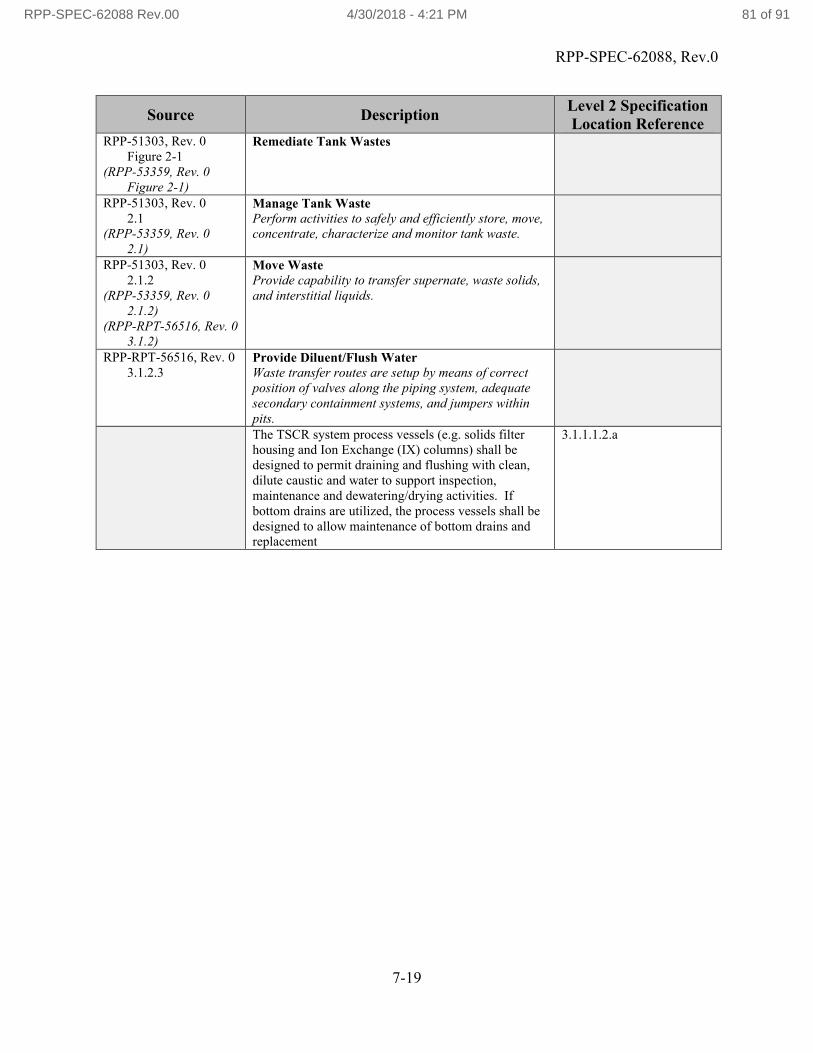
RPP-SPEC-62088, Rev.0
7-19
Source DescriptionLevel 2 Specification Location Reference
RPP-51303, Rev. 0Figure 2-1
(RPP-53359, Rev. 0Figure 2-1)
Remediate Tank Wastes
RPP-51303, Rev. 02.1
(RPP-53359, Rev. 02.1)
Manage Tank WastePerform activities to safely and efficiently store, move, concentrate, characterize and monitor tank waste.
RPP-51303, Rev. 02.1.2
(RPP-53359, Rev. 02.1.2)
(RPP-RPT-56516, Rev. 03.1.2)
Move WasteProvide capability to transfer supernate, waste solids, and interstitial liquids.
RPP-RPT-56516, Rev. 03.1.2.3
Provide Diluent/Flush WaterWaste transfer routes are setup by means of correct position of valves along the piping system, adequate secondary containment systems, and jumpers within pits.The TSCR system process vessels (e.g. solids filter housing and Ion Exchange (IX) columns) shall be designed to permit draining and flushing with clean, dilute caustic and water to support inspection, maintenance and dewatering/drying activities. If bottom drains are utilized, the process vessels shall be designed to allow maintenance of bottom drains and replacement
3.1.1.1.2.a
RPP-SPEC-62088 Rev.00 4/30/2018 - 4:21 PM 81 of 91

RPP-SPEC-62088, Rev.0
7-20
Source DescriptionLevel 2 Specification Location Reference
RPP-51303, Rev. 0Figure 2-1
(RPP-53359, Rev. 0Figure 2-1)
Remediate Tank Wastes
RPP-51303, Rev. 02.1
(RPP-53359, Rev. 02.1)
Manage Tank WastePerform activities to safely and efficiently store, move, concentrate, characterize and monitor tank waste.
RPP-51303, Rev. 02.1.2
(RPP-53359, Rev. 02.1.2)
(RPP-RPT-56516, Rev. 03.1.2)
Move WasteProvide capability to transfer supernate, waste solids, and interstitial liquids.
RPP-RPT-56516, Rev. 03.1.2.4
Control Parameters During TransferWaste transfer routes are setup by means of correct position of valves along the piping system, adequate secondary containment systems, and jumpers within pits.The TSCR system shall be designed to receive waste with the estimated radiological, chemical, and physical properties as defined through sub-tier specifications.
3.1.1.1.3.a
RPP-SPEC-62088 Rev.00 4/30/2018 - 4:21 PM 82 of 91
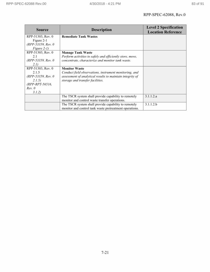
RPP-SPEC-62088, Rev.0
7-21
Source DescriptionLevel 2 Specification Location Reference
RPP-51303, Rev. 0Figure 2-1
(RPP-53359, Rev. 0Figure 2-1)
Remediate Tank Wastes
RPP-51303, Rev. 02.1
(RPP-53359, Rev. 02.1)
Manage Tank WastePerform activities to safely and efficiently store, move, concentrate, characterize and monitor tank waste.
RPP-51303, Rev. 02.1.5
(RPP-53359, Rev. 02.1.5)
(RPP-RPT-56516, Rev. 0
3.1.2)
Monitor WasteConduct field observations, instrument monitoring, and assessment of analytical results to maintain integrity of storage and transfer facilities.
The TSCR system shall provide capability to remotely monitor and control waste transfer operations.
3.1.1.2.a
The TSCR system shall provide capability to remotely monitor and control tank waste pretreatment operations.
3.1.1.2.b
RPP-SPEC-62088 Rev.00 4/30/2018 - 4:21 PM 83 of 91

RPP-SPEC-62088, Rev.0
7-22
Source DescriptionLevel 2 Specification Location Reference
RPP-51303, Rev. 0Figure 2-1
(RPP-53359, Rev. 0Figure 2-1)
Remediate Tank Wastes
RPP-51303, Rev. 02.1
(RPP-53359, Rev. 02.1)
Manage Tank WastePerform activities to safely and efficiently store, move, concentrate, characterize and monitor tank waste.
RPP-51303, Rev. 02.1.5
(RPP-53359, Rev. 02.1.5)
(RPP-RPT-56516, Rev. 0
3.1.2)
Monitor WasteConduct field observations, instrument monitoring, and assessment of analytical results to maintain integrity of storage and transfer facilities.
RPP-RPT-56516, Rev. 0
3.1.5.1.
Monitor Tank Integrity Required to verify the integrity of the tanks.
At a minimum, TSCR monitoring of waste storageoperations shall include the capability to monitor secondary containment leak detector signals.
3.1.1.2.1.a
At a minimum, monitoring of waste transfer operations through the TSCR system shall include encasement piping leak detector signals.
3.1.1.2.1.b
RPP-SPEC-62088 Rev.00 4/30/2018 - 4:21 PM 84 of 91

RPP-SPEC-62088, Rev.0
7-23
Source DescriptionLevel 2 Specification Location Reference
RPP-51303, Rev. 0Figure 2-1
(RPP-53359, Rev. 0Figure 2-1)
Remediate Tank Wastes
RPP-51303, Rev. 02.1
(RPP-53359, Rev. 02.1)
Manage Tank WastePerform activities to safely and efficiently store, move, concentrate, characterize and monitor tank waste.
RPP-51303, Rev. 02.1.5
(RPP-53359, Rev. 02.1.5)
(RPP-RPT-56516, Rev. 0
3.1.2)
Monitor WasteConduct field observations, instrument monitoring, and assessment of analytical results to maintain integrity of storage and transfer facilities.
RPP-RPT-56516, Rev. 0
3.1.5.2.
Monitor Tank PropertiesRequired to verify the process conditions.
At a minimum, TSCR monitoring of waste storage operations may include the following capabilities
Tank liquid level
Tank liquid temperature
Tank inlet valve interlock for level High-High
Sump level High-High
Tank pressure (vacuum), or if impractical due to system design, Tank Ventilation Flow
3.1.1.2.2.a
At a minimum, monitoring of waste transfer operations for the TSCR system may include the following capabilities
Transfer pump transfer permissive interlock
Pump start/stop command
Source tank liquid level
Transfer pump pressure
Transfer pump flow rate
Transfer pump power consumption
Transfer pump interlock for source tank level Low-Low
Transfer pump interlock for pump pressure High-High
3.1.1.2.2.b
RPP-SPEC-62088 Rev.00 4/30/2018 - 4:21 PM 85 of 91

RPP-SPEC-62088, Rev.0
7-24
Source DescriptionLevel 2 Specification Location Reference
RPP-51303, Rev. 0Figure 2-1
(RPP-53359, Rev. 0Figure 2-1)
Remediate Tank Wastes
RPP-51303, Rev. 02.3
(RPP-53359, Rev. 02.3)
Process Tank WasteProcess tank waste retrieved from DSTs, SSTs, and ancillary storage systems and convert HLW, LAW and potential CH-TRU tank waste into waste forms suitable for disposal in compliance with applicable federal, state,and local requirements, including environmental permits and other regulatory approvals and authorizations.
RPP-51303, Rev. 02.3
(RPP-53359, Rev. 02.3)
(RPP-RPT-56516, Rev. 0
2.3.1)
Pretreat WasteReceive both HLW feed and LAW feed from the DST system; concentrate dilute waste; separatesolids from liquid phases; perform caustic and oxidative leaching, as needed, to enhance processing efficiency; separate waste streams into a HLW fraction and a LAW fraction; transfer the HLW and LAW feeds to the appropriate immobilization facility; and receive and process recycle streams.The TSCR design shall be based on a range of values for specific parameters considered important to the TSCR process as defined through sub-tier specification details.
3.1.2.1.a
RPP-SPEC-62088 Rev.00 4/30/2018 - 4:21 PM 86 of 91

RPP-SPEC-62088, Rev.0
7-25
Source DescriptionLevel 2 Specification Location Reference
RPP-51303, Rev. 0Figure 2-1
(RPP-53359, Rev. 0Figure 2-1)
Remediate Tank Wastes
RPP-51303, Rev. 02.3
(RPP-53359, Rev. 02.3)
Process Tank WasteProcess tank waste retrieved from DSTs, SSTs, and ancillary storage systems and convert HLW, LAW and potential CH-TRU tank waste into waste forms suitable for disposal in compliance with applicable federal, state, and local requirements, including environmental permits and other regulatory approvals and authorizations.
RPP-51303, Rev. 02.3
(RPP-53359, Rev. 02.3)
(RPP-RPT-56516, Rev. 0
2.3.1)
Pretreat WasteReceive both HLW feed and LAW feed from the DST system; concentrate dilute waste; separate solids from liquid phases; perform caustic and oxidative leaching, as needed, to enhance processing efficiency; separate waste streams into a HLW fraction and a LAW fraction; transfer the HLW and LAW feeds to the appropriate immobilization facility; and receive and process recycle streams.
RPP-RPT-56516, Rev. 0
3.3.1.3
Remove Constituents from LAWConstituents are removed as required to ensure compliance with the LAW waste acceptance criteria. Removal of constituents from LAW comprises.The TSCR system shall be capable of removing undissolved solids from tank supernatant waste.
3.1.2.1.1.a
The TSCR system shall be capable of selectively removing Cs from filtered waste through the use of a non-elutable ion exchange resin to meet the ICD-30 waste acceptance criteria Cs ratio limitation of <3.18 E-5 Ci/mol sodium.
3.1.2.1.1.b
Reserved. 3.1.2.1.1.c
RPP-SPEC-62088 Rev.00 4/30/2018 - 4:21 PM 87 of 91

RPP-SPEC-62088, Rev.0
7-26
Source DescriptionLevel 2 Specification Location Reference
RPP-51303, Rev. 0Figure 2-1
(RPP-53359, Rev. 0Figure 2-1)
Remediate Tank Wastes
RPP-51303, Rev. 02.4
(RPP-53359, Rev. 02.4)
Dispose Tank WasteDispose secondary waste onsite in compliance with regulatory requirements and disposal facility waste acceptancecriteria.
RPP-51303, Rev. 02.4.4
(RPP-53359, Rev. 02.4.4)
(RPP-RPT-56516, Rev. 0
3.1.2)
Dispose Secondary WasteAccept secondary wastes generated by the MANAGE TANK WASTE, RETRIEVE TANK WASTE, and PROCESS TANK WASTE functions, dispose in a permitted disposal facility, or discharge treated effluents to the environment.
RPP-RPT-56516, Rev. 0
3.4.2.2
Dispose Gaseous EffluentsGaseous effluents will be treated at the respective tanks or processing facilities for compliance with Hanford air permits and released to the atmosphere.The ventilation system shall control radioactive airborne emissions in compliance with the requirements of WAC 246-247, Radiation Protection – Air Emissions; AOP 00-05-006, Hanford Site Air Operating Permit 00 05 006; TFC-ESHQ-ENV-STD-03, “Air Quality – Radioactive Emissions”; TFC-ESHQ-ENV-STD-11, “Air Program Plan”; RPP-16922, “Tank Farm Environmental Requirements”; and TFC-ENG-STD-07, “Ventilation System Design Standard.”
3.1.3.1.1.a
The ventilation system shall control non-radioactive airborne emissions in compliance with the requirements of 40 CFR 61, National Emission Standards for Hazardous Air Pollutants and WAC 173-400, General Regulations for Air Pollution Sources, as implemented by TFC-ESHQ-ENV-STD-04, “Air Quality Program –Non-Radioactive Emissions” (Section 3.3.3.1 only); TFC-ESHQ-ENV-STD-11; and TFC-ENG-STD-07.If the TSCR ventilation system is deemed necessary, the ventilation system shall provide capability to sample radioactive emissions in compliance with ANSI/HPS N13.1, Sampling and Monitoring Releases of Airborne Radioactive Substances from the Stacks and Ducts of Nuclear Facilities; TFC-ESHQ-ENV-STD-05, “Radioactive Airborne Effluent Sampling” and TFC-ESHQ-ENV-STD-11.”
3.1.3.1.1.c
RPP-SPEC-62088 Rev.00 4/30/2018 - 4:21 PM 88 of 91

RPP-SPEC-62088, Rev.0
7-27
Source DescriptionLevel 2 Specification Location Reference
RPP-51303, Rev. 0Figure 2-1
(RPP-53359, Rev. 0Figure 2-1)
Remediate Tank Wastes
RPP-51303, Rev. 02.5
(RPP-53359, Rev. 02.5)
Manage System-Generated Tank WastePrepare and certify system-generated waste for transfer to interfacing disposal facilities; closetanks, tank farms, ancillary facilities and associated waste management areas; and deactivate, isolate, and close excess facilities and processing facilities.
RPP-51303, Rev. 02.5.4
(RPP-53359, Rev. 02.5.4)
(RPP-RPT-56516, Rev. 0
3.5.4)
Manage Secondary WasteTreat gaseous effluents generated during RPP mission operations for release to the atmosphere. Prepare liquid and solid secondary wastes generated during RPP mission operations to meet on-site disposal facility waste acceptance criteria.
RPP-RPT-56516, Rev. 0
3.5.4.1
Manage Secondary Solid WasteThe purpose of secondary solid waste management is to package the solid waste suitable for disposal (after any required treatment), and to transport the packages to the disposal site. Secondary waste that meets the waste acceptance criteria for Hanford solid waste will be disposed onsite.The TSCR system shall include design features to move secondary solid waste packages containing spent ion-exchange media for transfer to a permitted interim storage pad.The TSCR system shall be capable of transferring backwashed filtered solids to the DST system in accordance with TFC-ENG-STD-26.
RPP-SPEC-62088 Rev.00 4/30/2018 - 4:21 PM 89 of 91

RPP-SPEC-62088, Rev.0
7-28
Source DescriptionLevel 2 Specification Location Reference
RPP-51303, Rev. 0Figure 2-1
(RPP-53359, Rev. 0Figure 2-1)
Remediate Tank Wastes
RPP-51303, Rev. 02.5
(RPP-53359, Rev. 02.5)
Manage System-Generated Tank WastePrepare and certify system-generated waste for transfer to interfacing disposal facilities; closetanks, tank farms, ancillary facilities and associated waste management areas; and deactivate, isolate, and close excess facilities and processing facilities.
RPP-51303, Rev. 02.5.4
(RPP-53359, Rev. 02.5.4)
(RPP-RPT-56516, Rev. 0
3.5.4)
Manage Secondary WasteTreat gaseous effluents generated during RPP mission operations for release to the atmosphere. Prepare liquid and solid secondary wastes generated during RPP mission operations to meet on-site disposal facility waste acceptance criteria.
RPP-RPT-56516, Rev. 0
3.5.4.3
Manage Secondary Liquid Effluent The purpose of liquid effluents management is to treat secondary liquid effluents to meet compliance with regulatory requirements prior to disposal.The TSCR system shall be capable of transferring all system generated liquid waste back to the DST system.
3.1.4.1.2.a
The TSCR system shall have the capability to flush the transfer lines and valves to the DST system in compliance with the requirements of TFC-ENG-STD-26.
3.1.4.1.2.b
RPP-SPEC-62088 Rev.00 4/30/2018 - 4:21 PM 90 of 91

RPP-SPEC-62088, Rev.0
7-29
Source DescriptionLevel 2 Specification Location Reference
RPP-51303, Rev. 0Figure 2-1
(RPP-53359, Rev. 0Figure 2-1)
Remediate Tank Wastes
RPP-51303, Rev. 02.5
(RPP-53359, Rev. 02.5)
Manage System-Generated Tank WastePrepare and certify system-generated waste for transfer to interfacing disposal facilities; close tanks, tank farms, ancillary facilities and associated waste management areas; and deactivate, isolate, and close excess facilities and processing facilities.
RPP-51303, Rev. 02.5.5
(RPP-53359, Rev. 02.5.5)
(RPP-RPT-56516, Rev. 0
3.5.5)
Close Tanks, Waste Management Areas and Excess FacilitiesDeactivate and isolate ancillary equipment and transfer structures, as well as deactivate,decontaminate, decommission, and demolish tank farm structures, treatment facilities, andancillary structures used during the tank-waste remediation mission.The TSCR system shall include design features which simplify decontamination and facilitate decommissioning at facility end-of-life in compliance with the requirements of DOE O 420.1C, Facility Safety [Chapter 1, 3.b. (4) (a)]
3.1.4.2.a
The design or modification of the TSCR system and the selection of materials shall include features that facilitate operations, maintenance, decontamination, and decommissioning. [10 CFR 835.1002 (d), Occupational Radiation Protection Subpart K – Design and Control, Paragraph 835.1002, Facility design and modifications].
3.1.4.2.b
RPP-SPEC-62088 Rev.00 4/30/2018 - 4:21 PM 91 of 91