Embed Size (px)
Citation preview
Date : 06/15/2016
EIC Detector R&D Progress Report
Project ID: eRD15Project Name : R&D for a Compton Electron DetectorPeriod Reported: from 01/15/2016 to 06/15/2016Project Leader : Alexandre CamsonneContact Person : Alexandre Camsonne
Abstract
Precision polarimetry is an important component for the EIC. It aims at reaching 1% level precision.Compton Polarimetry is commonly use for electron polarimetry. It allows a non invasive measurement ofthe electron polarization. Accuracies up to 0.52% were achieved using the Compton Electron detection.Sub-percent precision is foreseeable for EIC though the significantly higher current and space constraintsrequire an extensive study. This proposal is looking at the option of a semi-conductor detector in aRoman Pot chamber to detect the Compton electrons.
1

EIC Detector R&D Progress Report
Alexandre Camsonne1, Dipankgar Dutta4, Michael Sullivan5, David Gaskell1,Cynthia Keppel1, Fanglei Lin1, Juliette Mammei2, Joshua Hoskins2, Michael J.
Murray3, Christophe Royon3, Nicola Minafra3, Vasiliy Morozov1, Haipeng Wang1,and Robert Rimmer1
1 Thomas Jefferson National Accelerator Facility2 University of Manitoba
3 Kansas University4 Mississipi State University
5 SLAC National Accelerator Laboratory
June 15, 2016
1 Progress Report Section
1.1 Past
1.1.1 What was planned for this period?
Here is the list of task from the previous report :
• Completion of the first pass beamline design of the Compton
• Study of background and detector response.
• Design of the test stand.
• Contact the TOTEM collaboration.
From last report : “The collaboration reported on the preparation of the simulation framework forthe Compton polarimeters electron detector in the EIC lattice. The GEMC framework using GEANT4and developed for CLAS12 at JLab was employed. The design discussed includes a Compton chicaneincluding beam pipe. Testing of the simulation framework has begun, and manpower to pursue theeffort has been identified and engaged. The collaboration is taking into account the significant differencein expected rates between the eRHIC and JLEIC designs. The collaborators have made contact withthe CLAS12 SVT effort with their local wire bonding expertise with a view towards future studiesof timing response of possible detectors including diamond based devices. The Committee takes noteof the planned contact with results from existing Compton polarimeters in operation, for example, atJLab and elsewhere. The collaboration plans a revised scattering chamber to enable in-beam tests ofcandidate detectors, their time response and their electronics. The Committee looks forward to the nextreport where first simulation results are expected and to the resulting discussion of machine backgroundsand interfaces as well as to a discussion of radiation damage to any sensor and the power deposited in adetector and its infrastructure by backgrounds. An interesting discussion would address required amountof shielding and any limitations on laser power and thus counting rate that may result, and the effecton measurement strategy, time and precision. Continued contact with the accelerator groups developingthe two machine reference designs is encouraged.”
1.1.2 What was achieved ?
Preliminary design of the test stand was completed. The cost of the lower chamber is more accuratelydefined and is ready to be built. Contact with Kansas University was very fruitful. Their experience withRoman Pots at LHC and detectors will be very useful for the development of the Compton Polarimeter.
2
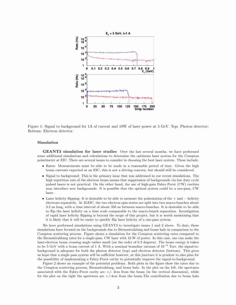
Figure 1: Signal to background for 1A of current and 10W of laser power at 5 GeV. Top: Photon detector;Bottom: Electron detector.
Simulation
GEANT3 simulation for laser studies Over the last several months, we have performedsome additional simulations and calculations to determine the optimum laser system for the Comptonpolarimeter at EIC. There are several issues to consider in choosing the best laser system. These include:
• Rates: Measurements must be able to be made in a reasonable period of time. Given the highbeam currents expected at an EIC, this is not a driving concern, but should still be considered.
• Signal to background: This is the primary issue that was addressed in our recent simulations. Thehigh repetition rate of the electron beam means that suppression of backgrounds via low duty cyclepulsed lasers is not practical. On the other hand, the use of high-gain Fabry-Perot (CW) cavitiesmay introduce new backgrounds. It is possible that the optimal system could be a one-pass, CWlaser.
• Laser helicity flipping: It is desirable to be able to measure the polarization of the + and − helicityelectrons separately. At JLEIC, the two electron spin states are split into two macro-bunches about3.2 us long, with a time interval of about 350 ns between macro-bunches. It is desirable to be ableto flip the laser helicity on a time scale comparable to the macro-bunch separation. Investigationof rapid laser helicity flipping is beyond the scope of this project, but it is worth mentioning thatit is likely that it will be easier to quickly flip laser helicity of a one-pass system.
We have performed simulations using GEANT3 to investigate issues 1 and 2 above. To date, thesesimulations have focused on the backgrounds due to Bremsstrahlung and beam halo in comparison to theCompton scattering process. Figure shows a simulation for the Compton scattering rates compared tothe Bremsstrahlung rates for a single-pass, CW laser with 10 W of power. In this case, one can make thelaser-electron beam crossing angle rather small (on the order of 0.3 degrees). The beam energy is takento be 5 GeV with a beam current of 1 A. With a nominal beamline vacuum of 10−9 Torr, the signal-to-background is adequate for both the photon detector (top) and electron detector (bottom). This givesus hope that a single pass system will be sufficient however, at this juncture it is prudent to also plan forthe possibility of implementing a Fabry-Perot cavity to potentially improve the signal-to-background.
Figure 2 shows an example of the potential problems. Both plots in the figure show the rates due tothe Compton scattering process, Bremsstrahlung, and beam halo. In the plot on the left, the aperturesassociated with the Fabry-Perot cavity are +/- 2cm from the beam (in the vertical dimension), whilefor the plot on the right the apertures are +/-4cm from the beam.The contribution due to beam halo
3

Figure 2: Geant3 simulated rates in the photon detector (top) and electron detector (bottom) for Comptonbackscattering (blue curve) and Bremsstrahlung (red curve). The beamline vacuum is taken to be 10−9 Torrwith a beam energy/current of 5 GeV/1 A. The electron detector spectrum is plotted vs. strip number in thiscase strip 25 corresponds to the zero-crossing of the asymmetry (about 2 cm from the beam for our layout).In the implementation of a Fabry-Perot cavity, care must be taken to not introduce additional backgroundsin the form of the interaction of the beam halo with the additional elements and apertures required for themirror holders associated with the low-loss mirrors needed for the cavity.
4

Table 1: Event rates and measurement times (for 1% statistics) for the single-pass and Fabry-Perot cavitylaser options. The rates are adequate for both solutions assuming negligible backgrounds. The CW lasersolution assumes a 10 W laser with a crossing angle of 0.3 degrees, while the Fabry-Perot cavity systemassumes 1 kW at a crossing angle of 2.6 degrees. A fixed polarization of 87% was assumed for the polarizationmeasurement time calculations. This is not necessarily realistic for all energies, however is appropriate forthe order-of-magnitude estimates shown here.
is almost completely absent for the wider aperture. The key point here is that it is important to havesome realistic estimate of the beam halo, and carefully design the Fabry-Perot cavity accordingly. It isalso worth noting that increasing the aperture for the Fabry-Perot cavity implies that the cavity mustbe longer to achieve the same beam-laser crossing angle. We have done the simple exercise that shows astable cavity with a reasonable 2-meter length can be built that will accommodate the +/-4 cm apertureused in our simulations.Figure 2: Simulated rates for different Fabry-Perot cavity geometries. The redand blue curves are as in Figure 1.1.2, while the magenta curves denote the rates due to beam halointeracting with the mirror apertures associated with the Fabry-Perot cavity. For the plot on the left,the apertures are +/-2 cm from the beam, while on the right they are +/-4cm from the beam. TheFabry-Perot cavity is assumed to provide 1kW of CW power at a crossing angle of 2.6 degrees.Finally,we have calculated to absolute rates and measurement times (for a 1% statistical measurement of thepolarization) for both the single-pass laser solution shown in Figure 1.1.2 and the Fabry-Perot cavitysolution shown in Figure 2 (Table 1). In this case, the rates and times are integrated over the fullCompton spectrum and assume that the measurement is made in counting mode (as opposed to energy-integrated mode, for example). These estimates come not from the GEANT3 simulation, but from ananalytical calculation of the luminosity and Compton cross section. Also, no backgrounds are included,so measurement times would likely be slightly longer for the real-world scenario.From Table 1 we cansee that the rate of Compton backscattered events is greater than 1 MHz for all the energies considered(beam currents associated with this energies are the maximum allowed by the JLEIC design). Theassociated measurement times are also quite short, on the order of 100-300 ms. If there were no concernfor beam-related backgrounds, the single-pass system would be an adequate option with the advantageof simpler implementation. The event rate for the Fabry-Perot cavity laser option is on the order of afactor of 10 larger (even though the power is 100 times larger, some rate is lost due to the larger crossingangle that is required). In conclusion, we have shown that both a single-pass laser and Fabry-Perotcavity-based laser system are both feasible options for the Compton polarimeter at JLEIC. The finalchoice will likely not be made until the full background simulations using the improved GEANT4 basedpackage are complete.
GEMC (GEANT4) simulation
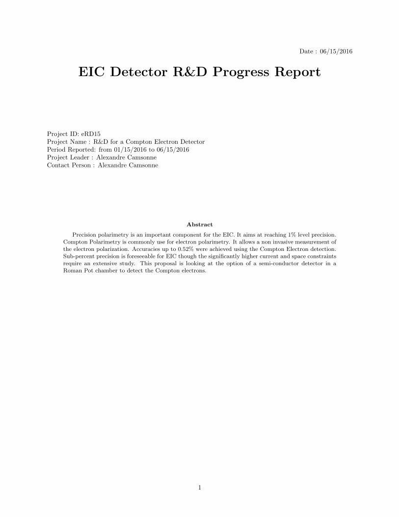
Beamline geometry The first months of the current project year were dedicated to implementingthe beamline geometry as shown on Fig. 3 and Fig. 4. Simple beam pipe is implemented, there is stillrefinement in the design needed and some work on implementing the magnetic field.
Simulation of background The second step was the study of the background coming fromthe beam which can be a significant rate in the detector since the electron current can reach up to 3A.Electrons were transported in the chicane and the rates in the electron detector are shown in Figure 5.
Simulation with the Compton Event generator The rest of the time was spent on theevent generation and simulation in GEANT4. We reused the event generator from Richard Petti from
5
Figure 3: GEMC model of the beamline and of the Compton chicane.
Figure 4: Close-up of the electron detector in front of the fourth dipole – the electrons are momentumanalyzed by the third dipole.
6
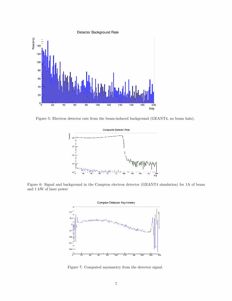
Figure 5: Electron detector rate from the beam-induced background (GEANT4, no beam halo).
Figure 6: Signal and background in the Compton electron detector (GEANT4 simulation) for 1A of beamand 1 kW of laser power
Figure 7: Computed asymmetry from the detector signal.
7

0 20 40 60 80 100 120 140 160 180 2000.15−
0.1−
0.05−
0
0.05
0.1
Compton Asymmetry
No window
m windowµ500
Figure 8: Compton asymmetry with and without a 500 µm thin steel window in front of the detector.
Figure 9: Compton dose deposition per hour.
the eRD12 to generate Compton events. We crosschecked the rates and asymmetry with the Geant3and theoretical computation. Preliminary results of the expected background and expected signal givesa first idea of the signal to background ratio for this design. The results for signal and backgroundrates in the electron detector with the GEANT4 simulation are shown in Figure 6. The signal to noiseis consistent with the GEANT3 simulation and so far not taking into account additionnal backgroundfrom the beamline and the interaction region, 10 W of laser power is sufficient. The projected Comptonasymmetry is shown in Figure 7. An interesting feature of Figure 6. is that there are ’signal electrons’beyond the Compton edge (higher strip number ⇒ lower energies). This is the result of a fraction of theCompton scattered electrons rescattering before the detector. This could potentially distort the shapeof the asymmetry in Figure 7.
Figure 8 shows the result of our study of the effect of window in front of the electron detector.The Roman Pot thin windows introduces 500 µm of steel in front of the detector. The plot with andwithout without are similar within statistical fluctuations. Study with higher statistics and with the fullpolarization extraction analysis will be done to study the incurred systematic error on polarization.
Preliminary dose estimate Since the simulation is running, we computed an estimate of dosedeposited (Figure 9). This shows that most of the radiation damage is still coming from the Comptonsignal and the rest of the radiation is fairly low meaning we can safely leave the detector in place andturn off the laser to have a lower duty cycle. From the running experience from the Hall C QWeakexperiment, the diamond detector saw no deterioration of signal after 2 years of running at 180 µAwhich corresponded to more than 10 Mrad of dose. This corresponds to 570 rad per hour at 180 µAwhich gives a value of around 10 MRad per hour. The simulation is giving a number of about 90 kRadper hour per strip, which correspond to about 10 MRad per hour for the whole detector which is closeto estimated number. More accurate crosschecks and measurements will be done to check the simulation
8

Figure 10: Simple CAD model of Roman Pot
calibration later. Looking at the polarization lifetime of a few hours at the lowest energy and highestcurrent of 3A a polarization measurement every 10 minutes should be sufficient. Measurement can bemade more often at the highest energy where polarization lifetime is shorter but beam current will belower at 0.7 A. A radiation hard detector is desirable and diamond is a good candidate.
Wakefield estimate The Compton electrons are separated from the main beam by up to 7 cmat the location of the detector. In order to have the best systematic errors, we must catch both the zerocrossing of the asymmetry and the Compton edge. This well make the detector self-calibrating, and willeliminate many systematics, particularly due to the detector positioning. For most energies it means thedetector needs to be one to two centimeter from the beam. For a safe beam operation nothing closerthan 3 cm from the beam is advised when beam is being tuned which make the design of a thin windowdifficult considering how close it would be from the beam. The best compromise is a moving detectorwhich could be inserted close to be beam for the polarization measurement. Such detector is in operationat Jefferson Laboratory though with the expected EIC current ( 50 mA and up to 3 A ) an estimation ofthe power deposited by the Wakefield from the beam is needed. Since the detector will most likely needto be shielded and to have more flexibility in accessing the detector a Roman Pot design is envisionnedfor the Compton electron detector. This would be the first time the roman pot technique is being usedfor an electron beam. We are planning to replicate the same study as it was done for the TOTEM [1]roman pots.
Our collaborators from SLAC have the machinery to study Wakefield Higher Order Modes, thoughin order to speed up the process of optimization the detector geometry to reduce the impedance of thedetector which will require several iterations we also looked at local expertise from the JLab RF group.
A first simple design has been implemented to give a baseline of the RF power deposited. Numbersfrom the TOTEM collaboration are encouraging since a value of 10 W was reached but the study needsto be redone with the beam structure of JLEIC ( 476 MHz ). For PEPII which had a smaller bunchlength values up to 2 kW were reached for some of the collimators. The model could be imported toCST Particle Studio, available at JLab. Preliminary results will be presented at the next report.
1.2 Vacuum chamber
The goal of the test stand is to make the current Hall A and C Compton polarimeters compatible withnew detectors for testing potential candidates for the EIC Compton electron detector while also beingcompatible with the existing detectors in Hall A and Hall C. This will enable testing of existing siliconand diamond detectors, as well as new detectors and electronics, which could be carried out in either hall,
9

Figure 11: Simple CAD model of Roman Pot inside view
improving the availability of the setup. The Jefferson Laboratory Compton polarimeters have alreadybeen proven to be capable of providing polarization measurement at the 1% level, this will be a wayto benchmark the performance of the detector. The design of the test stand is based on the Hall Celectron detector design which was used successfully for the diamond detector. A preliminary design ofthe chamber was done to get a cost estimate which is close to the requested number last year.
Figure 12: Design of lower chamber
1.2.1 What was not achieved, why not, and what will be done to correct ?
We ran out of time to completely address all the requests from the last committee report, we are stillworking on checking the normalization and optimizing the event generator for more efficient simulation.
10

• Study of effect of bunch interacting with same bunch or different bunch is on hold waiting forresults of the beam simulation (currently underway at ODU). Preliminary result of the possibilityof different numbers of electron and ions bunches should be available by the end of 2016
• Background from the IR was not done yet mostly due to computing power and running the differentphysics process of the IR
• Study of the systematics will be done after the polarization extraction analysis is implemented
• Synchrotron radiation
• Wakefield power deposition in detector
A few technical items where we lost time :
• The study of the photon detector response to crosscheck with the old Geant3 simulation but contraryto electrons the primary particle is lost for a photon and handling of the secondaries to determineenergy deposit was not clear. This is better documented in the Monte Carlo documentation.
• A study to improve the Bremsstrahlung efficiency generation was done, typically one can scale theair pressure in the beam pipe to generate more Bremsstrahlung event, though the study showedthat going above atmospheric pressure was giving rates non linear with the pressure most likelydue to other processes.
• The option to add custom physics list to GEMC needs to be developed.
We expect the studies to go faster now that the postdoc (Joshua Hoskins) is set up and familiar withthe simulation and data analysis and that results were crosschecked with the GEANT3 simulation. Themain issue is to run the full setup in the simulation on the JLab batch-farm to produce high statisticsUp to now to make rapid progress the simulations were done only with the Compton chicane part.
Complete design of the chamber was not completed due to lack of designer time this year due toexperimental schedule constraints, the money allotted will be carried over and used next year. Availabilityof the designer next year was agreed upon.
The option to test the detector with the CLAS12 preamp was discussed but it is postponed to nextyear due to time constraints to complete the CLAS12 Silicon Vertex Tracker this year.
1.3 Future
1.3.1 What is planned for the next funding cycle and beyond ? How, if at all, isthis planning different from the original plan ?
For next funding cycle we are planning to continue the simulation work to have numbers on the signalto noise background and expected accuracy from the detector with a more realistic setup. We willimplement the current electron detector analysis software to study the systematics introduced on thepolarimetry measurement. Estimates for power and radiation damage will be evaluated after we crosscheck the normalization of the simulation. Model of the halo of the beam will be added to evaluate thecontribution of this background. Bench test of the TOTEM electronics will be done to determine if thedetector or electronics is the main limitation to a short pulse width, the TOTEM detectors seem to fullfillthe timing requirements, the main developement will be how to handle the Compton trigger rates. Thiswill be more developed in the proposal section. The lower chamber will be sent to be built and will beused as shielding for the bench tests. The design of the top chamber will be finalized to be procured atthe next funding cycle, we would like to carry the previous funding to the following year.
1.3.2 What are the critical issues ?
The main critical issues to be addresses by this proposal :
• determine the signal to background expected on which depends the choice of the photon source anddetector
• have a preliminary design for the beamline for the JLEIC design based on Roman Pot. Afterdiscussion the eRHIC people it seems this design might also work for eRHIC but is more difficultthan for protons and would need to be studied in depth. The current option for eRHIC is an exitwindow which might be easier to implement than in the JLEIC design due to different magnetconfigurations.
• obtain a detector with a timing response faster than 100 ns, to be able to separate the differentsources of eRHIC in the case the ring linac design
11

• have simulation and analysis to estimate the expected accuracy of polarization measurement for agiven design
• determine if background from IR is an issue for the JLEIC design where the polarimeter is placedafter the IR
• develop a beam test stand in the current subpercent capabable Compton Polarimeter to prove thatthe chosen detector reaches the needed specifications and does not introduce systematics preventingto reach 1% accuracy level.
1.4 Manpower
Manpower estimates for 2016Personnel % FTE location tasks
Alexandre Camsonne 20 JLab General organization,Wakefield studies, postdoc supervisionDavid Gaskell 5 JLab Geant3, Laser system, postdoc supervision
Joshua Hoskins 50 JLab GEMC simulation and data analysis
Planned manpower for 2017. We are welcoming the Kansas University group to help on the electronicsand detector.
Personnel % FTE location tasks
Alexandre Camsonne 20 JLab General organization,Wakefield studies, postdoc supervisionDavid Gaskell 5 JLab Geant3, Laser system, postdoc supervision
Joshua Hoskins 50 JLab GEMC simulation and data analysisMichael J. Murray 5 Kansas University detector, electronicsChristophe Royon 5 Kansas University detector, electronics
Nicola Minafra 5 Kansas University Wakefield and amplifier designIn addition to the core manpower, Michael Sullivan from SLAC is advising on Synchrotron Radiation,
Robert Rimmer and Haipeng Wang from JLab RF group are advising about Wakefield HOM modelling.
1.5 External funding
None
1.6 Publications
The work on the EIC R&D Compton Electron Detector was presented at the POETIC 6 conference anda proceeding was published.
2 Proposal
2.1 Proposal deliverables
This year proposal is planning to complete the studies started in the first year.
• implement simulation on the farm and run with the full detector setup to determine background inthe detector from the interaction point
• complete beamline pipe in simulation to look a background contribution from the pipe
• implement beam halo in simulation
• implement polarization analysis and study the systematics
• complete the wakefield simulation to have a first estimate of the power deposit in the detector todetermine if Roman Pot design is doable for the electron side
• study of synchrotron radiation effect in the detector
• reduce background and protect detector through shielding
• study of effect of shielding on measurement
• show TOTEM detector can reach less than 100 ns pulse width making it compatible with eRHICbeam structure
12

• design of multichannel amplifier to amplify diamond or silicon signal possibly on the detector
• design of multichannel discriminator board for readout of all the detector channels
• complete design of test stand for beam test
3 Simulation and modeling
3.1 Beam halo implementation for background study
The next step is to look at the background contribution from halo. We will be using a double gaussiandistribution as described in the PEPII report:
dN
dxdy= e
− x2
2σ2x− y2
2σ2y +Ae− x2
2(Sxσx)2− y2
2(Syσy)2 (1)
This background can be significant, especially when there are close apertures that could be needed if anoptical cavity is used.
Task Time estimate
Implement Halo 1 monthSimulation full setup 2 monthImplement analysis 1 month
Study of systematics and background 6 months
3.2 Analysis
We have analysis code that were used for polarimetry measurement during the QWeak experiment [2].We will get the analysis scripts and adapt to the EIC simulation to extract a polarization from pseudodata. It consists in fitting the measured asymmetry with the theoretical analysing power to extract thepolarization.
3.3 Wakefield Evaluation and Roman Pot Design
First result from the simple design will be generated to determine if the roman pot option is reasonable infirst approximation. A more realistic design of the roman pot will be done to optimize the impedance. Afew design iterations and CST simulation will be needed. The power spectrum of JLEIC and impedanceof the setup needs to be simulated to give the first evaluation of the power deposit in the detector. Thiswork will be done in collaboration with the Kansas University group and the JLab SRF group. Oncepower from wakefield is determined modelling in ANSY can be done to determine the heat distributionand design the cooling.
3.4 Synchrotron radiation estimation
Even if the Compton Electron Detector is in a favorable position compared to the photon detector,at 3 A of beam current synchrotron radiation will be an issue and needs to be studied. Synchrotronradiation can results in electrons from the beam going into the detector and of photons hitting thedetector directly or after reflections. Michael Sullivan from SLAC has experience with the PEPII andwill help in evaluating the synchrotron radiation for the electron detector and way to mitigate them usingshielding and absorbers. He will be visiting at the end of June. This study will be completed in the nextyear crosschecking the simulation results analytic formulas.
4 Test stand
4.1 Vacuum chamber
Design of the top chamber will be completed after the front end is designed to take into account thespace taken by the new electronics and the use of the connectors matching the electronics. Designer timehas been allocated at JLab.
13

4.2 Bench detector test
4.2.1 Electronics
We would like to start the experimental work on the detector and electronics by setting up a detectortest bench at Jefferson Laboratory. This will be the starting point of the future beam tests which willuse the same electronics.
CIVIDEC amplifier The TOTEM experiment is using the CIVIDEC C6 Fast Charge Amplifier.This single channel amplifier was demonstrated to work with the TOTEM diamond detector. It will beuseful to look at signals directly and to be used as a baseline performance for the development of acustom amplifier. We are planning to procure 2 channels of amplifier each channel is about 3.6 K$ for atotal 7.2 K$.
Custom amplifier With the help of Kansas University, we will develop an amplifier tailored forthe detector, which could be located on the detector or closer to the electronics. This will serve as basefor a future multichannel amplifier which could be turned into an ASIC. The TOTEM solution is verylikely to satify the eRHIC requirement but a lower cost option with a multichannel preamplifier will bestudied for this proposal that could be used for the final setup. A total of 768 channels is needed. Abudget of 20 K$ is allotted for this development.
SAMPIC sampling electronics The SAMPIC system is a analog sampling chip used by theTOTEM experiment developed by the IRFU/CEA Saclay electronics group. It allows to sample from 3to 10.2 GHz for 16 channels with a depth of 64 cells. By recording the whole waveform of the detectorsignal one can determine the timing resolution and width of the pulse similarly to having all the channelson digital oscilloscope. Given the low cost per channel we will procure a SAMPIC system for studyingthe pulse shape of the detectors with cosmics, sources and later beam. One module is 4.2 K$ for 32channels.
Development of a Discriminator Assuming the preamplifier is working, the detector signalwill be fed to an ASIC based discriminator to reduce the footprint of the current electronics and reducethe capacitance from the PCB length. This will also simplify the integration of the total 768 channels.For the Compton polarimetry measurement The VMM3 chip will be used if available otherwise theMAROC chip will be used, both have 64 channels with a discriminator on each channel. This wouldreduce the footpring of the discriminator part to 3 ASICs for each 192 channels planes. A budget of 20K$ is allotted to procure and make a prototype board.
4.2.2 Detectors
We will first start to setup a bench for detector testing to have a baseline of the performance of ourcurrent existing detectors in term of timing and efficiency. The Hall A detector has 4 planes of 192 stripsof 500 µm of silicon detector, we have 4 spares that can be used for testing on the bench to evaluate thetiming properties of standard silicon. The Hall C detector has 4 planes of 96 strips of 500 µm of diamonddetector. Typical silicon detectors have a shaping time of the order of a few hundreds of nanosecondswhich is not sufficient for the eRHIC beam structure in the case of several electron sources. The TOTEMexperiment is using diamond detector 500 µm thick and thin silicon with thicknesses up to 50 µm thickto improve the timing resolution of the detector. From the simulation, a diamond pulse could be as shortas 10 ns. We are planning to test one of the detector and to optimize the shaping and readout to insuregood efficiency. The goal of the proposal is to prove we can obtain width shorter than 100 ns will bedemonstrated on the bench at Jefferson Laboratory on sample detectors using radioactive sources andcosmics to prepare for a beam test the following year with real minimum ionizing Compton electrons. Afinal polarization measurement will be foreseen with a multistrip detector fully instrumented.
4.2.3 Timeline electronics and detector test
5 Budget
Following is the requested budget in order or priority (highest first).
14

Figure 13: Simulation of the signal response of a diamond detector
Figure 14: Diamond recorded pulse
15

Task Time estimateSetup 3 month
Pulse measurement 1 monthDevelopement discriminator 3 month
Developement amplifer 6 monts
Table 2: Timeline electronics and detector test
Allocation Amount (K$) Amount with overhead (K$) Cumulative (K$)Postdoc 22 33.99 33.99Travel 15 23.175 57.165
CIVIDEC 3.6 11.124 62.727SAMPIC 4.2 6.489 79.216
Amplifier design 20 30.9 100.116TOTEM Si detector 2 3.1 103.206TOTEM Diamond 3 4.6 107.841
Wirebonding 5 7.725 115.566Discriminator design 20 30.9 146.466
Vacuum chamber 7 11 161.916Detector holder 7.5 11.6 173.5035
Test flange 5 7.725 181.2285Total 117.3 K$ 181.229 K$
Table 3: 2017 Budget request. This list is prioritized, with the highest priority items at the top.
• We request to continue funding for the postdoc to complete the different studies with high statisticsand start opimtizing the design and also start the hardware part for the electronics test bench. Thebase salary for 50 % is 22 K$. The travel budget was increased will also allow to Kansas Universitypeople to participate in the setup of the test stand at JLab greatly speeding up its readiness thanksto their experience and we would like to bring Nicola Minafra Kansas University postdoctoralresearch associate who worked on the TOTEM Roman Pots impedance studies who is located atCERN to help with the Wakefield studies and amplifier design.
Our minimum budget request is 37 K$.
• We would like to start the experimental work and want to procure 1 CIVIDEC amplifier for a unitcost of 3.6 K$. This will allow to look at the pulse width of the different detectors.
• A 32 channels SAMPIC readout will be procured to be able to study up to 32 channels of detectors ata time and determine the ultimate timing resolution of the detectors. This would be an additionnal8 K$ of equipement
• Given the cost and size of the CIVIDEC amplifier and since we require 768 channels, we will developa custom preamplifier which will serve as base for a multichannel preamplifier. We will be dedicating20 K$ for this task.
• One diamond and on silicon TOTEM detectors will be procured to compare the TOTEM detectorsperformances with the current Jefferson Laboratory detectors for 10K$.
• And finally parts of the future beam test stand will be ordered : a multichannel discriminator boardbased on an ASIC will be designed for 20 K$and the lower chamber with a detector holder and atop test flange would be build for 42.5 K$.
All costs have to include the standard overhead of 54.5%, to summarize the minimum budget requestedis 52.53 K$. To start the test bench would come to 69.216 K$. Developement of the amplifier andprocurement of TOTEM detectors would add up to 115.566 K$. Part of the chamber and electronicsdesign for the actual beam test would add up to 181.229 K$
16
References
[1] Minafra, Nicola, Development of a timing detector for the TOTEM experiment at the, LHC CERN-THESIS-2016-016, http://cds.cern.ch/record/2139815?ln=en
[2] Amrendra Narayan, Determination of electron beam polarization using electron detector in Comptonpolarimeter with less than 1% statistical and systematic uncertainty
https://misportal.jlab.org/ul/publications/downloadFile.cfm?pub id=13934
17


![EIC Detector R&D Progress Report · Noise [e-] TBD Fake Hit Rate [hits/s] TBD Interface Requirements TBD Timing Resolution [ns] N/A](https://img.dokumen.tips/doc/110x75/5e8180bb91c8c36d2d51f339/eic-detector-rd-progress-report-noise-e-tbd-fake-hit-rate-hitss-tbd-interface.jpg)