Embed Size (px)
Citation preview
owner's guide
DataTrans Plus


DataTrans Plus
iii
WARNINGS:• The DataTrans Plus is intended for use by recreational divers who have successfully completed a
nationally recognized course in scuba diving, and diving with enriched nitrogen-oxygen (nitrox) mixtures.
• It is intended only for no decompression diving, NOT intentional decompression diving.• It must not be used by untrained persons who may not have knowledge of the potential risks and
hazards of scuba diving, and diving with enriched nitrogen-oxygen (nitrox) mixtures.• You must obtain scuba certification, and certification in diving with enriched nitrogen-oxygen
mixtures (nitrox) before using the DataTrans Plus if you have not already done so.• It is NOT for use by military and commercial divers.• It should NOT be utilized for any competitive, or repetitive square wave or decompression diving, as
it is intended solely for recreational use and no decompression multilevel diving.• As with all underwater life support equipment, improper use or misuse of this product can cause
serious injury or death.• Never participate in sharing or swapping of a dive computer.• Conduct your dives in such a manner so as to insure that you continuously check the computer's
proper function.• Read and understand this owner’s guide completely before diving with the DataTrans Plus.• If you do not fully understand how to use this dive computer, or if you have any questions, you should
seek instruction in its use from your authorized Oceanic dealer before you utilize this product.
Pay special attention to items marked with this Warning symbol.
®
iv
LIMITED TWO-YEAR WARRANTYOceanic guarantees, to the original purchaser only, that the DataTrans Plus will be free of defects in materials and/or craftsmanshipunder normal recreational multilevel scuba use for two years from date of purchase, provided proper care and annual service are per-formed as described within this owner’s guide. Should your DataTrans Plus prove to be defective for any reason (other than those listedin the limitations section below) it will be repaired or replaced (at Oceanic’s discretion) free of charge excluding shipping and handlingcharges.
This warranty will be considered void if the DataTrans Plus was purchased from anyone other than an AuthorizedOceanic Dealer, and/or if the registration card is not filled out completely at the time of purchase and mailed to Oceanic within 30 daysof purchase, and/or if the annual inspection is not done according to this owner’s guide. This warranty is non-transferrable and applies tothe original purchaser only. All correspondence concerning this warranty must be accompanied by a copy of the original sales receipt anda copy of the owner’s portion of the warranty registration card including the annual inspection record.
Once each year you must return the DataTrans Plus to an Authorized Oceanic Dealer within 30 days of the originalpurchase date anniversary to keep the two year limited warranty in force. Annual inspection includes verification of depthaccuracy and proper general function. Labor charges for the annual inspection are not covered by the warranty. You must provide a copyof the original sales receipt and a copy of the owner’s portion of the warranty registration card including the annual service record toobtain warranty service.
Statement of Limitations - General:Warranty does not cover damage from accident, abuse, battery leakage, tampering, lack of proper care and maintenanceand/or proper annual servicing, or improper use of the DataTrans Plus. Modifications or repair by anyone other than anOceanic Sales & Service Center authorized to service the DataTrans Plus will void the warranty. Oceanic will not be responsible forrecovery or replacement of the product in the event of loss or theft. Oceanic, its distributors, and retailers make no warranties, eitherexpressed or implied, with respect to this product or its owner’s guide except those stated in the preceding paragraphs. In considerationof the sale of the DataTrans Plus to you, you agree and understand that in no event will Oceanic, its distributors orretailers, be held liable for any personal injuries resulting from its operation, or for any other damages whether direct,indirect, incidental, or consequential even if Oceanic is advised of such damages. Warranty does not extend to plasticgauge face, o-rings, batteries, or damage due to accident, abuse, modification, or tampering.
Some states do not allow the exclusion or limitation of implied warranties or liabilities for incidental or consequential damages, so theabove limitation may not apply to you.
DataTrans Plus
v
COPYRIGHT NOTICEThis owner’s guide is copyrighted, all rights are reserved. It may not, in whole or in part, be copied, photocopied, reproduced, translated,or reduced to any electronic medium or machine readable form without prior consent in writing from Oceanic / 2002 Design. The SurfaceTime/Mode, Plan Mode, Breathing Gas Time, No Decompression Time, Decompression Stop Time, Dive Log, Transmitter Low Battery,Receiver Low Battery, Link, Temperature, Elapsed Dive Time, Maximum Depth, Ascent Rate, Breathing Gas Consumption, and CautionZone icons are protected by copyright, and are trademarks of Oceanic.
DataTrans Plus Owner's Guide, Doc. No. 12-2022© 2002 Design 1997
2002 Davis StreetSan Leandro, Ca. USA 94577
510/562-0500
TRADEMARK NOTICEOceanic, the Oceanic logo, DataTrans Plus, the DataTrans Plus logo, DX3 Integrated, Oceanglo, Graphic Diver Interface, Tissue LoadingBar Graph, Pre Dive Planning Sequence, Variable Ascent Rate Indicator, Breathing Gas Time Remaining, Message Box, Set Point, ControlConsole, and OceanLog are all registered and unregistered trademarks of Oceanic. All rights are reserved.
PATENT NOTICEU.S. Patents have been issued, or applied for, to protect the following design features:Graphic Diver Interface, Pre Dive Planning Sequence, Dive Time Remaining, Breathing Gas Time Remaining Bar Graph, VariableBreathing Gas Consumption Bar Graph, DataTrans Plus Message Box, DataTrans Plus Mode Menu Structure, Breathing Gas Alarm SetPoint, Depth Alarm Set Point, Breathing Gas Time Remaining (U.S. Patent no. 4,586,136), Data Sensing and Processing Device (U.S.Patent no. 4,882,678), Tissue Loading Bar Graph (U.S. Patent no. 4,882,687), and Variable Ascent Rate Indicator Bar Graph (U.S. Patentno. 5,156,055).
DECOMPRESSION MODELThe programs within the DataTrans Plus simulate the absorption of nitrogen into the body by using a mathematical model. This model ismerely a way to apply a limited set of data to a large range of experiences. The DataTrans Plus dive computer model is based upon thelatest research and experiments in decompression theory. Still, using the DataTrans Plus, just as using the U.S. Navy (or other)No Decompression Tables, is no guarantee of avoiding decompression sickness, i.e. “the bends.” Every diver’s physiology isdifferent, and can even vary from day to day. No machine can predict how your body will react to a particular dive profile.

®
vi
FCC ID: MH8A
FCC Compliance:
This device complies with Part 15 of the FCC Rules. Operation is subject to the following two conditions: 1) this device may not causeharmful interference, and 2) this device must accept any interference received, including interference that may cause undesired operation.
FCC Interference Statement:
This equipment has been tested and found to comply with the limits for an Intentional Radiator, a Class B Digital Device, pursuant toPart 15 of FCC Rules, Title 47 of the Code of Federal Regulations. These limits are designed to provide reasonable protection againstharmful interference in a commercial or residential installation. This equipment generates, uses, and can radiate radio frequency energy,and if not installed and used in accordance with the instructions, may cause interference to radio communications.
There is no guarantee that interference will not occur in a particular installation. If this equipment does cause interference to radio ortelevision reception, which can be determined by turning the equipment on and off, the user is encouraged to try to correct the interfer-ence by one or more of the following measures:
a. Reorient or relocate the receiving antenna.b. Increase the separation between the equipment and the affected receiver.c. Connect the equipment and the affected receiver to power outlets on separate circuits.d. Consult the dealer or an experienced radio/TV technician for help.
WARNING: Changes or modifications not expressly approved by Oceanic could void the user's authority to operate the equipment.
DataTrans Plus
vii
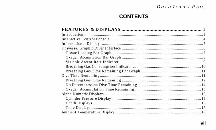
CONTENTS
FEATURES & DISPLAYS............................................................ 1Introduction .................................................................................................................. 2Interactive Control Console ......................................................................................... 4Informational Displays ................................................................................................. 5Universal Graphic Diver Interface .............................................................................. 6 Tissue Loading Bar Graph ....................................................................................... 7 Oxygen Accumlation Bar Graph .............................................................................. 8 Variable Ascent Rate Indicator ................................................................................9 Breathing Gas Consumption Indicator ................................................................. 10 Breathing Gas Time Remaining Bar Graph ......................................................... 11Dive Time Remaining ................................................................................................. 11 Breathing Gas Time Remaining ............................................................................ 12 No Decompression Dive Time Remaining ............................................................ 14 Oxygen Accumulation Time Remaining ............................................................... 15Alpha Numeric Displays ............................................................................................. 15 Cylinder Pressure Display...................................................................................... 15 Depth Displays ........................................................................................................ 16 Time Displays ......................................................................................................... 17Ambient Temperature Display .................................................................................. 18

®
viii
Audible Alarm ............................................................................................................. 19Message Box ................................................................................................................ 21Backlight Feature ....................................................................................................... 21Operating Temperature ............................................................................................. 22Sharing the DataTrans Plus ...................................................................................... 23Graphic Interface Legend .......................................................................................... 24
ACTIVATION & SETUP............................................................. 25Making the DataTrans Plus Personal ....................................................................... 26Activating the Display ................................................................................................ 27Surface Mode .............................................................................................................. 31Mode Menu System .................................................................................................... 31Entering Settings ....................................................................................................... 33 Set Time .................................................................................................................. 33 Set Date ................................................................................................................... 34 Set Alternate Display ............................................................................................. 35 Set Units of Measure .............................................................................................. 36 Breathing Gas & Depth Alarm Set Points ............................................................ 37 Depth Alarm Set Point ....................................................................................... 37
CONTENTS (continued )

DataTrans Plus
ix
Breathing Gas Alarm Set Point ......................................................................... 38 Set Depth & Breathing Gas Alarms .................................................................. 39 Turning Off the Audible Alarm ......................................................................... 40 Linking Procedure .................................................................................................. 41 Set Language .......................................................................................................... 43 Language Correction Procedure ........................................................................44
PREDIVE & DIVE MODES ....................................................... 45Positioning of the Display Module ............................................................................. 47Link Interruption Underwater .................................................................................. 47Operational Modes...................................................................................................... 48FO2 Mode ....................................................................................................................49 FO2 Set for Air ....................................................................................................... 49 Settings FO2 for Nitrox ......................................................................................... 50Plan Mode ................................................................................................................... 52No Decompression Dive Mode ................................................................................... 55Decompression Dive Mode ......................................................................................... 56Violation Modes .......................................................................................................... 57Gauge Mode ................................................................................................................57
CONTENTS (continued )
®
x
Ascending to the Surface ............................................................................................ 57Altitude Diving ........................................................................................................... 59
POST DIVE MODES .................................................................. 61Post Dive Surface Mode.............................................................................................. 62 Transition Period .................................................................................................... 62FO2 Mode ....................................................................................................................63Plan Mode ................................................................................................................... 63Time to Fly .................................................................................................................. 64Dive Log Mode ............................................................................................................ 65History Mode .............................................................................................................. 68External Access Mode................................................................................................. 69
HANDLING THE EXTREMES .................................................. 71Emergency Decompression ........................................................................................ 72 Gas Time Remaining During Decompression ....................................................... 75 Caution Zone (C.Z.) ................................................................................................. 76 Decompression Dive Mode ..................................................................................... 77
CONTENTS (continued )

DataTrans Plus
xi
Violation Modes .......................................................................................................... 79 Conditional Violation Mode ................................................................................... 79 Delayed Violation Mode.......................................................................................... 80 Immediate Violation Mode ..................................................................................... 83 Gauge Mode ............................................................................................................84 Permanent Violation .............................................................................................. 84Exceeding Maximum Operating Depth ..................................................................... 85Oxygen Exposure ........................................................................................................86 Partial Pressure of Oxygen .................................................................................... 87 High PO2 Dive Mode .............................................................................................. 87 Oxygen Accumulation ............................................................................................88 High Oxygen Accumulation ................................................................................... 89Message Box Warnings ............................................................................................... 90Unexpected Loss of Displayed Information .............................................................. 90
CARE & MAINTENANCE.......................................................... 93Care and Cleaning ...................................................................................................... 94Annual Inspections & Service .................................................................................... 95 How to Obtain Service ........................................................................................... 96
CONTENTS (continued )
®
xii
Battery Life ................................................................................................................. 97Low Battery Condition ............................................................................................... 99 Battery Replacement .............................................................................................. 99 Flooded Battery Compartment ............................................................................101Transmitter Installation Instructions ..................................................................... 102Transmitter Compatibilty with Nitrox ................................................................... 103
REFERENCE ............................................................................ 105More About Flying After Diving .............................................................................. 106More About Altitude Diving..................................................................................... 107More About Nitrox Diving .......................................................................................109Multiple Tissue Tracking ......................................................................................... 110No Decompression Limits ........................................................................................112Repetitive Decompression Diving ............................................................................112Specifications ............................................................................................................114Responsible Computer Diving ................................................................................. 117Language Cross Reference .......................................................................................118Glossary ..................................................................................................................... 121Accessories ................................................................................................................125DataTrans Plus Service Record ............................................................................... 126
CONTENTS (continued )

1
DataTrans Plus
FEATURESand
DISPLAYS
2
®
INTRODUCTION
Welcome to Oceanic and thank you for choosing DataTrans Plus!
Your new DataTrans Plus is a two component, hoseless, integrated system that consists of a computer DisplayModule and a radio frequency Transmitter that will be installed into a high pressure port of your regulatorfirst stage, or is built into an Oceanic DX3™ Integrated first stage regulator. The transmitter sends tank pres-sure data to the display module via a low frequency signal. In addition to nitrogen and oxygen loading data,breathing gas consumption is calculated and displayed in graphic and alpha/numerical formats on thecomputer’s screen. The Display Module can also be used without the transmitter as a stand alone, non-inte-grated computer, and will retain full use of all functions except those that related to tank pressure.
Your DataTrans Plus presents the information that you need before, during, and after your air (or nitrox)dives using Oceanic's intuitive combination of easy to read displays and unique identification icons. Tissueloading of nitrogen, accumulation of oxygen, ascent rate, breathing gas consumption rate, and breathing gastime remaining are presented as segmented bar graphs alongside color coded reference indicators that bringquick focus to these important status displays.
As you progress through this instructional guide, you will become familiar with all of the unique functions andfeatures available and see examples of the displays that you could expect to see in the various operationalmodes. Refer to the Glossary of terms on page 121, and keep the waterproof Review Card handy during yourdive trips. Although it will require an initial investment of time to become acquainted with the various icons
3
DataTrans Plus
and bar graphs of the Graphic Diver Interface, you’ll soon agree that the DataTrans Plus is easy to under-stand and use.
The DataTrans Plus has a wide array of features described in detail throughout the pages that follow. Due tothe importance that they be understood thoroughly prior to using the DataTrans Plus, information will be ex-panded upon and some refreshed as you proceed. Relax and read through the complete guide.
It is extremely important that you:• Read this owner's guide in sequence and understand it completely before attempting to use
the DataTrans Plus.• Check the DataTrans Plus frequently during your dive.• You must also be a trained diver, certified by a recognized training agency in Scuba diving.• Prior to using the oxygen related features of the DataTrans Plus, you must also be trained
and certified for diving with enriched nitrogen-oxygen (nitrox) mixtures by a recognizedtraining agency.
Remember that the rules you learned in your basic scuba certification course still apply to the diving you willdo while using a dive computer - some will become even more important. Technology is no substitute for com-mon sense, and a dive computer only provides the person using it with data, not the knowledge to use it.
Be a RESPONSIBLE DIVER at all times.
4
®
INTERACTIVE CONTROL CONSOLE
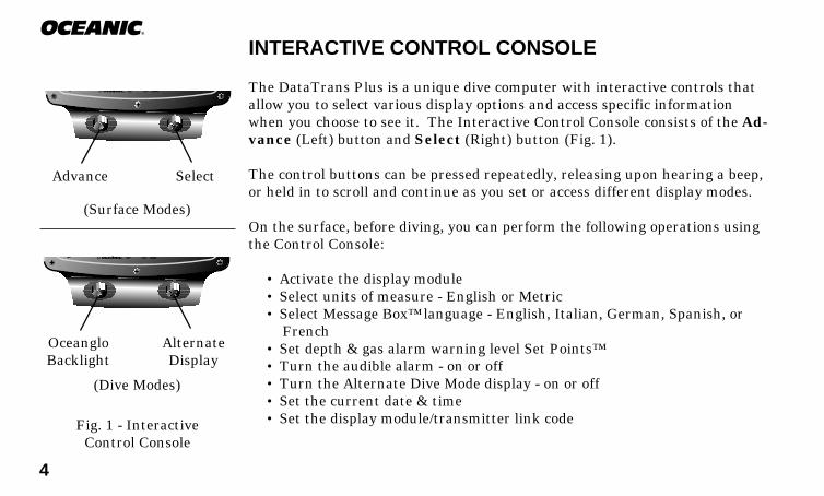
The DataTrans Plus is a unique dive computer with interactive controls thatallow you to select various display options and access specific informationwhen you choose to see it. The Interactive Control Console consists of the Ad-vance (Left) button and Select (Right) button (Fig. 1).
The control buttons can be pressed repeatedly, releasing upon hearing a beep,or held in to scroll and continue as you set or access different display modes.
On the surface, before diving, you can perform the following operations usingthe Control Console:
• Activate the display module• Select units of measure - English or Metric• Select Message Box™ language - English, Italian, German, Spanish, or
French• Set depth & gas alarm warning level Set Points™• Turn the audible alarm - on or off• Turn the Alternate Dive Mode display - on or off• Set the current date & time• Set the display module/transmitter link code
(Surface Modes)
®
SelectAdvance
®
AlternateDisplay
OceangloBacklight
(Dive Modes)
Fig. 1 - InteractiveControl Console

5
DataTrans PlusAlso while on the surface, you can access the following modes with the ControlConsole:
• FO2 mode - to program the percentage of oxygen in the nitrox mix.• Plan mode - to view no decompression limits and plan your next dive.• Log mode - to view data from your 12 most recent dives.• History mode - to view the total number of dives, maximum depth, etc.• Set mode - to establish prefered selections.• External Access mode - to download (copy) dive data from the
DataTrans Plus to a unique PC log/profile program.
During the Dive mode, the Advance (Left) button can be used to activate thedisplay's Oceanglo™ backlight, and the Select (Right) button can be used to ac-cess an Alternate Dive mode, that displays additional information includingmaximum depth, bottom time and temperature.
INFORMATIONAL DISPLAYS
Operational modes and status information is visually represented numericallyand/or graphically and can be understood at a glance with the aide of universalicons (Fig. 2) that identify and bring quick focus to the displays. Also, segmentedbar graphs will show how close you are to critical limits.
In critical situations, a Message Box™ flashes urgent messages, while an au-
Fig. 2 - Universal Icons
®
DECOC.Z. C.Z. O2NO DECO
0 5 10 20 30 40 50 60

6
®
dible alarm sounds to alert you to check this information. These concise,simple messages (Fig. 3), such as “TOO FAST” or “TOO DEEP" are displayedin the language that you choose during setup.
Each DataTrans Plus numeric and graphic display represents aunique piece of information. It is imperative that you understandthe formats, ranges, and values of the information represented toavoid any possible misunderstanding that could result in error.
NOTE: Throughout this owner's guide reference is made to theterm 'breathing gas'. The rational being that the DataTransPlus can be used for 'air' dives or 'nitrox' dives. For claritythese terms are defined as -
Breathing Gas - the gaseous mixture breathed during a dive.Air - a breathing gas that contains approximately 21% oxygenand 79% nitrogen (nature's common nitrogen-oxygen mixture).Nitrox - a nitrogen-oxygen breathing gas that contains a higherfraction of oxygen (22 to 50%) than air.
UNIVERSAL GRAPHIC DIVER INTERFACE ™
Five bar graphs referred to as the Universal Graphic Diver Interface™ appeararound the perimeter of the DataTrans Plus screen (Fig. 4). These segmented
Fig. 4 - Bar Graph Displays
®
DECOC.Z. C.Z. O2NO DECO
0 5 10 20 30 40 50 60
®
DECOC.Z. C.Z.
PSIBAR M
FT
O2NO DECO
0 5 10 20 30 40 50 60
MAX
Fig. 3 - Message Box
R2

7
DataTrans Plus
Fig. 5 - Tissue LoadingBar Graph
bar graphs are located next to green, yellow, and red color coded portions of theperipheral decal that denote normal, caution, and danger zones, respectively.When underwater, you can quickly focus on the bar graphs to make sure thatthey are in the green. You can quickly verify that you're not getting too closeto the no decompression limit or the oxygen tolerance limit, or ascending toofast, or consuming breathing gas too fast, or running low on breathing gas.
Tissue Loading Bar Graph™
The Tissue Loading Bar Graph™ represents nitrogen loading (Fig. 5), showingyour relative no decompression or decompression status. As your depth andelapsed dive time increase, segments will add to the graph beginning in thelower left portion of the screen. As you ascend to shallower depths, this bargraph will begin to recede, indicating that additional no decompression time isallowed for multilevel diving.
The Tissue Loading Bar Graph monitors 12 different nitrogen compartmentssimultaneously and displays the one that is in control of your dive. It is dividedinto a green No Decompression zone (NO DECO), a yellow Caution zone (C.Z.),and a red Decompression zone (DECO). The bar graph gives a visual represen-tation of just how close you are to the no decompression limit with a yellowCaution (C.Z.) Zone.
This Caution Zone portion of the bar graph (Fig. 5a) allows you to make a deci-sion regarding safety stop duration or necessity. While you cannot provide a
®
DECOC.Z. C.Z. O2NO DECO
0 5 10 20 30 40 50 60
a
b
8
®
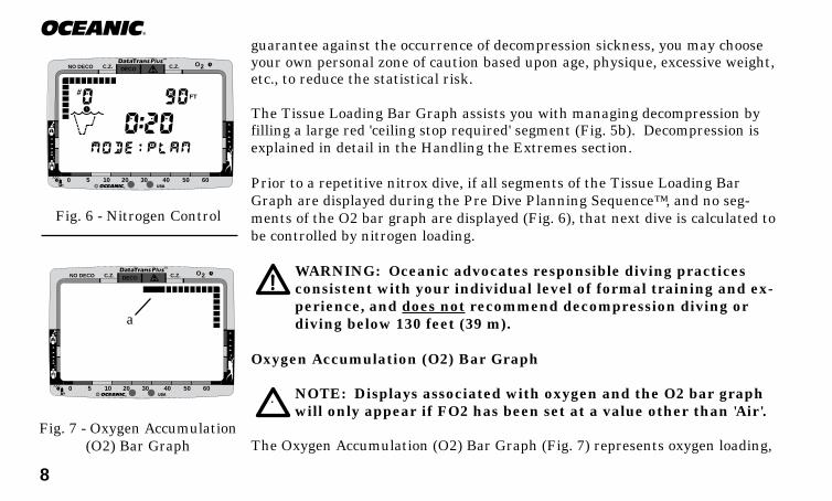
guarantee against the occurrence of decompression sickness, you may chooseyour own personal zone of caution based upon age, physique, excessive weight,etc., to reduce the statistical risk.
The Tissue Loading Bar Graph assists you with managing decompression byfilling a large red 'ceiling stop required' segment (Fig. 5b). Decompression isexplained in detail in the Handling the Extremes section.
Prior to a repetitive nitrox dive, if all segments of the Tissue Loading BarGraph are displayed during the Pre Dive Planning Sequence™, and no seg-ments of the O2 bar graph are displayed (Fig. 6), that next dive is calculated tobe controlled by nitrogen loading.
WARNING: Oceanic advocates responsible diving practicesconsistent with your individual level of formal training and ex-perience, and does not recommend decompression diving ordiving below 130 feet (39 m).
Oxygen Accumulation (O2) Bar Graph
NOTE: Displays associated with oxygen and the O2 bar graphwill only appear if FO2 has been set at a value other than 'Air'.
The Oxygen Accumulation (O2) Bar Graph (Fig. 7) represents oxygen loading,
Fig. 6 - Nitrogen Control
Fig. 7 - Oxygen Accumulation(O2) Bar Graph
®
DECOC.Z. C.Z.
FT
O2NO DECO
0 5 10 20 30 40 50 60
®
DECOC.Z. C.Z. O2NO DECO
0 5 10 20 30 40 50 60
a
9
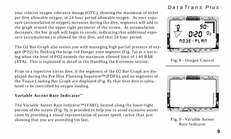
DataTrans Plusyour relative oxygen tolerance dosage (OTU), showing the maximum of eitherper dive allowable oxygen, or 24 hour period allowable oxygen. As your expo-sure (accumulation of oxygen) increases during the dive, segments will add tothe graph around the upper right perimeter of the screen. As accumulationdecreases, the bar graph will begin to recede, indicating that additional expo-sure (accumulation) is allowed for that dive, and that 24 hour period.
The O2 Bar Graph also assists you with managing high partial pressure of oxy-gen (PO2) by flashing the large red Danger zone segment (Fig. 7a) as a warn-ing when the level of PO2 exceeds the maximum allowed limit of 1.60 BAR(ATA). This is explained in detail in the Handling the Extremes section.
Prior to a repetitive nitrox dive, if the segments of the O2 Bar Graph are dis-played during the Pre Dive Planning Sequence™ (PDPS), and no segments ofthe Tissue Loading Bar Graph are displayed (Fig. 8), that next dive is calcu-lated to be controlled by oxygen loading.
Variable Ascent Rate Indicator™
The Variable Ascent Rate Indicator™ (VARI), located along the lower/rightportion of the screen (Fig. 9), is provided to help you to avoid excessive ascentrates by providing a visual representation of ascent speed, rather than justshowing that you are ascending too fast.
Fig. 8 - Oxygen Control
Fig. 9 - Variable AscentRate Indicator
®
DECOC.Z. C.Z.
FT
O2NO DECO
0 5 10 20 30 40 50 60
®
DECOC.Z. C.Z. O2NO DECO
0 5 10 20 30 40 50 60

10
®
The 8 triangular segments of the bar graph, located beside green, yellow, andred reference zones, appear beginning from the bottom and may be consideredan ascent rate speedometer. Green is a 'normal' rate, yellow is a 'caution' rate,and red is 'Too Fast'. The actual speeds that the VARI segments represent areshown at the left.
When your ascent rate exceeds the maximum recommended rate of 60 feet (18meters) per minute, the bar graph segments will enter the red zone and all dis-played segments will flash once per second until your ascent speed is slowed.When this occurs, you should immediately slow your ascent.
The Variable Ascent Rate Indicator is a unique feature of Oceanic dive com-puters that has been granted U.S. Patent No. 5,156,055.
Breathing Gas Consumption Indicator
The Breathing Gas Consumption Indicator bar graph located at the lower/leftportion of the display (Fig. 10) is a true biofeedback monitor that indicatesyour current breathing rate as compared to your personally establishedbreathing parameters. The comparison is based upon an average rate estab-lished during the first 70 seconds of breathing that is sensed.
After the comparison, the bar graph will provide you with continuous visualindication of your breathing rate as it slows or increases. Use of Oceanic's pat-
Fig. 10 - Breathing GasConsumption Indicator
®
DECOC.Z. C.Z. O2NO DECO
0 5 10 20 30 40 50 60
VARI Segments = Speed (rate)0 = 0 - 10 fpm (0 - 3 mpm)1 = 11 - 20 fpm (3 - 6 mpm)2 = 21 - 30 fpm (6 - 9 mpm)3 = 31 - 40 fpm (9 - 12 mpm)4 = 41 - 50 fpm (12 - 15 mpm)5 = 51 - 60 fpm (15 - 18 mpm)6 = 61 - 90 fpm (18 - 27 mpm)7 = 91 - 120 fpm (27 - 36 mpm)8 = >120 fpm (>36 mpm)(when > 5, the segments flash)
11
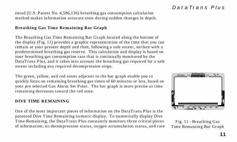
DataTrans Plusented (U.S. Patent No. 4,586,136) breathing gas consumption calculationmethod makes information accurate even during sudden changes in depth.
Breathing Gas Time Remaining Bar Graph
The Breathing Gas Time Remaining Bar Graph located along the bottom ofthe display (Fig. 11) provides a graphic representation of the time that you canremain at your present depth and then, following a safe ascent, surface with apredetermined breathing gas reserve. This calculation and display is based onyour breathing gas consumption rate that is continually monitored by theDataTrans Plus, and it takes into account the breathing gas required for a safeascent including any required decompression stops.
The green, yellow, and red zones adjacent to the bar graph enable you toquickly focus on remaining breathing gas times of 60 minutes or less, based onyour pre selected Gas Alarm Set Point. The bar graph is more precise as timeremaining decreases toward the red zone.
DIVE TIME REMAINING
One of the most important pieces of information on the DataTrans Plus is thepatented Dive Time Remaining numeric display. To numerically display DiveTime Remaining, the DataTrans Plus constantly monitors three critical piecesof information; no decompression status, oxygen accumulation status, and rate
Fig. 11 - Breathing GasTime Remaining Bar Graph
®
DECOC.Z. C.Z. O2NO DECO
0 5 10 20 30 40 50 60

12
®
of breathing gas consumption. The Dive Time Remaining display will indicatethe time that is more critical for you at that particular moment (i.e.; whichevertime is the least amount available of the three). The time being displayed isidentified by the No Decompression Dive Time icon, or Gas Time Remainingicon displayed to the left of the numeric display, or the O2 symbol displayed tothe right of the numeric display (Fig. 12).
Knowing that you have 45 minutes of no decompression time remaining is notas critical as knowing that you only have 40 minutes of breathing gas time re-maining. Or, knowing that you have 40 minutes of breathing gas time remain-ing is not as critical as knowing that you only have 35 minutes of oxygen accu-mulation time remaining. The DataTrans Plus presents the dive time remain-ing that is considered to be of primary importance. This unique feature of se-lect Oceanic dive computers has been granted U.S. Patent No. 4,586,136.
Breathing Gas Time Remaining
Breathing Gas Time Remaining will appear as the numeric Dive Time Remain-ing display (Fig. 13) only when it is less than No Decompression Time Remain-ing and Oxygen Accumulation Time Remaining. Breathing Gas Time Remain-ing of 60 minutes, or less, will be displayed continuously as the Gas Time Re-maining Bar Graph (Fig. 13a) regardless of which time is being displayed asthe numeric Dive Time Remaining. The bar graph represents only BreathingGas Time information and it will be the only indication of breathing gas time
Fig. 13 - Breathing GasTime Remaining
®
DECOC.Z. C.Z.
PSI FT
O2NO DECO
0 5 10 20 30 40 50 60
a
(No Decompression Time)
Fig. 12 - Dive TimeRemaining Identification
(Oxygen Accumulation Time)
(Breathing Gas Time)

13
DataTrans Plusremaining if you are in a decompression or violation mode.
The DataTrans Plus calculates Breathing Gas Time Remaining using a pat-ented algorithm that is based on a diver's individual breathing gas consump-tion rate and depth. Tank pressure is measured once each second, and an av-erage rate of consumption is calculated over a 90 second period. This rate ofconsumption is then used in conjunction with a knowledge of the depth depen-dence to predict the breathing gas required for a safe ascent including any re-quired decompression stops.
Breathing gas consumption and depth are continuously monitored, andBreathing Gas Time Remaining reflects any change in your circumstances.For example, when a buddy starts breathing from your octopus or you sud-denly find yourself swimming against a strong current and begin breathingmore rapidly, the DataTrans Plus will recognize this change and adjust yourBreathing Gas Time Remaining accordingly.
Remember, the Breathing Gas Time Remaining is the time you can remain atthe present depth and still surface with the tank pressure reserve (Gas AlarmSet Point) that you set during setup. When Gas Time Remaining indicateszero, you should immediately initiate a controlled ascent. However, there is noreason to panic, the DataTrans Plus has allowed for the breathing gas neces-sary for a safe ascent including any emergency decompression stops.
RE
SP
ONSIBLE
DIV
ER
14
®
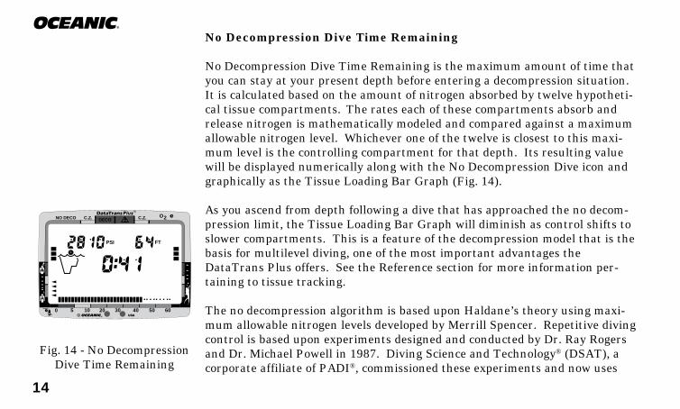
No Decompression Dive Time Remaining
No Decompression Dive Time Remaining is the maximum amount of time thatyou can stay at your present depth before entering a decompression situation.It is calculated based on the amount of nitrogen absorbed by twelve hypotheti-cal tissue compartments. The rates each of these compartments absorb andrelease nitrogen is mathematically modeled and compared against a maximumallowable nitrogen level. Whichever one of the twelve is closest to this maxi-mum level is the controlling compartment for that depth. Its resulting valuewill be displayed numerically along with the No Decompression Dive icon andgraphically as the Tissue Loading Bar Graph (Fig. 14).
As you ascend from depth following a dive that has approached the no decom-pression limit, the Tissue Loading Bar Graph will diminish as control shifts toslower compartments. This is a feature of the decompression model that is thebasis for multilevel diving, one of the most important advantages theDataTrans Plus offers. See the Reference section for more information per-taining to tissue tracking.
The no decompression algorithm is based upon Haldane’s theory using maxi-mum allowable nitrogen levels developed by Merrill Spencer. Repetitive divingcontrol is based upon experiments designed and conducted by Dr. Ray Rogersand Dr. Michael Powell in 1987. Diving Science and Technology® (DSAT), acorporate affiliate of PADI®, commissioned these experiments and now uses
Fig. 14 - No DecompressionDive Time Remaining
®
DECOC.Z. C.Z.
PSI FT
O2NO DECO
0 5 10 20 30 40 50 60
15
DataTrans Plusthe findings in the Recreational Dive Planner™ distributed by PADI.
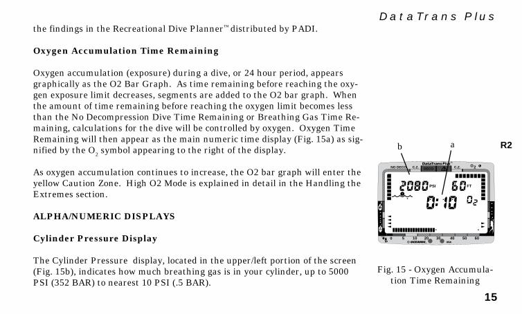
Oxygen Accumulation Time Remaining
Oxygen accumulation (exposure) during a dive, or 24 hour period, appearsgraphically as the O2 Bar Graph. As time remaining before reaching the oxy-gen exposure limit decreases, segments are added to the O2 bar graph. Whenthe amount of time remaining before reaching the oxygen limit becomes lessthan the No Decompression Dive Time Remaining or Breathing Gas Time Re-maining, calculations for the dive will be controlled by oxygen. Oxygen TimeRemaining will then appear as the main numeric time display (Fig. 15a) as sig-nified by the O2 symbol appearing to the right of the display.
As oxygen accumulation continues to increase, the O2 bar graph will enter theyellow Caution Zone. High O2 Mode is explained in detail in the Handling theExtremes section.
ALPHA/NUMERIC DISPLAYS
Cylinder Pressure Display
The Cylinder Pressure display, located in the upper/left portion of the screen(Fig. 15b), indicates how much breathing gas is in your cylinder, up to 5000PSI (352 BAR) to nearest 10 PSI (.5 BAR).
Fig. 15 - Oxygen Accumula-tion Time Remaining
®
DECOC.Z. C.Z.
PSI FT
O2NO DECO
0 5 10 20 30 40 50 60
b a R2
16
®
The value of pressure will be displayed during all dive modes when the DisplayModule is linked to the Transmitter and within the operating range. Linkingis explained in more detail in the Pre Dive and Dive Mode section.
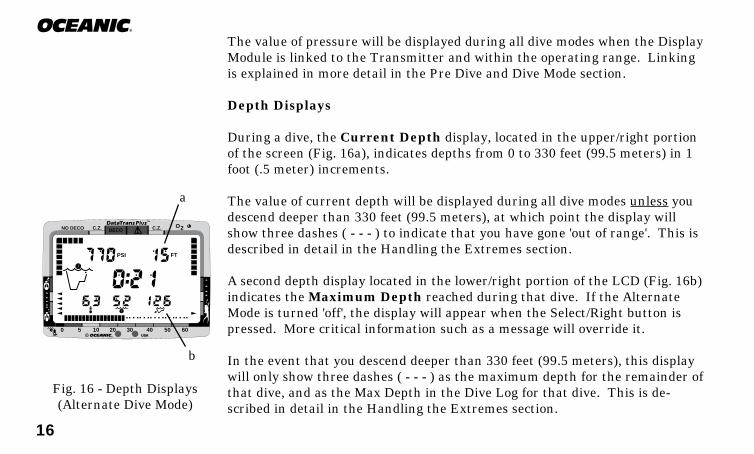
Depth Displays
During a dive, the Current Depth display, located in the upper/right portionof the screen (Fig. 16a), indicates depths from 0 to 330 feet (99.5 meters) in 1foot (.5 meter) increments.
The value of current depth will be displayed during all dive modes unless youdescend deeper than 330 feet (99.5 meters), at which point the display willshow three dashes ( - - - ) to indicate that you have gone 'out of range'. This isdescribed in detail in the Handling the Extremes section.
A second depth display located in the lower/right portion of the LCD (Fig. 16b)indicates the Maximum Depth reached during that dive. If the AlternateMode is turned 'off', the display will appear when the Select/Right button ispressed. More critical information such as a message will override it.
In the event that you descend deeper than 330 feet (99.5 meters), this displaywill only show three dashes ( - - - ) as the maximum depth for the remainder ofthat dive, and as the Max Depth in the Dive Log for that dive. This is de-scribed in detail in the Handling the Extremes section.
Fig. 16 - Depth Displays(Alternate Dive Mode)
®
DECOC.Z. C.Z.
PSI FT
O2NO DECO
0 5 10 20 30 40 50 60
a
b

17
DataTrans Plus
®
DECOC.Z. C.Z.
PSI FT
O2NO DECO
0 5 10 20 30 40 50 60
®
DECOC.Z. C.Z.
PSI FT
O2NO DECO
0 5 10 20 30 40 50 60
During a Decompression Dive the required Ceiling Stop Depth appears inthe lower/left portion of the screen (Fig. 17a). The display toggles with themessage CEILING once every 15 seconds while in the Decompression Mode.This is described in detail in the Handling the Extremes section.
Time Displays
The Main Time display, located in the center of the screen (Fig. 18a), haslarger digits than the other numerial displays. Depending on the operatingmode that the DataTrans Plus is in at the time, the display indicates elapsedSurface Time, theoretical Dive Time Available, Dive Time Remaining, or TotalAscent Time required.
A second Time display appears in the lower portion of the screen. Dependingon the operating mode that the DataTrans Plus is in at the time, the displayindicates Elapsed Dive Time (Fig. 18b), Decompression Stop Time required,Time of Day, or Time to Fly.
Each display is described in detail in subsequent sections of this owner's guide.
Most of the time displays are shown in hour:minute format (i.e. 1:02 repre-sents one hour and two minutes, not 102 minutes!). The colon that separateshours and minutes blinks once per second when the display is indicating realtime such as elapsed Surface Time. Dive Time Available, No Decompression
Fig. 17 - Depth Displays(Decompression Dive Mode)
Fig. 18 - Time Displays(Alternate Dive Mode)
b
b
a
R2

18
®
Dive Time Remaining, Total Ascent Time required, or Time to Fly are calcu-lated projections of time and use a solid (non-blinking) colon to indicate thatthey are counting down, rather than counting up.
Elapsed Dive Time, that appears in the lower/center portion of the display(Fig. 19a) when the Alternate Mode is turned 'on', is in minute format with amaximum display value of 99 minutes. If the Alternate Mode has been turned'off', Elapsed Dive Time can be displayed by depressing the Select/Right but-ton.
Ambient Temperature Display
When the Alternate Mode is turned 'on', ambient Temperature will appear inthe lower/left portion of the display(Fig. 19b). If the Alternate Mode has beenturned 'off', Temperature can be displayed by depressing the Select/Right but-ton.
NOTE: More critical information such as Ceiling Stop Depthrequired or a message will override the lower displays.
Fig. 19 - Alternate Dive Mode
®
DECOC.Z. C.Z.
PSI FT
O2NO DECO
0 5 10 20 30 40 50 60
abResponsible

19
DataTrans PlusAUDIBLE ALARM
When you are approaching dangerous situations, the DataTrans Plus alertsyou to check the Message Box, Graphic Diver Interface, and numeric displays.There are four Audible Alarms.
Potential Danger – One Double Beep
During situations that may pose potential danger, one Double Beep is emittedfrom the DataTrans Plus. These situations are as follows:
• Entry into decompression.• Decreasing to 5 minutes of Breathing Gas Dive Time Remaining.• Partial pressure of oxygen equal to or greater than 1.40 ATA.
Immediate Danger – continuous One Beep per Second
When the DataTrans Plus senses immediate danger to you, it emits One Beepper Second until one of the following situations is corrected:
• Descent deeper than the Depth Alarm Set Point.• Continuous interruption of signal link of more than 60 seconds.• Ascent to a depth shallower than a required stop depth.
(Immediate Danger)
BEEP!
BEEP!
BEEP...
BEEP...
BEEP...
(Potential Danger)
20
®
• Ascent rate that exceeds 60 ft./min (18 m/min).• Gas Time Remaining equals required Decompression time.• Gas Time Remaining equals zero (0:00).• Partial pressure of oxygen equal to or greater than 1.60 ATA.• Oxygen accumulation greater than the allowed per dive or 24 hour limit.
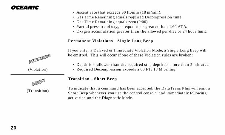
Permanent Violations – Single Long Beep
If you enter a Delayed or Immediate Violation Mode, a Single Long Beep willbe emitted. This will occur if one of these Violation rules are broken:
• Depth is shallower than the required stop depth for more than 5 minutes.• Required Decompression exceeds a 60 FT/ 18 M ceiling.
Transition – Short Beep
To indicate that a command has been accepted, the DataTrans Plus will emit aShort Beep whenever you use the control console, and immediately followingactivation and the Diagnostic Mode.
(Transition)
BEEP!
(Violation)
BEEEEEEP!
21
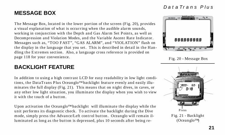
DataTrans PlusMESSAGE BOX
The Message Box, located in the lower portion of the screen (Fig. 20), providesa visual explanation of what is occurring when the audible alarm sounds,working in conjunction with the Depth and Gas Alarm Set Points, as well asDecompression and Violation Modes, and the Variable Ascent Rate Indicator.Messages such as, “TOO FAST”, “GAS ALARM”, and “VIOLATION” flash onthe display in the language that you set. This is described in detail in the Han-dling the Extremes section. Also, a language cross reference is provided onpage 118 for your convenience.
BACKLIGHT FEATURE
In addition to using a high contrast LCD for easy readability in low light condi-tions, the DataTrans Plus Oceanglo™ backlight feature evenly and easily illu-minates the full display (Fig. 21). This means that on night dives, in caves, orany other low light situation, you illuminate the display when you wish to viewit with the touch of a button.
Upon activation the Oceanglo™ backlight will illuminate the display while theunit performs its diagnostic check. To activate the backlight during the Divemode, simply press the Advance/Left control button. Oceanglo will remain il-luminated as long as the button is depressed, plus 10 seconds after being re-
Fig. 20 - Message Box
Fig. 21 - Backlight(Oceanglo™)
®
DECOC.Z. C.Z. O2NO DECO
0 5 10 20 30 40 50 60
®
DECOC.Z. C.Z.
PSI FT
O2NO DECO
0 5 10 20 30 40 50 60
Press

22
®
leased (for a maximum of 15 seconds).
Oceanic recommends that you always carry primary and backup divelights when conducting dives that could include low light situations.
OPERATING TEMPERATURE
The DataTrans Plus will operate in almost any temperature diving environ-ment in the world (Fig. 22) between 32 and 140°F (0 and 60°C). At extremelylow temperatures, the LCD may become sluggish, but this will not affect it'saccuracy. If stored or transported in extremely low temperature areas (belowfreezing), you should warm the module and its batteries with body heat beforediving.
Even though the DataTrans Plus will operate in this wide range of tempera-tures, it is possible to damage the electronics if left exposed to directsunlight, or in a hot confined space (like a car trunk). After the dive,cover the Display Module and keep it out of the sun. If inadvertently left inthe direct sunlight for a long period, the LCD display may become totallyblack. If this occurs, immediately immerse the Display Module in water. Thedisplay should recover its normal appearance after a few minutes. Damagefrom excess heat, or cold, is not covered by the DataTrans Plus twoyear limited warranty.
Fig. 22 - OperatingTemperature Range
140°F (60°C)
32°F (0°C)
®
DECOC.Z. C.Z.
PSI FT
O2NO DECO
0 5 10 20 30 40 50 60
23
DataTrans PlusSHARING THE DATATRANS PLUS
WARNING: Never participate in sharing or swapping of a divecomputer. Doing so may result in injury or death.
The DataTrans Plus provides information based upon a diver’s personal diveprofile, and therefore must not be “shared” between divers. You shouldnever, under any circumstances, swap your computer with another unit be-tween dives, or share your computer with another diver underwater. It is im-possible for two divers to stay precisely together underwater, and yourcomputer's dive profile tracking of previous dives will be pertinent toyou only. Nitrogen and oxygen loading of a second user may be significantlydifferent and thus swapping dive computers could lead to inaccurate and po-tentially dangerous predictions of decompression and oxygen accumulationstatus. This rule applies to the use of all dive computers, but is especially im-portant when using the DataTrans Plus, due to the personal information itprovides.
RE
SP
ONSIBLE
DIV
ER

24
®
Fig. 23 - Graphic InterfaceLegend
Key:a - Gas Consumption Indicatorb - Tissue Loading Bar Graphc - O2 Accumulation Bar Graphd - Variable Ascent Rate Indicatore - Gas Time Remaining Bar Graphf - Transmitter Link icong - Operating mode icon (detail A)h - Oxygen mode symboli - Low Battery icon (detail B)j - Maximum Depth iconk - Elapsed Dive Time iconl - Temperature iconm - PC Interface sensors
®
DECOC.Z. C.Z.
PSIBAR M
FT
O2NO DECO
0 5 10 20 30 40 50 60
MAX
a
m je
kl
di
h
cb
g
f

25
DataTrans Plus
ACTIVATIONand
SETUP

26
®
MAKING THE DATATRANS PLUS PERSONAL
Before you dive with the DataTrans Plus for the first time, you will need to be-come acquainted with its interactive features, and select your personal displaysettings using the Control Console and Mode Menu.
The transmitter must first be installed into a high pressure port of your regu-lator first stage, facing to one side (Fig. 24) - unless you purchased the DX3™
Integrated first stage in which the transmitter is a built-in component (Fig.25). Oceanic strongly recommends that installation be performed by an Au-thorized Oceanic Dealer at the time of purchase. If this is not possible, refer tothe instructions for this procedure on page 102.
NOTE: The DataTrans Plus transmitter is compatible with allOceanic first stages, but cannot be guaranteed to fit certainmodels produced by other manufacturers. Check with your Au-thorized Oceanic Dealer to verify compatibility with your regu-lator first stage.
For the Display Module to receive a tank pressure signal from the Transmit-ter, the two devices must first be 'Linked'. The code (serial number) of theTransmitter must be entered as the 'Link' code in the Display Module.Fig. 25 - DX3 Integrated
First Stage
Fig. 24 - StandardFirst Stage

27
DataTrans PlusIf your Display Module and Transmitter were packaged and shipped from thefactory as a complete system, the code of your Transmitter has already beenentered as the 'Link' code in your Display Module. If the two units have beenpurchased separately by you or your Authorized Oceanic Dealer, it will be nec-essary to set the Link code in the Display Module so that a tank pressure sig-nal can be received. If the Display Module has been purchased as a standalone computer without the Transmitter, it has been preset at the factory as anon-linked unit, but can easily be reset at any time to 'Link' with a Transmit-ter code (serial number) using the Control Console.
ACTIVATING THE DISPLAY
Before activating the Display Module, the regulator containing the transmittermust be connected to a full tank and pressurized by slowly opening the tankvalve. Tank pressure of 50 psi (3.5 BAR ), or greater, is required for the trans-mitter to activate. Position the display module within 3 feet (1 m) of and par-allel to the transmitter (Fig. 26), and hold it in this location during activation.
WARNING: Never activate the DataTrans Plus underwater.This may result in inaccurate depth and no-decompression timedisplays. If activated deeper than 4 feet (1 meter) underwater amessage "TOO DEEP" will appear and the unit will shut off. Fig. 26 - Positioning
During Activation
®
DE
CO
C.Z
.
C.Z
.
PS
IB
AR
MFT
O2
NO
DE
CO
05
1020
3040
5060
MA
X
R2

28
®
To activate the Display Module, press the Select/Right button once and release.
The DataTrans Plus will immediately enter Diagnostic Mode, displaying all“8’s”, followed by “dashes”, and then a countdown from 9 to 0 (Fig. 27). TheMessage Box will read SELF - TEST and the Oceanglo backlight will illumi-nate the display throughout the diagnostic check. A single beep will be emit-ted to indicate successful completion of the operation.
While conducting diagnostics, the DataTrans Plus checks its display functions,coded frequency link to the transmitter, and battery voltage to ensure that ev-erything is working correctly.
If the Display Module is already set to the Transmitter's link code, the Linkicon will disappear from the screen and tank pressure will be displayed nu-merically (Fig. 28).
It will also check the ambient barometric pressure, and calibrate its presentdepth as zero. At elevations of 2,000 ft. (610 m) or higher, it will recalibrateitself to measure depth in feet of fresh water instead of feet of sea water.
Fig. 28 - DiagnosticsSuccessfull
®
DECOC.Z. C.Z.
PSI FT
O2NO DECO
0 5 10 20 30 40 50 60
Fig. 27 - Diagnosticsin Progress
®
DECOC.Z. C.Z.
PSIBAR M
FT
O2NO DECO
0 5 10 20 30 40 50 60
MAX
R2
R2
29
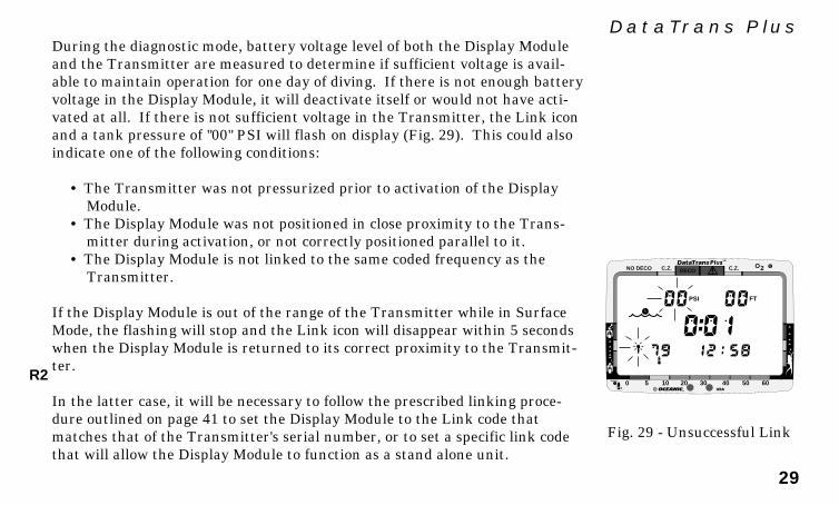
DataTrans PlusDuring the diagnostic mode, battery voltage level of both the Display Moduleand the Transmitter are measured to determine if sufficient voltage is avail-able to maintain operation for one day of diving. If there is not enough batteryvoltage in the Display Module, it will deactivate itself or would not have acti-vated at all. If there is not sufficient voltage in the Transmitter, the Link iconand a tank pressure of "00" PSI will flash on display (Fig. 29). This could alsoindicate one of the following conditions:
• The Transmitter was not pressurized prior to activation of the DisplayModule.
• The Display Module was not positioned in close proximity to the Trans-mitter during activation, or not correctly positioned parallel to it.
• The Display Module is not linked to the same coded frequency as theTransmitter.
If the Display Module is out of the range of the Transmitter while in SurfaceMode, the flashing will stop and the Link icon will disappear within 5 secondswhen the Display Module is returned to its correct proximity to the Transmit-ter.
In the latter case, it will be necessary to follow the prescribed linking proce-dure outlined on page 41 to set the Display Module to the Link code thatmatches that of the Transmitter's serial number, or to set a specific link codethat will allow the Display Module to function as a stand alone unit.
Fig. 29 - Unsuccessful Link
®
DECOC.Z. C.Z.
PSI FT
O2NO DECO
0 5 10 20 30 40 50 60R2
30
®
Low Battery conditions and battery power conservation are described in moredetail in the Care & Maintenance section.
WARNING: If either or both of the Low Battery icons remainon display following diagnostics, Oceanic strongly recommendsthat you DO NOT dive until the batteries are replaced. See thebattery replacement procedure on page 99.
If no dive is made within 2 hours after initial activation, the Display Modulewill automatically deactivate to conserve its battery power. Check your Dis-play Module before entering the water to verify that it is functioning anddoesn’t need reactivation.
To save its battery power while on the surface, the Display Module will stopsearching for a Transmitter signal after 10 minutes. The signal Link can berestored by depressing the Select/Right button on the Display Module. It willalso be restored automatically upon descent on a dive.
WARNING: During activation and diagnostics, if any display ormessage varies from the information presented here, return theDataTrans Plus to your Oceanic Dealer for inspection.
Be a -RESPONSIBLE DIVER
at all times.
RE
SP
ONSIBLE
DIV
ER
31
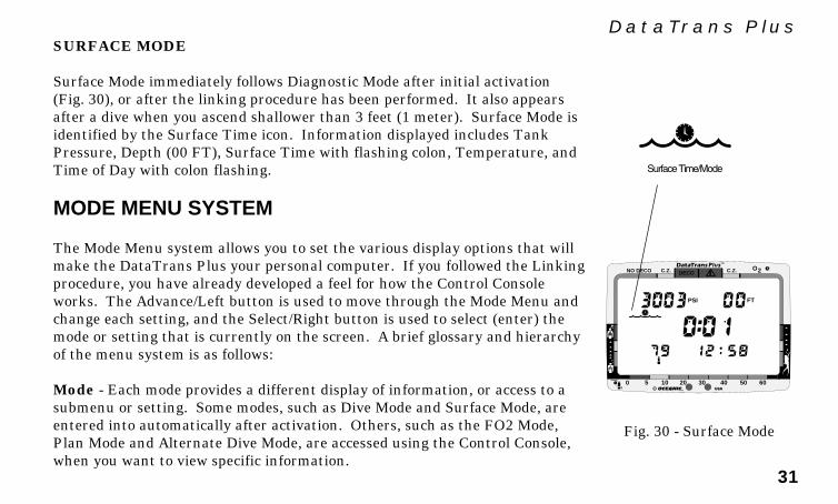
DataTrans PlusSURFACE MODE
Surface Mode immediately follows Diagnostic Mode after initial activation(Fig. 30), or after the linking procedure has been performed. It also appearsafter a dive when you ascend shallower than 3 feet (1 meter). Surface Mode isidentified by the Surface Time icon. Information displayed includes TankPressure, Depth (00 FT), Surface Time with flashing colon, Temperature, andTime of Day with colon flashing.
MODE MENU SYSTEM
The Mode Menu system allows you to set the various display options that willmake the DataTrans Plus your personal computer. If you followed the Linkingprocedure, you have already developed a feel for how the Control Consoleworks. The Advance/Left button is used to move through the Mode Menu andchange each setting, and the Select/Right button is used to select (enter) themode or setting that is currently on the screen. A brief glossary and hierarchyof the menu system is as follows:
Mode - Each mode provides a different display of information, or access to asubmenu or setting. Some modes, such as Dive Mode and Surface Mode, areentered into automatically after activation. Others, such as the FO2 Mode,Plan Mode and Alternate Dive Mode, are accessed using the Control Console,when you want to view specific information.
Fig. 30 - Surface Mode
®
DECOC.Z. C.Z.
PSI FT
O2NO DECO
0 5 10 20 30 40 50 60

32
®
Menu - The main menu allows interactive access from the Surface Mode tovarious other modes used while on the surface.
Settings - These are display options (settings) that are determined by you be-fore going diving. For example, with 'alarms' you can set the values at whichdepth and tank pressure will alert you when you are going too deep or runninglow on breathing gas.
NOTE: If the DataTrans Plus is left unattended for five min-utes while in the Mode Menu, it will automatically revert toSurface Mode.
Responsible
Mode Menu Sequence• Surface• FO2• Plan• Log• History• Set• External Access
Settings Sequence• Time• Date• Alternate• Unit• Alarms• Link• Language

33
DataTrans PlusENTERING SETTINGS
Before going diving, enter the general settings to be used for each of yourdives. These include - Time, Date, Alternate Display, Units of Measure, DepthAlarm, Gas (tank pressure) Alarm, Link code, and Language.
Note that FO2 is a 'pre dive' setting that must be entered prior to each nitroxdive. Setting the FO2 value for the nitrox mixture being used is described inthe Pre Dive and Dive Mode section.
Set Time
Your DataTrans Plus has been factory set for 12:00 AM. To change to the cur-rent Time, follow this procedure, beginning in Surface Mode:
1. Press the Advance/Left button 5 times to advance to the Set Mode.MODE:SET will appear, with SET flashing (Fig. 31). If you accidentallypass the Set Mode, you will need to press the Advance/Left button repeat-edly until MODE:SET reappears.
2. Press the Select/Right button to select (enter) the Set Mode. SET:TIMEwill appear, with TIME flashing (Fig. 32).
3. Press the Select/Right button once to select (enter) the Time setting.Time of day will appear, with the first digit flashing (Fig. 33).
4. To set the time, press the Advance/Left button to change that digit until
®
0 5 10 20 30 40 50 60
Fig. 31 - Set Mode
®
0 5 10 20 30 40 50 60
Fig. 32 - Set Time
®
0 5 10 20 30 40 50 60
Fig. 33 - Time of Day
34
®
it matches that of the current time, and press the Select/Right button tosave the digit shown and move on to the next.
5. Press the Advance/Left button to toggle between AM or PM, and pressthe Select/Right button to save the one displayed.
After the time has been set, SET:DATE will appear with DATE flashing. Toset the date, continue with step 4 of the following Set Date procedure, or to re-turn to the Surface Mode press the Advance/Left button 6 times.
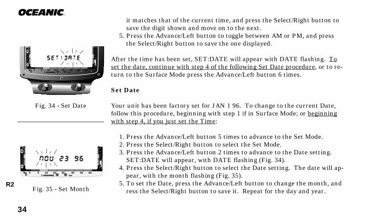
Set Date
Your unit has been factory set for JAN 1 96. To change to the current Date,follow this procedure, beginning with step 1 if in Surface Mode; or beginningwith step 4, if you just set the Time:
1. Press the Advance/Left button 5 times to advance to the Set Mode.2. Press the Select/Right button to select the Set Mode.3. Press the Advance/Left button 2 times to advance to the Date setting.
SET:DATE will appear, with DATE flashing (Fig. 34).4. Press the Select/Right button to select the Date setting. The date will ap-
pear, with the month flashing (Fig. 35).5. To set the Date, press the Advance/Left button to change the month, and
ress the Select/Right button to save it. Repeat for the day and year.Fig. 35 - Set Month
®
0 5 10 20 30 40 50 60
Fig. 34 - Set Date
®
0 5 10 20 30 40 50 60
R2

35
DataTrans PlusAfter the year has been set, SET: ALT will appear, with ALT flashing. To setthe Alternate display continue with step 4 of the following Set Alternate Dis-play procedure, or to return to the Surface Mode press the Advance/Left but-ton 5 times.
Set Alternate Display
Your unit has been factory set so the values of Temperature, Elapsed DiveTime, and Maximum Depth will be displayed continuously during the DiveMode. You can turn this Alternate display 'off' and have them appear onlywhen you wish to see them by depressing the Select/Right button during thedive. To turn the Alternate Display 'off', follow this procedure, beginning withstep 1 if in the Surface Mode, or beginning with step 4 if you just set the Date:
1. Press the Advance/Left button 5 times to advance to the Set Mode.2. Press the Select/Right button to select the Set Mode.3. Press the Advance/Left button 3 times to advance to the Alternate set-
ting. SET: ALT will appear with ALT flashing (Fig. 36).4. Press the Select/Right button to select the Alternate Display setting.
ALT: ON will appear with ON flashing (Fig. 37).5. Press the Advance/Left button to toggle between ON and Off, and press
the Select/Right button to select the one displayed.
After the Alternate display has been set, SET:UNITS will appear with UNITSflashing. To set the Units of Measure continue with step 4 of the following Set
®
0 5 10 20 30 40 50 60
Fig. 37 - Alt On/Off
Fig. 36 - Set Alt
®
0 5 10 20 30 40 50 60

36
®
Units of Measure procedure, or to return to the Surface Mode press the Ad-vance/Left button 4 times.
Set Units of Measure
You can choose between Imperial (PSI and Feet) and Metric (BAR and Meters)units of measure. Your unit has been factory set for FT and PSI. To change tometric units of measure, follow this procedure, beginning with step 1 if in theSurface Mode, or beginning with step 4 if you just set the Alternate Display:
1. Press the Advance/Left button 5 times to advance to the Set Mode.2. Press the Select/Right button to select the Set Mode.3. Press the Advance/Left button 4 times to advance to the Unit setting.
SET:UNIT will appear, with UNIT flashing (Fig. 38).4. Press the Select/Right button to select the Unit setting. PSI and FT will
appear, flashing (Fig. 39).5. Press the Advance/Left button to toggle between Imperial and Metric
units, and press the Select/Right button to accept the one displayed.
After the Units have been set, SET:ALRM will appear with ALRM flashing.To set the alarm values continue with step 4 of the Set Gas and Depth Alarmprocedure beginning on page 40, or to return to the Surface Mode press theAdvance/Left button 3 times.
®
DECOC.Z. C.Z.
PSI FT
O2NO DECO
0 5 10 20 30 40 50 60
Fig. 39 - Units
Fig. 38 - Set Units
®
0 5 10 20 30 40 50 60
R2

37
DataTrans PlusBREATHING GAS & DEPTH ALARM SET POINTS™
After planning each dive according to the no-decompression divetimes shown to be available in the Pre Dive Planning Sequence, Oce-anic strongly recommends that you utilize one of the greatest safetyfeatures the DataTrans Plus offers - the Gas & Depth Alarm settings.
While the DataTrans Plus uses the Audible Alarm, Message Box, andGraphic Diver Interface to automatically alert you whenever you en-ter a potentially dangerous situation, such as Decompression DiveMode, ascending too fast, running low on breathing gas, etc., theAlarm settings allow you to preset more conservative limits to betteravoid these situations.
Depth Alarm Set Point™
The Depth Alarm will alert you whenever you reach or exceed the maximumdepth Set Point value that you have chosen. Of course, if you set the DepthAlarm for a depth that is deeper than the no-decompression or decompressionlimits for that dive, you will first be alerted by other built-in alarms that youhave exceeded those limits before the Depth Alarm is activated.When the Depth Alarm is activated by reaching or exceeding your preset maxi-mum depth, the audible alarm will sound once per second, while the MessageBox flashes the words “TOO DEEP” (Fig. 40) until you ascend above the
®
DECOC.Z. C.Z.
PSI FT
O2NO DECO
0 5 10 20 30 40 50 60
Fig. 40 - Too Deep Message(60 FT Set Point)

38
®
Depth Alarm Set Point value. The Depth Alarm value may be set for depthsranging from 30-320 feet (9-97.5 meters), in 10 foot (3 & 3.5 meter) incre-ments. The setting that you choose for the Depth Alarm does not change thedisplayed limits of no-decompression dive time remaining.
Breathing Gas Alarm Set Point™
The Breathing Gas Alarm is an acoustic alert that indicates you are approach-ing a critical Breathing Gas Time Remaining. The Breathing Gas Alarm SetPoint refers to the surfacing tank pressure reserve of your choice, which maybe set for tank pressures ranging from 300 to 1000 psi (21 to 70 bar).
You will recall that Breathing Gas Time Remaining is the time that you canremain at your present depth and, following a safe ascent, still surface with aprescribed breathing gas reserve (identified here as the Breathing Gas AlarmSet Point).
When your Breathing Gas Time Remaining reaches 5 minutes, the Gas Alarmwill emit a double beep as a preliminary warning. If you allow your BreathingGas Time Remaining to decrease to zero, the tank pressure display will flashand the Message Box flashes the words "GAS ALARM" (Fig. 41) until you as-cend to a depth of 5 feet (1.5 meters) or less.
While an immediate safe ascent is called for if the Breathing Gas Time Re-Fig. 41 - Gas Alarm Message
®
DECOC.Z. C.Z.
PSI FT
O2NO DECO
0 5 10 20 30 40 50 60
39
DataTrans Plusmaining decreases to zero, there is no reason to panic. The DataTrans Plushas allowed for the breathing gas you will consume during a safe ascent, in-cluding decompression stops if they are required, and still provide the tankpressure reserve you have chosen, e.g., 300 psi (21 bar).
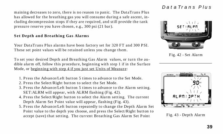
Set Depth and Breathing Gas Alarms
Your DataTrans Plus alarms have been factory set for 320 FT and 300 PSI.These set point values will be retained unless you change them.
To set your desired Depth and Breathing Gas Alarm values, or turn the au-dible alarm off, follow this procedure, beginning with step 1 if in the SurfaceMode, or beginning with step 4 if you just set Units of Measure:
1. Press the Advance/Left button 5 times to advance to the Set Mode.2. Press the Select/Right button to select the Set Mode.3. Press the Advance/Left button 5 times to advance to the Alarm setting.
SET:ALRM will appear, with ALRM flashing (Fig. 42).4. Press the Select/Right button to select the Alarm setting. The current
Depth Alarm Set Point value will appear, flashing (Fig. 43).5. Press the Advance/Left button repeatedly to change the Depth Alarm Set
Point value to the depth you choose, and press the Select/Right button toaccept (save) that setting. The current Breathing Gas Alarm Set Point Fig. 43 - Depth Alarm
®
DECOC.Z. C.Z.
FT
O2NO DECO
0 5 10 20 30 40 50 60
®
0 5 10 20 30 40 50 60
Fig. 42 - Set Alarm
40
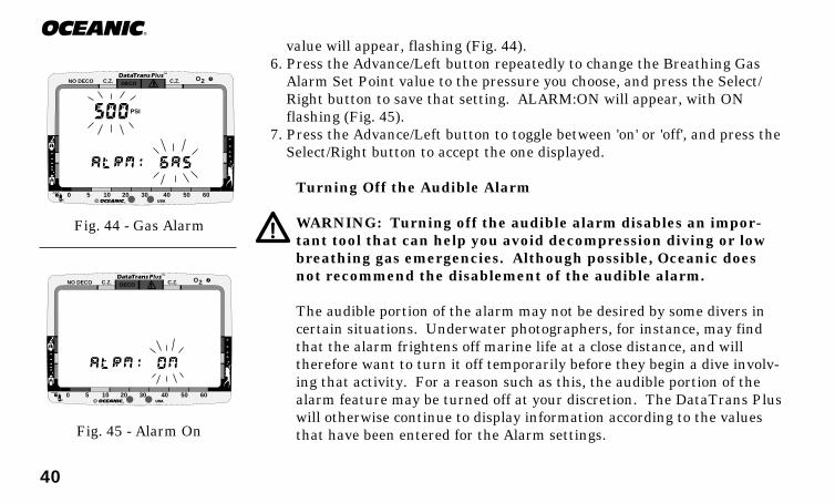
®
value will appear, flashing (Fig. 44).6. Press the Advance/Left button repeatedly to change the Breathing Gas
Alarm Set Point value to the pressure you choose, and press the Select/Right button to save that setting. ALARM:ON will appear, with ONflashing (Fig. 45).
7. Press the Advance/Left button to toggle between 'on' or 'off', and press theSelect/Right button to accept the one displayed.
Turning Off the Audible Alarm
WARNING: Turning off the audible alarm disables an impor-tant tool that can help you avoid decompression diving or lowbreathing gas emergencies. Although possible, Oceanic doesnot recommend the disablement of the audible alarm.
The audible portion of the alarm may not be desired by some divers incertain situations. Underwater photographers, for instance, may findthat the alarm frightens off marine life at a close distance, and willtherefore want to turn it off temporarily before they begin a dive involv-ing that activity. For a reason such as this, the audible portion of thealarm feature may be turned off at your discretion. The DataTrans Pluswill otherwise continue to display information according to the valuesthat have been entered for the Alarm settings.Fig. 45 - Alarm On
®
DECOC.Z. C.Z. O2NO DECO
0 5 10 20 30 40 50 60
®
DECOC.Z. C.Z.
PSI
O2NO DECO
0 5 10 20 30 40 50 60
Fig. 44 - Gas Alarm

41
DataTrans PlusAfter the Alarm values have been set, SET:LINK will appear with LINK flash-ing. To set the Transmitter Link code continue with step 4 of the followingLINKING procedure, or to return to the Surface Mode press the Advance/Leftbutton 2 times.
LINKING PROCEDURE
Your DataTrans Plus Display Module has been factory set with theTransmitter's serial number, or at serial number 999999 if no Transmitter waspurchased. If the DataTrans Plus linked automatically immediately followingactivation, there is no need to perform the Linking procedure. However, if theLink icon and pressure value of 00 PSI remained flashing on the screen, theLinking procedure must be performed before the Display Module can receivetank pressure data from the Transmitter.
The Linking procedure may also need to be performed in the event that yourDataTrans Plus Display Module or Transmitter has received factory service,and is returned to you with a different Linking code. You may also choose to“unlink” your Display Module from the Transmitter to use the Display Moduleas a stand alone computer, without its pressure integrated features, or to linkit to a Transmitter that has been purchased separately at a time in the future.
To set the Display Module with the link code (serial number of the Transmit-ter), follow this procedure beginning with step 1 if in the Surface Mode, or be-
RE
SP
ONSIBLE
DIV
ER
42
®
ginning with step 4 if you just set the Alarms:
1. Press the Advance/Left button 4 more times to advance to the Set Mode.2. Press the Select/Right button to select the Set Mode.3. Press the Advance/Left button 6 times to advance to the LINK setting.
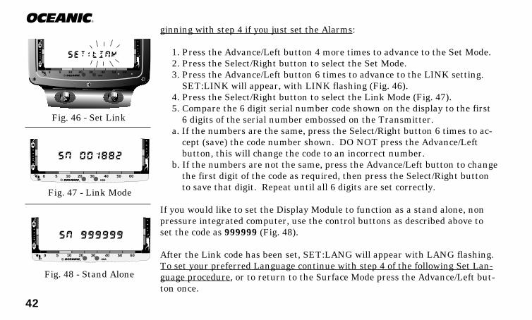
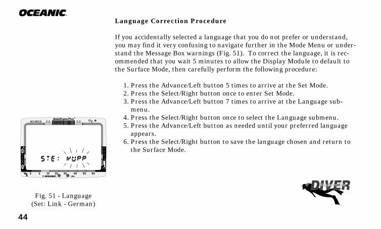
SET:LINK will appear, with LINK flashing (Fig. 46).4. Press the Select/Right button to select the Link Mode (Fig. 47).5. Compare the 6 digit serial number code shown on the display to the first
6 digits of the serial number embossed on the Transmitter.a. If the numbers are the same, press the Select/Right button 6 times to ac-
cept (save) the code number shown. DO NOT press the Advance/Leftbutton, this will change the code to an incorrect number.
b. If the numbers are not the same, press the Advance/Left button to changethe first digit of the code as required, then press the Select/Right buttonto save that digit. Repeat until all 6 digits are set correctly.
If you would like to set the Display Module to function as a stand alone, nonpressure integrated computer, use the control buttons as described above toset the code as 999999 (Fig. 48).
After the Link code has been set, SET:LANG will appear with LANG flashing.To set your preferred Language continue with step 4 of the following Set Lan-guage procedure, or to return to the Surface Mode press the Advance/Left but-ton once.
®
0 5 10 20 30 40 50 60
Fig. 48 - Stand Alone
®
0 5 10 20 30 40 50 60
Fig. 46 - Set Link
®
0 5 10 20 30 40 50 60
Fig. 47 - Link Mode

43
DataTrans PlusSet Language
The Message Box displays warning messages in the language that you choose -either English, Italian, German, Spanish, or French. The Mode Menu sys-tem is also displayed in the language selected, so it is very importantthat you do not accidentally change this setting to a language thatyou do not understand.
Your unit has been factory set for English. To change the language, followthis procedure beginning with step 1 if in the Surface Mode, or beginning withstep 4 if you just set the Link code:
1. Press the Advance/Left button 4 more times to advance to the Set Mode.2. Press the Select/Right button to select the Set Mode.3. Press the Advance/Left button 7 times to advance to the Language set-
ting. SET:LANG will appear, with LANG flashing (Fig. 49).4. Press the Select/Right button to select the Language setting. The default
setting ENGLISH will appear, flashing (Fig. 50).5. Press the Advance/Left button to scroll through the Language setting op-
tions until you arrive at the one you prefer.6. Be careful to ensure that the language selection flashing is the one that
you prefer before you press the Select/Right button.7. Press the Select/Right button to save the Language chosen and return to
the Surface Mode.Fig. 50 - Language
®
0 5 10 20 30 40 50 60
Fig. 49 - Set Language
®
0 5 10 20 30 40 50 60
44
®
Language Correction Procedure
If you accidentally selected a language that you do not prefer or understand,you may find it very confusing to navigate further in the Mode Menu or under-stand the Message Box warnings (Fig. 51). To correct the language, it is rec-ommended that you wait 5 minutes to allow the Display Module to default tothe Surface Mode, then carefully perform the following procedure:
1. Press the Advance/Left button 5 times to arrive at the Set Mode.2. Press the Select/Right button once to enter Set Mode.3. Press the Advance/Left button 7 times to arrive at the Language sub-
menu.4. Press the Select/Right button once to select the Language submenu.5. Press the Advance/Left button as needed until your preferred language
appears.6. Press the Select/Right button to save the language chosen and return to
the Surface Mode.
Fig. 51 - Language(Set: Link - German)
®
DECOC.Z. C.Z. O2NO DECO
0 5 10 20 30 40 50 60
Responsible

45
DataTrans Plus
PRE DIVEand
DIVE MODES

46
®
®
DE
CO
C.Z
.
C.Z
.
PS
I
FTO2
NO
DE
CO
05
1020
3040
5060
®
DECO
C.Z.
C.Z.
PSI
FT
O 2
NO DECO
0
5
10
20
30
40
50
60
®
DECO
C.Z.
C.Z.PSI
FT
O2
NO DECO
0
5
10
20
30
40
50
60
Poor reception distance.(Greater than 3 feet)
Poorreceptionarea.
Poorreceptionarea.
®
DEC
O
C.Z
.
C.Z
.
PSI
FT
O2
NO
DEC
O
0
510
2030
4050
60
Bestreceptionzone.
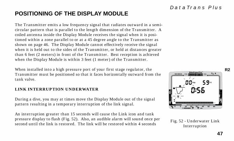
47
DataTrans Plus
®
DECOC.Z. C.Z.
PSI FT
O2NO DECO
0 5 10 20 30 40 50 60
POSITIONING OF THE DISPLAY MODULE
The Transmitter emits a low frequency signal that radiates outward in a semi-circular pattern that is parallel to the length dimension of the Transmitter. Acoiled antenna inside the Display Module receives the signal when it is posi-tioned within a zone parallel to or at a 45 degree angle to the Transmitter asshown on page 46. The Display Module cannot effectively receive the signalwhen it is held out to the sides of the Transmitter, or held at distances greaterthan 6 feet (2 meters) in front of the Transmitter. Best reception is achievedwhen the Display Module is within 3 feet (1 meter) of the Transmitter.
When installed into a high pressure port of your first stage regulator, theTransmitter must be positioned so that it faces horizontally outward from thetank valve.
LINK INTERRUPTION UNDERWATER
During a dive, you may at times move the Display Module out of the signalpattern resulting in a temporary interruption of the link signal.
An interruption greater than 15 seconds will cause the Link icon and tankpressure display to flash (Fig. 52). Also, an audible alarm will sound once persecond until the link is restored. The link will be restored within 4 seconds
Fig. 52 - Underwater LinkInterruption
R2
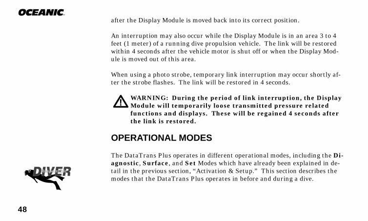
48
®
after the Display Module is moved back into its correct position.
An interruption may also occur while the Display Module is in an area 3 to 4feet (1 meter) of a running dive propulsion vehicle. The link will be restoredwithin 4 seconds after the vehicle motor is shut off or when the Display Mod-ule is moved out of this area.
When using a photo strobe, temporary link interruption may occur shortly af-ter the strobe flashes. The link will be restored in 4 seconds.
WARNING: During the period of link interruption, the DisplayModule will temporarily loose transmitted pressure relatedfunctions and displays. These will be regained 4 seconds afterthe link is restored.
OPERATIONAL MODES
The DataTrans Plus operates in different operational modes, including the Di-agnostic, Surface, and Set Modes which have already been explained in de-tail in the previous section, “Activation & Setup.” This section describes themodes that the DataTrans Plus operates in before and during a dive.
Responsible

49
DataTrans PlusFO2 MODE
WARNING: The percentage of oxygen (FO2) in the nitrox mixbeing used must be set 'before each' nitrox dive.
The DataTrans Plus can be used either as an Air computer or a Nitrox com-puter. After activation, the Display Module will operate as an Air computerwithout displaying information associated with oxygen calculations, unless it isset for a percentage of oxygen (FO2) other than Air (numerical value between21 and 50 %).
FO2 Set for Air
If you are using 'Air' as your breathing gas, you can verify that 'Air' is the FO2value by performing the following procedure beginning in the Surface Mode:
1. Press the Advance/Left button once to enter the Mode Menu. MODE:FO2 will appear, with FO2 flashing (Fig. 53).
2. Press the Select/Right button once to select the FO2 Mode. FO2 Air willappear, with Air flashing (Fig. 54).
3. Press the Select/Right once to accept Air as the setting. MODE:PLANwill appear with PLAN flashing.
4. Press the Advance/Left button 5 times to return to the Surface Mode.
Fig. 53 - FO2 Mode
Fig. 54 - Air Setting
®
DECOC.Z. C.Z. O2NO DECO
0 5 10 20 30 40 50 60
®
0 5 10 20 30 40 50 60

50
®
When set with an FO2 value of 'Air', the DataTrans Plus will perform calcula-tions the same as if FO2 were set for 21% oxygen, internally accounting foroxygen loading for any subsequent Nitrox dives. However, oxygen related dis-plays, warnings, and the O2 bar graph will not appear on the LCD display forthat dive (Fig. 55), or subsequent dives, unless FO2 is set for a numerical value(21 to 50 %).
Setting FO2 for a Nitrox Dive
You can program the DataTrans Plus for nitrogen-oxygen (nitrox) mixtures of21% to 50% oxygen (O2) before each nitrox dive. If FO2 is set at a value of21%, the unit will remain set as a '21% nitrox computer' for subsequent nitroxdives until FO2 is set to a higher value, or the Display Module automaticallyturns off. Once FO2 is set to a value 'greater than 21%' to match the nitroxmix being used for that nitrox dive, the FO2 value displayed during the FO2Mode that is accessible 10 minutes after that dive will be 50% (Fig. 56).
FO2 must be reset for each repetitive nitrox dive, or the value will automati-cally default to 50 and the dives will be calculated based on 50% O2 for oxygencalculations and 21% O2 (79% nitrogen) for nitrogen calculations. Once a diveis made with the DataTrans Plus set as a nitrox computer (FO2 set for a nu-merical value), the unit cannot be programmed to operate as an 'Air' computeruntil 24 hours after the last dive. 'Air' will not be displayed as an option in theFO2 Mode.
Fig. 55 - Dive Mode (Air)
Fig. 56 - FO2 Default(after nitrox dive)
®
DECOC.Z. C.Z.
PSI FT
O2NO DECO
0 5 10 20 30 40 50 60
®
DECOC.Z. C.Z. O2NO DECO
0 5 10 20 30 40 50 60
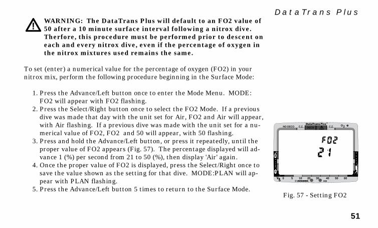
51
DataTrans PlusWARNING: The DataTrans Plus will default to an FO2 value of50 after a 10 minute surface interval following a nitrox dive.Therfore, this procedure must be performed prior to descent oneach and every nitrox dive, even if the percentage of oxygen inthe nitrox mixtures used remains the same.
To set (enter) a numerical value for the percentage of oxygen (FO2) in yournitrox mix, perform the following procedure beginning in the Surface Mode:
1. Press the Advance/Left button once to enter the Mode Menu. MODE:FO2 will appear with FO2 flashing.
2. Press the Select/Right button once to select the FO2 Mode. If a previousdive was made that day with the unit set for Air, FO2 and Air will appear,with Air flashing. If a previous dive was made with the unit set for a nu-merical value of FO2, FO2 and 50 will appear, with 50 flashing.
3. Press and hold the Advance/Left button, or press it repeatedly, until theproper value of FO2 appears (Fig. 57). The percentage displayed will ad-vance 1 (%) per second from 21 to 50 (%), then display 'Air' again.
4. Once the proper value of FO2 is displayed, press the Select/Right once tosave the value shown as the setting for that dive. MODE:PLAN will ap-pear with PLAN flashing.
5. Press the Advance/Left button 5 times to return to the Surface Mode.Fig. 57 - Setting FO2
®
DECOC.Z. C.Z. O2NO DECO
0 5 10 20 30 40 50 60
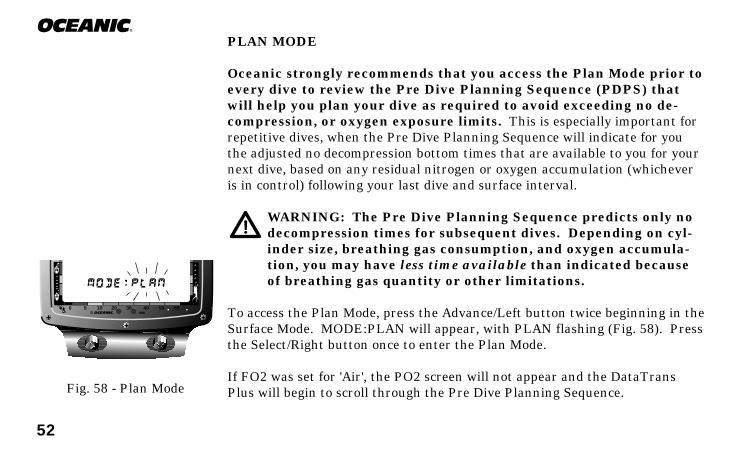
52
®
PLAN MODE
Oceanic strongly recommends that you access the Plan Mode prior toevery dive to review the Pre Dive Planning Sequence (PDPS) thatwill help you plan your dive as required to avoid exceeding no de-compression, or oxygen exposure limits. This is especially important forrepetitive dives, when the Pre Dive Planning Sequence will indicate for youthe adjusted no decompression bottom times that are available to you for yournext dive, based on any residual nitrogen or oxygen accumulation (whicheveris in control) following your last dive and surface interval.
WARNING: The Pre Dive Planning Sequence predicts only nodecompression times for subsequent dives. Depending on cyl-inder size, breathing gas consumption, and oxygen accumula-tion, you may have less time available than indicated becauseof breathing gas quantity or other limitations.
To access the Plan Mode, press the Advance/Left button twice beginning in theSurface Mode. MODE:PLAN will appear, with PLAN flashing (Fig. 58). Pressthe Select/Right button once to enter the Plan Mode.
If FO2 was set for 'Air', the PO2 screen will not appear and the DataTransPlus will begin to scroll through the Pre Dive Planning Sequence.Fig. 58 - Plan Mode
®
0 5 10 20 30 40 50 60

53
DataTrans PlusIf FO2 was set for a numerical value, FO2 and the value set will appear as thefirst screen (Fig. 59), followed by a screen showing the maximum depth thatcan be achieved for an oxygen partial pressure of 1.60 ATA for that FO2 (Fig.60).
The DataTrans Plus then scrolls through the Pre Dive Planning Sequence(PDPS), displaying a sequence of depths from 30 to 160 feet (9 to 48 meters) in10 foot (3 meter) increments. With each depth display, you will see either 'pre-dicted' no decompression limits based upon your previous dive profiles (if cal-culated to be nitrogen controlled), or 'predicted' oxygen tolerance limits basedupon either a single dive oxygen dose or your 24 hour accumulation of oxygen(if calculated to be oxygen controlled).
Information displayed includes Previous Dive #, Depth, Dive Time available atthat depth (which includes descent time at a rate of 120 ft/min), Plan Modeicon, and the message MODE:PLAN.
No decompression times are only displayed for depths where there is at least 3minutes of dive time available at the depth, taking into account a descent rateof 120 feet (36 meters) per minute. Depths greater than the maximum depththat can be achieved with a partial pressure of oxygen (PO2) of 1.60 ATA willnot be displayed.
Fig. 60 - Max Allowed Depth
Fig. 59 - FO2 Value Set
®
DECOC.Z. C.Z. O2NO DECO
0 5 10 20 30 40 50 60
®
DECOC.Z. C.Z.
FT
O2NO DECO
0 5 10 20 30 40 50 60
MAX
R2
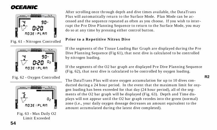
54
®
After scrolling once through depth and dive times available, the DataTransPlus will automatically return to the Surface Mode. Plan Mode can be ac-cessed and the sequence repeated as often as you choose. If you wish to inter-rupt the Pre Dive Planning Sequence to return to the Surface Mode, you maydo so at any time by pressing either control button.
Prior to a Repetitive Nitrox Dive
If the segments of the Tissue Loading Bar Graph are displayed during the PreDive Planning Sequence (Fig 61), that next dive is calculated to be controlledby nitrogen loading.
If the segments of the O2 bar graph are displayed Pre Dive Planning Sequence(Fig. 62), that next dive is calculated to be controlled by oxygen loading.
The DataTrans Plus will store oxygen accumulation for up to 10 dives con-ducted during a 24 hour period. In the event that the maximum limit for oxy-gen loading has been exceeded for that day (24 hour period), all of the seg-ments of the O2 bar graph will be displayed (Fig. 63). Depth and Time dis-plays will not appear until the O2 bar graph recedes into the green (normal)zone (i.e., your daily oxygen doseage decreases an amount equivalent to theamount accumulated during the latest dive completed).
DECOC.Z. C.Z.
FT
O2NO DECO
Fig. 63 - Max Daily O2Limit Exceeded
Fig. 61 - Nitrogen Controlled
DECOC.Z. C.Z.
FT
O2NO DECO
DECOC.Z. C.Z. O2NO DECO
Fig. 62 - Oxygen Controlled R2
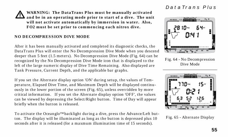
55
DataTrans PlusWARNING: The DataTrans Plus must be manually activatedand be in an operating mode prior to start of a dive. The unitwill not activate automatically by immersion in water. Also,FO2 must be set prior to commencing each nitrox dive.
NO DECOMPRESSION DIVE MODE
After it has been manually activated and completed its diagnostic checks, theDataTrans Plus will enter the No Decompression Dive Mode when you descenddeeper than 5 feet (1.5 meters). No Decompression Dive Mode (Fig. 64) can berecognized by the No Decompression Dive Mode icon that is displayed to theleft of the large numeric display of Dive Time Remaining. Also displayed areTank Pressure, Current Depth, and the applicable bar graphs.
If you set the Alternate display option 'ON' during setup, the values of Tem-perature, Elapsed Dive Time, and Maximum Depth will be displayed continu-ously in the lower portion of the screen (Fig. 65), unless overridden by morecritical information. If you set the Alternate display option 'OFF', the valuescan be viewed by depressing the Select/Right button. Time of Day will appearbriefly when the button is released.
To activate the Oceanglo™ backlight during a dive, press the Advance/Left but-ton. The display will be illuminated as long as the button is depressed plus 10seconds after it is released (for a maxmum illumination time of 15 seconds).
Fig. 65 - Alternate Display
Fig. 64 - No DecompressionDive Mode
®
DECOC.Z. C.Z.
PSI FT
O2NO DECO
0 5 10 20 30 40 50 60
®
DECOC.Z. C.Z.
PSI FT
O2NO DECO
0 5 10 20 30 40 50 60

56
®
As your depth and elapsed dive time increase, the Tissue Loading Bar Graphwill fill with segments (green to red) to represent the absorption of nitrogen;and if FO2 was set for a value other than 'Air', the O2 bar graph will fill withsegments (green to red) to represent oxygen accumulation for that dive, or 24hour period, whichever is greater. The Gas Time Remaining bar graph willrecede from green to red as breathing gas time remaining decreases from 60 to0 minutes. Segments of the Breathing Gas Consumption and Variable AscentRate Indicator bar graphs fill (and recede) as their respective rates increase(and decrease) throughout the dive.
WARNING: Every effort should be made to keep all of the bargraphs in the green throughout your dives to reduce your riskof exposure to decompression sickness and oxygen toxicity.
DECOMPRESSION DIVE MODE
The DataTrans Plus provides information that will help you avoid, or if neces-sary, manage emergency decompression.
The Decompression Dive Mode activates when the No Decompression Limitsare exceeded and the Tissue Loading Bar Graph enters the red decompressionzone (Fig. 66).
Fig. 66 - DecompressionDive Mode
®
DECOC.Z. C.Z.
PSI FT
O2NO DECO
0 5 10 20 30 40 50 60
Deco Zone
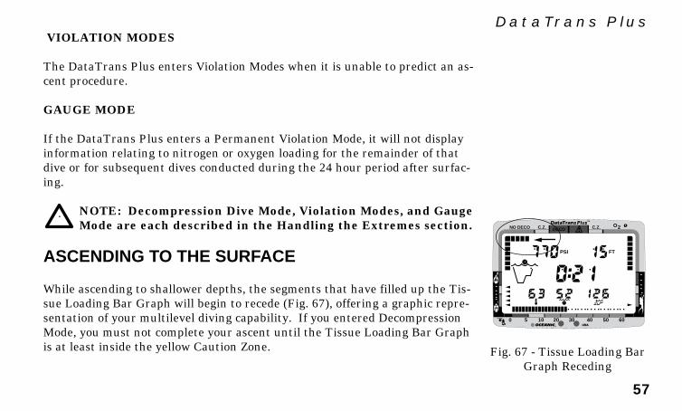
57
DataTrans Plus
®
DECOC.Z. C.Z.
PSI FT
O2NO DECO
0 5 10 20 30 40 50 60
VIOLATION MODES
The DataTrans Plus enters Violation Modes when it is unable to predict an as-cent procedure.
GAUGE MODE
If the DataTrans Plus enters a Permanent Violation Mode, it will not displayinformation relating to nitrogen or oxygen loading for the remainder of thatdive or for subsequent dives conducted during the 24 hour period after surfac-ing.
NOTE: Decompression Dive Mode, Violation Modes, and GaugeMode are each described in the Handling the Extremes section.
ASCENDING TO THE SURFACE
While ascending to shallower depths, the segments that have filled up the Tis-sue Loading Bar Graph will begin to recede (Fig. 67), offering a graphic repre-sentation of your multilevel diving capability. If you entered DecompressionMode, you must not complete your ascent until the Tissue Loading Bar Graphis at least inside the yellow Caution Zone. Fig. 67 - Tissue Loading Bar
Graph Receding
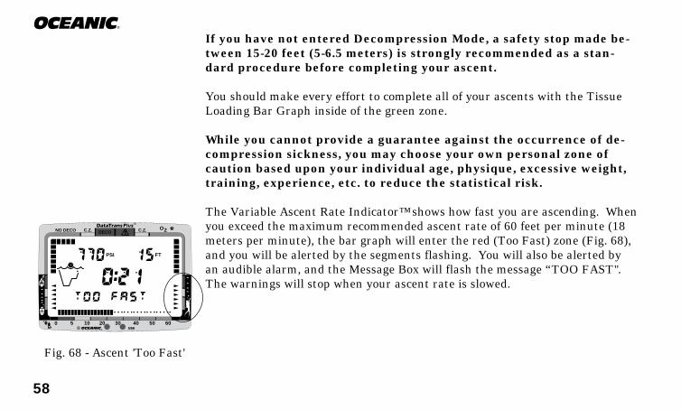
58
®
If you have not entered Decompression Mode, a safety stop made be-tween 15-20 feet (5-6.5 meters) is strongly recommended as a stan-dard procedure before completing your ascent.
You should make every effort to complete all of your ascents with the TissueLoading Bar Graph inside of the green zone.
While you cannot provide a guarantee against the occurrence of de-compression sickness, you may choose your own personal zone ofcaution based upon your individual age, physique, excessive weight,training, experience, etc. to reduce the statistical risk.
The Variable Ascent Rate Indicator™ shows how fast you are ascending. Whenyou exceed the maximum recommended ascent rate of 60 feet per minute (18meters per minute), the bar graph will enter the red (Too Fast) zone (Fig. 68),and you will be alerted by the segments flashing. You will also be alerted byan audible alarm, and the Message Box will flash the message “TOO FAST".The warnings will stop when your ascent rate is slowed.
Fig. 68 - Ascent 'Too Fast'
®
DECOC.Z. C.Z.
PSI FT
O2NO DECO
0 5 10 20 30 40 50 60
59
DataTrans PlusALTITUDE DIVING
The mathematical model within the DataTrans Plus accounts for the reducedNo Decompression dive time available at higher elevations based on NOAA(National Oceanic and Atmospheric Administration) guidelines. When divingin high altitude lakes or rivers from 2,000 to 14,000 feet (610 to 4,268 meters),the DataTrans Plus will adjust automatically, providing corrected depth andreduced No Decompression and Oxygen Exposure times.
Also, when above 2,000 feet (610 meters), depth calibration is automaticallychanged to read in feet of freshwater rather than feet of seawater.
NOTE: If activated above 14,000 feet (4,268 meters), a message"TOO HIGH" will appear and the unit will shut off.
More about altitude diving is presented in the Reference section.
WARNING: Until it has shut itself off, you must not use theDataTrans Plus at a different altitude than the altitude whereit was originally activated. Doing so will result in an errorequal to the difference in barometric pressure, and possibly afalse dive mode with erroneous data.
Be a -RESPONSIBLE DIVER
at all times.
RE
SP
ONSIBLE
DIV
ER

60
®
(This page intentionally left blank.)

61
DataTrans Plus
POSTDIVE
MODES

62
®
®
DECOC.Z. C.Z.
PSI FT
O2NO DECO
0 5 10 20 30 40 50 60
POST DIVE SURFACE MODE
When you ascend to 3 feet (1 meter) or shallower, the DataTrans Plus will en-ter Surface Mode (Fig. 69) and begin counting your surface interval.
TRANSITION PERIOD
The first 10 minutes is, in affect, a transition period during which time:
• The main time display starts counting Surface Interval (colon flashing).• The Surface Mode icon will appear (flashing).• The Tissue Loading Bar Graph will indicate current nitrogen loading.• The O2 bar graph will indicate current oxygen loading, if the dive was a
nitrox dive (FO2 set for a numerical value).• Temperature and Time of Day will also be displayed.
If you descend during the 10 minute transition period, time underwater will beconsidered a continuation of that dive. The time at the surface (if less than 10minutes) will not be added as Elapsed Dive Time. During the 10 minute tran-sition period, the Log Mode is accessible in the Mode Menu and will displaythat dive's data, however, the data will not be stored in the unit's memory untilthe 10 minute period on the surface is completed. No other modes are acces-sible in the Mode Menu during the 10 minute transition period.
Fig. 69 - Post DiveSurface Mode (<10 min)

63
DataTrans PlusOnce 10 minutes have elapsed, the Surface Mode icon and Surface Intervaltime display colon will stop flashing (Fig. 70) indicating that the dive and tran-sition period are completed, and a subsequent descent will be considered a newdive. Other information will continue to be displayed as described above andyou will have full access to the Mode Menu.
FO2 MODE
If the DataTrans Plus was set for FO2 of 'Air' or 21% prior to the dive, it willstay set for 'Air' or 21%, respectively, unless you reset it to a higher numericvalue prior to the next dive. If it was set for a numeric value of FO2 greaterthan 21% (22 to 50 %) prior to the dive, the FO2 value displayed after the divewill be 50 % (Fig. 71) and subsequent dives will be calculated based on 50%oxygen for oxygen calculations and 21% oxygen (79% nitrogen) for nitrogencalculations, unless you set FO2 for another value.
Remember!! You must set the FO2 to match the specific nitrox mixfor each nitrox dive, even if the percentage of oxygen in the mix isthe same as the previous.
PLAN MODE
When you access the Plan Mode after a dive, the FO2 screen will show the FO2set point value that you entered for the next dive. The PO2 screen will show
Fig. 70 - Surface Mode(> 10 min)
Fig. 71 - FO2 Default
®
DECOC.Z. C.Z. O2NO DECO
0 5 10 20 30 40 50 60
®
DECOC.Z. C.Z.
PSI FT
O2NO DECO
0 5 10 20 30 40 50 60
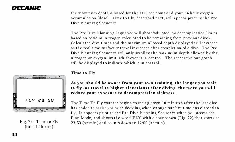
64
®
the maximum depth allowed for the FO2 set point and your 24 hour oxygenaccumulation (dose). Time to Fly, described next, will appear prior to the PreDive Planning Sequence.
The Pre Dive Planning Sequence will show 'adjusted' no decompression limitsbased on residual nitrogen calculated to be remaining from previous dives.Calculated dive times and the maximum allowed depth displayed will increaseas the real time surface interval increases after completion of a dive. The PreDive Planning Sequence will only scroll to the maximum depth allowed by thenitrogen or oxygen limit, whichever is in control. The respective bar graphwill be displayed to indicate which is in control.
Time to Fly
As you should be aware from your own training, the longer you waitto fly (or travel to higher elevations) after diving, the more you willreduce your exposure to decompression sickness.
The Time To Fly counter begins counting down 10 minutes after the last divehas ended to assist you with deciding when enough surface time has elapsed tofly. It appears prior to the Pre Dive Planning Sequence when you access thePlan Mode, and shows the word 'FLY' with a countdown (Fig. 72) that starts at23:50 (hr:min) and counts down to 12:00 (hr:min).Fig. 72 - Time to Fly
(first 12 hours)
®
DECOC.Z. C.Z. O2NO DECO
0 5 10 20 30 40 50 60
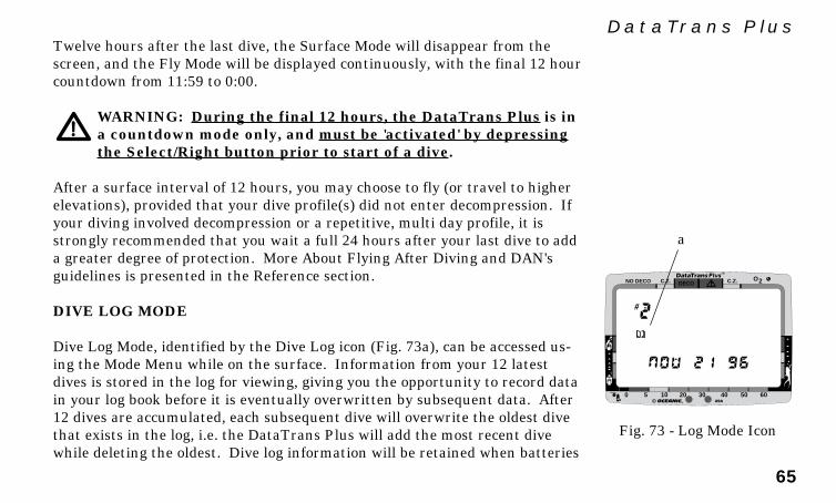
65
DataTrans PlusTwelve hours after the last dive, the Surface Mode will disappear from thescreen, and the Fly Mode will be displayed continuously, with the final 12 hourcountdown from 11:59 to 0:00.
WARNING: During the final 12 hours, the DataTrans Plus is ina countdown mode only, and must be 'activated' by depressingthe Select/Right button prior to start of a dive.
After a surface interval of 12 hours, you may choose to fly (or travel to higherelevations), provided that your dive profile(s) did not enter decompression. Ifyour diving involved decompression or a repetitive, multi day profile, it isstrongly recommended that you wait a full 24 hours after your last dive to adda greater degree of protection. More About Flying After Diving and DAN'sguidelines is presented in the Reference section.
DIVE LOG MODE
Dive Log Mode, identified by the Dive Log icon (Fig. 73a), can be accessed us-ing the Mode Menu while on the surface. Information from your 12 latestdives is stored in the log for viewing, giving you the opportunity to record datain your log book before it is eventually overwritten by subsequent data. After12 dives are accumulated, each subsequent dive will overwrite the oldest divethat exists in the log, i.e. the DataTrans Plus will add the most recent divewhile deleting the oldest. Dive log information will be retained when batteries
Fig. 73 - Log Mode Icon
®
DECOC.Z. C.Z. O2NO DECO
0 5 10 20 30 40 50 60
a
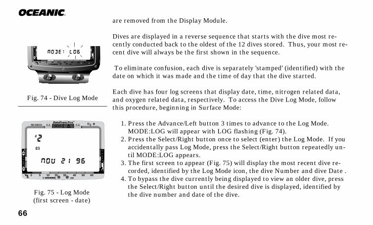
66
®
are removed from the Display Module.
Dives are displayed in a reverse sequence that starts with the dive most re-cently conducted back to the oldest of the 12 dives stored. Thus, your most re-cent dive will always be the first shown in the sequence.
To eliminate confusion, each dive is separately 'stamped' (identified) with thedate on which it was made and the time of day that the dive started.
Each dive has four log screens that display date, time, nitrogen related data,and oxygen related data, respectively. To access the Dive Log Mode, followthis procedure, beginning in Surface Mode:
1. Press the Advance/Left button 3 times to advance to the Log Mode.MODE:LOG will appear with LOG flashing (Fig. 74).
2. Press the Select/Right button once to select (enter) the Log Mode. If youaccidentally pass Log Mode, press the Select/Right button repeatedly un-til MODE:LOG appears.
3. The first screen to appear (Fig. 75) will display the most recent dive re-corded, identified by the Log Mode icon, the dive Number and dive Date .
4. To bypass the dive currently being displayed to view an older dive, pressthe Select/Right button until the desired dive is displayed, identified bythe dive number and date of the dive.Fig. 75 - Log Mode
(first screen - date)
®
DECOC.Z. C.Z. O2NO DECO
0 5 10 20 30 40 50 60
Fig. 74 - Dive Log Mode
®
0 5 10 20 30 40 50 60

67
DataTrans Plus5. Press the Advance/Left button once, to display the Time of Day (Fig. 76)
when the dive started.6. Press the Advance/Left button once more to view the information associ-
ated with nitrogen (Fig. 77). Displayed will be: Log Mode icon, dive Num-ber, Surface Time between that dive and the one previous to it, lowestwater Temperature during the dive, Elapsed Dive Time, and MaximumDepth. If the dive shown in the log display was the only one of the day,Surface Time will represent the time between initial activation and thebeginning of the first dive. Also shown will be the tissue nitrogen loadingat the time you surfaced from the dive (Tissue Loading Bar Graph), themaximum rate of breathing gas consumption (Gas Consumption Indica-tor), and the maximum rate of ascent at any time during the dive (Vari-able Ascent Rate Indicator).
7. Press the Advance/Left button once to view the information associatedwith oxygen (Fig. 78). Displayed will be: Log Mode icon, dive Number,FO2 symbol and the value that FO2 was set at for the dive. If FO2 wasset for a value other than 'Air', the PO2 symbol and value of the maxi-mum partial pressure of oxygen attained during the dive will also be dis-played. Also shown will be the oxygen loading (O2 bar graph) at the timeyou surfaced from the dive (maximum for that dive or 24 hour period,whichever was greater at the time). The O2 bar graph will also displaythe segment that represents the maximum level of oxygen exposure(dose) that you achieved during that dive.
8. Press either button to advance to the first screen (Date) of the next diveFig. 78 - Log Mode
(fourth screen - oxygen)
DECOC.Z. C.Z. O2NO DECO
Fig. 77 - Log Mode(third screen - nitrogen)
DECOC.Z. C.Z. O2NO DECO
Fig. 76 - Log Mode(second screen - time)
DECOC.Z. C.Z. O2NO DECO
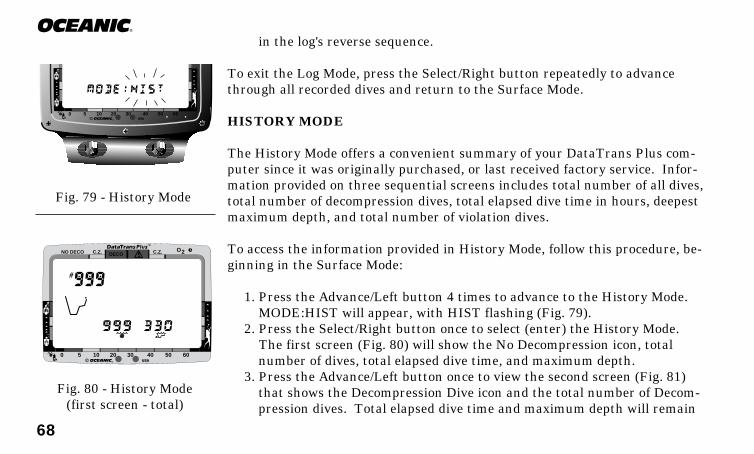
68
®
in the log's reverse sequence.
To exit the Log Mode, press the Select/Right button repeatedly to advancethrough all recorded dives and return to the Surface Mode.
HISTORY MODE
The History Mode offers a convenient summary of your DataTrans Plus com-puter since it was originally purchased, or last received factory service. Infor-mation provided on three sequential screens includes total number of all dives,total number of decompression dives, total elapsed dive time in hours, deepestmaximum depth, and total number of violation dives.
To access the information provided in History Mode, follow this procedure, be-ginning in the Surface Mode:
1. Press the Advance/Left button 4 times to advance to the History Mode.MODE:HIST will appear, with HIST flashing (Fig. 79).
2. Press the Select/Right button once to select (enter) the History Mode. The first screen (Fig. 80) will show the No Decompression icon, total
number of dives, total elapsed dive time, and maximum depth.3. Press the Advance/Left button once to view the second screen (Fig. 81)
that shows the Decompression Dive icon and the total number of Decom-pression dives. Total elapsed dive time and maximum depth will remain
Fig. 80 - History Mode(first screen - total)
Fig. 79 - History Mode
®
0 5 10 20 30 40 50 60
®
DECOC.Z. C.Z. O2NO DECO
0 5 10 20 30 40 50 60

69
DataTrans Pluson display.
4. Press the Advance/Left button once again to view the third and finalscreen (Fig. 82) that shows the Dive Mode icon and the total number ofdives during which the DataTrans Plus entered a Violation Mode.
5. Press either button to return to the Surface Mode.
NOTE: Previous unit history will be erased whenever yourDataTrans Plus receives factory service.
EXTERNAL ACCESS MODE (EACC)
Using special infrared linking hardware and a unique PC software program,data from your dives can be downloaded (copied) from your DataTrans Plusinto an IBM compatible personal computer program running on a Windows®
3.x or Windows® 95 operating system. Instructions for performing the inter-face and download are provided with the hardware and software package thatis available separately from your Authorized Oceanic Dealer. Ask forOceanLog™ for DataTrans Plus.
The OceanLog™ software program provides dive profile data, and nitrogen andoxygen loading information that was sampled throughout the dives that aredownloaded..
Once you have acquired your OceanLink™ package, to access the External Ac-Fig. 82 - History Mode
(third screen - violation)
Fig. 81 - History Mode(second screen - deco)
®
DECOC.Z. C.Z. O2NO DECO
0 5 10 20 30 40 50 60
®
DECOC.Z. C.Z. O2NO DECO
0 5 10 20 30 40 50 60
R2
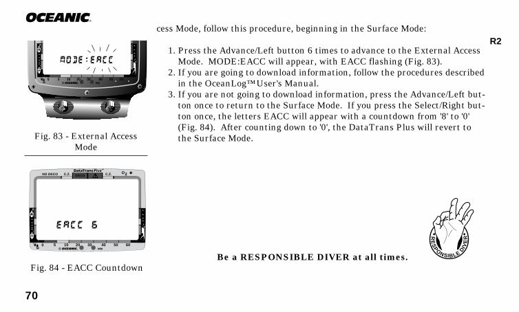
70
®
®
0 5 10 20 30 40 50 60
cess Mode, follow this procedure, beginning in the Surface Mode:
1. Press the Advance/Left button 6 times to advance to the External AccessMode. MODE:EACC will appear, with EACC flashing (Fig. 83).
2. If you are going to download information, follow the procedures describedin the OceanLog™ User's Manual.
3. If you are not going to download information, press the Advance/Left but-ton once to return to the Surface Mode. If you press the Select/Right but-ton once, the letters EACC will appear with a countdown from '8' to '0'(Fig. 84). After counting down to '0', the DataTrans Plus will revert tothe Surface Mode.
Fig. 84 - EACC Countdown
Fig. 83 - External AccessMode
®
DECOC.Z. C.Z. O2NO DECO
0 5 10 20 30 40 50 60
RE
SP
ONSIBLE
DIV
ER
Be a RESPONSIBLE DIVER at all times.
R2

71
DataTrans Plus
HANDLINGTHE
EXTREMES
72
®
EMERGENCY DECOMPRESSION
There are few legitimate excuses for making unplanned Decompression dives,and the consequences of this type of diving can be severe. Decompression div-ing requires special training and support. The DataTrans Plus is intendedfor use by recreational divers not engaged in intentional decompres-sion diving. Decompression features are provided only for emer-gency situations. By entering decompression, you automatically impose a“ceiling” above you which you cannot immediately ascend beyond, denying youfree access to the surface.
Professional military and commercial divers plan ahead for this situation byensuring that they have complete surface support, including a redundantbreathing gas supply for emergencies. They also navigate very carefullythroughout their dive to ensure that they begin and complete their ascentwhile maintaining contact with a rope or a line to the surface. This is neces-sary for making a well controlled ascent. The DataTrans Plus is not in-tended for use by military or commercial divers.
By making an unplanned Decompression dive without the necessary prepara-tion and training, you will have placed yourself in an unnecessarily danger-ous situation. Consider also, that one mistake can quickly be compounded byseveral others.
DECOMPRESSIONRULES
ARE NOT MEANTTO BE BENT
Responsible

73
DataTrans Plus
®
DECOC.Z. C.Z.
PSI FT
O2NO DECO
0 5 10 20 30 40 50 60
The DataTrans Plus is a sophisticated instrument designed with capabilitiesthat go beyond the range of recreational diving with compressed air. Itshould not be considered, however, that these built-in capabilitiesprovide any implied approval or consent from Oceanic for individu-als to exceed the defined limits of recreational dive profiles, asagreed on by all internationally recognized training agencies.
Decompression diving should therefore be strictly avoided. TheDataTrans Plus is designed to help you by providing a complete representationof how close you are to entering decompression. In the event that you do inad-vertently enter decompression, the red zone of the Tissue Loading Bar Graph(Fig. 85), the DataTrans Plus can provide you with limited information to helpyou ascend to the surface, if you follow the instructions given in this section.
Oceanic strongly recommends that you avoid entering decompres-sion, and reminds you that decompression diving requires specialtraining.
The DataTrans Plus cannot provide you with a backup breathing gassupply for emergencies or the ascent line you will need, and decom-pression diving greatly increases your risk of decompression sick-ness.
Fig. 85 - DecompressionMode
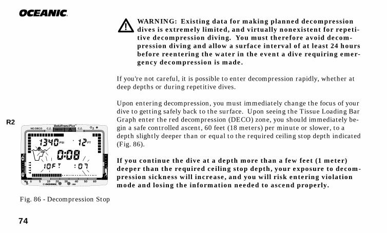
74
®
®
DECOC.Z. C.Z.
PSI FT
O2NO DECO
0 5 10 20 30 40 50 60
WARNING: Existing data for making planned decompressiondives is extremely limited, and virtually nonexistent for repeti-tive decompression diving. You must therefore avoid decom-pression diving and allow a surface interval of at least 24 hoursbefore reentering the water in the event a dive requiring emer-gency decompression is made.
If you're not careful, it is possible to enter decompression rapidly, whether atdeep depths or during repetitive dives.
Upon entering decompression, you must immediately change the focus of yourdive to getting safely back to the surface. Upon seeing the Tissue Loading BarGraph enter the red decompression (DECO) zone, you should immediately be-gin a safe controlled ascent, 60 feet (18 meters) per minute or slower, to adepth slightly deeper than or equal to the required ceiling stop depth indicated(Fig. 86).
If you continue the dive at a depth more than a few feet (1 meter)deeper than the required ceiling stop depth, your exposure to decom-pression sickness will increase, and you will risk entering violationmode and losing the information needed to ascend properly.
Fig. 86 - Decompression Stop
R2

75
DataTrans PlusGAS TIME REMAINING DURING DECOMPRESSION
Breathing Gas Time Remaining will fluctuate throughout your dive, decreas-ing as you dive deeper or breath heavier, and increasing as you ascend to shal-lower depths or relax your breathing efforts. If you inadvertently exceed nodecompression limits, the DataTrans Plus will provide critical information re-garding your remaining breathing gas supply.
Once you enter Decompression Mode, you will need to refer to the Gas TimeRemaining bar graph for Breathing Gas Dive Time Remaining information.
When Breathing Gas Time Remaining decreases to 5 minutes, the tank pres-sure numerals will flash and a Double Beep will sound (Fig. 87). This meansthat only 5 minutes remain before your breathing gas supply will be reduced tothe minimum level necessary to perform the required decompression stops andstill provide a tank pressure reserve upon surfacing.
When the Breathing Gas Time Remaining decreases to zero minutes, the Au-dible Alarm will continuously beep once per second (Fig. 88), signaling theneed for an immediate safe ascent to your first decompression stop. However,there is no need to panic. The DataTrans Plus has allowed for the breathinggas you will consume during a safe ascent including the required decompres-sion stops and still provide the surfacing tank pressure reserve you chose (en-tered) during setup, e.g. 500 psi.
Fig. 87 - Gas Time Remain-ing (5 minutes)
Fig. 88 - Gas Time Remain-ing (zero minutes)
®
DECOC.Z. C.Z.
PSI FT
O2NO DECO
0 5 10 20 30 40 50 60
®
DECOC.Z. C.Z.
PSI FT
O2NO DECO
0 5 10 20 30 40 50 60

76
®
®
DECOC.Z. C.Z.
PSI FT
O2NO DECO
0 5 10 20 30 40 50 60
CAUTION ZONE (C.Z.)
Your dive training taught you not to get too close to the No Decompressionlimits. The yellow Caution Zone (C.Z.) of the Tissue Loading Bar Graph (Fig.89) offers you a convenient way to consistently monitor how close you are com-ing to the No Decompression limit. Oceanic suggests always leaving the waterwith the Tissue Loading Bar Graph in the green No Decompression (NODECO) zone.
WARNING: Never exit the water with the Tissue Loading BarGraph in the red decompression (DECO) zone. Doing so greatlyincreases the risk of decompression sickness, and may result ininjury or death.
Body metabolism varies from person to person, and even from day to day. Ifyou are feeling slightly less than 100%, or you are in less than perfect physicalshape, use the yellow Caution Zone as a visual reference to place awider margin of protection between you and the No Decompressionlimit.
Fig. 89 - Caution Zone(Tissue Loading Bar Graph)
Responsible
R2
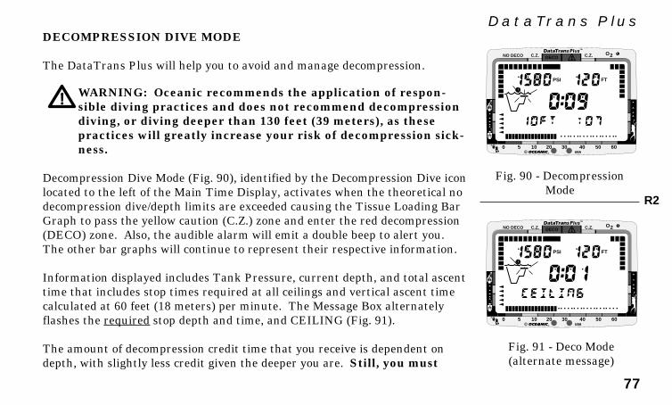
77
DataTrans PlusDECOMPRESSION DIVE MODE
The DataTrans Plus will help you to avoid and manage decompression.
WARNING: Oceanic recommends the application of respon-sible diving practices and does not recommend decompressiondiving, or diving deeper than 130 feet (39 meters), as thesepractices will greatly increase your risk of decompression sick-ness.
Decompression Dive Mode (Fig. 90), identified by the Decompression Dive iconlocated to the left of the Main Time Display, activates when the theoretical nodecompression dive/depth limits are exceeded causing the Tissue Loading BarGraph to pass the yellow caution (C.Z.) zone and enter the red decompression(DECO) zone. Also, the audible alarm will emit a double beep to alert you.The other bar graphs will continue to represent their respective information.
Information displayed includes Tank Pressure, current depth, and total ascenttime that includes stop times required at all ceilings and vertical ascent timecalculated at 60 feet (18 meters) per minute. The Message Box alternatelyflashes the required stop depth and time, and CEILING (Fig. 91).
The amount of decompression credit time that you receive is dependent ondepth, with slightly less credit given the deeper you are. Still, you must
Fig. 90 - DecompressionMode
Fig. 91 - Deco Mode(alternate message)
®
DECOC.Z. C.Z.
PSI FT
O2NO DECO
0 5 10 20 30 40 50 60
®
DECOC.Z. C.Z.
PSI FT
O2NO DECO
0 5 10 20 30 40 50 60
R2
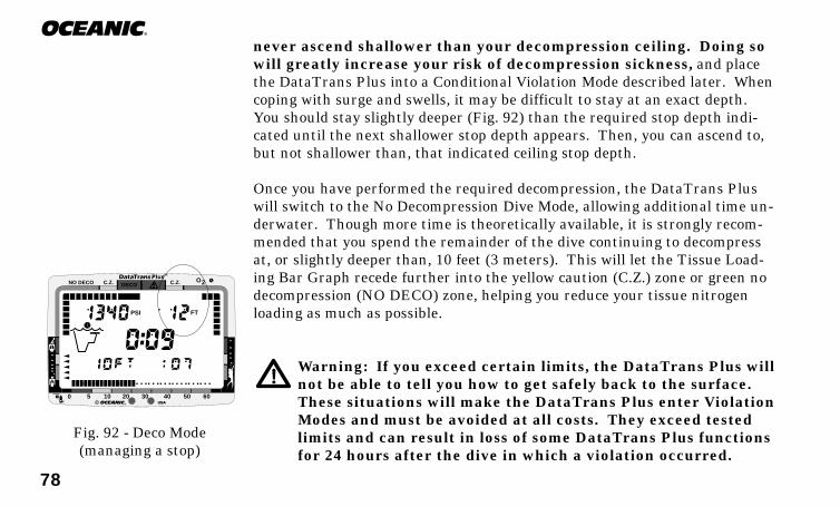
78
®
never ascend shallower than your decompression ceiling. Doing sowill greatly increase your risk of decompression sickness, and placethe DataTrans Plus into a Conditional Violation Mode described later. Whencoping with surge and swells, it may be difficult to stay at an exact depth.You should stay slightly deeper (Fig. 92) than the required stop depth indi-cated until the next shallower stop depth appears. Then, you can ascend to,but not shallower than, that indicated ceiling stop depth.
Once you have performed the required decompression, the DataTrans Pluswill switch to the No Decompression Dive Mode, allowing additional time un-derwater. Though more time is theoretically available, it is strongly recom-mended that you spend the remainder of the dive continuing to decompressat, or slightly deeper than, 10 feet (3 meters). This will let the Tissue Load-ing Bar Graph recede further into the yellow caution (C.Z.) zone or green nodecompression (NO DECO) zone, helping you reduce your tissue nitrogenloading as much as possible.
Warning: If you exceed certain limits, the DataTrans Plus willnot be able to tell you how to get safely back to the surface.These situations will make the DataTrans Plus enter ViolationModes and must be avoided at all costs. They exceed testedlimits and can result in loss of some DataTrans Plus functionsfor 24 hours after the dive in which a violation occurred.
Fig. 92 - Deco Mode(managing a stop)
®
DECOC.Z. C.Z.
PSI FT
O2NO DECO
0 5 10 20 30 40 50 60
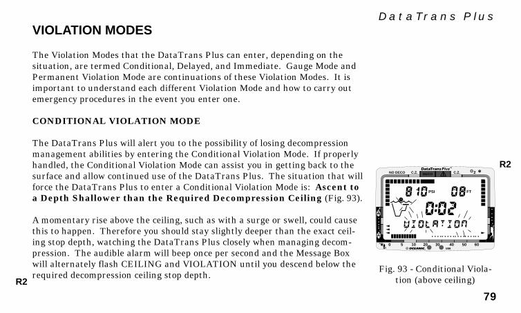
79
DataTrans Plus
®
DECOC.Z. C.Z.
PSI FT
O2NO DECO
0 5 10 20 30 40 50 60
VIOLATION MODES
The Violation Modes that the DataTrans Plus can enter, depending on thesituation, are termed Conditional, Delayed, and Immediate. Gauge Mode andPermanent Violation Mode are continuations of these Violation Modes. It isimportant to understand each different Violation Mode and how to carry outemergency procedures in the event you enter one.
CONDITIONAL VIOLATION MODE
The DataTrans Plus will alert you to the possibility of losing decompressionmanagement abilities by entering the Conditional Violation Mode. If properlyhandled, the Conditional Violation Mode can assist you in getting back to thesurface and allow continued use of the DataTrans Plus. The situation that willforce the DataTrans Plus to enter a Conditional Violation Mode is: Ascent toa Depth Shallower than the Required Decompression Ceiling (Fig. 93).
A momentary rise above the ceiling, such as with a surge or swell, could causethis to happen. Therefore you should stay slightly deeper than the exact ceil-ing stop depth, watching the DataTrans Plus closely when managing decom-pression. The audible alarm will beep once per second and the Message Boxwill alternately flash CEILING and VIOLATION until you descend below therequired decompression ceiling stop depth.
Fig. 93 - Conditional Viola-tion (above ceiling)R2
R2

80
®
®
DECOC.Z. C.Z.
PSI FT
O2NO DECO
0 5 10 20 30 40 50 60
If you descend below the required decompression ceiling before 5 minutes haveelapsed, the DataTrans Plus will continue to function as if no violation had oc-curred. In this case, no off-gassing credit will be given, and for each minuteabove the ceiling 11/2 minutes of penalty time is added to decompression stoptime.
The added penalty decompression time will have to be 'worked off' first, beforeobtaining off-gassing credit. Once the penalty time is worked-off, and off-gas-sing credit begins, required decompression stop depths and time will decreaseand the Tissue Loading Bar Graph will recede into the caution (C.Z.) zone andrevert to the No Decompression Dive Mode.
If you stay above (shallower than) the required ceiling stop depth for morethan 5 minutes, the Tissue Loading bar Graph segments will flash and the De-layed Violation Mode will be entered.
DELAYED VIOLATION MODE
Three conditions will cause the DataTrans Plus to enter the Delayed ViolationMode:
1. You remain above the required Decompression Ceiling Stop Depthfor more than 5 minutes (Fig. 94).Fig. 94 - Delayed Violation
(above ceiling >5min)
R2
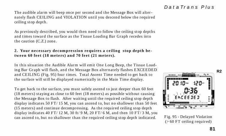
81
DataTrans Plus
®
DECOC.Z. C.Z.
PSI FT
O2NO DECO
0 5 10 20 30 40 50 60
The audible alarm will beep once per second and the Message Box will alter-nately flash CEILING and VIOLATION until you descend below the requiredceiling stop depth.
As previously described, you would then need to follow the ceiling stop depthsand times toward the surface as the Tissue Loading Bar Graph recedes intothe caution (C.Z.) zone.
2. Your necessary decompression requires a ceiling stop depth be-tween 60 feet (18 meters) and 70 feet (21 meters).
In this situation the Audible Alarm will emit One Long Beep, the Tissue Load-ing Bar Graph will flash, and the Message Box alternately flashes EXCEEDEDand CEILING (Fig. 95) four times. Total Ascent Time needed to get back tothe surface will still be displayed numerically in the Main Time display.
To get back to the surface, you must safely ascend to just deeper than 60 feet(18 meters) staying as close to 60 feet (18 meters) as possible without causingthe Message Box to flash. After waiting until the required ceiling stop depthdisplay indicates 50 FT/ 15 M, you can ascend to, but no shallower than 50 feet(15 meters) and continue decompressing. As the required ceiling stop depthdisplay indicates 40 FT/ 12 M, 30 ft/ 9 M, 20 FT/ 6 M, and then 10 FT/ 3 M, youcan ascend to, but no shallower than the required ceiling stop depth indicated. Fig. 95 - Delayed Violation
(>60 FT ceiling required)
R2

82
®
®
DECOC.Z. C.Z.
PSI FT
O2NO DECO
0 5 10 20 30 40 50 60
After Total Ascent Time reaches zero and the Tissue Loading Bar Graph re-cedes into the yellow caution (C.Z.) zone, you can surface. However, to adda greater margin of protection, Oceanic strongly recommends thatyou wait until the segments of the Tissue Loading Bar Graph are wellwithin the 'green' no decompression (NO DECO) zone, unless a lowtank pressure condition requires you to surface.
3. You descend deeper than 330 feet (99.5 meters).
NOTE: Oceanic reminds you that the DataTrans Plus is in-tended for no decompression diving at depths within 130 feet(39 meters). Expanded capabilities of the DataTrans Plus areprovided as safety features to assist you with emergency situa-tions.
Upon descending deeper than 330 feet (99.5 meters), the Tissue Loading BarGraph will flash and the Current Depth and Maximum Depth displays willonly indicate 3 dashes (Fig. 96) until ascent is made to a depth shallower than330 feet (99.5 meters), at which time the Current Depth display will be re-stored. Max Depth will continue to display 3 dashes. Exceeding the maximumoperating depth is described in detail on page 85 of this section.
Five minutes after reaching the surface from a dive in which a De-layed Violation occurred, the DataTrans Plus will enter an Immedi-ate Violation Mode and revert to Gauge Mode for 24 hours.
Fig. 96 - Delayed Violation(>330 ft / 99.5 m)
R2
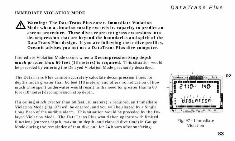
83
DataTrans Plus
®
DECOC.Z. C.Z.
PSI FT
O2NO DECO
0 5 10 20 30 40 50 60
IMMEDIATE VIOLATION MODE
Warning: The DataTrans Plus enters Immediate ViolationMode when a situation totally exceeds its capacity to predict anascent procedure. These dives represent gross excursions intodecompression that are beyond the boundaries and spirit of theDataTrans Plus design. If you are following these dive profiles,Oceanic advises you not use a DataTrans Plus dive computer.
Immediate Violation Mode occurs when a Decompression Stop depthmuch greater than 60 feet (18 meters) is required. This situation wouldbe preceded by entering the Delayed Violation Mode previously described.
The DataTrans Plus cannot accurately calculate decompression times fordepths much greater than 60 feet (18 meters) and offers no indication of howmuch time spent underwater would result in the need for greater than a 60foot (18 meter) decompression stop depth.
If a ceiling much greater than 60 feet (18 meters) is required, an ImmediateViolation Mode (Fig. 97) will be entered, and you will be alerted by a SingleLong Beep of the audible alarm. This situation would be preceded by the De-layed Violation Mode. The DataTrans Plus would then operate with limitedfunctions (current depth, maximum depth, and elapsed dive time) in GaugeMode during the remainder of that dive and for 24 hours after surfacing.
Fig. 97 - ImmediateViolation
R2
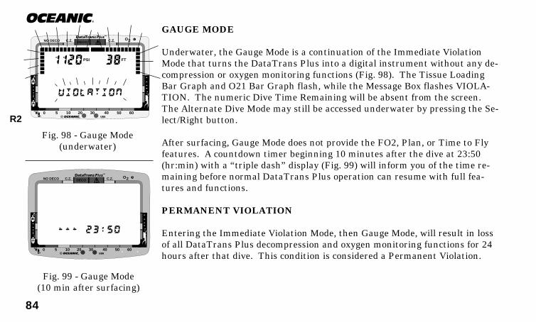
84
®
GAUGE MODE
Underwater, the Gauge Mode is a continuation of the Immediate ViolationMode that turns the DataTrans Plus into a digital instrument without any de-compression or oxygen monitoring functions (Fig. 98). The Tissue LoadingBar Graph and O21 Bar Graph flash, while the Message Box flashes VIOLA-TION. The numeric Dive Time Remaining will be absent from the screen.The Alternate Dive Mode may still be accessed underwater by pressing the Se-lect/Right button.
After surfacing, Gauge Mode does not provide the FO2, Plan, or Time to Flyfeatures. A countdown timer beginning 10 minutes after the dive at 23:50(hr:min) with a “triple dash” display (Fig. 99) will inform you of the time re-maining before normal DataTrans Plus operation can resume with full fea-tures and functions.
PERMANENT VIOLATION
Entering the Immediate Violation Mode, then Gauge Mode, will result in lossof all DataTrans Plus decompression and oxygen monitoring functions for 24hours after that dive. This condition is considered a Permanent Violation.
Fig. 98 - Gauge Mode(underwater)
®
DECOC.Z. C.Z.
PSI FT
O2NO DECO
0 5 10 20 30 40 50 60
Fig. 99 - Gauge Mode(10 min after surfacing)
R2
®
DECOC.Z. C.Z. O2NO DECO
0 5 10 20 30 40 50 60
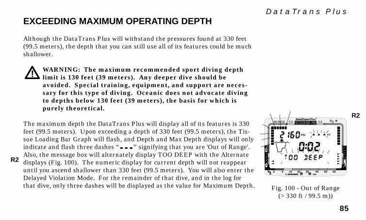
85
DataTrans Plus
®
DECOC.Z. C.Z.
PSI FT
O2NO DECO
0 5 10 20 30 40 50 60
EXCEEDING MAXIMUM OPERATING DEPTH
Although the DataTrans Plus will withstand the pressures found at 330 feet(99.5 meters), the depth that you can still use all of its features could be muchshallower.
WARNING: The maximum recommended sport diving depthlimit is 130 feet (39 meters). Any deeper dive should beavoided. Special training, equipment, and support are neces-sary for this type of diving. Oceanic does not advocate divingto depths below 130 feet (39 meters), the basis for which ispurely theoretical.
The maximum depth the DataTrans Plus will display all of its features is 330feet (99.5 meters). Upon exceeding a depth of 330 feet (99.5 meters), the Tis-sue Loading Bar Graph will flash, and Depth and Max Depth displays will onlyindicate and flash three dashes “ ” signifying that you are 'Out of Range'.Also, the message box will alternately display TOO DEEP with the Alternatedisplays (Fig. 100). The numeric display for current depth will not reappearuntil you ascend shallower than 330 feet (99.5 meters). You will also enter theDelayed Violation Mode. For the remainder of that dive, and in the log forthat dive, only three dashes will be displayed as the value for Maximum Depth. Fig. 100 - Out of Range
(>330 ft / 99.5 m))
R2
R2
86
®
OXYGEN EXPOSURE
There are few legitimate excuses for exceeding the maximum limits for expo-sure to oxygen, and the consequences of CNS (Central Nervous System) oxy-gen toxicity can be severe, resulting in Gran Mal convulsions and drowning.Diving with enriched nitrogen-oxygen (nitrox) mixtures requires special train-ing and certification.
WARNING: The oxygen features of the DataTrans Plus are in-tended for use only by recreational divers trained for nitroxdiving by an instructor certified by a recognized trainingagency to teach diving with nitrox. The DataTrans Plus is notintended for use by military or commercial divers.
By making a nitrox dive without the necessary training, preparation, andequipment, you will have placed yourself in an unnecessarily dangerous situ-ation. The DataTrans Plus is a sophisticated instrument designed with capa-bilities that go beyond the range of recreational diving with compressed air. Itshould not be considered, however, that these built-in capabilitiesprovide any implied approval or consent from Oceanic for individu-als to exceed the defined limits of oxygen exposure, as agreed on byall internationally recognized nitrox training agencies. Nitrox divingshould therefore be strictly controlled.
Be a -RESPONSIBLE DIVER
at all times.
RE
SP
ONSIBLE
DIV
ER
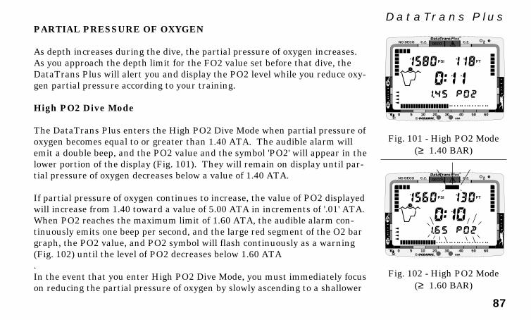
87
DataTrans PlusPARTIAL PRESSURE OF OXYGEN
As depth increases during the dive, the partial pressure of oxygen increases.As you approach the depth limit for the FO2 value set before that dive, theDataTrans Plus will alert you and display the PO2 level while you reduce oxy-gen partial pressure according to your training.
High PO2 Dive Mode
The DataTrans Plus enters the High PO2 Dive Mode when partial pressure ofoxygen becomes equal to or greater than 1.40 ATA. The audible alarm willemit a double beep, and the PO2 value and the symbol 'PO2' will appear in thelower portion of the display (Fig. 101). They will remain on display until par-tial pressure of oxygen decreases below a value of 1.40 ATA.
If partial pressure of oxygen continues to increase, the value of PO2 displayedwill increase from 1.40 toward a value of 5.00 ATA in increments of '.01' ATA.When PO2 reaches the maximum limit of 1.60 ATA, the audible alarm con-tinuously emits one beep per second, and the large red segment of the O2 bargraph, the PO2 value, and PO2 symbol will flash continuously as a warning(Fig. 102) until the level of PO2 decreases below 1.60 ATA.In the event that you enter High PO2 Dive Mode, you must immediately focuson reducing the partial pressure of oxygen by slowly ascending to a shallower
Fig. 101 - High PO2 Mode(≥ 1.40 BAR)
Fig. 102 - High PO2 Mode(≥ 1.60 BAR)
®
DECOC.Z. C.Z.
PSI FT
O2NO DECO
0 5 10 20 30 40 50 60
®
DECOC.Z. C.Z.
PSI FT
O2NO DECO
0 5 10 20 30 40 50 60
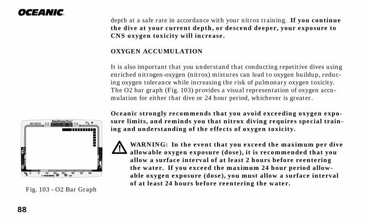
88
®
depth at a safe rate in accordance with your nitrox training. If you continuethe dive at your current depth, or descend deeper, your exposure toCNS oxygen toxicity will increase.
OXYGEN ACCUMULATION
It is also important that you understand that conducting repetitive dives usingenriched nitrogen-oxygen (nitrox) mixtures can lead to oxygen buildup, reduc-ing oxygen tolerance while increasing the risk of pulmonary oxygen toxicity.The O2 bar graph (Fig. 103) provides a visual representation of oxygen accu-mulation for either that dive or 24 hour period, whichever is greater.
Oceanic strongly recommends that you avoid exceeding oxygen expo-sure limits, and reminds you that nitrox diving requires special train-ing and understanding of the effects of oxygen toxicity.
WARNING: In the event that you exceed the maximum per diveallowable oxygen exposure (dose), it is recommended that youallow a surface interval of at least 2 hours before reenteringthe water. If you exceed the maximum 24 hour period allow-able oxygen exposure (dose), you must allow a surface intervalof at least 24 hours before reentering the water.
Fig. 103 - O2 Bar Graph
®
DECOC.Z. C.Z. O2NO DECO
0 5 10 20 30 40 50 60
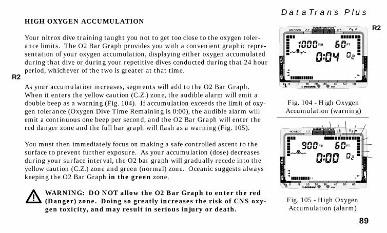
89
DataTrans Plus
®
DECOC.Z. C.Z.
PSI FT
O2NO DECO
0 5 10 20 30 40 50 60
HIGH OXYGEN ACCUMULATION
Your nitrox dive training taught you not to get too close to the oxygen toler-ance limits. The O2 Bar Graph provides you with a convenient graphic repre-sentation of your oxygen accumulation, displaying either oxygen accumulatedduring that dive or during your repetitive dives conducted during that 24 hourperiod, whichever of the two is greater at that time.
As your accumulation increases, segments will add to the O2 Bar Graph.When it enters the yellow caution (C.Z.) zone, the audible alarm will emit adouble beep as a warning (Fig. 104). If accumulation exceeds the limit of oxy-gen tolerance (Oxygen Dive Time Remaining is 0:00), the audible alarm willemit a continuous one beep per second, and the O2 Bar Graph will enter thered danger zone and the full bar graph will flash as a warning (Fig. 105).
You must then immediately focus on making a safe controlled ascent to thesurface to prevent further exposure. As your accumulation (dose) decreasesduring your surface interval, the O2 bar graph will gradually recede into theyellow caution (C.Z.) zone and green (normal) zone. Oceanic suggests alwayskeeping the O2 Bar Graph in the green zone.
WARNING: DO NOT allow the O2 Bar Graph to enter the red(Danger) zone. Doing so greatly increases the risk of CNS oxy-gen toxicity, and may result in serious injury or death.
Fig. 104 - High OxygenAccumulation (warning)
Fig. 105 - High OxygenAccumulation (alarm)
®
DECOC.Z. C.Z.
PSI FT
O2NO DECO
0 5 10 20 30 40 50 60
R2
R2

90
®
Body metabolism varies from person to person, and even from day to day. Ifyou are feeling less than 100%, or you are in less than perfect physical shape,use the caution (C.Z.) zone as a visual reference to place a wider mar-gin of protection between you and the limits of oxygen tolerance.
MESSAGE BOX WARNINGS
When diving beyond the normal limits of recreational sport diving, it is pos-sible that you will violate more than one condition at a time, such as exceedingthe maximum recommended ascent rate, ascending above a required ceilingstop depth, or exceeding the maximum allowed partial pressure of oxygen. Inthese situations, the Message Box will display the most important warning forthat time, allowing more critical warnings to override others of lesser impor-tance (Fig. 106).
UNEXPECTED LOSS OF DISPLAYED INFORMATION
While No Decompression diving, if you find that any major piece ofequipment is not functioning correctly, you must abort the dive im-mediately and surface slowly in a controlled manner. If yourDataTrans Plus stops working for any reason, it is important that you haveanticipated this possibility and are prepared for it. This is an importantreason to avoid pushing the no decompression and oxygen tolerance
Fig. 106 - Message Hierarchy
VIOLATION
GAS ALARM
EXCEEDEDCEILING
TOO FAST
TOO DEEP
91
DataTrans Pluslimits, and a critical reason to avoid entering decompression. Regard-less of your diving habits, Oceanic advises you to dive with additional backupinstrumentation that can provide the data necessary to properly surface if andwhen your primary instruments fail.
As with any other piece of equipment, unforeseen things can happen. By pre-paring ahead of time, you can spare yourself a great deal of frustration and dis-appointment. If you dive in situations where your trip would be ruinedor your safety would be jeopardized by losing the use of yourDataTrans Plus, an analog or digital backup system or use of stan-dard air (or nitrox) tables is highly recommended.
A FINAL WORD OF CAUTION
Although the DataTrans Plus represents the latest in user friendlydive computer technology, it cannot force you to understand how touse it. Before diving with the DataTrans Plus, be sure you thor-oughly understand its functions and displays. Contact your local Au-thorized Oceanic Dealer if you have a question. Above all remember,technology is not a replacement for training, experience, and com-mon sense !
Be a Responsible Diver at all times !!
RE
SP
ONSIBLE
DIV
ER
92
®
(This page intentionally left blank.)

93
DataTrans Plus
CAREand
MAINTENANCE
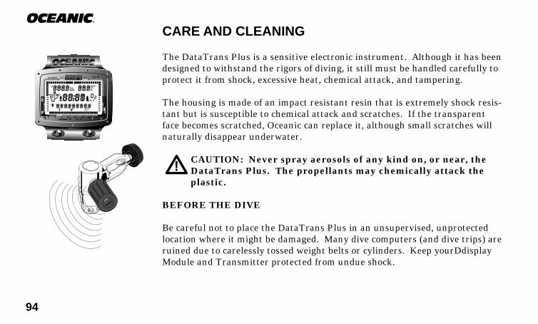
94
®
CARE AND CLEANING
The DataTrans Plus is a sensitive electronic instrument. Although it has beendesigned to withstand the rigors of diving, it still must be handled carefully toprotect it from shock, excessive heat, chemical attack, and tampering.
The housing is made of an impact resistant resin that is extremely shock resis-tant but is susceptible to chemical attack and scratches. If the transparentface becomes scratched, Oceanic can replace it, although small scratches willnaturally disappear underwater.
CAUTION: Never spray aerosols of any kind on, or near, theDataTrans Plus. The propellants may chemically attack theplastic.
BEFORE THE DIVE
Be careful not to place the DataTrans Plus in an unsupervised, unprotectedlocation where it might be damaged. Many dive computers (and dive trips) areruined due to carelessly tossed weight belts or cylinders. Keep yourDdisplayModule and Transmitter protected from undue shock.
®
DECOC.Z. C.Z.
PSIBAR M
FT
O2NO DECO
0 5 10 20 30 40 50 60
MAX
95
DataTrans PlusAFTER THE DIVE
Soak and rinse the Display Module in fresh water following each dive, andcheck the low pressure sensor guard cap to ensure that it is free of any debrisor obstructions. For the transmitter, soak and rinse the regulator in fresh wa-ter following each dive as you normally would, according to the proper mainte-nance procedures prescribed for that model. If possible, use lukewarm waterto dissolve any salt crystals. Salt deposits can also be dissolved using a slightlyacidic vinegar/water bath. After removal from a fresh water bath, place theDataTrans Plus under gently running water and towel dry before storing.Transport your DataTrans Plus cool, dry, and protected.
WARNING: Never, under any circumstances, poke any objectthrough any slots or holes of the Display Module. Doing so maydamage the depth sensor, possibly resulting in erroneous depthand/or dive time remaining displays.
ANNUAL INSPECTIONS & SERVICE
Your DataTrans Plus should be inspected annually by an Authorized OceanicDealer who will perform a factory prescribed function check and inspection fordamage or wear. To keep the 2 year limited warranty in effect, this inspectionmust be completed one year after purchase (+/- 30 days). Oceanic recom-
RE
SP
ONSIBLE
DIV
ER

96
®
mends that you continue to have this inspection performed every year to en-sure your DataTrans Plus is working properly. A convenient service record isprovided in the rear of this owner's guide. This should be signed by the servicetechnician after each annual inspection or factory service. The cost of annualinspections are not covered under the terms of the 2 year limited warranty.
WARNING: If you are in doubt about the accuracy of yourDataTrans Plus' depth readings, DO NOT attempt to dive withit until it has been inspected by Oceanic Customer Service.
It is possible to damage the DataTrans Plus depth sensor if it is not pressuretested properly. Please take heed of the following warning:
WARNING: Never pressure test the DataTrans Plus displaymodule in an air environment. Doing so may damage the depthsensor; possibly resulting in erroneous depth or time readings.
HOW TO OBTAIN SERVICE
Take your DataTrans Plus to an Authorized Oceanic Dealer.
NOTE: The transmitter and display module must be returnedtogether, regardless of the reported problem or symptom.
Responsible
97
DataTrans PlusTo return your DataTrans Plus to Oceanic:
• Remove the Transmitter from the regulator.• Package the Display Module and Transmitter together, using a cushion-
ing material to keep them isolated from each other.• Authorized Oceanic Dealers should use an Oceanic Product Return Form.• Include a legible note stating specific reason for return, your name, ad-
dress, daytime phone number, serial number, and a copy of your originalsales receipt from your Authorized Oceanic Dealer.
• Send prepaid and insured to the nearest Oceanic service facility.• If you have any questions regarding DataTrans Plus service, call Oceanic
Customer Service at (510) 562-0500, 8 to 5 PST.
NOTE: Previous dive log and history data will be erased when-ever your DataTrans Plus receives factory service.
BATTERY LIFE
The DataTrans Plus battery consumption rate varies throughout periods ofoperation, which begin upon activation and continue for 24 hours after surfac-ing from a dive. The Transmitter and Display Module consume power anytime batteries are installed in them, even in standby when pressure to theTransmitter is purged and the Display Module has shut down.
Responsible

98
®
The exact number of dives, or hours of operation, that you will obtain with aset of batteries is subject to variables such as, the number of dives conductedduring an operational period, the manufacturer, model and age of batteries ac-tually used, and the amount of time batteries remain in the Transmitter andDisplay Module during periods of inactivity.
NOTE: Tests and calculations indicate that the number ofdives that you can obtain from a set of batteries will vary. Ap-proximately 100 dives could be conducted with the recom-mended batteries. This is still considered to be substantialgiven the convenience of the user replaceable feature.
Due to the convenience of the user replaceable battery feature, Oceanic recom-mends that batteries be removed during periods of inactivity expected to ex-ceed one week and during air travel that is not conducted during repetitivedive surface intervals.
NOTE: The disposable batteries supplied with the DataTransPlus dive computer are not covered by the DataTrans Plus lim-ited 2 year warranty.
RE
SP
ONSIBLE
DIV
ER
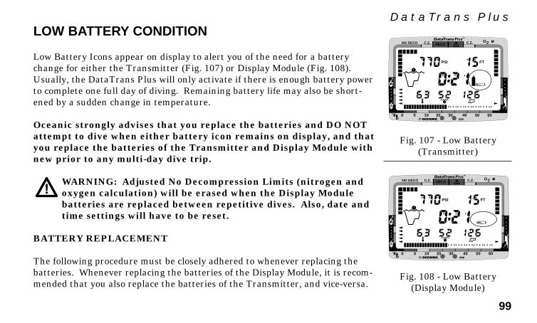
99
DataTrans Plus
®
DECOC.Z. C.Z.
PSI FT
O2NO DECO
0 5 10 20 30 40 50 60
LOW BATTERY CONDITION
Low Battery Icons appear on display to alert you of the need for a batterychange for either the Transmitter (Fig. 107) or Display Module (Fig. 108).Usually, the DataTrans Plus will only activate if there is enough battery powerto complete one full day of diving. Remaining battery life may also be short-ened by a sudden change in temperature.
Oceanic strongly advises that you replace the batteries and DO NOTattempt to dive when either battery icon remains on display, and thatyou replace the batteries of the Transmitter and Display Module withnew prior to any multi-day dive trip.
WARNING: Adjusted No Decompression Limits (nitrogen andoxygen calculation) will be erased when the Display Modulebatteries are replaced between repetitive dives. Also, date andtime settings will have to be reset.
BATTERY REPLACEMENT
The following procedure must be closely adhered to whenever replacing thebatteries. Whenever replacing the batteries of the Display Module, it is recom-mended that you also replace the batteries of the Transmitter, and vice-versa.
Fig. 107 - Low Battery(Transmitter)
Fig. 108 - Low Battery(Display Module)
®
DECOC.Z. C.Z.
PSI FT
O2NO DECO
0 5 10 20 30 40 50 60

100
®
WARNING: Damage due to improper battery replacement isnot covered by the DataTrans Plus limited 2 year warranty.Follow directions exactly.
• Apply a coin (not a screwdriver) to the recessed slot of the battery cap,and turn the cap out counterclockwise to remove it from the housing.Note: The battery compartment should only be opened in a dry and cleanenvironment, with extreme care taken to prevent the entrance of mois-ture or dust.
• Remove the battery from the cap using care not to lose the spring locatedbehind the battery. Closely examine the spring and contact area insidethe battery compartment for any signs of corrosion indicating entrance ofmoisture into the unit. If found, return your DataTrans Plus to an Au-thorized Oceanic Dealer, and DO NOT use it until it has received service.
• To remove the o-ring, press the sides with your fingertips to cause it toprotrude slightly from the groove of the cap and lift it over the head ofthe cap. DO NOT use tools to remove.
• Closely check the threads of the battery cap and the housing for any signsof damage which might impair proper threading. If found, return yourDataTrans Plus to your Authorized Oceanic Dealer, and DO NOT at-tempt to use until it has received factory service.
• To replace the o-ring, lightly lubricate it with silicon grease and stretch itslightly to work it down over the head of the cap (Fig. 109), DO NOT rollit over the threads. Ensure that it is evenly seated inside the groove
Fig. 109 - O-ringInstallation
BatteryCap
O-ring

101
DataTrans Plusabove the threads.
• Insert the spring into the cap with the large end first (small end facingout), and insert the battery into the housing (Fig. 110). For the Trans-mitter, the positive (+) end of the battery goes into the housing first withthe negative (-) end toward the cap. For the Display Module, the negative(-) end of the battery goes into the housing first with the positive (+) endtoward the cap.
• Carefully insert the battery cap into the housing and turn clockwise byhand until snug. To ensure correct threading and overcome spring pres-sure apply slight inward pressure as you begin turning the cap. Apply acoin to the recessed slot and tighten until secure.
• Activate the Display Module and watch carefully as it performs a full diag-nostic and battery check, and signal link with the Transmitter.
• Examine the LCD display to ensure it is consistently clear and sharp incontrast throughout the screen.
FLOODED BATTERY COMPARTMENT
Note: For any cause of flooding other than a bad o-ring, returnthe complete DataTrans Plus for factory service.
If moisture is found in the battery compartment, it is best to have yourDataTrans Plus inspected and cleaned by an Authorized Oceanic Dealer.
Fig. 110 - BatteryInstallation
Housing
Battery1/2AA3.6 v
( - ) ( + )
Transmitter
+
( - )( + )
Battery1/2AA3.6 v
HousingSpringBatteryCap
Display Module
-+
BatteryCap
-
Spring

102
®
To perform a repair in the field:• Remove the battery and discard, DO NOT attempt to reuse.• Check the o-ring for damage (nicks, cuts, divots, etc.). If found, discard
and replace with new.• Before replacing the o-ring and batteries, flush the battery compartment
with a solution of 50% white vinegar and 50% water. Rinse with freshwater, and allow to dry overnight or blow dry with a hair dryer (set at 'noheat') Prior to installing the spring and battery, ensure that no moistureis present around the retaining ring located inside the base of the com-partment.
Note: The retainer ring cannot be removed or replaced by theuser.
TRANSMITTER INSTALLATION INSTRUCTIONS
As an integrated unit the DataTrans Plus requires attachment of its RadioFrequency (R/F) transmitter unit to your regulator first stage.
CAUTION: Installing the Transmitter improperly to your regu-lator first stage may damage the Transmitter, regulator, orboth. Oceanic strongly recommends that installation be per-formed by an Authorized Oceanic Dealer.
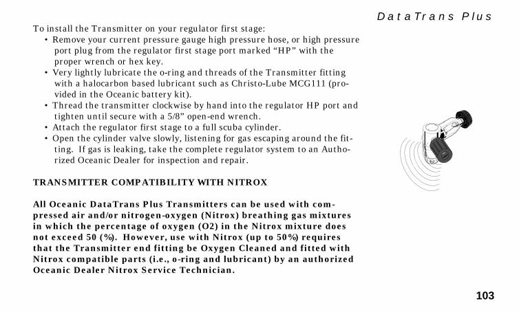
103
DataTrans PlusTo install the Transmitter on your regulator first stage:
• Remove your current pressure gauge high pressure hose, or high pressureport plug from the regulator first stage port marked “HP” with theproper wrench or hex key.
• Very lightly lubricate the o-ring and threads of the Transmitter fittingwith a halocarbon based lubricant such as Christo-Lube MCG111 (pro-vided in the Oceanic battery kit).
• Thread the transmitter clockwise by hand into the regulator HP port andtighten until secure with a 5/8” open-end wrench.
• Attach the regulator first stage to a full scuba cylinder.• Open the cylinder valve slowly, listening for gas escaping around the fit-
ting. If gas is leaking, take the complete regulator system to an Autho-rized Oceanic Dealer for inspection and repair.
TRANSMITTER COMPATIBILITY WITH NITROX
All Oceanic DataTrans Plus Transmitters can be used with com-pressed air and/or nitrogen-oxygen (Nitrox) breathing gas mixturesin which the percentage of oxygen (O2) in the Nitrox mixture doesnot exceed 50 (%). However, use with Nitrox (up to 50%) requiresthat the Transmitter end fitting be Oxygen Cleaned and fitted withNitrox compatible parts (i.e., o-ring and lubricant) by an authorizedOceanic Dealer Nitrox Service Technician.
104
®
Transmitterss that have been specifically prepared for Oxygen Ser-vice by the Oceanic factory, as identified to be Oxygen Clean andOxygen Compatible by a special tag affixed to it, can be used withany nitrogen-oxygen (Nitrox) breathing gas mixture to a maximum of100 (%) Oxygen.
If a Transmitter prepared by the Oceanic factory, and certified andtagged for Oxygen Service, is subsequently used with compressed air,it cannot then be used with nitrogen-oxygen (Nitrox) breathing gasmixtures in which the percentage of oxygen (O2) in the Nitrox will begreater than 50 (%).
Only the Oceanic factory can prepare Oceanic DataTrans Plus Trans-mitters for use with nitrogen-oxygen (Nitrox) breathing gas mixturesin which the percentage of oxygen (O2) in the Nitrox will be greaterthan 50 (%).
Responsible

105
DataTrans Plus
REFERENCE
106
®
MORE ABOUT FLYING AFTER DIVING
In 1990 the Undersea and Hyperbaric Medical Society (UHMS) published a setof guidelines aimed at minimizing the possibility of decompression sickness dueto flying too soon after diving. The UHMS suggests* divers using standard aircylinders and exhibiting no symptoms of decompression sickness wait 24 hoursafter their last dive to fly in aircraft with cabin pressures up to 8,000 feet(2,440 meters).
The two exceptions to this recommendation are:• If a diver had less than 2 hours total accumulated dive time in the last 48
hours, then a 12 hour surface interval before flying is recommended.• Following any dive that required a decompression stop, flying should be
delayed for at least 24 hours, and if possible, for 48 hours.
Since the 1990 UHMS guidelines were introduced, data from the Diver’s AlertNetwork (DAN) was introduced that resulted in DAN’s position** that “Aminimum surface interval of only 12 hours would be required in order to bereasonably assured a diver will remain symptom free upon ascent to altitude ina commercial jet airliner (altitude up to 8,000 feet/2,440 meters). Divers whoplan to make daily, multiple dives for several days, or make dives that requiredecompression stops, should take special precautions and wait for an extendedsurface interval beyond 12 hours before flight”.
* excerpted from “The UHMS Flying After Diving Workshop”
** excerpted from “DAN’s Current Position on Recreational Flying After Diving”
RE
SP
ONSIBLE
DIV
ER
107
DataTrans PlusBoth the UHMS and DAN agree that “There can never be a flying after divingrule that is guaranteed to prevent decompression sickness completely. Rather,there can be a guideline that represents the best estimate for a conservative . .. surface interval for the vast majority of divers. There will always be an occa-sional diver whose physiological makeup or special diving circumstances willresult in the bends”.
To reduce the risk of developing decompression sickness after a single no de-compression dive, current guidelines suggest waiting 12 hours prior to expo-sure to atmospheric pressures equivalent to 1,000 feet (330 meters) above sealevel, or greater. When repetitive dives are conducted during the same day, orperiod of days, it is suggested that the interval be increased to a minimum of24 hours. Note that land travel to higher elevations after diving must also beconsidered as an exposure to altitude.
MORE ABOUT ALTITUDE DIVING
WARNING: Diving at high altitude requires special knowledgeof the variations imposed upon divers, their activities, andtheir equipment by the decrease in atmospheric pressures.Oceanic recommends completion of a specialized Altitudetraining course by a recognized training agency prior to divingin high altitude lakes or rivers.
DECOMPRESSIONRULES
ARE NOT MEANTTO BE BENT
Responsible
108
®
Atmospheric pressure decreases as altitude increases above sea level. Weathersystems and ambient temperature also affect barometric pressures. Conse-quently, depth reading instruments that do not compensate for the decrease inpressure indicate depth readings shallower than the depth they are actually at.
The DataTrans Plus automatically compensates for decreased ambient pres-sure when activated at high altitudes up to 14,000 feet (4,267 meters). Its pro-gram contains a high altitude algorithm that reduces no decompression andoxygen exposure limits to add a larger zone of caution.
Whenever the DataTrans Plus is manually activated at altitudes higher than2,000 feet (610 meters), it will automatically recalibrate itself to measure depthin feet of fresh water rather than feet of sea water. Therefore, when returningto lower altitudes, diving should not be conducted until the DataTrans Plus au-tomatically clears of any residual nitrogen and oxygen loading and resets to op-erate at the new altitude.
WARNING: Altitude compensation provided by the DataTransPlus takes place when the unit is activated. DO NOT dive atany different altitude until the DataTrans Plus shuts off. It willautomatically recalibrate when reactivated at the new altitude.
RE
SP
ONSIBLE
DIV
ER

109
DataTrans PlusMORE ABOUT NITROX DIVING
WARNING: Diving with enriched nitrogen-oxygen (nitrox)mixtures requires special knowledge of the variations imposedupon divers, their activities, and their equipment by the in-creased percentage of oxygen. Oceanic recommends comple-tion of a specialized Nitrox training course by a recognizedtraining agency prior to diving with any enriched nitrogen-oxygen (nitrox) mixtures.
Both central nervous system (CNS) oxygen toxicity and pulmonary oxygentoxicity were taken into consideration when the current maximum limits (Fig.111) for exposure to oxygen were published by NOAA in the October 1991NOAA Diving Manual. Although CNS oxygen toxicity is considered the pri-mary constraint for higher levels of PO2, there are circumstances in whichpulmonary oxygen toxicity can limit exposures.
CNS oxygen toxicity is not considered likely at PO2 levels below 1.30 ATA. Itis however related to diver's work level. Performing strenuous tasks couldcause the symptoms of oxygen poisoning to occur at PO2 levels lower thanthey normally would appear during casual recreational diving.
The nitrox features of the DataTrans Plus are intended for use onlyby recreational divers trained for nitrox diving by an instructor cer-
Fig. 111 - OxygenExposure Limits
MaximumExposure Time
PO2 (ATA)
0.60 0.70 0.80 0.90 1.00 1.10 1.20 1.30 1.40 1.50 1.60
Per Dive (Min)
720 570 450 360 300 240 210 180 150 120 45
Per 24hr (Min)
720 570 450 360 300 270 240 210 180 180 150
R2
110
®
tified by a recognized training agency to teach diving with nitrox.The DataTrans Plus is not intended for use by military or commercialdivers.
WARNING: In the event that you exceed the maximum limit ofper dive allowable oxygen exposure, it is recommended that youallow a surface interval of at least 2 hours before reentering thewater. If you exceed the maximum limit of 24 hour period al-lowable oxygen exposure, you should allow a surface interval ofat least 24 hours before reentering the water.
MULTIPLE TISSUE TRACKING
The DataTrans Plus tracks twelve tissue compartments with halftimes rangingfrom 5 to 480 minutes. The Tissue Loading Bar Graph always displays thecontrolling compartment that is the only one important at that time. Think ofthe Tissue Loading Bar Graph as twelve separate transparent displays laid ontop of one another (Fig. 112). The tissue compartment that has filled up fast-est is the only one the viewer can see from the top.
At any particular point, one tissue compartment may be absorbing nitrogen,while another that was previously higher may be off-gassing. Figure 113 illus-trates the point at which one compartment “hands over” control to anothercompartment at a different depth. This feature of the Decompression Model is
RE
SP
ONSIBLE
DIV
ER

111
DataTrans Plus
Display Seen by the Diver
No. ofSegments
DECOC.Z.
NO DECO
DECOC.Z.
NO DECO
DECOC.Z.
NO DECO
DECOC.Z.
NO DECO
DECOC.Z.
NO DECO
DECOC.Z.
NO DECO
DECOC.Z.
NO DECO
15
14
13
12
11
etc.
20
80
40
120
160
etc.
TissueHalf-Time
DECOC.Z.
NO DECO
DECOC.Z.
NO DECO
DECOC.Z.
NO DECO
TissueHalf-Time
No. ofSegments
12v
12v
12^
40
20
Display Seen by the Diver
Fig. 112 - Think of the 12 tissues asoverlaid clear displays showing only themaximum bar graph reading reached
Fig. 113 - As one tissue recedes, an-other increases with the maximumreading being the only one displayed
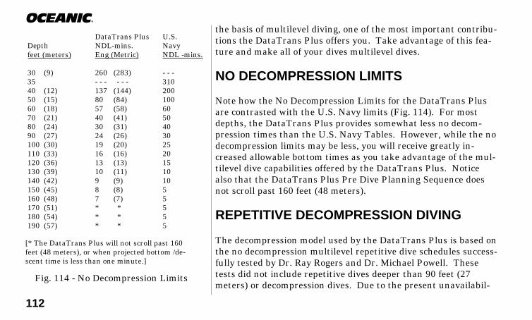
112
®
the basis of multilevel diving, one of the most important contribu-tions the DataTrans Plus offers you. Take advantage of this fea-ture and make all of your dives multilevel dives.
NO DECOMPRESSION LIMITS
Note how the No Decompression Limits for the DataTrans Plusare contrasted with the U.S. Navy limits (Fig. 114). For mostdepths, the DataTrans Plus provides somewhat less no decom-pression times than the U.S. Navy Tables. However, while the nodecompression limits may be less, you will receive greatly in-creased allowable bottom times as you take advantage of the mul-tilevel dive capabilities offered by the DataTrans Plus. Noticealso that the DataTrans Plus Pre Dive Planning Sequence doesnot scroll past 160 feet (48 meters).
REPETITIVE DECOMPRESSION DIVING
The decompression model used by the DataTrans Plus is based onthe no decompression multilevel repetitive dive schedules success-fully tested by Dr. Ray Rogers and Dr. Michael Powell. Thesetests did not include repetitive dives deeper than 90 feet (27meters) or decompression dives. Due to the present unavailabil-
DataTrans Plus U.S.Depth NDL-mins. Navyfeet (meters) Eng (Metric) NDL -mins.
30 (9) 260 (283) - - -35 - - - - - - 31040 (12) 137 (144) 20050 (15) 80 (84) 10060 (18) 57 (58) 6070 (21) 40 (41) 5080 (24) 30 (31) 4090 (27) 24 (26) 30100 (30) 19 (20) 25110 (33) 16 (16) 20120 (36) 13 (13) 15130 (39) 10 (11) 10140 (42) 9 (9) 10150 (45) 8 (8) 5160 (48) 7 (7) 5170 (51) * * 5180 (54) * * 5190 (57) * * 5
[* The DataTrans Plus will not scroll past 160feet (48 meters), or when projected bottom /de-scent time is less than one minute.]
Fig. 114 - No Decompression Limits

113
DataTrans Plusity of statistical data, DataTrans Plus decompression predictions are based onU.S. Navy theory . Therefore, pay special attention to the following warnings.
WARNING: Oceanic advocates responsible diving practices anddoes not recommend decompression diving, or diving below 130feet (39 meters). The decompression capabilities of theDataTrans Plus are intended strictly for emergency use. De-compression diving is inherently hazardous and greatly in-creases your risk of decompression sickness - even when per-formed according to the computer's calculations. In the eventthat you must make an emergency decompression dive, youmust not make another dive for at least 24 hours.
WARNING: Using the DataTrans Plus, just as using the U.S.Navy (or other) No Decompression Tables, is no guarantee ofavoiding decompression sickness, i.e. “the bends.”
CONCLUSION
The DataTrans Plus is an informational tool whose entire worth depends onunderstanding all of its features and functions, and using it correctly. Learnhow to use it and use it wisely. Have fun with the DataTrans Plus, andthank you for being a responsible diver!
Be a -RESPONSIBLE DIVER
at all times.
RE
SP
ONSIBLE
DIV
ER
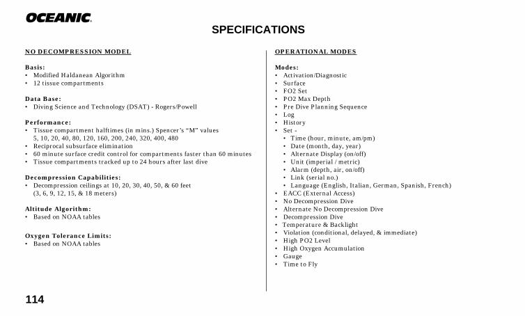
114
®
SPECIFICATIONS
NO DECOMPRESSION MODEL
Basis:• Modified Haldanean Algorithm• 12 tissue compartments
Data Base:• Diving Science and Technology (DSAT) - Rogers/Powell
Performance:• Tissue compartment halftimes (in mins.) Spencer’s “M” values
5, 10, 20, 40, 80, 120, 160, 200, 240, 320, 400, 480• Reciprocal subsurface elimination• 60 minute surface credit control for compartments faster than 60 minutes• Tissue compartments tracked up to 24 hours after last dive
Decompression Capabilities:• Decompression ceilings at 10, 20, 30, 40, 50, & 60 feet
(3, 6, 9, 12, 15, & 18 meters)
Altitude Algorithm:• Based on NOAA tables
Oxygen Tolerance Limits:• Based on NOAA tables
OPERATIONAL MODES
Modes:• Activation/Diagnostic• Surface• FO2 Set• PO2 Max Depth• Pre Dive Planning Sequence• Log• History• Set -
• Time (hour, minute, am/pm)• Date (month, day, year)• Alternate Display (on/off)• Unit (imperial / metric)• Alarm (depth, air, on/off)• Link (serial no.)• Language (English, Italian, German, Spanish, French)
• EACC (External Access)• No Decompression Dive• Alternate No Decompression Dive• Decompression Dive• Temperature & Backlight• Violation (conditional, delayed, & immediate)• High PO2 Level• High Oxygen Accumulation• Gauge• Time to Fly
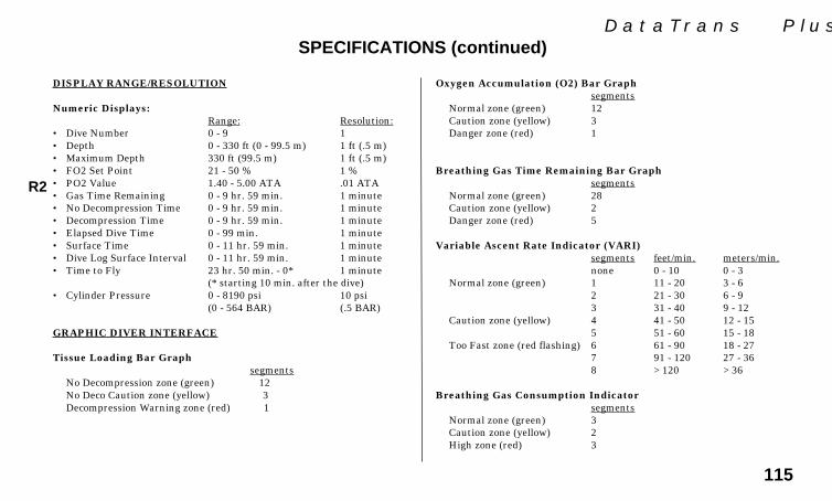
115
DataTrans PlusSPECIFICATIONS (continued)
Oxygen Accumulation (O2) Bar Graphsegments
Normal zone (green) 12Caution zone (yellow) 3Danger zone (red) 1
Breathing Gas Time Remaining Bar Graphsegments
Normal zone (green) 28Caution zone (yellow) 2Danger zone (red) 5
Variable Ascent Rate Indicator (VARI)segments feet/min. meters/min.none 0 - 10 0 - 3
Normal zone (green) 1 11 - 20 3 - 62 21 - 30 6 - 93 31 - 40 9 - 12
Caution zone (yellow) 4 41 - 50 12 - 155 51 - 60 15 - 18
Too Fast zone (red flashing) 6 61 - 90 18 - 277 91 - 120 27 - 368 >120 >36
Breathing Gas Consumption Indicatorsegments
Normal zone (green) 3Caution zone (yellow) 2High zone (red) 3
DISPLAY RANGE/RESOLUTION
Numeric Displays:Range: Resolution:
• Dive Number 0 - 9 1• Depth 0 - 330 ft (0 - 99.5 m) 1 ft (.5 m)• Maximum Depth 330 ft (99.5 m) 1 ft (.5 m)• FO2 Set Point 21 - 50 % 1 %• PO2 Value 1.40 - 5.00 ATA .01 ATA• Gas Time Remaining 0 - 9 hr. 59 min. 1 minute• No Decompression Time 0 - 9 hr. 59 min. 1 minute• Decompression Time 0 - 9 hr. 59 min. 1 minute• Elapsed Dive Time 0 - 99 min. 1 minute• Surface Time 0 - 11 hr. 59 min. 1 minute• Dive Log Surface Interval 0 - 11 hr. 59 min. 1 minute• Time to Fly 23 hr. 50 min. - 0* 1 minute
(* starting 10 min. after the dive)• Cylinder Pressure 0 - 8190 psi 10 psi
(0 - 564 BAR) (.5 BAR)
GRAPHIC DIVER INTERFACE
Tissue Loading Bar Graph segments
No Decompression zone (green) 12No Deco Caution zone (yellow) 3Decompression Warning zone (red) 1
R2

116
®
Power (Display & Transmitter)• Battery Each - 1 - 3.6 v, 1/2AA, TADIRAN® Lithium
Model TL-2150• Shelf life Up to 10 years• Replacement User replaceable (annual recommended)• Life expectancy 100 dives, or 1 year, whichever comes first
NOTE: Battery life is maximized when batteries are removed fromthe DataTrans Plus Transmitter and Display Unit during periods ofinactivity that exceed 1 week.
Activation:• Display Module - manual push button• Transmitter - gas pressure• Cannot be activated by water immersion• Cannot be activated deeper than 4 feet (1.5 m)• Cannot be activated at elevations higher than 14,000 feet (4,267 m)• Needed before first dive, and after a 12 hour surface interval.• Automatically shuts unit off if dive is made within 120 minutes after
initial activation. Reactivation required.• Cannot be shut off manually.
Special Displays Occurrence• Audible Alarm Access On demand• Diagnostic Display Activation• Out of Range >330 feet (>99.5 meters)• Gauge Mode Countdown Timer 12 – 24 hours (after violation)
OPERATIONAL PERFORMANCE
Function Accuracy• Depth ± 1% of full scale• Cylinder Pressure ± 1% of full scale• Timers 1 second per day
Dive Counter• Displays Dives #1 - #9then recycles to #1 (continues to #9)• Resets to Dive #1, upon diving (after 12 hour surface time)
Dive Log Mode• Stores 12 most recent dives in memory for viewing• After 12 dives, adds 13th dive in memory and deletes the first dive
Altitude• Operational from sea level to 14,000 feet (4,267 meters) elevation• Recalibration of depth readings from 'feet of sea water' to 'feet of fresh water'
when higher than 2,000 feet (610 meters) elevation
SPECIFICATIONS (continued)

117
DataTrans PlusRESPONSIBLE COMPUTER DIVING
Since the advent of dive computers, it is a common mistake to assume that the old traditional rules of divingno longer apply, but the truth is just the opposite. Before you dive using your DataTrans Plus, keep these ba-sic rules in mind:
• Plan each dive, and dive your plan - Your computer was not designed to make decisions for you, onlyto provide you with the information you need to make responsible decisions for yourself. This begins witha dive plan that will help you avoid a low air or decompression situation.
• Do not plan any dive that exceeds your training or experience level.• Inspect your computer before every dive - If it shows any signs of damage or abnormal function, DO
NOT dive with it until it has received factory service.• Make your deepest dive first - When making repetitive dives, it is imperative to ensure that each con-
secutive dive is shallower than the one before. This will allow your body's slower tissues to continue out-gassing nitrogen.
• Make the deepest part of your dive first, and gradually work your way to the surface using a“staircase” profile - The ability to perform multilevel diving is one of the most important contributionsof a dive computer, and you should take advantage of it. It will increase your bottom time and at thesame time decrease your risk of decompression sickness.
• Ascend slowly by following an ascent line whenever possible, or by ascending diagonally to-ward the surface - Watch the Variable Ascent Rate Iindicator closely while you ascend, and keep it inthe green zone as much as possible.
• Make a safety stop at 15-20 feet (4.5-6 m) at the end of every dive - A safety stop of as little as 5minutes has been shown to have a dramatic effect on the bubble formation in divers. It's important.Don't forget it.
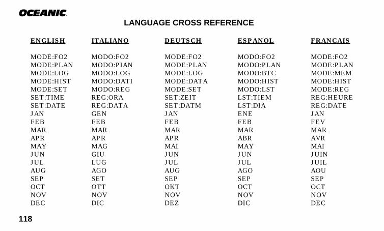
118
®
LANGUAGE CROSS REFERENCE
ENGLISH ITALIANO DEUTSCH ESPANOL FRANCAIS
MODE:FO2 MODO:FO2 MODE:FO2 MODO:FO2 MODE:FO2MODE:PLAN MODO:PIAN MODE:PLAN MODO:PLAN MODE:PLANMODE:LOG MODO:LOG MODE:LOG MODO:BTC MODE:MEMMODE:HIST MODO:DATI MODE:DATA MODO:HIST MODE:HISTMODE:SET MODO:REG MODE:SET MODO:LST MODE:REGSET:TIME REG:ORA SET:ZEIT LST:TIEM REG:HEURESET:DATE REG:DATA SET:DATM LST:DIA REG:DATEJAN GEN JAN ENE JANFEB FEB FEB FEB FEVMAR MAR MAR MAR MARAPR APR APR ABR AVRMAY MAG MAI MAY MAIJUN GIU JUN JUN JUINJUL LUG JUL JUL JUILAUG AGO AUG AGO AOUSEP SET SEP SEP SEPOCT OTT OKT OCT OCTNOV NOV NOV NOV NOVDEC DIC DEZ DIC DEC

119
DataTrans PlusLANGUAGE CROSS REFERENCE (continued)
ENGLISH ITALIANO DEUTSCH ESPANOL FRANCAIS
SET:ALT REG:ALT SET:ALT LST:ALT REG:ALTALT:ON ALT:ON ALT:AN ALT:ON ALT:OUIALT:OFF ALT:OFF ALT:AUS ALT:OFF ALT:NONSET:UNIT REG:UNIT SET:EINH LST:UNID REG:UNITUNITS UNITA' EINHEITEN UNIDADES UNITESSET:ALRM REG:ALRM SET:ALRM LST:ALRM REG:ALRMALRM:DPTH ALRM:PROF ALRM:TIEF ALRM:PRFN ALRM:PROFALRM:GAS ALRM:GAS ALRM:LUF ALRM:GAS ALRM:GASALRM:ON ALRM:ON ALRM:AN ALRM:ON ALRM:OUIALRM:OFF ALRM:OFF ALRM:AUS ALRM:OFF ALRM:NONSET:LINK REG:COLL SET:KUPP LST:CONX LIAISONSN 999999 SN 999999 SN 999999 SN 999999 NS 999999SET:LANG REG:LING SET:SPRA LST:LENG REG:LANGENGLISH ENGLISH ENGLISH ENGLISH ENGLISHITALIANO ITALIANO ITALIANO ITALIANO ITALIANODEUTSCH DEUTSCH DEUTSCH DEUTSCH DEUTSCHESPANOL ESPANOL ESPANOL ESPANOL ESPANOLFRANCAIS FRANCAIS FRANCAIS FRANCAIS FRANCAISMODE:EACC MODO:ACCE MODE:AUZU MODO:ACCE MODE:ORDIEACC 8 ACCE 8 AUZU 8 ACCE 8 ORDI 8
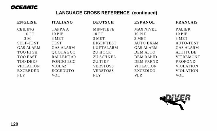
120
®
LANGUAGE CROSS REFERENCE (continued)
ENGLISH ITALIANO DEUTSCH ESPANOL FRANCAIS
CEILING TAPPA A MIN-TIEFE MAX NIVEL PALIER10 FT 10 PIE 10 FT 10 PIE 10 PIE3 M 3 MET 3 MET 3 MET 3 MET
SELF-TEST TEST EIGENTEST AUTO EXAM AUTO-TESTGAS ALARM GAS ALARM LUFTALARM GAS ALARM GAS ALARMTOO HIGH QUOTA ECC ZU HOCK DEM ALTO ALTITUDETOO FAST RALLENTAR ZU SCHNEL DEM RAPID VITREMONTTOO DEEP FONDO ECC ZU TIEF DEM PRFND PROFONDVIOLATION VIOLAZ VERSTOSS VIOLACION VIOLATIONEXCEEDED ECCEDUTO VERSTOSS EXCEDIDO VIOLATIONFLY VOL FLY VLR VOL
Responsible

121
DataTrans PlusGLOSSARY
The following are diving terms to become familiar with. Some apply specifically to the DataTrans Plus.
Air Dive - A dive conducted using air (approximately 21% oxygen & 79% nitrogen) as the breathing gas.Algorithm - A step-by-step mathematical formula designed to accomplish a particular result (i.e. Dive TimeRemaining in the DataTrans Plus).Altitude Dive - A dive made at an elevation above sea level (2,000+ ft. / 610+ m.) where a different set of nodecompression tables is used .Breathing Gas Time Remaining - A graphic display of remaining dive time based on a calculation of cylinderpressure, and the diver’s breathing rate and depth.Ascent Rate - The speed that a diver ascends toward the surface.Audible Alarm - A computer emitted tone that alerts the diver to potential danger.Breathing Gas Consumption Indicator - A graphic display of breathing gas consumption rate.C.Z. - Abbreviation for Caution Zone.Caution Zone - The yellow section of the Tissue Loading Bar Graph that gives a visual warning of a diver’sproximity to decompression.Ceiling - See decompression ceiling.Clean Dive - A dive preceded by 24 hours of no diving activity.CNS - Abbreviation for the Central Nervous System of the body.Competitive Dive - A dive conducted for profit or prize.Compartment - A term applied to the hypothetical modeling of nitrogen absorption in the tissues (more accuratethan the term “tissue” because dive computer models have no direct relation to human tissues).DCS - Abbreviation for decompression sickness, i.e., “the bends”.
R2

122
®
GLOSSARY (continued)DECO - Abbreviation for Decompression.Decompression Ceiling - The shallowest depth a diver may reach upon ascent without risking decompressionsickness.Decompression Stop - The depth(s) at which a diver must pause during ascent to allow absorbed nitrogen toescape naturally from the tissues.Depth Sensor - an electro-mechanical device that converts water pressure into an electrical signal, that isconverted to a visual depth display.Diagnostic Mode - The first display seen on dive computers after initial activation during which time a self–checkfor internal faults is performed.Display - A visual readout of information.Dive Log Mode - A computer display of previous dive information.Dive Time Remaining - A display of the time before a diver must surface based on no-decompression status,oxygen accumulation status, or tank pressure.Elapsed Dive Time - The total time spent underwater during a dive between 5 feet (1.5 meters) on initialdescent to 3 feet (1 meter) on final ascent.FO2 - The fraction (percent / 100) of oxygen (O2) in the breathing gas mixture.Graphic Diver Interface™ - A feature of Oceanic dive computers. Easily understandable color coded bar graphsthat indicate diver status; green = normal, yellow = caution, red = danger.Icon - a small pictorial representation of an operational modeIntegrated Dive Computer - A dive computer that monitors and displays cylinder pressure in addition to nodecompression information.LCD - Abbreviation for liquid crystal display, an easily viewed low voltage display usually found on dive computers

123
DataTrans PlusGLOSSARY (continued)
Maximum Depth - The deepest depth attained during a dive.Message Box - An alpha/numeric display which provides various warnings and messages to the diver to betterclarify on-screen information and audible alarm signals.Mode - A specific set of functions in a dive computer.Modular Dive Computer - A dive computer that is not physically connected to the diver’s air supply.Multiplexing Display - A display on an instrument that alternates to show different information relating toseparate events.Multi-level Dive - A type of dive profile where the diver spends various times at different depths (opposite of a“Square Wave” dive profile).Nitrox - A nitrogen-oxygen breathing gas mixture that contains a higher fraction of oxygen than air.Nitrox Dive - A dive conducted using nitrox (22 to 50 % O2) as the breathing gas.No Deco - Abbreviation for No Decompression.No Deco Time Remaining - The amount of dive time remaining based on no-decompression status.No Decompression - Any part of a dive where the diver can surface without requiring a decompression stop.O2 Bar Graph - A visual representation of oxygen accumlation on a dive computer display.Oceanglo™ - An Oceanic name for an instrument backlight feature.OceanLink™ - An Oceanic name for a for a PC interface hardware/software package.OTU - Abbreviation for oxygen tolerance unit. A Hamilton's Repex method term for oxygen dose.Out of Range - The point at which a dive computer can no longer supply correct dive information.Oxygen Tolerance - Dose or exposure to the physiological affects of elevated levels of oxygen.Oxygen Toxicity - The adverse physiological affects of exposure to elevated levels of oxygen.Partial Pressure - The proportion of the total pressure contributed by a single gas in a mixture of gases.
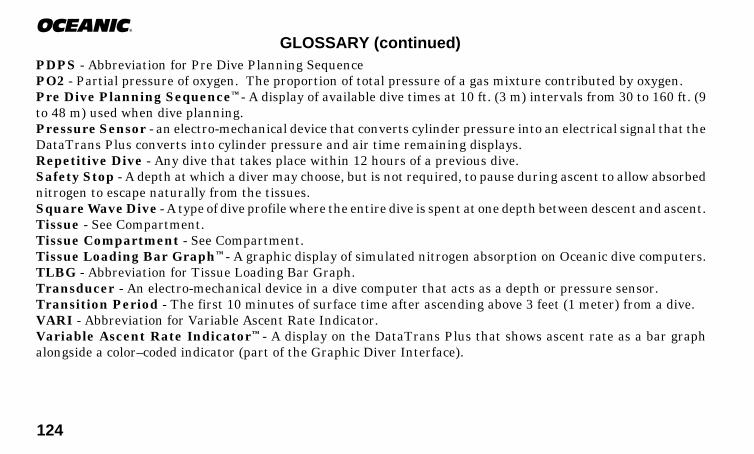
124
®
GLOSSARY (continued)PDPS - Abbreviation for Pre Dive Planning SequencePO2 - Partial pressure of oxygen. The proportion of total pressure of a gas mixture contributed by oxygen.Pre Dive Planning Sequence™ - A display of available dive times at 10 ft. (3 m) intervals from 30 to 160 ft. (9to 48 m) used when dive planning.Pressure Sensor - an electro-mechanical device that converts cylinder pressure into an electrical signal that theDataTrans Plus converts into cylinder pressure and air time remaining displays.Repetitive Dive - Any dive that takes place within 12 hours of a previous dive.Safety Stop - A depth at which a diver may choose, but is not required, to pause during ascent to allow absorbednitrogen to escape naturally from the tissues.Square Wave Dive - A type of dive profile where the entire dive is spent at one depth between descent and ascent.Tissue - See Compartment.Tissue Compartment - See Compartment.Tissue Loading Bar Graph™ - A graphic display of simulated nitrogen absorption on Oceanic dive computers.TLBG - Abbreviation for Tissue Loading Bar Graph.Transducer - An electro-mechanical device in a dive computer that acts as a depth or pressure sensor.Transition Period - The first 10 minutes of surface time after ascending above 3 feet (1 meter) from a dive.VARI - Abbreviation for Variable Ascent Rate Indicator.Variable Ascent Rate Indicator™ - A display on the DataTrans Plus that shows ascent rate as a bar graphalongside a color–coded indicator (part of the Graphic Diver Interface).

125
DataTrans PlusACCESSORIES
The following optional items are available from your Authorized Oceanic Dealer:
• P/N 04.6175 Battery Kit - includes 2 batteries, 2 o-rings (smaller for Display Module, larger for Transmitter), silicon grease.
• P/N 04.6175.10 Battery Kit (Transmitter only) -includes 1 battery, o-ring, silicon grease
• P/N 04.6175.20 Battery Kit (Display Module only) -includes 1 battery, o-ring, silicon grease
• P/N 04.8100 Lens Protector - adheres to the Display Module lens, prevents scratches
• P/N 04.4200 Transit Clip - retractable mounting device for attaching Display Module to D-ring
• P/N 04.1600 Compass Attachment Kit - for attaching an Analog Compass installed in a Hose MountBoot to a DataTrans Plus fitted with a Transit Clip
• P/N 04.1700 Compass Attachment Kit - for attaching a Digital Compass installed in a Hose MountBoot to a DataTrans Plus fitted with a Transit Clip
• P/N 04.4870 OceanLog™for DataTrans Plus - PC Download Package (hardware & software)
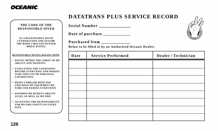
126
®
DATATRANS PLUS SERVICE RECORD
Serial Number ________________
Date of purchase ______________
Purchased from _______________Below to be filled in by an Authorized Oceanic Dealer:
RE
SP
ONSIBLE
DIV
ER
Date Service Performed Dealer / Technician
THE CODE OF THERESPONSIBLE DIVER
AS A RESPONSIBLE DIVERI UNDERSTAND AND ASSUME
THE RISKS I MAY ENCOUNTERWHILE DIVING.
RESPONSIBLE DIVING BEGINS WITH
• DIVING WITHIN THE LIMITS OF MY ABILITY AND TRAINING
• EVALUATING THE CONDITIONS BEFORE EVERY DIVE AND MAKING SURE THEY FIT MY PERSONAL CAPABILITIES
• BEING FAMILIAR WITH AND CHECKING MY EQUIPMENT BE- FORE AND DURING EVERY DIVE
• KNOWING MY BUDDY'S ABILITY LEVEL AS WELL AS MY OWN
• ACCEPTING THE RESPONSIBILITY FOR MY OWN SAFETY ON EVERY DIVE


Doc. No. 12-2022,R3 (4/99)© 2002 Design 1997


![VEET60 R02- 04feb2010 150dpi[1]](https://img.dokumen.tips/doc/110x75/5571fd55497959916998da72/veet60-r02-04feb2010-150dpi1.jpg)


