Embed Size (px)
Citation preview

The vital link in the interconnected car
Complete range of solutions for all automotive networking standards

2 The vital link in the interconnected car
Our technologies play a vital role in making connected in-car systems a reality. Using proven protocols we’ve created comprehensive IVN solutions for systems controlling aspects such as traction, ABS, lighting, windows, mirrors and ride comfort. Extensive system research and development at our Automotive Innovation Center (AIC) in Hamburg has given NXP the experience to provide you with leading-edge CAN,
LIN & FlexRay solutions, with exceptional EMC performance, low power consumption and system fail-safe features to meet today’s and tomorrow’s network requirements. And as you would expect, all these solutions meet the stringent automotive quality and service requirements, clearly demonstrated by the shipment in 2005 of our 1 billionth IVN transceiver.
Connecting fl exible intelligence in the car
Meeting the comfort, convenience, safety and security demands of
automotive consumers, as well as increasing driving pleasure and
minimizing environmental impact, continues to extend the scope
of in-car electronic systems. One of the key enabling technologies
behind this trend is In-Vehicle Networking (IVN) and, acknowledged by
the industry as the leading innovator in this area, NXP Semiconductors
provides proven solutions that set the standard.

The vital link in the interconnected car
And with NXP as a long-term IVN development partner, you are assured of early access to emerging technologies for steer-by-wire, brake-by-wire and Safe-by-Wire Plus. Through close working relationships with major automotive customers and core membership of key industry consortia, such as FlexRay and Safe-by-Wire Plus, we are driving forward future automotive system solutions. Together we can transform today’s car into the intelligent personal transport system of tomorrow.

4 The vital link in the interconnected car
NXP continues to develop products that are not only compatible with today’s
systems, but offer designers the fl exibility to incorporate the technology of
tomorrow, bringing cutting-edge systems to market fi rst. Our CAN/LIN-bus and
advanced SOI silicon process developments have ensured our leading position
in automotive IVN progress. We have improved temperature capabilities
(up to 175ºC) and our involvement in key industry consortia keeps us one step
ahead of the competition, bringing you the benefi ts of the latest developments.

5The vital link in the interconnected car
CANEffectively the standard for powertrain and body electronics networks, CAN-based IVNs are the fi rst step on the path to embedding intelligence throughout the car. From the introduction of the PCA82C250 more than a decade ago, our single-wire, high-speed and fault-tolerant CAN solutions continue to ensure the highest levels of data integrity and system performance. As the leading CAN innovator, our comprehensive family of devices continues to evolve to include capabilities such as low power consumption. And among the many new developments is a family of Fail-Safe System Basis Chips (SBCs), which increase integration, reduce cost, simplify design-in and offer a comprehensive set of fail-safe features. These SBCs will help meet the changing needs of the automotive industry, such as the increased use of permanently powered nodes even under ‘ignition-off’ conditions.
LINImproving both the cost-effectiveness and fl exibility of in-vehicle networking, LIN (Local Interconnect Network) can be used to connect various nodes in a localized area, for example the door lock, mirror and window lift in the doors. As an Associate Member of the LIN consortium, NXP has given momentum to the introduction of this latest standard for in-vehicle sub-networks and is driving the defi nition of the LIN physical layer. We’re already
building on our LIN capabilities to bring you extended functionality and further reduce system cost through dedicated LIN SBCs and a LIN-slave-node product.
FlexRayAs the number of sensors, actuators and control systems for safety, reliability and comfort systems within vehicles increases, a time-triggered, high data-rate communication system is essential. Drawing on our heritage as a core founding member of the FlexRay industry consortium, which is developing the communications protocol and physical layer that will form the core of all critical in-car control applications. Drawing on our extensive IVN knowledge, NXP Semiconductors will serve this emerging market, giving our customers early access to dedicated FlexRay transceiver and microcontroller chipsets.
Safe-by-Wire PlusDriver and passenger safety have always been critical automotive concerns, and manufacturers are already incorporating more and more safety features across their model ranges. NXP is working to develop a rapid and reliable communication system to ensure the right safety function is activated at the right time. This system will simplify passenger restraint system design, allowing rapid customization and reduced costs, so that the highest level of protection is available in all vehicles.
Driving standards

6 The vital link in the interconnected car
FlexRay4 TJA1080: Node and Star Transceiver4 TJA1082: Basic Node Transceiver
CANSingle-Wire CAN:4 AU5790
High Speed CAN:4 PCA82C250: (with standby)4 PCA82C251: (with standby)4 TJA1050: (no standby)4 TJA1040: (with standby)4 TJA1041: (with standby and sleep)4 TJA1041A: (with standby and sleep)4 UJA1065: HS-CAN/LIN Fail-Safe System Basis Chip4 UJA1066: HS-CAN Fail-Safe System Basis Chip
Fault Tolerant CAN:4 TJA1054: (with standby and sleep)4 TJA1054A: (with standby and sleep)4 TJA1055: (with standby and sleep)4 TJA1055/3 (with standby and sleep)4 UJA1061: FT-CAN/LIN Fail-Safe System Basis Chip
32-bit ARM-based Gateway Controllers4 SJA2010 CAN/LIN4 SJA2020 CAN/LIN4 SJA2510 CAN/LIN/FlexRay
IVN overview

The vital link in the interconnected car
LIN4 TJA1020: Stand-alone LIN Transceiver4 TJA1021: Stand-alone LIN Transceiver4 UJA1061: FT-CAN/LIN Fail-Safe System Basis Chip4 UJA1065: HS-CAN/LIN Fail-Safe System Basis Chip4 UJA1023: LIN I/O slave4 UJA1069: LIN Slave Fail-Safe System Basis Chip
Safe-by-Wire Plus4 UJA6402: Dual channel master4 UJA6203: Raw data slave

8 The vital link in the interconnected car
Advancing silicon for automotive processes

9The vital link in the interconnected car
NXP’s SOI (Silicon-on-Insulator) technology is the foundation for the outstanding
performance of our IVN solutions. Developed specifi cally to integrate different
device types - power, analog and digital - on a single die, our A-BCD (Advanced
Bipolar-CMOS-DMOS) family of fabrication processes brings crucial protection to
sensitive electronics, low power and superior EMC performance. This effectively
eradicates potentially perilous miscommunication in the electrically noisy and
hazardous automotive environment.
Advancing silicon for automotive processes

10 The vital link in the interconnected car
As the networks within a car increase in complexity, an intelligent system for in-car connectivity is essential. In response to the increasing computation and memory demands that in-car networks and standards such as FlexRay are making, the market is moving towards digital IVN technologies. In parallel with developments extending existing protocols and systems, NXP designs dedicated digital IVN solutions, leading to faster and more reliable networks, with decentralized intelligence.
With such increasingly complex in-vehicle networks, new and improved gateways, bridges, fi rewalls and dedicated data link controllers are required to serve the various sub-networks. NXP has close relationships with leading car manufacturers and is working towards incorporating these functions in production cars over the next few years. With our already impressive product range and vast experience and expertise, you cannot fi nd a better partner than NXP to develop the automotive networking solutions of the future.
Building on a leading position
The future of automotive solutions is full of exciting and challenging prospects. Imagine a car that can drive itself and can recognize and adapt to the person behind the wheel. Then picture the driving revolution that would follow such a development - with reduced journey times due to congestion-free traffi c systems, greatly improved driver and passenger safety, and pure ease and comfort of driving. This vision may be far-sighted, but the developments taking place today are forming the foundations for future systems to make this a reality.

11The vital link in the interconnected car

www.nxp.com
NXP Semiconductors is in the process of being established as a separate legal entity in
various countries worldwide. This process will be fi nalized in the course of 2006.
© 2006 Koninklijke Philips Electronics N.V.
All rights reserved. Reproduction in whole or in part is prohibited without the prior written
consent of the copyright owner. The information presented in this document does not
form part of any quotation or contract, is believed to be accurate and reliable and may be
changed without notice. No liability will be accepted by the publisher for any consequence
of its use. Publication thereof does not convey nor imply any license under patent- or other
industrial or intellectual property rights.
Date of release: September 2006
Document order number: 9397 750 15741
Printed in the Netherlands

A complete CAN family from transceivers to gateways
Key featuresÑ CAN is a robust protocol – essential for automotive
applicationsÑ ISO 11898 and SAE/J2411 are open standards - Well documented and fully supported worldwideÑ Choice of three CAN physical layer options - High-speed (HS) for high data rates - Fault-tolerant (FT) for additional robustness - Single-wire (SW) for minimum wiring
NXP CAN portfolioÑ Vast experience with CAN in automotive applications - Over one billion transceivers shipped in September 2005Ñ Range of transceivers and protocol controllers for all three
CAN physical layer implementations Ñ A family of innovative products - Offer additional fail-safe and low-power features - Golden devices for new CAN standards - Best-in-class EMC performance using versatile
SOI technology
Ñ Further integration simplifi es individual node and system design
- Gateway controllers integrating multiple CAN controllers with a 32-bit ARM processor
- Fail-Safe System Basis Chips (SBCs) combining transceivers and voltage regulators with an autonomous node Fail-Safe system
The Controller Area Network (CAN) bus is the primary automotive networking protocol for powertrain, backbone bus and body electronics. NXP has been recognized as the leading CAN innovator ever since our fi rst industry-standard PCA82C250 transceiver set the benchmark for high-speed CAN. We now offer designers a comprehensive portfolio comprising automotive-grade transceivers for all CAN physical layer options (high-speed, fault-tolerant and single-wire), stand-alone protocol controllers, System Basis Chips and the latest in IVN gateway ICs, delivering the performance and functionality needed for today’s wide variety of in-vehicle networking applications.
NXP Semiconductors has played a leading role in establishing CAN as the automotive networking standard. Covering all CAN physical layer options, our product portfolio includes automotive-grade high-speed, single-wire and fault-tolerant transceivers along with stand-alone protocol controllers and Fail-Safe System Basis Chips. And all our next-generation devices use the fl exible SOI technology for best-in-class EMC performance.
Add value to your networks with CAN solutions that set the standard

As the initial choice of CAN physical layer depends mostly on the network performance required, our CAN solutions ensure your selection meets the highest standards possible. Of the three current implementations of the CAN physical layer, high-speed CAN offers the highest transmission speed (up to 1 Mbits/s). Fault-tolerant CAN operates at a slower rate (125 kbits/s) but maintains functionality in the case of a broken or shorted bus wire – particularly important in body electronics where the wiring harness is more vulnerable. Both of these CAN physical layer implementations interconnect network nodes via a two-wire twisted pair bus with end-termination. Single-wire CAN is used primarily to reduce wiring in body electronics implementations and for diagnostic purposes, and operates up to 41.6 kbits/s.
Delivering value-added performance to automotive CAN networksThe CAN protocol assumes good connections and interference-free signals between nodes in a network. As the CAN protocol itself is not application specific, the automotive environment presents a significant challenge to achieving accurate operation. Obvious risks include physical damage or disturbance and electromagnetic interference. Another important factor is the battery power source, which puts additional demands on power consumption and short-circuit protection. The ISO and SAE CAN standards do not cover all these eventualities, leaving scope for extra functionality and reliability improvements when implementing CAN networks.
All NXP CAN transceiver and controller devices deliver more than the minimum CAN standard requirements, such as comprehensive fail-safe features, diagnostics and low-power modes. Many of these additional features are then actually adopted by newer versions of the standards, another process in which our leading role continues. We were also first to introduce automotive-grade transceivers to the market.
Failure management in an automotive CAN network serves one goal: keeping the car going. When a failure is detected, the robust CAN protocol handles bus arbitration and the re-transmission of messages, helping minimize effects on the rest of the network and the car. Supplementing the error handling capabilities of the CAN protocol and the selected physical layer, NXP transceivers all provide additional protective functionality to help safeguard against hardware failures.
Power saving is important for key-off functionality, with networks remaining in standby when the car’s engine is switched off. These systems are directly connected to the battery, so power consumption must be kept low. Also, in partial networks (where some nodes remain active when the rest of the network is switched off) the key-on transceivers have to leave the active part of the network unaffected when
their power supply is cut. Once again, this is an area where our CAN family delivers the added-value features required by today’s automotive applications.
The CAN protocol
In networked applications the generic ISO/OSI reference model (illustrated) identifies seven distinct communication layers, excluding the actual bus wiring. What is commonly referred to as CAN involves only two of these layers – the data link layer and the physical layer – and is covered by the ISO 11898 standard. In CAN applications the higher-level layers of the ISO/OSI model deal with the application-specific processing of the CAN messages. As the actual CAN standard only addresses the basic network communications, this leaves the implementation of features such as fail-safe behaviour and low-power modes as proprietary options.
The ISO 11898 standard is divided into three sections: ISO 11898-1 covers the CAN protocol, while parts -2 and -3 handle two of the three standardized implementations of the CAN physical layer (HS-CAN and FT-CAN respectively). Although the transmission medium is not included in the standard, ISO does assume CAN_L and CAN_H bus connections and defines the electrical signal levels for them.
Single-wire CAN is the third standardized CAN physical layer implementation in use today and is covered under the SAE/J2411 standard. SW-CAN uses only the CAN_H connection, taking the node’s ground as reference level. To maintain low electromagnetic emission, the maximum communication speed of SW-CAN systems is limited.
Layer diagram of ISO/OSI reference model
Application Layer
Presentation Layer
Session Layer
Transport Layer
Network Layer
Data Link Layer
Physical Layer
5
Logical Link Control
Medium Access Control
Physical Signalling
Physical Medium Attachment
Medium Dependant Interface
Higher LayerProtocols
CAN ProtocolController
CANTransceiver
Transmission MediumBus
Wiring
7
6
4
3
2
1

Roof:Rain SensorLight Sensor/ControlSun Roof
Seat:Seat Position MotorsOccupancy Sensor Control Panel
Door:Mirror Motor/SwitchWindow LifterSeat Control SwitchesDoor Lock
Climate:Small MotorsControl Panel
Steering Wheel:Wiper Switch
Light SwitchesCruise Control
Body & Comfort:Positioning MotorsSensorsBackbone Bus
Engine Management:Fuel Injection
GearboxEngine DiagnosticsExhaust Emissions
Regulation
Chassis Control:ABS
Traction ControlElectronic Stability Program
Overview of CAN physical layer characteristics and application areas
Features HS-CAN FT-CAN SW-CAN
Data link layer standard ISO 11898-1 ISO 11898-1 ISO 11898-1
Physical layer standard ISO 11898-2 ISO 11898-3 SAE/J2411
Number of bus wires 2 (twisted pair) 2 (twisted pair) 1
Maximum bus speed 1 Mbits/s 125 kbits/s 33/41.6 kbits/s
Bus communication signal
Bus termination principle
Bus wire short-circuit and
interrupt tolerance
limited short-circuit tolerance tolerant against any single bus
wire short or interrupt
no tolerance
NXP transceiver
features 1
- bus dominant time-out
- bus clamping protection
- partial networking support
- stand-by and sleep modes
- node power management
- local and remote wake-up
- failure diagnosis
- bus dominant time-out
- bus clamping protection
- partial networking support
- stand-by and sleep modes
- node power management
- local and remote wake-up
- failure diagnosis
- loss of ground protection
- 100 kbits/s flash mode
- partial networking support
- selective sleep
Automotive applications - engine management
- backbone bus
- body & comfort
- body & comfort - body & comfort
1 depending on the transceiver used
FT-CAN FT-CAN FT-CAN
5V -
4V -
2.5V -
1V -
0V -recessive recessivedominant
t
HS-CAN HS-CAN HS-CAN
5V -
4V -
2.5V -
1V -
0V -recessive recessivedominant
t
SW-CAN SW-CAN SW-CAN
5V -
4V -
2.5V -
1V -
0V -recessive recessivedominant
t

www.nxp.com
© 2006 Koninklijke Philips Electronics N.V.
All rights reserved. Reproduction in whole or in part is prohibited without the prior written consent of the copyright owner. The
information presented in this document does not form part of any quotation or contract, is believed to be accurate and reliable
and may be changed without notice. No liability will be accepted by the publisher for any consequence of its use. Publication
thereof does not convey nor imply any license under patent- or other industrial or intellectual property rights.
Date of release: September 2006
Document order number: 9397 750 15742
Printed in the Netherlands
NXP Semiconductors is in the process of being established as a separate legal entity in various countries worldwide. This process will be finalized in the course of 2006.
NXP delivers proven CAN solutions that set the standard. As CAN develops further in the car, we enable manufacturers to bring even higher performance to their CAN applications with drop-in upgrades of existing devices as well as innovative new products. The table gives an overview of our CAN product portfolio - further details can be found on separate leaflets.
The transceiver family for all CAN physical layersThe PCA82C250 transceiver became the industry standard for high-speed CAN applications and firmly established NXP as the leading CAN innovator. As CAN developed, we continued to lead with drop-in upgrades of existing high-speed, fault-tolerant and single-wire devices. Fabricated using our unique SOI technology, all our latest CAN transceivers offer best-in-class EMI and EME performance and comply fully with ISO and SAE standards, managing proper signal levels and message filtering. In addition, low reverse currents mean unpowered nodes do not disturb networks, while comprehensive fail-safe features help safeguard operation.
Fail-Safe System Basis Chips – effortless solutions to complex challengesAs more and more systems in cars are network based, the complexity of in-vehicle networks increases. Designing a reliable system becomes an escalating challenge, especially where network nodes are permanently connected to the battery. One effective way to reduce this design effort is through smart integration of common ECU functionality and fail-safe features. Highly integrated, our Fail-Safe System Basis Chips achieve exactly that.
By combining transceivers, voltage regulators, programmable window watchdog and a fully embedded fail-safe system on
a single chip, Fail-Safe SBCs greatly simplify design effort and FMEA for ECUs and networks. The autonomous fail-safe system offers excellent protection against network lock-ups and dead batteries. And the uniform Fail-Safe SBC family also makes it very easy to exchange physical layers on ECUs, with maximum re-use of ECU hardware and software.
Managing networks with dedicated protocol and gateway controllersSupporting our CAN transceiver family, our stand-alone CAN protocol controllers can be used within both automotive and general industrial environments. The successor of the PCA82C200, the SJA1000 implements the enhanced PeliCAN operation mode, which fully supports the CAN 2.0B protocol specification.
With the industry trend to further integrate system functions, we also offer automotive-grade 32-bit ARM-based microcontrollers with embedded CAN protocol controllers. These devices are tailored to the specific demands of vehicle dynamics as well as body and safety applications.
NXP CAN product portfolio
Products HS-CAN FT-CAN SW-CAN
CAN protocol controllers SJA1000
SJA2020 1
SJA1000
SJA2020 1
SJA1000
SJA2020 1
CAN transceivers PCA82C250
PCA82C251
TJA1050
TJA1040
TJA1041
TJA1041A
TJA1054
TJA1054A
TJA1055
TJA1055/3
AU5790
Fail-Safe System Basis
Chips 2
UJA1065 3
UJA1066
UJA1061 3
1 IVN gateway controller with 32-bit ARM7 µC, 6 CAN protocol controllers and 4 LIN protocol controllers
2 CAN transceiver, 2 voltage regulators, programmable window watchdog and fully embedded fail-safe system
3 Also includes a LIN transceiver

High-speed CAN transceivers TJA104x, TJA1050 and PCA82C25x
HS-CAN transceiver portfolioÑ PCA82C250 and PCA82C251 - The most widely used HS-CAN transceivers in the worldÑ TJA1050 - Ideal for nodes not requiring a low-power mode - Vastly improved EMC and power-off behaviorÑ TJA1040 - The best choice transceiver for key-on nodes in partial networks - Very low standby current (10 µA with wake-up via the bus)Ñ TJA1041 and TJA1041A - The best choice transceivers for continuously powered nodes - Very low sleep mode current (20 µA for the whole node)
Key featuresÑ All NXP HS-CAN transceivers are fully ISO 11898-2 compliant - Qualifi ed for automotive applications - Meet ISO standard over the full voltage and
temperature rangeÑ NXP transceivers offer additional features to support the
specifi c needs of automotive HS-CAN applications - Fail-safe features and power saving modes help contain
network failures and reduce power consumptionÑ NXP HS-CAN transceivers are found in every type of
automotive HS-CAN network in use today
At fi rst only used for engine management networks, High-speed CAN is now commonly used throughout the car, including body and comfort and backbone applications. Addressing the specifi c requirements of larger and more complicated automotive CAN networks through continuous innovation, functionality such as failure management and low-power modes are now a key component of our HS-CAN transceiver family.
Following on from the PCA82C250 NXP offers a choice of stand-alone transceivers fully pin-compatible with their predecessor, that address the additional needs of today’s HS-CAN automotive networks. Each provides a combination of power modes and protective features to suit specifi c applications and network topologies throughout the car. And with our unique SOI process, EMC performance is greatly improved – in some designs completely eliminating the need for choke suppresser coils.
As the leading supplier of CAN solutions, NXP continues to raise the performance level of this popular in-vehicle networking standard. Our HS-CAN transceiver portfolio addresses a variety of application and network topologies. With advanced functionality such as failure management and power saving, our drop-in upgrades and innovative new products deliver the performance needed by all high-speed CAN applications.
The simplest path to enhanced CAN functionality and performance

www.nxp.com
© 2006 Koninklijke Philips Electronics N.V.
All rights reserved. Reproduction in whole or in part is prohibited without the prior written consent of the copyright owner. The
information presented in this document does not form part of any quotation or contract, is believed to be accurate and reliable
and may be changed without notice. No liability will be accepted by the publisher for any consequence of its use. Publication
thereof does not convey nor imply any license under patent- or other industrial or intellectual property rights.
Date of release: September 2006
Document order number: 9397 750 15744
Printed in the Netherlands
NXP Semiconductors is in the process of being established as a separate legal entity in various countries worldwide. This process will be finalized in the course of 2006.
TJA1041/1041A – flagship solutionsOur most advanced stand-alone HS-CAN transceivers, both the TJA1041 and TJA1041A feature a sleep mode with inhibit output in addition to a standby mode, providing power supply control for the entire node. This results in a node with extremely low standby current, yet is still capable of waking up via the bus. An extended feature set includes fail-safe features, network diagnostics, local/remote wake-up source recognition and a logic level shifter to interface with microcontrollers between 2.8 and 5 V. Combined, these features make the TJA1041(A) the best choice for permanently connected nodes and partial networks.
TJA1040 – remote wake-up and ‘invisible’ nodesThe TJA1040 transceiver offers the functionality of the TJA1050, plus a very low power standby mode with remote wake-up capability via the bus. Bus reverse current is zero when power to the TJA1040 is off, so unpowered nodes do not affect the rest of the network – effectively it is invisible. This makes the TJA1040 ideal for the key-on nodes in partial networks and being fully pin-compatible with the PCA82C250 / 251 and TJA1050, provides a simple migration path for automotive designers.
TJA1050 – the efficient HS-CAN transceiver Compared to the PCA82C250/251, the TJA1050 operates with very low bus reverse currents, ensuring unpowered nodes have a minimal effect on the rest of the network. Fail-safe features also prevent nodes from locking into a dominant state and blocking network communication. The TJA1050 helps simplify design-in and reduces overall system costs, allowing manufacturers to offer enhanced functionality in lower model ranges. It is particularly suited to key-on applications or nodes, where a standby mode is not needed.
PCA82C250/251 – popular worldwide standardNXP continues to build on the success of the PCA82C250, which set the worldwide standard for automotive grade HS-CAN transceivers. With over 350 million units sold it is the most widely used HS-CAN transceiver and is still an excellent choice for key-on HS-CAN networks today, as is the PCA82C251 – a 24 V version for trucks and buses. Originally intended for engine management networks, these devices are now found in every type of in-vehicle HS-CAN network.
Portfolio overview
PCA82C250/251 TJA1050 TJA1040 TJA1041/1041A
ISO 11898-2 compliant Yes Yes Yes Yes
Standby mode with remote wake-up Yes No Yes Yes
Sleep mode with remote wake-up No No No Yes 1
Local wake-up Yes - Yes Yes
Power consumption in standby/sleep mode 100 µA (5 mA) 10 µA 20 µA (for the entire node)
Invisible when unpowered No Approx Yes Approx
Listen-only mode No Yes No Yes
TXD dominant timer No Yes Yes Yes
Enhanced bus clamping protection (RXD failures) No No No Yes
Bus failure diagnostics No No No Yes
Overload protected Yes Yes Yes Yes
Split termination output pin No No Yes Yes
µC compatibility 5 V 3.0 V to 5 V 2 3.0 V to 5 V 2 2.8 V to 5 V
Package options DIL8, SO8, bare die SO8, HVSON8, bare die SO8, bare die SO14, bare die
Main application areas Key-on nodes, or in permanently powered networks 3
Key-on nodes in larger networks, no standby
Partial network key-on nodes or permanently powered nodes
Permanently powered nodes and in partial networks 4
1 TJA1041 wakes up with the first positive dominant state on the bus, TJA1041A wakes up after two dominant cycles on the bus.
2 The µC needs to be tolerant of 5 V input voltages (RXD).
3 Not recommended for key-on nodes in partial networks, to avoid bus loading issues.
4 TJA1041A is preferred in large networks, for extra robustness against unwanted wake-ups.

Fault-Tolerant CAN transceivers TJA105x
Key featuresÑ TJA1054 – ‘golden device’ for defi ning ISO 11898-3
(FT-CAN) standardÑ Excellent EMC performance, both EMI and EMEÑ Enhanced bus failure managementÑ Low power mode, with remote and local wake-up capability
(also during bus failures)Ñ Supports unshielded bus wires and chokeless networksÑ Integrated temperature protectionÑ Slope control and receive fi lteringÑ TXD dominant time-out functionÑ Improved error signaling and behavior during
‘power-loss’ situationsÑ Passive behavior while unpoweredÑ Baud rate up to 125 kbaudÑ Up to 32 nodes can be connectedÑ SO14 package and bare die optionsÑ Battery supply can be as low as 5 V
Additional features of TJA1054AÑ 100% compatible with TJA1054Ñ Improved ESD performance (± 4 kV Human Body Model)Ñ C&S certifi ed for ISO 11898-3 compliance
Additional features of TJA1055Ñ 100% compatible with TJA1054(A)Ñ Improved ESD performance +/- 8 kV Human Body Model
(+/- 6 kV IEC 61000-4-2)Ñ Dedicated 3 V version for interfacing with low-voltage
microcontrollers Ñ C&S certifi ed for ISO11898-3 compliance
The de-facto body network standard in Europe, 125 kBaud Fault-Tolerant (FT) CAN physical layer maintains functionality in the case of a broken or shorted bus wire. This is of great importance in areas were such failures can occur, particularly seat, door, and roof nodes which are especially vulnerable. If such a fault condition occurs the FT-CAN node simply switches to single-wire operation. Automatic detection of bus system recovery then automatically returns the transceiver to differential mode when the failure has been cleared.
As the major proponent of CAN solutions since this networking standard was introduced, NXP continues its industry-leading strategem with innovative developments. Fully ISO 11898-3 compliant, our fault-tolerant FT-CAN transceivers now carry the added benefi ts of our robust SOI process technology to offer excellent EMC performance.
Proven performance ensures automotive applications can always communicate

www.nxp.com
© 2006 Koninklijke Philips Electronics N.V.
All rights reserved. Reproduction in whole or in part is prohibited without the prior written consent of the copyright owner. The
information presented in this document does not form part of any quotation or contract, is believed to be accurate and reliable
and may be changed without notice. No liability will be accepted by the publisher for any consequence of its use. Publication
thereof does not convey nor imply any license under patent- or other industrial or intellectual property rights.
Date of release: September 2006
Document order number: 9397 750 15743
Printed in the Netherlands
NXP Semiconductors is in the process of being established as a separate legal entity in various countries worldwide. This process will be finalized in the course of 2006.
Involved in the development of FT-CAN transceivers since the inception of this physical layer, NXP continues to introduce enhanced performance and improved functionality. The original PCA82C252 has been succeeded first by the TJA1053, then the TJA1054 and the TJA1054A, which features advanced Bus Failure Management functionality and improved EMC performance through the use of Silicon-On-Insulator (SOI) technology. In fact, during the definition of the ISO 11898-3 FT-CAN standard, the TJA1054 was used as the ‘golden device’ and became the de-facto FT-CAN transceiver standard due to it’s excellent performance on the road.
The latest member of the FT-CAN family is the TJA1055, a drop-in replacement for TJA1054(A). Using next generation of SOI technology it offers significant improvements in ESD, EMC and power consumption. Two versions are available, the TJA1055T which is capable of interfacing with 5 V microcontrollers and TJA1055T/3 for 3 and 3.3 V devices.
MGU383
FAILURE DETECTORPLUS WAKE-UPPLUS TIME-OUT
WAKE-UPSTANDBYCONTROL
INH1
WAKE7
STB5
EN6
TXD
VCC
VCC
VCC
2
ERR4
RXD3
TEMPERATUREPROTECTION
DRIVER
RECEIVER
BAT
14
VCC
10
13
GND
FILTER
TIMER
FILTER
9
11
12
8
RTL
CANH
CANL
RTH
Block diagram of TJA1055
FT-CAN applications
Roof:Rain SensorLight Sensor/ControlSun Roof
Seat:Seat Position MotorsOccupancy Sensor Control Panel
Door:Mirror Motor/SwitchWindow LifterSeat Control SwitchesDoor Lock
Climate:Small MotorsControl Panel
Steering Wheel:Wiper Switch
Light SwitchesCruise Control

Single-wire CAN transceiver AU5790
Key featuresÑ Supports in-vehicle class B multiplexing via single bus line
with ground returnÑ 41.6 kbits/s CAN bus speed with loading as per J2411Ñ Up to 100 kbits/s high-speed transmission modeÑ Low RFI due to output wave shapingÑ Direct battery operation with protection against load dump, jump start and transientsÑ Bus terminal protected against short-circuits and voltage
transientsÑ Thermal overload and loss of ground protectionsÑ Supports communication between control units even when
network in low-power stateÑ Advanced sleep/wake-up functionalityÑ 70 µA typical power consumption in sleep modeÑ 8- and 14-pin small outline packagesÑ ± 8 kV ESD protection on bus and battery pinsÑ Low number of external components
Key applicationsÑ Body electronicsÑ Comfort systems
Benefi ting from features such as high-speed mode, embedded protections and advanced functionality to minimize power consumption, the AU5790 SW-CAN device delivers top-class performance. Primarily intended for in-vehicle multiplex and dedicated network applications, it provides an interface between the CAN data link controller and a single wire physical bus line in a range of applications, such as climate control, door locks, instruments clusters, seat positioning and other body and convenience systems.
The AU5790 provides advanced sleep/wake-up functions, minimizing power consumption and reducing battery load when a vehicle is parked, allowing enhanced battery life during ignition-off operation. In addition, the unique high-voltage wake-up feature allows normal bus communications without disturbing any sleeping nodes. A bus speed of up to 33.3 kbits/s can be achieved on a network with 32 full bus nodes, although higher speeds are possible with modifi ed bus loading. Fast transfer of larger blocks of data is supported using the 83 kbits/s high-speed data transmission mode.
NXP’s family of single-wire controller area network (SW-CAN) transceivers is designed for use in cost-sensitive vehicle body networking applications. Compared with current alternative systems, the AU5790 reduces wiring, assembly and maintenance costs for automotive manufacturers.
The most cost-effective way to talk to your car

www.nxp.com
© 2006 Koninklijke Philips Electronics N.V.
All rights reserved. Reproduction in whole or in part is prohibited without the prior written consent of the copyright owner. The
information presented in this document does not form part of any quotation or contract, is believed to be accurate and reliable
and may be changed without notice. No liability will be accepted by the publisher for any consequence of its use. Publication
thereof does not convey nor imply any license under patent- or other industrial or intellectual property rights.
Date of release: September 2006
Document order number: 9397 750 15745
Printed in the Netherlands
NXP Semiconductors is in the process of being established as a separate legal entity in various countries worldwide. This process will be finalized in the course of 2006.
Adding to NXP’s extensive automotive product portfolio, the AU5790 product family offers automotive manufacturers a fourfold increase in performance compared with single-wire non-CAN body systems. In addition, our new family of CAN transceivers features built-in fault tolerance for protection against loss of system ground and communications disruptions during these events. The new transceiver family includes robustness against electrostatic discharge by featuring 8 kV ESD capability on the battery and CanH pins and has built-in surge protection, ensuring full compliance with SAEJ113 / ISO 7637-1 specifications.
CAN BUS LINE
TX0 RX0
TxD RcD
BAT
AU5790
TRANSCEIVER
ENNSTB
CANH
+12 V
PORT
GND
PORT
+5V
2.4 to 2.7 k Ω
Ω
RD
CL
9.1kΩ1%
CAN CONTROLLER(e.g. SJA1000)
Note 1. TX0 should be configured to push-pull operation, active LOW, e.g., Output Control Register = 1E hex. Note 2.
220 pF
47 µH
RT
RTH
10%
100 nF
1N5060or equivalent
L
1 to 4.7 k
Recommended range for the load resistor is 3 kΩ < RT < 11 kΩ.
bra140
Application circuit example for the AU5790
AU5790 block diagram
bra138
TEMPERATUREPROTECTION
OUTPUTBUFFER
BUSRECEIVER
LOSS OFGROUND
PROTECTION
MODECONTROL
VOLTAGEREFERENCE
CANH (BUS)
BAT
TxD
NSTB(mode 0)
EN(mode 1)
RxD
Battery (+12 V)
RTH (LOAD)
RT
AU5790

Complete LIN portfolio
Key featuresÑ Single-wire busÑ Single-master/multiple-slave conceptÑ Based on standard UART/SCI serial data linkÑ Maximum transmission speed of 20 Kbit/sÑ Self-synchronization of slave with RC-based clock source
Key benefi tsÑ Low costÑ Shorter time-to-marketÑ Reduced design risk through guaranteed interoperabilityÑ High system reliabilityÑ Enhanced diagnosis capabilityÑ Distributed powerÑ Frees up backbone bandwidthÑ High re-use factor leading to reduced design costsÑ Easy to useÑ Reduced wiring harness
The LIN physical layer is an enhanced version of the ISO 9141 standard offering improved Electromagnetic Emission (EME) and Electromagnetic Immunity (EMI) performance. As a low-cost, low-speed (class-A) serial communication system, it provides a cost-effective communication channel for local automotive systems. Based on a standard UART/SCI serial data link interface, LIN is a single-master/multiple-slave concept. No bus arbritation is required as the master is exclusively in control of bus access.
LIN lets you easily interconnect locally applied sensors, actuators and switches (in switch panels, door and seat modules for example) to the CAN backbone with a standardized front end. This helps signifi cantly reduce costs and design-in effort for a wide range of human reaction time triggered applications, such as powered mirrors and windows.
As an Associate Member of the LIN consortium, NXP has given momentum to the introduction of this latest standard for in-vehicle sub-networks and has driven the re-defi nition of the LIN physical layer. To provide a complete suite of IVN solutions,
A recognized leader in in-vehicle networking (IVN), NXP Semiconductors is a key player in promoting the Local Interconnect Network (LIN) bus as the industry standard for low-cost communications in automotive applications. We offer an extensive range of LIN solutions giving you the utmost freedom and fl exibility when designing LIN-based automotive systems.
Top-level solutions for local bus applications

www.nxp.com
© 2006 Koninklijke Philips Electronics N.V.
All rights reserved. Reproduction in whole or in part is prohibited without the prior written consent of the copyright owner. The
information presented in this document does not form part of any quotation or contract, is believed to be accurate and reliable
and may be changed without notice. No liability will be accepted by the publisher for any consequence of its use. Publication
thereof does not convey nor imply any license under patent- or other industrial or intellectual property rights.
Date of release: September 2006
Document order number: 9397 750 15747
Printed in the Netherlands
NXP Semiconductors is in the process of being established as a separate legal entity in various countries worldwide. This process will be finalized in the course of 2006.
NXP offers a growing family of LIN2.0/SAE-J2602 compatible ICs complementing our proven CAN portfolio – from stand-alone LIN transceivers and both general-purpose and application-specific LIN slaves up to highly integrated CAN/LIN Fail-Safe System Basis Chips (SBCs).
Stand-alone LIN transceiversOur stand-alone LIN transceivers deliver the robustness and quality that is essential to automotive network design. For example, the first-generation transceiver TJA1020 exhibited best-in-class performance in independent electromagnetic compatibility (EMC) tests. It also boasts very low power consumption and unique fail-safe features, making it ideal for solid, cost-effective LIN master and slave applications. The LIN 2.0 transceiver TJA1021 is a drop in replacement for the TJA1020, offering excellent ESD and EMC performance. A dedicated low slope version is available, meeting the requirements of the J2602 standard.
LIN I/O slave We also offer a versatile, easy-to-use and cost-effective fail-safe LIN I/O slave. This device, commonly used in local applications such as door, roof and seat assembly units, is fully configurable via the LIN bus in accordance with the LIN2.0 configuration standard. Besides I/O functionality (including ADC and PMW), this general-purpose LIN slave features internal LIN slave termination, very low quiescent current and a configurable ‘limp home’ state if required. Our application-specific LIN slaves are single-chip solutions for systems including climate and headlight control. They incorporate a LIN transceiver, protocol handler, dedicated application controller and any necessary power components.
Fail-Safe System Basis Chips Our Fail-Safe SBC family intelligently integrates all major peripheral functions around the microcontroller of a typical automotive ECU into a single chip. This allows you to re-use hardware and software development, improving time-to-market and saving on development and qualification costs.
Specifically NXP’s LIN-based Fail-Safe SBCs include LIN transceiver, voltage regulator, watchdog and autonomous Fail-Safe system, resulting in reliable and cost-effective modules. We offer Fail-Safe CAN/LIN SBCs for LIN masters as well as LIN-only SBCs targeting LIN slave implementations using stand-alone microcontrollers.
Digital IVN: gateway and body controllersAs in-vehicle networks become more complex, NXP is launching a family of 32-bit ARM-based automotive microcontrollers featuring full gateway and/or body control functionality. The first member of this family, the SJA2020 includes four dedicated LIN masters plus six CAN channels. Each LIN master is equipped with receive and transmit message buffers, message interrupts and other features to reduce CPU load.
Roof:Rain SensorLight SensorSun Roof
Seat:Seat Position MotorsOccupancy Sensor Control Panel
Door:Mirror Motor / SwitchWindow LifterSeat Control SwitchesDoor Lock
Climate:Airflap Position Motors
Control Panel
Steering Wheel:Window Wiper Switch
Light SwitchesCruise Control Switch
Engine:Ventilator
SensorsSmall Motors
Integrated LIN Slave Nodes - Typical Target Applications

LIN transceiver TJA1020
Key featuresÑ Baud rate up to 20 kBaudÑ Very low Electromagnetic Emission (EME) and high
Electromagnetic Immunity (EMI)Ñ Low-slope mode further reduces EME Ñ Passive behavior in unpowered stateÑ Input levels compatible with 3.3 and 5 V devices Ñ Integrated termination resistor for LIN slave applicationsÑ Wake-up source recognition (local or remote)Ñ Supports K-line like functions Ñ ‘LIN shorted to ground’ protectionÑ Very low current consumption in sleep mode with local
and remote wake-up capability
Key benefi tsÑ Capable of directly driving voltage regulator, allowing use of
lower-cost regulators Ñ Best-in-class low power consumption (3 µA for entire node)Ñ Transmit data (TXD) dominant time-out function prevents
network lock-upÑ Best-in-class Electromagnetic Compatibility (EMC)
performance verifi ed by independent tests
The TJA1020 interfaces the master / slave protocol controller to the physical bus in a Local Interconnect Network (LIN). It is a general-purpose stand-alone LIN transceiver, ideal for in-car sub-bus applications using baud rates from 2.4 to 20 kbaud. With I/O levels compatible with 3.3 V and 5 V devices, it can be designed-in with a wide range of microcontrollers. On-chip circuitry safeguards against transients while LIN-to-ground short-circuit protection prevents battery discharge. Along with a TxD-dominant monitor, they ensure the TJA1020 is completely fail-safe. Moreover, the TJA1020 exhibits completely passive behavior in its unpowered state.
Solid automotive network design heavily depends on the robustness of the transceiver. However, a challenging factor of single-wire bus systems like LIN is EMC. The TJA1020 boasts best-in-class EMC performance together with high EMI and extremely low EME, which can be further reduced by using the ‘low slope’ operating mode. Despite its extreme low current consumption in sleep, the TJA1020 will adequately react on any valid local or remote wake-up event.
Strengthening our leadership in IVN solutions the TJA1020 dedicated LIN transceiver is an essential component in any automotive LIN system. Ideal for solid and cost-effective LIN master and slave node implementations, this fi rst IC in NXP’s growing LIN family offers best-in-class EMC and power consumption and boasts a range of built-in features.
An easy fi rst step to simplifying sub-bus applications

www.nxp.com
© 2006 Koninklijke Philips Electronics N.V.
All rights reserved. Reproduction in whole or in part is prohibited without the prior written consent of the copyright owner. The
information presented in this document does not form part of any quotation or contract, is believed to be accurate and reliable
and may be changed without notice. No liability will be accepted by the publisher for any consequence of its use. Publication
thereof does not convey nor imply any license under patent- or other industrial or intellectual property rights.
Date of release: September 2006
Document order number: 9397 750 15748
Printed in the Netherlands
NXP Semiconductors is in the process of being established as a separate legal entity in various countries worldwide. This process will be finalized in the course of 2006.
MICRO-CONTROLLER
VOLTAGEREGULATOR
3.3 V / 5 V
ECUe.g. H-BRIDGE
TJA1020
LIN bus line
bra131
SCI /UART
Typical LIN ECU TJA1020 block diagram
Typical LIN slave application
FILTER
RXD/INT
BUSTIMER
CONTROL
TJA1020T
WAKE-UPTIMERNWAKE
BAT
NSLP
TXD
RXD
INH
LIN
GND
mgu241
SLEEP/NORMAL
TIMER
7
3
2
4
1
6
5
8
TEMPERATUREPROTECTION
TXDTIME-OUT
TIMER
TJA1020
BAT
VCC
µC
(1)
(1) only, if not provided by µC
(1)
VCC
VCCVBAT
LINbusline
TX0 RX0
BAT
NWAKE LIN
INH
GND TXD SLPNRXD
Px.x
Typical slave applicationdirect supply via pin INH
bra033
TJA1020
BAT
VCC
µC
(1)
(1) only, if not provided by µC
(1)
VCC
VCCVBAT
LINbusline
TX0 RX0
BAT
NWAKE LIN
INH
GND TXD SLPNRXD
Px.x
bra034
Typical master applicationtermination via pin INH
Typical LIN master application

LIN 2.0/SAE-J2602 standalone transceiver TJA1021
Key featuresÑ LIN 2.0 / SAE J2602 compliant transceiver - Choice of baud-rates: 20 kbps (LIN 2.0) and
10.4 kbps (SAE J2602) - Each version available in three package options - SO8,
HVSON8 and bare dieÑ ESD protection of ± 6 kV compliant with IEC-61000-4-2Ñ Sleep current less than 10 µAÑ Outstanding EMC performance - Very low ElectroMagnetic Emission (EME) - High ElectroMagnetic Immunity (EMI)Ñ Passive behavior in unpowered stateÑ Transmit data (TXD) dominant time-out functionÑ ‘LIN-shorted-to-ground’ protectionÑ Input levels compatible with 3.3 V and 5 V devicesÑ Integrated termination resistor for LIN slaves Ñ Wake-up source recognition (local / remote)Ñ Bus terminal and battery pin protected against transients
in the automotive environment (ISO7637)
Key benefi tsÑ Helps meet car maker’s ESD requirements without the
need for external components Ñ Low quiescent current (< 10µA) helps meet more relaxed
current consumption targetsÑ Leadless HVSON8 package offers 60% board space
reduction compared to SO8Ñ Fail-safe features allowing easier design-inÑ Easily interfaces with a wide range of microcontrollersÑ Zero reverse bus current allows partial networking without
introducing extra network design complexityÑ Drop-in replacement for TJA1020
The rapid adoption by automotive makers of the LIN 2.0 protocol has made this cost-effective, low-speed serial communication system bus the natural choice for arbitration-free local communications. Optimized for reliable and cost-effective LIN master and slave node implementations, with its sleep current consumption < 10μA and providing IEC-61000-4-2 compliant ± 6 kV ESD protection, the TJA1021 gives you the leading-edge when creating LIN systems.
Shift your automotive LIN applications to the next level

www.nxp.com
© 2006 Koninklijke Philips Electronics N.V.
All rights reserved. Reproduction in whole or in part is prohibited without the prior written consent of the copyright owner. The
information presented in this document does not form part of any quotation or contract, is believed to be accurate and reliable
and may be changed without notice. No liability will be accepted by the publisher for any consequence of its use. Publication
thereof does not convey nor imply any license under patent- or other industrial or intellectual property rights.
Date of release: September 2006
Document order number: 9397 750 15755
Printed in the Netherlands
NXP Semiconductors is in the process of being established as a separate legal entity in various countries worldwide. This process will be finalized in the course of 2006.
LIN lets you easily interconnect locally applied sensors, actuators and switches (in switch panels, door and seat modules for example) to the CAN backbone with a standardized front end. This helps significantly reduce costs and design-in effort for a wide range of human reaction time triggered applications, such as powered mirrors and windows.
Combining a sleep current consumption <10µA and with an ESD performance of ± 6kV (IEC61000-4-2), the TJA1021 brings a robust, high performance transceiver to your automotive LIN systems. The IC interfaces the master/slave protocol controller to the physical bus. It is optimized for automotive sub-bus applications using baud rates up to 20 kBaud. To minimize EME, the controller’s transmitted data stream at the TXD input is converted into a bus signal with optimal slew rate and wave shaping. The receiver detects the data stream and transfers it to the microcontroller. Moreover, in an HVSON8 package, the TJA1021 frees up 60% board space compared to an SO8.
The next comfort levelDrivers and passengers want their journeys to be safer and more comfortable, allowing them to relax while they travel. Much of this assurance comes from improvements in secure automotive network design, which in turn depends significantly on the robust quality of the transceiver.
Manufactured in our 3rd generation SOI (Silicon-On-Insulator) technology – developed specially to handle power, analog and digital devices on a single die – the TJA1021 delivers the steadfast performance you need to achieve higher levels of system reliability. With built-in protections, fail-safe features and passive behaviour when unpowered, the solution combines ruggedness with lower design risk, shorter time-to-market and reduced system costs. The end result virtually eliminates any potentially perilous miscommunication in the electrically noisy and hazardous automotive environment.
FILTER
RXD/INT
BUSTIMER
CONTROL
TJA1021
WAKE-UPTIMERWAKE_N
VBAT
SLP_N
TXD
RXD
INH
LIN
GND
001aae066
SLEEP/NORMAL
TIMER
7
3
2
4
1
6
5
8
TEMPERATUREPROTECTION
TXDTIME-OUT
TIMER
001aaf470
R22.2 k
Notes:(1) optional (e.g. PESD1LIN for ESD level > 6 kV acc. to IEC 61000-4-2)(2) recommended
1
U1 U2
VDD
P0.0/CMP2
P87LPC764
TJA102120P0.1/CIN2B
19P0.2/CIN2A
18P0.3/CIN1B
17P0.4/CIN1A
4TxD
application(e.g. voltage regulator, micro controller)
power application(e.g. electro motor, inductive loads)
1RxD
2
7
6
5
SLP
BAT
LIN
NO
DE
CO
NN
ECTO
R
LIN
GND
3WAKEBAT8INH
INH
VOUT
GND
BAT
BATTERYVIN
VDD
16P0.5/CMPREF
14P0.6/CMP1
13P0.7/T1
TXD/P1.012RXD/P1.111SCL/T0/P1.210SDA/INT0/P1.39INT0/P1.48RST/P1.54P1.63P1.72
VDD VDD15GND5
7X2/CLKOUT/P2.0
6X1/P2.1
CLIN
CC
CBAT
(2)
(1)

LIN I/O slave UJA1023
Key featuresÑ Automatic bit-rate synchronization to any bit-rate
between 1 and 20 kbit/sÑ Integrated LIN2.0 / SAE-J2602 transceiver
(including 30 kΩ termination resistor)Ñ 8 bi-directional I/O pinsÑ 4x4 switch matrix to support reading a maximum number
of 16 switchesÑ Outputs can be confi gured as high-and/or low-side driver,
can be operated in cyclic or PWM modeÑ Simple 8-bit A/D converterÑ Advanced low-power behaviorÑ On-chip oscillatorÑ ID confi guration via daisy chain or plug codingÑ Inputs support local wake-up and edge capturingÑ Confi gurable sleep modeÑ Limp home confi guration in case of error conditionsÑ Extremely low emissionÑ High immunity against electromagnetic interferenceÑ Bus line protected against transients in an automotive
environmentÑ Extended ambient temperature range (-40 °C to +125 °C)
A fully integrated LIN I/O slave node (LIN physical layer and protocol handling), the UJA1023 delivers a low-cost, single-chip solution for multiple application fi elds – replacing several components commonly used in control units for input and output handling. It incorporates an automatic bit-rate synchronization circuit, enabling the device to accept any bit-rate between 1 kbit/s and 20 kbit/s.
The on-chip LIN 2.0 transceiver, together with the LIN2.0 protocol handler, oscillator and 30 kΩ termination resistor necessary for LIN slaves, handles the LIN protocol
The stand-alone LIN I/O slave UJA1023 is the latest dedicated LIN product from NXP, an acknowledged leader in automotive networking solutions. With many on-chip features, including an integrated LIN2.0 / SAE-J2602 transceiver, it signifi cantly enhances LIN systems and minimizes application-specifi c overheads.
The most versatile approach to minimizing LIN system overheads
UJA1023 block diagram
MDB488
TERMINATION
OSCILLATOR
CYCLIC
PWM
ADCINH
I/O
LINTRANSCEIVER
IDCONFIGURATION
AUTOBIT RATE
DETECTION
VOLTAGEREGULATOR
LINCONTROLLER
VIO
INH
P0 to P7
C1 to C3
LIN
BAT
GND
3 1
2
9 to 16
4
6 to 8
5
UJA1023

autonomously. ID programming is achieved by a master request and slave response message, combined with daisy chain or plug coding function, and the device also has a limp home configuration in case of error conditions, for example when LIN communication stops.
An advanced low-power concept ensures very low power consumption, augmented by an energy-saving, configurable sleep mode that also provides a local wake-up feature. As with all our IVN solutions, the UJA1023 offers extremely low emission and high immunity against electromagnetic interference, while the bus line is protected against automotive transient voltages.
www.nxp.com
© 2006 Koninklijke Philips Electronics N.V.
All rights reserved. Reproduction in whole or in part is prohibited without the prior written consent of the copyright owner. The
information presented in this document does not form part of any quotation or contract, is believed to be accurate and reliable
and may be changed without notice. No liability will be accepted by the publisher for any consequence of its use. Publication
thereof does not convey nor imply any license under patent- or other industrial or intellectual property rights.
Date of release: September 2006
Document order number: 9397 750 15749
Printed in the Netherlands
NXP Semiconductors is in the process of being established as a separate legal entity in various countries worldwide. This process will be finalized in the course of 2006.
Input Output
• Standard input pin
• Local wake-up in case
of sleep mode entered
• Edge capturing on falling,
rising or both edges
• Analog input pin
• 4x4 switch matrix
• Standard output pin as
high-side, low-side or
push-pull driver
• Cyclic mode for local wake-up
• PWM mode, for example for
controlling backlight intensity
• 4x4 switch matrix
Integrated LIN Slave Nodes - Typical Target Applications
TopFET
Diagnosis
Diagnosis
Analog in
Low power: "Off"
M
bra011
BAT
GND
IDpre-selection
LIN
BAT P2
P1
INH
UJA1023
P3
P6
P0
V I/O
GND
LIN
C1
C2
C3
BAT
TopFET
TopFET
P4
P5
P7
BAT
TopFET
bra013
BAT
black lightillumination(PWM)
statussignals
IC selectionoptional
GND
LIN
BAT BAT
UJA1023
VI/O
GND
LIN
P4
C1
C3
C5INH
P3
P2
P1 P5
P6
P7
P0
Roof:Rain SensorLight SensorSun Roof
Seat:Seat Position MotorsOccupancy Sensor Control Panel
Door:Mirror Motor/SwitchWindow LifterSeat Control SwitchesDoor Lock
Climate:Airflap Position Motors
Control Panel
Steering Wheel:Window Wiper Switch
Light SwitchesCruise Control Switch
Engine:Ventilator
SensorsSmall Motors
The 8 programmable bi-directional I/O pins can have following functions:
Switch panel with illumination and status feedback
Motor driver with position feed-back

Fail-Safe System Basis Chips UJA106x
The SBC familyÑ UJA1061 – ISO 11898-3 compliant Fault-Tolerant CAN and
LIN2.0 compliant SBCÑ UJA1065 – ISO 11898-2 compliant High-Speed CAN and
LIN2.0 compliant SBCÑ UJA1066 – ISO 11898-2 compliant High-Speed CAN SBCÑ UJA1069 – LIN2.0 compliant SBC
Key featuresÑ Family of SBCs compliant with LIN 2.0 and / or ISO11898
CANÑ Excellent EMC performanceÑ Low sleep current – typically 50 µAÑ ±8 kV ESD protection and excellent robustnessÑ Support for 12 and 24 V systemsÑ Small-footprint HTSSOP32 package with low thermal
resistance
Key benefi tsÑ Quick and easy development of robust, fail-safe ECUsÑ Lower development risk and costs for both vehicle
manufacturers and module makersÑ Easy to switch between different physical layers
(e.g. FT-CAN and HS-CAN)Ñ Support for a wide range of microcontrollers
(3.0, 3.3 and 5.0 V), maximizing fl exibility and reducing costsÑ Flexible network design due to partial networking capabilityÑ Reduced ECU size
NXP makes it easy and more cost-effective for car manufacturers to design and build today’s complex networks. As a leader in automotive network solutions, we have used our experience to intelligently integrate the common functionality required for an ECU into a single, compact chip. More importantly, we have taken a platform approach that maximizes hardware and software re-use across a complete family of Fail-Safe System Basis Chips (SBCs). It is this platform approach that ensures we help you develop lower-cost CAN / LIN networks.
Comfort, convenience and safety are driving factors in today’s automotive market. This means more electronics and more complex automotive networks in every car model. Further complicating designs, each individual electronic control unit (ECU) and / or node within a network has its own unique requirements. Until now, manufacturers have been faced with a multitude of solutions based on proprietary variants with resulting high development and implementation costs.
Taking the complexity out of automotive networking
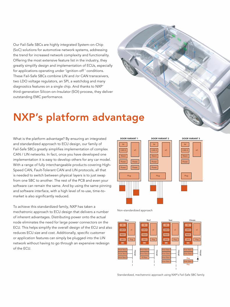
What is the platform advantage? By ensuring an integrated and standardized approach to ECU design, our family of Fail-Safe SBCs greatly simplifies implementation of complex CAN / LIN networks. In fact, once you have developed one implementation it is easy to develop others for any car model. With a range of fully interchangeable products covering High-Speed CAN, Fault-Tolerant CAN and LIN protocols, all that is needed to switch between physical layers is to just swap from one SBC to another. The rest of the PCB and even your software can remain the same. And by using the same pinning and software interface, with a high level of re-use, time-to-market is also significantly reduced.
To achieve this standardized family, NXP has taken a mechatronic approach to ECU design that delivers a number of inherent advantages. Distributing power onto the actual node eliminates the need for large power connectors on the ECU. This helps simplify the overall design of the ECU and also reduces ECU size and cost. Additionally, specific customer or application features can simply be plugged into the LIN network without having to go through an expensive redesign of the ECU.
Our Fail-Safe SBCs are highly integrated System-on-Chip (SoC) solutions for automotive network systems, addressing the trend for increased network complexity and functionality. Offering the most extensive feature list in the industry, they greatly simplify design and implementation of ECUs, especially for applications operating under ‘ignition-off ’ conditions. These Fail-Safe SBCs combine LIN and /or CAN transceivers, two LDO voltage regulators, an SPI, a watchdog and many diagnostics features on a single chip. And thanks to NXP’ third-generation Silicon-on-Insulator (SOI) process, they deliver outstanding EMC performance.
DOOR VARIANT 1
5V
CAN X
Watch
Power
Power
Plug
uC
Power
Power
DOOR VARIANT 2
5V
CAN X
Watch
Power
Power
Plug
uC
DOOR VARIANT 3
5V
CAN X
Watch
Power
Plug
uC
Non-standardized approach
Door
LIN
Bus
Driver Slave 1
Driver Slave 2
Driver Slave 3
SBC
5V
CAN X
Watch
LIN X
uC
Plug
SBC
5V
CAN X
Watch
LIN X
uC
Plug
SBC
5V
CAN X
Watch
LIN X
uC
Plug
SBC
5V
CAN X
Watch
LIN X
uC
Plug
Roof
LIN
Bus
Driver Slave 1
Driver Slave 2
I/O Slave
Seat
LIN
Bus
Driver Slave 1
Driver Slave 2
Driver Slave 3
Driver Slave 3
Climate
LIN
Bus
Driver Slave 1
Driver Slave 2
Driver Slave 3
Plug
Play
Standardized, mechatronic approach using NXP’s Fail-Safe SBC family
NXP’s platform advantage

Safe under all conditions
It is not just ease of design-in where our Fail-Safe SBCs excel. They also incorporate critical fail-safe and diagnostic functions – a feature set unique to NXP. A fully integrated fail-safe system controller ensures any conceivable local ECU failure stays local, while an extensive set of SPI readable diagnostic features provides detection, detailed reporting and rigorous error handling on CAN and LIN bus failures.
The extensive set on-chip of SPI readable diagnostics features allows rigorous error handling. Detection and detailed error reporting on CAN and LIN bus failures (e.g. shorts to GND/BAT, open bus wires etc.) ensure any failure can be easily handled, while TxD dominant and RxD recessive clamping as well as RxD to TxD short detection prevent bus deadlocks.
A host of features to ensure robust system operation are available including, ECU two-level ground-shift detection, over-temperature warning, ECU battery monitoring (for example to detect chattering battery contact or to save data before microcontroller power down) and signaling of potential RAM-retention errors due to low microcontroller VCC. Other features include guaranteed ramp down of the microcontroller voltage in case of a soft restart, detection of cyclic ECU problems and Global Enable pin to control safety critical hardware.
If a failure condition occurs the SBC will detect, report and ultimately switch to a low-power fail-safe mode, reducing power consumption and interference with the rest of the network. This is an important factor with the increasing number of bus nodes in today’s cars. At the same time,
alternative application hardware can be activated to enable a ‘limp home’ capability. The result – no more drained batteries for parked cars, or potentially dangerous network deadlocks.
Our Fail-Safe SBC family also incorporates a selective sleep mode offering a versatile way to create partial networks. This function allows traffi c to continue between nodes that must remain active, for instance central locking, without disturbing the rest of the network when the ignition is switched off. All that is required to re-activate nodes in Selective Sleep is a simple ‘wake-up’ message. This further reduces overall power consumption, especially under ‘ignition-off’ conditions. What’s more, integrating Selective Sleep into existing networks is simplicity itself. Just add an NXP Fail-Safe SBC where you need partial networking capability and the rest of the network can stay the same.
uC(unpowered)
SPI
VCC “off”
IgnitionKey
BAT
CAN
UJA1065“Invisible”
uC(active)
SPI
VCC “on”
UJA1065“Active”
uC(active)
SPI
VCC “on”
UJA1065“Active”
Unpowered ECU Communication No Wake-upuntil Global Wake-up Message
uC(unpowered)
SPI
VCC “off”
UJA1065“Selective
Sleep”
uC(stop)
SPI
VCC “on”
UJA1065“SelectiveStandby”
Selective sleep mode

www.nxp.com
© 2006 Koninklijke Philips Electronics N.V.
All rights reserved. Reproduction in whole or in part is prohibited without the prior written consent of the copyright owner. The
information presented in this document does not form part of any quotation or contract, is believed to be accurate and reliable
and may be changed without notice. No liability will be accepted by the publisher for any consequence of its use. Publication
thereof does not convey nor imply any license under patent- or other industrial or intellectual property rights.
Date of release: September 2006
Document order number: 9397 750 15751
Printed in the Netherlands
NXP Semiconductors is in the process of being established as a separate legal entity in various countries worldwide. This process will be finalized in the course of 2006.
BAT42
BAT14
SYSINH
V3
INH/LIMP
INTN
TEST
SCK
SDI
SDO
SCS
RTLIN
LIN
TXDL
RXDL
GND
WAKE
32
27
29
30
17
7
16
11
9
10
12
26
25
3
5
23
18
V1
V2
RSTNEN
RTH
CANH
CANL
TXDC
RXDC
4
20
68
24RTL19
21
22
13
14
SBCFAIL-SAFESYSTEM
V1 MONITOR
RESET/EN
WATCHDOG
OSCILLATOR
GND SHIFTDETECTOR
BATMONITOR
V1
V2
FAULTTOLERANT
CANTRANSCEIVER
LIN
SPI
CHIPTEMPERATURE
WAKE
INH
BAT42BAT42
V2
001aad803
UJA1061
Block diagram UJA1065
BAT42
BAT14
SYSINH
V3
INH/LIMP
INTN
TEST
SCK
SDI
SDO
SCS
RTLIN
LIN
TXDL
RXDL
GND
WAKE
SENSE32
27
29
30
17
7
16
11
9
10
12
26
25
3
5
23
18
31
V1
V2
RSTNEN
SPLIT
CANH
CANL
TXDC
RXDC
4
20
68
24
21
22
13
14
SBCFAIL-SAFESYSTEM
V1 MONITOR
RESET/EN
WATCHDOG
OSCILLATOR
GND SHIFTDETECTOR
BATMONITOR
V1
V2
HIGHSPEED
CAN
LIN
SPI
CHIPTEMPERATURE
WAKE
INH
BAT42BAT42
V2
001aac305
UJA1065
Block diagram UJA1061

32-bit ARM microcontroller families for in-vehicle systems SJA2xxx
Key featuresÑ Powerful 32-bit ARM microcontrollers Ñ Up to 2 Mbytes Flash with source code protection and
2 Mbits/s programming Ñ Integrated EEPROM and scalable SRAM sizes Ñ Up to 6 CAN 2.0B channels with global acceptance fi lter for
high performance gateway functionality Ñ LIN 2.0 master controller realized in hardware for low CPU loadÑ UARTs with local message buffers to increase effi ciencyÑ Universal 32-bit timers with capture and compare registers
linked to I/OsÑ 3.3 V and 5 V analog inputs, ADCs with 10-bit accuracyÑ Modulation and sampling control system for light dimming
and electrical motor controlÑ Real-time clock with 32 kHz crystal and dedicated
(battery) supply Ñ Full-duplex SPI with receive and transmit buffers and
message queues Ñ External 8-, 16-, or 32-bit bus with four memory banks Ñ Operating temperature range -40 to +125 °C ambientÑ Variety of packages, from low-pin-count (LPC) to
208 pins and more
Key benefi tsÑ Automotive quality – AEC-Q100 and beyond - maximized test coverage to virtually 100% - intrinsic robust processes and technologies - product verifi cation to limits of process settingsÑ Low EMCÑ Extensive power management with ultra-low-power modesÑ Convenience and fl exibility of scalable embedded SRAM
and Flash memory in pin-compatible packagesÑ Frees up CPU with dedicated hardware support for low-
latency FlexRay, CAN, LIN and SPI message handlingÑ Use same controllers for different applications - diverse features and packages offering various pin counts
Key applicationsÑ Gateway and combined body control / gateway systemsÑ FlexRay and safety-related applicationsÑ Driver assistanceÑ Any other applications where high performing and cost
effi cient automotive microcontrollers are required
Only solutions offering powerful processing capability and fast memory allow you to take full control of in-vehicle applications. Choose from our range of advanced, feature-packed 32-bit ARM microcontroller products. Select the performance, fl exibility and reliability you need to stay in pole position when creating systems such as advanced car gateways, safety and control networks.
Powerful processors pave way to enhanced automotive features

With hundreds of successful ARM implementations behind us, you know you can rely on our progressive technology to provide you with the right solutions for the job. And of course NXP keeps right up to date with the latest industry requirements, both in standards and functionality. In line with this, our portfolio includes the SJA25xx and SJA20xx families of powerful, automotive-qualified 32-bit ARM microcontrollers, ensuring your systems can easily handle the demands of modern vehicle electronics.
These families address a number of key industry trends and needs: • Non-proprietary cores – development tools and software
readily available from a variety of companies• Migration from 16- to 32-bit microcontroller performance• High bandwidth networks enable the move from application
to location-based modules – distributed systems• Autosar software support• Increased need for continuous improvements in product
quality• Greater integration to reduce the number of components
and modules in the car – requires more powerful microcontrollers
• Fully reliable systems needed to manage the increasing complexity and safety requirements
• Demand for driver assistance applications to increase both safety and comfort
Outstanding flexibility and performanceOur solutions give designers the highest level of flexibility for implementing and customizing on-chip peripheral blocks. This is due to a comprehensive re-use design approach, which influences all software and hardware functionality.
An extensive library of peripherals includes high performance CAN gateway blocks, LIN 2.0 master controllers, FlexRay v2.1 communication controllers, PWM modules for light dimming and electrical motor control, real-time clocks and ultra low power modes.
In addition, all our dedicated automotive microcontrollers are qualified to, and beyond, AEC-Q100. Dedicated automotive test, qualification and production flows are used to ensure superior quality and smallest PPM levels.
Stacks of memoryThe SJA20xx and SJA25xx families feature a wide variety of SRAM sizes, along with a 16 Kbyte EEPROM module and up to 2 Mbytes of on-chip, robust 2-transistor Flash program memory. Supporting both fast in-system programming via a 4 Mbits/s JTAG interface and in-application programming capability (for example, via CAN or UART connections), the Flash memory can also be protected to disable read access to the program source code. The SJA25xx controllers also feature tightly coupled memory (TCM) as well as multi-level AHB-buses to significantly boost system performance.
Software supportNXP fully supports the Autosar compliant communication driver throughout our automotive 32-bit product portfolio. A range of OSEK compliant real-time operating systems, CAN, LIN and FlexRay drivers, and embedded software components are also available for automotive applications. Additionally, several software vendors can provide a variety of software development tools.

6 CANGlobal Acceptance Filter FullCAN receive mode Triple Transmit buffers
32bit ARM980MHz
VICwith 16 prioritylevels & up to 24 external interrupts
512/768kB Flashwith Source CodeProtection, programmableat 4Mb/s
8 LIN 2.0 Masters Message buffers LIN message optimized
3 SPI16bit, Tx/Rx FIFOs
WatchDog32bit, with timerchange protection
64kB SRAM
Ringoscillatorfor power saving modes
2 UARTswith localmessage buffers
4 PWM6 channels each, 16bit
FlexRay v2.1 communications controllerBus Interface
8, 16 or 32bit data,26bit address,up to 8 memory banks
3 ADCs16/8/8 channels, 10bit4 timers
32bit, 4 cap/match register each
up to 96 GPIO
32-bit ARM9 microcontrollers with embedded FlexRay controller SJA25xx SJA25xx devices are powerful 32-bit ARM9 microcontrollers with an embedded and fully integrated two-channel FlexRay v2.1 communications controller. Now you can enable FlexRay with a lower component count and an increased effective usable memory. Also, their scalable and fl exible message handling provides cost- and performance-optimized solutions.
32-bit ARM7 body controller with IVN gateway functionality SJA2020 The fi rst microcontroller on the market supporting up to 4 LIN master controllers and 6 CAN 2.0B channels. A unique Global Acceptance Filter ensures extremely short transfer latency times for all CAN channels. State-of-the-art SPI and external bus interfaces enable rapid access to multimedia networks such as MOST and IDB-1394. A starter kit contains prototyping board and demonstration software drivers along with the chip itself.
A growing family
SJA2510 block diagram

www.nxp.com
© 2006 Koninklijke Philips Electronics N.V.
All rights reserved. Reproduction in whole or in part is prohibited without the prior written consent of the copyright owner. The
information presented in this document does not form part of any quotation or contract, is believed to be accurate and reliable
and may be changed without notice. No liability will be accepted by the publisher for any consequence of its use. Publication
thereof does not convey nor imply any license under patent- or other industrial or intellectual property rights.
Date of release: September 2006
Document order number: 9397 750 15757
Printed in the Netherlands
NXP Semiconductors is in the process of being established as a separate legal entity in various countries worldwide. This process will be finalized in the course of 2006.
ARM
CORE
MIPS Flash RAM CAN LIN FlexRay A/D PWM Pins Silicon
SJA2020/xxx Family
7TDMI 54128kB 384kB
24kB 6 4 - 4 - 144 Now
FlexRay Prepared(via full width external bus interface)
Gateway, general purpose Released
SJA2010/xxx Family
7TDMI 54256kB 768kB
16kB 48kB
6 8 - 32 24 144 - 208 Now
Gateway, general purpose Release: Q1 2007
SJA251x/xxx Family
‘968’...90
256kB 768kB
16kB 64kB
1 - 6 1 - 8 1 - 2 16 - 48 6 - 24 80 - 176 Now
FlexRay Embedded Gateway, general purpose Release: Q2 2007
Automotive MCU Product OverviewDesigned for Automotive (low EMC, low power, AEC-Q100 grade I and II)Dedicated automotive functionality (gateway, FlexRay, advanced power modes)Board support packages include software drivers and examples
CAN AUTOSAR

Vehicle body and gateway controller SJA2010
FeaturesÑ 32-bit ARM7, running at up to 60 MHzÑ 512/768 Kbytes embedded Flash with source code
protection and 4 Mbits/s fast programming capabilityÑ 40 Kbytes SRAMÑ CAN 2.0B compliant with FullCAN receive mode and triple
transmit buffersÑ 6 CAN controllers and 8 LIN 2.0 master controllersÑ 2 UARTS and 3 full-duplex SPI channelsÑ Real time clock with on-chip 32 kHz crystal oscillator and
battery supplyÑ 4 x 32-bit timers, each with four capture and compare
registersÑ 18 level-sensitive external interrupt pinsÑ 32 analog input pinsÑ 24 PWM outputs, suitable for light dimming and brushless
DC motor controlÑ Up to 160 general purpose I/OsÑ Internal programmable ringoscillator for power saving mode Ñ LQFP144/LQFP208Ñ LQFP176 on requestÑ Automotive AEC Q100 qualifi edÑ Temperature range: -40 + 105º ambient
The 32-bit ARM7 microcontroller SJA2010 includes dedicated hardware for IVN communication, making it the ideal solution for high-performance automotive body control and gateway systems as well as combined body control and gateway applications.
It supports specifi c hardware for 6 CAN channels and 8 dedicated LIN 2.0 master controllers, enabling high performance network communication with minimal CPU load.
Furthermore the SJA2010 features 4 versatile PWM modules with 6 outputs each, useful for applications such as light dimming. Direct coupling between the PWM modules and the A/D converters also makes the SJA2010 ideal for brushless DC motor control.
Benefi tsÑ Powerful, fl exible solution with extensive functionality and I/OsÑ Hardware support for CAN and LIN Ñ Same microcontroller can be used for multiple applications
The SJA2010 is a 32-bit ARM7-based microcontroller for automotive body control and gateway applications. Featuring scalable Flash memory, dedicated in-vehicle network interfaces and a compelling peripheral set in a range of package options, the SJA2010 provides designers with the highest level of fl exibility for implementing and customizing the on-chip peripherals.
Controlling the body
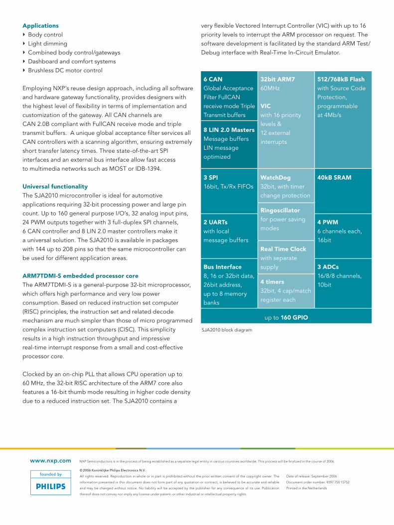
www.nxp.com
© 2006 Koninklijke Philips Electronics N.V.
All rights reserved. Reproduction in whole or in part is prohibited without the prior written consent of the copyright owner. The
information presented in this document does not form part of any quotation or contract, is believed to be accurate and reliable
and may be changed without notice. No liability will be accepted by the publisher for any consequence of its use. Publication
thereof does not convey nor imply any license under patent- or other industrial or intellectual property rights.
Date of release: September 2006
Document order number: 9397 750 15752
Printed in the Netherlands
NXP Semiconductors is in the process of being established as a separate legal entity in various countries worldwide. This process will be finalized in the course of 2006.
ApplicationsÑ Body controlÑ Light dimmingÑ Combined body control/gatewaysÑ Dashboard and comfort systemsÑ Brushless DC motor control
Employing NXP’s reuse design approach, including all software and hardware gateway functionality, provides designers with the highest level of flexibility in terms of implementation and customization of the gateway. All CAN channels are CAN 2.0B compliant with FullCAN receive mode and triple transmit buffers. A unique global acceptance filter services all CAN controllers with a scanning algorithm, ensuring extremely short transfer latency times. Three state-of-the-art SPI interfaces and an external bus interface allow fast access to multimedia networks such as MOST or IDB-1394.
Universal functionalityThe SJA2010 microcontroller is ideal for automotive applications requiring 32-bit processing power and large pin count. Up to 160 general purpose I/O’s, 32 analog input pins, 24 PWM outputs together with 3 full-duplex SPI channels, 6 CAN controller and 8 LIN 2.0 master controllers make it a universal solution. The SJA2010 is available in packages with 144 up to 208 pins so that the same microcontroller can be used for different application areas.
ARM7TDMI-S embedded processor coreThe ARM7TDMI-S is a general-purpose 32-bit microprocessor, which offers high performance and very low power consumption. Based on reduced instruction set computer (RISC) principles, the instruction set and related decode mechanism are much simpler than those of micro programmed complex instruction set computers (CISC). This simplicity results in a high instruction throughput and impressive real-time interrupt response from a small and cost-effective processor core.
Clocked by an on-chip PLL that allows CPU operation up to 60 MHz, the 32-bit RISC architecture of the ARM7 core also features a 16-bit thumb mode resulting in higher code density due to a reduced instruction set. The SJA2010 contains a
very flexible Vectored Interrupt Controller (VIC) with up to 16 priority levels to interrupt the ARM processor on request. The software development is facilitated by the standard ARM Test/Debug interface with Real-Time In-Circuit Emulator.
6 CANGlobal Acceptance Filter FullCAN receive mode Triple Transmit buffers
32bit ARM760MHz
VICwith 16 prioritylevels &12 external interrupts
512/768kB Flashwith Source CodeProtection, programmableat 4Mb/s
8 LIN 2.0 Masters Message buffers LIN message optimized
3 SPI16bit, Tx/Rx FIFOs
WatchDog32bit, with timerchange protection
40kB SRAM
Ringoscillatorfor power saving modes
2 UARTswith localmessage buffers
4 PWM6 channels each, 16bit
Real Time Clockwith separate supplyBus Interface
8, 16 or 32bit data,26bit address,up to 8 memory banks
3 ADCs16/8/8 channels, 10bit4 timers
32bit, 4 cap/match register each
up to 160 GPIO
SJA2010 block diagram

IVN gateway controller SJA2020
Key featuresÑ 32-bit ARM7 microcontroller running at up to 60 MHzÑ Fully qualifi ed to AEC Q100 standard for automotive
semiconductorsÑ 256/384 Kbyte embedded Flash with source code protection
and 4 Mbit/s fast programmingÑ On-chip 24 Kbyte static RAM may be used for code
and/or data storageÑ 6 CAN channels with global acceptance fi lterÑ 4 LIN master controllers implemented in hardwareÑ 4 industry standard ‘450’ UARTs and one ‘550’ UART with
16 bytes transmit and receive FIFO Ñ 4-channel 10-bit A/D converterÑ Real-time clock with on-chip 32 kHz crystal oscillator and
dedicated (battery) supplyÑ Three full-duplex SPIÑ 32-bit watchdog with timer change protectionÑ External 8-, 16- or 32-bit bus with four memory banksÑ Up to 94 general purpose I/OsÑ Ambient operating temperature range from -40 to +105°CÑ Dual Supply: CPU 1.8 V ± 5 %, I/O 2.7 V to 3.6 V, 5V tolerantÑ On-board ring oscillator for advanced power saving modesÑ LQFP 144 pin package
The SJA2020 network communication gateway is NXP’s fi rst dedicated 32-bit ARM-based automotive microcontroller. Gateway ICs are essential to deal with the additional computing and memory demands created by increasingly complex in-vehicle networks. The SJA2020 has been developed through close relationships with key automotive industry players to ensure it is a cost-effective high-performance solution. Based on our proven embedded core and automotive expertise, it enables optimized receiving, composing, routing and transmission of network messages on different in-vehicle serial bus systems.
Key benefi tsÑ Effi cient CAN message handling with maximum fl exibilityÑ Dedicated LIN message handling frees up CPU processing
power for applicationsÑ Extensive feature list allows designers to use the same
microcontroller for different applications
The SJA2020 is a 32-bit ARM7-based automotive gateway controller, featuring fast, robust embedded Flash, dedicated in-vehicle network interfaces and a compelling peripheral set in a 144 pin package. With hardware supporting up to 6 CAN and 4 LIN interfaces, the SJA2020 delivers excellent performance for the emerging digital IVN market.
Take complete control in the digital IVN market

www.nxp.com
© 2006 Koninklijke Philips Electronics N.V.
All rights reserved. Reproduction in whole or in part is prohibited without the prior written consent of the copyright owner. The
information presented in this document does not form part of any quotation or contract, is believed to be accurate and reliable
and may be changed without notice. No liability will be accepted by the publisher for any consequence of its use. Publication
thereof does not convey nor imply any license under patent- or other industrial or intellectual property rights.
Date of release: September 2006
Document order number: 9397 750 15753
Printed in the Netherlands
NXP Semiconductors is in the process of being established as a separate legal entity in various countries worldwide. This process will be finalized in the course of 2006.
Key applicationsÑ Car gateways with up to 6 CAN and up to 4 LIN networksÑ Body control requiring 32-bit CPU performance
Employing our reuse design approach, including all software and hardware gateway functionality, provides designers with the highest level of flexibility in terms of implementation and customization of the gateway. The dedicated gateway hardware supports up to 6 CAN channels and 4 dedicated LIN masters, delivering high-performance gateway functionality with minimal CPU load. A unique Global Acceptance Filter servicing all CAN controllers with a hardware accelerated scanning algorithm ensures extremely short transfer-latency times. All CAN channels are CAN 2.0B compliant with FullCAN receive mode and triple transmit buffers. The 4 dedicated LIN master controllers enable CAN/LIN gateway functionality, while three state-of-the-art SPI interfaces and an external bus interface allow fast access to multimedia networks such as MOST or IDB-1394.
The SJA2020 features a robust 256 kB/384 kB Flash memory system with fast In-System Programming (ISP) via a JTAG interface and In-Application Programming (IAP) via a serial port (e.g. CAN), providing flexibility for data storage field upgrades and EEPROM emulation. And with up to 94 general purpose I/Os, 5 UARTs, 4 32-bit timers - each with 4 capture/match registers - and a 4-channel, 10-bit ADC, the SJA2020 meets a wide variety of automotive application needs.
An extensive range of OSEK compliant real time operating systems, CAN drivers and embedded software components are available for automotive applications, as are a variety of software development tools provided by several vendors. The SJA2020 starter kit also includes a prototyping board together with demo software drivers.
ARM7TDMI-S embedded processor CoreThe ARM7TDMI-S is a general-purpose 32-bit microprocessor, which offers high performance and very low power consumption. Based on reduced instruction set computer (RISC) principles, the instruction set and related decode mechanism are much simpler than those of micro
programmed complex instruction set computers (CISC). This simplicity results in a high instruction throughput and impressive real-time interrupt response from a small and cost-effective processor core.
Clocked by an on-chip PLL that allows CPU operation up to 60 MHz, the 32-bit RISC architecture of the ARM7 core also features a 16-bit thumb mode resulting in higher code density due to a reduced instruction set. The SJA2020 contains a very flexible Vectored Interrupt Controller (VIC) with up to 16 priority levels to interrupt the ARM processor on request. The software development is facilitated by the standard ARM Test/Debug interface with Real-Time In-Circuit Emulator.
6 CANGlobal Acceptance Filter FullCAN receive mode Triple Transmit buffers
32bit ARM760MHzVIC with 16 prioritylevels &12 external interrupts
256kB/384kB Flashin 32/48 sectorsEEPROM emulationprogramming at 4Mb/s
4 LIN Masters Message buffers LIN message optimized
WatchDog 24kB SRAM
3 SPI16bit, Tx/Rx FIFOs
Real Time Clockwith separate supply
Bus Interface8, 16, or 32bit width
4 UART 4 timers32bit, 4 cap/match each
ADC4 channel, 10bit
up to 94 GPIO
SJA2020 block diagram

FlexRay transceiver TJA1080As the world’s fi rst fully featured FlexRay transceiver, the TJA1080 offers a host of additional functionality on top of the standard and optional features specifi ed by FlexRay v2.1. Uniquely it can be used in both node and active star confi gurations.
Key featuresÑ Data rates up to 10 Mbits/sÑ ECU low power managementÑ Local and remote wake-up capabilityÑ Mode control via two dedicated control inputsÑ Auto I/O-level adaptation with Vio inputÑ Bus Guardian interfaceÑ Error indicationÑ 42 V compliantÑ - 40 °C to + 150 °C junction operating temperature rangeÑ 8 kV ESD protection on bus pins
FlexRay-enabled 32-bit ARM9 MCU SJA2510The SJA2510 is a powerful 32-bit ARM9 MCU with an embedded and fully integrated two-channel FlexRay v2.1 communications controller.
Key featuresÑ 32-bit ARM968E core, up to 80 MHzÑ High performance multi-layer busÑ Up to 1 Mbyte Flash memory and up to 64 kbytes RAMÑ Two-channel FlexRay version 2.1 communications controllerÑ Six CAN 2.0B controllersÑ Eight LIN 2.0 master controllersÑ Three Q-SPIsÑ Wide range of on-chip features including external bus
interface, PWM modules, UARTs, 3.3 V and 5 V ADCs, ring oscillator, JTAG interface, watchdog timer and pin multiplexing
Ñ Multiple advanced power modesÑ - 40 °C to + 150 °C junction operating temperature rangeÑ LQFP144 package
By combining the FlexRay transceiver TJA1080 with the FlexRay-enabled microcontroller SJA2510, NXP Semiconductors delivers a complete system solution with a low component count and more usable memory. Its scalable and fl exible message handling provides cost- and performance-optimized solutions, while the sharing of the protocol engine IP with Freescale ensures full interoperability.
Achieve maximum performance and interoperability in automotive applications
Complete FlexRay v2.1silicon system solution

• Longest semiconductor history in FlexRay
• Providers of FlexRay development silicon
FlexRay SemiconductorCore Partners
• Avoids issues typical of a new standard
• Freedom of choice of components
• Experience from early IP incorporated
• IP designs tested by Consortium Test WG
Interoperability IP Licenses Available
Joint IP Developmentfor FlexRay Controllers
• FlexRay v2.1 compliant• Reference model• Protocol engine• Compatibility model
FlexRay provides the ideal protocol for next-generation control applications in the car. Aimed primarily at powertrain and chassis systems, FlexRay has the flexibility, scalability and high speed needed in today’s advanced systems including braking, steering and active chassis management.
The development, compatibility and availability of FlexRay solutions is being supported by Philips and Freescale – core
members of the FlexRay Consortium. By sharing our FlexRay IP, we are helping drive the adoption of FlexRay networks into the vehicle.
The cooperation reflects the drive from both companies to offer developers the first full interoperable solutions compliant with FlexRay v2.1, while maintaining freedom of choice of components.
www.nxp.com
© 2006 Koninklijke Philips Electronics N.V.
All rights reserved. Reproduction in whole or in part is prohibited without the prior written consent of the copyright owner. The
information presented in this document does not form part of any quotation or contract, is believed to be accurate and reliable
and may be changed without notice. No liability will be accepted by the publisher for any consequence of its use. Publication
thereof does not convey nor imply any license under patent- or other industrial or intellectual property rights.
Date of release: September 2006
Document order number: 9397 750 15758
Printed in the Netherlands
NXP Semiconductors is in the process of being established as a separate legal entity in various countries worldwide. This process will be finalized in the course of 2006.
NXP and Freescale - strong partners for FlexRayTM

FlexRay node and star transceiver TJA1080
Key featuresÑ Datatransferfrom1Mbit/supto10Mbits/sÑ ExcellentEMCperformance -VerylowElectroMagneticEmissiontosupport
unshieldedcable -Differentialreceiverwithhighcommon-moderangefor
excellentElectroMagneticImmunityÑ Canbeusedforlinearpassivebustopologiesaswellas
activestartopologiesÑ Lowpowermanagementincludingtwoinhibitswitches
enablingpowerconsumptionoptimizedECUdesignÑ VerylowcurrentinSleepandStandbymodeÑ AutonomouspowermodeswhenusedinactivestarsÑ Localwake-upinputaswellasremotewake-upcapability
viatheFlexRaybusÑ Wake-upsourcerecognitionÑ Extensivediagnosis(overtemperatureandundervoltage
detection,wake-upsourceindication,errorindication)Ñ Detectionandfail-safemodeincaseofanundervoltage
onpinsVBAT,VCCorVIO
Ñ ±8kVESDprotection(HBM)
Ñ Protectedagainsttransientsinautomotiveenvironment(ISO7637classCcompliant)
Ñ Protectedagainstshort-circuitonbuslinesÑ Passivebehaviorofbuslinesintheeventthattransceiver
isnotpoweredÑ Supports2.5,3.0,3.3and5Vmicrocontrollersand
automaticallyadaptstointerfacelevelsÑ Canbeusedin14Vand42VsystemsÑ InterfacetooptionalBusGuardianforbusaccesssupervisionÑ Automotiveproductqualificationinaccordancewith
AEC-Q100
Astheworld’sfirstsiliconsolutionfortheFlexRayelectricalphysicallayer,thehigh-speedcommunicationsystemtransceiverTJA1080highlightsFlexRay’spowerandversatility.Thiskeydeviceishelpingdrivenewadvancedcommunicationssystemintotoday’sandtomorrow’scarsbyofferinganextensivefeatureset,excellentEMCperformanceandtheuniquepossibilitytocreateactivestarcouplers.
The robust choice in communicating with complete FlexRay architectures
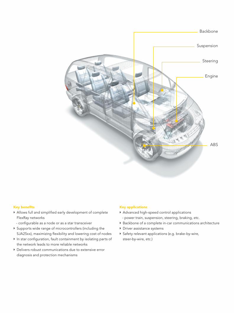
Key benefitsÑ Allowsfullandsimplifiedearlydevelopmentofcomplete
FlexRaynetworks -configurableasanodeorasastartransceiverÑ Supportswiderangeofmicrocontrollers(includingthe
SJA25xx),maximizingflexibilityandloweringcostofnodesÑ Instarconfiguration,faultcontainmentbyisolatingpartsof
thenetworkleadstomorereliablenetworksÑ Deliversrobustcommunicationsduetoextensiveerror
diagnosisandprotectionmechanisms
Key applicationsÑ Advancedhigh-speedcontrolapplications -powertrain,suspension,steering,braking,etc.Ñ Backboneofacompletein-carcommunicationsarchitectureÑ DriverassistancesystemsÑ Safetyrelevantapplications(e.g.brake-by-wire,
steer-by-wire,etc.)
Suspension
Backbone
Engine
ABS
Steering

TRXD0
VIO
VBUF VBAT
INH2
INH1
SIGNALROUTER
TRANS-MITTER
BUSFAILURE
DETECTION
NORMALRECEIVER
INPUTVOLTAGE
ADAPTATION
OUTPUTVOLTAGE
ADAPTATION STATEMACHINE
001aae436
TJA1080
VCCVIO
BP
BM
TRXD1
TXD
RXD RXDINT
RXDINT
VBAT
ERRNRXEN
WAKE-UPDETECTION
OSCILLATOR
UNDERVOLTAGEDETECTION
WAKEOVER-
TEMPERATUREDETECTION
LOW-POWER
RECEIVER
TXENBGE
STBNEN
11
10
4102914
5
713
18
1
2
17
12
15
16
GND
6893
FlexRaysystemshavedevelopedrapidlyoverthelastfewyearsastheindustryfamiliarizesitselfwiththetechnology.BytakingasmartandflexibleapproachtobuildingnetworkarchitecturesalongwithFlexRay’sdeterministicbehavioraswellaserrorconfinementcapability,manufacturersaregainingfullydependablecommunications.Systemscanalsoeasilyincorporatemorenodesandnewapplicationsthankstothehighbandwidth,andoverallsystemcostsaredecreasing.
KeytothishasbeentheavailabilityofdevicessuchastheFlexRaytransceiverTJA1080.DrawingonourheritageasafoundingmemberoftheFlexRayconsortium,thistransceiveroffersanextensivefeatureset,excellentEMCperformanceaswellasstrongESDprotection.BycombiningbothFlexRaynodetransceiverandFlexRayactivestardeviceonasinglechip,theTJA1080alsosupportstheearlyandsimplifieddevelopmentofcompleteFlexRaynetworkarchitectures.
DevelopedinlinewiththeFlexRayelectricalphysicallayerspecificationV2.1Rev.A,itisprimarilyintendedforhigh-speedcommunicationsystemssupportingeverychosendatarateupto10Mbits/s.TheTJA1080alsoprovidesanadvancedinterfacebetweentheprotocolcontrollerandthephysicalbusinaFlexRaynetwork.
Robustcommunicationsaresecuredbyactivelymonitoringsystemperformanceusingdedicatederrorandstatusinformation(readablebyanymicrocontroller)alongwithinternalvoltageandtemperaturemonitoring.ABusGuardianinterfaceenablestheTJA1080tobeusedinsystemsthatrequireadditionalsupervisions.Whileinactivestarandnodeconfigurations,featuressuchassleepandstandbypowermodesservetheneedforautomotivepowermanagement.
TJA1080blockdiagram

www.nxp.com
© 2006 Koninklijke Philips Electronics N.V.
All rights reserved. Reproduction in whole or in part is prohibited without the prior written consent of the copyright owner. The
information presented in this document does not form part of any quotation or contract, is believed to be accurate and reliable
and may be changed without notice. No liability will be accepted by the publisher for any consequence of its use. Publication
thereof does not convey nor imply any license under patent- or other industrial or intellectual property rights.
Date of release: September 2006
Document order number: 9397 750 15746
Printed in the Netherlands
NXP Semiconductors is in the process of being established as a separate legal entity in various countries worldwide. This process will be finalized in the course of 2006.
001aaf472
VBAT
TJA1080
VCCVIO
TXENVBUF
TRXD1TRXD0
INH1
BMBP
GNDEN
WAKE
BGETXDSTBN
BAT5 V
VBAT
TJA1080
VCCVIO
TXENVBUF
TRXD1TRXD0
INH1
BMBP
GNDEN
WAKE
BGETXDSTBN
VBAT
TJA1080
VCCVIO
TXENVBUF
TRXD1TRXD0
INH1
BMBP
GNDEN
WAKE
BGETXDSTBN
001aaf471
SUPPLYFOR HOSTe.g. 3.3 V
HOST
COMMUNICATIONCONTROLLER
INH1VIO
TJA1080
BGESTBN
ENERRN
RXDTXEN
TXD
VCCVBAT
WAKE
BMBPGNDTRXD1TRXD0
BAT
5 V
Typicalnodeconfiguration
Typicalactivestarconfiguration

32-bit ARM9 MCU with embedded FlexRay v2.1 controller SJA2510
Key featuresÑ 32-bit ARM968E-S core running at up to 80 MHzÑ 32-bit multi-layer AHB-lite busÑ 2-channel FlexRay v2.1 communications controllerÑ Six CAN 2.0B controllers Ñ Eight LIN 2.0 master controllersÑ Large on-board memories - Separate 16 Kbyte Tightly Coupled Memories for data and
instructions - 32 and 16 Kbyte SRAMs - Up to 768 Kbyte fast Flash memoryÑ Three full-duplex Queued-Quad SPIs (Q-SPIs) Ñ Highly confi gurable system Power Management Unit (PMU) Ñ Extensive additional functionality including external bus
interface, PWM modules, UARTs, 3.3 V and 5 V ADCs, ring oscillator, JTAG interface, watchdog timer and pin multiplexing
Ñ Automotive qualifi ed (AEC-Q100 Grade I)Ñ LQFP100, LQFP128 and LQFP144 package options
Key benefi tsÑ Fully compliant with FlexRay Protocol Specifi cation v2.1Ñ More usable memory and reduced component countÑ Enables cost- and performance-optimized solutionsÑ Full interoperability with other FlexRay v2.1 certifi ed
solutions Ñ Wide range of development environments , communication
drivers, operating systems and board support packages including extensive third-party support
The SJA2510 is your highway to fast, reliable and cost-effi cient FlexRay systems. At its heart is a 32-bit ARM968E-S core, delivering up to 90 MIPS of processing power. For maximum performance, this powerful CPU is combined with Tightly Coupled Memory, fast Flash memory and a 32-bit multi-layer AHB-lite bus that enables parallel data transfer with minimal CPU involvement.
Fast and high-bandwidth, FlexRay is the networking solution to meet the demand for more and more advanced in-vehicle electronics systems. Our 32-bit microcontroller with embedded FlexRay communications interface SJA2510 ensures your systems deliver maximum performance at the right price with guaranteed interoperability.
Take control of fast, reliable and cost-effi cient FlexRay networks

Designed as a complete in-vehicle communications gateway, the SJA2510 is one of the first microcontrollers with a fully embedded FlexRay v2.1 controller. Highly flexible, the controller supports 1 or 2 channels with 10 Mbits/s data rates. Buffer sizes and numbers can be freely configured within a dedicated 16 Kbyte SRAM memory, giving you easy scalability and allowing your solution to grow as the application does. Furthermore, as the controller is fully interoperable with any FlexRay-certified transceiver, the SJA2510 can be easily combined with our FlexRay transceiver TJA1080 for rapid development of complete FlexRay systems.
The integrated FlexRay v2.1 communication controller features a Controller Host Interface (CHI) with DMA functionality for high performance with low CPU load. This also offers the highest flexibility for FlexRay buffer configuration. Within the
available memory space the number and size of message buffers can be freely configured, and the CHI even allows dynamic buffer configuration at run-time.
In addition, the SJA2510 includes six ISO 11898-compatible CAN 2.0B controllers featuring receive FullCAN mode, triple transmit buffers and data rates up to 1 Mbit/s. It also offers eight dedicated LIN 2.0 master controllers that realize many functions in hardware to reduce CPU load. Other communications interfaces include 2 industry-standard ‘550 UARTs, 2 Q-SPIs and three ADCs (1 x 16-channel and 2 x 8-channel).
To help reduce your development times, you can take advantage of the extensive technical support available from us and third-party suppliers. This includes evaluation boards, development environments, communications drivers, operating systems and demo application software. Communication stacks for the embedded FlexRay, CAN and LIN controllers and operating systems are also available from several reputable software companies.
www.nxp.com
© 2006 Koninklijke Philips Electronics N.V.
All rights reserved. Reproduction in whole or in part is prohibited without the prior written consent of the copyright owner. The
information presented in this document does not form part of any quotation or contract, is believed to be accurate and reliable
and may be changed without notice. No liability will be accepted by the publisher for any consequence of its use. Publication
thereof does not convey nor imply any license under patent- or other industrial or intellectual property rights.
Date of release: September 2006
Document order number: 9397 750 15756
Printed in the Netherlands
NXP Semiconductors is in the process of being established as a separate legal entity in various countries worldwide. This process will be finalized in the course of 2006.
6 CANGlobal Acceptance Filter FullCAN receive mode Triple Transmit buffers
32bit ARM980MHz
VICwith 16 prioritylevels &up to 24 external interrupts
512/768kB Flashwith Source CodeProtection, programmableat 4Mb/s
8 LIN 2.0 Masters Message buffers LIN message optimized
3 SPI16bit, Tx/Rx FIFOs
WatchDog32bit, with timerchange protection
64kB SRAM
Ringoscillatorfor power saving modes
2 UARTswith localmessage buffers
4 PWM6 channels each, 16bit
FlexRay v2.1 communications controllerBus Interface
8, 16 or 32bit data,26bit address,up to 8 memory banks
3 ADCs16/8/8 channels, 10bit4 timers
32bit, 4 cap/match register each
up to 96 GPIO
SJA2510 block diagram

Safe-by-Wire Plus™ solutions AU6102, UJA6203 and UJA6402
Key featuresÑ Two-wire bus system for sensor and deployment networks - Bi-directional master-slave communication - Slave devices powered by master via busÑ Flexible bus topology - Supports bus, tree, ring and daisy-chain topologiesÑ Highly effi cient protocol with minimum overhead - Selective deployment of up to 12 squibs within 200 µs - Data acquisition for 3 sensors (8 bits each) within 250 µs
(4 kHz) - Flexible diagnostic communicationÑ Fault-tolerant - Real-time recovery from bus wire shorts - Individual bit error checking using CRC - Data validation by transmitter guards against bus
collision errors - Independent ‘safi ng’ signal for deployable devicesÑ Variable bus speed (20, 40, 80 or 160 kbits/s) - Can even be changed ‘on-the-fl y’ - Slaves synchronize easily to bus speed given by master
Ñ Supports various sensor update confi gurations, including: - A mix of 4 kHz and 2 kHz sensors on the same bus - A mix of fast (2 kHz / 4 kHz) impact sensors and slow
(< 1 kHz) occupancy sensors on the same bus
To deliver the highest possible safety standards, automotive manufacturers are incorporating more and more safety features across their model ranges. Seat-belt pre-tensioners, multiple airbags and an array of sensors (impact, acceleration, pressure, occupancy, roll-over, etc.) are being combined into adaptive occupant restraint systems. Ensuring the right safety feature is activated at the right time requires quick, reliable communication between the restraints control module and all these sensors plus a host of deployment devices. The members of the Safe-by-Wire Plus consortium are leveraging their extensive combined knowledge and experience to refi ne the global networking standard for these communications that will bring the highest safety levels to all vehicles.
The Safe-by-Wire Plus consortium has defi ned a global networking standard for automotive occupant safety systems that merges the best features from existing Safe-by-Wire and BST developments. This new industry standard will benefi t both automotive manufacturers and consumers by easing the integration of advanced safety features, leading to safer vehicles throughout the price spectrum.
Connectivity to ensure occupant safety

The Safe-by-Wire Plus consortium comprises leading automotive systems and component suppliers, uniting the previous activities of the Safe-by-Wire consortium (Analog Devices Inc., Autoliv Inc., Delphi Corporation, Key Safety Systems, NXP, Special Devices Inc. and TRW Automotive) and the BST group (Bosch, Continental Temic and Siemens VDO Automotive). The key goal was to combine the independent and competing automotive safety bus specifi cations into a single global standard, capturing the best of both previous implementations. Through component standardization, the new consortium expects to reduce development costs and enable automotive manufacturers to leverage the economies of scale – allowing more effi cient integration of advanced safety features. This will ultimately contribute to safer vehicles at all price levels.
The consortium has recently released version 2.0 of the Automotive Safety Restraints Bus (ASRB 2.0) specifi cation. Based on the Safe-by-Wire ASRB 1.0 specifi cation, it also includes some of the concepts from the work conducted by the BST group. The new specifi cation is fully compliant with the Safe-by-Wire physical layer, preserving compatibility with Safe-by-Wire (ASRB 1.0) systems and components already being developed. The consortium has submitted the ASRB 2.0 specifi cation to the appropriate ISO working group for consideration as a global standard (ISO 22896). Furthermore, the Safe-by-Wire Plus solution is a royalty-free standard.
NXP developed a complete set of Safe-by-Wire Plus interface ICs for restraint control modules and sensor/deployment slaves. Designed for use in today’s advanced
automotive safety systems, these devices have the fl exibility to accommodate tomorrow’s innovations. The portfolio is fully compliant with the Safe-by-Wire Plus defi ned standard, simplifying the design of passenger restraint systems, allowing rapid customization and reducing costs so that the highestprotection levels are available in all vehicles.
Deployment slave AU6102The AU6102 is an engineering prototype version of a single-chip parallel bus interface for pyrotechnical low-energy igniters. This squib driver includes a charge pump for storage of the fi ring energy in an external capacitor and provides full diagnostics for the initiator bridge.
Ñ Safe deploy control by two independent deploy switchesÑ Energy reserve controlÑ Diagnostics for deploy switches and initiator bridgeÑ OTP memory for address and traceability data
EnergyReserveCapacitor
Initiator bridge
Safe-by-Wire Plus bus wires
AU6102
Smart squib

Raw-data sensor slave UJA6203 The UJA6203 is a single-chip parallel sensor interface capable of providing communication between an analog impact sensor and the Safe-by-Wire Plus bus. Analog inputs from one or two crash sensors are received by the UJA6203, converted into a Safe-by-Wire Plus compatible digital format and sent as raw data over the bus. The device itself is self-powered, but it has a built in 5 V regulator capable of supplying external loads.
Ñ Raw data Safe-by-Wire Plus sensor bus interfaceÑ Built-in 10-bit 2-channel ADC Ñ Powered directly from busÑ Regulated 5 V outputÑ Built-in diagnostic capabilities and supports sensor
health monitorÑ OTP memory for address, set-up and traceability dataÑ SO8 package
Dual channel sensor bus master UJA6402NXP’s UJA6402 dual-channel sensor bus master provides the interface between two Safe-by-Wire Plus buses and a vehicle’s main occupant safety ECU. The master communicates with the Safe-by-Wire Plus sensor slaves via the bus and is controlled via the SPI port by a local ECU microcontroller. A fully self-contained solution, the UJA6402 incorporates Safe-by-Wire Plus data link controller and transceivers along with the required fl oating supplies and diagnostic capabilities.
Ñ Drives two independent Safe-by-Wire Plus busesÑ Supports sensor bus slavesÑ SPI port for direct microcontroller interface, 3.3 – 5 VÑ Fault-tolerantÑ Allows individual data length selection for each S-frame slot
(8 or 10 bit)Ñ Choice of 3- or 8-bit CRC for S-framesÑ HTSSOP32 packageÑ EMC compliant
ECU interface
Safe-by-Wire Plusbus channel 0
bus channel 1Safe-by-Wire Plus
3.3-5 V
16 V
SPI
UJA6402
ECU
µC
Raw data sensor interface
SensorSupply
SensorControl& Status
AnalogSignal(s)
Safe-by-Wire Plus bus wires
UJA6203
sensor

www.nxp.com
© 2006 Koninklijke Philips Electronics N.V.
All rights reserved. Reproduction in whole or in part is prohibited without the prior written consent of the copyright owner. The
information presented in this document does not form part of any quotation or contract, is believed to be accurate and reliable
and may be changed without notice. No liability will be accepted by the publisher for any consequence of its use. Publication
thereof does not convey nor imply any license under patent- or other industrial or intellectual property rights.
Date of release: September 2006
Document order number: 9397 750 15754
Printed in the Netherlands
NXP Semiconductors is in the process of being established as a separate legal entity in various countries worldwide. This process will be finalized in the course of 2006.
System advantagesReplacing conventional point-to-point connections with a Safe-by-Wire Plus bus brings numerous benefits to your system that reduce overall cost and increase flexibility.
Ñ Simplified wiring and cost-effective approach - Shorter cabling reduces weight - Smaller ECU connector saves space - Re-use of standardized components cuts development time - Standardization leads to high-volume multi-source
components
Ñ Future-proof open bus architecture simplifies system changes - Modify existing slaves - Use slaves from different sources - Change the number of slaves - Add new types of slaves
Ñ Electronic deploy interface supports safe system design - Airbag deployment only by bus message makes
handling safer - Individual, local deployment energy per airbag can
be de-powered for airbag suppression - Electronic identification of slaves allows check of
system integrity - Tamper resistant
P 0 P 1 P 0 P t
busvoltage
normal communicationsafing orinterrupt
Wire-A
Wire-B
6V 11V 3V0V
t
diff. busvoltage
6V 11V3V 0V
Absolute and differential signal
The Safe-by-Wire Plus specification can be downloaded from www.nxp.com/products/automotive/transceivers_sbcs/safe_by_wire_plus/


![[Tugas Materi] IC Datasheet](https://img.dokumen.tips/doc/110x75/55cf9680550346d0338be37c/tugas-materi-ic-datasheet.jpg)