Embed Size (px)
Citation preview

COGNEX®
DataMan® 300 SeriesQuick Reference Guide

ii DataMan 300 Quick Reference Guide DataMan 300 Quick Reference Guide iii
Sect ion Tit le • Page 21Gett ing Started
About DataMan 300 Series • For More Information • DataMan 300 Series Accessories • DataMan 300 Systems Page 41
DataMan Softw are Page 4 73Installing DataMan Software and Connecting the Reader • Start the Setup Tool • Troubleshooting • Setup Tool Menu Bar • Industrial Protocols • Test Mode • Triggering • Read Setups • Tuning • Image Filtering • Training the Reader • Scripting • Package Detection
1Connect ions, Opt ics, and Light ing Page 6 94
External Light Control • I/O Cable • High-Speed Output Lines • High-Speed Output Wiring • Ethernet M12 to RJ45 Cable • Acquisition Triggering
1Com pliance I nform at ion, W arnings and Not ices
Page 7 85Warnings and Notices • Compliance Statements • DataMan 300 Series Speciications
Set t ing Up Your DataManReader Layout • Installing the Lens • Installing a Filter • Installing a Filter in a Flat LED Front Cover • External Light Mounting Brackets • Setting Focus • Field of View and Reading Distances • Dimensions • DataMan 300 Series Imager Speciications
2 Page 1 0

4 DataMan 300 Quick Reference Guide DataMan 300 Quick Reference Guide 5
About DataMan 3 0 0 Series Readers For More I nform at ion...
DataMan 300 series readers are
high-performance, ixed-mount ID readers that among others offer the following advanced features:
• Highest Read Rates on 1-D and 2-D codes
• Most lexible optics and lighting
• Intelligent tuning and express setup
DataMan 300 series readers provide advanced Ethernet connectivity, support for serial RS-232 and discrete I/O, as well as advanced options for lighting and optics.
DataMan 300 series readers are packaged in a rugged, IP65-rated housing, and they provide numerous ease-of-use features, including one button to trigger and one to start tuning.
This document provides basic information about how to conigure and use DataMan 300 series readers. Additional information is available through the Windows Start menu or the Setup Tool Help menu after you install the DataMan software on your PC:
DataMan Fixed Mount Readers Reference is a complete online hardware reference for the DataMan ixed-mount ID readers. Cognex->DataMan Software v x.x->Documentation->English->DM300 Series
->Fixed Mount Reference Manual
DataMan Com m unicat ions & Program m ing Guide shows how to integrate your DataMan reader with your automation software and factory network.Cognex->DataMan Software v x.x->Documentation->Communications &
Programming
DataMan Reader Coniguration Codes provides printable 2-D codes that you can use to conigure the DataMan reader.Cognex->DataMan Software v x.x->Documentation->English->Reader Coniguration
Codes
DataMan Quest ions and Answ ers provides context-sensitive information. You can view this help inside the Setup Tool or as a stand-alone help ile.Cognex->DataMan Software v x.x->Documentation->DM300 Series->Questions and
Answers
Release Notes list detailed system requirements and additional information about this DataMan software release.Cognex->DataMan Software v x.x->Documentation->DataMan v x.y.z Release Notes

2
Coaxial (DOAL) light (CLRO-K5050G1)
Ring light (CLRR-R7030G1CLR)
Spot light (CLRS-P14G1)
Dark-ield light (CLRD-D120G1)
Back light (CLRB-F100100G1)
Ethernet M12 to RJ45 cable (CCB-84901-y00x-xx) (y straight/angled, x-xx speciies length)
8
1 1 1 2
6
1 4
1 4 1 5
1 5
1 3
6 DataMan 300 Quick Reference Guide DataMan 300 Quick Reference Guide 7
DataMan 3 0 0 Series Accessories
Connection cable 24V, I/O, RS-232 (CCB-M12x12Fy-xx) (y straight/angled, xx speciies length)-(layout on pg.62)
Liquid lens module and pre-focused 10.3 mm M12 lens with wrench (DM300-LENS-10LL)
C-Mount cover for C-Mount lenses (DM300-CMCOV)
10.3 mm M12 lens with locking (DM300-LENS-10)
Diffuse lens cover with red LED illumination (DM300-DLCOV-RE)
LED front cover (DM300-CLCOV)
Clear lens cover (DM300-CLCOV)
External light cable (CCB-M12x4MS-xxx) (xxx speciies length)
1
1
2
3
4 M1 2 / S- MOUNT LENS OPTI ONS
LENS COVERS
7
8
1 1
7
1 8
1 9 2 0
EXTERNAL LI GHTS ( RED LED)
2 7
2 8
2 9
2 7
2 8
CABLES
1 8
1 9
2 0
Diffuse lens cover with blue LED illumination (DM300-DLCOV-BL)Diffuse lens cover with IR LED illumination (DM300-DLCOV-IR)
10.3 mm IR M12 lens with locking (DM300-LENS-10-IR)
Liquid lens module and pre-focused 10.3 mm IR M12 lens with wrench (DM300-LENS-10LL-IR)
5 46
5
9
1 0
1 0
1 3
1 6 1 71 6
1 7
HI GH POW ER I LLUMI NATI ONS
2 3 2 4 2 52 1 2 2
White narrow (DM300-HPIA-WHI)
Red narrow (DM300-HPIA-625)
Red wide (DM300-HPIA-625-W)DM500 C-Mount cover (DM500-CMTLC-000)
Blue narrow (DM300-HPIA-470)
2 3
2 4
2 5
2 1
2 2
2 6
2 6 DM500 Lens cover extender (DM500-LNSEXT-000)
3 0
3 0
I/O extension cable, 5m straight (CKR-200-CBL-EXT)
Connection cable RS-232 (CCB-M12xDB9Y-05)
3 1
3 1
3 2
2 9
3 2
Connection cable 24V, I/O, RS-232 (CCBL-05-01) (layout on pg.63)
Clear lens cover with white LED illumination (DM300-CLCOV-WHI)
Short C-Mount cover for C-Mount lenses (DM300-CMCOV-SH)
3
6
16 mm M12 lens with locking (DM300-LENS-16)
19 mm liquid lens module (DM300-LENS-19LL)
Extension kit (DM300-EXT)
25 mm M12 lens with lens spacer and hex wrench (DM300-LENS-25) (also requires item )
9
Polarizer lens cover with red LED illumination (DM300-PLCOV-RE)
1 2

24V power supply (ACC-24l)
24V power supply (PS-KIT-1)
3 8
3 8
CD-ROM (Setup Tool and Drivers) (206-6400-440)
Quick Reference Guide (this document) (590-7168)
Basic accessory kit: 5m straight power/IO cable, universal mounting bracket, CD-ROM, and printed QRG (DM300-BAK-000)
3 9
External light mounting brackets (DM300-ELMB-xx) (xx speciies light type) (may get used in combination with DM500-BRKT-000 if pivoting is required)
3 5 3 5
3 6
3 6
3 7
8 DataMan 300 Quick Reference Guide DataMan 300 Quick Reference Guide 9
DataMan 3 0 0 System s
Omni-directional 1-D Code Reading
1DMax+™ — Best-In-Class 1-D Reading
IDQuick™ — High-Speed 2-D Reading
2DMax+™ — for hard to read DPM and damaged 2-D codes
Resolution
DataMan 300L (DMR-300L-00) √ 800x600
DataMan 300X (DMR-300X-00) √ √ √ √ 800x600
DataMan 302L (DMR-302L-00) √ 1280x1024
DataMan 302X (DMR-302X-00) √ √ √ √ 1280x1024
DataMan 303L (DMR-303L-00) √ 1600x1200
DataMan 303X (DMR-303X-00) √ √ √ √ 1600x1200
Universal Mounting Bracket (DM100-UBRK-000)
Pivot Mounting Bracket (DM100-PIVOTM-00)
POW ER SUPPLI ES
3 3
3 4
3 3 3 4
MOUNTI NG BRACKETS
KI T, CD- ROM, AND DOCUMENTATI ON
4 03 9
4 0
DataMan 3 0 0 Series Accessories ( Cont inued)
3 7

Mounting holes (M3 x 5mm)
Trigger but ton
Tuning but ton
Peak meter
Power
Train status
Good/bad read
NetworkError
Power, I/O, and RS-232 External light
control
10 DataMan 300 Quick Reference Guide DataMan 300 Quick Reference Guide 11
Reader Layout
Laser safety notice
Laser aimerCan be enabled under Light and Imager Settings in the Setup Tool (disabled by default) to aid in aiming the lens
Illumination LED clusters
External illumination mounting points
Ethernet
The following image shows the built-in lighting system of the DataMan 300 series reader, underneath the plastic lighting cover.NOTE: The image below shows the two different front covers: the cover with front-mounted ilter and the lat cover with an internal ilter.
• Power: GREEN = Power ON• Train status: GREEN = trained / YELLOW = untrained • Good/bad read: GREEN = good read / RED = bad read• Network: YELLOW = link up / BLINK = activity• Error: RED = error, check device log• Peak meter: decode yield, train/tune progress/quality
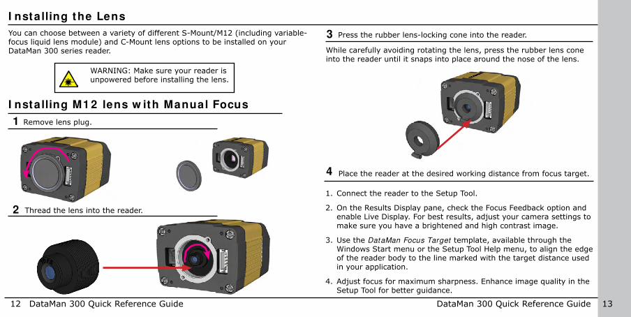
You can choose between a variety of different S-Mount/M12 (including variable-focus liquid lens module) and C-Mount lens options to be installed on your DataMan 300 series reader.
WARNING: Make sure your reader is unpowered before installing the lens.
2
3
4
1. Connect the reader to the Setup Tool.
2. On the Results Display pane, check the Focus Feedback option and enable Live Display. For best results, adjust your camera settings to make sure you have a brightened and high contrast image.
3. Use the DataMan Focus Target template, available through the Windows Start menu or the Setup Tool Help menu, to align the edge of the reader body to the line marked with the target distance used in your application.
4. Adjust focus for maximum sharpness. Enhance image quality in the Setup Tool for better guidance.
Press the rubber lens-locking cone into the reader.
While carefully avoiding rotating the lens, press the rubber lens cone into the reader until it snaps into place around the nose of the lens.
12 DataMan 300 Quick Reference Guide DataMan 300 Quick Reference Guide 13
I nstalling the Lens
Remove lens plug.1
I nstalling M1 2 lens w ith Manual Focus
Thread the lens into the reader.
Place the reader at the desired working distance from focus target.

After ixing the lens, verify focus position again, using the steps above.
Light connector
OR:
OR:
14 DataMan 300 Quick Reference Guide DataMan 300 Quick Reference Guide 15
5 Tighten the lens.
6 Attach front cover.
7 Insert and tighten screws.
I nstalling the Lens ( Cont inued)
Tighten in sequence. Torque limit: 9 Ncm (0.08 in-lbs).
Remove the protection ilm applied to the front cover before usage!
1
23
4PHILLIPS PAN HEAD M2 X 6MM

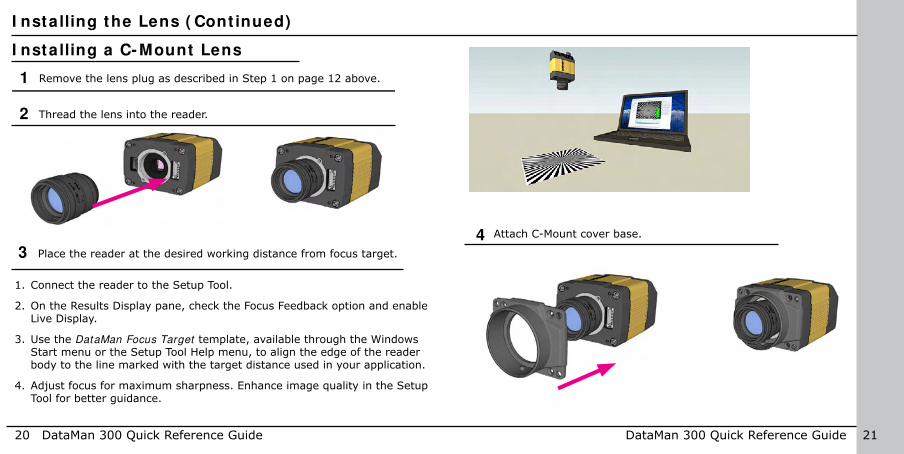
1 Remove the lens plug as described in Step 1 on page 12 above.
2
3
Snap the liquid lens module onto the nose of the lens, making sure that it lies lat.
Tighten the locking ring.
4 Connect the liquid lens cable to the reader.
Thread the lens into the reader.
16 DataMan 300 Quick Reference Guide DataMan 300 Quick Reference Guide 17
I nstalling a Liquid Lens
5
I nstalling the Lens ( Cont inued)

7
1. Connect the reader to the Setup Tool.
2. On the Results Display pane, check the Focus Feedback option and enable Live Display.
3. Use the DataMan Focus Target template, available through the Windows Start menu or the Setup Tool Help menu, to align the edge of the reader body to the line marked with the target distance used in your application.
4. Adjust focus for maximum sharpness. Enhance image quality in the Setup Tool for better guidance.
Place the reader at the desired working distance from focus target.Light connector
OR:
OR:
18 DataMan 300 Quick Reference Guide DataMan 300 Quick Reference Guide 19
1
23
4
Tighten in sequence. Torque limit: 9 Ncm (0.08 in-lbs).
Insert and tighten screws.6
I nstalling the Lens ( Cont inued)
Attach front cover.5
PHILLIPS PAN HEAD M2 X 6MM
1 Remove the lens plug as described in Step 1 on page 12 above.
20 DataMan 300 Quick Reference Guide DataMan 300 Quick Reference Guide 21
I nstalling the Lens ( Cont inued)
I nstalling a C- Mount Lens
2 Thread the lens into the reader.
3
1. Connect the reader to the Setup Tool.
2. On the Results Display pane, check the Focus Feedback option and enable Live Display.
3. Use the DataMan Focus Target template, available through the Windows Start menu or the Setup Tool Help menu, to align the edge of the reader body to the line marked with the target distance used in your application.
4. Adjust focus for maximum sharpness. Enhance image quality in the Setup Tool for better guidance.
Place the reader at the desired working distance from focus target.
Attach C-Mount cover base.4

NOTE
Do not unscrew the front-most part of the nose of the cover to avoid risking the glass lens falling out.
Align the peg on the reader and the slot on the cover so that the cover locks in place.
22 DataMan 300 Quick Reference Guide DataMan 300 Quick Reference Guide 23
1
23
4
I nstalling the Lens ( Cont inued)
Add screws to C-mount cover base.5 6 Attach front cover.
Tighten in sequence. Torque limit: 9 Ncm (0.8 in-lbs).PHILLIPS PAN HEAD M2 X 6MM

24 DataMan 300 Quick Reference Guide DataMan 300 Quick Reference Guide 25
I nstalling a Filter ( Old- Style Cover)
You can replace the window glass disk which is part of the light cover of your DataMan 300 reader with an optical ilter. Observe the following constraints on the ilter:
• Diameter (Ø)=12.5mm• Thickness (t): 1.8mm<t<2mm
Perform the following steps:
1. Insert a lat head screwdriver with a tip of max. 2.2 mm on either the top or bottom side of the ilter clip to release the clip on one side.
2. Insert the screw driver on the opposite side to fully release the clip, and remove the clip.
3. Remove clip and remove the glass disk.
4. Insert the ilter clip into the front window. Make sure that grooves in the clip are aligned with snap hooks in the front cover, and that the ilter is centered on sealing.
5. Press in the clip until you hear a clicking sound.

26 DataMan 300 Quick Reference Guide DataMan 300 Quick Reference Guide 27
Perform the following steps to install an optical ilter in the front cover.
Observe the following constraints on the ilter:
• Diameter (Ø): 12.3mm<Ø<12.7mm• Thickness (t): 1.6mm<t<2mm
1. First, remove the front cover: unscrew the four M3 screws and take off the LED cover.
2. Take off the rubber seal, remove the two smaller screws, and remove the PCB.
I nstalling a Filter ( Flat - Front Cover)
Use a T6 Torx screwdriver.
3. Working from the front of the PCB, press the legs of the ilter holder gently together and pull off the clip.
4. Insert irst the ilter glass, then the soft spacer (that was removed from its place between the ilter holder and the ilter retaining clip) into the ilter holder. A pair of tweezers may be helpful.
Filter retaining clip
LED PCBFilter holder
Soft spacerFilter glass
NOTE: Make sure that no electrostatic charges are applied to the PCB. (E.g. wear ESD shoes.)

28 DataMan 300 Quick Reference Guide DataMan 300 Quick Reference Guide 29
I nstalling a Filter ( Flat - Front Cover - Cont inued)
5. Snap it the ilter retaining clip onto the legs of the ilter holder. Ensure that the laser modules slide into the laser guides and the orientation pin its into the ilter retaining clip.
Check that the snap hooks are correctly positioned and fully engaged.
Laser guides
Orientation pin
Laser modules
6. Insert the PCB with the ilter retaining clip and the ilter holder back into the front cover. Ensure that the hole in the PCB meets the orientation pin in the front cover.
Fix the PCB with two Torx 6 screws of size 2.0x5 mm.
Use a torque of 8-10Ncm (11-14 oz-in).
Orientation pin
LED cover
Notch in PCB
PCB with ilter holder and ilter retaining clip

30 DataMan 300 Quick Reference Guide DataMan 300 Quick Reference Guide 31
7. Insert the rubber seal.
Note that the seal can only be installed in the correct orientation.
Tighten in sequence. Torque limit: 9 Ncm (0.08 in-lbs).
1
23
8. Remount the front cover. Observing the tightening sequence below, tighten all four screws to 9 Ncm using a torque wrench.
4
I nstalling a Filter ( Flat - Front Cover - Cont inued)
Left
Right
Rubber seal
Top
Bottom
LED cover side
Optics mount side
PHILLIPS PAN HEAD M2 X 6MM

• Using coaxial (DOAL) light • Using dark ield light
• Using ring light • Using spot light
32 DataMan 300 Quick Reference Guide DataMan 300 Quick Reference Guide 33
External Light Mount ing Brackets
You can mount your reader using external light mounting brackets. The brackets are intended to mount any of the different lights to the reader. They can also be used to mount the reader (with lights attached) to your machine. Pivot mounting, as illustrated, is optional. Perform the following steps:
1. Mount your reader on the camera plate and attach the screws.
2. Mount your reader with the camera plate attached to any of the external light bracket adapters.
Choose one of the following light options:

34 DataMan 300 Quick Reference Guide DataMan 300 Quick Reference Guide 35
Set t ing Focus
There is a range of reading distances available for different code sizes and focus positions. To set focus on your reader, use the following options depending on whether you use a liquid lens or a manual focus lens.
Liquid Lens Manual Focus Lens
Focus Feedback (Results Display) Focus Feedback (Results Display)
Optimize Focus (Focus Settings)
Focus Sweep (Focus Settings)
For setting Focus Sw eep, follow these guidelines:
• If your application has a consistent reading range, set the focus range to a limited depth of ield with no steps (for example, set it to 20) or with limited steps (for example, set it to 2 steps between 0 and 30). This way you can achieve fast performance.
• If your application has a variety of code types and sizes, set the focus range to a wider depth of ield with increased number of steps (for example, set it to 6 steps between 0 and 200). This way you can get better coverage.
Both Opt im ize Focus and the Focus Feedback use the same procedure for testing the current focus. They consider various subregions of the image.
For maximizing the performance of Optimize Focus and Focus Feedback, observe the following:
• Use a focus target (such as the one supplied with this Quick Reference Guide) that includes high-contrast features and is big enough that it ills at least a 100x100 pixel region in the center of the ield of view at the desired working distance.
• Make sure the target is perfectly lat (avoid loppy pieces of paper).• Make sure that the target is perfectly perpendicular to the optical axis
of the reader.• Make sure that the rest of the ield of view (such as the part not
covered by the focus target) does not contain any high-contrast features. For example, you would ideally ill the entire ield of view with a white card or sheet of paper (no shadows), then position the focus target in the middle.
• The supplied focus target (120x120mm) is appropriate for typical working distances. If you are using a working distance such that the

36 DataMan 300 Quick Reference Guide DataMan 300 Quick Reference Guide 37
target does not completely ill the image, make sure that there are no high-contrast features visible outside of the target (see previous bullet).
Set t ing Focus ( Cont inued)
Perform the following steps to use Focus Feedback :
1. Connect the reader to the Setup Tool.
2. On the Results Display pane, check the Focus Feedback option and enable Live Display.
3. The Focus Feedback column is displayed in colors ranging from red (bad focus) through yellow to green (sharp focus).
Position the reader in a way that the focus column becomes green. The maximum focus peak gets locked for better orientation. When the focus column is green, the lens is in focus and you will be able to decode the image.
For the C-mount (or other non-Cognex) S-Mount lenses, the lens’s focal length, focus setting, and aperture setting determine the ield of view and reading distance.
Field of View and Reading DistancesThe following maps show the ield of view of the DataMan 300 series readers. Reading distance values are also provided for 1-D and 2-D example code distances.Notes:
If you are using the focus feedback indicator to adjust a manual focus lens, you must apply power to the reader before you remove the cover. If you remove the cover before applying power, the internal illumination will not function.
If you are using a Liquid Lens, make sure that the cover is mounted and connected before you apply power. If you attach or remove the front cover while the reader is powered, the focus settings will be lost.

Reading Distance and Field of View ( DataMan 3 0 0 Series Readers w ith a 1 0 .3 m m Lens)
100mm
in
0
0 3
200 300
6 9 12
400 500 600
15 18 21
700 800
24 27
0
mm in
100
100
200
200
6
6
3
3
9
9
30 33
18.4 mm (0.72 in)
30 mm (1.18 in) 92.2 mm (3.6 in)
150 mm (5.9 in)
184.4 mm (7.2 in)
300 mm (11.8 in)243.4 mm (9.5 in)
396 mm (15.5 in)
5 mil 0-75 mm (2.9 in)
10 mil 0-210 mm (8.2 in)
20 mil 0-374 mm (14.7 in)
7 mil 0-215 mm (8.4 in)
13 mil 0-409 mm (16.1 in)
18 mil18 mil 0-500 mm (19.6 in)
5 mil 20-110 mm (0.7-4.3 in)
10 mil 15-325 mm (0.5-12.7 in)
20 mil 10-580 mm (22.8 in)
7 mil 20-350 mm (0.7-13.7 in)
13 mil 25-735 mm (0.9-28.9 in)
18 mil 25-840 mm (0.9-33.1 in)
2-D
1-D
DM300, DM302
DM300,
DM302
2-D
1-D
DM303
DM303
38 DataMan 300 Quick Reference Guide DataMan 300 Quick Reference Guide 39
This map shows the ield of view of the DataMan 300 series readers with a 10.3 mm lens (with or without a liquid lens).
The FOV values are shown as follows:
• outer: DM302, DM303• inner: DM300
The reading distances for the DM300 and DM302 readers are the same. DM303 features a higher resolution and more pixels in about the same sensor size. The following table shows the Field of View widths in mm at various distances.
distances in mm
DM300 DM302/DM303
50 18.4 30
100 36.8 60
150 55.3 90
250 92.2 150
500 184.4 300

Reading Distance and Field of View ( DataMan 3 0 0 Series Readers w ith a 1 6 m m Lens)
100mm
in
0
0 3
200 300
6 9 12
400 500 600
15 18 21 24
0
mm in
100
100
200
200
6
6
3
3
9
9
2-D2 mil 59-72 mm (2.3-2.8 in)
4 mil 55-207 mm (2.1-8.1 in)
8 mil 49-295 mm (1.9-11.6 in)
2 mil 60-125 mm (2.3-4.9 in)
4 mil 55-270 mm (2.1-10.6 in)
6 mil 56-400 mm (2.2-15.7 in)
5 mil 35-190 mm (1.3-7.4 in)
10 mil 30-420 mm (1.1-16.5 in)
20 mil 25-500 mm (0.9-19.6 in)
7 mil 45-400 mm (1.7-15.7 in)
13 mil 45-495 mm (1.7-19.4 in)
18 mil 45-540 mm (1.7-21.2 in)
40 mm (1.57 in)
25 mm (0.9 in)
100.8 mm (3.9 in)62.7 mm (2.4 in)
241.9 mm (9. 5 in) 150.5 mm (5.9 in)
1-D
DM300, DM302
DM300, DM302
2-D
1-D
DM303
DM303
40 DataMan 300 Quick Reference Guide DataMan 300 Quick Reference Guide 41
This map shows the ield of view of the DataMan 300 series readers with a 16 mm lens.
The FOV values are shown as follows:
• outer: DM302, DM303• inner: DM300
The reading distances for the DM300 and DM302 readers are the same. DM303 features a higher resolution and more pixels in about the same sensor size.
To make sure that your DM303 reader is able to decode at the minimum reading distances, use the reader in combination with the extension kit or without the front cover.
The following table shows the Field of View widths in mm at various distances.
distances in mm
DM300 DM302/DM303
50 12.5 20.1
100 25 40.3
150 37.6 60.4
250 62.7 100.8
500 125.4 201.6

100mm
in
0
0 3
200 300
6 9 12
400 500 600
15 18 21 24
0
mm in
100
100
200
200
6
6
3
3
9
9
2-D (2.4-3.8 in)
4 mil 58-167 mm (2.3-6.6 in)
8 mil 58-310 mm (2.3-12.2 in)
2 mil 59-173 mm (2.3-6.8 in)
4 mil 56-322 mm (2.2- 12.7 in)
6 mil 56-471 mm (2.2-18.5 in)
2 mil 61-109 mm (2.4-4.3 in)
4 mil 58-192 mm
8 mil 58-361 mm (2.3-14.2 in)
2 mil 59-199 mm (2.3-7.8 in)
4 mil 56-375 mm (2.2-14.8 in)
6 mil 56-551 mm (2.2-21.7 in)
34 mm (1.3 in)
22 mm (0.86 in)
52 mm (2.04 in)
33 mm (1.3 in)
172 mm (6.8 in)
111 mm (4.4 in)
1-D
DM300,
DM302
DM300,
DM302
2-D
1-D
DM303
DM303
86 mm (3.4 in)
56 mm (2.2 in)
(2.3-7.6 in)
2 mil 61-97 mm
42 DataMan 300 Quick Reference Guide DataMan 300 Quick Reference Guide 43
Reading Distance and Field of View ( DataMan 3 0 0 Series Readers w ith a 1 9 m m Liquid Lens)
This map shows the ield of view of the DataMan 300 series readers with a 19 mm liquid lens.
The FOV values are shown as follows:
• outer: DM302, DM303• inner: DM300
The reading distances for the DM300 and DM302 readers are the same. DM303 features a higher resolution and more pixels in about the same sensor size.
The following table shows the Field of View widths in mm at various distances.
distances in mm
DM300 DM302/DM303
50 11 17
100 22 34
150 33 52
250 56 86
500 111 172

Reading Distance and Field of View ( DataMan 3 0 0 Series Readers w ith a 2 5 m m Lens)
100mm
in
0
0 3
200 300
6 9 12
400 500 600
15 18 21 24
0
mm in
100
100
200
200
6
6
3
3
9
9
2 mil 100-155 mm (3.9-6.1 in)
4 mil 95-350 mm (3.7-13.7 in)
8 mil 90-470 mm (3.5-18.5 in)
2 mil 95-155 mm (3.7-6.1 in)
4 mil 92-350 mm (3.6-13.7 in)
6 mil 88-380 mm (3.4-14.9 in)
2 mil 95-155 mm (3.7-6.1 in)
4 mil 90-350 mm (3.5-13.7 in)
8 mil 88-385 mm (3.4-15.1 in)
2 mil 95-155 mm (3.7-6.1 in)
4 mil 92-360 mm (3.6-14.1 in)
6 mil 90-390 mm (3.5-21.2 in)
15.5 mm (0.6 in)
46 mm (1.8 in)
93.3 mm (3.6 in)
24.9 mm (0.9 in)74 mm (2.9 in)
149 mm (5.8 in)
2-D
1-D
DM300, DM302
DM300, DM302
2-D
1-D
DM303
DM303
44 DataMan 300 Quick Reference Guide DataMan 300 Quick Reference Guide 45
This map shows the ield of view of the DataMan 300 series readers with a 25 mm lens.
The FOV values are shown as follows:
• outer: DM302, DM303• inner: DM300
The reading distances for the DM300 and DM302 readers are the same. The DM303 features a higher resolution and more pixels in about the same sensor size.
The following table shows the Field of View widths in mm at various distances.
distances in mm
DM300 DM302/DM303
50 7.7 12.4
100 15.5 24.9
150 23.3 37.3
250 38.9 62.2
500 77.8 124.5
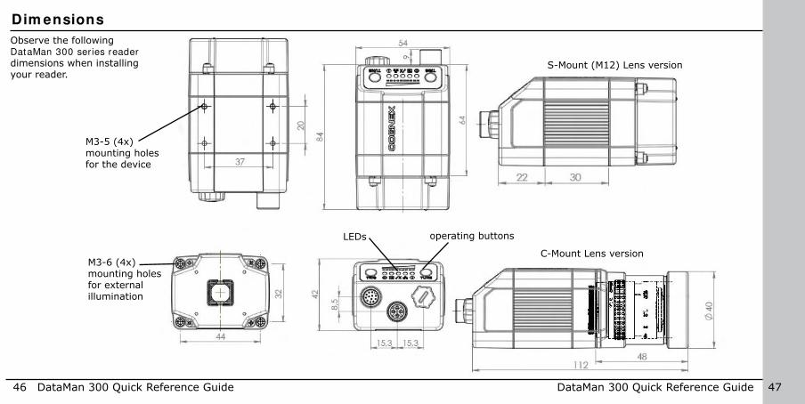
Observe the following DataMan 300 series reader
dimensions when installing your reader.
46 DataMan 300 Quick Reference Guide DataMan 300 Quick Reference Guide 47
Dim ensions
M3-5 (4x) mounting holes for the device
M3-6 (4x) mounting holes for external illumination
LEDs
S-Mount (M12) Lens version
operating buttons
C-Mount Lens version
Do not stare into beam when adding, removing, or changing cables. Cognex recommends to unpower the reader any time you make physical changes to it.
CONNECT YOUR READER
1. Connect the I/O+RS232+24V cable to your reader.
2. For a network connection, connect your reader, through an Ethernet cable, to your network.
3. Connect the cable to a 24V power supply.
48 DataMan 300 Quick Reference Guide DataMan 300 Quick Reference Guide 49
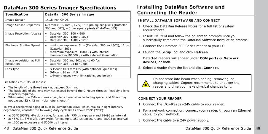
DataMan 300 Series Imager SpeciicationsSpeciication DataMan 3 0 0 Series I m ager
Image Sensor 1/1.8 inch CMOS
Image Sensor Properties 6.9 mm x 5.5 mm (H x V); 5.3 µm square pixels (DataMan 300 and 302), 4.5 µm square pixels (DataMan 303)
Image Resolution (pixels) • DataMan 300: 800 x 600• DataMan 302: 1280 x 1024• DataMan 303: 1600 x 1200
Electronic Shutter Speed • minimum exposure: 5 µs (DataMan 300 and 302), 12 µs (DataMan 303)
• maximum exposure: 1000 µs with internal illumination/100000 µs with external illumination
Image Acquisition at Full Resolution
• DataMan 300 and 302: up to 60 fps• DataMan 303: up to 40 fps
Lens Type • S-Mount 10.3 mm F:5 (with optional liquid lens)• S-Mount 16 mm F:9• C-Mount lenses (with limitations, see below)
Limitations to C-Mount lenses:
• The length of the thread may not exceed 5.4 mm.• The back side of the lens may not exceed beyond the C-Mount threads. Possibly a lens
spacer is required.• When using the C-Mount lens cover, lens dimensions including spacer and ilters may
not exceed 32 x 42 mm (diameter x length).
To avoid accelerated aging of built-in illumination LEDs, which results in light intensity degradation, consider the following duty cycle limits above 25°C (77°F):
• at 35°C (95°F): 4% duty cycle, for example, 750 µs exposure and 18493 µs interval• at 45°C (113°F): 2% duty cycle, for example, 350 µs exposure and 18093 µs interval
or 1000 µs exposure and 50000 µs interval
I nstalling DataMan Softw are and Connect ing the Reader
I NSTALL DATAMAN SOFTW ARE AND CONNECT
1. Check the DataMan Release Notes for a full list of system requirements.
2. Insert CD-ROM and follow the on-screen prompts until you successfully completed the DataMan Software installation process.
3. Connect the DataMan 300 Series reader to your PC.
4. Launch the Setup Tool and click Refresh.
Detected readers will appear under COM ports or Netw ork
devices, or both.
5. Select a reader from the list and click Connect .

IN1 but ton
Tune but ton
50 DataMan 300 Quick Reference Guide DataMan 300 Quick Reference Guide 51
Start the Setup Tool
Trigger but ton
Connect the reader to the Setup Tool to conigure it with the type of symbologies it will decode as well as other parameters, such as the type of trigger it will use and the format of the results it will generate.
Alternatively, conigure your reader by scanning the appropriate reader coniguration code from the Reader
Coniguration Codes document, available through the Windows Start menu or the Setup Tool Help menu.
Quick Setup
All main controls and visual feedback in a single view, for easiest setup and coniguration
Connect to Reader
Establish a connection to the reader
Results Display
View results
Light and I m ager Set t ings
Choose a trigger type and other acquisition parameters
System Set t ings
Conigure visual and audio feedback, trigger and output act ions
Table View
See all the selectable values in the Setup Tool in one table
Latest image
Read history
Context based help
Connection status
Region of interest
Code information

52 DataMan 300 Quick Reference Guide DataMan 300 Quick Reference Guide 53
Troubleshoot ing an Ethernet Connect ion
Based on your network coniguration, the Setup Tool may not be able to communicate with the reader and it will not appear in the list of Netw ork
devices.
First check your Ethernet connection with the reader and click Refresh in the Setup Tool. Next, scan the Enable DHCP code in the Reader Coniguration Codes document available from the Start menu. This might allow the reader to acquire a suitable IP address from a DHCP server on your subnet.
If the reader still does not appear, you can use either the Add Device or Force
Netw ork Set t ings options in the Setup Tool.
If you know the IP address of the reader, use the Add Device option. If you do not know the IP address, use the Force Netw ork Set t ings options. Either method should allow the DataMan 300 series reader to appear in the list of Netw ork devices so that you can connect to it through the Setup Tool and your Ethernet connection.
You can also use the RS-232 connection to conigure the reader with parameters that allow it to communicate over your Ethernet network.
Use the Setup Tool Menu Bar
The In1 button on the toolbar creates a virtual rising edge signal on Input 1. Use the In1 button to activate various actions such as training a code, optimizing brightness or setting a match string without a physical input 1 channel.
Each reader can store its current set of runtime parameters to a coniguration (.cfg) ile, which contains information such as the enabled symbologies and how any output data should be formatted.
The same coniguration ile can be loaded onto multiple readers, as the ile does not contain identiication information such as the IP address or device name of the reader used to create it.
A reader can also generate a Cognex device coniguration (.cdc) ile, which stores the set of runtime parameters plus any identiication data, such as the name of the device, its IP address, subnet mask, and so on. Cognex recommends generating a device coniguration ile for each reader to allow you to restore a reader to its operating state with minimal effort.
Use the File menu of the Setup Tool to manage .cfg and .cdc iles, export parameters, or to load, save, or train uploaded images.

54 DataMan 300 Quick Reference Guide DataMan 300 Quick Reference Guide 55
File Menu
Open Coniguration Open a saved .cfg coniguration ile.
Save Coniguration Create a .cfg coniguration ile of current runtime parameters.
Print Coniguration Code Generate a programming codes sheet representing your reader’s .cfg coniguration.
Restore Device Load a saved device coniguration .cdc ile, with run-time parameters plus device-speciic information for a particular DataMan 300 series reader.
Backup Device Create a device coniguration .cdc ile for a speciic reader.
Print Device Backup Code Generate a programming codes sheet representing your reader’s .cdc coniguration.
Export Parameters Save (all or only the non-default) parameters of your device in a text ile.
Load Image Load an 8-bit uncompressed grey-scale .bmp or .jpg image for analysis.
Save Image Save the latest acquired image with the .jpg or .bmp ile format.
Save Burst Images Save the latest batch of burst images.
Train Image Upload an image to be used for training.
Use the Setup Tool Menu Bar ( Cont inued)
Use the Edit menu for standard Cut, Copy and Paste operations.
Use the View menu to view reader information (serial number, irmware version, and so on) and to enable and disable various elements of the Setup Tool, and the Tasks menu to switch between various Setup Tool options.
Use the System menu to manage the current settings on the reader and to upgrade the features it currently supports:
System Menu
Save Settings Save the current parameters to non-volatile memory, which allows the reader to restore these settings each time you reboot it.
Reset Coniguration Reset all coniguration parameters in RAM (volatile memory) to the default settings.
Update Firmware Update the reader software.
Upload Feature Key Unlock additional features available in the reader software if you have the right key.
Show Device Log Error and exception conditions, such as missed triggers and trigger overruns are logged. The error LED signals unread error messages.
Delete Device Log Clear your device log.Use the Help menu to display Setup Tool version information.
Open Script... Open an example script.
Save Script... Save your script.

56 DataMan 300 Quick Reference Guide DataMan 300 Quick Reference Guide 57
I ndustr ia l ProtocolsThe DataMan 300 series readers support the following industrial protocols:
• EtherNet/IP™• PROFINET• MC Protocol• Modbus TCP
There are three ways to enable or disable Industrial Protocols. Using either method, a reboot is required for the changes to come into effect.
• Enable the protocols using the I ndustr ia l Protocols pane of the Setup Tool (under Communication Settings).
• Scan the appropriate Reader Coniguration codes (see Reader
Coniguration Codes available through the Windows Start menu or the Setup Tool Help menu).
• Send the appropriate DMCC (see Com m and Reference available through the Windows Start menu or the Setup Tool Help menu).
For more information on using the industrial protocols, read the DataMan
Communications and Programming Guide available through the Windows Start menu or the Setup Tool Help menu.
Select industrial protocol samples and tools you want to use when you install the DataMan Software.
Test ModeTest mode lets you conigure and test a reader that is connected to a production line without needing to slow down or stop your line. To enter Test mode,
• Press the button (to which you previously assigned this function) on the device for 3 seconds
• Send a DataMan Control Command (DMCC)• Click the Test Mode button in the Setup Tool
While in test mode, the reader by default ignores all external trigger sources and disables all input and output lines.
Check Autom at ic Tr iggering, and the reader will simulate external triggers at the interval that you specify. Click Accept Tr igger Batch, and the reader will accept and process a limited number of external triggers at production speed. In both cases, you can view images and decodes using production settings but at a slower rate and without sending output signals to your line.
For more information, see the Fixed Mount Reference.

58 DataMan 300 Quick Reference Guide DataMan 300 Quick Reference Guide 59
DataMan 3 0 0 Series Triggering
DataMan 300 series readers support the following trigger modes: • Self: At an interval you conigure, the reader automatically detects and
decodes codes in its ield of view. If you set a higher re-read delay than the trigger interval, there is a code output only once until the code is out of the ield of view for the duration of the re-read delay.
• Single (external trigger): Acquires a single image and attempts to decode any symbol it contains, or more than one symbol in cases where multicode is enabled. The reader relies on an external trigger source.
• Presentation: Scans, decodes and reports a single code in the ield of view. The reader relies on an internal timing mechanism to acquire images.
• Manual: Begins acquiring images when you press the trigger button on the reader, and continues acquiring images until a symbol is found and decoded or you release the button.
• Burst: Performs multiple image acquisitions based on an external trigger and decodes any symbol appearing in a single image or within a sequence of images, or multiple symbols in a single image or within a sequence of images when multicode is enabled. You can control the number of images within each burst and the interval between image acquisitions.
• Continuous: Begins acquiring images based on a single external trigger and continues to acquire and decode images until a symbol is found and decoded, or until multiple images containing as many codes as speciied in multicode mode are located, or until the trigger is released. You can conigure your reader to acquire images based on the start and stop signal from separate digital IO pulses.
External Tr iggers
If you are using external triggering you can use any of these methods to trigger your DataMan 300 series reader:
• Press the trigger button on the reader.
• Send a pulse on the I/O cable:
• Trigger + (red)
• Trigger - (black)
• Send a serial trigger command over the RS-232 connection or Ethernet connection.
• Press <CTRL>-T on the keyboard while the Setup Tool has the input focus.
• Click the Trigger button in the Setup Tool:

Mult i- Reader Tr iggering
For trigger modes other than Presentation, the DataMan 300 supports multi-reader triggering, also known as master-slave coniguration. In this coniguration, you conigure multiple DataMan readers as a group. Whenever any reader in the group is triggered, all the readers are triggered and the results from all the readers are assembled and transmitted by a single reader that you designate as the master.Multi-reader triggering is used to support extended ield of view reading and reading codes from multiple product surfaces:
To conigure multi-reader triggering, select the Master/ Slave pane in the Setup Tool (under System Set t ings). For more information, see the DataMan
Fixed Mount Readers Reference.
60 DataMan 300 Quick Reference Guide DataMan 300 Quick Reference Guide 61
DataMan 3 0 0 Series Read Setups
Your reader can be conigured for up to 16 different settings. In Single, Continuous, Self, and Burst trigger modes, you can enable multiple (or all) setups, and the DataMan 300 series
reader goes through all of the conigured imager combinations until there is a decoded image or there are no images left (that is, a no read image).You can change the parameters for the setups either on its dedicated pane, or in the Read
Setup pane’s appropriate table cell. Whatever you change on either pane is mirrored on the other.
It is possible to conigure a variety of acquisition parameters for your DataMan 300 series reader on a uniied Read Setups pane.
The currently selected setup also gets represented on other panes.
The read setup process starts with either a speciic setup, or the Last Successful Decode (as you choose).

By tuning, your DataMan 300 series reader automatically selects the best settings for the given reading situation, based on parameters of illumination, camera and decoder properties, and focal distance. Tuning autodisciminates all enabled symbologies (both 1-D and 2-D). If multiple symbols are found in the ield of view, tuning locks on the irst one found. Use this feature to create an optimum setting to read your codes.
You can use any of the following methods to tune your reader:
• Press the Tune button at least for 3 seconds on your reader. The irst press starts the tuning, and the second press cancels the tuning, if it is still ongoing.
• Turn on tuning in the Setup Tool.
• Start tuning by sending a DMCC, for more information, see the Com m and
Reference, available through the Windows Start menu or the Setup Tool Help menu.
• Use Input line 1 for tuning. Go to the Setup Tool’s System Set t ings pane and check Tune. You can also use the In1 button on the toolbar.
You can deine a stack of ilters to be applied to each image acquired by your DataMan 300 series reader. You can select the following ilters on the Setup Tool’s I m age Filter ing pane (under Light and Imager Settings):
• EqualizeThis ilter redistributes the brightness values of the pixels in the image. As a result, the range of brightness levels are more evenly represented. Use this ilter if you have too dark or too bright images.
• Stretch
This ilter linearly scales up or stretches the greyscale values in the input image to the full 256-step greyscale. The result is an output image with increased contrast.
• Low PassUsing this ilter results in output images where edges are smoothed or blurred.
• DilateThis ilter increases bright features and shrinks dark features. The result is an output image with larger areas of bright pixels. Use this ilter to remove dark specks.
• Erode
This ilter shrinks bright features and increases dark features. The result is an output image with larger areas of dark pixels. Use this ilter to remove light specks.
• Open
This ilter performs an erosion followed by a dilation to ilter out bright features that are smaller than the size of the processing neighborhood. The result is an output image with slightly decreased overall brightness.
62 DataMan 300 Quick Reference Guide DataMan 300 Quick Reference Guide 63
DataMan 3 0 0 Series Tuning DataMan 3 0 0 Series I m age Filter ing

• Close
This ilter performs a dilation followed by an erosion to ilter out dark features that are smaller than the size of the processing neighborhood. The result is an output image with slightly increased overall brightness.
• Auto St retch
This ilter reduces the pixel value range. It maps the pixel values from 0 to 255.
• Optical DensityThis ilter speciies an inversion of pixel values based on a logarithmic scale. The result is an output image that reveals the density of objects and features in the input image by measuring the amount of light that passes through them. Denser objects and features are represented by lighter pixels in the output image.
• InvertThis ilter speciies an inversion of pixel values based on the 256-step greyscale. The result is an output image that is a “negative” of the input image.
To use Image Filtering, perform the following steps:
1. On the Image Filtering pane, click Add.
2. Select a ilter from the Filter Propert ies drop-down box. You can add more than one ilter. You can also specify the order in which iltering is done by moving the ilters using the Up and Dow n buttons.
3. If the ilter you selected require further settings, change properties according to your needs.
4. Change the selection in the I m age to Use group box according to the symbology you want to be iltered (after making sure that that Symbology is enabled):
If no image is read, the Results Display shows the image according to your selection under No-Read Image.
64 DataMan 300 Quick Reference Guide DataMan 300 Quick Reference Guide 65
DataMan 3 0 0 Series I m age Filter ing ( Cont inued)

5. Go to the Displayed I m age Set t ings pane and change the Images to Use according to what you want to see on Live Display: the original or the iltered image.
6. You can compare the original and iltered results on the Results Display if
you choose the images from the Read Result History.
66 DataMan 300 Quick Reference Guide DataMan 300 Quick Reference Guide 67
The example images were taken using the Equalize ilter.
Training the Reader
Training your reader with the expected symbology can make the time required to decode successive symbols more consistent. In addition, training may help increase decode yield.
To train your reader, place a code in front of the reader and do one of the following:
• Press and hold the trigger button for a minimum of 3 seconds.
• Click and hold the trigger button in the Setup Tool for a minimum of 3 seconds.
• Click Train Code in the Results Display pane.
You can use training in Single, Burst, Continuous or Self trigger modes.
NOTE that only a single symbol of each symbology kind can be trained.
• Upload the code through File menu Train I m age.
DataMan 3 0 0 Series I m age Filter ing ( Cont inued)

68 DataMan 300 Quick Reference Guide DataMan 300 Quick Reference Guide 69
Training Feedback
The second LED from left on the reader glows green to indicate that it is currently trained, or yellow to indicate that it is not trained.
Connect the reader to the Setup Tool to untrain it and allow it to recognize other enabled symbologies.
I ncrem ental Training for Mult iple Sym bologies
If you want to train the reader to recognize multiple symbologies, you can present a single image showing all the desired symbologies and perform the training procedure previously described.
If you cannot present a single image showing all the necessary symbologies, you can enable incremental training on the Training tab of the Sym bology
Set t ings pane:
With incremental training enabled, you can train the reader using multiple images showing the symbologies you expect to decode. The reader will train each new symbology while retaining the existing trained symbologies.
Script ingTraining the Reader ( Cont inued)
In addition to standard formatting possibilities, you have the option to w rite a script inside the Setup Tool. On the Script - Based Form at t ing
tab, when script-based formatting is enabled, you can deine a JavaScript module to format data according to your needs. The FTP
Storage tab is for writing scripts to generate FTP ile names.
The script for data formatting not only allows you to have different data formatting combinations, but you can also perform operations on the output channel, for example, to pull output 1 up. You can conigure read results lexibly and conigure reader events before the result returns.
For the details of how to write the script and for scripting examples, please see the DataMan Communications and Programming Guide. You can ind scripting samples in the right-click context menu of the Scripting pane.
You can open your own scripts
through the Setup Tool’s File menu Open Script ... option.

1
2
3
4
5
70 DataMan 300 Quick Reference Guide DataMan 300 Quick Reference Guide 71
Package Detect ion Support
You can connect your package detection sensor to one of the digital inputs of your DataMan reader. When the reader receives a signal that a package is detected, images that the reader collected are not discarded at the end of the trigger. This way you can make sure that there was a package there, only the code was not readable. Looking at the No Read images will help you ind out why there was no decode results.
Package detection is only supported with Continuous trigger mode.
To make sure that the No Read images are collected, perform the following:
1. Connect your package detection device to one of the Inputs of your reader.
2. On the Setup Tool’s System Settings pane’s Inputs tab, check Allow
Buffered No- Read I m ages on the input you connected your reader to.
3. On the Setup Tool’s Image Record and Playback pane, change W hat
I m ages to Buffer to All, or No Read.
• In case of All, good reads are also saved together with No Reads.• In case of No Read the image is buffered if the reader fails to read.
For more information, see the DataMan Fixed Mount Readers Reference, available through the Windows Start menu or the Setup Tool Help menu.
External Light Control
A 4-pin cable is provided for the external light control.
Pin # Signal Nam e W ire Color
1 +24 VDC white
2 Brightness Control brown
3 GND black
4 Strobe blue
5 Chassis not connected
The above drawing shows the socket on the device.
Current load: average: 500mA, peak: 1A (max. 100µs).NOTE that this socket does not work if the external light is connected to one of the outputs on the I/O cable.

I / O Cable ( CCBL- 0 5 - 0 1 )
Pin # Signal Nam e W ire Color
1 Out 2 Yellow
2 TxD White/Yellow
3 RxD Brown
4 Out 3 White/Brown
5 In 1 Violet
6 Common In White/Violet
7 +24 VDC Red
8 GND Black
9 Common Out Green
10 In 0 Orange
11 Out 0 Blue
12 Out 1 Gray
The above drawing shows the plug on
the device.
10
12
1
9
8 7
6
5
114
3 2
10
12
1
9
8 7
6
5
114
3 2
72 DataMan 300 Quick Reference Guide DataMan 300 Quick Reference Guide 73
The I/O cable provides access to trigger and high-speed outputs. Unused wires can be clipped short or tied back using a tie made of non-conductive material. For RS-232, use the Power Supply return path for ground.
I / O Cable ( CCB- M1 2 xM1 2 Fy- xx)
Pin # Signal Nam e W ire Color
1 Out 2 White
2 TxD Green
3 RxD Pink
4 Out 3 Yellow
5 In 1 Grey
6 Common In Black
7 +24 VDC Brown
8 GND Blue
9 Common Out Purple
10 In 0 Red
11 Out 0 Grey/Pink
12 Out 1 Red/Blue
The I/O cable provides access to trigger and high-speed outputs. Unused wires can be clipped short or tied back using a tie made of non-conductive material.
For RS-232, use the Power Supply return path for ground.
The above drawing shows the plug on the device.
Controller Opto-isolators
10 Ω NPN Out
Out Common
PTCFuse
Controller Opto-isolators
10 Ω
Out Common
PNP OutPTC
Fuse
74 DataMan 300 Quick Reference Guide DataMan 300 Quick Reference Guide 75
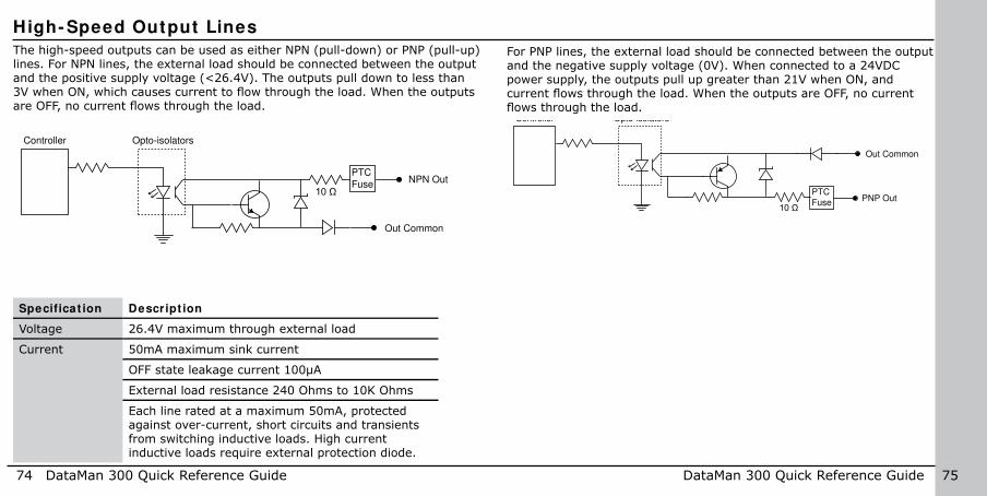
High- Speed Output Lines
The high-speed outputs can be used as either NPN (pull-down) or PNP (pull-up) lines. For NPN lines, the external load should be connected between the output and the positive supply voltage (<26.4V). The outputs pull down to less than 3V when ON, which causes current to low through the load. When the outputs are OFF, no current lows through the load.
Specificat ion Descript ion
Voltage 26.4V maximum through external load
Current 50mA maximum sink current
OFF state leakage current 100µA
External load resistance 240 Ohms to 10K Ohms
Each line rated at a maximum 50mA, protected against over-current, short circuits and transients from switching inductive loads. High current inductive loads require external protection diode.
For PNP lines, the external load should be connected between the output and the negative supply voltage (0V). When connected to a 24VDC power supply, the outputs pull up greater than 21V when ON, and current lows through the load. When the outputs are OFF, no current lows through the load.

76 DataMan 300 Quick Reference Guide DataMan 300 Quick Reference Guide 77
To connect to a PNP-compatible PLC input, connect Output 0, Output 1, Output 2 or Output 3 directly to the PLC input. When enabled, the output pulls the PLC input up to greater than 21V.
Common High Speed Out 0
PNP PLCPNP Compatible Input GND
24VDC
GND (pin 8)
24VDC (pin 7)
Common
Load
(Coil, Relay...)
Not to exceed 50mA
High Speed Out 0
To connect the high-speed outputs to a relay, LED or similar load, connect the negative side of the load to the output and the positive side to +24V. When the output switches on, the negative side of the load is pulled down to less than 3V, and 24 appears across the load. Use a protection diode for a large inductive load, with the anode connected to the output and the cathode connected to +24V.
GND (pin 8)
24VDC (pin 7)
High Speed Output W ir ing
To connect to an NPN-compatible PLC input, connect Output 0, Output 1, Output 2, or Output 3 directly to the PLC input. When enabled, the output pulls the PLC input down to less than 3V.
GND (pin 8)
24VDC (pin 7)
Common High Speed Out 0
NPN PLC
NPN Compatible Input GND
24VDC

Input 0
2.74K
Common In
2.74K
1.0K
+3.3V
10K
78 DataMan 300 Quick Reference Guide DataMan 300 Quick Reference Guide 79
Acquisit ion Triggering
The acquisition trigger input on the reader is opto-isolated. To trigger from an NPN (pull-down) type photo-detector or PLC output, connect Com m on I n to +24V and connect I n 0 to the output of the detector. When the output turns on, it pulls I n 0 down to 0V, turning the opto-coupler on.
To trigger from an PNP (pull-up) photo-detector or PLC output, connect I n 0 to the output of the detector and connect Com m on I n to 0V. When the output turns on, it pulls I n 0 up to 24V, turning the opto-coupler ON.
26.4V Max. across input pins - Transition approximately 12V (Min.)
Ethernet M1 2 to RJ4 5 CableThe Ethernet cable provides Ethernet connection for network communications. The Ethernet cable can be connected to a single device or provide connections to multiple devices via a network switch or router.
Note: Cables are sold separately. The wiring for this cable follows standard industrial Ethernet M12 speciications. This differs from the 568B standard.
P1 Pin# Signal Nam e W ire Color P2 Pin#
6 TPO+ White/Orange 1
4 TPO- Orange 2
5 TPI+ White/Green 3
7 TRMA Blue 4
1 TRMB White/Blue 5
8 TPI- Green 6
2 TRMC White/Brown 7
3 TRMD Brown 8
80 DataMan 300 Quick Reference Guide DataMan 300 Quick Reference Guide 81
DataMan 300 series readers meet or exceed the requirements of all applicable standards organizations for safe operation. However, as with any electrical equipment, the best way to ensure safe operation is to operate them according to the agency guidelines that follow. Please read these guidelines carefully before using your device.
Regula-
tor
Speciication
USA FCC Part 15, Class AFDA/CDRH Laser Notice No 50
Canada ICES-003European Commu-nity
EN55022:2006 +A1:2007, Class AEN55024:1998 +A1:2001 +A2: 2003EN60950EN60825-1
Australia C-TICK, AS/NZS CISPR 22 / EN 55022 for Class A EquipmentJapan J55022, Class A
FCC Class A Com pliance Statem ent
This equipment has been tested and found to comply with the limits for a Class A digital device, pursuant to Part 15 of the FCC rules. These lim-its are designed to provide reasonable protection against harmful inter-ference when the equipment is operated in a commercial environment. This equipment generates, uses, and can radiate radio frequency energy and, if not installed and used in accordance with the instructions, may cause harmful interference to radio communications. Operation of this
Com pliance Statem ents
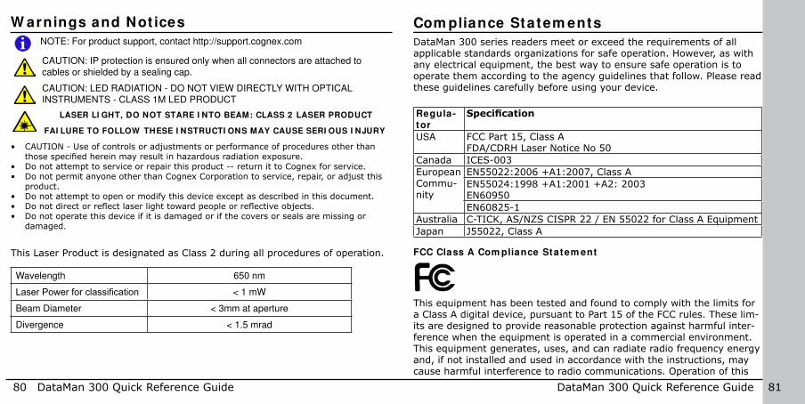
i NOTE: For product support, contact http://support.cognex.com
CAUTION: IP protection is ensured only when all connectors are attached to
cables or shielded by a sealing cap.
W arnings and Not ices
LASER LI GHT, DO NOT STARE I NTO BEAM: CLASS 2 LASER PRODUCT
FAI LURE TO FOLLOW THESE I NSTRUCTI ONS MAY CAUSE SERI OUS I NJURY
• CAUTION - Use of controls or adjustments or performance of procedures other than those speciied herein may result in hazardous radiation exposure.
• Do not attempt to service or repair this product -- return it to Cognex for service. • Do not permit anyone other than Cognex Corporation to service, repair, or adjust this
product. • Do not attempt to open or modify this device except as described in this document.• Do not direct or relect laser light toward people or relective objects. • Do not operate this device if it is damaged or if the covers or seals are missing or
damaged.
This Laser Product is designated as Class 2 during all procedures of operation.
Wavelength 650 nm
Laser Power for classiication < 1 mW
Beam Diameter < 3mm at aperture
Divergence < 1.5 mrad
CAUTION: LED RADIATION - DO NOT VIEW DIRECTLY WITH OPTICAL
INSTRUMENTS - CLASS 1M LED PRODUCT

82 DataMan 300 Quick Reference Guide DataMan 300 Quick Reference Guide 83
Laser Safety Statem ent
Compliance with FDA performance standards for laser products except for deviations pursuant to Laser Notice No. 50, dated June 24, 2007.
This device has been tested in accordance with IEC60825-1 2nd ed., and has been certiied to be under the limits of a Class 2 Laser device.
Use of controls or adjustments or performance of procedures other than those speciied herein may result in hazardous radiation exposure.
UL and cUL Statem ent
UL and cUL listed: UL60950-1 2nd ed. and CSA C22.2 No.60950-1 2nd ed.
For European Com m unity Users
Cognex complies with Directive 2002/96/EC OF THE EUROPEAN PARLIA-MENT AND OF THE COUNCIL of 27 January 2003 on waste electrical and electronic equipment (WEEE).
Com pliance Statem ents ( Cont inued)equipment in a residential area is likely to cause harmful interference, in which case the user will be required to correct the interference at personal expense.
Canadian Com pliance
This Class A digital apparatus complies with Canadian ICES-003.Cet appareil numérique de la classe A est conforme à la norme NMB-003 du Canada.
C- Tick Statem ent
Conforms to AS/NZS CISPR 22/ EN 55022 for Class A Equipment.
European Com pliance
The CE mark on the product indicates that the system has been tested to and conforms to the provisions noted within the 2004/108/EEC Electromagnetic Compatibility Directive and the 2006/95/EEC Low Voltage Directive.
For further information please contact: Cognex Corporation One Vision Drive Natick, MA 01760 USA
Cognex Corporation shall not be liable for use of our product with equipment (i.e., power supplies, personal computers, etc.) that is not CE marked and does not comply with the Low Voltage Directive.

84 DataMan 300 Quick Reference Guide DataMan 300 Quick Reference Guide 85
Weight 165 g
Operating Temperature 0ºC — 45ºC (32ºF — 113ºF)
Storage Temperature -10ºC — 60ºC (-14ºF — 140ºF)
Maximum Humidity 95% (non-condensing)
Environmental IP65 (with cable or protection cap attached to all connectors, front cover properly installed)
Vibration EN61373 including IEC 60068-2-6,60068-2-64 6.4, and 60068-2-27
RS-232 RxD, TxD according to TIA/EIA-232-F
Codes Data Mat r ixTM (IDMax: ECC 0, 50, 80, 100, 140, and 200; IDQuick: ECC200)QR Code and microQR Code, MaxiCode, Aztec Code
UPC/EAN/JANCodabar, Interleaved 2 of 5, Code 39, Code 128, and Code 93, Pharma,
Postal, RSS/CS, PDF 417, MicroPDF 417, MSI
Discrete I/O operating limits
HS Output0,1
IMAX @ 24 VDC 50 mARMAX @ 12 VDC 150 Ω @ 24 VDC 470 Ω
Input 0 (Trigger)Input 1
VIH ±12 — ±28 VVIL 0 — ±8 VITYP @ 12 VDC 2.0 mA @ 24 VDC 4.2 mA
Power Supply Requirements
24V +/- 10% Maximum current: 250 mA (internal illumination) 850 mA (internal + external lights) Maximum power: 5W (internal illumination) 18W (internal + external lights)
Light Connector Current load Average: 500mAPeak: 1A (max. 100µs)
Ethernet Speed 10/100
Duplex Mode Full duplex or half duplex
DataMan 300 Series Speciications This product has required the extraction and use of natural resources for its production. It may contain hazardous substances that could impact health and the environment, if not properly disposed.
In order to avoid the dissemination of those substances in our environment and to diminish the pressure on the natural resources, we encourage you to use the appropriate take-back systems for product disposal. Those systems will reuse or recycle most of the materials of the product you are disposing in a sound way.
The crossed out wheeled bin symbol informs you that the product should not be disposed of along with municipal waste and invites you to use the appropri-ate separate take-back systems for product disposal.
If you need more information on the collection, reuse, and recycling systems, please contact your local or regional waste administration.
You may also contact your supplier for more information on the environmental performance of this product.
Com pliance Statem ents ( Cont inued)

Copyright © 2013 Cognex Corporation All Rights Reserved. This document may not be
copied in whole or in part, nor transferred to any other media or language, without the written permission of Cognex Corporation. The hardware and portions of the software described in this document may be covered by one or more of the U.S. patents listed
on the Cognex web site http://www.cognex.com/patents.asp. Other U.S. and foreign
patents are pending. Cognex, the Cognex logo, and DataMan are trademarks, or registered trademarks, of Cognex Corporation.
P/ N 590-7168 rev B
Reader Program m ing Codes
Reset Scanner to
Factory Defaults Reboot Scanner