Embed Size (px)
Citation preview

PRIMERGY
DataCenter Rack
Heidenbluth/FierleyFujitsu Siemens Computers GmbH cognitas PS81730 Muniche-mail: Internet:[email protected].: (089) 61001-157Fax: (++49) 700 / 372 00000U41145-J-Z146-1-74Sprachen: En
Edition March 2001
Comments… Suggestions… Corrections…The User Documentation Department would like to knowyour opinion on this manual. Your feedback helps us tooptimize our documentation to suit your individual needs.
Fax forms for sending us your comments are included atthe back of the manual.
There you will also find the addresses of the relevant UserDocumentation Department
Copyright and Trademarks
Copyright © 2001 Fujitsu Siemens Computers GmbH.
All rights reserved.Delivery subject to availability; right of technical modifications reserved.
All hardware and software names used are trademarks of their respective manufacturers.
This manual was produced bycognitas. Gesellschaft für Technik-Dokumentation mbHwww.cognitas.de
This manual is printed onpaper treated withchlorine-free bleach.

German
English


Contents1 Introduction . . . . . . . . . . . . . . . . . . . . . . . . . . . . 11.1 The DataCenter Rack . . . . . . . . . . . . . . . . . . . . . . . 11.2 Target group . . . . . . . . . . . . . . . . . . . . . . . . . . . . 21.3 Summary of contents . . . . . . . . . . . . . . . . . . . . . . . 31.4 Notational conventions . . . . . . . . . . . . . . . . . . . . . . . 31.5 User-friendly documentation – verified quality . . . . . . . . . . . 41.6 Technical data . . . . . . . . . . . . . . . . . . . . . . . . . . . 5
2 Important notes . . . . . . . . . . . . . . . . . . . . . . . . . . 72.1 Rack philosophy . . . . . . . . . . . . . . . . . . . . . . . . . . 72.2 Notes on safety . . . . . . . . . . . . . . . . . . . . . . . . . . 92.3 Notes on mounting the rack components . . . . . . . . . . . . 102.4 Environmental protection . . . . . . . . . . . . . . . . . . . . 11
3 Preparations . . . . . . . . . . . . . . . . . . . . . . . . . . 133.1 Unpacking and checking the delivery unit . . . . . . . . . . . . 133.2 Opening the DataCenter Rack . . . . . . . . . . . . . . . . . . 153.3 The height unit . . . . . . . . . . . . . . . . . . . . . . . . . . 163.4 Inserting cage and spring nuts . . . . . . . . . . . . . . . . . 173.5 The system architect . . . . . . . . . . . . . . . . . . . . . . . 193.6 Installation procedure . . . . . . . . . . . . . . . . . . . . . . 20
4 Setting up the DataCenter Rack . . . . . . . . . . . . . . . . 214.1 Mounting the anti-tilt bracket . . . . . . . . . . . . . . . . . . . 224.2 Setting up an add-on rack . . . . . . . . . . . . . . . . . . . . 23
5 Mounting rack components . . . . . . . . . . . . . . . . . . 255.1 Mounting in the front 19-inch area . . . . . . . . . . . . . . . . 265.2 Mounting in the expansion area . . . . . . . . . . . . . . . . . 285.2.1 Mounting the frame holder . . . . . . . . . . . . . . . . . . . . 285.2.2 Mounting rack components . . . . . . . . . . . . . . . . . . . 295.3 Mounting in the rear 19-inch area . . . . . . . . . . . . . . . . 30
6 Cable management . . . . . . . . . . . . . . . . . . . . . . . 316.1 Mounting components of the cable management . . . . . . . . 316.1.1 Articulated cable guides . . . . . . . . . . . . . . . . . . . . . 326.1.2 Cable guide with cable clips . . . . . . . . . . . . . . . . . . . 336.2 Connecting and disconnecting cables . . . . . . . . . . . . . . 346.2.1 Connecting cables . . . . . . . . . . . . . . . . . . . . . . . . 346.2.2 Disconnecting cables . . . . . . . . . . . . . . . . . . . . . . 34
U41145-J-Z146-1-74
Contents
6.3 Routing cables . . . . . . . . . . . . . . . . . . . . . . . . . . 356.3.1 Articulated cable guide . . . . . . . . . . . . . . . . . . . . . . 356.3.2 Cable routing and strain relief for the built-in rack component . . 366.3.3 Cable guide with cable clips . . . . . . . . . . . . . . . . . . . 396.3.4 Direct connection . . . . . . . . . . . . . . . . . . . . . . . . . 40
7 Power supply . . . . . . . . . . . . . . . . . . . . . . . . . . 417.1 Connecting to the mains using 1-phase socket strip . . . . . . . 417.2 Connecting to the mains using 3-phase socket strip . . . . . . . 427.3 Power distribution . . . . . . . . . . . . . . . . . . . . . . . . . 437.4 Power supply via UPS . . . . . . . . . . . . . . . . . . . . . . 447.5 Connecting to the potential compensating system . . . . . . . . 45
Related publications . . . . . . . . . . . . . . . . . . . . . . . . . . . . 47
Index . . . . . . . . . . . . . . . . . . . . . . . . . . . . . . . . . . . . 49
U41145-J-Z146-1-74

1 Introduction
1.1 The DataCenter Rack
The DataCenter Rack is a cabinet for system components of the PRIMERGYserver series of Fujitsu Siemens Computers using space-saving 19-inchtechnology. Offering high expansion capabilitiy within a small area, theDataCenter Rack provides a compact and flexible platform for creating complexconfigurations.
Figure 1: The DataCenter Rack variants
24 HU 38 HU 46 HU
U41145-J-Z146-1-74 1
2
Target group Introduction
The 3more
The lacce
The 3normThe r
For thallow2 HU
Dum
1.2
Thisensutechn
The mwithointeg3-phaautho
The mservitraine
8 HU and 46 HU DataCenter Rack can be extended easily using one oradd-on racks.
ockable doors and side panels provide security against unauthorizedss and manipulation.
8 HU DataCenter Rack is dimensioned so that it will pass through aal, 2 m high door in an upright position, complete with its transport palette.ack can accommodate devices with a total of 38 height units.
e three rack variants there is the option of vertical mounting frames whichadditional installation of one device with 2 HU and/or three devices witheach and a installation depth of 300 mm.
my covers are available for closing off empty height units.
Target group
manual is intended for those responsible for installing the hardware andring that the system runs smoothly (service personnel, technicians andical specialists).
anual is designed so that you can put the DataCenter Rack into operationut previous special knowledge. Knowledge of the hardware to berated is helpful for understanding the various connection options. These power connection is an exception and must only be installed by anrized electrician.
anual does not include technical descriptions of services which only thece department of Fujitsu Siemens Computers GmbH or appropriatelyd specialist staff are allowed to carry out.
U41145-J-Z146-1-74

Introduction Summary of contents
and
its,
tatathis
1.3 Summary of contents
This manual describes how to set up the DataCenter Rack, how to connectroute the cables, and provides an introduction to the philosophy behind theDataCenter Rack.
The installation of components such as the server and storage expansion unfor example, are described in the manuals for those devices.
Further information is provided
� in the “Security, Guarantee and Ergonomics” manual
� in the documentation for the individual components installed in the rack
� in the documentation for the operating systems used
1.4 Notational conventions
bold type Used for emphasis in the body of the text
“quotation marks” Used for references to other chapters, sections ormanuals
Ê Identifies an action that you need to take
I Alerts you to important information, notes and tips
V CAUTION! Warning sign indicating that your health, the correcfunctioning of your system or the security of your dmay be at risk if you ignore the information given atpoint.
U41145-J-Z146-1-74 3
4
User-friendly documentation – verified quality Introduction
1.5
As paeditoaudit
Thisaspe
– G– U– O– S
st– E– L– C– A
The cTÜVtekom
User-friendly documentation – verifiedquality
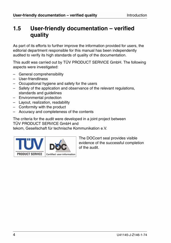
rt of its efforts to further improve the information provided for users, therial department responsible for this manual has been independentlyed to verify its high standards of quality of the documentation.
audit was carried out by TÜV PRODUCT SERVICE GmbH. The followingcts were investigated:
eneral comprehensibilityser-friendlinessccupational hygiene and safety for the usersafety of the application and observance of the relevant regulations,andards and guidelinesnvironmental protectionayout, realization, readabilityonformity with the productccuracy and completeness of the contents
riteria for the audit were developed in a joint project betweenPRODUCT SERVICE GmbH and, Gesellschaft für technische Kommunikation e.V.
The DOCcert seal provides visibleevidence of the successful completionof the audit.
U41145-J-Z146-1-74
U41145-J-Z146-1-74 5
Introduction Technical data
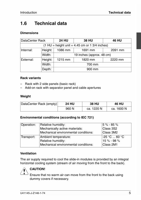
1.6 Technical data
Dimensions
Rack variants
– Rack with 2 side panels (basic rack)– Add-on rack with separator panel and cable apertures
Weight
Environmental conditions (according to IEC 721)
Ventilation
The air supply required to cool the slide-in modules is provided by an integralhorizontal cooling system (stream of air moving from the front to the back).
V CAUTION!
Ensure that no warm air can move from the front to the back usingdummy covers if necessary.
DataCenter Rack 24 HU 38 HU 46 HU
(1 HU = height unit = 4.45 cm or 1 3/4 inches)
Internal: Height: 1086 mm 1691 mm 2091 mm
Width: 19 inches (approx. 48 cm)
External: Height: 1215 mm 1820 mm 2220 mm
Width: 700 mm
Depth: 900 mm
DataCenter Rack (empty) 24 HU 38 HU 46 HU
960 N ca. 1220 N ca. 1600 N
Operation: Relative humidity:Mechanically active materials:Mechanical environmental conditions:
5 % - 85 %Class 3S2Class 3M2
Transport: Ambient temperature:Relative humidity:Mechanical environmental conditions:
-25 °C ... 60 °C15 % - 98 %Class 2M1
Technical data Introduction
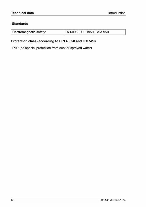
Standards
Protection class (according to DIN 40050 and IEC 529)
Electromagnetic safety: EN 60950, UL 1950, CSA 950
IP00 (no special protection from dust or sprayed water)
6 U41145-J-Z146-1-74
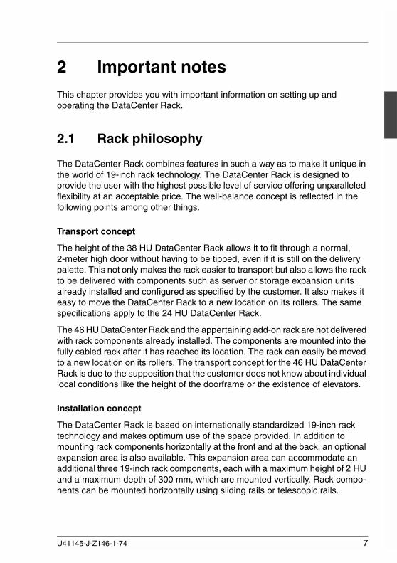
2 Important notesThis chapter provides you with important information on setting up andoperating the DataCenter Rack.
2.1 Rack philosophy
The DataCenter Rack combines features in such a way as to make it unique inthe world of 19-inch rack technology. The DataCenter Rack is designed toprovide the user with the highest possible level of service offering unparalleledflexibility at an acceptable price. The well-balance concept is reflected in thefollowing points among other things.
Transport concept
The height of the 38 HU DataCenter Rack allows it to fit through a normal,2-meter high door without having to be tipped, even if it is still on the deliverypalette. This not only makes the rack easier to transport but also allows the rackto be delivered with components such as server or storage expansion unitsalready installed and configured as specified by the customer. It also makes iteasy to move the DataCenter Rack to a new location on its rollers. The samespecifications apply to the 24 HU DataCenter Rack.
The 46 HU DataCenter Rack and the appertaining add-on rack are not deliveredwith rack components already installed. The components are mounted into thefully cabled rack after it has reached its location. The rack can easily be movedto a new location on its rollers. The transport concept for the 46 HU DataCenterRack is due to the supposition that the customer does not know about individuallocal conditions like the height of the doorframe or the existence of elevators.
Installation concept
The DataCenter Rack is based on internationally standardized 19-inch racktechnology and makes optimum use of the space provided. In addition tomounting rack components horizontally at the front and at the back, an optionalexpansion area is also available. This expansion area can accommodate anadditional three 19-inch rack components, each with a maximum height of 2 HUand a maximum depth of 300 mm, which are mounted vertically. Rack compo-nents can be mounted horizontally using sliding rails or telescopic rails.
U41145-J-Z146-1-74 7

Rack philosophy Important notes
Mounting components using telescopic rails and the corresponding cablemanagement system allows maintenance and repair work to be carried outmore easily and cost-effectively and supports hot-replace solutions.
Cable management
The DataCenter Rack provides an efficient cable management system.Because the cables are routed along the side of the rack components usingarticulated cable guides or cable guides with cable clips, the connection side ofthe components remains tidy and making it is easy to see where each cableleads. A distinction is made between two types of connection: a connection viaan articulated cable guide and a direct connection.
An articulated cable guide is used together with rack components that aremounted in the DataCenter Rack using telescopic rails. This combination allowsrack components to be pulled from the rack without having to disconnect thecables first and therefore allows boards to be replaced during operation in hot-replace solutions.
If rack components are mounted on sliding rails, cables are connected directly.This means that the cables can be short but does not allow for hot-replacesolutions.
Excess lengths of cable can be fastened at certain locations within theDataCenter Rack using one or more cable guides with cable clips.
Ventilation concept
If the DataCenter Rack is to function reliably, adequate ventilation of all the rackcomponents must be provided. To ensure that this is always the case, the venti-lation concept applied to all PRIMERGY rack components has been coordi-nated with the DataCenter Rack to provide a uniform overall solution. The basicventilation concept is designed so that fresh air is drawn in through the front andwarm air is expelled from the back. In addition to the air vents at the front andthe back of the DataCenter Rack, the rack has no floor, which increases aircirculation.
The ventilation concept of PRIMERGY rack components has been coordinatedbetween the components themselves and with the DataCenter Rack. However,although this holds true for PRIMERGY rack components, it does not neces-sarily hold true for rack components from other manufacturers. Therefore,before you install a rack component from a different manufacturer in the rack,check whether it matches the above-mentioned ventilation concept. Otherwise,damage may occur.
8 U41145-J-Z146-1-74
Important notes Notes on safety
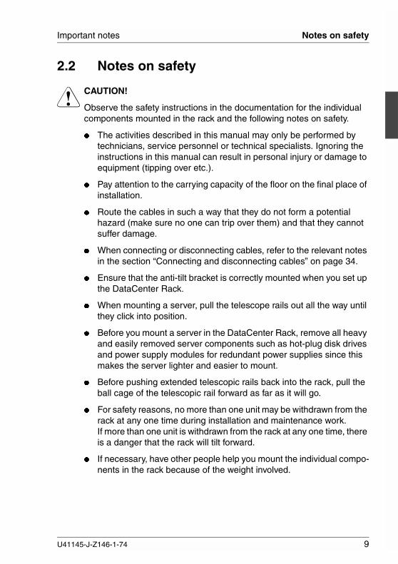
2.2 Notes on safety
V CAUTION!
Observe the safety instructions in the documentation for the individualcomponents mounted in the rack and the following notes on safety.
� The activities described in this manual may only be performed bytechnicians, service personnel or technical specialists. Ignoring theinstructions in this manual can result in personal injury or damage toequipment (tipping over etc.).
� Pay attention to the carrying capacity of the floor on the final place ofinstallation.
� Route the cables in such a way that they do not form a potentialhazard (make sure no one can trip over them) and that they cannotsuffer damage.
� When connecting or disconnecting cables, refer to the relevant notesin the section “Connecting and disconnecting cables” on page 34.
� Ensure that the anti-tilt bracket is correctly mounted when you set upthe DataCenter Rack.
� When mounting a server, pull the telescope rails out all the way untilthey click into position.
� Before you mount a server in the DataCenter Rack, remove all heavyand easily removed server components such as hot-plug disk drivesand power supply modules for redundant power supplies since thismakes the server lighter and easier to mount.
� Before pushing extended telescopic rails back into the rack, pull theball cage of the telescopic rail forward as far as it will go.
� For safety reasons, no more than one unit may be withdrawn from therack at any one time during installation and maintenance work.If more than one unit is withdrawn from the rack at any one time, thereis a danger that the rack will tilt forward.
� If necessary, have other people help you mount the individual compo-nents in the rack because of the weight involved.
U41145-J-Z146-1-74 9
Notes on mounting the rack components Important notes
V CAUTION!
� Install only system expansions that satisfy the requirements and rulesgoverning safety and electromagnetic compatibility and relating totelecommunications terminal equipment. If you install other expan-sions, you may damage the system or violate the safety regulationsand regulations governing RFI suppression. Information can beobtained from customer service or your sales office.
� If you cause a defect on the device by installing or exchanging systemexpansions, the warranty is invalidated.
� The configurations available in the DataCenter Rack can carry aleakage current >3.5 mA. Therefore, a ground connection must beestablished before connecting to the mains (see chapter “Powersupply” on page 41).
� The power connection of the DataCenter Rack must be installed byan authorized electrician.
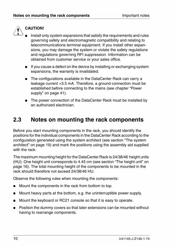
2.3 Notes on mounting the rack components
Before you start mounting components in the rack, you should identify thepositions for the individual components in the DataCenter Rack according to theconfiguration generated using the system architect (see section “The systemarchitect” on page 19) and mark the positions using the assembly aid suppliedwith the rack.
The maximum mounting height for the DataCenter Rack is 24/38/46 height units(HU). One height unit corresponds to 4.45 cm (see section “The height unit” onpage 16). The total mounting height of the components to be mounted in therack should therefore not exceed 24/38/46 HU.
Observe the following rules when mounting the components:
� Mount the components in the rack from bottom to top.
� Mount heavy parts at the bottom, e.g. the uninterruptible power supply.
� Mount the keyboard or RC21 console so that it is easy to operate.
� Position the dummy covers so that later extensions can be mounted withouthaving to rearrange components.
10 U41145-J-Z146-1-74

Important notes Environmental protection
� To accommodate the ventilation concept and ensure proper ventilation of allthe components in the rack, any unused areas must be closed using dummycovers.
� Mark and mount the unit in accordance with the technical manual andassembly aid supplied with the rack.
2.4 Environmental protection
Environmentally friendly product design and development
This product has been designed in accordance with the FSC standard for“environmentally friendly product design and development”.
This means that the designers have taken into account crucial criteria such asdurability, selection of materials and coding, emissions, packaging, the easewith which the product can be dismantled and the extent to which it can berecycled.
This saves resources and thus reduces the harm done to the environment.
Notes on saving energy
Devices that do not have to be on permanently should not be switched on untilthey are needed and should be switched off during long breaks and when workis finished.
Notes on packaging
We recommend that you do not throw away the original packaging in case youneed it later for transportation. If possible, devices should be transported in theiroriginal packaging.
Notes on dealing with consumables
Please dispose of printer consumables and batteries in accordance with localregulations.
Notes on labeling plastic housing parts
Please avoid attaching your own labels to plastic housing parts whereverpossible, since this makes it difficult to recycle them.
U41145-J-Z146-1-74 11

Environmental protection Important notes
Take-back, recycling and disposal
For details on take-back and reuse of devices and consumables within Europe,contact your FSC branch office/subsidiary or our recycling center in Paderborn:
Fujitsu Siemens Computers GmbHRecycling CenterD-33106 Paderborn
Tel. ++49 5251 8180-10
Fax ++49 5251 8180-15
Further information on environmental protection
The Fujitsu Siemens Computers GmbH representative for environmentalprotection will be happy to answer any further questions you may haveconcerning environmental protection.
Fujitsu Siemens Computers GmbHEnvironmental ProtectionWerner-von-Siemens-Straße 6D-86159 Augsburg
Tel. ++49 821 599-2999
Fax ++49 821 599-3440
12 U41145-J-Z146-1-74
3 PreparationsThis chapter describes the preparations for installation and all the tasksinvolved in setting up and operating the DataCenter Rack.
3.1 Unpacking and checking the delivery unit
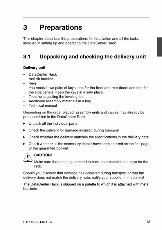
Delivery unit
– DataCenter Rack– Anti-tilt bracket– Keys
You receive two pairs of keys, one for the front and rear doors and one forthe side panels. Keep the keys in a safe place.
– Tools for adjusting the leveling feet– Additional assembly materials in a bag– Technical manual
Depending on the order placed, assembly units and cables may already bepreassembled in the DataCenter Rack.
Ê Unpack all the individual parts.
Ê Check the delivery for damage incurred during transport.
Ê Check whether the delivery matches the specifications in the delivery note.
Ê Check whether all the necessary details have been entered on the first pageof the guarantee booklet.
V CAUTION!
Make sure that the bag attached to back door contains the keys for therack.
Should you discover that damage has occurred during transport or that thedelivery does not match the delivery note, notify your supplier immediately!
The DataCenter Rack is shipped on a palette to which it is attached with metalbrackets.
U41145-J-Z146-1-74 13

Unpacking and checking the delivery unit Preparations
The palette has an integrated ramp function that allows you to remove theDataCenter Rack from the palette without any additional aids.
V CAUTION!
Pay attention to the carrying capacity of the floor on the final place ofinstallation!
Ê First of all, remove the metal brackets attached to the four leveling feet.
Figure 2: Removing the rack from the transport palette
Ê Reassemble the palette to create a ramp (1) - (4).
V CAUTION!
If necessary, ask other people for help.
Ê Use the open-ended wrench supplied to retract the leveling feet (5). TheDataCenter Rack is now standing on four rollers.
Ê Roll the DataCenter Rack from the palette and push it to its final position (6).Please note that the DataCenter Rack can weigh up to 360 kg.
14 U41145-J-Z146-1-74

Preparations Opening the DataCenter Rack
3.2 Opening the DataCenter Rack
The doors can only be opened using a key or the optional chipcard reader.
Opening the door with a key
Figure 3: Opening the DataCenter Rack
Ê Turn the key clockwise (1).The door handle pivots forward (2).
Ê Turn the door handle about 90 degrees anticlockwise (3).
Opening the door with a chipcard
The chipcard reader is located to the right of the door handle in the spacebetween the metal door and the piece of glass and is marked with a chipcardsymbol.
Ê Insert a valid chipcard into the chipcard reader.
U41145-J-Z146-1-74 15
The height unit Preparations
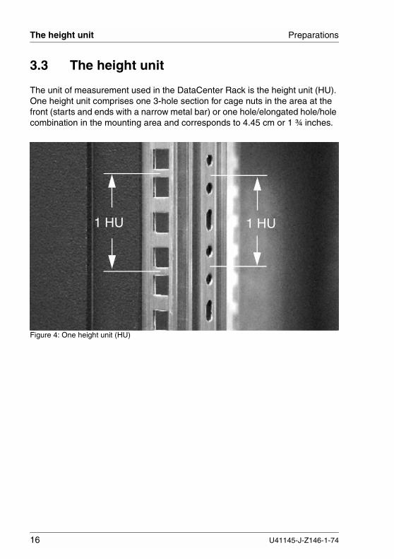
3.3 The height unit
The unit of measurement used in the DataCenter Rack is the height unit (HU).One height unit comprises one 3-hole section for cage nuts in the area at thefront (starts and ends with a narrow metal bar) or one hole/elongated hole/holecombination in the mounting area and corresponds to 4.45 cm or 1 ¾ inches.
Figure 4: One height unit (HU)
1 HU1 HU
16 U41145-J-Z146-1-74
Preparations Inserting cage and spring nuts
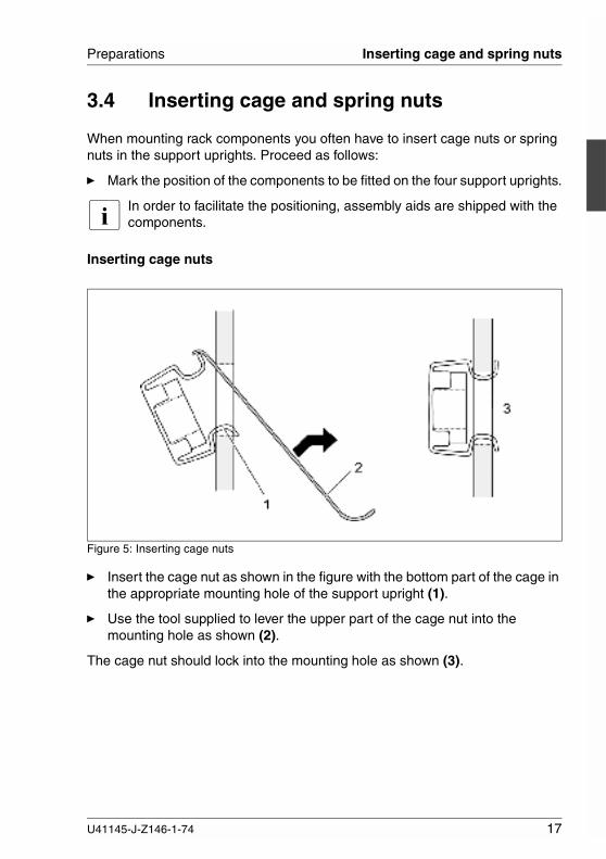
3.4 Inserting cage and spring nuts
When mounting rack components you often have to insert cage nuts or springnuts in the support uprights. Proceed as follows:
Ê Mark the position of the components to be fitted on the four support uprights.
I In order to facilitate the positioning, assembly aids are shipped with thecomponents.
Inserting cage nuts
Figure 5: Inserting cage nuts
Ê Insert the cage nut as shown in the figure with the bottom part of the cage inthe appropriate mounting hole of the support upright (1).
Ê Use the tool supplied to lever the upper part of the cage nut into themounting hole as shown (2).
The cage nut should lock into the mounting hole as shown (3).
U41145-J-Z146-1-74 17

Inserting cage and spring nuts Preparations
Inserting spring nuts
Figure 6: Inserting spring nuts
Ê Insert the spring nut into the appropriate groove of the support upright at themarked location (1) - (4).
Ê If necessary, slide the spring nut within the groove until it locks in the correctposition (5).
18 U41145-J-Z146-1-74

Preparations The system architect
3.5 The system architect
The system architect configuration tool is used as an aid for configuring theDataCenter Rack.
Before you start mounting components in the DataCenter Rack, you shouldidentify the positions for the individual components in the DataCenter Rackaccording to the configuration generated using the system architect and, ifavailable, the assembly aid supplied with the rack.
The maximum mounting height for the DataCenter Rack is 24/38/46 heightunits. One height unit corresponds to 4.45 cm. The total mounting height of thecomponents to be mounted in the DataCenter Rack must not exceed24/38/46 HU.
Figure 7: Configuration example
3 x PRIMERGY N200
dummy cover 1HU PRIMERGY S30console switch
PRIMERGY S30
PRIMERGY N400
PRIMERGY N400
rack consoleconsole switchconsole switch
PRIMERGY N800/4HDD
dummy cover 2HU PRIMERGY N800/4HDD
UPS APCUPS APC
U41145-J-Z146-1-74 19
Installation procedure Preparations
3.6 Installation procedure
V CAUTION!
Observe the safety and installation notes in the chapter “Important notes”on page 7.
Perform the steps in the installation procedure in the specified order. Theindividual steps are described in detail in the following chapters.
� Setting up the DataCenter Rack (adjust using spirit level)
V CAUTION!
Pay attention to the carrying capacity of the floor on the final place ofinstallation!
� Mounting the anti-tilt bracket
� Mounting the rack components
� Mounting the components for the cable management system andconnecting and routing the cables
� Connecting to the power supply
20 U41145-J-Z146-1-74

4 Setting up the DataCenter RackThis chapter describes how to mount the anti-tilt bracket on the DataCenterRack and set up add-on racks.
V CAUTION!
Pay attention to the carrying capacity of the floor on the final place ofinstallation!
Ê Roll the DataCenter Rack to its final position.
Figure 8: Adjusting the DataCenter Rack
Ê Adjust the rack horizontally by unscrewing the four leveling feet (1) at thefront and the back of the base using the tool supplied. Make sure the rollersno longer have contact with the floor.
11
U41145-J-Z146-1-74 21

Mounting the anti-tilt bracket Setting up the DataCenter Rack
4.1 Mounting the anti-tilt bracket
Figure 9: Mounting the anti-tilt bracket 1
Ê Push the anti-tilt bracket under the rack from the front.
V CAUTION!
The anti-tilt bracket must make firm contact with the ground and will befastened on the rear of the rack.
Figure 10: Mounting the anti-tilt bracket 2
Ê Attach the anti-tilt bracket left and right on the rear of the rack by fasteningthe screws (1).
1
22 U41145-J-Z146-1-74

Setting up the DataCenter Rack Setting up an add-on rack
4.2 Setting up an add-on rack
A picture illustrating how to set up the add-on rack is included in the package.The steps for mounting and setting up the add-on rack are described bellow.
V CAUTION!
Pay attention to the carrying capacity of the floor on the final place ofinstallation!
Ê Set up the basic rack as described earlier in this chapter.
Ê Remove the side panel from the basic rack to which you want to attach theadd-on rack.
Ê Mount the add-on connectors to the basic rack and add-on rack.
Ê Mount the add-on separator panel. Pay attention to the mounting tab on theseparator panel. The panel should be assembled with the cable aperture tothe back.
Ê Place the add-on rack next to the basic rack and align the two racks byadjusting the leveling feet.
Ê Screw the two racks together with the add-on connectors.
Ê Mount the side panel you removed earlier to the add-on rack.
U41145-J-Z146-1-74 23

5 Mounting rack componentsThis chapter describes how to prepare the DataCenter Rack for the installationof rack components. Refer to the appropriate operating manuals for informationon how to mount the components themselves.
The rack has three areas in which components can be mounted:
– the 19-inch area with 24/38/46 HU, which is accessible from the front and isused for mounting the rack components horizontally.
– the optional expansion area with 1 x 2 HU resp. 3 x 2 HU, which is acces-sible from the front and is used for vertically mounting up to 6 rack compo-nents, each with a maximum depth of 300 mm.
– the 19-inch area that is accessible from the back and which is used formounting components horizontally mounting if not already occupied by othercomponents.
Before you prepare the DataCenter Rack and start mounting components, youshould use the system architect to help you determine the mounting positionand the mounting height. Also observe the information in the section “Notes onmounting the rack components” on page 10.
V CAUTION!
Pay attention to the carrying capacity of the floor on the final place ofinstallation!
U41145-J-Z146-1-74 25

Mounting in the front 19-inch area Mounting rack components
5.1 Mounting in the front 19-inch area
Components are mounted in the front 19-inch area of the DataCenter Rackusing either telescopic or sliding rails. Light components can also be mountedwith the front panel.
If components are mounted using telescopic rails, all the cables leading to thecomponents are routed via an articulated cable guide. If maintenance workneeds to be performed, the cables can remain connected when the componentsare withdrawn from the DataCenter Rack. This makes maintenance mucheasier and also allows boards in hot-replace slots to be replaced duringoperation.
If components are mounted using sliding rails, all the cables are routed directlyto the components and are connected without any special aids, i.e. withoutusing an articulated cable guide. If maintenance work needs to be performed,all connected cables must be disconnected before the components can bewithdrawn from the DataCenter Rack.
A support bracket is required for mounting components regardless of whethertelescopic rails or sliding rails are used.
Figure 11: Support brackets with a load capacity of 50 kg and 150 kg respectively
Support brackets with a load capacity of 50 kg (1 HU) and 150 kg (2 HU) areavailable. A cable clip can be mounted on each support bracket for verticalcable routing.
26 U41145-J-Z146-1-74

Mounting rack components Mounting in the front 19-inch area
Mounting the support bracket
The support bracket is mounted on the rear left support upright at the appro-priate height and is used to fasten the left sliding or telescopic rail at the back.The support bracket is mounted level with the lower edge of the PRIMERGYserver. The PRIMERGY N70 server is an exception: in this case, the supportbracket is mounted level with the upper edge of the server.
Figure 12: Mounting a support bracket with a load capacity of 150 kg (2 HU)
Ê Mount the support bracket as shown and screw it to the rear left supportupright at the appropriate height using one or two screws and cage nuts,depending on which variant you are mounting.
Ê If necessary, you can mount one additional cable clip to each supportbracket for vertical cable routing.
U41145-J-Z146-1-74 27

Mounting in the expansion area Mounting rack components
5.2 Mounting in the expansion area
Three to six 19-inch rack components with a maximum of 2 HU each can bemounted vertically in the optional expansion area of the DataCenter Rack to theleft of the 19-inch area. The depth of the components cannot exceed 300 mm.Gaps that occur when you mount 1 HU components must be covered. Compo-nents are mounted using their front panel only.
5.2.1 Mounting the frame holder
The frame holder for the optional expansion area can be mounted in the rack ata later time.
Figure 13: Removing the cover
Ê Remove the left side panel.
Ê Remove the two screws fastening the cover to the support upright (1).
Ê Remove the four screws on the front of the cover (2) and remove the coverfrom the expansion area.
Ê Mount the frame holder for the expansion area in reverse order.
1 2
28 U41145-J-Z146-1-74

Mounting rack components Mounting in the expansion area
5.2.2 Mounting rack components
Figure 14: Mounting a rack component in the expansion area
Ê Remove the cover from the appropriate slot (1).
Ê Insert the cage nuts as required for the component to be installed (2).
Ê Install the rack component (3) and cover any resulting gap with an appro-priate cover.
1
2
3
U41145-J-Z146-1-74 29
Mounting in the rear 19-inch area Mounting rack components
5.3 Mounting in the rear 19-inch area
In the rear 19-inch area, you can mount additional rack components if:
– the front area is either unoccupied with rack components
– the rack components mounted in the front area leave enough space foradditional components to be mounted at the back (in the rear area)
An appropriate support bracket is required for mounting rack components onthe lefthand side. If you cannot use an existing bracket, you will have to mounta new support bracket at the appropriate position.
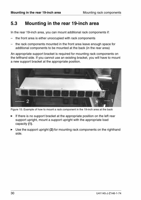
Figure 15: Example of how to mount a rack component in the 19-inch area at the back
Ê If there is no support bracket at the appropriate position on the left rearsupport upright, mount a support upright with the appropriate loadcapacity (1).
Ê Use the support upright (2) for mounting rack components on the righthandside.
12
30 U41145-J-Z146-1-74

6 Cable managementThis chapter describes how to mount the components of the cable managementsystem and how to connect cables and route them in the DataCenter Rack.
1. Mounting components of the cable management system2. Connecting cables3. Routing cables
6.1 Mounting components of the cablemanagement
The cable management system comprises the following parts:
– articulated cable guides
– cable guides with cable clips
– cable guides
– support bracket with raster for cable guides
The cable guides can be used in a flexible manner. Depending on what isneeded, an articulated cable guide can be changed into a cable guide with cableclips or vice versa. If necessary, small devices can be mounted onto an emptycable guide. The cable tray includes a grid to attach cage nuts.
U41145-J-Z146-1-74 31

Mounting components of the cable management Cable management
6.1.1 Articulated cable guides
Articulated cable guides are used for rack components that are mounted in therack using telescopic rails.
The mounting height of the articulated cable guide depends on the rackcomponent to be installed and must not interfere with the telescopic rails.
Figure 16: Mounting an articulated cable guide
Ê Insert the articulated cable guide into the support upright for the cable guideat the appropriate height as shown (1).
Ê Fasten the articulated cable guide to the rear support upright using a springnut and a screw (2).
1 2
32 U41145-J-Z146-1-74
Cable management Mounting components of the cable management
6.1.2 Cable guide with cable clips
You can use one or more cable guides with cable clips to store excess lengthsof cable in an orderly fashion at appropriate locations in the rack.
The other cable clips supplied can be distributed over the support brackets asneeded.
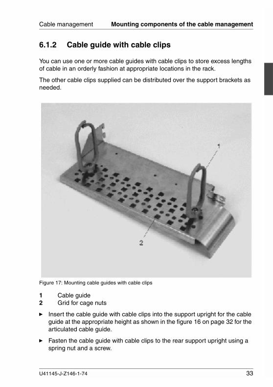
Figure 17: Mounting cable guides with cable clips
1 Cable guide2 Grid for cage nuts
Ê Insert the cable guide with cable clips into the support upright for the cableguide at the appropriate height as shown in the figure 16 on page 32 for thearticulated cable guide.
Ê Fasten the cable guide with cable clips to the rear support upright using aspring nut and a screw.
U41145-J-Z146-1-74 33
Connecting and disconnecting cables Cable management
6.2 Connecting and disconnecting cables
V CAUTION!
The power plug must be pulled out!Read the documentation for the device before you connect it.Never connect or disconnect cables during thunderstorms.When disconnecting a cable, always grasp the plug. Never pull on thecable.Connect or disconnect cables in the sequence shown below.
6.2.1 Connecting cables
Ê Switch off all affected devices.
Ê The power plug of all affected devices must be pulled out of the socket stripin the DataCenter Rack.
Ê Attach all cables to the devices. Mark the cables and note what functioneach cable serves. Above all, observe the safety notes in the chapter“Important notes”.
Ê Plug all data transmission cables into the sockets provided for the datatransmission or telephone networks.
Ê Plug the mains power plugs of all devices into the sockets of the socketstrip(s) in the rack. Make sure that the power cables of the devices areplugged in so that an even distribution of power to the three phases (L1, L2,L3) is achieved (see chapter “Power supply” on page 41).
6.2.2 Disconnecting cables
Ê Switch off all affected devices.
Ê Pull the power plugs of all affected devices out of the sockets on the socketstrip in the DataCenter Rack.
Ê Pull all data transmission cables out of the sockets provided for the datatransmission or telephone networks.
Ê Disconnect all cables on the devices.
34 U41145-J-Z146-1-74
Cable management Routing cables
6.3 Routing cables
This section contains several examples of how to route cables in the DataCenterRack.
6.3.1 Articulated cable guide
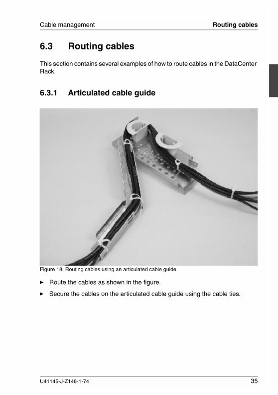
Figure 18: Routing cables using an articulated cable guide
Ê Route the cables as shown in the figure.
Ê Secure the cables on the articulated cable guide using the cable ties.
U41145-J-Z146-1-74 35
Routing cables Cable management
6.3.2 Cable routing and strain relief for the built-in rackcomponent
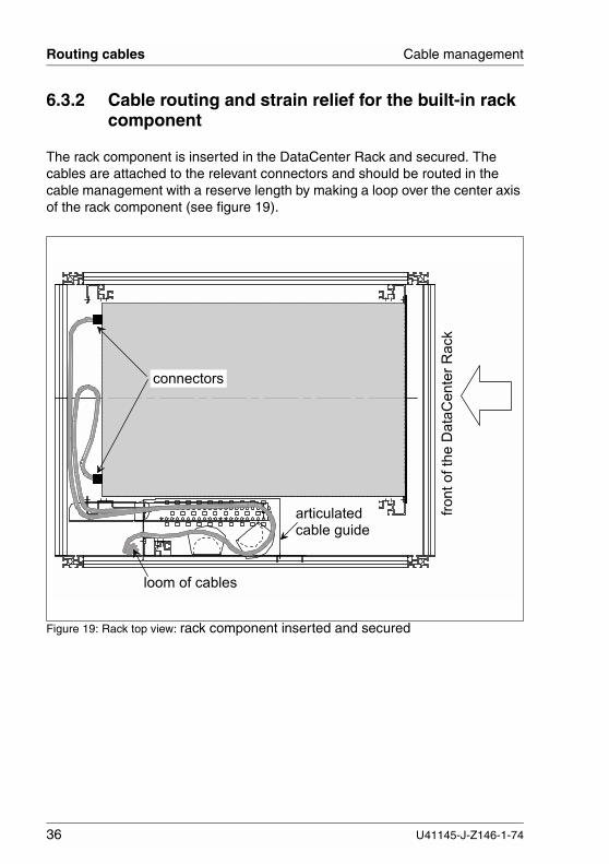
The rack component is inserted in the DataCenter Rack and secured. Thecables are attached to the relevant connectors and should be routed in thecable management with a reserve length by making a loop over the center axisof the rack component (see figure 19).
Figure 19: Rack top view: rack component inserted and secured
�������������
��������� ��
� � � � � � � �
� � � � � � � � � � � � � � � � � �
� � � � � � � � � � � �
36 U41145-J-Z146-1-74
Cable management Routing cables
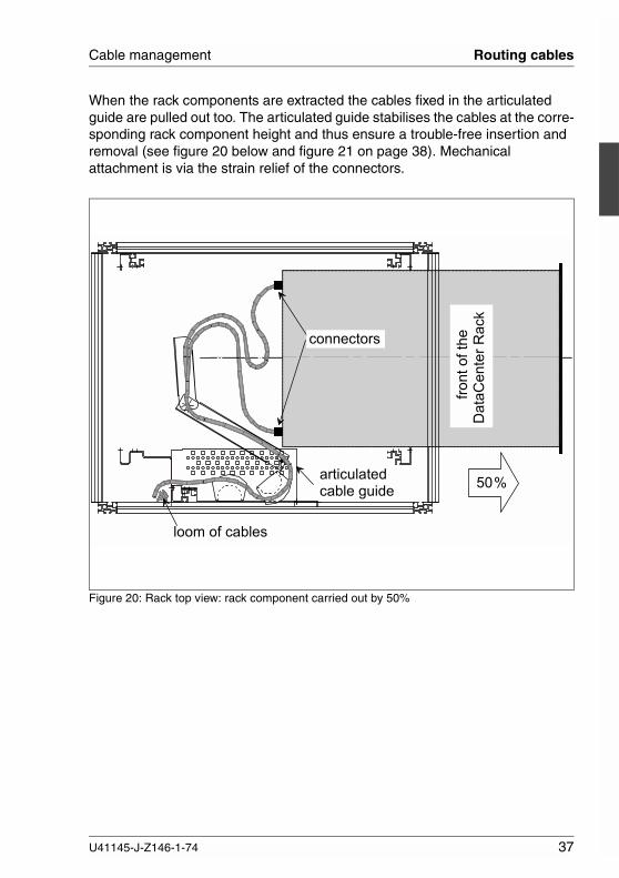
When the rack components are extracted the cables fixed in the articulatedguide are pulled out too. The articulated guide stabilises the cables at the corre-sponding rack component height and thus ensure a trouble-free insertion andremoval (see figure 20 below and figure 21 on page 38). Mechanicalattachment is via the strain relief of the connectors.
Figure 20: Rack top view: rack component carried out by 50%
� � � � � � � � � � � � � � � � � � � � � �
� � � � � � � � � � � �
� � � � � � � �
�������������������
��������� ��
U41145-J-Z146-1-74 37

Routing cables Cable management
Figure 21: Rack top view: rack component carried out by 100%
���� �
����������������
��������� �
���� ����
��� ������
���������
�������� ����
38 U41145-J-Z146-1-74

Cable management Routing cables
6.3.3 Cable guide with cable clips
The example below shows you how to route excess lengths of cable in theDataCenter Rack using a cable guide with cable clips. Please note that in thecase of fiber optic cables, a certain bending radius must not be exceeded.
Figure 22: Routing cables using a cable guide with cable clips
Ê Route the cables as shown in the figure.
U41145-J-Z146-1-74 39
Routing cables Cable management
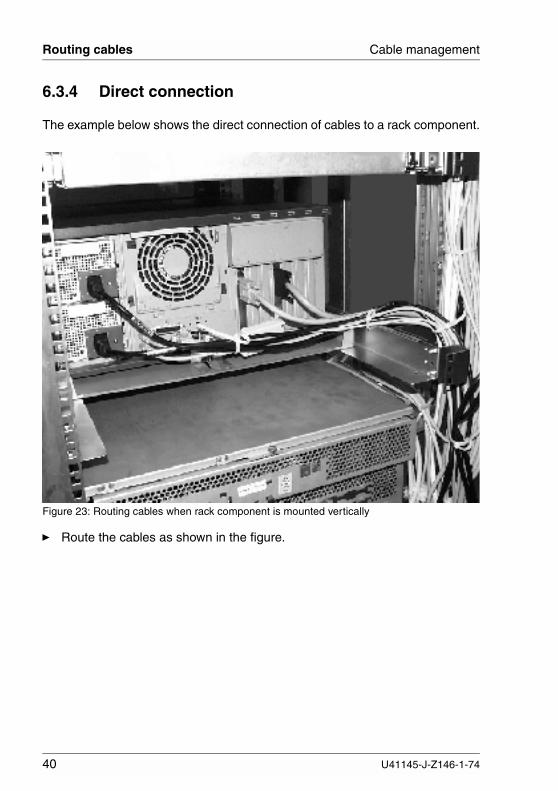
6.3.4 Direct connection
The example below shows the direct connection of cables to a rack component.
Figure 23: Routing cables when rack component is mounted vertically
Ê Route the cables as shown in the figure.
40 U41145-J-Z146-1-74
7 Power supplyThere are circumstances under which the power supply of the DataCenter Rackis a component of a redundancy concept. The DataCenter Rack conceptnormally provides a 3-phase ac mains connection and thus offers a uniformpower distribution on the supply network.
Servers with redundant power supply units can then be connected to differentphases and are thus given additional phase redundancy for high availabilityconfigurations. If a phase fails, the systems which are connected to anotherphase remain operational.
By using a number of 3-phase mains connections it is even possible to createredundancy of the supply systems. This option is becoming increasinglyimportant with regard to the server farms aspect.
The power supply complies with the requirements of the EN60950 regulations.This allows a DataCenter Rack to be connected with a flexible (5-wire) cable of5 x 1.5 mm2 up to a rated current up to 16 A per phase for example.
If the DataCenter Rack is connected to the mains by a 1- or 3-phase socketstrip, the configuration can carry leakage currents >3.5 mA. In this case, theconnection of the DataCenter Rack to the inhouse supply network must beperformed using a rigid connection or an IEC309-compliant connector.
7.1 Connecting to the mains using 1-phasesocket strip
For a 1-phase mains connection, a socket strip is available, with ten insulatedsockets (10 A), a power cord with a length of 5 m, and an IEC309-compliantconnector (see figure 25 on page 43).
Ê Screw the socket strip to the left rear support upright of the DataCenterRack.
Power is supplied to the individual rack components within the DataCenter Rackvia the socket strip.
U41145-J-Z146-1-74 41

Connecting to the mains using 3-phase socket strip Power supply
7.2 Connecting to the mains using 3-phasesocket strip
For a 3-phase mains connection, a socket strip with 3 x 5 sockets is available(see figure 25 on page 43). The three phases are divided in the socket stripbetween one protective contact socket (16 A) and four insulated sockets (10 A)per phase.
Depending on the device configuration, the socket strip can be connected to theinhouse supply network via a power cord with a length of 7 m using a rigidconnection or an IEC309-compliant connector.
A 5-pole terminal strip for connecting the five leads (L1, L2, L3, N and PE) isavailable and is located on the socket strip of the rack.
V CAUTION!
The connection must be made by an authorized electrician only.The power connection cable must be voltage free.
Figure 24: Mains power connection
Ê Route the external 5-pole connection cable into the rack (1).
Ê Connect the external 5-pole connection cable to the 5-pole terminal strip (2)of the socket strip in DataCenter Rack.
42 U41145-J-Z146-1-74

Power supply Power distribution
7.3 Power distribution
Power is supplied to the individual rack components within the DataCenter Rackvia the socket strip.
If the number of sockets available on the socket strip is not enough, you can usea supplementary socket strip as an extension.
Figure 25: Configuration examples
The following supplementary socket strips are available:
� socket strip with 5 sockets (one 16 A protective contact socket and four 10 Ainsulated sockets) and 3 m connection cable with protective contact utilityconnector.
� socket strip with 3 sockets (three 10 A protective contact sockets) and1.5 m connection cable with insulated connector (max. 10 A).
Ê If necessary, screw additional socket strips to the (left or right) rear supportupright of the DataCenter Rack. Only one supplementary socket strip perphase is permitted.
Ê Connect the socket strips as shown.
� � � � � � � � � � � � �
� � � � � � �� � � � � � � � �
�� � � �
� � � �
� � �
� �
� �
� �
� �
� � � � � � �� � � � � � � � �
� � � � � �� � � � � � � � �
U41145-J-Z146-1-74 43

Power supply via UPS Power supply
7.4 Power supply via UPS
When uninterruptible power supply (UPS) units are involved in supplying energyto the rack and its components there are many possible combinations:
� The rack is supplied completely via the UPS:
In this case the UPS should be connected directly to the mains. In the rackthe systems are connected directly or optionally via a 3-way socket strip tothe UPS.
� The rack is partly supplied via a UPS:
This gives a choice of connecting the UPS via the socket strip in the rack ordirectly to the power supply network. This process also applies if a numberof UPSs are used in the rack.
� High-power UPSs:
UPSs above 3000 VA need their own mains connection because of the largeamount of current that they draw. Here both rigid connections and connec-tions using IEC 309-complaint connectors can be used. The technicalrequirements can be taken from EN60950 and from the specifications of thelocal power utility.
The power supply can be configured freely depending on the UPS used. Theinput power connector of the respective UPS can be connected either directlyto the mains or to the protective contact socket of the main socket strip in therack by using the connection cable supplied with the respective UPS. The rackcomponents should be connected to the output power receptacles of the corre-sponding UPS.
44 U41145-J-Z146-1-74
Power supply Connecting to the potential compensating system
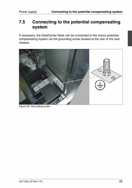
7.5 Connecting to the potential compensatingsystem
If necessary, the DataCenter Rack can be connected to the indoor potential-compensating system via the grounding screw located at the rear of the rackchassis.
Figure 26: Grounding screw
U41145-J-Z146-1-74 45


U41145-J-Z146-1-74 47
Related publicationsThe CD-ROM delivered with each server system also contains the PDF file forthe DataCenter Rack manual.
The PDF files for the manuals listed below can also be downloaded free ofcharge from the Internet. The overview page showing the online documentationavailable in the Internet can be found via the URL:http://manuals.fujitsu-siemens.com
[1] Safety, Warranty and Ergonomics


Index
19-inch rack technology 7
Aadd-on rack 2
setting up 23air circulation 8anti-tilt bracket 13
mounting 22articulated cable guide 8, 26
mounting 32assembly aid 19
Bbasic rack 23
Ccable
connecting 34disconnecting 34routing 35
cable clip 26, 27cable guide
articulated 35with cable clips 8, 33
cable management 8, 31cage nut 17
inserting 17mounting 17
chipcard 15chipcard reader 15chipcard symbol 15consumables 11
DDataCenter Rack 1delivery unit 13dimensions 5direct connection 8, 40disposal 12DOCcert seal 4
Eenvironmental conditions 5environmental protection 11ergonomics 3expansion area 25, 28
Ggrounding screw 45guarantee 3
Hheight 5height unit (HU) 16high-availability 41hot-plug disk drive 9hot-replace 8hot-replace slot 26HU (height unit) 16
Iinstallation
planning 10preparing 13system architect 19
Kkeys 13, 15
Llabels 11
on plastic housing parts 11load capacity 26
Mmains
connecting device 34mains connection
rack 41maintenance 26mounting
anti-tilt bracket 22articulated cable guide 32
U41145-J-Z146-1-74 49
Index
cable guide 33cable management 31cage nut 17frame holder 28horizontally 25in front 19-inch area 26in rear 19-inch area 30in the expansion area 28rack components 25spring nut 17support bracket 27vertically 25
mounting area 25
Ppackaging 11palette 13power supply 41
with UPS 44power supply module 9protection class 6
Rrack
19-inch technology 1, 7add-on rack 2components 25external dimensions 5installation 20installation concept 7internal dimensions 5mains connection 41opening 15philosophy 7setting up 21transport concept 7unpacking 13variants 5ventilation concept 8
rack components 25rack variants
add-on rack 5basic rack 5
recycling 12
routingcable 35, 39, 40
Ssecurity 3setting up
add-on rack 23rack 21
sliding rails 7, 26spring nut 17
inserting 18mounting 17
standards 6support bracket 26system architect 19
Ttake-back
devices and consumables 12technical data 5telescopic rails 7, 26terminal strip 42TÜV 4
UUPS 44
Vventilation 5
Wweight 5width 5width 41
50 U41145-J-Z146-1-74

Comments on DataCenter Rack
U41145-J-Z146-1-74
CommentsSuggestionsCorrections
�
Submitted by
Fujitsu Siemens Computers GmbHUser Documentation81730 MunichGermany
Fax: (++49) 700 / 372 00000
Internet: [email protected]://manuals.fujitsu-siemens.com

Comments on DataCenter Rack
U41145-J-Z146-1-74
CommentsSuggestionsCorrections
�
Submitted by
Fujitsu Siemens Computers GmbHUser Documentation81730 MunichGermany
Fax: (++49) 700 / 372 00000
Internet: [email protected]://manuals.fujitsu-siemens.com


Information on this document On April 1, 2009, Fujitsu became the sole owner of Fujitsu Siemens Compu-ters. This new subsidiary of Fujitsu has been renamed Fujitsu Technology So-lutions.
This document from the document archive refers to a product version which was released a considerable time ago or which is no longer marketed.
Please note that all company references and copyrights in this document have been legally transferred to Fujitsu Technology Solutions.
Contact and support addresses will now be offered by Fujitsu Technology So-lutions and have the format …@ts.fujitsu.com.
The Internet pages of Fujitsu Technology Solutions are available at http://ts.fujitsu.com/... and the user documentation at http://manuals.ts.fujitsu.com.
Copyright Fujitsu Technology Solutions, 2009
Hinweise zum vorliegenden Dokument Zum 1. April 2009 ist Fujitsu Siemens Computers in den alleinigen Besitz von Fujitsu übergegangen. Diese neue Tochtergesellschaft von Fujitsu trägt seit-dem den Namen Fujitsu Technology Solutions.
Das vorliegende Dokument aus dem Dokumentenarchiv bezieht sich auf eine bereits vor längerer Zeit freigegebene oder nicht mehr im Vertrieb befindliche Produktversion.
Bitte beachten Sie, dass alle Firmenbezüge und Copyrights im vorliegenden Dokument rechtlich auf Fujitsu Technology Solutions übergegangen sind.
Kontakt- und Supportadressen werden nun von Fujitsu Technology Solutions angeboten und haben die Form …@ts.fujitsu.com.
Die Internetseiten von Fujitsu Technology Solutions finden Sie unter http://de.ts.fujitsu.com/..., und unter http://manuals.ts.fujitsu.com finden Sie die Benutzerdokumentation.
Copyright Fujitsu Technology Solutions, 2009