Embed Size (px)
Citation preview

Deploying an Oracle Optimized Warehouse on Dell PowerEdge Servers and Dell | EMC Storage 1
Deployment of Oracle® Optimized Warehouse
On DellTM
PowerEdgeTM
Servers and Dell/EMC
Storage A Dell Technical White Paper
Database Solutions
Engineering
By David Mar and Naveen Iyengar Dell | Solutions Engineering
January 2010

Deploying an Oracle Optimized Warehouse on Dell PowerEdge Servers and Dell | EMC Storage 2
THIS WHITE PAPER IS FOR INFORMATIONAL PURPOSES ONLY, AND MAY CONTAIN TYPOGRAPHICAL ERRORS AND TECHNICAL INACCURACIES. THE CONTENT IS PROVIDED AS IS, WITHOUT EXPRESS OR IMPLIED WARRANTIES OF ANY KIND.
Dell, the DELL logo, the Dell badge, and PowerEdge are trademarks of Dell Inc.; Intel is a
registered trademark of Intel Corporation in the U.S. and other countries; Oracle is a registered trademark of Oracle Corporation and/or its affiliates; EMC is the registered trademark of EMC Corporation.

Deploying an Oracle Optimized Warehouse on Dell PowerEdge Servers and Dell | EMC Storage 3
ABSTRACT .................................................................................................................................................. 4
INTRODUCTION ........................................................................................................................................ 4
DATA WAREHOUSE DIFFERENCES OVER ONLINE TRANSACTIONAL PROCESSING
SYSTEMS (OLTP) ....................................................................................................................................... 5
SIZING YOUR DATA WAREHOUSE INFRASTRUCTURE ................................................................ 6
DISK SPACE VERSUS DISK SPINDLES: ........................................................................................................ 6 PERFORMANCE AND SCALABILITY: ............................................................................................................ 6 BALANCED CONFIGURATION: ..................................................................................................................... 7
SCALING A SYSTEM WITHOUT BLOCKS: ............................................................................................. 8
SCALING A SYSTEM WITH BLOCKS: ..................................................................................................... 9
DELL SOLUTIONS FOR ORACLE DATABASE ..................................................................................11
ARCHITECTURE OVERVIEW ...............................................................................................................11
SINGLE-BLOCK CONFIGURATION ..............................................................................................................12 MULTIPLE BUILDING BLOCKS ...................................................................................................................13 ADVANTAGE WITH STANDARDIZATION .....................................................................................................14
REFERENCE DESIGN FOR HIGH AVAILABILITY ..........................................................................15
SAN CONFIGURATION ...............................................................................................................................15 CONFIGURING LUNS .................................................................................................................................16
SERVER CONFIGURATION .....................................................................................................................18
CONFIGURING FULLY REDUNDANT ETHERNET INTERCONNECTS ...........................................................18 CONFIGURING DUAL HBAS FOR DELL/EMC CX STORAGE ....................................................................19 CONFIGURING DUAL NICS FOR PRIVATE NETWORK ...............................................................................19
SOFTWARE CONFIGURATION .............................................................................................................19
CONFIGURING THE PRIVATE NIC TEAMING .............................................................................................19 CONFIGURING THE SAME PUBLIC NETWORK INTERFACE NAME ON ALL NODES ....................................19 CONFIGURING SSH AND RSH .................................................................................................................19 CONFIGURING SHARED STORAGE FOR THE DATABASE USING THE ASM LIBRARY DRIVER ..................19 ORACLE PARAMETERS .............................................................................................................................21
CONFIGURATION DELIVERABLES LIST ............................................................................................24
DELL SOLUTION FOR ORACLE OPTIMIZED WAREHOUSE PHASE III ........................................................24
CONCLUSION ............................................................................................................................................26
APPENDIX...................................................................................................................................................27
CONTENTS

Deploying an Oracle Optimized Warehouse on Dell PowerEdge Servers and Dell | EMC Storage 4
Abstract This white paper provides an architectural overview and configuration guidelines for deploying Oracle Optimized Warehouses on Enterprise Linux 5, Dell PowerEdge servers and Dell/EMC storage. Using the knowledge gained through joint development, testing and support with Oracle and EMC, this Dell Reference Configuration documents best practices that can help speed data warehouse solution implementation, help simplify operations, and improve performance and availability. The configurations outlined are optimized for different sets of customer data warehouse requirements accounting for software, hardware, storage, I/O, and networking into a configuration based on extensive technical knowledge and customer experience.
Introduction Oracle’s Optimized Warehouse Initiative (OWI) provides a validated, balanced approach that combines software, hardware, storage, I/O, and networking into a configuration optimized for pre-determined data warehouse requirements. Using our extensive joint field experience and technical knowledge, Dell Inc., EMC and Oracle have defined and qualified system configurations for data warehouses of varying raw data volume, average concurrent users and workload complexity. Qualification covers not only a single set of server, storage, and software stacks, but the ability to support scaling via clustering of such system configurations. The Oracle Optimized Warehouse Initiative on Dell and EMC defines Oracle data warehouse reference configurations that deliver a prescribed database, server, and storage mix optimized for data warehousing applications. These reference configurations simplify the implementation of data warehouses through pre-defined building blocks. Each building block characterizes known data requirements suitable to typical data warehouse oriented deployments. Balancing the servers, storage, and interconnect aspects of the infrastructure ensures that all interacting components are used in the most optimal manner to deliver the highest possible performance for typical processing and IO load patterns for Oracle data warehouses in the specified size ranges. Under Oracle’s new guidelines for Optimized Warehouse Initiative, they have found that customers most often deploy data warehouses under three separate paradigms:
High performance – May be characterized by typical business queries that are expected to be processed in seconds or low number of minutes.
Mainstream – Where the average user queries are expected to be handled in minutes or within 1 hour.
High capacity – Where most queries tend to pass significant portions of the stored warehouse data, performing very detailed processing and analysis of each data item for generating comprehensive reporting. This working model tends to be more batch-oriented and will often require additional time (hours, overnight, weekends, etc.)
Data warehouse reference configurations published under the Oracle Optimized Warehouse Initiatives align to a known requisite capacity and are designed for mainstream scenarios. When the requirement is for high performance, more blocks may typically have to be deployed for a targeted warehouse size; therefore the expected warehouse data volume may be reduced. Conversely, more data volume can be supported by each block if the query time requirement is relaxed to hours or days as with many typical batch report systems. For more information on the Oracle Optimized Warehouse Initiative, visit http://www.oracle.com/solutions/business_intelligence/optimized-warehouse-initiative.html
Deploying an Oracle Optimized Warehouse on Dell PowerEdge Servers and Dell | EMC Storage 5
Dell™ PowerEdge™ servers and Dell/EMC storage systems are ideal choices to deploy highly reliable and sustainable Oracle Optimized Warehouses. This Reference Configurations white paper is intended to help IT professionals to design and configure Oracle Optimized Warehouses for data warehousing solutions, using Dell servers and storage and applying best practices derived from laboratory and real-world experiences.
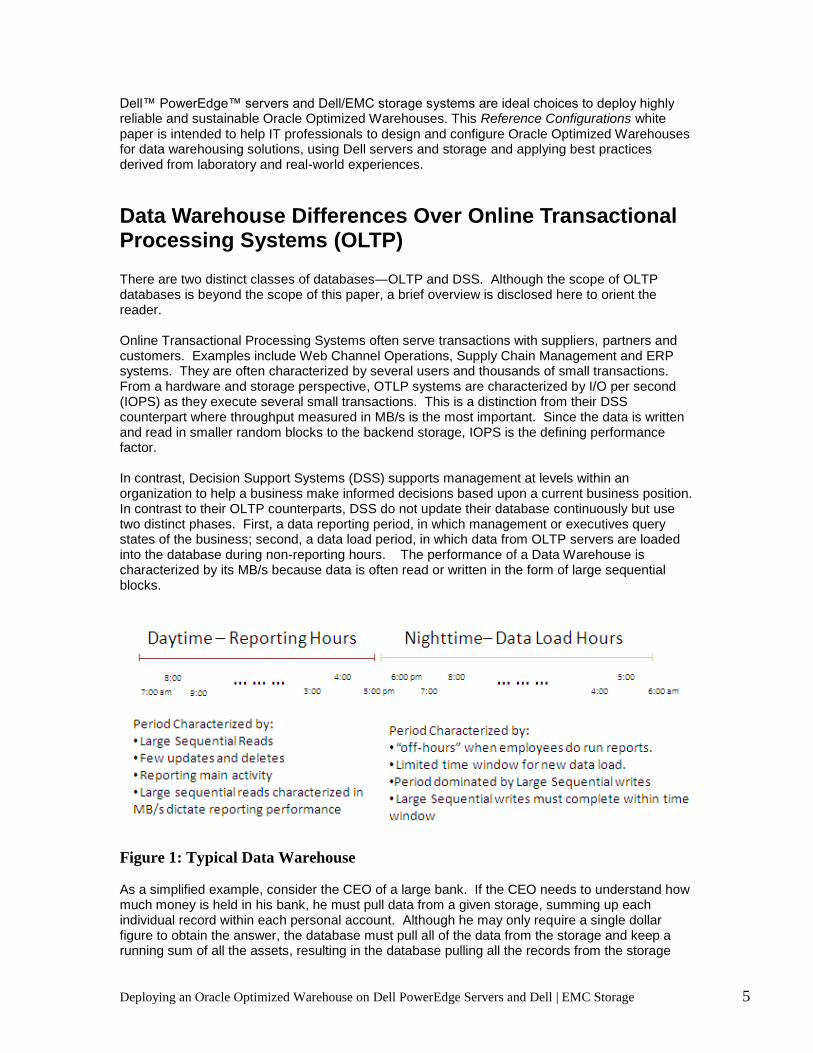
Data Warehouse Differences Over Online Transactional Processing Systems (OLTP) There are two distinct classes of databases―OLTP and DSS. Although the scope of OLTP databases is beyond the scope of this paper, a brief overview is disclosed here to orient the reader. Online Transactional Processing Systems often serve transactions with suppliers, partners and customers. Examples include Web Channel Operations, Supply Chain Management and ERP systems. They are often characterized by several users and thousands of small transactions. From a hardware and storage perspective, OTLP systems are characterized by I/O per second (IOPS) as they execute several small transactions. This is a distinction from their DSS counterpart where throughput measured in MB/s is the most important. Since the data is written and read in smaller random blocks to the backend storage, IOPS is the defining performance factor. In contrast, Decision Support Systems (DSS) supports management at levels within an organization to help a business make informed decisions based upon a current business position. In contrast to their OLTP counterparts, DSS do not update their database continuously but use two distinct phases. First, a data reporting period, in which management or executives query states of the business; second, a data load period, in which data from OLTP servers are loaded into the database during non-reporting hours. The performance of a Data Warehouse is characterized by its MB/s because data is often read or written in the form of large sequential blocks.
Figure 1: Typical Data Warehouse As a simplified example, consider the CEO of a large bank. If the CEO needs to understand how much money is held in his bank, he must pull data from a given storage, summing up each individual record within each personal account. Although he may only require a single dollar figure to obtain the answer, the database must pull all of the data from the storage and keep a running sum of all the assets, resulting in the database pulling all the records from the storage
Deploying an Oracle Optimized Warehouse on Dell PowerEdge Servers and Dell | EMC Storage 6
and summing the result. To achieve this daytime reporting operation in an optimized manner, this requires a high level of MB/s from the storage backend to the server which is summing the result. This reporting phase is characterized by few updates and inserts and primarily used for reporting. The second phase commonly found in data warehouse implementation is the data load phase. This phase occurs during the evening in which data load must be completed before the reporting period begins the next day. This is characterized by large sequential writes which must be completed before the beginning of the next reporting period. This phase is driven by large sequential writes, and its time span is dictated by the overall MB/s for the writes.
Sizing Your Data Warehouse Infrastructure This section considers the key factors to keep in mind while sizing one’s infrastructure for Data Warehouse and how Dell Oracle’s Optimized Warehouse provides a balanced block configuration approach to handle these key factors to optimize performance and scalability.
Disk Space Versus Disk Spindles:
In recent years, although the disk capacities have increased tremendously the speed or the data transfer rates of these disks have not been able to keep up at the same rate. Although currently available disk capacities are as large as 2TBytes, and also considering the fact that storage is one of the more expensive components in your SAN infrastructure, one of the potential trivial mistakes when sizing storage is to size it purely based upon the capacity needed for the data. It is important to realize that although these large disks can provide the space and capacity you need for your data, each one of the disks can deliver only a certain amount of throughput that is measured in terms of MB/s. Thereby, the database performance is typically determined by the number of disks over which the data is stored and not their capacity. Hence, one of the key factors when you size your storage is to determine the number of disks needed to meet your Database performance needs, else it can lead to some poor performance and scalability. It is also essential, especially in a Data Warehouse environment, to size your backend storage according to the sustained throughput that your Storage Processor can deliver. While you need to size your number of backend spindles according to the desired performance as mentioned above, the Storage Processor can deliver the required performance level only up to a certain spindle count. Beyond that spindle count threshold, the Storage Processor cannot sustain the performance level, and as a result, it is recommended that you add another Storage Processor Enclosure (SPE) in order to guarantee throughput sustainability.
Performance and Scalability: Although sizing you backend storage with the right number of disks is one of the key factors to achieve the desired degree of database performance, it is not the only factor. In a Data Warehouse environment, the overall throughput of the infrastructure is the driving force of the database performance. However, the potential throughput that an infrastructure can deliver can be limited by key factors such as the processing power, the memory, and the SAN I/O sub-system. A balanced configuration of these key elements needs to be discovered to prevent the consequently limited performance and non-linear scalability. Even a DBA trying to optimize or fine-tune at the database software layer by partitioning tables, having multiple streams, etc., will only be limited by the maximum performance of an unbalanced configuration, which will not be the true optimal performance that the hardware can deliver and thereby under-utilizes the infrastructure. In the following sections, we will see how Dell Oracle’s Optimized Warehouse building blocks help to solve this problem and achieve this balanced configuration.

Deploying an Oracle Optimized Warehouse on Dell PowerEdge Servers and Dell | EMC Storage 7
Balanced Configuration: The OWI project is based upon a balanced configuration where the CPU, memory and I/O subsystems are balanced. This means that the processors, memory, and SAN I/O sub-system for each block are calibrated against each other to provide balanced blocks. But why is a balanced configuration useful? To answer that question, we must first look at its antithesis, an unbalanced configuration building block. The first figure shows where CPU utilization would eventually peak out and cause the system to not enable further user load scaling if no other constraints are present. This is represented by the red “x”. The second figure shows the system starting with a given amount of free memory, then continuing to add user load, and finally beginning to use the swap space as shown by the flat horizontal line. Eventually, due to increasing memory needs, the system will not be able to handle any more user load, which is represented by the red “x”. The last figure shows the SAN I/O sub-system where the system will eventually not be able to accept more user load due to the limitations of the storage system. However, in one complete block comprised of both server and storage, there is often a limiting factor. In the graph shown below, memory is the limiting factor. Due to this, the maximum user load will be dependent upon this limiting factor. This is important to note, as when building a cluster, adding additional blocks will only scale at most by the limiting factor. Consequently, adding a second block will double potential performance but in an unbalanced configuration will only double by the least common denominator as noted by the dashed vertical blue line.

Deploying an Oracle Optimized Warehouse on Dell PowerEdge Servers and Dell | EMC Storage 8
Figure 2 – CPU, Memory and SAN I/O Performance in an Unbalanced
Configuration
Scaling a System Without Blocks:
One possible approach to scaling a system is to continuously attempt to fix that least performing component or the bottleneck. This approach could be used for any of the three components shown here: I/O, Memory, or CPU-bound blocks. For example, one of the most common bottlenecks is the disk I/O. To improve the maximum storage I/O, one possibility is to add disks. It is also possible to improve the disk I/O by adding more disks; however, there is a point at which the I/O performance improvement increase

Deploying an Oracle Optimized Warehouse on Dell PowerEdge Servers and Dell | EMC Storage 9
becomes non-linear. For instance, adding 10 disks may provide X performance. And given that the performance is not limited by other bottlenecks, adding 10 more disks may add 2X more performance and adding 3X many disks may yield 3X performance. Eventually, however, the performance increase will begin to show less linear scalability with the addition of disks because from a certain point on, the storage processor will become the limiting factor. Hence, adding 10X times may well not demonstrate 10X increase in I/O performance. This is problematic in that predictable scalability becomes complex and throughput and performance sustainability is not guaranteed.
Scaling a System With Blocks:
As a result, if maximizing scalability while maintaining throughput at the time of need is necessary, Dell advocates a scale-out methodology. This implies adding blocks comprised of a balanced solution of a server’s memory, CPU, and I/O subsystem. To make the most of this methodology, Dell, Oracle, and EMC have worked together to create balanced building blocks. Each component of these blocks is designed not to be a bottleneck at any one component but rather to simultaneously be optimized to provide better scalability. The figure below illustrates that no single system component serves as the bottleneck in a block. Doubling a block or adding nodes to the block will then scale more optimally as each block can handle greater user loads.

Deploying an Oracle Optimized Warehouse on Dell PowerEdge Servers and Dell | EMC Storage 10
Figure 3 – CPU, Memory and SAN I/O Performance in a Balanced Configuration

Deploying an Oracle Optimized Warehouse on Dell PowerEdge Servers and Dell | EMC Storage 11
Dell Solutions for Oracle Database Dell Solutions for Oracle Database are designed to simplify operations, improve usability, and cost-effectively scale as your needs grow over time. In addition to providing server and storage hardware, Dell solutions for Oracle include:
Dell Configurations for Oracle ― In-depth testing of Oracle configurations for high-demand solutions; documentation and tools that help simplify deployment
Integrated Solution Management ― Standards-based management of Dell Solutions for Oracle that can lower operational costs through integrated hardware and software deployment, monitoring, and updating
Oracle Licensing ― Multiple licensing options that can simplify customer purchase
Dell Enterprise Support and Infrastructure Services for Oracle ― Including offerings for the planning, deployment, and maintenance of Dell Solutions for Oracle Database
For more information concerning Dell Solutions for Oracle Database, please visit http://www.dell.com/oracle.
Architecture Overview The basis for the Oracle Optimized Warehouse is to enable module growth. In this configuration, a single building block for the Oracle Optimized Warehouse phase III for Dell/EMC consists of one dual-socket Dell PowerEdge R710 server, two Brocade DS5100 fibre-channel (FC) switches, and two Dell/EMC CX4-120 storage systems. A balanced building block is comprised of the following: • One Dell PowerEdge R710 server consisting of 2-way Quad core CPUs and 64 GB of RAM • Two Dell/EMC CX4-120 storage systems fully expanded to16 front and back-end FC connections • Two Brocade DS5100 48 x 4Gb/s ports • Two QLOGIC QLE2560 single port FC HBAs (8Gb/s ports) • Oracle or Red Hat Enterprise Linux release 5.3 for x86_64. • Oracle Database Enterprise Edition with Real Application Cluster support release 11.1.0.7 with partitioning option • Oracle Automatic Storage Management (ASM) organization for data store • EMC PowerPath for host IO multipathing (PP 5.3 for Enterprise Linux 5.3 x86_64) • Client-server network made up of network controllers, cables, and switches • 10 Gigabit Ethernet switches for cluster interconnect network

Deploying an Oracle Optimized Warehouse on Dell PowerEdge Servers and Dell | EMC Storage 12
Single-Block Configuration Dell and Oracle have worked together to create a set of Data Warehouse Reference configurations that enable customers to start building a data warehouse based upon best practices and experience from the leaders in the data warehousing industry. Each of these configurations starts with a base building block that is optimized for different scales of customer data warehouse requirements accounting for software, hardware, storage, I/O and networking into a configuration based upon extensive technical knowledge and customer experience. The base configuration begins with a reference configuration as depicted below.
Figure 4 – Architectural Overview of Single-Block Oracle Optimized Warehouse
Dell PowerEdge R710
Fibre Channel Switches
Dell| EMC CX4-120 Storage Arrays
Public Network
FC Network

Deploying an Oracle Optimized Warehouse on Dell PowerEdge Servers and Dell | EMC Storage 13
This system configuration defined as a Dell/Oracle/EMC OWI base block is qualified under the Oracle OWI process to target a deployment starting with around 5TB of data supporting a mainstream type requirement.
A single Dell Building block for an Oracle Optimized Warehouse has two fibre-channel switches to provide host-side multi-pathing and balance the I/O load placed on the CX4 Storage arrays. A single block also consists of two CX4 Storage Processor Enclosure (SPE) Arrays with each connected to one DAE-OS and a DAE respectively, giving it a total of 4 DAEs in 1 block. Each of the two DAEs is connected to its respective SPE through a separate back-end loop― they are not daisy-chained to each other. A multi-headed (two) storage configuration per block is recommended to sustain the required throughput.
Multiple Building Blocks
Over time, as data warehouses mature, the underlying system that supports the deployment must be able to handle growth in both the number of concurrent user queries against the system as well as the increasing volume of data required by the queries. When the growth pushes the limits of the initial system block deployed, additional similar system blocks can be readily clustered to support the growth. The key is that each additional block adds a balanced amount of server processing and storage IO support capability. Using pre-tested and validated commodity components that enable balanced growth provides a model to consistently and reliably enable performance and size quickly while leveraging Oracle database Real Application Cluster methodology. Customers deploying with the OWI configurations will have a clear path to accommodate growth with a simple and well-defined process. When extreme high performance is required, blocks may be added to the mainstream configuration enabling performance scaling that may be pushing the limit of a single block. Conversely, when service level is relaxed, a larger volume of data can be processed through fewer (or one) blocks than the mainstream recommendations to free up more headroom in the supporting infrastructure for other, more critical, requirements. The following is a diagram of a qualified multi-block scale-out configuration.

Deploying an Oracle Optimized Warehouse on Dell PowerEdge Servers and Dell | EMC Storage 14
Figure 5 - Architectural Overview of Multi-Block Oracle Optimized Warehouse In the above figure, the balanced building block differs from many typical models with only one configured SAN module to many server nodes. In contrast, the Optimized Warehouse approach attempts to grow a solution in a linear manner by incrementally adding balanced building blocks for scalability. Consequently, growth of this 2 block solution to a three block solution would involve adding a complete building block which would increment the RAC by a third PowerEdge R710 server and two more Dell | EMC CX4 storage arrays. Such a paradigm ensures linear scalability and predictability in performance and growth characteristics.
Advantage With Standardization
PowerConnect Gigabit
Ethernet Switches for Private
Interconnect
Dell PowerEdge R710
Fibre Channel Switches
Dell| EMC CX4-120 Storage Arrays
SPB SPA SPB SPA SPB SPA SPB SPA
Public Network
FC Network
Private Network

Deploying an Oracle Optimized Warehouse on Dell PowerEdge Servers and Dell | EMC Storage 15
Dell PowerEdge servers are designed to deliver high performance for critical enterprise applications such as data warehousing, messaging, web services and infrastructure applications. As proprietary systems are increasingly replaced by industry-standard systems, applications like databases, high-performance computing clusters, and messaging systems can take advantage of the performance and scalability of the PowerEdge servers. Combined with Dell storage systems, customers can easily deploy these PowerEdge servers as building blocks of a scalable enterprise, consolidating and virtualizing both the computing resources as well as the storage resources. The Dell/EMC storage subsystem delivers advanced storage capabilities, including simple management tools, continuous data availability and integrity, exceptional price/performance, data mobility, and scalability between multiple storage tiers. The Dell/EMC storage subsystem is offered in various models, ranging from affordable entry-level solutions to high-performance, maximum-capacity configurations for your most demanding requirements. All Dell/EMC CX4 series arrays support advanced software, including local replication for backup/restore, remote replication for disaster recovery, and data mobility. The Dell/EMC is architected with two storage processors to guard against a single point of failure.
Reference Design for High Availability
SAN Configuration
Figure 6 – Two-Block SAN Configuration
Figure 6 illustrates the cabling of scaling with building-blocks within cluster hosting Oracle Database 11g and the CX storage array where the data resides. As mentioned in the “Architectural Overview” section above, each CX4 storage array has two storage processors
Dell PowerEdge R710
Brocade SW5100 FC Switch Brocade SW5100 FC Switch
Dell PowerEdge R710
SPB SPA
Server 1 w/ 2 HBAs Server 2 w/ 2 HBAs
Port 0 Port 0 Port 0
FC Network
Dell| EMC CX4-120 Storage Arrays
Port 0

Deploying an Oracle Optimized Warehouse on Dell PowerEdge Servers and Dell | EMC Storage 16
(SP), called SPA and SPB, which can access all of the disks in the system and provide the physical storage capacity for the Oracle RAC database. Before data can be stored, the CX4 physical disks must be configured into different components known as RAID groups and LUNs. A RAID group is a set of physical disks that are logically grouped together. Each RAID group can be divided into one or more LUNs which are logical entities that the server uses to store data. The RAID level of a RAID group is determined when binding the first LUN within the RAID group. It is recommended to bind one LUN per RAID group for database workloads to avoid disk spindle contention. For details on LUN configuration, please refer to the “Configuring LUNs” section below.
In the CX4 array, the LUNs are assigned to and accessed by the Oracle Database 11g cluster nodes directly through one storage processor. In the event of a storage processor port failure, traffic will be routed to another port on the same SP if the host is connected to more than one SP port and the EMC PowerPath multi path software is used. In the event of a storage processor failure, LUNs on the failed processor will trespass to the remaining storage processor. Both events could result in interrupted service unless multiple I/O paths are configured between the Oracle 11g RAC database hosts and the CX4 array. Therefore, it is crucial to eliminate any single point of failures within the I/O path.
At the interconnect level, it is recommended that each node of the Oracle 11g RAC database cluster have two HBAs with independent paths to both storage processors. With the EMC PowerPath software installed on the cluster node, I/O can be balanced across HBAs as well. It is a best practice to hard set both the HBA ports and the switch ports to operate at 4 GB/s throughput to allow proper I/O path auto recovery. It is also recommended that two Fibre Channel switches are used because in the event of a switch failure in a single Fibre Channel switch fabric environment, all hosts will lose access to the storage until the switch is physically replaced and the configuration restored. In addition, since I/O blocks are now split across multiple switches, the I/O throughput pushed to the FC backend will not be held up by the switches.
Configuring LUNs A LUN is a logical unit of physical disks presented to the host connected to the CX4 storage. The storage for an Oracle Database 11g data warehouse can be divided into the following three areas. At a minimum, the following LUNs must be available.
• The first area is for the Oracle Cluster Registry (OCR), the Clusterware Cluster Synchronization Services (CSS) Voting Disk, and the Server Parameter File (SPFILE) for the Oracle Automatic Storage Management (ASM) instances. Oracle best practices advise that there should be at minimum 3 voting LUNs and two OCR LUNs. Dell recommends adherence to this policy through either use of a hardware raid solution leveraging some form of hardware mirroring, or in the absence of such technology to allocate LUNs and disks for each.
• The second area is for database data that is stored in the physical files of Oracle
database including datafiles, online redo log files, control files, SPFILE for the database instances, and temp files for the temporary tablespaces. It is generally advisable to have more than one LUN for the database area so that ASM may spread the load across the disk efficiently.
• The third area is for the Oracle Flash Recovery Area which is a storage location for
all recovery-related files. The disk-based database backup files are stored in the Flash Recovery Area. The Flash Recovery Area is also the default location for all archived redo log files.

Deploying an Oracle Optimized Warehouse on Dell PowerEdge Servers and Dell | EMC Storage 17
It is a best practice to separate the above three storage areas into their own LUNs on different Disk Groups / RAID Groups. The separation can enable better I/O performance by ensuring that these files do not share the same physical disks. Figure 7 illustrates a sample RAID group and LUN configuration on a Dell/EMC CX4 storage array with two CX4 Storage Processor Enclosures (SPE) connected to one DAE0-OS and one DAE1 respectively. The two DAEs per SPE as noted in the figure 7 below are connected through two backend loops and are not daisy-chained. There are separate partitions for the three storage areas described above. Spindles 0 through 4 in the DAE0-OS in the figure below contain the operating system for the storage as well as the redundant OCR and Voting Disks. These spindles are also used during power outage to store the system cache data. It is not recommended to use the operating system spindles for Oracle Data Files or Flash Recovery Area. One disk from each of the DAE-OS is used as a Hot Spare, leaving 18 Disks from the two DAE-OS arrays for Data. Another 30 disks from the 2
nd set of DAEs altogether provide 48 disks for Oracle Data. The
Oracle Data Files and Flash Recovery Area (FRA) are spread out over these 48 Data disks as 2+1 RAID5 groups. Note that the typical large sequential read characteristics of a Data Warehouse environment apply only at the Oracle ASM (Allocation Unit) logical layer. These requests usually translate into several random reads at the storage physical layer. Hence as noted in the figure below, for a Data Warehouse environment, a narrower RAID5 i.e. 2+1 R5 is recommended as opposed to a 4+1 RAID5 to reduce the number of disk heads that need to move to seek these random chunks of data, thereby reducing the seek latencies and increasing the throughput. For more details on the 2+1 RAID 5 configuration, see the Appendix section.
Figure 7 - Disk Array Layout

Deploying an Oracle Optimized Warehouse on Dell PowerEdge Servers and Dell | EMC Storage 18
Server Configuration
Configuring Fully Redundant Ethernet Interconnects
Each Oracle Database 11g RAC server needs at least two network interface cards (NICs), one for the external interface and one for the private interconnect network. The servers in an Oracle RAC are bound together using cluster management software called Oracle Clusterware, which enables the servers to appear as though they were a single server. Servers in the cluster communicate with each other using a dedicated private network also known as the cluster interconnect. One of the servers in the Oracle RAC cluster is assigned as the master node. In the event of an interconnect NIC failure in a single interconnect NIC environment, the server loses communication with the master node, and the master node will initiate recovery of the failed database instance on the server. In the event of a network switch failure in a single private network switch environment, a scenario will result equivalent to the failure of every single node in the cluster except for the designated master node. The master node will then proceed to recover all of the failed instances in the cluster before providing a service from a single node which will result in a significant reduction in the level of service available. Therefore, the implementation of a fully redundant interconnect network configuration is recommended, with redundant private NICs on each server and redundant private network switches.
Figure 8 illustrates the CAT 5E/6 Ethernet cabling of a fully redundant interconnect network configuration of a two-node PowerEdge Oracle RAC cluster, with two private NICs on each server, and two private network switches. For this type of redundancy to operate successfully, it requires the implementation of the Link Aggregation Group, where one or more links are provided between the switches themselves.
The implementation of a fully redundant interconnect configuration requires for NIC teaming software to be put into operation at the operating system level. This software works at the network driver level to provide two physical network interfaces to operate underneath a single IP address. For details on configuring NIC teaming, please refer to the “Configuring the Private NIC teaming” section below.
Figure 8 - Ethernet Cabling a Fully Redundant Private Interconnect Network
Dell PowerEdge R710 Server Dell PowerEdge R710 Server
Dell PowerConnect 5424
Gigabit Ethernet Switch
Dell PowerConnect 5424
Gigabit Ethernet Switch
Link Aggregation Group

Deploying an Oracle Optimized Warehouse on Dell PowerEdge Servers and Dell | EMC Storage 19
Configuring Dual HBAs for Dell/EMC CX Storage
As illustrated in the previous section on SAN configuration, it is recommended that two HBAs be installed on each of the PowerEdge servers that host the Oracle 11g RAC database because in the event of an HBA failure in a single HBA fabric environment the host will lose access to the storage until the failed HBA is physically replaced. Using dual HBAs provides redundant links to the CX storage array.
Configuring Dual NICs for Private Network
As illustrated in Figure 8, it is recommended that two private NICs be installed on each of the PowerEdge servers hosting the Oracle 11g RAC database to provide redundant private network links. In the event of a NIC failure in a single private NIC environment, Oracle Clusterware will remove the node from the cluster.
Dell Reference Configuration for Oracle Optimized Warehouse
Software Configuration
Configuring the Private NIC Teaming
As mentioned in the Section “Configuring Fully Redundant Ethernet Interconnects” above, it is advisable to install two physical private NICs on each of the Oracle 11g RAC cluster servers to help guard against private network communication failures. In addition to installing the two NICs, it is required to use NIC teaming software to bond the two private network interfaces together to operate under a single IP address, providing failover functionality. If a failure occurs, affecting one of the NIC interfaces―examples include switch port failure, cable disconnection, or failures of the NIC itself―network traffic is routed through the remaining operable NIC interface. Failover occurs transparently to the Oracle RAC database with no network communication interruption or changes to the private IP address.
Configuring the Same Public Network Interface Name on All Nodes
It is important to ensure that all nodes within an Oracle 11g RAC cluster have the same network interface name for the public interface. For example, if “eth0” is configured as the public interface on the first node, then “eth0” should also be selected as the public interface on all of the other nodes. This is required for the correct operation of the Virtual IP (VIP) addresses configured during the Oracle Clusterware software installation.
Configuring SSH and RSH
During the installation of Oracle 11g RAC software, the Oracle Universal Installer (OUI) is initiated on one of the nodes of the Oracle RAC cluster. OUI operates by copying files to and running commands on the other servers in the cluster. In order to allow OUI to do that, the secure shell (SSH) and remote shell (RSH) must be configured, so that no prompts or warnings are received when connecting between hosts via SSH or RSH as the oracle user. To prevent unauthorized users from accessing the systems, it is suggested that RSH be disabled after the Oracle software installation.
Configuring Shared Storage for the Database Using the ASM Library Driver
Oracle Automatic Storage Management (ASM) is a feature of Oracle Database 11g that provides the database administrator (DBA) with a simple storage management interface that is consistent across all server and storage platforms. ASM virtualizes the database storage into disk groups. ASM distributes data evenly across all disks within a disk group to optimize performance and utilization. ASM enables the DBA to change the storage configuration without having to take the
Deploying an Oracle Optimized Warehouse on Dell PowerEdge Servers and Dell | EMC Storage 20
database offline. ASM automatically rebalances files across the disk group after disks have been added or dropped. As discussed in the Section “Configuring LUNs” above, two LUNs are created for the data storage area, and the Flash Recovery Area, respectively. It is recommended that these two LUNs be configured as ASM disks to benefit from the capabilities of ASM. During ASM Instance creation, it is necessary to set the following ASM parameters:
Deploying an Oracle Optimized Warehouse on Dell PowerEdge Servers and Dell | EMC Storage 21
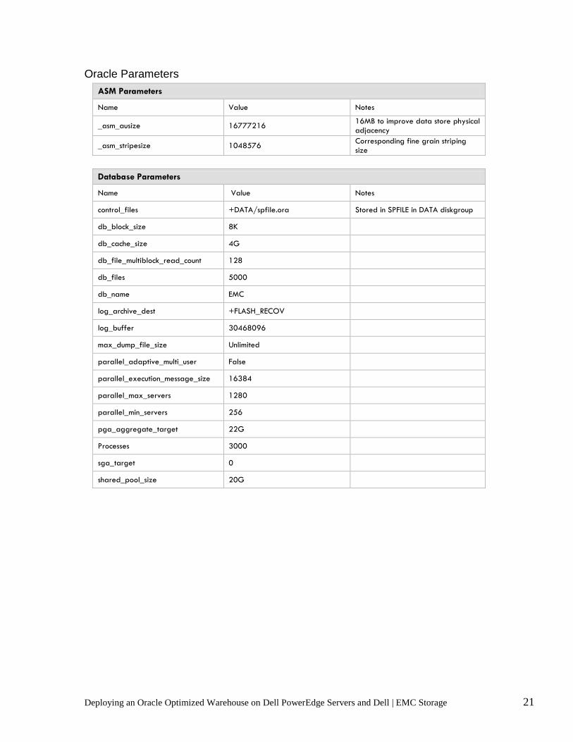
Oracle Parameters
ASM Parameters
Name Value Notes
_asm_ausize 16777216 16MB to improve data store physical adjacency
_asm_stripesize 1048576 Corresponding fine grain striping size
Database Parameters
Name Value Notes
control_files +DATA/spfile.ora Stored in SPFILE in DATA diskgroup
db_block_size 8K
db_cache_size 4G
db_file_multiblock_read_count 128
db_files 5000
db_name EMC
log_archive_dest +FLASH_RECOV
log_buffer 30468096
max_dump_file_size Unlimited
parallel_adaptive_multi_user False
parallel_execution_message_size 16384
parallel_max_servers 1280
parallel_min_servers 256
pga_aggregate_target 22G
Processes 3000
sga_target 0
shared_pool_size 20G

Deploying an Oracle Optimized Warehouse on Dell PowerEdge Servers and Dell | EMC Storage 22
Test Results ― Dell Solution for OWI As part of the joint effort among Dell, Oracle and EMC, the joint engineering teams conducted benchmark tests on one, two, three, and four building block configurations, using I/O-intensive stress tools that simulated Oracle database activity. Each building block was designed to be balanced and to enable growth as necessary as shown below. This table illustrates the I/O throughput in terms of megabytes per second as well as the hardware and software configurations of each of the building blocks. The results of these tests demonstrate the scalability of Dell PowerEdge Servers running Oracle 11g / 11g RAC and ASM with Enterprise Linux 5.
1-BLOCK 2-BLOCKS 3-BLOCKS 4-BLOCKS
WorkLoad High Performance DW 0.86 TB 1.73 TB 2.59 TB 3.46 TB Mainstream DW 2.59 TB 5.18 TB 7.78 TB 10.37 TB High Capacity DW 2.85 TB 5.70 TB 8.55 TB 11.41 TB Key System Specs Expected I/O throughput 1.44 GB/s 2.88 GB/s 4.32 GB/s 5.76 GB/s Limiting Factor Disk Disk Disk Disk Minimum I/O throughput 0.8 GB/s 1.6 GB/s 2.4 GB/s 3.2 GB/s Max User Data 2.85 TB 5.70 TB 8.55 TB 11.41 TB Server Block Details Server R 710 2 x R710 3 x R710 4 x R710 # of nodes 1 2 3 4 CPU Type X86-64 X86-64 X86-64 X86-64 # Cores per CPU 4 4 4 4 Total number of cores 8 16 24 32 Theoretical Throughput 1.6 GB/s 3.2 GB/s 4.8 GB/s 6.4 GB/s Memory Per Node 32 GB 32 GB 32 GB 32 GB Memory Per Core 4 GB 4 GB 4 GB 4 GB Interconnect Node Interconnect 1 GigE 1 GigE 1 GigE 1 GigE Number of interconnects 2 2 2 2 Interconnect throughput 2 2 2 2 Storage Network Network Type Fibre Channel Fibre Channel Fibre Channel Fibre Channel SAN Name Brocade 5100 Brocade 5100 Brocade 5100 Brocade 5100 Number of Switches 2 2 2 2 # Ports Per Switch 24 24 24 24 Switch I/O Throughput per port 4 4 4 4 Total Switch I/O Throughput 19.2 GB/s 19.2 GB/s 19.2 GB/s 19.2 GB/s # HBAs per node 2 2 2 2

Deploying an Oracle Optimized Warehouse on Dell PowerEdge Servers and Dell | EMC Storage 23
# Ports per HBA 1 1 1 1 # Total # of HBA Ports (all nodes) 2 4 6 8 Total HBA Throughput 1.6 GB/s 3.2 GB/s 4.8 GB/s 6.4 GB/s 1-BLOCK 2-BLOCKS 3-BLOCKS 4-BLOCKS
Storage Hardware Storage Disk Array Name / Model CX4-120 CX4-120 CX4-120 CX4-120 # of storage arrays 2 4 6 8 # of disk controllers per array 2 2 2 2 # ports per disk controller 2 2 2 2 Controller I/O Throughput per port 4 GB/s 4 GB/s 4 GB/s 4 GB/s Total Controller Throughput 3.2 GB/s 6.4 GB/s 9.6 GB/s 12.8 GB/s Disk Speed 15000 15000 15000 15000 # data disks per array 24 24 24 24 # total data disks 48 48 48 48 Storage configuration RAID 5 RAID 5 RAID 5 RAID 5 Total Disk I/O Throughput 1.44 GB/s 2.88 GB/s 4.32 GB/s 5.76 GB/s Capacity per disk 266 GB 266 GB 266 GB 266 GB Usable Storage 8.55 TB 17.11 TB 25.66 TB 34.22 TB Data Warehouse User Data 2.85 TB 5.70 TB 8.55 TB 11.41 TB Additional Disks 5 vault drives
1 spare per storage array
5 vault drives 1 spare per
storage array 5 vault drives 1 spare per
storage array 5 vault drives
1 spare per storage array

Deploying an Oracle Optimized Warehouse on Dell PowerEdge Servers and Dell | EMC Storage 24
Configuration Deliverables List Dell Solution for Oracle Optimized Warehouse Phase III
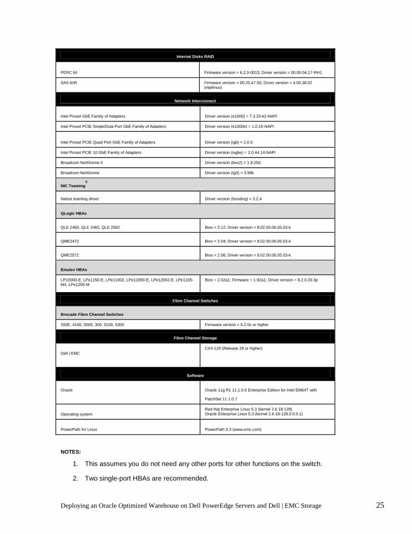
This section contains the Solution Deliverables List (SDL) for the Dell Solution for Oracle Optimized Warehouse Initiative. It contains a detailed listing of server and storage hardware configurations, firmware, driver, OS, and database versions.
Minimum Hardware/Software Requirements (Updated 01/28/10 – for details, see below)
Validated Component(s) Minimum Single Building Block Config
Minimum Multiple Building Block Config
Oracle Software & Licenses Oracle 11gR1 11.1.0.6 Enterprise
Edition (Base) + Oracle Patchset 11.1.0.7
Single Node RAC
Operating System Red Hat Enterprise Linux 5.3 with kernel 2.6.18-128 Oracle Enterprise Linux 5.3 with kernel 2.6.18-128.0.0.0.1
Recommended Support Contract Dell ProSupport and Oracle supported
Supported PowerEdge Servers PowerEdge R710
1 Only 2
Memory All valid PowerEdge memory configurations 32 GB 32 GB (per node)
Dell | EMC FC Storage Array CX4-120 2 2 (per Building Block)
Fibre Channel Switch Brocade SW200E, SW4100,
SW5000, SW300, SW5100,
SW5300,
2 (24 port switch) N/A (For Direct Attached) 2 ((24 port switch for 2-4
Nodes) 1
HBAs Qlogic QLE2460, QLE2462, QLE2562
Emulex LPe1150e LP10000, LPe11002, LPe12000,
LPe12002
2 Single Port HBA per node2 2 Single Port HBA per node
2
Ethernet Interfaces Intel or Broadcom GbE NICs 2
3 (Per Node)3
Ethernet Switches (For Private Interconnect) GbE-only Switches
N/A 2
Raid Controllers (Used for internal storage only) Perc 6/i, SAS 6/iR 1 1 (Per Node)
Internal Drive All valid PowerEdge internal storage configurations 73 GB 73 GB/node
Oracle 11g/11g Database Enterprise Edition and RAC Running on Enterprise Linux 5.3
Minimum Hardware/Software Requirements (Updated 1/28/10 – for details, see below)
Dell PowerEdge Servers
Dell PowerEdge™ Servers
Model BIOS
4 ESM - BMC Firmware
4 Notes
PE R710 1.2.6 1.2 (iDRAC6)
Deploying an Oracle Optimized Warehouse on Dell PowerEdge Servers and Dell | EMC Storage 25
Internal Disks RAID
PERC 6/i Firmware version = 6.2.0-0013; Driver version = 00.00.04.17-RH1 SAS 6/iR Firmware version = 00.25.47.00; Driver version = 4.00.38.02
(mptlinux) Network Interconnect
Intel Proset GbE Family of Adapters Driver version (e1000) = 7.3.20-k2-NAPI
Intel Proset PCIE Single/Dual Port GbE Family of Adapters Driver version (e1000e) = 1.0.15-NAPI
Intel Proset PCIE Quad Port GbE Family of Adapters Driver version (igb) = 2.0.5 Intel Proset PCIE 10 GbE Family of Adapters Driver version (ixgbe) = 2.0.44.14-NAPI Broadcom NetXtreme II Driver version (bnx2) = 1.9.20d Broadcom NetXtreme Driver version (tg3) = 3.99k NIC Teaming
5 Native teaming driver Driver version (bonding) = 3.2.4
QLogic HBAs QLE 2460, QLE 2462, QLE 2562 Bios = 2.12; Driver version = 8.02.00.06.05.03-k QME2472 Bios = 2.04; Driver version = 8.02.00.06.05.03-k QME2572 Bios = 2.06; Driver version = 8.02.00.06.05.03-k
Emulex HBAs LP10000-E, LPe1150-E, LPe11002, LPe12000-E, LPe12002-E, LPe1105-M4, LPe1205-M Bios = 2.02a1; Firmware = 1.92a1; Driver version = 8.2.0.33.3p
Fibre Channel Switches Brocade Fibre Channel Switches 200E, 4100, 5000, 300, 5100, 5300 Firmware version = 6.2.0c or higher
Fibre Channel Storage
Dell | EMC CX4-120 (Release 28 or higher)
Software
Oracle Oracle 11g R1 11.1.0.6 Enterprise Edition for Intel EM64T with
PatchSet 11.1.0.7
Operating system Red Hat Enterprise Linux 5.3 (kernel 2.6.18-128) Oracle Enterprise Linux 5.3 (kernel 2.6.18-128.0.0.0.1)
PowerPath for Linux PowerPath 5.3 (www.emc.com)
NOTES: Requirements (Updated 10/30/09 – for details, see below)
1. This assumes you do not need any other ports for other functions on the switch.
2. Two single-port HBAs are recommended.

Deploying an Oracle Optimized Warehouse on Dell PowerEdge Servers and Dell | EMC Storage 26
3. This assumes one NIC for the public network and two teamed NICs for the private network. The two teamed NIC ports for the private network should be on separate PCI buses: one on on-board NIC, one on add-on NIC card. It is recommended that two teamed NIC s be homogenous.
4. Minimum BIOS and ESM/BMC/iDRAC versions. For latest updates please go to http://support.dell.com.
5. Not available yet for TOE enabled NICs.
Conclusion Dell Solutions for Oracle Database 11g are designed to help simplify operations, improve utilization, and cost-effectively scale as your needs grow over time. This reference configuration white paper provides a blueprint for setting up an Oracle Optimized Warehouse for Dell/EMC with Oracle Database 11g and Enterprise Linux 5 on Dell PowerEdge servers and Dell/EMC storage arrays. The best practices described here are intended to help achieve optimal performance of Oracle Database 11g. To learn more about deploying Oracle Database 11g on PowerEdge servers and Dell storage, please visit www.dell.com/oracle or contact your Dell representative for up-to-date information on Dell servers, storage. and services for Oracle 11g solutions.
Deploying an Oracle Optimized Warehouse on Dell PowerEdge Servers and Dell | EMC Storage 27
Appendix
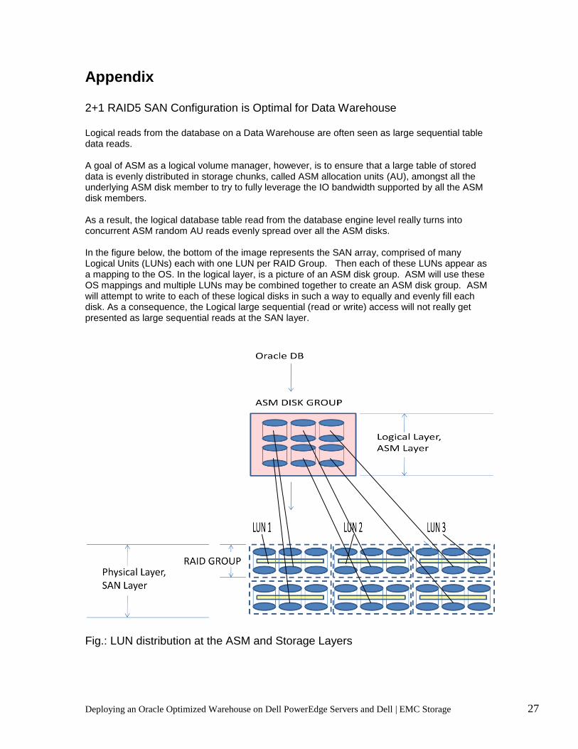
2+1 RAID5 SAN Configuration is Optimal for Data Warehouse Logical reads from the database on a Data Warehouse are often seen as large sequential table data reads. A goal of ASM as a logical volume manager, however, is to ensure that a large table of stored data is evenly distributed in storage chunks, called ASM allocation units (AU), amongst all the underlying ASM disk member to try to fully leverage the IO bandwidth supported by all the ASM disk members. As a result, the logical database table read from the database engine level really turns into concurrent ASM random AU reads evenly spread over all the ASM disks. In the figure below, the bottom of the image represents the SAN array, comprised of many Logical Units (LUNs) each with one LUN per RAID Group. Then each of these LUNs appear as a mapping to the OS. In the logical layer, is a picture of an ASM disk group. ASM will use these OS mappings and multiple LUNs may be combined together to create an ASM disk group. ASM will attempt to write to each of these logical disks in such a way to equally and evenly fill each disk. As a consequence, the Logical large sequential (read or write) access will not really get presented as large sequential reads at the SAN layer.
Fig.: LUN distribution at the ASM and Storage Layers

Deploying an Oracle Optimized Warehouse on Dell PowerEdge Servers and Dell | EMC Storage 28
The above picture shows a 256kb stripe read on two different RAID 5 configurations. If we seek to obtain a 512kb stripe, on two drives we can break this up into 2 256kb chunks of data. In contrast, on a RAID 5 4+1 we break each drives segment into 128kb.
After the first stripe has been read, the next 512KB of table data will not typically be serviced by the next storage stripe in the physical drives. Instead, the next 512KB of data requested from this ASM disk will typically be at a completely different LUN offset. Thus, the physical head on the disk must move to another section on the disk. While the drive head is seeking to a new position, it is not transferring any needed data. To achieve the most optimal MB/s of data read from the drive, it is therefore imperative that as much relevant data be read from the drives once the drive head is properly positioned. Hence, the 2+1R5, which results in 256KB to be read before the drive head moves again, will on average deliver more MB/s per drive compared to a 4+1R5 configuration. This causes narrow RAID implementations for Oracle running data warehouse implementations on ASM to be more optimal.