Embed Size (px)
Citation preview
910-0120-001 Rev B, October 2005
Tekelec EAGLE® 5 SAS - Release 34.0Database Administration - SS7
Table of Chapters
Table of Contents
List of Figures
List of Tables
List of Flowcharts
Chapter 1. Introduction
Chapter 2. Configuring Destination Tables
Chapter 3. SS7 Configuration
Appendix A. E1 Interface
Appendix B. T1 Interface
Appendix C. ATM Signaling Link Configuration
Appendix D. Reference Information
Index

Tekelec EAGLE® 5Signaling Application System
Release 34.0
Database Administration Manual - SS7910-0120-001 Revision B
October 2005
Copyright 2005 Tekelec.All Rights ReservedPrinted in U.S.A.
NoticeInformation in this documentation is subject to change without notice. Unauthorized use or copying of this documentation can result in civil or criminal penalties.
Any export of Tekelec products is subject to the export controls of the United States and the other countries where Tekelec has operations.
No part of this documentation may be reproduced or transmitted in any form or by any means, electronic or mechanical, including photocopying or recording, for any purpose without the express written permission of an authorized representative of Tekelec.
Other product names used herein are for identification purposes only, and may be trademarks of their respective companies.
TrademarksThe Tekelec logo, EAGLE, G-Flex, G-Port, IP7, IP7Edge, IP7 Secure Gateway, and TALI are registered trademarks of Tekelec, Inc. TekServer is a trademark of Tekelec, Inc. All other trademarks are the property of their respective owners.
PatentsThis product is covered by one or more of the following U.S. and foreign patents:
U.S. Patent Numbers:
5,008,929, 5,953,404, 6,167,129, 6,324,183, 6,327,350, 6,606,379, 6,639,981, 6,647,113, 6,662,017, 6,735,441, 6,745,041, 6,765,990, 6,795,546, 6,819,932, 6,836,477, 6,839,423, 6,885,872
Ordering InformationAdditional copies of this document can be ordered from:
Tekelec Network Signaling Group Attention: Central Logistics 5200 Paramount Parkway Morrisville, North Carolina, 27560
Or e-mail your request to [email protected].
910-0120-001 Rev B, October 2005 i
Table of Contents
Chapter 1. Introduction
Overview ............................................................................................. 1-2Manual Organization ........................................................................ 1-2Related Publications .......................................................................... 1-3Documentation Packaging and Updates ........................................ 1-8Documentation Admonishments .................................................... 1-8Customer Care Center ....................................................................... 1-8Emergency Response ......................................................................... 1-9Maintenance and Administration Subsystem .............................. 1-10Database Partitions .......................................................................... 1-11
Fixed Disk Drive ........................................................................ 1-12
Removable Cartridge ................................................................ 1-13List of Acronyms and Abbreviations ............................................ 1-14
Chapter 2. Configuring Destination Tables
Introduction ........................................................................................ 2-2Point Code Formats ........................................................................... 2-4
ANSI Point Codes ........................................................................ 2-4
ITU International Point Codes ................................................... 2-614-Bit ITU National Point Codes ............................................... 2-7
24-Bit ITU National Point Codes ............................................... 2-7Spare Point Codes ....................................................................... 2-7
Private Point Codes ..................................................................... 2-8Point Code Usage ........................................................................ 2-8
14-Bit ITU National Point Code Formats ...................................... 2-10Changing the Format of 14-Bit ITU National Point
Codes .................................................................................... 2-12
ITU National Duplicate Point Codes ............................................ 2-16Group Codes .............................................................................. 2-16
Normal Operation ..................................................................... 2-17C Linksets ................................................................................... 2-18
Receiving an ITU-National MSU on an ITU-International Linkset .................................................................................. 2-19
Existing ITU National Destinations ........................................ 2-20Interaction with Other Features .............................................. 2-20
Limitations .................................................................................. 2-22Changing the DPC Quantity .......................................................... 2-23

ii 910-0120-001 Rev B, October 2005
Table of Contents
Activating the ITU National and International Spare Point Code Support Feature ......................................................................... 2-42
Multiple Point Code Support .........................................................2-55Replacing Two STP Pairs with One Pair ................................2-56
Multiple Linksets between Two Nodes ..................................2-58Limitations .................................................................................. 2-62
Adding a Secondary Point Code ....................................................2-63Removing a Secondary Point Code ...............................................2-74Adding a Point Code to the Self-Identification of the
EAGLE 5 SAS ............................................................................. 2-81Changing the Self-Identification of the EAGLE 5 SAS ............... 2-90Cluster Routing and Management Diversity (CRMD) ............. 2-119
Exception Lists (X-lists) ...........................................................2-120Cluster Routing ........................................................................ 2-124
Compatibility with Non-Cluster Routing Nodes ............... 2-125Cluster Management and the ITU Network ........................2-125
Cluster Management When the Cluster Routing Feature is Turned Off ....................................................... 2-126
Cluster Routing and Management Diversity Rules ............ 2-126
Cluster Routing and Management Diversity Example .............................................................................. 2-128
Home Cluster Example ...........................................................2-132Nested Cluster Routing ................................................................. 2-135
Nested Clusters and Cluster Members .................................2-135Administration ......................................................................... 2-137
Nested Cluster Routing Rules of Operations ......................2-137Limitations of the Nested Cluster Routing Feature ............ 2-141
Adding a Cluster Point Code .......................................................2-142Changing the Attributes of a Cluster Point Code ......................2-161Network Routing ............................................................................ 2-174
Types of Routing Strategies Available .................................2-174Applications .............................................................................2-175
Route Availability ....................................................................2-176Point Code Availability ..........................................................2-176
Route Management ................................................................. 2-177Administration ......................................................................... 2-180
Adding a Network Routing Point Code .....................................2-181Adding a Destination Point Code ................................................2-191Removing a Destination Point Code ...........................................2-214

Table of Contents
910-0120-001 Rev B, October 2005 iii
Changing a Destination Point Code ............................................ 2-226Changing the Group Code Assigned to a 14-Bit ITU National
Point Code ................................................................................ 2-248
Chapter 3. SS7 Configuration
Introduction ........................................................................................ 3-3Enabling the Large System # Links Controlled Feature ............. 3-10Adding an SS7 Linkset .................................................................... 3-17
MTP Restart ................................................................................ 3-24
5-Bit to 8-Bit SLS Conversion ................................................... 3-26ITU SLS Enhancement .............................................................. 3-29
ITU TFR Procedures .................................................................. 3-33Sample Linkset Configuration ................................................. 3-35
Removing a Linkset Containing SS7 Signaling Links ................. 3-63Changing an SS7 Linkset ................................................................ 3-74Configuring an ITU Linkset with a Secondary Adjacent
Point Code (SAPC) .................................................................. 3-113Adding an SS7 Signaling Link ..................................................... 3-130
Example Signaling Link Configuration ................................ 3-134
Removing an SS7 Signaling Link ................................................. 3-145Adding a Route Containing an SS7 DPC .................................... 3-153Adding a Route Containing a Cluster Point Code .................... 3-164Adding a Route Containing an IPGWx Linkset ........................ 3-172Adding a Route Containing an X.25 DPC .................................. 3-181Removing a Route .......................................................................... 3-189Changing a Route ........................................................................... 3-206Changing Level 2 Timers .............................................................. 3-219Changing Level 3 Timers .............................................................. 3-222Changing a Signaling Link Test Message ................................... 3-228Configuring Circular Route Detection ........................................ 3-231Configuring the TFA/TFR Pacing Rate ...................................... 3-235Configuring the Frequency of RST Messages on Low Priority
Routes ........................................................................................ 3-238Adding Remote Loopback Points ................................................ 3-241Removing Remote Loopback Points ........................................... 3-247Changing Remote Loopback Points ............................................ 3-250Configuring the System for Random SLS Generation .............. 3-254Configuring the Options for the TDM Global Timing
Interface .................................................................................... 3-263Configuring the Restricted Linkset Option ................................ 3-269
iv 910-0120-001 Rev B, October 2005
Table of Contents
Configuring the Options for Handling TFCs on ITU-I and ITU-N Networks .............................................................. 3-276
Changing the HC MIM Temperature Alarm Thresholds ........3-279
Appendix A. E1 Interface
Introduction .......................................................................................A-2Configured as an E1 Card .........................................................A-5Configured as a Channel Card .................................................A-5
High Capacity Multi-Channel Interface Module (HC MIM) ..............................................................................A-6
Determining the Configuration .......................................................A-8External Interface Descriptions .................................................A-8E1 Cards Containing DIP Switches ..........................................A-8
Possible Configurations .............................................................A-9E1 Interface Configuration Procedures ........................................A-13Adding a LIM-E1 Card ...................................................................A-14Removing a LIM-E1 Card ..............................................................A-24Adding Channelized and non-Channel Bridged E1 Ports ........A-28Adding Channel Bridged E1 Ports ...............................................A-37Adding Unchannelized E1 Ports ...................................................A-45Removing the E1 Interface Parameters ........................................A-59Changing the Attributes of an E1 Port .........................................A-62Adding an E1 Signaling Link ........................................................A-77
Configuring Signaling Links on LIM-E1 Cards ...................A-80
Example Signaling Link Configuration .................................A-81
Appendix B. T1 Interface
Introduction ....................................................................................... B-2Configured as a T1 Card ............................................................ B-4Configured as a Channel Card ................................................. B-4
High Capacity Multi-Channel Interface Module (HC MIM) .............................................................................. B-4
Determining the Configuration ....................................................... B-7External Interface Descriptions ................................................. B-7Possible Configurations ............................................................. B-7
T1 Interface Configuration Procedures ........................................ B-10Adding a LIM-T1 Card ................................................................... B-11Removing a LIM-T1 Card .............................................................. B-20Adding the T1 Interface Parameters ............................................. B-24Removing the T1 Interface Parameters ........................................ B-33Changing the T1 Interface Parameters ......................................... B-36
Table of Contents
910-0120-001 Rev B, October 2005 v
Adding a T1 Signaling Link ...........................................................B-47Example Signaling Link Configuration ..................................B-50
Appendix C. ATM Signaling Link Configuration
Introduction ....................................................................................... C-1ATM Protocol Encapsulation .................................................... C-6
Overview of the ATM High-Speed Signaling Link LIM Operation ..................................................................................... C-8Applique .................................................................................... C-10
E1 Overview .............................................................................. C-12ATM Driver ............................................................................... C-15
E1 ATM Driver .......................................................................... C-16SSCOP ........................................................................................ C-16
SSCF ............................................................................................ C-17ATM and SAAL Layer Management Interfaces .................. C-18
ATM High-Speed Signaling Link Testing Capability ................ C-19Local Loopback Support .......................................................... C-19
Remote Loopback Support ...................................................... C-22Link Status Logging Capability .............................................. C-23
Large MSUs ...................................................................................... C-27Unsolicited Messages ..................................................................... C-27
Link Unavailability UAMs ...................................................... C-27
UIMs ........................................................................................... C-29ATM High-Speed Signaling Link Configuration ....................... C-30Adding a High-Speed LIM-ATM or an E1-ATM LIM ............... C-31Adding an ATM High-Speed Signaling Link ............................. C-34
Example Signaling Link Configuration ................................. C-37
Changing an ATM High-Speed Signaling Link Parameter Set ................................................................................................ C-50
Appendix D. Reference Information
Requirements for EAGLE 5 SASs Containing more than 700 Signaling Links ................................................. D-2
Determining the Number of High-Speed and Low-Speed Signaling Links ........................................................................... D-2
Index

vi 910-0120-001 Rev B, October 2005
List of Figures
Figure 1-1. Database Partitions ............................................................1-11
Figure 2-1. Mixed Network with ANSI, ITU-I, and ITU-N Nodes ...................................................................................................2-2
Figure 2-2. Network Example #1 .........................................................2-16
Figure 2-3. Network Example #2 .........................................................2-18
Figure 2-4. Network for Conversion ...................................................2-21
Figure 2-5. Replacing the First STP Pair ............................................. 2-56
Figure 2-6. Replacing a Second STP Pair ............................................2-58
Figure 2-7. Multiple Linkset Example ................................................2-59
Figure 2-8. Cluster Routing and Management Diversity ...............2-120
Figure 2-9. Cluster Management .......................................................2-129
Figure 2-10. Home Cluster Example .................................................2-132
Figure 2-11. Nested Cluster Routing Sample Configuration .................................................................................. 2-138
Figure 2-12. Example of Network Routing Reliability ................... 2-175
Figure 2-13. Potential Routing Network Failure .............................2-176
Figure 3-1. SS7 Database Relationships ................................................3-4
Figure 3-2. Complex Network with ANSI, ITU-I, and ITU-N Nodes ...................................................................................................3-8
Figure 3-3. Sample SS7 Network Configuration .................................3-9
Figure 3-4. ITU ISUP Routing Label with CIC ..................................3-29
Figure 3-5. Example of Bit Rotation ....................................................3-31
Figure 3-6. SLS creation Using “Other CIC Bit” ................................3-32
Figure 3-7. Random SLS Mapping to a Single Linkset ...................3-256
Figure A-1. LIM-E1 Block Diagram ......................................................A-2
Figure A-2. E1/T1 MIM Block Diagram ..............................................A-3
Figure A-3. HC MIM Block Diagram ...................................................A-4
Figure A-4. Channel Bridging ...............................................................A-6
Figure B-1. E1/T1 MIM Block Diagram .............................................. B-2
Figure B-2. HC MIM Block Diagram ................................................... B-3
Figure B-3. Channel Bridging ............................................................... B-5
Figure C-1. High-Speed Link Protocol Model for CCS Network Elements ............................................................................................. C-2

List of Figures
910-0120-001 Rev B, October 2005 vii
Figure C-2. ATM High-Speed Signaling Link Protocol Stack vs. Tekelec Implementation in the EAGLE 5 SAS .............. C-4
Figure C-3. Frame Formats for High-Speed and Low-Speed Signaling Link Protocol Stacks ........................................................ C-5
Figure C-4. ATM Protocol Encapsulation ........................................... C-7
Figure C-5. Functional Block Diagram of ATM High-Speed Signaling Link .................................................................................... C-9
Figure C-6. E1 Frame Structure .......................................................... C-12
Figure C-7. CRC-4 Multiframe Structure .......................................... C-14
Figure C-8. ATM Cell Mapping into E1 Frames .............................. C-15
Figure C-9. ANSI ATM High-Speed Signaling Link Loopback Support ............................................................................................. C-21
Figure C-10. E1 ATM High-Speed Signaling Link Loopback Support ............................................................................................. C-22
viii 910-0120-001 Rev B, October 2005
List of Tables
Table 2-1. Point Code Format .................................................................2-8
Table 2-2. 14-Bit ITU National Point Code Values ............................ 2-11
Table 2-3. Example Cluster Routing Information ........................... 2-129
Table 2-4. Home Cluster Routing Information ................................2-132
Table 2-5. Routing Models ..................................................................2-135
Table 2-6. Routing Table for Nested Cluster 5-5-* .......................... 2-139
Table 2-7. Routing Table for Full Point Code Member 5-5-1 .........2-139
Table 2-8. Example of Nested Cluster Routing Failure and Recovery Actions ............................................................................ 2-139
Table 2-9. Reception of an RSx Message ...........................................2-179
Table 2-10. Reception of an RCx Message ........................................2-180
Table 2-11. Destination Point Code and Alias Parameter Combinations .................................................................................. 2-194
Table 2-12. Sample Destination Point Code Table Configuration .................................................................................. 2-196
Table 2-13. Destination Point Code and Alias Parameter Combinations .................................................................................. 2-229
Table 3-1. SS7 Signaling Link Card Types and Applications ............3-5
Table 3-2. Actions of the National Spare for Network Indicator Feature ............................................................................................... 3-19
Table 3-3. MTP Restart Signaling Link Alignment Delay ................3-25
Table 3-4. Signaling Link Selector (SLS) Conversion (ANSI Linksets Only) ................................................................................... 3-27
Table 3-5. Route Management Messages Sent on Status Transition ........................................................................................... 3-34
Table 3-6. Linkset Configuration Table ..............................................3-35
Table 3-7. Actions of the National Spare for Network Indicator Feature ............................................................................................... 3-77
Table 3-8. Secondary Adjacent Point Code Configuration Table ................................................................................................. 3-114
Table 3-9. L2TSET Parameter Values ................................................3-131
Table 3-10. SS7 Signaling Link Parameter Combinations ..............3-133
Table 3-11. Low-Speed Signaling Link Configuration Table ........ 3-134
Table 3-12. Level 2 Timer Sets ............................................................3-219
List of Tables
910-0120-001 Rev B, October 2005 ix
Table 3-13. Level 2 Timer Values ....................................................... 3-219
Table 3-14. Loopback Point Configuration Table ........................... 3-242
Table 3-15. Failure Scenarios for a 32-Link Combined Linkset ............................................................................................. 3-257
Table A-1. Functional Overview of the E1 and Channel Card ........ A-5
Table A-2. Channel Bridging E1 Port Pairing ..................................... A-7
Table A-3. E1 Signaling Link Configuration Form .......................... A-12
Table A-4. E1 Card Part Numbers ...................................................... A-14
Table A-5. HC MIM Card Locations .................................................. A-14
Table A-6. Card Removal Procedures ............................................... A-16
Table A-7. Maximum Number of E1 Ports .......................................A-30
Table A-8. E1 Interface Parameter Combinations ............................ A-31
Table A-9. Channel Bridging Ports .................................................... A-38
Table A-10. Channel Bridged E1 Port Combinations ...................... A-41
Table A-11. Unchannelized E1 Signaling Link Quantity Part Numbers ........................................................................................... A-50
Table A-12. Unchannelized E1 Port Parameter Combinations ................................................................................... A-51
Table A-13. Channel Bridging Ports .................................................. A-63
Table A-14. E1 Interface Parameter Combinations .......................... A-67
Table A-15. L2TSET Parameter Values .............................................. A-78
Table A-16. E1 Signaling Link Configuration Table ........................ A-81
Table A-17. Link Parameter Values ................................................... A-87
Table B-1. Functional Overview of the T1 and Channel Card ......................................................................................................B-4
Table B-2. Channel Bridging T1 Port Pairing ......................................B-5
Table B-3. T1 Signaling Link Configuration Form ..............................B-9
Table B-4. T1 Card Part Numbers .......................................................B-11
Table B-5. HC MIM Card Locations ....................................................B-11
Table B-6. Card Removal Procedures .................................................B-13
Table B-7. Channel Bridging Ports ......................................................B-24
Table B-8. T1 Interface Parameter Combinations .............................B-27
Table B-9. Channel Bridging Ports ......................................................B-36
Table B-10. T1 Interface Parameter Combinations ...........................B-39
Table B-11. L2TSET Parameter Values ...............................................B-48
Table B-12. T1 Signaling Link Configuration Table .........................B-50
Table B-13. Link Parameter Values .....................................................B-55
x 910-0120-001 Rev B, October 2005
List of Tables
Table C-1. Link Proving Differences Between ITU and ANSI .................................................................................................. C-17
Table C-2. ATM High-Speed Signaling Link Loopback Support ............................................................................................. C-20
Table C-3. High-Speed Signaling Link vs. Low-Speed Signaling Link Unavailability Reasons by Priority ...................................... C-23
Table C-4. High-Speed Signaling Link State Transition Alignment Events ............................................................................ C-25
Table C-5. High-Speed Signaling Link Transmitted/Received Alignment PDUs ............................................................................. C-25
Table C-6. High-Speed Signaling Link Special Level 1 Alignment Events ................................................................................................ C-26
Table C-7. Signaling Link Unsolicited Alarm Messages ................. C-28
Table C-8. Table 5 : Loopback Test UIMs .......................................... C-29
Table C-9. ATM High-Speed LIM Card Type and Card Application Combinations ............................................................. C-31
Table C-10. Example Card Configuration ......................................... C-31
Table C-11. ATM Signaling Link Cable Lengths .............................. C-35
Table C-12. ATM High-Speed Signaling Link Parameter Combinations ................................................................................... C-36
Table C-13. ANSI High-Speed ATM Signaling Link Configuration Table ........................................................................ C-37
Table C-14. E1 High-Speed ATM Signaling Link Configuration Table ........................................................................ C-37
Table D-1. Number of High-Speed and Low-Speed Links Supported at 100% Traffic ................................................................D-3

910-0120-001 Rev B, October 2005 xi
List of Flowcharts
Flowchart 2-1. Changing the Format of an ITU National Point Code ......................................................................................... 2-13
Flowchart 2-2. Changing the DPC Quantity ...................................... 2-35Flowchart 2-3. Activating the ITU National and International
Spare Point Code Support Feature ................................................ 2-51Flowchart 2-4. Adding a Secondary Point Code ............................... 2-70Flowchart 2-5. Removing a Secondary Point Code .......................... 2-78Flowchart 2-6. Adding a Point Code to the Self-Identification
of the EAGLE 5 SAS ......................................................................... 2-87Flowchart 2-7. Changing the Self-Identification of the
System .............................................................................................. 2-108Flowchart 2-8. Adding a Cluster Point Code .................................. 2-155Flowchart 2-9. Changing the Attributes of a Cluster Point
Code ................................................................................................. 2-169Flowchart 2-10. Adding a Network Routing Point Code .............. 2-188Flowchart 2-11. Adding a Destination Point Code ......................... 2-206Flowchart 2-12. Removing a Destination Point Code .................... 2-221Flowchart 2-13. Changing a Destination Point Code ..................... 2-239Flowchart 2-14. Changing the Group Code Assigned to a
14-Bit ITU National Point Code ................................................... 2-251Flowchart 3-1. Enabling the Large System # Links Controlled
Feature ............................................................................................... 3-14Flowchart 3-2. Adding an SS7 Linkset ................................................ 3-52Flowchart 3-3. Removing a Linkset Containing SS7 Signaling
Links ................................................................................................... 3-72Flowchart 3-4. Changing an SS7 Linkset ............................................ 3-99Flowchart 3-5. Configuring an ITU Linkset with a Secondary
Adjacent Point Code (SAPC) ........................................................ 3-125Flowchart 3-6. Adding an SS7 Signaling Link ................................. 3-142Flowchart 3-7. Removing an SS7 Signaling Link ............................ 3-151Flowchart 3-8. Adding a Route Containing an SS7 DPC ............... 3-161Flowchart 3-9. Adding a Route Containing a Cluster Point
Code ................................................................................................. 3-170Flowchart 3-10. Adding a Route Containing an IPGWx
Linkset ............................................................................................. 3-178Flowchart 3-11. Adding a Route Containing an X.25 DPC ........... 3-187Flowchart 3-12. Removing a Route ................................................... 3-199Flowchart 3-13. Changing a Route .................................................... 3-215
xii 910-0120-001 Rev B, October 2005
List of Flowcharts
Flowchart 3-14. Changing the Level 2 Timers .................................3-221Flowchart 3-15. Changing the Level 3 Timers .................................3-227Flowchart 3-16. Changing a Signaling Link Test Message ............ 3-230Flowchart 3-17. Configuring the System to Detect Circular
Routing ............................................................................................ 3-234Flowchart 3-18. Configuring the TFA/TFR Pacing Rate ...............3-237Flowchart 3-19. Configuring the Frequency of RST Messages on
Low Priority Routes ....................................................................... 3-240Flowchart 3-20. Adding Remote Loopback Points .........................3-246Flowchart 3-21. Removing Remote Loopback Points .....................3-249Flowchart 3-22. Changing Remote Loopback Points ......................3-253Flowchart 3-23. Random SLS Mapping to a Combined
Linkset .............................................................................................. 3-255Flowchart 3-24. Configuring the System for Random SLS
Generation ....................................................................................... 3-261Flowchart 3-25. Configuring the Options for the TDM Global
Timing Interface .............................................................................3-267Flowchart 3-26. Configuring the Restricted Linkset Option ......... 3-274Flowchart 3-27. Configuring the Options for Handling TFCs
on ITU-I and ITU-N Networks ..................................................... 3-278Flowchart 3-28. Changing the HC MIM Temperature Alarm
Thresholds ....................................................................................... 3-282Flowchart A-1. Adding a LIM-E1 Card .............................................A-20Flowchart A-2. Removing a LIM-E1 Card ........................................A-27Flowchart A-3. Adding Channelized and non-Channel
Bridged E1 Ports ..............................................................................A-33Flowchart A-4. Removing the E1 Interface Parameters ..................A-61Flowchart A-5. Changing the Attributes of an E1 Port ...................A-69Flowchart A-6. Adding an E1 Signaling Link ...................................A-92Flowchart B-1. Adding a LIM-T1 Card .............................................. B-16Flowchart B-2. Removing a LIM-T1 Card ......................................... B-23Flowchart B-3. Adding the T1 Interface Parameters ....................... B-29Flowchart B-4. Removing the T1 Interface Parameters ................... B-35Flowchart B-5. Changing the T1 Interface Parameters .................... B-41Flowchart B-6. Adding a T1 Signaling Link ...................................... B-58Flowchart C-1. Adding a High-Speed LIM-ATM or an E1-ATM
LIM .................................................................................................... C-33Flowchart C-2. Adding an ATM High-Speed Signaling Link ........ C-46Flowchart C-3. Changing an ATM High-Speed Signaling Link
Parameter Set ................................................................................... C-56

910-0120-001 Rev B, October 2005 1-1
1
Introduction
Overview .................................................................................................... 1-2
Manual Organization ................................................................................ 1-2
Related Publications.................................................................................. 1-3
Documentation Packaging and Updates................................................ 1-8
Documentation Admonishments ............................................................ 1-8
Customer Care Center .............................................................................. 1-8
Emergency Response ................................................................................ 1-9
Maintenance and Administration Subsystem ..................................... 1-10
Database Partitions.................................................................................. 1-11
Fixed Disk Drive................................................................................ 1-12
Removable Cartridge........................................................................ 1-13
List of Acronyms and Abbreviations.................................................... 1-14
1-2 910-0120-001 Rev B, October 2005
Introduction
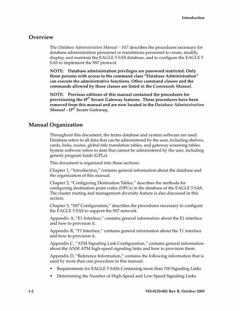
Overview
The Database Administration Manual – SS7 describes the procedures necessary for database administration personnel or translations personnel to create, modify, display, and maintain the EAGLE 5 SAS database, and to configure the EAGLE 5 SAS to implement the SS7 protocol.
NOTE: Database administration privileges are password restricted. Only those persons with access to the command class “Database Administration” can execute the administrative functions. Other command classes and the commands allowed by those classes are listed in the Commands Manual.
NOTE: Previous editions of this manual contained the procedures for provisioning the IP7 Secure Gateway features. These procedures have been removed from this manual and are now located in the Database Administration Manual - IP7 Secure Gateway.
Manual Organization
Throughout this document, the terms database and system software are used. Database refers to all data that can be administered by the user, including shelves, cards, links, routes, global title translation tables, and gateway screening tables. System software refers to data that cannot be administered by the user, including generic program loads (GPLs).
This document is organized into these sections:
Chapter 1, “Introduction,” contains general information about the database and the organization of this manual.
Chapter 2, “Configuring Destination Tables,” describes the methods for configuring destination point codes (DPCs) in the database of the EAGLE 5 SAS. The cluster routing and management diversity feature is also discussed in this section.
Chapter 3, “SS7 Configuration,” describes the procedures necessary to configure the EAGLE 5 SAS to support the SS7 network.
Appendix A, “E1 Interface,” contains general information about the E1 interface and how to provision it.
Appendix B, “T1 Interface,” contains general information about the T1 interface and how to provision it.
Appendix C, “ATM Signaling Link Configuration,” contains general information about the ANSI ATM high-speed signaling links and how to provision them.
Appendix D, “Reference Information,” contains the following information that is used by more than one procedure in this manual:
• Requirements for EAGLE 5 SASs Containing more than 700 Signaling Links
• Determining the Number of High-Speed and Low-Speed Signaling Links

Introduction
910-0120-001 Rev B, October 2005 1-3
Related Publications
The Database Administration Manual – SS7 is part of the EAGLE 5 SAS documentation set and may refer to one or more of the following manuals:
• The Commands Manual contains procedures for logging into or out of the EAGLE 5 SAS, a general description of the terminals, printers, the disk drive used on the system, and a description of all the commands used in the system.
• The Commands Pocket Guide is an abridged version of the Commands Manual. It contains all commands and parameters, and it shows the command-parameter syntax.
• The Commands Quick Reference Guide contains an alphabetical listing of the commands and parameters. The guide is sized to fit a shirt-pocket.
• The Commands Error Recovery Manual contains the procedures to resolve error message conditions generated by the commands in the Commands Manual. These error messages are presented in numerical order.
• The Database Administration Manual – Features contains procedural information required to configure the EAGLE 5 SAS to implement these features:
– X.25 Gateway
– STP LAN
– Database Transport Access
– GSM MAP Screening
– EAGLE 5 SAS Support for Integrated Sentinel
• The Database Administration Manual - Gateway Screening contains a description of the Gateway Screening (GWS) feature and the procedures necessary to configure the EAGLE 5 SAS to implement this feature.
• The Database Administration Manual – Global Title Translation contains procedural information required to configure an EAGLE 5 SAS to implement these features:
– Global Title Translation
– Enhanced Global Title Translation
– Variable Length Global Title Translation
– Interim Global Title Modification
– Intermediate GTT Load Sharing
– ANSI-ITU-China SCCP Conversion

1-4 910-0120-001 Rev B, October 2005
Introduction
• The Database Administration Manual - IP7 Secure Gateway contains procedural information required to configure the EAGLE 5 SAS to implement the SS7-IP Gateway.
• The Database Administration Manual – SEAS contains the EAGLE 5 SAS configuration procedures that can be performed from the Signaling Engineering and Administration Center (SEAC) or a Signaling Network Control Center (SNCC). Each procedure includes a brief description of the procedure, a flowchart showing the steps required, a list of any EAGLE 5 SAS commands that may be required for the procedure but that are not supported by SEAS, and a reference to optional procedure-related information, which can be found in one of these manuals:
– Database Administration Manual – Gateway Screening
– Database Administration Manual – Global Title Translation
– Database Administration Manual – SS7
• The Database Administration Manual – SS7 contains procedural information required to configure an EAGLE 5 SAS to implement the SS7 protocol.
• The Database Administration Manual – System Management contains procedural information required to manage the EAGLE 5 SAS database and GPLs, and to configure basic system requirements such as user names and passwords, system-wide security requirements, and terminal configurations.
• The Dimensioning Guide for EPAP Advanced DB Features is used to provide EPAP planning and dimensioning information. This manual is used by Tekelec personnel and EAGLE 5 SAS customers to aid in the sale, planning, implementation, deployment, and upgrade of EAGLE 5 SAS systems equipped with one of the EAGLE 5 SAS EPAP Advanced Database (EADB) Features.
• The ELAP Administration Manual defines the user interface to the EAGLE 5 SAS LNP Application Processor on the MPS/ELAP platform. The manual defines the methods for accessing the user interface, menus, screens available to the user and describes their impact. It provides the syntax and semantics of user input, and defines the output the user receives, including information and error messages, alarms, and status.
• The EPAP Administration Manual describes how to administer the EAGLE 5 SAS Provisioning Application Processor on the MPS/EPAP platform. The manual defines the methods for accessing the user interface, menus, and screens available to the user and describes their impact. It provides the syntax and semantics of user input and defines the output the user receives, including messages, alarms, and status.
• The Feature Manual - EIR provides instructions and information on how to install, use, and maintain the EIR feature on the Multi-Purpose Server (MPS) platform of the EAGLE 5 SAS. The feature provides network operators with
Introduction
910-0120-001 Rev B, October 2005 1-5
the capability to prevent stolen or disallowed GSM mobile handsets from accessing the network.
• The Feature Manual - G-Flex C7 Relay provides an overview of a feature supporting the efficient management of Home Location Registers in various networks. This manual gives the instructions and information on how to install, use, and maintain the G-Flex feature on the Multi-Purpose Server (MPS) platform of the EAGLE 5 SAS.
• The Feature Manual - G-Port provides an overview of a feature providing the capability for mobile subscribers to change the GSM subscription network within a portability cluster while retaining their original MSISDNs. This manual gives the instructions and information on how to install, use, and maintain the G-Port feature on the Multi-Purpose Server (MPS) platform of the EAGLE 5 SAS.
• The Feature Manual - INP provides the user with information and instructions on how to implement, utilize, and maintain the INAP-based Number Portability (INP) feature on the Multi-Purpose Server (MPS) platform of the EAGLE 5 SAS.
• The FTP-Based Table Retrieve Application (FTRA) User Guide describes how to set up and use a PC to serve as the offline application for the EAGLE 5 SAS FTP Retrieve and Replace feature.
• The Hardware Manual - EAGLE 5 SAS contains hardware descriptions and specifications of Tekelec’s signaling products. These include the EAGLE 5 SAS, OEM-based products such as the ASi 4000 Service Control Point (SCP), the Netra-based Multi-Purpose Server (MPS), and the Integrated Sentinel with Extended Services Platform (ESP) subassembly.
• The Hardware Manual provides an overview of each system and its subsystems, details of standard and optional hardware components in each system, and basic site engineering. Refer to this manual to obtain a basic understanding of each type of system and its related hardware, to locate detailed information about hardware components used in a particular release, and to help configure a site for use with the system hardware.
• The Hardware Manual - Tekelec 1000 Application Server provides general specifications and a description of the Tekelec 1000 Applications Server (T1000 AS). This manual also includes site preparation, environmental and other requirements, procedures to physically install the T1000 AS, and troubleshooting and repair of Field Replaceable Units (FRUs).
• The Hardware Manual - Tekelec 1100 Application Server provides general specifications and a description of the Tekelec 1100 Applications Server (T1000 AS). This manual also includes site preparation, environmental and other requirements, procedures to physically install the T1100 AS, and troubleshooting and repair of Field Replaceable Units (FRUs).
• The Installation Manual - EAGLE 5 SAS contains cabling requirements, schematics, and procedures for installing the EAGLE 5 SAS along with LEDs,

1-6 910-0120-001 Rev B, October 2005
Introduction
Connectors, Cables, and Power Cords to Peripherals. Refer to this manual to install components or the complete systems.
• The Installation Manual - Integrated Applications provides the installation information for integrated applications such as EPAP 4.0 or earlier (Netra-based Multi-Purpose Server (MPS) platform) and Sentinel. The manual includes information about frame floors and shelves, LEDs, connectors, cables, and power cords to peripherals. Refer to this manual to install components or the complete systems.
• The LNP Database Synchronization Manual - LSMS with EAGLE 5 SAS describes how to keep the LNP databases at the LSMS and at the network element (the EAGLE 5 SAS is a network element) synchronized through the use of resynchronization, audits and reconciles, and bulk loads. This manual is contained in both the LSMS documentation set and in the EAGLE 5 SAS documentation set.
• The LNP Feature Activation Guide contains procedural information required to configure the EAGLE 5 SAS for the LNP feature and to implement these parts of the LNP feature on the EAGLE 5 SAS:
– LNP services
– LNP options
– LNP subsystem application
– Automatic call gapping
– Triggerless LNP feature
– Increasing the LRN and NPANXX Quantities on the EAGLE 5 SAS
– Activating and Deactivating the LNP Short Message Service (SMS) feature
• The Maintenance Manual contains procedural information required for maintaining the EAGLE 5 SAS and the card removal and replacement procedures. The Maintenance Manual provides preventive and corrective maintenance procedures used in maintaining the different systems.
• The Maintenance Pocket Guide is an abridged version of the Maintenance Manual and contains all the corrective maintenance procedures used in maintaining the EAGLE 5 SAS.
• The Maintenance Emergency Recovery Pocket Guide is an abridged version of the Maintenance Manual and contains the corrective maintenance procedures for critical and major alarms generated on the EAGLE 5 SAS.
• The MPS Platform Software and Maintenance Manual - EAGLE 5 SAS with Tekelec 1000 Application Server describes the platform software for the Multi-Purpose Server (MPS) based on the Tekelec 1000 Application Server (T1000 AS) and describes how to perform preventive and corrective maintenance for the T1000 AS-based MPS. This manual should be used with the EPAP-based applications (EIR, G-Port, G-Flex, and INP).

Introduction
910-0120-001 Rev B, October 2005 1-7
• The MPS Platform Software and Maintenance Manual - EAGLE 5 SAS with Tekelec 1100 Application Server describes the platform software for the Multi-Purpose Server (MPS) based on the Tekelec 1100 Application Server (T1100 AS) and describes how to perform preventive and corrective maintenance for the T1100 AS-based MPS. This manual should be used with the ELAP-based application (LNP).
• The Provisioning Database Interface Manual defines the programming interface that populates the Provisioning Database (PDB) for the EAGLE 5 SAS features supported on the MPS/EPAP platform. The manual defines the provisioning messages, usage rules, and informational and error messages of the interface. The customer uses the PDBI interface information to write his own client application to communicate with the MPS/EPAP platform.
• The Previously Released Features Manual summarizes the features of previous EAGLE, EAGLE 5 SAS, and IP7 Secure Gateway releases, and it identifies the release number of their introduction.
• The Release Documentation contains the following documents for a specific release of the system:
– Feature Notice - Describes the features contained in the specified release. The Feature Notice also provides the hardware baseline for the specified release, describes the customer documentation set, provides information about customer training, and explains how to access the Customer Support website.
– Release Notice - Describes the changes made to the system during the lifecycle of a release. The Release Notice includes Generic Program Loads (GPLs), a list of PRs resolved in a build, and all known PRs.
NOTE: The Release Notice is maintained solely on Tekelec’s Customer Support site to provide you with instant access to the most up-to-date release information.
– System Overview - Provides high-level information on SS7, the IP7 Secure Gateway, system architecture, LNP, and EOAP.
– Master Glossary - Contains an alphabetical listing of terms, acronyms, and abbreviations relevant to the system.
– Master Index - Lists all index entries used throughout the documentation set.
• The System Manual – EOAP describes the Embedded Operations Support System Application Processor (EOAP) and provides the user with procedures on how to implement the EOAP, replace EOAP-related hardware, device testing, and basic troubleshooting information.

1-8 910-0120-001 Rev B, October 2005
Introduction
Documentation Packaging and Updates
Customer documentation is updated whenever significant changes that affect EAGLE 5 SAS operation or configuration are made.
The document part number is shown on the title page along with the current revision of the document, the date of publication, and, if applicable, the software release that the document covers. The bottom of each page contains the document part number and the date of publication.
Documentation Admonishments
Admonishments are icons and text that may appear in this and other EAGLE 5 SAS manuals that alert the reader to assure personal safety, to minimize possible service interruptions, and to warn of the potential for equipment damage.
Following are the admonishments, listed in descending order of priority.
Customer Care Center
The Customer Care Center offers a point of contact through which customers can receive support for problems that may be encountered during the use of Tekelec’s products. The Customer Care Center is staffed with highly trained engineers to provide solutions to your technical questions and issues seven days a week, twenty-four hours a day. A variety of service programs are available through the Customer Care Center to maximize the performance of Tekelec products that meet and exceed customer needs.
To receive technical assistance, call the Customer Care Center at one of the following locations:
• Tekelec, UK
Phone: +44 1784 467 804Fax: +44 1784 477 120Email: [email protected]
DANGER:
(This icon and text indicate the possibility of personal injury.)
CAUTION:
(This icon and text indicate the possibility of service interruption.)
WARNING:
(This icon and text indicate the possibility of equipment damage.)

Introduction
910-0120-001 Rev B, October 2005 1-9
• Tekelec, USA
Phone (within the continental US) 888-367-8552 (888-FOR-TKLC)(outside the continental US) +1 919-460-2150.
Email: [email protected].
When your call is received, the Customer Care Center issues a Customer Service Report (CSR). Each CSR includes an individual tracking number. When a CSR is issued, the Customer Care Center determines the classification of the trouble. The CSR contains the serial number of the system, problem symptoms, and messages. The Customer Care Center assigns the CSR to a primary engineer, who will work to solve the problem. The Customer Care Center closes the CSR when the problem is resolved.
If a critical problem exists, the Customer Care Center initiates emergency procedures (see the following topic, “Emergency Response”).
Emergency Response
If a critical service situation occurs, the Customer Care Center offers emergency response twenty-four hours a day, seven days a week. The emergency response provides immediate coverage, automatic escalation, and other features to ensure a rapid resolution to the problem.
A critical situation is defined as an EAGLE 5 SAS or LSMS problem that severely affects service, traffic, or maintenance capabilities, and requires immediate corrective action. Critical problems affect service or system operation, resulting in:
• Failure in the system that prevents transaction processing
• Reduction in EAGLE 5 SAS capacity or in EAGLE 5 SAS traffic-handling capability
• Inability to restart the EAGLE 5 SAS
• Corruption of the database
• Inability to perform maintenance or recovery operations
• Inability to provide any required critical or major trouble notification
• Any other problem severely affecting service, capacity, traffic, and billing. Maintenance capabilities may be defined as critical by prior discussion and agreement with the Customer Care Center.
1-10 910-0120-001 Rev B, October 2005
Introduction
Maintenance and Administration Subsystem
The maintenance and administration subsystem consists of two processors, MASP (maintenance and administration subsystem processor) A and MASP B.
Each MASP is made up of two cards, the GPSM-II card (general purpose service module) and the TDM (terminal disk module).
The GPSM-II card contains the communications processor and applications processor and provides connections to the IMT bus. The GPSM-II controls the maintenance and database administration activity.
The TDM contains the fixed disk drive, the terminal processor for the 16 serial I/O ports and interfaces to the MDAL (maintenance disk and alarm) card which contains the removable cartridge drive and alarm logic. There is only one MDAL card in the maintenance and administration subsystem and it is shared between the two MASPs.
The procedures in the Database Administration Manual – SS7 refer to the terms MASP and MDAL. The database commands, such as rept-stat-db, refer to the MASP because the MASP controls the input to the TDM and MDAL, and output from the TDM and MDAL. The MDAL is only referred to when inserting or removing the removable cartridge because the removable cartridge drive resides on the MDAL.
For more information on these cards, go to the Hardware Manual - EAGLE 5 SAS.
Introduction
910-0120-001 Rev B, October 2005 1-11
Database Partitions
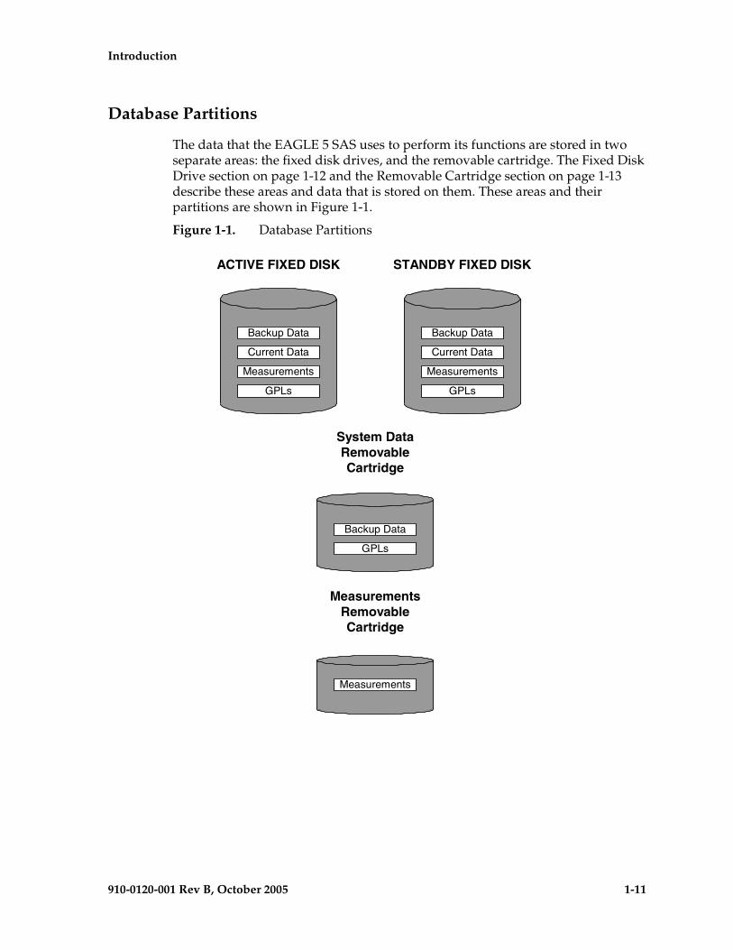
The data that the EAGLE 5 SAS uses to perform its functions are stored in two separate areas: the fixed disk drives, and the removable cartridge. The Fixed Disk Drive section on page 1-12 and the Removable Cartridge section on page 1-13 describe these areas and data that is stored on them. These areas and their partitions are shown in Figure 1-1.
Figure 1-1. Database Partitions
ACTIVE FIXED DISK STANDBY FIXED DISK
System DataRemovableCartridge
MeasurementsRemovableCartridge
Backup Data
Current Data
Measurements
GPLs
Backup Data
Current Data
Measurements
GPLs
Backup Data
GPLs
Measurements

1-12 910-0120-001 Rev B, October 2005
Introduction
Fixed Disk Drive
There are two fixed disk drives on the EAGLE 5 SAS. The fixed disk drives contain the “master” set of data and programs for the EAGLE 5 SAS. The two fixed disk drives are located on the terminal disk modules (TDMs). Both disks have the same files. The data stored on the fixed disks is partially replicated on the various cards in the EAGLE 5 SAS. Changes made during database administration sessions are sent to the appropriate cards.
The data on the fixed disks can be viewed as four partitions.
• Current partition
• Backup partition
• Measurements partition
• Generic program loads (GPLs) partition
The data which can be administered by users is stored in two partitions on the fixed disk, a current database partition which has the tables which are changed by on-line administration, and a backup database partition which is a user-controlled copy of the current partition.
All of the on-line data administration commands effect the data in the current partition. The purpose of the backup partition is to provide the users with a means of rapidly restoring the database to a known good state if there has been a problem while changing the current partition.
A full set of GPLs is stored on the fixed disk in the GPL partition. There is an approved GPL and a trial GPL for each type of GPL in this set and a utility GPL, which has only an approved version. Copies of these GPLs are downloaded to the EAGLE 5 SAS cards. The GPL provides each card with its functionality. For example, the ss7ansi GPL provides MTP functionality for link interface modules (LIMs).
Measurement tables are organized as a single partition on the fixed disk. These tables are used as holding areas for the measurement counts.

Introduction
910-0120-001 Rev B, October 2005 1-13
Removable Cartridge
A removable cartridge is used for two purposes.
• To hold an off-line backup copy of the administered data and system GPLs
• To hold a copy of the measurement tables
Because of the size of the data stored on the fixed disk drives on the TDMs, a single removable cartridge cannot store all of the data in the database, GPL, and measurements partitions.
To use a removable cartridge to hold the system data, it must be formatted for system data. To use a removable cartridge to hold measurements data, it must be formatted for measurements data. The EAGLE 5 SAS provides the user the ability to format a removable cartridge for either of these purposes. A removable cartridge can be formatted on the EAGLE 5 SAS by using the format-disk command. More information on the format-disk command can be found in the Commands Manual. More information on the removable cartridge drive can be found in the Hardware Manual - EAGLE 5 SAS.
The removable cartridge drive is located on the MDAL card in card location 1117.
Additional and preformatted removable cartridges are available from the Customer Care Center.
1-14 910-0120-001 Rev B, October 2005
Introduction
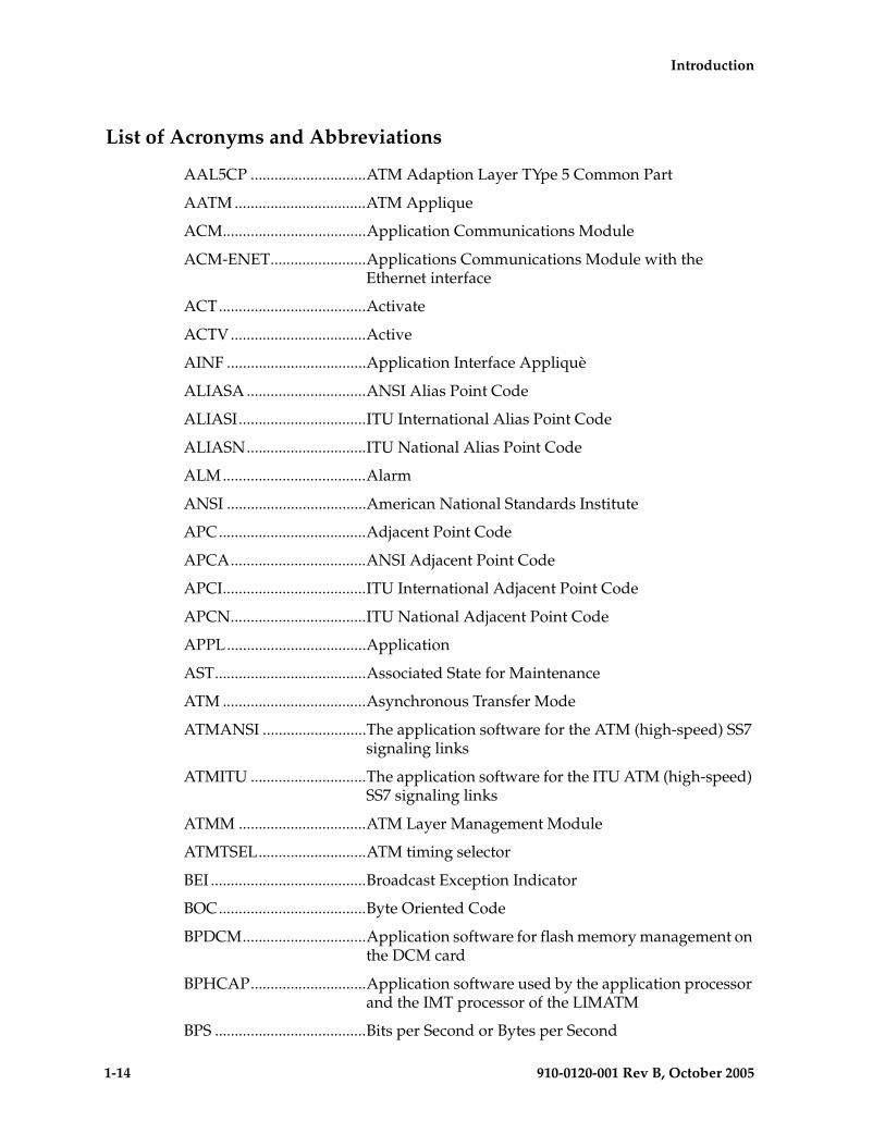
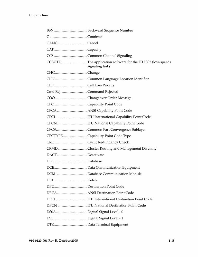
List of Acronyms and Abbreviations
AAL5CP .............................ATM Adaption Layer TYpe 5 Common Part
AATM .................................ATM Applique
ACM....................................Application Communications Module
ACM-ENET........................Applications Communications Module with the Ethernet interface
ACT.....................................Activate
ACTV..................................Active
AINF ...................................Application Interface Appliquè
ALIASA ..............................ANSI Alias Point Code
ALIASI................................ITU International Alias Point Code
ALIASN..............................ITU National Alias Point Code
ALM....................................Alarm
ANSI ...................................American National Standards Institute
APC.....................................Adjacent Point Code
APCA..................................ANSI Adjacent Point Code
APCI....................................ITU International Adjacent Point Code
APCN..................................ITU National Adjacent Point Code
APPL...................................Application
AST......................................Associated State for Maintenance
ATM ....................................Asynchronous Transfer Mode
ATMANSI ..........................The application software for the ATM (high-speed) SS7 signaling links
ATMITU .............................The application software for the ITU ATM (high-speed) SS7 signaling links
ATMM ................................ATM Layer Management Module
ATMTSEL...........................ATM timing selector
BEI .......................................Broadcast Exception Indicator
BOC.....................................Byte Oriented Code
BPDCM...............................Application software for flash memory management on the DCM card
BPHCAP.............................Application software used by the application processor and the IMT processor of the LIMATM
BPS ......................................Bits per Second or Bytes per Second
Introduction
910-0120-001 Rev B, October 2005 1-15
BSN .....................................Backward Sequence Number
C ..........................................Continue
CANC .................................Cancel
CAP.....................................Capacity
CCS .....................................Common Channel Signaling
CCS7ITU ............................The application software for the ITU SS7 (low-speed) signaling links
CHG....................................Change
CLLI ....................................Common Language Location Identifier
CLP .....................................Cell Loss Priority
Cmd Rej..............................Command Rejected
COO....................................Changeover Order Message
CPC .....................................Capability Point Code
CPCA..................................ANSI Capability Point Code
CPCI....................................ITU International Capability Point Code
CPCN..................................ITU National Capability Point Code
CPCS...................................Common Part Convergence Sublayer
CPCTYPE ...........................Capability Point Code Type
CRC.....................................Cyclic Redundancy Check
CRMD.................................Cluster Routing and Management Diversity
DACT..................................Deactivate
DB........................................Database
DCE.....................................Data Communication Equipment
DCM ..................................Database Communication Module
DLT .....................................Delete
DPC.....................................Destination Point Code
DPCA..................................ANSI Destination Point Code
DPCI ...................................ITU International Destination Point Code
DPCN .................................ITU National Destination Point Code
DS0A...................................Digital Signal Level - 0
DS1......................................Digital Signal Level - 1
DTE .....................................Data Terminal Equipment

1-16 910-0120-001 Rev B, October 2005
Introduction
E1.........................................European equivalent of the North American 1.544 Mbps T1 (Trunk Level 1) except that E1 carries information at 2.048 Mbps.
ECM ....................................Error Correction Method
EIR.......................................Equipment Identity Register
ELEI.....................................Exception List Exclusion Indicator
EMDC .................................Element Measurement and Data Collection
ENT .....................................Enter
EOAM.................................Enhanced Operations, Administration, and Maintenance
FAK .....................................Feature Access Key
FAS ......................................Frame Alignment Signal
FC ........................................Flow control
FE.........................................Far End
FIB .......................................Forward Indicator Bit
FISU ...................................Fill In Signal Unit
FPC......................................Provisioned full point code entry
FPCA...................................Full Point Code entry
FTA ......................................File Transfer Area
FTP ......................................File Transfer Protocol
GLS......................................Gateway Loading Services – Application software for the gateway screening loading services
GPL .....................................Generic Program Load
GPSM..................................General Purpose Service Module
GTT .....................................Global Title Translation
GWS ....................................Gateway Screening
GWSA.................................Gateway Screening Application
GWSD .................................Gateway Screening Message Discard
GWSM ................................Gateway Screening Mode
HC MIM .............................High-Capacity Multi-Channel Interface Module
HEC.....................................Header Error Control
HIPR ...................................High-Speed IMT Packet Router
I/O ......................................Input/Output
IAM .....................................Initial Address Message

Introduction
910-0120-001 Rev B, October 2005 1-17
ICMP...................................Internet Control Message Protocol
ID.........................................Identity
IMT .....................................Interprocessor Message Transport
INH .....................................Inhibit
INIT.....................................Initialize
IP .........................................Internet Protocol
IPGWI.................................An ITU version of SS7IPGW application software
IPGWx ................................Point to multi-point IP7 Secure Gateway application software, referring to SS7IPGW (ANSI) and IPGWI (ITU)
IPLIM..................................Application software for TCP/IP point-to-point connectivity for ANSI networks
IPLIMI ................................Application software for TCP/IP point-to-point connectivity for ITU networks
IPLIMx................................Point to point IP7 Secure Gateway application software, referring to IPLIM (ANSI) and IPLIMI (ITU)
IPS .......................................Internet Protocol Services
IPSM ...................................Internet Protocol Services Module
IS-NR ..................................In Service - Normal
ISUP ....................................ISDN User Part
ITU ......................................International Telecommunications Union
ITU-I ...................................ITU International
ITU-N..................................ITU National
LAN ....................................Local Area Network
LBP......................................Loop Back Point
LC........................................Logical Channel
LCD.....................................Loss of Cell Delineation
LED .....................................Light Emitting Diode
LFS ......................................Link Fault Sectionalization
LIM .....................................Link Interface Module
LIMATM ............................LIM used with ATM (high-speed) signaling links
LIMCH ...............................A LIM used as a channel card with either the E1 or T1 interfaces
LIMDS0 ..............................LIM with a DS0A interface

1-18 910-0120-001 Rev B, October 2005
Introduction
LIME1 .................................LIM with an E1 Interface
LIME1ATM ........................LIM used with ITU ATM (high-speed) signaling links
LIMOCU.............................LIM with a OCU interface
LIMT1 .................................LIM with a T1 interface
LIMV35...............................LIM with a V.35 interface
LINK ...................................The signaling link on the LIM.
LLT ......................................Latching LFS Test
LOC.....................................Location
LOF .....................................Loss of Frame
LOS......................................Loss of Signal
LNP .....................................Local Number Portability
LPSET .................................ATM (high-speed) signaling link parameter set identifier
LS.........................................Linkset
LSET NAME ......................The name of the linkset to which the signaling link is assigned.
LSMS...................................Local Service Management System
LSN .....................................Linkset Name
LST ......................................Linkset Type
LSSU....................................Link Status Signal Unit
MAAL.................................Management ATM Adaption Layer
MAP....................................Mated Application
MAS ....................................Maintenance and Administration Subsystem
MASP..................................Maintenance and Administration Subsystem Processor
Mbyte..................................Megabyte
MDAL.................................Maintenance Disk and Alarm Card
MSAR..................................Memory Space Accounting Report
MSU ....................................Message Signaling Unit
MTP.....................................Message Transfer Part
MTP-1 .................................Message Transfer Part Level 1
MTP-2 .................................Message Transfer Part Level 2
NE .......................................Near End
NCPC..................................New Capability Point Code

Introduction
910-0120-001 Rev B, October 2005 1-19
NCPCA...............................New ANSI Capability Point Code
NCPCI ................................New ITU International Capability Point Code
NCPCN ..............................New ITU National Capability Point Code
NEI ......................................Network Element Interface
NLT .....................................Non-latching LFS Test
OAP ....................................Operations System Support/Applications Processor
OCU....................................Office Channel Unit
OOS.....................................Out of Service
OOS-MT-DSBLD...............Out of Service - Maintenance Disabled
OPC.....................................Originating Point Code
PC........................................Point Code
PCA.....................................ANSI Point Code
PCI ......................................ITU International Point Code
PCN ....................................ITU National Point Code
PCR .....................................Preventive Cyclic Retransmission
PDS .....................................Persistent Device States
PDU ....................................Protocol Data Unit
PRTY ...................................Parity
PST ......................................Primary State for Maintenance
PTI .......................................Payload Type Identification
PVC.....................................Permanent Virtual Circuit
RCx .....................................Signaling-Route-Set-Test for either a prohibited or restricted cluster network management message
REPT-STAT.........................Report Status
RLE......................................Remote Link Element
RLI.......................................Remote Link Interface
RMV....................................Remove
RSP......................................Signaling-Route-Set-Test Signal for a prohibited destination network management message
RSR......................................Signaling-Route-Set-Test Signal for a restricted destination network management message
RST......................................Restore

1-20 910-0120-001 Rev B, October 2005
Introduction
RSx ......................................Signaling-Route-Set-Test Signal for either a restricted destination or prohibited destination network management message
RTRV...................................Retrieve
SAAL ..................................Signaling ATM Adaptation Layer
SCCP ...................................Signaling Connection Control Part – Application software for the global title translation (GTT) feature
SCMG .................................SCCP Management
SCRN ..................................Screen Set Name
SCRSET...............................Screen Set
SDU.....................................Service Data Unit
SEAC...................................Signaling Engineering and Administration Center
SEAS....................................Signaling Engineering and Administration System
Si ..........................................International Usage Spare Bit
SIE .......................................Status Indication Emergency Alignment
SIN ......................................Status Indication Normal Alignment
SIO.......................................Status Indication Out of Alignment or Service Information Octet
SIOS.....................................Status Indication Out of Service
SIPO ....................................Status Indication Process Outage
SLC......................................Signaling Link Code
SLK......................................Signaling Link
SLS.......................................Signaling Link Selector
SLSCI ..................................5- to 8-bit SLS Conversion Indicator
SLSCNV..............................SLS Conversion
SLTC....................................Signaling Link Test Control
SMF .....................................Sub-Multi-Frames
Sn.........................................National Usage Spare Bit
SNCC ..................................Signaling Network Control Center
SS7 .......................................Signaling System #7
SS7 ADDR ..........................The dummy X.25 address assigned to the SS7 destination entity on the SS7 side of the circuit
SS7 DPC..............................SS7 Destination Point Code

Introduction
910-0120-001 Rev B, October 2005 1-21
SS7ANSI .............................The application software for the ANSI SS7 signaling links
SS7IPGW ............................The application software for IP7 signaling gateway feature point-to-multipoint connectivity
SS7GX25 .............................The application software for the X.25/SS7 gateway feature
SSA......................................Subsystem Allowed network management message
SSCF....................................Service Specific Coordination Function
SSCOP ................................Service Specific Coordination Oriented Protocol
SSCS....................................Service Specific Convergence Sublayer
SSN......................................SS7 Subsystem Number
SSP ......................................Subsystem Prohibited network management message
SST ......................................Secondary State for Maintenance
SST ......................................Subsystem Status Test network management message
STDBY ................................Standby
STP ......................................Signal Transfer Point
STP LAN ............................Feature that copies MSUs selected through the gateway screening process and sends these MSUs over the Ethernet to an external host computer for further processing
STPLAN .............................Application software for the STP LAN feature
SUERM...............................Signal Unit Error Rate Monitor
T1.........................................Trunk Level 1
TCA.....................................Transfer Cluster Allowed network management message
TCAP ..................................Transaction Capability Application Part
TCP .....................................Transmission Control Protocol
TCP/IP ...............................Transmission Control Protocol/Internet Protocol
TCR .....................................Transfer Cluster Restricted network management message
TCx......................................Either a Transfer Cluster Allowed, Transfer Cluster Restricted, or Transfer Cluster Prohibited network management message
TDM....................................Terminal Disk Module
TFA......................................Transfer Allowed network management message
TFC......................................Transfer Controlled network management message

1-22 910-0120-001 Rev B, October 2005
Introduction
TFATCABMLQ..................TFA/TCA broadcast minimum link quantity
TFATFRPR..........................TFA/TFR pacing rate
TFP ......................................Transfer Prohibited network management message
TFR......................................Transfer Restricted network management message
TFx.......................................Either a Transfer Allowed, Transfer Controlled, Transfer Restricted, or Transfer Prohibited network management message
TPC......................................True Point Code
TRA .....................................Traffic Restart Allowed
TRM ....................................Terminal
TRW ....................................Traffic Restart Waiting
TSET....................................Transmitter Signaling Element Timing
TSM.....................................Translation Services Module
TT ........................................Translation Type
TVG.....................................Group Ticket Voucher feature
UAL.....................................SEAS User Application Layer
UAM ...................................Unsolicited Alarm Message
UDTS...................................Unit Data Transfer Service
UID......................................User ID
UIM .....................................Unsolicited Information Message
UIMRD ...............................UIM Redirect
UNHB .................................Uninhibit
VCC.....................................Virtual Channel Connections
VCI ......................................Virtual Channel Identifier
VPI.......................................Virtual Path Identifier
VXWSLAN ........................STP LAN feature application for DCMs
X-list ....................................Exception list of non-provisioned members of provisioned cluster.
910-0120-001 Rev B, October 2005 2-1
2
Configuring Destination Tables
Introduction...................................................................................................... 2–2
Point Code Formats......................................................................................... 2–4
14-Bit ITU National Point Code Formats ................................................... 2–10
ITU National Duplicate Point Codes .......................................................... 2–16
Changing the DPC Quantity........................................................................ 2–23
Activating the ITU National and International Spare Point Code Support Feature ........................................................................................2-42
Multiple Point Code Support....................................................................... 2–55
Adding a Secondary Point Code ................................................................. 2–63
Removing a Secondary Point Code ............................................................ 2–74
Adding a Point Code to the Self-Identification of the EAGLE 5 SAS ..........................................................................................................2-81
Changing the Self-Identification of the EAGLE 5 SAS............................. 2–90
Cluster Routing and Management Diversity (CRMD) .......................... 2–119
Nested Cluster Routing .............................................................................. 2–135
Adding a Cluster Point Code..................................................................... 2–142
Changing the Attributes of a Cluster Point Code...................................2–161
Network Routing......................................................................................... 2–174
Adding a Network Routing Point Code .................................................. 2–181
Adding a Destination Point Code ............................................................. 2–191
Removing a Destination Point Code......................................................... 2–214
Changing a Destination Point Code ......................................................... 2–226
Changing the Group Code Assigned to an ITU National Point Code ...............................................................................................2-248

2-2 910-0120-001 Rev B, October 2005
Configuring Destination Tables
Introduction
The SS7 network configuration for the EAGLE 5 SAS requires linksets and routes. These entities use point codes, and these point codes must be defined in the destination point code table of the database. A destination is a node in any network that is uniquely identified by a point code in conjunction with a network indicator. The destination is always the node’s true point code.
The EAGLE 5 SAS supports three types of networks and nodes to carry SS7 traffic, using TCP/IP technology:
• ANSI
• ITU International (ITU-I)
• ITU National (ITU-N)
When nodes in different networks wish to communicate, each node must have its own true point code and an alternate point code for each of the network types involved. For example, if node 1 in an ANSI network, node 2 in an ITU-N network, and node 3 in an ITU-I network wish to communicate with each other, node 1 must have an ANSI true point code and one alternate point code each for the ITU-N and ITU-I network. Node 2 must have an ITU-N true point code and one alternate point code each for the ANSI and ITU-I network. Node 3 must have an ITU-I true point code and one alternate point code each for the ANSI and ITU-N network.
Figure 2-1 shows an example of a mixed network with ANSI, ITU-I, and ITU-N nodes. Each node has one true point code and two alternate point codes.
Figure 2-1. Mixed Network with ANSI, ITU-I, and ITU-N Nodes
ITU-I networkANSI network
Node 2
n2 (TPC)
i2a2
Node 3
i3 (TPC)a3n3
Node 1
a1 (TPC)n1i1

Configuring Destination Tables
910-0120-001 Rev B, October 2005 2-3
The node’s true point code is also called the destination point code.
This chapter discusses the method for configuring destination point codes (DPCs) in the database of the EAGLE 5 SAS. Destination point codes can be one of four types:
• Full point codes used for SS7 routing. A full point code is a point code containing numbers in each portion of the point code, for example, 111-011-100. The full point code can be in one of three formats, ANSI, ITU international, or ITU national. See the “Point Code Formats” section on page 2-4 for more information on the point code formats. The EAGLE 5 SAS must have a full point code for each network type (ANSI, ITU-N, ITU-I) it is connected to.
• Secondary point codes, used by the Multiple Point Code Support feature. A secondary point code is a point code assigned to a full point code and used as if they were the actual EAGLE 5 SAS point code. Secondary point codes can be in one of three formats: ANSI, ITU international, or ITU national. The format of the secondary point code must be the same as the format of the full destination point code. See the “Multiple Point Code Support” section on page 2-55 for more information on secondary point codes.
• Cluster destination point codes, used by the cluster routing and management (CRMD) feature and nested cluster routing feature. A cluster point code is an ANSI point code containing numbers in the network identifier and network cluster portions of the point code, and an asterisk (*) in the network cluster member field of the point code, for example, 111-011-*. See the “Cluster Routing and Management Diversity (CRMD)” section on page 2-119 and the “Nested Cluster Routing” section on page 2-135 for more information on cluster point codes.
• Network routing point codes, used by the network routing feature. A network routing point code is an ANSI point code containing a number in the network identifier portion of the point code, and asterisks (*) in the network cluster and network cluster member portions of the point code, for example, 111-*-*. See the “Network Routing” section on page 2-174 for information on network routing point codes.
The Cluster Routing and Management Diversity (CRMD) feature, the nested cluster routing feature, the multiple point code support feature, and the network routing features are also discussed in this section.
In order to complete the definition of linksets, and routes and X.25 destinations, destination point codes are required to be in the database. Even though linksets use adjacent point codes, the adjacent point code of a linkset must be defined in the destination point code table of the database.
The procedures shown in this chapter use a variety of commands. If more information on these commands is needed, go to the Commands Manual to find the required information.

2-4 910-0120-001 Rev B, October 2005
Configuring Destination Tables
Point Code Formats
The EAGLE 5 SAS supports three different point code formats:
• ANSI point codes
• ITU International point codes
• ITU National point codes (both 14-bit ITU-N point codes and 24-bit ITU-N point codes).
ANSI Point Codes
ANSI point codes are made up of three groups of digits called the network indicator (NI), network cluster (NC), and network cluster member (NCM). The values for ANSI point codes depends on the value of the pctype parameter of the chg-sid command, either ansi or other. If the pctype parameter is set to ansi, the ANSI rules for the ANSI point code are used to define the point code. The range of values for an ANSI point code with the pctype=ansi parameter are:
NI – 001-255
NC – 001-255 (if ni = 001-005)
000-255, * (if ni = 006-255)
NCM – 000-255, *
The pctype=other parameter specifies that the ANSI point codes do not meet ANSI standards. The range of values for ANSI point codes with the pctype=other parameter are:
NI – 000-255
NC – 000-255, *
NCM – 000-255, *
The asterisk (*) point code value indicates a single cluster address for a cluster point code (for example, 20-2-*) or a network routing destination (21-*-*). for more information on cluster point codes, see “Cluster Routing and Management Diversity (CRMD)” section on page 2-119. For more information on network routing point codes, see “Network Routing” section on page 2-174.
A double asterisk (**) and triple asterisk (***) can also be used for the NC and NCM fields of the ANSI point code, but for only the rtrv-dstn and rept-stat-dstn commands.
A double asterisk in the NCM field of a cluster point code produces a summary report that shows all point code destinations residing in the given cluster (20-2-**). This does not include the specified cluster point code. The following example is a report generated using two asterisks in the NCM field of a cluster point code.

Configuring Destination Tables
910-0120-001 Rev B, October 2005 2-5
rtrv-dstn:dpca=20-2-**
rlghncxa03w 05-09-28 21:16:37 GMT EAGLE5 34.0.0 DPCA CLLI BEI ELEI ALIASI ALIASN/N24 DOMAIN 020-002-045 rlghncbb100 no --- ---------- -------------- SS7 020-002-050 rlghncbb100 no --- ---------- -------------- SS7
Destination table is (11 of 2000) 1% fullAlias table is (5 of 8000) 1% fullRTRV-DSTN: MASP A - COMPLTD
A double asterisk in the NC field of a network routing point code produces a summary report that shows all point code destinations that are members of the given network (21-**-*). This does not include the specified network routing point code. The following example is a report generated using two asterisks in the NC field of a network routing point code.
rtrv-dstn:dpca=21-**-*
rlghncxa03w 05-09-28 21:16:37 GMT EAGLE5 34.0.0 DPCA CLLI BEI ELEI ALIASI ALIASN/N24 DOMAIN 021-002-045 rlghncbb101 no --- ---------- -------------- SS7 021-002-050 rlghncbb101 no --- ---------- -------------- SS7
Destination table is (11 of 2000) 1% fullAlias table is (5 of 8000) 1% fullRTRV-DSTN: MASP A - COMPLTD
Three asterisks in the NCM field of a cluster point code produces a summary report that shows all point code destinations residing in the given network cluster along with the specified cluster point code. The following example is a report generated using three asterisks in the NCM field of a cluster point code.
rtrv-dstn:dpca=20-2-***
rlghncxa03w 05-09-17 16:00:32 GMT EAGLE5 34.0.0 DPCA CLLI BEI ELEI ALIASI ALIASN/N24 DOMAIN 020-002-* rlghncbb000 no --- ---------- -------------- SS7 020-002-045 rlghncbb100 no --- ---------- -------------- SS7 020-002-050 rlghncbb100 no --- ---------- -------------- SS7
Destination table is (11 of 2000) 1% fullAlias table is (5 of 8000) 1% fullRTRV-DSTN: MASP A - COMPLTD

2-6 910-0120-001 Rev B, October 2005
Configuring Destination Tables
Three asterisks in the NC field of the point code produces a summary report that shows all point code destinations residing in the given network along with the specified network routing point code. The following example is a report generated using three asterisks in the NC field of a network routing point code.
rtrv-dstn:dpca=21-***-*
rlghncxa03w 05-09-17 16:00:32 GMT EAGLE5 34.0.0 DPCA CLLI BEI ELEI ALIASI ALIASN/N24 DOMAIN 021-*-* rlghncbb001 yes yes ---------- -------------- SS7 021-002-045 rlghncbb101 no --- ---------- -------------- SS7 021-002-050 rlghncbb101 no --- ---------- -------------- SS7
Destination table is (11 of 2000) 1% fullAlias table is (5 of 8000) 1% fullRTRV-DSTN: MASP A - COMPLTD
The following rules apply to provisioning ANSI point code if the pctype=ansi parameter is specified with the chg-sid command:
• The NI value of 0 is not allowed (for example, dpc=0-1-1 and dpc=0-0-0 are not valid point codes).
• If the NI value is 1, 2, 3, 4, or 5, then the nc value cannot be 0 (for example, dpc=5-0-1 is rejected).
• If the NI value is 1, 2, 3, 4, or 5, then network routing point codes are not allowed (for example, dpc=4-*-* is rejected).
The following rules apply to provisioning ANSI point code if the pctype=other parameter is specified with the chg-sid command:
• The NI value of 0 is allowed, however dpc=0-0-0 is rejected (for example, dpc=0-1-1 is accepted).
• The NC value can be 0 for all values of NI (for example, dpc=5-0-1 is accepted).
• Network routing point codes are allowed for all values of ni (for example, dpc=4-*-* is accepted).
An ANSI point code containing all zeros is not a valid point code and cannot be entered into the database.
ITU International Point Codes
The ITU international point codes are made up of three groups of digits called zone, area, and id. The range of values for ITU International point codes are:
ZONE – 0-7
AREA – 000-255
ID – 0-7
An ITU international point code containing all zeros is not a valid point code and cannot be entered into the database.

Configuring Destination Tables
910-0120-001 Rev B, October 2005 2-7
14-Bit ITU National Point Codes
The 14-bit ITU national point code is either a 1- to 5-digit number, or 2, 3, or 4 numbers separated by dashes. 14-bit ITU national point codes can also have group codes assigned to them if the ITU National Duplicate Point Code feature is on. The group code is a two-character field ranging from AA to ZZ that is entered as the last subfield of a 14-bit ITU national point code and is separated by a dash from the rest of the point code. If the ITU National Duplicate Point Code feature is on, the format of a 14-bit ITU national point code is either a 1- to 5-digit number with a group code (for example, 11567-aa), or 2, 3, or 4 numbers separated by dashes with a group code (for example, 5-15-10-3-aa).
For more information on the format of 14-bit ITU national point code formats, see the “14-Bit ITU National Point Code Formats” section on page 2-10.
For more information on the ITU National Duplicate Point Code feature and group codes, see the “ITU National Duplicate Point Codes” section on page 2-16.
24-Bit ITU National Point Codes
A 24-bit ITU national point code is made up of three segments separated by dashes. Each segment contains three digits and corresponds to 8 bits of the point code. The range of values for 24-bit ITU national point codes are:
Main Signaling Area (MSA) – 000-255
Sub Signaling Area (SSA) – 000-255
Signaling Point (SP) – 000-255
A 24-bit ITU international point code containing all zeros is not a valid point code and cannot be entered into the database.
Spare Point Codes
The provisioning of spare point codes allows the EAGLE 5 SAS to process messages that contain either the International Spare or National Spare network indicator values. Spare point codes can be provisioned only if the ITU National and International Spare Point Code (PC) Support feature is enabled. Only ITU-I and 14-bit ITU-N point codes can be provisioned as spare point codes.
Spare point codes are shown with the prefix “s-” with the point code value. This allows the destination point code table to contain two point code entries with the same value, one a spare point code and one a non-spare point code. For example, the destination point code table contains these point code entries, 2-034-5 and s-2-034-5. Point code 2-034-5 is a non-spare ITU-I point code and point code s-2-034-5 is a spare ITU-I point code.

2-8 910-0120-001 Rev B, October 2005
Configuring Destination Tables
Private Point Codes
Private point codes are used for internal routing in the EAGLE 5 SAS. Private point codes can be used for internal point codes for the End Office feature, and for adjacent point codes for IPGWx linksets.
Private point codes are shown with the prefix “p-” with the point code value. This allows the destination point code table to contain two point code entries with the same value, one private and one not private. For example, the destination point code table contains these point code entries, 002-002-002 and p-002-002-002. Point code 002-002-002 is a non-private point code that is used for configuring linksets and routes from the EAGLE 5 SAS to external nodes in the network. Point code p-002-002-002 is a private point code and is not known to the external nodes in the network.
By using private point codes for internal routing, these point code values are not known outside of the EAGLE 5 SAS and do not use a point code value for network configuration.
There can be private point codes for all point code types: ANSI, ITU-I, ITU-I Spare, 14-bit ITU-N, 14-bit ITU-N Spare, and 24-bit ITU-N.
Point Code Usage
The ANSI are used in ANSI networks. The ITU international point codes are used in ITU international networks. The ITU national point codes are used in ITU national networks. ITU national point codes can be either 14-bit ITU national point codes, or 24-bit ITU national point codes. Table 2-1 shows a sample destination point code for each type of network.
To enter an ITU international point code, a 14-bit ITU national point code or a 24-bit ITU national point code, either as a DPC or as an alias point code, the self ID of the EAGLE 5 SAS must be defined for these networks. Verify this with the rtrv-sid command. If point code values are shown in the PCI field of the output of the rtrv-sid command, then ITU international point codes can be entered. If point code values are shown in the PCN field of the output of the rtrv-sid command, then the 14-bit ITU national point codes can be entered. If point code values are shown in the PCN24 field of the output of the rtrv-sid command, then 24-bit ITU national point codes can be entered. If a value is shown in the PCN field, then a value cannot be entered in the PCN24 field. If a value is shown in the PCN24 field, then a value cannot be entered in the PCN field.
Table 2-1. Point Code Format
Network Type Point Code Format
ANSI 001-002-003
ITU International 7-255-7
14-bit ITU National See “14-Bit ITU National Point Code Formats” on page 2-10
24-bit ITU National 001-002-003

Configuring Destination Tables
910-0120-001 Rev B, October 2005 2-9
A destination is defined with a mandatory true point code of one format, and two optional alias point codes that are of the other two formats. Alias point codes are used to provide alternate point codes for a particular destination. The true point code must be of the same format as the point code used for the self ID of the EAGLE 5 SAS and must match the format of the point code used for the destination node. For example, if the destination node uses an ANSI point code, then the true point code must be an ANSI point code.
A destination can have up to two alias point codes. A destination alias point code type must not match that destination's true point code type. If both alias point codes are defined, the point code types of the aliases must not match.
The point code type (ANSI, ITU international, ITU national) is specified by different parameters. A letter that indicates the point code type is appended to the parameter that specifies the point codes. The appended letters are as follows.
“A” – indicates an ANSI point code, for example, dpca
“I” – indicates an ITU international point code, for example, dpci
“N” – indicates a 14-bit ITU national point code, for example, dpcn
“N24” – indicates a 24-bit ITU national point code, for example, dpcn24
The ANSI point codes can also be specified by a point code parameter without the letter “A” appended to it, for example, dpc.
2-10 910-0120-001 Rev B, October 2005
Configuring Destination Tables
14-Bit ITU National Point Code Formats
The format of a 14-bit ITU national point code is defined by the npcfmti parameter of the chg-stpopts command. This parameter defines how the 14-bit ITU national point code is entered into the database, and how it is displayed in any EAGLE 5 SAS outputs (command outputs or unsolicited outputs).
The 14-bit ITU national point code can be either a single number, up to five digits, or two, three, or four numbers separated by dashes. The 14-bit ITU national point code is a 14-bit integer. The values used by the npcfmti parameter of the chg-stpopts command defines the number of bits that make up each part of the point code format, if the 14-bit ITU national point code is made up of two, three, or four numbers.
If the 14-bit ITU national point code format has less than four numbers, the parts of the point code format not being used must be specified as zero (0). All four parts of the point code format must be specified with the npcfmti parameter, no matter how many numbers the point code format will contain, and the sum of the values of all four parts of the point code format must be 14 (for example, NPCFMTI=7-7-0-0, NPCFMTI=0-6-8-0, NPCFMTI=0-0-4-10, NPCFMTI=3-8-3-0, NPCFMTI=14-0-0-0).
If the database contains 14-bit ITU national point codes of a particular format, and the format is changed with the npcfmti parameter of the chg-stpopts command, the format of the 14-bit ITU national point codes in the database will be changed to the new format.
The values of the parts of the 14-bit ITU national point code are defined in Table 2-2 on page 2-11.

Configuring Destination Tables
910-0120-001 Rev B, October 2005 2-11
A 14-bit ITU national point code containing all zeros is a valid point code and can be entered into the database.
When the EAGLE 5 SAS is delivered to the user, the format of the 14-bit ITU national point code is set to 14-0-0-0 (a single number containing up to five digits). If the 14-bit ITU national point code is a single number, the value of the point code is from 1 to 16383.
To change the format of a 14-bit ITU national point code, execute the “Changing the Format of 14-Bit ITU National Point Codes”procedure on page 2-12. The example used in this procedure changes the format of the 14-bit ITU national point code from 14-0-0-0 to 4-4-4-2.
Table 2-2. 14-Bit ITU National Point Code Values
NPCFMTI Parameter Values
0 1 2 3 4
Range of Values
The segment is not used.
0–1 0–3 0–7 0–15
NPCFMTI Parameter Values
5 6 7 8 9
Range of Values 0–31 0–63 0–127 0–255 0–511
NPCFMTI Parameter Values
10 11 12 13 14
Range of Values 0–1023 0–2047 0–4095 0–8191 0–16383
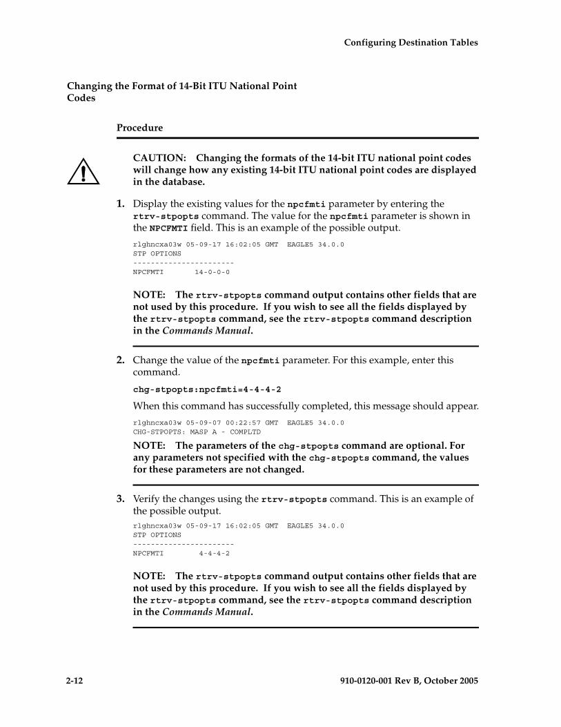
2-12 910-0120-001 Rev B, October 2005
Configuring Destination Tables
Changing the Format of 14-Bit ITU National Point Codes
Procedure
CAUTION: Changing the formats of the 14-bit ITU national point codes will change how any existing 14-bit ITU national point codes are displayed in the database.
1. Display the existing values for the npcfmti parameter by entering the rtrv-stpopts command. The value for the npcfmti parameter is shown in the NPCFMTI field. This is an example of the possible output.
rlghncxa03w 05-09-17 16:02:05 GMT EAGLE5 34.0.0STP OPTIONS-----------------------NPCFMTI 14-0-0-0
NOTE: The rtrv-stpopts command output contains other fields that are not used by this procedure. If you wish to see all the fields displayed by the rtrv-stpopts command, see the rtrv-stpopts command description in the Commands Manual.
2. Change the value of the npcfmti parameter. For this example, enter this command.
chg-stpopts:npcfmti=4-4-4-2
When this command has successfully completed, this message should appear.
rlghncxa03w 05-09-07 00:22:57 GMT EAGLE5 34.0.0CHG-STPOPTS: MASP A - COMPLTD
NOTE: The parameters of the chg-stpopts command are optional. For any parameters not specified with the chg-stpopts command, the values for these parameters are not changed.
3. Verify the changes using the rtrv-stpopts command. This is an example of the possible output.rlghncxa03w 05-09-17 16:02:05 GMT EAGLE5 34.0.0STP OPTIONS-----------------------NPCFMTI 4-4-4-2
NOTE: The rtrv-stpopts command output contains other fields that are not used by this procedure. If you wish to see all the fields displayed by the rtrv-stpopts command, see the rtrv-stpopts command description in the Commands Manual.
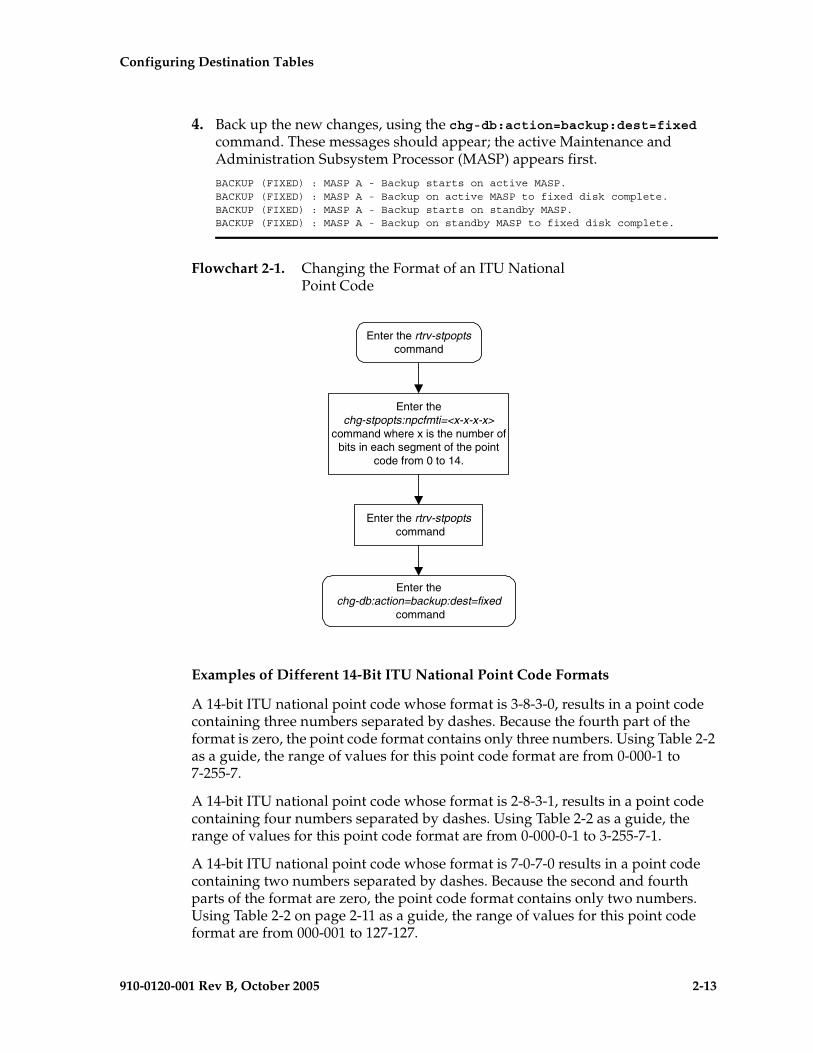
Configuring Destination Tables
910-0120-001 Rev B, October 2005 2-13
4. Back up the new changes, using the chg-db:action=backup:dest=fixed command. These messages should appear; the active Maintenance and Administration Subsystem Processor (MASP) appears first.
BACKUP (FIXED) : MASP A - Backup starts on active MASP.BACKUP (FIXED) : MASP A - Backup on active MASP to fixed disk complete.BACKUP (FIXED) : MASP A - Backup starts on standby MASP.BACKUP (FIXED) : MASP A - Backup on standby MASP to fixed disk complete.
Flowchart 2-1. Changing the Format of an ITU National Point Code
Examples of Different 14-Bit ITU National Point Code Formats
A 14-bit ITU national point code whose format is 3-8-3-0, results in a point code containing three numbers separated by dashes. Because the fourth part of the format is zero, the point code format contains only three numbers. Using Table 2-2 as a guide, the range of values for this point code format are from 0-000-1 to 7-255-7.
A 14-bit ITU national point code whose format is 2-8-3-1, results in a point code containing four numbers separated by dashes. Using Table 2-2 as a guide, the range of values for this point code format are from 0-000-0-1 to 3-255-7-1.
A 14-bit ITU national point code whose format is 7-0-7-0 results in a point code containing two numbers separated by dashes. Because the second and fourth parts of the format are zero, the point code format contains only two numbers. Using Table 2-2 on page 2-11 as a guide, the range of values for this point code format are from 000-001 to 127-127.
Enter the rtrv-stpoptscommand
Enter thechg-stpopts:npcfmti=<x-x-x-x>
command where x is the number ofbits in each segment of the point
code from 0 to 14.
Enter the rtrv-stpopts command
Enter thechg-db:action=backup:dest=fixed
command

2-14 910-0120-001 Rev B, October 2005
Configuring Destination Tables
A 14-bit ITU national point code whose format is 14-0-0-0 results in a point code containing a single number, containing up to five digits. Using Table 2-2 as a guide, the range of values for this point code format are from 1 to 16383.
Exception
The format defined by the npcfmti parameter of the chg-stpopts command applies to all database entities that use 14-bit ITU national point codes, except gateway screening. Gateway screening allows the 14-bit ITU national point code to be displayed and entered in the database only as a single number. If the EAGLE 5 SAS is using a format for the 14-bit ITU national point code other than a single number, the point code will have to be converted from its current format to a single number in order to be used by gateway screening.
Converting Single Number 14-Bit ITU National Point Codes
To convert a single number ITU national point code to a multiple part ITU national point code, perform these steps. For this example, the 14-bit ITU national point codes 14781 and 695 are converted to point codes using the 3-8-3-0 format.
1. The point code is converted to a binary number. This can be done with most scientific calculators.
a. The number 14781 converts to the binary number 11100110111101.
b. The number 695 converts to the binary number 1010110111.
NOTE: Make sure the binary number contains 14 digits. If it does not, add leading zeros to the binary number to bring the total number of digits in the number to 14.
In this example, the binary equivalent for the decimal number 695 (1010110111) contains 10 digits, so four zeros must be added to the beginning of the binary number. The resulting binary number is now 00001010110111.
2. Divide the binary number into the number of parts required by the format of the 14-bit ITU national point code. For this example, the format is 3-8-3-0. Since the last part of the point code format is 0, the point code format contains only three parts. Divide the point code into three parts: the first part of the point code contains the first three digits of the 14-digit binary number, the second part of the point code contains the next eight digits of the 14-digit binary number, and the third part of the point code contains the last three digits of the 14-digit binary number.
For this example, the binary numbers would be divided like this:
a. 11100110111101 = 111 00110111 101
b. 00001010110111 = 000 01010110 111

Configuring Destination Tables
910-0120-001 Rev B, October 2005 2-15
3. Convert each part of the point code into a decimal number, using the same scientific calculator used in step 1, and separate each part of the point code with dashes. The results are as follows.
a. 111 00110111 101 = 7-55-5
b. 000 01010110 111 = 0-86-7
When the 14-bit ITU national point codes are converted from single numbers to multiple-part point codes, the resulting value of the multiple-part point code depends on the point code format specified by the npcfmti parameter of the chg-stpopts command. When converting the single-number point code 14781 to the point code format 3-8-3-0, the resulting point code value is 7-55-5. If point code 14781 is converted to the point code format 4-4-4-2, the resulting point code value is 14-6-15-1.
Converting Multiple-Part 14-Bit ITU National Point Codes
To convert multiple-part 14-bit ITU national point codes to a single number, perform these steps. For this example, the 14-bit ITU national point codes 7-55-5 and 0-86-7, using the 3-8-3-0 point code format, are converted into a single number.
1. Convert each part of the point code into a binary number using a scientific calculator. The results are as follows.
a. 7-55-5 = 111 00110111 101
b. 0-86-7 = 000 01010110 111
2. Combine each part of the point code into a single binary number as follows.
a. 111 00110111 101 = 11100110111101
b. 000 01010110 111 = 00001010110111
NOTE: If the binary number has any zeros at the beginning of the number, remove these zeros, as they are not necessary.
In this example, the binary equivalent for the point code 0-86-7 (00001010110111) contains four zeros at the beginning of the binary number. When the leading zeros are removed from the binary number, the resulting binary number is now 1010110111.
3. Convert the binary number to a decimal number using the same scientific calculator used in step 1.
a. The binary number 11100110111101 converts to the decimal number 14781.
b. The binary number 1010110111 converts to the decimal number 695.

2-16 910-0120-001 Rev B, October 2005
Configuring Destination Tables
ITU National Duplicate Point Codes
NOTE: This feature applies only to 14-bit ITU national spare and non-spare point codes.
This feature allows an EAGLE 5 SAS mated pair to route traffic for two or more countries that may have overlapping point code values. For example, in the network shown in Figure 2-2, both Country 1 and Country 2 have SSPs with a PC value of 2047.
Figure 2-2. Network Example #1
Group Codes
Users must divide their ITU-National destinations into groups. These groups will likely be based on Country. However, one group could have multiple countries within it, or a single country could be divided into multiple groups. The requirements for these groups are:
• No duplicate point codes are allowed within a group.
• ITU-National traffic from a group must be destined for a PC within the same group.
• The user must assign a unique two-letter group code to each group.
Configuring Destination Tables
910-0120-001 Rev B, October 2005 2-17
For example, in the network shown in Figure 2-2 on page 2-16, Country 1 can only have 1 point code with a value of 2047. Traffic coming from SSP 2047 in Country 1 can only be destined to other nodes within Country 1. In this example, the user assigns a group code of 1 to Country 1, and a group code of 2 to Country 2.
When the user enters an ITU-National point code, they must also enter the group code, using the format “point code - group code”. This group code must be used for any command that uses an ITU-N point code.
For example, to provision the EAGLE 5 SAS for the network shown in Figure 2-2 on page 2-16, the user would enter these commands:
ent-dstn:dpcn=2047-aa
ent-dstn:dpcn=2048-aa
ent-dstn:dpcn=2047-ab
ent-dstn:dpcn=2049-ab
ent-ls:lsn=LS1:apcn=2047-aa
ent-ls:lsn=LS2:apcn=2047-ab
ent-ls:lsn=LS3:apcn=2048-aa
ent-ls:lsn=LS4:apcn=2049-ab
Group Code aa
The following special rules apply to group code aa:
• ITU-N MSUs received on an ITU-I linkset are assigned group code of aa.
• ITU-N destinations entered before this feature is turned on are assigned group code of aa when the ITUDUPPC feature bit is turned on.
Normal Operation
When an ITU-N message arrives at the EAGLE 5 SAS, the EAGLE 5 SAS creates an internal point code based on the 14 bit PC in the message, and the group code assigned to the incoming linkset.
For example, when a message arrives on LS3 with DPC of 2047, the EAGLE 5 SAS maps that to an internal point code of 2047-aa, because LS3 has a group code of aa. The EAGLE 5 SAS then routes the message to LS1, which is the route for 2047-aa.
When a message arrives on LS4 with DPC of 2047, the EAGLE 5 SAS maps that to an internal point code of 2047-ab, because LS4 uses group code ab. The EAGLE 5 SAS then routes the message to LS2, which is the route for 2047-ab.

2-18 910-0120-001 Rev B, October 2005
Configuring Destination Tables
C Linksets
For each group defined, a separate C-linkset must be defined. This C-linkset is used as the alternate route for point codes in the group.
For example, in Figure 2-3, LSC1 is used for point codes in Group fr. Its adjacent point code is 6201-fr, and is used as the alternate route for 6217-fr, 6218-fr, and 6223-fr.
LSC2 is used for point codes is Group ge. Its adjacent point code is group 4169-ge, and is used as the alternate route for 6200-ge, 6209-ge, and 6217-ge.
Figure 2-3. Network Example #2
Configuring Destination Tables
910-0120-001 Rev B, October 2005 2-19
For example, to provision the EAGLE 5 SAS for the network shown in Figure 2-3 on page 2-18, the user would enter these commands:
ent-dstn:dpcn=6201-fr (Mate's true PC)
ent-dstn:dpcn=4169-ge (Mate's secondary PC)
ent-dstn:dpcn=6217-fr (Group fr destinations)
ent-dstn:dpcn=6218-fr
ent-dstn:dpcn=6223-fr
ent-dstn:dpcn=6200-ge (Group ge destinations)
ent-dstn:dpcn=6217-ge
ent-dstn:dpcn=6209-ge
ent-ls:lsn=LSC1:apcn=6201-fr:lst=C (C linkset used by Group fr)
ent-ls:lsn=LSC2:apcn=4169-ge:lst=C (C linkset used by Group ge)
ent-ls:lsn=LSB1:apcn=6217-fr:lst=B
ent-ls:lsn=LSB2:apcn=6200-ge:lst=B
ent-rte:dpcn=6217-fr:lsn=LSB1:rc=10 (primary route for a Group fr destination)
ent-rte:dpcn=6217-fr:lsn=LSC1:rc=20 (alternate route for a Group fr destination)
ent-rte:dpcn=6217-ge:lsn=LSB2:rc=10 (primary route for a Group ge destination)
ent-rte:dpcn=6217-ge:lsn=LSC2:rc=20 (alternate route for a Group ge destination)
Receiving an ITU-National MSU on an ITU-International Linkset
It is possible for the EAGLE 5 SAS to receive ITU-National MSUs on an ITU-International linkset. A linkset is considered an ITU-International linkset if it's adjacent point code is an ITU-International PC. An MSU is ITU-National if it is received on an ITU linkset (National or International), and the NIC field in the SIO is set to 2 (National).
ITU-International linksets do not have a group code. ITU-National MSUs received on ITU-International linksets will be assigned a group code of aa.

2-20 910-0120-001 Rev B, October 2005
Configuring Destination Tables
Existing ITU National Destinations
Any ITU-National destinations that were entered before Release 26.05 or before the ITU National Duplicate Point Codes feature was turned on will be assigned the group code of aa.
Interaction with Other Features
Gateway Screening
For example, in the network in Figure 2-3 on page 2-18, if the user wanted to screen out MSU coming from 6217 in Group ge, but allow MSUs coming from 6217 in Group fr, he or she could assign different screensets to LSB1 and LSB2. The screenset assigned to LSB1 would allow MSUs from OPC 6217. The screenset assigned to LSB2 would block MSUs from OPC 6217.
Multiple Point Codes
The Multiple Point Codes feature (see “Multiple Point Code Support” on page 2-55) must be on in order to turn on the ITU National Duplicate Point Codes feature. For every group that is used, the user must provision either a True PC or Secondary Point Code, using the chg-sid command.
For example, in the network in Figure 2-3 on page 2-18, two groups are used having group codes of fr and ge. An ITU-National True Point Code is entered for group fr, and an ITU-National Secondary Point code is entered for group ge.
Conversion between ITU-N and ITU-I or ANSI
Each ITU-N destination and group code can have its own ITU-I or ANSI alias PC. Each ITU-I or ANSI node can be assigned one ITU-N destination. For conversion from ITU-I or ANSI to ITU-N to succeed, the ITU-N alias of the sending node must have the same group code as the destination's group code. So each ITU-I or ANSI node can only send and receive messages from one ITU-N group.

Configuring Destination Tables
910-0120-001 Rev B, October 2005 2-21
Figure 2-4. Network for Conversion
In Figure 2-4, SSP-N1 (2045-bd) is assigned ITU-I alias 1-6-1, and SSP-N2 (2045-xy) is assigned ITU-I alias 1-7-1. SSP-I1 is assigned ITU-N alias 2130-bd and SSP-I2 is assigned ITU-N alias 2131-xy. In this example, SSP-I1 can exchange traffic with nodes in group bd, but not nodes in group xy. SSP-I2 can exchange traffic with nodes in group xy, but not nodes in group bd.
SSP-I1 (1-5-1) can send to SSP-N1 by using the ITU-I alias 1-6-1, But if SSP-I1 tries to send to 2045-xy by using the ITU-I alias 1-7-1, conversion will fail, and the EAGLE 5 SAS will generate UIM 1091 (Indicating OPC conversion failed).
SSP-N1 can send traffic to SSP-I1, but SSP-N2 cannot send traffic to SSP-I1. SSP-N1 sends an ITU-N MSU with DPC set to 2130. The EAGLE 5 SAS assigns a group code of bd to the MSU based on the incoming linkset. The EAGLE 5 SAS then looks up 2130-bd, determines that this is an alias for ITU-I 1-5-1, and routes the MSU to SSP-I1.
If SSP-N2 sends an ITU-N MSU with DPC set to 2130, the EAGLE 5 SAS assigns a group code of xy to the MSU based on the incoming linkset. The EAGLE 5 SAS then looks up 2130-xy, does not find a match, and discards the MSU.

2-22 910-0120-001 Rev B, October 2005
Configuring Destination Tables
To provision the SSP-N1, SSP-N2, SSP-I1, and SSP-I2 in the network shown in Figure 2-4 on page 2-21, the following commands are used:
ent-dstn:dpcn=2045-bd:aliasi=1-6-1
ent-dstn:dpcn=2045-xy:aliasi=1-7-1
ent-dstn:dpci=1-5-1:aliasn=2130-bd
ent-dstn:dpci=1-5-2:aliasn=2131-xy
ent-rte:dpcn=2045-bd:lsn=LSB1:rc=10
ent-rte:dpcn=2045-xy:lsn=LSB2:rc=10
ent-rte:dpci=1-5-1:lsn=LSB3:rc=10
ent-rte:dpci=1-5-2:lsn=LSB3:rc=10
Limitations
The ITU National Duplicate Point Code feature has the following limitations:
• Duplicate Point Codes are only supported for ITU-National Destinations.
• ITU-National traffic from a group must be destined for a PC within the same group.
• No duplicate point codes are allowed within a group.
• For each group that is provisioned, a separate ITU-N C-linkset must be provisioned.
• It is not possible to change a destination's group code. If the user wants to move a destination from one group to another, the user must provision a new destination that uses the new group code and delete the old destination.
• If conversion between ITU-N and ITU-I or ANSI is used, only 1 ITU-N group can send traffic to a specific ANSI or ITU-I node.

Configuring Destination Tables
910-0120-001 Rev B, October 2005 2-23
Changing the DPC Quantity
This procedure is used to increase the number of DPCs that are allowed in the EAGLE 5 SAS beyond what is currently shown in the ent-dstn, dlt-dstn, chg-dstn, and rtrv-dstn outputs. The EAGLE 5 SAS can contain a maximum of one of these quantities: 2000 (system default), 5000, 6000, 7000, or 8000 DPCs.
To have more than 2000 DPCs in the EAGLE 5 SAS, the 5000 Routes feature must be turned on using the chg-feat command. Turning on the 5000 Routes features allows the EAGLE 5 SAS to contain a maximum of 5000 DPCs. To have more than 5000 DPCs in the EAGLE 5 SAS, either 6000, 7000, or 8000 routesets must be enabled using the enable-ctrl-feat command, in addition to having the 5000 Routes feature turned on. Enabling 6000, 7000, or 8000 routesets allows the EAGLE 5 SAS to contain a maximum of 6000, 7000, or 8000 DPCs. The rtrv-ctrl-feat command shows whether or not 6000, 7000, or 8000 routesets are enabled. The rtrv-feat command shows whether or not the 5000 Routes feature is turned on.
NOTE: Once the 5000 Routes feature is turned on with the chg-feat command, it cannot be turned off.
The 5000 Routes feature must be purchased before you turn this feature on with the chg-feat command. If you are not sure if you have purchased the 5000 Routes feature, contact your Tekelec Sales Representative or Account Representative.
Once the maximum DPC quantity is set, the actual number of DPCs allowed in the EAGLE 5 SAS is configured using the mtpdpcq parameter of the chg-stpopts command. The rtrv-stpopts command output, as well as the outputs of the ent-dstn, dlt-dstn, chg-dstn, and rtrv-dstn commands, shows the actual number of DPCs allowed in the EAGLE 5 SAS.
If the Cluster Routing and Management Diversity feature is turned on, (shown by the entry CRMD = on in the rtrv-feat output) the mtpxlq parameter is also shown in the rtrv-stpopts output. The mtpxlq parameter defines the maximum number of entries that the exception list (x-list) for the Cluster Routing and Management Diversity feature can contain. The value of the mtpxlq parameter of the chg-stpopts command can also be changed to more than 2000 destination point codes. For more information on exception lists, see “Exception Lists (X-lists)” on page 2-120.
The enable-ctrl-feat command enables 6000, 7000, or 8000 routesets by inputting the part number for the routeset quantity and the routeset quantity’s feature access key with these parameters:
:partnum – The Tekelec-issued part number for the routeset quantity:
• For 6000 routesets - 893006401
• For 7000 routesets - 893006402
• For 8000 routesets - 893006403.

2-24 910-0120-001 Rev B, October 2005
Configuring Destination Tables
:fak – The feature access key supplied by Tekelec. The feature access key contains 13 alphanumeric characters and is not case sensitive.
NOTE: The values for the feature access key (the fak parameter) are provided by Tekelec. If you do not have the feature access key for the routeset quantity you wish to enable, contact your Tekelec Sales Representative or Account Representative.
The enable-ctrl-feat command requires a valid serial number for the EAGLE 5 SAS to be configured in the database, and that this serial number is locked. This can be verified with the rtrv-serial-num command. The EAGLE 5 SAS is shipped with a serial number in the database, but the serial number is not locked. The serial number can be changed, if necessary, and locked once the EAGLE 5 SAS is on-site, by using the ent-serial-num command. The ent-serial-num command uses these parameters.
:serial – The serial number assigned to the EAGLE 5 SAS. The serial number is not case sensitive.
:lock – Specifies whether or not the serial number is locked. This parameter has only one value, yes, which locks the serial number. Once the serial number is locked, it cannot be changed.
NOTE: To enter and lock the EAGLE 5 SAS’s serial number, the ent-serial-num command must be entered twice, once to add the correct serial number to the database with the serial parameter, then again with the serial and the lock=yes parameters to lock the serial number. You should verify that the serial number in the database is correct before locking the serial number. The serial number can be found on a label affixed to the control shelf (shelf 1100).
To enable 7000 or 8000 routesets, the DPC table can contain no more than 8000 alias point codes. The number of alias point codes configured in the EAGLE 5 SAS is shown in the output of the ent-dstn, dlt-dstn, chg-dstn, and rtrv-dstn command outputs in one of two ways, depending on whether or not the Cluster Routing and Management Diversity feature is on or off.
If the Cluster Routing and Management Diversity feature is off:rlghncxa03w 05-09-17 16:02:05 GMT EAGLE5 34.0.0Destination table is (10 of 8000) 1% fullAlias table is (8 of 8000) 1% fullRTRV-DSTN: MASP A - COMPLTD
If the Cluster Routing and Management Diversity feature is on:rlghncxa03w 05-09-17 16:02:05 GMT EAGLE5 34.0.0DESTINATION ENTRIES ALLOCATED: 8000 FULL DPC(s): 9 NETWORK DPC(s): 0 CLUSTER DPC(s): 1 TOTAL DPC(s): 10 CAPACITY (% FULL): 1%ALIASES ALLOCATED: 8000 ALIASES USED: 8 CAPACITY (% FULL): 1%X-LIST ENTRIES ALLOCATED: 500RTRV-DSTN: MASP A - COMPLTD
Configuring Destination Tables
910-0120-001 Rev B, October 2005 2-25
To set the alias point code quantity below 8000, perform the “Changing a Destination Point Code” procedure on page 2-226. The alias point codes are removed using this procedure.
The routeset quantities (6000, 7000, or 8000) cannot be temporarily enabled (with a temporary feature access key) and cannot be disabled with the chg-ctrl-feat command and the status=off parameter. The routeset quantity cannot be decreased to a smaller quantity once a quantity is enabled. For example, if the current routeset quantity of the EAGLE 5 SAS is 7000 routesets, the quantity cannot be reduced to 6000 routesets.
Once any of these routeset quantities are enabled with the enable-ctrl-feat command, they are also activated. The chg-ctrl-feat command is not necessary to activate these routeset quantities.
Procedure
1. Display the DPC quantity currently allowed in the EAGLE 5 SAS by entering the rtrv-stpopts command. The DPC quantity is displayed in the MTPDPCQ field of the output. This is an example of the possible output.
rlghncxa03w 05-09-17 16:02:05 GMT EAGLE5 34.0.0STP OPTIONS-----------------------MTPDPCQ 1750
NOTE: The rtrv-stpopts command output contains other fields that are not used by this procedure. If you wish to see all the fields displayed by the rtrv-stpopts command, see the rtrv-stpopts command description in the Commands Manual.
The MTPDPCQ value cannot exceed one of these totals depending on the features that are enabled or turned on:
• 2000 – if the 5000 Routes feature is not on, and 6000, 7000, or 8000 routesets are not enabled.
• 5000 – if the 5000 Routes feature is on, and 6000, 7000, or 8000 routesets are not enabled.
• 6000 – if 6000 routesets are enabled.
• 7000 – if 7000 routesets are enabled.
• 8000 – if 8000 routesets are enabled.
If the Cluster Routing and Management Diversity feature is on, the MTPXLQ field will be shown in the rtrv-stpopts command output. The MTPXLQ field shows the maximum number of entries the exception list (x-list) can contain.
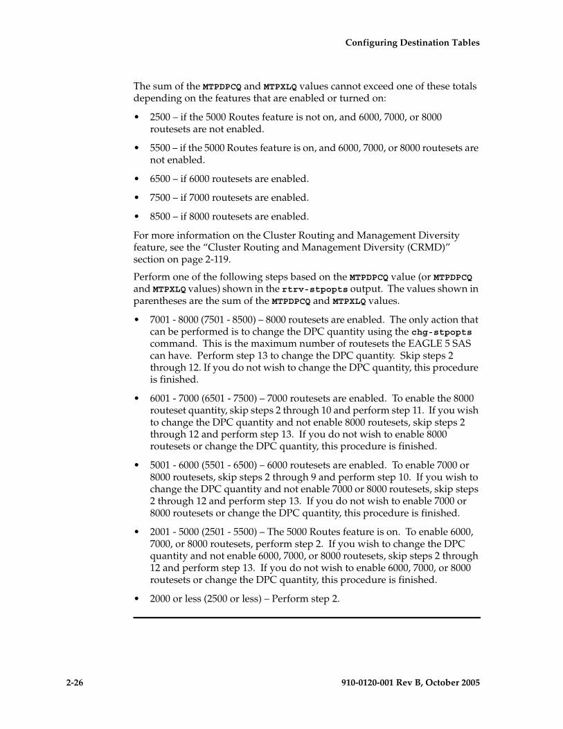
2-26 910-0120-001 Rev B, October 2005
Configuring Destination Tables
The sum of the MTPDPCQ and MTPXLQ values cannot exceed one of these totals depending on the features that are enabled or turned on:
• 2500 – if the 5000 Routes feature is not on, and 6000, 7000, or 8000 routesets are not enabled.
• 5500 – if the 5000 Routes feature is on, and 6000, 7000, or 8000 routesets are not enabled.
• 6500 – if 6000 routesets are enabled.
• 7500 – if 7000 routesets are enabled.
• 8500 – if 8000 routesets are enabled.
For more information on the Cluster Routing and Management Diversity feature, see the “Cluster Routing and Management Diversity (CRMD)” section on page 2-119.
Perform one of the following steps based on the MTPDPCQ value (or MTPDPCQ and MTPXLQ values) shown in the rtrv-stpopts output. The values shown in parentheses are the sum of the MTPDPCQ and MTPXLQ values.
• 7001 - 8000 (7501 - 8500) – 8000 routesets are enabled. The only action that can be performed is to change the DPC quantity using the chg-stpopts command. This is the maximum number of routesets the EAGLE 5 SAS can have. Perform step 13 to change the DPC quantity. Skip steps 2 through 12. If you do not wish to change the DPC quantity, this procedure is finished.
• 6001 - 7000 (6501 - 7500) – 7000 routesets are enabled. To enable the 8000 routeset quantity, skip steps 2 through 10 and perform step 11. If you wish to change the DPC quantity and not enable 8000 routesets, skip steps 2 through 12 and perform step 13. If you do not wish to enable 8000 routesets or change the DPC quantity, this procedure is finished.
• 5001 - 6000 (5501 - 6500) – 6000 routesets are enabled. To enable 7000 or 8000 routesets, skip steps 2 through 9 and perform step 10. If you wish to change the DPC quantity and not enable 7000 or 8000 routesets, skip steps 2 through 12 and perform step 13. If you do not wish to enable 7000 or 8000 routesets or change the DPC quantity, this procedure is finished.
• 2001 - 5000 (2501 - 5500) – The 5000 Routes feature is on. To enable 6000, 7000, or 8000 routesets, perform step 2. If you wish to change the DPC quantity and not enable 6000, 7000, or 8000 routesets, skip steps 2 through 12 and perform step 13. If you do not wish to enable 6000, 7000, or 8000 routesets or change the DPC quantity, this procedure is finished.
• 2000 or less (2500 or less) – Perform step 2.
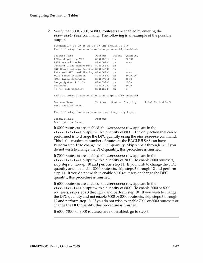
Configuring Destination Tables
910-0120-001 Rev B, October 2005 2-27
2. Verify that 6000, 7000, or 8000 routesets are enabled by entering the rtrv-ctrl-feat command. The following is an example of the possible output.
rlghncxa03w 05-09-28 21:15:37 GMT EAGLE5 34.0.0The following features have been permanently enabled:
Feature Name Partnum Status QuantityIPGWx Signaling TPS 893012814 on 20000ISUP Normalization 893000201 on ----Command Class Management 893005801 on ----LNP Short Message Service 893006601 on ----Intermed GTT Load Sharing 893006901 on ----XGTT Table Expansion 893006101 on 4000000XMAP Table Expansion 893007710 on 3000Large System # Links 893005901 on 1500Routesets 893006401 on 6000HC-MIM SLK Capacity 893012707 on 64
The following features have been temporarily enabled:
Feature Name Partnum Status Quantity Trial Period LeftZero entries found.
The following features have expired temporary keys:
Feature Name PartnumZero entries found.
If 8000 routesets are enabled, the Routesets row appears in the rtrv-ctrl-feat output with a quantity of 8000. The only action that can be performed is to change the DPC quantity using the chg-stpopts command. This is the maximum number of routesets the EAGLE 5 SAS can have. Perform step 13 to change the DPC quantity. Skip steps 3 through 12. If you do not wish to change the DPC quantity, this procedure is finished.
If 7000 routesets are enabled, the Routesets row appears in the rtrv-ctrl-feat output with a quantity of 7000. To enable 8000 routesets, skip steps 3 through 10 and perform step 11. If you wish to change the DPC quantity and not enable 8000 routesets, skip steps 3 through 12 and perform step 13. If you do not wish to enable 8000 routesets or change the DPC quantity, this procedure is finished.
If 6000 routesets are enabled, the Routesets row appears in the rtrv-ctrl-feat output with a quantity of 6000. To enable 7000 or 8000 routesets, skip steps 3 through 9 and perform step 10. If you wish to change the DPC quantity and not enable 7000 or 8000 routesets, skip steps 3 through 12 and perform step 13. If you do not wish to enable 7000 or 8000 routesets or change the DPC quantity, this procedure is finished.
If 6000, 7000, or 8000 routesets are not enabled, go to step 3.

2-28 910-0120-001 Rev B, October 2005
Configuring Destination Tables
3. Enter the rtrv-feat command and verify that the 5000 Routes feature is turned on. If the 5000 Routes feature is on, the DSTN5000 = on entry appears in the output.
NOTE: The rtrv-feat command output contains other fields that are not used by this procedure. If you wish to see all the fields displayed by the rtrv-feat command, see the rtrv-feat command description in the Commands Manual.
If the 5000 Routes feature is not on, and you do not wish to turn the 5000 Routes feature on, or enable 6000, 7000 or 8000 routesets, the only action that can be performed is to change the DPC quantity using the chg-stpopts command. However the DPC quantity can be no greater than 2000 DPCs (2500 DPCs if the rtrv-stpopts output in step 1 contains the MTPDPCQ and MTPXLQ parameters). Perform step 13 to change the DPC quantity. Skip steps 4 through 12. If you do not wish to change the DPC quantity, this procedure is finished.
If the 5000 Routes feature is not on, and you wish to turn the 5000 Routes feature on, or enable 6000, 7000 or 8000 routesets, go to step 4.
If the 5000 Routes feature is on, skip steps 4 and 5, and go to step 6.
4. Turn the 5000 Routes feature on by entering this command.
chg-feat:DSTN5000=on
NOTE: Once the 5000 Routes feature is turned on with the chg-feat command, it cannot be turned off.
The 5000 Routes feature must be purchased before you turn this feature on with the chg-feat command. If you are not sure if you have purchased the 5000 Routes feature, contact your Tekelec Sales Representative or Account Representative.
When the chg-feat has successfully completed, this message appears.
rlghncxa03w 05-09-28 11:43:04 GMT EAGLE5 34.0.0CHG-FEAT: MASP A - COMPLTD
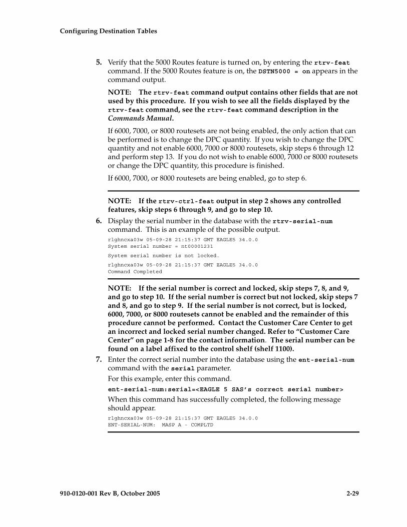
Configuring Destination Tables
910-0120-001 Rev B, October 2005 2-29
5. Verify that the 5000 Routes feature is turned on, by entering the rtrv-feat command. If the 5000 Routes feature is on, the DSTN5000 = on appears in the command output.
NOTE: The rtrv-feat command output contains other fields that are not used by this procedure. If you wish to see all the fields displayed by the rtrv-feat command, see the rtrv-feat command description in the Commands Manual.
If 6000, 7000, or 8000 routesets are not being enabled, the only action that can be performed is to change the DPC quantity. If you wish to change the DPC quantity and not enable 6000, 7000 or 8000 routesets, skip steps 6 through 12 and perform step 13. If you do not wish to enable 6000, 7000 or 8000 routesets or change the DPC quantity, this procedure is finished.
If 6000, 7000, or 8000 routesets are being enabled, go to step 6.
NOTE: If the rtrv-ctrl-feat output in step 2 shows any controlled features, skip steps 6 through 9, and go to step 10.
6. Display the serial number in the database with the rtrv-serial-num command. This is an example of the possible output.rlghncxa03w 05-09-28 21:15:37 GMT EAGLE5 34.0.0System serial number = nt00001231
System serial number is not locked.
rlghncxa03w 05-09-28 21:15:37 GMT EAGLE5 34.0.0Command Completed
NOTE: If the serial number is correct and locked, skip steps 7, 8, and 9, and go to step 10. If the serial number is correct but not locked, skip steps 7 and 8, and go to step 9. If the serial number is not correct, but is locked, 6000, 7000, or 8000 routesets cannot be enabled and the remainder of this procedure cannot be performed. Contact the Customer Care Center to get an incorrect and locked serial number changed. Refer to “Customer Care Center” on page 1-8 for the contact information. The serial number can be found on a label affixed to the control shelf (shelf 1100).
7. Enter the correct serial number into the database using the ent-serial-num command with the serial parameter. For this example, enter this command.ent-serial-num:serial=<EAGLE 5 SAS’s correct serial number>
When this command has successfully completed, the following message should appear.rlghncxa03w 05-09-28 21:15:37 GMT EAGLE5 34.0.0ENT-SERIAL-NUM: MASP A - COMPLTD

2-30 910-0120-001 Rev B, October 2005
Configuring Destination Tables
8. Verify that the serial number entered into step 7 was entered correctly using the rtrv-serial-num command. This is an example of the possible output.rlghncxa03w 05-09-28 21:15:37 GMT EAGLE5 34.0.0System serial number = nt00001231
System serial number is not locked.
rlghncxa03w 05-09-28 21:15:37 GMT EAGLE5 34.0.0Command Completed
If the serial number was not entered correctly, repeat steps 7 and 8 and re-enter the correct serial number.
9. Lock the serial number in the database by entering the ent-serial-num command with the serial number shown in step 6, if the serial number shown in step 6 is correct, or with the serial number shown in step 8, if the serial number was changed in step 7, and with the lock=yes parameter.
For this example, enter this command.ent-serial-num:serial=<EAGLE 5 SAS’s serial number>:lock=yes
When this command has successfully completed, the following message should appear.rlghncxa03w 05-09-28 21:15:37 GMT EAGLE5 34.0.0ENT-SERIAL-NUM: MASP A - COMPLTD
NOTE: If 7000 or 8000 routesets are not being enabled, skip step 10 and go to step 11.
NOTE: If 7000 routesets are currently enabled, and 8000 routesets are being enabled, skip step 10 and go to step 11.
10. Verify the number of alias point codes configured in the EAGLE 5 SAS by entering the rtrv-dstn command with the msar=only parameter.
To enable 7000 or 8000 routesets, the EAGLE 5 SAS can have no more than 8000 alias point codes.
The msar=only parameter displays only the maximum numbers of different types of point codes the EAGLE 5 SAS can have and the actual numbers of the different types of point codes that are configured in the EAGLE 5 SAS.
rtrv-dstn:msar=only
One of two types of outputs are displayed, depending on whether or not the Cluster Routing and Management Diversity feature is on or off.
If the Cluster Routing and Management Diversity feature is off:
rlghncxa03w 05-09-17 16:02:05 GMT EAGLE5 34.0.0Destination table is (10 of 8000) 1% fullAlias table is (8 of 8000) 1% fullRTRV-DSTN: MASP A - COMPLTD
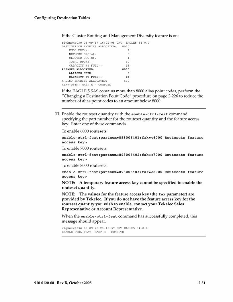
Configuring Destination Tables
910-0120-001 Rev B, October 2005 2-31
If the Cluster Routing and Management Diversity feature is on:
rlghncxa03w 05-09-17 16:02:05 GMT EAGLE5 34.0.0DESTINATION ENTRIES ALLOCATED: 8000 FULL DPC(s): 9 NETWORK DPC(s): 0 CLUSTER DPC(s): 1 TOTAL DPC(s): 10 CAPACITY (% FULL): 1%ALIASES ALLOCATED: 8000 ALIASES USED: 8 CAPACITY (% FULL): 1%X-LIST ENTRIES ALLOCATED: 500RTRV-DSTN: MASP A - COMPLTD
If the EAGLE 5 SAS contains more than 8000 alias point codes, perform the “Changing a Destination Point Code” procedure on page 2-226 to reduce the number of alias point codes to an amount below 8000.
11. Enable the routeset quantity with the enable-ctrl-feat command specifying the part number for the routeset quantity and the feature access key. Enter one of these commands.
To enable 6000 routesets:enable-ctrl-feat:partnum=893006401:fak=<6000 Routesets feature access key>
To enable 7000 routesets:enable-ctrl-feat:partnum=893006402:fak=<7000 Routesets feature access key>
To enable 8000 routesets:enable-ctrl-feat:partnum=893006403:fak=<8000 Routesets feature access key>
NOTE: A temporary feature access key cannot be specified to enable the routeset quantity.
NOTE: The values for the feature access key (the fak parameter) are provided by Tekelec. If you do not have the feature access key for the routeset quantity you wish to enable, contact your Tekelec Sales Representative or Account Representative.
When the enable-ctrl-feat command has successfully completed, this message should appear.
rlghncxa03w 05-09-28 21:15:37 GMT EAGLE5 34.0.0ENABLE-CTRL-FEAT: MASP B - COMPLTD
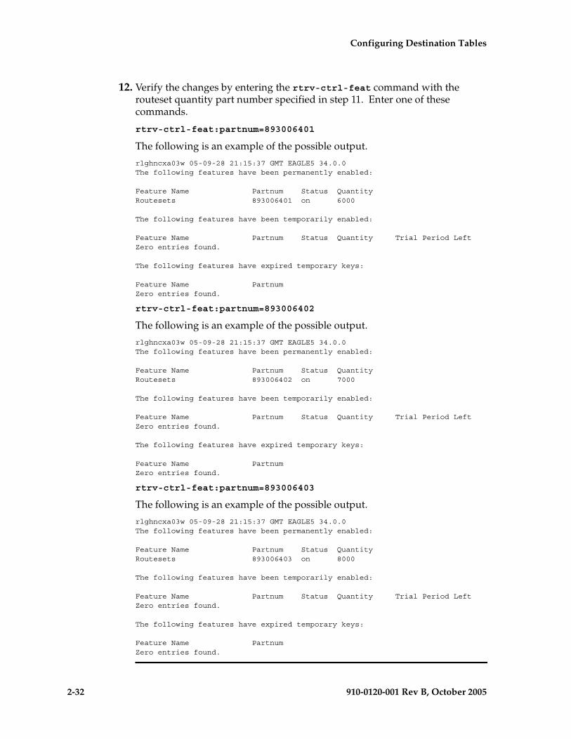
2-32 910-0120-001 Rev B, October 2005
Configuring Destination Tables
12. Verify the changes by entering the rtrv-ctrl-feat command with the routeset quantity part number specified in step 11. Enter one of these commands.
rtrv-ctrl-feat:partnum=893006401
The following is an example of the possible output.
rlghncxa03w 05-09-28 21:15:37 GMT EAGLE5 34.0.0The following features have been permanently enabled:
Feature Name Partnum Status QuantityRoutesets 893006401 on 6000
The following features have been temporarily enabled:
Feature Name Partnum Status Quantity Trial Period LeftZero entries found.
The following features have expired temporary keys:
Feature Name PartnumZero entries found.
rtrv-ctrl-feat:partnum=893006402
The following is an example of the possible output.
rlghncxa03w 05-09-28 21:15:37 GMT EAGLE5 34.0.0The following features have been permanently enabled:
Feature Name Partnum Status QuantityRoutesets 893006402 on 7000
The following features have been temporarily enabled:
Feature Name Partnum Status Quantity Trial Period LeftZero entries found.
The following features have expired temporary keys:
Feature Name PartnumZero entries found.
rtrv-ctrl-feat:partnum=893006403
The following is an example of the possible output.
rlghncxa03w 05-09-28 21:15:37 GMT EAGLE5 34.0.0The following features have been permanently enabled:
Feature Name Partnum Status QuantityRoutesets 893006403 on 8000
The following features have been temporarily enabled:
Feature Name Partnum Status Quantity Trial Period LeftZero entries found.
The following features have expired temporary keys:
Feature Name PartnumZero entries found.

Configuring Destination Tables
910-0120-001 Rev B, October 2005 2-33
NOTE: If the DPC quantity or exception list quantity are not being changed, skip steps 13 and 14, and go to step 15.
13. Change the maximum number of destination point codes that the EAGLE 5 SAS can contain by entering the chg-stpopts command with the mtpdpcq parameter. The values that can be specified with the mtpdpcq parameter is shown in the following list.
• 500 to 2000 – if the 5000 Routes feature is not on, and 6000, 7000, or 8000 routesets are not enabled.
• 500 to 5000 – if the 5000 Routes feature is on, and 6000, 7000, or 8000 routesets are not enabled.
• 500 to 6000 – if 6000 routesets are enabled.
• 500 to 7000 – if 7000 routesets are enabled.
• 500 to 8000 – if 8000 routesets are enabled.
For this example, enter this command.
chg-stpopts:mtpdpcq=7350
When this command has successfully completed, this message should appear.
rlghncxa03w 05-09-07 00:22:57 GMT EAGLE5 34.0.0CHG-STPOPTS: MASP A - COMPLTD
If the MTPXLQ field (the exception list quantity) is shown in the rtrv-stpopts output in step 1, and you wish to change only the MTPXLQ value, enter the chg-stpopts command with the mtpxlq parameter. For example, if you wish to change the exception list quantity to 1000 point codes, enter this command.
chg-stpopts:mtpxlq=1000
NOTE: The values that can be specified for the mtpxlq parameter are the same as the values for the mtpdpcq parameter and are shown in the list at the beginning of this step. However, if 7000 or 8000 routesets are enabled, the range of values for the mtpxlq parameter is 500 to 6000.
Both the exception list quantity and the maximum of destination point codes can be changed, by entering the chg-stpopts command with both the mptdpcq and mptxlq parameters. For example, if you wish to change the exception list quantity to 1000 point codes and the maximum number of point codes to 6200, enter this command.
chg-stpopts:mtpxlq=1000:mtpdpcq=6750
When specifying the mtpxlq parameter with the chg-stpopts command, the resulting sum of the MTPDPCQ and MTPXLQ values cannot be greater than the values shown in the following list:
• 2500 – if the 5000 Routes feature is not on, and 6000, 7000, or 8000 routesets are not enabled.
• 5500 – if the 5000 Routes feature is on, and 6000, 7000, or 8000 routesets are not enabled.

2-34 910-0120-001 Rev B, October 2005
Configuring Destination Tables
• 6500 – if 6000 routesets are enabled.
• 7500 – if 7000 routesets are enabled.
• 8500 – if 8000 routesets are is enabled.
14. Verify the changes using the rtrv-stpopts command. This is an example of the possible output.
rlghncxa03w 05-09-17 16:02:05 GMT EAGLE5 34.0.0STP OPTIONS-----------------------MTPDPCQ 7350
NOTE: The rtrv-stpopts command output contains other fields that are not used by this procedure. If you wish to see all the fields displayed by the rtrv-stpopts command, see the rtrv-stpopts command description in the Commands Manual.
If the mtpxlq parameter was specified in step 13, that value will be shown in the MTPXLQ field of the rtrv-stpopts command output.
15. Back up the new changes, using the chg-db:action=backup:dest=fixed command. These messages should appear; the active Maintenance and Administration Subsystem Processor (MASP) appears first.
BACKUP (FIXED): MASP A - Backup starts on active MASP.BACKUP (FIXED): MASP A - Backup on active MASP to fixed disk complete.BACKUP (FIXED): MASP A - Backup starts on standby MASP.BACKUP (FIXED): MASP A - Backup on standby MASP to fixed disk complete.
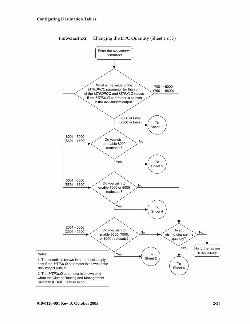
Configuring Destination Tables
910-0120-001 Rev B, October 2005 2-35
Flowchart 2-2. Changing the DPC Quantity (Sheet 1 of 7)
Enter the rtrv-stpoptscommand
What is the value of theMTPDPCQ parameter (or the sum
of the MTPDPCQ and MTPXLQ values if the MTPXLQ parameter is shown)
in the rtrv-stpopts output?
7001 - 8000(7501 - 8500)
2000 or Less(2500 or Less)
No further actionis necessary
Do youwish to change the
quantity?
6001 - 7000(6501 - 7500)
5001 - 6000(5501 - 6500)
2001 - 5000(2501 - 5500)
ToSheet 2
Do you wishto enable 8000
routesets?
Do you wish toenable 7000 or 8000
routesets?
Do you wish toenable 6000, 7000,or 8000 routesets?
ToSheet 5
ToSheet 4
ToSheet 6
Yes
No
Yes
No
Yes
No
Yes
No
Notes:
1. The quantities shown in paranthesis applyonly if the MTPXLQ parameter is shown in thertrv-stpopts output.
2. The MTPXLQ parameter is shown onlywhen the Cluster Routing and ManagementDiversity (CRMD) feature is on.
ToSheet 2

2-36 910-0120-001 Rev B, October 2005
Configuring Destination Tables
Flowchart 2-2. Changing the DPC Quantity (Sheet 2 of 7)
Enter the rtrv-featcommand
Is the5000 routesfeature on?
Enter thechg-feat:DSTN5000=oncommand (See Note)
Enter the rtrv-featcommand
No
Enter the rtrv-ctrl-featcommand
Are 6000, 7000,or 8000 routesets
enabled?
Yes
No
ToSheet 3
FromSheet 1
No further actionis necessary
Do youwish to change the
DPC quantity?
ToSheet 6
Yes
No
YesYes
Will therouteset quantityremain at 5000?
No
Yes
Note: Before turning this feature on,make sure you have purchased the5000 Routes feature. If you are not
sure if you have purchased the 5000Routes feature, contact you Tekelec
Sales Representative or AccountRepresentative.
Do you wish toincrease the routeset
quantity?
ToSheet 4
No
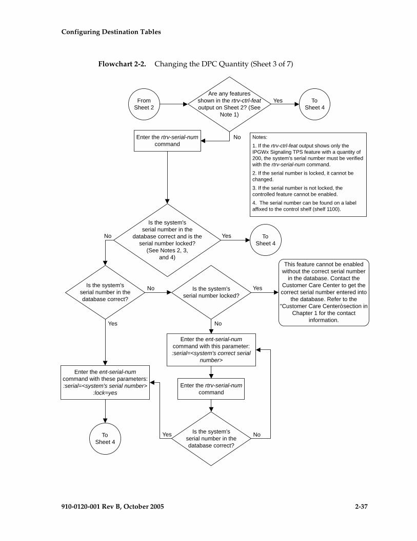
Configuring Destination Tables
910-0120-001 Rev B, October 2005 2-37
Flowchart 2-2. Changing the DPC Quantity (Sheet 3 of 7)
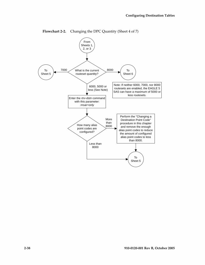
2-38 910-0120-001 Rev B, October 2005
Configuring Destination Tables
Flowchart 2-2. Changing the DPC Quantity (Sheet 4 of 7)

Configuring Destination Tables
910-0120-001 Rev B, October 2005 2-39
Flowchart 2-2. Changing the DPC Quantity (Sheet 5 of 7)
Enter the enable-ctrl-feat command withthese parameters:
:partnum=893006402:fak=<7000 routeset quantity featureaccess key> (See Notes 1, 2, and 3)
Notes:
1. Once this feature is enabled, it cannot be disabled or turned off.
2. This feature cannot be enabled with a temporary feature access key.
3. If you do not have the feature access key for the feature you wish toenable, contact your Tekelec Sales Representative or AccountRepresentative.
Enter the rtrv-ctrl-feat command withthis parameter:
:partnum=<part number specified inthe enable-ctrl-feat command>
6000 Which routesetquantity do you wish to
enable?
FromSheets 1, 3,
or 4
7000
8000
Enter the enable-ctrl-feat command withthese parameters:
:partnum=893006401:fak=<6000 routeset quantity featureaccess key> (See Notes 1, 2, and 3)
Enter the enable-ctrl-feat command withthese parameters:
:partnum=893006403:fak=<8000 routeset quantity featureaccess key> (See Notes 1, 2, and 3)
ToSheet 6

2-40 910-0120-001 Rev B, October 2005
Configuring Destination Tables
Flowchart 2-2. Changing the DPC Quantity (Sheet 6 of 7)
Enter thechg-db:action=backup:dest=fixed
command
Enter the rtrv-stpoptscommand
Was the MTPXLQparameter shown in thertrv-stpopts output on
Sheet 1?
ToSheet 7
Yes
No
FromSheets 1, 2,
4, or 5
Note: The value for the mtpdpcq parameter is shown in the following list and isdependent on the routeset quantity that is enabled with the enable-ctrl-feat command,or turned on with the chg-feat command:
! 5000 routes not turned on, 6000, 7000, or 8000 routesets not enabled - 500 to 2000
! 5000 routes turned on, 6000, 7000, or 8000 routesets not enabled - 500 to 5000
! 6000 routesets enabled - 500 to 6000
! 7000 routesets enabled - 500 to 7000
! 8000 routesets enabled - 500 to 8000
Enter thechg-stpopts:mtpdpcq=<See Note>
command

Configuring Destination Tables
910-0120-001 Rev B, October 2005 2-41
Flowchart 2-2. Changing the DPC Quantity (Sheet 7 of 7)
Enter thechg-db:action=backup:dest=fixed
command
Enter the chg-stpopts command withthese parameters:
:mtpdpcq=<See Note 1>:mtpxlq=<See Note 1>
Is theexception list quantity
or the DPC quantity to bechanged ?
(See Note 2)
Exception ListQuantity
DPCQuantity
Both DPC andException List
Quantity
Enter the rtrv-stpoptscommand
FromSheet 6
Notes:1. The sum of the values for the mtpdpcq and mtpxlq parameters cannot exceed these values, dependingwhich routeset quantity has been enabled with the enable-ctrl-feat command, or turned on with the chg-featcommand:
! 5000 routes not turned on, 6000, 7000, or 8000 routesets not enabled - 2500. The range of values for themtpdpcq and mtpxlq parameters is 500 to 2000.
! 5000 routes turned on, 6000, 7000, or 8000 routesets not enabled - 5500. The range of values for themtpdpcq and mtpxlq parameters is 500 to 5000.
! 6000 routesets enabled - 6500. The range of values for the mtpdpcq and mtpxlq parameters is 500 to 6000.! 7000 routesets enabled - 7500. The range of values for the mtpdpcq parameter is 500 to 7000. The range of
values for the mtpxlq parameter is 500 to 6000.! 8000 routesets enabled - 8500. The range of values for the mtpdpcq parameter is 500 to 8000. The range of
values for the mtpxlq parameter is 500 to 6000.2. If the DPC quantity or the exception list quantity is being changed, both the mtpdpcq and mtpxlqparameters do not have to be specified unless the resulting sum of the mtpdpcq and mtpxlq parameterswould exceed the totals shown in Note 1.For example, the current mtpdpcq value is 4000 and the current mtpxlq value is 1500, resulting in a sum of5500, and only the 5000 Routes feature is on. To increase either value, both parameters must be specifiedand the sum of the new values cannot exceed 5500. If either value is being decreased, the other parametercan be specified as long as the sum of the values does not exceed 5500.If in this example, the current mtpdpcq value is 3000 and the current mtpxlq value is 1500, resulting in a sumof 4500, either parameter value can be changed without specifying the other parameter as long as the sum ofthe values does not exceed 5500.
Enter the chg-stpoptscommand with this
parameter::mtpxlq=<See Note 1>
Enter the chg-stpoptscommand with this
parameter::mtpdpcq=<See Note 1>

2-42 910-0120-001 Rev B, October 2005
Configuring Destination Tables
Activating the ITU National and International Spare Point Code Support Feature
This feature allows ITU international (ITU-I) and 14-bit ITU national (ITU-N) spare point codes to be provisioned in the database. To provision these point codes, the ITU National and International Spare Point Code Support feature must be enabled with the enable-ctrl-feat command. Turning this feature on with the chg-ctrl-feat command allows the EAGLE 5 SAS to route messages using ITU-I and 14-bit ITU-N spare point codes.
The enable-ctrl-feat command enables the ITU National and International Spare Point Code Support feature by inputting the feature’s access key and the feature’s part number with these parameters:
:fak – The feature access key generated by the feature access key generator. The feature access key contains 13 alphanumeric characters and is not case sensitive.
:partnum – The Tekelec-issued part number of the ITU National and International Spare Point Code Support feature, 893013601.
Once this feature is enabled, it is permanently enabled. This feature cannot be enabled with a temporary feature access key.
If the EAGLE 5 SAS contains TALI sockets assigned to cards running the IPGWI application, these sockets must be removed before this feature can be enabled.
The enable-ctrl-feat command requires that the database contain a valid serial number for the EAGLE 5 SAS, and that this serial number is locked. This can be verified with the rtrv-serial-num command. The EAGLE 5 SAS is shipped with a serial number in the database, but the serial number is not locked. The serial number can be changed, if necessary, and locked once the EAGLE 5 SAS is on-site, with the ent-serial-num command. The ent-serial-num command uses these parameters.
:serial – The serial number assigned to the EAGLE 5 SAS. The serial number is not case sensitive.
:lock – Specifies whether or not the serial number is locked. This parameter has only one value, yes, which locks the serial number. Once the serial number is locked, it cannot be changed.
NOTE: To enter and lock the EAGLE 5 SAS’s serial number, the ent-serial-num command must be entered twice, once to add the correct serial number to the database with the serial parameter, then again with the serial and the lock=yes parameters to lock the serial number. You should verify that the serial number in the database is correct before locking the serial number. The serial number can be found on a label affixed to the control shelf (shelf 1100).

Configuring Destination Tables
910-0120-001 Rev B, October 2005 2-43
The chg-ctrl-feat command uses these parameters:
:partnum – The Tekelec-issued part number of the ITU National and International Spare Point Code Support feature, 893013601.
:status=on – used to turn the ITU National and International Spare Point Code Support on.
The status of the controlled features in the EAGLE 5 SAS is shown with the rtrv-ctrl-feat command.
Once the ITU National and International Spare Point Code Support is enabled, ITU-I or 14-bit ITU-N spare point codes can be added to the EAGLE 5 SAS. To do this, perform these procedures to provision these database entities:
1. To add spare point codes to the self identification of the EAGLE 5 SAS - “Adding a Point Code to the Self-Identification of the EAGLE 5 SAS” procedure on page 2-81
2. To change the self identification of the EAGLE 5 SAS to include spare point codes - “Changing the Self-Identification of the EAGLE 5 SAS” procedure on page 2-90
3. To add spare point codes to the DPC table - “Adding a Destination Point Code” procedure on page 2-191
4. To use spare point codes as the adjacent point code of a linkset - “Adding an SS7 Linkset” procedure on page 3-17
5. The signaling links assigned to the linkset - “Adding an SS7 Signaling Link” procedure on page 3-130
6. To use spare point codes as the DPC of a route - Perform one of the “Adding a Route” procedures in Chapter 3.

2-44 910-0120-001 Rev B, October 2005
Configuring Destination Tables
Procedure
1. Display the controlled features in the database by entering the rtrv-ctrl-feat command. This is an example of the possible output.
rlghncxa03w 05-09-28 11:43:04 GMT EAGLE5 34.0.0The following features have been permanently enabled:
Feature Name Partnum Status QuantityIPGWx Signaling TPS 893012810 on 12000SCCP Conversion 893012001 on ----EIR 893012301 on ----GSM Map Screening (GMS) 893013201 on ----HC-MIM SLK Capacity 893012707 on 64
The following features have been temporarily enabled:
Feature Name Partnum Status Quantity Trial Period LeftZero entries found.
The following features have expired temporary keys:
Feature Name PartnumZero entries found.
If the ITU National and International Spare Point Code Support feature is enabled, the entry Spare Point Code Support is shown in the permanently enabled section of the rtrv-ctrl-feat output. If the status of the ITU National and International Spare Point Code Support feature is on, no further action can be performed.
If the ITU National and International Spare Point Code Support is enabled but not turned on (shown by the entry off in the Status column), skip steps 2 through 11, and go to step 12.
If the ITU National and International Spare Point Code Support is not enabled, go to step 2.
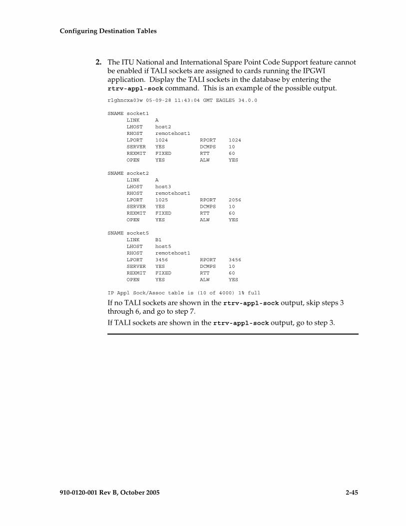
Configuring Destination Tables
910-0120-001 Rev B, October 2005 2-45
2. The ITU National and International Spare Point Code Support feature cannot be enabled if TALI sockets are assigned to cards running the IPGWI application. Display the TALI sockets in the database by entering the rtrv-appl-sock command. This is an example of the possible output.
rlghncxa03w 05-09-28 11:43:04 GMT EAGLE5 34.0.0
SNAME socket1 LINK A LHOST host2 RHOST remotehost1 LPORT 1024 RPORT 1024 SERVER YES DCMPS 10 REXMIT FIXED RTT 60 OPEN YES ALW YES
SNAME socket2 LINK A LHOST host3 RHOST remotehost1 LPORT 1025 RPORT 2056 SERVER YES DCMPS 10 REXMIT FIXED RTT 60 OPEN YES ALW YES
SNAME socket5 LINK B1 LHOST host5 RHOST remotehost1 LPORT 3456 RPORT 3456 SERVER YES DCMPS 10 REXMIT FIXED RTT 60 OPEN YES ALW YES
IP Appl Sock/Assoc table is (10 of 4000) 1% full
If no TALI sockets are shown in the rtrv-appl-sock output, skip steps 3 through 6, and go to step 7.
If TALI sockets are shown in the rtrv-appl-sock output, go to step 3.
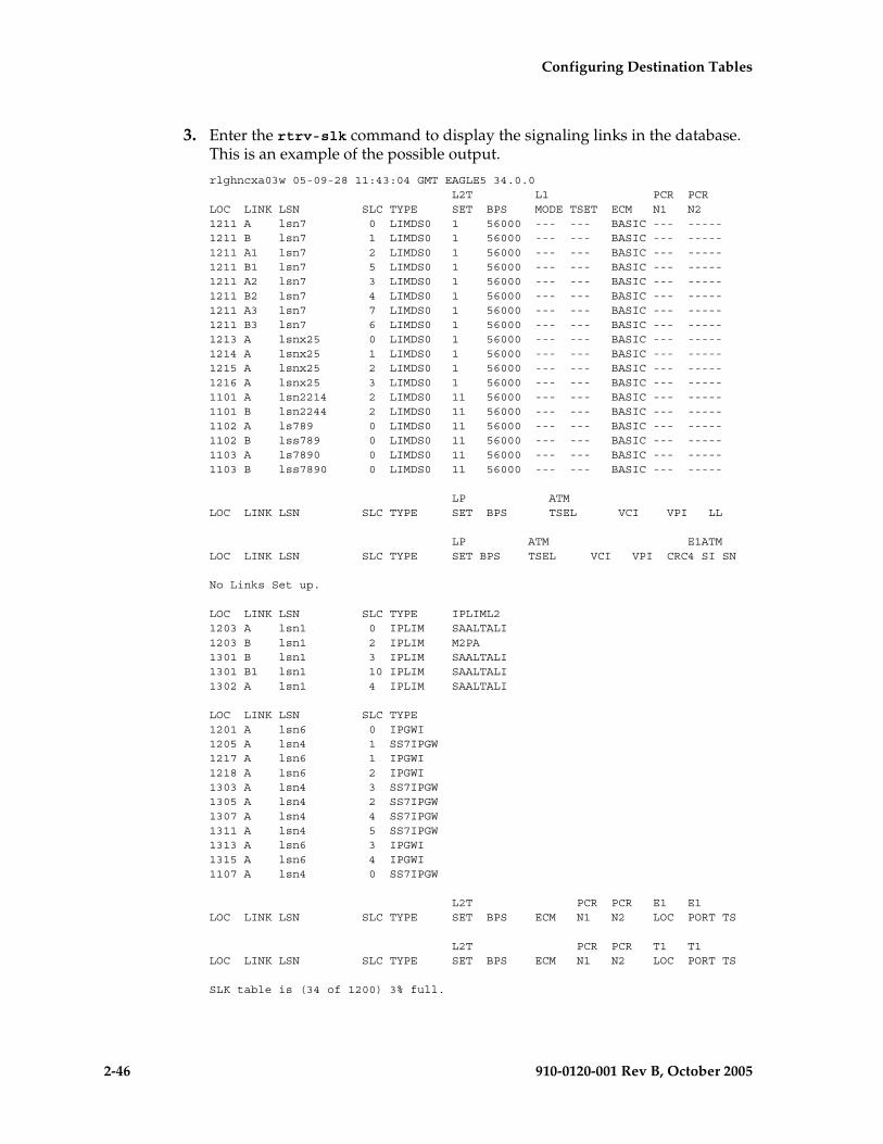
2-46 910-0120-001 Rev B, October 2005
Configuring Destination Tables
3. Enter the rtrv-slk command to display the signaling links in the database. This is an example of the possible output.
rlghncxa03w 05-09-28 11:43:04 GMT EAGLE5 34.0.0 L2T L1 PCR PCRLOC LINK LSN SLC TYPE SET BPS MODE TSET ECM N1 N21211 A lsn7 0 LIMDS0 1 56000 --- --- BASIC --- -----1211 B lsn7 1 LIMDS0 1 56000 --- --- BASIC --- -----1211 A1 lsn7 2 LIMDS0 1 56000 --- --- BASIC --- -----1211 B1 lsn7 5 LIMDS0 1 56000 --- --- BASIC --- -----1211 A2 lsn7 3 LIMDS0 1 56000 --- --- BASIC --- -----1211 B2 lsn7 4 LIMDS0 1 56000 --- --- BASIC --- -----1211 A3 lsn7 7 LIMDS0 1 56000 --- --- BASIC --- -----1211 B3 lsn7 6 LIMDS0 1 56000 --- --- BASIC --- -----1213 A lsnx25 0 LIMDS0 1 56000 --- --- BASIC --- -----1214 A lsnx25 1 LIMDS0 1 56000 --- --- BASIC --- -----1215 A lsnx25 2 LIMDS0 1 56000 --- --- BASIC --- -----1216 A lsnx25 3 LIMDS0 1 56000 --- --- BASIC --- -----1101 A lsn2214 2 LIMDS0 11 56000 --- --- BASIC --- -----1101 B lsn2244 2 LIMDS0 11 56000 --- --- BASIC --- -----1102 A ls789 0 LIMDS0 11 56000 --- --- BASIC --- -----1102 B lss789 0 LIMDS0 11 56000 --- --- BASIC --- -----1103 A ls7890 0 LIMDS0 11 56000 --- --- BASIC --- -----1103 B lss7890 0 LIMDS0 11 56000 --- --- BASIC --- -----
LP ATMLOC LINK LSN SLC TYPE SET BPS TSEL VCI VPI LL
LP ATM E1ATMLOC LINK LSN SLC TYPE SET BPS TSEL VCI VPI CRC4 SI SN
No Links Set up.
LOC LINK LSN SLC TYPE IPLIML21203 A lsn1 0 IPLIM SAALTALI1203 B lsn1 2 IPLIM M2PA1301 B lsn1 3 IPLIM SAALTALI1301 B1 lsn1 10 IPLIM SAALTALI1302 A lsn1 4 IPLIM SAALTALI
LOC LINK LSN SLC TYPE1201 A lsn6 0 IPGWI1205 A lsn4 1 SS7IPGW1217 A lsn6 1 IPGWI1218 A lsn6 2 IPGWI1303 A lsn4 3 SS7IPGW1305 A lsn4 2 SS7IPGW1307 A lsn4 4 SS7IPGW1311 A lsn4 5 SS7IPGW1313 A lsn6 3 IPGWI1315 A lsn6 4 IPGWI1107 A lsn4 0 SS7IPGW
L2T PCR PCR E1 E1LOC LINK LSN SLC TYPE SET BPS ECM N1 N2 LOC PORT TS
L2T PCR PCR T1 T1LOC LINK LSN SLC TYPE SET BPS ECM N1 N2 LOC PORT TS
SLK table is (34 of 1200) 3% full.
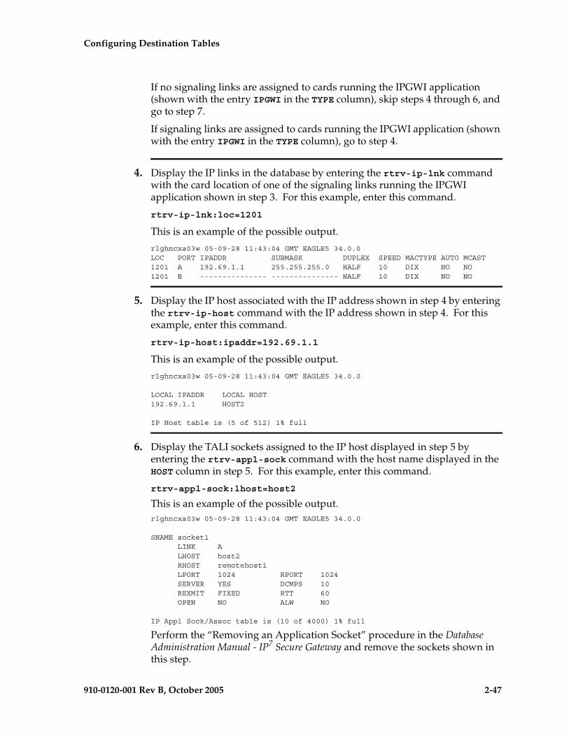
Configuring Destination Tables
910-0120-001 Rev B, October 2005 2-47
If no signaling links are assigned to cards running the IPGWI application (shown with the entry IPGWI in the TYPE column), skip steps 4 through 6, and go to step 7.
If signaling links are assigned to cards running the IPGWI application (shown with the entry IPGWI in the TYPE column), go to step 4.
4. Display the IP links in the database by entering the rtrv-ip-lnk command with the card location of one of the signaling links running the IPGWI application shown in step 3. For this example, enter this command.
rtrv-ip-lnk:loc=1201
This is an example of the possible output.
rlghncxa03w 05-09-28 11:43:04 GMT EAGLE5 34.0.0LOC PORT IPADDR SUBMASK DUPLEX SPEED MACTYPE AUTO MCAST1201 A 192.69.1.1 255.255.255.0 HALF 10 DIX NO NO1201 B --------------- --------------- HALF 10 DIX NO NO
5. Display the IP host associated with the IP address shown in step 4 by entering the rtrv-ip-host command with the IP address shown in step 4. For this example, enter this command.
rtrv-ip-host:ipaddr=192.69.1.1
This is an example of the possible output.
rlghncxa03w 05-09-28 11:43:04 GMT EAGLE5 34.0.0
LOCAL IPADDR LOCAL HOST192.69.1.1 HOST2
IP Host table is (5 of 512) 1% full
6. Display the TALI sockets assigned to the IP host displayed in step 5 by entering the rtrv-appl-sock command with the host name displayed in the HOST column in step 5. For this example, enter this command.
rtrv-appl-sock:lhost=host2
This is an example of the possible output.rlghncxa03w 05-09-28 11:43:04 GMT EAGLE5 34.0.0
SNAME socket1 LINK A LHOST host2 RHOST remotehost1 LPORT 1024 RPORT 1024 SERVER YES DCMPS 10 REXMIT FIXED RTT 60 OPEN NO ALW NO
IP Appl Sock/Assoc table is (10 of 4000) 1% full
Perform the “Removing an Application Socket” procedure in the Database Administration Manual - IP7 Secure Gateway and remove the sockets shown in this step.

2-48 910-0120-001 Rev B, October 2005
Configuring Destination Tables
If all the cards running the IPGWI application shown in the rtrv-slk output in step 3 have been checked for TALI socket assignments, go to step 7.
If all the cards running the IPGWI application shown in the rtrv-slk output in step 3 have not been checked for TALI socket assignments, repeat steps 4, 5, and 6.
NOTE: If the rtrv-ctrl-feat output in step 1 shows any controlled features, skip steps 7 through 10, and go to step 11. If the rtrv-ctrl-feat output shows only the IPGWx Signaling TPS feature with a quantity of 200 and the HC-MIM SLK Capacity feature with a quantity of 64, steps 7 through 10 must be performed.
7. Display the serial number in the database with the rtrv-serial-num command. This is an example of the possible output.
rlghncxa03w 05-09-28 21:15:37 GMT EAGLE5 34.0.0System serial number = nt00001231
System serial number is not locked.
rlghncxa03w 05-09-28 21:15:37 GMT EAGLE5 34.0.0Command Completed
NOTE: If the serial number is correct and locked, skip steps 8, 9, and 10, and go to step 11. If the serial number is correct but not locked, skip steps 8 and 9, and go to step 10. If the serial number is not correct, but is locked, this feature cannot be enabled and the remainder of this procedure cannot be performed. Contact the Customer Care Center to get an incorrect and locked serial number changed. Refer to “Customer Care Center” on page 1-8 for the contact information. The serial number can be found on a label affixed to the control shelf (shelf 1100).
8. Enter the correct serial number into the database using the ent-serial-num command with the serial parameter.
For this example, enter this command.ent-serial-num:serial=<EAGLE 5 SAS’s correct serial number>
When this command has successfully completed, the following message should appear.rlghncxa03w 05-09-28 21:15:37 GMT EAGLE5 34.0.0ENT-SERIAL-NUM: MASP A - COMPLTD

Configuring Destination Tables
910-0120-001 Rev B, October 2005 2-49
9. Verify that the serial number entered into step 8 was entered correctly using the rtrv-serial-num command. This is an example of the possible output.
rlghncxa03w 05-09-28 21:15:37 GMT EAGLE5 34.0.0System serial number = nt00001231
System serial number is not locked.
rlghncxa03w 05-09-28 21:15:37 GMT EAGLE5 34.0.0Command Completed
If the serial number was not entered correctly, repeat steps 3 and 4 and re-enter the correct serial number.
10. Lock the serial number in the database by entering the ent-serial-num command with the serial number shown in step 7, if the serial number shown in step 7 is correct, or with the serial number shown in step 9, if the serial number was changed in step 3, and with the lock=yes parameter.
For this example, enter this command.ent-serial-num:serial=<EAGLE 5 SAS’s serial number>:lock=yes
When this command has successfully completed, the following message should appear.rlghncxa03w 05-09-28 21:15:37 GMT EAGLE5 34.0.0ENT-SERIAL-NUM: MASP A - COMPLTD
11. Enable the ITU National and International Spare Point Code Support feature by entering the enable-ctrl-feat command. For this example, enter this command.
enable-ctrl-feat:partnum=893013601:fak=<ITU National and International Spare Point Code Support feature access key>
NOTE: The values for the feature access key (the fak parameter) are provided by Tekelec. If you do not have the feature access key for the ITU National and International Spare Point Code Support feature, contact your Tekelec Sales Representative or Account Representative.
When the enable-crtl-feat command has successfully completed, this message should appear.
rlghncxa03w 05-09-28 21:15:37 GMT EAGLE5 34.0.0ENABLE-CTRL-FEAT: MASP A - COMPLTD

2-50 910-0120-001 Rev B, October 2005
Configuring Destination Tables
12. Turn the ITU National and International Spare Point Code Support feature on by entering the chg-ctrl-feat command with the part number used in step 11 and the status=on parameter.
CAUTION: Once the ITU National and International Spare Point Code Support feature is turned on, it cannot be turned off.
For this example, enter this command.
chg-ctrl-feat:partnum=893013601:status=on
When this command has successfully completed, the following message should appear.
rlghncxa03w 05-09-28 21:15:37 GMT EAGLE5 34.0.0CHG-CTRL-FEAT: MASP A - COMPLTD
13. Verify the changes by entering the rtrv-ctrl-feat command. This is an example of the possible output.
rlghncxa03w 05-09-28 21:15:37 GMT EAGLE5 34.0.0The following features have been permanently enabled:
Feature Name Partnum Status QuantitySpare Point Code Support 893013601 on ----
The following features have been temporarily enabled:
Feature Name Partnum Status Quantity Trial Period LeftZero entries found.
The following features have expired temporary keys:
Feature Name PartnumZero entries found.
14. Back up the new changes, using the chg-db:action=backup:dest=fixed command. These messages should appear; the active Maintenance and Administration Subsystem Processor (MASP) appears first.
BACKUP (FIXED): MASP A - Backup starts on active MASP.BACKUP (FIXED): MASP A - Backup on active MASP to fixed disk complete.BACKUP (FIXED): MASP A - Backup starts on standby MASP.BACKUP (FIXED): MASP A - Backup on standby MASP to fixed disk complete.
15. To begin adding ITU-I or 14-bit ITU-N spare point codes, perform the “Adding a Point Code to the Self-Identification of the EAGLE 5 SAS” procedure on page 2-81.
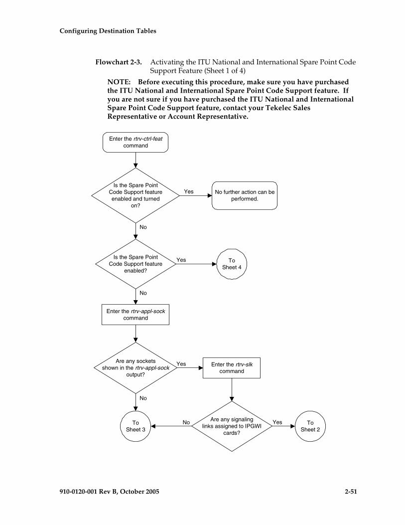
Configuring Destination Tables
910-0120-001 Rev B, October 2005 2-51
Flowchart 2-3. Activating the ITU National and International Spare Point Code Support Feature (Sheet 1 of 4)
NOTE: Before executing this procedure, make sure you have purchased the ITU National and International Spare Point Code Support feature. If you are not sure if you have purchased the ITU National and International Spare Point Code Support feature, contact your Tekelec Sales Representative or Account Representative.
Enter the rtrv-ctrl-featcommand
Yes
No
ToSheet 2
Is the Spare PointCode Support feature
enabled?
Yes
No
Is the Spare PointCode Support featureenabled and turned
on?
No further action can beperformed.
ToSheet 4
Enter the rtrv-slkcommand
Are any signalinglinks assigned to IPGWI
cards?
No YesToSheet 3
Enter the rtrv-appl-sockcommand
Are any socketsshown in the rtrv-appl-sock
output?
No
Yes

2-52 910-0120-001 Rev B, October 2005
Configuring Destination Tables
Flowchart 2-3. Activating the ITU National and International Spare Point Code Support Feature (Sheet 2 of 4)
FromSheet 1
Enter the rtrv-ip-lnk commandwith this parameter:
:loc = <IPGWI card locationshown in the rtrv-slk output
from Sheet 1>
Enter the rtrv-ip-hostcommand with this
parameter::ipaddr = <IP address shown
in the rtrv-ip-lnk output>
Enter the rtrv-appl-sockcommand with this
parameter::lhost = <host name shown in
the rtrv-ip-host output>
Perform the "Removing anApplication Socket" procedure in
the Database AdministrationManual - IP7 Secure Gateway
and remove the sockets shownin the rtrv-appl-sock output.
Have all the IPGWIcards shown in the rtrv-slk output
on Sheet 1 been checked forsocket assignments?
ToSheet 3
No
Yes

Configuring Destination Tables
910-0120-001 Rev B, October 2005 2-53
Flowchart 2-3. Activating the ITU National and International Spare Point Code Support Feature (Sheet 3 of 4)

2-54 910-0120-001 Rev B, October 2005
Configuring Destination Tables
Flowchart 2-3. Activating the ITU National and International Spare Point Code Support Feature (Sheet 4 of 4)
Configuring Destination Tables
910-0120-001 Rev B, October 2005 2-55
Multiple Point Code Support
Currently, the EAGLE 5 SAS supports six true point codes:
• ANSI point code
• ITU international point code
• ITU international spare point code
• 14-bit ITU national point code
• 14-bit ITU national spare point code
• 24-bit ITU national point code.
NOTE: The ITU national point code can be either 14-bit ITU national - spare and non-spare - or 24-bit ITU national. Both 14-bit ITU national and 24-bit national point codes cannot be present in the EAGLE 5 SAS at the same time.
In addition, the EAGLE 5 SAS supports up to 96 capability point codes, each of which can be designated as either ANSI, ITU-I (spare and non-spare), 14-bit ITU-N (spare and non-spare), or 24-bit ITU-N. Each capability point code defined on an EAGLE 5 SAS node can be used for routing messages to that node. For various reasons, customers might need the EAGLE 5 SAS to support more than one true point code in a particular domain.
There are three main reasons driving this feature:
1. Some customers desire to collapse multiple existing STP's into one EAGLE 5 SAS. This can present problems in that end offices and other nodes may not be controlled by the carrier making reprovisioning of these network elements difficult. Multiple Point Code (MPC) support is designed to allow the EAGLE 5 SAS to assume more than one point code for SS7 routing. MPC support is different in concept from capability point codes in that provisioning and routing will use secondary point codes as if they were the actual point code of the EAGLE 5 SAS.
2. Several customers in the international market want to deploy a single STP pair in multiple national (ITU-N) networks. This may not be possible without the MPC feature, as these operators are often forced to use a unique point code assigned by each national regulator of these target countries.
3. Customers may require additional links between two nodes beyond the number of links permitted by the protocol. For example, the maximum number of links between two nodes in an ITU network is 16. The MPC feature can allow for additional linksets between these nodes, increasing the number of links that can be used.

2-56 910-0120-001 Rev B, October 2005
Configuring Destination Tables
This feature adds the ability to support Secondary Point Codes (SPCs) in addition to the true point codes used by the EAGLE 5 SAS in any of the three domains ANSI, ITU-N (14-bit or 24-bit) and ITU-I. Secondary point codes are used by provisioning and routing as if they are the true point code of the EAGLE 5 SAS. SPCs are supported for any type of link (A, B, C, D, etc.). There is no effect on provisioning capability point codes as a result of this feature.
In addition to the one True Point Code (TPC) already supported for each of the ANSI, ITU-N (14-bit or 24-bit) and ITU-I domains, the EAGLE 5 SAS support a pool of 40 Secondary Point Codes (SPC), each of which may be assigned as either ANSI, ITU-I, 14-bit ITU-N, or 24-bit ITU-N (not to exceed a total of 40 in one EAGLE 5 SAS). SPCs can be used in the same ways that true PCs are used.
Replacing Two STP Pairs with One Pair
The following example shows how an EAGLE 5 SAS pair can replace two existing STP pairs. In this example, each EAGLE 5 SAS in the pair uses one true point code and one secondary point code.
As shown in Figure 2-5, a new EAGLE 5 SAS first replaces one existing STP pair. In this case, EAGLE 5 SAS's true point code is set to the true point code of the old STP. The adjacent nodes are cut over to the EAGLE 5 SAS pair. The adjacent nodes do not need to be reconfigured.
Figure 2-5. Replacing the First STP Pair
Configuring Destination Tables
910-0120-001 Rev B, October 2005 2-57
Next, a second STP pair is replaced with the EAGLE 5 SAS pair. As shown in Figure 2-6 on page 2-58, an SSP and an STP are being “re-homed” from an old STP pair to a new EAGLE 5 SAS pair. In this example, the STP (003-003-003) is reconfigured with new routes to recognize that it is now connected to EAGLE 5 SAS 1 and EAGLE 5 SAS 2 instead of 001-001-001 and 001-001-002. STP 003-003-003, if not an EAGLE 5 SAS with Multiple Point Codes, may not be able to support more than one linkset to the same point code. See the “Multiple Linksets between Two Nodes” section on page 2-58 for a description of this capability. The interconnecting device (STP or SSP) can use either the TPC or SPC as the device requires.
At EAGLE 5 SAS 1, the user would configure the secondary point code 001-001-001, using the ent-spc command. The user would also configure a route to 001-001-002 over the C-linkset. The user would then configure point code 004-004-004 in the EAGLE 5 SAS's database to indicate that this point code uses the secondary point code 001-001-001, instead of the EAGLE 5 SAS's true point code (chg-dstn:dpc=004-004-004:spc=001-001-001. This last step would be repeated for all other adjacent SSPs and SCPs that are re-homed from the old STP Pair to the new EAGLE 5 SAS Pair.
Similarly, at EAGLE 5 SAS 2, the user would configure the secondary point code 001-001-002, and configure a route over the C-link to 001-001-001. The user would also configure point code 004-004-004 in EAGLE 5 SAS 2's database to indicate that this point code uses the secondary point code 001-001-002, instead of the EAGLE 5 SAS's true point code.
When EAGLE 5 SAS 1 receives a message from the SSP destined for 001-001-001, the EAGLE 5 SAS processes the message as if the message was sent to the EAGLE 5 SAS's true point code.
When EAGLE 5 SAS 1 generates a message (for example, network management, link test messages, or GTT messages) that is destined for 004-004-004, EAGLE 5 SAS 1 puts the OPC 001-001-001 in the message. When EAGLE 5 SAS 1 generates a message that is destined for 003-003-003 or 005-005-005, it puts the OPC 002-002-001 in the message. When EAGLE 5 SAS 1 generates GTT and SCMG messages that are destined for non-adjacent point codes, it includes the OPC 002-002-001 in the message.

2-58 910-0120-001 Rev B, October 2005
Configuring Destination Tables
Figure 2-6. Replacing a Second STP Pair
Multiple Linksets between Two Nodes
With this feature, it is possible to configure multiple linksets between two nodes, if the adjacent node also supports Multiple Point Codes. The EAGLE 5 SAS continues to enforce the rule that each linkset must have a different adjacent point code.
One reason for provisioning multiple linksets between two nodes is to increase the number of links that can be configured between STP pairs. For example, in Figure 2-7, the EAGLE 5 SAS is connected to an STP pair that supports multiple point codes. Without this feature, only 16 ITU links can be configured between the EAGLE 5 SAS and the STP pair (8 links in LS1 and 8 links in LS2). In this example, two linksets are added, increasing the number of links to 32 (8 links in each of LS1, LS2, LS3, and LS4).

Configuring Destination Tables
910-0120-001 Rev B, October 2005 2-59
Figure 2-7. Multiple Linkset Example
In this example, the adjacent point code (APC) for LS1 is 4-1-0 and the APC for LS2 is 4-1-1. 4-1-1 is assigned an SPC of 3-1-1. So adjacent, Adj Node1 sees LS1 as having an APC of 3-1-0, and LS2 as having an APC of 3-1-1.
To load balance over these 4 linksets, half the destinations that use the STP pair can be assigned LS1 and LS3 as a combined linkset. The other half of the destinations can be assigned LS2 and LS4 as a combined linkset.
The commands to provision EAGLE 5 SAS1 for the network shown in Figure 2-7 are:
chg-sid:pc=3-1-0
ent-spc=3-1-1
ent-dstn:dpc=4-1-0
ent-dstn:dpc=4-1-1:spc=3-1-1
ent-dstn:dpc=4-1-5
ent-dstn:dpc=4-1-6:spc=3-1-1
ent-dstn:dpc=5-5-1
ent-dstn:dpc=5-5-5
ent-ls:lsn=ls1:apc=4-1-0
ent-ls:lsn=ls2:apc=4-1-1
ent-ls: lsn=ls3:apc=4-1-5
ent-ls: lsn=ls4:apc=4-1-6
ent-rte:dpc=4-1-0:lsn=ls1:rc=10
ent-rte:dpc=4-1-1:lsn=ls2:rc=10
ent-rte:dpc=4-1-5:lsn=ls3:rc=10
ent-rte:dpc=4-1-6:lsn=ls4:rc=10
ent-rte:dpc=5-5-1:lsn=ls1:rc=10
ent-rte:dpc=5-5-1:lsn=ls3:rc=10
2-60 910-0120-001 Rev B, October 2005
Configuring Destination Tables
ent-rte:dpc=5-5-5:lsn=ls2:rc=10
ent-rte:dpc=5-5-5:lsn=ls4:rc=10
Local Number Portability
NOTE: Local number portability supports only ANSI point codes.
The EAGLE 5 SAS allows only the true point code to be entered into the mated application table. Also, the EAGLE 5 SAS continues to allow the user to enter translations to the true point code. However, the EAGLE 5 SAS does not allow the user to enter translation to a secondary point code.
If a node sends a rt-on-gt query, the node should set the query's DPC to the EAGLE 5 SAS's capability point code. If a node sends an rt-on-ssn query, the node should set the query's DPC to the true point code or secondary point code used by that node. If the node has a secondary point code, then the query’s DPC is set to the secondary point code. If the node does not have a secondary point code, then the query’s DPC is set to the true point code.
rt-on-gt Queries from a Node That Uses Secondary Point Codes
Nodes that send rt-on-gt queries should use the capability point code, regardless of whether these nodes use a true or a secondary point code.
1. The node sends a query containing this information:
– The DPC is the capability point code of the EAGLE 5 SAS's LNP subsystem.
– The routing indicator in the called party address is GT.
– The point code in the calling party address is the node's point code.
2. The result of the translation contains this information:
– The DPC is the EAGLE 5 SAS’s true point code.
– The routing indicator in the called party address is SSN.
– The subsystem number in the calling party address is the LNP subsystem number.
3. The LNP subsystem sends a reply with this information:
– The DPC is the calling party address’ point code.
– The OPC is the EAGLE 5 SAS’s secondary point code.
– The routing indicator in the called party address is SSN.

Configuring Destination Tables
910-0120-001 Rev B, October 2005 2-61
In this case, if the local subsystem fails or is taken offline, the EAGLE 5 SAS sends a response method TFP containing this information:
• The DPC is the node's point code.
• The OPC is the EAGLE 5 SAS’s secondary point code.
• The concerned point code is the EAGLE 5 SAS's capability point code.
This TFP causes the node to divert traffic to the mate.
If a node sends an rt-on-gt query to either the EAGLE 5 SAS's true point code or a secondary point code, the EAGLE 5 SAS cannot divert traffic to the mate. In this case, the EAGLE 5 SAS does not send a TFP concerning the secondary point code or the true point code, so the node will not divert traffic to the mate.
rt-on-ssn queries from a Node That Uses Secondary Point Codes
It is possible that nodes using a secondary point code will send rt-on-ssn queries. In this case, these nodes should send the queries to the secondary point code. The EAGLE 5 SAS will accept rt-on-ssn queries from these nodes if the DPC is the true point code or a secondary point code. However, SCCP management will not work correctly if the rt-on-ssn queries do not use the true point code or a secondary point code associated with the sending node.
1. Nodes send queries to the EAGLE 5 SAS with this information:
– The DPC is the EAGLE 5 SAS’s secondary point code.
– The routing indicator in the called party address is SSN.
– The subsystem number in the called party address is the LNP subsystem number.
– The subsystem number is the LNP subsystem number.
– The point code in the calling party address is the node's point code.
2. The LNP subsystem sends a reply with this information:
– The DPC is the point code in the calling party address.
– The OPC is the secondary point code.
– The routing indicator in the called party address is SSN.
– The point code in the calling party address is the secondary point code.
2-62 910-0120-001 Rev B, October 2005
Configuring Destination Tables
In this case, if the EAGLE 5 SAS’s LNP subsystem fails or is taken offline, the EAGLE 5 SAS broadcasts an SSP (assuming that the node is in the concerned point code group) with this information:
• The DPC is the node's point code.
• The OPC is the secondary point code.
• The affected point code is the secondary point code.
• The affected subsystem number is the LNP subsystem number.
Limitations
1. The same adjacent point code cannot be used for two different links.
2. Local EAGLE 5 SAS subsystems (for example, LNP) must use the True Point Code.

Configuring Destination Tables
910-0120-001 Rev B, October 2005 2-63
Adding a Secondary Point Code
This procedure is used to add a secondary point code to the database using the ent-spc command.
The ent-spc command uses only one parameter: spc/spca/spci/spcn/spcn24 – the secondary point code.
NOTE: See “Point Code Formats” on page 2-4 for a definition of the point code types that are used on the EAGLE 5 SAS and for a definition of the different formats that can be used for ITU national point codes.
The secondary point code must be a full point code. Cluster and network routing point codes cannot be specified as a secondary point code.
The Multiple Point Code Support feature must be on to configure secondary point codes in the database. This can be verified with the entry MPC = on in the rtrv-feat command output. If the Multiple Point Code Support feature is not turned on, enter the chg-feat:mpc=on command.
NOTE: Once the Multiple Point Code Support feature is turned on with the chg-feat command, it cannot be turned off.
The Multiple Point Code Support feature must be purchased before you turn this feature on with the chg-feat command. If you are not sure if you have purchased the Multiple Point Code Support feature, contact your Tekelec Sales Representative or Account Representative.
The database can contain up to 40 secondary point codes.
The secondary point code cannot be defined in the database as the true point code of the EAGLE 5 SAS, a capability point code, a destination point code, or an alias point code. The true point code and capability point codes are shown in the rtrv-sid command output. The destination point codes and alias point codes are shown in the rtrv-dstn command output.
For the examples in this procedure, these secondary point codes are being added to the database:
ANSI secondary point code = 010-100-010
ITU secondary international point code = 4-100-1
14-bit ITU secondary national point code = 14-15-12-1
The format of the 14-bit ITU national point codes used in these examples is 4-4-4-2.

2-64 910-0120-001 Rev B, October 2005
Configuring Destination Tables
Canceling the RTRV-DSTN Command
Because the rtrv-dstn command used in this procedure can output information for a long period of time, the rtrv-dstn commands can be canceled and the output to the terminal stopped. There are three ways that the rtrv-dstn command can be canceled:
• Press the F9 function key on the keyboard at the terminal where the rtrv-dstn command was entered.
• Enter the canc-cmd without the trm parameter at the terminal where the rtrv-dstn command was entered.
• Enter the canc-cmd:trm=<xx>, where <xx> is the terminal where the rtrv-dstn command was entered, from another terminal other than the terminal where the rtrv-dstn command was entered. To enter the canc-cmd:trm=<xx> command, the terminal must allow Security Administration commands to be entered from it and the user must be allowed to enter Security Administration commands. The terminal’s permissions can be verified with the rtrv-secu-trm command. The user’s permissions can be verified with the rtrv-user or rtrv-secu-user commands.
For more information about the canc-cmd command, refer to the Commands Manual.
Procedure
1. Display the current secondary point codes, using the rtrv-spc command. This is an example of the possible output.
rlghncxa03w 05-09-17 16:02:05 GMT EAGLE5 34.0.0SPC (Secondary Point Codes)
SPCA 001-010-010 002-010-010 003-010-010
SPC-I 1-253-5 2-254-6 3-255-7
SPC-N 10-01-11-1 13-02-12-0
SPC-N24
none
Secondary Point Code table is (8 of 40) 20% full

Configuring Destination Tables
910-0120-001 Rev B, October 2005 2-65
If the secondary point code table is full, shown by the entry Secondary Point Code table is (40 of 40) 100% full, go to the “Removing a Secondary Point Code” procedure on page 2-74 and remove a secondary point code from the database.
If error message E3867 Cmd Rej: MPC feature must be enabled is displayed, the EAGLE 5 SAS has detected that the multiple point code support feature is off and the rtrv-spc command will not display any data. Go to step 2 and verify that the multiple point code support feature is off.
2. Verify whether or not the multiple point code support feature is on, by entering the rtrv-feat command. If the multiple point code support feature is on, the MPC field should be set to on. For this example, the multiple point code support feature is off.
NOTE: The rtrv-feat command output contains other fields that are not used by this procedure. If you wish to see all the fields displayed by the rtrv-feat command, see the rtrv-feat command description in the Commands Manual.
If the multiple point code support feature is on, skip step 3 and go to step 6.
If the rtrv-feat command output shows that the multiple point code support feature is on, but error message E3867 was displayed when the rtrv-spc command was entered, contact the Customer Care Center. Refer to “Customer Care Center” on page 1-8 for the contact information.
If group codes are to be assigned to the ITU-N secondary point code, and none are currently displayed in the rtrv-spc command output, the ITU National Duplicate Point Code feature must be on. This is shown by the entry ITUDUPPC = on in the rtrv-feat command output.
3. Turn the multiple point code support feature on by entering this command.
chg-feat:mpc=on
NOTE: Once the multiple point code support feature is turned on with the chg-feat command, it cannot be turned off.
The multiple point code support feature must be purchased before you turn this feature on with the chg-feat command. If you are not sure if you have purchased the multiple point code support feature, contact your Tekelec Sales Representative or Account Representative.
When the chg-feat has successfully completed, this message should appear.
rlghncxa03w 05-09-07 00:57:31 GMT EAGLE5 34.0.0CHG-FEAT: MASP A - COMPLTD

2-66 910-0120-001 Rev B, October 2005
Configuring Destination Tables
NOTE: If group codes are shown for the 14-bit ITU-N secondary point codes in the rtrv-spc command output, if 24-bit ITU-N secondary point codes are being configured, or the ITU National Duplicate Point Code feature is on, skip this step and go to step 5.
4. Turn the ITU National Duplicate Point Code feature on by entering this command.
chg-feat:ituduppc=on
NOTE: Once the ITU National Duplicate Point Code feature is turned on with the chg-feat command, it cannot be turned off.
NOTE: The ITU National Duplicate Point Code feature must be purchased before you turn this feature on with the chg-feat command. If you are not sure if you have purchased the ITU National Duplicate Point Code feature, contact your Tekelec Sales Representative or Account Representative.
When the chg-feat has successfully completed, this message should appear.
rlghncxa03w 05-09-07 00:57:31 GMT EAGLE5 34.0.0CHG-FEAT: MASP A - COMPLTD
5. Display the self-identification of the EAGLE 5 SAS using the rtrv-sid command to verify the point code values in the self-identification of the EAGLE 5 SAS, and to verify the point code types defined in the EAGLE 5 SAS. This is an example of the possible output.
rlghncxa03w 05-09-10 11:43:04 GMT EAGLE5 34.0.0 PCA PCI PCN CLLI PCTYPE 100-100-100 3-75-7 7-9-8-1 rlghncxa03w OTHER CPCA 002-002-002 002-002-003 002-002-004 002-002-005 002-002-006 002-002-007 002-002-008 002-002-009 004-002-001 004-003-003 050-060-070 CPCA (LNP) 005-005-002 005-005-004 005-005-005 CPCI 1-002-1 1-002-2 1-002-3 1-002-4 2-001-1 7-222-7 CPCN 2-0-10-3 2-0-11-0 2-0-11-2 2-0-12-1 2-2-3-3 2-2-4-0 10-14-10-1
To enter an ANSI secondary code with the ent-spc command, a point code must be shown in the PCA field of the rtrv-sid command output.
To enter an ITU-I secondary point code with the ent-spc command, a point code must be shown in the PCI field of the rtrv-sid command output.
To enter a 14-bit ITU-N secondary point code with the ent-spc command, a point code must be shown in the PCN field of the rtrv-sid command output.
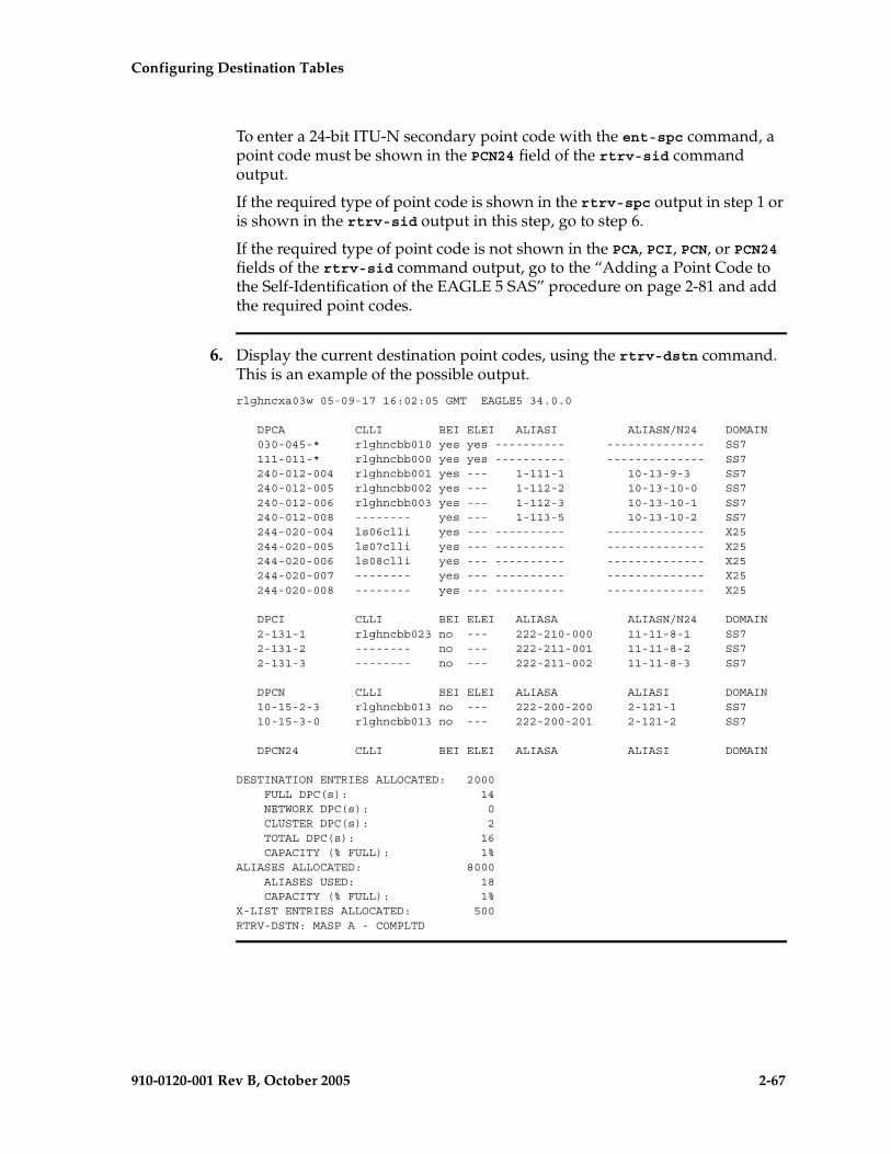
Configuring Destination Tables
910-0120-001 Rev B, October 2005 2-67
To enter a 24-bit ITU-N secondary point code with the ent-spc command, a point code must be shown in the PCN24 field of the rtrv-sid command output.
If the required type of point code is shown in the rtrv-spc output in step 1 or is shown in the rtrv-sid output in this step, go to step 6.
If the required type of point code is not shown in the PCA, PCI, PCN, or PCN24 fields of the rtrv-sid command output, go to the “Adding a Point Code to the Self-Identification of the EAGLE 5 SAS” procedure on page 2-81 and add the required point codes.
6. Display the current destination point codes, using the rtrv-dstn command. This is an example of the possible output.
rlghncxa03w 05-09-17 16:02:05 GMT EAGLE5 34.0.0
DPCA CLLI BEI ELEI ALIASI ALIASN/N24 DOMAIN 030-045-* rlghncbb010 yes yes ---------- -------------- SS7 111-011-* rlghncbb000 yes yes ---------- -------------- SS7 240-012-004 rlghncbb001 yes --- 1-111-1 10-13-9-3 SS7 240-012-005 rlghncbb002 yes --- 1-112-2 10-13-10-0 SS7 240-012-006 rlghncbb003 yes --- 1-112-3 10-13-10-1 SS7 240-012-008 -------- yes --- 1-113-5 10-13-10-2 SS7 244-020-004 ls06clli yes --- ---------- -------------- X25 244-020-005 ls07clli yes --- ---------- -------------- X25 244-020-006 ls08clli yes --- ---------- -------------- X25 244-020-007 -------- yes --- ---------- -------------- X25 244-020-008 -------- yes --- ---------- -------------- X25
DPCI CLLI BEI ELEI ALIASA ALIASN/N24 DOMAIN 2-131-1 rlghncbb023 no --- 222-210-000 11-11-8-1 SS7 2-131-2 -------- no --- 222-211-001 11-11-8-2 SS7 2-131-3 -------- no --- 222-211-002 11-11-8-3 SS7
DPCN CLLI BEI ELEI ALIASA ALIASI DOMAIN 10-15-2-3 rlghncbb013 no --- 222-200-200 2-121-1 SS7 10-15-3-0 rlghncbb013 no --- 222-200-201 2-121-2 SS7
DPCN24 CLLI BEI ELEI ALIASA ALIASI DOMAIN
DESTINATION ENTRIES ALLOCATED: 2000 FULL DPC(s): 14 NETWORK DPC(s): 0 CLUSTER DPC(s): 2 TOTAL DPC(s): 16 CAPACITY (% FULL): 1%ALIASES ALLOCATED: 8000 ALIASES USED: 18 CAPACITY (% FULL): 1%X-LIST ENTRIES ALLOCATED: 500RTRV-DSTN: MASP A - COMPLTD
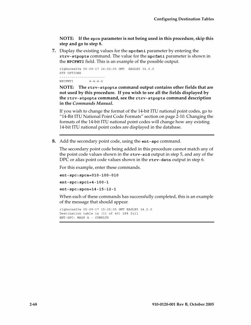
2-68 910-0120-001 Rev B, October 2005
Configuring Destination Tables
NOTE: If the spcn parameter is not being used in this procedure, skip this step and go to step 8.
7. Display the existing values for the npcfmti parameter by entering the rtrv-stpopts command. The value for the npcfmti parameter is shown in the NPCFMTI field. This is an example of the possible output.
rlghncxa03w 05-09-17 16:02:05 GMT EAGLE5 34.0.0STP OPTIONS-----------------------NPCFMTI 4-4-4-2
NOTE: The rtrv-stpopts command output contains other fields that are not used by this procedure. If you wish to see all the fields displayed by the rtrv-stpopts command, see the rtrv-stpopts command description in the Commands Manual.
If you wish to change the format of the 14-bit ITU national point codes, go to “14-Bit ITU National Point Code Formats” section on page 2-10. Changing the formats of the 14-bit ITU national point codes will change how any existing 14-bit ITU national point codes are displayed in the database.
8. Add the secondary point code, using the ent-spc command.
The secondary point code being added in this procedure cannot match any of the point code values shown in the rtrv-sid output in step 5, and any of the DPC or alias point code values shown in the rtrv-dstn output in step 6.
For this example, enter these commands.
ent-spc:spca=010-100-010
ent-spc:spci=4-100-1
ent-spc:spcn=14-15-12-1
When each of these commands has successfully completed, this is an example of the message that should appear.
rlghncxa03w 05-09-17 15:35:05 GMT EAGLE5 34.0.0Destination table is (11 of 40) 28% fullENT-SPC: MASP A - COMPLTD

Configuring Destination Tables
910-0120-001 Rev B, October 2005 2-69
9. Verify the changes using the rtrv-spc command. This is an example of the possible output.
rlghncxa03w 05-09-17 16:02:05 GMT EAGLE5 34.0.0SPC (Secondary Point Codes)
SPCA 001-010-010 002-010-010 003-010-010 010-100-010
SPC-I 1-253-5 2-254-6 3-255-7 4-100-1
SPC-N 10-01-11-1 13-02-12-0 14-15-12-1
SPC-N24
none
Secondary Point Code table is (11 of 40) 28% full
10. Back up the new changes, using the chg-db:action=backup:dest=fixed command. These messages should appear; the active Maintenance and Administration Subsystem Processor (MASP) appears first.
BACKUP (FIXED) : MASP A - Backup starts on active MASP.BACKUP (FIXED) : MASP A - Backup on active MASP to fixed disk complete.BACKUP (FIXED) : MASP A - Backup starts on standby MASP.BACKUP (FIXED) : MASP A - Backup on standby MASP to fixed disk complete.

2-70 910-0120-001 Rev B, October 2005
Configuring Destination Tables
Flowchart 2-4. Adding a Secondary Point Code (Sheet 1 of 4)
NOTE: Before executing this procedure, make sure you have purchased the Multiple Point Code Support feature, and if you are assigning a group code to a 14-bit ITU-N secondary point code, the Duplicate ITU-N Point Code Support feature. If you are not sure if you have purchased these features, contact your Tekelec Sales Representative or Account Representative.

Configuring Destination Tables
910-0120-001 Rev B, October 2005 2-71
Flowchart 2-4. Adding a Secondary Point Code (Sheet 2 of 4)
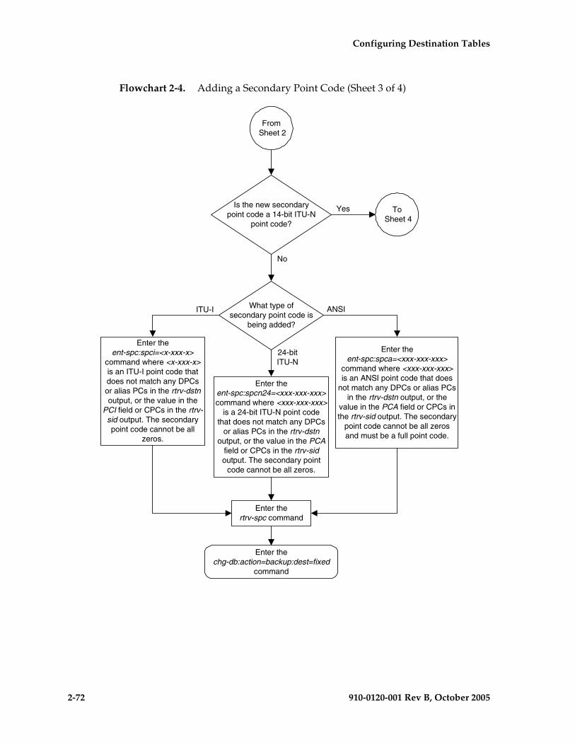
2-72 910-0120-001 Rev B, October 2005
Configuring Destination Tables
Flowchart 2-4. Adding a Secondary Point Code (Sheet 3 of 4)
What type ofsecondary point code is
being added?
Is the new secondarypoint code a 14-bit ITU-N
point code?
Yes
No
Enter theent-spc:spci=<x-xxx-x>
command where <x-xxx-x>is an ITU-I point code thatdoes not match any DPCsor alias PCs in the rtrv-dstnoutput, or the value in the
PCI field or CPCs in the rtrv-sid output. The secondarypoint code cannot be all
zeros.
ITU-I ANSI
Enter thertrv-spc command
From Sheet 2
To Sheet 4
Enter theent-spc:spca=<xxx-xxx-xxx>
command where <xxx-xxx-xxx>is an ANSI point code that does
not match any DPCs or alias PCsin the rtrv-dstn output, or the
value in the PCA field or CPCs inthe rtrv-sid output. The secondary
point code cannot be all zerosand must be a full point code.
Enter thechg-db:action=backup:dest=fixed
command
Enter theent-spc:spcn24=<xxx-xxx-xxx>command where <xxx-xxx-xxx>
is a 24-bit ITU-N point codethat does not match any DPCs
or alias PCs in the rtrv-dstnoutput, or the value in the PCA
field or CPCs in the rtrv-sidoutput. The secondary point
code cannot be all zeros.
24-bitITU-N
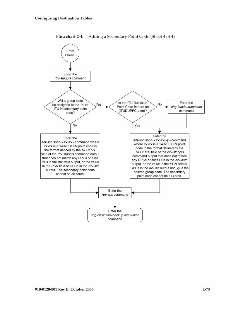
Configuring Destination Tables
910-0120-001 Rev B, October 2005 2-73
Flowchart 2-4. Adding a Secondary Point Code (Sheet 4 of 4)
Is the ITU DuplicatePoint Code feature on(ITUDUPPC = on)?
Will a group codebe assigned to the 14-bitITU-N secondary point
code?
Yes
No
Enter thertrv-spc command
From Sheet 3
Enter theent-spc:spcn=<xxxxx-yy> commandwhere xxxxx is a 14-bit ITU-N pointcode in the format defined by theNPCFMTI field of the rtrv-stpopts
command output that does not matchany DPCs or alias PCs in the rtrv-dstnoutput, or the value in the PCN field or
CPCs in the rtrv-sid output and yy is thedesired group code. The secondary
point code cannot be all zeros.
Enter thechg-db:action=backup:dest=fixed
command
Enter thertrv-stpopts command
Enter thechg-feat:ituduppc=on
command
Enter theent-spc:spcn=<xxxxx> command where
xxxxx is a 14-bit ITU-N point code inthe format defined by the NPCFMTI
field of the rtrv-stpopts command outputthat does not match any DPCs or aliasPCs in the rtrv-dstn output, or the valuein the PCN field or CPCs in the rtrv-sid
output. The secondary point codecannot be all zeros.
Yes
No
2-74 910-0120-001 Rev B, October 2005
Configuring Destination Tables
Removing a Secondary Point Code
This procedure is used to remove a secondary point code from the database using the dlt-spc command.
The dlt-spc command uses only one parameter: spc/spca/spci/spcn/spcn24 – the secondary point code.
NOTE: See “Point Code Formats” on page 2-4 for a definition of the point code types that are used on the EAGLE 5 SAS and for a definition of the different formats that can be used for ITU national point codes.
The secondary point code being removed from the database must be in the database, but cannot be referenced by any destination point codes. Entering the rtrv-dstn command with either the spca, spci, spcn, or spcn24, depending on the point code type of the secondary point code being removed from the database, shows the destination point codes that are referencing the secondary point code being removed from the database.
For the example in this procedure, secondary point code 010-100-010 is being removed from the database.
Canceling the RTRV-DSTN Command
Because the rtrv-dstn command used in this procedure can output information for a long period of time, the rtrv-dstn commands can be canceled and the output to the terminal stopped. There are three ways that the rtrv-dstn command can be canceled:
• Press the F9 function key on the keyboard at the terminal where the rtrv-dstn command was entered.
• Enter the canc-cmd without the trm parameter at the terminal where the rtrv-dstn command was entered.
• Enter the canc-cmd:trm=<xx>, where <xx> is the terminal where the rtrv-dstn command was entered, from another terminal other than the terminal where the rtrv-dstn command was entered. To enter the canc-cmd:trm=<xx> command, the terminal must allow Security Administration commands to be entered from it and the user must be allowed to enter Security Administration commands. The terminal’s permissions can be verified with the rtrv-secu-trm command. The user’s permissions can be verified with the rtrv-user or rtrv-secu-user commands.
For more information about the canc-cmd command, refer to the Commands Manual.

Configuring Destination Tables
910-0120-001 Rev B, October 2005 2-75
Procedure
1. Display the secondary point codes in the database, using the rtrv-spc command. This is an example of the possible output.
rlghncxa03w 05-09-17 16:02:05 GMT EAGLE5 34.0.0SPC (Secondary Point Codes)
SPCA 001-010-010 002-010-010 003-010-010 010-100-010
SPC-I 1-253-5 2-254-6 3-255-7 4-100-1
SPC-N 10-01-11-1 13-02-12-0 14-15-12-1
SPC-N24
none
Secondary Point Code table is (11 of 40) 28% full
2. Display the destination point codes that reference the secondary point code being removed from the database using the rtrv-dstn command with either the spca, spci, or spcn parameters.
For this example, enter this command.
rtrv-dstn:spca=010-100-010
This is an example of the possible output.
rlghncxa03w 05-09-17 16:02:05 GMT EAGLE5 34.0.0
DPCA CLLI BEI ELEI ALIASI ALIASN/N24 DOMAIN 240-012-004 rlghncbb001 yes --- 1-111-1 10-13-9-3 SS7
SPC NCAI 010-100-010 no
240-012-005 rlghncbb002 yes --- 1-112-2 10-13-10-0 SS7
SPC NCAI 010-100-010 no
Destination table is (16 of 2000) 1% full Alias table is (9 of 8000) 1% fullRTRV-DSTN: MASP A - COMPLTD

2-76 910-0120-001 Rev B, October 2005
Configuring Destination Tables
3. Remove the reference to the secondary point code using the chg-dstn command and specifying the destination point codes shown in step 2 with either the dpca, dpci, or dpcn parameters, and with either the spca=none, spci=none, or spcn=none parameters, depending on the type of point codes being used. For this example, enter these commands.
chg-dstn:dpca=240-012-004:spca=none
chg-dstn:dpca=240-012-005:spca=none
When this command has successfully completed, and the cluster routing and management diversity feature is turned off (CRMD = off in the rtrv-feat command output), this message should appear.
rlghncxa03w 05-09-17 15:35:05 GMT EAGLE5 34.0.0Destination table is (16 of 2000) 1% fullCHG-DSTN: MASP A - COMPLTD
If the cluster routing and management diversity feature is turned on (CRMD = on in the rtrv-feat command output), this message should appear when each command has successfully completed.
rlghncxa03w 05-09-17 15:35:05 GMT EAGLE5 34.0.0DESTINATION ENTRIES ALLOCATED: 2000 FULL DPC(s): 14 NETWORK DPC(s): 0 CLUSTER DPC(s): 2 TOTAL DPC(s): 16 CAPACITY (% FULL): 1%ALIASES ALLOCATED: 8000 ALIASES USED: 8 CAPACITY (% FULL): 1%X-LIST ENTRIES ALLOCATED: 500CHG-DSTN: MASP A - COMPLTD
4. Remove the secondary point code, using the dlt-spc command. For this example, enter this command.
dlt-spc:spca=010-100-010
When this command has successfully completed, this is an example of the message that should appear.
rlghncxa03w 05-09-17 15:35:05 GMT EAGLE5 34.0.0Destination table is (10 of 40) 25% fullENT-SPC: MASP A - COMPLTD

Configuring Destination Tables
910-0120-001 Rev B, October 2005 2-77
5. Verify the changes using the rtrv-spc command. This is an example of the possible output.
rlghncxa03w 05-09-17 16:02:05 GMT EAGLE5 34.0.0SPC (Secondary Point Codes)
SPCA 001-010-010 002-010-010 003-010-010
SPC-I 1-253-5 2-254-6 3-255-7 4-100-1
SPC-N 10-01-11-1 13-02-12-0 14-15-12-1
SPC-N24
none
Secondary Point Code table is (10 of 40) 25% full
6. Back up the new changes, using the chg-db:action=backup:dest=fixed command. These messages should appear; the active Maintenance and Administration Subsystem Processor (MASP) appears first.
BACKUP (FIXED) : MASP A - Backup starts on active MASP.BACKUP (FIXED) : MASP A - Backup on active MASP to fixed disk complete.BACKUP (FIXED) : MASP A - Backup starts on standby MASP.BACKUP (FIXED) : MASP A - Backup on standby MASP to fixed disk complete.

2-78 910-0120-001 Rev B, October 2005
Configuring Destination Tables
Flowchart 2-5. Removing a Secondary Point Code (Sheet 1 of 3)
Enter thertrv-spc command
To Sheet 2
Enter thertrv-dstn command with one of
these parameters, specifying theSPC being removed.:spca=<ANSI SPC>:spci=<ITU-I SPC>
:spcn24=<24-bit ITU-N SPC>
Is the secondarypoint code shown in the
rtrv-dstn commandoutput?
Yes No
Enter thedlt-spc command with one of these
parameters, specifying the SPCbeing removed.
:spca=<ANSI SPC>:spci=<ITU-I SPC>
:spcn24=<24-bit ITU-N SPC>
Enter thertrv-spc command
What type ofsecondary point code is
being removed?
ANSIITU-I
24-bit ITU-N
14-bitITU-N
Enter thechg-db:action=backup:dest=fixed
command
Enter thechg-dstn command with one these parameter
combinations::dpca=<ANSI DPC containing SPC being
removed> and :spca=none:dpci=<ITU-I DPC containing SPC being
removed> and :spci=none:dpcn24=<24-bit ITU-N DPC containing SPC
being removed> and :spcn24=noneThe domain=ss7 parameter is optional.
Has the secondarypoint code been removed
from all DPCs in thedatabase?
Yes
No
Enter thertrv-dstn command with the SPC
specified in the chg-dstncommand

Configuring Destination Tables
910-0120-001 Rev B, October 2005 2-79
Flowchart 2-5. Removing a Secondary Point Code (Sheet 2 of 3)
Are group codesassigned to the 14-bit ITU-Nsecondary point codes in the
rtrv-spc commandoutput?
Yes
No
Enter thertrv-spc command
From Sheet 1
Enter thechg-db:action=backup:dest=fixed
command
Enter thedlt-spc:spcn=<xxxxx> command where<xxxxx> is the 14-bit ITU-N secondary
point code being removed
Is the secondarypoint code shown in the
rtrv-dstn commandoutput?
Yes
No
Enter thertrv-dstn:spcn=<xxxxx> commandwhere <xxxxx> is the 14-bit ITU-N
secondary point code beingremoved
To Sheet 3
No
Enter thechg-dstn:dpcn=<xxxxx>
:domain=ss7:spcn=none commandwhere <xxxxx> is the 14-bit ITU-N
destination point code containing thesecondary point code being removed
Has the secondarypoint code been removed
from all DPCs in thedatabase?
Yes
Enter thertrv-dstn:spcn=<xxxxx> commandwhere <xxxxx> is the 14-bit ITU-N
secondary point code beingremoved

2-80 910-0120-001 Rev B, October 2005
Configuring Destination Tables
Flowchart 2-5. Removing a Secondary Point Code (Sheet 3 of 3)
No
Enter thertrv-spc command
From Sheet 3
Enter thedlt-spc:spcn=<xxxxx-yy> command
where <xxxxx-yy> is the 14-bit ITU-Nsecondary point code being removed
with its group code.
Enter thechg-db:action=backup:dest=fixed
command
Enter thertrv-dstn:spcn=<xxxxx-yy>
command where <xxxxx-yy> is the14-bit ITU-N secondary point codebeing removed with its group code
Is the secondary pointcode shown in the rtrv-dstn
command output?
Yes
No
Enter thechg-dstn:dpcn=<xxxxx-yy>
:domain=ss7:spcn=none commandwhere <xxxxx-yy> is the 14-bit ITU-Ndestination point code with its groupcode containing the secondary point
code being removed
Has the secondarypoint code been removed
from all DPCs in thedatabase?
Yes
Enter thertrv-dstn:spcn=<xxxxx-yy> commandwhere <xxxxx -yy> is the 14-bit ITU-N
secondary point code being removed withits group code

Configuring Destination Tables
910-0120-001 Rev B, October 2005 2-81
Adding a Point Code to the Self-Identification of the EAGLE 5 SAS
This procedure is used to add a true point code to the self-identification of the EAGLE 5 SAS using the ent-sid command. Adding the point code using this procedure instead of the “Changing the Self-Identification of the EAGLE 5 SAS” procedure on page 2-90 does not require the EAGLE 5 SAS to be re-initialized after the point code is added.
However, if you wish to add a capability point code, change an existing true point code, change the CLLI value, or the pctype parameter value in the self-identification, the “Changing the Self-Identification of the EAGLE 5 SAS” procedure on page 2-90 must be used.
The ent-sid command uses these parameters:
:pc/pca – ANSI point code
:pci – ITU-I or ITU-I spare point code
:pcn – 14-bit ITU-N or 14-bit ITU-N spare point code
:pcn24 – 24-bit ITU-N point code
NOTE: See “Point Code Formats” on page 2-4 for a definition of the point code types that are used on the EAGLE 5 SAS and for a definition of the different formats that can be used for ITU national point codes.
The network type of the point code being added in this procedure cannot be the same as the network type of any point codes shown in PCA, PCI, PCN, or PCN24 columns in the rtrv-sid output. For example, if an ANSI point code is shown in the rtrv-sid output (a point code in the PCA column), then the pc/pca parameter cannot be specified in this procedure.
However, the self-identification can contain both spare and non-spare point codes for the PCI and PCN values. If the rtrv-sid output contains an ITU-I point code, but does not contain an ITU-I spare point code, the pci parameter can be specified with an ITU-I spare point code value. If spare and non-spare point codes are shown for the PCI value, then the pci parameter cannot be specified in this procedure. This is also true for 14-bit ITU-N and 14-bit ITU-N spare point codes.
The point code of the EAGLE 5 SAS cannot match the capability point codes of the EAGLE 5 SAS or any destination point codes or alias point codes. Capability point code are shown in the rtrv-sid output. Destination point codes and alias point codes are shown in the rtrv-dstn output.
The point code of the EAGLE 5 SAS must be a full point code and cannot be a cluster point code. The point code containing all zeros cannot be used as a value for these parameters.
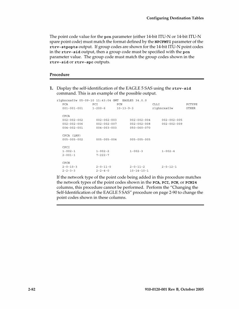
2-82 910-0120-001 Rev B, October 2005
Configuring Destination Tables
The point code value for the pcn parameter (either 14-bit ITU-N or 14-bit ITU-N spare point code) must match the format defined by the NPCFMTI parameter of the rtrv-stpopts output. If group codes are shown for the 14-bit ITU-N point codes in the rtrv-sid output, then a group code must be specified with the pcn parameter value. The group code must match the group codes shown in the rtrv-sid or rtrv-spc outputs.
Procedure
1. Display the self-identification of the EAGLE 5 SAS using the rtrv-sid command. This is an example of the possible output.
rlghncxa03w 05-09-10 11:43:04 GMT EAGLE5 34.0.0 PCA PCI PCN CLLI PCTYPE 001-001-001 1-200-6 10-13-9-3 rlghncxa03w OTHER
CPCA 002-002-002 002-002-003 002-002-004 002-002-005 002-002-006 002-002-007 002-002-008 002-002-009 004-002-001 004-003-003 050-060-070
CPCA (LNP) 005-005-002 005-005-004 005-005-005
CPCI 1-002-1 1-002-2 1-002-3 1-002-4 2-001-1 7-222-7
CPCN 2-0-10-3 2-0-11-0 2-0-11-2 2-0-12-1 2-2-3-3 2-2-4-0 10-14-10-1
If the network type of the point code being added in this procedure matches the network types of the point codes shown in the PCA, PCI, PCN, or PCN24 columns, this procedure cannot be performed. Perform the “Changing the Self-Identification of the EAGLE 5 SAS” procedure on page 2-90 to change the point codes shown in these columns.

Configuring Destination Tables
910-0120-001 Rev B, October 2005 2-83
NOTE: If an ITU-I or 14-bit ITU-N spare point code is displayed in the rtrv-sid output in step 1, or if an ITU-I or 14-bit ITU-N spare point code is not being added in this procedure, skip step 2 and go to step 3.
2. Verify whether or not the ITU National and International Spare Point Code Support feature is enabled by entering the rtrv-ctrl-feat command with the part number of this feature. Enter this command.
rtrv-ctrl-feat:partnum=893013601
This is an example of the possible output.
rlghncxa03w 05-09-28 21:15:37 GMT EAGLE5 34.0.0The following features have been permanently enabled:
Feature Name Partnum Status QuantitySpare Point Code Support 893013601 on ----
The following features have been temporarily enabled:
Feature Name Partnum Status Quantity Trial Period LeftZero entries found.
The following features have expired temporary keys:
Feature Name PartnumZero entries found.
If the ITU National and International Spare Point Code Support feature is not enabled, perform the “Activating the ITU National and International Spare Point Code Support Feature” procedure on page 2-42 to enable the ITU National and International Spare Point Code Support feature.
NOTE: If the pcn parameter is not being used in this procedure, skip this step and step 4, and go to step 5.
3. Display the existing values for the npcfmti parameter, by entering the rtrv-stpopts command. The value for the npcfmti parameter is shown in the NPCFMTI field. This is an example of the possible output.rlghncxa03w 05-09-17 16:02:05 GMT EAGLE5 34.0.0STP OPTIONS-----------------------NPCFMTI 4-4-4-2
NOTE: The rtrv-stpopts command output contains other fields that are not used by this procedure. If you wish to see all the fields displayed by the rtrv-stpopts command, see the rtrv-stpopts command description in the Commands Manual.
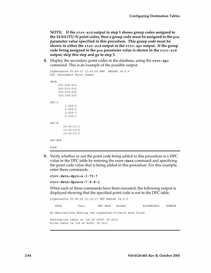
2-84 910-0120-001 Rev B, October 2005
Configuring Destination Tables
NOTE: If the rtrv-sid output in step 1 shows group codes assigned to the 14-bit ITU-N point codes, then a group code must be assigned to the pcn parameter value specified in this procedure. This group code must be shown in either the rtrv-sid output or the rtrv-spc output. If the group code being assigned to the pcn parameter value is shown in the rtrv-sid output, skip this step and go to step 5.
4. Display the secondary point codes in the database, using the rtrv-spc command. This is an example of the possible output.
rlghncxa03w 05-09-07 11:43:04 GMT EAGLE5 34.0.0SPC (Secondary Point Codes)
SPCA 001-010-010 002-010-010 003-010-010 010-100-010
SPC-I 1-253-5 2-254-6 3-255-7 4-100-1
SPC-N 10-01-11-1 13-02-12-0 14-15-12-1
SPC-N24
none
5. Verify whether or not the point code being added in this procedure is a DPC value in the DPC table by entering the rtrv-dstn command and specifying the point code value that is being added in this procedure. For this example, enter these commands.
rtrv-dstn:dpci=s-3-75-7
rtrv-dstn:dpcn=s-7-9-8-1
When each of these commands have been executed, the following output is displayed showing that the specified point code is not in the DPC table.
rlghncxa03w 05-09-28 21:16:37 GMT EAGLE5 34.0.0
DPCA CLLI BEI ELEI ALIASI ALIASN/N24 DOMAIN
No destinations meeting the requested criteria were found
Destination table is (22 of 2000) 1% fullAlias table is (18 of 8000) 1% full

Configuring Destination Tables
910-0120-001 Rev B, October 2005 2-85
6. Verify whether or not the point code being added in this procedure is an alias point code in the DPC table by entering the rtrv-dstn command and specifying the point code value that is being added in this procedure. For this example, enter these commands.
rtrv-dstn:aliasi=s-3-75-7
rtrv-dstn:aliasn=s-7-9-8-1
When each of these commands have been executed, the following output is displayed showing that the specified point code is not an alias point code in the DPC table.
rlghncxa03w 05-09-28 21:16:37 GMT EAGLE5 34.0.0
DPCA CLLI BEI ELEI ALIASI ALIASN/N24 DOMAIN
No destinations meeting the requested criteria were found
Destination table is (22 of 2000) 1% fullAlias table is (18 of 8000) 1% full
If the point code specified in steps 5 and 6 is shown in the DPC table, choose another point code to add to the self-identification and repeat steps 5 and 6.
If the point code specified in steps 5 and 6 is not shown in the DPC table, go to step 7.
7. Add the point code to the self-identification of the EAGLE 5 SAS using the ent-sid command with the pca, pci, pcn, or pcn24 parameters and according to these rules.
• If the pcn parameter is specified with the ent-sid command, the pcn24 parameter cannot be specified.
• If the pcn24 parameter is specified with the ent-sid command, the pcn parameter cannot be specified.
• For pcn parameter values, the format of the point code must match the format defined by the NPCFMTI parameter of the rtrv-stpopts output. If group codes are shown in the rtrv-sid output in step 1, a group code must be assigned to the pcn parameter value being added in this procedure. This group code must be shown either in the rtrv-sid or rtrv-spc output.
• The point code values must be full point codes.
• The ITU National and International Spare Point Code Support feature must be enabled to specify an ITU-I or 14-bit ITU-N spare point code.
• The point code specified in this procedure cannot be defined as a capability point code.
• See the “ANSI Point Codes” section on page 2-4 for information about entering ANSI point codes.

2-86 910-0120-001 Rev B, October 2005
Configuring Destination Tables
For this example, enter this command.
ent-sid:pci=s-3-75-7:pcn=s-7-9-8-1
When this command has successfully completed, this message should appear.
rlghncxa03w 05-09-07 09:17:40 GMT EAGLE5 34.0.0ENT-SID: MASP A - COMPLTD
8. Verify the changes using the rtrv-sid command. This is an example of the possible output.
rlghncxa03w 05-09-10 11:43:04 GMT EAGLE5 34.0.0 PCA PCI PCN CLLI PCTYPE 001-001-001 1-200-6 10-13-9-3 rlghncxa03w OTHER s-3-75-7 s-7-9-8-1
CPCA 002-002-002 002-002-003 002-002-004 002-002-005 002-002-006 002-002-007 002-002-008 002-002-009 004-002-001 004-003-003 050-060-070
CPCA (LNP) 005-005-002 005-005-004 005-005-005 006-006-006
CPCI 1-002-1 1-002-2 1-002-3 1-002-4 2-001-1 7-222-7
CPCN 2-0-10-3 2-0-11-0 2-0-11-2 2-0-12-1 2-2-3-3 2-2-4-0 10-14-10-1
9. Back up the new changes, using the chg-db:action=backup:dest=fixed command. These messages should appear; the active Maintenance and Administration Subsystem Processor (MASP) appears first.
BACKUP (FIXED) : MASP A - Backup starts on active MASP.BACKUP (FIXED) : MASP A - Backup on active MASP to fixed disk complete.BACKUP (FIXED) : MASP A - Backup starts on standby MASP.BACKUP (FIXED) : MASP A - Backup on standby MASP to fixed disk complete.
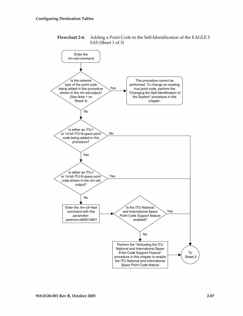
Configuring Destination Tables
910-0120-001 Rev B, October 2005 2-87
Flowchart 2-6. Adding a Point Code to the Self-Identification of the EAGLE 5 SAS (Sheet 1 of 3)
Enter thertrv-sid command
Is the networktype of the point code
being added in this procedureshown in the rtrv-sid output?
(See Note 1 onSheet 3)
Yes
To Sheet 2
Is either an ITU-Ior 14-bit ITU-N spare pointcode being added in this
procedure?
Perform the "Activating the ITUNational and International Spare
Point Code Support Feature"procedure in this chapter to enablethe ITU National and International
Spare Point Code feature
No
No
Yes
This procedure cannot beperformed. To change an existing
true point code, perform the"Changing the Self-Identification of
the System" procedure in thischapter.
Enter the rtrv-ctrl-featcommand with this
parameter::partnum=893013601
Is either an ITU-Ior 14-bit ITU-N spare pointcode shown in the rtrv-sid
output?
No
Yes
Is the ITU Nationaland International Spare
Point Code Support featureenabled?
Yes
No

2-88 910-0120-001 Rev B, October 2005
Configuring Destination Tables
Flowchart 2-6. Adding a Point Code to the Self-Identification of the EAGLE 5 SAS (Sheet 2 of 3)
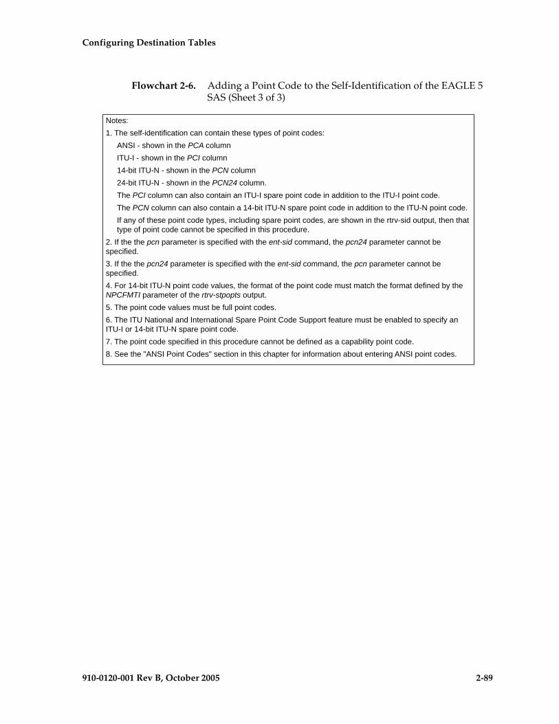
Configuring Destination Tables
910-0120-001 Rev B, October 2005 2-89
Flowchart 2-6. Adding a Point Code to the Self-Identification of the EAGLE 5 SAS (Sheet 3 of 3)

2-90 910-0120-001 Rev B, October 2005
Configuring Destination Tables
Changing the Self-Identification of the EAGLE 5 SAS
This procedure is used to change the self-identification of the EAGLE 5 SAS using the chg-sid command. The self-identification of the EAGLE 5 SAS is a set of point codes made up of a true point code (PC) and a capability point code (CPC) for each network type to which the EAGLE 5 SAS is connected. A capability point code identifies a group of nodes that have similar capabilities, for example, global title translation.
CAUTION: Use this procedure only during periods of low traffic. If the EAGLE 5 SAS’s point code, defined by the pc/pca/pci/pcn/pcn24 parameter, is changed with the procedure, the EAGLE 5 SAS must be reinitialized with the init-sys command. The init-sys command reboots the entire EAGLE 5 SAS and reloads all cards with the updated self-identification information. The chg-stpopts command rstrdev parameter can be used to turn on the Persistent Device States (PDS) feature. If PDS is on, the current device states for cards, signaling links, and terminals are restored after the init-sys command has executed. Refer to the chg-stpopts command description in the Commands Manual for more information about PDS.
NOTE: If PCA, PCI, or PCN fields in the rtrv-sid output do not contain any values, and you only wish to add these values, it is recommended that the “Adding a Point Code to the Self-Identification of the EAGLE 5 SAS” procedure on page 2-81 be used to add these values instead of using this procedure as the “Adding a Point Code to the Self-Identification of the EAGLE 5 SAS” procedure does not require the EAGLE 5 SAS to be re-initialized after the point code value is added.
The chg-sid command uses these parameters:
:pc/pca/pci/pcn/pcn24 – The point code used to uniquely identify the EAGLE 5 SAS or, with the value none, the point code is defined by the pc/pca/pcn24 parameter is removed from the database. Removing the pci or pcn value should be done by using the npci or npcn parameters.
:cpc/cpca/cpci/cpcn/cpcn24 – The point code used to identify a group of functionally related nodes in the signaling network to which the EAGLE 5 SAS belongs. This point code is called the capability point code.
:ncpc/ncpca/ncpci/ncpcn/ncpcn24 – The new capability point code that replaces an existing capability point code in the database or, with the value none, removes an existing capability point code from the database.
:npci/npcn – The new ITU-I (npci) or 14-bit ITU-N (npcn) point code used to uniquely identify the EAGLE 5 SAS that replaces an existing pci or pcn parameter value, with the value none, removes an existing pci or pcn parameter value from the database. The npci/npcn parameter values cannot be equal to any cpc or pc parameter values. The pci parameter must be specified if the npci parameter is specified. The pcn parameter must be specified if the npcn parameter is specified. The new ITU-I or 14-bit ITU-N

Configuring Destination Tables
910-0120-001 Rev B, October 2005 2-91
point code values (npci/npcn) must be the same type as the pci/pcn parameter value. For example, if the pci value is a non-spare point code, the npci value must be a non-spare point code. If the pci value is a spare point code, the npci value must be a spare point code.
NOTE: See “Point Code Formats” on page 2-4 for a definition of the point code types that are used on the EAGLE 5 SAS and for a definition of the different formats that can be used for ITU national point codes.
:clli – The Common Language Location Identifier assigned to the EAGLE 5 SAS
:pctype – Point code type
:cpctype – the type of capability point code, STP, LNP, INP, or EIR
The self-identification of the EAGLE 5 SAS can consist of an ANSI point code, an ITU international non-spare point code, an ITU international spare point code, a 14-bit ITU national non-spare point code, a 14-bit ITU national spare point code, or a 24-bit ITU national point code, or combinations of these types of point codes. The self-identification of the EAGLE 5 SAS cannot have both a 14-bit ITU-N point code (spare or non-spare) and a 24-bit ITU-N point code.
The self-identification of the EAGLE 5 SAS must contain point codes whose formats match the network the EAGLE 5 SAS is connected to. For example, if the EAGLE 5 SAS is connected to an ANSI network, the self-identification of the EAGLE 5 SAS must contain an ANSI point code. If the EAGLE 5 SAS is connected to an ITU international network, the self-identification of the EAGLE 5 SAS must contain an ITU international point code. If the EAGLE 5 SAS is connected to an ITU national network, the self-identification of the EAGLE 5 SAS must contain either a 14-bit or a 24-bit ITU national point code.
The self-identification of the EAGLE 5 SAS can contain capability point codes. A capability point code is used by the SS7 protocol to identify a group of functionally related nodes in the signaling network. The self-identification of the EAGLE 5 SAS can contain up to 96 capability point codes which can be all one point code network type, or a mixture of all three point code network types.
The EAGLE 5 SAS can contain an ANSI capability point code, an ITU national capability point code (spare or non-spare), and either a 14-bit (spare or non-spare) or a 24-bit ITU-N capability point code.
NOTE: The self-identification of the EAGLE 5 SAS cannot contain private point codes, and private point codes cannot be assigned as capability point codes.
ITU international and 14-bit ITU national spare point codes can be specified only if the ITU National and International Spare Point Code Support feature is enabled. The status of this feature can be verified by entering the rtrv-ctrl-feat command. If the ITU National and International Spare Point Code Support feature is not enabled, perform the “Activating the ITU National and International Spare Point Code Support Feature” procedure on page 2-42 to enable the ITU National and International Spare Point Code Support feature.

2-92 910-0120-001 Rev B, October 2005
Configuring Destination Tables
The self-identification of the EAGLE 5 SAS can also contain a CLLI, the common language location identifier of the EAGLE 5 SAS.
The CLLI of the EAGLE 5 SAS cannot match the CLLI of any destination point code. Use the rtrv-dstn command to verify the CLLIs of the destination point codes in the database.
If the CLLI of the EAGLE 5 SAS is changed, and the SEAS feature is on, the OAP configuration must be updated with the new CLLI. Go to the System Manual - EOAP to update the OAP configuration.
If the CLLI of the EAGLE 5 SAS is to be changed, and the Eagle Support for Integrated Sentinel (E5IS) feature is on, the EISCOPY option must be off before the chg-sid command is executed. The value of the EISCOPY option can be verified with the rtrv-eisopts command. After the chg-sid command is executed, the EISCOPY option must be changed back to on.
The LNP capability point code, specified with the cpctype=lnp parameter, can be only an ANSI point code, specified with either the cpc, cpca, ncpc, or ncpca parameters.
The INP capability point code, specified with the cpctype=inp parameter, and the EIR capability point code, specified with the cpctype=eir parameter, can be either an ITU-I, 14-bit ITU-N, or 24-bit ITU-N point code, specified with either the cpci, cpcn, cpcn24, ncpci, ncpcn, or ncpcn24 parameters.
The STP capability point code, specified with the cpctype=stp parameter, can be any point code type.
The LNP feature must be enabled to specify the cpctype=lnp parameter. This can be verified with the rtrv-ctrl-feat command. If the LNP feature is enabled, the entry LNP TNs is shown in the rtrv-ctrl-feat command output with a quantity greater than zero. If the LNP feature is not enabled, perform the procedures in the LNP Feature Activation Guide to enable the LNP feature.
The pctype parameter of the chg-sid command determines the format of point codes (but not the ITU international or ITU national point codes) that can be used on the EAGLE 5 SAS, ansi and other. The value ansi means the EAGLE 5 SAS supports point codes that meet the ANSI standard. The value other means that the EAGLE 5 SAS supports point codes that do not meet the ANSI standard. This does not apply to ITU international or ITU national point codes.
This procedure causes a change in the routing information for this node. Make sure that all other nodes that route messages to this node are notified of these changes.
The point code of the EAGLE 5 SAS cannot match the capability point codes of the EAGLE 5 SAS. The point code of the EAGLE 5 SAS and the capability point codes of the EAGLE 5 SAS are shown in step 1.
The point code and capability point codes of the EAGLE 5 SAS cannot match any destination point codes. Use the rtrv-dstn command to display the destination point codes in the database.

Configuring Destination Tables
910-0120-001 Rev B, October 2005 2-93
The point code and capability point codes of the EAGLE 5 SAS cannot be defined as a destination point code of a route. Use the rtrv-rte command to display the destination point codes of the routes in the database.
The point code of the EAGLE 5 SAS or the capability point codes, specified by the pc/pca/pci/pcn/pcn24, cpc/cpca/cpci/cpcn/cpcn24 or ncpc/ncpca/ncpci/ncpcn/ncpcn24 parameters, must be a full point code and cannot be a cluster point code. The point code containing all zeros cannot be used as a value for these parameters.
If either the cpctype parameter or the capability point code parameter (cpc/cpca/cpci/cpcn/cpcn24) are specified, the other parameter must be specified.
INP capability point codes, specified with the cpctype=inp parameter, can only be specified if the INP feature is turned on. Enter the rtrv-feat command to verify whether or not the INP feature is on. If the INP feature is off, go to the Feature Manual - INP to turn the INP feature on.
EIR capability point codes, specified with the cpctype=eir parameter, can only be specified if the EIR feature is enabled and activated. Enter the rtrv-ctrl-feat command to verify whether or not the EIR feature is enabled and activated. If the EIR feature is not enabled or activated, go to the Feature Manual - EIR to enable and activate the EIR feature.
If the new capability point code parameter (ncpc/ncpca/ncpci/ncpcn/ncpcn24) is specified, the capability point code parameter (cpc/cpca/cpci/cpcn/cpcn24) and the cpctype parameters must be specified.
Only one of the new capability point code parameters (ncpc/ncpca/ncpci/ncpcn/npcn24) can be specified with the chg-sid command.
The new capability point code (ncpc/ncpca/ncpci/ncpcn/npcn24) must be of the same point code type as the capability point code (cpc/cpca/cpci/cpcn/cpcn24) specified in the command. For example, if an ITU international capability point code (cpci) is being replaced, then only the ncpci parameter can be specified.
The point code of the EAGLE 5 SAS cannot be changed if it is referenced in the mated application table. Enter the rtrv-map command to verify if the EAGLE 5 SAS’s point code is being referenced in the mated application table. The EAGLE 5 SAS’s point code would be shown in the PCA, PCI, PCN, PCN24, MPCA, MPCI, MPCN, or MPCN24 fields of the rtrv-map command output. If the EAGLE 5 SAS’s point code is referenced by the mated application table, go to the “Removing a Mated Application” procedure in the Database Administration Manual - Global Title Translation, and remove the mated applications that reference the EAGLE 5 SAS’s point code.

2-94 910-0120-001 Rev B, October 2005
Configuring Destination Tables
The destination point codes and alias point codes are shown in the DPCA, DPCI, DPCN, DPCN24, ALIASA, ALIASI, ALIASN, and ALIASN24 fields in the rtrv-dstn command output. The EAGLE 5 SAS’s point code and capability point codes are displayed in the PCA, PCI, PCN, PCN24, CPCA, CPCI, CPCN, and CPCN24 fields in the rtrv-sid command output.
To assign group codes to a 14-bit ITU-N point code, the ITU duplicate point code and multiple point code support features must be on. If the ITU National Duplicate Point Code feature is on, the entry ITUDUPPC = on is shown in the rtrv-feat command output. If the multiple point code support feature is on, the entry MPC = on is shown in the rtrv-feat command output. For more information on using group codes with 14-bit ITU-N point codes, see the “ITU National Duplicate Point Codes” section on page 2-16.
NOTE: Once the ITU duplicate point code and multiple point code support features are turned on with the chg-feat command, they cannot be turned off.
The ITU duplicate point code and multiple point code support features must be purchased before you turn this feature on with the chg-feat command. If you are not sure if you have purchased the ITU duplicate point code and multiple point code support features, contact your Tekelec Sales Representative or Account Representative.
If you wish to specify the pcn24 parameter with the chg-sid command and the rtrv-sid output shows the PCN field, the 14-bit ITU-N point code value, shown in the PCN field must be removed with the npcn=none parameter before the pcn24 parameter value can be specified by the chg-sid command. If the PCN field contains both spare and non-spare point code values, both the spare and non-spare 14-bit ITU-N point code values must be removed before the pcn24 parameter can be specified. If no value is shown in the PCN field, specifying the npcn=none parameter is not necessary.
If you wish to specify the pcn parameter with the chg-sid command and the rtrv-sid output shows the PCN24 field, the 24-bit ITU-N point code value, shown in the PCN24 field must be removed with the pcn24=none parameter before the pcn parameter value can be specified by the chg-sid command. If no value is shown in the PCN24 field, specifying the pcn24=none parameter is not necessary.
When the EAGLE 5 SAS is initially installed, the self-identification of the EAGLE 5 SAS must be configured before any destination point codes can be configured in the database.
Configuring Destination Tables
910-0120-001 Rev B, October 2005 2-95
For the examples in this procedure, the self-identification of the EAGLE 5 SAS is being changed to these values:
ANSI point code = 100-100-100
ITU international point code = 3-75-7
14-bit ITU national point code = 7-9-8-1
LNP capability point code = 006-006-006
The format of the 14-bit ITU national point codes used in these examples is 4-4-4-2.
Canceling the RTRV-DSTN, RTRV-MAP, and RTRV-RTE Commands
Because the rtrv-dstn, rtrv-map, and rtrv-rte commands used in this procedure can output information for a long period of time, the rtrv-dstn, rtrv-map, and rtrv-rte commands can be canceled and the output to the terminal stopped. There are three ways that the rtrv-dstn, rtrv-map, and rtrv-rte commands can be canceled:
• Press the F9 function key on the keyboard at the terminal where the rtrv-dstn, rtrv-map, or rtrv-rte command was entered.
• Enter the canc-cmd without the trm parameter at the terminal where the rtrv-dstn, rtrv-map, or rtrv-rte command was entered.
• Enter the canc-cmd:trm=<xx>, where <xx> is the terminal where the rtrv-dstn, rtrv-map, or rtrv-rte command was entered, from another terminal other than the terminal where the rtrv-dstn, rtrv-map, and rtrv-rte commands were entered. To enter the canc-cmd:trm=<xx> command, the terminal must allow Security Administration commands to be entered from it and the user must be allowed to enter Security Administration commands. The terminal’s permissions can be verified with the rtrv-secu-trm command. The user’s permissions can be verified with the rtrv-user or rtrv-secu-user commands.
For more information about the canc-cmd command, refer to the Commands Manual.
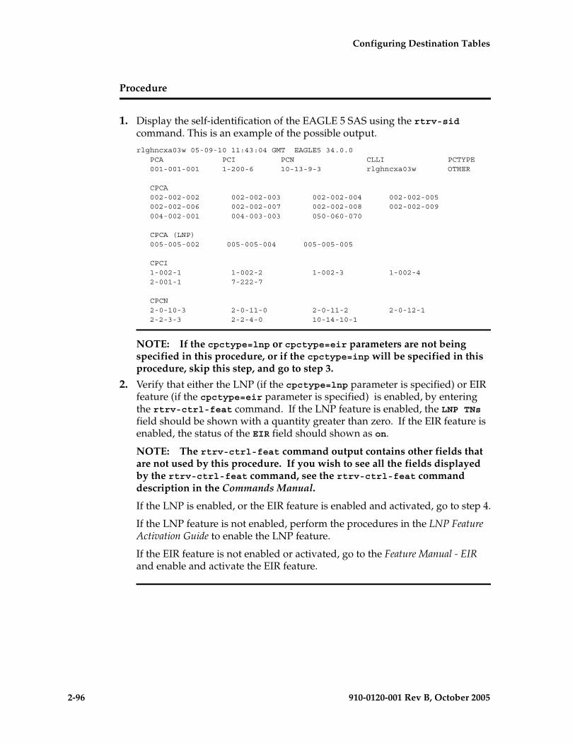
2-96 910-0120-001 Rev B, October 2005
Configuring Destination Tables
Procedure
1. Display the self-identification of the EAGLE 5 SAS using the rtrv-sid command. This is an example of the possible output.
rlghncxa03w 05-09-10 11:43:04 GMT EAGLE5 34.0.0 PCA PCI PCN CLLI PCTYPE 001-001-001 1-200-6 10-13-9-3 rlghncxa03w OTHER
CPCA 002-002-002 002-002-003 002-002-004 002-002-005 002-002-006 002-002-007 002-002-008 002-002-009 004-002-001 004-003-003 050-060-070
CPCA (LNP) 005-005-002 005-005-004 005-005-005
CPCI 1-002-1 1-002-2 1-002-3 1-002-4 2-001-1 7-222-7
CPCN 2-0-10-3 2-0-11-0 2-0-11-2 2-0-12-1 2-2-3-3 2-2-4-0 10-14-10-1
NOTE: If the cpctype=lnp or cpctype=eir parameters are not being specified in this procedure, or if the cpctype=inp will be specified in this procedure, skip this step, and go to step 3.
2. Verify that either the LNP (if the cpctype=lnp parameter is specified) or EIR feature (if the cpctype=eir parameter is specified) is enabled, by entering the rtrv-ctrl-feat command. If the LNP feature is enabled, the LNP TNs field should be shown with a quantity greater than zero. If the EIR feature is enabled, the status of the EIR field should shown as on.
NOTE: The rtrv-ctrl-feat command output contains other fields that are not used by this procedure. If you wish to see all the fields displayed by the rtrv-ctrl-feat command, see the rtrv-ctrl-feat command description in the Commands Manual.
If the LNP is enabled, or the EIR feature is enabled and activated, go to step 4.
If the LNP feature is not enabled, perform the procedures in the LNP Feature Activation Guide to enable the LNP feature.
If the EIR feature is not enabled or activated, go to the Feature Manual - EIR and enable and activate the EIR feature.
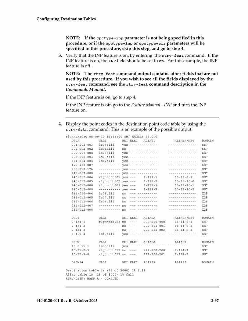
Configuring Destination Tables
910-0120-001 Rev B, October 2005 2-97
NOTE: If the cpctype=inp parameter is not being specified in this procedure, or if the cpctype=lnp or cpctype=eir parameters will be specified in this procedure, skip this step, and go to step 4.
3. Verify that the INP feature is on, by entering the rtrv-feat command. If the INP feature is on, the INP field should be set to on. For this example, the INP feature is off.
NOTE: The rtrv-feat command output contains other fields that are not used by this procedure. If you wish to see all the fields displayed by the rtrv-feat command, see the rtrv-feat command description in the Commands Manual.
If the INP feature is on, go to step 4.
If the INP feature is off, go to the Feature Manual - INP and turn the INP feature on.
4. Display the point codes in the destination point code table by using the rtrv-dstn command. This is an example of the possible output.
rlghncxa03w 05-09-10 11:43:04 GMT EAGLE5 34.0.0 DPCA CLLI BEI ELEI ALIASI ALIASN/N24 DOMAIN 001-002-003 ls04clli yes --- ---------- -------------- SS7 002-002-002 ls01clli no --- ---------- -------------- SS7 002-007-008 ls06clli yes --- ---------- -------------- SS7 003-003-003 ls03clli yes --- ---------- -------------- SS7 004-004-004 ls02clli yes --- ---------- -------------- SS7 179-100-087 ----------- yes --- ---------- -------------- SS7 200-050-176 ----------- yes --- ---------- -------------- SS7 240-007-000 ----------- yes --- ---------- -------------- SS7 240-012-004 rlghncbb001 yes --- 1-111-1 10-13-9-3 SS7 240-012-005 rlghncbb002 yes --- 1-112-2 10-13-10-0 SS7 240-012-006 rlghncbb003 yes --- 1-112-3 10-13-10-1 SS7 240-012-008 ----------- yes --- 1-113-5 10-13-10-2 SS7 244-010-004 ls06clli no --- ---------- -------------- X25 244-012-005 ls07clli no --- ---------- -------------- X25 244-012-006 ls08clli no --- ---------- -------------- X25 244-012-007 ----------- no --- ---------- -------------- X25 244-012-008 ----------- no --- ---------- -------------- X25
DPCI CLLI BEI ELEI ALIASA ALIASN/N24 DOMAIN 2-131-1 rlghncbb023 no --- 222-210-000 11-11-8-1 SS7 2-131-2 ----------- no --- 222-211-001 11-11-8-2 SS7 2-131-3 ----------- no --- 222-211-002 11-11-8-3 SS7 3-150-4 lsi7clli yes --- -------------- -------------- SS7
DPCN CLLI BEI ELEI ALIASA ALIASI DOMAIN 10-6-15-1 lsn5clli yes --- -------------- ---------- SS7 10-15-2-3 rlghncbb013 no --- 222-200-200 2-121-1 SS7 10-15-3-0 rlghncbb013 no --- 222-200-201 2-121-2 SS7
DPCN24 CLLI BEI ELEI ALIASA ALIASI DOMAIN
Destination table is (24 of 2000) 1% fullAlias table is (18 of 8000) 1% fullRTRV-DSTN: MASP A - COMPLTD

2-98 910-0120-001 Rev B, October 2005
Configuring Destination Tables
5. Display the current route configuration, using the rtrv-rte command. This is an example of the possible output.
rlghncxa03w 05-09-07 11:43:04 GMT EAGLE5 34.0.0 DPCA ALIASI ALIASN/N24 LSN RC APCA 140-012-004 1-111-1 10-13-12-1 ls000001 10 240-012-002 ls000002 10 240-012-002 ls000003 20 240-012-002 ls000004 30 240-012-002 ls000005 40 240-012-002 ls000006 50 240-012-002 CLLI=dp1 140-012-005 1-111-2 10-13-12-2 ls000001 10 240-012-002 ls000002 10 240-012-002 ls000003 20 240-012-002 ls000004 30 240-012-002 ls000005 40 240-012-002 ls000006 50 240-012-002 CLLI=dp2
DPCI ALIASN/N24 ALIASA LSN RC APC 2-234-5 11-13-3-3 240-111-111 ls100001 10 1-234-5 ls100002 10 1-234-6 ls100003 20 1-234-7 ls100004 30 1-234-1 ls100005 40 1-234-2 ls100006 50 1-234-3 CLLI=idp1
DPCN ALIASA ALIASI LSN RC APC 12-12-13-3 011-222-111 0-001-1 ls200001 10 10-13-9-3 ls200002 10 10-13-10-0 ls200003 20 10-13-10-1 ls200004 30 10-13-10-2 ls200005 40 10-13-10-3 ls200006 50 10-13-11-0 CLLI=ndp1
DPCN24 ALIASA ALIASI LSN RC APC
NOTE: If the pcn, npcn, cpcn, or ncpcn parameters are not being used in this procedure, skip this step and go to step 9.
6. Display the existing values for the npcfmti parameter, by entering the rtrv-stpopts command. The value for the npcfmti parameter is shown in the NPCFMTI field. This is an example of the possible output.rlghncxa03w 05-09-17 16:02:05 GMT EAGLE5 34.0.0STP OPTIONS-----------------------NPCFMTI 4-4-4-2
NOTE: The rtrv-stpopts command output contains other fields that are not used by this procedure. If you wish to see all the fields displayed by the rtrv-stpopts command, see the rtrv-stpopts command description in the Commands Manual.

Configuring Destination Tables
910-0120-001 Rev B, October 2005 2-99
If you wish to change the format of the 14-bit ITU national point codes, go to the “14-Bit ITU National Point Code Formats” section on page 2-10. Changing the formats of the 14-bit ITU national point codes will change how any existing 14-bit ITU national point codes are displayed in the database.
NOTE: If group codes are not assigned to the 14-bit ITU national point codes in the EAGLE 5 SAS, or if the 14-bit ITU national point codes have group codes assigned to them, skip this step and go to step 8.
7. Enter the rtrv-feat command, or examine the rtrv-feat output in step 3, if step 3 was performed, to verify that the Multiple Point Code Support and ITU Duplicate Point Code Support features are on. If the Multiple Point Code Support feature is on, the MPC field should be set to on. If the ITU Duplicate Point Code Support feature is on, the ITUDUPPC field should be set to on. For this example, these features are off.
NOTE: The rtrv-feat command output contains other fields that are not used by this procedure. If you wish to see all the fields displayed by the rtrv-feat command, see the rtrv-feat command description in the Commands Manual.
If the ITU Duplicate Point Code Support feature is off and the Multiple Point Code feature is on, enter this command.
chg-feat:ituduppc=on
If both features are off, enter this command.
chg-feat:mpc=on:ituduppc=on
NOTE: Once the ITU Duplicate Point Code and Multiple Point Code features are turned on with the chg-feat command, they cannot be turned off.
The ITU Duplicate Point Code and Multiple Point Code features must be purchased before you turn these features on with the chg-feat command. If you are not sure if you have purchased these features, contact your Tekelec Sales Representative or Account Representative.
When the chg-feat has successfully completed, this message should appear.
rlghncxa03w 05-09-07 00:57:31 GMT EAGLE5 34.0.0CHG-FEAT: MASP A - COMPLTD

2-100 910-0120-001 Rev B, October 2005
Configuring Destination Tables
NOTE: If an ITU-I or 14-bit ITU-N spare point code is displayed in the rtrv-sid output in step 1, or if an ITU-I or 14-bit ITU-N spare point code is not being specified in this procedure, skip step 8 and go to step 9.
8. If spare point codes are being specified in this procedure, the ITU National and International Spare Point Code Support feature must be enabled. The rtrv-ctrl-feat command shows the status of the ITU National and International Spare Point Code Support feature. If step 2 was performed in this procedure, verify that the ITU National and International Spare Point Code Support feature is enabled.
If step 2 was not performed in this procedure, enter the rtrv-ctrl-feat command with the part number of this feature. Enter this command.
rtrv-ctrl-feat:partnum=893013601
This is an example of the possible output.
rlghncxa03w 05-09-28 21:15:37 GMT EAGLE5 34.0.0The following features have been permanently enabled:
Feature Name Partnum Status QuantitySpare Point Code Support 893013601 on ----
The following features have been temporarily enabled:
Feature Name Partnum Status Quantity Trial Period LeftZero entries found.
The following features have expired temporary keys:
Feature Name PartnumZero entries found.
If the ITU National and International Spare Point Code Support feature is not enabled, perform the “Activating the ITU National and International Spare Point Code Support Feature” procedure on page 2-42 to enable the ITU National and International Spare Point Code Support feature.

Configuring Destination Tables
910-0120-001 Rev B, October 2005 2-101
NOTE: If the EAGLE 5 SAS’s point code is not being changed in this procedure, skip this step and step 10, and go to step 11.
9. Display the mated applications in the database, using the rtrv-map command. This is an example of the possible output.
rlghncxa03w 05-09-07 00:34:31 GMT EAGLE5 34.0.0MAP TABLE IS 2 % FULL (20 of 1024)
PCA SSN RC MULT MPCA MSSN MATERC MULT SRM MRC GRP NAME SSO255-001-000 250 10 SOL YES YES GRP01 ON255-001-000 251 10 SHR 253-001-002 254 10 SHR YES YES GRP01 OFF255-001-000 252 10 SOL YES YES GRP01 ON255-001-000 253 10 SHR 253-001-004 254 10 SHR YES YES GRP01 OFF255-001-001 255 10 DOM 253-001-005 254 20 DOM YES YES GRP01 ON255-001-001 250 10 DOM 253-001-001 254 20 DOM YES YES GRP01 OFF255-001-002 251 10 SHR 255-001-002 254 10 SHR NO YES GRP01 OFF255-001-002 252 10 DOM 255-001-003 254 20 DOM YES YES GRP01 ON255-001-002 253 10 SHR 255-001-004 254 10 SHR YES NO GRP01 ON
MAP TABLE IS 2 % FULL (20 of 1024)
PCI SSN RC MULT MPCI MSSN MATERC MULT SRM MRC GRP NAME SSO2-001-2 255 10 DOM 2-001-1 254 20 DOM --- --- GRP03 OFF
MAP TABLE IS 2 % FULL (20 of 1024)
PCN SSN RC MULT MPCN MSSN MATERC MULT SRM MRC GRP NAME SSO0-5-6-3 253 10 SHR 1-5-10-3 254 10 SHR --- --- GRP05 OFF
If the EAGLE 5 SAS’s point code is shown in the rtrv-map command output (in the PCA, PCI, PCN, PCN24, MPCA, MPCI, MCPN, or MPCN24 fields), go to the “Removing a Mated Application” procedure in the Database Administration Manual - Global Title Translation, and remove the EAGLE 5 SAS’s point code from the mated application table.
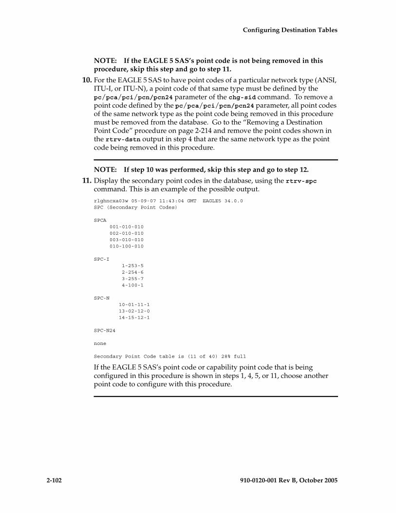
2-102 910-0120-001 Rev B, October 2005
Configuring Destination Tables
NOTE: If the EAGLE 5 SAS’s point code is not being removed in this procedure, skip this step and go to step 11.
10. For the EAGLE 5 SAS to have point codes of a particular network type (ANSI, ITU-I, or ITU-N), a point code of that same type must be defined by the pc/pca/pci/pcn/pcn24 parameter of the chg-sid command. To remove a point code defined by the pc/pca/pci/pcn/pcn24 parameter, all point codes of the same network type as the point code being removed in this procedure must be removed from the database. Go to the “Removing a Destination Point Code” procedure on page 2-214 and remove the point codes shown in the rtrv-dstn output in step 4 that are the same network type as the point code being removed in this procedure.
NOTE: If step 10 was performed, skip this step and go to step 12.
11. Display the secondary point codes in the database, using the rtrv-spc command. This is an example of the possible output.
rlghncxa03w 05-09-07 11:43:04 GMT EAGLE5 34.0.0SPC (Secondary Point Codes)
SPCA 001-010-010 002-010-010 003-010-010 010-100-010
SPC-I 1-253-5 2-254-6 3-255-7 4-100-1
SPC-N 10-01-11-1 13-02-12-0 14-15-12-1
SPC-N24
none
Secondary Point Code table is (11 of 40) 28% full
If the EAGLE 5 SAS’s point code or capability point code that is being configured in this procedure is shown in steps 1, 4, 5, or 11, choose another point code to configure with this procedure.

Configuring Destination Tables
910-0120-001 Rev B, October 2005 2-103
NOTE: If the clli parameter value is not being changed, skip steps 12 through 14, and go to step 15.
12. Enter the rtrv-feat command, or examine the rtrv-feat output in either steps 3, or 7, if steps 3, or 7 were performed, to verify that the Eagle Support for Integrated Sentinel feature is on. If the Eagle Support for Integrated Sentinel feature is on, the E5IS field should be set to on.
NOTE: The rtrv-feat command output contains other fields that are not used by this procedure. If you wish to see all the fields displayed by the rtrv-feat command, see the rtrv-feat command description in the Commands Manual.
NOTE: If the Eagle Support for Integrated Sentinel feature is not on, skip this step and step 14, and go to step 15.
13. Display the EISCOPY option by entering the rtrv-eisopts command. This is an example of the possible output.
rlghncxa03w 05-09-07 11:43:04 GMT EAGLE5 34.0.0EISOPTION STATUS--------------------------
EISCOPY ON
NOTE: If the EISCOPY option is off, skip this step and go to step 15.
CAUTION: Changing the EISCOPY option to off will disable the Eagle Support for Integrated Sentinel feature.
14. Turn the EISCOPY option off by entering the chg-eisopts command with the eiscopy=off parameter.
When the chg-eisopts has successfully completed, this message should appear.
rlghncxa03w 05-09-07 11:43:04 GMT EAGLE5 34.0.0CHG-EISOPTS: MASP A - COMPLTD
2-104 910-0120-001 Rev B, October 2005
Configuring Destination Tables
15. Change the value of the self-identification of the EAGLE 5 SAS, using the chg-sid command. For this example, the point code of the EAGLE 5 SAS is being changed to these values:
ANSI point code = 100-100-100
ITU international point code = 3-75-7
ITU national point code = 7-9-8-1
LNP capability point code = 006-006-006
To make these changes, enter this command.
chg-sid:pca=100-100-100:pci=3-75-7:pcn=7-9-8-1:cpca=006-006-006:cpctype=lnp
If you wish to specify the pcn24 parameter with the chg-sid command and the rtrv-sid output shows the PCN field, the 14-bit ITU-N point code value, shown in the PCN field must be removed with the npcn=none parameter before the pcn24 parameter value can be specified by the chg-sid command. If the PCN field contains both spare and non-spare point code values, both the spare and non-spare 14-bit ITU-N point code values must be removed before the pcn24 parameter can be specified. If no value is shown in the PCN field, specifying the npcn=none parameter is not necessary.
If you wish to specify the pcn parameter with the chg-sid command and the rtrv-sid output shows the PCN24 field, the 24-bit ITU-N point code value, shown in the PCN24 field must be removed with the pcn24=none parameter before the pcn parameter value can be specified by the chg-sid command. If no value is shown in the PCN24 field, specifying the pcn24=none parameter is not necessary.
If you wish to configure network routing point codes using the network indicator values 1 through 5, the pctype parameter value must be other. For more information on network routing point codes, see the “Network Routing” section on page 2-174.
When this command has successfully completed, this message should appear.
rlghncxa03w 05-09-07 09:17:40 GMT EAGLE5 34.0.0CHG-SID: MASP A - COMPLTD
If any of the pc/pca/pci/pcn/pcn24 parameters are changed, the EAGLE 5 SAS needs to be reinitialized. Go to step 17. A caution message is displayed indicating that the EAGLE 5 SAS needs to be reinitialized.
CAUTION: SYSTEM SITE ID HAS BEEN CHANGED, MANUAL RE-INITIALIZATION IS NEEDED
If the SEAS feature is on, shown by the entry SEAS = on in the rtrv-feat command output, and the clli parameter is changed, a caution message is displayed indicating that the OAPs must be configured with the new CLLI.
CAUTION: System CLLI has changed, OAP configuration is required
Go to the “Configuring the OAP from the EAGLE 5 SAS” section in the Database Administration Manual - System Management to update the OAP configuration.

Configuring Destination Tables
910-0120-001 Rev B, October 2005 2-105
NOTE: If the SEAS feature is not on, the OAPs are not present in the EAGLE 5 SAS, and the procedures in the System Manual - EOAP does not need to be performed.
If the point code of the EAGLE 5 SAS or capability point code is referenced by the gateway screening redirect function and the gateway screening redirect function is enabled, a caution message is displayed indicating that the gateway screening redirect function’s DPC must be changed to reference the new EAGLE 5 SAS’s point code. CAUTION: SYSTEM SITE ID WAS REFERENCED BY THE REDIRECT FUNCTION’S DPC
Use the chg-gws-redirect command to change the gateway screening redirect function’s DPC. Go to the “Changing the Gateway Screening Redirect Parameters” procedure in the Database Administration Manual - Features to change the gateway screening redirect function’s DPC.
NOTE: If the pc/pca/pci/pcn/pcn24 parameters were not changed in step 15, skip step this step and step 17, and go to step 18.CAUTION: The following init-sys command causes a complete EAGLE 5 SAS reload, and should only be used during periods of low traffic. Using this command ensures the updated self-identification information is loaded onto all cards, but will interrupt service.CAUTION: The chg-stpopts command rstrdev parameter can be used to turn on the Persistent Device States (PDS) feature. When PDS is turned off and the init-sys command executes, the EAGLE 5 SAS does not retain the manually initiated state (for example, OOS-MT-DSBLD) for the signaling links, cards, or terminals. After the command executes, the EAGLE 5 SAS attempts to bring all provisioned signaling links, cards, and terminals on-line, including those that were previously out of service. You will need to manually put each device back into its previous state after the EAGLE 5 SAS is back on-line. It is, therefore, advisable to print or electronically capture the output of the rept-stat-slk, rept-stat-card, and rept-stat-trm commands for reference prior to issuing the init-sys command. To restore a device to its previous state, issue the appropriate inhibit/deactivate command listed in the Commands Manual in the Related Commands section for each of the above rept-stat commands.When PDS is turned on using the chg-stpopts:rstrdev=on command, the EAGLE 5 SAS restores the previous device states of signaling links, terminals, and cards after the init-sys command has executed.
16. Enter the rtrv-stpopts command to display the setting of the rstrdev parameter.
Step 17 instructs you to enter the init-sys command.
If you do not want the EAGLE 5 SAS to restore previous device states after the init-sys command has executed and RSTRDEV is on in the rtrv-stpopts output, enter the chg-stpopts:rstrdev=off command.

2-106 910-0120-001 Rev B, October 2005
Configuring Destination Tables
If you want the EAGLE 5 SAS to restore previous device states after the init-sys command has executed, and RSTRDEV is off in the rtrv-stpopts output, enter the chg-stpopts:rstrdev=on command
Continue with step 17.
17. Reinitialize the EAGLE 5 SAS by entering the init-sys command.
NOTE: The init-sys command must be entered twice within 30 seconds for the EAGLE 5 SAS to be re-initialized. If the init-sys command is not executed twice within 30 seconds, the attempt to re-initialize the EAGLE 5 SAS is aborted.
When the init-sys command is first entered, this message should appear.rlghncxa03w 05-09-28 07:05:01 GMT EAGLE5 34.0.0CAUTION: This command causes a complete system reload, andwill result in traffic loss.Re-enter command within 30 seconds to confirm.
When the init-sys command is re-entered within the 30 second time limit, this message should appear.rlghncxa03w 05-09-28 07:05:17 GMT EAGLE5 34.0.0Init System command issued at terminal #3
From the time that the init-sys command is accepted, you must wait approximately two minutes before you can perform step 18 (logging onto the EAGLE 5 SAS). If the EAGLE 5 SAS terminal is in the VT-100/VT-320 mode, the terminal display will be refreshed with non-zero alarm counts. During this 2-minute interval, an intermediate screen refresh is caused by the MASPs role change from active to standby, and from standby to active. This screen refresh is typically a partial refresh, and the alarm indicators are set to zero.
If you are logged into the EAGLE 5 SAS in the KSR mode, the only response you will receive indicating that you are now able to log into the EAGLE 5 SAS is UAM 0009, MASP became active. UAM 0009 could be issued twice due to possible transient MASP role change (switching from active to standby).
Following the execution of the init-sys command, the MASP that was active before the init-sys command was entered will be the active MASP when the EAGLE 5 SAS has finished reinitializing.
18. Log into the EAGLE 5 SAS using the login command (or the act-user command).
This is an example of the messages that appear when the login session has successfully completed.
NOTICE: This is a private computer system. Unauthorized access or use may lead to prosecution.
0 LOGIN failures since last successful LOGINLast successful LOGIN was on port 4 on 04-06-02 @ 09:34:56
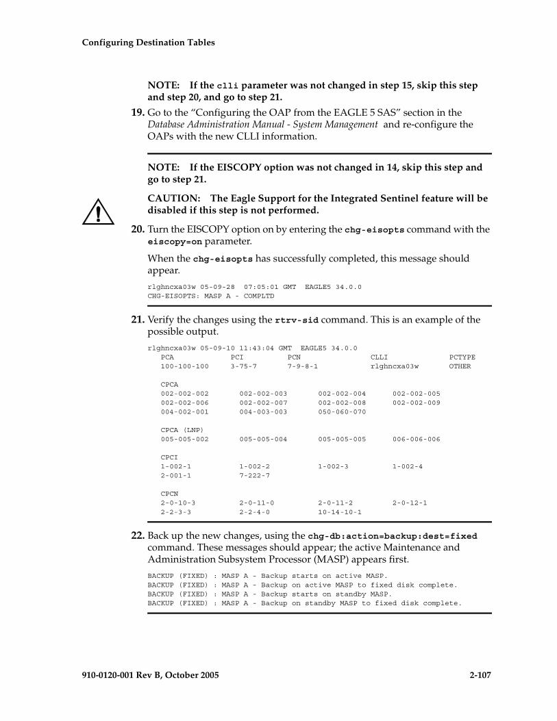
Configuring Destination Tables
910-0120-001 Rev B, October 2005 2-107
NOTE: If the clli parameter was not changed in step 15, skip this step and step 20, and go to step 21.
19. Go to the “Configuring the OAP from the EAGLE 5 SAS” section in the Database Administration Manual - System Management and re-configure the OAPs with the new CLLI information.
NOTE: If the EISCOPY option was not changed in 14, skip this step and go to step 21.
CAUTION: The Eagle Support for the Integrated Sentinel feature will be disabled if this step is not performed.
20. Turn the EISCOPY option on by entering the chg-eisopts command with the eiscopy=on parameter.
When the chg-eisopts has successfully completed, this message should appear.
rlghncxa03w 05-09-28 07:05:01 GMT EAGLE5 34.0.0CHG-EISOPTS: MASP A - COMPLTD
21. Verify the changes using the rtrv-sid command. This is an example of the possible output.
rlghncxa03w 05-09-10 11:43:04 GMT EAGLE5 34.0.0 PCA PCI PCN CLLI PCTYPE 100-100-100 3-75-7 7-9-8-1 rlghncxa03w OTHER
CPCA 002-002-002 002-002-003 002-002-004 002-002-005 002-002-006 002-002-007 002-002-008 002-002-009 004-002-001 004-003-003 050-060-070
CPCA (LNP) 005-005-002 005-005-004 005-005-005 006-006-006
CPCI 1-002-1 1-002-2 1-002-3 1-002-4 2-001-1 7-222-7
CPCN 2-0-10-3 2-0-11-0 2-0-11-2 2-0-12-1 2-2-3-3 2-2-4-0 10-14-10-1
22. Back up the new changes, using the chg-db:action=backup:dest=fixed command. These messages should appear; the active Maintenance and Administration Subsystem Processor (MASP) appears first.
BACKUP (FIXED) : MASP A - Backup starts on active MASP.BACKUP (FIXED) : MASP A - Backup on active MASP to fixed disk complete.BACKUP (FIXED) : MASP A - Backup starts on standby MASP.BACKUP (FIXED) : MASP A - Backup on standby MASP to fixed disk complete.

2-108 910-0120-001 Rev B, October 2005
Configuring Destination Tables
Flowchart 2-7. Changing the Self-Identification of the System (Sheet 1 of 11)
NOTE: Before executing this procedure, make sure you have purchased the ITU Duplicate Point Code and Multiple Point Code features. If you are not sure if you have purchased the ITU Duplicate Point Code and Multiple Point Code features, contact your Tekelec Sales Representative or Account Representative.

Configuring Destination Tables
910-0120-001 Rev B, October 2005 2-109
Flowchart 2-7. Changing the Self-Identification of the System (Sheet 2 of 11)
Are INP or EIR CPCs to be provisioned with
the chg-sid command?
Enter the rtrv-featcommand
INPCPCs
To Sheet 3
Is the INPfeature on?
Go to the FeatureManual - INP and
activate the INP feature
Yes
No
From Sheet 1
EIRCPCs
Enter the rtrv-ctrl-featcommand
Is theEIR feature enabled
and activated?
Go to the FeatureManual - EIR and
enable and activate theEIR feature
Yes
No

2-110 910-0120-001 Rev B, October 2005
Configuring Destination Tables
Flowchart 2-7. Changing the Self-Identification of the System (Sheet 3 of 11)
Enter thertrv-rte command
Enter thertrv-dstn command
Are the PCN, NPCN,CPCN, or NCPCN parametersto be specified with the chg-sid
command?
Yes
No
Enter thertrv-stpopts command
Do you wish tochange the format of ITU
national point codes shown in theNPCFMTI field of the rtrv-stpopts
command output?
Go to the "ITU NationalPoint Code Formats"
section and change theITU national point code
format
Yes
No
From Sheets 1
or 2
To Sheet 4
Are group codesto be assigned to the ITU
national point codes?
To Sheet 5
No
Yes
Are groupcodes shown in the
rtrv-sid output?
Yes
No

Configuring Destination Tables
910-0120-001 Rev B, October 2005 2-111
Flowchart 2-7. Changing the Self-Identification of the System (Sheet 4 of 11)
Enter thechg-feat:ituduppc=on
command
ToSheet 5
Are the MultiplePoint Code Support and ITU
Duplicate Point Code Supportfeatures on (MPC = on and
ITUDUPPC = on)?
Yes
No
Is the Multiple PointCode Support feature on
(MPC = on)?
Yes
Enter thechg-feat:mpc=on:ituduppc=on
command
No
FromSheet 3
Was the rtrv-featcommand executed on
Sheet 2?
Enter the rtrv-featcommand
No
Yes
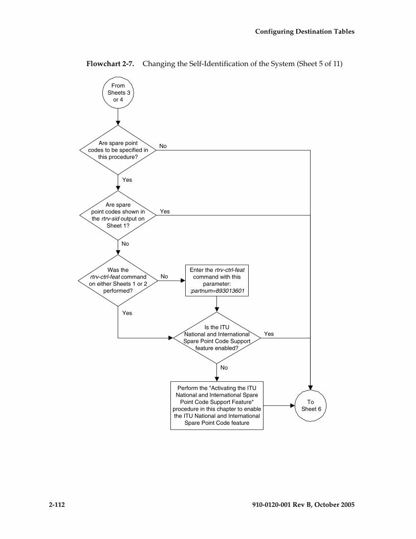
2-112 910-0120-001 Rev B, October 2005
Configuring Destination Tables
Flowchart 2-7. Changing the Self-Identification of the System (Sheet 5 of 11)
Was thertrv-ctrl-feat commandon either Sheets 1 or 2
performed?
No
To Sheet 6
Perform the "Activating the ITUNational and International Spare
Point Code Support Feature"procedure in this chapter to enablethe ITU National and International
Spare Point Code feature
From Sheets 3
or 4
Yes
Are spare pointcodes to be specified in
this procedure?
Are sparepoint codes shown inthe rtrv-sid output on
Sheet 1?
Enter the rtrv-ctrl-featcommand with this
parameter::partnum=893013601
Is the ITUNational and InternationalSpare Point Code Support
feature enabled?
Yes
Yes
Yes
No
No
No

Configuring Destination Tables
910-0120-001 Rev B, October 2005 2-113
Flowchart 2-7. Changing the Self-Identification of the System (Sheet 6 of 11)
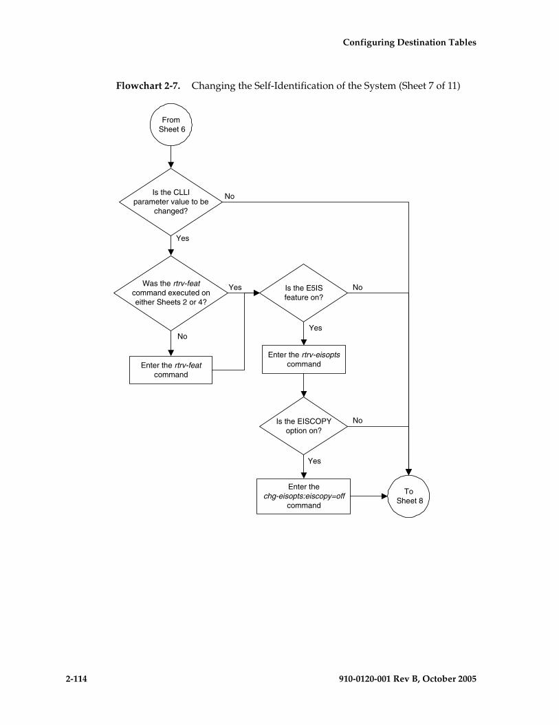
2-114 910-0120-001 Rev B, October 2005
Configuring Destination Tables
Flowchart 2-7. Changing the Self-Identification of the System (Sheet 7 of 11)
Is the E5ISfeature on?
Yes
No
To Sheet 8
Is the CLLIparameter value to be
changed?
Was the rtrv-featcommand executed oneither Sheets 2 or 4?
No
NoYes
Yes
From Sheet 6
Enter the rtrv-featcommand
Enter the rtrv-eisoptscommand
Is the EISCOPYoption on?
Enter thechg-eisopts:eiscopy=off
command
Yes
No
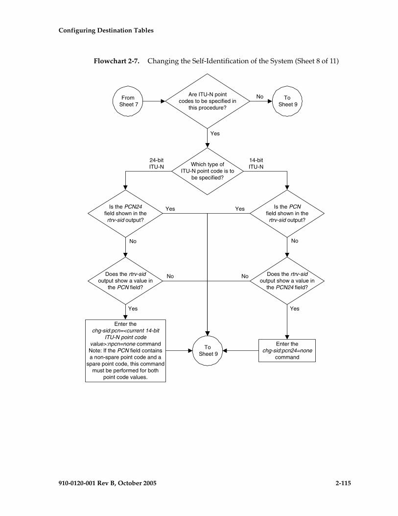
Configuring Destination Tables
910-0120-001 Rev B, October 2005 2-115
Flowchart 2-7. Changing the Self-Identification of the System (Sheet 8 of 11)
From Sheet 7
Are ITU-N pointcodes to be specified in
this procedure?
Enter thechg-sid:pcn=<current 14-bit
ITU-N point codevalue>:npcn=none commandNote: If the PCN field containsa non-spare point code and a
spare point code, this commandmust be performed for both
point code values.
Yes
No
To Sheet 9
Does the rtrv-sidoutput show a value in
the PCN field?
Which type ofITU-N point code is to
be specified?
24-bitITU-N
To Sheet 9
14-bitITU-N
Is the PCN24field shown in thertrv-sid output?
Yes
No
No
Yes
Enter thechg-sid:pcn24=none
command
Does the rtrv-sidoutput show a value in
the PCN24 field?
Is the PCNfield shown in thertrv-sid output?
Yes
No
No
Yes

2-116 910-0120-001 Rev B, October 2005
Configuring Destination Tables
Flowchart 2-7. Changing the Self-Identification of the System (Sheet 9 of 11)
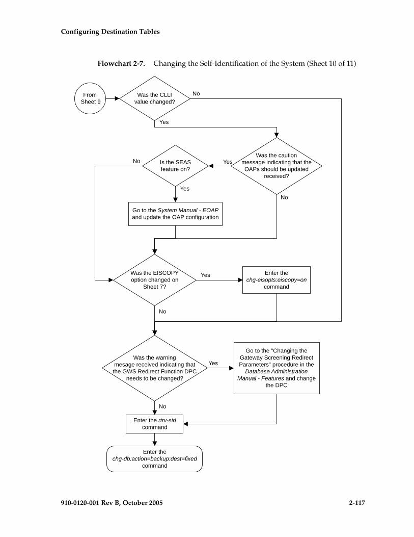
Configuring Destination Tables
910-0120-001 Rev B, October 2005 2-117
Flowchart 2-7. Changing the Self-Identification of the System (Sheet 10 of 11)
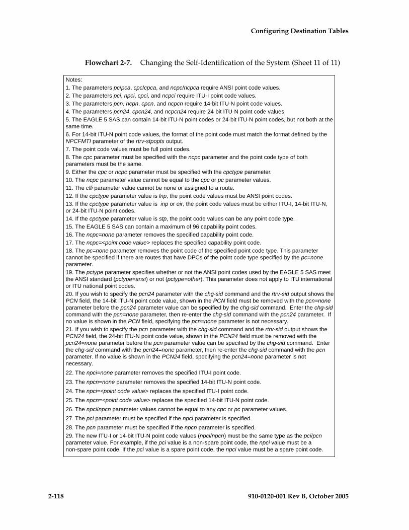
2-118 910-0120-001 Rev B, October 2005
Configuring Destination Tables
Flowchart 2-7. Changing the Self-Identification of the System (Sheet 11 of 11)

Configuring Destination Tables
910-0120-001 Rev B, October 2005 2-119
Cluster Routing and Management Diversity (CRMD)
The Cluster Routing and Management Diversity feature eliminates the need for a full point code entry in the routing table to route to every signaling point in every network. The Cluster Routing and Management Diversity feature allows the EAGLE 5 SAS to configure one routeset to a entire cluster of destinations. This feature also allows the EAGLE 5 SAS to manage and switch traffic to more end nodes.
If the 5000 Routes and 6000 Routesets features are not turned on, the routing table can contain 2000 entries. The 5000 Routes feature allows the routing table to contain up to 5000 entries. The 6000 Routesets feature increases the maximum number of entries to 6000 in the routing table.
A cluster is defined as a group of signaling points whose point codes have identical values for the network and cluster fields of the point codes. A cluster entry in the routing table is shown with an asterisk (*) in the member field of the point code, for example, 111-011-*. With this feature, ANSI destination point codes can be specified as either a full point code, for example, 123-043-045, or as a cluster of signaling point codes, for example, 111-011-*.
NOTE: Cluster entries can only be provisioned as ANSI destination point codes. Cluster entries cannot be provisioned for ITU international or ITU national destination point codes. The ANSI alias point code for an ITU international or ITU national destination point code must be a full point code.
If the X.25 gateway feature is turned on, all ANSI point codes specified as aliases and X.25 destinations must be full point codes and any routes used with the X.25 gateway feature must be defined with a full point code.
The Cluster Routing and Management Diversity feature allows provisioning of clusters, as well as of full point codes that belong to the same cluster as destination point codes (Figure 2-8). The point codes 111-011-*, 111-011-005 and 111-011-045 entries can be provisioned. In Figure 2-8, the cluster destination point code 111-011-* represents all the point codes of the cluster except for point codes 111-011-005 and 111-011-045. Cluster entries in the destination point code table can also be used as a DPC for a route. A group of such routes with varying relative cost forms a routeset to a cluster, just like a routeset to a full point code.

2-120 910-0120-001 Rev B, October 2005
Configuring Destination Tables
Figure 2-8. Cluster Routing and Management Diversity
Exception Lists (X-lists)
An exception list for a cluster is a list of point codes in a cluster whose routes are more restricted than other routes to that cluster. The term “more restricted” is used when comparing the route status of a cluster member to the route status of the cluster. A PROHIBITED status is more restrictive than a RESTRICTED status, and a RESTRICTED status is more restrictive than an ALLOWED status.
This list contains point codes that are not assigned to any individual routeset, and the only routeset to that node is through a cluster routeset. The exception list is a dynamic list that changes when the status of the cluster routesets changes.
The EAGLE 5 SAS allows users to specify whether exception list entries need to be created on a per cluster basis. For each cluster, the user can specify an exception list exclusion indicator (ELEI) when configuring the cluster point code with the ent-dstn command. When the ELEI is yes, the EAGLE 5 SAS does not create exception list entries or remove any existing exception list entries for the given cluster. When the ELEI is no, the EAGLE 5 SAS creates and removes exception list entries. When the ELEI is no, it is not guaranteed that there will be space available to create each and every possible exception list entry for provisioned cluster entries. All such exception list entries must compete for available exception list space.
Cluster 111-011-*
123-043-045
133-034-034
111-011-005
111-011-045

Configuring Destination Tables
910-0120-001 Rev B, October 2005 2-121
Exception list entries are stored as an extension of the Destination Point Code table. The Destination Point Code table can contain a maximum number of entries, as follows:
• 2500 entries if the 5000 Routes feature is not turned on and 6000, 7000, or 8000 routesets are not enabled.
• 5500 entries if the 5000 Routes feature is turned on and 6000, 7000, or 8000 routesets are not enabled.
• 6500 entries if 6000 routesets are enabled.
• 7500 entries if 7000 routesets are enabled.
• 8500 entries if 8000 routesets are enabled.
The EAGLE 5 SAS allows the user to specify the number of entries reserved for the exception list. The remainder of the entries in the Destination Point Code table are reserved for configured destinations (the full and cluster point codes).
• If the 5000 Routes feature is off and 6000, 7000, or 8000 routesets are not enabled, the Destination Point Code table can contain up to 2500 entries. The exception list can contain from 500 to 2000 entries. The maximum number of entries reserved for configured destinations (full and cluster point codes) is 2500 minus the number of entries reserved for the exception list.
• If the 5000 Routes feature is on and 6000, 7000, or 8000 routesets are not enabled, the Destination Point Code table can contain up to 5500 entries. The exception list can contain from 500 to 5000 entries. The maximum number of entries reserved for configured destinations (full and cluster point codes) is 5500 minus the number of entries reserved for the exception list.
• If 6000 routesets are enabled, the Destination Point Code table can contain up to 6500 entries. The exception list can contain from 500 to 6000 entries. The maximum number of entries reserved for configured destinations (full and cluster point codes) is 6500 minus the number of entries reserved for the exception list.
• If 7000 routesets are enabled, the Destination Point Code table can contain up to 7500 entries. The exception list can contain from 500 to 7000 entries. The maximum number of entries reserved for configured destinations (full and cluster point codes) is 7500 minus the number of entries reserved for the exception list.
• If 8000 routesets are enabled, the Destination Point Code table can contain up to 8500 entries. The exception list can contain from 500 to 8000 entries. The maximum number of entries reserved for configured destinations (full and cluster point codes) is 8500 minus the number of entries reserved for the exception list.

2-122 910-0120-001 Rev B, October 2005
Configuring Destination Tables
The outputs of the ent-dstn, dlt-dstn, chg-dstn, and rtrv-dstn commands display this destination point code usage information:
• The number of configured full point codes
• The number of configured cluster point codes
• The number of configured network routing point codes
• The sum of configured destinations (full, network routing, and cluster point codes)
• The number of DPCs the EAGLE 5 SAS may contain (full, network routing, and cluster point codes). This number is the value of the chg-stpopts command’s mtpdpcq parameter. This number is not always the maximum number of entries minus the number reserved for the exception list. This calculation determines the maximum number of DPCs the EAGLE 5 SAS may contain. The mtpdpcq parameter value of the chg-stpopts command determines the actual number of DPCs the EAGLE 5 SAS can have, and can be set to an amount less than the maximum.
• The number of entries reserved for exception list. This number is the value of the chg-stpopts command’s mtpxlq parameter.
• The number of alias point codes the EAGLE 5 SAS may contain - 8000 or 12000. If 7000 or 8000 routesets are enabled, the EAGLE 5 SAS can contain a maximum of 8000 alias point codes. If 7000 or 8000 routesets are not enabled, the EAGLE 5 SAS can contain a maximum of 12000 alias point codes.
• The number of alias point codes configured in the EAGLE 5 SAS.
Exception list entries have an expiration timer. There is a single EAGLE 5 SAS-wide expiration timer value for exception list entries. The exception list expiration timer, the size of the exception list, and the percentage of occupancy that generates a minor alarm can be configured with the chg-stpopts command. The values are shown in these fields of the rtrv-stpopts command output:
MTPXLQ = the maximum number of entries the exception list (x-list) can contain.
MTPXLET = the maximum amount of time the EAGLE 5 SAS will maintain an unreferenced exception list (x-list) entry
MTPXLOT = the exception list (x-list) occupancy threshold (in terms of percentage of space available). If this threshold is exceeded, the EAGLE 5 SAS raises a minor alarm. The percentage of occupancy refers to the number of exception list entries as compared to the maximum number of entries the exception list can hold. For example, if there are 1500 entries configured for the exception list and the exception list contains 1000 entries, the percentage

Configuring Destination Tables
910-0120-001 Rev B, October 2005 2-123
of the exception list space being used is 66%. If this threshold is exceeded, the EAGLE 5 SAS raises a minor alarm.
The EAGLE 5 SAS raises a major alarm when the exception list becomes completely full and the EAGLE 5 SAS fails to create any more exception list entries.
MTPDPCQ = the maximum number of destination point codes that can be configured in the EAGLE 5 SAS.
NOTE: The sum of the MTPDPCQ and MTPXLQ values cannot exceed one of these totals depending on the features that are enabled or turned on:
• 2500 – if the 5000 Routes feature is not on, and 6000, 7000, or 8000 routesets are not enabled.
• 5500 – if the 5000 Routes feature is on, but 6000, 7000, or 8000 routesets are not enabled.
• 6500 – if 6000 routesets are enabled.
• 7500 – if 7000 routesets are enabled.
• 8500 – if 8000 routesets are enabled.
An exception list entry’s timer is restarted when an exception list entry gets created, updated, or used for routing. This expiration timer (the mtpxlet parameter in the chg-stpopts command) can be set from a minimum of 20 minutes to a maximum of 24 hours. The default value for the expiration timer upon EAGLE 5 SAS start-up is 60 minutes. If the timer expires before it is restarted, the exception list entry is removed. The expiration timer allows the EAGLE 5 SAS to save resources, if the exception list entry is sitting idle for a long time.
An exception list entry can be created for three distinct set of conditions:
1. The first set of conditions creates exception list entries based on the status of the route (allowed, restricted, or prohibited), and these entries are marked as “exception list due to routing.”
2. The EAGLE 5 SAS creates an exception list entry to maintain the congestion status of a non-provisioned, cluster-routed destination point code. These entries are marked “exception list due to congestion.”
3. The EAGLE 5 SAS also creates an exception list to prohibit routing to a member of a cluster when circular routing to that member is detected. These exception list entries are marked “exception list due to circular routing.”

2-124 910-0120-001 Rev B, October 2005
Configuring Destination Tables
An exception list entry for a particular cluster can be removed from the exception list when these conditions are met:
1. The status of all routes to the specified point code changes to a status that is less or equally restrictive than the corresponding status of the cluster’s routes. This can happen for two reasons.
a. A dact-rstst command was issued.
b. A network management message (TFA or TFR) was received indicating the new status of the route to the specified point code.
2. The expiration timer for the exception list entry expires.
3. When a chg-dstn command is issued and changes the ELEI to yes for the cluster, and the EAGLE 5 SAS removes all exception list entries created for that cluster.
4. The chg-stpopts command was issued with the mtpxlet parameter, and the new value for the mtpxlet parameter was smaller than the original value. This command can change the allocation of routing table entries for the exception list. If the size of the exception list is reduced and the number of entries in the exception list is now greater than the new value of the mtpxlet parameter, the EAGLE 5 SAS will remove excess exception list entries at random.
5. When the user allows a circular routed “exception list due to circular routing” entry.
6. When congestion abates for an “exception list due to routing” entry.
Cluster Routing
When the EAGLE 5 SAS receives an MSU to route, the routing function looks for the MSU’s destination point code as a full point code entry in the routing table. If found, the full point code entry is used to find the corresponding routeset and the outgoing route. If a full point code entry is not found, the routing function uses the destination point code’s network and cluster values to find a cluster entry to which the destination point code belongs. If found, the cluster entry is used to find the corresponding routeset and the outgoing route. If neither a full point code entry or cluster point code entry is found, the EAGLE 5 SAS generates UAM 1004, “MTP rcvd unknown DPC.”

Configuring Destination Tables
910-0120-001 Rev B, October 2005 2-125
Compatibility with Non-Cluster Routing Nodes
It is possible that not all of the nodes in the network that the EAGLE 5 SAS is operating in are cluster routing nodes. In such a situation, those nodes not doing cluster routing will interpret TCx messages, and apply them to each individual point code belonging to the concerned cluster. This may cause an inconsistency in the status records for exception-listed point codes in different nodes. In order to avoid this situation, the EAGLE 5 SAS takes these steps:
1. After broadcasting a TCR message for a cluster, the EAGLE 5 SAS stops any level 3 T8 timers running for exception-listed members of the cluster, and enables TFPs for the cluster’s exception-listed (prohibited) member point codes by stopping the level 3 T8 timer. This allows TFPs to be sent for prohibited members immediately after a TCR is broadcast.
2. After broadcasting a TCA message for a cluster, the EAGLE 5 SAS enables a one-time TFR for the cluster’s exception-listed (restricted) member point codes by stopping the level 3 T18 timer, and enables the TFPs for the cluster’s exception-listed (prohibited) member point codes by stopping the level 3 T8 timer. This allows TFPs to be sent for prohibited members, and TFRs for restricted members, immediately after a TCA is broadcast.
Cluster Management and the ITU Network
ITU SS7 networks do not use the concepts of clusters of point codes and cluster network management messages. The EAGLE 5 SAS does not generate TCx messages toward ITU nodes. When the EAGLE 5 SAS is acting as gateway between an ITU network and an ANSI network, during the broadcast phase of TCx messages, the EAGLE 5 SAS does not send TCx messages to adjacent ITU point codes. It is possible that messages may be lost in such a case. In order to reduce message loss and quickly notify the sending ITU node about the status, the EAGLE 5 SAS enables TFPs or TFRs immediately (with the level 3 T8 or T18 timers stopped) and relies on the TFPs or TFRs to convey the status information.
While sending response method network management messages in response to a received MSU, the EAGLE 5 SAS checks the MSU’s originating point code. If the MSU’s originating point code is an ITU point code, a TFx message is returned.

2-126 910-0120-001 Rev B, October 2005
Configuring Destination Tables
Cluster Management When the Cluster Routing Feature is Turned Off
The Cluster Routing and Management Diversity feature is an optional feature that is turned off by default. To use the Cluster Routing and Management Diversity feature, it must be turned on by entering the appropriate command. Once this feature is turned on, it cannot be turned off. If this feature is turned off, the EAGLE 5 SAS does not send any cluster management messages or allow cluster destination point codes to be added to the destination point code table. The EAGLE 5 SAS is capable of processing incoming cluster management messages, even though the feature is turned off. When a cluster management message is received, the EAGLE 5 SAS treats this message as though network management messages were received for each full point code, configured in the destination point code table, that belongs to that cluster.
Cluster Routing and Management Diversity Rules
These rules apply to the Cluster Routing and Management Diversity feature:
• If the provisioned number of exception list entries are already created, the EAGLE 5 SAS will not create any more exception list entries. The EAGLE 5 SAS raises an alarm in advance of such an occurrence, and pegs each occurrence of failure-to-create an exception list entry.
• All adjacent point codes for linksets must be full point codes.
• All entries in the remote point code table must be a full point code.
• For X.25 destinations, the DPCs associated with the X.25 addresses must be full point codes and the DPCs of the routes associated with any X.25 routes must have full point codes.
• The EAGLE 5 SAS maintains the congestion status of only 100 destinations, including full point codes and point codes to which cluster routing is performed.
• When the cluster routing feature is turned on, and the EAGLE 5 SAS receives an MSU and does not find a route with a full point code, a cluster route, or any other full point code route belonging to the cluster, the EAGLE 5 SAS will generate a TCP response.
• When the cluster routing feature is turned off, and the EAGLE 5 SAS receives an MSU and does not find a route with a full point code, the EAGLE 5 SAS will generate a TFP response.
When the EAGLE 5 SAS is used as an ITU-ANSI gateway STP:
• The EAGLE 5 SAS does not broadcast TCx messages towards the ITU nodes. Messages could be lost until the response method is initiated. It is recommended that the cluster routing feature not be turned on when the EAGLE 5 SAS is an ITU gateway STP.

Configuring Destination Tables
910-0120-001 Rev B, October 2005 2-127
• Cluster destination point codes cannot have ITU alias point codes.
All ANSI alias point codes specified for real ITU point codes are required to be full point codes.
The point code specified in the ent-map command must use a full point code, and that full point code must be in the routing table.
The point code specified in the ent-gtt and ent-cspc commands can use either a full point code or a cluster point code, but these point codes must be in the routing table.
The EAGLE 5 SAS allows cluster routing for subsequent global title (GTT) messages. The EAGLE 5 SAS also sends subsystem status messages to concerned point codes using a cluster route. The EAGLE 5 SAS does not generate MTP status messages for point codes that the EAGLE 5 SAS is routing clusters to, so all point codes in the mated application table must be full point codes.
Gateway screening verifies the concerned point code in TFx/RSx messages received by the EAGLE 5 SAS. Gateway screening passes a TFx/RSx message through the MTP-affected destination test, if the concerned point code has either a full point code route or a cluster route.
Gateway screening verifies the concerned point code in TCx/RCx messages received by the EAGLE 5 SAS. Gateway screening passes a TCx/RCx message through the MTP-affected destination test, if the concerned point code has either a cluster route for a concerned cluster or a member route for any of the members of the concerned cluster.
The EAGLE 5 SAS verifies that all destinations (X.25 destinations and SS7 destinations) used by the X.25 gateway feature have a full point code route available. The EAGLE 5 SAS does not allow the use of cluster routes to destinations used by the X.25 gateway feature because of these reasons:
• When SS7 destinations are routed using a cluster route, the EAGLE 5 SAS does not generate the MTP-PAUSE and MTP-RESUME indications for individual point codes of that cluster. These indications are required by the X.25 gateway feature to tear down virtual circuits in the case of inaccessibility to the node in SS7 network.
• When X.25 destinations are routed using a cluster route, there are chances of a transient flood of TFP messages and consequent TFA messages when the X.25 gateway feature is restarting. This results in a transient flood of exception list entries and degrades the EAGLE 5 SAS’s performance and results in traffic loss.
If a point code is in the routing table as an exception-listed point code and the user enters a command (ent-dstn) to configure that same point code as a full point code, the exception-listed point code attribute is changed to a full point code attribute, and the exception-list related information from the cluster entry is updated.

2-128 910-0120-001 Rev B, October 2005
Configuring Destination Tables
When a cluster destination point code is removed from the EAGLE 5 SAS’s database, all related exception-listed point codes of that cluster are removed.
The EAGLE 5 SAS implements these protocol features that are non-preferred options:
• The EAGLE 5 SAS broadcasts a TFP, when a full point code is prohibited and these conditions apply:
a. The corresponding cluster is not provisioned.
b. All other full point codes belonging to the same cluster are prohibited on the same route.
• The EAGLE 5 SAS responds with a TFP, when a message is received for an inaccessible point code and the corresponding cluster does not exist.
• Upon receiving a TCR message for a cluster that is not configured, the EAGLE 5 SAS marks all individually configured members of that cluster as restricted, and starts the RSR procedure for them.
• Upon receiving a TCP message for a cluster that is not provisioned, the EAGLE 5 SAS marks all individually configured members of that cluster as prohibited, and starts the RSP procedure for them.
• The EAGLE 5 SAS stops the level 3 T8 and T18 timers, after broadcasting a TCA for prohibited and restricted members of the clusters. These members can be exception-listed point codes or full point codes.
• The EAGLE 5 SAS stops the level 3 T8 timers after broadcasting a TCR for prohibited members of the clusters. These members can be exception-listed point codes or full point codes.
The route assigned to a full point code DPC cannot be removed from the database if that DPC is a member of a cluster point code in the database.
If a route assigned to a cluster point code is removed from the database, all routes to any members of that cluster are also removed from the database.
Cluster Routing and Management Diversity Example
This section shows an example of the Cluster Routing and Management Diversity feature, and lists the network events affecting the EAGLE 5 SAS. This example is based on Figure 2-9 and Table 2-3.

Configuring Destination Tables
910-0120-001 Rev B, October 2005 2-129
Figure 2-9. Cluster Management
When the normal routes, linksets LSN 1 and LSN 2, become available, the EAGLE 5 SAS sends a preventive TFP for destination 005-005-001 and a preventive TCP for cluster 005-005-* to node 002-002-002, and starts routing messages to destination 005-005-001 and cluster 005-005-* using linkset LSN 1. The EAGLE 5 SAS broadcasts TFAs about destination 005-005-001 and TCAs about cluster 005-005-* to all other adjacent nodes.
1. When linkset LSN 4 fails, node 002-002-002 sends a TFP for destination 005-005-001 to the EAGLE 5 SAS. Linkset LSN 4 is prohibited from carrying traffic from the EAGLE 5 SAS to destination 005-005-001. The EAGLE 5 SAS stops using linkset LSN 1 to send traffic to destination 005-005-001, performs forced rerouting, starts level 3 timer T11 for destination 005-005-001, and starts using linkset LSN 2 to send messages to destination 005-005-001. The EAGLE 5 SAS generates preventive TFPs about destination 005-005-001 to node 002-002-003. The preventive TCP for cluster 005-005-* sent to node 002-002-002 remains in effect.
When the level 3 timer T11 for destination 005-005-001 expires, TFRs are broadcast for destination 005-005-001 to nodes 004-004-004, 006-006-006, 007-007-007, and 008-008-008. Destination 005-005-001 is restricted.
2. When linkset LSN 5 fails, node 002-002-002 sends a TCP for cluster 005-005-* to the EAGLE 5 SAS. Linkset LSN 5 is prohibited from carrying traffic from the EAGLE 5 SAS to cluster 005-005-*. The EAGLE 5 SAS stops using linkset LSN 1 to send traffic to cluster 005-005-*, performs forced rerouting, starts the
Table 2-3. Example Cluster Routing Information
Route Table for Destination 005-005-001
Route Table for Cluster 005-005-*
1 LSN 1, Cost=10 LSN 1, Cost=10
2 LSN 2, Cost=15 LSN 2, Cost=15
3 LSN 3, Cost=20 LSN 3, Cost=20
LSN 1
LSN 2
Cost=10
Cost=15
LSN 3Cost=20
LSN 5
LSN 6
LSN 7
LSN 4
001-001-001
002-002-002
003-003-003
004-004-004
Cluster005-005-*
005-005-001
005-005-002
005-005-003
006-006-006
007-007-007
008-008-008
2-130 910-0120-001 Rev B, October 2005
Configuring Destination Tables
level 3 timer T11 for cluster 005-005-*, and starts using linkset LSN 2 to send messages to cluster 005-005-*. The EAGLE 5 SAS sends preventive TCPs for cluster 005-005-* on linkset LSN 2. The EAGLE 5 SAS sends a TCR for cluster 005-005-* on linkset LSN 1, to allow cluster 005-005-* and destination 005-005-001 to send messages back to the EAGLE 5 SAS on linkset LSN 1. When the level 3 timer T11 for cluster 005-005-* expires, the EAGLE 5 SAS sends a TCR for cluster 005-005-* to nodes 004-004-004, 006-006-006, 007-007-007, and 008-008-008. Cluster 005-005-* is restricted.
3. When linkset LSN 6 fails, node 003-003-003 sends a TCP for cluster 005-005-* to the EAGLE 5 SAS. The EAGLE 5 SAS performs forced rerouting, sends a preventive TFP for destination 005-005-001 and a TCP for destination 005-005-001 to node 004-004-004, and starts using linkset LSN 3 for sending messages to destination 005-005-001 and cluster 005-005-*.
4. When linkset LSN 7 fails, node 004-004-004 sends a TCP for cluster 005-005-* to EAGLE 5 SAS. The EAGLE 5 SAS cannot send traffic to either destination 005-005-001 or cluster 005-005-*. The EAGLE 5 SAS broadcasts TCPs for cluster 005-005-* to nodes 002-002-002, 003-003-003, 004-004-004, 006-006-006, 007-007-007, and 008-008-008. Cluster 005-005-* and destination 005-005-001 are inaccessible.
5. When linkset LSN 7 recovers, node 004-004-004 sends a TCA for cluster 005-005-* to the EAGLE 5 SAS. The EAGLE 5 SAS sends a preventive TCP for cluster 005-005-* to node 004-004-004, and starts using linkset LSN 3 to send traffic to cluster 005-005-*. The EAGLE 5 SAS sends a TCR for cluster 005-005-* to node 002-002-002. This allows cluster 005-005-* to send messages back to the EAGLE 5 SAS on linkset LSN 3. The EAGLE 5 SAS sends a preventive TCP for cluster 005-005-* to nodes 003-003-003 and 004-004-004. The EAGLE 5 SAS sends a TCR for cluster 005-005-* to nodes 006-006-006, 007-007-007, and 008-008-008. The EAGLE 5 SAS enables response method for destination 005-005-001, and starts a routeset test for destination 005-005-001 on linkset LSN 3. Cluster 005-005-* is restricted.
6. When linkset LSN 6 recovers, node 003-003-003 sends a TCA for cluster 005-005-* to the EAGLE 5 SAS. The EAGLE 5 SAS performs controlled rerouting on cluster 005-005-*, sends a preventive TCP for cluster 005-005-* to node 003-003-003, and starts using linkset LSN 2 to send traffic to cluster 005-005-*. The EAGLE 5 SAS sends a TCR for cluster 005-005-* to node 004-004-004. The EAGLE 5 SAS starts a routeset test for destination 005-005-001 on linkset LSN 2.
Configuring Destination Tables
910-0120-001 Rev B, October 2005 2-131
7. When linkset LSN 5 recovers, node 002-002-002 sends a TCA for cluster 005-005-* to the EAGLE 5 SAS. The EAGLE 5 SAS performs controlled rerouting, and starts using linkset LSN 1 to send traffic to cluster 005-005-*. The EAGLE 5 SAS sends a preventive TCP for cluster 005-005-* to node 002-002-002. The EAGLE 5 SAS broadcasts a TCA for cluster 005-005-* to nodes 003-003-003, 004-004-004, 006-006-006, 007-007-007, and 008-008-008. The EAGLE 5 SAS enables response method for destination 005-005-001, and starts a routeset test for destination 005-005-001 on linkset LSN 1. Cluster 005-005-* is allowed.
8. In response to the routeset test, node 004-004-004 sends a TFA for destination 005-005-001 to the EAGLE 5 SAS. The EAGLE 5 SAS performs controlled rerouting, and starts using linkset LSN 3 to send traffic to destination 005-005-001. The EAGLE 5 SAS sends a preventive TFP for destination 005-005-001 to nodes 003-003-003 and 004-004-004. The EAGLE 5 SAS sends a TFR for destination 005-005-001 to node 002-002-002 that allows destination 005-005-001 to send messages back to the EAGLE 5 SAS on linkset LSN 1. The EAGLE 5 SAS broadcasts a TFR for destination 005-005-001 to nodes 006-006-006, 007-007-007, and 008-008-008. Destination 005-005-001 is restricted.
9. In response to the routeset test, node 003-003-003 sends a TFA for destination 005-005-001 to the EAGLE 5 SAS. The EAGLE 5 SAS performs controlled rerouting and starts using linkset LSN 2 to send traffic to destination 005-005-001. The EAGLE 5 SAS sends a preventive TFP for destination 005-005-001 to node 003-003-003. The EAGLE 5 SAS sends a TFR for destination 005-005-001 to node 004-004-004.
10. In response to the routeset test, node 002-002-002 sends a TFA for destination 005-005-001 to the EAGLE 5 SAS. The EAGLE 5 SAS performs controlled rerouting, and starts using linkset LSN 1 to send traffic to destination 005-005-001. The EAGLE 5 SAS sends a preventive TFP for destination 005-005-001 to node 002-002-002. The EAGLE 5 SAS sends a TFA for destination 005-005-001 to nodes 003-003-003, 004-004-004, 006-006-006, 007-007-007, and 008-008-008. Destination 005-005-001 is allowed.
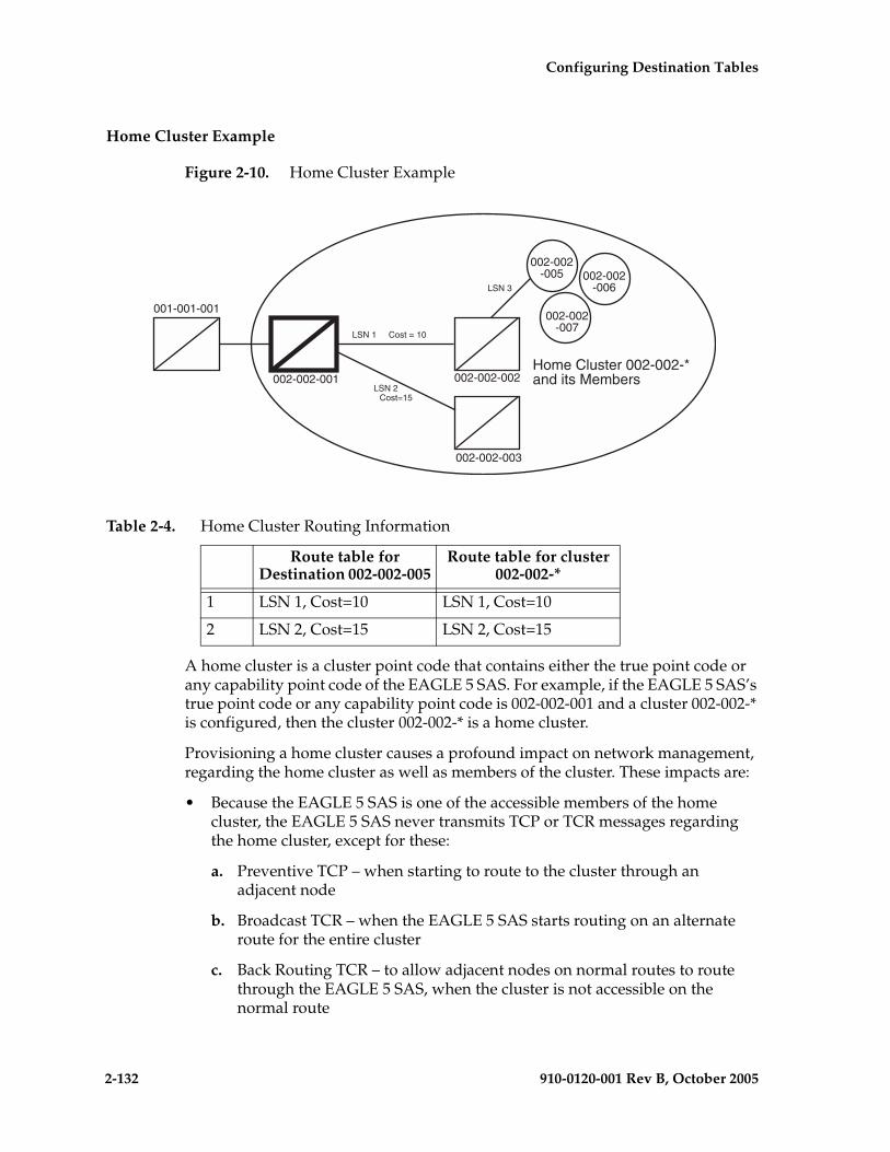
2-132 910-0120-001 Rev B, October 2005
Configuring Destination Tables
Home Cluster Example
Figure 2-10. Home Cluster Example
A home cluster is a cluster point code that contains either the true point code or any capability point code of the EAGLE 5 SAS. For example, if the EAGLE 5 SAS’s true point code or any capability point code is 002-002-001 and a cluster 002-002-* is configured, then the cluster 002-002-* is a home cluster.
Provisioning a home cluster causes a profound impact on network management, regarding the home cluster as well as members of the cluster. These impacts are:
• Because the EAGLE 5 SAS is one of the accessible members of the home cluster, the EAGLE 5 SAS never transmits TCP or TCR messages regarding the home cluster, except for these:
a. Preventive TCP – when starting to route to the cluster through an adjacent node
b. Broadcast TCR – when the EAGLE 5 SAS starts routing on an alternate route for the entire cluster
c. Back Routing TCR – to allow adjacent nodes on normal routes to route through the EAGLE 5 SAS, when the cluster is not accessible on the normal route
Table 2-4. Home Cluster Routing Information
Route table for Destination 002-002-005
Route table for cluster 002-002-*
1 LSN 1, Cost=10 LSN 1, Cost=10
2 LSN 2, Cost=15 LSN 2, Cost=15
Home Cluster 002-002-*and its Members
LSN 1 Cost = 10
LSN 2
LSN 3
Cost=15
001-001-001
002-002-001 002-002-002
002-002-003
002-002-005 002-002
-006
002-002-007
Configuring Destination Tables
910-0120-001 Rev B, October 2005 2-133
d. Broadcast TCP – when the cluster (except the EAGLE 5 SAS itself) becomes inaccessible
• If individual members are provisioned for the home cluster, the EAGLE 5 SAS properly generates network management messages for these nodes, except that no TFRs can be sent from those members being routed on the alternate route to the EAGLE 5 SAS.
• Network management replies to the routeset test, and the response method generates the correct network management messages for the home cluster, its members, and unprovisioned member point codes.
• When the entire home cluster is being routed on the alternate route, the EAGLE 5 SAS generates a full point code response method TFR reply. In such a case, the EAGLE 5 SAS generates only one TFR for the very first member of the cluster for which MSU is received on each signaling link to that cluster.
• When the home cluster is inaccessible, the EAGLE 5 SAS generates one response TFP, at an interval equal to the value of the level 3 timer T8 for the members of the home cluster. If the EAGLE 5 SAS keeps receiving traffic for the home cluster, the EAGLE 5 SAS sends response TFPs for all members of the cluster.
This makes network management unreliable for the home cluster and its members.
When the normal routes, linksets LSN 1 and LSN 2, become available, the EAGLE 5 SAS sends a preventive TFP for destination 002-002-005 to node 002-002-002, and starts sending messages to destination 002-002-005 and cluster 002-002-* using linkset LSN 1. No preventive messages are sent for cluster 002-002-*. The EAGLE 5 SAS broadcasts a TFA for destination 002-002-005 and a TCA for cluster 002-002-* to all other adjacent nodes.
1. Node 002-002-002 sends an MSU containing the destination point code 002-002-006 on linkset LSN 1. The EAGLE 5 SAS responds with a response preventive TFP for destination 002-002-006 to node 002-002-002.
2. When linkset LSN 3 fails, node 002-002-002 sends a TFP for destination 002-002-005 to the EAGLE 5 SAS. The EAGLE 5 SAS stops using linkset LSN 1 to send traffic to destination 002-002-005, performs forced rerouting, starts the level 3 timer T11 for destination 002-002-005, and starts using linkset LSN 2 to send traffic to destination 002-002-005. The EAGLE 5 SAS generates a preventive TFP for destination 002-002-005 to node 002-002-003. When the level 3 timer T11 for destination 002-002-005 expires, TFRs for destination 002-002-005 are broadcast to nodes 002-002-003 and 001-001-001. Destination 002-002-005 is restricted.

2-134 910-0120-001 Rev B, October 2005
Configuring Destination Tables
3. Node 002-002-002 sends an MSU containing the destination point code 002-002-005 on linkset LSN 1. The EAGLE 5 SAS responds with a response preventive TFP for destination 002-002-005 to node 002-002-002, because no member of a home cluster is allowed to route messages back to the EAGLE 5 SAS.
4. When linkset LSN 1 fails, the EAGLE 5 SAS stops using linkset LSN 1 to send traffic to cluster 002-002-*, performs forced rerouting, starts the level 3 timer T11 for cluster 002-002-*, and starts using linkset LSN 2 to send traffic to cluster 002-002-*. Cluster 002-002-* is restricted. No preventive or broadcast messages are sent, and no member of the cluster is allowed to send messages back to the EAGLE 5 SAS.
5. Node 001-001-001 sends an MSU containing the destination point code 002-002-006. The EAGLE 5 SAS responds with a response TFR for destination 002-002-006 to node 001-001-001. The MSU is routed on linkset LSN 2.
6. Node 001-001-001 sends an MSU containing the destination point code 002-002-005. The EAGLE 5 SAS responds with a response TFR for destination 002-002-005 to node 001-001-001. The MSU is routed on linkset LSN 2.
7. Node 001-001-001 sends an MSU containing the destination point code 002-002-007 and receives no response. The MSU is routed on linkset LSN 2.
8. When linkset LSN 2 fails, destination 002-002-005 and cluster 002-002-* are prohibited. The EAGLE 5 SAS broadcasts a TFP for destination 002-002-005 to node 001-001-001.
9. Node 001-001-001 sends an MSU containing the destination point code 002-002-007. The EAGLE 5 SAS responds with a TFP for destination 002-002-007 to node 001-001-001, and starts the level 3 timer T8 for cluster 002-002-*.
10. Node 001-001-001 sends an MSU containing the destination point code 002-002-006, and receives no response until the level 3 timer T8 expires.
11. Node 001-001-001 sends an MSU containing the destination point code 002-002-005. The EAGLE 5 SAS responds with a TFP for destination 002-002-005 to node 001-001-001, and starts the level 3 timer T8 for destination 002-002-005.
12. Node 001-001-001 sends an MSU containing the destination point code 002-002-006. After the level 3 timer T8 for cluster 002-002-* expires, the EAGLE 5 SAS responds with a TFP for destination 002-002-006 to node 001-001-001, and starts the level 3 timer T8 for cluster 002-002-*.
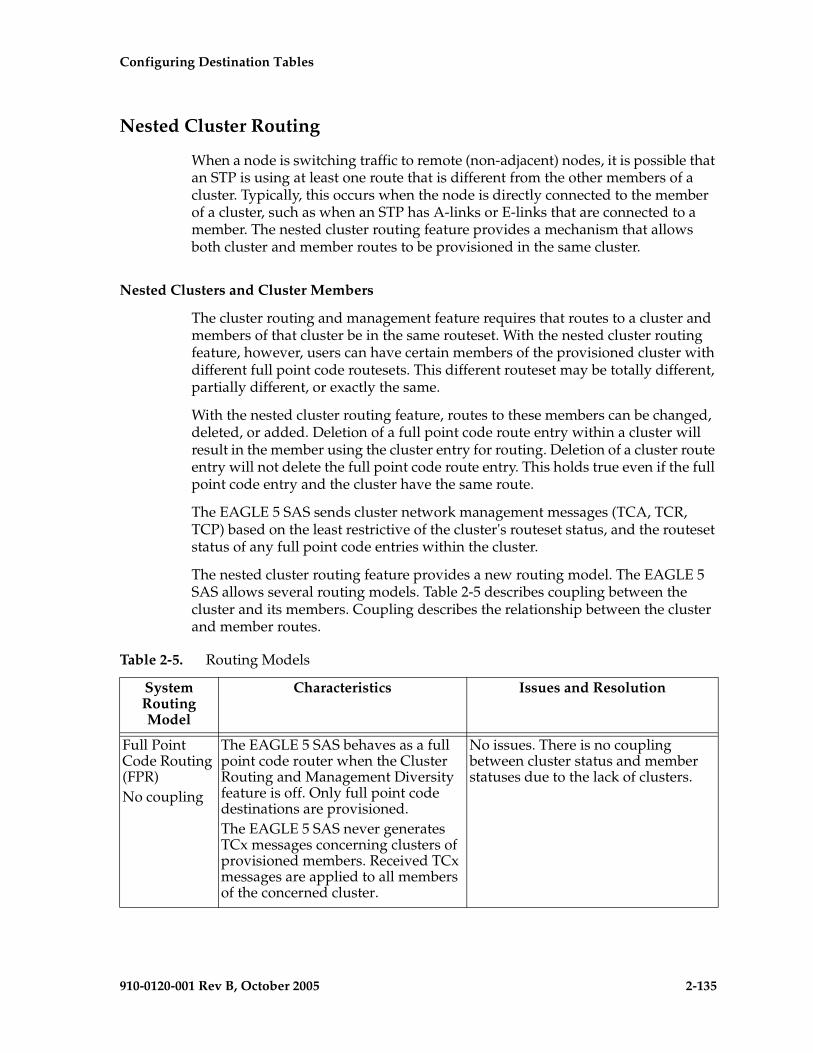
Configuring Destination Tables
910-0120-001 Rev B, October 2005 2-135
Nested Cluster Routing
When a node is switching traffic to remote (non-adjacent) nodes, it is possible that an STP is using at least one route that is different from the other members of a cluster. Typically, this occurs when the node is directly connected to the member of a cluster, such as when an STP has A-links or E-links that are connected to a member. The nested cluster routing feature provides a mechanism that allows both cluster and member routes to be provisioned in the same cluster.
Nested Clusters and Cluster Members
The cluster routing and management feature requires that routes to a cluster and members of that cluster be in the same routeset. With the nested cluster routing feature, however, users can have certain members of the provisioned cluster with different full point code routesets. This different routeset may be totally different, partially different, or exactly the same.
With the nested cluster routing feature, routes to these members can be changed, deleted, or added. Deletion of a full point code route entry within a cluster will result in the member using the cluster entry for routing. Deletion of a cluster route entry will not delete the full point code route entry. This holds true even if the full point code entry and the cluster have the same route.
The EAGLE 5 SAS sends cluster network management messages (TCA, TCR, TCP) based on the least restrictive of the cluster's routeset status, and the routeset status of any full point code entries within the cluster.
The nested cluster routing feature provides a new routing model. The EAGLE 5 SAS allows several routing models. Table 2-5 describes coupling between the cluster and its members. Coupling describes the relationship between the cluster and member routes.
Table 2-5. Routing Models
SystemRoutingModel
Characteristics Issues and Resolution
Full Point Code Routing (FPR)No coupling
The EAGLE 5 SAS behaves as a full point code router when the Cluster Routing and Management Diversity feature is off. Only full point code destinations are provisioned.The EAGLE 5 SAS never generates TCx messages concerning clusters of provisioned members. Received TCx messages are applied to all members of the concerned cluster.
No issues. There is no coupling between cluster status and member statuses due to the lack of clusters.

2-136 910-0120-001 Rev B, October 2005
Configuring Destination Tables
Cluster Routing (CR)No couplingNCAI=No
With the Cluster Routing and Management Diversity feature on, the EAGLE 5 SAS allows the provisioning of cluster destinations. For cluster destinations, only cluster destinations are provisioned. The EAGLE 5 SAS generates TCx messages only for provisioned cluster destinations. All received TCx messages are applied to concerned cluster entry, if it exists. Otherwise, it is applied to all individual members.
No issues. There is no coupling between cluster status and member status due to the lack of members belonging to provisioned cluster.
Cluster Routing and Management Diversity (CRMD)Full couplingNCAI=No
In this mode, the EAGLE 5 SAS allows provisioning of clusters as well as members of same clusters. Here cluster and member have the same routeset, and they are fully coupled.All TCx messages are applied to members, and TCx messages generated by the EAGLE 5 SAS reflect member status. In this mode, the member status cannot be less restrictive than the cluster.
No issues regarding network management message generation and processing. Cluster and members cannot have a different routeset, and thus E-links cannot be provisioned for members of a cluster.
Nested Cluster RoutingNo couplingNCAI=Yes
In this mode, if the ncai parameter is yes (provided both the nested cluster routing and the Cluster Routing and Management Diversity features are on), the user can enter a cluster routeset, then enter a different routeset for a member of that cluster. In this case, member routeset status can be less restricted than cluster routeset status.
There is an issue regarding broadcasting network management messages. Because members can be less restricted than the cluster, the broadcast of cluster messages (TCA, TCR, TCP) is based on the least restrictive of the following:• The cluster’s routeset status.• The routeset status of any full
point code entries within the cluster.
• Also, when the ncai parameter is yes, the EAGLE 5 SAS does not generate preventive TCP messages.
Table 2-5. Routing Models (Continued)
SystemRoutingModel
Characteristics Issues and Resolution
Configuring Destination Tables
910-0120-001 Rev B, October 2005 2-137
Administration
The nested cluster routing feature is provisioned using the ncai parameter of either the ent-dstn or chg-dstn commands. The ncai parameter can only be specified for cluster point codes.
In order to specify the ncai parameter, both the Cluster Routing and Management Diversity and the nested cluster routing features must be on. If the ncai parameter is yes, the EAGLE 5 SAS allows certain members of the provisioned cluster to have a different full point code routeset.
If the ncai parameter is no, standard command-handler rules apply (any full point code routeset within a cluster must have the same routeset as the cluster). If ncai parameter is yes, new command-handler rules apply (full point code routeset can be different from the cluster routeset). Figure 2-11 provides an example of provisioning a nested cluster and its associated members.
Nested Cluster Routing Rules of Operations
The following rules apply to nested clusters (cluster entries with the ncai parameter set to yes):
1. The EAGLE 5 SAS allows the user to enter a full point code routeset entry even if the point code is a member of a cluster that has a different routeset. For example, in Figure 2-11, the provisioned member 5-5-1 has a different routeset than the cluster's routeset.
2. When the EAGLE 5 SAS broadcasts network management messages relating to the cluster, the EAGLE 5 SAS uses the least restricted of the following to determine which cluster message (TCA, TCR, TCP) to send:
– The cluster's routeset status
– The routeset status of any full point code entries within the cluster
For example, in Figure 2-11, if linkset LSB fails, a TCP message for cluster 5-5-* is not broadcast because the least restrictive status of provisioned member 5-5-1 is allowed.
3. The EAGLE 5 SAS does not send preventive TCPs when it begins routing towards a nested cluster. The EAGLE 5 SAS sends response-method preventive TFPs if it receives an MSU and there is danger of circular routing. For example, in Figure 2-11, the EAGLE 5 SAS does not send a preventive TCP for cluster 5-5-* when routing to cluster 5-5-* over linkset LSB. However, if the EAGLE 5 SAS receives an MSU on linkset LSB destined for node 5-5-2, the EAGLE 5 SAS discards the MSU and sends a TFP to node B concerning node 5-5-2.
NOTE: The EAGLE 5 SAS will still send preventive TFPs when it starts routing towards a full point code member of a nested cluster.
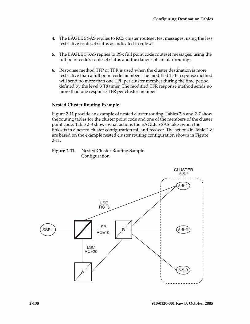
2-138 910-0120-001 Rev B, October 2005
Configuring Destination Tables
4. The EAGLE 5 SAS replies to RCx cluster routeset test messages, using the less restrictive routeset status as indicated in rule #2.
5. The EAGLE 5 SAS replies to RSx full point code routeset messages, using the full point code's routeset status and the danger of circular routing.
6. Response method TFP or TFR is used when the cluster destination is more restrictive than a full point code member. The modified TFP response method will send no more than one TFP per cluster member during the time period defined by the level 3 T8 timer. The modified TFR response method sends no more than one response TFR per cluster member.
Nested Cluster Routing Example
Figure 2-11 provide an example of nested cluster routing. Tables 2-6 and 2-7 show the routing tables for the cluster point code and one of the members of the cluster point code. Table 2-8 shows what actions the EAGLE 5 SAS takes when the linksets in a nested cluster configuration fail and recover. The actions in Table 2-8 are based on the example nested cluster routing configuration shown in Figure 2-11.
Figure 2-11. Nested Cluster Routing Sample Configuration
B
A
LSERC=5
LSCRC=20
LSBRC=10
SSP1
5-5-1
5-5-2
5-5-3
CLUSTER5-5-*
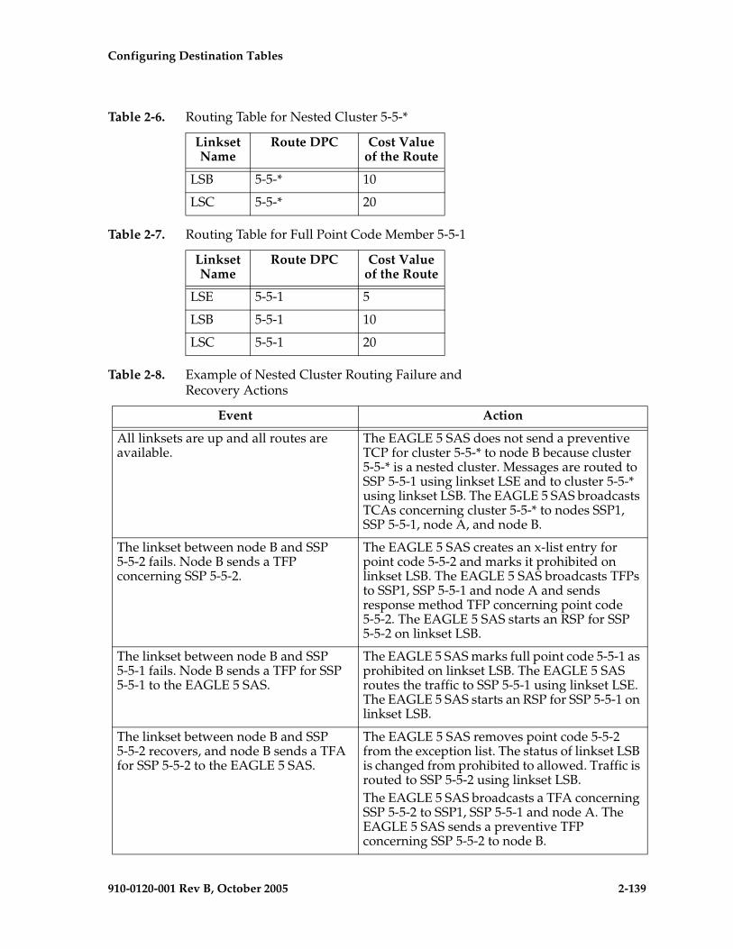
Configuring Destination Tables
910-0120-001 Rev B, October 2005 2-139
Table 2-6. Routing Table for Nested Cluster 5-5-*
Linkset Name
Route DPC Cost Value of the Route
LSB 5-5-* 10
LSC 5-5-* 20
Table 2-7. Routing Table for Full Point Code Member 5-5-1
Linkset Name
Route DPC Cost Value of the Route
LSE 5-5-1 5
LSB 5-5-1 10
LSC 5-5-1 20
Table 2-8. Example of Nested Cluster Routing Failure and Recovery Actions
Event Action
All linksets are up and all routes are available.
The EAGLE 5 SAS does not send a preventive TCP for cluster 5-5-* to node B because cluster 5-5-* is a nested cluster. Messages are routed to SSP 5-5-1 using linkset LSE and to cluster 5-5-* using linkset LSB. The EAGLE 5 SAS broadcasts TCAs concerning cluster 5-5-* to nodes SSP1, SSP 5-5-1, node A, and node B.
The linkset between node B and SSP 5-5-2 fails. Node B sends a TFP concerning SSP 5-5-2.
The EAGLE 5 SAS creates an x-list entry for point code 5-5-2 and marks it prohibited on linkset LSB. The EAGLE 5 SAS broadcasts TFPs to SSP1, SSP 5-5-1 and node A and sends response method TFP concerning point code 5-5-2. The EAGLE 5 SAS starts an RSP for SSP 5-5-2 on linkset LSB.
The linkset between node B and SSP 5-5-1 fails. Node B sends a TFP for SSP 5-5-1 to the EAGLE 5 SAS.
The EAGLE 5 SAS marks full point code 5-5-1 as prohibited on linkset LSB. The EAGLE 5 SAS routes the traffic to SSP 5-5-1 using linkset LSE. The EAGLE 5 SAS starts an RSP for SSP 5-5-1 on linkset LSB.
The linkset between node B and SSP 5-5-2 recovers, and node B sends a TFA for SSP 5-5-2 to the EAGLE 5 SAS.
The EAGLE 5 SAS removes point code 5-5-2 from the exception list. The status of linkset LSB is changed from prohibited to allowed. Traffic is routed to SSP 5-5-2 using linkset LSB.The EAGLE 5 SAS broadcasts a TFA concerning SSP 5-5-2 to SSP1, SSP 5-5-1 and node A. The EAGLE 5 SAS sends a preventive TFP concerning SSP 5-5-2 to node B.
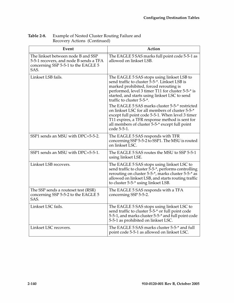
2-140 910-0120-001 Rev B, October 2005
Configuring Destination Tables
The linkset between node B and SSP 5-5-1 recovers, and node B sends a TFA concerning SSP 5-5-1 to the EAGLE 5 SAS.
The EAGLE 5 SAS marks full point code 5-5-1 as allowed on linkset LSB.
Linkset LSB fails. The EAGLE 5 SAS stops using linkset LSB to send traffic to cluster 5-5-*. Linkset LSB is marked prohibited, forced rerouting is performed, level 3 timer T11 for cluster 5-5-* is started, and starts using linkset LSC to send traffic to cluster 5-5-*.The EAGLE 5 SAS marks cluster 5-5-* restricted on linkset LSC for all members of cluster 5-5-* except full point code 5-5-1. When level 3 timer T11 expires, a TFR response method is sent for all members of cluster 5-5-* except full point code 5-5-1.
SSP1 sends an MSU with DPC=5-5-2. The EAGLE 5 SAS responds with TFR concerning SSP 5-5-2 to SSP1. The MSU is routed on linkset LSC.
SSP1 sends an MSU with DPC=5-5-1. The EAGLE 5 SAS routes the MSU to SSP 5-5-1 using linkset LSE.
Linkset LSB recovers. The EAGLE 5 SAS stops using linkset LSC to send traffic to cluster 5-5-*, performs controlling rerouting on cluster 5-5-*, marks cluster 5-5-* as allowed on linkset LSB, and starts routing traffic to cluster 5-5-* using linkset LSB.
The SSP sends a routeset test (RSR) concerning SSP 5-5-2 to the EAGLE 5 SAS.
The EAGLE 5 SAS responds with a TFA concerning SSP 5-5-2.
Linkset LSC fails. The EAGLE 5 SAS stops using linkset LSC to send traffic to cluster 5-5-* or full point code 5-5-1, and marks cluster 5-5-* and full point code 5-5-1 as prohibited on linkset LSC.
Linkset LSC recovers. The EAGLE 5 SAS marks cluster 5-5-* and full point code 5-5-1 as allowed on linkset LSC.
Table 2-8. Example of Nested Cluster Routing Failure and Recovery Actions (Continued)
Event Action

Configuring Destination Tables
910-0120-001 Rev B, October 2005 2-141
Limitations of the Nested Cluster Routing Feature
1. The EAGLE 5 SAS only supports a maximum of 200 nested cluster destinations. This limit does not apply to non-nested clusters (clusters with the ncai parameter set to no).
2. If a cluster is more restricted than a member, the EAGLE 5 SAS broadcasts the status of the least restricted member, and relies on response method for members of the cluster that do not have a full point code entry.
3. The EAGLE 5 SAS does not broadcast preventive TCPs for nested cluster destinations. Because the EAGLE 5 SAS does not send preventive TCPs when it begins routing towards a nested cluster, circular routing can occur. The EAGLE 5 SAS sends response method TFPs if it receives an MSU when there is a danger of circular routing.
Linkset LSE fails. The EAGLE 5 SAS stops using linkset LSE to send traffic to SSP-5-5-1, marks SSP 5-5-1 as prohibited on linkset LSE, performs forced rerouting, starts level 3 timer T11 concerning SSP 5-5-1, sends preventive TFP concerning SSP 5-5-1 to node B, and starts using linkset LSB to send traffic to full point code 5-5-1. The EAGLE 5 SAS marks full point code 5-5-1 as restricted on linkset LSB. When level 3 timer T11 expires, a TFR concerning SSP 5-5-1 is sent to SSP1 and node A.
SSP1 sends an MSU with the DPC 5-5-2. The EAGLE 5 SAS routes the MSU to SSP 5-5-2 using linkset LSB.
SSP1 sends an MSU with the DPC 5-5-1. The EAGLE 5 SAS responds with a TFR concerning SSP 5-5-1 to SSP1. The MSU is routed to SSP 5-5-1 using linkset LSB.
Linkset LSE recovers. The EAGLE 5 SAS stops using linkset LSB to send traffic to SSP 5-5-1, performs controlling rerouting on full point code 5-5-1, marks full point code 5-5-1 as allowed on linkset LSE, and starts routing traffic to full point code 5-5-1 using linkset LSE. The EAGLE 5 SAS broadcasts a TFA for SSP 5-5-1 to SSP1, node A, and node B.
Table 2-8. Example of Nested Cluster Routing Failure and Recovery Actions (Continued)
Event Action
2-142 910-0120-001 Rev B, October 2005
Configuring Destination Tables
Adding a Cluster Point Code
This procedure is used to add a cluster point code for the Cluster Routing and Management Diversity (CRMD) feature, and nested cluster point codes for the nested cluster routing feature to the database, using the ent-dstn command.
To change the attributes of an existing cluster point code, go to the “Changing the Attributes of a Cluster Point Code” procedure on page 2-161.
NOTE: Cluster entries can only be provisioned as ANSI destination point codes. Cluster entries cannot be provisioned for ITU international or ITU national destination point codes. The ANSI alias point code for an ITU international or ITU national destination point code must be a full point code. An ANSI private point code must be a full point code.
To remove a cluster point code from the database, go to the “Removing a Destination Point Code” procedure on page 2-214.
The Cluster Routing and Management Diversity feature must be turned on.
The ent-dstn command uses these parameters:
:dpc/dpca – The destination point code being added to the database.
NOTE: See “Point Code Formats” on page 2-4 for a definition of the point code types that are used on the EAGLE 5 SAS.
NOTE: Alias point codes (aliasi/aliasn/aliasn24) and secondary point codes (spc/spca) cannot be specified for a cluster point code.
:clli – The Common Language Location Identifier assigned to this point code.
:domain – The network in which the destination entity or node exists, X.25 or SS7 .
NOTE: Specifying :domain=ss7 is the only valid entry for cluster destinations.
:bei – Broadcast exception indicator that indicates whether transfer-prohibited (TFP) messages will be broadcast from this node. The bei=yes parameter means TFPs will not be broadcast. The bei=no parameter means TFPs will be broadcast.
:ipgwapc – (ANSI networks only) IP Gateway Adjacent Point Code indicator. Specify ipgwapc=yes to provide SS7 linkset definition compatibility for gateway connections to IP-SCPs. The default is ipgwapc=no.
:elei – For cluster point codes only. Specifies whether or not the EAGLE 5 SAS maintains a dynamic status exception list for each cluster route that may be used to reach the member signaling points making up the cluster. The elei=yes parameter means the EAGLE 5 SAS does not maintain an exception list for the cluster point code specified by the dpc parameter. The elei=no parameter means the EAGLE 5 SAS does maintain an exception list for the cluster point code specified by the dpc parameter. The default value for the elei parameter is no.
Configuring Destination Tables
910-0120-001 Rev B, October 2005 2-143
:ncai – The nested-cluster-allowed indicator specifies whether or not the route to the cluster point code can be different from the route to a point code that is a member of the cluster point code. A point code is a member of a cluster point code if it has the same network identifier (NI) and network cluster (NC) values as the cluster point code. This parameter can be specified only for cluster point codes.
If the ncai parameter value is yes, the cluster point code is a nested cluster point code. Point codes that are members of this cluster point code can be assigned to routesets that are different from the routeset assigned to the cluster point code.
If the ncai parameter value is no, the cluster point code is not a nested cluster point code. Point codes that are members of this cluster point code must be assigned to the same routeset assigned to the cluster point code.
The default value for the ncai parameter is no.
See the “Nested Cluster Routing” section on page 2-135 for more information on the nested cluster routing feature.
To add a cluster point code to the database, the Cluster Routing and Management Diversity feature must be on. The ncai parameter can be specified for the cluster point code only if both the Cluster Routing and Management Diversity and nested cluster routing features are on. This is shown by the entries CRMD = on (for the Cluster Routing and Management Diversity feature) and NCR = on (for the nested cluster routing feature) in the rtrv-feat command output.
The domain of the cluster point code must be SS7 (domain=ss7).
To enter an ANSI point code, an ANSI self ID for the EAGLE 5 SAS must be defined. This can be verified with the rtrv-sid command. The ANSI self ID is shown in the PCA field in the rtrv-sid command output. If no values are shown in the PCA field of the rtrv-sid command output, go to “Changing the Self-Identification of the EAGLE 5 SAS” procedure on page 2-90 to add the ANSI Self ID of the EAGLE 5 SAS.
The actual number of destination point codes that can be configured in the database is set by the mtpdpcq parameter of the chg-stpopts command, and is shown in the MTPDPCQ field in the rtrv-stpopts command output. See step 10 in the procedure that follows.
If the 5000 Routes feature is not on, and 6000, 7000, or 8000 routesets are not enabled, the sum of the mtpdpcq and mtpxlq parameters cannot exceed 2500. The range of values for the mtpdpcq and mtpxlq parameters is 500 to 2000.
If the 5000 Routes feature is on, the sum of the mtpdpcq and mtpxlq parameters cannot exceed 5500. The range of values for the mtpdpcq and mtpxlq parameters is 500 to 5000.
If 6000 routesets are enabled, the sum of the mtpdpcq and mtpxlq parameters cannot exceed 6500. The range of values for the mtpdpcq and mtpxlq parameters is 500 to 6000.

2-144 910-0120-001 Rev B, October 2005
Configuring Destination Tables
If 7000 routesets are enabled, the sum of the mtpdpcq and mtpxlq parameters cannot exceed 7500. The range of values for the mtpdpcq parameter is 500 to 7000. The range of values for the mtpxlq parameter is 500 to 6000.
If 8000 routesets are enabled, the sum of the mtpdpcq and mtpxlq parameters cannot exceed 8500. The range of values for the mtpdpcq parameter is 500 to 8000. The range of values for the mtpxlq parameter is 500 to 6000.
NOTE: For more information on the destination point code quantities, go to the “Changing the DPC Quantity” procedure on page 2-23.
If the ncai parameter value is yes, the EAGLE 5 SAS can have a maximum of 200 nested cluster point codes in the database.
The value of the clli parameter cannot be in the DPC table and cannot match the CLLI of the EAGLE 5 SAS. Verify this by entering the rtrv-dstn and the rtrv-sid commands, shown in steps 3 and 4 of the procedure. If the value of the clli parameter matches any CLLI values in either of these outputs, choose another value for the clli parameter that does not match any CLLIs shown in either of these command outputs.
If the PCTYPE field of the rtrv-sid command output contains the entry ANSI, and the network value of the destination point codes specified by the ent-dstn command, is from 0 to 5, the cluster value of that point code must be from 1 to 255. If the network value of that point code is from 6 to 255, the cluster value of that point code must be from 0 to 255.
To add a cluster point code to the database when the database contains point codes that are members of the cluster, the linkset type used by the routes to the member point codes must be either B, C, or D. For example, you wish to add the cluster point code 004-004-* and the database contains point codes 004-004-001 and 004-004-002. When cluster point code is added, point codes 004-004-001 and 004-004-002 would become members of the cluster point code 004-004-*. If point codes 004-004-001 or 004-004-002 are the destination point codes of routes, and the linkset type of these routes are either A or E, the cluster point code 004-004-* cannot be added to the database. The linkset type of these routes must be changed to either B, C, or D to add cluster point code 004-004-* to the database. To change the linkset type of a linkset, perform the “Changing an SS7 Linkset” procedure on page 3-74.
The examples in this procedure are used to enter the cluster point code 111-011-* and the nested cluster point code 030-045-*.
Canceling the RTRV-DSTN Command
Because the rtrv-dstn command used in this procedure can output information for a long period of time, the rtrv-dstn command can be canceled and the output to the terminal stopped. There are three ways that the rtrv-dstn command can be canceled:
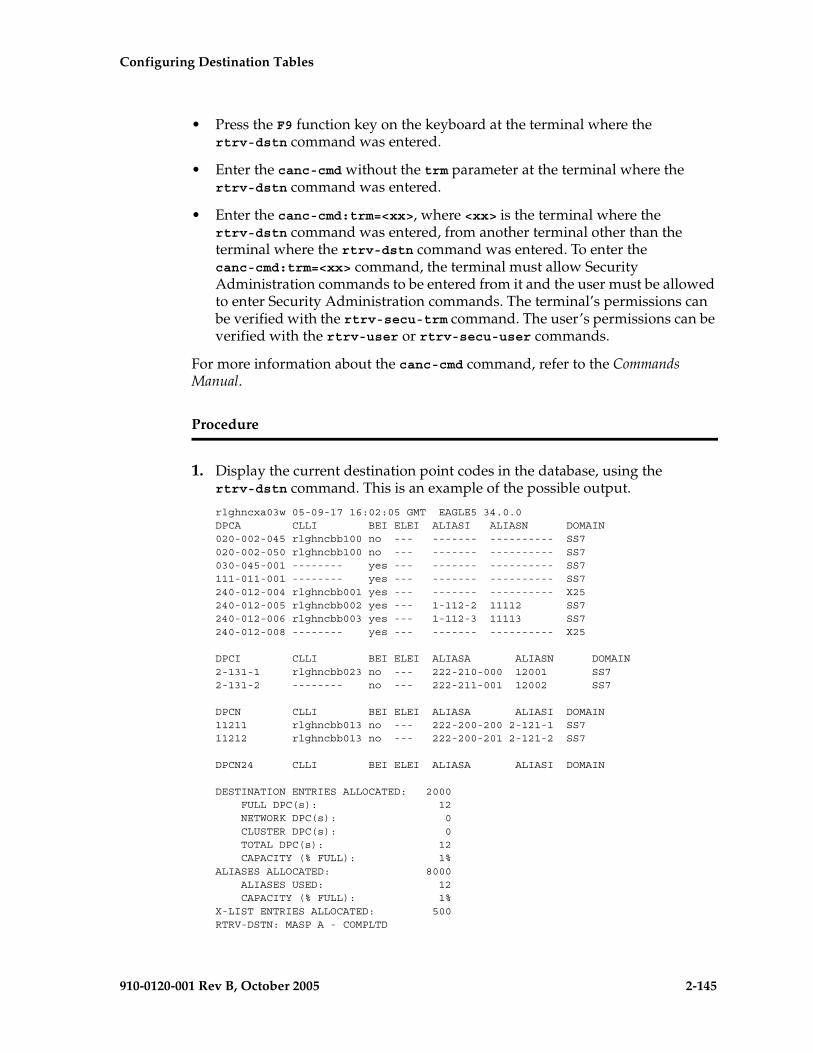
Configuring Destination Tables
910-0120-001 Rev B, October 2005 2-145
• Press the F9 function key on the keyboard at the terminal where the rtrv-dstn command was entered.
• Enter the canc-cmd without the trm parameter at the terminal where the rtrv-dstn command was entered.
• Enter the canc-cmd:trm=<xx>, where <xx> is the terminal where the rtrv-dstn command was entered, from another terminal other than the terminal where the rtrv-dstn command was entered. To enter the canc-cmd:trm=<xx> command, the terminal must allow Security Administration commands to be entered from it and the user must be allowed to enter Security Administration commands. The terminal’s permissions can be verified with the rtrv-secu-trm command. The user’s permissions can be verified with the rtrv-user or rtrv-secu-user commands.
For more information about the canc-cmd command, refer to the Commands Manual.
Procedure
1. Display the current destination point codes in the database, using the rtrv-dstn command. This is an example of the possible output.
rlghncxa03w 05-09-17 16:02:05 GMT EAGLE5 34.0.0DPCA CLLI BEI ELEI ALIASI ALIASN DOMAIN020-002-045 rlghncbb100 no --- ------- ---------- SS7020-002-050 rlghncbb100 no --- ------- ---------- SS7030-045-001 -------- yes --- ------- ---------- SS7111-011-001 -------- yes --- ------- ---------- SS7240-012-004 rlghncbb001 yes --- ------- ---------- X25240-012-005 rlghncbb002 yes --- 1-112-2 11112 SS7240-012-006 rlghncbb003 yes --- 1-112-3 11113 SS7240-012-008 -------- yes --- ------- ---------- X25
DPCI CLLI BEI ELEI ALIASA ALIASN DOMAIN2-131-1 rlghncbb023 no --- 222-210-000 12001 SS72-131-2 -------- no --- 222-211-001 12002 SS7
DPCN CLLI BEI ELEI ALIASA ALIASI DOMAIN11211 rlghncbb013 no --- 222-200-200 2-121-1 SS711212 rlghncbb013 no --- 222-200-201 2-121-2 SS7
DPCN24 CLLI BEI ELEI ALIASA ALIASI DOMAIN
DESTINATION ENTRIES ALLOCATED: 2000 FULL DPC(s): 12 NETWORK DPC(s): 0 CLUSTER DPC(s): 0 TOTAL DPC(s): 12 CAPACITY (% FULL): 1%ALIASES ALLOCATED: 8000 ALIASES USED: 12 CAPACITY (% FULL): 1%X-LIST ENTRIES ALLOCATED: 500RTRV-DSTN: MASP A - COMPLTD

2-146 910-0120-001 Rev B, October 2005
Configuring Destination Tables
If the addition of the cluster point code will not exceed the current DPC capacity shown in the rtrv-dstn output, go to step 2.
If the addition of the cluster point code will exceed the current DPC capacity, and the current capacity is less than 8000 (or 8500 if the DESTINATION ENTRIES ALLOCATED and X-LIST ENTRIES ALLOCATED fields are shown in the rtrv-dstn output), perform the “Changing the DPC Quantity” procedure on page 2-23 to change the DPC quantity. Then go to step 2.
If the addition of the cluster point code will exceed the current DPC capacity, and the current capacity is 8000 (or 8500 if the DESTINATION ENTRIES ALLOCATED and X-LIST ENTRIES ALLOCATED fields are shown in the rtrv-dstn output), perform the “Removing a Destination Point Code” procedure on page 2-214 to remove a DPC. Then go to step 2.
NOTE: If the rtrv-dstn output in step 1 shows any cluster point codes, and nested cluster point codes are not being configured in this procedure, skip this step and go to step 3.
NOTE: If cluster point codes are not shown in the rtrv-dstn output in step 1, but ANSI point codes are shown in step 1, skip this step and go to step 3.
2. Display the self-identification of the EAGLE 5 SAS using the rtrv-sid command. This is an example of the possible output.
rlghncxa03w 05-09-10 11:43:04 GMT EAGLE5 34.0.0PCA PCI PCN CLLI PCTYPE010-020-030 0-123-1 12-0-14-1 rlghncxa03w OTHER
CPCA002-002-002 002-002-003 002-002-004 002-002-005002-002-006 002-002-007 002-002-008 002-002-009004-002-001 004-003-003 050-060-070
CPCI1-001-1 1-001-2 1-001-3 1-001-41-002-1 1-002-2 1-002-3 1-002-42-001-1 7-222-7
CPCN2-0-10-3 2-0-11-0 2-0-11-2 2-0-12-12-2-3-3 2-2-4-0 10-14-10-1
If the PCA field does not contain an entry, perform the “Changing the Self-Identification of the EAGLE 5 SAS” procedure on page 2-90 and add an ANSI point code to the self identification of the EAGLE 5 SAS.

Configuring Destination Tables
910-0120-001 Rev B, October 2005 2-147
NOTE: If the DESTINATION ENTRIES ALLOCATED and X-LIST ENTRIES ALLOCATED fields are shown in the rtrv-dstn output in step 1, and nested cluster point codes are not being configured in this procedure, skip this step and steps 4 and 5, and go to step 6.
3. Verify that the Cluster Routing and Management Diversity feature is turned on, by entering the rtrv-feat command. If nested cluster point codes are to be configured in the database, the nested cluster routing feature must be turned on. If the Cluster Routing and Management Diversity feature is turned on, the CRMD field should be set to on. If the nested cluster routing feature is turned on, the NCR field should be set to on. In this example, both features are off.
NOTE: The rtrv-feat command output contains other fields that are not used by this procedure. If you wish to see all the fields displayed by the rtrv-feat command, see the rtrv-feat command description in the Commands Manual.
NOTE: If the Cluster Routing and Management Diversity feature is on, shown by the CRMD = on entry in the rtrv-feat command output in step 3, skip step 4 and go to step 5.
4. Turn the Cluster Routing and Management Diversity feature on by entering this command.
chg-feat:crmd=on
NOTE: Once the Cluster Routing and Management Diversity feature is turned on with the chg-feat command, it cannot be turned off.
The Cluster Routing and Management Diversity feature must be purchased before you turn this feature on with the chg-feat command. If you are not sure if you have purchased the Cluster Routing and Management Diversity feature, contact your Tekelec Sales Representative or Account Representative.
When this command has successfully completed, this message should appear.
rlghncxa03w 05-09-10 11:43:04 GMT EAGLE5 34.0.0CHG-FEAT: MASP A - COMPLTD
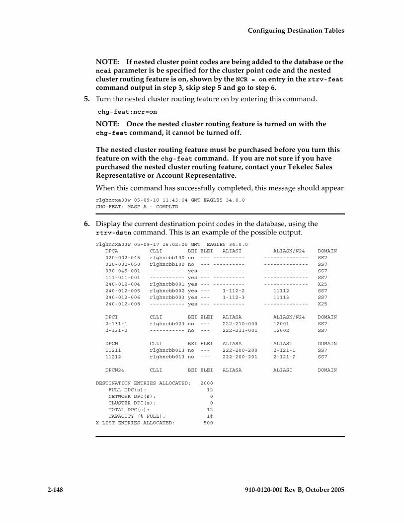
2-148 910-0120-001 Rev B, October 2005
Configuring Destination Tables
NOTE: If nested cluster point codes are being added to the database or the ncai parameter is be specified for the cluster point code and the nested cluster routing feature is on, shown by the NCR = on entry in the rtrv-feat command output in step 3, skip step 5 and go to step 6.
5. Turn the nested cluster routing feature on by entering this command.
chg-feat:ncr=on
NOTE: Once the nested cluster routing feature is turned on with the chg-feat command, it cannot be turned off.
The nested cluster routing feature must be purchased before you turn this feature on with the chg-feat command. If you are not sure if you have purchased the nested cluster routing feature, contact your Tekelec Sales Representative or Account Representative.
When this command has successfully completed, this message should appear.
rlghncxa03w 05-09-10 11:43:04 GMT EAGLE5 34.0.0CHG-FEAT: MASP A - COMPLTD
6. Display the current destination point codes in the database, using the rtrv-dstn command. This is an example of the possible output.
rlghncxa03w 05-09-17 16:02:05 GMT EAGLE5 34.0.0 DPCA CLLI BEI ELEI ALIASI ALIASN/N24 DOMAIN 020-002-045 rlghncbb100 no --- ---------- -------------- SS7 020-002-050 rlghncbb100 no --- ---------- -------------- SS7 030-045-001 ----------- yes --- ---------- -------------- SS7 111-011-001 ----------- yes --- ---------- -------------- SS7 240-012-004 rlghncbb001 yes --- ---------- -------------- X25 240-012-005 rlghncbb002 yes --- 1-112-2 11112 SS7 240-012-006 rlghncbb003 yes --- 1-112-3 11113 SS7 240-012-008 ----------- yes --- ---------- -------------- X25
DPCI CLLI BEI ELEI ALIASA ALIASN/N24 DOMAIN 2-131-1 rlghncbb023 no --- 222-210-000 12001 SS7 2-131-2 ----------- no --- 222-211-001 12002 SS7
DPCN CLLI BEI ELEI ALIASA ALIASI DOMAIN 11211 rlghncbb013 no --- 222-200-200 2-121-1 SS7 11212 rlghncbb013 no --- 222-200-201 2-121-2 SS7
DPCN24 CLLI BEI ELEI ALIASA ALIASI DOMAIN
DESTINATION ENTRIES ALLOCATED: 2000 FULL DPC(s): 12 NETWORK DPC(s): 0 CLUSTER DPC(s): 0 TOTAL DPC(s): 12 CAPACITY (% FULL): 1%X-LIST ENTRIES ALLOCATED: 500

Configuring Destination Tables
910-0120-001 Rev B, October 2005 2-149
NOTE: If the rtrv-dstn output does not show any DPCs that are members of the cluster point code being added in this procedure, skip steps 5 through 6, and go to step 7.
7. The cluster point code cannot be added to the database if the database contains member point codes assigned to routes that are assigned to linksets whose linkset type is either A or E.
Enter the rtrv-rte command with one of the DPCs that is a member of the cluster point code being added in this procedure. For this example, enter these commands.
rtrv-rte:dpca=111-011-001
This is an example of the possible output.
rlghncxa03w 05-09-17 15:35:05 GMT EAGLE5 34.0.0 DPCA ALIASI ALIASN/N24 LSN RC APCA 111-011-001 ------- ----------- lsn2 10 111-011-001 CLLI=-----------
rtrv-rte:dpca=030-045-001
This is an example of the possible output.
rlghncxa03w 05-09-17 15:35:05 GMT EAGLE5 34.0.0 DPCA ALIASI ALIASN/N24 LSN RC APCA 030-045-001 ------- ----------- lsn3 10 030-045-001 CLLI=-----------
If the DPC specified in this step is the DPC of a route, go to step 6.
If the DPC specified in this step is not the DPC of a route, repeat this step for other DPCs, shown in the rtrv-dstn output, that are members of the cluster point code being added in this procedure.
If all the DPCs that are members of the cluster point code being added have been displayed, and none of these DPCs are DPCs of routes, skip step 6 and go to step 7.
8. Enter the rtrv-ls command with the linkset name shown in the rtrv-rte output in step 5. The linkset name is shown in the LSN column of the rtrv-rte output. For this example, enter these commands.
rtrv-ls:lsn=lsn2
This is an example of the possible output.
rlghncxa03w 05-09-17 15:35:05 GMT EAGLE5 34.0.0
L3T SLT GWS GWS GWSLSN APCA (SS7) SCRN SET SET BEI LST LNKS ACT MES DIS SLSCI NISlsn2 111-011-001 none 1 1 no B 2 off off off no off
CLLI TFATCABMLQ MTPRSE ASL8 IPGWAPC ----------- 1 --- no no
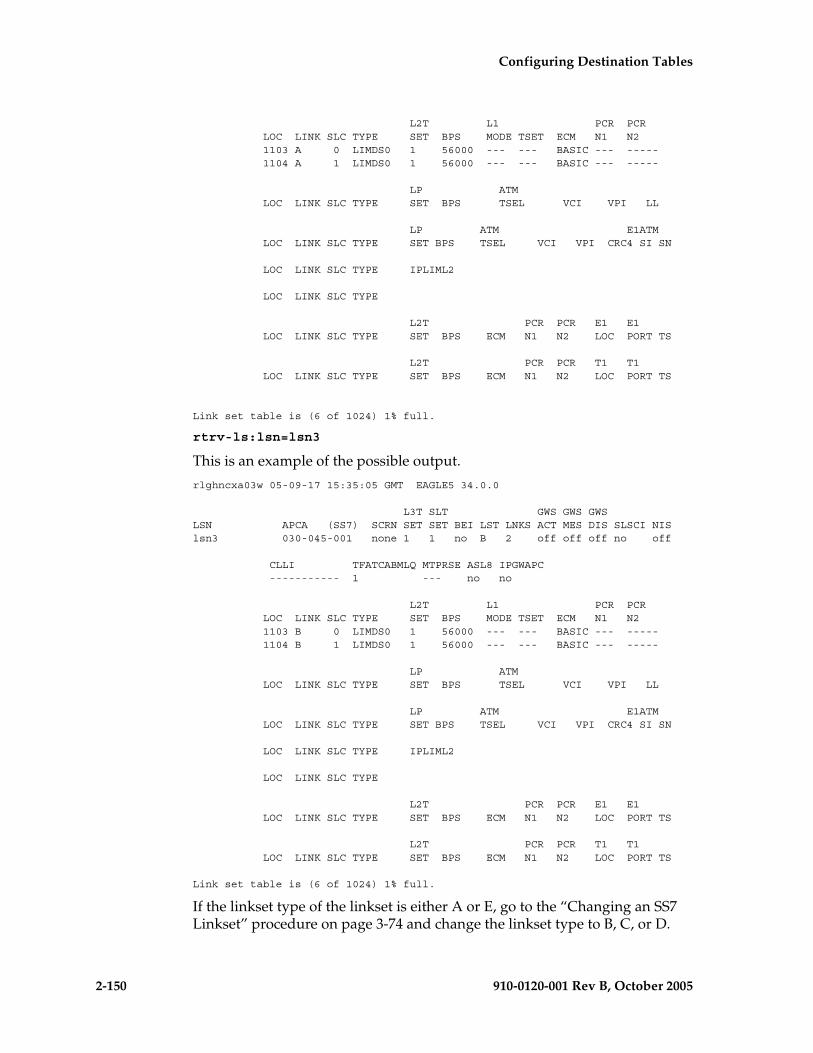
2-150 910-0120-001 Rev B, October 2005
Configuring Destination Tables
L2T L1 PCR PCR LOC LINK SLC TYPE SET BPS MODE TSET ECM N1 N2 1103 A 0 LIMDS0 1 56000 --- --- BASIC --- ----- 1104 A 1 LIMDS0 1 56000 --- --- BASIC --- -----
LP ATM LOC LINK SLC TYPE SET BPS TSEL VCI VPI LL
LP ATM E1ATM LOC LINK SLC TYPE SET BPS TSEL VCI VPI CRC4 SI SN
LOC LINK SLC TYPE IPLIML2
LOC LINK SLC TYPE
L2T PCR PCR E1 E1 LOC LINK SLC TYPE SET BPS ECM N1 N2 LOC PORT TS
L2T PCR PCR T1 T1 LOC LINK SLC TYPE SET BPS ECM N1 N2 LOC PORT TS
Link set table is (6 of 1024) 1% full.
rtrv-ls:lsn=lsn3
This is an example of the possible output.
rlghncxa03w 05-09-17 15:35:05 GMT EAGLE5 34.0.0
L3T SLT GWS GWS GWSLSN APCA (SS7) SCRN SET SET BEI LST LNKS ACT MES DIS SLSCI NISlsn3 030-045-001 none 1 1 no B 2 off off off no off
CLLI TFATCABMLQ MTPRSE ASL8 IPGWAPC ----------- 1 --- no no
L2T L1 PCR PCR LOC LINK SLC TYPE SET BPS MODE TSET ECM N1 N2 1103 B 0 LIMDS0 1 56000 --- --- BASIC --- ----- 1104 B 1 LIMDS0 1 56000 --- --- BASIC --- -----
LP ATM LOC LINK SLC TYPE SET BPS TSEL VCI VPI LL
LP ATM E1ATM LOC LINK SLC TYPE SET BPS TSEL VCI VPI CRC4 SI SN
LOC LINK SLC TYPE IPLIML2
LOC LINK SLC TYPE
L2T PCR PCR E1 E1 LOC LINK SLC TYPE SET BPS ECM N1 N2 LOC PORT TS
L2T PCR PCR T1 T1 LOC LINK SLC TYPE SET BPS ECM N1 N2 LOC PORT TS
Link set table is (6 of 1024) 1% full.
If the linkset type of the linkset is either A or E, go to the “Changing an SS7 Linkset” procedure on page 3-74 and change the linkset type to B, C, or D.
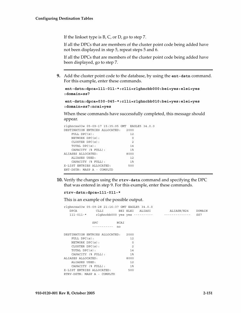
Configuring Destination Tables
910-0120-001 Rev B, October 2005 2-151
If the linkset type is B, C, or D, go to step 7.
If all the DPCs that are members of the cluster point code being added have not been displayed in step 5, repeat steps 5 and 6.
If all the DPCs that are members of the cluster point code being added have been displayed, go to step 7.
9. Add the cluster point code to the database, by using the ent-dstn command. For this example, enter these commands.
ent-dstn:dpca=111-011-*:clli=rlghncbb000:bei=yes:elei=yes:domain=ss7
ent-dstn:dpca=030-045-*:clli=rlghncbb010:bei=yes:elei=yes:domain=ss7:ncai=yes
When these commands have successfully completed, this message should appear.
rlghncxa03w 05-09-17 15:35:05 GMT EAGLE5 34.0.0DESTINATION ENTRIES ALLOCATED: 2000 FULL DPC(s): 12 NETWORK DPC(s): 0 CLUSTER DPC(s): 2 TOTAL DPC(s): 14 CAPACITY (% FULL): 1%ALIASES ALLOCATED: 8000 ALIASES USED: 12 CAPACITY (% FULL): 1%X-LIST ENTRIES ALLOCATED: 500ENT-DSTN: MASP A - COMPLTD
10. Verify the changes using the rtrv-dstn command and specifying the DPC that was entered in step 9. For this example, enter these commands.
rtrv-dstn:dpca=111-011-*
This is an example of the possible output.
rlghncxa03w 05-09-28 21:16:37 GMT EAGLE5 34.0.0 DPCA CLLI BEI ELEI ALIASI ALIASN/N24 DOMAIN 111-011-* rlghncbb000 yes yes ---------- -------------- SS7
SPC NCAI ----------- no
DESTINATION ENTRIES ALLOCATED: 2000 FULL DPC(s): 12 NETWORK DPC(s): 0 CLUSTER DPC(s): 2 TOTAL DPC(s): 14 CAPACITY (% FULL): 1%ALIASES ALLOCATED: 8000 ALIASES USED: 12 CAPACITY (% FULL): 1%X-LIST ENTRIES ALLOCATED: 500RTRV-DSTN: MASP A - COMPLTD

2-152 910-0120-001 Rev B, October 2005
Configuring Destination Tables
rtrv-dstn:dpca=030-045-*
This is an example of the possible output.
rlghncxa03w 05-09-28 21:16:37 GMT EAGLE5 34.0.0 DPCA CLLI BEI ELEI ALIASI ALIASN/N24 DOMAIN 030-045-* rlghncbb010 yes yes ---------- -------------- SS7
SPC NCAI ----------- yes
DESTINATION ENTRIES ALLOCATED: 2000 FULL DPC(s): 12 NETWORK DPC(s): 0 CLUSTER DPC(s): 2 TOTAL DPC(s): 14 CAPACITY (% FULL): 1%ALIASES ALLOCATED: 8000 ALIASES USED: 12 CAPACITY (% FULL): 1%X-LIST ENTRIES ALLOCATED: 500RTRV-DSTN: MASP A - COMPLTD
NOTE: If you do not wish to change the exception list parameters for the Cluster Routing and Management Diversity feature, skip steps 11, 12, and 13, and go to step 14.
11. The parameters for the exception list for the Cluster Routing and Management Diversity feature can be changed from the default settings by using the chg-stpopts command. The parameters of the chg-stpopts command that control the exception point-code list are:
mtpxlq = the maximum number of entries the exception list (x-list) can contain
mtpxlet = the maximum amount of time the EAGLE 5 SAS will maintain an unreferenced exception list (x-list) entry, expressed in the format hhmm, where hh is the number of hours, and mm is the number of minutes
mtpxlot = the exception list (x-list) occupancy threshold (in terms of percentage of space available). If this threshold is exceeded, the EAGLE 5 SAS raises a minor alarm.
mtpdpcq = the maximum number of destination point codes that can be configured on the EAGLE 5 SAS
NOTE: The sum of the MTPDPCQ and MTPXLQ value’s cannot exceed one of these totals depending on the features that are enabled or turned on:
• 2500 – if the 5000 Routes feature is not on, and 6000, 7000, or 8000 routesets are not enabled. The range of values for the mtpdpcq and mtpxlq parameters is 500 to 2000.
• 5500 – if the 5000 Routes feature is on, but 6000, 7000, or 8000 routesets are not enabled. The range of values for the mtpdpcq and mtpxlq parameters is 500 to 5000.
• 6500 – if 6000 routesets are enabled. The range of values for the mtpdpcq and mtpxlq parameters is 500 to 6000.

Configuring Destination Tables
910-0120-001 Rev B, October 2005 2-153
• 7500 – if 7000 routesets are enabled. The range of values for the mtpdpcq parameter is 500 to 7000. The range of values for the mtpxlq parameter is 500 to 6000.
• 8500 – if 8000 routesets are enabled. The range of values for the mtpdpcq parameter is 500 to 8000. The range of values for the mtpxlq parameter is 500 to 6000.
Display the existing values for the exception list parameters, by entering the rtrv-stpopts command. This is an example of the possible output.
rlghncxa03w 05-09-17 16:02:05 GMT EAGLE5 34.0.0STP OPTIONS-----------------------MTPXLQ 500MTPXLET 0100MTPXLOT 90%MTPDPCQ 2000
NOTE: The rtrv-stpopts command output contains other fields that are not used by this procedure. If you wish to see all the fields displayed by the rtrv-stpopts command, see the rtrv-stpopts command description in the Commands Manual.
NOTE: If the Cluster Routing and Management Diversity was turned on in this procedure, the MTPXLQ, MTPXLET, and MTPXLOT parameters are shown with these default values:
• MTPXLQ – 500
• MTPXLET – 0100
• MTPXLOT – 90%
The MTPDPCQ value is not changed when the Cluster Routing and Management Diversity is turned on.
NOTE: If you do not wish to change the DPC quantity, or the exception list parameters for the Cluster Routing and Management Diversity feature, skip steps 12 and 13, and go to step 14.
12. If you wish to change the exception list parameters or the mtpdpcq value, enter the chg-stpopts command.
NOTE: If the DPC quantity or the exception list quantity is being changed in this step, both the mtpdpcq and mtpxlq parameters do have to be specified in this step unless the resulting sum of the mtpdpcq and mtpxlq parameters would exceed the totals shown in step 10.
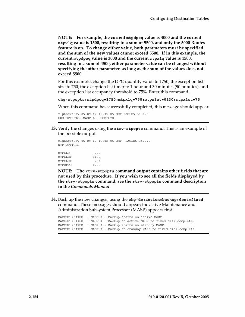
2-154 910-0120-001 Rev B, October 2005
Configuring Destination Tables
NOTE: For example, the current mtpdpcq value is 4000 and the current mtpxlq value is 1500, resulting in a sum of 5500, and only the 5000 Routes feature is on. To change either value, both parameters must be specified and the sum of the new values cannot exceed 5500. If in this example, the current mtpdpcq value is 3000 and the current mtpxlq value is 1500, resulting in a sum of 4500, either parameter value can be changed without specifying the other parameter as long as the sum of the values does not exceed 5500.
For this example, change the DPC quantity value to 1750, the exception list size to 750, the exception list timer to 1 hour and 30 minutes (90 minutes), and the exception list occupancy threshold to 75%. Enter this command.
chg-stpopts:mtpdpcq=1750:mtpxlq=750:mtpxlet=0130:mtpxlot=75
When this command has successfully completed, this message should appear.
rlghncxa03w 05-09-17 15:35:05 GMT EAGLE5 34.0.0CHG-STPOPTS: MASP A - COMPLTD
13. Verify the changes using the rtrv-stpopts command. This is an example of the possible output.
rlghncxa03w 05-09-17 16:02:05 GMT EAGLE5 34.0.0STP OPTIONS-----------------------MTPXLQ 750MTPXLET 0130MTPXLOT 75%MTPDPCQ 1750
NOTE: The rtrv-stpopts command output contains other fields that are not used by this procedure. If you wish to see all the fields displayed by the rtrv-stpopts command, see the rtrv-stpopts command description in the Commands Manual.
14. Back up the new changes, using the chg-db:action=backup:dest=fixed command. These messages should appear; the active Maintenance and Administration Subsystem Processor (MASP) appears first.
BACKUP (FIXED) : MASP A - Backup starts on active MASP.BACKUP (FIXED) : MASP A - Backup on active MASP to fixed disk complete.BACKUP (FIXED) : MASP A - Backup starts on standby MASP.BACKUP (FIXED) : MASP A - Backup on standby MASP to fixed disk complete.

Configuring Destination Tables
910-0120-001 Rev B, October 2005 2-155
Flowchart 2-8. Adding a Cluster Point Code (Sheet 1 of 6)
NOTE: Before executing this procedure, make sure you have purchased the Cluster Routing and Management Diversity feature and the nested cluster routing feature. If you are not sure if you have purchased the Cluster Routing and Management Diversity feature and the nested cluster routing feature, contact your Tekelec Sales Representative or Account Representative.

2-156 910-0120-001 Rev B, October 2005
Configuring Destination Tables
Flowchart 2-8. Adding a Cluster Point Code (Sheet 2 of 6)
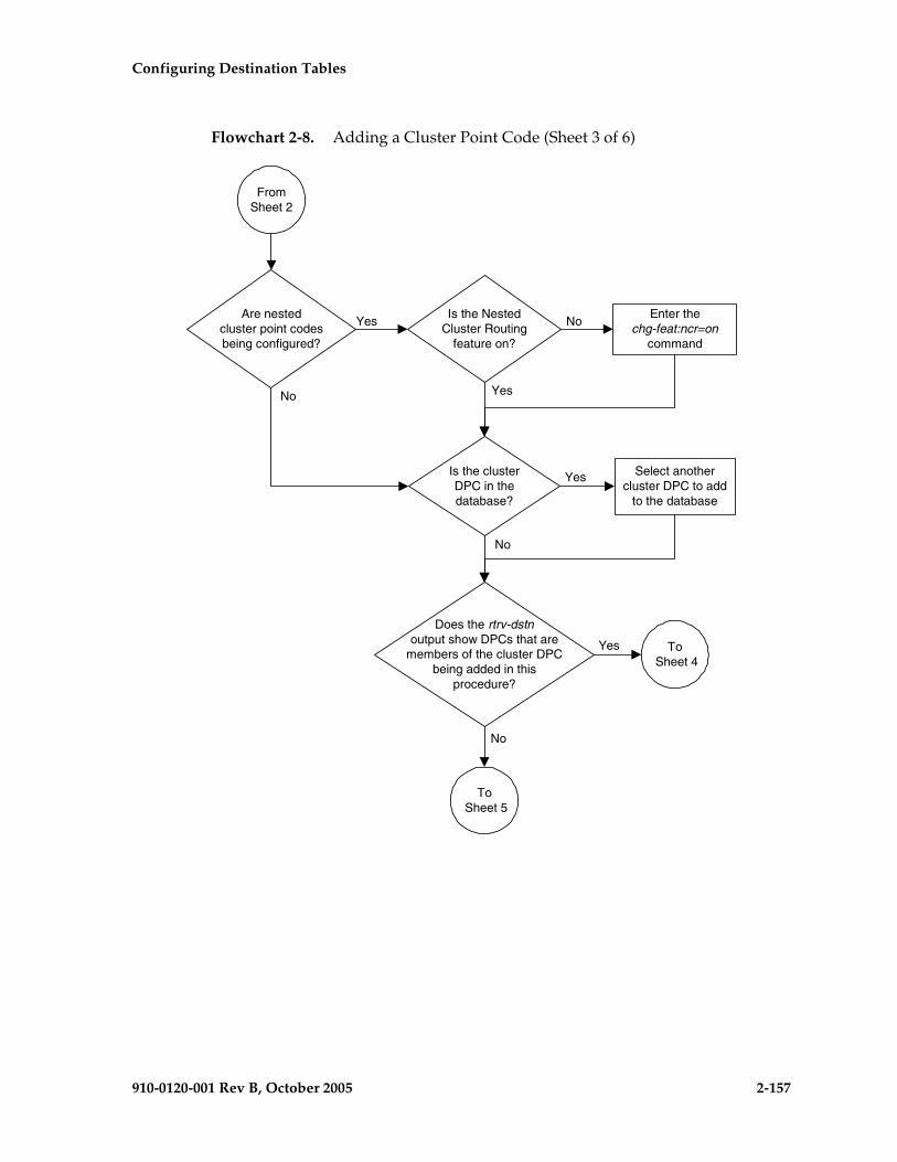
Configuring Destination Tables
910-0120-001 Rev B, October 2005 2-157
Flowchart 2-8. Adding a Cluster Point Code (Sheet 3 of 6)
To Sheet 5
No
FromSheet 2
Is the clusterDPC in thedatabase?
Yes Select anothercluster DPC to add
to the database
Does the rtrv-dstnoutput show DPCs that are
members of the cluster DPCbeing added in this
procedure?
Yes
No
To Sheet 4
Are nestedcluster point codesbeing configured?
Is the NestedCluster Routing
feature on?
Enter thechg-feat:ncr=on
command
Yes
YesNo
No

2-158 910-0120-001 Rev B, October 2005
Configuring Destination Tables
Flowchart 2-8. Adding a Cluster Point Code (Sheet 4 of 6)
FromSheet 3
Enter thertrv-rte:dpca=<point code
from rtrv-dstn that is amember of the cluster point
code being added>command
Enter thertrv-ls:lsn=<linkset name
shown in the rtrv-rteoutput> command
Is the DPC aDPC of a route?
Is the linkset typeA or E?
Go to the “Changing anSS7 Linkset” procedure inthis manual and changethe linkset type to either
B, C, or D
Have all the DPCs thatare members of the cluster DPC
being added in this procedurebeen displayed?
To Sheet 5
Yes
Yes
Yes
No
No
No

Configuring Destination Tables
910-0120-001 Rev B, October 2005 2-159
Flowchart 2-8. Adding a Cluster Point Code (Sheet 5 of 6)

2-160 910-0120-001 Rev B, October 2005
Configuring Destination Tables
Flowchart 2-8. Adding a Cluster Point Code (Sheet 6 of 6)
FromSheet 5
Enter thertrv-dstn:dpca=<xxx-xxx-*>
command where <xxx-xxx-*> isthe cluster point code added to
the database on Sheet 5
Enter thechg-db:action=backup:dest=fixed
command
Do you wish tochange the exception list
parameters?
Yes
No
Enter thechg-stpopts command with atleast one of these parameters:
mtplxq =<See Notes>mtpxlet=<0020 - 2400>
mtpxlot=<0 - 100>mtpdpcq=<See Notes>
Enter thertrv-stpopts command
Enter thertrv-stpopts command
Notes:
1. The sum of the values for the mtpdpcq and mtpxlq parameters cannot exceed thesevalues, depending which routeset quantity has been enabled with the enable-ctrl-featcommand, or turned on with the chg-feat command:
! 5000 routes not turned on, 6000, 7000, or 8000 routesets not enabled - 2500. The rangeof values for the mtpdpcq and mtpxlq parameters is 500 to 2000.
! 5000 routes turned on, 6000, 7000, or 8000 routesets not enabled - 5500. The range ofvalues for the mtpdpcq and mtpxlq parameters is 500 to 5000.
! 6000 routesets enabled - 6500. The range of values for the mtpdpcq and mtpxlqparameters is 500 to 6000.
! 7000 routesets enabled - 7500. The range of values for the mtpdpcq parameter is 500 to7000. The range of values for the mtpxlq parameter is 500 to 6000.
! 8000 routesets enabled - 8500. The range of values for the mtpdpcq parameter is 500 to8000. The range of values for the mtpxlq parameter is 500 to 6000.
2. If the DPC quantity or the exception list quantity is being changed in this step, both themtpdpcq and mtpxlq parameters do have to be specified in this step unless the resultingsum of the mtpdpcq and mtpxlq parameters would exceed the totals shown in Note 1.
For example, the current mtpdpcq value is 4000 and the current mtpxlq value is 1500,resulting in a sum of 5500, and only the 5000 Routes feature is on. To increase eithervalue, both parameters must be specified and the sum of the new values cannot exceed5500. If either value is being decreased, the other parameter can be specified as long asthe sum of the values does not exceed 5500.
If in this example, the current mtpdpcq value is 3000 and the current mtpxlq value is 1500,resulting in a sum of 4500, either parameter value can be changed without specifying theother parameter as long as the sum of the values does not exceed 5500.

Configuring Destination Tables
910-0120-001 Rev B, October 2005 2-161
Changing the Attributes of a Cluster Point Code
This procedure is used to change the attributes of a cluster point code in the database, using the chg-dstn command.
NOTE: Cluster entries can be provisioned only as ANSI destination point codes. Cluster entries cannot be provisioned for ITU international or ITU national destination point codes. The ANSI alias point code for an ITU international or ITU national destination point code must be a full point code. An ANSI private point code must be a full point code.
To add a new cluster point code to the database, go to the “Adding a Cluster Point Code” procedure on page 2-142.
To remove a cluster point code from the database, go to the “Removing a Destination Point Code” procedure on page 2-214.
The cluster point code to be changed must be in the database.
The chg-dstn command uses these parameters:
:dpc/dpca – The destination point code in the database being changed
NOTE: See “Point Code Formats” on page 2-4 for a definition of the point code types that are used on the EAGLE 5 SAS.
NOTE: Alias point codes (aliasi/aliasn/aliasn24) and secondary point codes (spc/spca) cannot be specified for a cluster point code.
:clli – The Common Language Location Identifier assigned to this point code
:domain – The network in which the destination entity or node exists X.25 or SS7
NOTE: Specifying :domain=x25 is valid only for ANSI destinations, but cannot be specified for cluster point codes.
:bei – Broadcast exception indicator that indicates whether transfer-prohibited (TFP) messages will be broadcast from this node. The bei=yes parameter means TFPs will not be broadcast. The bei=no parameter means TFPs will be broadcast.
:ipgwapc – (ANSI networks only) IP Gateway Adjacent Point Code indicator. Specify ipgwapc=yes to provide SS7 linkset definition compatibility for gateway connections to IP-SCPs. The default is ipgwapc=no.
:elei – For cluster point codes only. Specifies whether or not the EAGLE 5 SAS maintains a dynamic status exception list for each cluster route that may be used to reach the member signaling points making up the cluster. The elei=yes parameter means the EAGLE 5 SAS does not maintain an exception list for the cluster point code specified by the dpc parameter. The elei=no parameter means the EAGLE 5 SAS does maintain an exception list for the cluster point code specified by the dpc parameter.
2-162 910-0120-001 Rev B, October 2005
Configuring Destination Tables
:ncai – The nested-cluster-allowed indicator specifies whether or not the route to the cluster point code can be different from the route to a point code that is a member of the cluster point code. A point code is a member of a cluster point code if it has the same network identifier (NI) and network cluster (NC) values as the cluster point code. This parameter can be specified only for cluster point codes.
If the ncai parameter value is yes, the cluster point code is a nested cluster point code. Point codes that are members of this cluster point code can be assigned to routesets that are different from the routeset assigned to the cluster point code.
If the ncai parameter value is no, the cluster point code is not a nested cluster point code. Point codes that are members of this cluster point code must be assigned to the same routeset assigned to the cluster point code.
See the “Nested Cluster Routing” section on page 2-135 for more information on the nested cluster routing feature.
The value of the clli parameter cannot be in the DPC table and cannot match the CLLI of the EAGLE 5 SAS. Verify this by entering the rtrv-dstn and the rtrv-sid commands, shown in steps 1 and 3. If the value of the clli parameter matches any CLLI values in either of these outputs, choose another value for the clli parameter that does not match any CLLIs shown in either of these command outputs.
If a nested cluster point code is changed to a non-nested cluster point code (the value of the ncai parameter is changed from yes to no), any point codes that are members of this point code must be assigned to the same routeset as the cluster point code.
If an X.25 destination point code is a member of a cluster, the value of the bei parameter for the X.25 destination point code is not changed to the value of the bei parameter of the cluster, but the value of the bei parameter of the cluster determines the behavior of the X.25 destination point code as long as the cluster remains in the DPC table. If this cluster is removed from the DPC table, the X.25 destination behaves as it is configured with the ent-dstn command. For example, if the X.25 destination point code, 002-002-002, is a member of the cluster 002-002-*, the bei parameter of the cluster is set to yes, and the bei parameter of the X.25 destination point code is set to no, the X.25 destination point code behaves as if the bei parameter is set to yes. If the cluster 002-002-* is removed from the database, the bei parameter of the X.25 destination point code is set to no and the X.25 destination point code broadcasts TFP and TFA messages to adjacent nodes.
If you intend to use this X.25 destination point code with an X.25 route that has the lc2nm parameter set to yes, make sure that the bei parameter of the cluster containing the X.25 destination point code is set to no. Verify the value of the bei parameter of the cluster with the rtrv-dstn command. To change the existing value the bei parameter, specify the bei parameter with the appropriate value (yes or no) with the chg-dstn command in this procedure. If the bei parameter

Configuring Destination Tables
910-0120-001 Rev B, October 2005 2-163
is not specified with the chg-dstn command, the value of the bei parameter is not changed.
The elei (exception list exclusion indicator) parameter can be specified only for a cluster destination point code. Cluster destination point codes and the elei parameter can be specified only if the Cluster Routing and Management Diversity feature is turned on. Verify this with the rtrv-feat command. If the Cluster Routing and Management Diversity feature is turned on, the CRMD field should be set to on. If the Cluster Routing and Management Diversity feature is not turned on, enter the chg-feat:crmd=on command. For more information on the Cluster Routing and Management Diversity feature, go to the “Cluster Routing and Management Diversity (CRMD)” section on page 2-119.
The ncai parameter can be specified only if the Nested Cluster Routing feature is on. This can be verified with the entry NCR = on in the rtrv-feat command output. If the nested cluster routing feature is not turned on, enter the chg-feat:ncr=on command. For more information on the nested cluster routing feature, go to the “Nested Cluster Routing” section on page 2-135.
NOTE: Once the Cluster Routing and Management Diversity and nested cluster routing features are turned on with the chg-feat command, they cannot be turned off.
The Cluster Routing and Management Diversity and nested cluster routing features must be purchased before you turn these features on with the chg-feat command. If you are not sure if you have purchased the Cluster Routing and Management Diversity and nested cluster routing features, contact your Tekelec Sales Representative or Account Representative.
The examples in this procedure are used to change the attributes of the cluster point code 030-003-*.
Canceling the RTRV-DSTN and RTRV-RTE Commands
Because the rtrv-dstn and rtrv-rte commands used in this procedure can output information for a long period of time, the rtrv-dstn and rtrv-rte commands can be canceled and the output to the terminal stopped. There are three ways that the rtrv-dstn and rtrv-rte commands can be canceled:
• Press the F9 function key on the keyboard at the terminal where the rtrv-dstn or rtrv-rte command was entered.
• Enter the canc-cmd without the trm parameter at the terminal where the rtrv-dstn or rtrv-rte command was entered.
• Enter the canc-cmd:trm=<xx>, where <xx> is the terminal where the rtrv-dstn or rtrv-rte command was entered, from another terminal other than the terminal where the rtrv-dstn or rtrv-rte command was entered. To enter the canc-cmd:trm=<xx> command, the terminal must allow Security Administration commands to be entered from it and the user must be allowed to enter Security Administration commands. The terminal’s permissions can
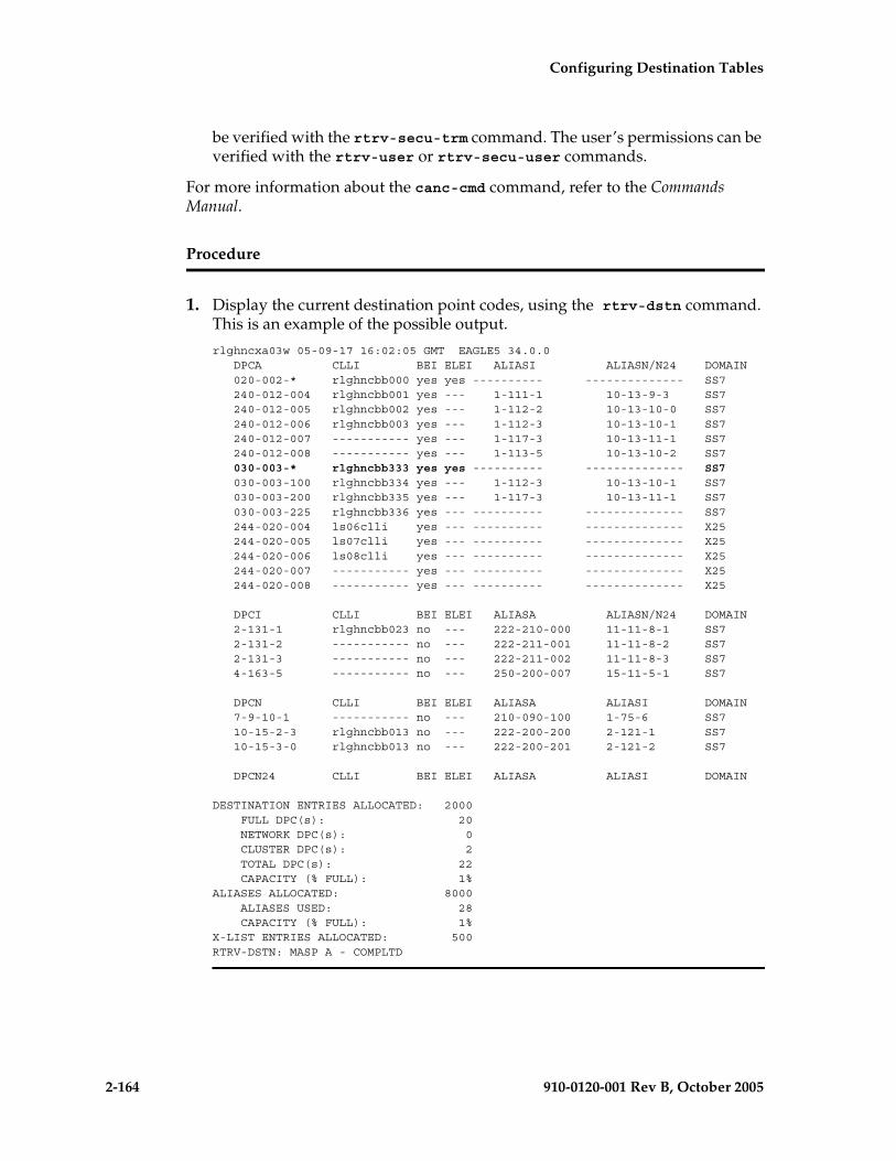
2-164 910-0120-001 Rev B, October 2005
Configuring Destination Tables
be verified with the rtrv-secu-trm command. The user’s permissions can be verified with the rtrv-user or rtrv-secu-user commands.
For more information about the canc-cmd command, refer to the Commands Manual.
Procedure
1. Display the current destination point codes, using the rtrv-dstn command. This is an example of the possible output.
rlghncxa03w 05-09-17 16:02:05 GMT EAGLE5 34.0.0 DPCA CLLI BEI ELEI ALIASI ALIASN/N24 DOMAIN 020-002-* rlghncbb000 yes yes ---------- -------------- SS7 240-012-004 rlghncbb001 yes --- 1-111-1 10-13-9-3 SS7 240-012-005 rlghncbb002 yes --- 1-112-2 10-13-10-0 SS7 240-012-006 rlghncbb003 yes --- 1-112-3 10-13-10-1 SS7 240-012-007 ----------- yes --- 1-117-3 10-13-11-1 SS7 240-012-008 ----------- yes --- 1-113-5 10-13-10-2 SS7 030-003-* rlghncbb333 yes yes ---------- -------------- SS7 030-003-100 rlghncbb334 yes --- 1-112-3 10-13-10-1 SS7 030-003-200 rlghncbb335 yes --- 1-117-3 10-13-11-1 SS7 030-003-225 rlghncbb336 yes --- ---------- -------------- SS7 244-020-004 ls06clli yes --- ---------- -------------- X25 244-020-005 ls07clli yes --- ---------- -------------- X25 244-020-006 ls08clli yes --- ---------- -------------- X25 244-020-007 ----------- yes --- ---------- -------------- X25 244-020-008 ----------- yes --- ---------- -------------- X25
DPCI CLLI BEI ELEI ALIASA ALIASN/N24 DOMAIN 2-131-1 rlghncbb023 no --- 222-210-000 11-11-8-1 SS7 2-131-2 ----------- no --- 222-211-001 11-11-8-2 SS7 2-131-3 ----------- no --- 222-211-002 11-11-8-3 SS7 4-163-5 ----------- no --- 250-200-007 15-11-5-1 SS7
DPCN CLLI BEI ELEI ALIASA ALIASI DOMAIN 7-9-10-1 ----------- no --- 210-090-100 1-75-6 SS7 10-15-2-3 rlghncbb013 no --- 222-200-200 2-121-1 SS7 10-15-3-0 rlghncbb013 no --- 222-200-201 2-121-2 SS7
DPCN24 CLLI BEI ELEI ALIASA ALIASI DOMAIN
DESTINATION ENTRIES ALLOCATED: 2000 FULL DPC(s): 20 NETWORK DPC(s): 0 CLUSTER DPC(s): 2 TOTAL DPC(s): 22 CAPACITY (% FULL): 1%ALIASES ALLOCATED: 8000 ALIASES USED: 28 CAPACITY (% FULL): 1%X-LIST ENTRIES ALLOCATED: 500RTRV-DSTN: MASP A - COMPLTD

Configuring Destination Tables
910-0120-001 Rev B, October 2005 2-165
NOTE: If the CLLI value for the cluster point code is not being changed in this procedure, skip this step 2 and go to step 3.
2. Display the self-identification of the EAGLE 5 SAS using the rtrv-sid command. This is an example of the possible output.
rlghncxa03w 05-09-10 11:43:04 GMT EAGLE5 34.0.0 PCA PCI PCN CLLI PCTYPE 010-020-030 0-123-1 12-0-14-1 rlghncxa03w OTHER
CPCA 002-002-002 002-002-003 002-002-004 002-002-005 002-002-006 002-002-007 002-002-008 002-002-009 004-002-001 004-003-003 050-060-070
CPCI 1-001-1 1-001-2 1-001-3 1-001-4 1-002-1 1-002-2 1-002-3 1-002-4 2-001-1 7-222-7
CPCN 2-0-10-3 2-0-11-0 2-0-11-2 2-0-12-1 2-2-3-3 2-2-4-0 10-14-10-1
If the CLLI value for the cluster point code is being changed in this procedure, that CLLI value cannot be shown in the CLLI fields of either the rtrv-dstn (step 1) or the rtrv-sid (step 2) command outputs.
NOTE: If the NCAI value is not being changed in this procedure, skip steps 3, 5, 6, 6, and 7, and go to step 8.
If the NCAI value is being changed from YES to NO in this procedure, perform steps 3, 4, and 5.
If the NCAI value is being changed from NO to YES in this procedure, skip steps 3, 4, and 5, and go to step 6.
3. Display the NCAI value that is assigned to the cluster point code being changed, by entering the rtrv-dstn command and specifying the DPC that is being changed. For this example, enter this command.
rtrv-dstn:dpca=030-003-*
This is an example of the possible output.
rlghncxa03w 05-09-28 21:16:37 GMT EAGLE5 34.0.0 DPCA CLLI BEI ELEI ALIASI ALIASN/N24 DOMAIN 030-003-* rlghncbb333 yes yes ---------- -------------- SS7
SPC NCAI ----------- yes
DESTINATION ENTRIES ALLOCATED: 2000 FULL DPC(s): 20 NETWORK DPC(s): 0 CLUSTER DPC(s): 2 TOTAL DPC(s): 22 CAPACITY (% FULL): 1%ALIASES ALLOCATED: 8000

2-166 910-0120-001 Rev B, October 2005
Configuring Destination Tables
ALIASES USED: 28 CAPACITY (% FULL): 1%X-LIST ENTRIES ALLOCATED: 500RTRV-STN: MASP A - COMPLTD
4. Enter the rtrv-dstn command with the cluster point code being changed, but with three asterisks for the network-cluster member value of the cluster point code instead of one asterisk. For this example, enter this command.
rtrv-dstn:dpca=030-003-***
This is an example of the possible output.
rlghncxa03w 05-09-28 21:16:37 GMT EAGLE5 34.0.0 DPCA CLLI BEI ELEI ALIASI ALIASN/N24 DOMAIN 030-003-* rlghncbb333 yes yes ---------- -------------- SS7 030-003-100 rlghncbb334 yes no 1-112-3 10-13-10-1 SS7 030-003-200 rlghncbb335 yes no 1-117-3 10-13-11-1 SS7 030-003-225 rlghncbb336 yes no ---------- -------------- SS7
Destination table is (20 of 2000) 1% fullAlias table is (28 of 8000) 1% fullRTRV-DSTN: MASP A - COMPLTD
NOTE: If the cluster point code does not have any member point codes in the database, skip step 5 and go to step 6.
5. Display the routes to the members of the cluster point code, shown in step 4, in the database using the rtrv-rte command with the DPC values shown in step 4 for the members of the cluster point code. For this example, enter these commands.
rtrv-rte:dpca=030-003-100
This is an example of the possible output.
rlghncxa03w 05-09-07 11:43:04 GMT EAGLE5 34.0.0 DPCA ALIASI ALIASN/N24 LSN RC APCA 030-003-100 1-112-3 10-13-10-1 ls000300 10 030-003-100 CLLI=rlghncbb334
rtrv-rte:dpca=030-003-200
This is an example of the possible output.
rlghncxa03w 05-09-07 11:43:04 GMT EAGLE5 34.0.0 DPCA ALIASI ALIASN/N24 LSN RC APCA 030-003-200 1-117-3 10-13-11-1 ls000301 10 10 030-003-200 CLLI=rlghncbb335
rtrv-rte:dpca=030-003-225
This is an example of the possible output.
rlghncxa03w 05-09-07 11:43:04 GMT EAGLE5 34.0.0 DPCA ALIASI ALIASN/N24 LSN RC APCA 030-003-225 ---------- -------------- ls000301 10 030-003-300 CLLI=rlghncbb336
If the NCAI parameter is being changed from YES to NO, the routes to the point codes that are members of the cluster point code being changed must be removed from the database. Go to the “Removing a Route” procedure on

Configuring Destination Tables
910-0120-001 Rev B, October 2005 2-167
page 3-189 and remove these routes from the database. For this example, the routes to point codes 030-003-100, 030-003-200, and 030-003-225 must be removed.
NOTE: If the NCAI parameter value is not being changed from NO to YES, skip steps 6 and 7, and go to step 8.
6. Verify that the nested cluster routing feature is on with the rtrv-feat command. If the nested cluster routing feature is turned on, the NCR field should be set to on. In this example, the nested cluster routing feature is off.
NOTE: The rtrv-feat command output contains other fields that are not used by this procedure. If you wish to see all the fields displayed by the rtrv-feat command, see the rtrv-feat command description in the Commands Manual.
If the nested cluster routing feature is on, skip step 7 and go to step 8.
7. Turn the nested cluster routing feature on by entering this command.
chg-feat:ncr=on
NOTE: Once the nested cluster routing feature is turned on with the chg-feat command, it cannot be turned off
The nested cluster routing feature must be purchased before you turn this feature on with the chg-feat command. If you are not sure if you have purchased the nested cluster routing features, contact your Tekelec Sales Representative or Account Representative.
When this command has successfully completed, this message should appear.
rlghncxa03w 05-09-10 11:43:04 GMT EAGLE5 34.0.0CHG-FEAT: MASP A - COMPLTD
8. Change the cluster point code, using the chg-dstn command, and specifying either the ncai or elei parameters, or both. For this example, enter this command.
chg-dstn:dpca=030-003-*:clli=ls09clli:ncai=no:elei=no
When this command has successfully completed, this message should appear.
rlghncxa03w 05-09-17 15:35:05 GMT EAGLE5 34.0.0DESTINATION ENTRIES ALLOCATED: 2000 FULL DPC(s): 20 NETWORK DPC(s): 0 CLUSTER DPC(s): 2 TOTAL DPC(s): 22 CAPACITY (% FULL): 1%ALIASES ALLOCATED: 8000 ALIASES USED: 28 CAPACITY (% FULL): 1%X-LIST ENTRIES ALLOCATED: 500CHG-DSTN: MASP A - COMPLTD

2-168 910-0120-001 Rev B, October 2005
Configuring Destination Tables
9. Verify the changes using the rtrv-dstn command, and specifying the cluster point code that was entered in step 8 with the dpca parameter. For this example, enter this command.
rtrv-dstn:dpca=030-003-*
This is an example of the possible output.
rlghncxa03w 05-09-28 21:16:37 GMT EAGLE5 34.0.0 DPCA CLLI BEI ELEI ALIASI ALIASN/N24 DOMAIN 030-003-* ls09clli yes no ---------- -------------- SS7
SPC NCAI ----------- no
DESTINATION ENTRIES ALLOCATED: 2000 FULL DPC(s): 20 NETWORK DPC(s): 0 CLUSTER DPC(s): 2 TOTAL DPC(s): 22 CAPACITY (% FULL): 1%ALIASES ALLOCATED: 8000 ALIASES USED: 28 CAPACITY (% FULL): 1%X-LIST ENTRIES ALLOCATED: 500RTRV-DSTN: MASP A - COMPLTD
10. Back up the new changes, using the chg-db:action=backup:dest=fixed command. These messages should appear; the active Maintenance and Administration Subsystem Processor (MASP) appears first.
BACKUP (FIXED) : MASP A - Backup starts on active MASP.BACKUP (FIXED) : MASP A - Backup on active MASP to fixed disk complete.BACKUP (FIXED) : MASP A - Backup starts on standby MASP.BACKUP (FIXED) : MASP A - Backup on standby MASP to fixed disk complete.

Configuring Destination Tables
910-0120-001 Rev B, October 2005 2-169
Flowchart 2-9. Changing the Attributes of a Cluster Point Code (Sheet 1 of 5)
NOTE: Before executing this procedure, make sure you have purchased the Cluster Routing and Management Diversity feature or the nested cluster routing feature. If you are not sure if you have purchased the Cluster Routing and Management Diversity feature or the nested cluster routing feature, contact your Tekelec Sales Representative or Account Representative.
Enter thertrv-dstn command
Enter thertrv-sid command
Is the NCAIparameter value to
be changed?
Yes
No
To Sheet 3
Is the CLLI valuefor the cluster PC to be
changed?
Yes
No
Does the newCLLI value match any CLLI
values shown in the rtrv-dstnor rtrv-sid outputs?
Choose a CLLI value thatdoes not match any CLLI
values shown in the rtrv-dstnor rtrv-sid outputs
Yes
No
To Sheet 2

2-170 910-0120-001 Rev B, October 2005
Configuring Destination Tables
Flowchart 2-9. Changing the Attributes of a Cluster Point Code (Sheet 2 of 5)
From Sheet 1
What is the currentvalue of the ELEI
parameter?
Enter thechg-db:action=backup:dest=fixed
command
Enter thechg-dstn:dpca=
<xxx-xxx-*>:elei=nocommand where
<xxx-xxx-*> is the clusterpoint code being changed
Enter thertrv-dstn:dpca=<xxx-xxx-*>
command where <xxx-xxx-*> is thecluster point code that was
changed
Enter thechg-dstn:dpca=
<xxx-xxx-*>:elei=yescommand where
<xxx-xxx-*> is the clusterpoint code being changed
No
Yes

Configuring Destination Tables
910-0120-001 Rev B, October 2005 2-171
Flowchart 2-9. Changing the Attributes of a Cluster Point Code (Sheet 3 of 5)
Enter the rtrv-rte command with thisparameter:
:dpca=<cluster point code memberDPC value shown in the previous step>
Repeat this step for each member ofthe cluster point code
Yes
NoWhat is the currentvalue of the NCAI
parameter?
From Sheet 1
Enter thertrv-dstn command with this
parameter::dpca=<cluster point code
being changed>
Does the clusterpoint code have any
member point codes in thedatabase?
Yes
Are the clusterpoint code and its member
point codes in the samerouteset?
Go to the "Removing a Route"procedure and remove the routes
to the members of the cluster pointcode
No
No
Yes
To Sheet 5
To Sheet 4
Enter the rtrv-dstn command withthis parameter:
:dpca=<cluster point code valuebeing changed with 3 asterisksinstead of one asterisk for the
network cluster member value ofthe point code>
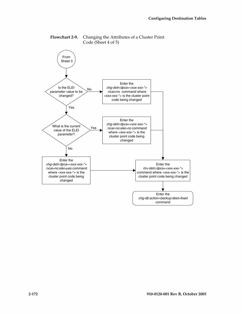
2-172 910-0120-001 Rev B, October 2005
Configuring Destination Tables
Flowchart 2-9. Changing the Attributes of a Cluster Point Code (Sheet 4 of 5)
Enter thechg-db:action=backup:dest=fixed
command
From Sheet 3
Enter thechg-dstn:dpca=<xxx-xxx-*>:ncai=no:elei=yes command
where <xxx-xxx-*> is thecluster point code being
changed
Enter thertrv-dstn:dpca=<xxx-xxx-*>
command where <xxx-xxx-*> is thecluster point code being changed
What is the currentvalue of the ELEI
parameter?
Is the ELEIparameter value to be
changed?
Yes
No
No
Yes
Enter thechg-dstn:dpca=<xxx-xxx-*>:ncai=no:elei=no commandwhere <xxx-xxx-*> is thecluster point code being
changed
Enter thechg-dstn:dpca=<xxx-xxx-*>:ncai=no command where
<xxx-xxx-*> is the cluster pointcode being changed

Configuring Destination Tables
910-0120-001 Rev B, October 2005 2-173
Flowchart 2-9. Changing the Attributes of a Cluster Point Code (Sheet 5 of 5)
Enter thechg-db:action=backup:dest=fixed
command
From Sheet 3
Enter thechg-dstn:dpca=<xxx-xxx-*>
:ncai=yes:elei=yes commandwhere <xxx-xxx-*> is thecluster point code being
changed
Enter thertrv-dstn:dpca=<xxx-xxx-*> commandwhere <xxx-xxx-*> is the cluster point
code that was changed
What is the currentvalue of the ELEI
parameter?
Is the ELEIparameter value to be
changed?
Yes
NoNo
Yes
Enter thechg-dstn:dpca=<xxx-xxx-*>:ncai=yes:elei=no command
where <xxx-xxx-*> is thecluster point code being
changed
Enter thechg-dstn:dpca=<xxx-xxx-*>:ncai=yes command where
<xxx-xxx-*> is the cluster pointcode being changed
Is the nestedcluster routing feature on
(NCR = on)?
Enter thertrv-feat command
Enter thechg-feat:ncr=on
command
Yes
No

2-174 910-0120-001 Rev B, October 2005
Configuring Destination Tables
Network Routing
Network routing allows the user to provision a single routeset that can used for all MSUs destined to members of that network. The advantages of network routing are:
• Reduces the number of entries in the route table
• Allows routing to members of a network without having to add those members to the route table
A EAGLE 5 SAS user can connect to a remote network by provisioning a single route table element. As the remote network grows, the EAGLE 5 SAS user does not have to add new route table entries for each new point code in the remote network.
NOTE: Network routing can be used only with ANSI point codes.
Types of Routing Strategies Available
The EAGLE 5 SAS currently allows a user to provision two types of routing strategies:
• Full point code routing
• Network/cluster routing (also called cluster routing)
This feature allows the user to provision a third type of routing strategy, network routing.
It is possible to provision full point code entries, cluster entries, and network entries for members of the same network. Any overlaps in the routing strategies are handled by a specific searching hierarchy.
All of these route table entries can coexist:
• 8-1-1 – A full point code entry
• 8-1-* – A cluster entry
• 8-*-* – A network entry
The searching hierarchy tries to match against a full point code entry first, followed by a cluster entry, and finally a network entry. In the preceding example, when the EAGLE 5 SAS routes an MSU destined for 8-1-1, it uses the full point code entry; when the EAGLE 5 SAS routes an MSU destined for 8-1-2 it uses the cluster entry; and when the EAGLE 5 SAS routes an MSU destined for 8-2-2, it uses the network entry.
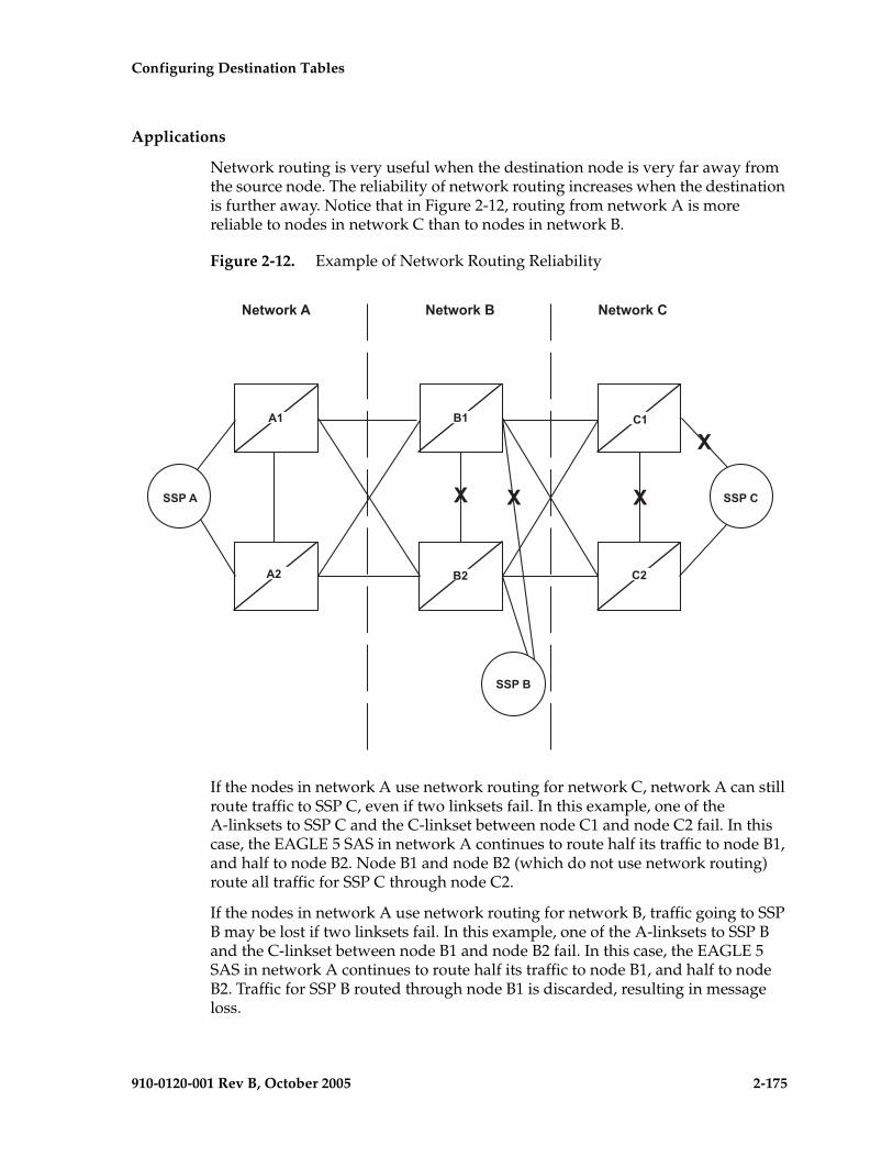
Configuring Destination Tables
910-0120-001 Rev B, October 2005 2-175
Applications
Network routing is very useful when the destination node is very far away from the source node. The reliability of network routing increases when the destination is further away. Notice that in Figure 2-12, routing from network A is more reliable to nodes in network C than to nodes in network B.
Figure 2-12. Example of Network Routing Reliability
If the nodes in network A use network routing for network C, network A can still route traffic to SSP C, even if two linksets fail. In this example, one of the A-linksets to SSP C and the C-linkset between node C1 and node C2 fail. In this case, the EAGLE 5 SAS in network A continues to route half its traffic to node B1, and half to node B2. Node B1 and node B2 (which do not use network routing) route all traffic for SSP C through node C2.
If the nodes in network A use network routing for network B, traffic going to SSP B may be lost if two linksets fail. In this example, one of the A-linksets to SSP B and the C-linkset between node B1 and node B2 fail. In this case, the EAGLE 5 SAS in network A continues to route half its traffic to node B1, and half to node B2. Traffic for SSP B routed through node B1 is discarded, resulting in message loss.
��
��
��
����� �����
��
�� ����
�����
��
�� ���� �� ����
��
� � �
�

2-176 910-0120-001 Rev B, October 2005
Configuring Destination Tables
Route Availability
A route is one path to a destination. A routeset is a list of paths to a destination. Route availability consists of two parts:
• Local availability
• Remote availability
Remote availability is affected by TFx network management messages. Local availability is affected by linkset failures and recoveries. TFx messages do not affect point codes accessed by network route entries. Therefore, for network route entries, route availability consists of only local availability. The highest priority linkset available for traffic is used for routing MSUs, regardless of the remote availability of that route.
Figure 2-13. Potential Routing Network Failure
In the example in Figure 2-13, linksets LS-C and LS-D form a combined route to network route 7-*-*. Because 7-*-* is a network route, the EAGLE 5 SAS always considers the non-adjacent status of the routes to be allowed. In the example shown, the EAGLE 5 SAS routes traffic destined to 7-7-1 over LS-C and LS-D. The EAGLE 5 SAS ignores TFPs concerning 7-7-1 or TCPs concerning 7-7-*.
Point Code Availability
A point code that is accessed by a network route entry is considered available if there is any linkset in the routeset that is available for traffic.
�
������
����������
����
����
�� �������������� ���� ��
� ��� �� ��� !
�
�
"�#���$ ���
"�#�$ ���
�
��
�

Configuring Destination Tables
910-0120-001 Rev B, October 2005 2-177
Route Management
Local Link Congestion
This feature has no impact on the generation of TFC messages. A TFC is generated concerning point code X-Y-Z, even if X-Y-Z is routed using a network route entry.
Remote Congestion
Because the EAGLE 5 SAS has global title capabilities, it is possible for the EAGLE 5 SAS to receive a TFC concerning a point code that is accessed by a network route entry. Network route entries are not affected by TFC messages.
Broadcast Transfer Messages
The EAGLE 5 SAS does not broadcast TFx messages for network route entries.
Response Method Transfer Messages
The EAGLE 5 SAS sends response method TFx messages for network routes as follows:
• Prohibited Network Routes
If the EAGLE 5 SAS receives an MSU that is accessed by a network route entry, and that network route is Prohibited, the EAGLE 5 SAS sends a response method TFP or TCP message, as follows:
– If there is a full point code defined in the same cluster as the MSU (for example, 8-*-* and 8-1-1 are defined in the EAGLE 5 SAS's routing table, and MSU is destined for 8-1-2), the EAGLE 5 SAS sends a TFP with concerned point code set to the MSU's DPC.
– Otherwise, the EAGLE 5 SAS sends a TCP with concerned point code set to the cluster of the MSU's DPC.
The EAGLE 5 SAS sends response method TCPs or TFPs at a rate of one TCP or TFP per signaling link during the level 3 T8 timer period for each network route.
For example, in Figure 2-13 on page 2-176, the network route for 7-*-* becomes Prohibited due to the failure of LS-B, LS-C, and LS-D. When the EAGLE 5 SAS receives an MSU from X destined for 7-7-1, the EAGLE 5 SAS sends a response method TCP concerning 7-7-*. When the EAGLE 5 SAS receives an MSU from X destined for 7-8-2, the EAGLE 5 SAS sends a response method TCP concerning 7-8-*.

2-178 910-0120-001 Rev B, October 2005
Configuring Destination Tables
• System Detects Danger of Circular Routing
If the EAGLE 5 SAS receives an MSU that is accessed by a network route entry, and the EAGLE 5 SAS detects danger of circular routing, the EAGLE 5 SAS sends a response method TFP or TCP message, as follows:
– If there is a full point code defined in the same cluster as the MSU (for example, 8-*-* and 8-1-1 are defined in the EAGLE 5 SAS's routing table, and the MSU is destined for 8-1-2), the EAGLE 5 SAS sends a TFP with concerned point code set to the MSU's DPC.
– Otherwise, the EAGLE 5 SAS sends a TCP with concerned point code set to the cluster of the MSU's DPC.
The EAGLE 5 SAS sends response method TCPs at a rate of one TCP per signaling link during the level 3 T8 timer period for each network route.
For example, in Figure 2-13 on page 2-176, all linksets are available. If the EAGLE 5 SAS receives an MSU from node C destined for 7-7-1, the EAGLE 5 SAS detects danger of circular routing, and sends a response method TCP concerning 7-7-*. The EAGLE 5 SAS also discards the MSU.
• Restricted Network Routes
If the EAGLE 5 SAS receives an MSU that is accessed by a network route entry, and that network route is Restricted, the EAGLE 5 SAS sends a one-time response method TFR or TCR message, as follows:
– If there is a full point code defined in the same cluster as the MSU (for example, 8-*-* and 8-1-1 are defined in the EAGLE 5 SAS's routing table, and MSU is destined for 8-1-2), the EAGLE 5 SAS sends a TFR with concerned point code set to the MSU's DPC.
– Otherwise, the EAGLE 5 SAS sends a TCR with concerned point code set to the cluster of the MSU's DPC.
For example, in Figure 2-13 on page 2-176, the network route for 7-*-* becomes Restricted due to the failure of LS-C and LS-D. When the EAGLE 5 SAS receives an MSU from X destined for 7-7-1, the EAGLE 5 SAS sends a response method TCR concerning 7-7-*, then routes the MSU over LS-B. When the EAGLE 5 SAS next receives an MSU from X destined for 7-8-2, the EAGLE 5 SAS does not send a response, and routes the MSU over LS-B.

Configuring Destination Tables
910-0120-001 Rev B, October 2005 2-179
Reception of Transfer Messages
The EAGLE 5 SAS does not apply received transfer messages to a network route.
For example, in Figure 2-13 on page 2-176, if the EAGLE 5 SAS receives a TFP concerning 7-7-1, it has no effect on the routing status of 7-*-*. The EAGLE 5 SAS continues to send MSUs destined to 7-*-*, including MSUs destined to 7-7-1, on LS-C.
As another example, if the EAGLE 5 SAS receives a TCP concerning 7-8-*, it has no effect on the routing status of 7-*-*. The EAGLE 5 SAS continues to send MSUs destined to 7-*-*, including MSUs destined to 7-8-2, on LS-C.
Reception of an RSx Message
If a routeset test (RSP or RSR) is received, a full point code reply (TFx) is generated. The responses to RSP/RSR have been changed according to Table 2-9. Note that the searching hierarchy applies.
Table 2-9. Reception of an RSx Message
Concerned Point Code is: Result
Found by a full point code match No change to existing rules.
Found by a cluster match No change to existing rules.
Found by a network match Send a TFx message based on the current routeset status.
• Send a TFP if danger of circular routing.
Otherwise:
• Send a TFA if the network route is Allowed.
• Send a TFR if the network route is Restricted.
• Send a TFP if the network route is Prohibited.
Not found No change to existing rules. Send a TFP.

2-180 910-0120-001 Rev B, October 2005
Configuring Destination Tables
Reception of an RCx Message
If a routeset cluster test (RCP or RCR) is received, a cluster reply (TCx) is generated. The responses to RCP/RCR have been changed according to Table 2-10. Note that the searching hierarchy applies.
Administration
The network routing feature must be on, before a network routing point code can be provisioned in the database. This can be verified with the entry NRT = on in the output of the rtrv-feat command. If the network routing feature is not on, NRT = off, it must be turned on with the chg-feat command using the nrt=on parameter. Once the network routing feature is on, the network routing point code can be provisioned in the database like any other destination point code. Routes can then be assigned to the network routing point code like any other destination point code. For more information on provisioning network routing point codes, see the “Adding a Network Routing Point Code” procedure on page 2-181.
NOTE: Once the network routing feature is turned on using the chg-feat command, it cannot be turned off. When using the network routing feature, limited network management is provided for point codes not covered by full point code routing, cluster routing, or nested cluster routing.
The network routing feature must be purchased before you turn this feature on with the chg-feat command. If you are not sure if you have purchased the network routing feature, contact your Tekelec Sales Representative or Account Representative.
Table 2-10. Reception of an RCx Message
Concerned Point Code is: Result
Found by a cluster match No change to existing rules.
Found by a network match Send a TCx message based on the current routeset status.
• Send a TCP if danger of circular routing.
Otherwise:
• Send a TCA if the network route is Allowed.
• Send a TCR if the network route is Restricted.
• Send a TCP if the network route is Prohibited.
Not found No change to existing rules. Send a TCP.

Configuring Destination Tables
910-0120-001 Rev B, October 2005 2-181
Adding a Network Routing Point Code
This procedure is used to add a destination point code to the database, using the ent-dstn command.
To change the attributes of an existing network routing point code, go to the “Changing a Destination Point Code” procedure on page 2-226.
To remove a network routing point code from the database, go to the “Removing a Destination Point Code” procedure on page 2-214.
The ent-dstn command uses these parameters:
:dpc/dpca– The destination point code being added to the database
NOTE: See “Point Code Formats” on page 2-4 for a definition of the point code types that are used on the EAGLE 5 SAS. Alias point codes (aliasi/aliasn/aliasn24) and secondary point codes (spc/spca) cannot be specified for a network routing point code. An ANSI private point code must be a full point code.
:clli – The Common Language Location Identifier assigned to this point code
:domain – The network in which the destination entity or node exists, X.25 or SS7
NOTE: Specifying the domain=x25 parameter is not valid for network routing destination point codes.
:bei – Broadcast exception indicator that indicates whether transfer-prohibited (TFP) messages will be broadcast from this node. The bei=yes parameter means TFPs will not be broadcast. The bei=no parameter means TFPs will be broadcast.
:ipgwapc – (ANSI networks only) IP Gateway Adjacent Point Code indicator. Specify ipgwapc=yes to provide SS7 linkset definition compatibility for gateway connections to IP-SCPs. The default is ipgwapc=no.
:elei – For cluster point codes only. Specifies whether or not the EAGLE 5 SAS maintains a dynamic status exception list for each cluster route that may be used to reach the member signaling points making up the cluster.
NOTE: See the “Cluster Routing and Management Diversity (CRMD)” section on page 2-119 and the “Adding a Cluster Point Code” procedure on page 2-142 for more information on the cluster routing feature and the elei parameter.
:ncai – The nested-cluster-allowed indicator specifies whether or not the route to the cluster point code can be different from the route to a point code that is a member of the cluster point code.
NOTE: See the “Nested Cluster Routing” section on page 2-135 and the “Adding a Cluster Point Code” procedure on page 2-142 for more information on the nested cluster routing feature and the ncai parameter.

2-182 910-0120-001 Rev B, October 2005
Configuring Destination Tables
The network routing point code must be in the SS7 domain (domain=ss7) and can only be an ANSI point code. ITU point codes cannot be specified as network routing point codes.
The ncai, spc, and elei parameters cannot be specified with a network routing point code.
The value of the clli parameter cannot be in the DPC table and cannot match the CLLI of the EAGLE 5 SAS. Verify this by entering the rtrv-dstn and the rtrv-sid commands, shown in steps 1 and 2 of the procedure that follows. If the value of the clli parameter matches any CLLI values in either of these outputs, choose another value for the clli parameter that does not match any CLLIs shown in either of these command outputs.
To enter the dpc/dpca parameter with the ent-dstn command, a point code must be defined in the PCA field of the self ID of the EAGLE 5 SAS. Verify this with the rtrv-sid command.
If no value is shown in the PCA field in the rtrv-sid command output, the self-identification of the EAGLE 5 SAS must be updated with an ANSI point code. Go to “Changing the Self-Identification of the EAGLE 5 SAS” procedure on page 2-90 to change the self-identification of the EAGLE 5 SAS.
NOTE: To enter a network routing point code with the network indicator values 1 through 5, the pctype parameter value of the chg-sid command must be set to other. If you attempt to add a network routing point code with the network indicator values 1 through 5 and the pctype parameter value is ansi, the ent-dstn command will be rejected with this error message.E2169 Cmd Rej: Point code out of range
Destination point codes must be unique in the database.
The actual number of destination point codes that can be configured in the database is set by the mtpdpcq parameter of the chg-stpopts command, and is shown in the MTPDPCQ field in the rtrv-stpopts command output.
If the 5000 Routes feature is not on, and 6000, 7000, or 8000 routesets are not enabled, a maximum of 2000 destination point codes can be configured in the database.
If the 5000 Routes feature is on, and 6000, 7000, or 8000 routesets are not enabled, a maximum of 5000 destination point codes can be configured in the database.
If 6000 routesets are enabled, a maximum of 6000 destination point codes can be configured in the database.
If 7000 routesets are enabled, a maximum of 7000 destination point codes can be configured in the database.

Configuring Destination Tables
910-0120-001 Rev B, October 2005 2-183
If 8000 routesets are enabled, a maximum of 8000 destination point codes can be configured in the database.
NOTE: For more information on the destination point code quantities, go to the “Changing the DPC Quantity” procedure on page 2-23.
The examples in this procedure are used to add the network routing point code 007-*-* to the database.
Canceling the RTRV-DSTN Command
Because the rtrv-dstn command used in this procedure can output information for a long period of time, the rtrv-dstn command can be canceled and the output to the terminal stopped. There are three ways that the rtrv-dstn command can be canceled:
• Press the F9 function key on the keyboard at the terminal where the rtrv-dstn command was entered.
• Enter the canc-cmd without the trm parameter at the terminal where the rtrv-dstn command was entered.
• Enter the canc-cmd:trm=<xx>, where <xx> is the terminal where the rtrv-dstn command was entered, from another terminal other than the terminal where the rtrv-dstn command was entered. To enter the canc-cmd:trm=<xx> command, the terminal must allow Security Administration commands to be entered from it and the user must be allowed to enter Security Administration commands. The terminal’s permissions can be verified with the rtrv-secu-trm command. The user’s permissions can be verified with the rtrv-user or rtrv-secu-user commands.
For more information about the canc-cmd command, refer to the Commands Manual.
Procedure
1. Display the current destination point codes using the rtrv-dstn command. This is an example of the possible output.
rlghncxa03w 05-09-17 16:02:05 GMT EAGLE5 34.0.0 DPCA CLLI BEI ELEI ALIASI ALIASN/N24 DOMAIN 001-002-003 ls04clli yes --- ---------- -------------- SS7 030-045-* rlghncbb010 yes yes ---------- -------------- SS7 111-011-* rlghncbb000 yes yes ---------- -------------- SS7 240-012-004 rlghncbb001 yes --- 1-111-1 10-13-9-3 SS7 240-012-005 rlghncbb002 yes --- 1-112-2 10-13-10-0 SS7 240-012-006 rlghncbb003 yes --- 1-112-3 10-13-10-1 SS7 240-012-008 ----------- yes --- 1-113-5 10-13-10-2 SS7 244-020-004 ls06clli yes --- ---------- -------------- X25 244-020-005 ls07clli yes --- ---------- -------------- X25 244-020-006 ls08clli yes --- ---------- -------------- X25 244-020-007 ----------- yes --- ---------- -------------- X25 244-020-008 ----------- yes --- ---------- -------------- X25

2-184 910-0120-001 Rev B, October 2005
Configuring Destination Tables
DPCI CLLI BEI ELEI ALIASA ALIASN/N24 DOMAIN 2-131-1 rlghncbb023 no --- 222-210-000 11-11-8-1 SS7 2-131-2 ----------- no --- 222-211-001 11-11-8-2 SS7 2-131-3 ----------- no --- 222-211-002 11-11-8-3 SS7
DPCN CLLI BEI ELEI ALIASA ALIASI DOMAIN 10-15-2-3 rlghncbb013 no --- 222-200-200 2-121-1 SS7 10-15-3-0 rlghncbb013 no --- 222-200-201 2-121-2 SS7
DPCN24 CLLI BEI ELEI ALIASA ALIASI DOMAIN
DESTINATION ENTRIES ALLOCATED: 6000 FULL DPC(s): 14 NETWORK DPC(s): 0 CLUSTER DPC(s): 2 TOTAL DPC(s): 16 CAPACITY (% FULL): 1%ALIASES ALLOCATED: 8000 ALIASES USED: 18 CAPACITY (% FULL): 1%X-LIST ENTRIES ALLOCATED: 500RTRV-DSTN: MASP A - COMPLTD
If the addition of the network routing point code will not exceed the current DPC capacity shown in the rtrv-dstn output, go to step 2.
If the addition of the network routing point code will exceed the current DPC capacity, and the current capacity is less than 8000 (or 8500 if the DESTINATION ENTRIES ALLOCATED and X-LIST ENTRIES ALLOCATED fields are shown in the rtrv-dstn output), perform the “Changing the DPC Quantity” procedure on page 2-23 to change the DPC quantity. Then go to step 2.
If the addition of the network routing point code will exceed the current DPC capacity, and the current capacity is 8000 (or 8500 if the DESTINATION ENTRIES ALLOCATED and X-LIST ENTRIES ALLOCATED fields are shown in the rtrv-dstn output), perform the “Removing a Destination Point Code” procedure on page 2-214 to remove a DPC. Then go to step 2.
2. Verify that the network routing feature is on, by entering the rtrv-feat command. If the network routing feature is on, the NRT field should be set to on. For this example, the network routing feature is off.
NOTE: The rtrv-feat command output contains other fields that are not used by this procedure. If you wish to see all the fields displayed by the rtrv-feat command, see the rtrv-feat command description in the Commands Manual.
If the network routing feature is on, skip this step and go to step 3.

Configuring Destination Tables
910-0120-001 Rev B, October 2005 2-185
3. If the network routing feature is not on, shown by the NRT = off entry in the rtrv-feat command output of step 2, turn the network routing feature on by entering this command.
chg-feat:nrt=on
NOTE: Once the network routing feature is turned on with the chg-feat command, it cannot be turned off.
The network routing feature must be purchased before you turn this feature on with the chg-feat command. If you are not sure if you have purchased the network routing feature, contact your Tekelec Sales Representative or Account Representative.
When the chg-feat has successfully completed, this message should appear.
rlghncxa03w 05-09-07 00:57:31 GMT EAGLE5 34.0.0CHG-FEAT: MASP A - COMPLTD
NOTES:1. If network routing point codes with the network indicator values 1
through 5 are shown in the rtrv-dstn command output in step 1, skip this step and go to step 5.
2. If you wish to enter a network routing point code with the network indicator values 1 through 5, perform this step to verify the pctype value.
3. If ANSI point codes are not shown in the rtrv-dstn output in step 1, perform this step to verify that an ANSI point code is assigned to the self-identification of the EAGLE 5 SAS.
4. If network routing point codes or ANSI point codes are shown in the rtrv-dstn command output in step 1, and you do not wish to enter a network routing point code with the network indicator values 1 through 5, skip this step and go to step 5.
4. Display the self-identification of the EAGLE 5 SAS using the rtrv-sid command. This is an example of the possible output.
rlghncxa03w 05-09-10 11:43:04 GMT EAGLE5 34.0.0 PCA PCI PCN CLLI PCTYPE 100-100-100 3-75-7 7-9-8-1 rlghncxa03w OTHER
CPCA 002-002-002 002-002-003 002-002-004 002-002-005 002-002-006 002-002-007 002-002-008 002-002-009 004-002-001 004-003-003 050-060-070
CPCA (LNP) 005-005-002 005-005-004 005-005-005
CPCI 1-002-1 1-002-2 1-002-3 1-002-4 2-001-1 7-222-7
CPCN 2-0-10-3 2-0-11-0 2-0-11-2 2-0-12-1 2-2-3-3 2-2-4-0 10-14-10-1

2-186 910-0120-001 Rev B, October 2005
Configuring Destination Tables
To enter an ANSI destination point code with the ent-dstn command, a point code must be shown in the PCA field of the rtrv-sid command output.
If the required point code is not shown in the PCA field of the rtrv-sid command output, go to the “Changing the Self-Identification of the EAGLE 5 SAS” procedure on page 2-90 and configure the required point codes.
To enter a network routing point code with the network indicator values 1 through 5, the pctype parameter value of the chg-sid command must be set to other. If you wish to enter a network routing point code with a network indicator value 1 through 5, and the pctype parameter value is ansi, perform the “Changing the Self-Identification of the EAGLE 5 SAS” procedure on page 2-90 and change the pctype value to other.
NOTE: If the rtrv-dstn command output in step 1 shows network routing point codes, skip steps 3 and 3, and go to step 5.
5. Add the network routing destination point code, using the ent-dstn command. For this example, enter this command.
ent-dstn:dpca=007-*-*
When this command has successfully completed, and the Cluster Routing and Management Diversity feature is turned off (shown with the CRMD = off entry in the rtrv-feat command output), this message should appear.
rlghncxa03w 05-09-17 15:35:05 GMT EAGLE5 34.0.0Destination table is (17 of 2000) 1% full ENT-DSTN: MASP A - COMPLTD
If the Cluster Routing and Management Diversity feature is turned on (CRMD = on in the rtrv-feat command output), this message should appear when each command has successfully completed.
rlghncxa03w 05-09-17 15:35:05 GMT EAGLE5 34.0.0DESTINATION ENTRIES ALLOCATED: 6000 FULL DPC(s): 14 NETWORK DPC(s): 1 CLUSTER DPC(s): 2 TOTAL DPC(s): 17 CAPACITY (% FULL): 1%ALIASES ALLOCATED: 8000 ALIASES USED: 18 CAPACITY (% FULL): 1%X-LIST ENTRIES ALLOCATED: 500ENT-DSTN: MASP A - COMPLTD
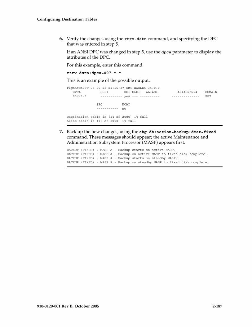
Configuring Destination Tables
910-0120-001 Rev B, October 2005 2-187
6. Verify the changes using the rtrv-dstn command, and specifying the DPC that was entered in step 5.
If an ANSI DPC was changed in step 5, use the dpca parameter to display the attributes of the DPC.
For this example, enter this command.
rtrv-dstn:dpca=007-*-*
This is an example of the possible output.
rlghncxa03w 05-09-28 21:16:37 GMT EAGLE5 34.0.0 DPCA CLLI BEI ELEI ALIASI ALIASN/N24 DOMAIN 007-*-* ----------- yes --- ---------- -------------- SS7
SPC NCAI ----------- no
Destination table is (14 of 2000) 1% fullAlias table is (18 of 8000) 1% full
7. Back up the new changes, using the chg-db:action=backup:dest=fixed command. These messages should appear; the active Maintenance and Administration Subsystem Processor (MASP) appears first.
BACKUP (FIXED) : MASP A - Backup starts on active MASP.BACKUP (FIXED) : MASP A - Backup on active MASP to fixed disk complete.BACKUP (FIXED) : MASP A - Backup starts on standby MASP.BACKUP (FIXED) : MASP A - Backup on standby MASP to fixed disk complete.
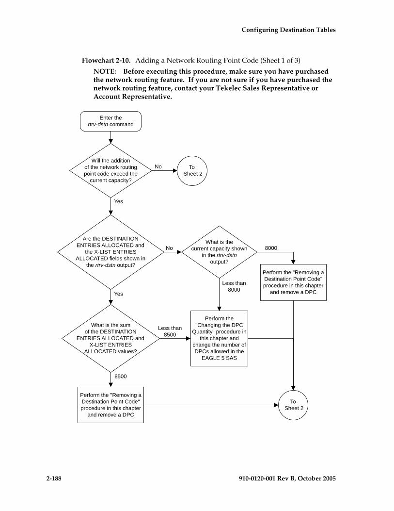
2-188 910-0120-001 Rev B, October 2005
Configuring Destination Tables
Flowchart 2-10. Adding a Network Routing Point Code (Sheet 1 of 3)
NOTE: Before executing this procedure, make sure you have purchased the network routing feature. If you are not sure if you have purchased the network routing feature, contact your Tekelec Sales Representative or Account Representative.
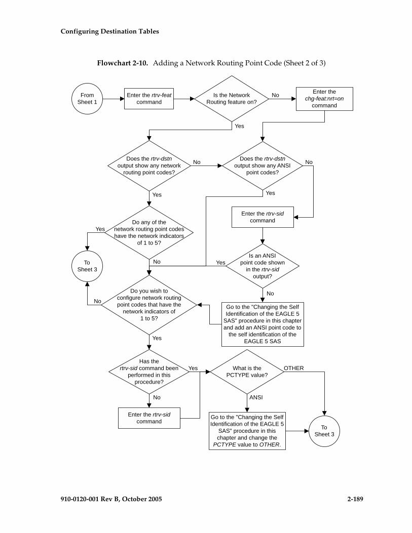
Configuring Destination Tables
910-0120-001 Rev B, October 2005 2-189
Flowchart 2-10. Adding a Network Routing Point Code (Sheet 2 of 3)

2-190 910-0120-001 Rev B, October 2005
Configuring Destination Tables
Flowchart 2-10. Adding a Network Routing Point Code (Sheet 3 of 3)
FromSheet 2
Enter thertrv-dstn command with this
parameter::dpca=<network routing point codespecified in the ent-dstn command>
Enter thechg-db:action=backup:dest=fixed
command
Is the networkrouting DPC in the
database?
Select another networkrouting DPC to add to the
database
Enter theent-dstn command with this
parameter::dpca=<network routing point code>
Yes
No
Configuring Destination Tables
910-0120-001 Rev B, October 2005 2-191
Adding a Destination Point Code
This procedure is used to add a destination point code to the database, using the ent-dstn command.
The ent-dstn command uses these parameters:
:dpc/dpca/dpci/dpcn/dpcn24 – The destination point code being added to the database
:aliasa/aliasi/aliasn/aliasn24 – The alternate destination point code. Two optional alias addresses can be defined.
NOTE: If 7000 or 8000 routesets are enabled, the EAGLE 5 SAS can contain a maximum of 8000 alias point codes. If 7000 or 8000 routesets are not enabled, the EAGLE 5 SAS can contain a maximum of 12000 alias point codes.
NOTE: See “Point Code Formats” on page 2-4 for a definition of the point code types that are used on the EAGLE 5 SAS and for a definition of the different formats that can be used for ITU national point codes. A private point code cannot be used as an alias point code.
:clli – The Common Language Location Identifier assigned to this point code
:domain – The network in which the destination entity or node exists, X.25 or SS7
NOTE: Specifying :domain=x25 is valid only for ANSI destinations.
:ipgwapc – IP Gateway Adjacent Point Code indicator. Specify ipgwapc=yes to provide SS7 linkset definition compatibility for gateway connections to IP-SCPs. The default is ipgwapc=no.
:bei – Broadcast exception indicator that indicates whether transfer-prohibited (TFP) messages will be broadcast from this node. The bei=yes parameter means TFPs will not be broadcast. The bei=no parameter means TFPs will be broadcast.
:spc/spca/spci/spcn/spcn24 – The secondary point code as defined by the ent-spc command. The secondary point code allows the EAGLE 5 SAS to use another point code in addition to the one defined by the dpc, dpca, dpci, dpcn, or dpcn24 parameters of the ent-dstn command for SS7 routing purposes. See the “Multiple Point Code Support” section on page 2-55 for more information on secondary point codes. A private point code cannot be used as a secondary point code.
:elei – For cluster point codes only. Specifies whether or not the EAGLE 5 SAS maintains a dynamic status exception list for each cluster route that may be used to reach the member signaling points making up the cluster.
NOTE: See the “Cluster Routing and Management Diversity (CRMD)” section on page 2-119 and the “Adding a Cluster Point Code” procedure on page 2-142 for more information on the cluster routing feature and the elei parameter.

2-192 910-0120-001 Rev B, October 2005
Configuring Destination Tables
:ncai – The nested-cluster-allowed indicator specifies whether or not the route to the cluster point code can be different from the route to a point code that is a member of the cluster point code.
NOTE: See the “Nested Cluster Routing” section on page 2-135 and the “Adding a Cluster Point Code” procedure on page 2-142 for more information on the nested cluster routing feature and the ncai parameter.
Secondary point codes must be in the SS7 domain and must be a full point code. A secondary point code can only be assigned to a full point code in the SS7 domain. The network type of the secondary point code must match the network type of the DPC. The secondary point code used in this procedure must be configured in the database with the ent-spc command. The secondary point codes are shown in the SPCA, SPC-I, SPC-N, and SPC-N24 fields of the rtrv-spc command output. If the desired secondary point code is not shown in the output of the rtrv-spc command, go to the “Adding a Secondary Point Code” procedure on page 2-63 and configure the desired point code as a secondary point code.
If the dpci, dpcn, dpcn24, aliasa, aliasi, aliasn, aliasn24, or spc, spca, spci, spcn, or spcn24 parameters are specified with the ent-dstn command, the domain of the DPC must be SS7 (domain=ss7).
To specify the domain=x25 parameter with the ent-dstn command, the X.25 gateway feature must be turned on. Verify this with the rtrv-feat command. If the X.25 gateway feature is turned on, the X25G field should be set to on. If the X.25 gateway feature is not turned on, enter the chg-feat:x25g=on command.
NOTE: Once the X.25 gateway feature is turned on with the chg-feat command, it cannot be turned off.
For provisioning of SS7IPGW ISUP-CIC routing keys, the ipgwapc=yes parameter and the IP Gateway ISUP routing feature must be turned on. Verify this with the rtrv-feat command. If the IP Gateway ISUP routing feature is turned on, the ipisup field should be set to on. If the IP Gateway ISUP routing feature is not turned on, enter the chg-feat:ipisup=on command.
NOTE: Once the IP Gateway ISUP routing feature is turned on with the chg-feat command, it cannot be turned off.
NOTE: The SS7IPGW application applies to ANSI networks only.
The value of the clli parameter cannot be in the DPC table and cannot match the CLLI of the EAGLE 5 SAS. Verify this by entering the rtrv-dstn and the rtrv-sid commands, shown in steps 1 and 5 of the procedure that follows. If the value of the clli parameter matches any CLLI values in either of these outputs, choose another value for the clli parameter that does not match any CLLIs shown in either of these command outputs.
Configuring Destination Tables
910-0120-001 Rev B, October 2005 2-193
To enter point codes of any network type (ANSI, ITU-I, 14-bit ITU-N, or 24-bit ITU-N) into the database with the ent-dstn command, the self ID of the EAGLE 5 SAS must be defined for these networks. Verify this with the rtrv-sid command.
If a point code value is shown in the PCA column of the rtrv-sid command, then ANSI point codes can be specified with the ent-dstn command.
If a point code value is shown in the PCI column of the output of the rtrv-sid command, then ITU-I point codes can be specified with the ent-dstn command. The PCI column of the rtrv-sid output can contain spare and non-spare point code values. To provision ITU-I non-spare point codes in this procedure, the rtrv-sid output must contain an ITU-I non-spare point code in the PCI column. To provision ITU-I spare point codes in this procedure, the rtrv-sid output must contain an ITU-I spare point code in the PCI column.
If a point code value is shown in the PCN column of the output of the rtrv-sid command, then 14-bit ITU-N point codes can be specified with the ent-dstn command. The PCN column of the rtrv-sid output can contain spare and non-spare point code values. To provision 14-bit ITU-N non-spare point codes in this procedure, the rtrv-sid output must contain a 14-bit ITU-N non-spare point code in the PCN column. To provision 14-bit ITU-N spare point codes in this procedure, the rtrv-sid output must contain a 14-bit ITU-N spare point code in the PCN column.
If a point code value is shown in the PCN24 column of the output of the rtrv-sid command, then 24-bit ITU-N point codes can be specified with the ent-dstn command.
If no values are shown in the PCA, PCI, PCN, or PCN24 columns in the rtrv-sid command output, the self-identification of the EAGLE 5 SAS must be updated with an ANSI point code, ITU international point code, 14-bit ITU national point code, or a 24-bit ITU national point code. Go to “Adding a Point Code to the Self-Identification of the EAGLE 5 SAS” procedure on page 2-81 to add the necessary point codes to the self-identification of the EAGLE 5 SAS.
NOTE: The EAGLE 5 SAS can contain 14-bit ITU national point codes or 24-bit ITU national point codes, but both at the same time.
Private point codes cannot be specified in the self-identification of the EAGLE 5 SAS, therefore, private point codes can be added as long as the self identification of the EAGLE 5 SAS contains a point code with the same network type as the private point code being added in this procedure. The ITU National and International Spare Point Code Support feature does not have to be enabled to add a private point code.

2-194 910-0120-001 Rev B, October 2005
Configuring Destination Tables
If the alias point code parameters aliasa, aliasi, aliasn, or aliasn24 are specified with the ent-dstn command, the aliases must be of a different point code type than the true point code. For example, if the dpca parameter is specified, then only the aliasi, aliasn, or aliasn24 parameters can be specified. The aliasa parameter cannot be specified. Table 2-11 shows which alias parameters can be specified with the destination point code parameters.
Alias point codes can only be specified for full point code entries, and must be full point codes.
ANSI alias point codes cannot be a member of a cluster point code that is already in the database. A point code is a member of a cluster point code if it has the same network identifier (NI) and network cluster (NC) values as the cluster point code.
Destination point codes and alias point codes must be unique in the database. A point code can be defined as a true destination point code, an alias point code, the self ID of the EAGLE 5 SAS, or the capability point code of the EAGLE 5 SAS. The self IDs and capability point codes of the EAGLE 5 SAS can be verified with the rtrv-sid command.
If the X.25 destination point code is a member of a cluster, the value of the bei parameter for the X.25 destination point code is not changed to the value of the bei parameter of the cluster, but the value of the bei parameter of the cluster determines the behavior of the X.25 destination point code as long as the cluster remains in the DPC table. If this cluster is removed from the DPC table, the X.25 destination behaves as it is configured with the ent-dstn command. For example, if the X.25 destination point code, 002-002-002, is a member of the cluster 002-002-*, the bei parameter of the cluster is set to yes, and the bei parameter of the X.25 destination point code is set to no, the X.25 destination point code behaves as if the bei parameter is set to yes. If the cluster 002-002-* is removed from the database, the bei parameter of the X.25 destination point code is set to no and the X.25 destination point code broadcasts TFP and TFA messages to adjacent nodes.
Table 2-11. Destination Point Code and Alias Parameter Combinations
Destination Point Code Parameters
Alias Point Code Parameters
dpc/dpca aliasi, aliasn/aliasn24*
dpci aliasa, aliasn/aliasn24*
dpcn/dpcn24* aliasa, aliasi
* The EAGLE 5 SAS can contain 14-bit ITU national point codes or 24-bit ITU national point codes, but both at the same time.
Configuring Destination Tables
910-0120-001 Rev B, October 2005 2-195
If you intend to use an X.25 destination point code with an X.25 route that has the lc2nm parameter set to yes, make sure that the bei parameter of the cluster containing the X.25 destination point code is set to no. Verify the value of the bei parameter of the cluster with the rtrv-dstn command. To change the existing value the bei parameter, go to the “Changing a Destination Point Code” procedure on page 2-226.
For X.25 destination point codes or members of a cluster that have the value of the bei parameter set to yes, the default value of the bei parameter is yes. For cluster destination point codes, or members of a cluster that have the value of the bei parameter set to no, the default value of the bei parameter is no.
The elei (exception list exclusion indicator) parameter can be specified only for a cluster destination point code. Cluster destination point codes and the elei parameter can be specified only if the Cluster Routing and Management Diversity feature is turned on. Verify this with the rtrv-feat command. If the Cluster Routing and Management Diversity feature is turned on, the CRMD field should be set to on. If the Cluster Routing and Management Diversity feature is not turned on, enter the chg-feat:crmd=on command. For more information on the Cluster Routing and Management Diversity feature, go to the “Cluster Routing and Management Diversity (CRMD)” section on page 2-119.
NOTE: Once the Cluster Routing and Management Diversity feature is turned on with the chg-feat command, it cannot be turned off.
If the PCTYPE field of the rtrv-sid command output contains the entry ANSI, and the network value of the destination point code specified by the ent-dstn command is from 0 to 5, the cluster value of that point code must be from 1 to 255. If the network value of that point code is from 6 to 255, the cluster value of that point code must be from 0 to 255.
The actual number of destination point codes that can be configured in the database is set by the mtpdpcq parameter of the chg-stpopts command, and is shown in the MTPDPCQ field in the rtrv-stpopts command output.
If the 5000 Routes feature is not on, and 6000, 7000, or 8000 routesets are not enabled, a maximum of 2000 destination point codes can be configured in the database.
If the 5000 Routes feature is on, and 6000, 7000, or 8000 routesets are not enabled, a maximum of 5000 destination point codes can be configured in the database.
If 6000 routesets are enabled, a maximum of 6000 destination point codes can be configured in the database.
If 7000 routesets are enabled, a maximum of 7000 destination point codes can be configured in the database.
If 8000 routesets are enabled, a maximum of 8000 destination point codes can be configured in the database.
NOTE: For more information on the destination point code quantities, go to the “Changing the DPC Quantity” procedure on page 2-23.
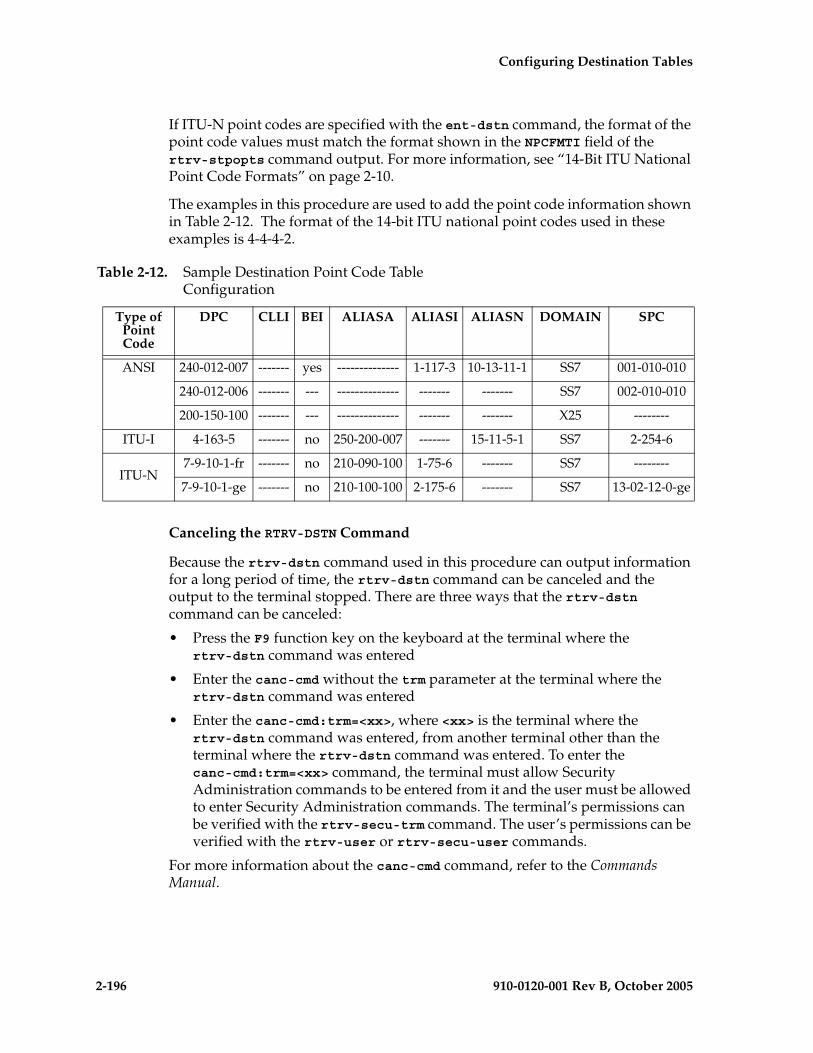
2-196 910-0120-001 Rev B, October 2005
Configuring Destination Tables
If ITU-N point codes are specified with the ent-dstn command, the format of the point code values must match the format shown in the NPCFMTI field of the rtrv-stpopts command output. For more information, see “14-Bit ITU National Point Code Formats” on page 2-10.
The examples in this procedure are used to add the point code information shown in Table 2-12. The format of the 14-bit ITU national point codes used in these examples is 4-4-4-2.
Canceling the RTRV-DSTN Command
Because the rtrv-dstn command used in this procedure can output information for a long period of time, the rtrv-dstn command can be canceled and the output to the terminal stopped. There are three ways that the rtrv-dstn command can be canceled:
• Press the F9 function key on the keyboard at the terminal where the rtrv-dstn command was entered
• Enter the canc-cmd without the trm parameter at the terminal where the rtrv-dstn command was entered
• Enter the canc-cmd:trm=<xx>, where <xx> is the terminal where the rtrv-dstn command was entered, from another terminal other than the terminal where the rtrv-dstn command was entered. To enter the canc-cmd:trm=<xx> command, the terminal must allow Security Administration commands to be entered from it and the user must be allowed to enter Security Administration commands. The terminal’s permissions can be verified with the rtrv-secu-trm command. The user’s permissions can be verified with the rtrv-user or rtrv-secu-user commands.
For more information about the canc-cmd command, refer to the Commands Manual.
Table 2-12. Sample Destination Point Code Table Configuration
Type of Point Code
DPC CLLI BEI ALIASA ALIASI ALIASN DOMAIN SPC
ANSI 240-012-007 ------- yes -------------- 1-117-3 10-13-11-1 SS7 001-010-010
240-012-006 ------- --- -------------- ------- ------- SS7 002-010-010
200-150-100 ------- --- -------------- ------- ------- X25 --------
ITU-I 4-163-5 ------- no 250-200-007 ------- 15-11-5-1 SS7 2-254-6
ITU-N7-9-10-1-fr ------- no 210-090-100 1-75-6 ------- SS7 --------
7-9-10-1-ge ------- no 210-100-100 2-175-6 ------- SS7 13-02-12-0-ge

Configuring Destination Tables
910-0120-001 Rev B, October 2005 2-197
Procedure
1. Display the current destination point codes, using the rtrv-dstn command. This is an example of the possible output.
rlghncxa03w 05-09-17 16:02:05 GMT EAGLE5 34.0.0 DPCA CLLI BEI ELEI ALIASI ALIASN/N24 DOMAIN 001-002-003 ls04clli yes --- ---------- -------------- SS7 030-045-* rlghncbb010 yes yes ---------- -------------- SS7 111-011-* rlghncbb000 yes yes ---------- -------------- SS7 240-012-004 rlghncbb001 yes --- 1-111-1 10-13-9-3-fr SS7 240-012-005 rlghncbb002 yes --- 1-112-2 10-13-10-0-ge SS7 240-012-006 rlghncbb003 yes --- 1-112-3 10-13-10-1-fr SS7 240-012-008 ----------- yes --- 1-113-5 10-13-10-2-ge SS7 244-020-004 ls06clli yes --- ---------- -------------- X25 244-020-005 ls07clli yes --- ---------- -------------- X25 244-020-006 ls08clli yes --- ---------- -------------- X25 244-020-007 ----------- yes --- ---------- -------------- X25 244-020-008 ----------- yes --- ---------- -------------- X25
DPCI CLLI BEI ELEI ALIASA ALIASN/N24 DOMAIN 2-131-1 rlghncbb023 no --- 222-210-000 11-11-8-1-ge SS7 2-131-2 ----------- no --- 222-211-001 11-11-8-2-fr SS7 2-131-3 ----------- no --- 222-211-002 11-11-8-3-ge SS7
DPCN CLLI BEI ELEI ALIASA ALIASI DOMAIN 10-15-2-3-fr rlghncbb013 no --- 222-200-200 2-121-1 SS7 10-15-2-3-ge rlghncbb013 no --- 222-100-200 2-100-1 SS7 10-15-3-0-fr rlghncbb013 no --- 222-200-201 2-121-2 SS7 10-15-3-0-ge rlghncbb013 no --- 222-100-201 2-100-2 SS7
DPCN24 CLLI BEI ELEI ALIASA ALIASI DOMAIN
DESTINATION ENTRIES ALLOCATED: 2000 FULL DPC(s): 18 NETWORK DPC(s): 0 CLUSTER DPC(s): 2 TOTAL DPC(s): 20 CAPACITY (% FULL): 1%ALIASES ALLOCATED: 8000 ALIASES USED: 22 CAPACITY (% FULL): 1%X-LIST ENTRIES ALLOCATED: 500RTRV-DSTN: MASP A - COMPLTD
If the addition of the destination point code will not exceed the current DPC capacity shown in the rtrv-dstn output, go to step 2.If the addition of the destination point code will exceed the current DPC capacity, and the current capacity is less than 8000 (or 8500 if the DESTINATION ENTRIES ALLOCATED and X-LIST ENTRIES ALLOCATED fields are shown in the rtrv-dstn output), perform the “Changing the DPC Quantity” procedure on page 2-23 to change the DPC quantity. Then go to step 2.If the addition of the destination point code will exceed the current DPC capacity, and the current capacity is 8000 (or 8500 if the DESTINATION ENTRIES ALLOCATED and X-LIST ENTRIES ALLOCATED fields are shown in the rtrv-dstn output), perform the “Removing a Destination Point Code” procedure on page 2-214 to remove a DPC. Then go to step 2.
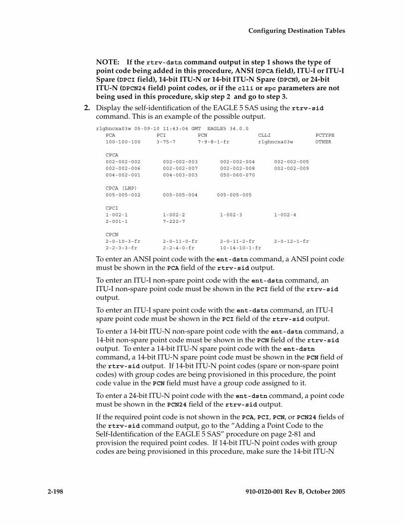
2-198 910-0120-001 Rev B, October 2005
Configuring Destination Tables
NOTE: If the rtrv-dstn command output in step 1 shows the type of point code being added in this procedure, ANSI (DPCA field), ITU-I or ITU-I Spare (DPCI field), 14-bit ITU-N or 14-bit ITU-N Spare (DPCN), or 24-bit ITU-N (DPCN24 field) point codes, or if the clli or spc parameters are not being used in this procedure, skip step 2 and go to step 3.
2. Display the self-identification of the EAGLE 5 SAS using the rtrv-sid command. This is an example of the possible output.
rlghncxa03w 05-09-10 11:43:04 GMT EAGLE5 34.0.0 PCA PCI PCN CLLI PCTYPE 100-100-100 3-75-7 7-9-8-1-fr rlghncxa03w OTHER
CPCA 002-002-002 002-002-003 002-002-004 002-002-005 002-002-006 002-002-007 002-002-008 002-002-009 004-002-001 004-003-003 050-060-070
CPCA (LNP) 005-005-002 005-005-004 005-005-005
CPCI 1-002-1 1-002-2 1-002-3 1-002-4 2-001-1 7-222-7
CPCN 2-0-10-3-fr 2-0-11-0-fr 2-0-11-2-fr 2-0-12-1-fr 2-2-3-3-fr 2-2-4-0-fr 10-14-10-1-fr
To enter an ANSI point code with the ent-dstn command, a ANSI point code must be shown in the PCA field of the rtrv-sid output.
To enter an ITU-I non-spare point code with the ent-dstn command, an ITU-I non-spare point code must be shown in the PCI field of the rtrv-sid output.
To enter an ITU-I spare point code with the ent-dstn command, an ITU-I spare point code must be shown in the PCI field of the rtrv-sid output.
To enter a 14-bit ITU-N non-spare point code with the ent-dstn command, a 14-bit non-spare point code must be shown in the PCN field of the rtrv-sid output. To enter a 14-bit ITU-N spare point code with the ent-dstn command, a 14-bit ITU-N spare point code must be shown in the PCN field of the rtrv-sid output. If 14-bit ITU-N point codes (spare or non-spare point codes) with group codes are being provisioned in this procedure, the point code value in the PCN field must have a group code assigned to it.
To enter a 24-bit ITU-N point code with the ent-dstn command, a point code must be shown in the PCN24 field of the rtrv-sid output.
If the required point code is not shown in the PCA, PCI, PCN, or PCN24 fields of the rtrv-sid command output, go to the “Adding a Point Code to the Self-Identification of the EAGLE 5 SAS” procedure on page 2-81 and provision the required point codes. If 14-bit ITU-N point codes with group codes are being provisioned in this procedure, make sure the 14-bit ITU-N
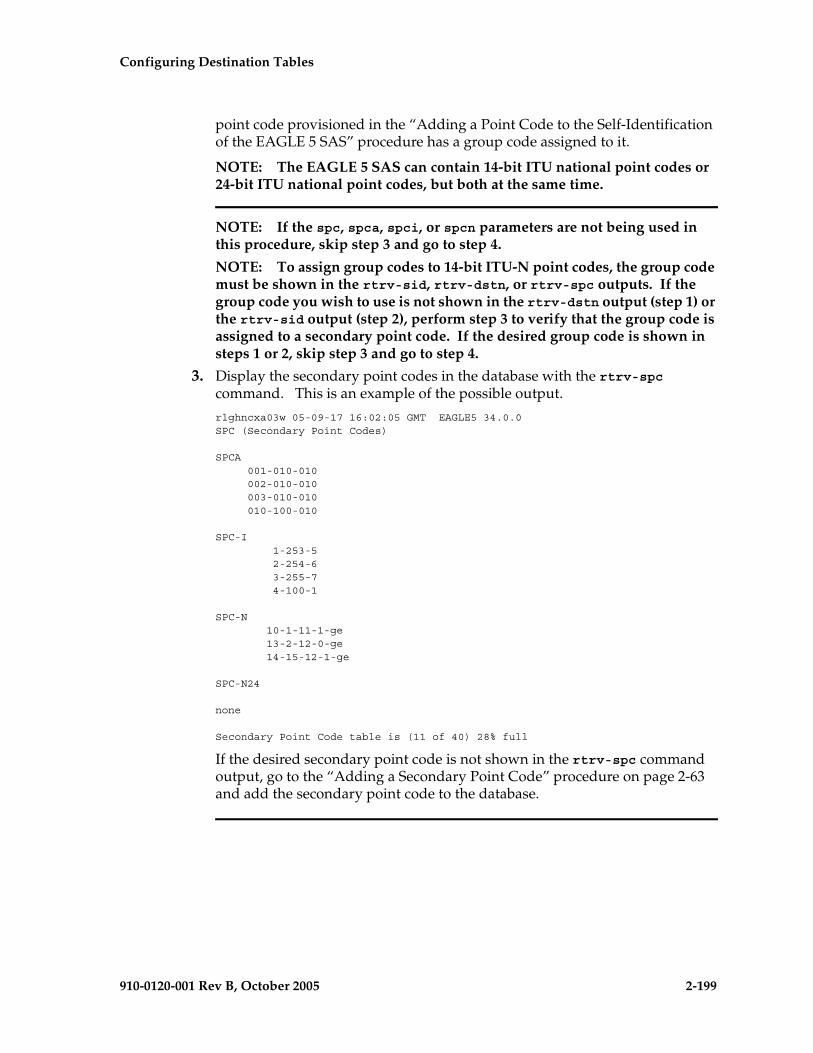
Configuring Destination Tables
910-0120-001 Rev B, October 2005 2-199
point code provisioned in the “Adding a Point Code to the Self-Identification of the EAGLE 5 SAS” procedure has a group code assigned to it.
NOTE: The EAGLE 5 SAS can contain 14-bit ITU national point codes or 24-bit ITU national point codes, but both at the same time.
NOTE: If the spc, spca, spci, or spcn parameters are not being used in this procedure, skip step 3 and go to step 4.
NOTE: To assign group codes to 14-bit ITU-N point codes, the group code must be shown in the rtrv-sid, rtrv-dstn, or rtrv-spc outputs. If the group code you wish to use is not shown in the rtrv-dstn output (step 1) or the rtrv-sid output (step 2), perform step 3 to verify that the group code is assigned to a secondary point code. If the desired group code is shown in steps 1 or 2, skip step 3 and go to step 4.
3. Display the secondary point codes in the database with the rtrv-spc command. This is an example of the possible output.
rlghncxa03w 05-09-17 16:02:05 GMT EAGLE5 34.0.0SPC (Secondary Point Codes)
SPCA 001-010-010 002-010-010 003-010-010 010-100-010
SPC-I 1-253-5 2-254-6 3-255-7 4-100-1
SPC-N 10-1-11-1-ge 13-2-12-0-ge 14-15-12-1-ge
SPC-N24
none
Secondary Point Code table is (11 of 40) 28% full
If the desired secondary point code is not shown in the rtrv-spc command output, go to the “Adding a Secondary Point Code” procedure on page 2-63 and add the secondary point code to the database.

2-200 910-0120-001 Rev B, October 2005
Configuring Destination Tables
NOTE: If ITU-N point codes are not being used in this procedure, skip step 4 and go to step 5.
4. Display the existing values for the npcfmti parameter by entering the rtrv-stpopts command. The value for the npcfmti parameter is shown in the NPCFMTI field. This is an example of the possible output.rlghncxa03w 05-09-17 16:02:05 GMT EAGLE5 34.0.0STP OPTIONS-----------------------NPCFMTI 4-4-4-2
NOTE: The rtrv-stpopts command output contains other fields that are not used by this procedure. If you wish to see all the fields displayed by the rtrv-stpopts command, see the rtrv-stpopts command description in the Commands Manual.
If you wish to change the format of the 14-bit ITU national point codes, go to “14-Bit ITU National Point Code Formats” section on page 2-10. Changing the formats of the 14-bit ITU national point codes will change how any existing 14-bit ITU national point codes are displayed in the database.
NOTE: If the domain of the DPC is to be SS7, or if the rtrv-dstn command output in step 1 shows X.25 point codes, (the entry X25 is in the DOMAIN field), skip steps 5 and 6, and go to step 9.
5. Verify that the X.25 gateway feature is on, by entering the rtrv-feat command. If the X.25 gateway feature is on, the X25G field should be set to on. For this example, the X.25 gateway feature is off.
NOTE: The rtrv-feat command output contains other fields that are not used by this procedure. If you wish to see all the fields displayed by the rtrv-feat command, see the rtrv-feat command description in the Commands Manual.
If the X.25 gateway feature is on, skip step 5 and go to step 6.
6. If the X.25 gateway feature is not on, shown by the X25G = off entry in the rtrv-feat command output in step 5, turn the X.25 gateway feature on by entering this command.
chg-feat:x25g=on
NOTE: Once the X.25 gateway feature is turned on with the chg-feat command, it cannot be turned off.
The X.25 gateway feature must be purchased before you turn this feature on with the chg-feat command. If you are not sure if you have purchased the X.25 gateway feature, contact your Tekelec Sales Representative or Account Representative.
When the chg-feat has successfully completed, this message should appear.
rlghncxa03w 05-09-07 00:57:31 GMT EAGLE5 34.0.0CHG-FEAT: MASP A - COMPLTD

Configuring Destination Tables
910-0120-001 Rev B, October 2005 2-201
NOTE: If alias point codes are not being provisioned in this procedure, skip steps 7 and 8, and go to step 9.
NOTE: If the DPC quantity shown in the rtrv-dstn output in step 1 is from 6001 to 8000, skip step 7 and go to step 8.
7. Verify that either 6000, 7000, or 8000 routesets are enabled by entering the rtrv-ctrl-feat command. The following is an example of the possible output.
rlghncxa03w 05-09-28 21:15:37 GMT EAGLE5 34.0.0The following features have been permanently enabled:
Feature Name Partnum Status QuantityIPGWx Signaling TPS 893012814 on 20000ISUP Normalization 893000201 on ----Command Class Management 893005801 on ----LNP Short Message Service 893006601 on ----Intermed GTT Load Sharing 893006901 on ----XGTT Table Expansion 893006101 on 4000000XMAP Table Expansion 893007710 on 3000Large System # Links 893005901 on 1500Routesets 893006401 on 6000HC-MIM SLK Capacity 893012707 on 64
The following features have been temporarily enabled:
Feature Name Partnum Status Quantity Trial Period LeftZero entries found.
The following features have expired temporary keys:
Feature Name PartnumZero entries found.
8. The number of routesets that are enabled is shown in the rtrv-ctrl-feat output in step 7 with the quantity of 6000, 7000, or 8000 in the Routesets row. If 6000, 7000, or 8000 routesets are not enabled, the EAGLE 5 SAS can contain a maximum or either 2000 or 5000 routesets. The routeset quantity enabled is also shown by the DPC quantity in the rtrv-dstn output in step 1. If the DPC quantity is from 6001 to 8000, either 7000 or 8000 routesets have been enabled.
If 7000 or 8000 routesets are enabled, the EAGLE 5 SAS can contain a maximum of 8000 alias point codes. If 7000 or 8000 routesets are not enabled, the EAGLE 5 SAS can contain a maximum of 12000 alias point codes.
If the alias point code being added will exceed the maximum number of alias point codes the EAGLE 5 SAS is allowed to have, other alias point codes will have to be removed before this alias point code can be added. Perform the “Changing a Destination Point Code” procedure on page 2-226 to remove alias point codes. Then go to step 9 to add the destination point code with an alias point code. If you do not wish to remove other alias point codes, do not perform the “Changing a Destination Point Code” procedure on page 2-226. Go to step 9 to add the destination point code without an alias point code.
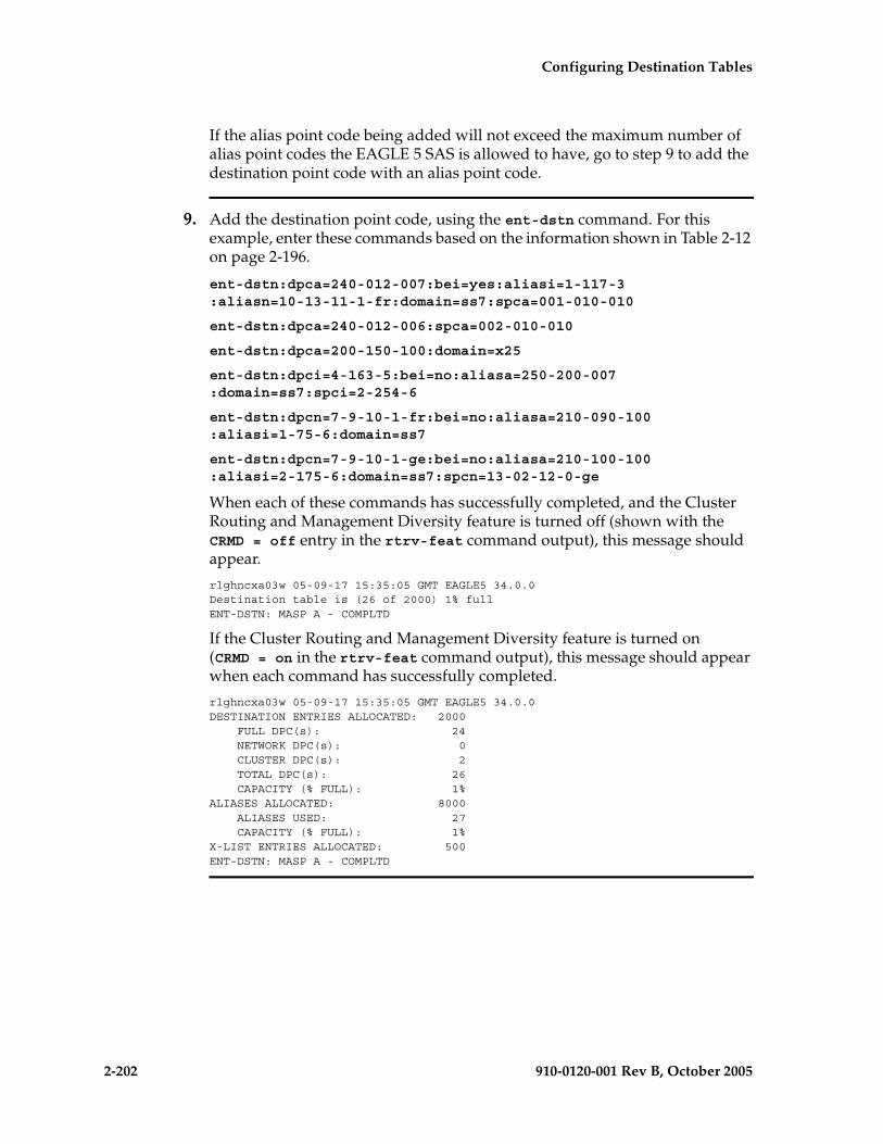
2-202 910-0120-001 Rev B, October 2005
Configuring Destination Tables
If the alias point code being added will not exceed the maximum number of alias point codes the EAGLE 5 SAS is allowed to have, go to step 9 to add the destination point code with an alias point code.
9. Add the destination point code, using the ent-dstn command. For this example, enter these commands based on the information shown in Table 2-12 on page 2-196.
ent-dstn:dpca=240-012-007:bei=yes:aliasi=1-117-3:aliasn=10-13-11-1-fr:domain=ss7:spca=001-010-010
ent-dstn:dpca=240-012-006:spca=002-010-010
ent-dstn:dpca=200-150-100:domain=x25
ent-dstn:dpci=4-163-5:bei=no:aliasa=250-200-007:domain=ss7:spci=2-254-6
ent-dstn:dpcn=7-9-10-1-fr:bei=no:aliasa=210-090-100:aliasi=1-75-6:domain=ss7
ent-dstn:dpcn=7-9-10-1-ge:bei=no:aliasa=210-100-100:aliasi=2-175-6:domain=ss7:spcn=13-02-12-0-ge
When each of these commands has successfully completed, and the Cluster Routing and Management Diversity feature is turned off (shown with the CRMD = off entry in the rtrv-feat command output), this message should appear.
rlghncxa03w 05-09-17 15:35:05 GMT EAGLE5 34.0.0Destination table is (26 of 2000) 1% full ENT-DSTN: MASP A - COMPLTD
If the Cluster Routing and Management Diversity feature is turned on (CRMD = on in the rtrv-feat command output), this message should appear when each command has successfully completed.
rlghncxa03w 05-09-17 15:35:05 GMT EAGLE5 34.0.0DESTINATION ENTRIES ALLOCATED: 2000 FULL DPC(s): 24 NETWORK DPC(s): 0 CLUSTER DPC(s): 2 TOTAL DPC(s): 26 CAPACITY (% FULL): 1%ALIASES ALLOCATED: 8000 ALIASES USED: 27 CAPACITY (% FULL): 1%X-LIST ENTRIES ALLOCATED: 500ENT-DSTN: MASP A - COMPLTD

Configuring Destination Tables
910-0120-001 Rev B, October 2005 2-203
10. Verify the changes using the rtrv-dstn command with the dpca parameter, and specifying the DPC that was entered in step 9.
For this example, enter these commands.
rtrv-dstn:dpca=240-012-007
This is an example of the possible output.
rlghncxa03w 05-09-28 21:16:37 GMT EAGLE5 34.0.0 DPCA CLLI BEI ELEI ALIASI ALIASN/N24 DOMAIN 240-012-007 ----------- yes --- 1-117-3 10-13-11-1-fr SS7
SPC NCAI 001-010-010 no
DESTINATION ENTRIES ALLOCATED: 2000 FULL DPC(s): 24 NETWORK DPC(s): 0 CLUSTER DPC(s): 2 TOTAL DPC(s): 26 CAPACITY (% FULL): 1%ALIASES ALLOCATED: 8000 ALIASES USED: 27 CAPACITY (% FULL): 1%X-LIST ENTRIES ALLOCATED: 500RTRV-DSTN: MASP A - COMPLTD
rtrv-dstn:dpca=240-012-006
This is an example of the possible output.
rlghncxa03w 05-09-28 21:16:37 GMT EAGLE5 34.0.0 DPCA CLLI BEI ELEI ALIASI ALIASN/N24 DOMAIN 240-012-006 rlghncbb003 yes --- 1-112-3 10-13-10-1-fr SS7
SPC NCAI 002-010-010 no
DESTINATION ENTRIES ALLOCATED: 2000 FULL DPC(s): 24 NETWORK DPC(s): 0 CLUSTER DPC(s): 2 TOTAL DPC(s): 26 CAPACITY (% FULL): 1%ALIASES ALLOCATED: 8000 ALIASES USED: 27 CAPACITY (% FULL): 1%X-LIST ENTRIES ALLOCATED: 500RTRV-DSTN: MASP A - COMPLTD
rtrv-dstn:dpca=200-150-100
This is an example of the possible output.
rlghncxa03w 05-09-28 21:16:37 GMT EAGLE5 34.0.0 DPCA CLLI BEI ELEI ALIASI ALIASN/N24 DOMAIN 200-150-100 ----------- yes --- ---------- -------------- X25
SPC NCAI ----------- no
Destination table is (26 of 2000) 1% full
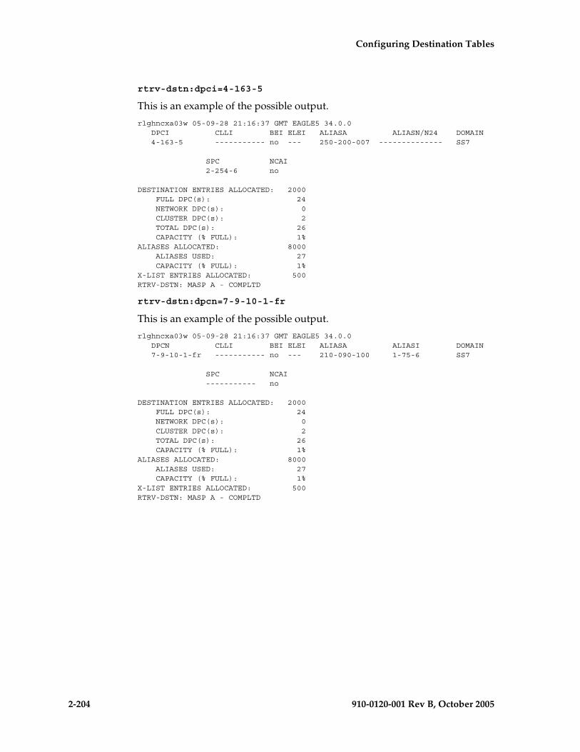
2-204 910-0120-001 Rev B, October 2005
Configuring Destination Tables
rtrv-dstn:dpci=4-163-5
This is an example of the possible output.
rlghncxa03w 05-09-28 21:16:37 GMT EAGLE5 34.0.0 DPCI CLLI BEI ELEI ALIASA ALIASN/N24 DOMAIN 4-163-5 ----------- no --- 250-200-007 -------------- SS7
SPC NCAI 2-254-6 no
DESTINATION ENTRIES ALLOCATED: 2000 FULL DPC(s): 24 NETWORK DPC(s): 0 CLUSTER DPC(s): 2 TOTAL DPC(s): 26 CAPACITY (% FULL): 1%ALIASES ALLOCATED: 8000 ALIASES USED: 27 CAPACITY (% FULL): 1%X-LIST ENTRIES ALLOCATED: 500RTRV-DSTN: MASP A - COMPLTD
rtrv-dstn:dpcn=7-9-10-1-fr
This is an example of the possible output.
rlghncxa03w 05-09-28 21:16:37 GMT EAGLE5 34.0.0 DPCN CLLI BEI ELEI ALIASA ALIASI DOMAIN 7-9-10-1-fr ----------- no --- 210-090-100 1-75-6 SS7
SPC NCAI ----------- no
DESTINATION ENTRIES ALLOCATED: 2000 FULL DPC(s): 24 NETWORK DPC(s): 0 CLUSTER DPC(s): 2 TOTAL DPC(s): 26 CAPACITY (% FULL): 1%ALIASES ALLOCATED: 8000 ALIASES USED: 27 CAPACITY (% FULL): 1%X-LIST ENTRIES ALLOCATED: 500RTRV-DSTN: MASP A - COMPLTD

Configuring Destination Tables
910-0120-001 Rev B, October 2005 2-205
rtrv-dstn:dpcn=7-9-10-1-ge
This is an example of the possible output.
rlghncxa03w 05-09-28 21:16:37 GMT EAGLE5 34.0.0 DPCN CLLI BEI ELEI ALIASA ALIASI DOMAIN 7-9-10-1-ge ----------- no --- 210-100-100 2-175-6 SS7
SPC NCAI 13-02-12-0-ge no
DESTINATION ENTRIES ALLOCATED: 2000 FULL DPC(s): 24 NETWORK DPC(s): 0 CLUSTER DPC(s): 2 TOTAL DPC(s): 26 CAPACITY (% FULL): 1%ALIASES ALLOCATED: 8000 ALIASES USED: 27 CAPACITY (% FULL): 1%X-LIST ENTRIES ALLOCATED: 500RTRV-DSTN: MASP A - COMPLTD
11. Back up the new changes, using the chg-db:action=backup:dest=fixed command. These messages should appear; the active Maintenance and Administration Subsystem Processor (MASP) appears first.
BACKUP (FIXED) : MASP A - Backup starts on active MASP.BACKUP (FIXED) : MASP A - Backup on active MASP to fixed disk complete.BACKUP (FIXED) : MASP A - Backup starts on standby MASP.BACKUP (FIXED) : MASP A - Backup on standby MASP to fixed disk complete.

2-206 910-0120-001 Rev B, October 2005
Configuring Destination Tables
Flowchart 2-11. Adding a Destination Point Code (Sheet 1 of 8)
NOTE: If you plan to provision X.25 point codes using this procedure, before executing this procedure, make sure you have purchased the X.25 gateway feature. If you are not sure if you have purchased the X.25 gateway feature, contact your Tekelec Sales Representative or Account Representative.
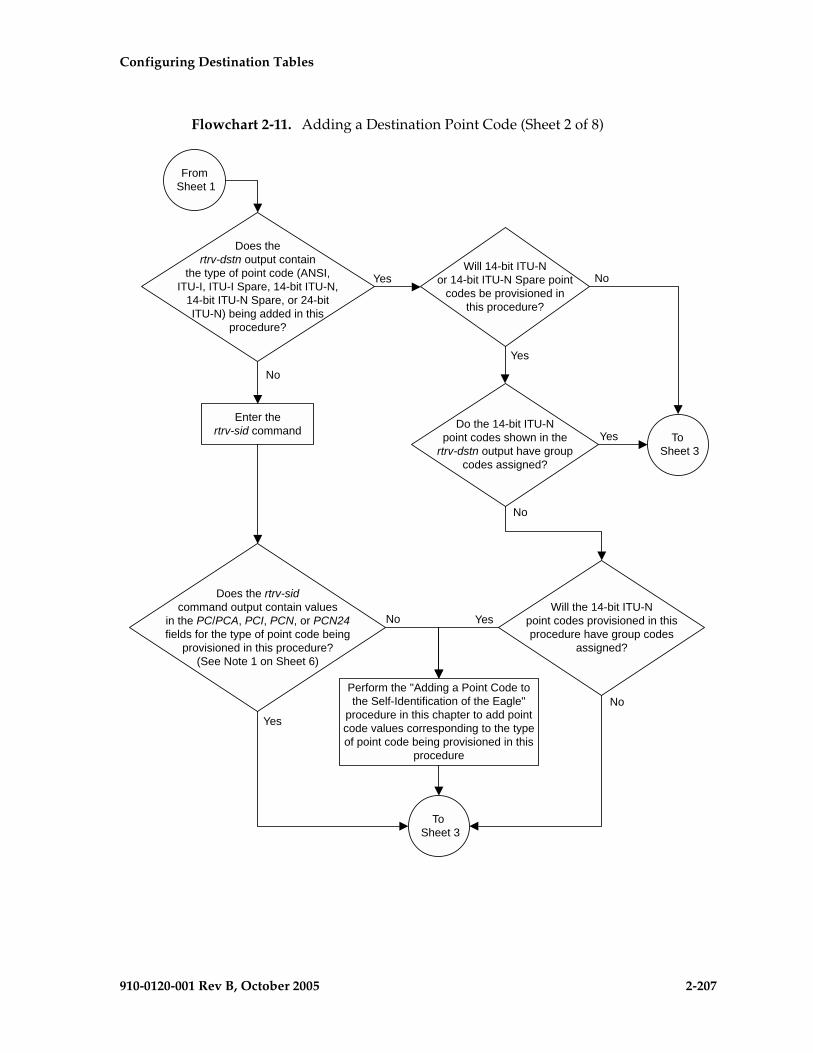
Configuring Destination Tables
910-0120-001 Rev B, October 2005 2-207
Flowchart 2-11. Adding a Destination Point Code (Sheet 2 of 8)

2-208 910-0120-001 Rev B, October 2005
Configuring Destination Tables
Flowchart 2-11. Adding a Destination Point Code (Sheet 3 of 8)

Configuring Destination Tables
910-0120-001 Rev B, October 2005 2-209
Flowchart 2-11. Adding a Destination Point Code (Sheet 4 of 8)
Enter thertrv-sid command
Is a CLLI valuefor the DPC to be
specified?
No
Does the newCLLI value match any CLLI
values shown in the rtrv-dstnor rtrv-sid outputs?
Choose a CLLI value thatdoes not match any CLLI
values shown in the rtrv-dstnor rtrv-sid outputs
Yes
To Sheet 5
From Sheet 3
No
Yes
Enter thertrv-stpopts command
Do you wish tochange the format of 14-bit
ITU national point codes shown inthe NPCFMTI field of the
rtrv-stpopts commandoutput?
Go to the "14-Bit ITUNational Point Code
Formats" section andchange the ITU national
point code format
Yes
No
Was the rtrv-sidcommand performed on
Sheet 2?
Yes
No

2-210 910-0120-001 Rev B, October 2005
Configuring Destination Tables
Flowchart 2-11. Adding a Destination Point Code (Sheet 5 of 8)
Enter thechg-feat:x25g=on
command
Enter thertrv-feat command
Yes
NoIs the X.25 feature on?
Enter theent-dstn command with these
mandatory parameters::dpca=<ANSI point code>
:domain=x25and these optional
parameters::clli=<CLLI value>
:bei=<yes, no>(See Note)
Enter thechg-db:action=backup:dest=fixed
command
From Sheet 4
Enter thertrv-dstn:dpca=<DPC value
specified in the ent-dstncommand> command
Is an ANSIpoint code being
provisioned?
Is the domain ofthe ANSI point code X.25
or SS7?
Yes
No
X.25 SS7
Note: If the X.25 destinationpoint code will be used withan X.25 route that has the
lc2nm parameter set to yes,make sure that the bei
parameter value is set to no.The default value of the beiparameter of an X.25 point
code is yes.
To Sheet 6

Configuring Destination Tables
910-0120-001 Rev B, October 2005 2-211
Flowchart 2-11. Adding a Destination Point Code (Sheet 6 of 8)
From Sheet 5
Are aliaspoint codes being
provisioned?
What is theDPC quantity shown inthe rtrv-dstn output on
Sheet 1?
6001 to8000
6000 orlessEnter the
rtrv-ctrl-feat command
Is 7000 or 8000routesets enabled?
How manyalias point codes are
currently configured (shownin the rtrv-dstn output
on Sheet 1)?
8000
7999or less
Yes
No
Will the alias pointcodes being added exceed
the maximum alias pointcode quantity?
Do youwish to add the alias
point codes?
Perform the "Changing aDestination Point Code"procedure and remove
enough of the alias pointcodes to allow the new alias
point codes to be added.
To Sheet 7
To Sheet 7
Yes
No
Yes
No
To Sheet 7

2-212 910-0120-001 Rev B, October 2005
Configuring Destination Tables
Flowchart 2-11. Adding a Destination Point Code (Sheet 7 of 8)
Enter thechg-db:action=backup:dest=fixed
command
From Sheet 6
Enter thertrv-dstn command specifyingthe DPC provisioned with the
ent-dstn command with:dpc/:dpca/:dpci/:dpcn/:dpcn24
parameters
Enter theent-dstn command with the
:dpc/:dpca/:dpci/:dpcn/:dpcn24=<pointcode value> parameter and these optional
parameters::domain=ss7
:clli=<CLLI value>:bei=<yes, no>
:aliasa/:aliasi/:aliasn/aliasn24=<alias pointcode value>
:spc/:spca/:spci/:spcn/:spcn24= <secondarypoint code value>
:ipgwapc=<yes, no>(See Notes on Sheet 8)
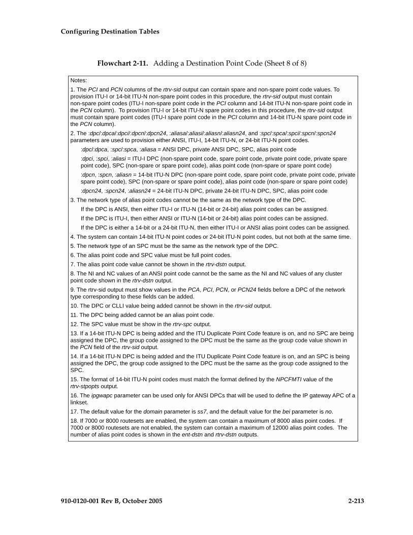
Configuring Destination Tables
910-0120-001 Rev B, October 2005 2-213
Flowchart 2-11. Adding a Destination Point Code (Sheet 8 of 8)

2-214 910-0120-001 Rev B, October 2005
Configuring Destination Tables
Removing a Destination Point Code
This procedure is used to remove a destination point code from the database, using the dlt-dstn command.
The dlt-dstn command uses this parameter:
:dpc/dpca/dpci/dpcn/dpcn24 – The destination point code being removed from the database
NOTE: See “Point Code Formats” on page 2-4 for a definition of the point code types that are used on the EAGLE 5 SAS and for a definition of the different formats that can be used for ITU national point codes.
The destination point code to be removed must exist in the database, but cannot be assigned to any routes. Enter the rtrv-rte command to see if the destination point code to be removed is assigned to any routes. If the destination point code is assigned to any routes, go to the “Removing a Route” procedure on page 3-189 to remove these routes.
The destination point code cannot be defined as an adjacent point code for a linkset. Enter the rtrv-ls to see if the destination point code to be removed is defined as an adjacent point code for a linkset. If the destination point code is defined as an adjacent point code for a linkset, go to the “Removing a Linkset Containing SS7 Signaling Links” procedure on page 3-63, or the “Removing a Linkset Containing X.25 Signaling Links” procedure in the Database Administration Manual – Features, depending on the domain of the linkset. The domain of the linkset is shown in the DOMAIN field of the rtrv-ls output.
A destination point code in the X.25 domain cannot be removed if it is referenced by an X.25 destination. Verify this with the rtrv-x25-dstn command. The destination point code is shown in the SS7 DPC field of the rtrv-x25-dstn command output. If the destination point code is shown in the SS7 DPC field of the rtrv-x25-dstn command, go to the “Removing an X.25 Gateway Destination” procedure in the Database Administration Manual – Features to remove these X.25 destinations.
The destination point code cannot be in the mated relay node (MRN) table. Verify this by entering the rtrv-mrn command, specifying the destination point code being removed from the database. If the destination point code is shown in the rtrv-mrn command output, remove the point code from the MRN table, by executing the “Removing an MRN Group or MRN Group Entry” procedure in the Database Administration Manual – Features.
The destination point code cannot be defined as an end office internal point code. Verify this by entering the rtrv-rmt-appl command. If the destination point code is shown in the rtrv-rmt-appl command output, go to the “Removing an End Node Internal Point Code” procedure in the Database Administration Manual - IP7 Secure Gateway to remove the internal point code.
The examples in this procedure are used to remove destination point codes 240-012-007 and 244-020-005.

Configuring Destination Tables
910-0120-001 Rev B, October 2005 2-215
Canceling the RTRV-DSTN, RTRV-MAP, and RTRV-LS Commands
Because the rtrv-dstn, rtrv-map, and rtrv-ls commands used in this procedure can output information for a long period of time, the rtrv-dstn, rtrv-map, and rtrv-ls commands can be canceled and the output to the terminal stopped. There are three ways that the rtrv-dstn, rtrv-map, and rtrv-ls commands can be canceled:
• Press the F9 function key on the keyboard at the terminal where the rtrv-dstn, rtrv-map, or rtrv-ls command was entered
• Enter the canc-cmd without the trm parameter at the terminal where the rtrv-dstn, rtrv-map, or rtrv-ls command was entered
• Enter the canc-cmd:trm=<xx>, where <xx> is the terminal where the rtrv-dstn, rtrv-map, or rtrv-ls command was entered, from another terminal other than the terminal where the rtrv-dstn, rtrv-map, or rtrv-ls command was entered. To enter the canc-cmd:trm=<xx> command, the terminal must allow Security Administration commands to be entered from it and the user must be allowed to enter Security Administration commands. The terminal’s permissions can be verified with the rtrv-secu-trm command. The user’s permissions can be verified with the rtrv-user or rtrv-secu-user commands.
For more information about the canc-cmd command, go to the Commands Manual.

2-216 910-0120-001 Rev B, October 2005
Configuring Destination Tables
Procedure
1. Display the current destination point codes, using the rtrv-dstn command. This is an example of the possible output.
rlghncxa03w 05-09-17 16:02:05 GMT EAGLE5 34.0.0 DPCA CLLI BEI ELEI ALIASI ALIASN/N24 DOMAIN 007-*-* ----------- yes --- ---------- -------------- SS7 030-045-* rlghncbb010 yes yes ---------- -------------- SS7 111-011-* rlghncbb000 yes yes ---------- -------------- SS7 240-012-004 rlghncbb001 yes --- 1-111-1 10-13-9-3-fr SS7 240-012-005 rlghncbb002 yes --- 1-112-2 10-13-10-0-ge SS7 240-012-006 rlghncbb003 yes --- 1-112-3 10-13-10-1-fr SS7 240-012-007 ----------- yes --- 1-117-3 10-13-11-1-fr SS7 240-012-008 ----------- yes --- 1-113-5 10-13-10-2-ge SS7 200-150-100 ----------- yes --- ---------- -------------- X25 244-020-004 ls06clli yes --- ---------- -------------- X25 244-020-005 ls07clli yes --- ---------- -------------- X25 244-020-006 ls08clli yes --- ---------- -------------- X25 244-020-007 ----------- yes --- ---------- -------------- X25 244-020-008 ----------- yes --- ---------- -------------- X25
DPCI CLLI BEI ELEI ALIASA ALIASN/N24 DOMAIN 2-131-1 rlghncbb023 no --- 222-210-000 11-11-8-1-ge SS7 2-131-2 ----------- no --- 222-211-001 11-11-8-2-fr SS7 2-131-3 ----------- no --- 222-211-002 11-11-8-3-ge SS7 4-163-5 ----------- no --- 250-200-007 -------------- SS7
DPCN CLLI BEI ELEI ALIASA ALIASI DOMAIN 7-9-10-1-fr -------- no --- 210-090-100 1-75-6 SS7 7-9-10-1-ge -------- no --- 210-100-100 2-175-6 SS7 10-15-2-3-fr rlghncbb013 no --- 222-200-200 2-121-1 SS7 10-15-2-3-ge rlghncbb013 no --- 222-100-200 2-100-1 SS7 10-15-3-0-fr rlghncbb013 no --- 222-200-201 2-121-2 SS7 10-15-3-0-ge rlghncbb013 no --- 222-100-201 2-100-2 SS7
DPCN24 CLLI BEI ELEI ALIASA ALIASI DOMAIN
DESTINATION ENTRIES ALLOCATED: 2000 FULL DPC(s): 21 NETWORK DPC(s): 1 CLUSTER DPC(s): 2 TOTAL DPC(s): 24 CAPACITY (% FULL): 1%ALIASES ALLOCATED: 8000 ALIASES USED: 29 CAPACITY (% FULL): 1%X-LIST ENTRIES ALLOCATED: 500RTRV-DSTN: MASP A - COMPLTD

Configuring Destination Tables
910-0120-001 Rev B, October 2005 2-217
2. Verify whether or not the DPC to be removed from the database is a DPC of a route, by entering the rtrv-rte command with the DPC that is to be removed from the database. For this example, enter these commands.
rtrv-rte:dpca=240-012-007
This is an example of the possible output.rlghncxa03w 05-09-17 16:02:05 GMT EAGLE5 34.0.0
DPCA ALIASI ALIASN/N24 LSN RC APCA 240-012-007 1-117-3 10-13-11-1-fr ls04 10 240-012-007 ls02 20 004-004-004 ls03 30 003-003-003 CLLI=ls04clli
rtrv-rte:dpca=244-020-005
rlghncxa03w 05-09-17 16:02:05 GMT EAGLE5 34.0.0 DPCA ALIASI ALIASN/N24 LSN RC APCA 244-020-005 ------ ----------- ls10 10 244-020-005 ls11 20 100-100-100 CLLI=ls07clli
If the DPC being removed from the database is a DPC of a route, go to the “Removing a Route” procedure on page 3-189 and remove the route from the database.
3. Verify whether or not the DPC to be removed from the database is an APC of a linkset, by entering the rtrv-ls command. This is an example of the possible output.
rlghncxa03w 05-09-10 11:43:04 GMT EAGLE5 34.0.0
L3T SLT GWS GWS GWSLSN APCA (SS7) SCRN SET SET BEI LST LNKS ACT MES DIS SLSCI NISe1e2 001-207-000 none 1 1 no B 6 off off off no offls1305 000-005-000 none 1 1 no A 1 off off off no offls1307 000-007-000 none 1 1 no A 1 off off off no offe1m1s1 001-001-001 none 1 1 no A 7 off off off no offe1m1s2 001-001-002 none 1 1 no A 7 off off off no off
L3T SLT GWS GWS GWSLSN APCA (X25) SCRN SET SET BEI LST LNKS ACT MES DIS SLSCI NIS
L3T SLT GWS GWS GWSLSN APCI (SS7) SCRN SET SET BEI LST LNKS ACT MES DIS SLSCI NISe1e2i 1-207-0 none 1 1 no B 4 off off off --- onls1315 0-015-0 none 1 1 no A 1 off off off --- offls1317 0-017-0 none 1 1 no A 1 off off off --- one1m2s1 1-011-1 none 1 1 no A 7 off off off --- offe1m2s2 1-011-2 none 1 1 no A 7 off off off --- off
L3T SLT GWS GWS GWSLSN APCN (SS7) SCRN SET SET BEI LST LNKS ACT MES DIS SLSCI NIS
L3T SLT GWS GWS GWSLSN APCN24 (SS7) SCRN SET SET BEI LST LNKS ACT MES DIS SLSCI NIS
L3T SLT GWS GWS GWSLSN (CHINA) APCN (SS7) SCRN SET SET BEI LST LNKS ACT MES DIS SLSCI NIS
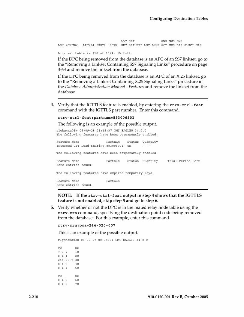
2-218 910-0120-001 Rev B, October 2005
Configuring Destination Tables
L3T SLT GWS GWS GWSLSN (CHINA) APCN24 (SS7) SCRN SET SET BEI LST LNKS ACT MES DIS SLSCI NIS
Link set table is (10 of 1024) 1% full.
If the DPC being removed from the database is an APC of an SS7 linkset, go to the “Removing a Linkset Containing SS7 Signaling Links” procedure on page 3-63 and remove the linkset from the database.
If the DPC being removed from the database is an APC of an X.25 linkset, go to the “Removing a Linkset Containing X.25 Signaling Links” procedure in the Database Administration Manual - Features and remove the linkset from the database.
4. Verify that the IGTTLS feature is enabled, by entering the rtrv-ctrl-feat command with the IGTTLS part number. Enter this command.
rtrv-ctrl-feat:partnum=893006901
The following is an example of the possible output.rlghncxa03w 05-09-28 21:15:37 GMT EAGLE5 34.0.0The following features have been permanently enabled:
Feature Name Partnum Status QuantityIntermed GTT Load Sharing 893006901 on ----
The following features have been temporarily enabled:
Feature Name Partnum Status Quantity Trial Period LeftZero entries found.
The following features have expired temporary keys:
Feature Name PartnumZero entries found.
NOTE: If the rtrv-ctrl-feat output in step 4 shows that the IGTTLS feature is not enabled, skip step 5 and go to step 6.
5. Verify whether or not the DPC is in the mated relay node table using the rtrv-mrn command, specifying the destination point code being removed from the database. For this example, enter this command.
rtrv-mrn:pca=244-020-007
This is an example of the possible output.
rlghncxa03w 05-09-07 00:34:31 GMT EAGLE5 34.0.0
PC RC7-7-7 108-1-1 20244-20-7 308-1-3 408-1-4 50
PC RC8-1-5 608-1-6 70
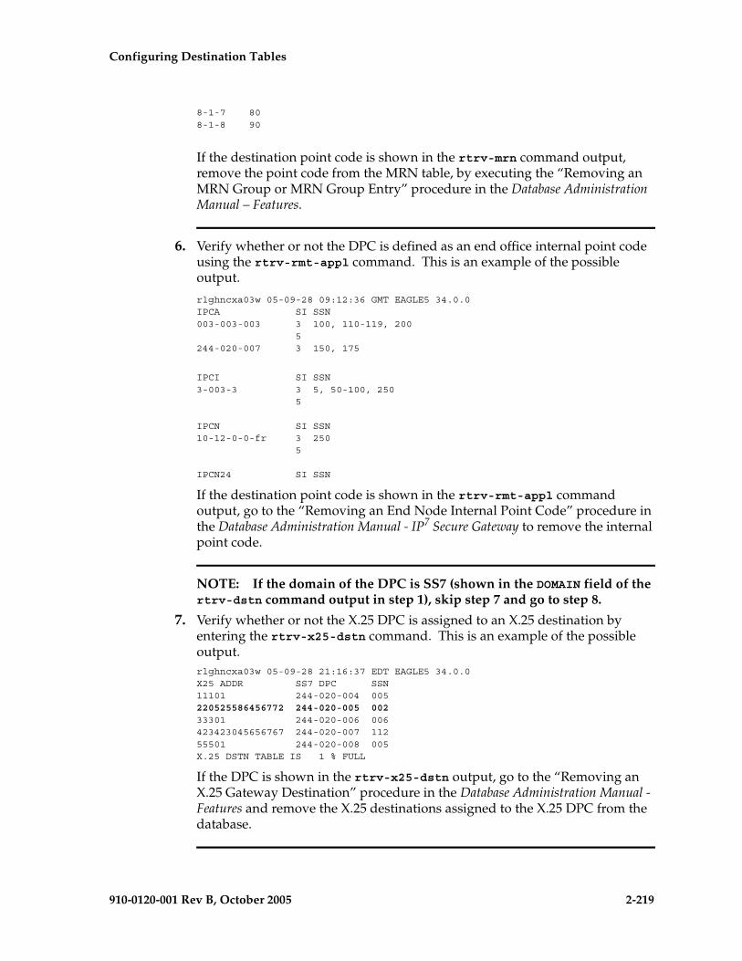
Configuring Destination Tables
910-0120-001 Rev B, October 2005 2-219
8-1-7 808-1-8 90
If the destination point code is shown in the rtrv-mrn command output, remove the point code from the MRN table, by executing the “Removing an MRN Group or MRN Group Entry” procedure in the Database Administration Manual – Features.
6. Verify whether or not the DPC is defined as an end office internal point code using the rtrv-rmt-appl command. This is an example of the possible output.
rlghncxa03w 05-09-28 09:12:36 GMT EAGLE5 34.0.0IPCA SI SSN003-003-003 3 100, 110-119, 200 5244-020-007 3 150, 175
IPCI SI SSN3-003-3 3 5, 50-100, 250 5
IPCN SI SSN10-12-0-0-fr 3 250 5
IPCN24 SI SSN
If the destination point code is shown in the rtrv-rmt-appl command output, go to the “Removing an End Node Internal Point Code” procedure in the Database Administration Manual - IP7 Secure Gateway to remove the internal point code.
NOTE: If the domain of the DPC is SS7 (shown in the DOMAIN field of the rtrv-dstn command output in step 1), skip step 7 and go to step 8.
7. Verify whether or not the X.25 DPC is assigned to an X.25 destination by entering the rtrv-x25-dstn command. This is an example of the possible output.rlghncxa03w 05-09-28 21:16:37 EDT EAGLE5 34.0.0X25 ADDR SS7 DPC SSN11101 244-020-004 005220525586456772 244-020-005 00233301 244-020-006 006423423045656767 244-020-007 11255501 244-020-008 005X.25 DSTN TABLE IS 1 % FULL
If the DPC is shown in the rtrv-x25-dstn output, go to the “Removing an X.25 Gateway Destination” procedure in the Database Administration Manual - Features and remove the X.25 destinations assigned to the X.25 DPC from the database.
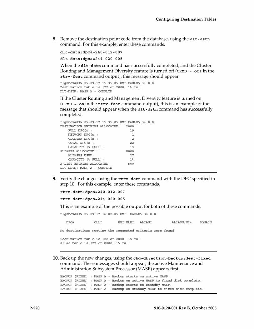
2-220 910-0120-001 Rev B, October 2005
Configuring Destination Tables
8. Remove the destination point code from the database, using the dlt-dstn command. For this example, enter these commands.
dlt-dstn:dpca=240-012-007
dlt-dstn:dpca=244-020-005
When the dlt-dstn command has successfully completed, and the Cluster Routing and Management Diversity feature is turned off (CRMD = off in the rtrv-feat command output), this message should appear.rlghncxa03w 05-09-17 15:35:05 GMT EAGLE5 34.0.0Destination table is (22 of 2000) 1% full DLT-DSTN: MASP A - COMPLTD
If the Cluster Routing and Management Diversity feature is turned on (CRMD = on in the rtrv-feat command output), this is an example of the message that should appear when the dlt-dstn command has successfully completed.
rlghncxa03w 05-09-17 15:35:05 GMT EAGLE5 34.0.0DESTINATION ENTRIES ALLOCATED: 2000 FULL DPC(s): 19 NETWORK DPC(s): 1 CLUSTER DPC(s): 2 TOTAL DPC(s): 22 CAPACITY (% FULL): 1%ALIASES ALLOCATED: 8000 ALIASES USED: 27 CAPACITY (% FULL): 1%X-LIST ENTRIES ALLOCATED: 500DLT-DSTN: MASP A - COMPLTD
9. Verify the changes using the rtrv-dstn command with the DPC specified in step 10. For this example, enter these commands.
rtrv-dstn:dpca=240-012-007
rtrv-dstn:dpca=244-020-005
This is an example of the possible output for both of these commands.
rlghncxa03w 05-09-17 16:02:05 GMT EAGLE5 34.0.0
DPCA CLLI BEI ELEI ALIASI ALIASN/N24 DOMAIN
No destinations meeting the requested criteria were found
Destination table is (22 of 2000) 1% fullAlias table is (27 of 8000) 1% full
10. Back up the new changes, using the chg-db:action=backup:dest=fixed command. These messages should appear; the active Maintenance and Administration Subsystem Processor (MASP) appears first.
BACKUP (FIXED) : MASP A - Backup starts on active MASP.BACKUP (FIXED) : MASP A - Backup on active MASP to fixed disk complete.BACKUP (FIXED) : MASP A - Backup starts on standby MASP.BACKUP (FIXED) : MASP A - Backup on standby MASP to fixed disk complete.

Configuring Destination Tables
910-0120-001 Rev B, October 2005 2-221
Flowchart 2-12. Removing a Destination Point Code (Sheet 1 of 5)
Enter thertrv-dstn command
To Sheet 3
Do you wish toremove an SPC?
Go to the "Changing aDestination Point Code"
procedure and change the SPC
What is the pointcode type of the DPC to
be removed?
Enter thertrv-ls command
No
Yes
ANSI
ITU-I
14-BitITU-N
Is the DPC to beremoved the DPC of a
route?
Go to the "Removing a Route"procedure to remove the
route
No
Yes
To Sheet 2
Enter thertrv-rte:dpcn24=<the
24-bit ITU-N destinationpoint code to be
removed from thedatabase> command
Enter thertrv-rte:dpci=<the
ITU-I destination pointcode to be removedfrom the database>
command
Enter thertrv-rte:dpca=<the
ANSI destination pointcode to be removedfrom the database>
command
24-BitITU-N
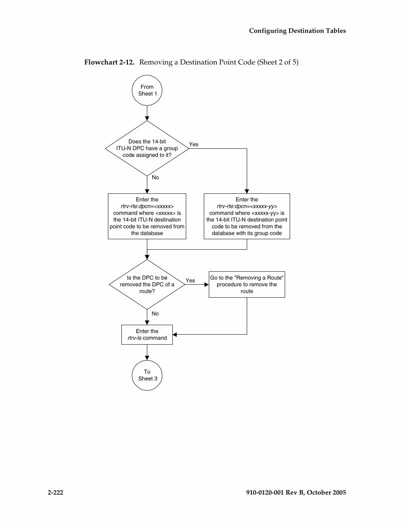
2-222 910-0120-001 Rev B, October 2005
Configuring Destination Tables
Flowchart 2-12. Removing a Destination Point Code (Sheet 2 of 5)
To Sheet 3
Enter thertrv-rte:dpcn=<xxxxx>
command where <xxxxx> isthe 14-bit ITU-N destination
point code to be removed fromthe database
Enter thertrv-rte:dpcn=<xxxxx-yy>
command where <xxxxx-yy> isthe 14-bit ITU-N destination point
code to be removed from thedatabase with its group code
Does the 14-bitITU-N DPC have a group
code assigned to it?
Enter thertrv-ls command
No
Yes
Is the DPC to beremoved the DPC of a
route?
Go to the "Removing a Route"procedure to remove the
route
No
Yes
From Sheet 1

Configuring Destination Tables
910-0120-001 Rev B, October 2005 2-223
Flowchart 2-12. Removing a Destination Point Code (Sheet 3 of 5)

2-224 910-0120-001 Rev B, October 2005
Configuring Destination Tables
Flowchart 2-12. Removing a Destination Point Code (Sheet 4 of 5)
Enter thechg-db:action=backup:dest=fixed
command
From Sheet 3
Is the domainof the DPC X.25 or
SS7?
X.25
SS7Enter the
dlt-dstn command with the DPCbeing removed with one of these
parameters::dpc/dpca=<ANSI DPC>
:dpci=<ITU-I DPC>:dpcn=<14-bit ITU-N DPC>
:dpcn24=<24-bit ITU-N DPC>
To Sheet 5
Enter thertrv-mrn command
Is the DPCin the mated relay
node table?
Go to the "Removing an MRNGroup or MRN Group Entry"procedure in the Database
Administration Manual - Featuresand remove the DPC from mated
relay node table
Yes
No
Is the IGTTLSfeature on?
Yes
No
Enter thertrv-rmt-appl command
Is the DPCin the rtrv-rmt-appl
output?
Go to the "Removing an End NodeInternal Point Code" procedure in
the Database AdministrationManual - IP7 Secure Gateway, andremove the DPC the internal point
code
Yes
No
Enter thertrv-dstn command with the DPCspecified in the dlt-dstn command
with one of these parameters::dpc/dpca=<ANSI DPC>
:dpci=<ITU-I DPC>:dpcn=<14-bit ITU-N DPC>
:dpcn24=<24-bit ITU-N DPC>

Configuring Destination Tables
910-0120-001 Rev B, October 2005 2-225
Flowchart 2-12. Removing a Destination Point Code (Sheet 5 of 5)
Go to the "Removing an X.25 GatewayDestination" procedure in the
Database Administration Manual -Features and remove the X.25
destination
Enter thechg-db:action=backup:dest=fixed
command
From Sheet 4
Enter thertrv-x25-dstn command
is the DPCassigned to an X.25
destination?
No
Yes
Enter thedlt-dstn command with the
DPC being removed with thisparameter:
:dpc/dpca=<ANSI DPC>
Enter thertrv-dstn command with theDPC specified in the dlt-dstn
command with this parameter::dpc/dpca=<ANSI DPC>

2-226 910-0120-001 Rev B, October 2005
Configuring Destination Tables
Changing a Destination Point Code
This procedure is used to change the attributes of a full destination point code in the database, using the chg-dstn command.
To change the attributes of a cluster point code, go to the “Changing the Attributes of a Cluster Point Code” procedure on page 2-161.
This procedure cannot be used to change a true point code (dpc/dpca/dpci/dpcn/dpcn24) or the domain of a destination point code. To change a true point code or the domain of a destination point code, the destination point code must be removed, then re-entered. Go to the “Removing a Destination Point Code” procedure on page 2-214 and remove the point code from the database. To add the new point code, go to one of these procedures:
• Cluster point code – “Adding a Cluster Point Code” procedure on page 2-142
• Network routing point code – “Adding a Network Routing Point Code” procedure on page 2-181
• All other point codes – “Adding a Destination Point Code” procedure on page 2-191
The destination point code to be changed must be in the database.
The chg-dstn command uses these parameters:
:dpc/dpca/dpci/dpcn/dpcn24 – The destination point code in the database being changed
:aliasa/aliasi/aliasn/aliasn24 – The alternate destination point code. Two optional alias addresses can be defined.
NOTE: If 7000 or 8000 routesets are enabled, the EAGLE 5 SAS can contain a maximum of 8000 alias point codes. If 7000 or 8000 routesets are not enabled, the EAGLE 5 SAS can contain a maximum of 12000 alias point codes.
NOTE: See “Point Code Formats” on page 2-4 for a definition of the point code types that are used on the EAGLE 5 SAS and for a definition of the different formats that can be used for ITU national point codes. A private point code cannot be used as an alias point code.
:clli – The Common Language Location Identifier assigned to this point code
:bei – Broadcast exception indicator that indicates whether transfer-prohibited (TFP) messages will be broadcast from this node. The bei=yes parameter means TFPs will not be broadcast. The bei=no parameter means TFPs will be broadcast.
:spc/spca/spci/spcn/spcn24 – The secondary point code as defined by the ent-spc command. The secondary point code allows the EAGLE 5 SAS to use another point code in addition to the one defined by the dpc, dpca, dpci, dpcn, or dpcn24 parameters of the chg-dstn command for SS7 routing

Configuring Destination Tables
910-0120-001 Rev B, October 2005 2-227
purposes. See the “Multiple Point Code Support” section on page 2-55 for more information on secondary point codes. A private point code cannot be used as a secondary point code.
:elei – For cluster point codes only. Specifies whether or not the EAGLE 5 SAS maintains a dynamic status exception list for each cluster route that may be used to reach the member signaling points making up the cluster.
NOTE: See the “Cluster Routing and Management Diversity (CRMD)” section on page 2-119 for more information on the cluster routing feature.
For more information on changing the value of the elei parameter, see the “Changing the Attributes of a Cluster Point Code” procedure on page 2-161.
:ncai – The nested cluster allowed indicator specifies whether or not the route to the cluster point code can be different from the route to a point code that is a member of the cluster point code.
NOTE: See the “Nested Cluster Routing” section on page 2-135 for more information on the nested cluster routing feature.
For more information on changing the value of the ncai parameter, see the “Changing the Attributes of a Cluster Point Code” procedure on page 2-161.
Secondary point codes must be in the SS7 domain and must be a full point code. A secondary point code can only be assigned to a full point code in the SS7 domain. The network type of the secondary point code must match the network type of the destination point code. The secondary point code used in this procedure must be configured in the database with the ent-spc command. The secondary point codes are shown in the SPCA, SPC-I, SPC-N, and SPC-N24 fields of the rtrv-spc command output. If the desired secondary point code is not shown in the output of the rtrv-spc command, go to the “Adding a Secondary Point Code” procedure on page 2-63 and configure the desired point code as a secondary point code.
If a secondary point code is assigned to the destination point code, the group code of the 14-bit ITU-N destination point code must match the group code of the secondary point code. Otherwise, the group code of the destination point code must match the group code assigned to the EAGLE 5 SAS’s true 14-bit ITU-N point code, shown in the PCN field of the rtrv-sid output.
The value none for the spca, spci, spcn, or spcn24 parameters removes the assignment of the current secondary point code and leaves the destination point code without a secondary point code.
The value none for the aliasa (ANIS), aliasi (ITU-I), aliasn (14-bit ITU-N), or aliasn24 (24-bit ITU-N) parameters removes that type of alias point code from the destination point code.
2-228 910-0120-001 Rev B, October 2005
Configuring Destination Tables
The value of the clli parameter cannot be in the destination point code table and cannot match the CLLI of the EAGLE 5 SAS. Verify this by entering the rtrv-dstn and the rtrv-sid commands, shown in steps 1 and 2 of the procedure that follows. If the value of the clli parameter matches any CLLI values in either of these outputs, choose another value for the clli parameter that does not match any CLLIs shown in either of these command outputs.
If the dpci, dpcn, dpcn24, aliasa, aliasi, aliasn, aliasn24, spca, spci, spcn, or spcn24 parameters cannot be specified if the existing domain of the destination point code being changed is X.25 (domain=x25).
To enter point codes of any network type (ANSI, ITU-I, or ITU-N - 14-bit or 24-bit) into the database with the chg-dstn command, the self ID of the EAGLE 5 SAS must be defined for these networks. Verify this with the rtrv-sid command.
If a point code value is shown in the PCA field of the rtrv-sid command, then ANSI point codes can be specified with the chg-dstn command.
If a point code value is shown in the PCI field of the output of the rtrv-sid command, then ITU-I point codes can be specified with the chg-dstn command. The PCI column of the rtrv-sid output can contain spare and non-spare point code values. To provision ITU-I non-spare point codes in this procedure, the rtrv-sid output must contain an ITU-I non-spare point code in the PCI column. To provision ITU-I spare point codes in this procedure, the rtrv-sid output must contain an ITU-I spare point code in the PCI column.
If a point code value is shown in the PCN field of the output of the rtrv-sid command, then 14-bit ITU-N point codes can be specified with the chg-dstn command. The PCN column of the rtrv-sid output can contain spare and non-spare point code values. To provision 14-bit ITU-N non-spare point codes in this procedure, the rtrv-sid output must contain a 14-bit ITU-N non-spare point code in the PCN column. To provision 14-bit ITU-N spare point codes in this procedure, the rtrv-sid output must contain a 14-bit ITU-N spare point code in the PCN column.
If a point code value is shown in the PCN24 field of the output of the rtrv-sid command, then 24-bit ITU-N point codes can be specified with the chg-dstn command.
If no values are shown in the PCA, PCI, PCN, or PCN24 fields in the rtrv-sid command output, the self-identification of the EAGLE 5 SAS must be updated with an ANSI point code, ITU international point code or a 14-bit ITU national point code. Go to “Changing the Self-Identification of the EAGLE 5 SAS” procedure on page 2-90 to change the self-identification of the EAGLE 5 SAS.
NOTE: The EAGLE 5 SAS can contain 14-bit ITU national point codes or 24-bit ITU national point codes, but both at the same time.
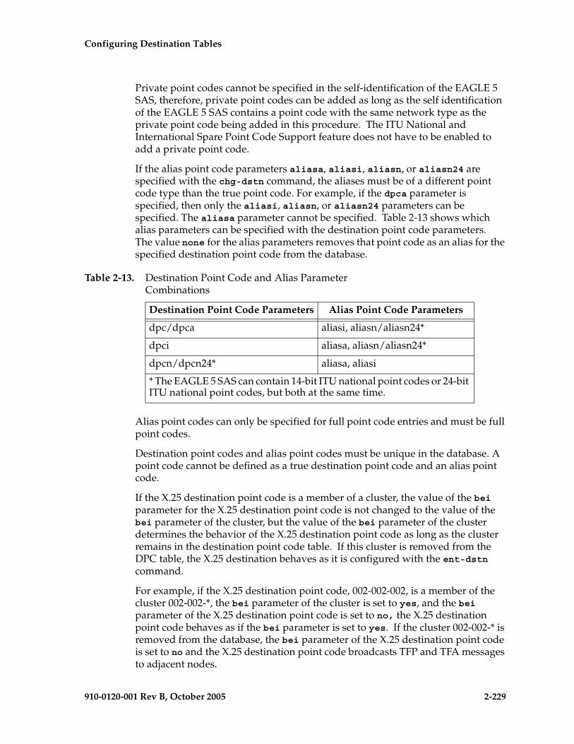
Configuring Destination Tables
910-0120-001 Rev B, October 2005 2-229
Private point codes cannot be specified in the self-identification of the EAGLE 5 SAS, therefore, private point codes can be added as long as the self identification of the EAGLE 5 SAS contains a point code with the same network type as the private point code being added in this procedure. The ITU National and International Spare Point Code Support feature does not have to be enabled to add a private point code.
If the alias point code parameters aliasa, aliasi, aliasn, or aliasn24 are specified with the chg-dstn command, the aliases must be of a different point code type than the true point code. For example, if the dpca parameter is specified, then only the aliasi, aliasn, or aliasn24 parameters can be specified. The aliasa parameter cannot be specified. Table 2-13 shows which alias parameters can be specified with the destination point code parameters. The value none for the alias parameters removes that point code as an alias for the specified destination point code from the database.
Alias point codes can only be specified for full point code entries and must be full point codes.
Destination point codes and alias point codes must be unique in the database. A point code cannot be defined as a true destination point code and an alias point code.
If the X.25 destination point code is a member of a cluster, the value of the bei parameter for the X.25 destination point code is not changed to the value of the bei parameter of the cluster, but the value of the bei parameter of the cluster determines the behavior of the X.25 destination point code as long as the cluster remains in the destination point code table. If this cluster is removed from the DPC table, the X.25 destination behaves as it is configured with the ent-dstn command.
For example, if the X.25 destination point code, 002-002-002, is a member of the cluster 002-002-*, the bei parameter of the cluster is set to yes, and the bei parameter of the X.25 destination point code is set to no, the X.25 destination point code behaves as if the bei parameter is set to yes. If the cluster 002-002-* is removed from the database, the bei parameter of the X.25 destination point code is set to no and the X.25 destination point code broadcasts TFP and TFA messages to adjacent nodes.
Table 2-13. Destination Point Code and Alias Parameter Combinations
Destination Point Code Parameters Alias Point Code Parameters
dpc/dpca aliasi, aliasn/aliasn24*
dpci aliasa, aliasn/aliasn24*
dpcn/dpcn24* aliasa, aliasi
* The EAGLE 5 SAS can contain 14-bit ITU national point codes or 24-bit ITU national point codes, but both at the same time.

2-230 910-0120-001 Rev B, October 2005
Configuring Destination Tables
If you intend to use this X.25 destination point code with an X.25 route that has the lc2nm parameter set to yes, make sure that the bei parameter of the cluster containing the X.25 destination point code is set to no. Verify the value of the bei parameter of the cluster with the rtrv-dstn command. To change the existing value the bei parameter, specify the bei parameter with the appropriate value (yes or no) with the chg-dstn command in this procedure. If the bei parameter is not specified with the chg-dstn command, the value of the bei parameter is not changed.
If either the dpcn or aliasn parameters are specified with the chg-dstn command, the format of the 14-bit ITU-N point code values must match the format shown in the NPCFMTI field of the rtrv-stpopts command output. For more information, see “14-Bit ITU National Point Code Formats” on page 2-10.
The examples in this procedure are used to change the attributes of the destination point code 240-012-007. The format of the 14-bit ITU national point codes used in these examples is 4-4-4-2.
Canceling the RTRV-DSTN Command
Because the rtrv-dstn command used in this procedure can output information for a long period of time, the rtrv-dstn command can be canceled and the output to the terminal stopped. There are three ways that the rtrv-dstn command can be canceled:
• Press the F9 function key on the keyboard at the terminal where the rtrv-dstn command was entered
• Enter the canc-cmd without the trm parameter at the terminal where the rtrv-dstn command was entered
• Enter the canc-cmd:trm=<xx>, where <xx> is the terminal where the rtrv-dstn command was entered, from another terminal other than the terminal where the rtrv-dstn command was entered. To enter the canc-cmd:trm=<xx> command, the terminal must allow Security Administration commands to be entered from it and the user must be allowed to enter Security Administration commands. The terminal’s permissions can be verified with the rtrv-secu-trm command. The user’s permissions can be verified with the rtrv-user or rtrv-secu-user commands.
For more information about the canc-cmd command, refer to the Commands Manual.
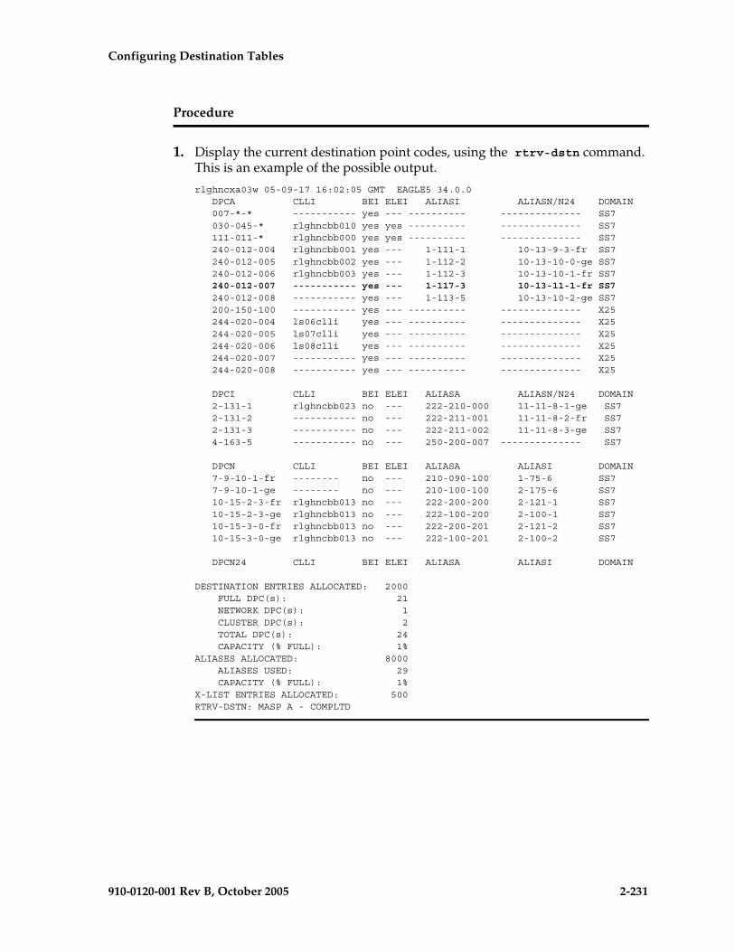
Configuring Destination Tables
910-0120-001 Rev B, October 2005 2-231
Procedure
1. Display the current destination point codes, using the rtrv-dstn command. This is an example of the possible output.
rlghncxa03w 05-09-17 16:02:05 GMT EAGLE5 34.0.0 DPCA CLLI BEI ELEI ALIASI ALIASN/N24 DOMAIN 007-*-* ----------- yes --- ---------- -------------- SS7 030-045-* rlghncbb010 yes yes ---------- -------------- SS7 111-011-* rlghncbb000 yes yes ---------- -------------- SS7 240-012-004 rlghncbb001 yes --- 1-111-1 10-13-9-3-fr SS7 240-012-005 rlghncbb002 yes --- 1-112-2 10-13-10-0-ge SS7 240-012-006 rlghncbb003 yes --- 1-112-3 10-13-10-1-fr SS7 240-012-007 ----------- yes --- 1-117-3 10-13-11-1-fr SS7 240-012-008 ----------- yes --- 1-113-5 10-13-10-2-ge SS7 200-150-100 ----------- yes --- ---------- -------------- X25 244-020-004 ls06clli yes --- ---------- -------------- X25 244-020-005 ls07clli yes --- ---------- -------------- X25 244-020-006 ls08clli yes --- ---------- -------------- X25 244-020-007 ----------- yes --- ---------- -------------- X25 244-020-008 ----------- yes --- ---------- -------------- X25
DPCI CLLI BEI ELEI ALIASA ALIASN/N24 DOMAIN 2-131-1 rlghncbb023 no --- 222-210-000 11-11-8-1-ge SS7 2-131-2 ----------- no --- 222-211-001 11-11-8-2-fr SS7 2-131-3 ----------- no --- 222-211-002 11-11-8-3-ge SS7 4-163-5 ----------- no --- 250-200-007 -------------- SS7
DPCN CLLI BEI ELEI ALIASA ALIASI DOMAIN 7-9-10-1-fr -------- no --- 210-090-100 1-75-6 SS7 7-9-10-1-ge -------- no --- 210-100-100 2-175-6 SS7 10-15-2-3-fr rlghncbb013 no --- 222-200-200 2-121-1 SS7 10-15-2-3-ge rlghncbb013 no --- 222-100-200 2-100-1 SS7 10-15-3-0-fr rlghncbb013 no --- 222-200-201 2-121-2 SS7 10-15-3-0-ge rlghncbb013 no --- 222-100-201 2-100-2 SS7
DPCN24 CLLI BEI ELEI ALIASA ALIASI DOMAIN
DESTINATION ENTRIES ALLOCATED: 2000 FULL DPC(s): 21 NETWORK DPC(s): 1 CLUSTER DPC(s): 2 TOTAL DPC(s): 24 CAPACITY (% FULL): 1%ALIASES ALLOCATED: 8000 ALIASES USED: 29 CAPACITY (% FULL): 1%X-LIST ENTRIES ALLOCATED: 500RTRV-DSTN: MASP A - COMPLTD

2-232 910-0120-001 Rev B, October 2005
Configuring Destination Tables
NOTE: If the CLLI value assigned to the destination point code is not being changed, skip this step and go to step 3.
2. Display the EAGLE 5 SAS self-identification, using the rtrv-sid command. This is an example of the possible output.
rlghncxa03w 05-09-10 11:43:04 GMT EAGLE5 34.0.0 PCA PCI PCN CLLI PCTYPE 100-100-100 3-75-7 7-9-8-1-fr rlghncxa03w OTHER
CPCA 002-002-002 002-002-003 002-002-004 002-002-005 002-002-006 002-002-007 002-002-008 002-002-009 004-002-001 004-003-003 050-060-070
CPCA (LNP) 005-005-002 005-005-004 005-005-005
CPCI 1-002-1 1-002-2 1-002-3 1-002-4 2-001-1 7-222-7
CPCN 2-0-10-3-fr 2-0-11-0-fr 2-0-11-2-fr 2-0-12-1-fr 2-2-3-3-fr 2-2-4-0-fr 10-14-10-1-fr
If the CLLI value for the destination point code is being changed in this procedure, that CLLI value cannot be shown in the CLLI fields of either the rtrv-dstn (step 1) or the rtrv-sid (step 2) command outputs.
NOTE: If the point code being changed in this procedure is an X.25 point code, skip steps 3 through 9, and go to step 10.
NOTE: If the secondary point code value assigned to the destination point code is not being changed, skip this step and step 4, and go to step 5.
3. Display all the attributes of the point code being changed, using the rtrv-dstn command with either the dpca, dpci, dpcn, or dpcn24 parameters.
For this example, enter this command.
rtrv-dstn:dpca=240-012-007
This is an example of the possible output.
rlghncxa03w 05-09-28 21:16:37 GMT EAGLE5 34.0.0 DPCA CLLI BEI ELEI ALIASI ALIASN/N24 DOMAIN 240-012-007 ----------- yes --- 1-117-3 10-13-11-1-fr SS7
SPC NCAI 003-010-010 no
DESTINATION ENTRIES ALLOCATED: 2000 FULL DPC(s): 21 NETWORK DPC(s): 1 CLUSTER DPC(s): 2 TOTAL DPC(s): 24 CAPACITY (% FULL): 1%ALIASES ALLOCATED: 8000 ALIASES USED: 29

Configuring Destination Tables
910-0120-001 Rev B, October 2005 2-233
CAPACITY (% FULL): 1%X-LIST ENTRIES ALLOCATED: 500RTRV-DSTN: MASP A - COMPLTD
The secondary point code being changed is shown in the SPC field.
4. Display the secondary point codes in the database with the rtrv-spc command. This is an example of the possible output.
rlghncxa03w 05-09-17 16:02:05 GMT EAGLE5 34.0.0SPC (Secondary Point Codes)
SPCA 001-010-010 002-010-010 003-010-010 010-100-010
SPC-I 1-253-5 2-254-6 3-255-7 4-100-1
SPC-N 10-1-11-1-ge 13-2-12-0-ge 14-15-12-1-ge
SPC-N24
none
Secondary Point Code table is (11 of 40) 28% full
If the desired secondary point code is not shown in the rtrv-spc command output, go to the “Adding a Secondary Point Code” procedure on page 2-63 and add the secondary point code to the database.
NOTE: If an existing alias point code is not being changed in this procedure, or if a new alias point code is not being added in this procedure, skip steps 5 through 9, and go to step 10.
NOTE: If an ITU national alias point code (aliasn parameter) is not being changed in this procedure, skip steps 5 and 6, and go to step 7.
5. Display the existing values for the npcfmti parameter by entering the rtrv-stpopts command. The value for the npcfmti parameter is shown in the NPCFMTI field. This is an example of the possible output.
rlghncxa03w 05-09-17 16:02:05 GMT EAGLE5 34.0.0STP OPTIONS-----------------------NPCFMTI 4-4-4-2
NOTE: The rtrv-stpopts command output contains other fields that are not used by this procedure. If you wish to see all the fields displayed by the rtrv-stpopts command, see the rtrv-stpopts command description in the Commands Manual.

2-234 910-0120-001 Rev B, October 2005
Configuring Destination Tables
If you wish to change the format of the 14-bit ITU national point codes, go to “14-Bit ITU National Point Code Formats” section on page 2-10. Changing the formats of the 14-bit ITU national point codes will change how all existing 14-bit ITU national point codes are displayed in the database.
NOTE: If the current 14-bit ITU-N alias point code being changed does not have a group code assigned to it, skip step 6 and go to step 7.
NOTE: If the group code being assigned to the new 14-bit ITU-N alias point code is shown in the rtrv-dstn output in step 1, skip step 6 and go to step 7.
6. The group code to be assigned to the 14-bit ITU-N alias point code must be shown in either the rtrv-sid or rtrv-spc outputs. If step 2 (rtrv-sid command) was performed in this procedure, and the desired group code is shown in step 2, go to step 7.
If step 2 was not performed in this procedure, enter the rtrv-sid command. See step 2 for an example of the output. If the desired group code is shown in the rtrv-sid output, go to step 7.
If the desired group code is not shown in the rtrv-sid output, verify the group codes in the rtrv-spc output.
If step 4 (rtrv-spc command) was performed in this procedure, and the desired group code is shown in step 4, go to step 7.
If step 4 was not performed in this procedure, enter the rtrv-spc command. See step 4 for an example of the output. If the desired group code is shown in the rtrv-spc output, go to step 7.
If the desired group code is not shown in the rtrv-spc output, add a secondary point code with the desired group code by performing the “Adding a Point Code to the Self-Identification of the EAGLE 5 SAS” procedure on page 2-81.
NOTE: If new alias point codes are not being added in this procedure, skip steps 7, 8, and 9, and go to step 10.
NOTE: If the DPC quantity shown in the rtrv-dstn output in step 1 is from 6001 to 8000, skip step 7 and go to step 8.
7. Verify that either 6000, 7000, or 8000 routesets are enabled by entering the rtrv-ctrl-feat command. The following is an example of the possible output.
rlghncxa03w 05-09-28 21:15:37 GMT EAGLE5 34.0.0The following features have been permanently enabled:
Feature Name Partnum Status QuantityIPGWx Signaling TPS 893012814 on 20000ISUP Normalization 893000201 on ----Command Class Management 893005801 on ----LNP Short Message Service 893006601 on ----Intermed GTT Load Sharing 893006901 on ----
Configuring Destination Tables
910-0120-001 Rev B, October 2005 2-235
XGTT Table Expansion 893006101 on 4000000XMAP Table Expansion 893007710 on 3000Large System # Links 893005901 on 1500Routesets 893006401 on 6000HC-MIM SLK Capacity 893012707 on 64
The following features have been temporarily enabled:
Feature Name Partnum Status Quantity Trial Period LeftZero entries found.
The following features have expired temporary keys:
Feature Name PartnumZero entries found.
8. The number of routesets enabled are shown in the rtrv-ctrl-feat output in step 7 with the quantity of 6000, 7000, or 8000 in the Routesets row. If 6000, 7000, or 8000 routesets are not enabled, the EAGLE 5 SAS can contain a maximum or either 2000 or 5000 routesets. The routeset quantity enabled is also shown by the DPC quantity in the rtrv-dstn output in step 1. If the DPC quantity is from 6001 to 8000, either 7000 or 8000 routesets have been enabled.
If 7000 or 8000 routesets are enabled, the EAGLE 5 SAS can contain a maximum of 8000 alias point codes. If 7000 or 8000 routesets are not enabled, the EAGLE 5 SAS can contain a maximum of 12000 alias point codes.
If the alias point code being added will exceed the maximum number of alias point codes the EAGLE 5 SAS is allowed to have, other alias point codes will have to be removed before this alias point code can be added.
To remove an alias point code, enter the chg-dstn command with the DPC containing the alias point code being removed, and with the value none for the aliasa/aliasi/aliasn/aliasn24 parameter. For this example, enter this command.
chg-dstn:dpcn=10-15-2-3-fr:aliasa=none:aliasi=none
When this command has successfully completed, and the Cluster Routing and Management Diversity feature is turned off (CRMD = off in the rtrv-feat command output), this message should appear.
rlghncxa03w 05-09-17 15:35:05 GMT EAGLE5 34.0.0Destination table is (24 of 2000) 1% fullAlias table is (29 of 8000) 1% fullCHG-DSTN: MASP A - COMPLTD
If the Cluster Routing and Management Diversity feature is turned on (CRMD = on in the rtrv-feat command output), this message should appear when each command has successfully completed.
rlghncxa03w 05-09-17 15:35:05 GMT EAGLE5 34.0.0DESTINATION ENTRIES ALLOCATED: 2000 FULL DPC(s): 21 NETWORK DPC(s): 1 CLUSTER DPC(s): 2 TOTAL DPC(s): 24

2-236 910-0120-001 Rev B, October 2005
Configuring Destination Tables
CAPACITY (% FULL): 1%ALIASES ALLOCATED: 8000 ALIASES USED: 29 CAPACITY (% FULL): 1%X-LIST ENTRIES ALLOCATED: 500CHG-DSTN: MASP A - COMPLTD
When the chg-dstn command has successfully completed, go to step 8 to add the new alias point code.
If you do not wish to remove other alias point codes, do not perform the chg-dstn command to remove the alias point code. Go to step 9 and change the destination point code without adding an alias point code.
If the alias point code being added will not exceed the maximum number of alias point codes the EAGLE 5 SAS is allowed to have, go to step 9 and change the destination point code and add the new alias point code.
NOTE: If the rtrv-dstn command output in step 1 shows point codes of the same type as the new alias point code you wish to assign to the destination point code being changed in this procedure, skip step 9 and go to step 10.
ANSI point codes are shown in the DPCA and ALIASA fields. ITU-I or ITU-I Spare point codes are shown in the DPCI and ALIASI fields. 14-bit ITU-N or 14-bit ITU-N Spare point codes are shown in the DPCN and ALIASN/24 fields. 24-bit ITU-N point codes are shown in the DPCN24 and ALIASN/24 fields. The EAGLE 5 SAS can contain either 14-bit ITU-N or 24-bit ITU-N point codes, but not both types of point codes at the same time.
9. The EAGLE 5 SAS must contain point codes with the same network type as the new alias point code being assigned to the destination point code being changed in this procedure. For example, if the new alias point code is an ITU international point code, then ITU international point codes must be shown in the rtrv-sid output.
If steps 2 or 6 (rtrv-sid command) were performed in this procedure, and a point code of the same type as the new alias point code is shown in the rtrv-sid output (see step 2 for an example of the output), go to step 10.
If step 2 was not performed in this procedure, enter the rtrv-sid command. See step 2 for an example of the output. If a point code of the same type as the new alias point code is shown in the rtrv-sid output, go to step 10.
To enter an ANSI alias point code, a ANSI point code must be shown in the PCA field of the rtrv-sid output.
To enter an ITU-I non-spare alias point code, an ITU-I non-spare point code must be shown in the PCI field of the rtrv-sid output.
To enter an ITU-I spare alias point code, an ITU-I spare point code must be shown in the PCI field of the rtrv-sid output.
Configuring Destination Tables
910-0120-001 Rev B, October 2005 2-237
To enter a 14-bit ITU-N non-spare alias point code, a 14-bit non-spare point code must be shown in the PCN field of the rtrv-sid output. To enter a 14-bit ITU-N spare alias point code, a 14-bit ITU-N spare point code must be shown in the PCN field of the rtrv-sid output. If 14-bit ITU-N alias point codes (spare or non-spare point codes) with group codes are being provisioned in this procedure, the point code value in the PCN field must have a group code assigned to it.
To enter a 24-bit ITU-N alias point code, a 24-bit ITU-N point code must be shown in the PCN24 field of the rtrv-sid output.
If a point code of the same type as the new alias point code is not shown in the rtrv-sid output, add a point code of the same network type as the new alias point code by performing the “Adding a Point Code to the Self-Identification of the EAGLE 5 SAS” procedure on page 2-81.
10. Change the destination point code, using the chg-dstn command. For this example, enter this command.
chg-dstn:dpca=240-012-007:clli=ls09clli:bei=no:aliasi=2-66-1:aliasn=0-10-13-3-fr:spca=003-010-010
If the destination point code being changed is an X.25 destination point code, only the bei and clli parameters can be specified with the chg-dstn command.
If the aliasn parameter is specified with the chg-dstn command, make sure that the format of the ITU national alias point code matches the format shown in the NPCFMTI field of the rtrv-stpopts command output shown in step 5.
When this command has successfully completed, and the Cluster Routing and Management Diversity feature is turned off (CRMD = off in the rtrv-feat command output), this message should appear.
rlghncxa03w 05-09-17 15:35:05 GMT EAGLE5 34.0.0Destination table is (24 of 2000) 1% fullAlias table is (29 of 8000) 1% fullCHG-DSTN: MASP A - COMPLTD
If the Cluster Routing and Management Diversity feature is turned on (CRMD = on in the rtrv-feat command output), this message should appear when each command has successfully completed.
rlghncxa03w 05-09-17 15:35:05 GMT EAGLE5 34.0.0DESTINATION ENTRIES ALLOCATED: 2000 FULL DPC(s): 21 NETWORK DPC(s): 1 CLUSTER DPC(s): 2 TOTAL DPC(s): 24 CAPACITY (% FULL): 1%ALIASES ALLOCATED: 8000 ALIASES USED: 29 CAPACITY (% FULL): 1%X-LIST ENTRIES ALLOCATED: 500CHG-DSTN: MASP A - COMPLTD

2-238 910-0120-001 Rev B, October 2005
Configuring Destination Tables
11. Verify the changes using the rtrv-dstn command, and specifying the destination point code that was entered in step 10.
• If an ANSI destination point code was changed in step 10, use the dpca parameter to display the attributes of the destination point code.
• If an ITU international destination point code was changed in step 10, use the dpci parameter to display the attributes of the destination point code.
• If a 14-bit ITU national destination point code was changed in step 10, use the dpcn parameter to display the attributes of the destination point code.
• If a 24-bit ITU national destination point code was changed in step 10, use the dpcn24 parameter to display the attributes of the destination point code.
For this example, enter this command.
rtrv-dstn:dpca=240-012-007
This is an example of the possible output.
rlghncxa03w 05-09-28 21:16:37 GMT EAGLE5 34.0.0 DPCA CLLI BEI ELEI ALIASI ALIASN/N24 DOMAIN 240-012-007 ls09clli no --- 2-66-1 0-10-13-3-fr SS7
SPC NCAI 003-010-010 no
DESTINATION ENTRIES ALLOCATED: 2000 FULL DPC(s): 21 NETWORK DPC(s): 1 CLUSTER DPC(s): 2 TOTAL DPC(s): 24 CAPACITY (% FULL): 1%ALIASES ALLOCATED: 8000 ALIASES USED: 29 CAPACITY (% FULL): 1%X-LIST ENTRIES ALLOCATED: 500RTRV-DSTN: MASP A - COMPLTD
12. Back up the new changes, using the chg-db:action=backup:dest=fixed command. These messages should appear; the active Maintenance and Administration Subsystem Processor (MASP) appears first.
BACKUP (FIXED) : MASP A - Backup starts on active MASP.BACKUP (FIXED) : MASP A - Backup on active MASP to fixed disk complete.BACKUP (FIXED) : MASP A - Backup starts on standby MASP.BACKUP (FIXED) : MASP A - Backup on standby MASP to fixed disk complete.

Configuring Destination Tables
910-0120-001 Rev B, October 2005 2-239
Flowchart 2-13. Changing a Destination Point Code (Sheet 1 of 9)

2-240 910-0120-001 Rev B, October 2005
Configuring Destination Tables
Flowchart 2-13. Changing a Destination Point Code (Sheet 2 of 9)

Configuring Destination Tables
910-0120-001 Rev B, October 2005 2-241
Flowchart 2-13. Changing a Destination Point Code (Sheet 3 of 9)

2-242 910-0120-001 Rev B, October 2005
Configuring Destination Tables
Flowchart 2-13. Changing a Destination Point Code (Sheet 4 of 9)
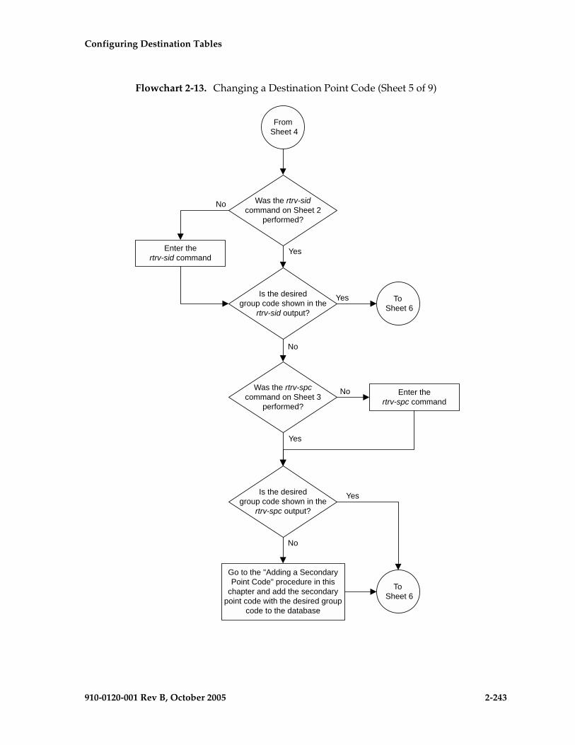
Configuring Destination Tables
910-0120-001 Rev B, October 2005 2-243
Flowchart 2-13. Changing a Destination Point Code (Sheet 5 of 9)
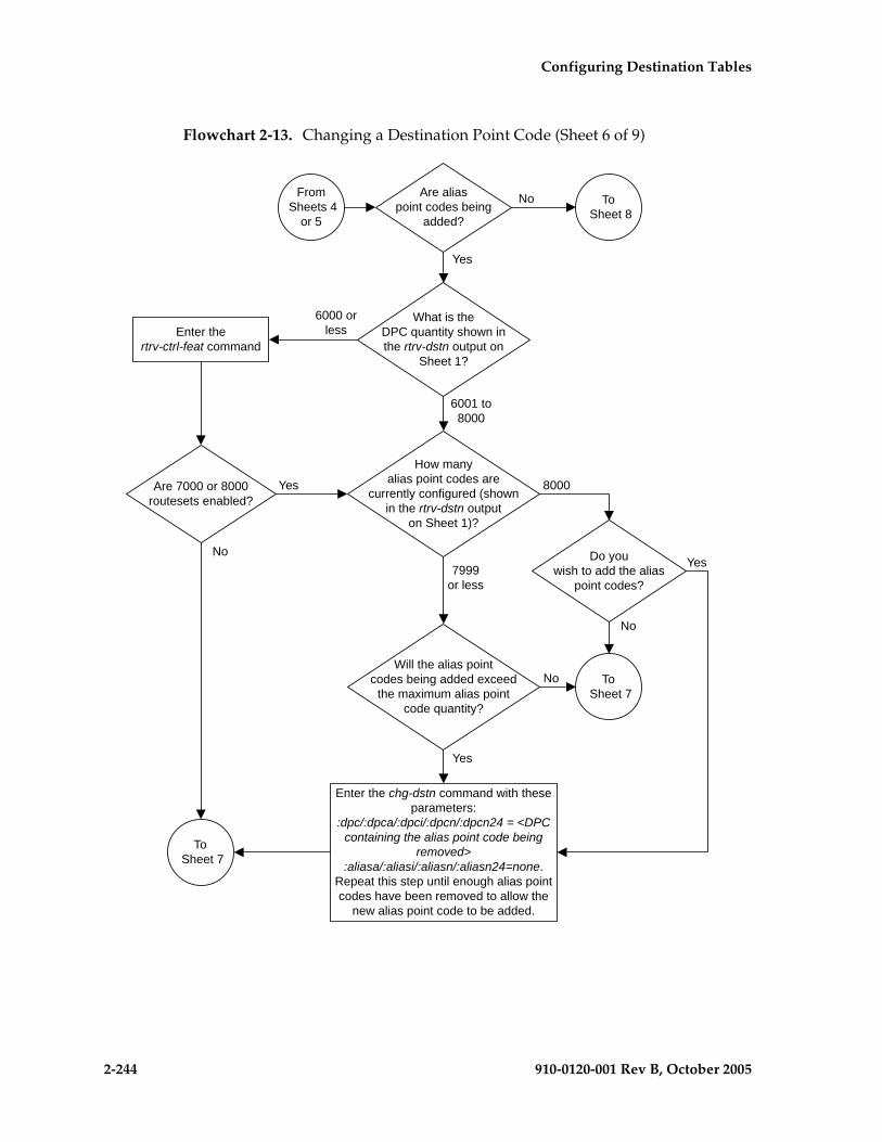
2-244 910-0120-001 Rev B, October 2005
Configuring Destination Tables
Flowchart 2-13. Changing a Destination Point Code (Sheet 6 of 9)

Configuring Destination Tables
910-0120-001 Rev B, October 2005 2-245
Flowchart 2-13. Changing a Destination Point Code (Sheet 7 of 9)

2-246 910-0120-001 Rev B, October 2005
Configuring Destination Tables
Flowchart 2-13. Changing a Destination Point Code (Sheet 8 of 9)

Configuring Destination Tables
910-0120-001 Rev B, October 2005 2-247
Flowchart 2-13. Changing a Destination Point Code (Sheet 9 of 9)

2-248 910-0120-001 Rev B, October 2005
Configuring Destination Tables
Changing the Group Code Assigned to a 14-Bit ITU National Point Code
This procedure is used to change the group code that is assigned to a 14-bit ITU national point code. The 14-bit ITU national point code to be changed must be in the database.
To change a group code assigned to a ITU national point code, a duplicate point code with the new group code must be configured in the database with a route, linkset, and signaling link to the new destination. Then the 14-bit ITU national point code with the old group code with its route can be removed from the database.
The chg-dstn command cannot be used to change the group code assigned to 14-bit ITU national point codes.
The examples in this procedure are used to remove the group code assigned to ITU national destination point code 7-9-10-1-aa to 7-9-10-1-de. The format of the 14-bit ITU national point codes used in these examples is 4-4-4-2.
Canceling the RTRV-DSTN and RTRV-RTE Commands
Because the rtrv-dstn and rtrv-rte commands used in this procedure can output information for a long period of time, the rtrv-dstn and rtrv-rte commands can be canceled and the output to the terminal stopped. There are three ways that the rtrv-dstn and rtrv-rte commands can be canceled:
• Press the F9 function key on the keyboard at the terminal where the rtrv-dstn or rtrv-rte command was entered
• Enter the canc-cmd without the trm parameter at the terminal where the rtrv-dstn or rtrv-rte command was entered
• Enter the canc-cmd:trm=<xx>, where <xx> is the terminal where the rtrv-dstn or rtrv-rte command was entered, from another terminal other than the terminal where the rtrv-dstn or rtrv-rte command was entered. To enter the canc-cmd:trm=<xx> command, the terminal must allow Security Administration commands to be entered from it and the user must be allowed to enter Security Administration commands. The terminal’s permissions can be verified with the rtrv-secu-trm command. The user’s permissions can be verified with the rtrv-user or rtrv-secu-user commands.
For more information about the canc-cmd command, refer to the Commands Manual.
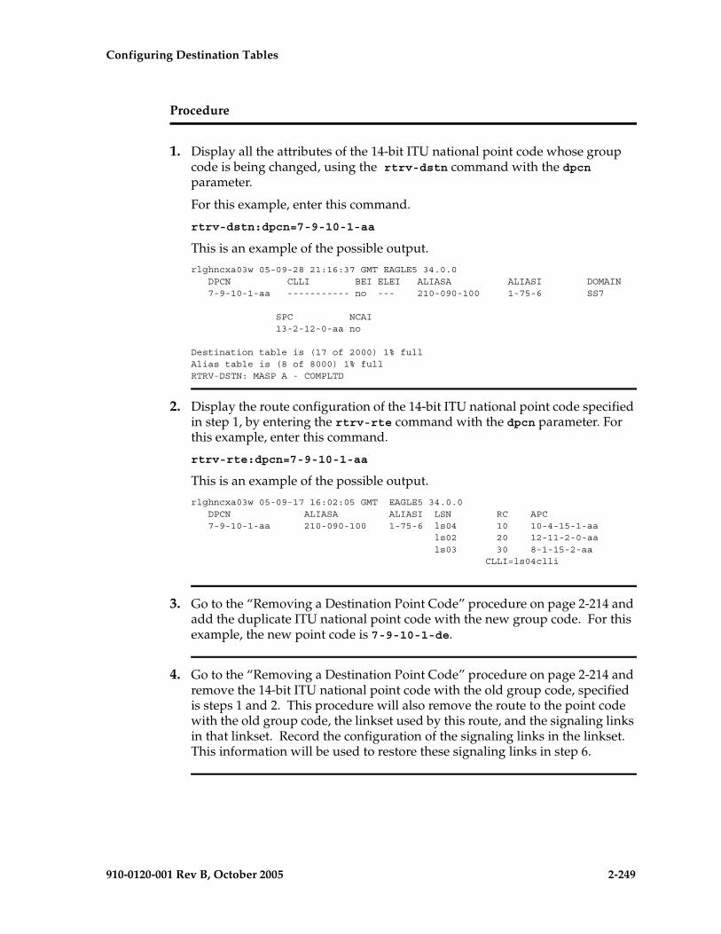
Configuring Destination Tables
910-0120-001 Rev B, October 2005 2-249
Procedure
1. Display all the attributes of the 14-bit ITU national point code whose group code is being changed, using the rtrv-dstn command with the dpcn parameter.
For this example, enter this command.
rtrv-dstn:dpcn=7-9-10-1-aa
This is an example of the possible output.
rlghncxa03w 05-09-28 21:16:37 GMT EAGLE5 34.0.0 DPCN CLLI BEI ELEI ALIASA ALIASI DOMAIN 7-9-10-1-aa ----------- no --- 210-090-100 1-75-6 SS7
SPC NCAI 13-2-12-0-aa no
Destination table is (17 of 2000) 1% fullAlias table is (8 of 8000) 1% fullRTRV-DSTN: MASP A - COMPLTD
2. Display the route configuration of the 14-bit ITU national point code specified in step 1, by entering the rtrv-rte command with the dpcn parameter. For this example, enter this command.
rtrv-rte:dpcn=7-9-10-1-aa
This is an example of the possible output.
rlghncxa03w 05-09-17 16:02:05 GMT EAGLE5 34.0.0 DPCN ALIASA ALIASI LSN RC APC 7-9-10-1-aa 210-090-100 1-75-6 ls04 10 10-4-15-1-aa ls02 20 12-11-2-0-aa ls03 30 8-1-15-2-aa CLLI=ls04clli
3. Go to the “Removing a Destination Point Code” procedure on page 2-214 and add the duplicate ITU national point code with the new group code. For this example, the new point code is 7-9-10-1-de.
4. Go to the “Removing a Destination Point Code” procedure on page 2-214 and remove the 14-bit ITU national point code with the old group code, specified is steps 1 and 2. This procedure will also remove the route to the point code with the old group code, the linkset used by this route, and the signaling links in that linkset. Record the configuration of the signaling links in the linkset. This information will be used to restore these signaling links in step 6.

2-250 910-0120-001 Rev B, October 2005
Configuring Destination Tables
NOTE: If the DPC specified in step 2 is not the adjacent point code of a linkset, shown in the APCN field of the rtrv-rte output, skip steps 5 and 6 and go to substep b of step 7.
5. Go to the “Adding an SS7 Linkset” procedure on page 3-17 and add a new linkset to the database containing the 14-bit ITU national point code with the new group code specified in step 3 as the APC of the linkset.
6. Go to the “Adding an SS7 Signaling Link” procedure on page 3-130 and add the signaling links that were removed by the “Removing a Destination Point Code” procedure in step 4 and specifying the linkset name of the linkset that was added in step 5.
7. If the DPC specified in step 2 is the adjacent point code of a linkset and a new linkset was created in step 5, then go to substep a. If the DPC specified in step 2 is not the adjacent point code of a linkset, then go to substep b. Do not perform substeps a and b.
a. Perform one of the “Adding a Route” procedures in Chapter 3 and add the route to the 14-bit ITU national point code with the new group code specifying the name of the linkset created in step 5 and the 14-bit ITU national point code with the new group code from step 3.
b. Perform one of the “Adding a Route” procedures in Chapter 3 and add the route to the 14-bit ITU national point code with the new group code specifying the 14-bit ITU national point code with the new group code from step 3.
8. Back up the new changes, using the chg-db:action=backup:dest=fixed command. These messages should appear; the active Maintenance and Administration Subsystem Processor (MASP) appears first.
BACKUP (FIXED) : MASP A - Backup starts on active MASP.BACKUP (FIXED) : MASP A - Backup on active MASP to fixed disk complete.BACKUP (FIXED) : MASP A - Backup starts on standby MASP.BACKUP (FIXED) : MASP A - Backup on standby MASP to fixed disk complete.

Configuring Destination Tables
910-0120-001 Rev B, October 2005 2-251
Flowchart 2-14. Changing the Group Code Assigned to a 14-Bit ITU National Point Code
Enter thertrv-dstn:dpcn= <xxxxx-yy>
command where <xxxxx-yy> isthe 14-bit ITU-N point code and
its associated group code
Is the DPC of theroute specified in the rtrv-rte
command output also theAPC of a linkset?
No
Yes
Enter thechg-db:action=backup:dest=fixed
command
Enter thertrv-rte:dpcn= <xxxxx-yy>
command where <xxxxx-yy> isthe 14-bit ITU-N point code and
its associated group code
Go to the "Duplicate ITU National PointCode Configuration" procedure and
enter the 14-bit ITU-N point code withthe new group code
Go to the "Removing a DestinationPoint Code" procedure and remove the
14-bit ITU-N DPC with the old groupcode
Go to the "Adding an SS7 Linkset"procedure and add a new linkset to thedatabase containing the 14-bit ITU-N
APC with the new group code
Go to the "Adding an SS7 SignalingLink" procedure and add the signaling
links that were removed in the"Removing a Destination Point Code"procedure to the database specifying
the new linkset name added in theprevious step for each signaling link
Perform one of the "Adding a Route"procedures in Chapter 3 and add the route
specifying the new linkset name and the14-bit ITU-N DPC with the new group code
Perform one of the "Adding a Route"procedures in Chapter 3 and add theroute specifying the 14-bit ITU-N DPC
with the new group code

2-252 910-0120-001 Rev B, October 2005
Configuring Destination Tables
910-0120-001 Rev B, October 2005 3-1
3
SS7 Configuration
Introduction...................................................................................................... 3–3
Enabling the Large System # Links Controlled Feature........................... 3–10
Adding an SS7 Linkset.................................................................................. 3–17
Removing a Linkset Containing SS7 Signaling Links .............................. 3–63
Changing an SS7 Linkset .............................................................................. 3–74
Configuring an ITU Linkset with a Secondary Adjacent Point Code (SAPC) ...........................................................................................3-113
Adding an SS7 Signaling Link ................................................................... 3–130
Removing an SS7 Signaling Link ..............................................................3–145
Adding a Route Containing an SS7 DPC ................................................. 3–153
Adding a Route Containing a Cluster Point Code ................................. 3–164
Adding a Route Containing an IPGWx Linkset...................................... 3–172
Adding a Route Containing an X.25 DPC................................................ 3–181
Removing a Route ....................................................................................... 3–189
Changing a Route ........................................................................................ 3–206
Changing Level 2 Timers............................................................................ 3–219
Changing Level 3 Timers............................................................................ 3–222
Changing a Signaling Link Test Message................................................. 3–228
Configuring Circular Route Detection .....................................................3–231
Configuring the TFA/TFR Pacing Rate.................................................... 3–235

3-2 910-0120-001 Rev B, October 2005
SS7 Configuration
Configuring the Frequency of RST Messages on Low Priority Routes...................................................................................................... 3-238
Adding Remote Loopback Points..............................................................3–241
Removing Remote Loopback Points .........................................................3–247
Changing Remote Loopback Points..........................................................3–250
Configuring the System for Random SLS Generation ...........................3–254
Configuring the Options for the TDM Global Timing Interface...........3–263
Configuring the Restricted Linkset Option..............................................3–269
Configuring the Options for Handling TFCs on ITU-I and ITU-N Networks ............................................................................................... 3-276
Changing the HC MIM Temperature Alarm Thresholds.......................3–279

SS7 Configuration
910-0120-001 Rev B, October 2005 3-3
Introduction
This chapter contains the procedures necessary to configure the EAGLE 5 SAS to support the SS7 network. These items are configured to support the SS7 network.
• Linksets, including linksets for these features:
– MTP restart
– 5-Bit to 8-Bit SLS conversion
– ITU SLS enhancement
– Configuring the option for determining how the EAGLE 5 SAS routes messages over restricted linksets and routes - the restricted linkset option.
– Configuring the options for determining how the EAGLE 5 SAS handles TFC messages from ITU-I and ITU-N networks.
• Signaling links
• Routes
• Level 2 timers
• Level 3 timers
• Signaling link test messages
• The rate that TFA and TFP messages are sent
• Circular route detection
• The frequency that signaling-route-set-test (RST) messages are sent for lower priority routes
• Remote loopback points for the link fault sectionalization feature
• Options for the TDM Global Timing Interface
• Configuring the HC MIM temperature alarm thresholds.
Figure 3-1 on page 3-4 shows the relationships of the database elements that are configured in these procedures.

3-4 910-0120-001 Rev B, October 2005
SS7 Configuration
Figure 3-1. SS7 Database Relationships
The procedures shown in this chapter use a variety of commands. If more information on these commands is needed, go to the Commands Manual to find the required information.
In addition to the items discussed in this section, other entities must be configured in the database to support the SS7 network. The entities that are required for the particular SS7 entity are listed with the particular procedure. They are also shown here to give an overview of what is required to configure the EAGLE 5 SAS to support the SS7 network. These entities (shown in Figure 3-1) must also be configured in the order that they are shown.
1. Make sure that the required shelf is in the database with the rtrv-shlf command. If it is not in the database, go to the “Adding a Shelf” procedure in the Database Administration Manual - System Management and add it with the ent-shlf command.

SS7 Configuration
910-0120-001 Rev B, October 2005 3-5
2. Make sure the cards that the SS7 signaling links will be assigned to are in the database with the rtrv-card command. These cards must be LIMs or DCMs. The LIMs must have either the limds0, limocu, or limv35 card type and either the ss7ansi, or ccs7itu application assigned to them. The DCMs must have the card type dcm and either the iplim, iplimi, ss7ipgw, or ipgwi application assigned to it. Table 3-1 shows the application type(s) valid for LIM and DCM signaling card types and the signaling link assignment. The ss7ansi, iplim, and ss7ipgw applications are used for signaling links assigned to linksets with ANSI adjacent point codes (APCs). The ccs7itu, iplimi, and ipgwi applications are used for signaling links assigned to linksets with ITU APCs (ITU international or ITU national point codes - 14-bit or 24-bit ITU-N point codes). The iplim, iplimi, ss7ipgw, and ipgwi applications are used for SS7-IP connectivity.
If these cards are not in the database, add them with the ent-card command, specifying a card type and an application. To add a LIM card, go to the “Adding an SS7 LIM” procedure in the Database Administration Manual - System Management. To add a DCM card for SS7-IP connectivity, go to the “Adding an IP Card” procedure in the Database Administration Manual - IP7 Secure Gateway.
3. The SS7 network configuration for the EAGLE 5 SAS requires linksets and routes. These entities use point codes and these point codes must be defined in the database. When nodes in different networks wish to communicate, each node must have either a true point code (TPC) or an alternate point code for each of the two network types involved. For example, if node1 in an ANSI network wishes to communicate with node2 in an ITU-N network, node1 must have an ANSI TPC and an ITU-N alternate point code; and node2 must have an ITU-N TPC and an ANSI alternate point code. For internetwork
Table 3-1. SS7 Signaling Link Card Types and Applications
Application Type
Card Type Signaling Link Assignment
limds0 limocu limv35 dcm
ccs7itu X X X to linksets with ITU adjacent point codes
ss7ansi X X X to linksets with ANSI adjacent point codes
iplim X to TCP/IP ANSI adjacent point codes
iplimi X to TCP/IP ITU adjacent point codes
ss7ipgw X to TCP/IP ANSI adjacent point codes
ipgwi X to TCP/IP ITU adjacent point codes
3-6 910-0120-001 Rev B, October 2005
SS7 Configuration
communication, the MTP3 routing label is converted. Conversions that fail, result in discarded MSUs with appropriate MRN outputs to the user terminals, for example, MRN 1091: RPT_MRN_UNKNOWN_DPC.
Verify that the necessary point codes are in the database with the rtrv-dstn command. If they are not in the database, go to the “Adding a Destination Point Code” procedure on page 2-191 and add them with the ent-dstn command. The point codes must be assigned to the SS7 domain.
4. The linksets that will contain the SS7 signaling links must be in the database. A linkset is a group of links that terminate into the same adjacent point code. All links in the linkset can transport compatible MSU formats. The network type of the adjacent point code assigned to the linkset determines the network type of the linkset. These linksets must be assigned an adjacent point code (APC) that is in the SS7 domain. Verify this with the rtrv-ls command. If the APC is in the SS7 domain, the entry SS7 is shown in the DOMAIN field of the output. Mated nodes are connected through C links. Since each destination is only reachable by linksets that match that destinations network type, mated nodes require a C-link linkset for each network the node is connected to. For nodes with three true point codes (TPCs), there needs to be a C linkset to transport ANSI formatted MSUs, a C linkset to transport ITU-N formatted MSUs, and a C linkset to transport ITU-I formatted MSUs. A TPC uniquely identifies the node in the network.
If the necessary linksets are not in the database, go to the “Adding an SS7 Linkset” procedure on page 3-17 and add them with the ent-ls command. Specify an APC that is in the database and in the SS7 domain added in step 3. The APC of the linkset must be a true point code and not an alias point code. The apc parameter must be of the same type as the DPC chosen in step 3.
5. The SS7 signaling links must be in the database. Verify this with the rtrv-slk command. The SS7 signaling links are assigned to linksets in the SS7 domain from step 4. SS7 signaling links are assigned to LIMs with the ss7ansi or ccs7itu application or to DCMs with the iplim, iplimi, ss7ipgw, or ipgwi application from step 2. If the LIM’s application is ss7ansi, then the linkset’s APC must be an ANSI APC. If the LIM’s application is ccs7itu, then the linkset’s APC can be either an ITU international APC or an ITU national APC (either a 14-bit or 24-bit ITU-N point codes). If the DCM’s application is iplim or ss7ipgw, then the linkset’s APC must be an ANSI APC. If the DCM’s application is iplimi or ipgwi, then the linkset’s APC can be either an ITU international APC or an ITU national APC.
If the necessary SS7 signaling links are not in the database, go to the “Adding an SS7 Signaling Link” procedure on page 3-130 and add them with the ent-slk command.

SS7 Configuration
910-0120-001 Rev B, October 2005 3-7
6. When SS7 signaling links for IP cards with card type iplim, iplimi, ss7ipgw, and ipgwi are added to the database, there are parameters that control the behavior of the signaling links that are not configured with the ent-slk command. The configuration of these values are described in the Database Administration Manual - IP7 Secure Gateway
7. The linksets must be assigned to a route. These linksets must contain APCs in the SS7 domain. The DPCs of these routes must be in the database and in the SS7 domain. Verify this with the rtrv-rte command. If the necessary routes are not in the database, go to one of these procedures and add the routes to the database with the ent-rte command, specifying a point code in the SS7 domain, from step 3, and a linkset with an SS7 APC, from step 4.
• “Adding a Route Containing an SS7 DPC” procedure on page 3-153
• “Adding a Route Containing a Cluster Point Code” procedure on page 3-164
• “Adding a Route Containing an IPGWx Linkset” procedure on page 3-172
• “Adding a Route Containing an X.25 DPC” procedure on page 3-181
By using the iplim, iplimi, ss7ipgw, and ipgwi applications, the entire EAGLE 5 SAS will be able to communicate via TCP/IP to the rest of the SS7 network elements. When properly configured, the EAGLE 5 SAS will be able to convert between any of the ANSI, ITU-N, and ITU-I networks, switch traffic between these networks, and perform network management for each of these networks.
Figure 3-2 on page 3-8 shows an example of a complex network with ANSI, ITU-I, and ITU-N nodes.

3-8 910-0120-001 Rev B, October 2005
SS7 Configuration
Figure 3-2. Complex Network with ANSI, ITU-I, and ITU-N Nodes
���
����
���
��
��
��
����
���
����
���
����
��
��
��
� � �
������
������
������
� � �
� �� �� �
� �� �� �
����
��
��
��
���
����
���
����
��
��
��
���
����
���
����
��
��
��
���
����
���
��� �
� �
� �
� �
����� �����
�����
�����
����
���
����
���
� �����
� �����
�������� ������������������
����� �����
��
�� �
�� �
��
����
����
����
��� �
��� �
��� �
� �� �� �
� �� �� �
� �� �� �

SS7 Configuration
910-0120-001 Rev B, October 2005 3-9
Figure 3-3 shows a typical SS7 network configuration and is used in this chapter for example configurations. Table 3-6, “Linkset Configuration Table,” on page 3-35, Table 3-11, “Low-Speed Signaling Link Configuration Table,” on page 3-134 show the database information that must be configured to establish this network.
Figure 3-3. Sample SS7 Network Configuration
001-001-0011-200-613842
002-002-002 003-003-003
004-004-004
003-020-100
004-030-200
002-250-010
3-150-4
002-007-008 009-002-003 10685 002-009-003 001-002-003
LS01
LS02
LS03
LS04LS05LSN5LS07LS06
LSI7

3-10 910-0120-001 Rev B, October 2005
SS7 Configuration
Enabling the Large System # Links Controlled Feature
This procedure is used to enable the Large System # Links controlled feature using the feature’s part number and a feature access key.
The feature access key for the Large System # Links controlled feature is based on the feature’s part number and the serial number of the EAGLE 5 SAS, making the feature access key site-specific.
This feature allows the EAGLE 5 SAS to contain up to 1500 signaling links. The part number for this feature is 893-0059-01.
The enable-ctrl-feat command enables the controlled feature by inputting the controlled feature’s access key and the controlled feature’s part number with these parameters:
:fak – The feature access key generated by Tekelec’s feature access key generator, and supplied to you when you purchase or temporarily try a controlled feature. The feature access key contains 13 alphanumeric characters and is not case sensitive.
:partnum – The Tekelec-issued part number associated with the controlled feature. The part number is a 9-digit number, not including dashes; the first three digits must be 893 (that is, 893xxxxxx, where x is a numeric value).
The enable-ctrl-feat command requires that the database contain a valid serial number for the EAGLE 5 SAS, and that this serial number is locked. This can be verified with the rtrv-serial-num command. The EAGLE 5 SAS is shipped with a serial number in the database, but the serial number is not locked. The serial number can be changed, if necessary, and locked once the EAGLE 5 SAS is on-site, by using the ent-serial-num command. The ent-serial-num command uses these parameters.
:serial – The serial number assigned to the EAGLE 5 SAS. The serial number is not case sensitive.
:lock – Specifies whether or not the serial number is locked. This parameter has only one value, yes, which locks the serial number. Once the serial number is locked, it cannot be changed.
NOTE: To enter and lock the EAGLE 5 SAS’s serial number, the ent-serial-num command must be entered twice, once to add the correct serial number to the database with the serial parameter, then again with the serial and the lock=yes parameters to lock the serial number. You should verify that the serial number in the database is correct before locking the serial number. The serial number can be found on a label affixed to the control shelf (shelf 1100).
This feature cannot be temporarily enabled (with the temporary feature access key).

SS7 Configuration
910-0120-001 Rev B, October 2005 3-11
Once this feature is enabled with the enable-ctrl-feat command, the feature is also activated. The chg-ctrl-feat command is not necessary to activate the feature.
This feature cannot be disabled with the chg-ctrl-feat command and the status=off parameter.
Procedure
1. Display the status of the Large System # Links controlled feature by entering the rtrv-ctrl-feat command. The following is an example of the possible output.
rlghncxa03w 05-09-28 21:15:37 GMT EAGLE5 34.0.0The following features have been permanently enabled:
Feature Name Partnum Status QuantityIPGWx Signaling TPS 893012814 on 20000ISUP Normalization 893000201 on ----Command Class Management 893005801 on ----LNP Short Message Service 893006601 on ----Intermed GTT Load Sharing 893006901 on ----XGTT Table Expansion 893006101 on 400000XMAP Table Expansion 893007710 off ----Routesets 893006401 on 6000HC-MIM SLK Capacity 893012707 on 64
The following features have been temporarily enabled:
Feature Name Partnum Status Quantity Trial Period LeftZero entries found.
The following features have expired temporary keys:
Feature Name PartnumZero entries found.
If the rtrv-ctrl-feat output shows that the controlled feature is permanently enabled for the desired quantity or for a quantity that is greater than the desired quantity, no further action is necessary. This procedure does not need to be performed.
NOTE: If the rtrv-ctrl-feat output in step 1 shows any controlled features, or if the Large System # Links controlled feature is enabled for a quantity that is less than the desired quantity, skip steps 2 through 5, and go to step 6.
2. Display the serial number in the database with the rtrv-serial-num command. This is an example of the possible output.
rlghncxa03w 05-09-28 21:15:37 GMT EAGLE5 34.0.0System serial number = nt00001231
System serial number is not locked.
rlghncxa03w 05-09-28 21:15:37 GMT EAGLE5 34.0.0Command Completed

3-12 910-0120-001 Rev B, October 2005
SS7 Configuration
NOTE: If the serial number is correct and locked, skip steps 3, 4, and 5, and go to step 6. If the serial number is correct but not locked, skip steps 3 and 4, and go to step 5. If the serial number is not correct, but is locked, this feature cannot be enabled and the remainder of this procedure cannot be performed. Contact the Customer Care Center to get an incorrect and locked serial number changed. Refer to “Customer Care Center” on page 1-8 for the contact information. The serial number can be found on a label affixed to the control shelf (shelf 1100).
3. Enter the correct serial number into the database using the ent-serial-num command with the serial parameter.
For this example, enter this command.ent-serial-num:serial=<EAGLE 5 SAS’s correct serial number>
When this command has successfully completed, the following message should appear.rlghncxa03w 05-09-28 21:15:37 GMT EAGLE5 34.0.0ENT-SERIAL-NUM: MASP A - COMPLTD
4. Verify that the serial number entered into step 3 was entered correctly using the rtrv-serial-num command. This is an example of the possible output.
rlghncxa03w 05-09-28 21:15:37 GMT EAGLE5 34.0.0System serial number = nt00001231
System serial number is not locked.
rlghncxa03w 05-09-28 21:15:37 GMT EAGLE5 34.0.0Command Completed
If the serial number was not entered correctly, repeat steps 3 and 4 and re-enter the correct serial number.
5. Lock the serial number in the database by entering the ent-serial-num command with the serial number shown in step 2, if the serial number shown in step 2 is correct, or with the serial number shown in step 4, if the serial number was changed in step 3, and with the lock=yes parameter.
For this example, enter this command.ent-serial-num:serial=<EAGLE 5 SAS’s serial number>:lock=yes
When this command has successfully completed, the following message should appear.rlghncxa03w 05-09-28 21:15:37 GMT EAGLE5 34.0.0ENT-SERIAL-NUM: MASP A - COMPLTD
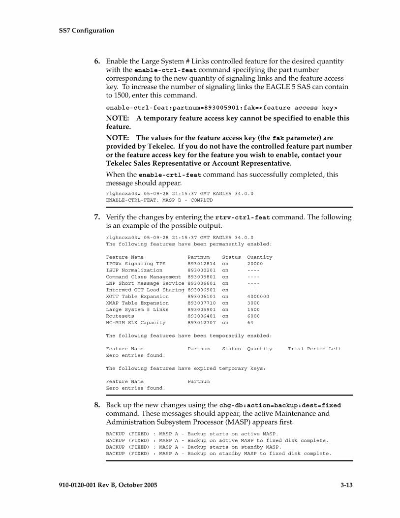
SS7 Configuration
910-0120-001 Rev B, October 2005 3-13
6. Enable the Large System # Links controlled feature for the desired quantity with the enable-ctrl-feat command specifying the part number corresponding to the new quantity of signaling links and the feature access key. To increase the number of signaling links the EAGLE 5 SAS can contain to 1500, enter this command.
enable-ctrl-feat:partnum=893005901:fak=<feature access key>
NOTE: A temporary feature access key cannot be specified to enable this feature.
NOTE: The values for the feature access key (the fak parameter) are provided by Tekelec. If you do not have the controlled feature part number or the feature access key for the feature you wish to enable, contact your Tekelec Sales Representative or Account Representative.
When the enable-crtl-feat command has successfully completed, this message should appear.rlghncxa03w 05-09-28 21:15:37 GMT EAGLE5 34.0.0ENABLE-CTRL-FEAT: MASP B - COMPLTD
7. Verify the changes by entering the rtrv-ctrl-feat command. The following is an example of the possible output.
rlghncxa03w 05-09-28 21:15:37 GMT EAGLE5 34.0.0The following features have been permanently enabled:
Feature Name Partnum Status QuantityIPGWx Signaling TPS 893012814 on 20000ISUP Normalization 893000201 on ----Command Class Management 893005801 on ----LNP Short Message Service 893006601 on ----Intermed GTT Load Sharing 893006901 on ----XGTT Table Expansion 893006101 on 4000000XMAP Table Expansion 893007710 on 3000Large System # Links 893005901 on 1500Routesets 893006401 on 6000HC-MIM SLK Capacity 893012707 on 64
The following features have been temporarily enabled:
Feature Name Partnum Status Quantity Trial Period LeftZero entries found.
The following features have expired temporary keys:
Feature Name PartnumZero entries found.
8. Back up the new changes using the chg-db:action=backup:dest=fixed command. These messages should appear, the active Maintenance and Administration Subsystem Processor (MASP) appears first.
BACKUP (FIXED) : MASP A - Backup starts on active MASP.BACKUP (FIXED) : MASP A - Backup on active MASP to fixed disk complete.BACKUP (FIXED) : MASP A - Backup starts on standby MASP.BACKUP (FIXED) : MASP A - Backup on standby MASP to fixed disk complete.

3-14 910-0120-001 Rev B, October 2005
SS7 Configuration
Flowchart 3-1. Enabling the Large System # Links Controlled Feature (Sheet 1 of 3)
Enter the rtrv-ctrl-featcommand
Yes
No
ToSheet 2
Is the quantity shown inthe rtrv-ctrl-feat output for the LargeSystem # Links controlled feature
the desired quantity?
Is the quantity shownin the rtrv-ctrl-feat output for theLarge System # Links controlledfeature greater than the desired
quantity?
The Large System # Linkscontrolled feature is
permanently enabled and thedesired quantity can be used.No further action is necessary.
Yes
No
No
Yes
Is the LargeSystem # Links controlled
feature permanentlyenabled?

SS7 Configuration
910-0120-001 Rev B, October 2005 3-15
Flowchart 3-1. Enabling the Large System # Links Controlled Feature (Sheet 2 of 3)

3-16 910-0120-001 Rev B, October 2005
SS7 Configuration
Flowchart 3-1. Enabling the Large System # Links Controlled Feature (Sheet 3 of 3)
FromSheet 2
Enter theenable-ctrl-feat:partnum=893005901:fak=<feature access key> command
Note: If you do not have the controlled feature partnumber or the feature access key for the controlledfeature you wish to enable, contact your Tekelecsales representative or account representative.
Enter the rtrv-ctrl-featcommand
Enter thechg-db:action=backup:dest=fixed
command

SS7 Configuration
910-0120-001 Rev B, October 2005 3-17
Adding an SS7 Linkset
This procedure is used to add SS7 linksets to the EAGLE 5 SAS using the ent-ls command without the gsmscrn, ipgwapc, iptps, lsusealm, and slkusealm, parameters of the ent-ls command.
The gsmscrn parameter is used for the GSM MAP Screening feature. To add an SS7 linkset for the GSM MAP Screening feature, perform the “Configuring a Linkset for the GSM MAP Screening Feature,” in Chapter 5, “GSM MAP Screening Configuration,” in the Database Administration Manual - Features.
The iptps, lsusealm, slkusealm, matelsn, and action parameters are used to configure IPGWx linksets. To configure IPGWx linksets, perform one of these procedures in Chapter 3, “IP7 Secure Gateway Configuration Procedures,” in the Database Administration Manual - IP7 Secure Gateway.
• “Configuring an IPGWx Linkset”
• “Configuring a Mate IPGWx Linkset”
To add X.25 linksets, go to the “Adding an X.25 Linkset” procedure in the Database Administration Manual – Features.
The ent-ls command uses these parameters.
:lsn – The name of the linkset. The linkset name can contain up to 10 characters, with the first character being a letter. However, the SEAS interface supports only eight characters. If this linkset is displayed on the SEAS interface and the linkset name contains more than eight characters, only the first eight characters in the linkset name are shown. If this linkset name contains more than eight characters, and is specified with the linkset commands on the SEAS interface, only the first eight characters can be specified.
:apc/apca/apci/apcn/apcn24 – Adjacent point code – the point code identifying the node that is next to the EAGLE 5 SAS. The adjacent point code can be one of the following types of point codes:
:apc/apca – ANSI point code
:apci – ITU-I point code, ITU-I spare point code
:apcn – 14-bit ITU-N point code, 14-bit ITU-N spare point code
:apcn24 – 24-bit ITU-N point code
NOTE: See “Point Code Formats” on page 2-4 for a definition of the point code types that are used on the EAGLE 5 SAS and for a definition of the different formats that can be used for ITU national point codes. Private point codes can be assigned only to IPGWx linksets. The procedures for configuring IPGWx linksets are in the Database Administration Manual - IP7 Secure Gateway.

3-18 910-0120-001 Rev B, October 2005
SS7 Configuration
:apcntype – Specifies whether or not the linkset containing either a 14-bit ITU-N adjacent point code or a 24-bit ITU-N adjacent point code is being used in China (apcntype=itunchina) or in countries other than China (apcntype=itun). Signaling links in linksets with the apcntype=itunchina parameter are handled according to the specifications in YD/N 068-1997, Technical Specification of National No.7 Signaling System - Message Transfer Part (MTP). Signaling links in linksets with the apcntype=itun parameter are handled according to the specifications in ITU-T Q.2210 (07/96), Switching and Signaling, Broadband ISDN- Signaling Network Protocols. The default value for the apcntype parameter is itun.
Linksets shown in section of the rtrv-ls output with the LSN (CHINA) column (and with either the APCN or APCN24 column) have the acpntype=itunchina parameter assigned to them.
Linksets shown in section of the rtrv-ls output with the LSN column (and with either the APCN or APCN24 column) have the acpntype=itun parameter assigned to them.
:lst – The linkset type of the specified linkset
:clli – The Common Language Location Identifier assigned to this point code. The value of the clli parameter is only displayed in the rtrv-ls command output when a specific linkset is being displayed with the rtrv-ls:lsn=<linkset name> command.
:sltset – The signaling link test message record to be associated with the linkset.
:l3tset – The level 3 timer set table. This parameter identifies which level three timer set is to be assigned to this linkset.
:scrn – The name of the screenset to be assigned to this linkset if gateway screening is to be used.
:gwsa – Gateway screening action determines whether gateway screening (GWS) is on or off for the specified link set.
:gwsm – Gateway screening messaging is used to turn on or off the display of messages generated for each screened message. When an MSU is rejected by gateway screening, a message is output to alert personnel of the event.
:gwsd – Gateway screening MSU discard is used to turn on or off the discarding of MSUs that bypass the gateway screening function due to load shedding. Also use this parameter with the redirect function; MSUs that cannot be screened are discarded if you specify gwsd=on.
:bei – The broadcast exception indicator. This parameter indicates whether TFP (transfer prohibited) messages are allowed to be broadcast on the linkset. The yes parameter means TFPs are not broadcast. The no parameter means TFPs are broadcast.
:nis – specifies whether the National Spare for Network Indicator feature is on or off for the specific linkset. This feature allows the linkset to use the national spare value (3) for the network indicator code field in the service

SS7 Configuration
910-0120-001 Rev B, October 2005 3-19
information octet (SIO) of the MSU for ANSI linksets and ITU national linksets (linksets containing either 14-bit ITU-N point codes or 24-bit ITU-N point codes). This parameter cannot be specified for ITU international linksets. The default value for the nis parameter is off.
For MSUs on incoming linksets, only those MSUs having the network indicator code values shown in Table 3-2 on page 3-19 are allowed into the EAGLE 5 SAS.
For MSUs on outgoing linksets, the network indicator code value in the MSU is changed to either the national network indicator code value (2) or the national spare network indicator code value (3). If the nis parameter is set to off, the network indicator code value is set to 2.
These actions are summarized in Table 3-2 on page 3-19.
The actions described for this parameter apply only if the ITU National and International Spare Point Code Support feature is not enabled.
If the ITU National and International Spare Point Code Support feature is enabled, the nis parameter value is ignored for ITU-I and 14-bit ITU-N linksets. All the network indicator values are permitted on ITU-I and ITU-N linksets, and the network indicator value for transmission is based on the International/National and Spare/Non-Spare status of the DPC of the message.
Having the ITU National and International Spare Point Code Support feature enabled has no effect on ANSI and 24-bit ITU-N linksets. The nis parameter value determines which incoming network indicator spare bit values to permit, and what network indicator spare bit value should be transmitted.
Table 3-2. Actions of the National Spare for Network Indicator Feature
Linkset Type Feature Disabled Feature Enabled
Incoming ANSI Linkset
MSUs containing the national network indicator code (2) are allowed into the EAGLE 5 SAS.
MSUs containing these network indicator code values are allowed into the EAGLE 5 SAS.• National Network Indicator Code
(2)• National Spare Network Indicator
Code (3)
Outgoing ANSI Linkset
The network indicator code value in the MSU is set to the national network indicator code (2).
The network indicator code value in the MSU is set to the national spare network indicator code (3).
Incoming ITU National Linkset
MSUs containing these network indicator code values are allowed into the EAGLE 5 SAS.• International Network
Indicator Code (0)• National Network
Indicator Code (2)
MSUs containing these network indicator code values are allowed into the EAGLE 5 SAS.• International Network Indicator
Code (0)• National Network Indictor Code (2)• National Spare Network Indicator
Code (3)

3-20 910-0120-001 Rev B, October 2005
SS7 Configuration
:itutfr – specifies whether or not ITU TFR (transfer restricted) procedures are being used on the linkset. This parameter applies only to linksets with ITU national adjacent point codes (linksets containing either 14-bit ITU-N point codes or 24-bit ITU-N point codes) and can be specified only for linksets with ITU national adjacent point codes. TFR procedures are used to redirect traffic away from a node that is having problems routing traffic to a destination. When a node determines that a destination is restricted, the node sends a TFR message informing the adjacent nodes about the destination’s status. When a destination is restricted, the node should not be used to route messages to the destination even though it still has limited capability to do so. The values for this parameter are either on (ITU TFR procedures are enabled) or off (ITU TFR procedures are disabled).
:mtprse – shows if the node adjacent to the EAGLE 5 SAS is equipped with the MTP restart capability. The mtprse=yes parameter can only be specified if the MTP restart feature is turned on for ANSI linksets (MTPRS = on in the rtrv-feat command output), or if the ITU MTP restart is on for ITU linksets (ITUMTPRS=on in the rtrv-feat command output). If the MTP restart feature is not turned on, or the APC of the linkset is in the X25 domain, the value of the mtprse parameter defaults to no. The value of the mtprse parameter value is not dependent on the value of the mtprsi parameter (the MTP restart indicator) in the chg-stpopts command. The value of the mtprse parameter is only displayed in the rtrv-ls command output when a specific linkset is being displayed with the rtrv-ls:lsn=<linkset name> command.
NOTE: For more information on the mtprse parameter and MTP restart, see “MTP Restart” on page 3-24.
:slsci – indicates whether the 5-bit to 8-bit SLS conversion feature is used to select signaling links for outgoing messages on the specified link set. If the slsci=yes parameter is specified, the EAGLE 5 SAS replaces any 5-bit SLS values contained in received messages with a random 8-bit value before they are used by the EAGLE 5 SAS to select the outgoing signaling link in that linkset. The 5-bit to 8-bit SLS conversion is also controlled by the slscnv parameter of the chg-stpopts command. The slscnv parameter of the chg-stpopts command has three values: on, off, and perls.
The slsci parameter can only be specified for linksets with ANSI SS7 adjacent point codes.
:asl8 – shows if the node adjacent to the EAGLE 5 SAS is sending MSUs with 8-bit SLSs. If the asl8=yes parameter is specified with the lst=a parameter (a
Outgoing ITU National Linkset
The network indicator code value in the MSU is set to the national network indicator code (2).
The network indicator code value in the MSU is set to the national spare network indicator code (3).
Table 3-2. Actions of the National Spare for Network Indicator Feature (Continued)
Linkset Type Feature Disabled Feature Enabled

SS7 Configuration
910-0120-001 Rev B, October 2005 3-21
linkset containing access signaling links), this indicates that the originator of the MSUs is generating 8-bit SLSs. For other linkset types, the asl8=yes parameter indicates that the adjacent node is converting 5-bit SLSs to 8-bit SLSs. The SLS in MSUs received by the EAGLE 5 SAS on a linkset that has the asl8=yes parameter assigned to it will not be converted. These MSUs are assumed to contain 8-bit SLSs. If the asl8=no parameter is specified for the linkset, the SLS will be converted to an 8-bit SLS. The asl8 parameter can only be specified for linksets with ANSI SS7 adjacent point codes. The value of the asl8 parameter is only displayed in the rtrv-ls command output when a specific linkset is being displayed with the rtrv-ls:lsn=<linkset name> command.
NOTE: For more information on the slsci and asl8 parameters and 5-bit to 8-bit conversion, see “5-Bit to 8-Bit SLS Conversion” on page 3-26.
:slsrsb – selects which bit (1 - 4) of the SLS field to use as the least significant bit for signaling link selection in the link set for all ITU messages.
:slsocbit – selects which bit (5 - 16) of the SLS field to use as the most significant bit for signaling link selection in the link set for all ITU messages.
NOTE: For more information on the slsrsb and slsocbit parameters and ITU SLS enhancement, see “ITU SLS Enhancement” on page 3-29.
:multgc – specifies whether multiple group codes (for 14-bit ITU-N point codes) are supported for the linkset. When this parameter value is yes, secondary adjacent point codes whose group codes are different from the adjacent point code of the linkset can be assigned to the linkset. If the parameter value is no, the group code of the secondary adjacent point code must be the same as the group code of the linkset’s adjacent point code. For more information on secondary adjacent point codes, go to the “Configuring an ITU Linkset with a Secondary Adjacent Point Code (SAPC)” procedure on page 3-113.
This parameter only applies to linksets whose adjacent point codes are either ITU international point codes or ITU national point codes. All the signaling links in this linkset must be assigned to cards running the IPLIMI application. For more information on assigning signaling links to cards running the IPLIMI application, go to the “Adding an IP Signaling Link” procedure in the Database Administration Manual - IP7 Secure Gateway.
The ITU duplicate point code feature must be on before this parameter can be specified. Verify this with the rtrv-feat command. If the ITU duplicate point code feature is turned on, the itupuppc field should be set to on. If the

3-22 910-0120-001 Rev B, October 2005
SS7 Configuration
ITU duplicate point code feature is not turned on, enter the chg-feat:itupuppc=on command.
NOTE: Once the ITU duplicate point code feature is turned on with the chg-feat command, it cannot be turned off.
The ITU duplicate point code feature must be purchased before you turn the feature on with the chg-feat command. If you are not sure if you have purchased the ITU duplicate point code feature, contact your Tekelec Sales Representative or Account Representative.
The linkset also contains the tfatcabmlq parameter, whose value is shown in the rtrv-ls:lsn=<linkset name> command. The tfatcabmlq parameter exists only in the chg-ls command and not the ent-ls command, because no links are assigned to the linkset when the linkset is first created with the ent-ls command. The default value for the tfatcabmlq parameter (tfatcabmlq=0) is entered for the linkset, and shown in the rtrv-ls output as 1, when a new linkset is added to the database.
The EAGLE 5 SAS can contain 1024 linksets, with a maximum of 255 of these linksets being gateway linksets. A gateway linkset is a linkset that contains routes to a different network.
The linkset to be added cannot be in the database. This can be verified in step 1 of this procedure.
The adjacent point code (APC) must be defined in the database, must be in the SS7 domain and cannot match the point code or capability point code of the EAGLE 5 SAS. This can be verified in steps 2 and 3 of this procedure. The domain of the point code is shown in the DOMAIN field in the output of the rtrv-dstn command (step 3). The point code of the EAGLE 5 SAS is shown in the PCA, PCN, PCN24, or PCI fields and the capability point code of the EAGLE 5 SAS are shown in the CPCA, CPCN, CPCN24, or CPCI fields in the output of the rtrv-sid command (step 2). The adjacent point code must be a full point code and cannot be a cluster point code or a network routing point code.
If the APC is not in the destination point code table, go to the “Adding a Destination Point Code” procedure on page 2-191 and add the APC to the destination point code table.
An X.25 APC cannot be referenced by an X.25 route that has the logical channel to network management function turned on (lc2nm=yes). Use the rtrv-x25-dstn command to verify which point codes are assigned to each X.25 address. Use the rtrv-x25-rte to verify which X.25 address is assigned to each X.25 route and to verify which X.25 route has the logical channel to network management function turned on, shown by the entry yes in the LC2NM field.
SS7 Configuration
910-0120-001 Rev B, October 2005 3-23
The ent-ls command has a parameter, gwsd, that can allow the discarding of messages that should have gone through the gateway screening process, but did not. The gwsd parameter is only intended to be used with the Database Transport Access (DTA) feature. If you are not using the DTA feature, the gwsd parameter should not be specified or should be set to no (gwsd=no).
The gwsa, gwsm, and gwsd parameters can only be specified if the scrn parameter is specified. If the scrn parameter is specified, the gateway screening screen set name specified by this parameter must also be defined as a gateway screening screen set entity. This can be verified with the rtrv-scrset command.
CAUTION: When Gateway Screening is in the screen test mode, as defined by the linkset parameters gwsa=off and gwsm=on, the gateway screening action in the gateway screening stop action set specified by the actname parameter of the gateway screening screen set at the end of the gateway screening process will be performed.
If the domain of the linkset’s APC is in the X.25 domain, the bei=yes parameter must be specified, or the bei parameter must be omitted.
To help manage congestion on signaling links, the EAGLE 5 SAS starts the level 3 T31 timer whenever a signaling link goes into congestion level 1 or congestion level 2. The congestion level that is associated with the level 3 T31 timer is set using the chg-stpopts command with the mtpt31ctl parameter and is displayed with the MTPT31CTL field in the rtrv-stpopts command output. When the level 3 timer T31 and the chg-stpopts command are first introduced to the EAGLE 5 SAS, the system default value for the mtpt31ctl parameter of the chg-stpopts command is 1, for congestion level 1, and the system default value for the level 3 T31 timer is 60 seconds. To change the value of the level 3 T31 timer, go to the “Changing Level 3 Timers” procedure on page 3-222. To change value of the mtpt31ctl parameter, enter the either chg-stpopts:mtpt31ctl=1 or the chg-stpopts:mtpt31ctl=2 command, depending on the current value of the mtpt31ctl parameter.
To help prevent the signaling link in the linkset from oscillating in out of service, the EAGLE 5 SAS starts the level 3 T32 timer. When the EAGLE 5 SAS begins restoring an out of service signaling link, the EAGLE 5 SAS starts the level 3 T32 timer. If the signaling link fails to get back into service before the level 3 T32 expires, the EAGLE 5 SAS does not attempt to continue to bring the signaling link into service until the level 3 T32 timer expires. Once the level 3 T32 timer expires, the EAGLE 5 SAS attempts to restore the signaling link into service. When the level 3 timer T32 is first introduced to the EAGLE 5 SAS, the default value for the level 3 T32 timer is 60 seconds. To change the value of the level 3 T32 timer, go to the “Changing Level 3 Timers” procedure on page 3-222.

3-24 910-0120-001 Rev B, October 2005
SS7 Configuration
The word SEAS cannot be used as a value for the scrn parameter of the ent-ls command. The word SEAS is used in the rtrv-ls command output, in the SCRN field, to show gateway linksets created on the SEAS interface. A gateway linkset combines the functions of a gateway screening screen set and an SS7 linkset specifying the gwsa=on and scrn parameters. Like a EAGLE 5 SAS gateway screening screen set, a gateway linkset defines the screening references that are to be used to screen the messages on the linkset. It also defines the linkset whose messages are to be screened. A gateway linkset can only be configured from a SEAS terminal and not from a EAGLE 5 SAS terminal.
If the clli parameter is specified with the ent-ls command, the value of the clli parameter must match the CLLI value of the adjacent point code of the linkset. The CLLI value of the adjacent point code is shown in the CLLI field of the rtrv-dstn command.
If the randsls parameter of the chg-stpopts command is set to either all or class0, a maximum of 16 links continues to be supported in a single linkset to a destination. However, it is now possible to have up to 32 links in a combined linkset to a destination, with a maximum of 16 links per linkset. The 32 links is a change from the current EAGLE 5 SAS maximum of only 16 links per combined linkset, which is due to ITU protocol restrictions. If more than 16 links are used in a combined linkset, the operator needs to be aware that a maximum of 16 links can be used by non-Random SLS traffic over the linkset. The non-Random SLS traffic continues to operate under the rules of the ITU protocol. For more information on the Random SLS Generation feature, go to the “Configuring the System for Random SLS Generation” procedure on page 3-254.
MTP Restart
If the MTP restart feature is turned on, the alignment of all ANSI signaling links is delayed until all the LIMs containing ANSI signaling links are in service. This allows the EAGLE 5 SAS to be restored to network service in an orderly fashion and allows all the LIMs containing ANSI signaling links to participate in the MTP restart process. The amount of time that the alignment of the signaling links is delayed is dependent on the number of LIMs and DCMs in the EAGLE 5 SAS and is shown in Table 3-3. Table 3-3 shows and example of MTP signaling link alignment delay for LIMs.
NOTE: The MTP restart feature cannot be used on linksets containing IP signaling links with the ipliml2=m3ua parameter. The MTP restart feature can be used on linksets containing non-IP signaling links or IP signaling links with either the ipliml2=saaltali or ipliml2=m2pa parameter.

SS7 Configuration
910-0120-001 Rev B, October 2005 3-25
If the ANSI MTP restart feature is on (MTPRS = on in the rtrv-feat command output), the mtprsi parameter is set to yes, and at least one ANSI linkset has the mtprse parameter set to yes, the EAGLE 5 SAS starts these level 3 timers; T22, T23, T24, T25, T26, T28, T29, and T30 to control the behavior of the MTP restart feature. These timers control when the TRA and TRW network management messages are sent to the nodes adjacent to the EAGLE 5 SAS when the EAGLE 5 SAS is going through the MTP restart process. When these timers are first introduced to the EAGLE 5 SAS, the system default values for these timers are:
• T22 - 10 seconds
• T23 - 10 seconds
• T24 - 10 seconds
• T25 - 30 seconds
• T26 - 12 seconds
• T28 - 3 seconds
• T29 - 60 seconds
• T30 - 30 seconds.
To change the values of these timers, go to the “Changing Level 3 Timers” procedure on page 3-222.
If the ITU MTP restart feature is on (ITUMTPRS = on in the rtrv-feat command output), the mtprsi parameter is set to yes, and at least one ITU linkset has the mtprse parameter set to yes, the EAGLE 5 SAS starts these level 3 timers; IT18, IT19, IT20, and IT21 to control the behavior of the ITU MTP restart feature. These timers control when the TRA and TRW network management messages are sent to the nodes adjacent to the EAGLE 5 SAS when the EAGLE 5 SAS is going through the MTP restart process. When these timers are first introduced to the EAGLE 5 SAS, the default values for these timers are:
• IT18 - 50 seconds
• IT19 - 67 seconds
Table 3-3. MTP Restart Signaling Link Alignment Delay
Number of LIMs Containing
Signaling Links
Signaling Link Alignment Delay
1 to 64 62 seconds
64 to 127 97 seconds
128 to 191 132 seconds
192 or more 167 seconds
3-26 910-0120-001 Rev B, October 2005
SS7 Configuration
• IT20 - 59 seconds
• IT21 - 63 seconds.
To change the values of these timers, go to the “Changing Level 3 Timers” procedure on page 3-222.
If both the ANSI and ITU MTP restart features are on, the mtprsi parameter is set to yes, and at least one ANSI and ITU linkset has the mtprse parameter set to yes, the EAGLE 5 SAS starts the level 3 timers for both the ANSI and ITU MTP restart features to control the behavior of both the ANSI and ITU MTP restart features.
5-Bit to 8-Bit SLS Conversion
5-Bit to 8-Bit SLS conversion is performed based on the values assigned to the slsci and asl8 parameters for the linkset and the slscnv parameter of the chg-stpopts command.
NOTE: The slsci and asl8 parameters can be specified only for linksets containing ANSI adjacent point codes.
The slsci parameter indicates whether the 5-bit to 8-bit SLS conversion feature is used to select signaling links for outgoing messages on the specified link set. If the slsci=yes parameter is specified, the EAGLE 5 SAS replaces any 5-bit SLS values contained in received messages with a random 8-bit value before they are used by the EAGLE 5 SAS to select the outgoing signaling link in that linkset. The 5-bit to 8-bit SLS conversion is also controlled by the slscnv parameter of the chg-stpopts command. The slscnv parameter of the chg-stpopts command has three values: on, off, and perls.
The asl8 parameter shows if the node adjacent to the EAGLE 5 SAS is sending MSUs with 8-bit SLSs. If the asl8=yes parameter is specified with the lst=a parameter (a linkset containing access signaling links), this indicates that the originator of the MSUs is generating 8-bit SLSs. For other linkset types, the asl8=yes parameter indicates that the adjacent node is converting 5-bit SLSs to 8-bit SLSs. The SLS in MSUs received by the EAGLE 5 SAS on a linkset that has the asl8=yes parameter assigned to it will not be converted. These MSUs are assumed to contain 8-bit SLSs. If the asl8=no parameter is specified for the linkset, the SLS will be converted to an 8-bit SLS. The value of the asl8 parameter is only displayed in the rtrv-ls command output when a specific linkset is being displayed with the rtrv-ls:lsn=<linkset name> command.
The interaction between the slsci and asl8 parameters of the ent-ls command and the slscnv parameter of the chg-stpopts command is shown in Table 3-4.

SS7 Configuration
910-0120-001 Rev B, October 2005 3-27
The slscnv parameter of the chg-stpopts command has three values: on, off, and perls.
• slscnv=on – 5-bit to 8-bit conversion is performed on all linksets in the EAGLE 5 SAS, regardless of what the value of the slsci parameter of the ent-ls or chg-ls command is for the specific linkset. If the asl8=yes parameter of either the ent-ls or chg-ls commands is assigned to the linkset, no SLS conversion is performed.
Table 3-4. Signaling Link Selector (SLS) Conversion (ANSI Linksets Only)
CHG-STPOPTS SLSCNV
Parameter Value
Outgoing Linkset SLSCI
Parameter Value
Incoming Linkset ASL8
Parameter ValueResult
ON Not Applicable YES
The adjacent node is sending 8-bit SLSs. No SLS conversion is performed on MSUs received on this linkset.
ON Not Applicable NO
The adjacent node is not sending 8-bit SLSs. 5-bit to 8-bit SLS conversion on MSUs received on this linkset.
OFF Not Applicable YESThe adjacent node is sending 8-bit SLSs. No SLS conversion is performed on any linksets.
OFF Not Applicable NO
The adjacent node is not sending 8-bit SLSs. 5-bit to 8-bit SLS conversion is not performed on all linksets.
PERLS* YES YESThe adjacent node is sending 8-bit SLSs. No SLS conversion is performed.
PERLS* YES NOThe adjacent node is not sending 8-bit SLSs. 5-bit to 8-bit SLS conversion is performed.
PERLS* NO YESThe adjacent node is sending 8-bit SLSs. No SLS conversion is performed.
PERLS* NO NOThe adjacent node is not sending 8-bit SLSs. 5-bit to 8-bit SLS conversion is not performed.
* When the slscnv=perls parameter is specified with the chg-stpopts command, 5-bit to 8-bit SLS conversion is only performed on the MSUs arriving at the EAGLE 5 SAS on linksets that have the asl8=no parameter of the ent-ls command assigned to them, and leaving the EAGLE 5 SAS on linksets that have the slsci=yes parameter of the ent-ls command assigned to them.
3-28 910-0120-001 Rev B, October 2005
SS7 Configuration
• slscnv=off – 5-bit to 8-bit conversion is not performed on the linksets in the EAGLE 5 SAS, regardless of what the value of the slsci parameter of the ent-ls or chg-ls command is for the specific linkset.
• slscnv=perls – 5-bit to 8-bit SLS conversion is only performed on the MSUs arriving at the EAGLE 5 SAS on linksets that have the asl8=no parameter assigned to them, and leaving the EAGLE 5 SAS on linksets that have the slsci=yes parameter assigned to them. The asl8 and slsci parameters are configured with either the ent-ls or chg-ls commands.
When a 5-bit ANSI SLS is converted to an 8-bit ANSI SLS, the three most significant bits of the SLS are set using a function of originating point code and incoming signaling link. This ensures that MSUs with the same originating point code, SLS, and incoming signaling link will always have the same SLS after the conversion, guaranteeing that the MSUs arrive at the destination in the same sequence that they were sent.
5-bit to 8-bit SLS conversion is performed under these conditions.
• The incoming linkset is an ANSI linkset, a linkset containing an ANSI adjacent point code.
• The asl8=no parameter of the ent-ls or chg-ls command is assigned to the incoming linkset.
• The outgoing linkset is an ANSI linkset.
• The slscnv=on parameter of the chg-stpopts command is specified
• The slscnv=perls parameter of the chg-stpopts command is specified and slsci=yes parameter of the ent-ls or chg-ls command assigned to the outgoing linkset.
• The three most significant bits of the SLS in the MSU are zero.
All ANSI MSUs originating from the EAGLE 5 SAS have an 8-bit SLS.
The EAGLE 5 SAS also converts ANSI SLSs to ITU SLSs, and ITU SLSs to ANSI SLSs.
When an ITU SLS is converted to an ANSI SLS, the ITU SLS is always converted to an ANSI 5-bit SLS. If the MSU containing the converted SLS is rerouted because of a link outage, the SLS may be converted from a 5-bit SLS to an 8-bit SLS.
When an ANSI SLS is converted to an ITU SLS, the ANSI SLS is always converted to an ITU 4-bit SLS.
The EAGLE 5 SAS does not convert a 4-bit ITU SLS to an 8-bit ANSI SLS.
The 5-bit to 8-bit SLS conversion takes place during the routing process, after the linkset is selected, but before the signaling link is selected. The ITU to ANSI SLS conversion takes place during the ANSI to ITU MSU conversion and after the outgoing signaling link is chosen.
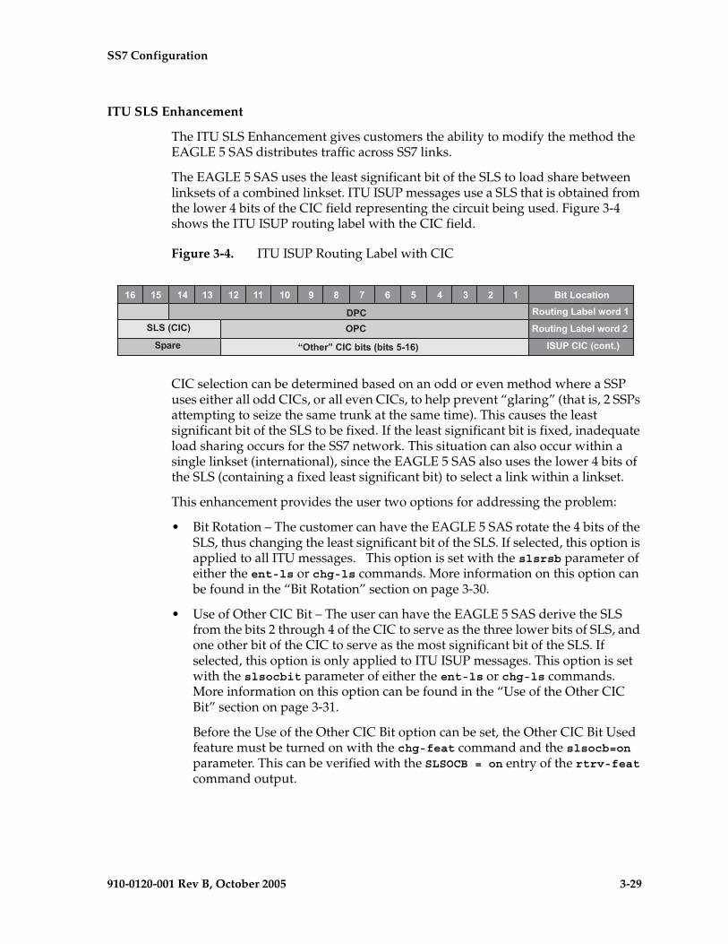
SS7 Configuration
910-0120-001 Rev B, October 2005 3-29
ITU SLS Enhancement
The ITU SLS Enhancement gives customers the ability to modify the method the EAGLE 5 SAS distributes traffic across SS7 links.
The EAGLE 5 SAS uses the least significant bit of the SLS to load share between linksets of a combined linkset. ITU ISUP messages use a SLS that is obtained from the lower 4 bits of the CIC field representing the circuit being used. Figure 3-4 shows the ITU ISUP routing label with the CIC field.
Figure 3-4. ITU ISUP Routing Label with CIC
CIC selection can be determined based on an odd or even method where a SSP uses either all odd CICs, or all even CICs, to help prevent “glaring” (that is, 2 SSPs attempting to seize the same trunk at the same time). This causes the least significant bit of the SLS to be fixed. If the least significant bit is fixed, inadequate load sharing occurs for the SS7 network. This situation can also occur within a single linkset (international), since the EAGLE 5 SAS also uses the lower 4 bits of the SLS (containing a fixed least significant bit) to select a link within a linkset.
This enhancement provides the user two options for addressing the problem:
• Bit Rotation – The customer can have the EAGLE 5 SAS rotate the 4 bits of the SLS, thus changing the least significant bit of the SLS. If selected, this option is applied to all ITU messages. This option is set with the slsrsb parameter of either the ent-ls or chg-ls commands. More information on this option can be found in the “Bit Rotation” section on page 3-30.
• Use of Other CIC Bit – The user can have the EAGLE 5 SAS derive the SLS from the bits 2 through 4 of the CIC to serve as the three lower bits of SLS, and one other bit of the CIC to serve as the most significant bit of the SLS. If selected, this option is only applied to ITU ISUP messages. This option is set with the slsocbit parameter of either the ent-ls or chg-ls commands. More information on this option can be found in the “Use of the Other CIC Bit” section on page 3-31.
Before the Use of the Other CIC Bit option can be set, the Other CIC Bit Used feature must be turned on with the chg-feat command and the slsocb=on parameter. This can be verified with the SLSOCB = on entry of the rtrv-feat command output.
�% �& �' �( �� �� �) * + � % & ' ( � � ����� �,��
��� � ��� !��,�-�� ����
����.�/�0 1�� � ��� !��,�-�� ����
�2,� 31�4�5��/�������.�����&��%0 /�#���/��.� �60

3-30 910-0120-001 Rev B, October 2005
SS7 Configuration
The slsrsb and slsocbit parameters can only be specified for linksets that contain either an ITU international or ITU national adjacent point code (either a 14-bit or 24-bit ITU-N adjacent point code).
The value of the slsrsb and slsocbit parameters are only displayed in the rtrv-ls command output when a specific linkset is being displayed with the rtrv-ls:lsn=<linkset name> command.
NOTE: If the randsls parameter of the chg-stpopts command, a system-wide option, is set to either all or class0, the EAGLE 5 SAS uses the Random SLS Generation feature to perform load sharing between ITU linksets. The slsrsb parameter value is ignored. However, the ent-ls and chg-ls commands allow the slsrsb parameter value to be specified. For more information on the Random SLS Generation feature, go to the “Configuring the System for Random SLS Generation” procedure on page 3-254.
Only the link selection algorithm is modified by this feature, not the actual SLS field of the message (that is, the SLS value received by the EAGLE 5 SAS is the SLS value sent by the EAGLE 5 SAS).
Bit Rotation
To alleviate the situation of the EAGLE 5 SAS selecting the same linkset of a combined linkset, the customer can apply the bit rotation option. Bit rotation can be used, on a per linkset basis, to ensure the EAGLE 5 SAS does not use the static least significant bit (always 0 or always 1) in the received SLS for linkset selection.
When defining a link set using the ent-ls or chg-ls commands, the customer will be able to select which bit (1-4) of the SLS field to use as the least significant bit for link set selection. This rotation only affects the 4 bits of the SLS during linkset selection, as follows:
• If bit 4 is selected, bit locations 4 3 2 1 will be rotated to 3 2 1 4.
For example: SLS = 0110 becomes Rotated SLS = 1100SLS = 1011 becomes Rotated SLS = 0111
• If bit 3 is selected, bit locations 4 3 2 1 will be rotated to 2 1 4 3.
For example: SLS = 0110 becomes Rotated SLS = 1001SLS = 1011 becomes Rotated SLS = 1110
• If bit 2 selected, bit locations 4 3 2 1 will be rotated to 1 4 3 2.
For example: SLS = 0110 becomes Rotated SLS = 0011SLS = 1011 becomes Rotated SLS = 1101
• If bit 1 is selected, no rotation is performed, since bit 1 is the existing least significant bit. Bit 1 is the default value.
Figure 3-5 shows an example of bit rotation.
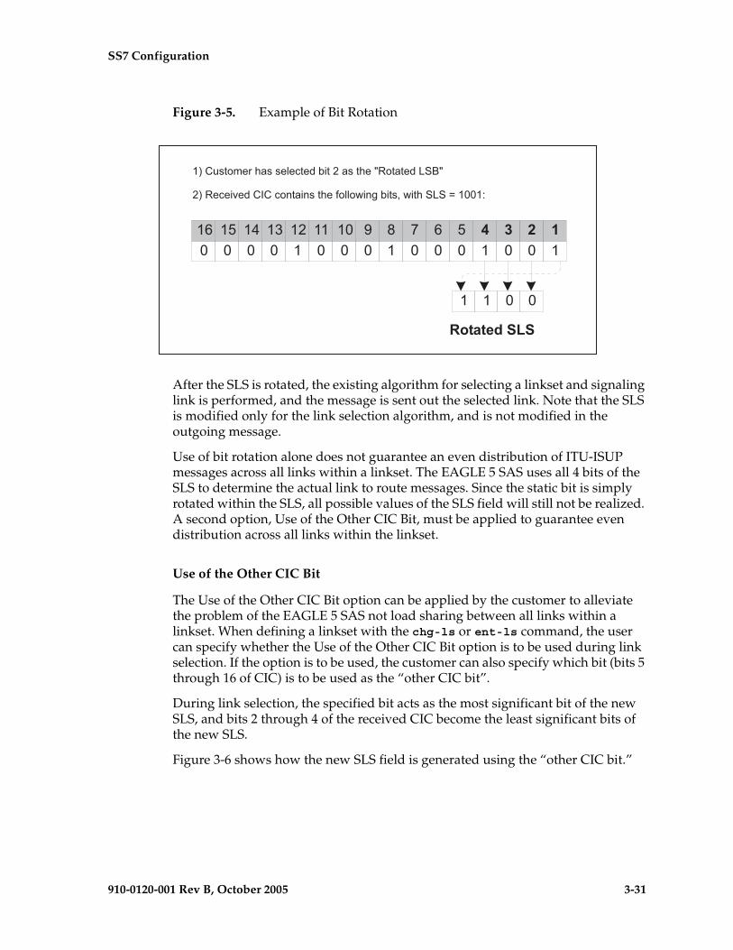
SS7 Configuration
910-0120-001 Rev B, October 2005 3-31
Figure 3-5. Example of Bit Rotation
After the SLS is rotated, the existing algorithm for selecting a linkset and signaling link is performed, and the message is sent out the selected link. Note that the SLS is modified only for the link selection algorithm, and is not modified in the outgoing message.
Use of bit rotation alone does not guarantee an even distribution of ITU-ISUP messages across all links within a linkset. The EAGLE 5 SAS uses all 4 bits of the SLS to determine the actual link to route messages. Since the static bit is simply rotated within the SLS, all possible values of the SLS field will still not be realized. A second option, Use of the Other CIC Bit, must be applied to guarantee even distribution across all links within the linkset.
Use of the Other CIC Bit
The Use of the Other CIC Bit option can be applied by the customer to alleviate the problem of the EAGLE 5 SAS not load sharing between all links within a linkset. When defining a linkset with the chg-ls or ent-ls command, the user can specify whether the Use of the Other CIC Bit option is to be used during link selection. If the option is to be used, the customer can also specify which bit (bits 5 through 16 of CIC) is to be used as the “other CIC bit”.
During link selection, the specified bit acts as the most significant bit of the new SLS, and bits 2 through 4 of the received CIC become the least significant bits of the new SLS.
Figure 3-6 shows how the new SLS field is generated using the “other CIC bit.”
����� �!"�#����$% �&� ������ #�'(� � ���)'
���(%�*�����%�� ����� #�+�$$�,��-�&� �.�,� #�����/� �� 0
� � �� � ('����� � � �� � �� � ��� ��� �
� �
� �,������
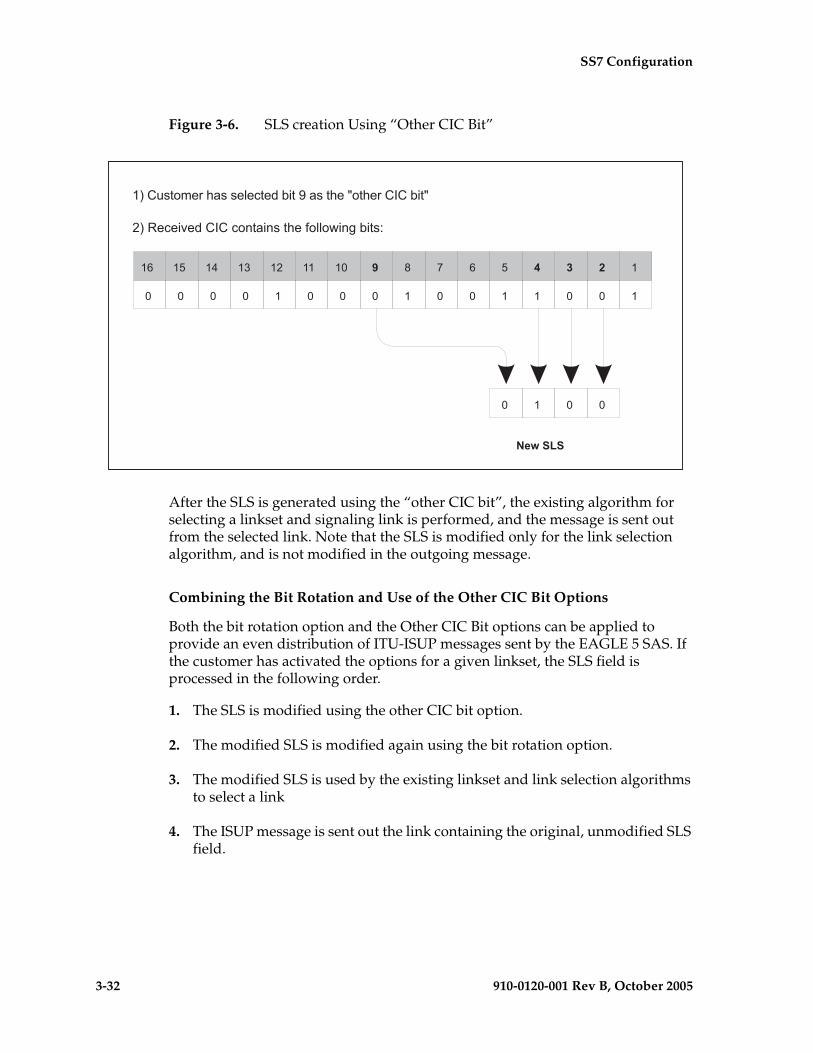
3-32 910-0120-001 Rev B, October 2005
SS7 Configuration
Figure 3-6. SLS creation Using “Other CIC Bit”
After the SLS is generated using the “other CIC bit”, the existing algorithm for selecting a linkset and signaling link is performed, and the message is sent out from the selected link. Note that the SLS is modified only for the link selection algorithm, and is not modified in the outgoing message.
Combining the Bit Rotation and Use of the Other CIC Bit Options
Both the bit rotation option and the Other CIC Bit options can be applied to provide an even distribution of ITU-ISUP messages sent by the EAGLE 5 SAS. If the customer has activated the options for a given linkset, the SLS field is processed in the following order.
1. The SLS is modified using the other CIC bit option.
2. The modified SLS is modified again using the bit rotation option.
3. The modified SLS is used by the existing linkset and link selection algorithms to select a link
4. The ISUP message is sent out the link containing the original, unmodified SLS field.
����� �!"�#����$% �&� ������ #�'� #"�����&� '
���(%�*�����%�� ����� #�+�$$�,��-�&� �0
� � �
�����
� � � � ('����* � � �
� � �� � �� ��� �
SS7 Configuration
910-0120-001 Rev B, October 2005 3-33
ITU TFR Procedures
Receiving TFR Messages
If ITU TFR procedures have been enabled for the linkset and a TFR message is received on that linkset, the EAGLE 5 SAS marks the route to the destination as restricted and performs controlled rerouting of the messages that are destined for the destination specified in the TFR message.
If ITU TFR procedures have not been enabled for the linkset and a TFR message is received on that linkset, the TFR message is converted to a TFA (transfer allowed) message and traffic is routed to the destination specified in the TFR message. When this condition is present and a TFR is received on this linkset, UIM 1233 is displayed showing that a TFR was received on a linkset that does not support the TFR procedure.
When a TFR message is received for a route that is already prohibited, and no alternative route exists, the traffic to the concerned node is restarted towards the signaling point from which the TFR message was received.
Invalid TFR messages
The TFR message is ignored under any of these conditions:
• The TFR message is not from an adjacent point code.
• The point code specified in the TFR message is being sent from that same point code.
• The TFR message is from an unknown destination.
• The TFR message is from an adjacent point code, but the adjacent point code is not the route for concerned point code.
• If the route to the concerned point code is already restricted.
• The route to concerned point code not found or is unavailable.
Sending TFR Messages
The EAGLE 5 SAS must send a TFR message containing the affected point code (restricted destination) to all accessible adjacent nodes, whose linkset has the TFR procedure enabled, when the following conditions are in effect:
• When long term failure occurs on the ITU-N linkset (primary) used to route messages to the affected point code. Long term failure occurs when all links of a linkset remain unavailable for more than the amount of time specified by level 3 timer T11.
• While waiting for “long term failure” to be determined, if congestion (or “danger of congestion”) is detected on an alternate linkset used to route
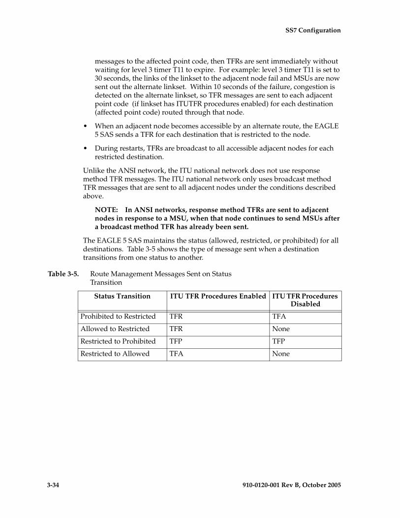
3-34 910-0120-001 Rev B, October 2005
SS7 Configuration
messages to the affected point code, then TFRs are sent immediately without waiting for level 3 timer T11 to expire. For example: level 3 timer T11 is set to 30 seconds, the links of the linkset to the adjacent node fail and MSUs are now sent out the alternate linkset. Within 10 seconds of the failure, congestion is detected on the alternate linkset, so TFR messages are sent to each adjacent point code (if linkset has ITUTFR procedures enabled) for each destination (affected point code) routed through that node.
• When an adjacent node becomes accessible by an alternate route, the EAGLE 5 SAS sends a TFR for each destination that is restricted to the node.
• During restarts, TFRs are broadcast to all accessible adjacent nodes for each restricted destination.
Unlike the ANSI network, the ITU national network does not use response method TFR messages. The ITU national network only uses broadcast method TFR messages that are sent to all adjacent nodes under the conditions described above.
NOTE: In ANSI networks, response method TFRs are sent to adjacent nodes in response to a MSU, when that node continues to send MSUs after a broadcast method TFR has already been sent.
The EAGLE 5 SAS maintains the status (allowed, restricted, or prohibited) for all destinations. Table 3-5 shows the type of message sent when a destination transitions from one status to another.
Table 3-5. Route Management Messages Sent on Status Transition
Status Transition ITU TFR Procedures Enabled ITU TFR Procedures Disabled
Prohibited to Restricted TFR TFA
Allowed to Restricted TFR None
Restricted to Prohibited TFP TFP
Restricted to Allowed TFA None

SS7 Configuration
910-0120-001 Rev B, October 2005 3-35
Sample Linkset Configuration
The examples used in this procedure are based on the example network shown in Figure 3-3 on page 3-9 and Table 3-6.
Canceling the RTRV-LS and RTRV-DSTN Commands
Because the rtrv-ls and rtrv-dstn commands used in this procedure can output information for a long period of time, the rtrv-ls and rtrv-dstn commands can be canceled and the output to the terminal stopped. There are three ways that the rtrv-ls and rtrv-dstn commands can be canceled.
• Press the F9 function key on the keyboard at the terminal where the rtrv-ls or rtrv-dstn commands were entered.
• Enter the canc-cmd without the trm parameter at the terminal where the rtrv-ls or rtrv-dstn commands were entered.
• Enter the canc-cmd:trm=<xx>, where <xx> is the terminal where the rtrv-ls or rtrv-dstn commands were entered, from another terminal other that the
Table 3-6. Linkset Configuration Table
LinksetNames
Linkset APC
LST CLLI SLTSET BEI IPGWAPC APCNTYPE
ls05 002-002-003 a N/A 1 no no N/A
ls06 002-007-008 a N/A 4 yes no N/A
ls07 009-002-003 a N/A 1 no no N/A
atmansi0 179-100-087 a N/A 16 yes no N/A
atmansi1 200-050-176 a rlghnccc001 9 no no N/A
lsi7 3-150-4 a N/A 2 N/A N/A N/A
lsn5 10685 a N/A 2 N/A N/A ITUN
lsn6 12543 a N/A 3 N/A N/A ITUNCHINA
LinksetNames
SCRN GWSA GWSD GWSM NIS ITUTFR
ls05 scr2 on on off off N/A
ls06 scr4 on off off on N/A
ls07 scr2 on on off off N/A
atmansi0 scr2 on off off off N/A
atmansi1 scr1 on off off off N/A
lsi7 scr1 on off N/A N/A N/A
lsn5 scr3 on off N/A N/A yes
lsn6 scr3 on off N/A N/A yes

3-36 910-0120-001 Rev B, October 2005
SS7 Configuration
terminal where the rtrv-ls or rtrv-dstn commands were entered. To enter the canc-cmd:trm=<xx> command, the terminal must allow Security Administration commands to be entered from it and the user must be allowed to enter Security Administration commands. The terminal’s permissions can be verified with the rtrv-secu-trm command. The user’s permissions can be verified with the rtrv-user or rtrv-secu-user commands.
For more information about the canc-cmd command, go to the Commands Manual.
Procedure
1. Display the current linkset configuration using the rtrv-ls command. This is an example of the possible output.
rlghncxa03w 05-09-10 11:43:04 GMT EAGLE5 34.0.0
L3T SLT GWS GWS GWSLSN APCA (SS7) SCRN SET SET BEI LST LNKS ACT MES DIS SLSCI NISe1e2 001-207-000 none 1 1 no B 6 off off off no offls1305 000-005-000 none 1 1 no A 1 off off off no offls1307 000-007-000 none 1 1 no A 1 off off off no offe1m1s1 001-001-001 none 1 1 no A 7 off off off no offe1m1s2 001-001-002 none 1 1 no A 7 off off off no off
L3T SLT GWS GWS GWSLSN APCA (X25) SCRN SET SET BEI LST LNKS ACT MES DIS SLSCI NIS
L3T SLT GWS GWS GWSLSN APCI (SS7) SCRN SET SET BEI LST LNKS ACT MES DIS SLSCI NISe1e2i 1-207-0 none 1 1 no B 4 off off off --- onls1315 0-015-0 none 1 1 no A 1 off off off --- offls1317 0-017-0 none 1 1 no A 1 off off off --- one1m2s1 1-011-1 none 1 1 no A 7 off off off --- offe1m2s2 1-011-2 none 1 1 no A 7 off off off --- off
L3T SLT GWS GWS GWSLSN APCN (SS7) SCRN SET SET BEI LST LNKS ACT MES DIS SLSCI NIS
L3T SLT GWS GWS GWSLSN APCN24 (SS7) SCRN SET SET BEI LST LNKS ACT MES DIS SLSCI NIS
L3T SLT GWS GWS GWSLSN (CHINA) APCN (SS7) SCRN SET SET BEI LST LNKS ACT MES DIS SLSCI NIS
L3T SLT GWS GWS GWSLSN (CHINA) APCN24 (SS7) SCRN SET SET BEI LST LNKS ACT MES DIS SLSCI NIS
Link set table is (10 of 1024) 1% full.
2. Display the point code and capability point code of the EAGLE 5 SAS by using the rtrv-sid command. This is an example of the possible output.
rlghncxa03w 05-09-10 11:43:04 GMT EAGLE5 34.0.0 PCA PCI PCN CLLI PCTYPE 001-001-001 1-200-6 13482 rlghncxa03w OTHER CPCA 002-002-002 002-002-003 002-002-004 002-002-005 002-002-006 002-002-007 002-002-008 002-002-009

SS7 Configuration
910-0120-001 Rev B, October 2005 3-37
004-002-001 004-003-003 144-212-003
CPCA (LNP) 005-005-002 005-005-004 005-005-005
CPCI 1-001-1 1-001-2 1-001-3 1-001-4
CPCN 02091 02092 02094 02097 02191 02192 11177
3. Display the point codes in the destination point code table by using the rtrv-dstn command. This is an example of the possible output.
rlghncxa03w 05-09-10 11:43:04 GMT EAGLE5 34.0.0 DPCA CLLI BEI ELEI ALIASI ALIASN/N24 DOMAIN 001-002-003 ls04clli yes --- ---------- -------------- SS7 002-002-100 ls01clli no --- --------- -------------- SS7 002-007-008 ls06clli yes --- --------- -------------- SS7 002-009-003 -------- no --- --------- -------------- SS7 002-250-010 -------- no --- --------- -------------- SS7 003-003-003 ls03clli yes --- --------- -------------- SS7 003-020-100 -------- no --- --------- -------------- SS7 004-004-004 ls02clli yes --- --------- -------------- SS7 004-030-200 -------- no --- --------- -------------- SS7 009-002-003 -------- no --- --------- -------------- SS7 179-100-087 -------- yes --- --------- -------------- SS7 200-050-176 -------- yes --- --------- -------------- SS7 240-007-000 -------- yes --- --------- -------------- SS7 240-012-004 rlghncbb001 yes --- 1-111-1 11111 SS7 240-012-005 rlghncbb002 yes --- 1-112-2 11112 SS7 240-012-006 rlghncbb003 yes --- 1-112-3 11113 SS7 240-012-008 -------- yes --- 1-113-5 11114 SS7 244-010-004 ls06clli no --- --------- -------------- X25 244-012-005 ls07clli no --- --------- -------------- X25 244-012-006 ls08clli no --- --------- -------------- X25 244-012-007 -------- no --- --------- -------------- X25 244-012-008 -------- no --- --------- -------------- X25
DPCI CLLI BEI ELEI ALIASA ALIASN/N24 DOMAIN 2-131-1 rlghncbb023 no --- 222-210-000 12001 SS7 2-131-2 -------- no --- 222-211-001 12002 SS7 2-131-3 -------- no --- 222-211-002 12003 SS7 3-150-4 lsi7clli yes --- ------------- -------------- SS7
DPCN CLLI BEI ELEI ALIASA ALIASI DOMAIN 10685 lsn5clli yes --- -------------- ---------- SS7 11211 rlghncbb013 no --- 222-200-200 2-121-1 SS7 11212 rlghncbb013 no --- 222-200-201 2-121-2 SS7
DPCN24 CLLI BEI ELEI ALIASA ALIASI DOMAIN
Destination table is (29 of 2000) 1% fullAlias table is (18 of 8000) 1% fullRTRV-DSTN: MASP A - COMPLTD
If the adjacent point code is not shown in the rtrv-dstn command output, go to the “Adding a Destination Point Code” procedure on page 2-191 and add the adjacent point code to the destination point code table.

3-38 910-0120-001 Rev B, October 2005
SS7 Configuration
NOTE: If the linkset being added to the database will not have a gateway screening screen set assigned to it, or if the screen set that you wish to assign to the linkset is assigned to other linksets (shown in the SCRN field of the rtrv-ls command output in step 1), skip step 4 and go to step 5.
4. Verify that the gateway screening screen set that is to be assigned to the linkset is in the database by entering the rtrv-scrset command. This is an example of the possible output.
rlghncxa03w 05-09-28 16:37:05 GMT EAGLE5 34.0.0ENTIRE GWS DATABASE IS 1% FULLCDPA + AFTPC TABLES ARE 1% FULLTHERE ARE 243 SCREEN SETS AVAILABLE
THE FOLLOWING ARE OVER 80% FULL:SCRN NSFI NSR/ACT FULL RULES TABLES DESTFLD
SCRN NSFI NSR/ACT FULL RULES TABLES DESTFLDfld1 OPC fld2 1% 5 4 NOgws1 OPC gws4 1% 9 7 NOgws2 BLKOPC gws5 1% 5 4 NOls01 SIO ls02 1% 3 3 YESscr1 OPC opc1 1% 37 10 YESscr2 OPC opc2 2% 75 22 YESscr3 OPC opc3 2% 75 22 YESscr4 OPC opc1 51% 2075 22 NOscr5 OPC opc1 51% 2075 22 YESscr6 OPC opc1 51% 2075 22 NOss28 OPC opc1 51% 2075 22 YESwrd1 SIO iec 1% 6 5 YES
If you wish to examine the contents of a particular screen set, enter the rtrv-scrset:scrn=<screen set name> command specifying a screen set name shown in the SCRN field of either the rtrv-scrset command executed in this step or the rtrv-ls command executed in step 1. for this example, enter the rtrv-scrset:scrn=scr1 command This is an example of the possible output.
rtrv-scrset:scrn=scr1
rlghncxa03w 05-09-14 16:39:04 GMT EAGLE5 34.0.0SCRN NSFI NSR/ACT RULES DESTFLDscr1 OPC opc1 3 Y BLKDPC bkd2 2 CGPA cgp1 3 TT tt1 3 TT tt2 3 TT tt3 4 CDPA cdp1 3 CDPA cdp2 3 CDPA cdp3 4 AFTPC end1 9
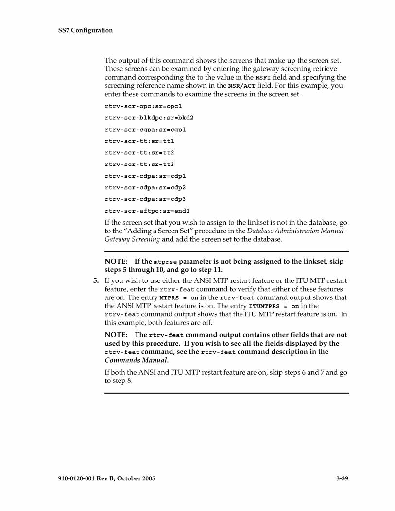
SS7 Configuration
910-0120-001 Rev B, October 2005 3-39
The output of this command shows the screens that make up the screen set. These screens can be examined by entering the gateway screening retrieve command corresponding the to the value in the NSFI field and specifying the screening reference name shown in the NSR/ACT field. For this example, you enter these commands to examine the screens in the screen set.
rtrv-scr-opc:sr=opc1
rtrv-scr-blkdpc:sr=bkd2
rtrv-scr-cgpa:sr=cgp1
rtrv-scr-tt:sr=tt1
rtrv-scr-tt:sr=tt2
rtrv-scr-tt:sr=tt3
rtrv-scr-cdpa:sr=cdp1
rtrv-scr-cdpa:sr=cdp2
rtrv-scr-cdpa:sr=cdp3
rtrv-scr-aftpc:sr=end1
If the screen set that you wish to assign to the linkset is not in the database, go to the “Adding a Screen Set” procedure in the Database Administration Manual - Gateway Screening and add the screen set to the database.
NOTE: If the mtprse parameter is not being assigned to the linkset, skip steps 5 through 10, and go to step 11.
5. If you wish to use either the ANSI MTP restart feature or the ITU MTP restart feature, enter the rtrv-feat command to verify that either of these features are on. The entry MTPRS = on in the rtrv-feat command output shows that the ANSI MTP restart feature is on. The entry ITUMTPRS = on in the rtrv-feat command output shows that the ITU MTP restart feature is on. In this example, both features are off.
NOTE: The rtrv-feat command output contains other fields that are not used by this procedure. If you wish to see all the fields displayed by the rtrv-feat command, see the rtrv-feat command description in the Commands Manual.
If both the ANSI and ITU MTP restart feature are on, skip steps 6 and 7 and go to step 8.

3-40 910-0120-001 Rev B, October 2005
SS7 Configuration
NOTE: If you are not going to turn the ANSI MTP restart feature on, or if the output of the rtrv-feat command in step 5 shows that the ANSI MTP restart feature is on (shown by the MPTRS = on entry), skip this step and go to step 7.
6. Turn the ANSI MTP restart feature on by entering this command.
chg-feat:mtprs=on
NOTE: Once the ANSI MTP restart feature is turned on with the chg-feat command, it cannot be turned off.
The ANSI MTP restart feature must be purchased before you turn the feature on with the chg-feat command. If you are not sure if you have purchased the ANSI MTP restart feature, contact your Tekelec Sales Representative or Account Representative.
When this command has successfully completed, this message should appear.
rlghncxa03w 05-09-10 11:43:04 GMT EAGLE5 34.0.0CHG-FEAT: MASP A - COMPLTD
NOTE: If you are not going to turn the ITU MTP restart feature on, or if the output of the rtrv-feat command in step 5 shows that the ITU MTP restart feature is on (shown by the ITUMPTRS = on entry), skip this step and go to step 8.
7. Turn the ITU MTP restart feature on by entering this command.
chg-feat:itumtprs=on
NOTE: Once the ITU MTP restart feature is turned on with the chg-feat command, it cannot be turned off.
The ITU MTP restart feature must be purchased before you turn the feature on with the chg-feat command. If you are not sure if you have purchased the ITU MTP restart feature, contact your Tekelec Sales Representative or Account Representative.
When this command has successfully completed, this message should appear.
rlghncxa03w 05-09-10 11:43:04 GMT EAGLE5 34.0.0CHG-FEAT: MASP A - COMPLTD

SS7 Configuration
910-0120-001 Rev B, October 2005 3-41
8. Enter the rtrv-stpopts command to display the value of the mtprsi and mtprsit parameters of the chg-stpopts command.
The mptrsi parameter either enables (mtprsi=yes) or disables (mtprsi=no) the MTP restart process on the EAGLE 5 SAS.
The mtprsit parameter (the MTP restart isolation timer) specifies the minimum amount of time that the EAGLE 5 SAS is isolated before the MTP restart process is started. The value of the mtprsit parameter is from 2 to 900 seconds, with a system default value of 5 seconds.
The value of the mtprsi parameter is shown in the MTPRSI field of the rtrv-stpopts command output. The value of the mtprsit parameter is shown in the MTPRSIT field of the rtrv-stpopts command output, and is shown in milliseconds.
This is an example of the possible output.rlghncxa03w 05-09-17 16:02:05 GMT EAGLE5 34.0.0STP OPTIONS-----------------------MTPRSI noMTPRSIT 5000
NOTE: The rtrv-stpopts command output contains other fields that are not used by this procedure. If you wish to see all the fields displayed by the rtrv-stpopts command, see the rtrv-stpopts command description in the Commands Manual.
To change the value of the MTPRSI or the MTPRSIT fields, go to step 9. Otherwise, skip steps 9 and 10 and go to step 11.
9. Enable the MTP restart process on the EAGLE 5 SAS by changing the value of the MTPRSI field of the rtrv-stpopts command output. Enter the chg-stpopts command with the mtprsi parameter.
chg-stpopts:mtprsi=yes
If you wish to change the value of the MTP restart isolation timer, enter chg-stpopts command with the mtprsit parameter.
chg-stpopts:mtprsit=7500
If you wish to change the value of the MTP restart isolation timer and enable the MTP restart process, enter chg-stpopts command with both the mtprsi=yes and mtprsit parameters.
chg-stpopts:mtprsi=yes:mtprsit=7500
For this example, the MTP restart process is enabled and the value of the MTP restart isolation timer is changed.
When the chg-stpopts command has successfully completed, this message should appear.
rlghncxa03w 05-09-07 00:22:57 GMT EAGLE5 34.0.0CHG-STPOPTS: MASP A - COMPLTD

3-42 910-0120-001 Rev B, October 2005
SS7 Configuration
10. Verify the changes using the rtrv-stpopts command. This is an example of the possible output.
rlghncxa03w 05-09-17 16:02:05 GMT EAGLE5 34.0.0STP OPTIONS-----------------------MTPRSI yesMTPRSIT 7500
NOTE: The rtrv-stpopts command output contains other fields that are not used by this procedure. If you wish to see all the fields displayed by the rtrv-stpopts command, see the rtrv-stpopts command description in the Commands Manual.
NOTE: If the slsci and asl8 parameters are not being assigned to the linkset, skip steps 11 through 13, and go to step 14. The slsci and asl8 parameters can be specified only for linksets with ANSI APCs.
NOTE: If the rtrv-stpopts command was performed in steps 8 and 10, skip this step and go to step 12.
11. Display the existing value for the slscnv parameter by entering the rtrv-stpopts command. The value for the slscnv parameter is shown in the SLSCNV field. This is an example of the possible output.
rlghncxa03w 05-09-17 16:02:05 GMT EAGLE5 34.0.0STP OPTIONS-----------------------SLSCNV on
NOTE: The rtrv-stpopts command output contains other fields that are not used by this procedure. If you wish to see all the fields displayed by the rtrv-stpopts command, see the rtrv-stpopts command description in the Commands Manual.
NOTE: If the slscnv parameter is not being changed, skip this step and step 13, and go to step 14.
12. Change the slscnv parameter value using the chg-stpopts command. For this example, the value of the slscnv parameter is being changed from on to perls. Enter this command.
chg-stpopts:slscnv=perls
When this command has successfully completed, this message should appear.
rlghncxa03w 05-09-07 00:22:57 GMT EAGLE5 34.0.0CHG-STPOPTS: MASP A - COMPLTD
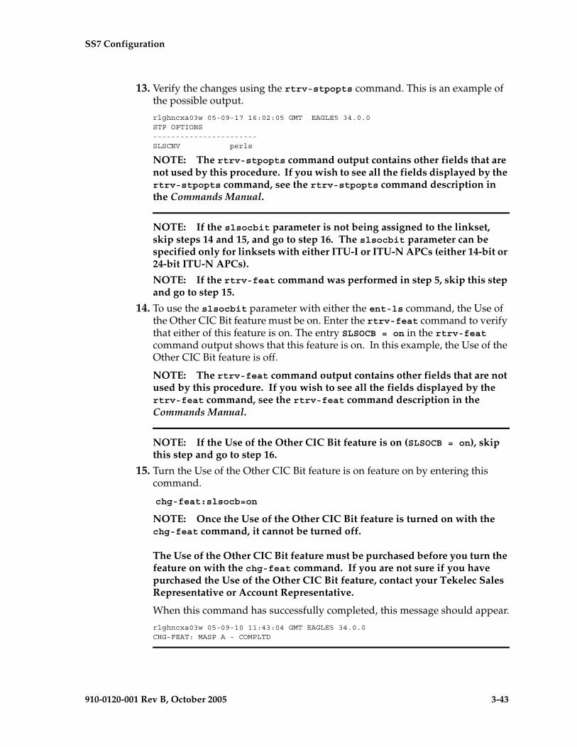
SS7 Configuration
910-0120-001 Rev B, October 2005 3-43
13. Verify the changes using the rtrv-stpopts command. This is an example of the possible output.
rlghncxa03w 05-09-17 16:02:05 GMT EAGLE5 34.0.0STP OPTIONS-----------------------SLSCNV perls
NOTE: The rtrv-stpopts command output contains other fields that are not used by this procedure. If you wish to see all the fields displayed by the rtrv-stpopts command, see the rtrv-stpopts command description in the Commands Manual.
NOTE: If the slsocbit parameter is not being assigned to the linkset, skip steps 14 and 15, and go to step 16. The slsocbit parameter can be specified only for linksets with either ITU-I or ITU-N APCs (either 14-bit or 24-bit ITU-N APCs).
NOTE: If the rtrv-feat command was performed in step 5, skip this step and go to step 15.
14. To use the slsocbit parameter with either the ent-ls command, the Use of the Other CIC Bit feature must be on. Enter the rtrv-feat command to verify that either of this feature is on. The entry SLSOCB = on in the rtrv-feat command output shows that this feature is on. In this example, the Use of the Other CIC Bit feature is off.
NOTE: The rtrv-feat command output contains other fields that are not used by this procedure. If you wish to see all the fields displayed by the rtrv-feat command, see the rtrv-feat command description in the Commands Manual.7
NOTE: If the Use of the Other CIC Bit feature is on (SLSOCB = on), skip this step and go to step 16.
15. Turn the Use of the Other CIC Bit feature is on feature on by entering this command.
chg-feat:slsocb=on
NOTE: Once the Use of the Other CIC Bit feature is turned on with the chg-feat command, it cannot be turned off.
The Use of the Other CIC Bit feature must be purchased before you turn the feature on with the chg-feat command. If you are not sure if you have purchased the Use of the Other CIC Bit feature, contact your Tekelec Sales Representative or Account Representative.
When this command has successfully completed, this message should appear.
rlghncxa03w 05-09-10 11:43:04 GMT EAGLE5 34.0.0CHG-FEAT: MASP A - COMPLTD

3-44 910-0120-001 Rev B, October 2005
SS7 Configuration
NOTE: If the multgc=yes parameter is not being assigned to the linkset, skip steps 16, and 17, and go to step 18. The multgc=yes parameter can be specified only for linksets with either ITU-I or 14-bit ITU-N APCs, and linksets that will contain signaling links running the IPLIMI applications.
NOTE: If the rtrv-feat command was performed in steps 5 or 14, skip this step and go to step 17.
16. To specify the multgc=yes parameter with the ent-ls command, the ITU Duplicate Point Code feature must be on. For the ITU Duplicate Point Code feature to be on, the Multiple Point Code feature must be on. Enter the rtrv-feat command to verify that either of these features are on. The entry MPC = on in the rtrv-feat command output shows that the Multiple Point Code feature is on. The entry ITUDUPPC = on in the rtrv-feat command output shows that the ITU Duplicate Point Code feature is on. In this example, both features are off.
NOTE: The rtrv-feat command output contains other fields that are not used by this procedure. If you wish to see all the fields displayed by the rtrv-feat command, see the rtrv-feat command description in the Commands Manual.7
NOTE: If the ITU Duplicate Point Code feature is on (ITUDUPPC = on), skip this step and go to step 18.
17. Turn the ITU Duplicate Point Code feature on, and the Multiple Point Code feature if necessary, by entering one of these commands.
To turn the ITU Duplicate Point Code feature on only.
chg-feat:ituduppc=on
To turn both the ITU Duplicate Point Code and Multiple Point Code features on.
chg-feat:mpc=on:ituduppc=on
NOTE: Once the ITU Duplicate Point Code and Multiple Point Code features are turned on with the chg-feat command, they cannot be turned off.
The ITU Duplicate Point Code and Multiple Point Code features must be purchased before you turn either of these features on with the chg-feat command. If you are not sure if you have purchased these features, contact your Tekelec Sales Representative or Account Representative.
When this command has successfully completed, this message should appear.
rlghncxa03w 05-09-10 11:43:04 GMT EAGLE5 34.0.0CHG-FEAT: MASP A - COMPLTD

SS7 Configuration
910-0120-001 Rev B, October 2005 3-45
18. Using the outputs from steps 1 through 17, Table 3-2 on page 3-19, and Table 3-6 on page 3-35 as a guide, add the new linkset to the database using the ent-ls command. The new linkset must meet these conditions.
• The new linkset cannot already be in the database – the linkset configuration is shown in the output of step 1.
• The APC of the new linkset must be in the destination point code table, but cannot be either the EAGLE 5 SAS’s point code or the EAGLE 5 SAS’s capability point code – shown in the outputs of steps 2 and 3.
• If a gateway screening screen set is assigned to the linkset, the gateway screening screen set must be in the database – shown in the output of step 4.
• The gwsa, gwsm, and gwsd parameters can be specified only if the scrn parameter is specified.
CAUTION: When Gateway Screening is in the screen test mode, as defined by the linkset parameters gwsa=off and gwsm=on, the gateway screening action in the gateway screening stop action set specified by the actname parameter of the gateway screening screen set at the end of the gateway screening process will be performed.
• The gwsd=on parameter can be specified only with the gwsa=on parameter.
• See Table 3-4 on page 3-27 for the combinations of the asl8 and slsci parameters, and the slscnv STP option, and the results that these combinations produce. The asl8 and slsci parameters can be specified only for linksets with ANSI APCs.
• The nis=on parameter cannot be specified for linksets with ITU-I adjacent point codes.
• The multgc=yes parameter can be specified only for linksets with either ITU-I or 14-bit ITU-N APCs, and for linksets that will contain signaling links running the IPLIMI application.
• The itutfr=on parameter can be specified only for linksets with ITU-N APCs (either 14-bit or 24-bit ITU-N APCs).
• Private point codes cannot be used as an adjacent point code in this procedure. Private point codes can be assigned only to IPGWx linksets. The procedures for configuring IPGWx linksets is in the Database Administration Manual - IP7 Secure Gateway.
• The apcntype parameter can be used only with 14-bit ITU-N or 24-bit ITU-N adjacent point codes.
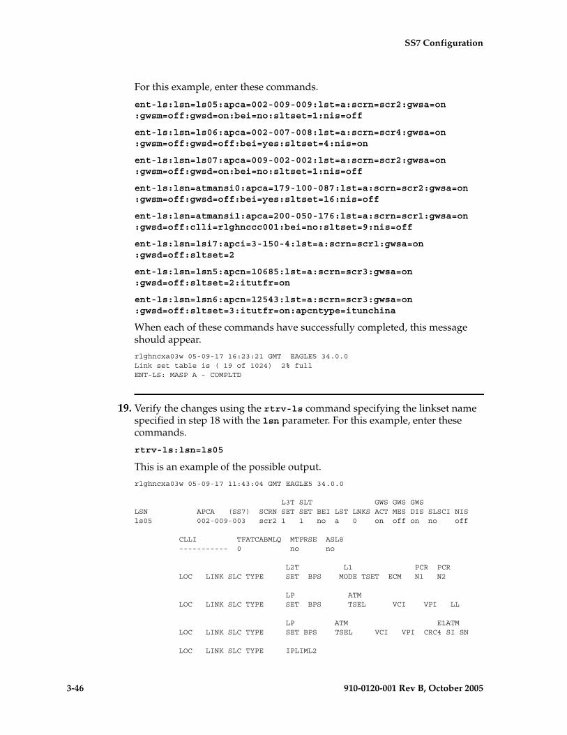
3-46 910-0120-001 Rev B, October 2005
SS7 Configuration
For this example, enter these commands.
ent-ls:lsn=ls05:apca=002-009-009:lst=a:scrn=scr2:gwsa=on:gwsm=off:gwsd=on:bei=no:sltset=1:nis=off
ent-ls:lsn=ls06:apca=002-007-008:lst=a:scrn=scr4:gwsa=on:gwsm=off:gwsd=off:bei=yes:sltset=4:nis=on
ent-ls:lsn=ls07:apca=009-002-002:lst=a:scrn=scr2:gwsa=on:gwsm=off:gwsd=on:bei=no:sltset=1:nis=off
ent-ls:lsn=atmansi0:apca=179-100-087:lst=a:scrn=scr2:gwsa=on:gwsm=off:gwsd=off:bei=yes:sltset=16:nis=off
ent-ls:lsn=atmansi1:apca=200-050-176:lst=a:scrn=scr1:gwsa=on:gwsd=off:clli=rlghnccc001:bei=no:sltset=9:nis=off
ent-ls:lsn=lsi7:apci=3-150-4:lst=a:scrn=scr1:gwsa=on:gwsd=off:sltset=2
ent-ls:lsn=lsn5:apcn=10685:lst=a:scrn=scr3:gwsa=on:gwsd=off:sltset=2:itutfr=on
ent-ls:lsn=lsn6:apcn=12543:lst=a:scrn=scr3:gwsa=on:gwsd=off:sltset=3:itutfr=on:apcntype=itunchina
When each of these commands have successfully completed, this message should appear.
rlghncxa03w 05-09-17 16:23:21 GMT EAGLE5 34.0.0Link set table is ( 19 of 1024) 2% fullENT-LS: MASP A - COMPLTD
19. Verify the changes using the rtrv-ls command specifying the linkset name specified in step 18 with the lsn parameter. For this example, enter these commands.
rtrv-ls:lsn=ls05
This is an example of the possible output.
rlghncxa03w 05-09-17 11:43:04 GMT EAGLE5 34.0.0
L3T SLT GWS GWS GWSLSN APCA (SS7) SCRN SET SET BEI LST LNKS ACT MES DIS SLSCI NISls05 002-009-003 scr2 1 1 no a 0 on off on no off
CLLI TFATCABMLQ MTPRSE ASL8 ----------- 0 no no
L2T L1 PCR PCR LOC LINK SLC TYPE SET BPS MODE TSET ECM N1 N2
LP ATM LOC LINK SLC TYPE SET BPS TSEL VCI VPI LL
LP ATM E1ATM LOC LINK SLC TYPE SET BPS TSEL VCI VPI CRC4 SI SN
LOC LINK SLC TYPE IPLIML2
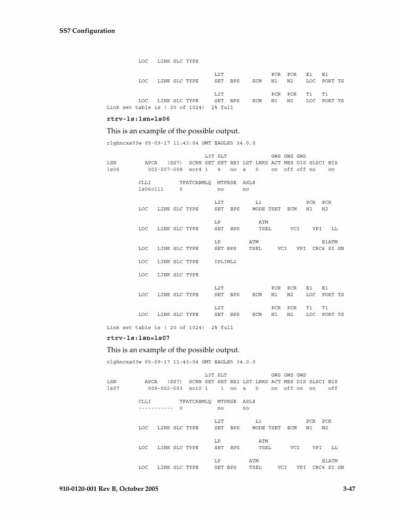
SS7 Configuration
910-0120-001 Rev B, October 2005 3-47
LOC LINK SLC TYPE
L2T PCR PCR E1 E1 LOC LINK SLC TYPE SET BPS ECM N1 N2 LOC PORT TS
L2T PCR PCR T1 T1 LOC LINK SLC TYPE SET BPS ECM N1 N2 LOC PORT TSLink set table is ( 20 of 1024) 2% full
rtrv-ls:lsn=ls06
This is an example of the possible output.
rlghncxa03w 05-09-17 11:43:04 GMT EAGLE5 34.0.0
L3T SLT GWS GWS GWSLSN APCA (SS7) SCRN SET SET BEI LST LNKS ACT MES DIS SLSCI NISls06 002-007-008 scr4 1 4 no a 0 on off off no on
CLLI TFATCABMLQ MTPRSE ASL8 ls06clli 0 no no
L2T L1 PCR PCR LOC LINK SLC TYPE SET BPS MODE TSET ECM N1 N2
LP ATM LOC LINK SLC TYPE SET BPS TSEL VCI VPI LL
LP ATM E1ATM LOC LINK SLC TYPE SET BPS TSEL VCI VPI CRC4 SI SN
LOC LINK SLC TYPE IPLIML2
LOC LINK SLC TYPE
L2T PCR PCR E1 E1 LOC LINK SLC TYPE SET BPS ECM N1 N2 LOC PORT TS
L2T PCR PCR T1 T1 LOC LINK SLC TYPE SET BPS ECM N1 N2 LOC PORT TS
Link set table is ( 20 of 1024) 2% full
rtrv-ls:lsn=ls07
This is an example of the possible output.
rlghncxa03w 05-09-17 11:43:04 GMT EAGLE5 34.0.0
L3T SLT GWS GWS GWSLSN APCA (SS7) SCRN SET SET BEI LST LNKS ACT MES DIS SLSCI NISls07 009-002-003 scr2 1 1 no a 0 on off on no off
CLLI TFATCABMLQ MTPRSE ASL8 ----------- 0 no no
L2T L1 PCR PCR LOC LINK SLC TYPE SET BPS MODE TSET ECM N1 N2
LP ATM LOC LINK SLC TYPE SET BPS TSEL VCI VPI LL
LP ATM E1ATM LOC LINK SLC TYPE SET BPS TSEL VCI VPI CRC4 SI SN

3-48 910-0120-001 Rev B, October 2005
SS7 Configuration
LOC LINK SLC TYPE IPLIML2
LOC LINK SLC TYPE
L2T PCR PCR E1 E1 LOC LINK SLC TYPE SET BPS ECM N1 N2 LOC PORT TS
L2T PCR PCR T1 T1 LOC LINK SLC TYPE SET BPS ECM N1 N2 LOC PORT TS
Link set table is ( 20 of 1024) 2% full
rtrv-ls:lsn=atmansi0
This is an example of the possible output.
rlghncxa03w 05-09-17 11:43:04 GMT EAGLE5 34.0.0
L3T SLT GWS GWS GWSLSN APCA (SS7) SCRN SET SET BEI LST LNKS ACT MES DIS SLSCI NISatmansi0 179-100-087 scr2 1 16 yes a 0 on off off no off
CLLI TFATCABMLQ MTPRSE ASL8 ----------- 0 no no
L2T L1 PCR PCR LOC LINK SLC TYPE SET BPS MODE TSET ECM N1 N2
LP ATM LOC LINK SLC TYPE SET BPS TSEL VCI VPI LL
LP ATM E1ATM LOC LINK SLC TYPE SET BPS TSEL VCI VPI CRC4 SI SN
LOC LINK SLC TYPE IPLIML2
LOC LINK SLC TYPE
L2T PCR PCR E1 E1 LOC LINK SLC TYPE SET BPS ECM N1 N2 LOC PORT TS
L2T PCR PCR T1 T1 LOC LINK SLC TYPE SET BPS ECM N1 N2 LOC PORT TS
Link set table is ( 20 of 1024) 2% full
rtrv-ls:lsn=atmansi1
This is an example of the possible output.
rlghncxa03w 05-09-17 11:43:04 GMT EAGLE5 34.0.0
L3T SLT GWS GWS GWSLSN APCA (SS7) SCRN SET SET BEI LST LNKS ACT MES DIS SLSCI NISatmansi1 200-050-176 scr1 1 9 no a 0 on off off no off
CLLI TFATCABMLQ MTPRSE ASL8 rlghnccc001 0 no no
L2T L1 PCR PCR LOC LINK SLC TYPE SET BPS MODE TSET ECM N1 N2

SS7 Configuration
910-0120-001 Rev B, October 2005 3-49
LP ATM LOC LINK SLC TYPE SET BPS TSEL VCI VPI LL
LP ATM E1ATM LOC LINK SLC TYPE SET BPS TSEL VCI VPI CRC4 SI SN
LOC LINK SLC TYPE IPLIML2
LOC LINK SLC TYPE
L2T PCR PCR E1 E1 LOC LINK SLC TYPE SET BPS ECM N1 N2 LOC PORT TS
L2T PCR PCR T1 T1 LOC LINK SLC TYPE SET BPS ECM N1 N2 LOC PORT TS
Link set table is ( 20 of 1024) 2% full
rtrv-ls:lsn=lsi7
This is an example of the possible output.
rlghncxa03w 05-09-17 11:43:04 GMT EAGLE5 34.0.0
L3T SLT GWS GWS GWSLSN APCI (SS7) SCRN SET SET BEI LST LNKS ACT MES DIS SLSCI NISlsi7 3-150-4 scr1 1 2 no a 0 on off off no off
CLLI TFATCABMLQ MTPRSE ASL8 SLSOCBIT SLSRSB GSMSCRN lsi7clli 1 no no none 1 off
L2T L1 PCR PCR LOC LINK SLC TYPE SET BPS MODE TSET ECM N1 N2
LP ATM LOC LINK SLC TYPE SET BPS TSEL VCI VPI LL
LP ATM E1ATM LOC LINK SLC TYPE SET BPS TSEL VCI VPI CRC4 SI SN
LOC LINK SLC TYPE IPLIML2
LOC LINK SLC TYPE
L2T PCR PCR E1 E1 LOC LINK SLC TYPE SET BPS ECM N1 N2 LOC PORT TS
L2T PCR PCR T1 T1 LOC LINK SLC TYPE SET BPS ECM N1 N2 LOC PORT TS
Link set table is ( 20 of 1024) 2% full

3-50 910-0120-001 Rev B, October 2005
SS7 Configuration
rtrv-ls:lsn=lsn5
This is an example of the possible output.
rlghncxa03w 05-09-17 11:43:04 GMT EAGLE5 34.0.0
L3T SLT GWS GWS GWSLSN APCN (SS7) SCRN SET SET BEI LST LNKS ACT MES DIS SLSCI NISlsn5 10685 scr3 1 2 no a 0 on off off no off
CLLI TFATCABMLQ MTPRSE ASL8 SLSOCBIT SLSRSB ITUTFR lsn5clli 1 --- --- none 1 on
GSMSCRN on
IPGWAPC MATELSN IPTPS LSUSEALM SLKUSEALM no ---------- --- --- ---
L2T L1 PCR PCR LOC LINK SLC TYPE SET BPS MODE TSET ECM N1 N2
LP ATM LOC LINK SLC TYPE SET BPS TSEL VCI VPI LL
LP ATM E1ATM LOC LINK SLC TYPE SET BPS TSEL VCI VPI CRC4 SI SN
LOC LINK SLC TYPE IPLIML2
LOC LINK SLC TYPE
L2T PCR PCR E1 E1 LOC LINK SLC TYPE SET BPS ECM N1 N2 LOC PORT TS
L2T PCR PCR T1 T1 LOC LINK SLC TYPE SET BPS ECM N1 N2 LOC PORT TS
Link set table is ( 20 of 1024) 2% full
rtrv-ls:lsn=lsn6
This is an example of the possible output.
rlghncxa03w 05-09-17 11:43:04 GMT EAGLE5 34.0.0
L3T SLT GWS GWS GWSLSN (CHINA) APCN (SS7) SCRN SET SET BEI LST LNKS ACT MES DIS SLSCI NISlsn6 12543 scr3 1 3 no A 0 on off off --- off
CLLI TFATCABMLQ MTPRSE ASL8 SLSOCBIT SLSRSB ITUTFR ----------- 1 --- --- none 1 on
GSMSCRN off
IPGWAPC MATELSN IPTPS LSUSEALM SLKUSEALM no ---------- --- --- --- L2T L1 PCR PCR LOC LINK SLC TYPE SET BPS MODE TSET ECM N1 N2
LP ATM LOC LINK SLC TYPE SET BPS TSEL VCI VPI LL

SS7 Configuration
910-0120-001 Rev B, October 2005 3-51
LP ATM E1ATM LOC LINK SLC TYPE SET BPS TSEL VCI VPI CRC4 SI SN
LOC LINK SLC TYPE IPLIML2
LOC LINK SLC TYPE
L2T PCR PCR E1 E1 LOC LINK SLC TYPE SET BPS ECM N1 N2 LOC PORT TS
L2T PCR PCR T1 T1 LOC LINK SLC TYPE SET BPS ECM N1 N2 LOC PORT TS
Link set table is ( 20 of 1024) 2% full
20. Back up the new changes using the chg-db:action=backup:dest=fixed command. These messages should appear, the active Maintenance and Administration Subsystem Processor (MASP) appears first.
BACKUP (FIXED) : MASP A - Backup starts on active MASP.BACKUP (FIXED) : MASP A - Backup on active MASP to fixed disk complete.BACKUP (FIXED) : MASP A - Backup starts on standby MASP.BACKUP (FIXED) : MASP A - Backup on standby MASP to fixed disk complete.
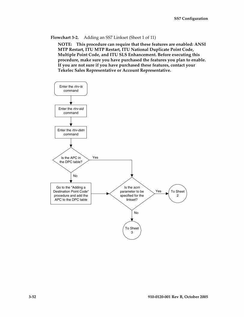
3-52 910-0120-001 Rev B, October 2005
SS7 Configuration
Flowchart 3-2. Adding an SS7 Linkset (Sheet 1 of 11)
NOTE: This procedure can require that these features are enabled: ANSI MTP Restart, ITU MTP Restart, ITU National Duplicate Point Code, Multiple Point Code, and ITU SLS Enhancement. Before executing this procedure, make sure you have purchased the features you plan to enable. If you are not sure if you have purchased these features, contact your Tekelec Sales Representative or Account Representative.
Is the APC inthe DPC table?
Enter the rtrv-dstncommand
No
Yes
Enter the rtrv-lscommand
Go to the "Adding aDestination Point Code"procedure and add theAPC to the DPC table
Enter the rtrv-sidcommand
To Sheet2
Is the scrnparameter to bespecified for the
linkset?
Yes
No
To Sheet3
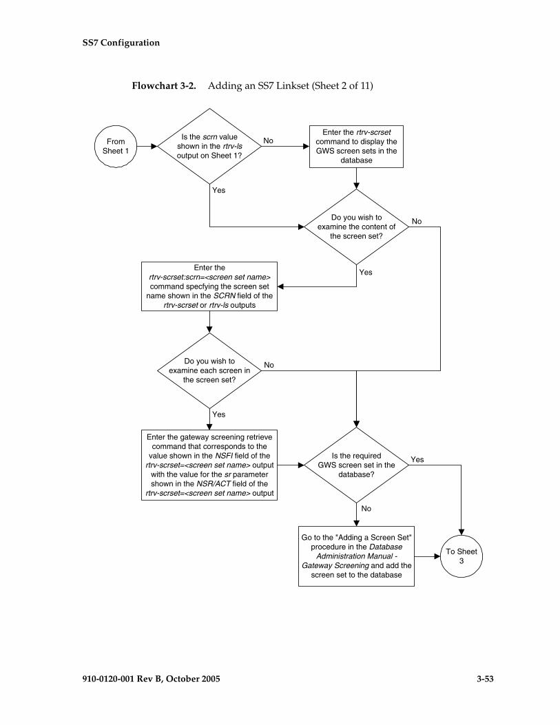
SS7 Configuration
910-0120-001 Rev B, October 2005 3-53
Flowchart 3-2. Adding an SS7 Linkset (Sheet 2 of 11)
To Sheet3
Go to the "Adding a Screen Set"procedure in the Database
Administration Manual -Gateway Screening and add the
screen set to the database
Yes
Enter the rtrv-scrsetcommand to display theGWS screen sets in the
database
Is the requiredGWS screen set in the
database?
No
FromSheet 1
Do you wish toexamine the content of
the screen set?
Enter thertrv-scrset:scrn=<screen set name>command specfying the screen set
name shown in the SCRN field of thertrv-scrset or rtrv-ls outputs
Do you wish toexamine each screen in
the screen set?
Enter the gateway screening retrievecommand that corresponds to the
value shown in the NSFI field of thertrv-scrset=<screen set name> output
with the value for the sr parametershown in the NSR/ACT field of the
rtrv-scrset=<screen set name> output
Yes
Yes
No
No
Is the scrn valueshown in the rtrv-lsoutput on Sheet 1?
Yes
No

3-54 910-0120-001 Rev B, October 2005
SS7 Configuration
Flowchart 3-2. Adding an SS7 Linkset (Sheet 3 of 11)
Do you wish touse the ANSI MTP
restart feature?(See Note 2)
Enter the rtrv-featcommand
No
Yes
Is the ANSI MTPrestart feature on?
Enter thechg-feat:mtprs=on
command
Is the ITU MTPrestart feature on?
Enter thechg-feat:itumtprs=on
command
ToSheet 4
Yes
Yes
No
No
Do you wish touse the ITU MTPrestart feature?
(See Note 3)
Yes
No
FromSheet 2
Is the mtprse=yesparameter to be specified
for the linkset?(See Note 1)
No
Yes
ToSheet 5
Notes:
1. If the ipliml2=m3ua parameter is to bespecified for the signaling links that will beassigned to the linkset, the value of the mtprseparameter must be no.
2.The ANSI MTP restart feature can be used onlywith linksets that have ANSI APCs.
3.The ITU MTP restart feature can be used onlywith linksets that have either ITU-I or ITU-NAPCs (either 14-bit or 24-bit ITU-N APCs).
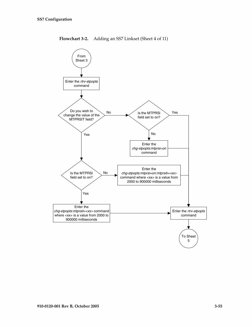
SS7 Configuration
910-0120-001 Rev B, October 2005 3-55
Flowchart 3-2. Adding an SS7 Linkset (Sheet 4 of 11)
Do you wish tochange the value of the
MTPRSIT field?
No
Yes
Is the MTPRSIfield set to on?
Yes
No
FromSheet 3
Enter the rtrv-stpoptscommand
To Sheet5
Is the MTPRSIfield set to on?
Enter thechg-stpopts:mtprsi=on
command
Enter thechg-stpopts:mtprsit=<xx> commandwhere <xx> is a value from 2000 to
900000 milliseconds
Enter thechg-stpopts:mtprsi=on:mtprsit=<xx>
command where <xx> is a value from2000 to 900000 milliseconds
Enter the rtrv-stpoptscommand
Yes
No
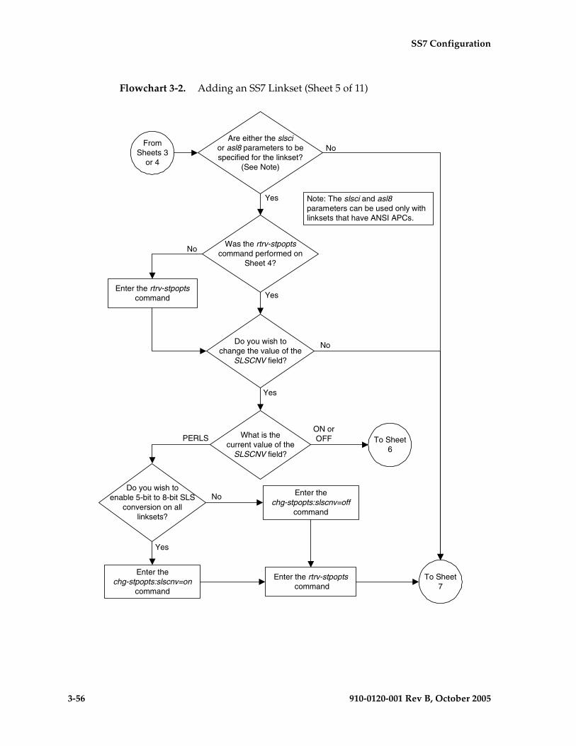
3-56 910-0120-001 Rev B, October 2005
SS7 Configuration
Flowchart 3-2. Adding an SS7 Linkset (Sheet 5 of 11)
What is thecurrent value of the
SLSCNV field?
Enter the rtrv-stpoptscommand
Do you wish toenable 5-bit to 8-bit SLS
conversion on alllinksets?
To Sheet6
Yes
No Enter thechg-stpopts:slscnv=off
command
Enter thechg-stpopts:slscnv=on
command
Enter the rtrv-stpopts command
PERLS
Do you wish tochange the value of the
SLSCNV field?
To Sheet7
No
Yes
ON orOFF
FromSheets 3
or 4
Are either the slscior asl8 parameters to bespecified for the linkset?
(See Note)
No
Yes Note: The slsci and asl8parameters can be used only withlinksets that have ANSI APCs.
Was the rtrv-stpoptscommand performed on
Sheet 4?
Yes
No

SS7 Configuration
910-0120-001 Rev B, October 2005 3-57
Flowchart 3-2. Adding an SS7 Linkset (Sheet 6 of 11)
Do you wish toenable 5-bit to 8-bit SLS
conversion only on specificlinksets?
Yes
Enter thechg-stpopts:slscnv=off
command
Enter thechg-stpopts:slscnv=perls
command
Enter the rtrv-stpopts command
FromSheet 5
No
Do you wish toenable 5-bit to 8-bit SLS
conversion on alllinksets?
Yes
Enter thechg-stpopts:slscnv=perls
command
Enter thechg-stpopts:slscnv=on
command
NoIs the value of theSLSCNV parameter on
or off?
On
Off
To Sheet 7

3-58 910-0120-001 Rev B, October 2005
SS7 Configuration
Flowchart 3-2. Adding an SS7 Linkset (Sheet 7 of 11)
Is the ITU SLSEnhancement feature
on (SLSOCB=on)?
Enter the rtrv-featcommand
Enter thechg-feat:slsocb=on
command
Is the slsocbitparameter to be assigned
to the linkset?
FromSheets 5
or 6
Yes
No
To Sheet8
Yes
No
Is the slsocbitparameter to be specified
for the linkset?(See Note)
No
Yes
To Sheet8
Note: The slsocbit parameter canbe used only with linksets that haveeither ITU-I or ITU-N APCs (either14-bit or 24-bit ITU-N APCs).
Was the rtrv-featcommand performed on
Sheet 3?
Yes
No

SS7 Configuration
910-0120-001 Rev B, October 2005 3-59
Flowchart 3-2. Adding an SS7 Linkset (Sheet 8 of 11)
Is the MutiplePoint Code feature on
(MPC = on)?
Is the ITUNational Duplicate Point
Code feature on(ITUDUPPC = on)?
Does the rtrv-lsoutput show any ITU-Npoint codes with group
codes?
Is the MULTGCparameter to be assigned to
the linkset? (See Notes 1and 2)
Enter thechg-feat:mpc=on
:ituduppc=on command
Enter thechg-feat:ituduppc=on
command
Enter the rtrv-featcommand
Yes
No
No
No
Yes
Yes
Yes
No
Notes:
1. The application assigned to the signaling links in thelinkset must be IPLIMI.
2. The multgc=yes parameter can only be specified forlinksets with either an ITU-I or a 14-bit ITU-N APC.
FromSheet 7
ToSheet 9
Was the rtrv-featcommand performed on
Sheets 3 or 7?
Yes
No
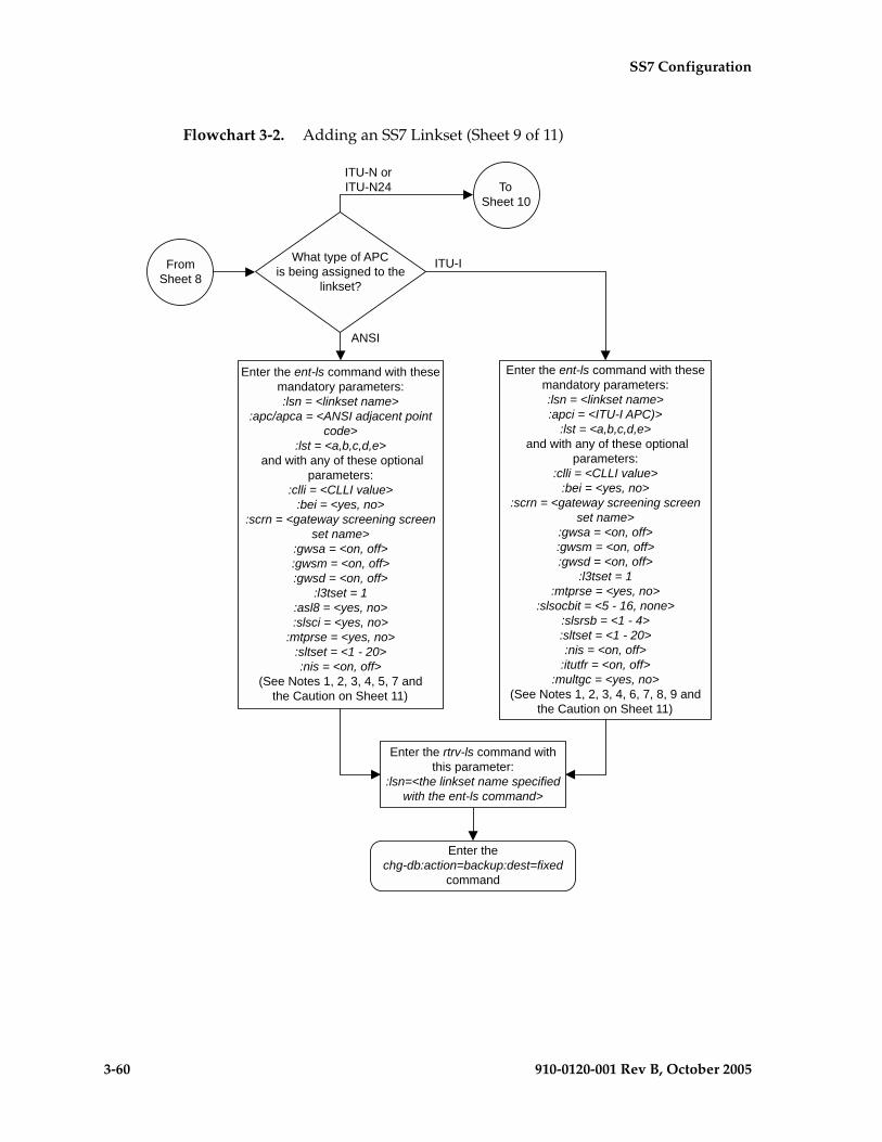
3-60 910-0120-001 Rev B, October 2005
SS7 Configuration
Flowchart 3-2. Adding an SS7 Linkset (Sheet 9 of 11)
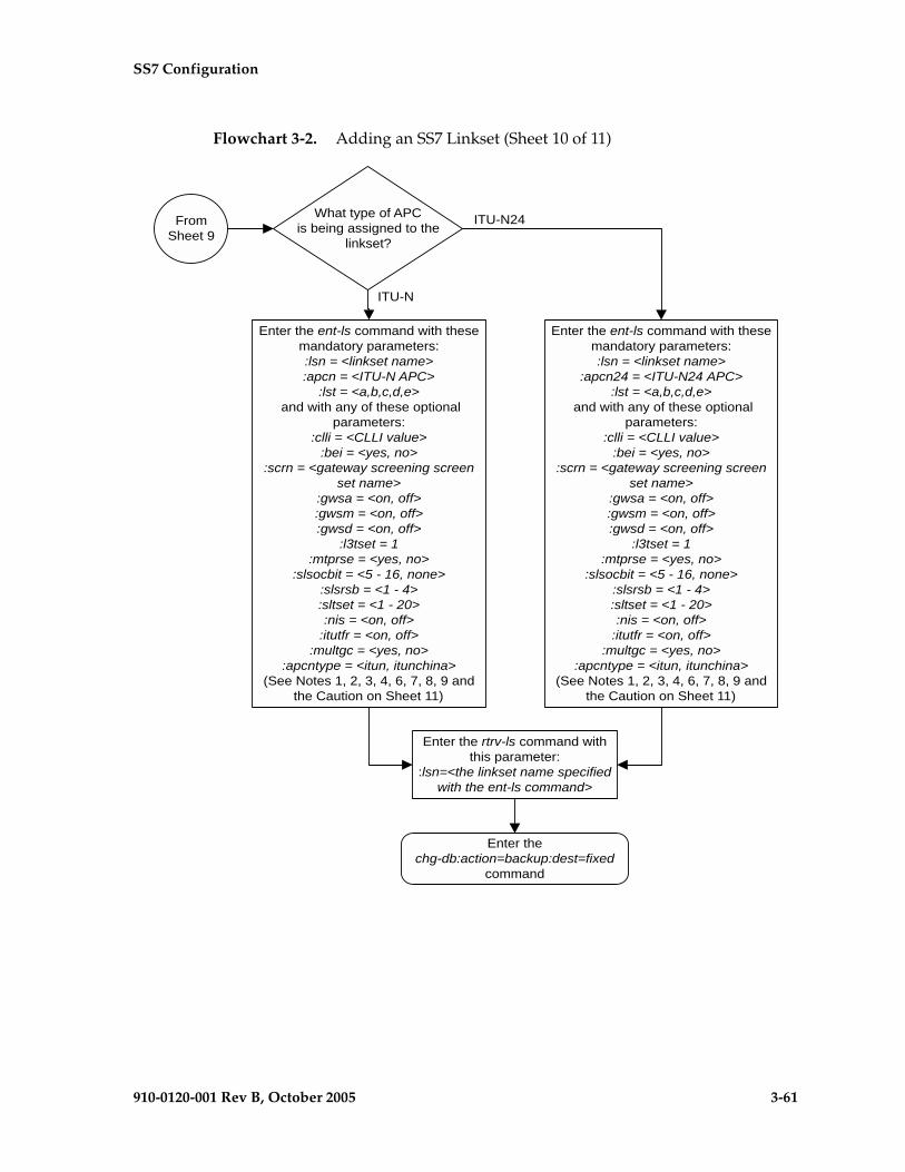
SS7 Configuration
910-0120-001 Rev B, October 2005 3-61
Flowchart 3-2. Adding an SS7 Linkset (Sheet 10 of 11)

3-62 910-0120-001 Rev B, October 2005
SS7 Configuration
Flowchart 3-2. Adding an SS7 Linkset (Sheet 11 of 11)
Notes:
1. The adjacent point code must be a full point code, cannot be an alias point code,and must be shown in the rtrv-dstn output. Private point codes cannot be used as anadjacent point code in this procedure. Private point codes can be assigned only toIPGWx linksets. The procedures for configuring IPGWx linksets are in the DatabaseAdministration Manual - IP7 Secure Gateway.
2. The adjacent point code cannot be shown in the rtrv-sid output as the system'spoint code or any capability point codes.
3. The gwsa, gwsm, and gwsd parameters can be specified only if the scrnparameter is specified.
4. The gwsd=on parameter can be specified only with the gwsa=on parameter.
5. See the Signaling Link Selector (SLS) Conversion (ANSI Linksets Only) table inthis procedure for the combinations of the asl8 and slsci parameters, and the slscnvSTP option, and the results that these combinations produce.
6. The nis=on parameter cannot be specified for linksets with ITU-I adjacent pointcodes.
7. The mtprse=yes parameter cannot be specified if the linkset will contain signalinglinks with the iplim2=m3ua parameter assigned.
8. The multgc=yes parameter can be specified only if the linkset being added willcontain signaling links assigned to the IPLIMI application, and only for linksets withITU-I or 14-bit ITU-N APCs.
9. The itutfr=on parameter can be specified only for linksets with ITU-N adjacentpoint codes (either 14-bit or 24-bit ITU-N APCs).
Caution: When Gateway Screening is in the screen test mode, as defined by thelinkset parameters gwsa=off and gwsm=on, the gateway screening action in thegateway screening stop action set specified by the actname parameter of thegateway screening screen set at the end of the gateway screening process will beperformed.

SS7 Configuration
910-0120-001 Rev B, October 2005 3-63
Removing a Linkset Containing SS7 Signaling Links
This procedure is used to remove a linkset containing SS7 signaling links from the database using the dlt-ls command. To remove linkset with X.25 signaling links, go to the “Removing a Linkset Containing X.25 Signaling Links” procedure in the Database Administration Manual – Features.
The dlt-ls command has only one parameter, lsn, which is the name of the linkset to be removed from the database.
The linkset to be removed must exist in the database.
To remove a linkset, all links associated with the linkset must be removed.
The linkset to be removed cannot be referenced by a routeset.
To remove an IPGWx linkset, a linkset containing signaling links assigned to cards running either the SS7IPGW or IPGWI applications, the IPGWx linkset cannot be the mate of another IPGWx linkset.
Canceling the RTRV-LS Command
Because the rtrv-ls command used in this procedure can output information for a long period of time, the rtrv-ls command can be canceled and the output to the terminal stopped. There are three ways that the rtrv-ls command can be canceled.
• Press the F9 function key on the keyboard at the terminal where the rtrv-ls command was entered.
• Enter the canc-cmd without the trm parameter at the terminal where the rtrv-ls command was entered.
• Enter the canc-cmd:trm=<xx>, where <xx> is the terminal where the rtrv-ls command was entered, from another terminal other that the terminal where the rtrv-ls command was entered. To enter the canc-cmd:trm=<xx> command, the terminal must allow Security Administration commands to be entered from it and the user must be allowed to enter Security Administration commands. The terminal’s permissions can be verified with the rtrv-secu-trm command. The user’s permissions can be verified with the rtrv-user or rtrv-secu-user commands.
For more information about the canc-cmd command, go to the Commands Manual.
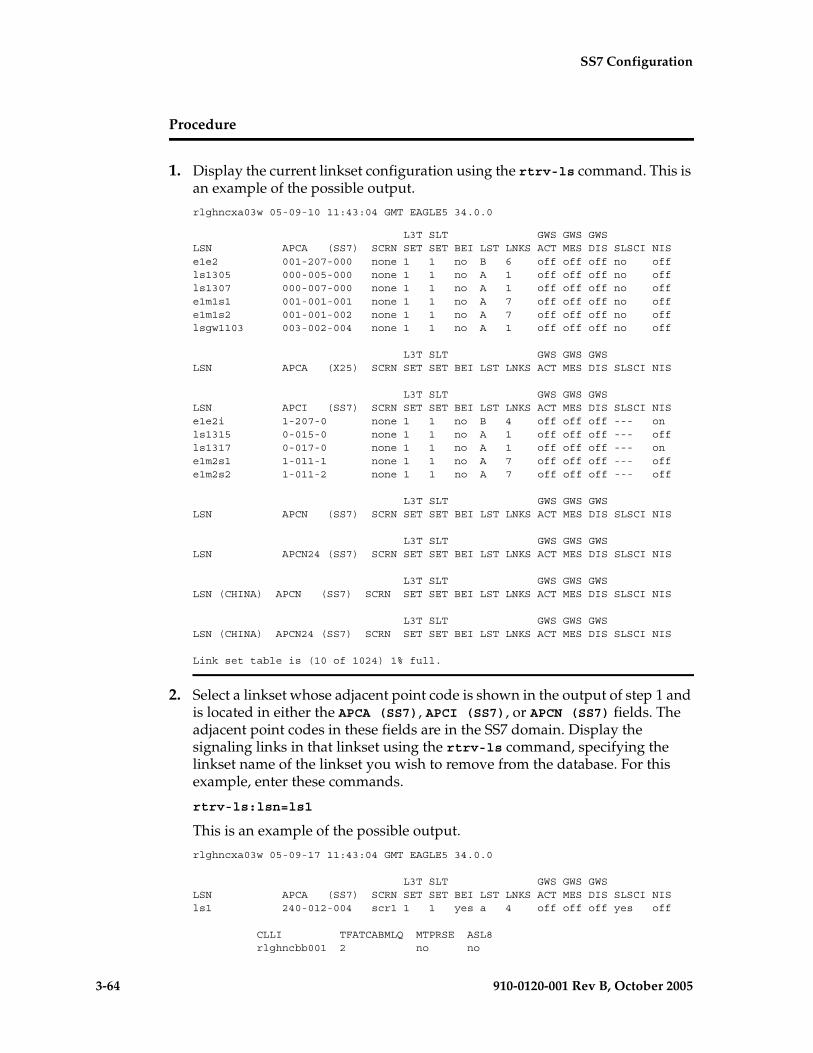
3-64 910-0120-001 Rev B, October 2005
SS7 Configuration
Procedure
1. Display the current linkset configuration using the rtrv-ls command. This is an example of the possible output.
rlghncxa03w 05-09-10 11:43:04 GMT EAGLE5 34.0.0
L3T SLT GWS GWS GWSLSN APCA (SS7) SCRN SET SET BEI LST LNKS ACT MES DIS SLSCI NISe1e2 001-207-000 none 1 1 no B 6 off off off no offls1305 000-005-000 none 1 1 no A 1 off off off no offls1307 000-007-000 none 1 1 no A 1 off off off no offe1m1s1 001-001-001 none 1 1 no A 7 off off off no offe1m1s2 001-001-002 none 1 1 no A 7 off off off no offlsgw1103 003-002-004 none 1 1 no A 1 off off off no off
L3T SLT GWS GWS GWSLSN APCA (X25) SCRN SET SET BEI LST LNKS ACT MES DIS SLSCI NIS
L3T SLT GWS GWS GWSLSN APCI (SS7) SCRN SET SET BEI LST LNKS ACT MES DIS SLSCI NISe1e2i 1-207-0 none 1 1 no B 4 off off off --- onls1315 0-015-0 none 1 1 no A 1 off off off --- offls1317 0-017-0 none 1 1 no A 1 off off off --- one1m2s1 1-011-1 none 1 1 no A 7 off off off --- offe1m2s2 1-011-2 none 1 1 no A 7 off off off --- off
L3T SLT GWS GWS GWSLSN APCN (SS7) SCRN SET SET BEI LST LNKS ACT MES DIS SLSCI NIS
L3T SLT GWS GWS GWSLSN APCN24 (SS7) SCRN SET SET BEI LST LNKS ACT MES DIS SLSCI NIS
L3T SLT GWS GWS GWSLSN (CHINA) APCN (SS7) SCRN SET SET BEI LST LNKS ACT MES DIS SLSCI NIS
L3T SLT GWS GWS GWSLSN (CHINA) APCN24 (SS7) SCRN SET SET BEI LST LNKS ACT MES DIS SLSCI NIS
Link set table is (10 of 1024) 1% full.
2. Select a linkset whose adjacent point code is shown in the output of step 1 and is located in either the APCA (SS7), APCI (SS7), or APCN (SS7) fields. The adjacent point codes in these fields are in the SS7 domain. Display the signaling links in that linkset using the rtrv-ls command, specifying the linkset name of the linkset you wish to remove from the database. For this example, enter these commands.
rtrv-ls:lsn=ls1
This is an example of the possible output.
rlghncxa03w 05-09-17 11:43:04 GMT EAGLE5 34.0.0
L3T SLT GWS GWS GWSLSN APCA (SS7) SCRN SET SET BEI LST LNKS ACT MES DIS SLSCI NISls1 240-012-004 scr1 1 1 yes a 4 off off off yes off
CLLI TFATCABMLQ MTPRSE ASL8 rlghncbb001 2 no no
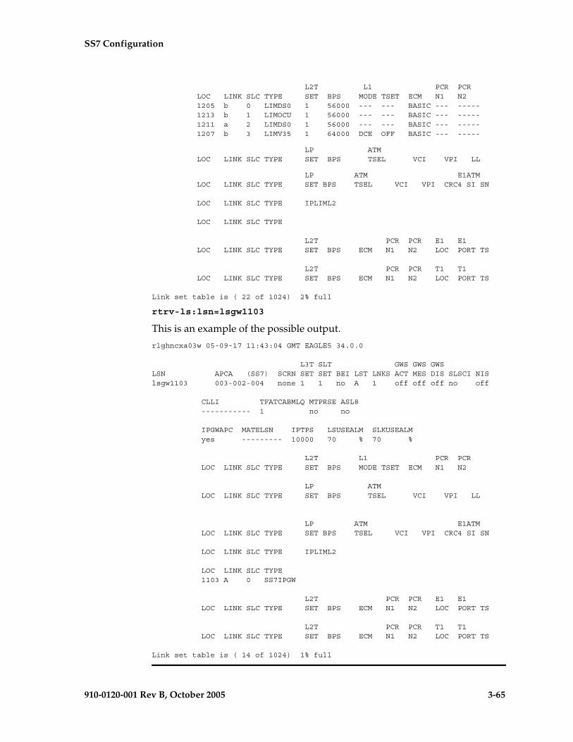
SS7 Configuration
910-0120-001 Rev B, October 2005 3-65
L2T L1 PCR PCR LOC LINK SLC TYPE SET BPS MODE TSET ECM N1 N2 1205 b 0 LIMDS0 1 56000 --- --- BASIC --- ----- 1213 b 1 LIMOCU 1 56000 --- --- BASIC --- ----- 1211 a 2 LIMDS0 1 56000 --- --- BASIC --- ----- 1207 b 3 LIMV35 1 64000 DCE OFF BASIC --- -----
LP ATM LOC LINK SLC TYPE SET BPS TSEL VCI VPI LL
LP ATM E1ATM LOC LINK SLC TYPE SET BPS TSEL VCI VPI CRC4 SI SN
LOC LINK SLC TYPE IPLIML2
LOC LINK SLC TYPE
L2T PCR PCR E1 E1 LOC LINK SLC TYPE SET BPS ECM N1 N2 LOC PORT TS
L2T PCR PCR T1 T1 LOC LINK SLC TYPE SET BPS ECM N1 N2 LOC PORT TS
Link set table is ( 22 of 1024) 2% full
rtrv-ls:lsn=lsgw1103
This is an example of the possible output.
rlghncxa03w 05-09-17 11:43:04 GMT EAGLE5 34.0.0
L3T SLT GWS GWS GWSLSN APCA (SS7) SCRN SET SET BEI LST LNKS ACT MES DIS SLSCI NISlsgw1103 003-002-004 none 1 1 no A 1 off off off no off
CLLI TFATCABMLQ MTPRSE ASL8 ----------- 1 no no
IPGWAPC MATELSN IPTPS LSUSEALM SLKUSEALM yes --------- 10000 70 % 70 %
L2T L1 PCR PCR LOC LINK SLC TYPE SET BPS MODE TSET ECM N1 N2
LP ATM LOC LINK SLC TYPE SET BPS TSEL VCI VPI LL
LP ATM E1ATM LOC LINK SLC TYPE SET BPS TSEL VCI VPI CRC4 SI SN
LOC LINK SLC TYPE IPLIML2
LOC LINK SLC TYPE 1103 A 0 SS7IPGW
L2T PCR PCR E1 E1 LOC LINK SLC TYPE SET BPS ECM N1 N2 LOC PORT TS
L2T PCR PCR T1 T1 LOC LINK SLC TYPE SET BPS ECM N1 N2 LOC PORT TS
Link set table is ( 14 of 1024) 1% full

3-66 910-0120-001 Rev B, October 2005
SS7 Configuration
3. Display the routes in the database by using the rtrv-rte command, specifying the name of the linkset you wish to remove. For this example, enter these commands.
rtrv-rte:lsn=ls1
This is an example of the possible output.
rlghncxa03w 05-09-10 11:43:04 GMT EAGLE5 34.0.0LSN DPC RCls1 240-012-004 10 240-012-006 20
rtrv-rte:lsn=lsgw1103
This is an example of the possible output.
rlghncxa03w 05-09-10 11:43:04 GMT EAGLE5 34.0.0LSN DPC RClsgw1103 003-002-004 10
If any routes reference the linkset to be removed, remove these routes by performing the “Removing a Route” procedure on page 3-189.
4. Deactivate the signaling links in the linkset using the dact-slk command. For this example, enter these commands.
dact-slk:loc=1205:link=b
dact-slk:loc=1207:link=b
dact-slk:loc=1211:link=a
dact-slk:loc=1213:link=b
dact-slk:loc=1103:link=a
When each of these commands have successfully completed, this message should appear.
rlghncxa03w 05-09-07 08:41:12 GMT EAGLE5 34.0.0Deactivate Link message sent to card
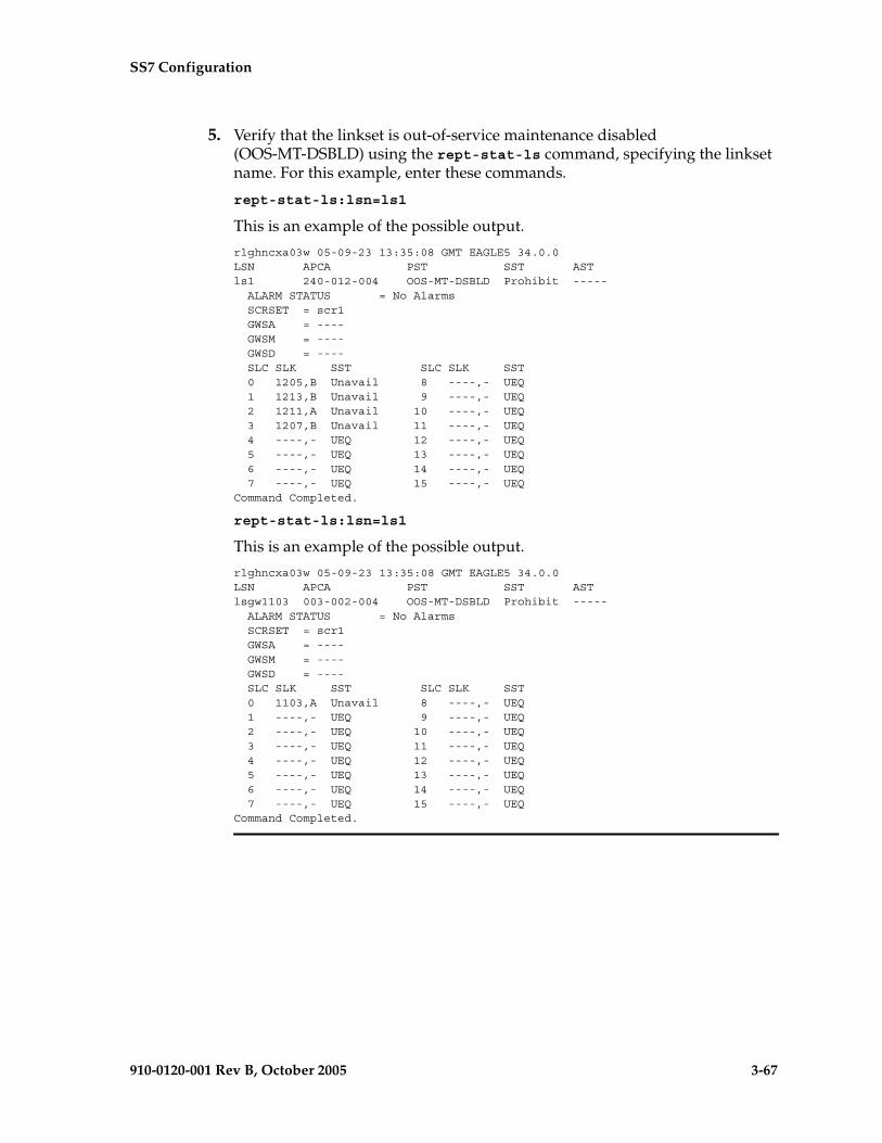
SS7 Configuration
910-0120-001 Rev B, October 2005 3-67
5. Verify that the linkset is out-of-service maintenance disabled (OOS-MT-DSBLD) using the rept-stat-ls command, specifying the linkset name. For this example, enter these commands.
rept-stat-ls:lsn=ls1
This is an example of the possible output.
rlghncxa03w 05-09-23 13:35:08 GMT EAGLE5 34.0.0LSN APCA PST SST ASTls1 240-012-004 OOS-MT-DSBLD Prohibit ----- ALARM STATUS = No Alarms SCRSET = scr1 GWSA = ---- GWSM = ---- GWSD = ---- SLC SLK SST SLC SLK SST 0 1205,B Unavail 8 ----,- UEQ 1 1213,B Unavail 9 ----,- UEQ 2 1211,A Unavail 10 ----,- UEQ 3 1207,B Unavail 11 ----,- UEQ 4 ----,- UEQ 12 ----,- UEQ 5 ----,- UEQ 13 ----,- UEQ 6 ----,- UEQ 14 ----,- UEQ 7 ----,- UEQ 15 ----,- UEQCommand Completed.
rept-stat-ls:lsn=ls1
This is an example of the possible output.
rlghncxa03w 05-09-23 13:35:08 GMT EAGLE5 34.0.0LSN APCA PST SST ASTlsgw1103 003-002-004 OOS-MT-DSBLD Prohibit ----- ALARM STATUS = No Alarms SCRSET = scr1 GWSA = ---- GWSM = ---- GWSD = ---- SLC SLK SST SLC SLK SST 0 1103,A Unavail 8 ----,- UEQ 1 ----,- UEQ 9 ----,- UEQ 2 ----,- UEQ 10 ----,- UEQ 3 ----,- UEQ 11 ----,- UEQ 4 ----,- UEQ 12 ----,- UEQ 5 ----,- UEQ 13 ----,- UEQ 6 ----,- UEQ 14 ----,- UEQ 7 ----,- UEQ 15 ----,- UEQCommand Completed.

3-68 910-0120-001 Rev B, October 2005
SS7 Configuration
6. If any signaling links in the linkset are the last signaling link on a card, the card must be placed out of service before that signaling link can be removed. Verify this by entering the rtrv-slk command and specifying each of the card locations shown in the output of step 2. Do not specify the link parameter. For this example, enter these commands.
rtrv-slk:loc=1205
This is an example of the possible output.
rlghncxa03w 05-09-19 21:17:04 GMT EAGLE5 34.0.0 L2T L1 PCR PCRLOC LINK LSN SLC TYPE SET BPS MODE TSET ECM N1 N21205 B ls1 0 LIMDS0 1 56000 --- --- BASIC --- -----
rtrv-slk:loc=1207
This is an example of the possible output.
rlghncxa03w 05-09-19 21:17:04 GMT EAGLE5 34.0.0 L2T L1 PCR PCRLOC LINK LSN SLC TYPE SET BPS MODE TSET ECM N1 N21207 A ls3 1 LIMV35 1 64000 DCE OFF BASIC --- -----1207 B ls1 3 LIMV35 1 64000 DCE OFF BASIC --- -----
rtrv-slk:loc=1211
This is an example of the possible output.
rlghncxa03w 05-09-19 21:17:04 GMT EAGLE5 34.0.0 L2T L1 PCR PCRLOC LINK LSN SLC TYPE SET BPS MODE TSET ECM N1 N21211 A ls1 2 LIMDS0 1 56000 --- --- BASIC --- -----1211 B ls2 0 LIMDS0 1 56000 --- --- BASIC --- -----
rtrv-slk:loc=1213
This is an example of the possible output.
rlghncxa03w 05-09-19 21:17:04 GMT EAGLE5 34.0.0 L2T L1 PCR PCRLOC LINK LSN SLC TYPE SET BPS MODE TSET ECM N1 N21213 A ls2 1 LIMOCU 1 56000 --- --- BASIC --- -----1213 B ls1 1 LIMOCU 1 56000 --- --- BASIC --- -----
rtrv-slk:loc=1103
This is an example of the possible output.
rlghncxa03w 05-09-19 21:17:04 GMT EAGLE5 34.0.0LOC LINK LSN SLC TYPE1103 A lsn1 0 SS7IPGW
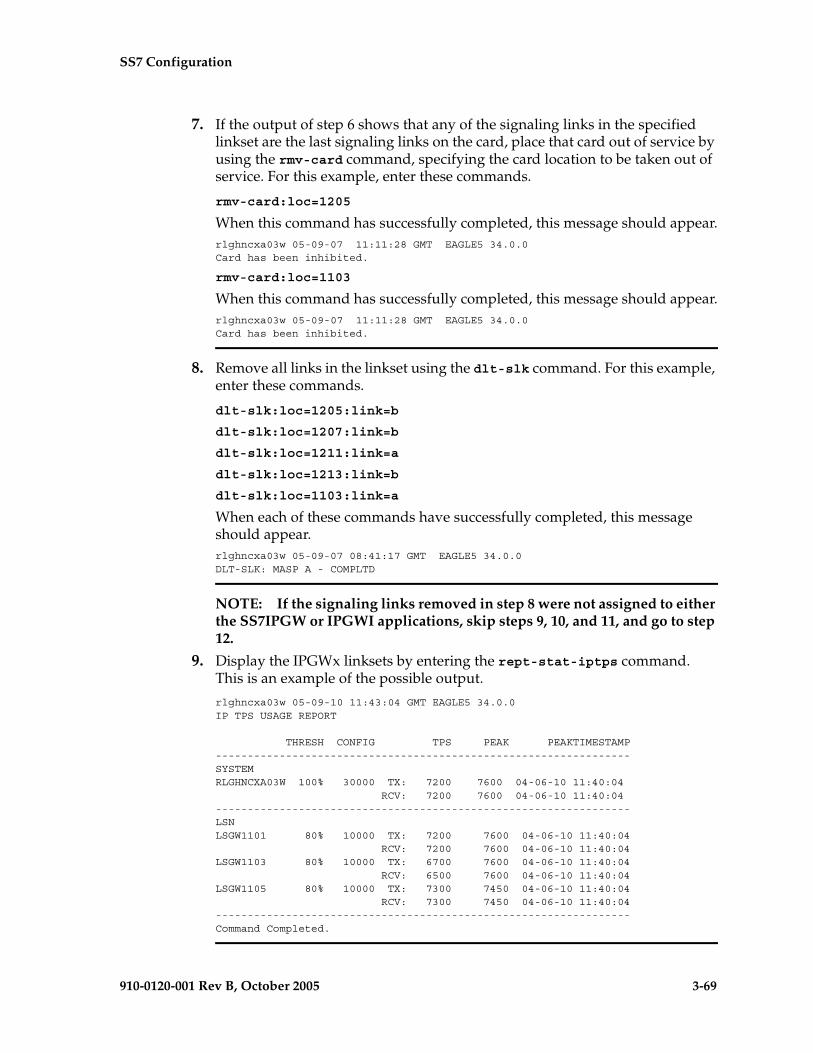
SS7 Configuration
910-0120-001 Rev B, October 2005 3-69
7. If the output of step 6 shows that any of the signaling links in the specified linkset are the last signaling links on the card, place that card out of service by using the rmv-card command, specifying the card location to be taken out of service. For this example, enter these commands.
rmv-card:loc=1205
When this command has successfully completed, this message should appear.rlghncxa03w 05-09-07 11:11:28 GMT EAGLE5 34.0.0Card has been inhibited.
rmv-card:loc=1103
When this command has successfully completed, this message should appear.rlghncxa03w 05-09-07 11:11:28 GMT EAGLE5 34.0.0Card has been inhibited.
8. Remove all links in the linkset using the dlt-slk command. For this example, enter these commands.
dlt-slk:loc=1205:link=b
dlt-slk:loc=1207:link=b
dlt-slk:loc=1211:link=a
dlt-slk:loc=1213:link=b
dlt-slk:loc=1103:link=a
When each of these commands have successfully completed, this message should appear. rlghncxa03w 05-09-07 08:41:17 GMT EAGLE5 34.0.0DLT-SLK: MASP A - COMPLTD
NOTE: If the signaling links removed in step 8 were not assigned to either the SS7IPGW or IPGWI applications, skip steps 9, 10, and 11, and go to step 12.
9. Display the IPGWx linksets by entering the rept-stat-iptps command. This is an example of the possible output.
rlghncxa03w 05-09-10 11:43:04 GMT EAGLE5 34.0.0IP TPS USAGE REPORT
THRESH CONFIG TPS PEAK PEAKTIMESTAMP-----------------------------------------------------------------SYSTEMRLGHNCXA03W 100% 30000 TX: 7200 7600 04-06-10 11:40:04 RCV: 7200 7600 04-06-10 11:40:04-----------------------------------------------------------------LSNLSGW1101 80% 10000 TX: 7200 7600 04-06-10 11:40:04 RCV: 7200 7600 04-06-10 11:40:04LSGW1103 80% 10000 TX: 6700 7600 04-06-10 11:40:04 RCV: 6500 7600 04-06-10 11:40:04LSGW1105 80% 10000 TX: 7300 7450 04-06-10 11:40:04 RCV: 7300 7450 04-06-10 11:40:04-----------------------------------------------------------------Command Completed.

3-70 910-0120-001 Rev B, October 2005
SS7 Configuration
10. Enter the rtrv-ls command with one of the linkset names shown in step 9. This is to verify if the linkset being removed in this procedure is a mate to another IPGWx linkset.
Repeat this step until all the linksets in step 9 have been displayed, or a linkset is found that has the linkset being removed as a mate. For this example, enter this command.
rtrv-ls:lsn=lsgw1105
This is an example of the possible output.
rlghncxa03w 05-09-17 11:43:04 GMT EAGLE5 34.0.0
L3T SLT GWS GWS GWSLSN APCA (SS7) SCRN SET SET BEI LST LNKS ACT MES DIS SLSCI NISlsgw1105 009-002-003 none 1 1 no A 1 off off off no off
CLLI TFATCABMLQ MTPRSE ASL8 ----------- 1 no no
IPGWAPC MATELSN IPTPS LSUSEALM SLKUSEALM yes lsgw1103 10000 70 % 70 %
L2T L1 PCR PCR LOC LINK SLC TYPE SET BPS MODE TSET ECM N1 N2
LP ATM LOC LINK SLC TYPE SET BPS TSEL VCI VPI LL
LP ATM E1ATM LOC LINK SLC TYPE SET BPS TSEL VCI VPI CRC4 SI SN
LOC LINK SLC TYPE IPLIML2
LOC LINK SLC TYPE 1105 A 0 SS7IPGW
L2T PCR PCR E1 E1 LOC LINK SLC TYPE SET BPS ECM N1 N2 LOC PORT TS
L2T PCR PCR T1 T1 LOC LINK SLC TYPE SET BPS ECM N1 N2 LOC PORT TS
Link set table is ( 14 of 1024) 1% full
NOTE: If the rtrv-ls output in step 10 shows that the linkset being removed is not the mate of another IPGWx linkset, skip step 11 and go to step 12.
11. Remove the mate linkset assignment shown in step 10 by performing the “Configuring a Mate IPGWx Linkset” procedure in the Database Administration Manual - IP7 Secure Gateway using these parameters:
:lsn = the name of the linkset shown in the LSN field in step 10
:matelsn = the name of the linkset shown in the MATELSN field in step 10
:action=delete
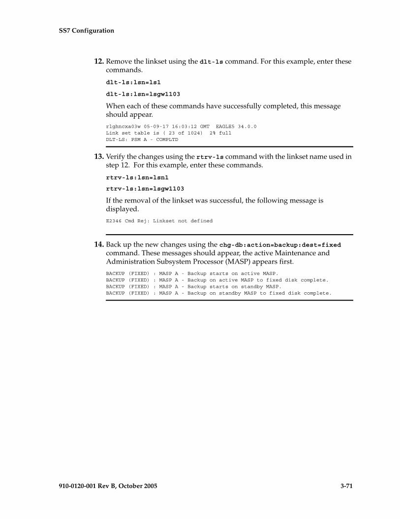
SS7 Configuration
910-0120-001 Rev B, October 2005 3-71
12. Remove the linkset using the dlt-ls command. For this example, enter these commands.
dlt-ls:lsn=ls1
dlt-ls:lsn=lsgw1103
When each of these commands have successfully completed, this message should appear.
rlghncxa03w 05-09-17 16:03:12 GMT EAGLE5 34.0.0Link set table is ( 23 of 1024) 2% fullDLT-LS: PSM A - COMPLTD
13. Verify the changes using the rtrv-ls command with the linkset name used in step 12. For this example, enter these commands.
rtrv-ls:lsn=lsn1
rtrv-ls:lsn=lsgw1103
If the removal of the linkset was successful, the following message is displayed.
E2346 Cmd Rej: Linkset not defined
14. Back up the new changes using the chg-db:action=backup:dest=fixed command. These messages should appear, the active Maintenance and Administration Subsystem Processor (MASP) appears first.
BACKUP (FIXED) : MASP A - Backup starts on active MASP.BACKUP (FIXED) : MASP A - Backup on active MASP to fixed disk complete.BACKUP (FIXED) : MASP A - Backup starts on standby MASP.BACKUP (FIXED) : MASP A - Backup on standby MASP to fixed disk complete.

3-72 910-0120-001 Rev B, October 2005
SS7 Configuration
Flowchart 3-3. Removing a Linkset Containing SS7 Signaling Links (Sheet 1 of 2)
Is thelinkset being
removed assigned toany routes?
Yes
No
Enter thertrv-ls command
ToSheet 2
Enter the rtrv-ls command withthis parameter:
:lsn=<name of the linkset beingremoved>
Enter the dact-slk command with theseparameters:
:loc=<location of the signaling linkassigned to the linkset being removed>
:port=<signaling link port>Repeat this step for all the signaling linksassigned to the linkset being removed.
Perform the the “Removinga Route” procedure in thischapter and remove the
routes
Enter the rmv-card command withthis parameter:
:loc=<location of the cardcontaining the last signaling link on
the card>
Enter the rtrv-rte command withthis parameter:
:lsn=<name of the linkset beingremoved>
Enter the rtrv-slk command with thisparameter:
:loc=<location of the signaling linkassigned to the linkset being removed>
Repeat this step for all the signaling linksassigned to the linkset being removed.
Are any signalinglinks the last signaling
link on the card?
No
Yes
Enter the rept-stat-ls commandwith this parameter:
:lsn=<name of the linkset beingremoved>

SS7 Configuration
910-0120-001 Rev B, October 2005 3-73
Flowchart 3-3. Removing a Linkset Containing SS7 Signaling Links (Sheet 2 of 2)
FromSheet 1
Enter thertrv-ls command with this parameter:
:lsn=<name of the linkset shown in the rept-stat-iptps output>.
This step is being performed to verify if the linksetbeing removed is the mate of another IPGWxlinkset.
Repeat this step for each linkset shown in therept-stat-iptps output until all the linksets have beendisplayed, or until the linkset name being removedis shown in the rtrv-ls output as the mate of anotherlinkset.
Enter the dlt-slk command with theseparameters:
:loc=<location of the signaling linkassigned to the linkset being removed>
:port=<signaling link port>Repeat this step for all the signaling linksassigned to the linkset being removed.
Did the linksetcontain any signaling links
assigned to either theSS7IPGW or IPGWI
applications?
Yes
No
Enter the rept-stat-iptpscommand
Is the linksetbeing removed the mate
of another linkset?
Perform the "Configuring a Mate IPGWx Linkset"procedure in the Database Administration Manual -
IP7 Secure Gateway using these parameters::lsn=<name of the linkset containing the mate linkset>
:matelsn=<name of the linkset being removed>:action=delete
Enter the dlt-ls command withthis parameter:
:lsn=<name of the linkset beingremoved>
Enter the rtrv-ls command with thisparameter:
:lsn=<name of the linkset used inthe dlt-ls output>
Enter thechg-db:action=backup:dest=fixed
command
Yes
No
3-74 910-0120-001 Rev B, October 2005
SS7 Configuration
Changing an SS7 Linkset
This procedure is used to change the definition of linksets that contain SS7 signaling links using the chg-ls command without the gsmscrn, sapci, sapcn, sapcn24, iptps, lsusealm, slkusealm, matelsn, and action parameters of the chg-ls command.
The gsmscrn parameter is used for the GSM MAP Screening feature. To configure an SS7 linkset for the GSM MAP Screening feature, perform the “Configuring a Linkset for the GSM MAP Screening Feature,” in Chapter 5, “GSM MAP Screening Configuration,” in the Database Administration Manual - Features.
The sapci, sapcn, sapcn24, and action parameters are used for configuring secondary adjacent point codes for ITU linksets. For more information on these parameters, see the “Configuring an ITU Linkset with a Secondary Adjacent Point Code (SAPC)” procedure on page 3-113.
The iptps, lsusealm, slkusealm, matelsn, and action parameters are used to configure IPGWx linksets. To configure IPGWx linksets, perform one of these procedures in Chapter 3, “IP7 Secure Gateway Configuration Procedures,” in the Database Administration Manual - IP7 Secure Gateway.
• “Configuring an IPGWx Linkset”
• “Configuring a Mate IPGWx Linkset”
To change X.25 linksets, perform the “Changing an X.25 Linkset” procedure in the Database Administration Manual – Features.
The chg-ls command uses these parameters.
:lsn – The name of the linkset
:nlsn – The new name of the linkset
The linkset name can contain up to 10 characters, with the first character being a letter. However, the SEAS interface supports only eight characters. If this linkset is displayed on the SEAS interface and the linkset name contains more than eight characters, only the first eight characters in the linkset name are shown. If this linkset name contains more than eight characters, and is specified with the linkset commands on the SEAS interface, only the first eight characters can be specified.
:apc/apca/apci/apcn/apcn24 – Adjacent point code – the point code identifying the node that is next to the EAGLE 5 SAS. The adjacent point code can be one of the following types of point codes:
:apc/apca – ANSI point code
:apci – ITU-I point code, ITU-I spare point code
:apcn – 14-bit ITU-N point code, 14-bit ITU-N spare point code
:apcn24 – 24-bit ITU-N point code
SS7 Configuration
910-0120-001 Rev B, October 2005 3-75
NOTE: See “Point Code Formats” on page 2-4 for a definition of the point code types that are used on the EAGLE 5 SAS and for a definition of the different formats that can be used for ITU national point codes. Private point codes can be assigned only to IPGWx linksets. The procedures for configuring IPGWx linksets are in the Database Administration Manual - IP7 Secure Gateway.
:apcntype – Specifies whether or not the linkset containing either a 14-bit ITU-N adjacent point code or a 24-bit ITU-N adjacent point code is being used in China (apcntype=itunchina) or in countries other than China (apcntype=itun). Signaling links in linksets with the apcntype=itunchina parameter are handled according to the specifications in YD/N 068-1997, Technical Specification of National No.7 Signaling System - Message Transfer Part (MTP). Signaling links in linksets with the apcntype=itun parameter are handled according to the specifications in ITU-T Q.2210 (07/96), Switching and Signaling, Broadband ISDN- Signaling Network Protocols. The default value for the apcntype parameter is itun.
Linksets shown in section of the rtrv-ls output with the LSN (CHINA) column (and with either the APCN or APCN24 column) have the acpntype=itunchina parameter assigned to them.
Linksets shown in section of the rtrv-ls output with the LSN column (and with either the APCN or APCN24 column) have the acpntype=itun parameter assigned to them.
:lst – The linkset type of the specified linkset
:clli – The Common Language Location Identifier assigned to this point code. The value of the clli parameter is only displayed in the rtrv-ls command output when a specific linkset is being displayed with the rtrv-ls:lsn=<linkset name> command.
:sltset – The signaling link test message record to be associated with the linkset.
:l3tset – The level 3 timer set table. This parameter identifies which level three timer set is to be assigned to this linkset. Currently, only one is supported.
:scrn – The name of the screenset to be assigned to this linkset if gateway screening is to be used.
:gwsa – Gateway screening action determines whether gateway screening (GWS) is on or off for the specified link set.
:gwsm – Gateway screening messaging is used to turn on or off the display of messages generated for each screened message. When an MSU is rejected by gateway screening, a message is output to alert personnel of the event.
:gwsd – Gateway screening MSU discard is used to turn on or off the discarding of MSUs that bypass the gateway screening function due to load

3-76 910-0120-001 Rev B, October 2005
SS7 Configuration
shedding. Also use this parameter with the redirect function; MSUs that cannot be screened are discarded if you specify gwsd=on.
:bei – The broadcast exception indicator. This parameter indicates whether TFP (transfer prohibited) messages are allowed to be broadcast on the linkset. The yes parameter means TFPs are not broadcast. The no parameter means TFPs are broadcast.
:tfatcabmlq – the TFA/TCA broadcast minimum link quantity shows the minimum number of signaling links in the given link set (or in the combined link set in which it resides) that must be available for traffic. When the number of signaling links in the specified linkset is equal to or greater than the value of the tfatcabmlq parameter, the status of the routes that use the specified linkset is set to allowed and can carry traffic. Otherwise, these routes are restricted. The value of the tfatcabmlq parameter cannot exceed the total number of signaling links contained in the linkset. The system default value for the tfatcabmlq parameter is 0.
The value of the tfatcabmlq parameter is only displayed in the rtrv-ls command output when a specific linkset is being displayed with the rtrv-ls:lsn=<linkset name> command.
The tfatcabmlq parameter exists only in the chg-ls command and not the ent-ls command, because no links are assigned to the linkset when the linkset is first created with the ent-ls command. The default value for the tfatcabmlq parameter (tfatcabmlq=0) is entered for the linkset, and shown in the rtrv-ls output as 1, when a new linkset is added to the database.
When the tfatcabmlq parameter value is 0, the EAGLE 5 SAS broadcasts TFAs/TCAs only when 1/2 of the links in the linkset (or in the combined link set in which it resides) become available. The tfatcabmlq parameter value displayed in the rtrv-ls output is 1/2 of the number of signaling links contained in the linkset, or 1 when the linkset contains 0 to 3 signaling links. As signaling links are added or removed from the linkset, the tfatcabmlq parameter value will be changed automatically.
When the lst=c parameter is specified, or when the current (unchanged) LST value is C, the tfatcabmlq parameter cannot be specified unless the LSRESTRICT SS7 option is on. The state of the LSRESTRICT SS7 option is shown in the rtrv-ss7opts output.
:nis – specifies whether the National Spare for Network Indicator feature is on or off for the specific linkset. This feature allows the linkset to use the national spare value (3) for the network indicator code field in the service information octet (SIO) of the MSU for ANSI linksets and ITU national linksets (linksets containing either 14-bit ITU-N point codes or 24-bit ITU-N point codes). This parameter cannot be specified for ITU international linksets. The default value for the nis parameter is off.For MSUs on incoming linksets, only those MSUs having the network indicator code values shown in Table 3-7 on page 3-77 are allowed into the EAGLE 5 SAS.

SS7 Configuration
910-0120-001 Rev B, October 2005 3-77
For MSUs on outgoing linksets, the network indicator code value in the MSU is changed to either the national network indicator code value (2) or the national spare network indicator code value (3). If the nis parameter is set to off, the network indicator code value is set to 2.
These actions are summarized in Table 3-7 on page 3-77.
The actions described for this parameter apply only if the ITU National and International Spare Point Code Support feature is not enabled.
If the ITU National and International Spare Point Code Support feature is enabled, the nis parameter value is ignored for ITU-I and 14-bit ITU-N linksets. All the network indicator values are permitted on ITU-I and ITU-N linksets, and the network indicator value for transmission is based on the International/National and Spare/Non-Spare status of the DPC of the message.
Having the ITU National and International Spare Point Code Support feature enabled has no effect on ANSI and 24-bit ITU-N linksets. The nis parameter value determines which incoming network indicator spare bit values to permit, and what network indicator spare bit value should be transmitted.
Table 3-7. Actions of the National Spare for Network Indicator Feature
Linkset Type Feature Disabled Feature Enabled
Incoming ANSI Linkset
MSUs containing the national network indicator code (2) are allowed into the EAGLE 5 SAS.
MSUs containing these network indicator code values are allowed into the EAGLE 5 SAS.• National Network Indicator Code
(2)• National Spare Network Indicator
Code (3)
Outgoing ANSI Linkset
The network indicator code value in the MSU is set to the national network indicator code (2).
The network indicator code value in the MSU is set to the national spare network indicator code (3).
Incoming ITU National Linkset
MSUs containing these network indicator code values are allowed into the EAGLE 5 SAS.• International Network
Indicator Code (0)• National Network
Indicator Code (2)
MSUs containing these network indicator code values are allowed into the EAGLE 5 SAS.• International Network Indicator
Code (0)• National Network Indictor Code (2)• National Spare Network Indicator
Code (3)
Outgoing ITU National Linkset
The network indicator code value in the MSU is set to the national network indicator code (2).
The network indicator code value in the MSU is set to the national spare network indicator code (3).

3-78 910-0120-001 Rev B, October 2005
SS7 Configuration
:itutfr – specifies whether or not ITU TFR (transfer restricted) procedures are being used on the linkset. This parameter applies only to linksets with ITU national adjacent point codes (linksets containing either 14-bit ITU-N point codes or 24-bit ITU-N point codes) and can be specified only for linksets with ITU national adjacent point codes. TFR procedures are used to redirect traffic away from a node that is having problems routing traffic to a destination. When a node determines that a destination is restricted, the node sends a TFR message informing the adjacent nodes about the destination’s status. When a destination is restricted, the node should not be used to route messages to the destination even though it still has limited capability to do so. The values for this parameter are either on (ITU TFR procedures are enabled) or off (ITU TFR procedures are disabled).
NOTE: For more information on the itutfr parameter and ITU TFR procedures, see “ITU TFR Procedures” on page 3-33.
:mtprse – shows if the node adjacent to the EAGLE 5 SAS is equipped with the MTP restart capability. The mtprse=yes parameter can only be specified if the MTP restart feature is turned on for ANSI linksets (MTPRS = on in the rtrv-feat command output), or if the ITU MTP restart is on for ITU linksets (ITUMTPRS=on in the rtrv-feat command output). If the MTP restart feature is not turned on, or the APC of the linkset is in the X25 domain, the value of the mtprse parameter defaults to no. The value of the mtprse parameter value is not dependent on the value of the mtprsi parameter (the MTP restart indicator) in the chg-stpopts command. The value of the mtprse parameter is only displayed in the rtrv-ls command output when a specific linkset is being displayed with the rtrv-ls:lsn=<linkset name> command.
NOTE: For more information on the mtprse parameter and MTP restart, see “MTP Restart” on page 3-24.
:slsci – indicates whether the 5-bit to 8-bit SLS conversion feature is used to select signaling links for outgoing messages on the specified link set. If the slsci=yes parameter is specified, the EAGLE 5 SAS replaces any 5-bit SLS values contained in received messages with a random 8-bit value before they are used by the EAGLE 5 SAS to select the outgoing signaling link in that linkset. The 5-bit to 8-bit SLS conversion is also controlled by the slscnv parameter of the chg-stpopts command. The slscnv parameter of the chg-stpopts command has three values: on, off, and perls.
The slsci parameter can only be specified for linksets with ANSI SS7 adjacent point codes.
:asl8 – shows if the node adjacent to the EAGLE 5 SAS is sending MSUs with 8-bit SLSs. If the asl8=yes parameter is specified with the lst=a parameter (a linkset containing access signaling links), this indicates that the originator of the MSUs is generating 8-bit SLSs. For other linkset types, the asl8=yes parameter indicates that the adjacent node is converting 5-bit SLSs to 8-bit SLSs. The SLS in MSUs received by the EAGLE 5 SAS on a linkset that has the asl8=yes parameter assigned to it will not be converted. These MSUs are assumed to contain 8-bit SLSs. If the asl8=no parameter is specified for the

SS7 Configuration
910-0120-001 Rev B, October 2005 3-79
linkset, the SLS will be converted to an 8-bit SLS. The asl8 parameter can only be specified for linksets with ANSI SS7 adjacent point codes. The value of the asl8 parameter is only displayed in the rtrv-ls command output when a specific linkset is being displayed with the rtrv-ls:lsn=<linkset name> command.
NOTE: For more information on the slsci and asl8 parameters and 5-bit to 8-bit conversion, see “5-Bit to 8-Bit SLS Conversion” on page 3-26.
:slsrsb – selects which bit (1 - 4) of the SLS field to use as the least significant bit for signaling link selection in the link set for all ITU messages.
:slsocbit – selects which bit (5 - 16) of the SLS field to use as the most significant bit for signaling link selection in the link set for all ITU messages.
NOTE: For more information on the slsrsb and slsocbit parameters and ITU SLS enhancement, see “ITU SLS Enhancement” on page 3-29.
:multgc – specifies whether multiple group codes are supported for the linkset. When this parameter value is yes, secondary adjacent point codes whose group codes are different from the adjacent point code of the linkset can be assigned to the linkset. If the parameter value is no, the group code of the secondary adjacent point code must be the same as the group code of the linkset’s adjacent point code. For more information on secondary adjacent point codes, go to the “Configuring an ITU Linkset with a Secondary Adjacent Point Code (SAPC)” procedure on page 3-113.
This parameter only applies to linksets whose adjacent point codes are either ITU international point codes or 14-bit ITU national point codes. All the signaling links in this linkset must be assigned to cards running the IPLIMI application. For more information on assigning signaling links to cards running the IPLIMI application, go to the “Adding an IP Signaling Link” procedure in the Database Administration Manual - IP7 Secure Gateway.
The ITU duplicate point code feature must be on before this parameter can be specified. Verify this with the rtrv-feat command. If the ITU duplicate point code feature is turned on, the itupuppc field should be set to on. If the ITU duplicate point code feature is not turned on, enter the chg-feat:itupuppc=on command.
NOTE: Once the ITU duplicate point code feature is turned on with the chg-feat command, it cannot be turned off.
The ITU duplicate point code feature must be purchased before you turn the feature on with the chg-feat command. If you are not sure if you have purchased the ITU duplicate point code feature, contact your Tekelec Sales Representative or Account Representative.
The EAGLE 5 SAS can contain 1024 linksets, with a maximum of 255 of these linksets being gateway linksets. A gateway linkset is a linkset that contains routes to a different network.
The linkset to be changed must exist in the database.

3-80 910-0120-001 Rev B, October 2005
SS7 Configuration
If the adjacent point code (APC) is changed, the new APC must be in the destination point code table and must be defined as a true point code in the destination point code table and cannot be an alias point code. The domain and point code type of the new APC must be the same as the APC being changed. For example, if the current adjacent point code is an ITU-I point code, the new adjacent point code must be an ITU-I point code. The new APC of the linkset cannot match the self ID of the EAGLE 5 SAS. The new APC must be a full point code and cannot be a cluster point code or a network routing point code.
Linksets containing E1 ATM signaling links or IPLIM SAALTALI signaling links cannot contain 24-bit ITU-N APCs or SAPCs. E1 ATM signaling links are identified by the value LIME1ATM in the TYPE column of the rtrv-ls:lsn=<linkset name> output. IPLIM SAALTALI signaling links are identified by the value SAALTALI in the IPLIML2 column of the rtrv-ls:lsn=<linkset name> output.
The signaling link configuration of the linkset can be verified by entering the rtrv-ls:lsn=<linkset name> command specifying the linkset name as shown in step 3.
Use the rtrv-dstn command to verify that the new APC is in the destination point code table and to verify the domain of the new APC. If the new APC is not shown in the rtrv-dstn command output, go to the “Adding a Destination Point Code” procedure on page 2-191 procedures and add the APC to the destination point code table.
To change the APC of a linkset, all signaling links in the linkset must be in the OOS-MT-DSBLD state.
The domain of the linkset’s APC cannot be changed using the chg-ls command. For example, if the current domain of the APC is SS7, the new APC must also be in the SS7 domain. To change the domain of the linkset’s APC, the linkset must be removed from the database using the dlt-ls command and re-entered with the new APC in the different domain using the ent-ls command. To remove the SS7 linkset, go to the “Removing a Linkset Containing SS7 Signaling Links” procedure on page 3-63. To add the SS7 linkset, go to the “Adding an SS7 Linkset” procedure on page 3-17. To add an X.25 linkset, go to the “Adding an X.25 Linkset” procedure in the Database Administration Manual – Features.
The gwsa, gwsm, and gwsd parameters can only be specified if the scrn parameter is defined. Enter the rtrv-ls command to verify that the scrn parameter is defined for the specified linkset. If the scrn parameter is defined, a gateway screening screen set name is shown in the SCRN field of the output. This gateway screening screen set name must also be defined as a gateway screening screen set entity. This can be verified with the rtrv-scrset command.
CAUTION: When Gateway Screening is in the screen test mode, as defined by the linkset parameters gwsa=off and gwsm=on, the gateway screening action in the gateway screening stop action set specified by the actname parameter of the gateway screening screen set at the end of the gateway screening process will be performed.
SS7 Configuration
910-0120-001 Rev B, October 2005 3-81
The chg-ls command has a parameter, gwsd, that can allow the discarding of messages that should have gone through the gateway screening process, but could not. The gwsd parameter is only intended to be used with the database transport access (DTA) feature. If you are not using the DTA feature, the gwsd parameter should not be specified or should be set to no (gwsd=no).
If the gwsa=off parameter is specified, then the gwsd=off parameter must be specified.
To help manage congestion on signaling links, the EAGLE 5 SAS starts the level 3 T31 timer whenever a signaling link goes into congestion level 1 or congestion level 2. The congestion level that is associated with the level 3 T31 timer is set using the chg-stpopts command with the mtpt31ctl parameter and is displayed with the MTPT31CTL field in the rtrv-stpopts command output. When the level 3 timer T31 and the chg-stpopts command are first introduced to the EAGLE 5 SAS, the system default value for the mtpt31ctl parameter of the chg-stpopts command is 1, for congestion level 1, and the system default value for the level 3 T31 timer is 60 seconds. To change the value of the level 3 T31 timer, go to the “Changing Level 3 Timers” procedure on page 3-222. To change value of the mtpt31ctl parameter, enter the either chg-stpopts:mtpt31ctl=1 or the chg-stpopts:mtpt31ctl=2 command, depending on the current value of the mtpt31ctl parameter.
To help prevent the signaling link in the linkset from oscillating in out of service, the EAGLE 5 SAS starts the level 3 T32 timer. When the EAGLE 5 SAS begins restoring an out of service signaling link, the EAGLE 5 SAS starts the level 3 T32 timer. If the signaling link fails to get back into service before the level 3 T32 expires, the EAGLE 5 SAS does not attempt to continue to bring the signaling link into service until the level 3 T32 timer expires. Once the level 3 T32 timer expires, the EAGLE 5 SAS attempts to restore the signaling link into service. When the level 3 timer T32 is first introduced to the EAGLE 5 SAS, the system default value for the level 3 T32 timer is 60 seconds. To change the value of the level 3 T32 timer, go to the “Changing Level 3 Timers” procedure on page 3-222.
The word SEAS cannot be used as a value for the scrn parameter of the chg-ls command. The word SEAS is used in the rtrv-ls command output, in the SCRN field, to show gateway linksets created on the SEAS interface. A gateway linkset combines the functions of a gateway screening screen set and an SS7 linkset specifying the gwsa=on and scrn parameters. Like an EAGLE 5 SAS gateway screening screen set, a gateway linkset defines the screening references that are to be used to screen the messages on the linkset. It also defines the linkset whose messages are to be screened. A gateway linkset can only be configured from a SEAS terminal and not from an EAGLE 5 SAS terminal.
If the clli parameter is specified with the chg-ls command, the value of the clli parameter must match the CLLI value of the adjacent point code of the linkset. The CLLI value of the adjacent point code is shown in the CLLI field of the rtrv-dstn command.
The clli parameter can only be specified with the apc or apca parameters.

3-82 910-0120-001 Rev B, October 2005
SS7 Configuration
If the randsls parameter of the chg-stpopts command is set to either all or class0, a maximum of 16 links continues to be supported in a single linkset to a destination. However, it is now possible to have up to 32 links in a combined linkset to a destination, with a maximum of 16 links per linkset. The 32 links is a change from the current EAGLE 5 SAS maximum of only 16 links per combined linkset, which is due to ITU protocol restrictions. If more than 16 links are used in a combined linkset, the operator needs to be aware that a maximum of 16 links can be used by non-Random SLS traffic over the linkset. The non-Random SLS traffic continues to operate under the rules of the ITU protocol. For more information on the Random SLS Generation feature, go to the “Configuring the System for Random SLS Generation” procedure on page 3-254.
Sample Linkset Configuration
In this procedure, the examples are used to change the definition of linksets ls04 and lsn5. The attributes of linkset ls04 that are changed in this example are the APC, the gateway screening screen set name, to turn on the gateway screening association with linkset ls04. The ITUTFR procedure parameter for linkset lsn5 are changed from off to on. For any optional parameters not specified with the chg-ls command, the values for those parameters are not changed.
Canceling the RTRV-LS and RTRV-DSTN Commands
Because the rtrv-ls and rtrv-dstn commands used in this procedure can output information for a long period of time, the rtrv-ls and rtrv-dstn commands can be canceled and the output to the terminal stopped. There are three ways that the rtrv-ls and rtrv-dstn commands can be canceled.
• Press the F9 function key on the keyboard at the terminal where the rtrv-ls or rtrv-dstn commands were entered.
• Enter the canc-cmd without the trm parameter at the terminal where the rtrv-ls or rtrv-dstn commands were entered.
• Enter the canc-cmd:trm=<xx>, where <xx> is the terminal where the rtrv-ls or rtrv-dstn commands were entered, from another terminal other that the terminal where the rtrv-ls or rtrv-dstn commands were entered. To enter the canc-cmd:trm=<xx> command, the terminal must allow Security Administration commands to be entered from it and the user must be allowed to enter Security Administration commands. The terminal’s permissions can be verified with the rtrv-secu-trm command. The user’s permissions can be verified with the rtrv-user or rtrv-secu-user commands.
For more information about the canc-cmd command, go to the Commands Manual.
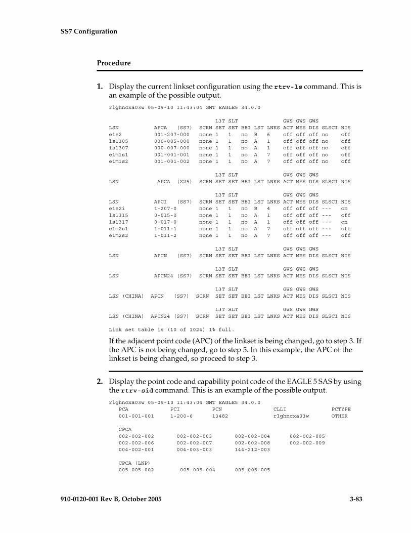
SS7 Configuration
910-0120-001 Rev B, October 2005 3-83
Procedure
1. Display the current linkset configuration using the rtrv-ls command. This is an example of the possible output.
rlghncxa03w 05-09-10 11:43:04 GMT EAGLE5 34.0.0
L3T SLT GWS GWS GWSLSN APCA (SS7) SCRN SET SET BEI LST LNKS ACT MES DIS SLSCI NISe1e2 001-207-000 none 1 1 no B 6 off off off no offls1305 000-005-000 none 1 1 no A 1 off off off no offls1307 000-007-000 none 1 1 no A 1 off off off no offe1m1s1 001-001-001 none 1 1 no A 7 off off off no offe1m1s2 001-001-002 none 1 1 no A 7 off off off no off
L3T SLT GWS GWS GWSLSN APCA (X25) SCRN SET SET BEI LST LNKS ACT MES DIS SLSCI NIS
L3T SLT GWS GWS GWSLSN APCI (SS7) SCRN SET SET BEI LST LNKS ACT MES DIS SLSCI NISe1e2i 1-207-0 none 1 1 no B 4 off off off --- onls1315 0-015-0 none 1 1 no A 1 off off off --- offls1317 0-017-0 none 1 1 no A 1 off off off --- one1m2s1 1-011-1 none 1 1 no A 7 off off off --- offe1m2s2 1-011-2 none 1 1 no A 7 off off off --- off
L3T SLT GWS GWS GWSLSN APCN (SS7) SCRN SET SET BEI LST LNKS ACT MES DIS SLSCI NIS
L3T SLT GWS GWS GWSLSN APCN24 (SS7) SCRN SET SET BEI LST LNKS ACT MES DIS SLSCI NIS
L3T SLT GWS GWS GWSLSN (CHINA) APCN (SS7) SCRN SET SET BEI LST LNKS ACT MES DIS SLSCI NIS
L3T SLT GWS GWS GWSLSN (CHINA) APCN24 (SS7) SCRN SET SET BEI LST LNKS ACT MES DIS SLSCI NIS
Link set table is (10 of 1024) 1% full.
If the adjacent point code (APC) of the linkset is being changed, go to step 3. If the APC is not being changed, go to step 5. In this example, the APC of the linkset is being changed, so proceed to step 3.
2. Display the point code and capability point code of the EAGLE 5 SAS by using the rtrv-sid command. This is an example of the possible output.
rlghncxa03w 05-09-10 11:43:04 GMT EAGLE5 34.0.0 PCA PCI PCN CLLI PCTYPE 001-001-001 1-200-6 13482 rlghncxa03w OTHER
CPCA 002-002-002 002-002-003 002-002-004 002-002-005 002-002-006 002-002-007 002-002-008 002-002-009 004-002-001 004-003-003 144-212-003
CPCA (LNP) 005-005-002 005-005-004 005-005-005
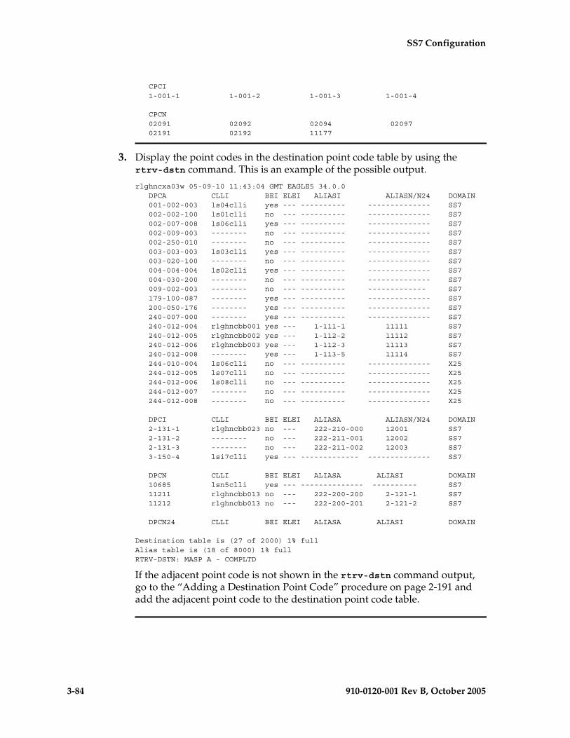
3-84 910-0120-001 Rev B, October 2005
SS7 Configuration
CPCI 1-001-1 1-001-2 1-001-3 1-001-4
CPCN 02091 02092 02094 02097 02191 02192 11177
3. Display the point codes in the destination point code table by using the rtrv-dstn command. This is an example of the possible output.
rlghncxa03w 05-09-10 11:43:04 GMT EAGLE5 34.0.0 DPCA CLLI BEI ELEI ALIASI ALIASN/N24 DOMAIN 001-002-003 ls04clli yes --- ---------- -------------- SS7 002-002-100 ls01clli no --- ---------- -------------- SS7 002-007-008 ls06clli yes --- ---------- -------------- SS7 002-009-003 -------- no --- ---------- -------------- SS7 002-250-010 -------- no --- ---------- -------------- SS7 003-003-003 ls03clli yes --- ---------- -------------- SS7 003-020-100 -------- no --- ---------- -------------- SS7 004-004-004 ls02clli yes --- ---------- -------------- SS7 004-030-200 -------- no --- ---------- -------------- SS7 009-002-003 -------- no --- ---------- ------------- SS7 179-100-087 -------- yes --- ---------- -------------- SS7 200-050-176 -------- yes --- ---------- -------------- SS7 240-007-000 -------- yes --- ---------- -------------- SS7 240-012-004 rlghncbb001 yes --- 1-111-1 11111 SS7 240-012-005 rlghncbb002 yes --- 1-112-2 11112 SS7 240-012-006 rlghncbb003 yes --- 1-112-3 11113 SS7 240-012-008 -------- yes --- 1-113-5 11114 SS7 244-010-004 ls06clli no --- ---------- -------------- X25 244-012-005 ls07clli no --- ---------- -------------- X25 244-012-006 ls08clli no --- ---------- -------------- X25 244-012-007 -------- no --- ---------- -------------- X25 244-012-008 -------- no --- ---------- -------------- X25
DPCI CLLI BEI ELEI ALIASA ALIASN/N24 DOMAIN 2-131-1 rlghncbb023 no --- 222-210-000 12001 SS7 2-131-2 -------- no --- 222-211-001 12002 SS7 2-131-3 -------- no --- 222-211-002 12003 SS7 3-150-4 lsi7clli yes --- ------------- -------------- SS7
DPCN CLLI BEI ELEI ALIASA ALIASI DOMAIN 10685 lsn5clli yes --- -------------- ---------- SS7 11211 rlghncbb013 no --- 222-200-200 2-121-1 SS7 11212 rlghncbb013 no --- 222-200-201 2-121-2 SS7
DPCN24 CLLI BEI ELEI ALIASA ALIASI DOMAIN
Destination table is (27 of 2000) 1% fullAlias table is (18 of 8000) 1% fullRTRV-DSTN: MASP A - COMPLTD
If the adjacent point code is not shown in the rtrv-dstn command output, go to the “Adding a Destination Point Code” procedure on page 2-191 and add the adjacent point code to the destination point code table.

SS7 Configuration
910-0120-001 Rev B, October 2005 3-85
NOTE: If the screen set assigned to the linkset is not being changed, or if the screen set that you wish to assign to the linkset is assigned to other linksets (shown in the SCRN field of the rtrv-ls command output in step 1), skip step 4 and go to step 5.
4. Verify that the gateway screening screen set that is to be assigned to the linkset is in the database by entering the rtrv-scrset command. This is an example of the possible output.rlghncxa03w 05-09-28 16:37:05 GMT EAGLE5 34.0.0ENTIRE GWS DATABASE IS 1% FULLCDPA + AFTPC TABLES ARE 1% FULLTHERE ARE 243 SCREEN SETS AVAILABLE
THE FOLLOWING ARE OVER 80% FULL:SCRN NSFI NSR/ACT FULL RULES TABLES DESTFLD
SCRN NSFI NSR/ACT FULL RULES TABLES DESTFLDfld1 OPC fld2 1% 5 4 NOgws1 OPC gws4 1% 9 7 NOgws2 BLKOPC gws5 1% 5 4 NOls01 SIO ls02 1% 3 3 YESscr1 OPC opc1 1% 37 10 YESscr2 OPC opc2 2% 75 22 YESscr3 OPC opc3 2% 75 22 YESscr4 OPC opc1 51% 2075 22 NOscr5 OPC opc1 51% 2075 22 YESscr6 OPC opc1 51% 2075 22 NOss28 OPC opc1 51% 2075 22 YESwrd1 SIO iec 1% 6 5 YES
If you wish to examine the contents of a particular screen set, enter the rtrv-scrset:scrn=<screen set name> command specifying a screen set name shown in the SCRN field of either the rtrv-scrset command executed in this step or the rtrv-ls command executed in step 1. for this example, enter the rtrv-scrset:scrn=scr1 command This is an example of the possible output.rtrv-scrset:scrn=scr1
rlghncxa03w 05-09-14 16:39:04 GMT EAGLE5 34.0.0SCRN NSFI NSR/ACT RULES DESTFLDscr1 OPC opc1 3 Y BLKDPC bkd2 2 CGPA cgp1 3 TT tt1 3 TT tt2 3 TT tt3 4 CDPA cdp1 3 CDPA cdp2 3 CDPA cdp3 4 AFTPC end1 9
The output of this command shows the screens that make up the screen set. These screens can be examined by entering the gateway screening retrieve command corresponding the to the value in the NSFI field and specifying the screening reference name shown in the NSR/ACT field. For this example, you enter these commands to examine the screens in the screen set.

3-86 910-0120-001 Rev B, October 2005
SS7 Configuration
rtrv-scr-opc:sr=opc1
rtrv-scr-blkdpc:sr=bkd2
rtrv-scr-cgpa:sr=cgp1
rtrv-scr-tt:sr=tt1
rtrv-scr-tt:sr=tt2
rtrv-scr-tt:sr=tt3
rtrv-scr-cdpa:sr=cdp1
rtrv-scr-cdpa:sr=cdp2
rtrv-scr-cdpa:sr=cdp3
rtrv-scr-aftpc:sr=end1
If the screen set that you wish to assign to the linkset is not in the database, go to the “Adding a Screen Set” procedure in the Database Administration Manual - Gateway Screening and add the screen set to the database.
5. Display the current linkset configuration of the linkset to be changed using the rtrv-ls command with the linkset name. For this example, enter these commands.
rtrv-ls:lsn=ls04
This is an example of the possible output.rlghncxa03w 05-09-17 11:43:04 GMT EAGLE5 34.0.0
L3T SLT GWS GWS GWSLSN APCA (SS7) SCRN SET SET BEI LST LNKS ACT MES DIS SLSCI NISls04 001-002-003 scr2 1 1 no a 4 off off off yes off
CLLI TFATCABMLQ MTPRSE ASL8 IPGWAPC ls04clli 2 no no no
L2T L1 PCR PCR LOC LINK SLC TYPE SET BPS MODE TSET ECM N1 N2 1205 b 0 LIMDS0 1 56000 --- --- BASIC --- ----- 1213 b 1 LIMOCU 1 56000 --- --- BASIC --- ----- 1211 a 2 LIMDS0 1 56000 --- --- BASIC --- ----- 1207 b 3 LIMV35 1 64000 DCE OFF BASIC --- -----
LP ATM LOC LINK SLC TYPE SET BPS TSEL VCI VPI LL
LP ATM E1ATM LOC LINK SLC TYPE SET BPS TSEL VCI VPI CRC4 SI SN
LOC LINK SLC TYPE IPLIML2
LOC LINK SLC TYPE
L2T PCR PCR E1 E1 LOC LINK SLC TYPE SET BPS ECM N1 N2 LOC PORT TS
L2T PCR PCR T1 T1 LOC LINK SLC TYPE SET BPS ECM N1 N2 LOC PORT TS
Link set table is ( 24 of 1024) 2% full

SS7 Configuration
910-0120-001 Rev B, October 2005 3-87
rtrv-ls:lsn=lsn5
This is an example of the possible output.
rlghncxa03w 05-09-17 11:43:04 GMT EAGLE5 34.0.0
L3T SLT GWS GWS GWSLSN APCN (SS7) SCRN SET SET BEI LST LNKS ACT MES DIS SLSCI NISlsn5 10685 scr3 1 1 no a 3 on off off --- on
CLLI TFATCABMLQ MTPRSE ASL8 SLSOCBIT SLSRSB ITUTFR lsn5clli 1 no no none 1 off
GSMSCRN off
L2T L1 PCR PCR LOC LINK SLC TYPE SET BPS MODE TSET ECM N1 N2 2105 b 0 LIMDS0 1 56000 --- --- BASIC --- ----- 2113 b 1 LIMOCU 1 56000 --- --- BASIC --- ----- 2111 a 2 LIMDS0 1 56000 --- --- BASIC --- -----
LP ATM LOC LINK SLC TYPE SET BPS TSEL VCI VPI LL
LP ATM E1ATM LOC LINK SLC TYPE SET BPS TSEL VCI VPI CRC4 SI SN
LOC LINK SLC TYPE IPLIML2
LOC LINK SLC TYPE
L2T PCR PCR E1 E1 LOC LINK SLC TYPE SET BPS ECM N1 N2 LOC PORT TS
L2T PCR PCR T1 T1 LOC LINK SLC TYPE SET BPS ECM N1 N2 LOC PORT TS
Link set table is ( 24 of 1024) 2% full
NOTE: If the mtprse=yes parameter is not being specified for the linkset, skip steps 6 through 11, and go to step 12.
6. If you wish to use either the ANSI MTP restart feature or the ITU MTP restart feature, enter the rtrv-feat command to verify that either of these features are on. The entry MTPRS = on in the rtrv-feat command output shows that the ANSI MTP restart feature is on. The entry ITUMTPRS = on in the rtrv-feat command output shows that the ITU MTP restart feature is on. In this example, both features are off.
NOTE: The rtrv-feat command output contains other fields that are not used by this procedure. If you wish to see all the fields displayed by the rtrv-feat command, see the rtrv-feat command description in the Commands Manual.
If both the ANSI and ITU MTP restart feature are on, skip steps 7 and 8 and go to step 9.

3-88 910-0120-001 Rev B, October 2005
SS7 Configuration
NOTE: If you are not going to turn the ANSI MTP restart feature on, or if the output of the rtrv-feat command in step 6 shows that the ANSI MTP restart feature is on (shown by the MPTRS = on entry), skip this step and go to step 8.
7. Turn the ANSI MTP restart feature on by entering this command.
chg-feat:mtprs=on
NOTE: Once the ANSI MTP restart feature is turned on with the chg-feat command, it cannot be turned off.
The ANSI MTP restart feature must be purchased before you turn the feature on with the chg-feat command. If you are not sure if you have purchased the ANSI MTP restart feature, contact your Tekelec Sales Representative or Account Representative.
When this command has successfully completed, this message should appear.
rlghncxa03w 05-09-10 11:43:04 GMT EAGLE5 34.0.0CHG-FEAT: MASP A - COMPLTD
NOTE: If you are not going to turn the ITU MTP restart feature on, or if the output of the rtrv-feat command in step 6 shows that the ITU MTP restart feature is on (shown by the ITUMPTRS = on entry), skip this step and go to step 9.
8. Turn the ITU MTP restart feature on by entering this command.
chg-feat:itumtprs=on
NOTE: Once the ITU MTP restart feature is turned on with the chg-feat command, it cannot be turned off.
The ITU MTP restart feature must be purchased before you turn the feature on with the chg-feat command. If you are not sure if you have purchased the ITU MTP restart feature, contact your Tekelec Sales Representative or Account Representative.
When this command has successfully completed, this message should appear.
rlghncxa03w 05-09-10 11:43:04 GMT EAGLE5 34.0.0CHG-FEAT: MASP A - COMPLTD
SS7 Configuration
910-0120-001 Rev B, October 2005 3-89
9. Enter the rtrv-stpopts command to display the value of the mtprsi and mtprsit parameters of the chg-stpopts command.
The mptrsi parameter either enables (mtprsi=yes) or disables (mtprsi=no) the MTP restart process on the EAGLE 5 SAS.
The mtprsit parameter (the MTP restart isolation timer) specifies the minimum amount of time that the EAGLE 5 SAS is isolated before the MTP restart process is started. The value of the mtprsit parameter is from 2 to 900 seconds, with a system default value of 5 seconds.
The value of the mtprsi parameter is shown in the MTPRSI field of the rtrv-stpopts command output. The value of the mtprsit parameter is shown in the MTPRSIT field of the rtrv-stpopts command output, and is shown in milliseconds.
This is an example of the possible output.rlghncxa03w 05-09-17 16:02:05 GMT EAGLE5 34.0.0STP OPTIONS-----------------------MTPRSI noMTPRSIT 5000
NOTE: The rtrv-stpopts command output contains other fields that are not used by this procedure. If you wish to see all the fields displayed by the rtrv-stpopts command, see the rtrv-stpopts command description in the Commands Manual.
To change the value of the MTPRSI or the MTPRSIT fields, go to step 10. Otherwise, skip steps 10 and 11, and go to step 12.
10. Enable the MTP restart process on the EAGLE 5 SAS by changing the value of the MTPRSI field of the rtrv-stpopts command output. Enter the chg-stpopts command with the mtprsi parameter.
chg-stpopts:mtprsi=yes
If you wish to change the value of the MTP restart isolation timer, enter chg-stpopts command with the mtprsit parameter.
chg-stpopts:mtprsit=7500
If you wish to change the value of the MTP restart isolation timer and enable the MTP restart process, enter chg-stpopts command with both the mtprsi=yes and mtprsit parameters.
chg-stpopts:mtprsi=yes:mtprsit=7500
For this example, the MTP restart process is enabled and the value of the MTP restart isolation timer is changed.
When the chg-stpopts command has successfully completed, this message should appear.
rlghncxa03w 05-09-07 00:22:57 GMT EAGLE5 34.0.0CHG-STPOPTS: MASP A - COMPLTD

3-90 910-0120-001 Rev B, October 2005
SS7 Configuration
11. Verify the changes using the rtrv-stpopts command. This is an example of the possible output.
rlghncxa03w 05-09-17 16:02:05 GMT EAGLE5 34.0.0STP OPTIONS-----------------------MTPRSI yesMTPRSIT 7500
NOTE: The rtrv-stpopts command output contains other fields that are not used by this procedure. If you wish to see all the fields displayed by the rtrv-stpopts command, see the rtrv-stpopts command description in the Commands Manual.
NOTE: If the slsci or asl8 parameters are not being specified for the linkset, skip steps 12 through 14, and go to step 15. The slsci and asl8 parameters can be specified only for linksets with ANSI APCs.NOTE: If the rtrv-stpopts command was performed in steps 9 and 11, skip this step and go to step 13.
12. Display the existing value for the slscnv parameter by entering the rtrv-stpopts command. The value for the slscnv parameter is shown in the SLSCNV field. This is an example of the possible output.
rlghncxa03w 05-09-17 16:02:05 GMT EAGLE5 34.0.0STP OPTIONS-----------------------SLSCNV on
NOTE: The rtrv-stpopts command output contains other fields that are not used by this procedure. If you wish to see all the fields displayed by the rtrv-stpopts command, see the rtrv-stpopts command description in the Commands Manual.
13. Change the slscnv parameter. For this example, the value of the slscnv parameter is being changed from on to perls. Enter this command.
chg-stpopts:slscnv=perls
When this command has successfully completed, this message should appear.rlghncxa03w 05-09-07 00:22:57 GMT EAGLE5 34.0.0CHG-STPOPTS: MASP A - COMPLTD
14. Verify the changes using the rtrv-stpopts command. This is an example of the possible output.
rlghncxa03w 05-09-17 16:02:05 GMT EAGLE5 34.0.0STP OPTIONS-----------------------SLSCNV perls
NOTE: The rtrv-stpopts command output contains other fields that are not used by this procedure. If you wish to see all the fields displayed by the rtrv-stpopts command, see the rtrv-stpopts command description in the Commands Manual.
SS7 Configuration
910-0120-001 Rev B, October 2005 3-91
NOTE: If the slsocbit parameter is not being specified for the linkset, skip steps 15 and 16, and go to step 17. The slsocbit parameter can be specified only for linksets with either ITU-I or ITU-N APCs (either 14-bit or 24-bit ITU-N APCs).
NOTE: If the rtrv-feat command was performed in step 6, skip this step and go to step 16.
15. To use the slsocbit parameter with either the chg-ls command, the Use of the Other CIC Bit feature must be on. Enter the rtrv-feat command to verify that either of this feature is on. The entry SLSOCB = on in the rtrv-feat command output shows that this feature is on. In this example, the Use of the Other CIC Bit feature is off.
NOTE: The rtrv-feat command output contains other fields that are not used by this procedure. If you wish to see all the fields displayed by the rtrv-feat command, see the rtrv-feat command description in the Commands Manual.7
NOTE: If the Use of the Other CIC Bit feature is on (SLSOCB = on), skip this step and go to step 17.
16. Turn the Use of the Other CIC Bit feature is on feature on by entering this command.
chg-feat:slsocb=on
NOTE: Once the Use of the Other CIC Bit feature is turned on with the chg-feat command, it cannot be turned off.
The Use of the Other CIC Bit feature must be purchased before you turn the feature on with the chg-feat command. If you are not sure if you have purchased the Use of the Other CIC Bit feature, contact your Tekelec Sales Representative or Account Representative.
When this command has successfully completed, this message should appear.
rlghncxa03w 05-09-10 11:43:04 GMT EAGLE5 34.0.0CHG-FEAT: MASP A - COMPLTD
3-92 910-0120-001 Rev B, October 2005
SS7 Configuration
NOTE: If the multgc parameter is not being specified for the linkset, skip steps 17, 18, 19, and 20, and go to step 21. If the multgc parameter value is being changed to no, skip steps 17, and 18, and go to step 19. The multgc parameter can be specified only for linksets with either ITU-I or 14-bit ITU-N APCs, and linksets that contain signaling links running the IPLIMI application.
NOTE: If the rtrv-feat command was performed in steps 6 or 15, skip this step and go to step 18.
17. To specify the multgc=yes parameter with the chg-ls command, the ITU Duplicate Point Code feature must be on. For the ITU Duplicate Point Code feature to be on, the Multiple Point Code feature must be on. Enter the rtrv-feat command to verify that either of these features are on. The entry MPC = on in the rtrv-feat command output shows that the Multiple Point Code feature is on. The entry ITUDUPPC = on in the rtrv-feat command output shows that the ITU Duplicate Point Code feature is on. In this example, both features are off.
NOTE: The rtrv-feat command output contains other fields that are not used by this procedure. If you wish to see all the fields displayed by the rtrv-feat command, see the rtrv-feat command description in the Commands Manual.7
NOTE: If the ITU Duplicate Point Code feature is on (ITUDUPPC = on), skip this step and go to step 19.
18. Turn the ITU Duplicate Point Code feature on, and the Multiple Point Code feature if necessary, by entering one of these commands.
To turn the ITU Duplicate Point Code feature on only.
chg-feat:ituduppc=on
To turn both the ITU Duplicate Point Code and Multiple Point Code features on.
chg-feat:mpc=on:ituduppc=on
NOTE: Once the ITU Duplicate Point Code and Multiple Point Code features are turned on with the chg-feat command, they cannot be turned off.
The ITU Duplicate Point Code and Multiple Point Code features must be purchased before you turn either of these features on with the chg-feat command. If you are not sure if you have purchased these features, contact your Tekelec Sales Representative or Account Representative.
When this command has successfully completed, this message should appear.
rlghncxa03w 05-09-10 11:43:04 GMT EAGLE5 34.0.0CHG-FEAT: MASP A - COMPLTD

SS7 Configuration
910-0120-001 Rev B, October 2005 3-93
NOTE: If the multgc parameter value is not being changed, or is being changed to yes, skip steps 19 and 20, and go to step 21.
19. If the multgc parameter value is changed to no, the linkset can contain only one secondary adjacent point code. An ITU international linkset can contain only one 14-bit ITU national secondary adjacent point code. If the ITU international linkset contains more than one 14-bit ITU national secondary adjacent point code, all but one of these 14-bit ITU national secondary adjacent point codes must be removed from the linkset. An ITU national linkset can contain only one ITU international secondary adjacent point code. All 14-bit ITU-N secondary adjacent point codes must be removed from the linkset. All routes to these secondary adjacent point codes must be removed from the database before the secondary adjacent point codes can be removed.
Display the routes using the secondary adjacent point code being removed from the linkset with the rtrv-rte command, specifying the secondary adjacent point code being removed as the value of the dpc parameter.
For this example, enter these commands.
rtrv-rte:dpcn=11213-de
This is an example of the possible output.
rlghncxa03w 05-09-07 11:43:04 GMT EAGLE5 34.0.0
DPCN ALIASA ALIASI LSN RC APC11213-de --------------- ---------- lsn3 10 11213-de CLLI=-----------
rtrv-rte:dpcn=12114-fr
This is an example of the possible output.
rlghncxa03w 05-09-07 11:43:04 GMT EAGLE5 34.0.0
DPCN ALIASA ALIASI LSN RC APC12114-fr --------------- ---------- lsn3 10 12114-fr CLLI=-----------
rtrv-rte:dpcn=12115-uk
This is an example of the possible output.
rlghncxa03w 05-09-07 11:43:04 GMT EAGLE5 34.0.0
DPCN ALIASA ALIASI LSN RC APC12115-uk --------------- ---------- lsn3 10 12115-uk CLLI=-----------
If the secondary adjacent point code is assigned to a route, that route must be removed from the database. Go to the “Removing a Route” procedure on page 3-189 to remove the route from the database.
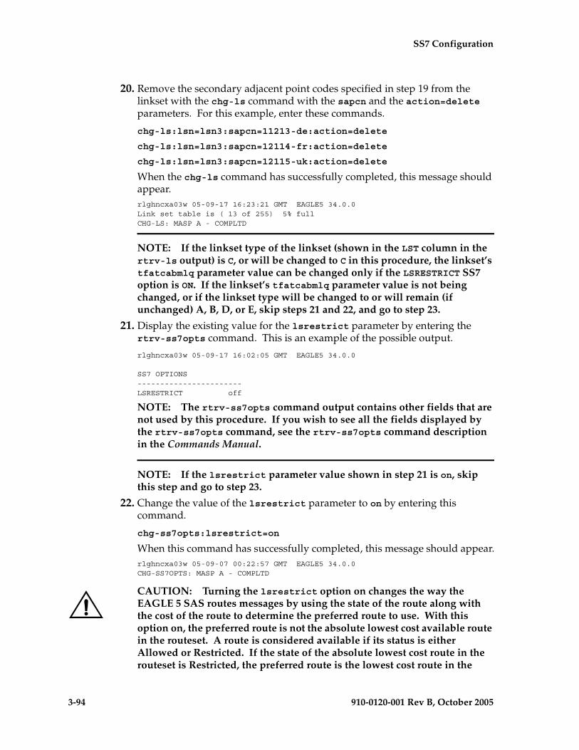
3-94 910-0120-001 Rev B, October 2005
SS7 Configuration
20. Remove the secondary adjacent point codes specified in step 19 from the linkset with the chg-ls command with the sapcn and the action=delete parameters. For this example, enter these commands.
chg-ls:lsn=lsn3:sapcn=11213-de:action=delete
chg-ls:lsn=lsn3:sapcn=12114-fr:action=delete
chg-ls:lsn=lsn3:sapcn=12115-uk:action=delete
When the chg-ls command has successfully completed, this message should appear.rlghncxa03w 05-09-17 16:23:21 GMT EAGLE5 34.0.0Link set table is ( 13 of 255) 5% fullCHG-LS: MASP A - COMPLTD
NOTE: If the linkset type of the linkset (shown in the LST column in the rtrv-ls output) is C, or will be changed to C in this procedure, the linkset’s tfatcabmlq parameter value can be changed only if the LSRESTRICT SS7 option is ON. If the linkset’s tfatcabmlq parameter value is not being changed, or if the linkset type will be changed to or will remain (if unchanged) A, B, D, or E, skip steps 21 and 22, and go to step 23.
21. Display the existing value for the lsrestrict parameter by entering the rtrv-ss7opts command. This is an example of the possible output.
rlghncxa03w 05-09-17 16:02:05 GMT EAGLE5 34.0.0
SS7 OPTIONS-----------------------LSRESTRICT off
NOTE: The rtrv-ss7opts command output contains other fields that are not used by this procedure. If you wish to see all the fields displayed by the rtrv-ss7opts command, see the rtrv-ss7opts command description in the Commands Manual.
NOTE: If the lsrestrict parameter value shown in step 21 is on, skip this step and go to step 23.
22. Change the value of the lsrestrict parameter to on by entering this command.
chg-ss7opts:lsrestrict=on
When this command has successfully completed, this message should appear.rlghncxa03w 05-09-07 00:22:57 GMT EAGLE5 34.0.0CHG-SS7OPTS: MASP A - COMPLTD
CAUTION: Turning the lsrestrict option on changes the way the EAGLE 5 SAS routes messages by using the state of the route along with the cost of the route to determine the preferred route to use. With this option on, the preferred route is not the absolute lowest cost available route in the routeset. A route is considered available if its status is either Allowed or Restricted. If the state of the absolute lowest cost route in the routeset is Restricted, the preferred route is the lowest cost route in the
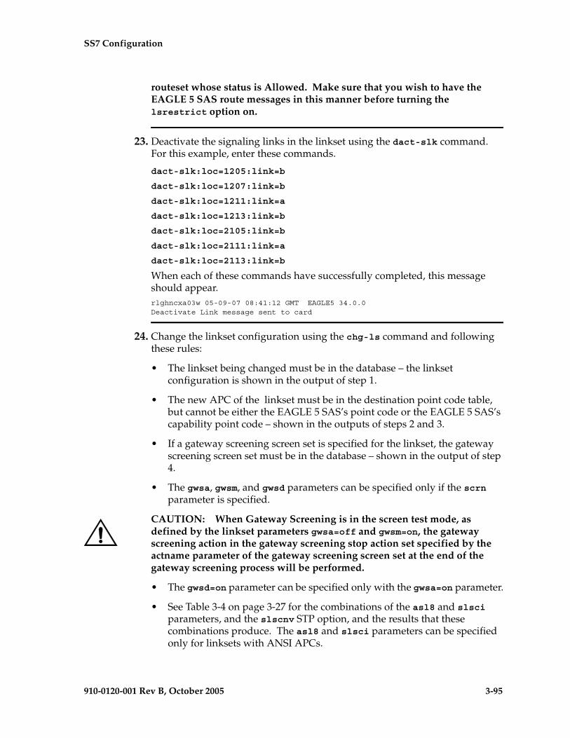
SS7 Configuration
910-0120-001 Rev B, October 2005 3-95
routeset whose status is Allowed. Make sure that you wish to have the EAGLE 5 SAS route messages in this manner before turning the lsrestrict option on.
23. Deactivate the signaling links in the linkset using the dact-slk command. For this example, enter these commands.
dact-slk:loc=1205:link=b
dact-slk:loc=1207:link=b
dact-slk:loc=1211:link=a
dact-slk:loc=1213:link=b
dact-slk:loc=2105:link=b
dact-slk:loc=2111:link=a
dact-slk:loc=2113:link=b
When each of these commands have successfully completed, this message should appear.rlghncxa03w 05-09-07 08:41:12 GMT EAGLE5 34.0.0Deactivate Link message sent to card
24. Change the linkset configuration using the chg-ls command and following these rules:
• The linkset being changed must be in the database – the linkset configuration is shown in the output of step 1.
• The new APC of the linkset must be in the destination point code table, but cannot be either the EAGLE 5 SAS’s point code or the EAGLE 5 SAS’s capability point code – shown in the outputs of steps 2 and 3.
• If a gateway screening screen set is specified for the linkset, the gateway screening screen set must be in the database – shown in the output of step 4.
• The gwsa, gwsm, and gwsd parameters can be specified only if the scrn parameter is specified.
CAUTION: When Gateway Screening is in the screen test mode, as defined by the linkset parameters gwsa=off and gwsm=on, the gateway screening action in the gateway screening stop action set specified by the actname parameter of the gateway screening screen set at the end of the gateway screening process will be performed.
• The gwsd=on parameter can be specified only with the gwsa=on parameter.
• See Table 3-4 on page 3-27 for the combinations of the asl8 and slsci parameters, and the slscnv STP option, and the results that these combinations produce. The asl8 and slsci parameters can be specified only for linksets with ANSI APCs.

3-96 910-0120-001 Rev B, October 2005
SS7 Configuration
• The nis=on parameter cannot be specified for linksets with ITU-I adjacent point codes.
• The mtprse=yes parameter cannot be specified if the linkset contain signaling links with the ipliml2 parameter assigned.
• The multgc=yes parameter can be specified only for linksets with either ITU-I or 14-bit ITU-N APCs, and linksets that contain signaling links running the IPLIMI application.
• The itutfr=on parameter can be specified only for linksets with ITU-N APCs (either 14-bit or 24-bit ITU-N APCs).
• If the lst=c parameter is specified, or if the current (unchanged) LST value is C, the tfatcabmlq parameter cannot be specified unless the LSRESTRICT SS7 option is on.
• The value of the tfatcabmlq parameter cannot exceed the number of signaling links assigned to the linkset.
• The apcntype parameter can be used only with 14-bit ITU-N or 24-bit ITU-N adjacent point codes.
For this example, enter these commands.
chg-ls:lsn=ls04:apca=240-070-000:scrn=scr7:gwsa=on:nis=on
chg-ls:lsn=lsn5:apca=10685:itutfr=on
When each of these commands has successfully completed, this message should appear.
rlghncxa03w 05-09-07 08:38:45 GMT EAGLE5 34.0.0Link set table is ( 24 of 1024) 2% fullCHG-LS: MASP A - COMPLTD
25. Verify the changes using the rtrv-ls command, specifying the linkset name that was changed in step 24. For this example, enter this command.
rtrv-ls:lsn=ls04
This is an example of the possible output.
rlghncxa03w 05-09-17 11:43:04 GMT EAGLE5 34.0.0
L3T SLT GWS GWS GWSLSN APCA (SS7) SCRN SET SET BEI LST LNKS ACT MES DIS SLSCI NISls04 240-070-000 scr7 1 1 no a 4 on off off yes on
CLLI TFATCABMLQ MTPRSE ASL8 IPGWAPC ls04clli 2 no no no
L2T L1 PCR PCR LOC LINK SLC TYPE SET BPS MODE TSET ECM N1 N2 1205 b 0 LIMDS0 1 56000 --- --- BASIC --- ----- 1213 b 1 LIMOCU 1 56000 --- --- BASIC --- ----- 1211 a 2 LIMDS0 1 56000 --- --- BASIC --- ----- 1207 b 3 LIMV35 1 64000 DCE OFF BASIC --- -----

SS7 Configuration
910-0120-001 Rev B, October 2005 3-97
LP ATM LOC LINK SLC TYPE SET BPS TSEL VCI VPI LL
LP ATM E1ATM LOC LINK SLC TYPE SET BPS TSEL VCI VPI CRC4 SI SN
LOC LINK SLC TYPE IPLIML2
LOC LINK SLC TYPE
L2T PCR PCR E1 E1 LOC LINK SLC TYPE SET BPS ECM N1 N2 LOC PORT TS
L2T PCR PCR T1 T1 LOC LINK SLC TYPE SET BPS ECM N1 N2 LOC PORT TS
Link set table is ( 24 of 1024) 2% full
rtrv-ls:lsn=lsn5
This is an example of the possible output.rlghncxa03w 05-09-17 11:43:04 GMT EAGLE5 34.0.0
L3T SLT GWS GWS GWSLSN APCN (SS7) SCRN SET SET BEI LST LNKS ACT MES DIS SLSCI NISlsn5 10685 scr3 1 1 no a 3 on off off --- on
CLLI TFATCABMLQ MTPRSE ASL8 SLSOCBIT SLSRSB ITUTFR lsn5clli 1 no no none 1 on
GSMSCRN off
L2T L1 PCR PCR LOC LINK SLC TYPE SET BPS MODE TSET ECM N1 N2 2105 b 0 LIMDS0 1 56000 --- --- BASIC --- ----- 2113 b 1 LIMOCU 1 56000 --- --- BASIC --- ----- 2111 a 2 LIMDS0 1 56000 --- --- BASIC --- -----
LP ATM LOC LINK SLC TYPE SET BPS TSEL VCI VPI LL
LP ATM E1ATM LOC LINK SLC TYPE SET BPS TSEL VCI VPI CRC4 SI SN
LOC LINK SLC TYPE IPLIML2
LOC LINK SLC TYPE
L2T PCR PCR E1 E1 LOC LINK SLC TYPE SET BPS ECM N1 N2 LOC PORT TS
L2T PCR PCR T1 T1 LOC LINK SLC TYPE SET BPS ECM N1 N2 LOC PORT TS
Link set table is ( 24 of 1024) 2% full
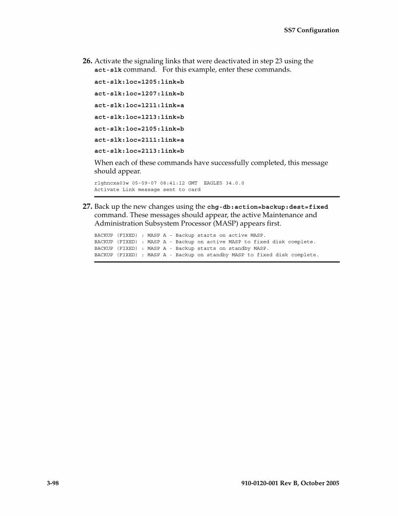
3-98 910-0120-001 Rev B, October 2005
SS7 Configuration
26. Activate the signaling links that were deactivated in step 23 using the act-slk command. For this example, enter these commands.
act-slk:loc=1205:link=b
act-slk:loc=1207:link=b
act-slk:loc=1211:link=a
act-slk:loc=1213:link=b
act-slk:loc=2105:link=b
act-slk:loc=2111:link=a
act-slk:loc=2113:link=b
When each of these commands have successfully completed, this message should appear.
rlghncxa03w 05-09-07 08:41:12 GMT EAGLE5 34.0.0Activate Link message sent to card
27. Back up the new changes using the chg-db:action=backup:dest=fixed command. These messages should appear, the active Maintenance and Administration Subsystem Processor (MASP) appears first.
BACKUP (FIXED) : MASP A - Backup starts on active MASP.BACKUP (FIXED) : MASP A - Backup on active MASP to fixed disk complete.BACKUP (FIXED) : MASP A - Backup starts on standby MASP.BACKUP (FIXED) : MASP A - Backup on standby MASP to fixed disk complete.

SS7 Configuration
910-0120-001 Rev B, October 2005 3-99
Flowchart 3-4. Changing an SS7 Linkset (Sheet 1 of 14)
NOTE: Note: This procedure can require that these features are enabled: ANSI MTP Restart, ITU MTP Restart, ITU National Duplicate Point Code, Multiple Point Code, and ITU SLS Enhancement. Before executing this procedure, make sure you have purchased the features you plan to enable. If you are not sure if you have purchased these features, contact your Tekelec Sales Representative or Account Representative.
Will the APCof the linkset be changed?
(See Note)
No
Yes
Enter the rtrv-lscommand
Is the APC inthe DPC table?
Yes
No
Enter the rtrv-dstncommand
To Sheet3
Go to the "Adding aDestination Point Code"procedure and add theAPC to the DPC table
Enter the rtrv-sidcommand
Is the scrnparameter to bespecified for the
linkset?
Yes
No
Enter the rtrv-ls:lsn=<axxxxxxx>command where <axxxxxxx> isthe linkset name being changed
To Sheet2
Note: If the adjacent point code is beingchanged, the point code type of the newadjacent point code must be the same
as the current adjacent point code.
For example, if the current adjacentpoint code is an ITU-I point code, thenew adjacent point code must be an
ITU-I point code.
Private point codes cannot be used asan adjacent point code in this procedure.Private point codes can be assigned onlyto IPGWx linksets. The procedures forconfiguring IPGWx linksets are in theDatabase Administration Manual - IP7
Secure Gateway.

3-100 910-0120-001 Rev B, October 2005
SS7 Configuration
Flowchart 3-4. Changing an SS7 Linkset (Sheet 2 of 14)
To Sheet3
Go to the "Adding a Screen Set"procedure in the Database
Administration Manual -Gateway Screening and add the
screen set to the database
Yes
Enter the rtrv-scrsetcommand to display theGWS screen sets in the
database
Is the requiredGWS screen set in the
database?
No
FromSheet 1
Do you wish toexamine the content of
the screen set?
Enter thertrv-scrset:scrn=<screen set name>command specfying the screen set
name shown in the SCRN field of thertrv-scrset or rtrv-ls outputs
Do you wish toexamine each screen in
the screen set?
Enter the gateway screening retrievecommand that corresponds to the
value shown in the NSFI field of thertrv-scrset=<screen set name> output
with the value for the sr parametershown in the NSR/ACT field of the
rtrv-scrset=<screen set name> output
Yes
Yes
No
No
Is the scrn valueshown in the rtrv-lsoutput on Sheet 1?
Yes
No
Enter the rtrv-ls:lsn=<axxxxxxx>command where <axxxxxxx> isthe linkset name being changed

SS7 Configuration
910-0120-001 Rev B, October 2005 3-101
Flowchart 3-4. Changing an SS7 Linkset (Sheet 3 of 14)
Do you wish touse the ANSI MTP
restart feature?(See Note 2)
Enter the rtrv-featcommand
No
Yes
Is the ANSI MTPrestart feature on?
Enter thechg-feat:mtprs=on
command
Is the ITU MTPrestart feature on?
Enter thechg-feat:itumtprs=on
command
ToSheet 4
Yes
Yes
No
No
Do you wish touse the ITU MTPrestart feature?
(See Note 3)
Yes
No
FromSheet 2
Is the mtprse=yesparameter to be specified
for the linkset?(See Note 1)
No
Yes
ToSheet 5
Notes:
1. If the ipliml2=m3ua parameter is to bespecified for the signaling links that will beassigned to the linkset, the value of the mtprseparameter must be no.
2.The ANSI MTP restart feature can be used onlywith linksets that have ANSI APCs.
3.The ITU MTP restart feature can be used onlywith linksets that have either ITU-I or ITU-NAPCs (either 14-bit or 24-bit ITU-N APCs).

3-102 910-0120-001 Rev B, October 2005
SS7 Configuration
Flowchart 3-4. Changing an SS7 Linkset (Sheet 4 of 14)
Do you wish tochange the value of the
MTPRSIT field?
No
Yes
Is the MTPRSIfield set to on?
Yes
No
FromSheet 3
Enter the rtrv-stpoptscommand
To Sheet5
Is the MTPRSIfield set to on?
Enter thechg-stpopts:mtprsi=on
command
Enter thechg-stpopts:mtprsit=<xx> commandwhere <xx> is a value from 2000 to
900000 milliseconds
Enter thechg-stpopts:mtprsi=on:mtprsit=<xx>
command where <xx> is a value from2000 to 900000 milliseconds
Enter the rtrv-stpoptscommand
Yes
No

SS7 Configuration
910-0120-001 Rev B, October 2005 3-103
Flowchart 3-4. Changing an SS7 Linkset (Sheet 5 of 14)
What is thecurrent value of the
SLSCNV field?
Enter the rtrv-stpoptscommand
Do you wish toenable 5-bit to 8-bit SLS
conversion on alllinksets?
To Sheet6
Yes
No Enter thechg-stpopts:slscnv=off
command
Enter thechg-stpopts:slscnv=on
command
Enter the rtrv-stpopts command
PERLS
Do you wish tochange the value of the
SLSCNV field?
To Sheet7
No
Yes
ON orOFF
FromSheets 3
or 4
Are either the slscior asl8 parameters to bespecified for the linkset?
(See Note)
No
Yes Note: The slsci and asl8parameters can be used only withlinksets that have ANSI APCs.
Was the rtrv-stpoptscommand performed on
Sheet 4?
Yes
No

3-104 910-0120-001 Rev B, October 2005
SS7 Configuration
Flowchart 3-4. Changing an SS7 Linkset (Sheet 6 of 14)
Do you wish toenable 5-bit to 8-bit SLS
conversion only on specificlinksets?
Yes
Enter thechg-stpopts:slscnv=off
command
Enter thechg-stpopts:slscnv=perls
command
Enter the rtrv-stpopts command
FromSheet 5
No
Do you wish toenable 5-bit to 8-bit SLS
conversion on alllinksets?
Yes
Enter thechg-stpopts:slscnv=perls
command
Enter thechg-stpopts:slscnv=on
command
NoIs the value of theSLSCNV parameter on
or off?
On
Off
To Sheet 7
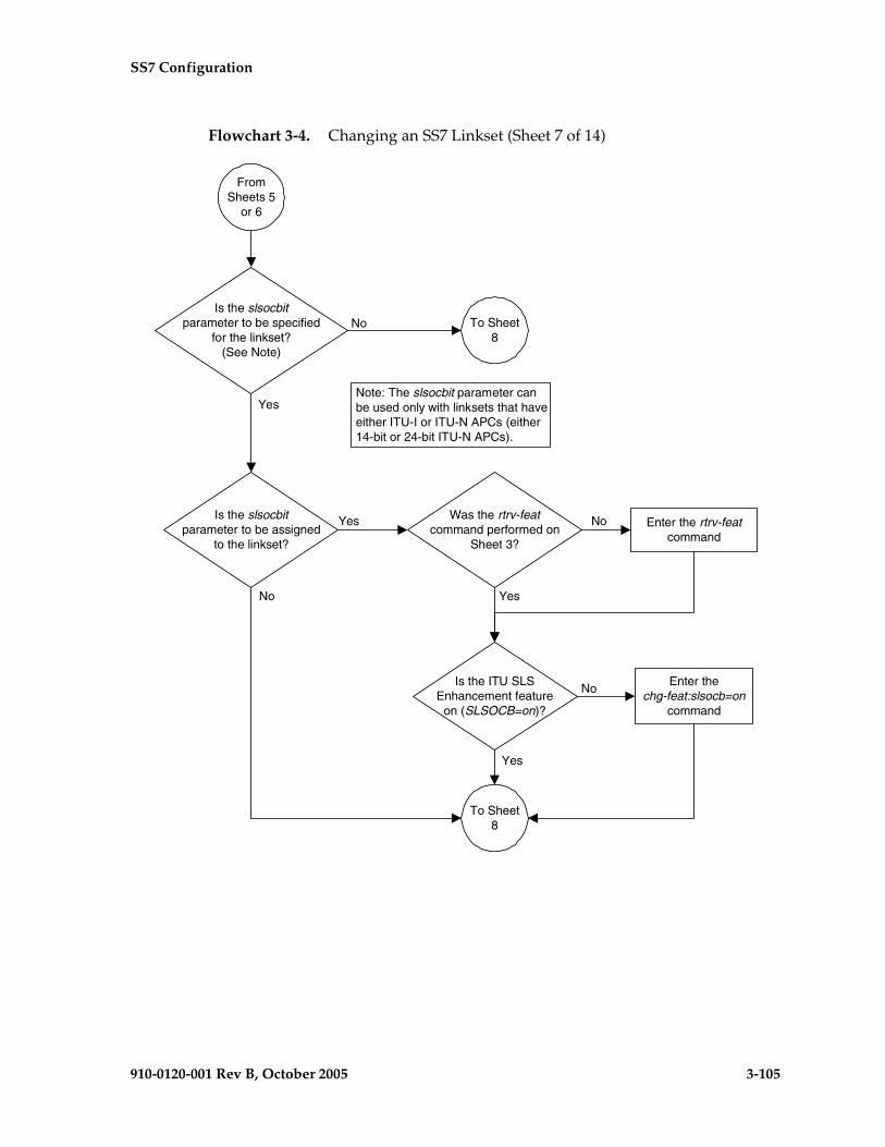
SS7 Configuration
910-0120-001 Rev B, October 2005 3-105
Flowchart 3-4. Changing an SS7 Linkset (Sheet 7 of 14)
Is the ITU SLSEnhancement feature
on (SLSOCB=on)?
Enter the rtrv-featcommand
Enter thechg-feat:slsocb=on
command
Is the slsocbitparameter to be assigned
to the linkset?
FromSheets 5
or 6
Yes
No
To Sheet8
Yes
No
Is the slsocbitparameter to be specified
for the linkset?(See Note)
No
Yes
To Sheet8
Note: The slsocbit parameter canbe used only with linksets that haveeither ITU-I or ITU-N APCs (either14-bit or 24-bit ITU-N APCs).
Was the rtrv-featcommand performed on
Sheet 3?
Yes
No
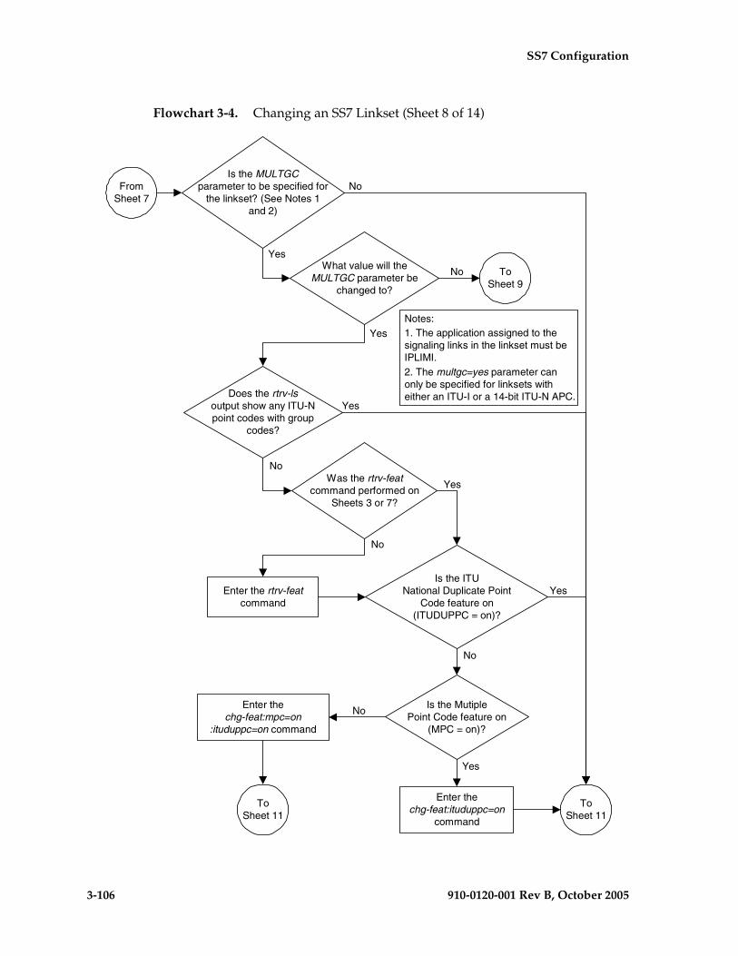
3-106 910-0120-001 Rev B, October 2005
SS7 Configuration
Flowchart 3-4. Changing an SS7 Linkset (Sheet 8 of 14)
Is the MutiplePoint Code feature on
(MPC = on)?
Is the ITUNational Duplicate Point
Code feature on(ITUDUPPC = on)?
Does the rtrv-lsoutput show any ITU-Npoint codes with group
codes?
Is the MULTGCparameter to be specified for
the linkset? (See Notes 1and 2)
Enter thechg-feat:mpc=on
:ituduppc=on command
Enter thechg-feat:ituduppc=on
command
Enter the rtrv-featcommand
Yes
No
No
No
Yes
Yes
Yes
No
Notes:1. The application assigned to thesignaling links in the linkset must beIPLIMI.2. The multgc=yes parameter canonly be specified for linksets witheither an ITU-I or a 14-bit ITU-N APC.
FromSheet 7
ToSheet 11
What value will theMULTGC parameter be
changed to?
Yes
No ToSheet 9
Was the rtrv-featcommand performed on
Sheets 3 or 7?
Yes
No
ToSheet 11

SS7 Configuration
910-0120-001 Rev B, October 2005 3-107
Flowchart 3-4. Changing an SS7 Linkset (Sheet 9 of 14)

3-108 910-0120-001 Rev B, October 2005
SS7 Configuration
Flowchart 3-4. Changing an SS7 Linkset (Sheet 10 of 14)

SS7 Configuration
910-0120-001 Rev B, October 2005 3-109
Flowchart 3-4. Changing an SS7 Linkset (Sheet 11 of 14)

3-110 910-0120-001 Rev B, October 2005
SS7 Configuration
Flowchart 3-4. Changing an SS7 Linkset (Sheet 12 of 14)
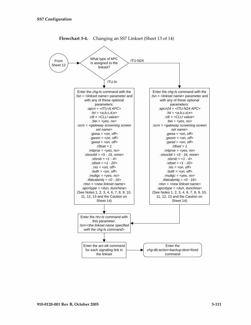
SS7 Configuration
910-0120-001 Rev B, October 2005 3-111
Flowchart 3-4. Changing an SS7 Linkset (Sheet 13 of 14)
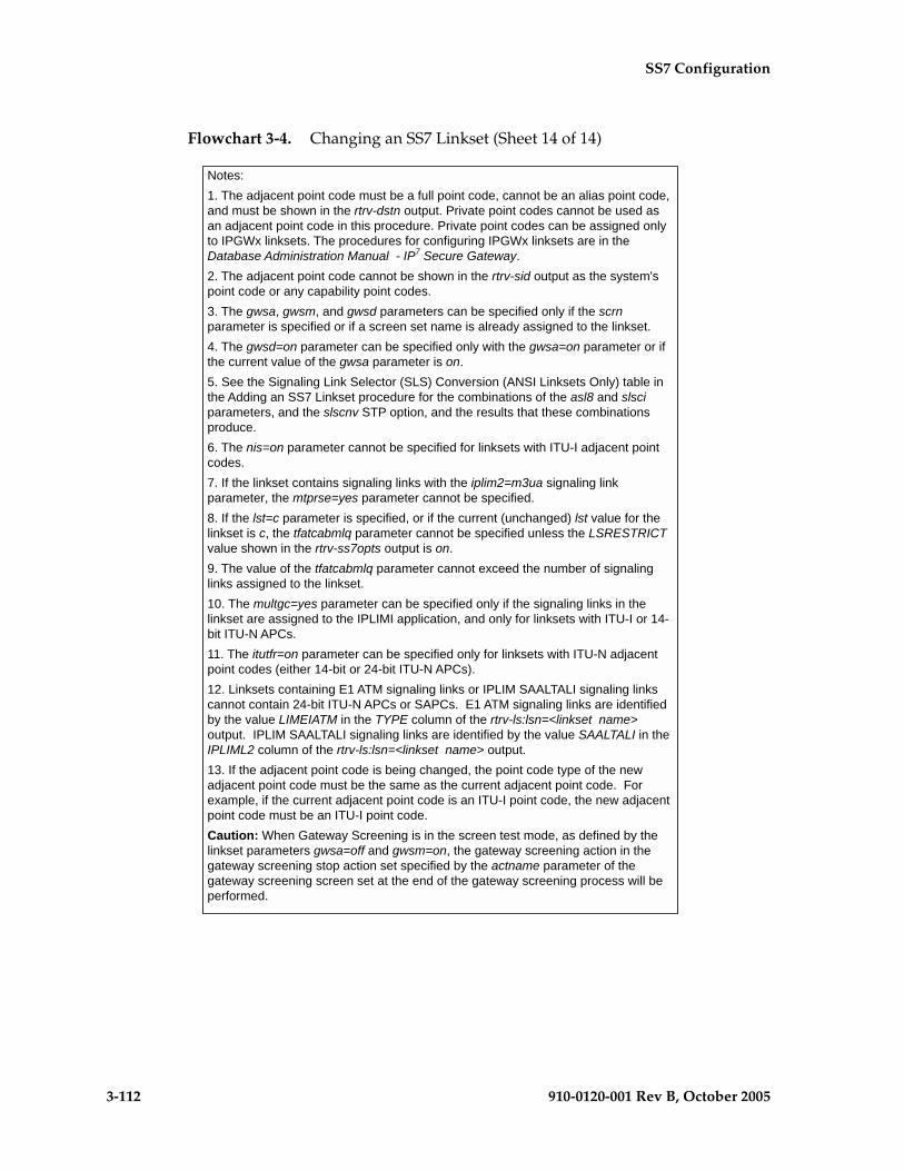
3-112 910-0120-001 Rev B, October 2005
SS7 Configuration
Flowchart 3-4. Changing an SS7 Linkset (Sheet 14 of 14)

SS7 Configuration
910-0120-001 Rev B, October 2005 3-113
Configuring an ITU Linkset with a Secondary Adjacent Point Code (SAPC)
This procedure is used to configure a secondary adjacent point code for SS7 ITU linksets using the lsn, sapci, sapcn, sapcn24, and action parameters of the chg-ls command. Only these parameters can be specified in this procedure. The chg-ls command contains other parameters. These parameters are explained in more detail in the “Changing an SS7 Linkset” procedure on page 3-74 and in these procedures in the Database Administration Manual - IP7 Secure Gateway.
• “Configuring an IPGWx Linkset”
• “Configuring a Mate IPGWx Linkset”
The secondary adjacent point code is used to enhance the network management in the ITU international and ITU national nodes when messages from different countries to be routed over the same linkset.
The lsn parameter specifies the name of the linkset being changed.
The sapci parameter specifies the ITU international secondary adjacent point code.
The sapcn parameter specifies a 14-bit ITU national secondary adjacent point code.
The sapcn24 parameter specifies a 24-bit ITU national secondary adjacent point code.
The action parameter specifies whether the secondary adjacent point code (sacpi, sapcn, or sapcn24) is being added (action=add) to the linkset or removed (action=delete) from the linkset.
While the multgc parameter is not specified with the chg-ls command in this procedure, in addition to specifying whether or not multiple group codes are supported for the linkset, its value does help determine how secondary adjacent point codes are configured in the linkset.
When this parameter value is yes, and the APC of the linkset is a 14-bit ITU national point code, the linkset can contain one 14-bit ITU national secondary adjacent point code for each group code in the EAGLE 5 SAS, and one ITU international secondary adjacent point code. If the APC of the linkset is ITU international, the linkset can contain either one 14-bit ITU national secondary adjacent point code for each group code in the EAGLE 5 SAS, or only one 24-bit ITU national secondary adjacent point code, but no ITU international secondary adjacent point codes.
If the APC of the linkset is a 24-bit ITU national point code, the linkset contains only one ITU international secondary adjacent point code.
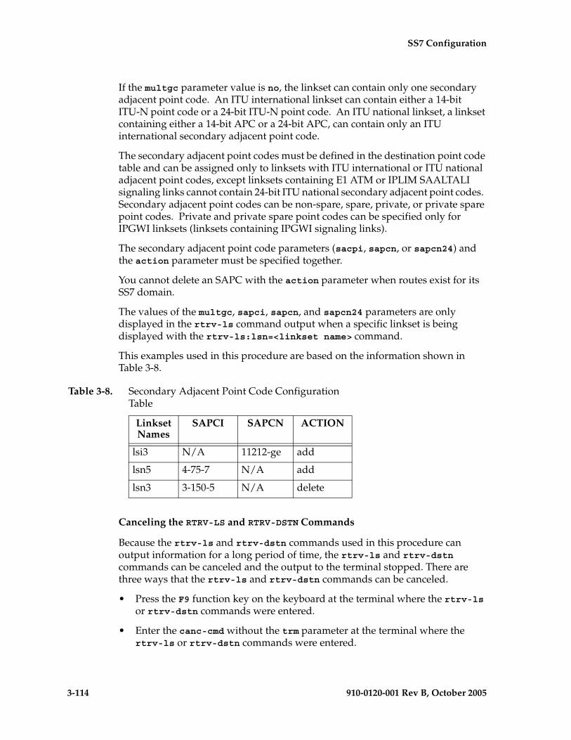
3-114 910-0120-001 Rev B, October 2005
SS7 Configuration
If the multgc parameter value is no, the linkset can contain only one secondary adjacent point code. An ITU international linkset can contain either a 14-bit ITU-N point code or a 24-bit ITU-N point code. An ITU national linkset, a linkset containing either a 14-bit APC or a 24-bit APC, can contain only an ITU international secondary adjacent point code.
The secondary adjacent point codes must be defined in the destination point code table and can be assigned only to linksets with ITU international or ITU national adjacent point codes, except linksets containing E1 ATM or IPLIM SAALTALI signaling links cannot contain 24-bit ITU national secondary adjacent point codes. Secondary adjacent point codes can be non-spare, spare, private, or private spare point codes. Private and private spare point codes can be specified only for IPGWI linksets (linksets containing IPGWI signaling links).
The secondary adjacent point code parameters (sacpi, sapcn, or sapcn24) and the action parameter must be specified together.
You cannot delete an SAPC with the action parameter when routes exist for its SS7 domain.
The values of the multgc, sapci, sapcn, and sapcn24 parameters are only displayed in the rtrv-ls command output when a specific linkset is being displayed with the rtrv-ls:lsn=<linkset name> command.
This examples used in this procedure are based on the information shown in Table 3-8.
Canceling the RTRV-LS and RTRV-DSTN Commands
Because the rtrv-ls and rtrv-dstn commands used in this procedure can output information for a long period of time, the rtrv-ls and rtrv-dstn commands can be canceled and the output to the terminal stopped. There are three ways that the rtrv-ls and rtrv-dstn commands can be canceled.
• Press the F9 function key on the keyboard at the terminal where the rtrv-ls or rtrv-dstn commands were entered.
• Enter the canc-cmd without the trm parameter at the terminal where the rtrv-ls or rtrv-dstn commands were entered.
Table 3-8. Secondary Adjacent Point Code Configuration Table
Linkset Names
SAPCI SAPCN ACTION
lsi3 N/A 11212-ge add
lsn5 4-75-7 N/A add
lsn3 3-150-5 N/A delete

SS7 Configuration
910-0120-001 Rev B, October 2005 3-115
• Enter the canc-cmd:trm=<xx>, where <xx> is the terminal where the rtrv-ls or rtrv-dstn commands were entered, from another terminal other that the terminal where the rtrv-ls or rtrv-dstn commands were entered. To enter the canc-cmd:trm=<xx> command, the terminal must allow Security Administration commands to be entered from it and the user must be allowed to enter Security Administration commands. The terminal’s permissions can be verified with the rtrv-secu-trm command. The user’s permissions can be verified with the rtrv-user or rtrv-secu-user commands.
For more information about the canc-cmd command, go to the Commands Manual.
Procedure
1. Display the current linkset configuration using the rtrv-ls command. This is an example of the possible output.
rlghncxa03w 05-09-10 11:43:04 GMT EAGLE5 34.0.0
L3T SLT GWS GWS GWSLSN APCA (SS7) SCRN SET SET BEI LST LNKS ACT MES DIS SLSCI NISe1e2 001-207-000 none 1 1 no B 6 off off off no offls1305 000-005-000 none 1 1 no A 1 off off off no offls1307 000-007-000 none 1 1 no A 1 off off off no offe1m1s1 001-001-001 none 1 1 no A 7 off off off no offe1m1s2 001-001-002 none 1 1 no A 7 off off off no off
L3T SLT GWS GWS GWSLSN APCA (X25) SCRN SET SET BEI LST LNKS ACT MES DIS SLSCI NIS
L3T SLT GWS GWS GWSLSN APCI (SS7) SCRN SET SET BEI LST LNKS ACT MES DIS SLSCI NISe1e2i 1-207-0 none 1 1 no B 4 off off off --- onls1315 0-015-0 none 1 1 no A 1 off off off --- offls1317 0-017-0 none 1 1 no A 1 off off off --- one1m2s1 1-011-1 none 1 1 no A 7 off off off --- offe1m2s2 1-011-2 none 1 1 no A 7 off off off --- off
L3T SLT GWS GWS GWSLSN APCN (SS7) SCRN SET SET BEI LST LNKS ACT MES DIS SLSCI NIS
L3T SLT GWS GWS GWSLSN APCN24 (SS7) SCRN SET SET BEI LST LNKS ACT MES DIS SLSCI NIS
L3T SLT GWS GWS GWSLSN (CHINA) APCN (SS7) SCRN SET SET BEI LST LNKS ACT MES DIS SLSCI NIS
L3T SLT GWS GWS GWSLSN (CHINA) APCN24 (SS7) SCRN SET SET BEI LST LNKS ACT MES DIS SLSCI NIS
Link set table is (10 of 1024) 1% full.

3-116 910-0120-001 Rev B, October 2005
SS7 Configuration
2. Display the current linkset configuration of the linkset to be changed using the rtrv-ls command with the linkset name. For this example, enter this command.
rtrv-ls:lsn=lsi3
This is an example of the possible output.
rlghncxa03w 05-09-17 11:43:04 GMT EAGLE5 34.0.0
L3T SLT GWS GWS GWSLSN APCI (SS7) SCRN SET SET BEI LST LNKS ACT MES DIS SLSCI NISlsi3 1-111-3 scr3 1 3 yes c 1 off off off --- ---
CLLI TFATCABMLQ MTPRSE ASL8 SLSRSB MULTGC ITUTFR ----------- 1 --- --- 7 yes off
IPGWAPC no
L2T L1 PCR PCR LOC LINK SLC TYPE SET BPS MODE TSET ECM N1 N2 1317 A 0 IPGWI
LP ATM LOC LINK SLC TYPE SET BPS TSEL VCI VPI LL
LP ATM E1ATM LOC LINK SLC TYPE SET BPS TSEL VCI VPI CRC4 SI SN
LOC LINK SLC TYPE IPLIML2
LOC LINK SLC TYPE
L2T PCR PCR E1 E1 LOC LINK SLC TYPE SET BPS ECM N1 N2 LOC PORT TS
L2T PCR PCR T1 T1 LOC LINK SLC TYPE SET BPS ECM N1 N2 LOC PORT TS
SAPCN 11211-uk
Link set table is ( 13 of 255) 5% full
rtrv-ls:lsn=lsn3
This is an example of the possible output.
rlghncxa03w 05-09-17 11:43:04 GMT EAGLE5 34.0.0
L3T SLT GWS GWS GWSLSN APCN (SS7) SCRN SET SET BEI LST LNKS ACT MES DIS SLSCI NISlsn3 11113-ge scr3 1 3 yes c 1 on off off --- off
CLLI TFATCABMLQ MTPRSE ASL8 SLSOCB MULTGC ITUTFR ----------- 1 --- --- 7 yes off
IPGWAPC no
L2T L1 PCR PCR LOC LINK SLC TYPE SET BPS MODE TSET ECM N1 N2

SS7 Configuration
910-0120-001 Rev B, October 2005 3-117
1301 A 0 IPLIMI
LP ATM LOC LINK SLC TYPE SET BPS TSEL VCI VPI LL
LP ATM E1ATM LOC LINK SLC TYPE SET BPS TSEL VCI VPI CRC4 SI SN
LOC LINK SLC TYPE IPLIML2
LOC LINK SLC TYPE
L2T PCR PCR E1 E1 LOC LINK SLC TYPE SET BPS ECM N1 N2 LOC PORT TS
L2T PCR PCR T1 T1 LOC LINK SLC TYPE SET BPS ECM N1 N2 LOC PORT TS
SAPCI 3-150-5
SAPCN 11213-de
Link set table is ( 13 of 255) 5% full
rtrv-ls:lsn=lsn5
This is an example of the possible output.
rlghncxa03w 05-09-17 11:43:04 GMT EAGLE5 34.0.0
L3T SLT GWS GWS GWSLSN APCN (SS7) SCRN SET SET BEI LST LNKS ACT MES DIS SLSCI NISlsn5 10685-fr scr1 1 3 yes a 1 off off off --- off
CLLI TFATCABMLQ MTPRSE ASL8 SLSOCB MULTGC ITUTFR ----------- 1 --- --- 7 no off
IPGWAPC no
L2T L1 PCR PCR LOC LINK SLC TYPE SET BPS MODE TSET ECM N1 N2 1201 A 0 IPLIMI
LP ATM LOC LINK SLC TYPE SET BPS TSEL VCI VPI LL
LP ATM E1ATM LOC LINK SLC TYPE SET BPS TSEL VCI VPI CRC4 SI SN
LOC LINK SLC TYPE IPLIML2
LOC LINK SLC TYPE
L2T PCR PCR E1 E1 LOC LINK SLC TYPE SET BPS ECM N1 N2 LOC PORT TS
L2T PCR PCR T1 T1 LOC LINK SLC TYPE SET BPS ECM N1 N2 LOC PORT TS
Link set table is ( 13 of 255) 5% full

3-118 910-0120-001 Rev B, October 2005
SS7 Configuration
If 24-bit ITU-N secondary adjacent point codes are being added to the linkset, and the linkset specified in this step contains E1 ATM or IPLIM SAALTALI signaling links, choose another linkset from step 1 and repeat this step. Linksets containing E1 ATM or IPLIM SAALTALI signaling links cannot have 24-bit ITU-N secondary adjacent point codes.
NOTE: If you are not adding any secondary adjacent point codes to the linkset, skip steps 3 and 4, and go to step 5.
3. Display the point code and capability point code of the EAGLE 5 SAS by using the rtrv-sid command. This is an example of the possible output.
rlghncxa03w 05-09-10 11:43:04 GMT EAGLE5 34.0.0 PCA PCI PCN CLLI PCTYPE 001-001-001 3-150-4 12345-uk rlghncxa03w OTHER
CPCA 002-002-002 002-002-003 002-002-004 002-002-005 002-002-006 002-002-007 002-002-008 002-002-009 004-002-001 004-003-003 144-212-003
CPCI 1-001-1 1-001-2 1-001-3 1-001-4
CPCN 02091-uk 02092-uk 02094-uk 02097-uk 02191-uk 02192-uk 11177-uk
4. Display the point codes in the destination point code table by using the rtrv-dstn command. This is an example of the possible output.
rlghncxa03w 05-09-10 11:43:04 GMT EAGLE5 34.0.0 DPCA CLLI BEI ELEI ALIASI ALIASN/N24 DOMAIN 001-002-003 ls04clli yes --- ---------- -------------- SS7 001-002-003 ls04clli yes --- ---------- -------------- SS7 002-002-100 ls01clli no --- ---------- -------------- SS7 002-007-008 ls06clli yes --- ---------- -------------- SS7 002-009-003 -------- no --- ---------- -------------- SS7 002-250-010 -------- no --- ---------- -------------- SS7 003-003-003 ls03clli yes --- ---------- -------------- SS7 003-020-100 -------- no --- ---------- -------------- SS7 004-004-004 ls02clli yes --- ---------- -------------- SS7 004-030-200 -------- no --- ---------- -------------- SS7 009-002-003 -------- no --- ---------- -------------- SS7 179-100-087 -------- yes --- ---------- -------------- SS7 200-050-176 -------- yes --- ---------- -------------- SS7 240-007-000 -------- yes --- ---------- -------------- SS7 240-012--004 rlghncbb001 yes --- 1-111-1 11111 SS7 240-012-005 rlghncbb002 yes --- 1-112-2 11112 SS7 240-012-008 -------- yes --- 1-113-5 11114 SS7 244-010-004 ls06clli no --- ---------- -------------- X25 244-012-005 ls07clli no --- ---------- -------------- X25 244-012-006 ls08clli no --- ---------- -------------- X25 244-012-007 -------- no --- ---------- -------------- X25 244-012-008 -------- no --- ---------- -------------- X25
DPCI CLLI BEI ELEI ALIASA ALIASN/N24 DOMAIN 2-131-1 rlghncbb023 no --- 222-210-000 12001 SS7 2-131-2 -------- no --- 222-211-001 12002 SS7
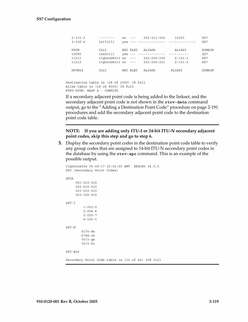
SS7 Configuration
910-0120-001 Rev B, October 2005 3-119
2-131-3 -------- no --- 222-211-002 12003 SS7 3-150-4 lsi7clli yes --- -------------- -------------- SS7
DPCN CLLI BEI ELEI ALIASA ALIASI DOMAIN 10685 lsn5clli yes --- -------------- ---------- SS7 11211 rlghncbb013 no --- 222-200-200 2-121-1 SS7 11212 rlghncbb013 no --- 222-200-201 2-121-2 SS7
DPCN24 CLLI BEI ELEI ALIASA ALIASI DOMAIN
Destination table is (28 of 2000) 1% fullAlias table is (18 of 8000) 1% fullRTRV-DSTN: MASP A - COMPLTD
If a secondary adjacent point code is being added to the linkset, and the secondary adjacent point code is not shown in the rtrv-dstn command output, go to the “Adding a Destination Point Code” procedure on page 2-191 procedures and add the secondary adjacent point code to the destination point code table.7
NOTE: If you are adding only ITU-I or 24-bit ITU-N secondary adjacent point codes, skip this step and go to step 6.
5. Display the secondary point codes in the destination point code table to verify any group codes that are assigned to 14-bit ITU-N secondary point codes in the database by using the rtrv-spc command. This is an example of the possible output.
rlghncxa03w 05-09-17 16:02:05 GMT EAGLE5 34.0.0SPC (Secondary Point Codes)
SPCA 001-010-010 002-010-010 003-010-010 010-100-010
SPC-I 1-253-5 2-254-6 3-255-7 4-100-1
SPC-N 5175-de 6744-uk 7673-ge 7673-fr
SPC-N24
Secondary Point Code table is (12 of 40) 30% full
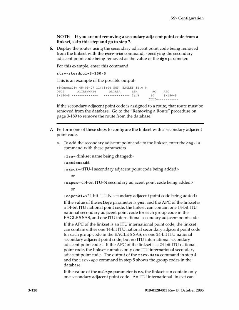
3-120 910-0120-001 Rev B, October 2005
SS7 Configuration
NOTE: If you are not removing a secondary adjacent point code from a linkset, skip this step and go to step 7.
6. Display the routes using the secondary adjacent point code being removed from the linkset with the rtrv-rte command, specifying the secondary adjacent point code being removed as the value of the dpc parameter.
For this example, enter this command.
rtrv-rte:dpci=3-150-5
This is an example of the possible output.
rlghncxa03w 05-09-07 11:43:04 GMT EAGLE5 34.0.0DPCI ALIASN/N24 ALIASA LSN RC APC3-150-5 -------------- -------------- lsn3 10 3-150-5 CLLI=-----------
If the secondary adjacent point code is assigned to a route, that route must be removed from the database. Go to the “Removing a Route” procedure on page 3-189 to remove the route from the database.
7. Perform one of these steps to configure the linkset with a secondary adjacent point code.
a. To add the secondary adjacent point code to the linkset, enter the chg-ls command with these parameters.
:lsn=<linkset name being changed>:action=add
:sapci=<ITU-I secondary adjacent point code being added>
or
:sapcn=<14-bit ITU-N secondary adjacent point code being added>
or
:sapcn24=<24-bit ITU-N secondary adjacent point code being added>
If the value of the multgc parameter is yes, and the APC of the linkset is a 14-bit ITU national point code, the linkset can contain one 14-bit ITU national secondary adjacent point code for each group code in the EAGLE 5 SAS, and one ITU international secondary adjacent point code.
If the APC of the linkset is an ITU international point code, the linkset can contain either one 14-bit ITU national secondary adjacent point code for each group code in the EAGLE 5 SAS, or one 24-bit ITU national secondary adjacent point code, but no ITU international secondary adjacent point codes. If the APC of the linkset is a 24-bit ITU national point code, the linkset contains only one ITU international secondary adjacent point code. The output of the rtrv-dstn command in step 4 and the rtrv-spc command in step 5 shows the group codes in the database.
If the value of the multgc parameter is no, the linkset can contain only one secondary adjacent point code. An ITU international linkset can
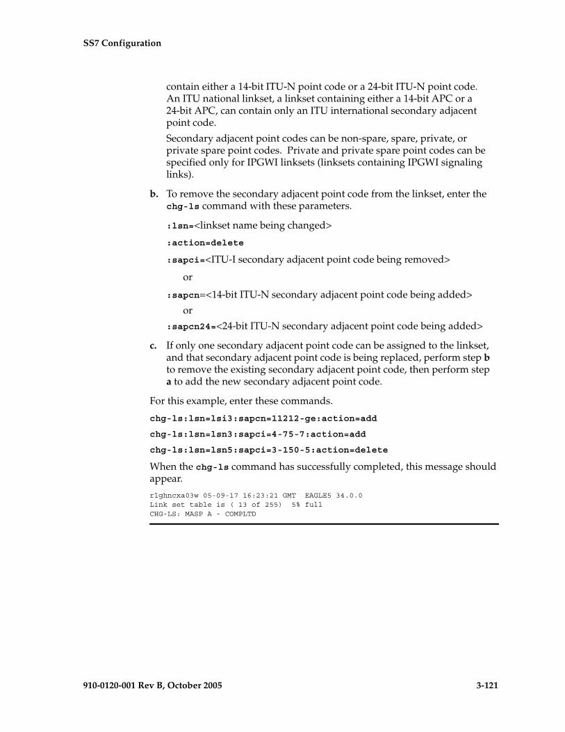
SS7 Configuration
910-0120-001 Rev B, October 2005 3-121
contain either a 14-bit ITU-N point code or a 24-bit ITU-N point code. An ITU national linkset, a linkset containing either a 14-bit APC or a 24-bit APC, can contain only an ITU international secondary adjacent point code.
Secondary adjacent point codes can be non-spare, spare, private, or private spare point codes. Private and private spare point codes can be specified only for IPGWI linksets (linksets containing IPGWI signaling links).
b. To remove the secondary adjacent point code from the linkset, enter the chg-ls command with these parameters.
:lsn=<linkset name being changed>
:action=delete
:sapci=<ITU-I secondary adjacent point code being removed>
or
:sapcn=<14-bit ITU-N secondary adjacent point code being added>
or
:sapcn24=<24-bit ITU-N secondary adjacent point code being added>
c. If only one secondary adjacent point code can be assigned to the linkset, and that secondary adjacent point code is being replaced, perform step b to remove the existing secondary adjacent point code, then perform step a to add the new secondary adjacent point code.
For this example, enter these commands.
chg-ls:lsn=lsi3:sapcn=11212-ge:action=add
chg-ls:lsn=lsn3:sapci=4-75-7:action=add
chg-ls:lsn=lsn5:sapci=3-150-5:action=delete
When the chg-ls command has successfully completed, this message should appear.
rlghncxa03w 05-09-17 16:23:21 GMT EAGLE5 34.0.0Link set table is ( 13 of 255) 5% fullCHG-LS: MASP A - COMPLTD

3-122 910-0120-001 Rev B, October 2005
SS7 Configuration
8. Verify the changes using the rtrv-ls command specifying the linkset name specified in step 7 with the lsn parameter. For this example, enter these commands.
rtrv-ls:lsn=lsi3
This is an example of the possible output.
rlghncxa03w 05-09-17 11:43:04 GMT EAGLE5 34.0.0
L3T SLT GWS GWS GWSLSN APCI (SS7) SCRN SET SET BEI LST LNKS ACT MES DIS SLSCI NISlsi3 1-111-3 scr3 1 3 yes c 1 off off off --- ---
CLLI TFATCABMLQ MTPRSE ASL8 SLSRSB MULTGC ITUTFR ----------- 1 --- --- 7 yes off
IPGWAPC no
L2T L1 PCR PCR LOC LINK SLC TYPE SET BPS MODE TSET ECM N1 N2 1317 A 0 IPGWI
LP ATM LOC LINK SLC TYPE SET BPS TSEL VCI VPI LL
LP ATM E1ATM LOC LINK SLC TYPE SET BPS TSEL VCI VPI CRC4 SI SN
LOC LINK SLC TYPE IPLIML2
LOC LINK SLC TYPE
L2T PCR PCR E1 E1 LOC LINK SLC TYPE SET BPS ECM N1 N2 LOC PORT TS
L2T PCR PCR T1 T1 LOC LINK SLC TYPE SET BPS ECM N1 N2 LOC PORT TS
SAPCN 11211-uk 11212-ge
Link set table is ( 13 of 255) 5% full
rtrv-ls:lsn=lsn3
This is an example of the possible output.
rlghncxa03w 05-09-17 11:43:04 GMT EAGLE5 34.0.0
L3T SLT GWS GWS GWSLSN APCN (SS7) SCRN SET SET BEI LST LNKS ACT MES DIS SLSCI NISlsn3 11113-ge scr3 1 3 yes c 1 on off off --- off
CLLI TFATCABMLQ MTPRSE ASL8 SLSOCB MULTGC ITUTFR ----------- 1 --- --- 7 yes off
IPGWAPC no

SS7 Configuration
910-0120-001 Rev B, October 2005 3-123
L2T L1 PCR PCR LOC LINK SLC TYPE SET BPS MODE TSET ECM N1 N2 1301 A 0 IPLIMI
LP ATM LOC LINK SLC TYPE SET BPS TSEL VCI VPI LL
LP ATM E1ATM LOC LINK SLC TYPE SET BPS TSEL VCI VPI CRC4 SI SN
LOC LINK SLC TYPE IPLIML2
LOC LINK SLC TYPE
L2T PCR PCR E1 E1 LOC LINK SLC TYPE SET BPS ECM N1 N2 LOC PORT TS
L2T PCR PCR T1 T1 LOC LINK SLC TYPE SET BPS ECM N1 N2 LOC PORT TS
SAPCN 11213-de
Link set table is ( 13 of 255) 5% full
rtrv-ls:lsn=lsn5
This is an example of the possible output.
rlghncxa03w 05-09-17 11:43:04 GMT EAGLE5 34.0.0
L3T SLT GWS GWS GWSLSN APCN (SS7) SCRN SET SET BEI LST LNKS ACT MES DIS SLSCI NISlsn5 10685-fr scr1 1 3 yes a 1 off off off --- off
CLLI TFATCABMLQ MTPRSE ASL8 SLSOCB MULTGC ITUTFR ----------- 1 --- --- 7 no off
IPGWAPC no
L2T L1 PCR PCR LOC LINK SLC TYPE SET BPS MODE TSET ECM N1 N2 1201 A 0 IPLIMI
LP ATM LOC LINK SLC TYPE SET BPS TSEL VCI VPI LL
LP ATM E1ATM LOC LINK SLC TYPE SET BPS TSEL VCI VPI CRC4 SI SN
LOC LINK SLC TYPE IPLIML2
LOC LINK SLC TYPE
L2T PCR PCR E1 E1 LOC LINK SLC TYPE SET BPS ECM N1 N2 LOC PORT TS
L2T PCR PCR T1 T1 LOC LINK SLC TYPE SET BPS ECM N1 N2 LOC PORT TS
SAPCI 4-75-7
Link set table is ( 13 of 255) 5% full

3-124 910-0120-001 Rev B, October 2005
SS7 Configuration
9. Back up the new changes using the chg-db:action=backup:dest=fixed command. These messages should appear, the active Maintenance and Administration Subsystem Processor (MASP) appears first.
BACKUP (FIXED) : MASP A - Backup starts on active MASP.BACKUP (FIXED) : MASP A - Backup on active MASP to fixed disk complete.BACKUP (FIXED) : MASP A - Backup starts on standby MASP.BACKUP (FIXED) : MASP A - Backup on standby MASP to fixed disk complete.

SS7 Configuration
910-0120-001 Rev B, October 2005 3-125
Flowchart 3-5. Configuring an ITU Linkset with a Secondary Adjacent Point Code (SAPC) (Sheet 1 of 5)
Is the requiredpoint code in
the DPC table?
Enter the rtrv-dstncommand
No
Yes
Enter the rtrv-lscommand
Enter the rtrv-sidcommand
Go to the "Adding aDestination Point Code"procedure and add the
required point code to theDPC table
Are any SAPCsto be added to the
linkset?
No
Yes
ToSheet 2
Enter thertrv-ls:lsn=<linkset name>
command
ToSheet 3
FromSheet 2
Are any 24-bitITU-N SAPCs to be added
to the linkset, or does the linksetcontain a 24-bit APCN
(APCN24)?
No
YesDoes the linkset
contain E1 ATM or IPLIMSAALTALI signaling
links?
Choose another linkset.Linksets containing E1 ATMor IPLIM SAALTALI signaling
links cannot contain 24-bitITU-N APCs or SAPCs.
No
Yes

3-126 910-0120-001 Rev B, October 2005
SS7 Configuration
Flowchart 3-5. Configuring an ITU Linkset with a Secondary Adjacent Point Code (SAPC) (Sheet 2 of 5)
Enter thechg-ls command with these parameters:
:lsn=<linkset name being changed>:action=deleteand with one of these parameterscorresponding to the SAPC beingremoved::sapci=<ITU-I SAPC>:sapcn=<14-bit ITU-N SAPC>:sapcn24=<24-bit ITU-N SAPC>
FromSheet 1
Enter thertrv-ls:lsn=<linkset name>
command
Enter thechg-db:action=backup:dest=fixed
command
Enter thertrv-rte command with one of these
parameters corresponding to the SAPC beingremoved:
:dpci=<ITU-I SAPC being removed>:dpcn=<14-bit ITU-N SAPC being removed>
:dpcn24=<24-bit ITU-N SAPC beingremoved>
Is the SAPC theDPC of a route?
Go to the "Removing a Route"procedure and remove the
route to the SAPC
Yes
No
Is an SAPC to beadded to the linkset?
Yes
No
ToSheet 1
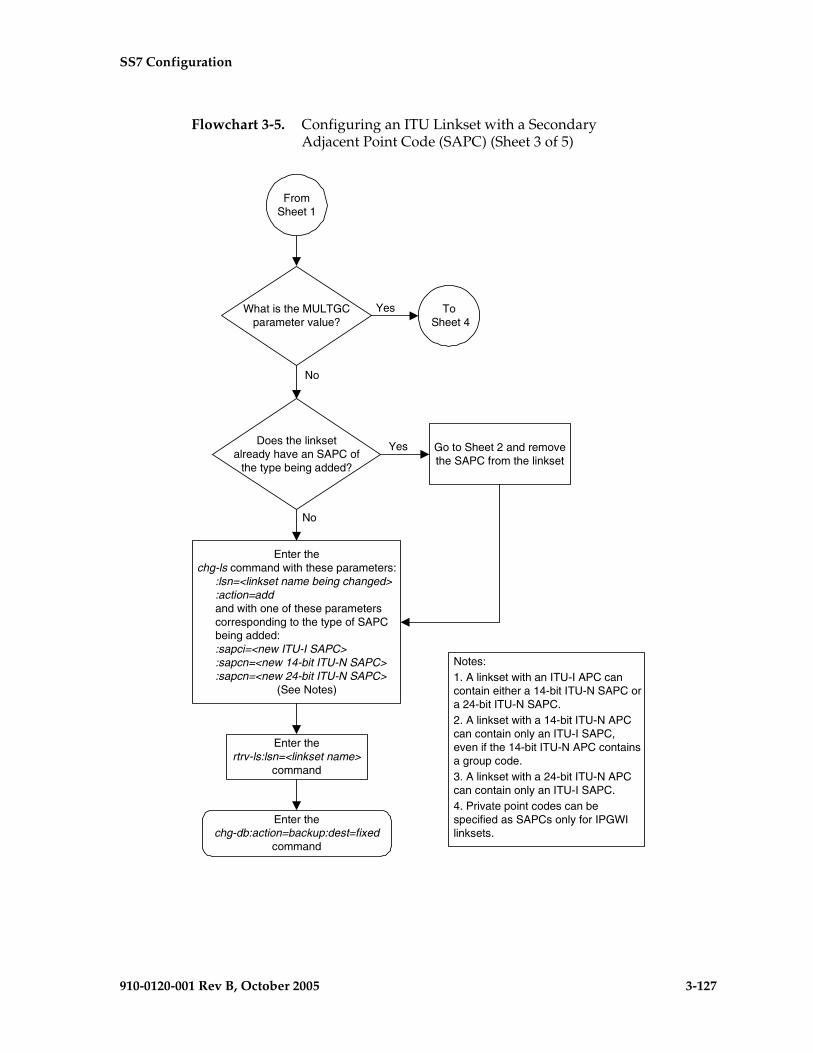
SS7 Configuration
910-0120-001 Rev B, October 2005 3-127
Flowchart 3-5. Configuring an ITU Linkset with a Secondary Adjacent Point Code (SAPC) (Sheet 3 of 5)
FromSheet 1
Does the linksetalready have an SAPC of
the type being added?
No
Yes
Enter thertrv-ls:lsn=<linkset name>
command
What is the MULTGCparameter value?
Enter thechg-db:action=backup:dest=fixed
command
To Sheet 4
Yes
Enter thechg-ls command with these parameters:
:lsn=<linkset name being changed>:action=addand with one of these parameterscorresponding to the type of SAPCbeing added::sapci=<new ITU-I SAPC>:sapcn=<new 14-bit ITU-N SAPC>:sapcn=<new 24-bit ITU-N SAPC>
(See Notes)
Notes:1. A linkset with an ITU-I APC cancontain either a 14-bit ITU-N SAPC ora 24-bit ITU-N SAPC.2. A linkset with a 14-bit ITU-N APCcan contain only an ITU-I SAPC,even if the 14-bit ITU-N APC containsa group code.3. A linkset with a 24-bit ITU-N APCcan contain only an ITU-I SAPC.4. Private point codes can bespecified as SAPCs only for IPGWIlinksets.
No
Go to Sheet 2 and removethe SAPC from the linkset

3-128 910-0120-001 Rev B, October 2005
SS7 Configuration
Flowchart 3-5. Configuring an ITU Linkset with a Secondary Adjacent Point Code (SAPC) (Sheet 4 of 5)
FromSheets 3
or 5
Enter thertrv-ls:lsn=<linkset name>
command
Enter thechg-db:action=backup:dest=fixed
command
Enter thechg-ls command with these
parameters:
:lsn=<linkset name beingchanged>:sapci=<new ITU-I SAPC>:action=add (See Notes)
Yes No
Notes:
1. A linkset with a 14-bit ITU-NAPC can contain only one ITU-ISAPC.
2. Private point codes can bespecified as SAPCs only forIPGWI linksets.
What type of SAPCis being added?
24-BitITU-N
Go to Sheet 3 and add the24-bit ITU-N SAPC. Thelinkset can contain onlyone 24-bit ITU-N SAPC.
ITU-I
14-Bit ITU-Npoint code witha group code
Does the linksetalready have an ITU-I
SAPC?
No
Yes Go to Sheet 2 andremove the SAPC from
the linkset
ToSheet 5
Are 14-bit ITU-NSAPCs to be added to
the linkset?

SS7 Configuration
910-0120-001 Rev B, October 2005 3-129
Flowchart 3-5. Configuring an ITU Linkset with a Secondary Adjacent Point Code (SAPC) (Sheet 5 of 5)
FromSheet 4
Enter thertrv-ls:lsn=<linkset name>
command
Enter thechg-db:action=backup:dest=fixed
command
Are other ITU-NSAPCs to be added to
the linkset?
Yes
No
Notes:1. A linkset with an ITU-I APC cancontain a 14-bit ITU-N SAPC witha group code, for every groupcode in shown in the rtrv-dstn andrtrv-spc outputs, and no ITU-ISAPCs.2. A linkset with a14-bit ITU-NAPC can contain a 14-bit ITU-NSAPC with a group code, forevery group code in shown in thertrv-dstn and rtrv-spc outputs, andone ITU-I SAPC.3. Private point codes can bespecified as SAPCs only forIPGWI linksets.
Enter thertrv-spc command
Enter the chg-ls command with theseparameters:
:lsn=<linkset name being changed>:sapcn=<new 14-bit ITU-N SAPC>:action=add (See Notes)
Is an ITU-ISAPC to be added to
the linkset?
Yes
No
ToSheet 3

3-130 910-0120-001 Rev B, October 2005
SS7 Configuration
Adding an SS7 Signaling Link
This procedure is used to add an SS7 low-speed signaling link to the database using the ent-slk command. To add other types of signaling links to the database, go to one of these procedures:
• An E1 signaling link, perform the “Adding an E1 Signaling Link” procedure on page A-77.
• A T1 signaling link, perform the “Adding a T1 Signaling Link” procedure on page B-47.
• An ATM high-speed signaling link (ANSI or E1), perform the “Adding an ATM High-Speed Signaling Link” procedure on page C-34.
• An IP signaling link, go to the “Adding an IP Signaling Link” procedure in the Database Administration Manual - IP7 Secure Gateway.
• An X.25 signaling link, go to the “Adding an X.25 Signaling Link” procedure in the Database Administration Manual – Features.
The ent-slk command uses these parameters.
:loc – The card location of the LIM that the SS7 signaling link will be assigned to. The cards specified by this parameter are LIM-DS0, LIMOCU, LIMV.35.
:link – The signaling link on the card specified in the loc parameter.
:lsn – The name of the linkset that will contain the signaling link.
:slc – The signaling link code. The SLC must be unique within the linkset. It must be the same at both the EAGLE 5 SAS location and the distant node.
:l2tset – The level 2 timer set table. A signaling link may be assigned to any of the thirty tables. The type of linkset the signaling link is assigned to and the LIM’s application determines the value of the l2tset parameter. The level 2 timer set tables are defined in the “Changing Level 2 Timers” procedure on page 3-219. Table 3-9 on page 3-131 shows the l2tset parameter values.

SS7 Configuration
910-0120-001 Rev B, October 2005 3-131
:l1mode – The mode of operation used to select the link clocking source at layer 1. One end of a V.35 link must be DTE and the other end must be DCE.
:bps – The transmission rate for the link in bits per second.
:tset – Transmitter signal element timing
:ecm – Error correction method
:pcrn1 – The threshold of the number of MSUs available for retransmission. If the error correction method being used is PCR (:ecm=pcr), and this threshold is reached, no new MSUs or FISUs are sent. The retransmission cycle is continued up to the last MSU entered into the retransmission buffer in the order in which they were originally transmitted.
:pcrn2 – The threshold of the number of MSU octets available for retransmission. If the error correction method being used is PCR (:ecm=pcr), and this threshold is reached, no new MSUs or FISUs are sent. The retransmission cycle is continued up to the last MSU entered into the retransmission buffer in the order in which they were originally transmitted.
Table 3-9. L2TSET Parameter Values
Type of Linkset LIM’s Application
L2TSET Parameter
Value
L2TSET Parameter
Default Value
ANSI linkset – Shown by this label in the rtrv-ls output.LSN APCA (SS7)
SS7ANSI 1 - 10 1
ITU linkset – Shown by one of these labels in the rtrv-ls output.LSN APCI (SS7)LSN APCN (SS7)LSN APCN24 (SS7)
CCS7ITU 11 - 20 11
ITU-N high-speed linkset for China – Shown by one of these labels in the rtrv-ls output.LSN (CHINA) APCN (SS7)LSN (CHINA) APCN24 (SS7)
CCS7ITU 21 - 25 21
ITU-N high-speed linkset for countries other than China – Shown by one of these labels in the rtrv-ls output.LSN APCN (SS7)LSN APCN24 (SS7)
CCS7ITU 26 - 30 26
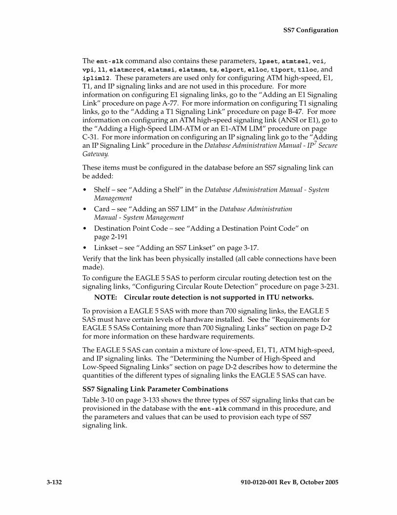
3-132 910-0120-001 Rev B, October 2005
SS7 Configuration
The ent-slk command also contains these parameters, lpset, atmtsel, vci, vpi, ll, e1atmcrc4, e1atmsi, e1atmsn, ts, e1port, e1loc, t1port, t1loc, and ipliml2. These parameters are used only for configuring ATM high-speed, E1, T1, and IP signaling links and are not used in this procedure. For more information on configuring E1 signaling links, go to the “Adding an E1 Signaling Link” procedure on page A-77. For more information on configuring T1 signaling links, go to the “Adding a T1 Signaling Link” procedure on page B-47. For more information on configuring an ATM high-speed signaling link (ANSI or E1), go to the “Adding a High-Speed LIM-ATM or an E1-ATM LIM” procedure on page C-31. For more information on configuring an IP signaling link go to the “Adding an IP Signaling Link” procedure in the Database Administration Manual - IP7 Secure Gateway.
These items must be configured in the database before an SS7 signaling link can be added:
• Shelf – see “Adding a Shelf” in the Database Administration Manual - System Management
• Card – see “Adding an SS7 LIM” in the Database Administration Manual - System Management
• Destination Point Code – see “Adding a Destination Point Code” on page 2-191
• Linkset – see “Adding an SS7 Linkset” on page 3-17.
Verify that the link has been physically installed (all cable connections have been made).
To configure the EAGLE 5 SAS to perform circular routing detection test on the signaling links, “Configuring Circular Route Detection” procedure on page 3-231.
NOTE: Circular route detection is not supported in ITU networks.
To provision a EAGLE 5 SAS with more than 700 signaling links, the EAGLE 5 SAS must have certain levels of hardware installed. See the “Requirements for EAGLE 5 SASs Containing more than 700 Signaling Links” section on page D-2 for more information on these hardware requirements.
The EAGLE 5 SAS can contain a mixture of low-speed, E1, T1, ATM high-speed, and IP signaling links. The “Determining the Number of High-Speed and Low-Speed Signaling Links” section on page D-2 describes how to determine the quantities of the different types of signaling links the EAGLE 5 SAS can have.
SS7 Signaling Link Parameter Combinations
Table 3-10 on page 3-133 shows the three types of SS7 signaling links that can be provisioned in the database with the ent-slk command in this procedure, and the parameters and values that can be used to provision each type of SS7 signaling link.

SS7 Configuration
910-0120-001 Rev B, October 2005 3-133
Table 3-10. SS7 Signaling Link Parameter Combinations
Low-Speed Signaling Link 1 MPL Signaling Link 1
Mandatory Parameters
:loc = location of the LIM with one of these applications: SS7ANSI, CCS7ITU; and one of these card types: LIMDS0, LIMOCU, LIMV35
:loc = location of the MPL with the SS7ANSI application and the LIMDS0 card type.
:link = A or B 8 :link = A, A1, A2, A3, B, B1, B2, or B38
:lsn = linkset name 2 :lsn = linkset name 7
:slc = 0 - 15 :slc = 0 - 15
Optional Parameters
:bps = 56000 or 64000 3
default value = 56000:bps = 56000default value = 56000
:l2tset = See Table 3-9 on page 3-131 :l2tset = Table 3-9 on page 3-131:ecm = basic or pcrdefault value = basic
:ecm = basic or pcrdefault value = basic
:pcrn1 = 1 - 127 4
default value = 76:pcrn1 = 1 - 127 4
default value = 76
:pcrn2 = 300 - 35500 4
default value = 3800:pcrn2 = 300 - 35500 4
default value = 3800
:l1mode = dte or dce 5
default value = dte
:tset = on or off 5, 6
default value = offNotes:1. This procedure is not used to configure ATM, X.25, IP, E1, or T1 signaling links. To configure these types of links, perform one
of these procedures:• E1 signaling links – “Adding an E1 Signaling Link” procedure on page A-77.• T1 signaling links – “Adding a T1 Signaling Link” procedure on page B-47.• ATM signaling links – “Adding an ATM High-Speed Signaling Link” procedure on page C-34.• IP signaling links – “Adding an IP Signaling Link” procedure in the Database Administration Manual - IP7 Secure Gateway.• X.25 signaling links – “Adding an X.25 Signaling Link” procedure in the Database Administration Manual - Features.
2. The linkset adjacent point code type (ITU/ANSI) must match the card’s application (CCS7ITU/SS7ANSI). The domain of the linkset adjacent point code must be SS7. A linkset can contain a maximum of 16 signaling links.
3. If the card type is LIMDS0 or LIMOCU, the value of this parameter must be 56000. All signaling links in a linkset must have the same transmission rate (bps parameter value).
4. These parameters can be specified only with the ecm=pcr parameter.5. These parameters can be specified only if the card type is LIMV35.6. This parameter can be specified only with the l1mode=dce parameter.7. The linkset adjacent point code type must be ANSI. The domain of the linkset adjacent point code must be SS7.8. The port parameter can be used in place of the link parameter to specify the signaling link on the card.

3-134 910-0120-001 Rev B, October 2005
SS7 Configuration
Example Signaling Link Configuration
This examples used in this procedure are based on the example network shown in Figure 3-3 and Table 3-11.
Table 3-11. Low-Speed Signaling Link Configuration Table
SLKLSN SLC TYPE L2TSET BPS
LOC LINK
1201 A LS01 0 LIMDS0 1 -----
1204 B LS01 1 LIMDS0 1 -----
1202 B LS02 0 LIMV35 2 64000
1206 A LS02 1 LIMV35 2 64000
1203 A LS03 0 LIMDS0 3 -----
1208 B LS03 1 LIMDS0 3 -----
1212 A LS04 1 LIMV35 4 64000
1213 B LS05 0 LIMDS0 5 -----
1215 A LS05 1 LIMDS0 5 -----
1301 B LS06 0 LIMV35 6 56000
1304 B LS06 1 LIMV35 6 56000
1308 A LS06 2 LIMV35 6 56000
1311 A LS01 2 LIMDS0 1 ----
1311 A1 LS05 2 LIMDS0 5 ----
1311 B LS03 2 LIMDS0 3 ----
1311 B1 LS07 1 LIMDS0 7 ----
1313 A LS07 0 LIMDS0 7 -----
1315 A LSN5 0 LIMV35 11 64000
1317 A LSI7 0 LIMV35 11 64000
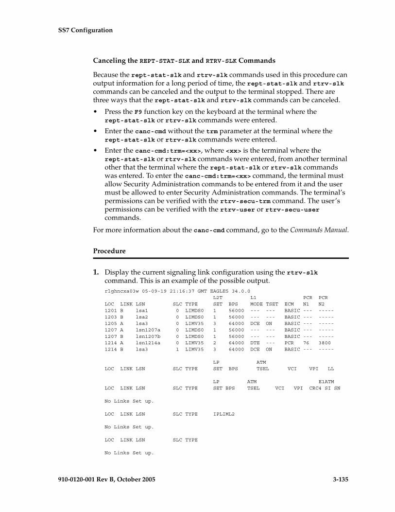
SS7 Configuration
910-0120-001 Rev B, October 2005 3-135
Canceling the REPT-STAT-SLK and RTRV-SLK Commands
Because the rept-stat-slk and rtrv-slk commands used in this procedure can output information for a long period of time, the rept-stat-slk and rtrv-slk commands can be canceled and the output to the terminal stopped. There are three ways that the rept-stat-slk and rtrv-slk commands can be canceled.
• Press the F9 function key on the keyboard at the terminal where the rept-stat-slk or rtrv-slk commands were entered.
• Enter the canc-cmd without the trm parameter at the terminal where the rept-stat-slk or rtrv-slk commands were entered.
• Enter the canc-cmd:trm=<xx>, where <xx> is the terminal where the rept-stat-slk or rtrv-slk commands were entered, from another terminal other that the terminal where the rept-stat-slk or rtrv-slk commands was entered. To enter the canc-cmd:trm=<xx> command, the terminal must allow Security Administration commands to be entered from it and the user must be allowed to enter Security Administration commands. The terminal’s permissions can be verified with the rtrv-secu-trm command. The user’s permissions can be verified with the rtrv-user or rtrv-secu-user commands.
For more information about the canc-cmd command, go to the Commands Manual.
Procedure
1. Display the current signaling link configuration using the rtrv-slk command. This is an example of the possible output.rlghncxa03w 05-09-19 21:16:37 GMT EAGLE5 34.0.0 L2T L1 PCR PCRLOC LINK LSN SLC TYPE SET BPS MODE TSET ECM N1 N21201 B lsa1 0 LIMDS0 1 56000 --- --- BASIC --- -----1203 B lsa2 0 LIMDS0 1 56000 --- --- BASIC --- -----1205 A lsa3 0 LIMV35 3 64000 DCE ON BASIC --- -----1207 A lsn1207a 0 LIMDS0 1 56000 --- --- BASIC --- -----1207 B lsn1207b 0 LIMDS0 1 56000 --- --- BASIC --- -----1214 A lsn1214a 0 LIMV35 2 64000 DTE --- PCR 76 38001214 B lsa3 1 LIMV35 3 64000 DCE ON BASIC --- -----
LP ATMLOC LINK LSN SLC TYPE SET BPS TSEL VCI VPI LL
LP ATM E1ATMLOC LINK LSN SLC TYPE SET BPS TSEL VCI VPI CRC4 SI SN
No Links Set up.
LOC LINK LSN SLC TYPE IPLIML2
No Links Set up.
LOC LINK LSN SLC TYPE
No Links Set up.
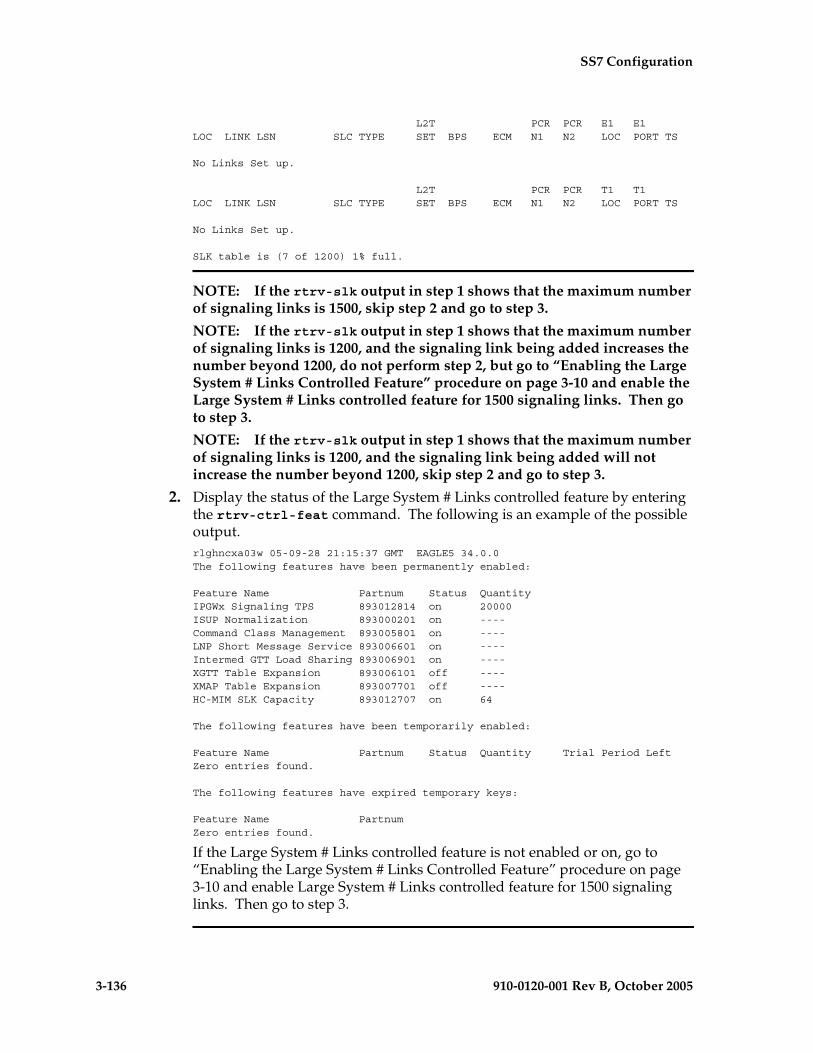
3-136 910-0120-001 Rev B, October 2005
SS7 Configuration
L2T PCR PCR E1 E1LOC LINK LSN SLC TYPE SET BPS ECM N1 N2 LOC PORT TS
No Links Set up.
L2T PCR PCR T1 T1LOC LINK LSN SLC TYPE SET BPS ECM N1 N2 LOC PORT TS
No Links Set up.
SLK table is (7 of 1200) 1% full.
NOTE: If the rtrv-slk output in step 1 shows that the maximum number of signaling links is 1500, skip step 2 and go to step 3.
NOTE: If the rtrv-slk output in step 1 shows that the maximum number of signaling links is 1200, and the signaling link being added increases the number beyond 1200, do not perform step 2, but go to “Enabling the Large System # Links Controlled Feature” procedure on page 3-10 and enable the Large System # Links controlled feature for 1500 signaling links. Then go to step 3.
NOTE: If the rtrv-slk output in step 1 shows that the maximum number of signaling links is 1200, and the signaling link being added will not increase the number beyond 1200, skip step 2 and go to step 3.
2. Display the status of the Large System # Links controlled feature by entering the rtrv-ctrl-feat command. The following is an example of the possible output.rlghncxa03w 05-09-28 21:15:37 GMT EAGLE5 34.0.0The following features have been permanently enabled:
Feature Name Partnum Status QuantityIPGWx Signaling TPS 893012814 on 20000ISUP Normalization 893000201 on ----Command Class Management 893005801 on ----LNP Short Message Service 893006601 on ----Intermed GTT Load Sharing 893006901 on ----XGTT Table Expansion 893006101 off ----XMAP Table Expansion 893007701 off ----HC-MIM SLK Capacity 893012707 on 64
The following features have been temporarily enabled:
Feature Name Partnum Status Quantity Trial Period LeftZero entries found.
The following features have expired temporary keys:
Feature Name PartnumZero entries found.
If the Large System # Links controlled feature is not enabled or on, go to “Enabling the Large System # Links Controlled Feature” procedure on page 3-10 and enable Large System # Links controlled feature for 1500 signaling links. Then go to step 3.

SS7 Configuration
910-0120-001 Rev B, October 2005 3-137
3. Display the cards in the database using the rtrv-card command. This is an example of the possible output.rlghncxa03w 05-09-28 09:12:36 GMT EAGLE5 34.0.0CARD TYPE APPL LSET NAME LINK SLC LSET NAME LINK SLC1101 TSM SCCP 1102 TSM GLS 1113 GSPM EOAM1114 TDM-A1115 GSPM EOAM1116 TDM-B1117 MDAL1201 LIMDS0 SS7ANSI lsa1 B 01202 LIMV35 SS7ANSI 1203 LIMDS0 SS7ANSI lsa2 B 01204 LIMDS0 SS7ANSI 1205 LIMV35 SS7ANSI lsa3 A 0 1206 LIMV35 SS7ANSI 1207 LIMDS0 SS7ANSI lsn1207a A 0 lsn1207b B 01208 LIMDS0 SS7ANSI 1212 LIMV35 SS7ANSI 1213 LIMDS0 SS7ANSI 1214 LIMV35 SS7ANSI lsn1214a A 0 lsa3 B 11215 LIMDS0 SS7ANSI 1301 LIMV35 ATMANSI 1302 LIMATM ATMANSI 1304 LIMV35 SS7ANSI 1305 LIMATM ATMANSI 1308 LIMV35 SS7ANSI 1311 LIMDS0 SS7ANSI 1313 LIMDS0 SS7ANSI 1315 LIMV35 CCS7ITU 1317 LIMV35 CCS7ITU 1318 LIMATM ATMANSI
If the required card is not in the database, go to the “Adding an SS7 LIM” procedure in the Database Administration Manual - System Management and add the card to the database.
4. Display the current linkset configuration using the rtrv-ls command. This is an example of the possible output.
rlghncxa03w 05-09-10 11:43:04 GMT EAGLE5 34.0.0
L3T SLT GWS GWS GWSLSN APCA (SS7) SCRN SET SET BEI LST LNKS ACT MES DIS SLSCI NISe1e2 001-207-000 none 1 1 no B 6 off off off no offls1305 000-005-000 none 1 1 no A 1 off off off no offls1307 000-007-000 none 1 1 no A 1 off off off no offe1m1s1 001-001-001 none 1 1 no A 7 off off off no offe1m1s2 001-001-002 none 1 1 no A 7 off off off no off
L3T SLT GWS GWS GWSLSN APCA (X25) SCRN SET SET BEI LST LNKS ACT MES DIS SLSCI NIS
L3T SLT GWS GWS GWSLSN APCI (SS7) SCRN SET SET BEI LST LNKS ACT MES DIS SLSCI NISe1e2i 1-207-0 none 1 1 no B 4 off off off --- onls1315 0-015-0 none 1 1 no A 1 off off off --- offls1317 0-017-0 none 1 1 no A 1 off off off --- one1m2s1 1-011-1 none 1 1 no A 7 off off off --- offe1m2s2 1-011-2 none 1 1 no A 7 off off off --- off

3-138 910-0120-001 Rev B, October 2005
SS7 Configuration
L3T SLT GWS GWS GWSLSN APCN (SS7) SCRN SET SET BEI LST LNKS ACT MES DIS SLSCI NIS
L3T SLT GWS GWS GWSLSN APCN24 (SS7) SCRN SET SET BEI LST LNKS ACT MES DIS SLSCI NIS
L3T SLT GWS GWS GWSLSN (CHINA) APCN (SS7) SCRN SET SET BEI LST LNKS ACT MES DIS SLSCI NIS
L3T SLT GWS GWS GWSLSN (CHINA) APCN24 (SS7) SCRN SET SET BEI LST LNKS ACT MES DIS SLSCI NIS
Link set table is (10 of 1024) 1% full.
If the required linkset is not in the database, go to the “Adding an SS7 Linkset” procedure on page 3-17 and add the linkset to the database.
5. Add the signaling link to the database using the ent-slk command. Use Table 3-10 on page 3-133 as a guide for the parameters that can be specified with the ent-slk command. For this example, enter these commands.
ent-slk:loc=1201:link=a:lsn=ls01:slc=0:l2tset=1
ent-slk:loc=1202:link=b:lsn=ls02:slc=0:l2tset=2:bps=64000
ent-slk:loc=1203:link=a:lsn=ls03:slc=0:l2tset=3
ent-slk:loc=1204:link=b:lsn=ls01:slc=1:l2tset=1
ent-slk:loc=1206:link=a:lsn=ls02:slc=1:l2tset=2:bps=64000
ent-slk:loc=1208:link=b:lsn=ls03:slc=1:l2tset=3
ent-slk:loc=1212:link=a:lsn=ls04:slc=1:l2tset=4:bps=64000
ent-slk:loc=1213:link=b:lsn=ls05:slc=0:l2tset=5
ent-slk:loc=1215:link=a:lsn=ls05:slc=1:l2tset=5
ent-slk:loc=1301:link=b:lsn=ls06:slc=0:l2tset=6:bps=56000
ent-slk:loc=1304:link=b:lsn=ls06:slc=1:l2tset=6:bps=56000
ent-slk:loc=1308:link=a:lsn=ls06:slc=2:l2tset=6:bps=56000
ent-slk:loc=1313:link=a:lsn=ls07:slc=0:l2tset=7
ent-slk:loc=1311:link=a:lsn=ls01:slc=2:l2tset=1
ent-slk:loc=1311:link=a1:lsn=ls05:slc=2:l2tset=5
ent-slk:loc=1311:link=b:lsn=ls03:slc=2:l2tset=3
ent-slk:loc=1311:link=b1:lsn=ls07:slc=1:l2tset=7
ent-slk:loc=1315:link=a:lsn=lsn5:slc=0:l2tset=11:bps=64000
ent-slk:loc=1317:link=a:lsn=lsi7:slc=0:l2tset=11:bps=64000
When each of these commands have successfully completed, this message should appear.
rlghncxa03w 05-09-07 08:29:03 GMT EAGLE5 34.0.0ENT-SLK: MASP A - COMPLTD

SS7 Configuration
910-0120-001 Rev B, October 2005 3-139
6. Verify the changes using the rtrv-slk command. This is an example of the possible output.rlghncxa03w 05-09-19 21:16:37 GMT EAGLE5 34.0.0 L2T L1 PCR PCRLOC LINK LSN SLC TYPE SET BPS MODE TSET ECM N1 N21201 A ls01 0 LIMDS0 1 56000 --- --- BASIC --- -----1201 B lsa1 0 LIMDS0 1 56000 --- --- BASIC --- -----1202 B ls02 0 LIMV35 2 64000 DTE --- BASIC --- -----1203 A ls03 0 LIMDS0 3 56000 --- --- BASIC --- -----1203 B lsa2 0 LIMDS0 1 56000 --- --- BASIC --- -----1204 B ls01 1 LIMDS0 1 56000 --- --- BASIC --- -----1205 A lsa3 0 LIMV35 4 64000 DCE ON BASIC --- -----1206 A ls02 1 LIMV35 2 64000 DTE --- BASIC --- -----1207 A lsn1207a 0 LIMDS0 1 56000 --- --- BASIC --- -----1207 B lsn1207b 0 LIMDS0 1 56000 --- --- BASIC --- -----1208 B ls03 1 LIMDS0 3 56000 --- --- BASIC --- -----1212 A ls04 0 LIMV35 4 64000 DTE --- BASIC --- -----1213 B ls05 0 LIMDS0 5 56000 --- --- BASIC --- -----1214 A lsn1214a 0 LIMV35 2 64000 DTE --- PCR 76 38001214 B lsa3 1 LIMV35 4 64000 DCE ON BASIC --- -----1215 A ls05 1 LIMDS0 5 56000 --- --- BASIC --- -----1301 B ls06 0 LIMV35 6 56000 DTE --- BASIC --- -----1304 B ls06 1 LIMV35 6 56000 DTE --- BASIC --- -----1308 A ls06 2 LIMV35 6 56000 DTE --- BASIC --- -----1311 A ls01 2 LIMDS0 1 56000 --- --- BASIC --- -----1311 A1 ls05 2 LIMDS0 5 56000 --- --- BASIC --- -----1311 B ls03 2 LIMDS0 3 56000 --- --- BASIC --- -----1311 B1 ls07 1 LIMDS0 7 56000 --- --- BASIC --- -----1313 A ls07 0 LIMDS0 7 56000 --- --- BASIC --- -----1315 A lsn5 0 LIMV35 11 64000 DTE OFF BASIC --- -----1317 A lsi7 0 LIMV35 11 64000 DTE OFF BASIC --- -----
LP ATMLOC LINK LSN SLC TYPE SET BPS TSEL VCI VPI LL
No Links Set up.
LP ATM E1ATMLOC LINK LSN SLC TYPE SET BPS TSEL VCI VPI CRC4 SI SN
No Links Set up.
LOC LINK LSN SLC TYPE IPLIML2
No Links Set up.
LOC LINK LSN SLC TYPE
No Links Set up.
L2T PCR PCR E1 E1LOC LINK LSN SLC TYPE SET BPS ECM N1 N2 LOC PORT TS
No Links Set up.
L2T PCR PCR T1 T1LOC LINK LSN SLC TYPE SET BPS ECM N1 N2 LOC PORT TS
No Links Set up.
SLK table is (31 of 1500) 3% full.

3-140 910-0120-001 Rev B, October 2005
SS7 Configuration
7. If any cards contain the first signaling link on a card, those cards must be brought into service with the rst-card command, specifying the location of the card. For this example, enter these commands.
rst-card:loc=1202
rst-card:loc=1204
rst-card:loc=1206
rst-card:loc=1208
rst-card:loc=1212
rst-card:loc=1213
rst-card:loc=1215
rst-card:loc=1301
rst-card:loc=1304
rst-card:loc=1308
rst-card:loc=1311
rst-card:loc=1313
rst-card:loc=1315
rst-card:loc=1317
When each of these commands have successfully completed, this message should appear.
rlghncxa03w 05-09-23 13:05:05 GMT EAGLE5 34.0.0Card has been allowed.
8. Activate all signaling links on the cards using the act-slk command, specifying the card location and signaling link specified in step 5. For this example, enter these commands.
act-slk:loc=1201:link=a
act-slk:loc=1201:link=b
act-slk:loc=1202:link=b
act-slk:loc=1203:link=a
act-slk:loc=1203:link=b
act-slk:loc=1204:link=b
act-slk:loc=1206:link=a
act-slk:loc=1208:link=b
act-slk:loc=1212:link=a
act-slk:loc=1213:link=b
act-slk:loc=1215:link=a
act-slk:loc=1301:link=b
act-slk:loc=1304:link=b
act-slk:loc=1308:link=a
act-slk:loc=1311:link=a
act-slk:loc=1311:link=a1
act-slk:loc=1311:link=b

SS7 Configuration
910-0120-001 Rev B, October 2005 3-141
act-slk:loc=1311:link=b1
act-slk:loc=1313:link=a
act-slk:loc=1315:link=a
act-slk:loc=1317:link=a
When each of these commands have successfully completed, this message should appear.rlghncxa03w 05-09-07 08:31:24 GMT EAGLE5 34.0.0Activate Link message sent to card
9. Check the status of the signaling links added in step 8 using the rept-stat-slk command. The state of each signaling link should be in service normal (IS-NR) after the link has completed alignment (shown in the PST field). This is an example of the possible output.
rlghncxa03w 05-09-19 21:16:37 GMT EAGLE5 34.0.0SLK LSN CLLI PST SST AST1201,A ls01 ls01clli IS-NR Avail ----1201,B lsa1 ----------- IS-NR Avail ----1202,B ls02 ls02clli IS-NR Avail ----1203,A ls03 ls03clli IS-NR Avail ----1203,B lsa2 ----------- IS-NR Avail ----1204,B ls01 ls01clli IS-NR Avail ----1205,A lsa3 ----------- IS-NR Avail ----1206,A ls02 ls02clli IS-NR Avail ----1207,A lsn1207a ----------- IS-NR Avail ----1207,B lsn1207b ----------- IS-NR Avail ----1208,B ls03 ls03clli IS-NR Avail ----1212,A ls04 ls04clli IS-NR Avail ----1213,B ls05 lsn5clli IS-NR Avail ----1214,A lsn1214a ----------- IS-NR Avail ----1214,B lsa3 ----------- IS-NR Avail ----1215,A ls05 lsn5clli IS-NR Avail ----1301,B ls06 ls06clli IS-NR Avail ----1304,B ls06 ls06clli IS-NR Avail ----1308,A ls06 ls06clli IS-NR Avail ----1311,A ls01 ls01clli IS-NR Avail ----1311,A1 ls05 lsn5clli IS-NR Avail ----1311,B ls03 ls03clli IS-NR Avail ----1311,B1 ls07 ls07clli IS-NR Avail ----1313,A ls07 ls07clli IS-NR Avail ----1315,A lsn5 ----------- IS-NR Avail ----1317,A lsi7 ----------- IS-NR Avail ----
10. Back up the new changes using the chg-db:action=backup:dest=fixed command. These messages should appear, the active Maintenance and Administration Subsystem Processor (MASP) appears first.
BACKUP (FIXED) : MASP A - Backup starts on active MASP.BACKUP (FIXED) : MASP A - Backup on active MASP to fixed disk complete.BACKUP (FIXED) : MASP A - Backup starts on standby MASP.BACKUP (FIXED) : MASP A - Backup on standby MASP to fixed disk complete.

3-142 910-0120-001 Rev B, October 2005
SS7 Configuration
Flowchart 3-6. Adding an SS7 Signaling Link (Sheet 1 of 3)
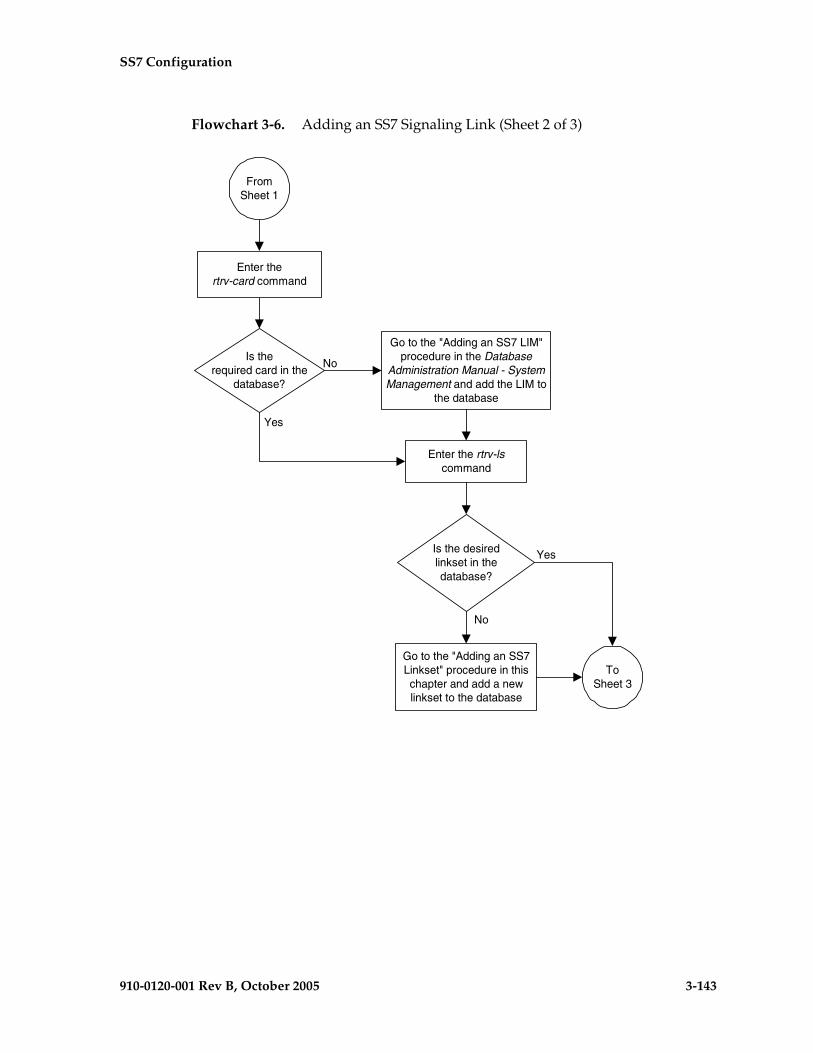
SS7 Configuration
910-0120-001 Rev B, October 2005 3-143
Flowchart 3-6. Adding an SS7 Signaling Link (Sheet 2 of 3)
Enter the rtrv-lscommand
Is the desiredlinkset in thedatabase?
Yes
No
ToSheet 3
FromSheet 1
Is therequired card in the
database?
Enter thertrv-card command
Go to the "Adding an SS7 LIM"procedure in the Database
Administration Manual - SystemManagement and add the LIM to
the database
Yes
No
Go to the "Adding an SS7Linkset" procedure in thischapter and add a newlinkset to the database
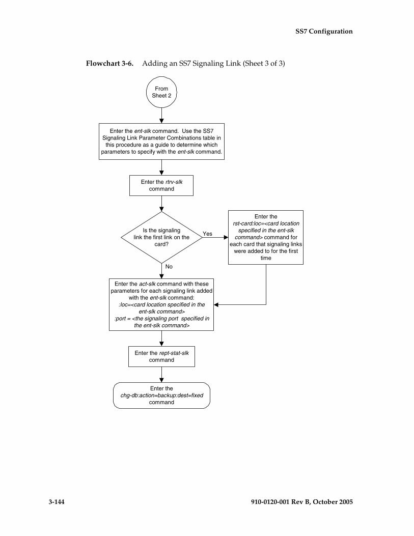
3-144 910-0120-001 Rev B, October 2005
SS7 Configuration
Flowchart 3-6. Adding an SS7 Signaling Link (Sheet 3 of 3)
Enter thechg-db:action=backup:dest=fixed
command
Enter the act-slk command with theseparameters for each signaling link added
with the ent-slk command::loc=<card location specified in the
ent-slk command>:port = <the signaling port specified in
the ent-slk command>
FromSheet 2
Is the signalinglink the first link on the
card?
Enter therst-card:loc=<card location
specified in the ent-slkcommand> command for
each card that signaling linkswere added to for the first
time
Enter the rept-stat-slkcommand
Enter the ent-slk command. Use the SS7Signaling Link Parameter Combinations table in
this procedure as a guide to determine whichparameters to specify with the ent-slk command.
Enter the rtrv-slkcommand
Yes
No

SS7 Configuration
910-0120-001 Rev B, October 2005 3-145
Removing an SS7 Signaling Link
This procedure is used to remove an SS7 low-speed, ATM, E1, E1 high-speed, or T1 signaling link from the database using the dlt-slk command. To remove other types of signaling links from the database, go to one of these procedures:
• An IP signaling link, go to the “Removing an IP Signaling Link” procedure in the Database Administration Manual – IP7 Secure Gateway.
• An X.25 signaling link, go to the “Removing an X.25 Signaling Link” procedure in the Database Administration Manual – Features.
The link to be removed must exist in the database. This can be verified in step 1.
The dlt-slk command uses these parameters.
:loc – The card location of the LIM that the SS7 signaling link is assigned to.
:link – The signaling link on the card specified in the loc parameter.
:force – This parameter must be used to remove the last link in a linkset without having to remove all of the routes that referenced the linkset.
The tfatcabmlq parameter (TFA/TCA Broadcast Minimum Link Quantity), assigned to linksets, shows the minimum number of links in the given linkset (or in the combined link set in which it resides) that must be available for traffic. When the number of signaling links in the specified linkset is equal to or greater than the value of the tfatcabmlq parameter, the status of the routes that use the specified linkset is set to allowed and can carry traffic. Otherwise, these routes are restricted. The value of the tfatcabmlq parameter cannot exceed the total number of signaling links contained in the linkset.
The dlt-slk command makes sure that the number of signaling links assigned to a linkset is greater than or equal to the value of the tfatcabmlq parameter. If the number of signaling links associated with a linkset drops below the value of the tfatcabmlq parameter for that linkset, the tfatcabmlq value for that linkset is automatically decremented. The value of the tfatcabmlq parameter for a specified linkset can be verified using the rtrv-ls:lsn=<linkset name> command specifying the name of the linkset. The tfatcabmlq parameter value is shown in the tfatcabmlq field of the rtrv-ls command output.
The signaling link cannot be removed from the database if link fault sectionalization (LFS) tests are being performed on it. This can be verified using the rept-stat-lfs command.

3-146 910-0120-001 Rev B, October 2005
SS7 Configuration
Canceling the RTRV-SLK Command
Because the rtrv-slk command used in this procedure can output information for a long period of time, the rtrv-slk command can be canceled and the output to the terminal stopped. There are three ways that the rtrv-slk command can be canceled.
• Press the F9 function key on the keyboard at the terminal where the rtrv-slk command was entered.
• Enter the canc-cmd without the trm parameter at the terminal where the rtrv-slk command was entered.
• Enter the canc-cmd:trm=<xx>, where <xx> is the terminal where the rtrv-slk command was entered, from another terminal other that the terminal where the rtrv-slk command was entered. To enter the canc-cmd:trm=<xx> command, the terminal must allow Security Administration commands to be entered from it and the user must be allowed to enter Security Administration commands. The terminal’s permissions can be verified with the rtrv-secu-trm command. The user’s permissions can be verified with the rtrv-user or rtrv-secu-user commands.
For more information about the canc-cmd command, go to the Commands Manual.
Procedure
1. Display the current link configuration using the rtrv-slk command. This is an example of the possible output.
rlghncxa03w 05-09-19 21:16:37 GMT EAGLE5 34.0.0 L2T L1 PCR PCRLOC LINK LSN SLC TYPE SET BPS MODE TSET ECM N1 N21201 A ls01 0 LIMDS0 1 56000 --- --- BASIC --- -----1201 B lsa1 0 LIMDS0 1 56000 --- --- BASIC --- -----1202 B ls02 0 LIMV35 2 64000 DTE --- BASIC --- -----1203 A ls03 0 LIMDS0 3 56000 --- --- BASIC --- -----1203 B lsa2 0 LIMDS0 1 56000 --- --- BASIC --- -----1204 B ls01 1 LIMDS0 1 56000 --- --- BASIC --- -----1205 A lsa3 0 LIMV35 4 64000 DCE ON BASIC --- -----1206 A ls02 1 LIMV35 2 64000 DTE --- BASIC --- -----1207 A lsn1207a 0 LIMDS0 1 56000 --- --- BASIC --- -----1207 B lsn1207b 0 LIMDS0 1 56000 --- --- BASIC --- -----1208 B ls03 1 LIMDS0 3 56000 --- --- BASIC --- -----1212 A ls04 0 LIMV35 4 64000 DTE --- BASIC --- -----1213 B ls05 0 LIMDS0 5 56000 --- --- BASIC --- -----1214 A lsn1214a 0 LIMV35 2 64000 DTE --- PCR 76 38001214 B lsa3 1 LIMV35 4 64000 DCE ON BASIC --- -----1215 A ls05 1 LIMDS0 5 56000 --- --- BASIC --- -----1301 B ls06 0 LIMV35 6 56000 DTE --- BASIC --- -----1304 B ls06 1 LIMV35 6 56000 DTE --- BASIC --- -----1308 A ls06 2 LIMV35 6 56000 DTE --- BASIC --- -----1311 A ls01 2 LIMDS0 1 56000 --- --- BASIC --- -----1311 A1 ls05 2 LIMDS0 5 56000 --- --- BASIC --- -----1311 B ls03 2 LIMDS0 3 56000 --- --- BASIC --- -----1311 B1 ls07 1 LIMDS0 7 56000 --- --- BASIC --- -----1313 A ls07 0 LIMDS0 7 56000 --- --- BASIC --- -----

SS7 Configuration
910-0120-001 Rev B, October 2005 3-147
1315 A lsn5 0 LIMV35 11 64000 DTE OFF BASIC --- -----1317 A lsi7 0 LIMV35 11 64000 DTE OFF BASIC --- -----
LP ATMLOC LINK LSN SLC TYPE SET BPS TSEL VCI VPI LL1302 A atmansi0 0 LIMATM 3 1544000 EXTERNAL 35 15 01305 A atmansi1 0 LIMATM 4 1544000 INTERNAL 100 20 21318 A atmansi0 1 LIMATM 9 1544000 LINE 150 25 4
LP ATM E1ATMLOC LINK LSN SLC TYPE SET BPS TSEL VCI VPI CRC4 SI SN2101 A atmitu1 0 LIME1ATM 5 2.048M LINE 150 2 ON 1 202105 A atmitu1 1 LIME1ATM 5 2.048M LINE 35 15 ON 2 15
LOC LINK LSN SLC TYPE IPLIML2
No Links Set Up.
LOC LINK LSN SLC TYPE
No Links Set Up.
L2T PCR PCR E1 E1LOC LINK LSN SLC TYPE SET BPS ECM N1 N2 LOC PORT TS
No Links Set Up.
L2T PCR PCR T1 T1LOC LINK LSN SLC TYPE SET BPS ECM N1 N2 LOC PORT TS
No Links Set Up.
SLK table is (31 of 1200) 3% full
2. Enter the rept-stat-lfs command to verify whether or not a link fault sectionalization test is being performed on the signaling link to be removed from the database. This is an example of the possible output.
rlghncxa03w 05-09-07 08:41:12 GMT EAGLE5 34.0.0SLK LBP PATTERN MAX-ERRORS BIT_ERRORS MAX-TIME TEST-TIME1201,A 5 B0247 56 30 01:00:00 00:00:501202,A 3 B511 56 27 01:00:00 00:01:051203,A 1 OCTET 56 12 01:00:00 00:02:071204,A 6 ALTERNATE 56 28 01:00:00 00:04:081205,A 2 B0247 56 36 01:00:00 00:03:051206,A 1 B0247 56 15 01:00:00 00:06:061207,A 3 B0247 56 19 01:00:00 00:02:041208,A 5 B0247 56 23 01:00:00 00:04:011208,B1 4 B0247 56 23 01:00:00 00:08:01
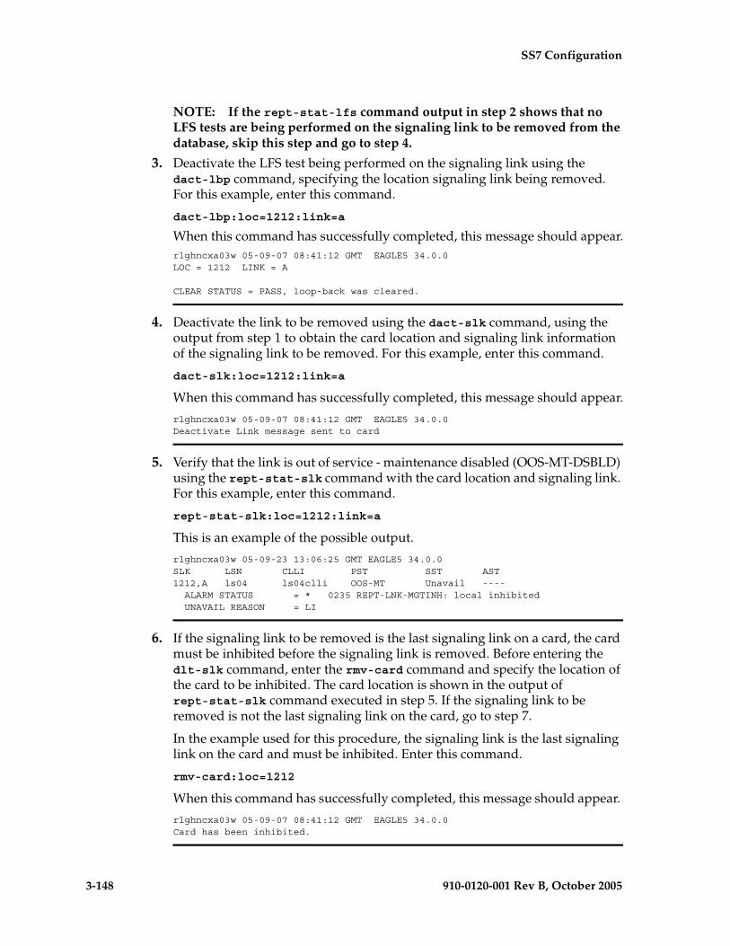
3-148 910-0120-001 Rev B, October 2005
SS7 Configuration
NOTE: If the rept-stat-lfs command output in step 2 shows that no LFS tests are being performed on the signaling link to be removed from the database, skip this step and go to step 4.
3. Deactivate the LFS test being performed on the signaling link using the dact-lbp command, specifying the location signaling link being removed. For this example, enter this command.
dact-lbp:loc=1212:link=a
When this command has successfully completed, this message should appear.rlghncxa03w 05-09-07 08:41:12 GMT EAGLE5 34.0.0LOC = 1212 LINK = A
CLEAR STATUS = PASS, loop-back was cleared.
4. Deactivate the link to be removed using the dact-slk command, using the output from step 1 to obtain the card location and signaling link information of the signaling link to be removed. For this example, enter this command.
dact-slk:loc=1212:link=a
When this command has successfully completed, this message should appear.
rlghncxa03w 05-09-07 08:41:12 GMT EAGLE5 34.0.0Deactivate Link message sent to card
5. Verify that the link is out of service - maintenance disabled (OOS-MT-DSBLD) using the rept-stat-slk command with the card location and signaling link. For this example, enter this command.
rept-stat-slk:loc=1212:link=a
This is an example of the possible output.
rlghncxa03w 05-09-23 13:06:25 GMT EAGLE5 34.0.0SLK LSN CLLI PST SST AST1212,A ls04 ls04clli OOS-MT Unavail ---- ALARM STATUS = * 0235 REPT-LNK-MGTINH: local inhibited UNAVAIL REASON = LI
6. If the signaling link to be removed is the last signaling link on a card, the card must be inhibited before the signaling link is removed. Before entering the dlt-slk command, enter the rmv-card command and specify the location of the card to be inhibited. The card location is shown in the output of rept-stat-slk command executed in step 5. If the signaling link to be removed is not the last signaling link on the card, go to step 7.
In the example used for this procedure, the signaling link is the last signaling link on the card and must be inhibited. Enter this command.
rmv-card:loc=1212
When this command has successfully completed, this message should appear.
rlghncxa03w 05-09-07 08:41:12 GMT EAGLE5 34.0.0Card has been inhibited.

SS7 Configuration
910-0120-001 Rev B, October 2005 3-149
7. Remove the signaling link from the EAGLE 5 SAS using the dlt-slk command. If there is only one signaling link in the linkset, the force=yes parameter must be specified to remove the signaling link.
In the example used in this procedure, the signaling link is the last signaling link in the linkset. Enter this command.
dlt-slk:loc=1212:link=a:force=yes
When this command has successfully completed, this message should appear.
rlghncxa03w 05-09-07 08:41:17 GMT EAGLE5 34.0.0DLT-SLK: MASP A - COMPLTD
8. Verify the changes using the rtrv-slk command. This is an example of the possible output.
rlghncxa03w 05-09-19 21:16:37 GMT EAGLE5 34.0.0 L2T L1 PCR PCRLOC LINK LSN SLC TYPE SET BPS MODE TSET ECM N1 N21201 A ls01 0 LIMDS0 1 56000 --- --- BASIC --- -----1201 B lsa1 0 LIMDS0 1 56000 --- --- BASIC --- -----1202 B ls02 0 LIMV35 2 64000 DTE --- BASIC --- -----1203 A ls03 0 LIMDS0 3 56000 --- --- BASIC --- -----1203 B lsa2 0 LIMDS0 1 56000 --- --- BASIC --- -----1204 B ls01 1 LIMDS0 1 56000 --- --- BASIC --- -----1205 A lsa3 0 LIMV35 4 64000 DCE ON BASIC --- -----1206 A ls02 1 LIMV35 2 64000 DTE --- BASIC --- -----1207 A lsn1207a 0 LIMDS0 1 56000 --- --- BASIC --- -----1207 B lsn1207b 0 LIMDS0 1 56000 --- --- BASIC --- -----1208 B ls03 1 LIMDS0 3 56000 --- --- BASIC --- -----1213 B ls05 0 LIMDS0 5 56000 --- --- BASIC --- -----1214 A lsn1214a 0 LIMV35 2 64000 DTE --- PCR 76 38001214 B lsa3 1 LIMV35 4 64000 DCE ON BASIC --- -----1215 A ls05 1 LIMDS0 5 56000 --- --- BASIC --- -----1301 B ls06 0 LIMV35 6 56000 DTE --- BASIC --- -----1304 B ls06 1 LIMV35 6 56000 DTE --- BASIC --- -----1308 A ls06 2 LIMV35 6 56000 DTE --- BASIC --- -----1311 A ls01 2 LIMDS0 1 56000 --- --- BASIC --- -----1311 A1 ls05 2 LIMDS0 5 56000 --- --- BASIC --- -----1311 B ls03 2 LIMDS0 3 56000 --- --- BASIC --- -----1311 B1 ls07 1 LIMDS0 7 56000 --- --- BASIC --- -----1313 A ls07 0 LIMDS0 7 56000 --- --- BASIC --- -----1315 A lsn5 0 LIMV35 11 64000 DTE OFF BASIC --- -----1317 A lsi7 0 LIMV35 11 64000 DTE OFF BASIC --- -----
LP ATMLOC LINK LSN SLC TYPE SET BPS TSEL VCI VPI LL1302 A atmansi0 0 LIMATM 3 1544000 EXTERNAL 35 15 01305 A atmansi1 0 LIMATM 4 1544000 INTERNAL 100 20 21318 A atmansi0 1 LIMATM 9 1544000 LINE 150 25 4
LP ATM E1ATMLOC LINK LSN SLC TYPE SET BPS TSEL VCI VPI CRC4 SI SN2101 A atmitu1 0 LIME1ATM 5 2.048M LINE 150 2 ON 1 202105 A atmitu1 1 LIME1ATM 5 2.048M LINE 35 15 ON 2 15
LOC LINK LSN SLC TYPE IPLIML2
No Links Set up.
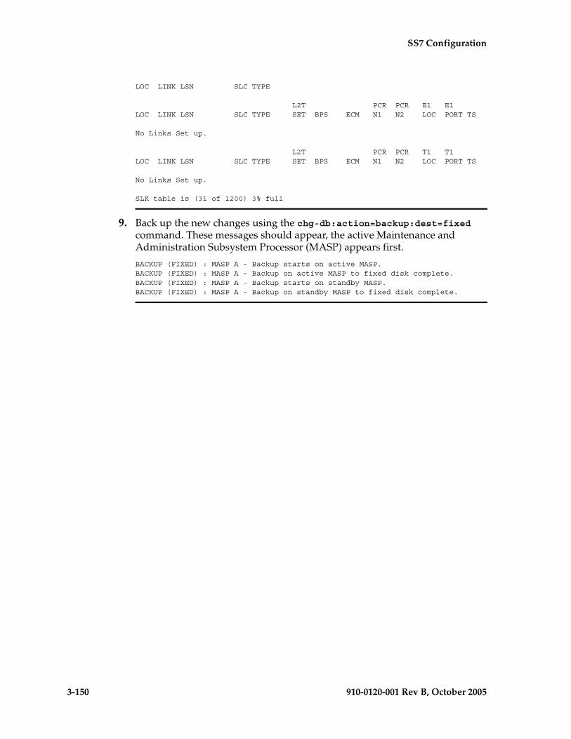
3-150 910-0120-001 Rev B, October 2005
SS7 Configuration
LOC LINK LSN SLC TYPE
L2T PCR PCR E1 E1LOC LINK LSN SLC TYPE SET BPS ECM N1 N2 LOC PORT TS
No Links Set up.
L2T PCR PCR T1 T1LOC LINK LSN SLC TYPE SET BPS ECM N1 N2 LOC PORT TS
No Links Set up.
SLK table is (31 of 1200) 3% full
9. Back up the new changes using the chg-db:action=backup:dest=fixed command. These messages should appear, the active Maintenance and Administration Subsystem Processor (MASP) appears first.
BACKUP (FIXED) : MASP A - Backup starts on active MASP.BACKUP (FIXED) : MASP A - Backup on active MASP to fixed disk complete.BACKUP (FIXED) : MASP A - Backup starts on standby MASP.BACKUP (FIXED) : MASP A - Backup on standby MASP to fixed disk complete.

SS7 Configuration
910-0120-001 Rev B, October 2005 3-151
Flowchart 3-7. Removing an SS7 Signaling Link (Sheet 1 of 2)
Is a link faultsectionalization (LFS) test
being performed in the signalinglink to be removed from the
database?
Yes
No
Enter thertrv-slk command
ToSheet 2
Enter therept-stat-lfs command
Enter the dact-lbp command withthese parameters:
:loc=<location of the signaling link>:port=<signaling link port>
Enter the dact-slk command withthese parameters:
:loc=<location of the signaling link>:port=<signaling link port>
Enter the rept-stat-slk commandwith these parameters:
:loc=<location of the signaling link>:port=<signaling link port>
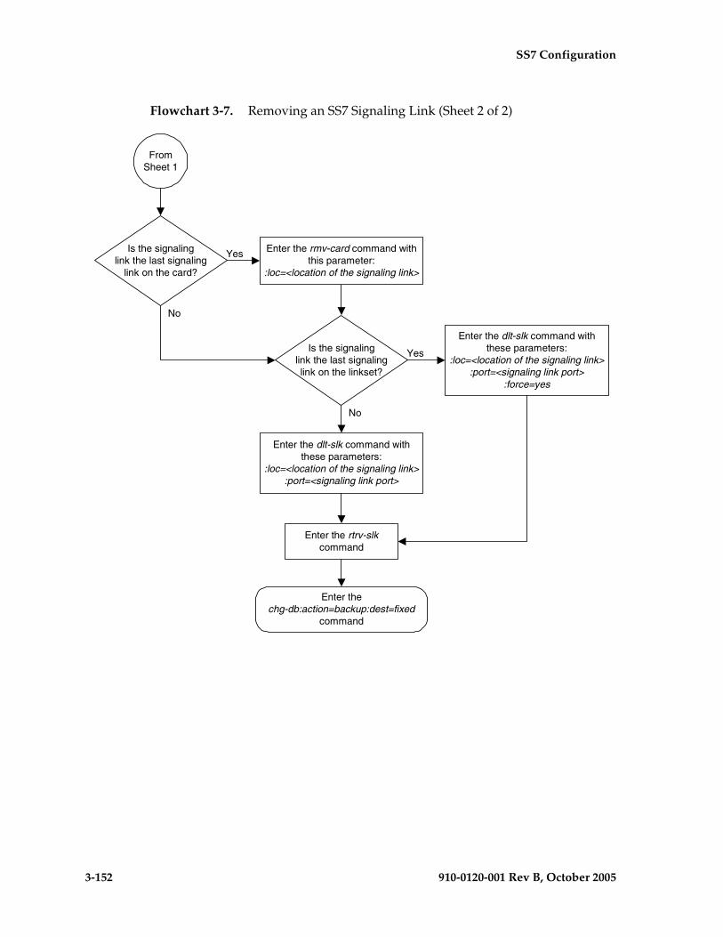
3-152 910-0120-001 Rev B, October 2005
SS7 Configuration
Flowchart 3-7. Removing an SS7 Signaling Link (Sheet 2 of 2)
Enter thechg-db:action=backup:dest=fixed
command
FromSheet 1
Enter the rtrv-slkcommand
Is the signalinglink the last signaling
link on the card?
Yes
No
Enter the rmv-card command withthis parameter:
:loc=<location of the signaling link>
Is the signalinglink the last signalinglink on the linkset?
Enter the dlt-slk command withthese parameters:
:loc=<location of the signaling link>:port=<signaling link port>
:force=yes
Enter the dlt-slk command withthese parameters:
:loc=<location of the signaling link>:port=<signaling link port>
No
Yes

SS7 Configuration
910-0120-001 Rev B, October 2005 3-153
Adding a Route Containing an SS7 DPC
This procedure is used to add a route containing an SS7 DPC to the database using the ent-rte command. The routes configured in this procedure do not contain cluster point codes or X.25 point codes as DPCs, or IPGWx linksets. These routes are configured in these procedures:
• “Adding a Route Containing a Cluster Point Code” on page 3-164
• “Adding a Route Containing an IPGWx Linkset” on page 3-172
• “Adding a Route Containing an X.25 DPC” on page 3-181.
The ent-rte command uses these parameters.
:dpc/dpca/dpci/dpcn/dpcn24 – The destination point code of the node that the traffic is bound for.
NOTE: See “Point Code Formats” on page 2-4 for a definition of the point code types that are used on the EAGLE 5 SAS and for a definition of the different formats that can be used for ITU national point codes.
:lsn – The name of the linkset that will carry the traffic bound for the node specified by the destination point code.
:rc – The relative cost (priority) for this route.
:force – This parameter allows a route to be added to the database even if the linkset to be assigned to the route does not have any signaling links in it.
These items must be configured in the database before a route can be added in this procedure:
• Destination point code (DPC) – see one of these procedures depending on the type of point code required:
– For a Network Routing DPC – “Adding a Network Routing Point Code” on page 2-181.
– For all other DPCs – “Adding a Destination Point Code” on page 2-191
• Linkset – see “Adding an SS7 Linkset” on page 3-17
• Link – see “Adding an SS7 Signaling Link” on page 3-130
The linkset assigned to this route must have an adjacent point code (APC) in the SS7 domain. The domain of the DPC is shown in the DOMAIN field in the output of the rtrv-dstn command.

3-154 910-0120-001 Rev B, October 2005
SS7 Configuration
The DPC of the route must be of the same format as the APC of the linkset being added to the route. That is, routes containing ANSI DPCs must have linksets with ANSI APCs; routes containing ITU-I DPCs must have linksets with ITU-I APCs; routes containing 14-bit ITU-N DPCs must have linksets with 14-bit ITU-N APCs; routes containing 24-bit ITU-N DPCs must have linksets with 24-bit ITU-N APCs. The DPC of the route must be defined as a true point code in the rtrv-dstn output. Alias point codes and secondary point codes cannot be used. True point codes are shown in the output of the rtrv-dstn command in the DPCA, DPCI, DPCN, or DPCN24 fields. Private point codes cannot be used as the DPC of a route in this procedure. Routes that have private point codes as the DPC of a route can contain only IPGWx linksets. Perform the “Adding a Route Containing an IPGWx Linkset” on page 3-172 to add routes containing IPGWx linksets.
The DPC of the route is the destination point code to be reached by the route and is shown in the output of the rtrv-rte command in the DPCA, DPCI, DPCN, or DPCN24 fields.
The APCA, APCI, APCN, and APCN24 fields in the output of the rtrv-rte command show the point code of the node that is directly adjacent to the node in the route.
A linkset can only be entered once as a route for each DPC.
A maximum of six routes can be defined for each DPC.
A maximum of two linksets can be assigned the same cost. The cost of the route is defined by the rc parameter of the ent-rte command and is shown in the RC field in the output of the rtrv-rte command.
The force=yes parameter must be specified if the specified linkset has no signaling links assigned to it. Otherwise, each linkset must have at least one signaling link assigned to it.
The ANSI DPC (DPC/DPCA) of the route can use either a full point code or a network routing point code. ITU DPCs (DPCI, DPCN, and DPCN24) must use full point codes. For more information on network routing point codes, go to the “Network Routing” section on page 2-174.
If the DPC of the route is a member of a cluster point code, and the nested cluster allowed indicator (ncai parameter of either the ent-dstn or chg-dstn command) is set to no, then the route to the DPC must be the same as the route to the cluster point code. If the nested cluster allowed indicator is set to yes, the route to the member of the cluster does not have to be the same as the route to the cluster point code. For more information, see the “Nested Cluster Routing” section on page 2-135.
For routes containing 14-bit ITU National DPCs with group codes, if the linkset assigned to the route has the MULTGC value set to yes, then 14-bit ITU National DPCs with group codes that are different from the linkset APC group code can be assigned to the route. If the MULTGC value is set to no, then only 14-bit ITU National DPCs with group codes that are the same as the linkset APC group code can be assigned to the route.
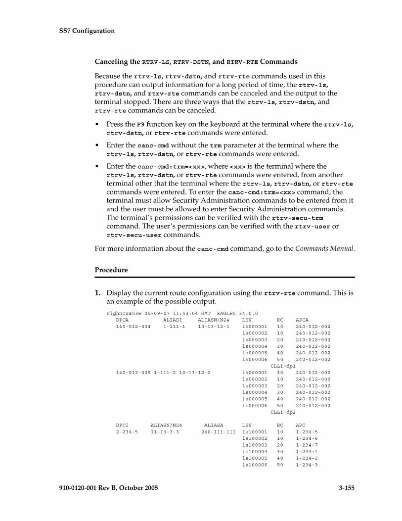
SS7 Configuration
910-0120-001 Rev B, October 2005 3-155
Canceling the RTRV-LS, RTRV-DSTN, and RTRV-RTE Commands
Because the rtrv-ls, rtrv-dstn, and rtrv-rte commands used in this procedure can output information for a long period of time, the rtrv-ls, rtrv-dstn, and rtrv-rte commands can be canceled and the output to the terminal stopped. There are three ways that the rtrv-ls, rtrv-dstn, and rtrv-rte commands can be canceled.
• Press the F9 function key on the keyboard at the terminal where the rtrv-ls, rtrv-dstn, or rtrv-rte commands were entered.
• Enter the canc-cmd without the trm parameter at the terminal where the rtrv-ls, rtrv-dstn, or rtrv-rte commands were entered.
• Enter the canc-cmd:trm=<xx>, where <xx> is the terminal where the rtrv-ls, rtrv-dstn, or rtrv-rte commands were entered, from another terminal other that the terminal where the rtrv-ls, rtrv-dstn, or rtrv-rte commands were entered. To enter the canc-cmd:trm=<xx> command, the terminal must allow Security Administration commands to be entered from it and the user must be allowed to enter Security Administration commands. The terminal’s permissions can be verified with the rtrv-secu-trm command. The user’s permissions can be verified with the rtrv-user or rtrv-secu-user commands.
For more information about the canc-cmd command, go to the Commands Manual.
Procedure
1. Display the current route configuration using the rtrv-rte command. This is an example of the possible output.
rlghncxa03w 05-09-07 11:43:04 GMT EAGLE5 34.0.0 DPCA ALIASI ALIASN/N24 LSN RC APCA 140-012-004 1-111-1 10-13-12-1 ls000001 10 240-012-002 ls000002 10 240-012-002 ls000003 20 240-012-002 ls000004 30 240-012-002 ls000005 40 240-012-002 ls000006 50 240-012-002 CLLI=dp1 140-012-005 1-111-2 10-13-12-2 ls000001 10 240-012-002 ls000002 10 240-012-002 ls000003 20 240-012-002 ls000004 30 240-012-002 ls000005 40 240-012-002 ls000006 50 240-012-002 CLLI=dp2
DPCI ALIASN/N24 ALIASA LSN RC APC 2-234-5 11-13-3-3 240-111-111 ls100001 10 1-234-5 ls100002 10 1-234-6 ls100003 20 1-234-7 ls100004 30 1-234-1 ls100005 40 1-234-2 ls100006 50 1-234-3

3-156 910-0120-001 Rev B, October 2005
SS7 Configuration
CLLI=idp1
DPCN ALIASA ALIASI LSN RC APC 12-12-13-3 011-222-111 0-001-1 ls200001 10 10-13-9-3 ls200002 10 10-13-10-0 ls200003 20 10-13-10-1 ls200004 30 10-13-10-2 ls200005 40 10-13-10-3 ls200006 50 10-13-11-0 CLLI=ndp1
DPCN24 ALIASA ALIASI LSN RC APC
2. Verify that the destination point code of the route is in the destination point code table by using the rtrv-dstn command. This is an example of the possible output.
rlghncxa03w 05-09-10 11:43:04 GMT EAGLE5 34.0.0 DPCA CLLI BEI ELEI ALIASI ALIASN/N24 DOMAIN 001-002-003 ls04clli yes --- ---------- -------------- SS7 001-002-003 ls04clli yes --- ---------- -------------- SS7 002-002-100 ls01clli no --- ---------- -------------- SS7 002-007-008 ls06clli yes --- ---------- -------------- SS7 002-009-003 -------- no --- ---------- -------------- SS7 002-250-010 -------- no --- ---------- -------------- SS7 003-003-003 ls03clli yes --- ---------- -------------- SS7 003-020-100 -------- no --- ---------- -------------- SS7 004-004-004 ls02clli yes --- ---------- -------------- SS7 004-030-200 -------- no --- ---------- -------------- SS7 009-002-003 -------- no --- ---------- -------------- SS7 179-100-087 -------- yes --- ---------- -------------- SS7 200-050-176 -------- yes --- ---------- -------------- SS7 240-007-000 -------- yes --- ---------- -------------- SS7 240-012-004 rlghncbb001 yes --- 1-111-1 11111 SS7 240-012-005 rlghncbb002 yes --- 1-112-2 11112 SS7 240-012-006 rlghncbb003 yes --- 1-112-3 11113 SS7 240-012-008 -------- yes --- 1-113-5 11114 SS7 244-010-004 ls06clli no --- ---------- -------------- X25 244-012-005 ls07clli no --- ---------- -------------- X25 244-012-006 ls08clli no --- ---------- -------------- X25 244-012-007 -------- no --- ---------- -------------- X25 244-012-008 -------- no --- ---------- -------------- X25
DPCI CLLI BEI ELEI ALIASA ALIASN/N24 DOMAIN 2-131-1 rlghncbb023 no --- 222-210-000 12001 SS7 2-131-2 -------- no --- 222-211-001 12002 SS7 2-131-3 -------- no --- 222-211-002 12003 SS7 3-150-4 lsi7clli yes --- -------------- -------------- SS7
DPCN CLLI BEI ELEI ALIASA ALIASI DOMAIN 10685 lsn5clli yes --- -------------- ---------- SS7 11211 rlghncbb013 no --- 222-200-200 2-121-1 SS7 11212 rlghncbb013 no --- 222-200-201 2-121-2 SS7
DPCN24 CLLI BEI ELEI ALIASA ALIASI DOMAIN
Destination table is (29 of 2000) 1% full
If the destination point code of the route being added in this procedure is not shown in the rtrv-rte and rtrv-dstn outputs, go to one of these procedures
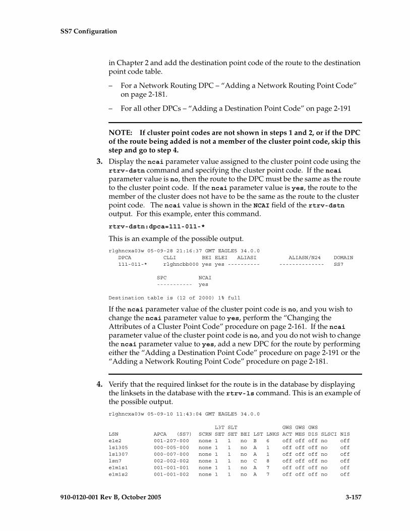
SS7 Configuration
910-0120-001 Rev B, October 2005 3-157
in Chapter 2 and add the destination point code of the route to the destination point code table.
– For a Network Routing DPC – “Adding a Network Routing Point Code” on page 2-181.
– For all other DPCs – “Adding a Destination Point Code” on page 2-191
NOTE: If cluster point codes are not shown in steps 1 and 2, or if the DPC of the route being added is not a member of the cluster point code, skip this step and go to step 4.
3. Display the ncai parameter value assigned to the cluster point code using the rtrv-dstn command and specifying the cluster point code. If the ncai parameter value is no, then the route to the DPC must be the same as the route to the cluster point code. If the ncai parameter value is yes, the route to the member of the cluster does not have to be the same as the route to the cluster point code. The ncai value is shown in the NCAI field of the rtrv-dstn output. For this example, enter this command.
rtrv-dstn:dpca=111-011-*
This is an example of the possible output.
rlghncxa03w 05-09-28 21:16:37 GMT EAGLE5 34.0.0 DPCA CLLI BEI ELEI ALIASI ALIASN/N24 DOMAIN 111-011-* rlghncbb000 yes yes ---------- -------------- SS7
SPC NCAI ----------- yes
Destination table is (12 of 2000) 1% full
If the ncai parameter value of the cluster point code is no, and you wish to change the ncai parameter value to yes, perform the “Changing the Attributes of a Cluster Point Code” procedure on page 2-161. If the ncai parameter value of the cluster point code is no, and you do not wish to change the ncai parameter value to yes, add a new DPC for the route by performing either the “Adding a Destination Point Code” procedure on page 2-191 or the “Adding a Network Routing Point Code” procedure on page 2-181.
4. Verify that the required linkset for the route is in the database by displaying the linksets in the database with the rtrv-ls command. This is an example of the possible output.
rlghncxa03w 05-09-10 11:43:04 GMT EAGLE5 34.0.0
L3T SLT GWS GWS GWSLSN APCA (SS7) SCRN SET SET BEI LST LNKS ACT MES DIS SLSCI NISe1e2 001-207-000 none 1 1 no B 6 off off off no offls1305 000-005-000 none 1 1 no A 1 off off off no offls1307 000-007-000 none 1 1 no A 1 off off off no offlsn7 002-002-002 none 1 1 no C 8 off off off no offe1m1s1 001-001-001 none 1 1 no A 7 off off off no offe1m1s2 001-001-002 none 1 1 no A 7 off off off no off

3-158 910-0120-001 Rev B, October 2005
SS7 Configuration
L3T SLT GWS GWS GWSLSN APCA (X25) SCRN SET SET BEI LST LNKS ACT MES DIS SLSCI NIS
L3T SLT GWS GWS GWSLSN APCI (SS7) SCRN SET SET BEI LST LNKS ACT MES DIS SLSCI NISe1e2i 1-207-0 none 1 1 no B 4 off off off --- onls1315 0-015-0 none 1 1 no A 1 off off off --- offls1317 0-017-0 none 1 1 no A 1 off off off --- onls7890 7-089-0 none 1 2 no B 1 off off off --- offe1m2s1 1-011-1 none 1 1 no A 7 off off off --- offe1m2s2 1-011-2 none 1 1 no A 7 off off off --- off
L3T SLT GWS GWS GWSLSN APCN (SS7) SCRN SET SET BEI LST LNKS ACT MES DIS SLSCI NIS
L3T SLT GWS GWS GWSLSN APCN24 (SS7) SCRN SET SET BEI LST LNKS ACT MES DIS SLSCI NIS
L3T SLT GWS GWS GWSLSN (CHINA) APCN (SS7) SCRN SET SET BEI LST LNKS ACT MES DIS SLSCI NIS
L3T SLT GWS GWS GWSLSN (CHINA) APCN24 (SS7) SCRN SET SET BEI LST LNKS ACT MES DIS SLSCI NIS
Link set table is (12 of 1024) 1% full.
If the required linkset is not in the database, perform the “Adding an SS7 Linkset” procedure on page 3-17 and add the linkset to the database with the ipgwapc=no parameter value. The APC of the linkset cannot be a private point code. Skip step 5 and go to step 6.
5. Display each linkset being assigned to the route to verify the multgc and ipgwapc parameter values with the rtrv-ls command, specifying the name of the linkset that will be assigned to the route.
If the multgc linkset parameter value is yes, then 14-bit ITU National DPCs with group codes that are different from the linkset APC group code can be assigned to the route. If the multgc value is set to no, then only 14-bit ITU National DPCs with group codes that are the same as the linkset APC group code can be assigned to the route. The multgc value is shown in the MULTGC field of the rtrv-ls output.
Linksets that have the ipgwapc=yes parameter value are assigned to routes using the “Adding a Route Containing an IPGWx Linkset” procedure on page 3-172. If the linkset displayed in this step contains the ipgwapc=yes parameter, repeat this step with another linkset shown in step 4. If all the linksets have been displayed, and the ipgwapc value for all the linksets is yes, add the desired linkset by performing the “Adding an SS7 Linkset” procedure on page 3-17 with the ipgwapc=no parameter value. The APC of the linkset cannot be a private point code.
For this example, enter the following commands.
rtrv-ls:lsn=lsn7
This is an example of the possible output.
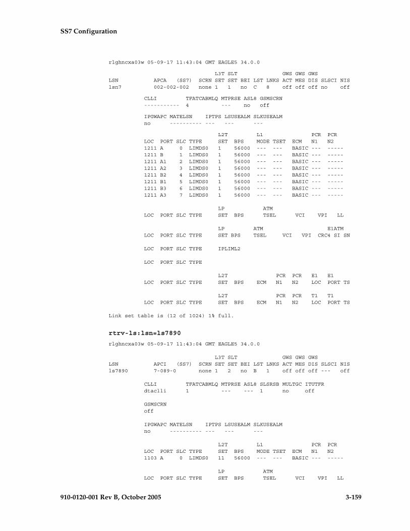
SS7 Configuration
910-0120-001 Rev B, October 2005 3-159
rlghncxa03w 05-09-17 11:43:04 GMT EAGLE5 34.0.0
L3T SLT GWS GWS GWSLSN APCA (SS7) SCRN SET SET BEI LST LNKS ACT MES DIS SLSCI NISlsn7 002-002-002 none 1 1 no C 8 off off off no off
CLLI TFATCABMLQ MTPRSE ASL8 GSMSCRN ----------- 4 --- no off
IPGWAPC MATELSN IPTPS LSUSEALM SLKUSEALM no ---------- --- --- ---
L2T L1 PCR PCR LOC PORT SLC TYPE SET BPS MODE TSET ECM N1 N2 1211 A 0 LIMDS0 1 56000 --- --- BASIC --- ----- 1211 B 1 LIMDS0 1 56000 --- --- BASIC --- ----- 1211 A1 2 LIMDS0 1 56000 --- --- BASIC --- ----- 1211 A2 3 LIMDS0 1 56000 --- --- BASIC --- ----- 1211 B2 4 LIMDS0 1 56000 --- --- BASIC --- ----- 1211 B1 5 LIMDS0 1 56000 --- --- BASIC --- ----- 1211 B3 6 LIMDS0 1 56000 --- --- BASIC --- ----- 1211 A3 7 LIMDS0 1 56000 --- --- BASIC --- -----
LP ATM LOC PORT SLC TYPE SET BPS TSEL VCI VPI LL
LP ATM E1ATM LOC PORT SLC TYPE SET BPS TSEL VCI VPI CRC4 SI SN
LOC PORT SLC TYPE IPLIML2
LOC PORT SLC TYPE
L2T PCR PCR E1 E1 LOC PORT SLC TYPE SET BPS ECM N1 N2 LOC PORT TS
L2T PCR PCR T1 T1 LOC PORT SLC TYPE SET BPS ECM N1 N2 LOC PORT TS
Link set table is (12 of 1024) 1% full.
rtrv-ls:lsn=ls7890
rlghncxa03w 05-09-17 11:43:04 GMT EAGLE5 34.0.0
L3T SLT GWS GWS GWSLSN APCI (SS7) SCRN SET SET BEI LST LNKS ACT MES DIS SLSCI NISls7890 7-089-0 none 1 2 no B 1 off off off --- off
CLLI TFATCABMLQ MTPRSE ASL8 SLSRSB MULTGC ITUTFR dtaclli 1 --- --- 1 no off
GSMSCRN off
IPGWAPC MATELSN IPTPS LSUSEALM SLKUSEALM no ---------- --- --- ---
L2T L1 PCR PCR LOC PORT SLC TYPE SET BPS MODE TSET ECM N1 N2 1103 A 0 LIMDS0 11 56000 --- --- BASIC --- -----
LP ATM LOC PORT SLC TYPE SET BPS TSEL VCI VPI LL
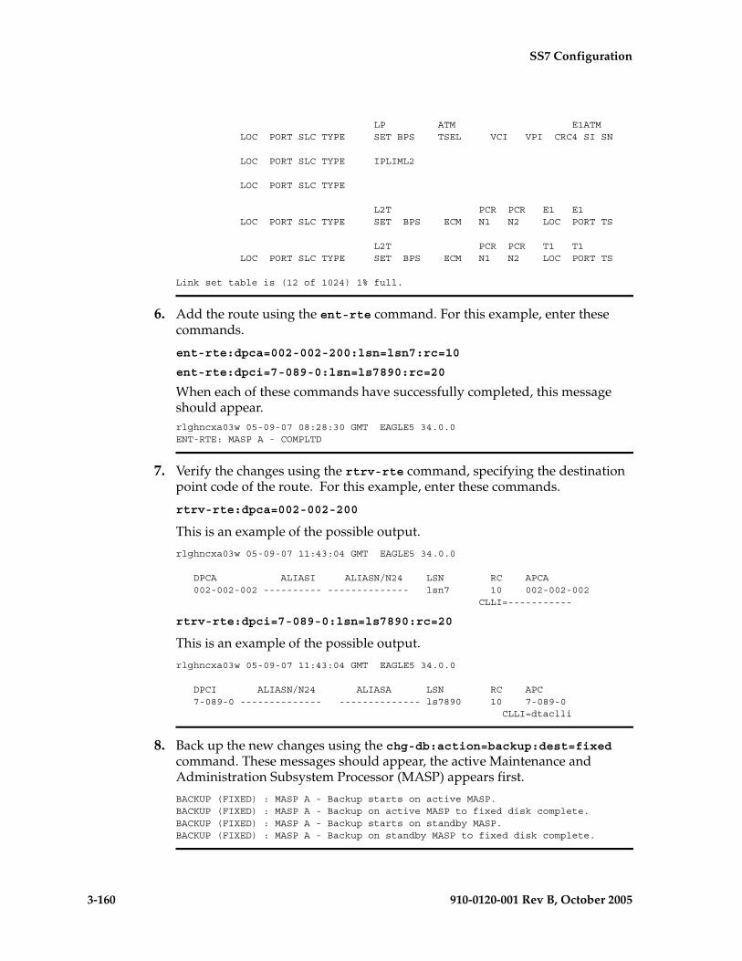
3-160 910-0120-001 Rev B, October 2005
SS7 Configuration
LP ATM E1ATM LOC PORT SLC TYPE SET BPS TSEL VCI VPI CRC4 SI SN
LOC PORT SLC TYPE IPLIML2
LOC PORT SLC TYPE
L2T PCR PCR E1 E1 LOC PORT SLC TYPE SET BPS ECM N1 N2 LOC PORT TS
L2T PCR PCR T1 T1 LOC PORT SLC TYPE SET BPS ECM N1 N2 LOC PORT TS
Link set table is (12 of 1024) 1% full.
6. Add the route using the ent-rte command. For this example, enter these commands.
ent-rte:dpca=002-002-200:lsn=lsn7:rc=10
ent-rte:dpci=7-089-0:lsn=ls7890:rc=20
When each of these commands have successfully completed, this message should appear.rlghncxa03w 05-09-07 08:28:30 GMT EAGLE5 34.0.0ENT-RTE: MASP A - COMPLTD
7. Verify the changes using the rtrv-rte command, specifying the destination point code of the route. For this example, enter these commands.
rtrv-rte:dpca=002-002-200
This is an example of the possible output.
rlghncxa03w 05-09-07 11:43:04 GMT EAGLE5 34.0.0
DPCA ALIASI ALIASN/N24 LSN RC APCA 002-002-002 ---------- -------------- lsn7 10 002-002-002 CLLI=-----------
rtrv-rte:dpci=7-089-0:lsn=ls7890:rc=20
This is an example of the possible output.
rlghncxa03w 05-09-07 11:43:04 GMT EAGLE5 34.0.0
DPCI ALIASN/N24 ALIASA LSN RC APC 7-089-0 -------------- -------------- ls7890 10 7-089-0 CLLI=dtaclli
8. Back up the new changes using the chg-db:action=backup:dest=fixed command. These messages should appear, the active Maintenance and Administration Subsystem Processor (MASP) appears first.
BACKUP (FIXED) : MASP A - Backup starts on active MASP.BACKUP (FIXED) : MASP A - Backup on active MASP to fixed disk complete.BACKUP (FIXED) : MASP A - Backup starts on standby MASP.BACKUP (FIXED) : MASP A - Backup on standby MASP to fixed disk complete.

SS7 Configuration
910-0120-001 Rev B, October 2005 3-161
Flowchart 3-8. Adding a Route Containing an SS7 DPC (Sheet 1 of 3)
Enter the rtrv-rtecommand
Is the pointcode to be assigned to the
route shown in thertrv-dstn output?
Yes
No
Go to the "Adding aDestination Point Code” or"Adding a Network Routing
Point Code" procedure in thismanual and add the point code
to the database.
Are cluster pointcodes shown in the
rtrv-dstn output?
Yes
No
Is the DPCof the route a member
of a cluster?
NoYes
Enter the rtrv-dstncommand with this
parameter::dpc/dpca=<cluster
point code>
What is the NCAIvalue of the cluster
point code?
No
Yes
Do you wishto change the NCAIvalue of the cluster
point code?
No
Yes
ToSheet 2
Go to the "Changing theAttributes of a Cluster Point
Code” procedure in this manualand change the NCAI value of
the cluster point code
ToSheet 2
Go to the "Adding aDestination Point Code” or"Adding a Network Routing
Point Code" procedure in thismanual and add the point code
to the database.
Enter the rtrv-dstncommand
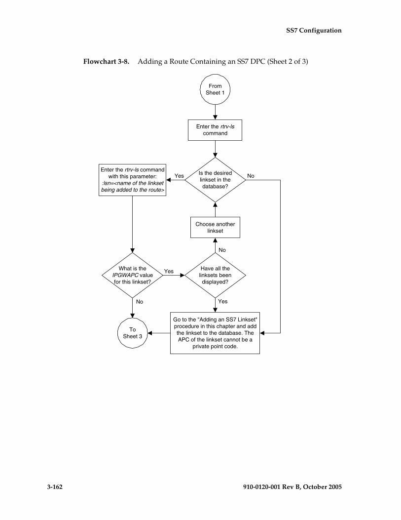
3-162 910-0120-001 Rev B, October 2005
SS7 Configuration
Flowchart 3-8. Adding a Route Containing an SS7 DPC (Sheet 2 of 3)
Is the desiredlinkset in thedatabase?
Enter the rtrv-lscommand
Go to the "Adding an SS7 Linkset"procedure in this chapter and addthe linkset to the database. TheAPC of the linkset cannot be a
private point code.
Yes
ToSheet 3
Yes
NoEnter the rtrv-ls command
with this parameter::lsn=<name of the linksetbeing added to the route>
What is theIPGWAPC valuefor this linkset?
No
Yes
Choose anotherlinkset
Have all thelinksets beendisplayed?
No
FromSheet 1
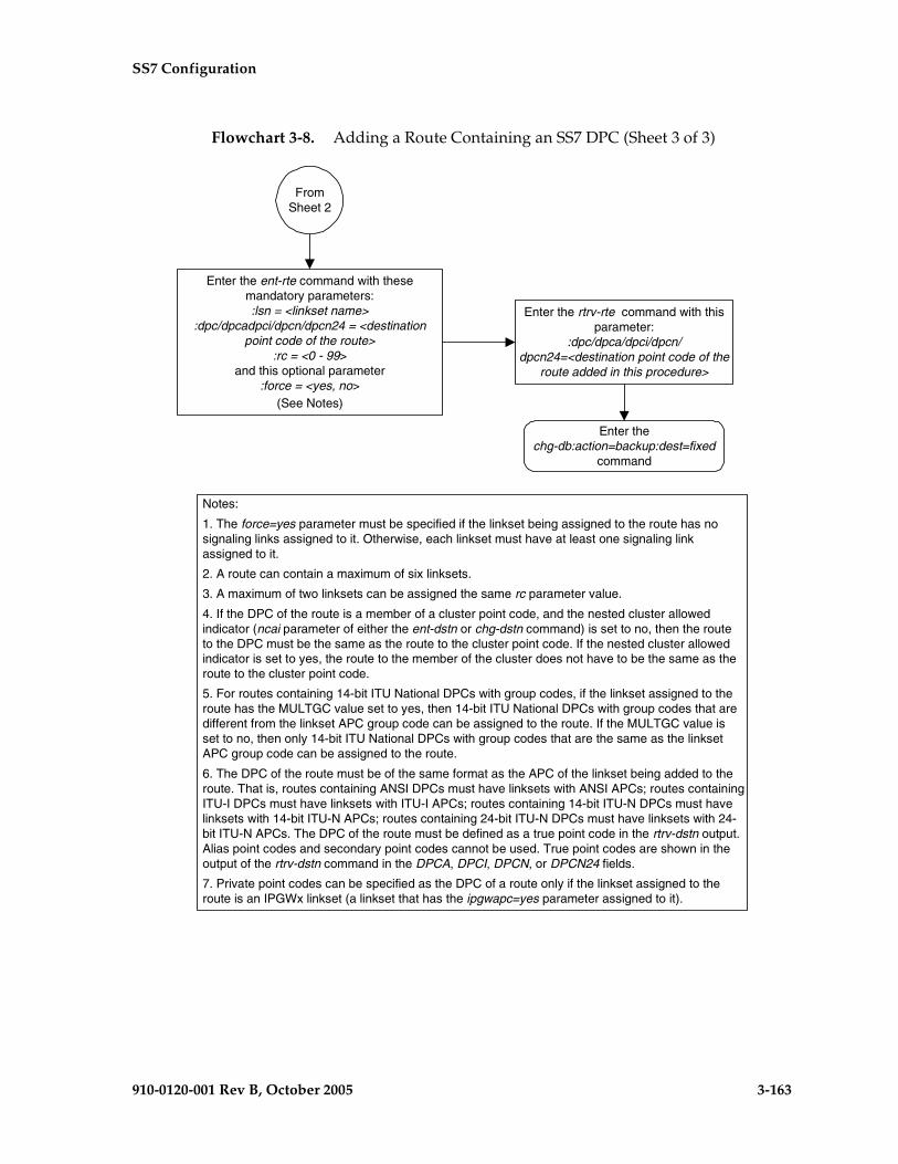
SS7 Configuration
910-0120-001 Rev B, October 2005 3-163
Flowchart 3-8. Adding a Route Containing an SS7 DPC (Sheet 3 of 3)
Enter the ent-rte command with thesemandatory parameters::lsn = <linkset name>
:dpc/dpcadpci/dpcn/dpcn24 = <destinationpoint code of the route>
:rc = <0 - 99>and this optional parameter
:force = <yes, no>(See Notes)
Enter the rtrv-rte command with thisparameter:
:dpc/dpca/dpci/dpcn/dpcn24=<destination point code of the
route added in this procedure>
Enter thechg-db:action=backup:dest=fixed
command
FromSheet 2
Notes:
1. The force=yes parameter must be specified if the linkset being assigned to the route has nosignaling links assigned to it. Otherwise, each linkset must have at least one signaling linkassigned to it.
2. A route can contain a maximum of six linksets.
3. A maximum of two linksets can be assigned the same rc parameter value.
4. If the DPC of the route is a member of a cluster point code, and the nested cluster allowedindicator (ncai parameter of either the ent-dstn or chg-dstn command) is set to no, then the routeto the DPC must be the same as the route to the cluster point code. If the nested cluster allowedindicator is set to yes, the route to the member of the cluster does not have to be the same as theroute to the cluster point code.
5. For routes containing 14-bit ITU National DPCs with group codes, if the linkset assigned to theroute has the MULTGC value set to yes, then 14-bit ITU National DPCs with group codes that aredifferent from the linkset APC group code can be assigned to the route. If the MULTGC value isset to no, then only 14-bit ITU National DPCs with group codes that are the same as the linksetAPC group code can be assigned to the route.
6. The DPC of the route must be of the same format as the APC of the linkset being added to theroute. That is, routes containing ANSI DPCs must have linksets with ANSI APCs; routes containingITU-I DPCs must have linksets with ITU-I APCs; routes containing 14-bit ITU-N DPCs must havelinksets with 14-bit ITU-N APCs; routes containing 24-bit ITU-N DPCs must have linksets with 24-bit ITU-N APCs. The DPC of the route must be defined as a true point code in the rtrv-dstn output.Alias point codes and secondary point codes cannot be used. True point codes are shown in theoutput of the rtrv-dstn command in the DPCA, DPCI, DPCN, or DPCN24 fields.
7. Private point codes can be specified as the DPC of a route only if the linkset assigned to theroute is an IPGWx linkset (a linkset that has the ipgwapc=yes parameter assigned to it).
3-164 910-0120-001 Rev B, October 2005
SS7 Configuration
Adding a Route Containing a Cluster Point Code
This procedure is used to add a route to the database containing a cluster point code as the DPC of the route using the ent-rte command. Routes that do not contain a cluster point code as the DPC of the route are configured in these procedures:
• “Adding a Route Containing an SS7 DPC” on page 3-153
• “Adding a Route Containing an IPGWx Linkset” on page 3-172
• “Adding a Route Containing an X.25 DPC” on page 3-181.
The ent-rte command uses these parameters.
:dpc/dpca – The destination point code (cluster point code) of the node that the traffic is bound for.
NOTE: See “Point Code Formats” on page 2-4 for a definition of the point code types that are used on the EAGLE 5 SAS
:lsn – The name of the linkset that will carry the traffic bound for the node specified by the destination point code.
:rc – The relative cost (priority) for this route.
:force – This parameter allows a route to be added to the database even if the linkset to be assigned to the route does not have any signaling links in it.
These items must be configured in the database before a route can be added:
• Destination point code (DPC) – see “Adding a Cluster Point Code” on page 2-142
• Linkset – see “Adding an SS7 Linkset” on page 3-17
• Link – see “Adding an SS7 Signaling Link” on page 3-130
The linkset assigned to this route must have an adjacent point code (APC) in the SS7 domain. The domain of the DPC is shown in the DOMAIN field in the output of the rtrv-dstn command.
The DPC of the route must be of the same format as the APC of the linkset being added to the route. That is, routes containing ANSI DPCs must have linksets with ANSI APCs; routes containing ITU-I DPCs must have linksets with ITU-I APCs; routes containing 14-bit ITU-N DPCs must have linksets with 14-bit ITU-N APCs; routes containing 24-bit ITU-N DPCs must have linksets with 24-bit ITU-N APCs. The DPC of the route must be defined as a true point code in the rtrv-dstn output. Alias point codes and secondary point codes cannot be used. True point codes are shown in the output of the rtrv-dstn command in the DPCA, DPCI, DPCN, or DPCN24 fields. Private point codes cannot be used as the DPC of a route in this procedure. Routes that have private point codes as the DPC of a route can contain only IPGWx linksets. Perform the “Adding a Route Containing an IPGWx Linkset” on page 3-172 to add routes containing IPGWx linksets.
SS7 Configuration
910-0120-001 Rev B, October 2005 3-165
The DPC of the route is the destination point code to be reached by the route and is shown in the output of the rtrv-rte command in the DPCA, DPCI, DPCN, or DPCN24 fields.
The APCA, APCI, APCN, and APCN24 fields in the output of the rtrv-rte command show the point code of the node that is directly adjacent to the node in the route.
A linkset can only be entered once as a route for each DPC.
A maximum of six routes can be defined for each DPC.
A maximum of two linksets can be assigned the same cost. The cost of the route is defined by the rc parameter of the ent-rte command and is shown in the RC field in the output of the rtrv-rte command.
The force=yes parameter must be specified if the specified linkset has no signaling links assigned to it. Otherwise, each linkset must have at least one signaling link assigned to it.
If the DPC of the route is a cluster point code, only linksets whose linkset type is either B, C, or D can be assigned to the route. The linkset type is shown in the LST field of the rtrv-ls command output. If the linkset type of the desired linkset is either A or E, one of three actions must be taken.
• Choose another linkset with the linkset type B, C, or D.
• Change the linkset type of an existing linkset – go to the “Changing an SS7 Linkset” procedure on page 3-74.
• Add a new linkset to the database with the necessary signaling links and the linkset type B, C, or D.
a. Go to the “Adding an SS7 Linkset” procedure on page 3-17 to add the linkset.
b. If the necessary signaling links are not in the database, go to the “Adding an SS7 Signaling Link” procedure on page 3-130 and add the signaling links to the database.
Canceling the RTRV-LS, RTRV-DSTN, and RTRV-RTE Commands
Because the rtrv-ls, rtrv-dstn, and rtrv-rte commands used in this procedure can output information for a long period of time, the rtrv-ls, rtrv-dstn, and rtrv-rte commands can be canceled and the output to the terminal stopped. There are three ways that the rtrv-ls, rtrv-dstn, and rtrv-rte commands can be canceled.
• Press the F9 function key on the keyboard at the terminal where the rtrv-ls, rtrv-dstn, or rtrv-rte commands were entered.
• Enter the canc-cmd without the trm parameter at the terminal where the rtrv-ls, rtrv-dstn, or rtrv-rte commands were entered.
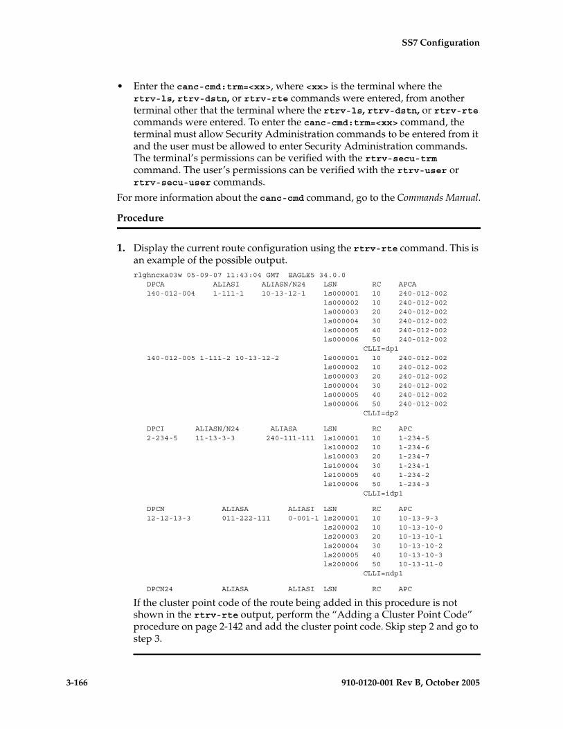
3-166 910-0120-001 Rev B, October 2005
SS7 Configuration
• Enter the canc-cmd:trm=<xx>, where <xx> is the terminal where the rtrv-ls, rtrv-dstn, or rtrv-rte commands were entered, from another terminal other that the terminal where the rtrv-ls, rtrv-dstn, or rtrv-rte commands were entered. To enter the canc-cmd:trm=<xx> command, the terminal must allow Security Administration commands to be entered from it and the user must be allowed to enter Security Administration commands. The terminal’s permissions can be verified with the rtrv-secu-trm command. The user’s permissions can be verified with the rtrv-user or rtrv-secu-user commands.
For more information about the canc-cmd command, go to the Commands Manual.
Procedure
1. Display the current route configuration using the rtrv-rte command. This is an example of the possible output.rlghncxa03w 05-09-07 11:43:04 GMT EAGLE5 34.0.0 DPCA ALIASI ALIASN/N24 LSN RC APCA 140-012-004 1-111-1 10-13-12-1 ls000001 10 240-012-002 ls000002 10 240-012-002 ls000003 20 240-012-002 ls000004 30 240-012-002 ls000005 40 240-012-002 ls000006 50 240-012-002 CLLI=dp1 140-012-005 1-111-2 10-13-12-2 ls000001 10 240-012-002 ls000002 10 240-012-002 ls000003 20 240-012-002 ls000004 30 240-012-002 ls000005 40 240-012-002 ls000006 50 240-012-002 CLLI=dp2
DPCI ALIASN/N24 ALIASA LSN RC APC 2-234-5 11-13-3-3 240-111-111 ls100001 10 1-234-5 ls100002 10 1-234-6 ls100003 20 1-234-7 ls100004 30 1-234-1 ls100005 40 1-234-2 ls100006 50 1-234-3 CLLI=idp1
DPCN ALIASA ALIASI LSN RC APC 12-12-13-3 011-222-111 0-001-1 ls200001 10 10-13-9-3 ls200002 10 10-13-10-0 ls200003 20 10-13-10-1 ls200004 30 10-13-10-2 ls200005 40 10-13-10-3 ls200006 50 10-13-11-0 CLLI=ndp1
DPCN24 ALIASA ALIASI LSN RC APC
If the cluster point code of the route being added in this procedure is not shown in the rtrv-rte output, perform the “Adding a Cluster Point Code” procedure on page 2-142 and add the cluster point code. Skip step 2 and go to step 3.

SS7 Configuration
910-0120-001 Rev B, October 2005 3-167
2. Display the ncai parameter value assigned to the cluster point code using the rtrv-dstn command and specifying the cluster point code. If the ncai parameter value is no, then the route to the DPC must be the same as the route to the cluster point code. If the ncai parameter value is yes, the route to the member of the cluster does not have to be the same as the route to the cluster point code. The ncai value is shown in the NCAI field of the rtrv-dstn output. For this example, enter this command.
rtrv-dstn:dpca=111-011-*
This is an example of the possible output.
rlghncxa03w 05-09-28 21:16:37 GMT EAGLE5 34.0.0 DPCA CLLI BEI ELEI ALIASI ALIASN/N24 DOMAIN 111-011-* rlghncbb000 yes yes ---------- -------------- SS7
SPC NCAI ----------- yes
Destination table is (12 of 2000) 1% full
3. Verify that the required linkset for the route is in the database by displaying the linksets in the database with the rtrv-ls command. This is an example of the possible output.
rlghncxa03w 05-09-10 11:43:04 GMT EAGLE5 34.0.0 L3T SLT GWS GWS GWSLSN APCA (SS7) SCRN SET SET BEI LST LNKS ACT MES DIS SLSCI NISe1e2 001-207-000 none 1 1 no B 6 off off off no offls1305 000-005-000 none 1 1 no A 1 off off off no offls1307 000-007-000 none 1 1 no A 1 off off off no offlsn7 002-002-002 none 1 1 no C 8 off off off no offe1m1s1 001-001-001 none 1 1 no A 7 off off off no offe1m1s2 001-001-002 none 1 1 no A 7 off off off no off
L3T SLT GWS GWS GWSLSN APCA (X25) SCRN SET SET BEI LST LNKS ACT MES DIS SLSCI NIS
L3T SLT GWS GWS GWSLSN APCI (SS7) SCRN SET SET BEI LST LNKS ACT MES DIS SLSCI NISe1e2i 1-207-0 none 1 1 no B 4 off off off --- onls1315 0-015-0 none 1 1 no A 1 off off off --- offls1317 0-017-0 none 1 1 no A 1 off off off --- onls7890 7-089-0 none 1 2 no B 1 off off off --- offe1m2s1 1-011-1 none 1 1 no A 7 off off off --- offe1m2s2 1-011-2 none 1 1 no A 7 off off off --- off
L3T SLT GWS GWS GWSLSN APCN (SS7) SCRN SET SET BEI LST LNKS ACT MES DIS SLSCI NIS
L3T SLT GWS GWS GWSLSN APCN24 (SS7) SCRN SET SET BEI LST LNKS ACT MES DIS SLSCI NIS
L3T SLT GWS GWS GWSLSN (CHINA) APCN (SS7) SCRN SET SET BEI LST LNKS ACT MES DIS SLSCI NIS
L3T SLT GWS GWS GWSLSN (CHINA) APCN24 (SS7) SCRN SET SET BEI LST LNKS ACT MES DIS SLSCI NIS
Link set table is (12 of 1024) 1% full.

3-168 910-0120-001 Rev B, October 2005
SS7 Configuration
The route containing a cluster point code can have only linksets with the linkset types B, C, or D assigned to it. If the required linkset is not in the database, perform the “Adding an SS7 Linkset” procedure on page 3-17 and add the linkset to the database with the ipgwapc=no parameter value and with the linkset types B, C, or D. The APC of the linkset cannot be a private point code. Skip step 4 and go to step 5.
4. Display each linkset being assigned to the route to verify the ipgwapc parameter values with the rtrv-ls command, specifying the name of the linkset that will be assigned to the route.
The ipgwapc linkset parameter value is yes, the DPC of the route cannot be a cluster point code. The ipgwapc value is shown in the IPGWAPC field of the rtrv-ls output.
If the linkset displayed in this step contains the ipgwapc=yes parameter, repeat this step with another linkset shown in step 3. If all the linksets have been displayed, and the ipgwapc value for all the linksets is yes, add the desired linkset by performing the “Adding an SS7 Linkset” procedure on page 3-17 with the ipgwapc=no parameter value and with the linkset types B, C, or D. The APC of the linkset cannot be a private point code.
For this example, enter the following command.
rtrv-ls:lsn=lsn7
This is an example of the possible output.
rlghncxa03w 05-09-17 11:43:04 GMT EAGLE5 34.0.0
L3T SLT GWS GWS GWSLSN APCA (SS7) SCRN SET SET BEI LST LNKS ACT MES DIS SLSCI NISlsn7 002-002-002 none 1 1 no C 8 off off off no off
CLLI TFATCABMLQ MTPRSE ASL8 GSMSCRN ----------- 4 --- no off
IPGWAPC MATELSN IPTPS LSUSEALM SLKUSEALM no ---------- --- --- ---
L2T L1 PCR PCR LOC PORT SLC TYPE SET BPS MODE TSET ECM N1 N2 1211 A 0 LIMDS0 1 56000 --- --- BASIC --- ----- 1211 B 1 LIMDS0 1 56000 --- --- BASIC --- ----- 1211 A1 2 LIMDS0 1 56000 --- --- BASIC --- ----- 1211 A2 3 LIMDS0 1 56000 --- --- BASIC --- ----- 1211 B2 4 LIMDS0 1 56000 --- --- BASIC --- ----- 1211 B1 5 LIMDS0 1 56000 --- --- BASIC --- ----- 1211 B3 6 LIMDS0 1 56000 --- --- BASIC --- ----- 1211 A3 7 LIMDS0 1 56000 --- --- BASIC --- -----
LP ATM LOC PORT SLC TYPE SET BPS TSEL VCI VPI LL
LP ATM E1ATM LOC PORT SLC TYPE SET BPS TSEL VCI VPI CRC4 SI SN
LOC PORT SLC TYPE IPLIML2

SS7 Configuration
910-0120-001 Rev B, October 2005 3-169
LOC PORT SLC TYPE
L2T PCR PCR E1 E1 LOC PORT SLC TYPE SET BPS ECM N1 N2 LOC PORT TS
L2T PCR PCR T1 T1 LOC PORT SLC TYPE SET BPS ECM N1 N2 LOC PORT TS
Link set table is (12 of 1024) 1% full.
5. Add the route using the ent-rte command specifying the cluster point code as the DPC of the route. For this example, enter this command.
ent-rte:dpca=111-011-*:lsn=lsn7:rc=10
When this command has successfully completed, this message should appear.
rlghncxa03w 05-09-07 08:28:30 GMT EAGLE5 34.0.0ENT-RTE: MASP A - COMPLTD
6. Verify the changes using the rtrv-rte command, specifying the destination point code of the route. For this example, enter these commands.
rtrv-rte:dpca=111-011-*
This is an example of the possible output.
rlghncxa03w 05-09-07 11:43:04 GMT EAGLE5 34.0.0
DPCA ALIASI ALIASN/N24 LSN RC APCA 111-011-* ---------- -------------- lsn7 10 002-002-002 CLLI=-----------
7. Back up the new changes using the chg-db:action=backup:dest=fixed command. These messages should appear, the active Maintenance and Administration Subsystem Processor (MASP) appears first.
BACKUP (FIXED) : MASP A - Backup starts on active MASP.BACKUP (FIXED) : MASP A - Backup on active MASP to fixed disk complete.BACKUP (FIXED) : MASP A - Backup starts on standby MASP.BACKUP (FIXED) : MASP A - Backup on standby MASP to fixed disk complete.
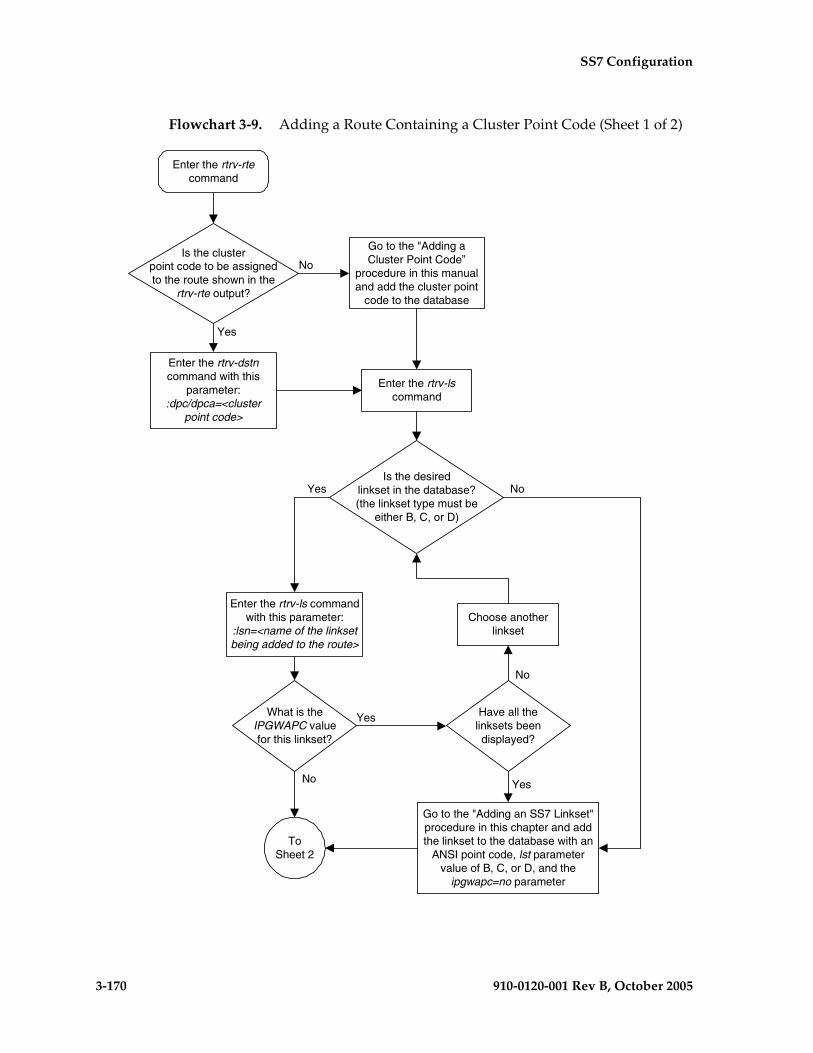
3-170 910-0120-001 Rev B, October 2005
SS7 Configuration
Flowchart 3-9. Adding a Route Containing a Cluster Point Code (Sheet 1 of 2)
Is the clusterpoint code to be assignedto the route shown in the
rtrv-rte output?
Enter the rtrv-dstncommand with this
parameter::dpc/dpca=<cluster
point code>
Is the desiredlinkset in the database?(the linkset type must be
either B, C, or D)
Enter the rtrv-lscommand
Go to the "Adding an SS7 Linkset"procedure in this chapter and addthe linkset to the database with an
ANSI point code, lst parametervalue of B, C, or D, and the
ipgwapc=no parameter
Yes
ToSheet 2
Yes
No
Go to the "Adding aCluster Point Code”
procedure in this manualand add the cluster point
code to the database
Yes
No
Enter the rtrv-ls commandwith this parameter:
:lsn=<name of the linksetbeing added to the route>
What is theIPGWAPC valuefor this linkset?
No
Yes
Choose anotherlinkset
Have all thelinksets beendisplayed?
No
Enter the rtrv-rtecommand
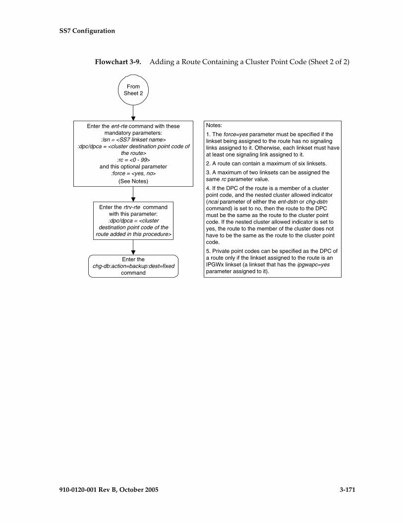
SS7 Configuration
910-0120-001 Rev B, October 2005 3-171
Flowchart 3-9. Adding a Route Containing a Cluster Point Code (Sheet 2 of 2)
Enter the ent-rte command with thesemandatory parameters:
:lsn = <SS7 linkset name>:dpc/dpca = <cluster destination point code of
the route>:rc = <0 - 99>
and this optional parameter:force = <yes, no>
(See Notes)
Enter the rtrv-rte commandwith this parameter::dpc/dpca = <cluster
destination point code of theroute added in this procedure>
Enter thechg-db:action=backup:dest=fixed
command
FromSheet 2
Notes:
1. The force=yes parameter must be specified if thelinkset being assigned to the route has no signalinglinks assigned to it. Otherwise, each linkset must haveat least one signaling link assigned to it.
2. A route can contain a maximum of six linksets.
3. A maximum of two linksets can be assigned thesame rc parameter value.
4. If the DPC of the route is a member of a clusterpoint code, and the nested cluster allowed indicator(ncai parameter of either the ent-dstn or chg-dstncommand) is set to no, then the route to the DPCmust be the same as the route to the cluster pointcode. If the nested cluster allowed indicator is set toyes, the route to the member of the cluster does nothave to be the same as the route to the cluster pointcode.
5. Private point codes can be specified as the DPC ofa route only if the linkset assigned to the route is anIPGWx linkset (a linkset that has the ipgwapc=yesparameter assigned to it).

3-172 910-0120-001 Rev B, October 2005
SS7 Configuration
Adding a Route Containing an IPGWx Linkset
This procedure is used to add a route to the database containing an IPGWx linkset using the ent-rte command. Routes that do not contain IPGWx linksets are configured in these procedures:
• “Adding a Route Containing an SS7 DPC” on page 3-153
• “Adding a Route Containing a Cluster Point Code” on page 3-164
• “Adding a Route Containing an X.25 DPC” on page 3-181.
The ent-rte command uses these parameters.
:dpc/dpca/dpci/dpcn/dpcn24 – The destination point code of the node that the traffic is bound for.
NOTE: See “Point Code Formats” on page 2-4 for a definition of the point code types that are used on the EAGLE 5 SAS and for a definition of the different formats that can be used for ITU national point codes.
:lsn – The name of the linkset that will carry the traffic bound for the node specified by the destination point code.
:rc – The relative cost (priority) for this route.
:force – This parameter allows a route to be added to the database even if the linkset to be assigned to the route does not have any signaling links in it.
These items must be configured in the database before a route can be added:
• Destination point code (DPC) – see “Adding a Destination Point Code” on page 2-191. The DPC of the route can be a private point code, but does not have to be.
• Linkset – see “Adding an SS7 Linkset” on page 3-17
• Link – see “Adding an SS7 Signaling Link” on page 3-130
The linkset assigned to this route must have an adjacent point code (APC) in the SS7 domain and must contain the ipgwapc=yes parameter value. The domain of the DPC is shown in the DOMAIN field in the output of the rtrv-dstn command. The ipgwapc parameter value is shown in the output of the rtrv-ls:lsn=<linkset name> command.
The DPC of the route must be of the same format as the APC of the linkset being added to the route. That is, routes containing ANSI DPCs must have linksets with ANSI APCs; routes containing ITU-I DPCs must have linksets with ITU-I APCs; routes containing 14-bit ITU-N DPCs must have linksets with 14-bit ITU-N APCs; routes containing 24-bit ITU-N DPCs must have linksets with 24-bit ITU-N APCs. The DPC of the route must be defined as a true point code in the rtrv-dstn output. Alias point codes and secondary point codes cannot be used. True point codes are shown in the output of the rtrv-dstn command in the DPCA, DPCI, DPCN, or DPCN24 fields.
SS7 Configuration
910-0120-001 Rev B, October 2005 3-173
The DPC of the route is the destination point code to be reached by the route and is shown in the output of the rtrv-rte command in the DPCA, DPCI, DPCN, or DPCN24 fields.
The APCA, APCI, APCN, and APCN24 fields in the output of the rtrv-rte command show the point code of the node that is directly adjacent to the node in the route.
A linkset can only be entered once as a route for each DPC.
A maximum of six routes can be defined for each DPC.
A maximum of two linksets can be assigned the same cost. The cost of the route is defined by the rc parameter of the ent-rte command and is shown in the RC field in the output of the rtrv-rte command.
The force=yes parameter must be specified if the specified linkset has no signaling links assigned to it. Otherwise, each linkset must have at least one signaling link assigned to it.
The DPC of the route must be a full point code.
If the DPC of the route is a member of a cluster point code, and the nested cluster allowed indicator (ncai parameter of either the ent-dstn or chg-dstn command) is set to no, then the route to the DPC must be the same as the route to the cluster point code. If the nested cluster allowed indicator is set to yes, the route to the member of the cluster does not have to be the same as the route to the cluster point code. For more information, see the “Nested Cluster Routing” section on page 2-135.
For routes containing 14-bit ITU National DPCs with group codes, if the linkset assigned to the route has the MULTGC value set to yes, then 14-bit ITU National DPCs with group codes that are different from the linkset APC group code can be assigned to the route. If the MULTGC value is set to no, then only 14-bit ITU National DPCs with group codes that are the same as the linkset APC group code can be assigned to the route.
Canceling the RTRV-LS, RTRV-DSTN, and RTRV-RTE Commands
Because the rtrv-ls, rtrv-dstn, and rtrv-rte commands used in this procedure can output information for a long period of time, the rtrv-ls, rtrv-dstn, and rtrv-rte commands can be canceled and the output to the terminal stopped. There are three ways that the rtrv-ls, rtrv-dstn, and rtrv-rte commands can be canceled.
• Press the F9 function key on the keyboard at the terminal where the rtrv-ls, rtrv-dstn, or rtrv-rte commands were entered.
• Enter the canc-cmd without the trm parameter at the terminal where the rtrv-ls, rtrv-dstn, or rtrv-rte commands were entered.
• Enter the canc-cmd:trm=<xx>, where <xx> is the terminal where the rtrv-ls, rtrv-dstn, or rtrv-rte commands were entered, from another

3-174 910-0120-001 Rev B, October 2005
SS7 Configuration
terminal other that the terminal where the rtrv-ls, rtrv-dstn, or rtrv-rte commands were entered. To enter the canc-cmd:trm=<xx> command, the terminal must allow Security Administration commands to be entered from it and the user must be allowed to enter Security Administration commands. The terminal’s permissions can be verified with the rtrv-secu-trm command. The user’s permissions can be verified with the rtrv-user or rtrv-secu-user commands.
For more information about the canc-cmd command, go to the Commands Manual.
Procedure
1. Display the current route configuration using the rtrv-rte command. This is an example of the possible output.
rlghncxa03w 05-09-07 11:43:04 GMT EAGLE5 34.0.0 DPCA ALIASI ALIASN/N24 LSN RC APCA 140-012-004 1-111-1 10-13-12-1 ls000001 10 240-012-002 ls000002 10 240-012-002 ls000003 20 240-012-002 ls000004 30 240-012-002 ls000005 40 240-012-002 ls000006 50 240-012-002 CLLI=dp1 140-012-005 1-111-2 10-13-12-2 ls000001 10 240-012-002 ls000002 10 240-012-002 ls000003 20 240-012-002 ls000004 30 240-012-002 ls000005 40 240-012-002 ls000006 50 240-012-002 CLLI=dp2
DPCI ALIASN/N24 ALIASA LSN RC APC 2-234-5 11-13-3-3 240-111-111 ls100001 10 1-234-5 ls100002 10 1-234-6 ls100003 20 1-234-7 ls100004 30 1-234-1 ls100005 40 1-234-2 ls100006 50 1-234-3 CLLI=idp1
DPCN ALIASA ALIASI LSN RC APC 12-12-13-3 011-222-111 0-001-1 ls200001 10 10-13-9-3 ls200002 10 10-13-10-0 ls200003 20 10-13-10-1 ls200004 30 10-13-10-2 ls200005 40 10-13-10-3 ls200006 50 10-13-11-0 CLLI=ndp1
DPCN24 ALIASA ALIASI LSN RC APC
If the destination point code of the route being added in this procedure is not shown in the rtrv-rte output, perform the “Adding a Destination Point Code” procedure on page 2-191 and add the destination point code of the route to the destination point code table. This point code can be a private point code, but does not have to be a private point code.

SS7 Configuration
910-0120-001 Rev B, October 2005 3-175
NOTE: If cluster point codes are not shown in steps 1 and 2, or if the DPC of the route being added is not a member of the cluster point code, skip this step and go to step 4.
2. Display the ncai parameter value assigned to the cluster point code using the rtrv-dstn command and specifying the cluster point code. If the ncai parameter value is no, then the route to the DPC must be the same as the route to the cluster point code. If the ncai parameter value is yes, the route to the member of the cluster does not have to be the same as the route to the cluster point code. The ncai value is shown in the NCAI field of the rtrv-dstn output. For this example, enter this command.
rtrv-dstn:dpca=111-011-*
This is an example of the possible output.
rlghncxa03w 05-09-28 21:16:37 GMT EAGLE5 34.0.0 DPCA CLLI BEI ELEI ALIASI ALIASN/N24 DOMAIN 111-011-* rlghncbb000 yes yes ---------- -------------- SS7
SPC NCAI ----------- yes
Destination table is (12 of 2000) 1% full
If the ncai parameter value of the cluster point code is no, and you wish to change the ncai parameter value to yes, perform the “Changing the Attributes of a Cluster Point Code” procedure on page 2-161. If the ncai parameter value of the cluster point code is no, and you do not wish to change the ncai parameter value to yes, add a new DPC for the route by performing either the “Adding a Destination Point Code” procedure on page 2-191 or the “Adding a Network Routing Point Code” procedure on page 2-181.
3. Verify that the required linkset for the route is in the database by displaying the linksets in the database with the rtrv-ls command. This is an example of the possible output.
rlghncxa03w 05-09-10 11:43:04 GMT EAGLE5 34.0.0
L3T SLT GWS GWS GWSLSN APCA (SS7) SCRN SET SET BEI LST LNKS ACT MES DIS SLSCI NISe1e2 001-207-000 none 1 1 no B 6 off off off no offls1305 000-005-000 none 1 1 no A 1 off off off no offls1307 000-007-000 none 1 1 no A 1 off off off no offlsn4 p-004-004-004 none 1 1 no A 6 off off off no offe1m1s1 001-001-001 none 1 1 no A 7 off off off no offe1m1s2 001-001-002 none 1 1 no A 7 off off off no off
L3T SLT GWS GWS GWSLSN APCA (X25) SCRN SET SET BEI LST LNKS ACT MES DIS SLSCI NIS
L3T SLT GWS GWS GWSLSN APCI (SS7) SCRN SET SET BEI LST LNKS ACT MES DIS SLSCI NISe1e2i 1-207-0 none 1 1 no B 4 off off off --- onls1315 0-015-0 none 1 1 no A 1 off off off --- offls1317 0-017-0 none 1 1 no A 1 off off off --- one1m2s1 1-011-1 none 1 1 no A 7 off off off --- offe1m2s2 1-011-2 none 1 1 no A 7 off off off --- off
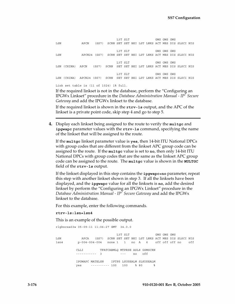
3-176 910-0120-001 Rev B, October 2005
SS7 Configuration
L3T SLT GWS GWS GWSLSN APCN (SS7) SCRN SET SET BEI LST LNKS ACT MES DIS SLSCI NIS
L3T SLT GWS GWS GWSLSN APCN24 (SS7) SCRN SET SET BEI LST LNKS ACT MES DIS SLSCI NIS
L3T SLT GWS GWS GWSLSN (CHINA) APCN (SS7) SCRN SET SET BEI LST LNKS ACT MES DIS SLSCI NIS
L3T SLT GWS GWS GWSLSN (CHINA) APCN24 (SS7) SCRN SET SET BEI LST LNKS ACT MES DIS SLSCI NIS
Link set table is (11 of 1024) 1% full.
If the required linkset is not in the database, perform the “Configuring an IPGWx Linkset” procedure in the Database Administration Manual - IP7 Secure Gateway and add the IPGWx linkset to the database.If the required linkset is shown in the rtrv-ls output, and the APC of the linkset is a private point code, skip step 4 and go to step 5.
4. Display each linkset being assigned to the route to verify the multgc and ipgwapc parameter values with the rtrv-ls command, specifying the name of the linkset that will be assigned to the route.
If the multgc linkset parameter value is yes, then 14-bit ITU National DPCs with group codes that are different from the linkset APC group code can be assigned to the route. If the multgc value is set to no, then only 14-bit ITU National DPCs with group codes that are the same as the linkset APC group code can be assigned to the route. The multgc value is shown in the MULTGC field of the rtrv-ls output.
If the linkset displayed in this step contains the ipgwapc=no parameter, repeat this step with another linkset shown in step 3. If all the linksets have been displayed, and the ipgwapc value for all the linksets is no, add the desired linkset by perform the “Configuring an IPGWx Linkset” procedure in the Database Administration Manual - IP7 Secure Gateway and add the IPGWx linkset to the database.
For this example, enter the following commands.
rtrv-ls:lsn=lsn4
This is an example of the possible output.
rlghncxa03w 05-09-11 11:06:27 GMT 34.0.0
L3T SLT GWS GWS GWSLSN APCA (SS7) SCRN SET SET BEI LST LNKS ACT MES DIS SLSCI NISlsn4 p-004-004-004 none 1 1 no A 6 off off off no off
CLLI TFATCABMLQ MTPRSE ASL8 GSMSCRN ----------- 3 --- no off
IPGWAPC MATELSN IPTPS LSUSEALM SLKUSEALM yes ---------- 100 100 % 80 %

SS7 Configuration
910-0120-001 Rev B, October 2005 3-177
L2T L1 PCR PCR LOC PORT SLC TYPE SET BPS MODE TSET ECM N1 N2
LP ATM LOC PORT SLC TYPE SET BPS TSEL VCI VPI LL
LP ATM E1ATM LOC PORT SLC TYPE SET BPS TSEL VCI VPI CRC4 SI SN
LOC PORT SLC TYPE IPLIML2
LOC PORT SLC TYPE 1107 A 0 SS7IPGW 1205 A 1 SS7IPGW 1305 A 2 SS7IPGW 1303 A 3 SS7IPGW 1307 A 4 SS7IPGW 1311 A 5 SS7IPGW
L2T PCR PCR E1 E1 LOC PORT SLC TYPE SET BPS ECM N1 N2 LOC PORT TS
L2T PCR PCR T1 T1 LOC PORT SLC TYPE SET BPS ECM N1 N2 LOC PORT TS
Link set table is (16 of 1024) 1% full.
5. Add the route using the ent-rte command with the IPGWx linkset. For this example, enter this command.
ent-rte:dpca=p-004-004-004:lsn=lsn4:rc=10
When this command has successfully completed, this message should appear.rlghncxa03w 05-09-07 08:28:30 GMT EAGLE5 34.0.0ENT-RTE: MASP A - COMPLTD
6. Verify the changes using the rtrv-rte command, specifying the destination point code of the route. For this example, enter this command.
rtrv-rte:dpca=p-004-004-004
This is an example of the possible output.
rlghncxa03w 05-09-07 11:43:04 GMT EAGLE5 34.0.0
DPCA ALIASI ALIASN/N24 LSN RC APCAp-004-004-004 ---------- s-00444-aa lsn4 10 p-004-004-004 CLLI=-----------
7. Back up the new changes using the chg-db:action=backup:dest=fixed command. These messages should appear, the active Maintenance and Administration Subsystem Processor (MASP) appears first.
BACKUP (FIXED) : MASP A - Backup starts on active MASP.BACKUP (FIXED) : MASP A - Backup on active MASP to fixed disk complete.BACKUP (FIXED) : MASP A - Backup starts on standby MASP.BACKUP (FIXED) : MASP A - Backup on standby MASP to fixed disk complete.

3-178 910-0120-001 Rev B, October 2005
SS7 Configuration
Flowchart 3-10. Adding a Route Containing an IPGWx Linkset (Sheet 1 of 3)
Enter the rtrv-rtecommand
Is the pointcode to be assigned to the
route shown in thertrv-rte output?
Yes
No
Go to the "Adding aDestination Point Code”
procedure in this manual andadd the point code to the
database. This point code canbe, but does not have to be, a
private point code.
Are cluster pointcodes shown in the
rtrv-dstn output?
Yes
No
Is the DPCof the route a member
of a cluster?
NoYes
Enter the rtrv-dstncommand with this
parameter::dpc/dpca=<cluster
point code>
What is the NCAIvalue of the cluster
point code?
No
Yes
Do you wishto change the NCAIvalue of the cluster
point code?
No
Yes
ToSheet 2
Go to the "Changing theAttributes of a Cluster Point
Code” procedure in this manualand change the NCAI value of
the cluster point code
ToSheet 2
Go to the "Adding aDestination Point Code”
procedure in this manual andadd the point code to the
database. This point code canbe, but does not have to be, a
private point code.

SS7 Configuration
910-0120-001 Rev B, October 2005 3-179
Flowchart 3-10. Adding a Route Containing an IPGWx Linkset (Sheet 2 of 3)
Is the desiredlinkset in thedatabase?
Enter the rtrv-lscommand
Go to the "Configuring an IPGWxLinkset" procedure in Database
Administration Manual - IP7 SecureGateway and add the linkset to the
database with the ipgwapc=yesparameter. The APC of the linkset
can be a private point code.
Yes
No
ToSheet 3
Is the APC ofthe linkset a private
point code?
Yes
Yes No
Enter the rtrv-ls commandwith this parameter:
:lsn=<name of the linksetbeing added to the route>
What is theIPGWAPC valuefor this linkset?
No
Yes
Choose anotherlinkset
Have all thelinksets beendisplayed?
No
FromSheet 1

3-180 910-0120-001 Rev B, October 2005
SS7 Configuration
Flowchart 3-10. Adding a Route Containing an IPGWx Linkset (Sheet 3 of 3)
Enter the ent-rte command with thesemandatory parameters:
:lsn = <IPGWx linkset name>:dpc/dpcadpci/dpcn/dpcn24 = <destination
point code of the route>:rc = <0 - 99>
and this optional parameter:force = <yes, no>
(See Notes)
Enter the rtrv-rte command with thisparameter:
:dpc/dpca/dpci/dpcn/dpcn24=<destination point code of the
route added in this procedure>
Enter thechg-db:action=backup:dest=fixed
command
FromSheet 2
Notes:
1. The force=yes parameter must be specified if the linkset being assigned to the route has nosignaling links assigned to it. Otherwise, each linkset must have at least one signaling linkassigned to it.
2. A route can contain a maximum of six linksets.
3. For an SS7 route, a maximum of two linksets can be assigned the same rc parameter value.
4. If the DPC of the route is a member of a cluster point code, and the nested cluster allowedindicator (ncai parameter of either the ent-dstn or chg-dstn command) is set to no, then the routeto the DPC must be the same as the route to the cluster point code. If the nested cluster allowedindicator is set to yes, the route to the member of the cluster does not have to be the same as theroute to the cluster point code.
5. For routes containing 14-bit ITU National DPCs with group codes, if the linkset assigned to theroute has the MULTGC value set to yes, then 14-bit ITU National DPCs with group codes that aredifferent from the linkset APC group code can be assigned to the route. If the MULTGC value isset to no, then only 14-bit ITU National DPCs with group codes that are the same as the linksetAPC group code can be assigned to the route.
6. The DPC of the route must be of the same format as the APC of the linkset being added to theroute. That is, routes containing ANSI DPCs must have linksets with ANSI APCs; routes containingITU-I DPCs must have linksets with ITU-I APCs; routes containing 14-bit ITU-N DPCs must havelinksets with 14-bit ITU-N APCs; routes containing 24-bit ITU-N DPCs must have linksets with 24-bit ITU-N APCs. The DPC of the route must be defined as a true point code in the rtrv-dstn output.Alias point codes and secondary point codes cannot be used. True point codes are shown in theoutput of the rtrv-dstn command in the DPCA, DPCI, DPCN, or DPCN24 fields.
7. Private point codes can be specified as the DPC of a route only if the linkset assigned to theroute is an IPGWx linkset (a linkset that has the ipgwapc=yes parameter assigned to it).

SS7 Configuration
910-0120-001 Rev B, October 2005 3-181
Adding a Route Containing an X.25 DPC
This procedure is used to add a route to the database containing an X.25 point code as the DPC of the route using the ent-rte command. Routes that do not contain an X.25 point code as the DPC of the route are configured in these procedures:
• “Adding a Route Containing an SS7 DPC” on page 3-153
• “Adding a Route Containing a Cluster Point Code” on page 3-164
• “Adding a Route Containing an IPGWx Linkset” on page 3-172.
The ent-rte command uses these parameters.
:dpc/dpca – The X.25 destination point code of the node that the traffic is bound for.
NOTE: See “Point Code Formats” on page 2-4 for a definition of the point code types that are used on the EAGLE 5 SAS.
:lsn – The name of the linkset that will carry the traffic bound for the node specified by the destination point code.
:rc – The relative cost (priority) for this route.
:force – This parameter allows a route to be added to the database even if the linkset to be assigned to the route does not have any signaling links in it.
These items must be configured in the database before a route can be added:
• X.25 Destination point code (DPC) – see “Adding a Destination Point Code” on page 2-191.
• X.25 Linkset – see “Adding an X.25 Linkset” procedure in the Database Administration Manual – Features.
• X.25 Signaling Link – see “Adding an X.25 Signaling Link” procedure in the Database Administration Manual – Features.
• X.25 destination (if an X.25 route is to be added) – see the “Adding an X.25 Gateway Destination” procedure in the Database Administration Manual – Features.
The linkset assigned to this route must have an APC in the X.25 domain. The domain of the DPC is shown in the DOMAIN field in the output of the rtrv-dstn command.
If the destination of a route (DPC/DPCA) is in the X.25 domain, no routes to that destination can be assigned the same cost value (RC) in the same routeset. If two routes in a routeset were assigned the same cost value, this creates a combined linkset and combined linksets to DPCs in the X.25 domain are not allowed.
The DPC of the route is the destination point code to be reached by the route and is shown in the output of the rtrv-rte command in the DPCA field.
3-182 910-0120-001 Rev B, October 2005
SS7 Configuration
A linkset can only be entered once as a route for each DPC.
A maximum of six routes can be defined for each DPC.
The force=yes parameter must be specified if the specified linkset has no signaling links assigned to it. Otherwise, each linkset must have at least one signaling link assigned to it.
If the route is assigned a DPC that is in the X.25 domain, then that DPC must be assigned to at least one X.25 destination.
If the DPC of the route is a member of a cluster point code, and the nested cluster allowed indicator (ncai parameter of either the ent-dstn or chg-dstn command) is set to no, then the route to the DPC must be the same as the route to the cluster point code. If the nested cluster allowed indicator is set to yes, the route to the member of the cluster does not have to be the same as the route to the cluster point code. For more information, see the “Nested Cluster Routing” section on page 2-135.
Canceling the RTRV-LS, RTRV-DSTN, and RTRV-RTE Commands
Because the rtrv-ls, rtrv-dstn, and rtrv-rte commands used in this procedure can output information for a long period of time, the rtrv-ls, rtrv-dstn, and rtrv-rte commands can be canceled and the output to the terminal stopped. There are three ways that the rtrv-ls, rtrv-dstn, and rtrv-rte commands can be canceled.
• Press the F9 function key on the keyboard at the terminal where the rtrv-ls, rtrv-dstn, or rtrv-rte commands were entered.
• Enter the canc-cmd without the trm parameter at the terminal where the rtrv-ls, rtrv-dstn, or rtrv-rte commands were entered.
• Enter the canc-cmd:trm=<xx>, where <xx> is the terminal where the rtrv-ls, rtrv-dstn, or rtrv-rte commands were entered, from another terminal other that the terminal where the rtrv-ls, rtrv-dstn, or rtrv-rte commands were entered. To enter the canc-cmd:trm=<xx> command, the terminal must allow Security Administration commands to be entered from it and the user must be allowed to enter Security Administration commands. The terminal’s permissions can be verified with the rtrv-secu-trm command. The user’s permissions can be verified with the rtrv-user or rtrv-secu-user commands.
For more information about the canc-cmd command, go to the Commands Manual.
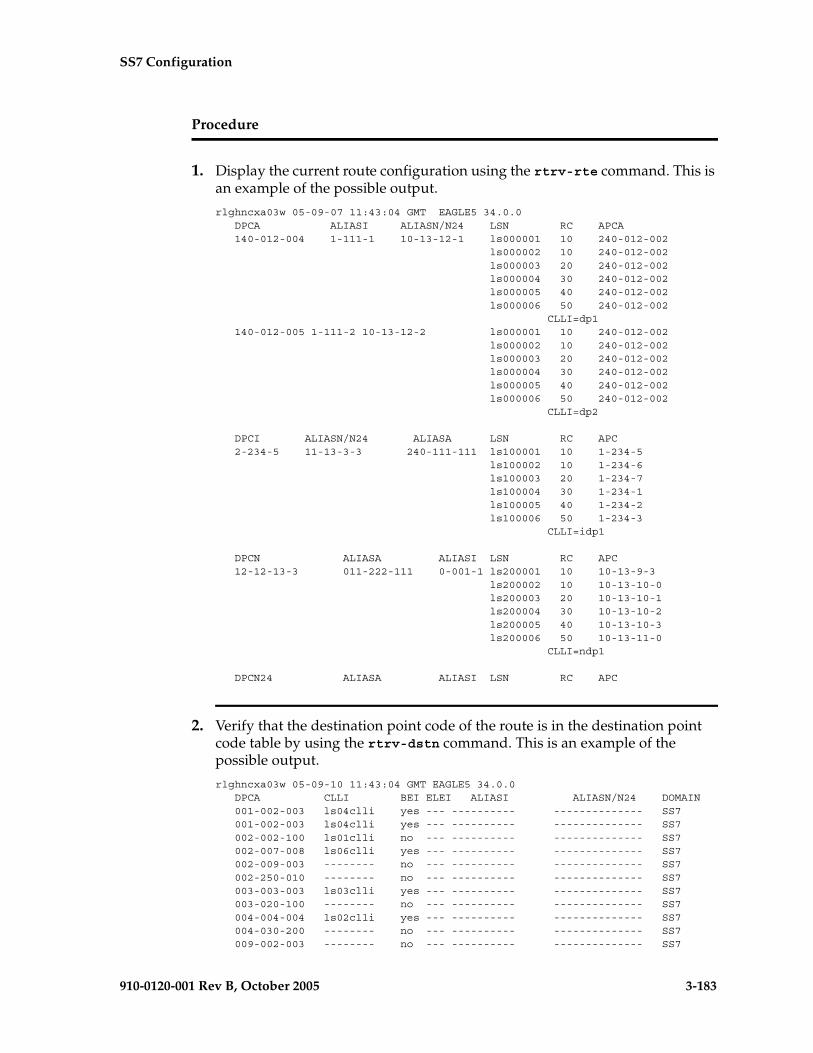
SS7 Configuration
910-0120-001 Rev B, October 2005 3-183
Procedure
1. Display the current route configuration using the rtrv-rte command. This is an example of the possible output.
rlghncxa03w 05-09-07 11:43:04 GMT EAGLE5 34.0.0 DPCA ALIASI ALIASN/N24 LSN RC APCA 140-012-004 1-111-1 10-13-12-1 ls000001 10 240-012-002 ls000002 10 240-012-002 ls000003 20 240-012-002 ls000004 30 240-012-002 ls000005 40 240-012-002 ls000006 50 240-012-002 CLLI=dp1 140-012-005 1-111-2 10-13-12-2 ls000001 10 240-012-002 ls000002 10 240-012-002 ls000003 20 240-012-002 ls000004 30 240-012-002 ls000005 40 240-012-002 ls000006 50 240-012-002 CLLI=dp2
DPCI ALIASN/N24 ALIASA LSN RC APC 2-234-5 11-13-3-3 240-111-111 ls100001 10 1-234-5 ls100002 10 1-234-6 ls100003 20 1-234-7 ls100004 30 1-234-1 ls100005 40 1-234-2 ls100006 50 1-234-3 CLLI=idp1
DPCN ALIASA ALIASI LSN RC APC 12-12-13-3 011-222-111 0-001-1 ls200001 10 10-13-9-3 ls200002 10 10-13-10-0 ls200003 20 10-13-10-1 ls200004 30 10-13-10-2 ls200005 40 10-13-10-3 ls200006 50 10-13-11-0 CLLI=ndp1
DPCN24 ALIASA ALIASI LSN RC APC
2. Verify that the destination point code of the route is in the destination point code table by using the rtrv-dstn command. This is an example of the possible output.
rlghncxa03w 05-09-10 11:43:04 GMT EAGLE5 34.0.0 DPCA CLLI BEI ELEI ALIASI ALIASN/N24 DOMAIN 001-002-003 ls04clli yes --- ---------- -------------- SS7 001-002-003 ls04clli yes --- ---------- -------------- SS7 002-002-100 ls01clli no --- ---------- -------------- SS7 002-007-008 ls06clli yes --- ---------- -------------- SS7 002-009-003 -------- no --- ---------- -------------- SS7 002-250-010 -------- no --- ---------- -------------- SS7 003-003-003 ls03clli yes --- ---------- -------------- SS7 003-020-100 -------- no --- ---------- -------------- SS7 004-004-004 ls02clli yes --- ---------- -------------- SS7 004-030-200 -------- no --- ---------- -------------- SS7 009-002-003 -------- no --- ---------- -------------- SS7
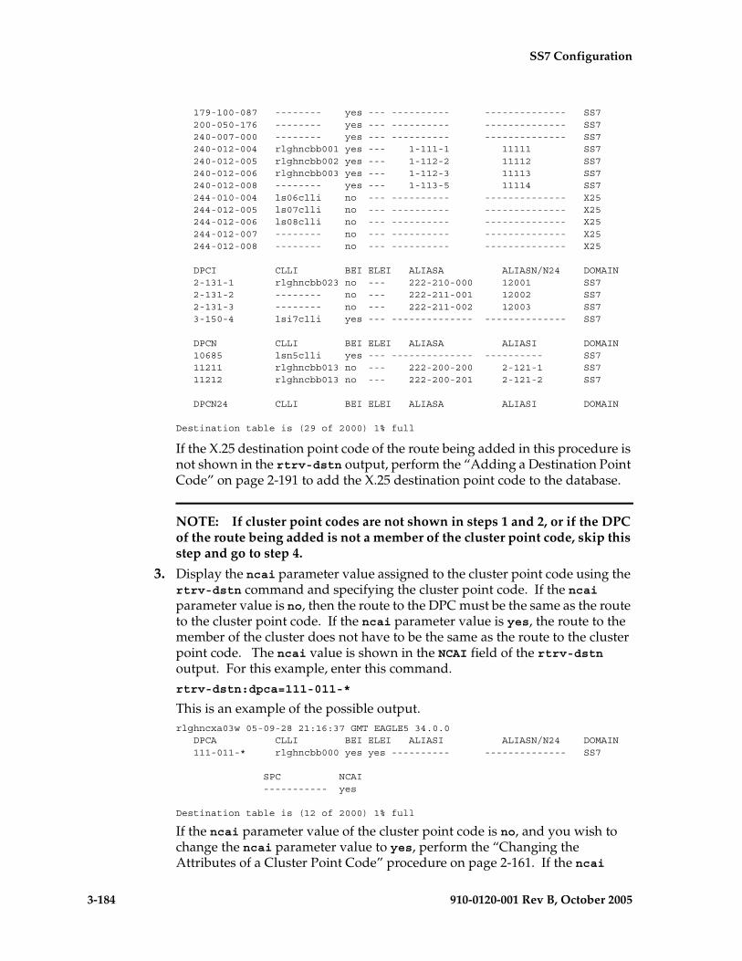
3-184 910-0120-001 Rev B, October 2005
SS7 Configuration
179-100-087 -------- yes --- ---------- -------------- SS7 200-050-176 -------- yes --- ---------- -------------- SS7 240-007-000 -------- yes --- ---------- -------------- SS7 240-012-004 rlghncbb001 yes --- 1-111-1 11111 SS7 240-012-005 rlghncbb002 yes --- 1-112-2 11112 SS7 240-012-006 rlghncbb003 yes --- 1-112-3 11113 SS7 240-012-008 -------- yes --- 1-113-5 11114 SS7 244-010-004 ls06clli no --- ---------- -------------- X25 244-012-005 ls07clli no --- ---------- -------------- X25 244-012-006 ls08clli no --- ---------- -------------- X25 244-012-007 -------- no --- ---------- -------------- X25 244-012-008 -------- no --- ---------- -------------- X25
DPCI CLLI BEI ELEI ALIASA ALIASN/N24 DOMAIN 2-131-1 rlghncbb023 no --- 222-210-000 12001 SS7 2-131-2 -------- no --- 222-211-001 12002 SS7 2-131-3 -------- no --- 222-211-002 12003 SS7 3-150-4 lsi7clli yes --- -------------- -------------- SS7
DPCN CLLI BEI ELEI ALIASA ALIASI DOMAIN 10685 lsn5clli yes --- -------------- ---------- SS7 11211 rlghncbb013 no --- 222-200-200 2-121-1 SS7 11212 rlghncbb013 no --- 222-200-201 2-121-2 SS7
DPCN24 CLLI BEI ELEI ALIASA ALIASI DOMAIN
Destination table is (29 of 2000) 1% full
If the X.25 destination point code of the route being added in this procedure is not shown in the rtrv-dstn output, perform the “Adding a Destination Point Code” on page 2-191 to add the X.25 destination point code to the database.
NOTE: If cluster point codes are not shown in steps 1 and 2, or if the DPC of the route being added is not a member of the cluster point code, skip this step and go to step 4.
3. Display the ncai parameter value assigned to the cluster point code using the rtrv-dstn command and specifying the cluster point code. If the ncai parameter value is no, then the route to the DPC must be the same as the route to the cluster point code. If the ncai parameter value is yes, the route to the member of the cluster does not have to be the same as the route to the cluster point code. The ncai value is shown in the NCAI field of the rtrv-dstn output. For this example, enter this command.rtrv-dstn:dpca=111-011-*
This is an example of the possible output.rlghncxa03w 05-09-28 21:16:37 GMT EAGLE5 34.0.0 DPCA CLLI BEI ELEI ALIASI ALIASN/N24 DOMAIN 111-011-* rlghncbb000 yes yes ---------- -------------- SS7
SPC NCAI ----------- yes
Destination table is (12 of 2000) 1% full
If the ncai parameter value of the cluster point code is no, and you wish to change the ncai parameter value to yes, perform the “Changing the Attributes of a Cluster Point Code” procedure on page 2-161. If the ncai
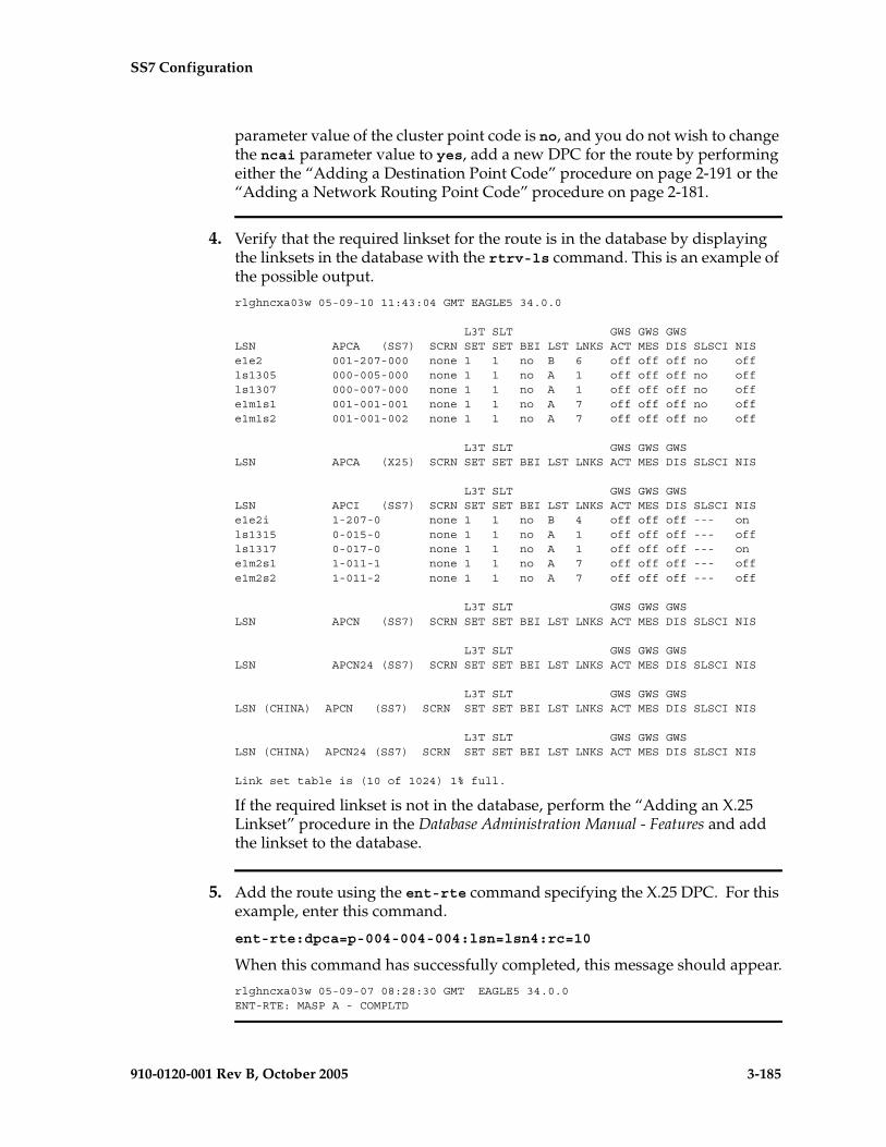
SS7 Configuration
910-0120-001 Rev B, October 2005 3-185
parameter value of the cluster point code is no, and you do not wish to change the ncai parameter value to yes, add a new DPC for the route by performing either the “Adding a Destination Point Code” procedure on page 2-191 or the “Adding a Network Routing Point Code” procedure on page 2-181.
4. Verify that the required linkset for the route is in the database by displaying the linksets in the database with the rtrv-ls command. This is an example of the possible output.
rlghncxa03w 05-09-10 11:43:04 GMT EAGLE5 34.0.0
L3T SLT GWS GWS GWSLSN APCA (SS7) SCRN SET SET BEI LST LNKS ACT MES DIS SLSCI NISe1e2 001-207-000 none 1 1 no B 6 off off off no offls1305 000-005-000 none 1 1 no A 1 off off off no offls1307 000-007-000 none 1 1 no A 1 off off off no offe1m1s1 001-001-001 none 1 1 no A 7 off off off no offe1m1s2 001-001-002 none 1 1 no A 7 off off off no off
L3T SLT GWS GWS GWSLSN APCA (X25) SCRN SET SET BEI LST LNKS ACT MES DIS SLSCI NIS
L3T SLT GWS GWS GWSLSN APCI (SS7) SCRN SET SET BEI LST LNKS ACT MES DIS SLSCI NISe1e2i 1-207-0 none 1 1 no B 4 off off off --- onls1315 0-015-0 none 1 1 no A 1 off off off --- offls1317 0-017-0 none 1 1 no A 1 off off off --- one1m2s1 1-011-1 none 1 1 no A 7 off off off --- offe1m2s2 1-011-2 none 1 1 no A 7 off off off --- off
L3T SLT GWS GWS GWSLSN APCN (SS7) SCRN SET SET BEI LST LNKS ACT MES DIS SLSCI NIS
L3T SLT GWS GWS GWSLSN APCN24 (SS7) SCRN SET SET BEI LST LNKS ACT MES DIS SLSCI NIS
L3T SLT GWS GWS GWSLSN (CHINA) APCN (SS7) SCRN SET SET BEI LST LNKS ACT MES DIS SLSCI NIS
L3T SLT GWS GWS GWSLSN (CHINA) APCN24 (SS7) SCRN SET SET BEI LST LNKS ACT MES DIS SLSCI NIS
Link set table is (10 of 1024) 1% full.
If the required linkset is not in the database, perform the “Adding an X.25 Linkset” procedure in the Database Administration Manual - Features and add the linkset to the database.
5. Add the route using the ent-rte command specifying the X.25 DPC. For this example, enter this command.
ent-rte:dpca=p-004-004-004:lsn=lsn4:rc=10
When this command has successfully completed, this message should appear.
rlghncxa03w 05-09-07 08:28:30 GMT EAGLE5 34.0.0ENT-RTE: MASP A - COMPLTD

3-186 910-0120-001 Rev B, October 2005
SS7 Configuration
6. Verify the changes using the rtrv-rte command, specifying the destination point code of the route. For this example, enter this command.
rtrv-rte:dpca=p-004-004-004
This is an example of the possible output.
rlghncxa03w 05-09-07 11:43:04 GMT EAGLE5 34.0.0
DPCA ALIASI ALIASN/N24 LSN RC APCA p-004-004-004 ---------- s-00444-aa lsn4 10 p-004-004-004 CLLI=-----------
7. Back up the new changes using the chg-db:action=backup:dest=fixed command. These messages should appear, the active Maintenance and Administration Subsystem Processor (MASP) appears first.
BACKUP (FIXED) : MASP A - Backup starts on active MASP.BACKUP (FIXED) : MASP A - Backup on active MASP to fixed disk complete.BACKUP (FIXED) : MASP A - Backup starts on standby MASP.BACKUP (FIXED) : MASP A - Backup on standby MASP to fixed disk complete.

SS7 Configuration
910-0120-001 Rev B, October 2005 3-187
Flowchart 3-11. Adding a Route Containing an X.25 DPC (Sheet 1 of 2)
Enter the rtrv-rtecommand
Enter the rtrv-dstncommand
Is the X.25DPC of the route beingadded in this procecureshown in the rtrv-dstn
output?
Yes
No
Go to the "Adding aDestination Point Code”procedure in this manualand add the X.25 pointcode to the database
Are cluster pointcodes shown in the
rtrv-dstn output?
Yes
No
Is the X.25 DPCof the route a member
of a cluster?
NoYes
Enter the rtrv-dstncommand with this
parameter::dpc/dpca=<cluster
point code>
What is the NCAIvalue of the cluster
point code?
No
Yes
Do you wishto change the NCAIvalue of the cluster
point code?
No
Yes
ToSheet 2
Go to the "Adding aDestination Point Code”procedure in this manualand add the X.25 pointcode to the database
Go to the "Changing theAttributes of a Cluster Point
Code” procedure in this manualand change the NCAI value of
the cluster point code
ToSheet 2

3-188 910-0120-001 Rev B, October 2005
SS7 Configuration
Flowchart 3-11. Adding a Route Containing an X.25 DPC (Sheet 2 of 2)
Is the requiredlinkset in thedatabase?
Enter the rtrv-lscommand
Go to the "Adding an X.25Linkset" procedure in theDatabase Administration
Manual - Features and add theX.25 linkset to the database
Yes
No
Enter the ent-rte command with thesemandatory parameters:
:lsn = <X.25 linkset name>:dpc/dpca = <X.25 destination point code of the
route>:rc = <0 - 99>
and this optional parameter:force = <yes, no>
(See Notes)
Enter the rtrv-rte commandwith this parameter:
:dpc/dpca = <X.25 destinationpoint code of the route added
in this procedure>
Enter thechg-db:action=backup:dest=fixed
command
FromSheet 1
Notes:
1. The force=yes parameter must be specified if the linkset being assigned to theroute has no signaling links assigned to it. Otherwise, each linkset must have at leastone signaling link assigned to it.
2. A route can contain a maximum of six linksets.
3. The rc parameter values for all X.25 linksets assigned to this route cannot beequal.
4. Private point codes can be specified as the DPC of a route only if the linksetassigned to the route is an IPGWx linkset (a linkset that has the ipgwapc=yesparameter assigned to it).

SS7 Configuration
910-0120-001 Rev B, October 2005 3-189
Removing a Route
This procedure is used to remove a route from the database using the dlt-rte command.
The dlt-rte command uses these parameters.
:dpc/dpca/dpci/dpcn/dpcn24 – The destination point code of the node that the traffic is bound for.
NOTE: See “Point Code Formats” on page 2-4 for a definition of the point code types that are used on the EAGLE 5 SAS and for a definition of the different formats that can be used for ITU national point codes.
:lsn – The name of the linkset that carries the traffic bound for the node specified by the destination point code.
:all – Are all routes associated with the DPC to be removed
The route to be removed must exist in the database. This can be verified in step 1.
The last route to a DPC cannot be removed if it is reference by a mated application or concerned signaling point code group. If this condition exists, the command to remove the route from the database is rejected. Before removing the last route to a DPC from the database, enter the rtrv-cspc and rtrv-map commands to verify if the DPC to the route being removed from the database is referenced by either mated applications or concerned signaling point code groups. If rtrv-cspc command output shows a reference to the DPC of the route being removed by this procedure (in the PCA, PCI, PCN, or PCN24 fields), go to the “Removing Concerned Signaling Point Codes” procedure in the Database Administration Manual – Features. If the rtrv-map command output shows a reference to the DPC of the route being removed by this procedure (shown in the PCA, PCI, PCN, or PCN24 fields), go to the “Removing a Mated Application” procedure in the Database Administration Manual – Features.
The last route to a DPC cannot be removed from the database if it is referenced by an X.25 route. Use the rtrv-x25-dstn command to verify which point codes (the SS7 DPC field) are assigned to each X.25 address (the X25 ADDR field). Use the rtrv-x25-rte to verify which X.25 address is assigned to each X.25 route (shown in the X25 ADDR or SS7 ADDR fields). If an X.25 route is referencing the destination of the route to be removed from the database, go to the “Removing an X.25 Route” procedure in the Database Administration Manual – Features.
3-190 910-0120-001 Rev B, October 2005
SS7 Configuration
The last route to a destination (Route DPC) cannot be removed if that route is referenced by the gateway screening redirect function’s DPC parameter. Use the rtrv-gws-redirect command to verify the DPC used for the gateway screening redirect function. If the gateway screening redirect function is referencing the destination of the route to be removed from the database, change the gateway screening redirect function’s DPC with the “Changing the Gateway Screening Redirect Parameters” procedures in the Database Administration Manual – Features. The gateway screening redirect function can also be disabled by using the “Disabling the Gateway Screening Redirect Function” procedure in the Database Administration Manual – Features.
Either the lsn or all=yes parameters must be specified with the dlt-rte command. If the all=no parameter is specified, the lsn parameter must be specified. If the lsn parameter is specified, the linkset must be defined in the database as a route to the specified route DPC. The linkset name is shown in the LSN field of the rtrv-rte command output.
The route assigned to a full point code DPC cannot be removed from the database if that DPC is a member of a cluster point code in the database if the network cluster allowed indicator (ncai parameter of either the ent-dstn or chg-dstn command) is set to no. If the nested cluster allowed indicator is set to yes, the route to the full point code DPC that is a member of a cluster point code can be removed from the database, but the route to the cluster point code will not be removed from the database, even if the cluster point code and the full point code are assigned to the same route. When the route to the member of the cluster point code is removed from the database, the member of the cluster point code assumes all the attributes of the cluster point code and will use the same routes that are assigned to the cluster point code.
If a route assigned to a cluster point code is removed from the database, all routes to any members of that cluster are also removed from the database if the network cluster allowed indicator is set to no. If the nested cluster allowed indicator is set to yes, the route to the cluster point code can be removed from the database, but any routes to any point codes that are members of the cluster point code remain in the database, even if the cluster point code and its members are assigned to the same route. For more information, see the “Nested Cluster Routing” section on page 2-135.
The destination point code of the route being removed from the database cannot be in the mated relay node (MRN) table. Verify this by entering the rtrv-mrn command, specifying the destination point code of the route being removed from the database. If the destination point code of the route is shown in the rtrv-mrn command output, remove the point code from the MRN table, by executing the “Removing an MRN Group or MRN Group Entry” procedure in the Database Administration Manual – Features.
The examples in this procedure are used to remove all routes to DPC 003-003-003 from the database.

SS7 Configuration
910-0120-001 Rev B, October 2005 3-191
Canceling the RTRV-RTE Command
Because the rtrv-rte command used in this procedure can output information for a long period of time, the rtrv-rte command can be canceled and the output to the terminal stopped. There are three ways that the rtrv-rte command can be canceled.
• Press the F9 function key on the keyboard at the terminal where the rtrv-rte command was entered.
• Enter the canc-cmd without the trm parameter at the terminal where the rtrv-rte command was entered.
• Enter the canc-cmd:trm=<xx>, where <xx> is the terminal where the rtrv-rte command was entered, from another terminal other that the terminal where the rtrv-rte command was entered. To enter the canc-cmd:trm=<xx> command, the terminal must allow Security Administration commands to be entered from it and the user must be allowed to enter Security Administration commands. The terminal’s permissions can be verified with the rtrv-secu-trm command. The user’s permissions can be verified with the rtrv-user or rtrv-secu-user commands.
For more information about the canc-cmd command, go to the Commands Manual.
Procedure
1. Display the current route configuration using the rtrv-rte command. This is an example of the possible output.
rlghncxa03w 05-09-07 11:43:04 GMT EAGLE5 34.0.0
DPCA ALIASI ALIASN/N24 LSN RC APCA 001-002-003 --------- -------------- ls04 10 001-002-003 CLLI=ls04clli 002-002-100 --------- -------------- ls01 10 002-002-100 ls02 20 004-004-004 ls03 30 003-003-003 CLLI=ls01clli 002-007-008 --------- -------------- ls06 10 002-007-008 CLLI=ls06clli 002-009-003 ---------- -------------- ls05 10 002-009-003 CLLI=----------- 003-003-003 --------- -------------- ls03 10 003-003-003 ls01 20 002-002-100 ls02 30 004-004-004 CLLI=ls03clli 004-004-004 --------- -------------- ls02 10 004-004-004 ls01 20 002-002-100 ls03 30 003-003-003 CLLI=ls02clli 009-002-003 ---------- -------------- ls07 10 009-002-003 CLLI=-----------
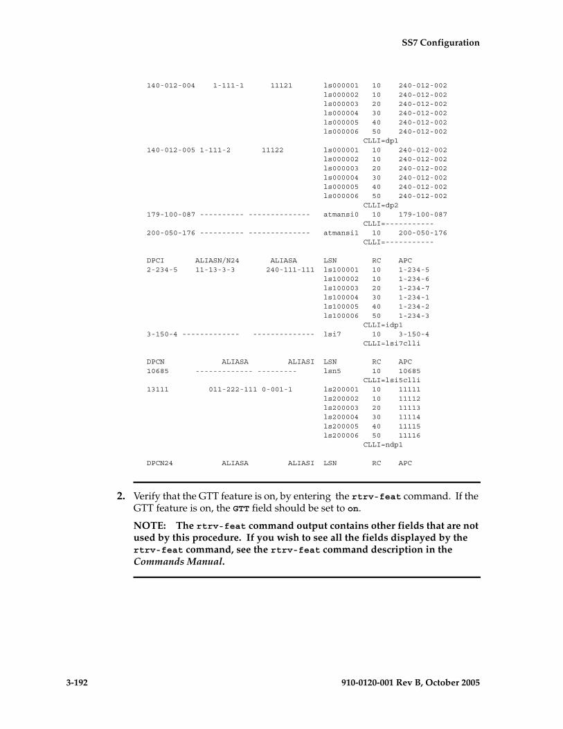
3-192 910-0120-001 Rev B, October 2005
SS7 Configuration
140-012-004 1-111-1 11121 ls000001 10 240-012-002 ls000002 10 240-012-002 ls000003 20 240-012-002 ls000004 30 240-012-002 ls000005 40 240-012-002 ls000006 50 240-012-002 CLLI=dp1 140-012-005 1-111-2 11122 ls000001 10 240-012-002 ls000002 10 240-012-002 ls000003 20 240-012-002 ls000004 30 240-012-002 ls000005 40 240-012-002 ls000006 50 240-012-002 CLLI=dp2 179-100-087 ---------- -------------- atmansi0 10 179-100-087 CLLI=----------- 200-050-176 ---------- -------------- atmansi1 10 200-050-176 CLLI=-----------
DPCI ALIASN/N24 ALIASA LSN RC APC 2-234-5 11-13-3-3 240-111-111 ls100001 10 1-234-5 ls100002 10 1-234-6 ls100003 20 1-234-7 ls100004 30 1-234-1 ls100005 40 1-234-2 ls100006 50 1-234-3 CLLI=idp1 3-150-4 ------------- -------------- lsi7 10 3-150-4 CLLI=lsi7clli
DPCN ALIASA ALIASI LSN RC APC 10685 ------------- --------- lsn5 10 10685 CLLI=lsi5clli 13111 011-222-111 0-001-1 ls200001 10 11111 ls200002 10 11112 ls200003 20 11113 ls200004 30 11114 ls200005 40 11115 ls200006 50 11116 CLLI=ndp1
DPCN24 ALIASA ALIASI LSN RC APC
2. Verify that the GTT feature is on, by entering the rtrv-feat command. If the GTT feature is on, the GTT field should be set to on.
NOTE: The rtrv-feat command output contains other fields that are not used by this procedure. If you wish to see all the fields displayed by the rtrv-feat command, see the rtrv-feat command description in the Commands Manual.
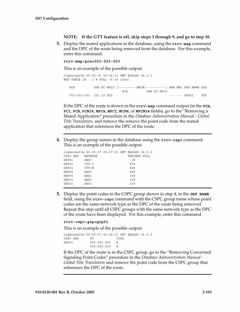
SS7 Configuration
910-0120-001 Rev B, October 2005 3-193
NOTE: If the GTT feature is off, skip steps 3 through 9, and go to step 10.
3. Display the mated applications in the database, using the rtrv-map command and the DPC of the route being removed from the database. For this example, enter this command.
rtrv-map:pca=003-003-003
This is an example of the possible output.
rlghncxa03w 05-09-07 00:34:31 GMT EAGLE5 34.0.0MAP TABLE IS 1 % FULL (5 of 1024)
PCA SSN RC MULT |----------MATE-----------| SRM MRC GRP NAME SSO PCA SSN RC MULT 003-003-003 252 10 SOL --- --- GRP01 OFF
If the DPC of the route is shown in the rtrv-map command output (in the PCA, PCI, PCN, PCN24, MPCA, MPCI, MCPN, or MPCN24 fields), go to the “Removing a Mated Application” procedure in the Database Administration Manual - Global Title Translation, and remove the remove the point code from the mated application that references the DPC of the route.
4. Display the group names in the database using the rtrv-cspc command. This is an example of the possible output.
rlghncxa03w 05-09-07 00:27:31 GMT EAGLE5 34.0.0CSPC GRP NETWORK PERCENT FULLGRP01 ANSI 3%GRP02 ITU-I 81%GRP03 ITU-N 54%GRP04 ANSI 42%GRP05 ANSI 15%GRP10 ANSI 15%GRP15 ANSI 15%
5. Display the point codes in the CSPC group shown in step 4, in the GRP NAME field, using the rtrv-cspc command with the CSPC group name whose point codes are the same network type as the DPC of the route being removed. Repeat this step until all CSPC groups with the same network type as the DPC of the route have been displayed. For this example, enter this command.
rtrv-cspc:grp=grp01
This is an example of the possible output.rlghncxa03w 05-09-07 00:28:31 GMT EAGLE5 34.0.0CSPC GRP PC TYPEGRP01 003-003-003 A 009-009-009 A
If the DPC of the route is in the CSPC group, go to the “Removing Concerned Signaling Point Codes” procedure in the Database Administration Manual - Global Title Translation and remove the point code from the CSPC group that references the DPC of the route.

3-194 910-0120-001 Rev B, October 2005
SS7 Configuration
6. Display the status of the Intermediate GTT Load Sharing (IGTTLS) controlled feature by entering this command.
rtrv-ctrl-feat:partnum=893006901
The following is an example of the possible output.
rlghncxa03w 05-09-28 21:15:37 GMT EAGLE5 34.0.0The following features have been permanently enabled:
Feature Name Partnum Status QuantityINTERMED GTT LOAD SHARING 893006901 off ----
The following features have been temporarily enabled:
Feature Name Partnum Status Quantity Trial Period LeftZero entries found.
The following features have expired temporary keys:
Feature Name PartnumZero entries found.
NOTE: If the IGTTLS feature is not enabled, skip steps 7 and 8, and go to step 9.
7. Display the mated relay node (MRN) groups in the database, using the rtrv-mrn command. This is an example of the possible output.rlghncxa03w 01-09-07 00:34:31 GMT EAGLE5 34.0.0 5-5-5
PC RC5-5-5 106-1-1 206-1-2 306-1-3 406-1-4 50
PC RC6-1-5 606-1-6 706-1-7 806-1-8 90
7-7-7
PC RC7-7-7 108-1-1 208-1-2 308-1-3 408-1-4 50
PC RC8-1-5 608-1-6 708-1-7 808-1-8 90

SS7 Configuration
910-0120-001 Rev B, October 2005 3-195
NOTE: If the DPC of the route is not shown in the rtrv-mrn output in step 8, skip this step and go to step 9.
8. Go to the “Removing an MRN Group or MRN Group Entry” procedure in the Database Administration Manual - Global Title Translation, and remove the remove the point code from the MRN group that references the DPC of the route.
NOTE: If the X.25 feature is off, skip steps 10 and 11, and go to step 12. If the DPC of the route is an ITU-I or ITU-N point code, skip steps 10, 11, 12, 13, and 14, and go to step 15.
9. Verify whether or not the DPC of the route is assigned to an X.25 destination by entering the rtrv-x25-dstn command. This is an example of the possible output.rlghncxa03w 05-09-28 21:16:37 EDT EAGLE5 34.0.0X25 ADDR SS7 DPC SSN11101 244-020-004 005220525586456772 244-020-005 00233301 244-020-006 006423423045656767 244-020-007 11255501 244-020-008 005X.25 DSTN TABLE IS 1 % FULL
If the X.25 DPC is assigned to an X.25 destination, go to step 8. Otherwise skip step 8, and go to step 9.
10. Verify whether or not the X.25 destination is assigned to an X.25 route by entering the rtrv-x25-rte command. This is an example of the possible output.rlghncxa03w 05-09-28 21:16:37 EDT EAGLE5 34.0.0X25 ADDR SS7 ADDR TYPE LOC PORT LC RT LC2NM11101 44401 pvc 1205 a 01 pc no220525586456772 342342341234567 pvc 1201 a 02 xpc yes33301 44401 svca 1207 a -- pc no33302 55501 svca 1207 a -- pc no423423045656767 34223422845 svca 1202 a -- pc noX.25 ROUTE TABLE IS 1 % FULL
If the rtrv-x25-rte command output shows X.25 routes using the X.25 destinations assigned to the DPC of the route being removed from the database, go to the “Removing an X.25 Route” procedure in the Database Administration Manual - Features to remove the X.25 routes that are using the X.25 destinations assigned to the DPC of the route.After the X.25 routes have been removed from the database, or if no X.25 routes are using the X.25 destinations assigned to the X.25 DPC, go to the “Removing an X.25 Gateway Destination” procedure in the Database Administration Manual - Features and remove the X.25 destinations assigned to the DPC from the database.

3-196 910-0120-001 Rev B, October 2005
SS7 Configuration
11. Verify whether or not the DPC of the route is referenced by the gateway screening redirect function by entering the rtrv-gws-redirect command. The following is an example of the possible output.
rlghncxa03w 05-09-07 00:17:31 GMT EAGLE5 34.0.0
ENABLED DPC RI SSN TT GTAon 003-003-003 GT 15 225 9105551212
If the DPC of the route is shown in the DPC field, go to the “Changing the Gateway Screening Redirect Parameters” procedure in the Database Administration Manual - Features and change the gateway screening redirect function’s DPC.
12. Verify whether or not the DPC of the route is a member of a cluster point code by entering the rtrv-dstn command with the value of the dpca parameter containing the network and cluster values of the DPC of the route, and three asterisks (***) for the network-cluster member value of the point code. For this example, enter this command.
rtrv-dstn:dpca=003-003-***
This is an example of the possible output.
rlghncxa03w 05-09-17 16:00:32 GMT EAGLE5 34.0.0 DPCA CLLI BEI ELEI ALIASI ALIASN/N24 DOMAIN 003-003-* rlghncbb333 yes no ---------- -------------- SS7 003-003-003 rlghncbb334 no --- 1-112-3 10-13-10-1 SS7 003-003-200 rlghncbb335 no --- 1-117-3 10-13-11-1 SS7 003-003-225 rlghncbb336 no --- ---------- -------------- SS7
SPC NCAI ----------- no
Destination table is (11 of 2000) 1% fullAlias table is (6 of 8000) 1% fullRTRV-DSTN: MASP A - COMPLTD
If the DPC of the route is not a member of a cluster point code, go to step 15.
If the DPC of the route is a member of a cluster point code, go to step 14.

SS7 Configuration
910-0120-001 Rev B, October 2005 3-197
13. Display the attributes of the cluster point code by entering the rtrv-dstn command with the cluster point code value. For this example, enter this command.
rtrv-dstn:dpca=003-003-*
This is an example of the possible output.
rlghncxa03w 05-09-28 21:16:37 GMT EAGLE5 34.0.0 DPCA CLLI BEI ELEI ALIASI ALIASN/N24 DOMAIN 003-003-* rlghncbb333 yes no ---------- -------------- SS7
SPC NCAI ----------- no
Destination table is (11 of 2000) 1% fullAlias table is (6 of 8000) 1% fullRTRV-DSTN: MASP A - COMPLTD
If the value of the NCAI field is yes, go to step 14.
If the value of the NCAI field is no, the route to the DPC (if the DPC is not a cluster point code) cannot be removed. To remove the route to this DPC, go to the “Changing the Attributes of a Cluster Point Code” procedure on page 2-161 and change the NCAI field value of the cluster point code to yes.
14. Remove the routes from the database using the dlt-rte command. For this example, enter this command.
dlt-rte:dpca=003-003-003:all=yes
A specific route to a DPC can be removed from the database. To do this, specify the lsn parameter instead of the all parameter and the linkset name of the route you wish to remove. For this example, enter this command.
dlt-rte:dpca=003-003-003:lsn=ls01
If the NCAI field value in step 14 is no, and was not changed, enter the dlt-rte command specifying the cluster point code as the value of the dpca parameter. For this example, enter this command.
dlt-rte:dpca=003-003-*:all=yes
When either of these commands have successfully completed, this message should appear.
rlghncxa03w 05-09-07 08:45:54 GMT EAGLE5 34.0.0DLT-RTE: MASP A - COMPLTD

3-198 910-0120-001 Rev B, October 2005
SS7 Configuration
15. Verify the changes using the rtrv-rte command, specifying the destination point code of the route. For this example, enter this command.
rtrv-rte:dpc=003-003-003
If all routes to the DPC were removed in step 14, this is an example of the possible output.
rlghncxa03w 05-09-10 11:43:04 GMT EAGLE5 34.0.0 DPCA ALIASI ALIASN/N24 LSN RC APCA 003-003-003 ---------- -------------- ---------- -- ----------- CLLI=ls03clli
If a specific route to the DPC was removed in step 14, this is an example of the possible output.rlghncxa03w 05-09-10 11:43:04 GMT EAGLE5 34.0.0 DPCA ALIASI ALIASN/N24 LSN RC APCA 003-003-003 ----------- ----------- ls03 10 003-003-003 ls02 30 004-004-004 CLLI=ls03clli
16. Back up the new changes using the chg-db:action=backup:dest=fixed command. These messages should appear, the active Maintenance and Administration Subsystem Processor (MASP) appears first.
BACKUP (FIXED) : MASP A - Backup starts on active MASP.BACKUP (FIXED) : MASP A - Backup on active MASP to fixed disk complete.BACKUP (FIXED) : MASP A - Backup starts on standby MASP.BACKUP (FIXED) : MASP A - Backup on standby MASP to fixed disk complete.
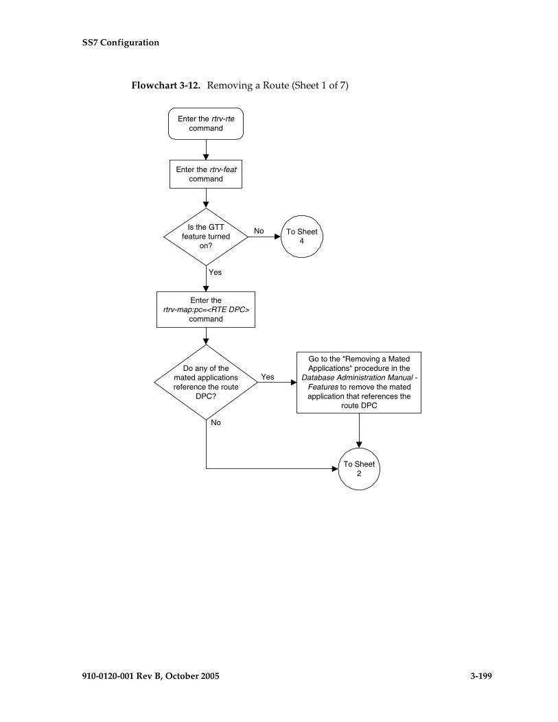
SS7 Configuration
910-0120-001 Rev B, October 2005 3-199
Flowchart 3-12. Removing a Route (Sheet 1 of 7)
Is the GTTfeature turned
on?
Enter thertrv-map:pc=<RTE DPC>
command
Enter the rtrv-featcommand
No
Yes
To Sheet4
Enter the rtrv-rtecommand
Do any of themated applicationsreference the route
DPC?
Go to the "Removing a MatedApplications" procedure in the
Database Administration Manual -Features to remove the matedapplication that references the
route DPC
Yes
No
To Sheet2
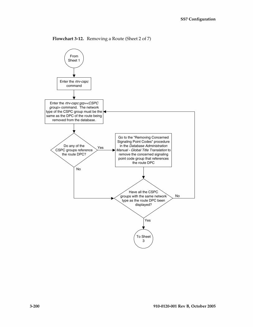
3-200 910-0120-001 Rev B, October 2005
SS7 Configuration
Flowchart 3-12. Removing a Route (Sheet 2 of 7)
To Sheet3
Enter the rtrv-cspc:grp=<CSPCgroup> command. The network
type of the CSPC group must be thesame as the DPC of the route being
removed from the database.
Do any of theCSPC groups reference
the route DPC?
Go to the "Removing ConcernedSignaling Point Codes" procedure
in the Database AdministrationManual - Global Title Translation to
remove the concerned signalingpoint code group that references
the route DPC
FromSheet 1
Enter the rtrv-cspccommand
Have all the CSPCgroups with the same networktype as the route DPC been
displayed?
No
Yes
No
Yes

SS7 Configuration
910-0120-001 Rev B, October 2005 3-201
Flowchart 3-12. Removing a Route (Sheet 3 of 7)
To Sheet4
FromSheet 2
Enter the rtrv-ctrl-featcommand
Enter thertrv-mrn command
Is the DPCin the mated relay
node table?
Go to the "Removing an MRNGroup or MRN Group Entry"procedure in the Database
Administration Manual - Global TitleTranslation and remove the DPC
from mated relay node table
Yes
No
Is the IGTTLSfeature enabled?
Is the status of theIGTTLS on or off?
Enter the chg-ctrl-feat:partnum=893006901:status=on command
Off
On
Yes
No

3-202 910-0120-001 Rev B, October 2005
SS7 Configuration
Flowchart 3-12. Removing a Route (Sheet 4 of 7)
Is the X.25feature on?
Enter the rtrv-x25-dstncommand
No
Yes
To Sheet6
Enter the rtrv-x25-rtecommand
Do any of theX.25 routes reference
the route DPC?
Go to the "Removing an X.25Route" procedure in the DatabaseAdministration Manual - Features
to remove the X.25 route thatreferences the route DPC
Yes
No
FromSheets 1
or 3
Do any of theX.25 destinations
reference the routeDPC?
Go to the "Removing an X.25Destination" procedure in the
Database Administration Manual -Features to remove the X.25
destination that references theroute DPC
Yes
No
Is the DPC ofthe route an ANSI
point code?
Yes
No
Does the gatewayscreening redirect
function DPC referencethe route DPC?
Enter the rtrv-gws-redirectcommand
No
Yes
Go to the "Changing the GatewayScreening Redirect Parameters"
procedure in the DatabaseAdministration Manual - Features andchange the gateway screening redirect
function point code
To Sheet5

SS7 Configuration
910-0120-001 Rev B, October 2005 3-203
Flowchart 3-12. Removing a Route (Sheet 5 of 7)
Enter thechg-db:action=backup:dest=fixed
command
FromSheet 4
Enter thedlt-rte command with the
all=yes parameter and with oneof these parameters
corresponding to the DPC of theroute being removed::dpci=<ITU-I DPC>
:dpcn=<14-bit ITU-N DPC>:dpcn24=<24-bit ITU-N DPC>
Enter thertrv-rte:dpc=<DPC value
specified in the dlt-rtecommand> command
Are all routes to theDPC to be removed?
No
Yes
Enter thedlt-rte command with thelsn=<LSN of RTE being
removed> parameter and withone of these parameters
corresponding to the DPC of theroute being removed::dpci=<ITU-I DPC>
:dpcn=<14-bit ITU-N DPC>:dpcn24=<24-bit ITU-N DPC>
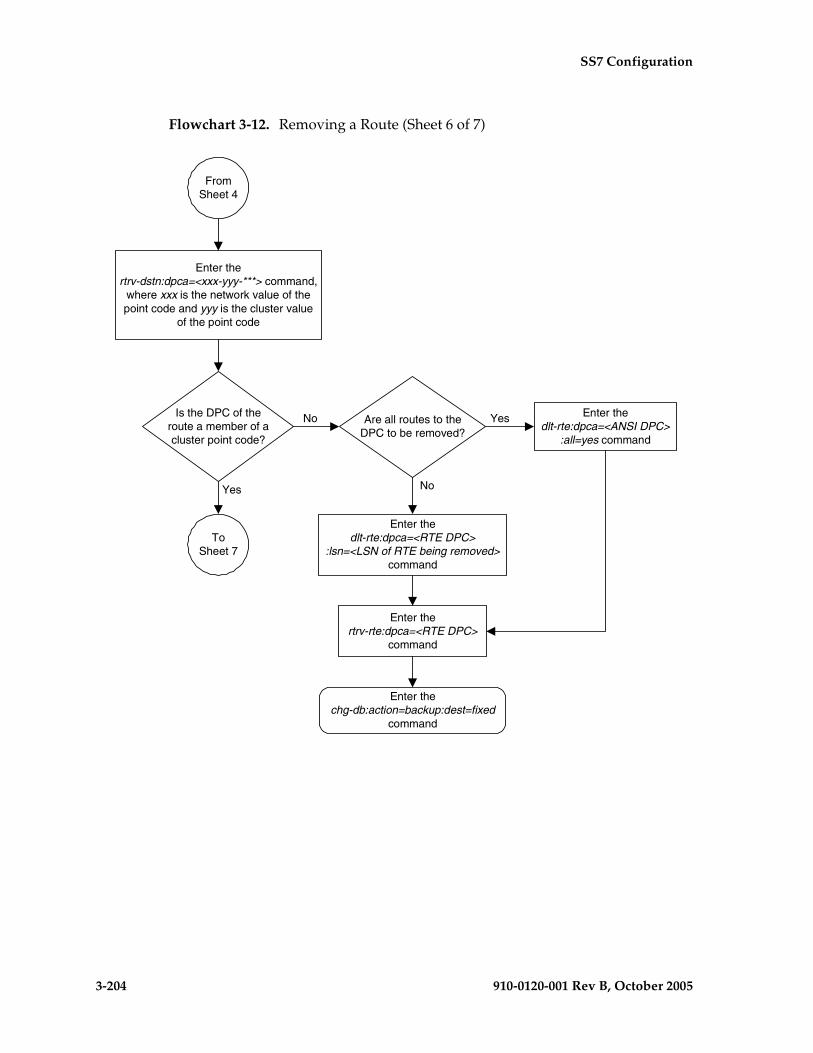
3-204 910-0120-001 Rev B, October 2005
SS7 Configuration
Flowchart 3-12. Removing a Route (Sheet 6 of 7)
Is the DPC of theroute a member of acluster point code?
Yes
No
FromSheet 4
Enter thertrv-dstn:dpca=<xxx-yyy-***> command,
where xxx is the network value of thepoint code and yyy is the cluster value
of the point code
Enter thertrv-rte:dpca=<RTE DPC>
command
Enter thechg-db:action=backup:dest=fixed
command
ToSheet 7
Enter thedlt-rte:dpca=<ANSI DPC>
:all=yes command
Are all routes to theDPC to be removed?
Enter thedlt-rte:dpca=<RTE DPC>
:lsn=<LSN of RTE being removed>command
No
Yes
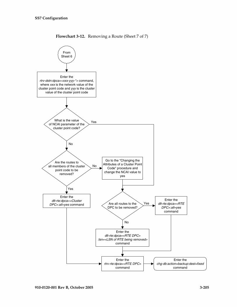
SS7 Configuration
910-0120-001 Rev B, October 2005 3-205
Flowchart 3-12. Removing a Route (Sheet 7 of 7)
FromSheet 6
What is the valueof NCAI parameter of the
cluster point code?
Enter thertrv-dstn:dpca=<xxx-yyy-*> command,where xxx is the network value of the
cluster point code and yyy is the clustervalue of the cluster point code
Yes
No
Enter thedlt-rte:dpca=<RTE
DPC>:all=yescommand
Are all routes to theDPC to be removed?
Enter thedlt-rte:dpca=<RTE DPC>
:lsn=<LSN of RTE being removed>command
No
Yes
Are the routes toall members of the cluster
point code to beremoved?
Go to the "Changing theAttributes of a Cluster Point
Code" procedure andchange the NCAI value to
yes
Enter thedlt-rte:dpca=<Cluster
DPC>:all=yes command
Enter thertrv-rte:dpca=<RTE DPC>
command
Enter thechg-db:action=backup:dest=fixed
command
No
Yes

3-206 910-0120-001 Rev B, October 2005
SS7 Configuration
Changing a Route
This procedure is used to change the relative cost of a route in the database using the chg-rte command.
The chg-rte command uses these parameters.
:dpc/dpca/dpci/dpcn/dpcn24 – The destination point code of the node that the traffic is bound for.
NOTE: See “Point Code Formats” on page 2-4 for a definition of the point code types that are used on the EAGLE 5 SAS and for a definition of the different formats that can be used for ITU national point codes.
:lsn – The name of the linkset that will carry the traffic bound for the node specified by the destination point code.
:rc – The relative cost (priority) for this route.
:nlsn – The name of the new linkset that will carry the traffic bound for the node specified by the destination point code.
The route to be changed must exist in the database. This can be verified in step 1.
A maximum of two linksets can be assigned the same cost. The cost of the route is defined by the rc parameter of the chg-rte command and is shown in the RC field in the output of the rtrv-rte command.
The linkset name specified by the lsn parameter must be defined in the database as a route.
The examples in this procedure are used to change the relative cost assigned to the linkset ls01 for the route to DPC 003-003-003 in the database to change the name of linkset ls01 to lsa2.
If the destination of a route (DPC/DPCA) is in the X.25 domain, no routes to that destination can be assigned the same cost value (RC) in the same routeset. If two routes in a routeset were assigned the same cost value, this creates a combined linkset and combined linksets to DPCs in the X.25 domain are not allowed.
The ANSI DPC (DPC/DPCA) of the route can use either a full point code, a cluster point code, or a network routing point code. ITU DPCs (DPCI and DPCN - 14-bit or 24-bit DPCNs) must use full point codes. For more information on full and cluster point codes, go to the“Cluster Routing and Management Diversity (CRMD)” section on page 2-119. For more information on network routing point codes, go to the “Network Routing” section on page 2-174.

SS7 Configuration
910-0120-001 Rev B, October 2005 3-207
The DPC of the route must be of the same format as the APC of the linkset being added to the route. That is, routes containing ANSI DPCs must have linksets with ANSI APCs; routes containing ITU-I DPCs must have linksets with ITU-I APCs; routes containing 14-bit ITU-N DPCs must have linksets with 14-bit ITU-N APCs; routes containing 24-bit ITU-N DPCs must have linksets with 24-bit ITU-N APCs. The DPC of the route must be defined as a true point code in the rtrv-dstn output. Alias point codes and secondary point codes cannot be used. True point codes are shown in the output of the rtrv-dstn command in the DPCA, DPCI, DPCN, or DPCN24 fields.
Either the nlsn or rc parameters, or both, must be specified with the chg-rte command. If neither of these parameters are specified, the command is rejected.
The new linkset specified by the nlsn parameter cannot be assigned to any existing routes. If the new linkset is assigned to any existing routes, the command is rejected. This can be verified with the rtrv-rte command.
The linkset specified by the nlsn parameter must be in the database and must contain at least one signaling link. This can be verified with the rtrv-ls command and specifying the name of the linkset with the lsn parameter.
If the DPC of the route is a cluster point code, only linksets, specified with either the lsn or nlsn parameters, whose linkset type is either B, C, or D can be assigned to the route. The linkset type is shown in the LST field of the rtrv-ls command output. If the linkset type of the desired linkset is either A or E, one of three actions must be taken.
• Choose another linkset with the linkset type B, C, or D.
• Change the linkset type of an existing linkset – go to the “Changing an SS7 Linkset” procedure on page 3-74.
• Add a new linkset to the database with the necessary signaling links and the linkset type B, C, or D.
a. Go to the “Adding an SS7 Linkset” procedure on page 3-17 to add the linkset.
b. If the necessary signaling links are not in the database, go to the “Adding an SS7 Signaling Link” procedure on page 3-130 and add the signaling links to the database.
If the DPC of the route is a private point code, the new linkset specified for the route being changed must be an IPGWx linkset (a linkset containing the ipgwapc=yes parameter value).
3-208 910-0120-001 Rev B, October 2005
SS7 Configuration
If the DPC of the route is a member of a cluster point code, and the nested cluster allowed indicator (ncai parameter of either the ent-dstn or chg-dstn command) is set to no, then all destinations in the cluster have the same route as the cluster point code, with the same attributes as the route to the cluster point code. If the nested cluster allowed indicator is set to yes, then the routes to the members of the cluster point code, and the attributes of these routes, can be different from the route to the cluster point code. For more information, see the “Nested Cluster Routing” section on page 2-135.
For routes containing 14-bit ITU National DPCs with group codes, if the linkset assigned to the route has the MULTGC value set to yes, then 14-bit ITU National DPCs with group codes that are different from the linkset APC group code can be assigned to the route. If the MULTGC value is set to no, then only 14-bit ITU National DPCs with group codes that are the same as the linkset APC group code can be assigned to the route.
Canceling the RTRV-LS and RTRV-RTE Commands
Because the rtrv-ls and rtrv-rte commands used in this procedure can output information for a long period of time, the rtrv-ls and rtrv-rte commands can be canceled and the output to the terminal stopped. There are three ways that the rtrv-ls and rtrv-rte commands can be canceled.
• Press the F9 function key on the keyboard at the terminal where the rtrv-ls or rtrv-rte commands were entered.
• Enter the canc-cmd without the trm parameter at the terminal where the rtrv-ls or rtrv-rte commands were entered.
• Enter the canc-cmd:trm=<xx>, where <xx> is the terminal where the rtrv-ls or rtrv-rte commands were entered, from another terminal other that the terminal where the rtrv-ls or rtrv-rte commands were entered. To enter the canc-cmd:trm=<xx> command, the terminal must allow Security Administration commands to be entered from it and the user must be allowed to enter Security Administration commands. The terminal’s permissions can be verified with the rtrv-secu-trm command. The user’s permissions can be verified with the rtrv-user or rtrv-secu-user commands.
For more information about the canc-cmd command, go to the Commands Manual.
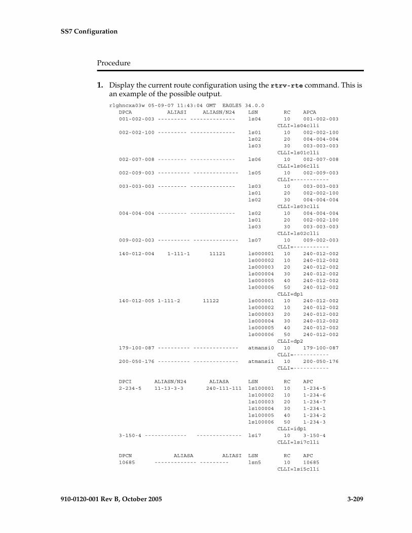
SS7 Configuration
910-0120-001 Rev B, October 2005 3-209
Procedure
1. Display the current route configuration using the rtrv-rte command. This is an example of the possible output.rlghncxa03w 05-09-07 11:43:04 GMT EAGLE5 34.0.0 DPCA ALIASI ALIASN/N24 LSN RC APCA 001-002-003 --------- -------------- ls04 10 001-002-003 CLLI=ls04clli 002-002-100 --------- -------------- ls01 10 002-002-100 ls02 20 004-004-004 ls03 30 003-003-003 CLLI=ls01clli 002-007-008 --------- -------------- ls06 10 002-007-008 CLLI=ls06clli 002-009-003 ---------- -------------- ls05 10 002-009-003 CLLI=----------- 003-003-003 --------- -------------- ls03 10 003-003-003 ls01 20 002-002-100 ls02 30 004-004-004 CLLI=ls03clli 004-004-004 --------- -------------- ls02 10 004-004-004 ls01 20 002-002-100 ls03 30 003-003-003 CLLI=ls02clli 009-002-003 ---------- -------------- ls07 10 009-002-003 CLLI=----------- 140-012-004 1-111-1 11121 ls000001 10 240-012-002 ls000002 10 240-012-002 ls000003 20 240-012-002 ls000004 30 240-012-002 ls000005 40 240-012-002 ls000006 50 240-012-002 CLLI=dp1 140-012-005 1-111-2 11122 ls000001 10 240-012-002 ls000002 10 240-012-002 ls000003 20 240-012-002 ls000004 30 240-012-002 ls000005 40 240-012-002 ls000006 50 240-012-002 CLLI=dp2 179-100-087 ---------- -------------- atmansi0 10 179-100-087 CLLI=----------- 200-050-176 ---------- -------------- atmansi1 10 200-050-176 CLLI=-----------
DPCI ALIASN/N24 ALIASA LSN RC APC 2-234-5 11-13-3-3 240-111-111 ls100001 10 1-234-5 ls100002 10 1-234-6 ls100003 20 1-234-7 ls100004 30 1-234-1 ls100005 40 1-234-2 ls100006 50 1-234-3 CLLI=idp1 3-150-4 ------------- -------------- lsi7 10 3-150-4 CLLI=lsi7clli
DPCN ALIASA ALIASI LSN RC APC 10685 ------------- --------- lsn5 10 10685 CLLI=lsi5clli
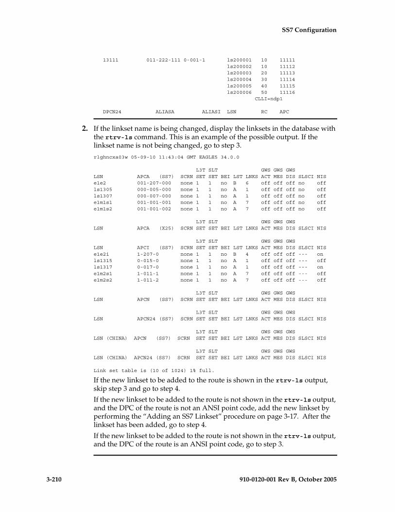
3-210 910-0120-001 Rev B, October 2005
SS7 Configuration
13111 011-222-111 0-001-1 ls200001 10 11111 ls200002 10 11112 ls200003 20 11113 ls200004 30 11114 ls200005 40 11115 ls200006 50 11116 CLLI=ndp1
DPCN24 ALIASA ALIASI LSN RC APC
2. If the linkset name is being changed, display the linksets in the database with the rtrv-ls command. This is an example of the possible output. If the linkset name is not being changed, go to step 3.
rlghncxa03w 05-09-10 11:43:04 GMT EAGLE5 34.0.0
L3T SLT GWS GWS GWSLSN APCA (SS7) SCRN SET SET BEI LST LNKS ACT MES DIS SLSCI NISe1e2 001-207-000 none 1 1 no B 6 off off off no offls1305 000-005-000 none 1 1 no A 1 off off off no offls1307 000-007-000 none 1 1 no A 1 off off off no offe1m1s1 001-001-001 none 1 1 no A 7 off off off no offe1m1s2 001-001-002 none 1 1 no A 7 off off off no off
L3T SLT GWS GWS GWSLSN APCA (X25) SCRN SET SET BEI LST LNKS ACT MES DIS SLSCI NIS
L3T SLT GWS GWS GWSLSN APCI (SS7) SCRN SET SET BEI LST LNKS ACT MES DIS SLSCI NISe1e2i 1-207-0 none 1 1 no B 4 off off off --- onls1315 0-015-0 none 1 1 no A 1 off off off --- offls1317 0-017-0 none 1 1 no A 1 off off off --- one1m2s1 1-011-1 none 1 1 no A 7 off off off --- offe1m2s2 1-011-2 none 1 1 no A 7 off off off --- off
L3T SLT GWS GWS GWSLSN APCN (SS7) SCRN SET SET BEI LST LNKS ACT MES DIS SLSCI NIS
L3T SLT GWS GWS GWSLSN APCN24 (SS7) SCRN SET SET BEI LST LNKS ACT MES DIS SLSCI NIS
L3T SLT GWS GWS GWSLSN (CHINA) APCN (SS7) SCRN SET SET BEI LST LNKS ACT MES DIS SLSCI NIS
L3T SLT GWS GWS GWSLSN (CHINA) APCN24 (SS7) SCRN SET SET BEI LST LNKS ACT MES DIS SLSCI NIS
Link set table is (10 of 1024) 1% full.
If the new linkset to be added to the route is shown in the rtrv-ls output, skip step 3 and go to step 4.
If the new linkset to be added to the route is not shown in the rtrv-ls output, and the DPC of the route is not an ANSI point code, add the new linkset by performing the “Adding an SS7 Linkset” procedure on page 3-17. After the linkset has been added, go to step 4.
If the new linkset to be added to the route is not shown in the rtrv-ls output, and the DPC of the route is an ANSI point code, go to step 3.

SS7 Configuration
910-0120-001 Rev B, October 2005 3-211
3. The ANSI DPC of the route can be either an SS7 or X.25 point code. Verify the domain of the ANSI DPC (SS7 or X.25) by entering the rtrv-dstn command with the DPC of the route. For this example, enter this command.
rtrv-dstn:dpca=003-003-003
This is an example of the possible output.
rlghncxa03w 05-09-28 21:16:37 GMT EAGLE5 34.0.0 DPCA CLLI BEI ELEI ALIASI ALIASN/N24 DOMAIN 003-003-003 ----------- yes no ---------- -------------- SS7
SPC NCAI ----------- no
Destination table is (12 of 2000) 1% fullAlias table is (6 of 8000) 1% fullRTRV-DSTN: MASP A - COMPLTD
If the domain of the point code is SS7, add the new linkset by performing the “Adding an SS7 Linkset” procedure on page 3-17.
If the domain of the point code is X.25, add the new linkset by performing the “Adding an X.25 Linkset” procedure in the Database Administration Manual - Features.
NOTE: If the DPC of the route is not a cluster point code, skip step 4 and go to step 5.
4. Display the ncai parameter value assigned to the cluster point code using the rtrv-dstn command and specifying the cluster point code. If the ncai parameter value is no, then the route to the DPC must be the same as the route to the cluster point code. If the ncai parameter value is yes, the route to the member of the cluster does not have to be the same as the route to the cluster point code. The ncai value is shown in the NCAI field of the rtrv-dstn output. For this example, enter this command.
rtrv-dstn:dpca=111-011-*
This is an example of the possible output.
rlghncxa03w 05-09-28 21:16:37 GMT EAGLE5 34.0.0 DPCA CLLI BEI ELEI ALIASI ALIASN/N24 DOMAIN 111-011-* rlghncbb000 yes yes ---------- -------------- SS7
SPC NCAI ----------- yes
Destination table is (12 of 2000) 1% fullAlias table is (6 of 8000) 1% fullRTRV-DSTN: MASP A - COMPLTD

3-212 910-0120-001 Rev B, October 2005
SS7 Configuration
NOTE: If the DPC of the route is not a cluster point code, a 14-bit ITU-N point code with group codes, or a private point code, skip this step and go to step 6.
5. Display each linkset being assigned to the route to verify the multgc and ipgwapc parameter values with the rtrv-ls command, specifying the name of the linkset that will be assigned to the route.
If the multgc linkset parameter value is yes, then 14-bit ITU National DPCs with group codes that are different from the linkset APC group code can be assigned to the route. If the multgc value is set to no, then only 14-bit ITU National DPCs with group codes that are the same as the linkset APC group code can be assigned to the route. The multgc value is shown in the MULTGC field of the rtrv-ls output.
The ipgwapc linkset parameter value is yes, the DPC of the route cannot be a cluster point code. The ipgwapc value is shown in the IPGWAPC field of the rtrv-ls output.
If the DPC of the route is a private point code, the new linkset specified for the route being changed must be an IPGWx linkset (a linkset containing the ipgwapc=yes parameter value).
For this example, enter the following commands.
rtrv-ls:lsn=ls1317
This is an example of the possible output.
rlghncxa03w 05-09-17 11:43:04 GMT EAGLE5 34.0.0
L3T SLT GWS GWS GWSLSN APCI (SS7) SCRN SET SET BEI LST LNKS ACT MES DIS SLSCI NISls1317 0-017-0 none 1 1 no A 1 off off off --- on
CLLI TFATCABMLQ MTPRSE ASL8 SLSRSB ITUTFR IPGWAPC ----------- 1 no --- 1 off yes
L2T L1 PCR PCR LOC LINK SLC TYPE SET BPS MODE TSET ECM N1 N2 1317 A 0 IPGWI
LP ATM LOC LINK SLC TYPE SET BPS TSEL VCI VPI LL
LP ATM E1ATM LOC LINK SLC TYPE SET BPS TSEL VCI VPI CRC4 SI SN
LOC LINK SLC TYPE IPLIML2
LOC LINK SLC TYPE
L2T PCR PCR E1 E1 LOC LINK SLC TYPE SET BPS ECM N1 N2 LOC PORT TS
L2T PCR PCR T1 T1 LOC LINK SLC TYPE SET BPS ECM N1 N2 LOC PORT TS
SAPCN 00136
Link set table is (10 of 1024) 1% full.
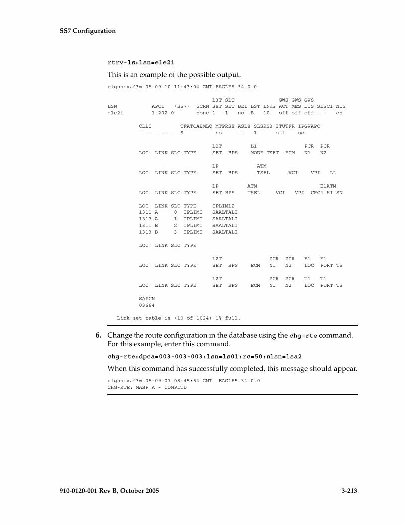
SS7 Configuration
910-0120-001 Rev B, October 2005 3-213
rtrv-ls:lsn=e1e2i
This is an example of the possible output.
rlghncxa03w 05-09-10 11:43:04 GMT EAGLE5 34.0.0
L3T SLT GWS GWS GWSLSN APCI (SS7) SCRN SET SET BEI LST LNKS ACT MES DIS SLSCI NISe1e2i 1-202-0 none 1 1 no B 10 off off off --- on
CLLI TFATCABMLQ MTPRSE ASL8 SLSRSB ITUTFR IPGWAPC ----------- 5 no --- 1 off no
L2T L1 PCR PCR LOC LINK SLC TYPE SET BPS MODE TSET ECM N1 N2
LP ATM LOC LINK SLC TYPE SET BPS TSEL VCI VPI LL
LP ATM E1ATM LOC LINK SLC TYPE SET BPS TSEL VCI VPI CRC4 SI SN
LOC LINK SLC TYPE IPLIML2 1311 A 0 IPLIMI SAALTALI 1313 A 1 IPLIMI SAALTALI 1311 B 2 IPLIMI SAALTALI 1313 B 3 IPLIMI SAALTALI
LOC LINK SLC TYPE
L2T PCR PCR E1 E1 LOC LINK SLC TYPE SET BPS ECM N1 N2 LOC PORT TS
L2T PCR PCR T1 T1 LOC LINK SLC TYPE SET BPS ECM N1 N2 LOC PORT TS
SAPCN 03664
Link set table is (10 of 1024) 1% full.
6. Change the route configuration in the database using the chg-rte command. For this example, enter this command.
chg-rte:dpca=003-003-003:lsn=ls01:rc=50:nlsn=lsa2
When this command has successfully completed, this message should appear.
rlghncxa03w 05-09-07 08:45:54 GMT EAGLE5 34.0.0CHG-RTE: MASP A - COMPLTD
3-214 910-0120-001 Rev B, October 2005
SS7 Configuration
7. Verify the changes using the rtrv-rte command, specifying the destination point code of the route. For this example, enter this command.
rtrv-rte:dpca=003-003-003
This is an example of the possible output.
rlghncxa03w 05-09-07 11:43:04 GMT EAGLE5 34.0.0 DPCA ALIASI ALIASN/N24 LSN RC APCA 003-003-003 ---------- -------------- ls03 10 003-003-003 ls01 20 002-002-100 ls02 30 004-004-004 CLLI=ls03clli
8. Back up the new changes using the chg-db:action=backup:dest=fixed command. These messages should appear, the active Maintenance and Administration Subsystem Processor (MASP) appears first.
BACKUP (FIXED) : MASP A - Backup starts on active MASP.BACKUP (FIXED) : MASP A - Backup on active MASP to fixed disk complete.BACKUP (FIXED) : MASP A - Backup starts on standby MASP.BACKUP (FIXED) : MASP A - Backup on standby MASP to fixed disk complete.

SS7 Configuration
910-0120-001 Rev B, October 2005 3-215
Flowchart 3-13. Changing a Route (Sheet 1 of 4)
Enter the rtrv-lscommand
Is the desiredlinkset in the database?
(See Note 3 onSheet 4)
Yes
No
Go to the "Adding an SS7Linkset" procedure and
add the SS7 linkset to thedatabase
Is the domain ofthe DPC of the route
SS7 or X.25?
Go to the "Adding an X.25 Linkset"procedure in the Database
Administration Manual - Featuresand add the X.25 linkset to the
database
SS7
X.25
Enter the rtrv-rtecommand
ToSheet 2
Is the linksetname to bechanged?
Is the DPC of theroute an ANSI DPC?
Yes
No
Yes
No
Enter the chg-rte command with theseparameters:
:lsn = <linkset name>:dpc/dpca/dpci/dpcn/dpcn24 =
<destination point code of the route>:rc = <0 - 99>
(See Notes 1 and 2 on Sheet 3)
Enter the rtrv-rte:dpc=<DPC ofthe route specified in the
chg-rte command> command
Enter thechg-db:action=backup:dest=fixed
command
ToSheet 2
Enter the rtrv-dstncommand with this
parameter::dpc/dpca=<DPC of
the route>

3-216 910-0120-001 Rev B, October 2005
SS7 Configuration
Flowchart 3-13. Changing a Route (Sheet 2 of 4)
FromSheet 1
Enter the rtrv-ls command with thisparameter:
:lsn=<name of the new linkset beingassigned to the route>
If the DPC of the route is both a 14-bit ITU-Npoint code and a private point code, verifythe MULTGC and IPGWAPC values in the
linkset displayed in this step.
Is the DPC of theroute a cluster point
code?
Yes
No
Is the DPC ofthe route a 14-bit
ITU-N point code with groupcodes? (see Note 6 on
Sheet 4)
Enter the rtrv-dstn command withthis parameter:
:dpc/dpca=<cluster DPC of theroute>
Yes
NoIs the DPC of
the route a privatepoint code? (See Note
4 on Sheet 4)
No
Yes
ToSheet 3
Was the previousstep performed to only
check the MULTGC valueof the linkset?
If the DPC ofthe route is a private
point code, what is theIPGWAPC value of the
linkset?
Yes
No No
Yes
Go to the “Configuring anIPGWx Linkset”procedure in the
Database AdministrationManual - IP7 Secure
Gateway and configurean IPGWx linkset toassign to the route
ToSheet 3

SS7 Configuration
910-0120-001 Rev B, October 2005 3-217
Flowchart 3-13. Changing a Route (Sheet 3 of 4)
Enter the chg-rte command with thesemandatory parameters::lsn = <linkset name>
:dpc/dpca/dpci/dpcn/dpcn24 =<destination point code of the route>
and at least one of these optionalparameters:
:rc = <0 - 99>:nlsn = <new linkset name>
(See Notes 1 through 8 on Sheet 4)
Enter the rtrv-rte command with thisparameter:
:dpc/dpca/dpci/dpcn/dpcn24=<DPCof the route specified in the
chg-rte command>
Enter thechg-db:action=backup:dest=fixed
command
FromSheet 2

3-218 910-0120-001 Rev B, October 2005
SS7 Configuration
Flowchart 3-13. Changing a Route (Sheet 4 of 4)
Notes:
1. For an SS7 route, a maximum of two linksets can be assigned the same rc parameter value.
2. For an X.25 route, the rc parameter values for all linksets cannot be equal.
3. If the DPC of the route is a cluster point code, the link set type of the linkset assigned to theroute must be either B, C, or D.
4. If the DPC of the route is a private point code, the ipgwapc value of the new linkset must beyes.
5. If the DPC of the route is a member of a cluster point code, and the nested cluster allowedindicator (ncai parameter of either the ent-dstn or chg-dstn command) is set to no, then the routeto the DPC must be the same as the route to the cluster point code. If the nested cluster allowedindicator is set to yes, the route to the member of the cluster does not have to be the same asthe route to the cluster point code.
6. For routes containing 14-bit ITU National DPCs with group codes, if the linkset assigned to theroute has the MULTGC value set to yes, then the group code of the linkset's APC can bedifferent from the group code of the route's DPC. If the MULTGC value is set to no, then thegroup code of the linkset's APC must be the same as the group code of the route's DPC.
7. If the DPC of the route is a cluster point code, the linksets that will be assigned to the route,with the nlsn parameter, cannot specify the ipgwapc=yes parameter.
8. The DPC of the route must be of the same format as the APC of the linkset being added tothe route. That is, routes containing ANSI DPCs must have linksets with ANSI APCs; routescontaining ITU-I DPCs must have linksets with ITU-I APCs; routes containing 14-bit ITU-N DPCsmust have linksets with 14-bit ITU-N APCs; routes containing 24-bit ITU-N DPCs must havelinksets with 24-bit ITU-N APCs.

SS7 Configuration
910-0120-001 Rev B, October 2005 3-219
Changing Level 2 Timers
This procedure is used to change the values of a level 2 timer set using the chg-l2t command.
The l2tset parameter specifies the level 2 timer set that is being changed. The EAGLE 5 SAS contains 30 level 2 timer sets that signaling links can be assigned to. Level 2 timer sets are assigned to different types of signaling links as shown in Table 3-12.
Each level 2 timer set contains seven timers. Table 3-13 defines the timers and their values.
Table 3-12. Level 2 Timer Sets
Level 2 Timer Set (l2tset Parameter Value)
Type of Signaling Link
1 - 10 Low-speed ANSI signaling links
11 - 20 Low-speed ITU signaling links
21 - 25 ITU-N high-speed signaling links for China
26 - 30 ITU-N high-speed signaling links for areas other than China
Table 3-13. Level 2 Timer Values
Level 2 Timers Level 2 Timer Sets 1 - 10 (in
milliseconds)
Level 2 Timer Sets 11 - 20 (in
milliseconds)
Level 2 Timer Sets 21 - 25 (in
milliseconds)
Level 2 Timer Sets 26 - 30 (in
milliseconds)
Timer 1 – Aligned ready (t1 parameter)
5000 - 20000System Default - 13000
40000 - 50000System Default - 40000
25000 - 350000System Default - 150000
25000 - 350000System Default - 150000
Timer 2 – Not aligned (t2 parameter)
5000 - 30000System Default - 11500
5000 - 150000System Default - 30000
5000 - 150000System Default - 130000
5000 - 150000System Default - 130000
Timer 3 – Aligned (t3 parameter)
5000 - 20000System Default - 11500
1000 - 2000System Default - 2000
1000 - 2000System Default - 1000
1000 - 2000System Default - 1000
Timer 4 – Normal proving period (t4npp parameter)
500 - 5000System Default - 2300
7500 - 9500System Default - 8200
3000 - 70000System Default - 30000
3000 - 70000System Default - 30000
Timer 4 – Emergency proving period (t4epp parameter)
200 - 1000System Default - 600
400 - 600System Default - 500
400 - 600System Default - 500
400 - 600System Default - 500
Timer 5 – Sending SIB (t5 parameter)
40 - 500System Default - 100
80 - 120System Default - 100
80 - 120System Default - 100
80 - 120System Default - 100
Timer 6 – Remote congestion (t6 parameter)
1000 - 10000System Default - 4000
3000 - 6000System Default - 4000
3000 - 6000System Default - 5000
3000 - 6000System Default - 5000
Timer 7 – Excessive delay of acknowledgment (t7 parameter)
200 - 3000System Default - 1500
500 - 2000System Default - 1500
500 - 2000System Default - 800
500 - 2000System Default - 800

3-220 910-0120-001 Rev B, October 2005
SS7 Configuration
The examples in this procedure are used to change the values of the level 2 timer set number 2.
Procedure
1. Display the values of the level 2 timer set you wish to change. Use the rtrv-l2t command, specifying the level 2 timer set to be changed. For this example, enter this command.
rtrv-l2t:l2tset=2
NOTE: Timer sets are individual sets of timer configurations; each link is assigned one of these timer sets. This allows different links to have different level 2 timer settings. This is an example of the possible output.rlghncxa03w 05-09-07 08:39:46 GMT EAGLE5 34.0.0L2T TIMERS (IN SECONDS)L2TSET T1 T2 T3 T4NPP T4EPP T5 T6 T72 10.0 20.0 20.0 5.0 1.00 0.50 10.0 3.0
2. Change the values of the level 2 timer in this set using the chg-l2t command. Refer to Table 3-13 on page 3-219 for the values that can be used with the chg-l2t command. For this example, the values of the level 2 timer set number 2 that are being changed are T2 and T6. To change these two values, enter this command.
chg-l2t:l2tset=2:t2=15000:t6=5000
When this command has successfully completed, this message should appear.
rlghncxa03w 05-09-07 08:39:36 GMT EAGLE5 34.0.0CHG-L2T: MASP A - COMPLTD
3. Verify the changes using the rtrv-l2t command, specifying the level 2 timer set that has been changed. For this example, enter this command.
rtrv-l2t:l2tset=2
This is an example of the possible output.
rlghncxa03w 05-09-07 08:39:46 GMT EAGLE5 34.0.0L2T TIMERS (IN SECONDS)L2TSET T1 T2 T3 T4NPP T4EPP T5 T6 T72 10.0 15.0 20.0 5.0 1.00 0.50 5.0 3.0
4. Back up the new changes using the chg-db:action=backup:dest=fixed command. These messages should appear, the active Maintenance and Administration Subsystem Processor (MASP) appears first.
BACKUP (FIXED) : MASP A - Backup starts on active MASP.BACKUP (FIXED) : MASP A - Backup on active MASP to fixed disk complete.BACKUP (FIXED) : MASP A - Backup starts on standby MASP.BACKUP (FIXED) : MASP A - Backup on standby MASP to fixed disk complete.

SS7 Configuration
910-0120-001 Rev B, October 2005 3-221
Flowchart 3-14. Changing the Level 2 Timers
3-222 910-0120-001 Rev B, October 2005
SS7 Configuration
Changing Level 3 Timers
This procedure is used to change the values of the level 3 timers using the chg-l3t command. The level 3 timers apply to both ANSI and ITU linksets, except as noted for the specific timer.
NOTE: Only one level 3 timer set exists.
The level 3 timers are defined as follows:
:t1 – Timer 1 – Delay to avoid message mis-sequencing on changeover. Values - 100-2000 milliseconds; system default value - 800 milliseconds.
:t2 – Timer 2 – Waiting for changeover acknowledgment. Values - 100-3000 milliseconds; system default value - 1400 milliseconds.
:t3 – Timer 3 – Time controlled diversion – delay to avoid mis-sequencing on changeback. Values - 100 - 2000 milliseconds; system default value - 800 milliseconds.
:t4 – Timer 4 – Waiting for changeback acknowledgment (1st attempt). Values - 100-2000 milliseconds; system default value - 800 milliseconds.
:t5 – Timer 5 – Waiting for changeback acknowledgment (2nd attempt). Values - 100-2000 milliseconds; system default value - 800 milliseconds.
:t6 – Timer 6 – Delay to avoid message mis-sequencing on controlled rerouting. Values - 100-2000 milliseconds; system default values - 800 milliseconds.
:t7 – Timer 7 – Waiting for signaling data link connection acknowledgment. Values - 100-3000 milliseconds; system default value - 1000 milliseconds.
:t8 – Timer 8 – Transfer-prohibited (TFP) inhibited timer (transient solution). Values - 500-2000 milliseconds; system default value - 800 milliseconds.
:t10 – Timer 10 – Waiting to repeat signaling-route-set-test (SRST) message. Values - 20000-90000 milliseconds; system default value - 30000 milliseconds.
:t11 – Timer 11 – Transfer-restricted timer. Values - 1000-90000 milliseconds; system default - 30000 milliseconds.
:t12 – Timer 12 – Waiting for uninhibit acknowledgment. Values - 100-2000 milliseconds; system default value - 800 milliseconds.
:t13 – Timer 13 – Waiting for force uninhibit. Values - 100-2000 milliseconds; system default value - 800 milliseconds.
:t14 – Timer 14 – Waiting for inhibition acknowledgment. Values - 200-4000 milliseconds; system default value - 2000 milliseconds.
:t15 – Timer 15 – Waiting to repeat signaling route set congestion test (RSCT). Values - 200-4000 milliseconds; system default value - 3000 milliseconds.
:t16 – Timer 16 – Waiting for route set congestion (RSC) status update. Values - 200-3000 milliseconds; system default value - 1400 milliseconds.
SS7 Configuration
910-0120-001 Rev B, October 2005 3-223
:t17 – Timer 17 – Delay to avoid oscillation of initial alignment failure and link restart. Values - 500-2000 milliseconds; system default value - 800 milliseconds.
:t18 – Timer 18 – ANSI linksets – Repeat TFR once by response method. Values - 2000-20000 milliseconds; system default value - 10000 milliseconds.
:it18 – Timer 18 – ITU linksets – Timer within a signaling point whose MTP restarts to supervise the receipt of routing information and activation of the link and linkset. Values - 19000-50000 milliseconds; system default value - 50000 milliseconds.
:t19 – Timer 19 – ANSI linksets – Failed link craft referral timer. Values - 30000-600000 milliseconds; system default value - 480000 milliseconds.
:it19 – Timer 19 – ITU linksets – Supervision timer during MTP restart to avoid ping of TFP, TFR1, and TRA messages. Values - 67000-69000 milliseconds; system default value - 67000 milliseconds.
:t20 – Timer 20 – ANSI linksets – Waiting to repeat local inhibit test. The value of the t20 parameter overwrites the value of the it22 parameter. Values - 90000-120000 milliseconds; system default value - 90000 milliseconds.
:it20 – Timer 20 – ITU linksets – Overall MTP restart timer at the signaling point whose MTP restarts. Values - 59000-61000 milliseconds; system default value - 59000 milliseconds.
:it20 – Timer 20 – ITU linksets – Waiting to repeat local inhibit test (it22 parameter). Values - 59000-61000 milliseconds; system default value - 59000 milliseconds.
:t21 – Timer 21 – ANSI linksets – Waiting to repeat remote inhibit test. The value of the t21 parameter overwrites the value of the it23 parameter. Values - 90000-120000 milliseconds; system default value - 90000 milliseconds.
:it21 – Timer 21 – ITU linksets – Overall MTP restart timer at a signaling point adjacent to one whose MTP restarts. Values - 63000-65000 milliseconds; system default value - 63000 milliseconds.
:t22 – Timer 22 – ANSI linksets – the amount of time the restarting node waits for the signaling links to become available. This parameter is used when the MTP restart feature is turned on. Values - 10000-60000 milliseconds; system default value - 10000 milliseconds.
:it22 – Timer 22 – ITU linksets – Waiting to repeat local inhibit test. The value of the it22 parameter overwrites the value of the t20 parameter. Values - 180000-360000 milliseconds; system default value - 90000 milliseconds.
:t23 – Timer 23 – ANSI linksets – the amount of time the restarting node waits to receive the TRA message. This parameter is used when the MTP restart feature is turned on. Values - 9000-100000 milliseconds; system default value - 10000 milliseconds.

3-224 910-0120-001 Rev B, October 2005
SS7 Configuration
:it23 – Timer 23 – ITU linksets – Waiting to repeat remote inhibit test. The value of the it23 parameter overwrites the value of the t21 parameter. Values - 180000-360000 milliseconds; system default value - 90000 milliseconds.
:t24 – Timer 24 – ANSI linksets – the amount of time the restarting node waits to broadcast all TRA messages. This parameter is used when the MTP restart feature is turned on. Values - 9000-60000 milliseconds; system default value - 10000 milliseconds.
:t25 – Timer 25 – ANSI linksets – the amount of time the adjacent node waits for the TRA message. This parameter is used when the MTP restart feature is turned on. Values - 30000-35000 milliseconds; system default value - 30000 milliseconds.
:t26 – Timer 26 – ANSI linksets – the amount of time the restarting node waits to repeat the TRW message. This parameter is used when the MTP restart feature is turned on. Values - 12000-15000 milliseconds; system default value - 12000 milliseconds.
:t28 – Timer 28 – ANSI linksets – the amount of time the adjacent node waits for the TRW message. This parameter is used when the MTP restart feature is turned on. Values - 3000-35000 milliseconds; system default value - 3000 milliseconds.
:t29 – Timer 29 – ANSI linksets – this timer is started when a TRA message is sent in response to an unexpected TRA/TRW message or when the MTP restart process has completed. Any TRA/TRW messages received while the T29 timer is running are ignored. This parameter is used when the MTP restart feature is turned on. Values - 60000-65000 milliseconds; system default value - 60000 milliseconds.
:t30 – Timer 30 – ANSI linksets – the amount of time between sending TFPs/TFRs in response to an unexpected TRA/TRW message. This parameter is used when the MTP restart feature is turned on. Values - 30000-35000 milliseconds; system default values - 30000 milliseconds.
:t31 – Timer 31 – ANSI linksets – False link congestion detection timer. Values - 10000-120000 milliseconds; system default value - 60000 milliseconds.
:t32 –Timer 32 – ANSI linksets – Link oscillation timer - Procedure A. Values - 60000-120000 milliseconds; system default values - 60000 milliseconds.
NOTE: The timer values can be entered as milliseconds or seconds.
It is possible that a problem on a signaling link can cause one signaling link in a linkset to go into congestion, even though the traffic on the linkset is not high enough to cause congestion. For example, if a link has a large number of retransmissions, the throughput of the signaling link could drop enough to cause congestion on that signaling link. To help prevent this from happening, the EAGLE 5 SAS starts the level 3 T31 timer whenever a signaling link goes into congestion. If the signaling link remains in the same congestion state until the level 3 T31 timer expires, the signaling link is removed from service. The signaling link becomes unaligned, then the alignment procedure is started.

SS7 Configuration
910-0120-001 Rev B, October 2005 3-225
The congestion level that starts the level 3 T31 timer can be set to either congestion level 1 or congestion level 2 using the chg-stpopts command with the mtpt31ctl parameter. This congestion level can be verified with the rtrv-stpopts command and is shown in the MTPT31CTL field. The level 3 T31 timer is started when the signaling link reaches this congestion level or a higher level. An increase in congestion level or abatement to a lower congestion level restarts the timer. When the congestion level goes below the congestion level configured in the chg-stpopts command, the level 3 T31 timer is stopped. If the level 3 T31 timer expires and the signaling link’s congestion level has not changed, the signaling link is restarted.
For example, if the level 3 T31 timer is set at 60 seconds and a signaling link goes into congestion level 1, the level 3 T31 timer is started. If, after 45 seconds, the signaling link’s congestion increases to level 2, the timer is restarted to 60 seconds. If the signaling link remains at congestion level 2 for 60 seconds, the signaling link is taken out of service and it becomes unaligned. Then the alignment procedure is started, and the EAGLE 5 SAS attempts to realign the signaling link. The level 3 T31 timer can only be assigned to ANSI SS7 linksets and signaling links.
The level 3 T32 timer helps to prevent a signaling link from oscillating in and out of service. When the EAGLE 5 SAS begins restoring an out of service signaling link, the EAGLE 5 SAS starts the level 3 T32 timer. If the signaling link fails to get back into service before the level 3 T32 expires, the EAGLE 5 SAS does not attempt to continue to bring the signaling link into service until the level 3 T32 timer expires. Once the level 3 T32 timer expires, the EAGLE 5 SAS attempts to restore the signaling link into service.
The level 3 T32 timer is only started after a signaling link fails, not when a signaling link is manually deactivated. When a signaling link is manually taken out of service using the dact-slk command, the level 3 T32 timer is stopped, if it is running. When the signaling link is brought back into service using the act-slk command, the level 3 T32 timer is not started. The level 3 T32 timer is not started when a new signaling link is first aligned. The level 3 T32 timer can only be assigned to ANSI SS7 linksets and signaling links.
The l3tset parameter specifies the level 3 timer set. For any level 3 timer parameters not specified with the chg-l3t command, the values for those parameters are not changed.

3-226 910-0120-001 Rev B, October 2005
SS7 Configuration
Procedure
1. Display the values for the level 3 timer set using the rtrv-l3t command. This is an example of the possible output.rlghncxa03w 05-09-17 16:03:12 GMT EAGLE5 34.0.0LEVEL 3 TIMERS (IN SECONDS)
L3TSET T1 T2 T3 T4 T5 T6 T7 1 2.0 3.0 2.0 2.0 2.0 2.0 3.0
T8 T9 T10 T11 T12 T13 T14 2.0 -- 90.0 90.0 2.0 2.0 4.0
T15 T16 T17 T18 IT18 T19 IT19 4.0 3.0 2.0 20.0 19.0 600.0 67.0
T20/IT22 IT20 T21/IT23 IT21 T22 T23 T24 120.0 59.0 120.0 63.0 10.0 10.0 10.0
T25 T26 T27 T28 T29 T30 T31 30.0 12.0 -- 3.0 60.0 30.0 60.0
T32 60.0
2. Change the values of the level 3 timer set using the chg-l3t command. For this example, the level 3 timer values that are being changed are T10, T11, T19, T20, and T21. To change these timer values, enter this command.chg-l3t:l3tset=1:t10=40.0:t11=50.0:t19=480.0:t20=100.0:t21=100.0
When this command has successfully completed, this message should appear.rlghncxa03w 05-09-07 08:41:51 GMT EAGLE5 34.0.0CHG-L3T: MASP A - COMPLTD
3. Verify the changes using the rtrv-l3t command. This is an example of the possible output.rlghncxa03w 05-09-17 16:03:12 GMT EAGLE5 34.0.0LEVEL 3 TIMERS (IN SECONDS)
L3TSET T1 T2 T3 T4 T5 T6 T7 1 2.0 3.0 2.0 2.0 2.0 2.0 3.0
T8 T9 T10 T11 T12 T13 T14 2.0 -- 40.0 50.0 2.0 2.0 4.0
T15 T16 T17 T18 IT18 T19 IT19 4.0 3.0 2.0 20.0 19.0 480.0 67.0
T20/IT22 IT20 T21/IT23 IT21 T22 T23 T24 100.0 59.0 100.0 63.0 10.0 10.0 10.0
T25 T26 T27 T28 T29 T30 T31 30.0 12.0 -- 3.0 60.0 30.0 60.0
T32 60.0
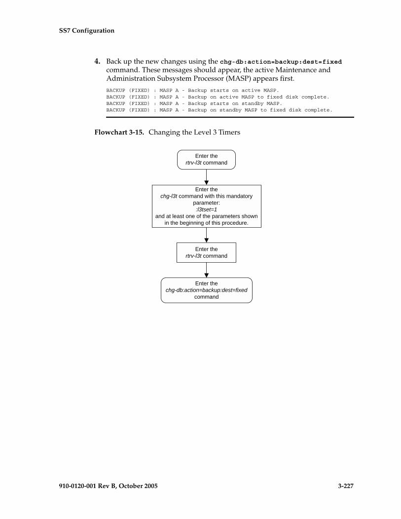
SS7 Configuration
910-0120-001 Rev B, October 2005 3-227
4. Back up the new changes using the chg-db:action=backup:dest=fixed command. These messages should appear, the active Maintenance and Administration Subsystem Processor (MASP) appears first.
BACKUP (FIXED) : MASP A - Backup starts on active MASP.BACKUP (FIXED) : MASP A - Backup on active MASP to fixed disk complete.BACKUP (FIXED) : MASP A - Backup starts on standby MASP.BACKUP (FIXED) : MASP A - Backup on standby MASP to fixed disk complete.
Flowchart 3-15. Changing the Level 3 Timers

3-228 910-0120-001 Rev B, October 2005
SS7 Configuration
Changing a Signaling Link Test Message
This procedure is used to change an SLTM (signaling link test message) using the chg-slt command.
The chg-slt command uses these parameters.
:sltset – The signaling link test message record number in the SLTM table.
:t1 – The T1 timer for repeating the SLTM after a failure
:t2 – The T2 timer for the SLTM period
:enabled – Enables the signaling link test message.
:mode – The SLTM mode to be used when sending test messages.
:pattern – The test pattern to be sent with a signaling link test message.
Procedure
1. Display the SLTM record to be changed using the rtrv-slt command. This is an example of the possible output.
rlghncxa03w 05-09-07 00:21:24 GMT EAGLE5 34.0.0SLTM PARAMETERS SLTSET T1 T2 MODE ENABLED PATTERN 1 9.0 60.0 SPECIAL ON AA2233445566778899AABBCCDDEEFF2 12.0 30.0 SPECIAL OFF F01234BCDE 3 4.0 50.0 REGULAR ON CC2233445566778899AABBCCDDEEFF4 6.0 90.0 SPECIAL OFF BB23446789BCABEFG5 6.0 90.0 SPECIAL OFF BB23446789BCABEFG6 6.0 90.0 SPECIAL OFF BB23446789BCABEFG7 6.0 90.0 SPECIAL OFF BB23446789BCABEFG8 6.0 90.0 SPECIAL OFF BB23446789BCABEFG9 6.0 90.0 REGULAR OFF BB23446789BCABEFG10 6.0 90.0 REGULAR OFF BB23446789BCABEFG11 6.0 90.0 REGULAR OFF BB23446789BCABEFG12 4.0 50.0 SPECIAL ON FFEEDDCCBBAA99887766554433221113 4.0 50.0 SPECIAL ON EE2233445514 6.0 90.0 SPECIAL ON AABBCCDD15 6.0 90.0 REGULAR ON AABBCCDD16 6.0 90.0 REGULAR ON AABBCCDD17 6.0 90.0 REGULAR ON AABBCCDD18 6.0 90.0 SPECIAL ON AABBCCDD19 6.0 90.0 SPECIAL ON AABBCCDD20 6.0 90.0 SPECIAL ON AABBCCDD
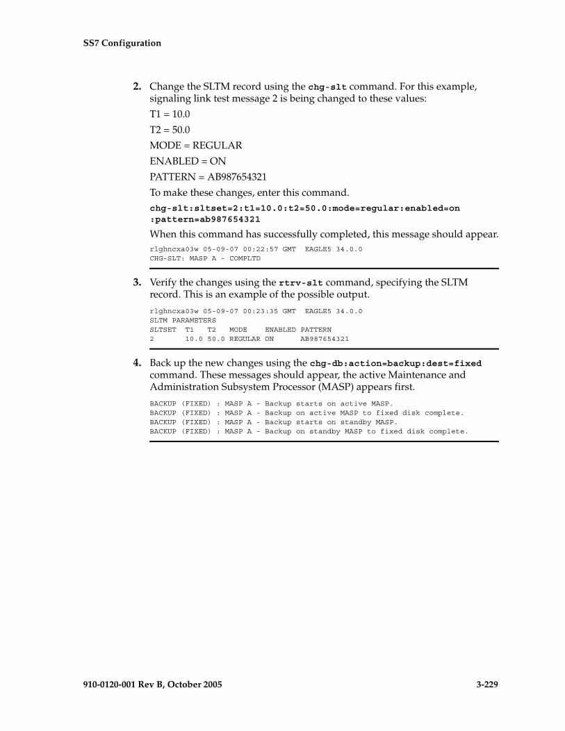
SS7 Configuration
910-0120-001 Rev B, October 2005 3-229
2. Change the SLTM record using the chg-slt command. For this example, signaling link test message 2 is being changed to these values:
T1 = 10.0
T2 = 50.0
MODE = REGULAR
ENABLED = ON
PATTERN = AB987654321
To make these changes, enter this command.chg-slt:sltset=2:t1=10.0:t2=50.0:mode=regular:enabled=on:pattern=ab987654321
When this command has successfully completed, this message should appear.rlghncxa03w 05-09-07 00:22:57 GMT EAGLE5 34.0.0CHG-SLT: MASP A - COMPLTD
3. Verify the changes using the rtrv-slt command, specifying the SLTM record. This is an example of the possible output.
rlghncxa03w 05-09-07 00:23:35 GMT EAGLE5 34.0.0SLTM PARAMETERSSLTSET T1 T2 MODE ENABLED PATTERN2 10.0 50.0 REGULAR ON AB987654321
4. Back up the new changes using the chg-db:action=backup:dest=fixed command. These messages should appear, the active Maintenance and Administration Subsystem Processor (MASP) appears first.
BACKUP (FIXED) : MASP A - Backup starts on active MASP.BACKUP (FIXED) : MASP A - Backup on active MASP to fixed disk complete.BACKUP (FIXED) : MASP A - Backup starts on standby MASP.BACKUP (FIXED) : MASP A - Backup on standby MASP to fixed disk complete.

3-230 910-0120-001 Rev B, October 2005
SS7 Configuration
Flowchart 3-16. Changing a Signaling Link Test Message

SS7 Configuration
910-0120-001 Rev B, October 2005 3-231
Configuring Circular Route Detection
NOTE: Circular route detection is not supported in ITU networks.
This procedure is used to configure the EAGLE 5 SAS to detect circular routing with the chg-stpopts command. The chg-stpopts command uses these parameters to detect circular routing in the EAGLE 5 SAS.
:mtplti – is the circular routing detection test feature is on or off?
:mtpltctdpcq – the number of DPCs that the circular route test message is sent to.
:mtpltst – the duration of the circular route test detection procedures, in milliseconds (the MTPLTST timer).
These parameters are optional. For any parameters not specified with the chg-stpopts command, the values for these parameters are not changed.
When the chg-stpopts command is first introduced to the EAGLE 5 SAS, the default values for these parameters are: mtplti=yes, mtpltctdpcq=3, and mtpltst=10000.
For this example, the circular route detection procedures remain enabled, the number of most frequently occurring DPCs is changed from 3 to 6, and the duration of the circular route detection procedures is changed from 10000 milliseconds to 18000 milliseconds.
The EAGLE 5 SAS automatically tests for circular routing when congestion occurs on an ANSI signaling link. The circular route detection test cannot be performed for ITU or X25 signaling links. If the routing data is configured incorrectly, or is corrupted, MSUs could be routed in an endless circular route. The incorrect routing data could be on the EAGLE 5 SAS or at a remote node. With the addition of cluster routing and E links, the danger of circular routing is greater.
The EAGLE 5 SAS starts the test when a signaling link reaches onset congestion threshold 1. The EAGLE 5 SAS only runs the test for one signaling link per linkset. If a second signaling link in the same linkset goes into congestion, the EAGLE 5 SAS does not start a new test. Each time the signaling link’s congestion level increases, the test is restarted. The LIM that contains the congested signaling link determines which DPCs have the most MSUs transmitted on the signaling link. The LIM then transmits a circular routing test message to the DPCs that have sent the most MSUs. The number of DPCs that the circular route test message is sent to is from 3 to 10. A circular routing test message is a routeset congestion test message with priority of 3.

3-232 910-0120-001 Rev B, October 2005
SS7 Configuration
If any LIM receives one of the test messages before the MTPLTST timer expires, the EAGLE 5 SAS performs these actions.
• Marks the destination as prohibited due to circular routing.
• Broadcasts TFPs for the destination.
• Reports that circular routing was detected for the destination.
• Raises a critical alarm.
The destination remains prohibited until it is manually allowed using the rst-dstn (reset destination) command.
If the destination is a cluster point code entry in the routing table, then an exception list (x-list) entry is created for the destination. If the cluster has the exception list exclusion indicator set to yes (meaning do not create x-lists for that cluster), then an x-list is not created, an UAM is generated, and a critical alarm is raised for the cluster. The critical alarm can be cleared by entering the rst-dstn command for the cluster.
If an x-list entry needs to be created, but the provisioned number of x-lists are already used, extra buffer space, equal to 100 entries in the routing table, is used to create the x-list. If this extra buffer space is also full, no x-list is created, a UAM is generated, and a critical alarm is raised for the cluster.
When a point code is prohibited due to circular routing, the EAGLE 5 SAS ignores TFx/TCx management messages for that point code. The EAGLE 5 SAS does not send routeset test messages for the point code. The EAGLE 5 SAS discards any MSUs received for the point code and sends response method TFPs or TCPs.
When EAGLE 5 SAS detects circular routing for a destination, it sets the circular routing flag for the destination in the routing table. The rst-dstn command clears this flag. Once the circular routing flag is cleared, the status of the destination depends on what type of entry is used.
• If the destination is a member of a cluster for which EAGLE 5 SAS performs full point code routing only, all routes to the destination are marked as allowed and the destination’s status is allowed. The EAGLE 5 SAS broadcasts TFAs for the destination.
• If the destination has a full point code entry in the routing table, and there is also an entry for the point code’s cluster, then each route used by the point code that is also used by the cluster entry assumes the status of the route for the cluster entry. Each route used by the point code that is not used by the cluster assumes the status of the cluster’s route set. The EAGLE 5 SAS then determines the point codes route set status and broadcasts TFA/TFR if the point code becomes allowed or restricted.
If the rst-dstn command is entered for an x-list entry with the circular routing flag set, the x-list entry is deleted. The point code’s status becomes the same as the cluster entry’s status.

SS7 Configuration
910-0120-001 Rev B, October 2005 3-233
Procedure
1. Display the existing values for the circular route test parameters by entering the rtrv-stpopts command. The value for the circular route test parameters is shown in the MTPLTI, MTPLTCTDPCQ, MTPLTST fields. This is an example of the possible output.
rlghncxa03w 05-09-17 16:02:05 GMT EAGLE5 34.0.0STP OPTIONS-----------------------MTPLTI yesMTPLTCTDPCQ 3MTPLTST 10000
NOTE: The rtrv-stpopts command output contains other fields that are not used by this procedure. If you wish to see all the fields displayed by the rtrv-stpopts command, see the rtrv-stpopts command description in the Commands Manual.
2. Change the circular routing detection parameters. For this example, enter this command.
chg-stpopts:mtpltctdpcq=6:mtpltst=18000
When this command has successfully completed, this message should appear.
rlghncxa03w 05-09-07 00:22:57 GMT EAGLE5 34.0.0CHG-STPOPTS: MASP A - COMPLTD
3. Verify the changes using the rtrv-stpopts command. This is an example of the possible output.
rlghncxa03w 05-09-17 16:02:05 GMT EAGLE5 34.0.0STP OPTIONS-----------------------MTPLTI yesMTPLTCTDPCQ 6MTPLTST 18000
NOTE: The rtrv-stpopts command output contains other fields that are not used by this procedure. If you wish to see all the fields displayed by the rtrv-stpopts command, see the rtrv-stpopts command description in the Commands Manual.

3-234 910-0120-001 Rev B, October 2005
SS7 Configuration
4. Back up the new changes using the chg-db:action=backup:dest=fixed command. These messages should appear, the active Maintenance and Administration Subsystem Processor (MASP) appears first.
BACKUP (FIXED) : MASP A - Backup starts on active MASP.BACKUP (FIXED) : MASP A - Backup on active MASP to fixed disk complete.BACKUP (FIXED) : MASP A - Backup starts on standby MASP.BACKUP (FIXED) : MASP A - Backup on standby MASP to fixed disk complete.
Flowchart 3-17. Configuring the System to Detect Circular Routing
SS7 Configuration
910-0120-001 Rev B, October 2005 3-235
Configuring the TFA/TFR Pacing Rate
NOTE: The pacing rate feature is not supported in ITU networks.
This procedure is used to configure the rate that the EAGLE 5 SAS sends the TFR and TFA messages, or the pacing rate. The pacing rate is configured with the tfatfrpr parameter of the chg-stpopts command. The value of the tfatfrpr parameter is from 0 to 1 second and can be set in 0.1 second intervals. When the chg-stpopts command is first introduced to the EAGLE 5 SAS, the default value for the tfatfrpr parameter is 1 second. A value of 0 for the tfatfrpr parameter indicates that the pacing should stop. The pacing of TFR/TCR is stopped and all remaining TFR/TCR are broadcast at once if the current alternate route used to route traffic to the affected point code is in danger of congestion. The value of the tfatfrpr parameter in the chg-stpopts command is entered and displayed in the rtrv-stpopts command output in milliseconds.
These parameters of the chg-stpopts command are optional. For any parameters not specified with the chg-stpopts command, the values for these parameters are not changed.
For this example, the TFA/TFR pacing rate is changed from 1 second to 0.5 seconds (1000 milliseconds to 500 milliseconds).
When the status of the route is changed to allowed (when the route was restricted) or restricted (when the route was prohibited), a burst of rerouted traffic can occur on that route, thus congesting the route. To help keep this from happening, the EAGLE 5 SAS can control the rate that it broadcasts TFR and TFA messages to adjacent signaling points. This can regulate the amount of traffic the adjacent signaling points can send to the EAGLE 5 SAS when the route becomes allowed or restricted.
The TFA/TCA and TFR/TCR messages for each affected point code are sent in groups of 20%. For each time period defined by the pacing rate, a group of 20% of the messages that are to be sent to the adjacent signaling points are broadcast to those signaling points.
This feature applies only to ANSI signaling links. The pacing is not done towards ITU networks.
If the destination becomes inaccessible or accessible before all of the TFR/TCR messages are broadcasted, then the remaining TFR/TCR messages are not sent.
TFA/TFC messages for multiple affected destinations are sent in parallel.
The broadcast of TFA/TFR messages sent about X.25 pseudo point codes is controlled by this feature.
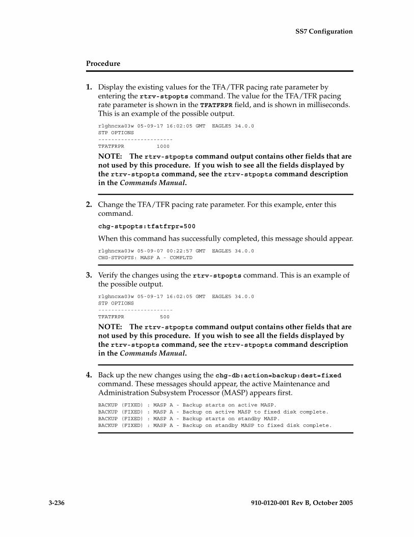
3-236 910-0120-001 Rev B, October 2005
SS7 Configuration
Procedure
1. Display the existing values for the TFA/TFR pacing rate parameter by entering the rtrv-stpopts command. The value for the TFA/TFR pacing rate parameter is shown in the TFATFRPR field, and is shown in milliseconds. This is an example of the possible output.
rlghncxa03w 05-09-17 16:02:05 GMT EAGLE5 34.0.0STP OPTIONS-----------------------TFATFRPR 1000
NOTE: The rtrv-stpopts command output contains other fields that are not used by this procedure. If you wish to see all the fields displayed by the rtrv-stpopts command, see the rtrv-stpopts command description in the Commands Manual.
2. Change the TFA/TFR pacing rate parameter. For this example, enter this command.
chg-stpopts:tfatfrpr=500
When this command has successfully completed, this message should appear.
rlghncxa03w 05-09-07 00:22:57 GMT EAGLE5 34.0.0CHG-STPOPTS: MASP A - COMPLTD
3. Verify the changes using the rtrv-stpopts command. This is an example of the possible output.
rlghncxa03w 05-09-17 16:02:05 GMT EAGLE5 34.0.0STP OPTIONS-----------------------TFATFRPR 500
NOTE: The rtrv-stpopts command output contains other fields that are not used by this procedure. If you wish to see all the fields displayed by the rtrv-stpopts command, see the rtrv-stpopts command description in the Commands Manual.
4. Back up the new changes using the chg-db:action=backup:dest=fixed command. These messages should appear, the active Maintenance and Administration Subsystem Processor (MASP) appears first.
BACKUP (FIXED) : MASP A - Backup starts on active MASP.BACKUP (FIXED) : MASP A - Backup on active MASP to fixed disk complete.BACKUP (FIXED) : MASP A - Backup starts on standby MASP.BACKUP (FIXED) : MASP A - Backup on standby MASP to fixed disk complete.
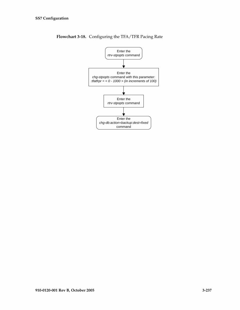
SS7 Configuration
910-0120-001 Rev B, October 2005 3-237
Flowchart 3-18. Configuring the TFA/TFR Pacing Rate

3-238 910-0120-001 Rev B, October 2005
SS7 Configuration
Configuring the Frequency of RST Messages on Low Priority Routes
This procedure is used to configure the frequency that signaling-route-set-test messages are sent for routes of lower priority than the current route. The frequency is configured with the mtplprst and mtpt10alt parameters of the chg-stpopts command.
:mtplprst – turns on or off the routeset test message for lower priority routes capability. The values for this parameter is yes or no. The default value for this parameter is yes.:mtpt10alt – the timer to control the frequency that the routeset test messages are sent. The values for this parameter are from 20000 to 10,000,000 milliseconds (20 - 10,000 seconds). The default value for this parameter is equal to the value of the level 3 T10 timer. The value of the level 3 T10 timer is shown in the T10 field of the rtrv-l3t command output.
The value of the mtpt10alt parameter must be equal to or greater than the value of the level 3 T10 timer.When the mtplprst=no parameter is specified with the chg-stpopts command, the EAGLE 5 SAS does not send routeset test messages for the lower priority routes. When the mtplprst=yes parameter is specified, the EAGLE 5 SAS sends routeset test messages at intervals specified by the value of the mtpt10alt parameter.
These parameters of the chg-stpopts command are optional. For any parameters not specified with the chg-stpopts command, the values for these parameters are not changed.For this example, the sending the signaling-route-set-test messages for the low priority routes is turned on, and the frequency of sending these messages is changed from 20 seconds to 120 seconds (20,000 milliseconds to 120,000 milliseconds).
Procedure
1. Display the existing values for the mtplprst and mtpt10alt parameters by entering the rtrv-stpopts command. The value for the mtplprst and mtpt10alt parameters is shown in the MTPLPRST and MTPT10ALT fields, and the value of the mtpt10alt parameter is shown in milliseconds.
This is an example of the possible output.rlghncxa03w 05-09-17 16:02:05 GMT EAGLE5 34.0.0STP OPTIONS-----------------------MTPLPRST noMTPT10ALT 30000
NOTE: The rtrv-stpopts command output contains other fields that are not used by this procedure. If you wish to see all the fields displayed by the rtrv-stpopts command, see the rtrv-stpopts command description in the Commands Manual.

SS7 Configuration
910-0120-001 Rev B, October 2005 3-239
2. Display the values for the level 3 timer set using the rtrv-l3t command. The values of the level 3 timers are shown in seconds. This is an example of the possible output.
rlghncxa03w 05-09-17 16:03:12 GMT EAGLE5 34.0.0LEVEL 3 TIMERS (IN SECONDS)
L3TSET T1 T2 T3 T4 T5 T6 T7 1 2.0 3.0 2.0 2.0 2.0 2.0 3.0
T8 T9 T10 T11 T12 T13 T14 2.0 -- 90.0 90.0 2.0 2.0 4.0
T15 T16 T17 T18 IT18 T19 IT19 4.0 3.0 2.0 20.0 19.0 600.0 67.0
T20/IT22 IT20 T21/IT23 IT21 T22 T23 T24 120.0 59.0 120.0 63.0 10.0 10.0 10.0
T25 T26 T27 T28 T29 T30 T31 30.0 12.0 -- 3.0 60.0 30.0 60.0
T32 60.0
3. Change the mtplprst and mtpt10alt parameters. For this example, enter this command.
chg-stpopts:mtplprst=yes:mtpt10alt=120000
When this command has successfully completed, this message should appear.rlghncxa03w 05-09-07 00:22:57 GMT EAGLE5 34.0.0CHG-STPOPTS: MASP A - COMPLTD
4. Verify the changes using the rtrv-stpopts command. This is an example of the possible output.
rlghncxa03w 05-09-17 16:02:05 GMT EAGLE5 34.0.0STP OPTIONS-----------------------MTPLPRST yesMTPT10ALT 120000
NOTE: The rtrv-stpopts command output contains other fields that are not used by this procedure. If you wish to see all the fields displayed by the rtrv-stpopts command, see the rtrv-stpopts command description in the Commands Manual.
5. Back up the new changes using the chg-db:action=backup:dest=fixed command. These messages should appear, the active Maintenance and Administration Subsystem Processor (MASP) appears first.
BACKUP (FIXED) : MASP A - Backup starts on active MASP.BACKUP (FIXED) : MASP A - Backup on active MASP to fixed disk complete.BACKUP (FIXED) : MASP A - Backup starts on standby MASP.BACKUP (FIXED) : MASP A - Backup on standby MASP to fixed disk complete.

3-240 910-0120-001 Rev B, October 2005
SS7 Configuration
Flowchart 3-19. Configuring the Frequency of RST Messages on Low Priority Routes
SS7 Configuration
910-0120-001 Rev B, October 2005 3-241
Adding Remote Loopback Points
This procedure is used to add remote loopback points to be used by the link fault sectionalization feature to the database, using the ent-lbp command. The ent-lbp command uses these parameters.
:loc – The card location of the signaling link to be tested.
:link – The signaling link on the card specified in the loc parameter to be tested.
:lbp – Identifies the far-end loopback point that lies along a SS7 signaling link path between the EAGLE 5 SAS up to and including the target device.
:clli – The CLLI code or other mnemonic identifier used to describe the specified loopback point.
:rle – The remote link element to be looped back for testing.
:rep – The number of link elements of the same type, not including the target device, that lies between the EAGLE 5 SAS and the link element to be tested.
:lfst – The type of link fault sectionalization loopback test to be performed.
To add remote loopback points to the database, the link fault sectionalization feature must be turned on.
The DS0 and network element interface (NEI) link elements do not support non-latching loopbacks
If the remote link element to be tested is a network element interface (NEI), the value of the rep parameter must be zero.
The rep parameter can only be specified for a link fault sectionalization latching loopback test
The signaling link being tested can be assigned to one of these card types as defined by the type parameter of the ent-card command:
• limds0 (multi-port LIM - P/N 870-2061-XX or LIM-AINF card - P/N 870-1488-XX)
• limt1 (E1/T1 MIM - P/N 870-2198-XX or HC MIM - P/N 870-2671-01)
• limch (E1/T1 MIM - configured as a T1 channel card - P/N 870-2198-XX)
Any signaling link can be selected for testing, as long as the signaling link being tested is equipped. The LIMs must be assigned to either the ss7ansi or ccs7itu application. Use the rtrv-card command to verify the card type and the application.
The specified loopback point cannot already be in the database.
The loopback point ID value cannot exceed a previously defined network element interface loopback point value.

3-242 910-0120-001 Rev B, October 2005
SS7 Configuration
Only one network element interface loopback point can be defined for each SS7 signaling link.
A network element interface (NEI) loopback point must be defined as the terminating SS7 signaling link component.
The value specified for the rep parameter must be greater than the value of the rep parameter assigned to the previous loopback point and less than any rep parameter values for any subsequent loopback points, if any are defined. For example, the signaling link on card 1215, link B, has 5 loopback points defined (see the rtrv-lbp command output in step 2). The value of the rep parameter used for loopback point 5 must be greater that the rep parameter value used for loopback point 3, and less than the rep parameter value used for loopback point 7.
The link fault sectionalization feature must be turned on. Verify this by entering the rtrv-feat command. If the link fault sectionalization feature is off, shown by the entry LFS = off in the output of the rtrv-feat command, it can be turned on by entering the chg-feat:lfs=on command.
NOTE: Once the link fault sectionalization feature is turned on with the chg-feat command, it cannot be turned off.
The link fault sectionalization feature must be purchased before you turn the feature on with the chg-feat command. If you are not sure if you have purchased the link fault sectionalization feature, contact your Tekelec Sales Representative or Account Representative.
Refer to Appendix A of the Commands Manual for a summary of loopback testing commands and functions.
The examples used in this procedure are based on the example network shown in Figure 3-3 and Table 3-14.
Table 3-14. Loopback Point Configuration Table
SLKLBP RLE REP LFST
LOC LINK
1204 B
3 DS0 0 LLT
6 DS0 4 LLT
9 NEI 0 LLT

SS7 Configuration
910-0120-001 Rev B, October 2005 3-243
Canceling the RTRV-SLK Command
Because the rtrv-slk command used in this procedure can output information for a long period of time, the rtrv-slk command can be canceled and the output to the terminal stopped. There are three ways that the rtrv-slk command can be canceled.
• Press the F9 function key on the keyboard at the terminal where the rtrv-slk command was entered.
• Enter the canc-cmd without the trm parameter at the terminal where the rtrv-slk command was entered.
• Enter the canc-cmd:trm=<xx>, where <xx> is the terminal where the rtrv-slk command was entered, from another terminal other that the terminal where the rtrv-slk command was entered. To enter the canc-cmd:trm=<xx> command, the terminal must allow Security Administration commands to be entered from it and the user must be allowed to enter Security Administration commands. The terminal’s permissions can be verified with the rtrv-secu-trm command. The user’s permissions can be verified with the rtrv-user or rtrv-secu-user commands.
For more information about the canc-cmd command, go to the Commands Manual.
Procedure
1. Display the signaling links in the database by entering the rtrv-slk command. This is an example of the possible output.
rlghncxa03w 05-09-19 21:16:37 GMT EAGLE5 34.0.0 L2T L1 PCR PCRLOC LINK LSN SLC TYPE SET BPS MODE TSET ECM N1 N21201 A ls01 0 LIMDS0 1 56000 --- --- BASIC --- -----1201 B lsa1 0 LIMDS0 1 56000 --- --- BASIC --- -----1202 B ls02 0 LIMV35 2 64000 DTE --- BASIC --- -----1203 A ls03 0 LIMDS0 3 56000 --- --- BASIC --- -----1203 B lsa2 0 LIMDS0 1 56000 --- --- BASIC --- -----1204 B ls01 1 LIMDS0 1 56000 --- --- BASIC --- -----1205 A lsa3 0 LIMV35 4 64000 DCE ON BASIC --- -----1206 A ls02 1 LIMV35 2 64000 DTE --- BASIC --- -----1207 A lsn1207a 0 LIMDS0 1 56000 --- --- BASIC --- -----1207 B lsn1207b 0 LIMDS0 1 56000 --- --- BASIC --- -----1208 B ls03 1 LIMDS0 3 56000 --- --- BASIC --- -----1212 A ls04 0 LIMV35 4 64000 DTE --- BASIC --- -----1213 B ls05 0 LIMDS0 5 56000 --- --- BASIC --- -----1214 A lsn1214a 0 LIMV35 2 64000 DTE --- PCR 76 38001214 B lsa3 1 LIMV35 4 64000 DCE ON BASIC --- -----1215 A ls05 1 LIMDS0 5 56000 --- --- BASIC --- -----1301 B ls06 0 LIMV35 6 56000 DTE --- BASIC --- -----1304 B ls06 1 LIMV35 6 56000 DTE --- BASIC --- -----1308 A ls06 2 LIMV35 6 56000 DTE --- BASIC --- -----1311 A ls01 2 LIMDS0 1 56000 --- --- BASIC --- -----1311 A1 ls05 2 LIMDS0 5 56000 --- --- BASIC --- -----1311 B ls03 2 LIMDS0 3 56000 --- --- BASIC --- -----1311 B1 ls07 1 LIMDS0 7 56000 --- --- BASIC --- -----1313 A ls07 0 LIMDS0 7 56000 --- --- BASIC --- -----
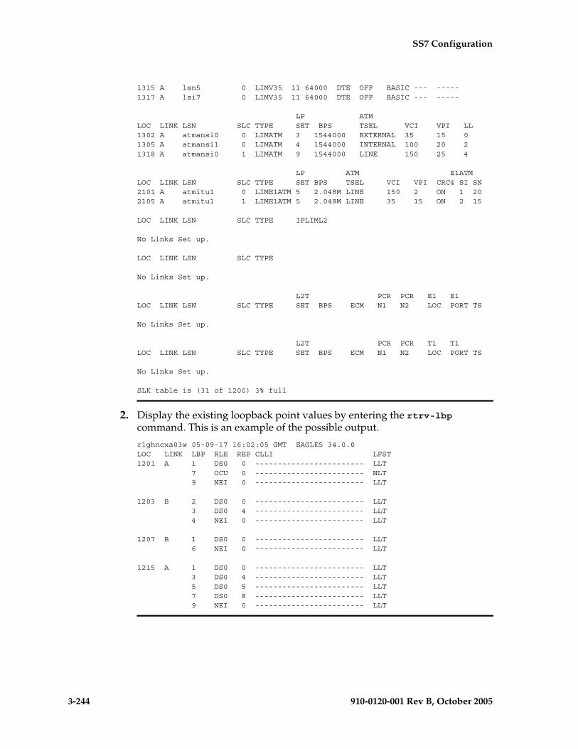
3-244 910-0120-001 Rev B, October 2005
SS7 Configuration
1315 A lsn5 0 LIMV35 11 64000 DTE OFF BASIC --- -----1317 A lsi7 0 LIMV35 11 64000 DTE OFF BASIC --- -----
LP ATMLOC LINK LSN SLC TYPE SET BPS TSEL VCI VPI LL1302 A atmansi0 0 LIMATM 3 1544000 EXTERNAL 35 15 01305 A atmansi1 0 LIMATM 4 1544000 INTERNAL 100 20 21318 A atmansi0 1 LIMATM 9 1544000 LINE 150 25 4
LP ATM E1ATMLOC LINK LSN SLC TYPE SET BPS TSEL VCI VPI CRC4 SI SN2101 A atmitu1 0 LIME1ATM 5 2.048M LINE 150 2 ON 1 202105 A atmitu1 1 LIME1ATM 5 2.048M LINE 35 15 ON 2 15
LOC LINK LSN SLC TYPE IPLIML2
No Links Set up.
LOC LINK LSN SLC TYPE
No Links Set up.
L2T PCR PCR E1 E1LOC LINK LSN SLC TYPE SET BPS ECM N1 N2 LOC PORT TS
No Links Set up.
L2T PCR PCR T1 T1LOC LINK LSN SLC TYPE SET BPS ECM N1 N2 LOC PORT TS
No Links Set up.
SLK table is (31 of 1200) 3% full
2. Display the existing loopback point values by entering the rtrv-lbp command. This is an example of the possible output.
rlghncxa03w 05-09-17 16:02:05 GMT EAGLE5 34.0.0LOC LINK LBP RLE REP CLLI LFST1201 A 1 DS0 0 ------------------------ LLT 7 OCU 0 ------------------------ NLT 9 NEI 0 ------------------------ LLT 1203 B 2 DS0 0 ------------------------ LLT 3 DS0 4 ------------------------ LLT 4 NEI 0 ------------------------ LLT
1207 B 1 DS0 0 ------------------------ LLT 6 NEI 0 ------------------------ LLT
1215 A 1 DS0 0 ------------------------ LLT 3 DS0 4 ------------------------ LLT 5 DS0 5 ------------------------ LLT 7 DS0 8 ------------------------ LLT 9 NEI 0 ------------------------ LLT

SS7 Configuration
910-0120-001 Rev B, October 2005 3-245
3. Add the loopback point to the database, using the ent-lbp command. For this example, enter these commands.
ent-lbp:loc=1204:link=b:lbp=3:rle=ds0:rep=0:lfst=llt
ent-lbp:loc=1204:link=b:lbp=6:rle=ds0:rep=4:lfst=llt
ent-lbp:loc=1204:link=b:lbp=9:rle=nei:rep=0:lfst=llt
When each of these commands have completed, this message should appear.
rlghncxa03w 05-09-07 00:22:57 GMT EAGLE5 34.0.0ENT-LBP: MASP A - COMPLTD
4. Verify the changes using the rtrv-lbp command. This is an example of the possible output.
rlghncxa03w 05-09-17 16:02:05 GMT EAGLE5 34.0.0LOC LINK LBP RLE REP CLLI LFST1201 A 1 DS0 0 ------------------------ LLT 7 OCU 0 ------------------------ NLT 9 NEI 0 ------------------------ LLT 1203 B 2 DS0 0 ------------------------ LLT 3 DS0 4 ------------------------ LLT 4 NEI 0 ------------------------ LLT
1204 B 3 DS0 0 ------------------------ LLT 6 DS0 4 ------------------------ LLT 9 NEI 0 ------------------------ LLT
1207 B 1 DS0 0 ------------------------ LLT 6 NEI 0 ------------------------ LLT
1215 A 1 DS0 0 ------------------------ LLT 3 DS0 4 ------------------------ LLT 5 DS0 5 ------------------------ LLT 7 DS0 8 ------------------------ LLT 9 NEI 0 ------------------------ LLT
5. Back up the new changes using the chg-db:action=backup:dest=fixed command. These messages should appear, the active Maintenance and Administration Subsystem Processor (MASP) appears first.
BACKUP (FIXED) : MASP A - Backup starts on active MASP.BACKUP (FIXED) : MASP A - Backup on active MASP to fixed disk complete.BACKUP (FIXED) : MASP A - Backup starts on standby MASP.BACKUP (FIXED) : MASP A - Backup on standby MASP to fixed disk complete.

3-246 910-0120-001 Rev B, October 2005
SS7 Configuration
Flowchart 3-20. Adding Remote Loopback Points
NOTE: Before executing this procedure, make sure you have purchased the link fault sectionalization feature. If you are not sure if you have purchased the link fault sectionalization feature, contact your Tekelec Sales Representative or Account Representative.
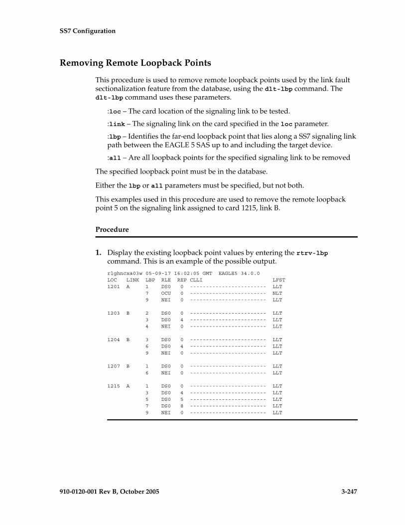
SS7 Configuration
910-0120-001 Rev B, October 2005 3-247
Removing Remote Loopback Points
This procedure is used to remove remote loopback points used by the link fault sectionalization feature from the database, using the dlt-lbp command. The dlt-lbp command uses these parameters.
:loc – The card location of the signaling link to be tested.
:link – The signaling link on the card specified in the loc parameter.
:lbp – Identifies the far-end loopback point that lies along a SS7 signaling link path between the EAGLE 5 SAS up to and including the target device.
:all – Are all loopback points for the specified signaling link to be removed
The specified loopback point must be in the database.
Either the lbp or all parameters must be specified, but not both.
This examples used in this procedure are used to remove the remote loopback point 5 on the signaling link assigned to card 1215, link B.
Procedure
1. Display the existing loopback point values by entering the rtrv-lbp command. This is an example of the possible output.
rlghncxa03w 05-09-17 16:02:05 GMT EAGLE5 34.0.0LOC LINK LBP RLE REP CLLI LFST1201 A 1 DS0 0 ------------------------ LLT 7 OCU 0 ------------------------ NLT 9 NEI 0 ------------------------ LLT 1203 B 2 DS0 0 ------------------------ LLT 3 DS0 4 ------------------------ LLT 4 NEI 0 ------------------------ LLT
1204 B 3 DS0 0 ------------------------ LLT 6 DS0 4 ------------------------ LLT 9 NEI 0 ------------------------ LLT
1207 B 1 DS0 0 ------------------------ LLT 6 NEI 0 ------------------------ LLT
1215 A 1 DS0 0 ------------------------ LLT 3 DS0 4 ------------------------ LLT 5 DS0 5 ------------------------ LLT 7 DS0 8 ------------------------ LLT 9 NEI 0 ------------------------ LLT

3-248 910-0120-001 Rev B, October 2005
SS7 Configuration
2. Remove the loopback point from the database, using the dlt-lbp command. For this example, enter this command.
dlt-lbp:loc=1215:link=b:lbp=5
If all the loopback points on the signaling link are to be removed from the database, enter this command.
dlt-lbp:loc=1215:link=b:all=yes
When the command has completed, this message should appear.
rlghncxa03w 05-09-07 00:22:57 GMT EAGLE5 34.0.0DLT-LBP: MASP A - COMPLTD
3. Verify the changes using the rtrv-lbp command. This is an example of the possible output.
rlghncxa03w 05-09-17 16:02:05 GMT EAGLE5 34.0.0LOC LINK LBP RLE REP CLLI LFST1201 A 1 DS0 0 ------------------------ LLT 7 OCU 0 ------------------------ NLT 9 NEI 0 ------------------------ LLT 1203 B 2 DS0 0 ------------------------ LLT 3 DS0 4 ------------------------ LLT 4 NEI 0 ------------------------ LLT
1204 B 3 DS0 0 ------------------------ LLT 6 DS0 4 ------------------------ LLT 9 NEI 0 ------------------------ LLT
1207 B 1 DS0 0 ------------------------ LLT 6 NEI 0 ------------------------ LLT
1215 A 1 DS0 0 ------------------------ LLT 3 DS0 4 ------------------------ LLT 7 DS0 8 ------------------------ LLT 9 NEI 0 ------------------------ LLT
If the all=yes parameter was specified in step 2, this is an example of the possible output.
rlghncxa03w 05-09-17 16:02:05 GMT EAGLE5 34.0.0LOC LINK LBP RLE REP CLLI LFST1201 A 1 DS0 0 ------------------------ LLT 7 OCU 0 ------------------------ NLT 9 NEI 0 ------------------------ LLT 1203 B 2 DS0 0 ------------------------ LLT 3 DS0 4 ------------------------ LLT 4 NEI 0 ------------------------ LLT
1204 B 3 DS0 0 ------------------------ LLT 6 DS0 4 ------------------------ LLT 9 NEI 0 ------------------------ LLT
1207 B 1 DS0 0 ------------------------ LLT 6 NEI 0 ------------------------ LLT

SS7 Configuration
910-0120-001 Rev B, October 2005 3-249
4. Back up the new changes using the chg-db:action=backup:dest=fixed command. These messages should appear, the active Maintenance and Administration Subsystem Processor (MASP) appears first.
BACKUP (FIXED) : MASP A - Backup starts on active MASP.BACKUP (FIXED) : MASP A - Backup on active MASP to fixed disk complete.BACKUP (FIXED) : MASP A - Backup starts on standby MASP.BACKUP (FIXED) : MASP A - Backup on standby MASP to fixed disk complete.
Flowchart 3-21. Removing Remote Loopback Points
3-250 910-0120-001 Rev B, October 2005
SS7 Configuration
Changing Remote Loopback Points
This procedure is used to change the values of the remote loopback points to be used by the link fault sectionalization feature in the database, using the chg-lbp command. The chg-lbp command uses these parameters.
:loc – The card location of the signaling link to be tested.
:link – The signaling link on the card specified in the loc parameter.
:lbp – Identifies the far-end loopback point that lies along a SS7 signaling link path between the EAGLE 5 SAS up to and including the target device.
:clli – The CLLI code or other mnemonic identifier used to describe the specified loopback point.
:rle – The remote link element to be looped back for testing.
:rep – The number of link elements of the same type, not including the target device, that lies between the EAGLE 5 SAS and the link element to be tested.
:lfst – The type of link fault sectionalization loopback test to be performed.
The DS0 and network element interface (NEI) link elements do not support non-latching loopbacks
If the remote link element to be tested is a network element interface (NEI), the value of the rep parameter must be zero.
The rep parameter can only be specified for a link fault sectionalization latching loopback test
The specified loopback point must be in the database.
The loopback point ID value cannot exceed a previously defined network element interface loopback point value.
Only one network element interface loopback point can be defined for each SS7 signaling link.
A network element interface (NEI) loopback point must be defined as the terminating SS7 signaling link component.
The value specified for the rep parameter must be greater than the value of the rep parameter assigned to the previous loopback point and less than any rep parameter values for any subsequent loopback points, if any are defined. For example, the signaling link on card 1215, link B, has 5 loopback points defined (see the rtrv-lbp command output in step 1). The value of the rep parameter used for loopback point 5 must be greater that the rep parameter value used for loopback point 3, and less than the rep parameter value used for loopback point 7.
Refer to Appendix A of the Commands Manual for a summary of loopback testing commands and functions.

SS7 Configuration
910-0120-001 Rev B, October 2005 3-251
The examples used in this procedure are based on the example network shown in Figure 3-3 and are used to change the values of the rep and rle parameters (rep=4, rle=ds0) for loopback point 6 on the signaling link assigned to card 1204, link B, to a repetition count of 10 (rep=10) and the RLE to CSU (rle=csu).
Procedure
1. Display the existing loopback point values by entering the rtrv-lbp command. This is an example of the possible output.
rlghncxa03w 05-09-17 16:02:05 GMT EAGLE5 34.0.0LOC LINK LBP RLE REP CLLI LFST1201 A 1 DS0 0 ------------------------ LLT 7 OCU 0 ------------------------ NLT 9 NEI 0 ------------------------ LLT 1203 B 2 DS0 0 ------------------------ LLT 3 DS0 4 ------------------------ LLT 4 NEI 0 ------------------------ LLT
1204 B 3 DS0 0 ------------------------ LLT 6 DS0 4 ------------------------ LLT 9 NEI 0 ------------------------ LLT
1207 B 1 DS0 0 ------------------------ LLT 6 NEI 0 ------------------------ LLT
1215 A 1 DS0 0 ------------------------ LLT 3 DS0 4 ------------------------ LLT 5 DS0 5 ------------------------ LLT 7 DS0 8 ------------------------ LLT 9 NEI 0 ------------------------ LLT
2. Change the loopback point values in the database, using the chg-lbp command. For this example, enter this command.
chg-lbp:loc=1204:link=b:lbp=6:rle=csu:rep=10
When the command has completed, this message should appear.
rlghncxa03w 05-09-07 00:22:57 GMT EAGLE5 34.0.0CHG-LBP: MASP A - COMPLTD

3-252 910-0120-001 Rev B, October 2005
SS7 Configuration
3. Verify the changes using the rtrv-lbp command. This is an example of the possible output.
rlghncxa03w 05-09-17 16:02:05 GMT EAGLE5 34.0.0LOC LINK LBP RLE REP CLLI LFST1201 A 1 DS0 0 ------------------------ LLT 7 OCU 0 ------------------------ NLT 9 NEI 0 ------------------------ LLT 1203 B 2 DS0 0 ------------------------ LLT 3 DS0 4 ------------------------ LLT 4 NEI 0 ------------------------ LLT
1204 B 3 DS0 0 ------------------------ LLT 6 CSU 10 ------------------------ LLT 9 NEI 0 ------------------------ LLT
1207 B 1 DS0 0 ------------------------ LLT 6 NEI 0 ------------------------ LLT
1215 A 1 DS0 0 ------------------------ LLT 3 DS0 4 ------------------------ LLT 5 DS0 5 ------------------------ LLT 7 DS0 8 ------------------------ LLT 9 NEI 0 ------------------------ LLT
4. Back up the new changes using the chg-db:action=backup:dest=fixed command. These messages should appear, the active Maintenance and Administration Subsystem Processor (MASP) appears first.
BACKUP (FIXED) : MASP A - Backup starts on active MASP.BACKUP (FIXED) : MASP A - Backup on active MASP to fixed disk complete.BACKUP (FIXED) : MASP A - Backup starts on standby MASP.BACKUP (FIXED) : MASP A - Backup on standby MASP to fixed disk complete.
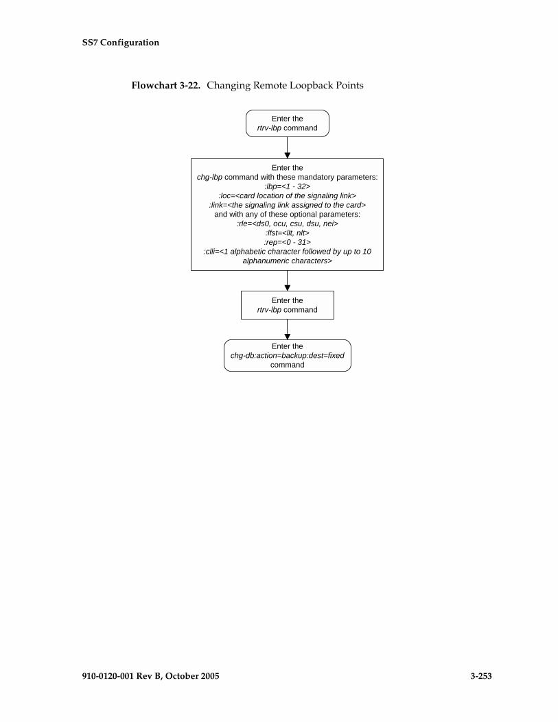
SS7 Configuration
910-0120-001 Rev B, October 2005 3-253
Flowchart 3-22. Changing Remote Loopback Points

3-254 910-0120-001 Rev B, October 2005
SS7 Configuration
Configuring the System for Random SLS Generation
The Random SLS Generation feature can alleviate problems of the EAGLE 5 SAS not load-sharing between all links within a linkset.
The ITU protocol uses a 4 bit Signaling Link Selection (SLS) field with no modification of SLS values by intermediate nodes and a one-to-one mapping of SLS values to signaling links. These rules can be overly restrictive in situations where they are not necessary.
The feature allows the user to have the EAGLE 5 SAS ignore the incoming SLS value and randomly generate a new 8-bit SLS value to select an outgoing linkset and a link. The original 4-bit SLS value is not changed and is still contained in the outgoing message. The newly generated SLS is used for link selection only. Messages destined for a particular destination are randomly distributed across all the links to that destination using an internally generated random 8-bit SLS. This means that this feature does not follow the ITU protocol requiring that all messages with the same SLS value must use the same signaling link. Also, correct sequencing of Class 1 messages is not guaranteed. Random SLS generation applies to all Class 0 and Class 1 SCCP messages. Random SLS generation is not required to support ISUP messages.
This feature is implemented with one of these values for the randsls parameter of the chg-stpopts command.
• class0 - Applies the Random SLS feature to Class 0 ITU SCCP messages and associated service For example, Random SLS Generation would apply to Class 0 UDT, XUDT, and UDTS, XUDTS messages. Class 1 messages would still use the standard ITU method for link selection.
• all - Applies the Random SLS feature to all ITU SCCP messages
• off - Turns off the Random SLS feature.
CAUTION: If the randsls parameter value of the chg-stpopts command is all, thus activating the Random SLS feature for Class 1 ITU SCCP messages, and the value of the class1seq parameter of the chg-sccpopts command is on, there is no guarantee that UDT/XUDT ITU Class 1 messages are delivered to the remote node in the order in which they were received. To ensure that Class 1 UDT/XUDT ITU messages are delivered to the remote node in the order in which they were received, the randsls parameter value should be set to either off or class0 if the value of the class1seq parameter of the chg-sccpopts command is on.
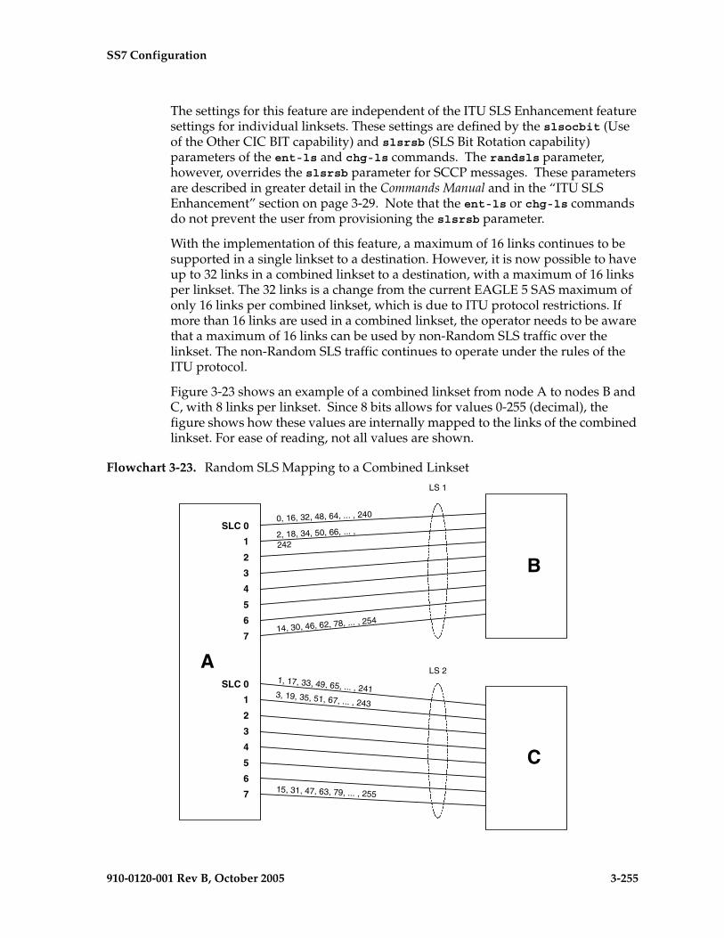
SS7 Configuration
910-0120-001 Rev B, October 2005 3-255
The settings for this feature are independent of the ITU SLS Enhancement feature settings for individual linksets. These settings are defined by the slsocbit (Use of the Other CIC BIT capability) and slsrsb (SLS Bit Rotation capability) parameters of the ent-ls and chg-ls commands. The randsls parameter, however, overrides the slsrsb parameter for SCCP messages. These parameters are described in greater detail in the Commands Manual and in the “ITU SLS Enhancement” section on page 3-29. Note that the ent-ls or chg-ls commands do not prevent the user from provisioning the slsrsb parameter.
With the implementation of this feature, a maximum of 16 links continues to be supported in a single linkset to a destination. However, it is now possible to have up to 32 links in a combined linkset to a destination, with a maximum of 16 links per linkset. The 32 links is a change from the current EAGLE 5 SAS maximum of only 16 links per combined linkset, which is due to ITU protocol restrictions. If more than 16 links are used in a combined linkset, the operator needs to be aware that a maximum of 16 links can be used by non-Random SLS traffic over the linkset. The non-Random SLS traffic continues to operate under the rules of the ITU protocol.
Figure 3-23 shows an example of a combined linkset from node A to nodes B and C, with 8 links per linkset. Since 8 bits allows for values 0-255 (decimal), the figure shows how these values are internally mapped to the links of the combined linkset. For ease of reading, not all values are shown.
Flowchart 3-23. Random SLS Mapping to a Combined Linkset
A
SLC 0
1
2
3
4
5
6
7
SLC 0
1
2
3
4
5
6
7
B
C
LS 1
LS 2
0, 16, 32, 48, 64, ... , 240
2, 18, 34, 50, 66, ... ,
242
14, 30, 46, 62, 78, ... , 254
1, 17, 33, 49, 65, ... , 2413, 19, 35, 51, 67, ... , 243
15, 31, 47, 63, 79, ... , 255

3-256 910-0120-001 Rev B, October 2005
SS7 Configuration
Figure 3-7 shows the mapping for a 4-link single linkset between nodes D and E. When an MSU is to be transmitted, a random 8 bit SLS is generated internally and a link is selected according to this predetermined mapping.
Figure 3-7. Random SLS Mapping to a Single Linkset
The 4 bit SLS in the outgoing message is equal to the SLS that the EAGLE 5 SAS received. There is no change to the SLS value in the SS7 message.
In a non-failure condition, the process for mapping the internally generated SLS values to SLC (Signaling Link Code) values for specific links is as follows:
1. A “random” 8-bit SLS value is generated. In reality, a single table of 256 unique SLS values, initially generated in random order, exists in the EAGLE 5 SAS. A counter is maintained for each linkset in the EAGLE 5 SAS that causes the linkset to cycle through the random values in the table as messages are routed out on that linkset. For a combined linkset, the counter for the first linkset in the EAGLE 5 SAS's linkset table is used.
2. For a combined linkset, the first bit is used to select the linkset and then is ignored when selecting the SLC. For a single linkset, the first bit is used when selecting the SLC. In all cases, the fifth bit is ignored when selecting the SLC. This is due to internal ANSI-based processing in the EAGLE 5 SAS.
3. The changed SLS value (with fifth and possibly also first bits ignored) is then divided by the number of links in the linkset (not a combined linkset) and the remainder gives the SLC value. For example, in Figure 3-23 on page 3-255, the SLS value 78 is mapped to SLC 7 in linkset LS1 as follows:
a. The binary equivalent for decimal number 78 is 01001110.
b. The fifth bit is ignored leaving the binary number 0101110.
c. The least significant bit is used to select linkset LS1 and is then ignored, leaving the binary number 010111.
d. The decimal equivalent of the binary number 010111 is 23. When the number 23 is divided by the number of links in the linkset, in this example, eight, a remainder of seven remains, thus SLC 7 on linkset LS1 is chosen for the outgoing message.
DSLC 0
1
2
3
E0, 4, 8, 12, 16, ... , 252
1, 5, 9, 13, 17, ... , 253
2, 6, 10, 14, 18, ... , 254
3, 7, 11, 15, 19, ... , 255

SS7 Configuration
910-0120-001 Rev B, October 2005 3-257
In the example shown in Figure 3-7 on page 3-256, the SLS value 78 is mapped to SLC 2 in LS1 (the only linkset) as follows:
a. The binary equivalent for decimal number 78 is 01001110.
b. The fifth bit is ignored leaving the binary number 0101110.
c. The decimal equivalent of the binary number 0101110 is 46. When the number 46 is divided by the number of links in the linkset, in this example, four, a remainder of two remains, thus SLC 2 on linkset LS1 is chosen for the outgoing message.
Table 3-15 on page 3-257 shows the mapping for a combined linkset with 16 links in each linkset. This table is discussed in more detail in the next section.
Link failure scenarios
In any situation where a link is failed, SLS values that were mapped to that link are remapped to other links of the linkset or combined linkset. This is done in the reverse order that the SLS values were originally mapped to links, of course skipping the failed link. Subsequent link failures will have their SLS values, along with SLS values from the prior failures, remapped in the same way. The odd/even mapping rule for combined linksets does not apply to the remapped SLS values under failure conditions. This is to continue to achieve the best possible load balance across all links. No MSUs should be discarded in any case.
For example, Table 3-15 shows how the internal 8-bit SLS values are distributed for a combined linkset with 16 links per linkset. It also shows what happens when one or two of the links fail. As this example shows, the SLS values that are identical after the fifth bit is dropped (for example, 0 and 16, 192 and 208, etc.) are remapped to the same link. This is why in this example the 8 different SLS values from the first failed link are remapped to only 4 links and not 8.
Table 3-15. Failure Scenarios for a 32-Link Combined Linkset
Linkset/SLC
Normal SLS Mapping SLS Mapping for Single Link Failure
SLS Mapping for Dual Link Failure
LS1/0 0 16 64 80 128 144 192 208 Failed Failed
LS1/1 2 18 66 82 130 146 194 210 Same as Normal SLS Mapping
Same as Normal SLS Mapping
LS1/7 14 30 78 94 142 158 206 222 Same as Normal SLS Mapping
Same as Normal SLS Mapping
LS1/8 32 48 96 112 160 176 224 240 Same as Normal SLS Mapping
Same as Normal SLS Mapping
LS1/9 34 50 98 114 162 178 226 242 Same as Normal SLS Mapping
Same as Normal SLS Mapping
LS1/12 40 56 104 120 168 184 232 248 Same as Normal SLS Mapping 40 56 … 248 225 241
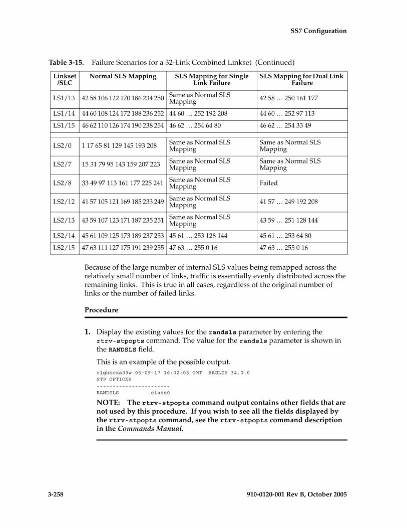
3-258 910-0120-001 Rev B, October 2005
SS7 Configuration
Because of the large number of internal SLS values being remapped across the relatively small number of links, traffic is essentially evenly distributed across the remaining links. This is true in all cases, regardless of the original number of links or the number of failed links.
Procedure
1. Display the existing values for the randsls parameter by entering the rtrv-stpopts command. The value for the randsls parameter is shown in the RANDSLS field.
This is an example of the possible output.rlghncxa03w 05-09-17 16:02:05 GMT EAGLE5 34.0.0STP OPTIONS-----------------------RANDSLS class0
NOTE: The rtrv-stpopts command output contains other fields that are not used by this procedure. If you wish to see all the fields displayed by the rtrv-stpopts command, see the rtrv-stpopts command description in the Commands Manual.
LS1/13 42 58 106 122 170 186 234 250 Same as Normal SLS Mapping 42 58 … 250 161 177
LS1/14 44 60 108 124 172 188 236 252 44 60 … 252 192 208 44 60 … 252 97 113
LS1/15 46 62 110 126 174 190 238 254 46 62 … 254 64 80 46 62 … 254 33 49
LS2/0 1 17 65 81 129 145 193 208 Same as Normal SLS Mapping
Same as Normal SLS Mapping
LS2/7 15 31 79 95 143 159 207 223 Same as Normal SLS Mapping
Same as Normal SLS Mapping
LS2/8 33 49 97 113 161 177 225 241 Same as Normal SLS Mapping Failed
LS2/12 41 57 105 121 169 185 233 249 Same as Normal SLS Mapping 41 57 … 249 192 208
LS2/13 43 59 107 123 171 187 235 251 Same as Normal SLS Mapping 43 59 … 251 128 144
LS2/14 45 61 109 125 173 189 237 253 45 61 … 253 128 144 45 61 … 253 64 80
LS2/15 47 63 111 127 175 191 239 255 47 63 … 255 0 16 47 63 … 255 0 16
Table 3-15. Failure Scenarios for a 32-Link Combined Linkset (Continued)
Linkset/SLC
Normal SLS Mapping SLS Mapping for Single Link Failure
SLS Mapping for Dual Link Failure

SS7 Configuration
910-0120-001 Rev B, October 2005 3-259
NOTE: If the randsls=all parameter will not be specified with the chg-stpopts command, skip this step and step 3, and go to step 4.
2. Verify the value of the class1seq parameter of the chg-sccpopts command by entering the rtrv-sccpopts command. This is an example of the possible output.
rlghncxa03w 05-09-17 16:02:05 GMT EAGLE5 34.0.0
SCCP OPTIONS---------------------------CLASS1SEQ on
If the value of the class1seq parameter is on, the randsls=all parameter of the chg-stpopts command should not be used. The class1seq=on parameter allows UDT/XUDT Class 1 ITU messages to be delivered to the remote node in the order that they were received. Using the randsls=all parameter with the class1seq=on parameter does not guarantee that UDT/XUDT Class1 ITU messages are delivered to the remote node in the order that they were received.
If you wish to continue delivering UDT/XUDT Class 1 ITU messages to the remote node in the order that they were received, or if the value of the class1seq parameter of the chg-sccpopts command is off, skip step 3 and go to step 4.
If you do not wish to continue delivering UDT/XUDT Class 1 ITU messages to the remote node in the order that they were received, go to step 3.
3. Change the value of the class1seq parameter of the chg-sccpopts command by entering this command.
chg-sccpopts:class1seq=off
When this command has successfully completed, this message should appear.rlghncxa03w 05-09-07 00:22:57 GMT EAGLE5 34.0.0CHG-STPOPTS: MASP A - COMPLTD
4. Change the randsls parameter value. For this example, enter this command.
chg-stpopts:randsls=all
When this command has successfully completed, this message should appear.rlghncxa03w 05-09-07 00:22:57 GMT EAGLE5 34.0.0CHG-STPOPTS: MASP A - COMPLTD

3-260 910-0120-001 Rev B, October 2005
SS7 Configuration
5. Verify the changes using the rtrv-stpopts command. This is an example of the possible output.
rlghncxa03w 05-09-17 16:02:05 GMT EAGLE5 34.0.0STP OPTIONS-----------------------RANDSLS all
NOTE: The rtrv-stpopts command output contains other fields that are not used by this procedure. If you wish to see all the fields displayed by the rtrv-stpopts command, see the rtrv-stpopts command description in the Commands Manual.
6. Back up the new changes using the chg-db:action=backup:dest=fixed command. These messages should appear, the active Maintenance and Administration Subsystem Processor (MASP) appears first.
BACKUP (FIXED) : MASP A - Backup starts on active MASP.BACKUP (FIXED) : MASP A - Backup on active MASP to fixed disk complete.BACKUP (FIXED) : MASP A - Backup starts on standby MASP.BACKUP (FIXED) : MASP A - Backup on standby MASP to fixed disk complete.

SS7 Configuration
910-0120-001 Rev B, October 2005 3-261
Flowchart 3-24. Configuring the System for Random SLS Generation (Sheet 1 of 2)
Enter the rtrv-stpoptscommand
What is the newvalue for the randsls
parameter?
OFF
CLASS0
Enter thechg-stpopts:randsls=off
command
Enter thechg-stpopts:randsls=class0
command
Enter the rtrv-stpoptscommand
Enter thechg-db:action=backup:dest=fixed
command
ToSheet 2
ALL
FromSheet 2
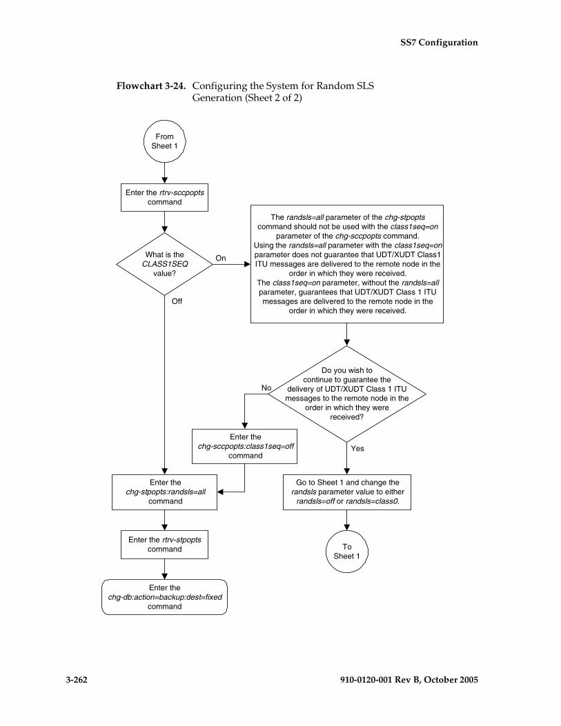
3-262 910-0120-001 Rev B, October 2005
SS7 Configuration
Flowchart 3-24. Configuring the System for Random SLS Generation (Sheet 2 of 2)
Enter thechg-stpopts:randsls=all
command
Enter the rtrv-stpoptscommand
Enter thechg-db:action=backup:dest=fixed
command
FromSheet 1
The randsls=all parameter of the chg-stpoptscommand should not be used with the class1seq=on
parameter of the chg-sccpopts command.Using the randsls=all parameter with the class1seq=onparameter does not guarantee that UDT/XUDT Class1ITU messages are delivered to the remote node in the
order in which they were received.The class1seq=on parameter, without the randsls=allparameter, guarantees that UDT/XUDT Class 1 ITUmessages are delivered to the remote node in the
order in which they were received.
Enter the rtrv-sccpoptscommand
What is theCLASS1SEQ
value?
On
Off
Do you wish tocontinue to guarantee the
delivery of UDT/XUDT Class 1 ITUmessages to the remote node in the
order in which they werereceived?
Yes
No
Go to Sheet 1 and change therandsls parameter value to either
randsls=off or randsls=class0.
Enter thechg-sccpopts:class1seq=off
command
ToSheet 1
SS7 Configuration
910-0120-001 Rev B, October 2005 3-263
Configuring the Options for the TDM Global Timing Interface
This procedure is used to configure the options for the TDM Global Timing Interface using the hsclksrc and hsclkll parameters of the chg-stpopts command and the following parameters.
:hsclksrc – the source of the high-speed master clock.
• rs422 – T1 (1544 KHz) or E1 (2048 KHz) RS-422 clock interface
• t1framed – T1 framed clocking as defined in ANSI T1.101, Synchronization Interface Standard, 1999.
• t1unframed – T1 unframed clocking as defined in ANSI T1.102, Digital Hierarchy Electrical Signals, 1987.
• e1framed – E1 framed clocking as defined in section 9 of ITU-T Recommendation G.703, Physical/Electrical Characteristics of Hierarchical Digital Interfaces, October 1998.
• e1unframed – E1 unframed clocking as defined in section 13 of ITU-T Recommendation G.703, Physical/Electrical Characteristics of Hierarchical Digital Interfaces, October 1998.
:hsclkll – sets the gain of the LIU (line interface unit) of the TDM when the hsclksrc parameter value is either t1unframed, t1unframed, e1framed, or e1unframed.
• longhaul – high gain for the LIU
• shorthaul – low gain for the LIU
CAUTION: Changing these options changes the external master clock source for all E1, T1, ANSI ATM, or E1 ATM high-speed signaling links using external timing.
:force - allows the hsclksrc parameter to be changed if the status of the high-speed clocks is valid. The force parameter must be specified when the EAGLE 5 SAS contains valid high-speed clocks. The force parameter can be specified only if the hsclksrc parameter is specified. The force parameter has only one value - yes. The status of the high-speed clocks is shown by the rept-stat-clk command.
When the EAGLE 5 SAS is delivered to the user, the values of the hsclksrc and hsclkll parameters are set to these values:
• hsclksrc – rs422
• hsclkll – longhaul
Either of these values can be changed only if the part number of both TDMs in card locations 1114 and 1116 is 870-0774-15 or later. If the part numbers of the TDMs are not correct, the TDMs with the incorrect part numbers must be replaced with TDM part number 870-0774-15 or later.
3-264 910-0120-001 Rev B, October 2005
SS7 Configuration
CAUTION: Contact the Customer Care Center, refer to “Customer Care Center” on page 1-8 for the contact information, before replacing the TDMs.
If the EAGLE 5 SAS does not contain LIMDS0 cards, but contains TDM part numbers 870-0774-15 or later, the clock source for the TSC (Time Slot Counter) synchronization feature used by the Integrated Sentinel can be generated from the high-speed master clock source. An external BITS clock is not required.
If an external BITS clock is connected to a EAGLE 5 SAS without LIMDS0 cards, but with TDM part numbers 870-0774-15 or later, the external BITS clock is used as the clock source for the TSC (Time Slot Counter) synchronization feature. If the external BITS clock fails, the clock source for the TSC synchronization feature is generated from the high-speed master clock source.
If LIMDS0 cards are present in the EAGLE 5 SAS, the external BITS clock is required for timing of the DS0 signaling links and for TSC (Time Slot Counter) synchronization used by the Integrated Sentinel. If the EAGLE 5 SAS also contains TDM part numbers 870-0774-15 or later along with the LIMDS0 cards, this procedure can be used to select the source of the high-speed master clock for the high-speed links using external timing. The high-speed master clock source cannot be used to generate the clock source for any low-speed links and for the TSC (Time Slot Counter) synchronization feature.
Procedure
1. Display the existing values for the hsclksrc and hsclkll parameters by entering the rtrv-stpopts command. The value for the hsclksrc and hsclkll parameters is shown in the HSCLKSRC and HSCLKLL fields.
This is an example of the possible output.rlghncxa03w 05-09-17 16:02:05 GMT EAGLE5 34.0.0STP OPTIONS-----------------------HSCLKSRC RS422HSCLKLL LONGHAUL
NOTE: The rtrv-stpopts command output contains other fields that are not used by this procedure. If you wish to see all the fields displayed by the rtrv-stpopts command, see the rtrv-stpopts command description in the Commands Manual.
SS7 Configuration
910-0120-001 Rev B, October 2005 3-265
NOTE: If either the HSCLKSRC or HSCLKLL values in step 1 are not the system default values for these parameters (HSCLKSRC - RS422, HSCLKLL - LONGHAUL), skip step 2 and go to step 3.
2. Visually verify the part numbers of the TDMs in card location 1114 and 1116. To change these options, the part number of both TDMs must be 870-0774-15 or later. If the part number of one or both TDMs is not 870-0774-15 or later, the TDM with the incorrect part number must be replaced with TDMs with the correct part number.
CAUTION: Contact the Customer Care Center, refer to “Customer Care Center” on page 1-8 for the contact information, before replacing the TDMs.
3. Verify the status of the high-speed clocks by entering the rept-stat-clk command. This is an example of the possible output.
rlghncxa03w 05-09-01 11:34:04 GMT EAGLE5 34.0.0CARD LOC = 1114 (Standby ) CARD LOC = 1116 (Active )PRIMARY BITS = Active PRIMARY BITS = ActiveSECONDARY BITS = Idle SECONDARY BITS = IdleHS PRIMARY CLK = Active HS PRIMARY CLK = ActiveHS SECONDARY CLK = Idle HS SECONDARY CLK = IdleHS CLK TYPE = RS422 HS CLK TYPE = RS422HS CLK LINELEN = LONGHAUL HS CLK LINELEN = LONGHAUL
PST SST ASTSYSTEM CLOCK IS-NR Active -----ALARM STATUS = No Alarms. # Cards using CLK A = 009 # Cards with bad CLK A = 000# Cards using CLK B = 000 # Cards with bad CLK B = 000# Cards using CLK I = 000
PST SST ASTHS SYSTEM CLOCK IS-NR Active -----ALARM STATUS = No Alarms. # Cards using HS CLK A = 002 # Cards with bad HS CLK A = 000# Cards using HS CLK B = 000 # Cards with bad HS CLK B = 000# Cards using HS CLK I = 000
Command Completed.
If the rept-stat-clk output does not show any high-speed clocks (HS SYSTEM CLOCK, HS PRIMARY CLK, HS SECONDARY CLK, HS CLK TYPE, and HS CLK LINELEN fields), the EAGLE 5 SAS does not contain any cards that are capable of using high-speed master timing.

3-266 910-0120-001 Rev B, October 2005
SS7 Configuration
4. Change either the hsclksrc or hsclkll parameter values, or both parameter values. For this example, enter this command.
chg-stpopts:hsclksrc=t1unframed:hsclkll=shorthaul:force=yes
Note: If the rept-stat-clk output in step 3 shows valid high-speed clocks, and the hsclksrc parameter is specified with the chg-stpopts command, the force=yes parameter must be specified with the chg-stpopts command.
CAUTION: Changing these options changes the external master clock source for all E1, T1, ANSI ATM, or E1 ATM high-speed signaling links using external timing.
When this command has successfully completed, this message should appear.rlghncxa03w 05-09-07 00:22:57 GMT EAGLE5 34.0.0CHG-STPOPTS: MASP A - COMPLTD
5. Verify the changes using the rtrv-stpopts command. This is an example of the possible output.
rlghncxa03w 05-09-17 16:02:05 GMT EAGLE5 34.0.0STP OPTIONS-----------------------HSCLKSRC TIUNFRAMEDHSCLKLL SHORTHAUL
NOTE: The rtrv-stpopts command output contains other fields that are not used by this procedure. If you wish to see all the fields displayed by the rtrv-stpopts command, see the rtrv-stpopts command description in the Commands Manual.
6. Back up the new changes using the chg-db:action=backup:dest=fixed command. These messages should appear, the active Maintenance and Administration Subsystem Processor (MASP) appears first.
BACKUP (FIXED) : MASP A - Backup starts on active MASP.BACKUP (FIXED) : MASP A - Backup on active MASP to fixed disk complete.BACKUP (FIXED) : MASP A - Backup starts on standby MASP.BACKUP (FIXED) : MASP A - Backup on standby MASP to fixed disk complete.

SS7 Configuration
910-0120-001 Rev B, October 2005 3-267
Flowchart 3-25. Configuring the Options for the TDM Global Timing Interface (Sheet 1 of 2)

3-268 910-0120-001 Rev B, October 2005
SS7 Configuration
Flowchart 3-25. Configuring the Options for the TDM Global Timing Interface (Sheet 2 of 2)
Enter thechg-stpopts command with at least one of these
parameters::hsclksrc=<rs422, t1framed, t1unframed, e1framed,
e1unframed>:hsclkll = <longhaul, shorthaul>
Note: If the rept-stat-clk output on Sheet 1 shows validhigh-speed clocks, and the hsclksrc parameter is specifiedwith the chg-stpopts command, the force=yes parameter
must be specified with the chg-stpopts command.Caution: Changing these options changes theexternal master clock source for all E1, T1, ANSIATM, or E1 ATM high-speed signaling links usingexternal timing.
Enter thechg-db:action=backup:dest=fixed
command
Enter thertrv-stpopts command
FromSheet 1
SS7 Configuration
910-0120-001 Rev B, October 2005 3-269
Configuring the Restricted Linkset Option
This procedure is used to configure the restricted linkset option using the chg-ss7opts command with the lsrestrict parameter. The lsrestrict parameter has two values:
• on – enables the lsrestrict option
• off – disables the lsrestrict option.
When a large linkset (a linkset containing more than three links) first becomes available, there may not be enough available links to carry the normal amount of traffic on the linkset. The EAGLE 5 SAS sends response method TFA/TFRs when the number of links within a linkset, specified by the tfatcabmlq parameter for that linkset, are active and available to carry traffic. This was designed to prevent congestion on the newly available linksets. Internally in the EAGLE 5 SAS, if a single link within a lower cost route is active, the EAGLE 5 SAS attempts to route traffic over the lower cost route. If no traffic or small amounts of traffic are arriving due to the issuance of a TFR, then no congestion should occur.
However, this behavior applies only to traffic destined for remote nodes and not to traffic destined for the EAGLE 5 SAS itself. Typically, messages that are global title routed are destined for the EAGLE 5 SAS's true, secondary or capability point code. The existing congestion prevention mechanism does not prevent traffic destined for EAGLE 5 SAS to be controlled by the linkset’s tfatcabmlq parameter. This is because TFx messages have an affected point code field that is the far end destination point code and not the EAGLE 5 SAS's point code, so traffic destined for EAGLE 5 SAS continues to arrive for the restricted destination. It is not feasible to place EAGLE 5 SAS's point code in the affected destination field as this would affect all traffic destined for EAGLE 5 SAS and not just traffic over a specific route.
With the lsrestrict=off option, the EAGLE 5 SAS continues to route traffic in this manner.
The lsrestrict=on option enhances the EAGLE 5 SAS’s existing behavior of the linkset’s tfatcabmlq parameter and allow the state of the route combined with the cost value of the route to determine the preferred route to use.
Turning the lsrestrict option on changes the way the EAGLE 5 SAS routes messages by using the state of the route along with the cost of the route to determine the preferred route to use. With this option on, the preferred route is not the absolute lowest cost available route in the routeset. A route is considered available if its status is either Allowed or Restricted. If the state of the absolute lowest cost route in the routeset is Restricted, the preferred route is the lowest cost route in the routeset whose status is Allowed. Make sure that you wish to have the EAGLE 5 SAS route messages in this manner before turning the lsrestrict option on.
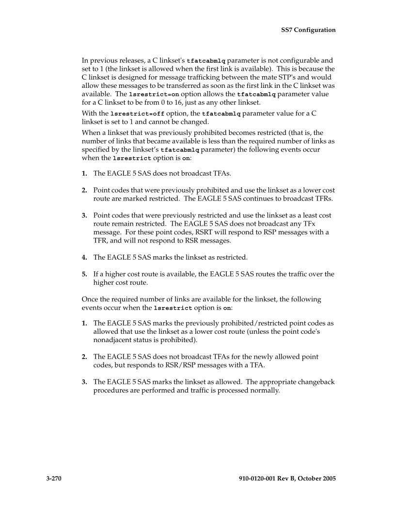
3-270 910-0120-001 Rev B, October 2005
SS7 Configuration
In previous releases, a C linkset's tfatcabmlq parameter is not configurable and set to 1 (the linkset is allowed when the first link is available). This is because the C linkset is designed for message trafficking between the mate STP's and would allow these messages to be transferred as soon as the first link in the C linkset was available. The lsrestrict=on option allows the tfatcabmlq parameter value for a C linkset to be from 0 to 16, just as any other linkset.
With the lsrestrict=off option, the tfatcabmlq parameter value for a C linkset is set to 1 and cannot be changed.
When a linkset that was previously prohibited becomes restricted (that is, the number of links that became available is less than the required number of links as specified by the linkset’s tfatcabmlq parameter) the following events occur when the lsrestrict option is on:
1. The EAGLE 5 SAS does not broadcast TFAs.
2. Point codes that were previously prohibited and use the linkset as a lower cost route are marked restricted. The EAGLE 5 SAS continues to broadcast TFRs.
3. Point codes that were previously restricted and use the linkset as a least cost route remain restricted. The EAGLE 5 SAS does not broadcast any TFx message. For these point codes, RSRT will respond to RSP messages with a TFR, and will not respond to RSR messages.
4. The EAGLE 5 SAS marks the linkset as restricted.
5. If a higher cost route is available, the EAGLE 5 SAS routes the traffic over the higher cost route.
Once the required number of links are available for the linkset, the following events occur when the lsrestrict option is on:
1. The EAGLE 5 SAS marks the previously prohibited/restricted point codes as allowed that use the linkset as a lower cost route (unless the point code's nonadjacent status is prohibited).
2. The EAGLE 5 SAS does not broadcast TFAs for the newly allowed point codes, but responds to RSR/RSP messages with a TFA.
3. The EAGLE 5 SAS marks the linkset as allowed. The appropriate changeback procedures are performed and traffic is processed normally.

SS7 Configuration
910-0120-001 Rev B, October 2005 3-271
Canceling the RTRV-LS Command
Because the rtrv-ls command used in this procedure can output information for a long period of time, the rtrv-ls command can be canceled and the output to the terminal stopped. There are three ways that the rtrv-ls command can be canceled.
• Press the F9 function key on the keyboard at the terminal where the rtrv-ls command was entered.
• Enter the canc-cmd without the trm parameter at the terminal where the rtrv-ls command was entered.
• Enter the canc-cmd:trm=<xx>, where <xx> is the terminal where the rtrv-ls command was entered, from another terminal other that the terminal where the rtrv-ls command was entered. To enter the canc-cmd:trm=<xx> command, the terminal must allow Security Administration commands to be entered from it and the user must be allowed to enter Security Administration commands. The terminal’s permissions can be verified with the rtrv-secu-trm command. The user’s permissions can be verified with the rtrv-user or rtrv-secu-user commands.
For more information about the canc-cmd command, go to the Commands Manual.
Procedure
1. Display the existing value for the lsrestrict parameter by entering the rtrv-ss7opts command. This is an example of the possible output.rlghncxa03w 05-09-17 16:02:05 GMT EAGLE5 34.0.0
SS7 OPTIONS-----------------------LSRESTRICT off
NOTE: The rtrv-ss7opts command output contains other fields that are not used by this procedure. If you wish to see all the fields displayed by the rtrv-ss7opts command, see the rtrv-ss7opts command description in the Commands Manual.
NOTE: If the lsrestrict parameter value in step 1 is off, skip steps 2 and 3, and go to step 4.
2. Display the linksets in the database by entering the rtrv-ls command. This is an example of the possible output.
rlghncxa03w 05-09-10 11:43:04 GMT EAGLE5 34.0.0 L3T SLT GWS GWS GWSLSN APCA (SS7) SCRN SET SET BEI LST LNKS ACT MES DIS SLSCI NISe1e2 001-207-000 none 1 1 no B 6 off off off no offls05 002-009-003 scr2 1 1 no C 4 on off on no offls1305 000-005-000 none 1 1 no A 1 off off off no offls1307 000-007-000 none 1 1 no A 1 off off off no offe1m1s1 001-001-001 none 1 1 no A 7 off off off no off

3-272 910-0120-001 Rev B, October 2005
SS7 Configuration
e1m1s2 001-001-002 none 1 1 no A 7 off off off no off
L3T SLT GWS GWS GWSLSN APCA (X25) SCRN SET SET BEI LST LNKS ACT MES DIS SLSCI NIS
L3T SLT GWS GWS GWSLSN APCI (SS7) SCRN SET SET BEI LST LNKS ACT MES DIS SLSCI NISe1e2i 1-207-0 none 1 1 no B 4 off off off --- onls1315 0-015-0 none 1 1 no A 1 off off off --- offls1317 0-017-0 none 1 1 no A 1 off off off --- one1m2s1 1-011-1 none 1 1 no A 7 off off off --- offe1m2s2 1-011-2 none 1 1 no A 7 off off off --- off
L3T SLT GWS GWS GWSLSN APCN (SS7) SCRN SET SET BEI LST LNKS ACT MES DIS SLSCI NIS
L3T SLT GWS GWS GWSLSN APCN24 (SS7) SCRN SET SET BEI LST LNKS ACT MES DIS SLSCI NIS
L3T SLT GWS GWS GWSLSN (CHINA) APCN (SS7) SCRN SET SET BEI LST LNKS ACT MES DIS SLSCI NIS
L3T SLT GWS GWS GWSLSN (CHINA) APCN24 (SS7) SCRN SET SET BEI LST LNKS ACT MES DIS SLSCI NIS
Link set table is (11 of 1024) 1% full.
NOTE: If there are no C linksets (linksets with the value C in the LST column) shown in the rtrv-ls output in step 2, skip step 3 and go to step 4.
3. Change the tfatcabmlq parameter value for one of the C linksets shown in step 2 to 0 using the chg-ls command. For this example, enter this command.
chg-ls:lsn=ls05:tfatcabmlq=0
When this command has successfully completed, this message should appear.
rlghncxa03w 05-09-07 08:38:45 GMT EAGLE5 34.0.0Link set table is ( 11 of 1024) 1% fullCHG-LS: MASP A - COMPLTD
After the chg-ls command has been performed, repeat step 3 with the name of another C linkset shown in step 2.
When all the C linksets have been changed, go to step 4.
NOTE: When the tfatcabmlq parameter is set to 0, its value in the rtrv-ls:lsn=<linkset name> output is shown as 1/2 of the number of signaling links contained in the linkset.
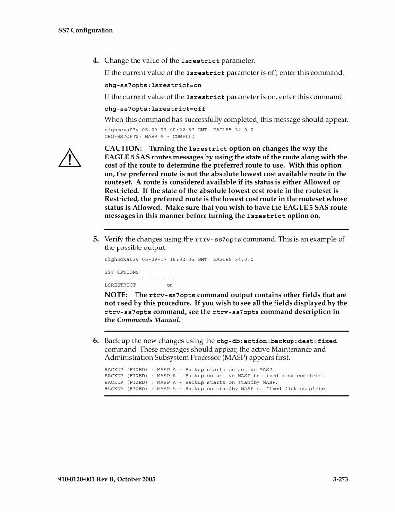
SS7 Configuration
910-0120-001 Rev B, October 2005 3-273
4. Change the value of the lsrestrict parameter.
If the current value of the lsrestrict parameter is off, enter this command.
chg-ss7opts:lsrestrict=on
If the current value of the lsrestrict parameter is on, enter this command.
chg-ss7opts:lsrestrict=off
When this command has successfully completed, this message should appear.rlghncxa03w 05-09-07 00:22:57 GMT EAGLE5 34.0.0CHG-SS7OPTS: MASP A - COMPLTD
CAUTION: Turning the lsrestrict option on changes the way the EAGLE 5 SAS routes messages by using the state of the route along with the cost of the route to determine the preferred route to use. With this option on, the preferred route is not the absolute lowest cost available route in the routeset. A route is considered available if its status is either Allowed or Restricted. If the state of the absolute lowest cost route in the routeset is Restricted, the preferred route is the lowest cost route in the routeset whose status is Allowed. Make sure that you wish to have the EAGLE 5 SAS route messages in this manner before turning the lsrestrict option on.
5. Verify the changes using the rtrv-ss7opts command. This is an example of the possible output.
rlghncxa03w 05-09-17 16:02:05 GMT EAGLE5 34.0.0
SS7 OPTIONS-----------------------LSRESTRICT on
NOTE: The rtrv-ss7opts command output contains other fields that are not used by this procedure. If you wish to see all the fields displayed by the rtrv-ss7opts command, see the rtrv-ss7opts command description in the Commands Manual.
6. Back up the new changes using the chg-db:action=backup:dest=fixed command. These messages should appear, the active Maintenance and Administration Subsystem Processor (MASP) appears first.
BACKUP (FIXED) : MASP A - Backup starts on active MASP.BACKUP (FIXED) : MASP A - Backup on active MASP to fixed disk complete.BACKUP (FIXED) : MASP A - Backup starts on standby MASP.BACKUP (FIXED) : MASP A - Backup on standby MASP to fixed disk complete.
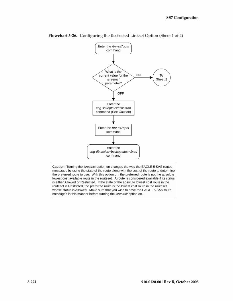
3-274 910-0120-001 Rev B, October 2005
SS7 Configuration
Flowchart 3-26. Configuring the Restricted Linkset Option (Sheet 1 of 2)

SS7 Configuration
910-0120-001 Rev B, October 2005 3-275
Flowchart 3-26. Configuring the Restricted Linkset Option (Sheet 2 of 2)
Enter thechg-ss7opts:lsrestrict=off
command
Enter the rtrv-ss7optscommand
Enter thechg-db:action=backup:dest=fixed
command
FromSheet 1
Enter the rtrv-lscommand
Are any C linksetsshown in the rtrv-ls output(linksets with the LST=C
parameter)?
No
Yes
Have all theC linksets been
changed?
Yes
No
Enter the chg-ls commandwith these parameters:
:lsn=<linkset name from theprevious rtrv-ls output>
:tfatcabmlq=0

3-276 910-0120-001 Rev B, October 2005
SS7 Configuration
Configuring the Options for Handling TFCs on ITU-I and ITU-N Networks
This procedure is used to configure the options for handling TFCs on ITU-I and ITU-N networks using the chg-ss7opts command with these two parameters:
:discardtfci – This parameter specifies that the EAGLE 5 SAS discards TFC traffic received from an ITU-I network (discardtfci=on), or does not discard TFC traffic received from an ITU-I network (discardtfci=off). The system default value for this parameter is off.
:discardtfcn – This parameter specifies that the EAGLE 5 SAS discards TFC traffic received from an ITU-N network (discardtfcn=on), or does not discard TFC traffic received from an ITU-N network (discardtfcn=off). The system default value for this parameter is off.
Procedure
1. Display the existing values for the discardtfci and discardtfcn parameters by entering the rtrv-ss7opts command. This is an example of the possible output.rlghncxa03w 05-09-17 16:02:05 GMT EAGLE5 34.0.0
SS7 OPTIONS-----------------------DISCARDTFCI offDISCARDTFCN off
NOTE: The rtrv-ss7opts command output contains other fields that are not used by this procedure. If you wish to see all the fields displayed by the rtrv-ss7opts command, see the rtrv-ss7opts command description in the Commands Manual.

SS7 Configuration
910-0120-001 Rev B, October 2005 3-277
2. Change the value of the discardtfci and discardtfcn parameters.
The values of these parameters is either on or off. The value specified in this step cannot be the same as the value shown in step 1.
If you wish to change the value of the discardtfci parameter, specify the discardtfci parameter with the chg-ss7opts command. For this example, enter this command.
chg-ss7opts:discardtfci=on
If you wish to change the value of the discardtfcn parameter, specify the discardtfcn parameter with the chg-ss7opts command. For this example, enter this command.
chg-ss7opts:discardtfcn=on
If you wish to change the value of both the discardtfci and discardtfcn parameters, specify the discardtfci and discardtfcn parameters with the chg-ss7opts command. For this example, enter this command.
chg-ss7opts:discardtfci=on:discardtfcn=on
When this command has successfully completed, this message should appear.rlghncxa03w 05-09-07 00:22:57 GMT EAGLE5 34.0.0CHG-SS7OPTS: MASP A - COMPLTD
3. Verify the changes using the rtrv-ss7opts command. This is an example of the possible output.
rlghncxa03w 05-09-17 16:02:05 GMT EAGLE5 34.0.0
SS7 OPTIONS-----------------------DISCARDTFCI onDISCARDTFCN on
NOTE: The rtrv-ss7opts command output contains other fields that are not used by this procedure. If you wish to see all the fields displayed by the rtrv-ss7opts command, see the rtrv-ss7opts command description in the Commands Manual.
4. Back up the new changes using the chg-db:action=backup:dest=fixed command. These messages should appear, the active Maintenance and Administration Subsystem Processor (MASP) appears first.
BACKUP (FIXED) : MASP A - Backup starts on active MASP.BACKUP (FIXED) : MASP A - Backup on active MASP to fixed disk complete.BACKUP (FIXED) : MASP A - Backup starts on standby MASP.BACKUP (FIXED) : MASP A - Backup on standby MASP to fixed disk complete.

3-278 910-0120-001 Rev B, October 2005
SS7 Configuration
Flowchart 3-27. Configuring the Options for Handling TFCs on ITU-I and ITU-N Networks

SS7 Configuration
910-0120-001 Rev B, October 2005 3-279
Changing the HC MIM Temperature Alarm Thresholds
This procedure is used to change the temperature alarm thresholds for the HC MIMs using the chg-th-alm command and these parameters.
:thermallv1c – The Celsius temperature threshold, from 60 to 76 degrees Celsius, at which major alarm UAM 0078 is generated. UAM 0078 is generated to alert the user that corrective action needs to be performed to prevent the HC MIM from overheating.
:thermallv2c – The Celsius temperature threshold, from 61 to 82 degrees Celsius, at which critical alarm UAM 0077 is generated. When this threshold is reached, the HC MIM is powered down, and all traffic on the signalling links assigned to the HC MIM is lost.
:thermallv1f – The Fahrenheit temperature threshold, from 140 to 167 degrees Fahrenheit, at which major alarm UAM 0078 is generated. UAM 0078 is generated to alert the user that corrective action needs to be performed to prevent the HC MIM from overheating.
:thermallv2f – The Fahrenheit temperature threshold, from 142 to 180 degrees Fahrenheit, at which critical alarm UAM 0077 is generated. When this threshold is reached, the HC MIM is powered down, and all traffic on the signalling links assigned to the HC MIM is lost.
For more information on these alarms, go to the Maintenance Manual.
The chg-th-alm command contains other optional parameters. These parameters are not shown here because they are not necessary to provision the HC MIM temperature alarm thresholds. These parameters are explained in more detail in the Commands Manual.
Procedure
1. Display the current HC MIM temperature alarm thresholds in the database by entering the rtrv-th-alm command. This is an example of the possible output.
rlghncxa03w 05-09-28 09:12:36 GMT EAGLE5 34.0.0Thermal Alarm Level 1: 75 Degrees Celsius Thermal Alarm Level 2: 82 Degrees Celsius Command Executed
NOTE: The rtrv-th-alm command output contains other fields that are not used in this procedure. If you wish to see all the fields displayed by the rtrv-th-alm command, see the rtrv-th-alm command description in the Commands Manual.

3-280 910-0120-001 Rev B, October 2005
SS7 Configuration
2. Change the temperature alarm thresholds by entering the chg-th-alm command with at least one of the temperature alarm threshold parameters.
The temperature can be entered as a Fahrenheit temperature. The EAGLE 5 SAS converts the Fahrenheit temperature to a Celsius temperature. The temperature is displayed in the rtrv-th-alm output as a Celsius temperature.
If a Celsius temperature value is specified, the thermallv2c parameter value shown in the rtrv-th-alm output after the chg-th-alm command has been executed must be greater than the thermallv1c parameter value shown in the rtrv-th-alm output.
If both Fahrenheit temperature values are specified, the thermallv2f parameter value must be greater than the thermallv1f parameter value.
If only the thermallv1f parameter is specified, the thermallv1f parameter value must be less than the Fahrenheit equivalent of the thermallv2c parameter value shown in the rtrv-th-alm output.
If only the thermallv2f parameter is specified, the thermallv2f parameter value must be greater than the Fahrenheit equivalent of the thermallv1c parameter value shown in the rtrv-th-alm output.
If a temperature parameter is not specified with the chg-th-alm command, that parameter value will not be changed. The system default values for the temperature parameters are:
– :thermallv1c = 75
– :thermallv2c = 82
– :thermallv1f = 167
– :thermallv2f = 180.
NOTE: Values for the thermallv1f and thermallv2f parameters cannot be specified if these values convert to the same Celsius temperature value. For example, the thermallv1f=146 and thermallv2f=147 parameters cannot be specified because both values convert to 63 degrees Celsius.
For this example, enter this command.
chg-th-alm:thermallv1c=70:thermallv2c=77
If these temperature values are entered as Fahrenheit temperatures, enter this command.
chg-th-alm:thermallv1f=158:thermallv2f=171
When this command has successfully completed, this message should appear.
rlghncxa03w 05-09-28 09:12:36 GMT EAGLE5 34.0.0CHG-TH-ALM: MASP A - COMPLTD

SS7 Configuration
910-0120-001 Rev B, October 2005 3-281
3. Verify the changes using the rtrv-th-alm command. This is an example of the possible output.
rlghncxa03w 05-09-28 09:12:36 GMT EAGLE5 34.0.0Thermal Alarm Level 1: 70 Degrees Celsius Thermal Alarm Level 2: 77 Degrees Celsius Command Executed
NOTE: The rtrv-th-alm command output contains other fields that are not used in this procedure. If you wish to see all the fields displayed by the rtrv-th-alm command, see the rtrv-th-alm command description in the Commands Manual.
4. Backup the new changes using the chg-db:action=backup:dest=fixed command. These messages should appear, the active Maintenance and Administration Subsystem Processor (MASP) appears first.
BACKUP (FIXED) : MASP A - Backup starts on active MASP.BACKUP (FIXED) : MASP A - Backup on active MASP to fixed disk complete.BACKUP (FIXED) : MASP A - Backup starts on standby MASP.BACKUP (FIXED) : MASP A - Backup on standby MASP to fixed disk complete.

3-282 910-0120-001 Rev B, October 2005
SS7 Configuration
Flowchart 3-28. Changing the HC MIM Temperature Alarm Thresholds

910-0120-001 Rev B, October 2005 A-1
A
E1 Interface
Introduction.....................................................................................................A–2
Determining the Configuration....................................................................A–8
Adding a LIM-E1 Card ................................................................................A–14
Removing a LIM-E1 Card............................................................................A–24
Adding Channelized and non-Channel Bridged E1 Ports .....................A–28
Adding Channel Bridged E1 Ports.............................................................A–37
Adding Unchannelized E1 Ports ................................................................A–45
Removing the E1 Interface Parameters .....................................................A–59
Changing the Attributes of an E1 Port ......................................................A–62
Adding an E1 Signaling Link......................................................................A–77

A-2 910-0120-001 Rev B, October 2005
E1 Interface
Introduction
The E1 interface terminates or distributes E1 facility signals for the purpose of processing the SS7 signaling links carried by the E1 carrier. The E1 interface can be either a LIM-E1 card, an E1/T1 MIM card, or an HC MIM as shown in Figures A-1, A-2, and A-3. The E1/T1 MIM or HC MIM can also be used as a T1 interface. This appendix describes how an E1 interface is configured using either the LIM-E1 card, the E1/T1 MIM card, or HC MIM. The T1 interface configuration is described in Appendix B, “T1 Interface.”
NOTE: The procedures in this appendix are used only to configure E1 signaling links on the LIM-E1 card, E1/T1 MIM card, or HC MIM. To configure an E1 high-speed signaling link (on the LIME1ATM card), go to the “Adding an ATM High-Speed Signaling Link” procedure on page C-34.
The LIM-E1 card contains only two signaling links. The E1/T1 MIM card contains up to eight signaling links and allows the EAGLE 5 SAS to contain more than 500 signaling links.
Figure A-1. LIM-E1 Block Diagram
� $��
� 1�#���$���� "�$
� "���!�
(-�� "(����
�#���$�"%�*
�#���$� "���!�
������ "+�%
����
�
)
23��� "���%�*"
23��� "���%�*"
� $��
4��5�" �
�� ���
� 1�#���$���� "�$
� "���!�
(-�� "
(�����#���$�"%�*
�#���$� "���!�
������ "+�%
����
�
) �� ��
7������
�8�7������
�22-6� ��$,�
�22-6� ��$,�
79�� ,-�7�
�,��2-, .��2 ��0
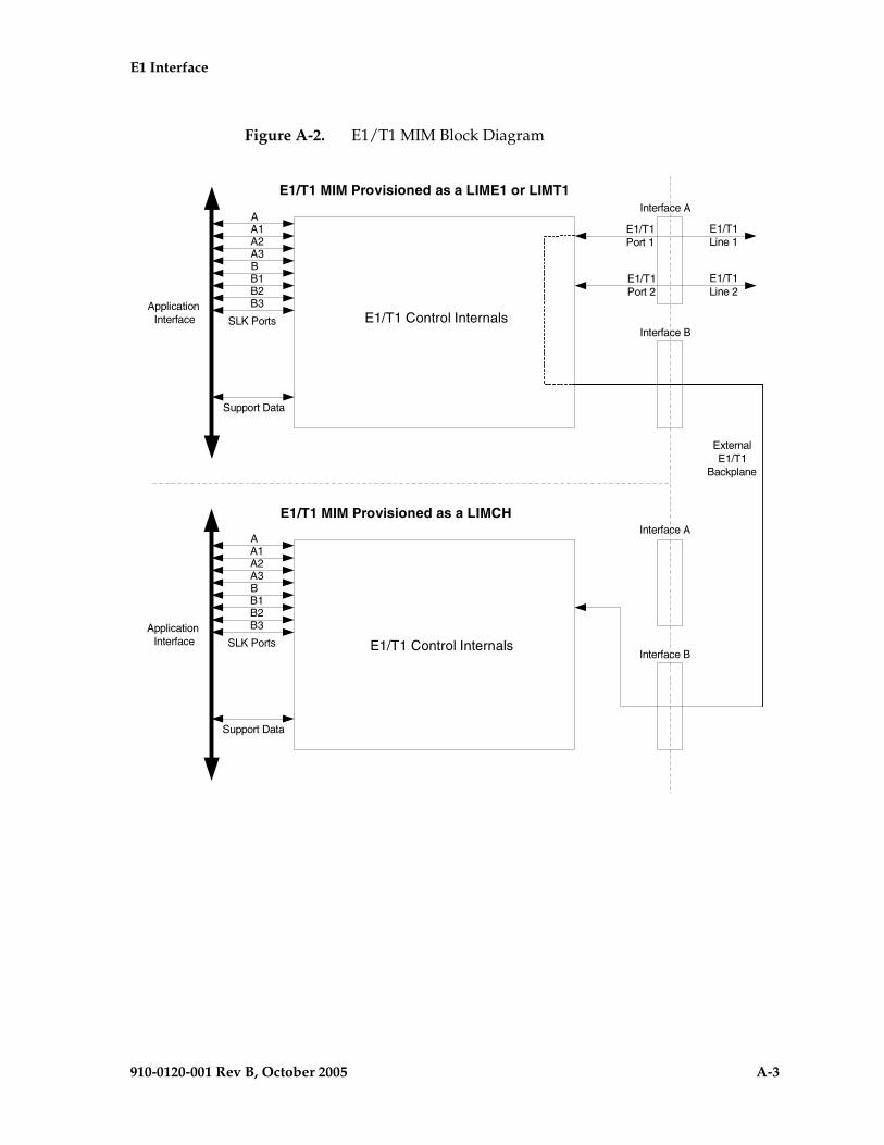
E1 Interface
910-0120-001 Rev B, October 2005 A-3
Figure A-2. E1/T1 MIM Block Diagram
E1/T1 Control Internals
A A1
B3 B2 B1
B A3 A2
SLK PortsApplication Interface
Support Data
Interface A
Interface B
E1/T1Port 1
E1/T1Port 2
E1/T1 Control Internals
A A1
B3 B2 B1
B A3 A2
SLK PortsApplication Interface
Support Data
Interface A
Interface B
ExternalE1/T1
Backplane
E1/T1 MIM Provisioned as a LIME1 or LIMT1
E1/T1 MIM Provisioned as a LIMCH
E1/T1Line 1
E1/T1Line 2

A-4 910-0120-001 Rev B, October 2005
E1 Interface
Figure A-3. HC MIM Block Diagram

E1 Interface
910-0120-001 Rev B, October 2005 A-5
Table A-1 provides an overview of the functions of the E1 card and the channel card.
Configured as an E1 Card
Configured as an E1 card, two separate and independent E1 inputs can be terminated on an E1 card. If a LIM-E1 card is being used, one or two bi-directional channels are extracted from the E1 inputs and processed as SS7 signaling links. If an E1/T1 MIM is being used, one to eight bi-directional channels are extracted from the E1 inputs and processed as SS7 signaling links. Implemented as E1 Link Interface Modules, up to thirty two separate and independent E1 inputs can be terminated in an Extension Shelf. The LIME1 card can support signaling links transmitting at either 56 kbps or 64 kbps.
Configured as a Channel Card
In an Extension shelf equipped with an E1 cabling backplane, an E1 card terminates one or two E1 inputs and connects the E1 port 1 input to one of eight available busses on the E1 cabling backplane. Channel cards also connected to the E1 cabling backplane are able to extract any eight (or two if a LIM-E1 card configured as a channel card is being used) signaling channels from the same E1 port 1 input. In this manner, up to 31 E1 channels can be used for signaling - the 32nd channel is reserved for E1 synchronization. The LIME1 card can support signaling links transmitting at either 56 kbps or 64 kbps.
NOTE: An HC MIM cannot be used as a channel card.
Table A-1. Functional Overview of the E1 and Channel Card
Card Function
E1
• Connectivity of both E1 interfaces to a 120 Ohm or 75 Ohm E1 interface. An external adapter is required for the 75 Ohm interface.
• Processing up to a total of eight (only two if a LIM-E1 card is being used) time slots from the E1 interfaces
• Interface E1 port 1 through an external backplane to channel cards for processing of additional time slots
Channel
• Processing up to eight (only two if a LIM-E1 card configured as a channel card is being used) time slots from the E1 interface
• Interface through an external backplane to an E1 card to process up to eight (only two if a LIM-E1 card configured as a channel card is being used) time slots

A-6 910-0120-001 Rev B, October 2005
E1 Interface
High Capacity Multi-Channel Interface Module (HC MIM)
The High Capacity Multi-Channel Interface Module (HC MIM) provides access to eight E1 ports residing on backplane connectors A and B. Each data stream consists of 31 E1 DS0 signaling links assigned in a time-division multiplex manner. Each channel occupies a unique timeslot in the data stream and can be selected as a local signaling link on the interface card. A maximum of 64 E1 signaling links can be assigned to an HC MIM.
To support the processing of signaling channels that are intermixed on trunks with voice or data channels, the HC MIM allows E1 ports to be channel bridged. This allows better utilization of E1 bandwidth without dedicating entire trunks to signaling.
Figure A-4. Channel Bridging
Channel bridging is implemented by pairing odd and even E1 ports. The E1 port selected for channel bridging is the odd numbered port (1, 3, 5, 7). When the E1 port is selected for channel bridging, it is paired with its adjacent even numbered port (2, 4, 6, 8) as shown in Table A-2.
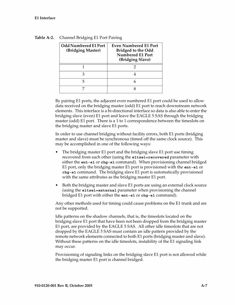
E1 Interface
910-0120-001 Rev B, October 2005 A-7
By pairing E1 ports, the adjacent even numbered E1 port could be used to allow data received on the bridging master (odd) E1 port to reach downstream network elements. This interface is a bi-directional interface so data is also able to enter the bridging slave (even) E1 port and leave the EAGLE 5 SAS through the bridging master (odd) E1 port. There is a 1 to 1 correspondence between the timeslots on the bridging master and slave E1 ports.
In order to use channel bridging without facility errors, both E1 ports (bridging master and slave) must be synchronous (timed off the same clock source). This may be accomplished in one of the following ways:
• The bridging master E1 port and the bridging slave E1 port use timing recovered from each other (using the e1tsel=recovered parameter with either the ent-e1 or chg-e1 command). When provisioning channel bridged E1 port, only the bridging master E1 port is provisioned with the ent-e1 or chg-e1 command. The bridging slave E1 port is automatically provisioned with the same attributes as the bridging master E1 port.
• Both the bridging master and slave E1 ports are using an external clock source (using the e1tsel=external parameter when provisioning the channel bridged E1 port with either the ent-e1 or chg-e1 command).
Any other methods used for timing could cause problems on the E1 trunk and are not be supported.
Idle patterns on the shadow channels, that is, the timeslots located on the bridging slave E1 port that have been not been dropped from the bridging master E1 port, are provided by the EAGLE 5 SAS. All other idle timeslots that are not dropped by the EAGLE 5 SAS must contain an idle pattern provided by the remote network elements connected to both E1 ports (bridging master and slave). Without these patterns on the idle timeslots, instability of the E1 signaling link may occur.
Provisioning of signaling links on the bridging slave E1 port is not allowed while the bridging master E1 port is channel bridged.
Table A-2. Channel Bridging E1 Port Pairing
Odd Numbered E1 Port (Bridging Master)
Even Numbered E1 Port Bridged to the Odd Numbered E1 Port (Bridging Slave)
1 2
3 4
5 6
7 8
A-8 910-0120-001 Rev B, October 2005
E1 Interface
Determining the Configuration
External Interface Descriptions
The E1 Interface Backplane provides a method for extending individual E1 channels from the E1-configured cards to any channel-configured cards in use. Note the following issues regarding the E1 backplane:
• Only one E1-configured card may be plugged into each bus on the backplane.
• When installing non-E1 cards on the shelf equipped with the E1 interface backplane, ensure that none of the slots to be used are cabled to the E1 interface backplane. If a non-E1 card is installed in a slot that is connected to the E1 backplane, all E1 cards on that bus may fail.
• Only one E1 card may be connected (via the B port) to each bus of the E1 cabling backplane, and all SS7 links derived from any particular E1 must be processed on the same shelf on which the incoming E1 is terminated.
• Due to cable congestion, Tekelec does not recommend use of the E1 cabling backplane on the control shelf.
• If the control shelf is used, a maximum of 20 E1 interfaces can be utilized in the control shelf.
The E1 backplane is impedance-controlled for 120 Ohms and is designed for use with RS-485 transmission characteristics.
Descriptions of the E1 hardware and the procedures for installing the E1 hardware are contained in the Hardware Manual - EAGLE 5 SAS and Installation Manual - EAGLE 5 SAS.
E1 Cards Containing DIP Switches
The EAGLE 5 SAS can contain E1 cards with DIP switches. These switches were used in previous releases to configure the E1 parameters that are now configured by these commands:
• ent-e1 – Adding E1 interface parameter information
• chg-e1 – Changing E1 interface parameter information
• ent-slk – Adding a signaling link.
In this release, these switches are not used and the settings on these switches are ignored by the EAGLE 5 SAS.

E1 Interface
910-0120-001 Rev B, October 2005 A-9
For more information on the ent-e1, chg-e1, and ent-slk commands, go to the Commands Manual, or see these procedures in this appendix:
• “Adding Channelized and non-Channel Bridged E1 Ports” procedure on page A-28
• “Changing the Attributes of an E1 Port” procedure on page A-62
• “Adding an E1 Signaling Link” procedure on page A-77.
The procedure for removing an E1 signaling link is the same as removing an SS7 signaling link, so to remove an E1 signaling link from the database, go to the “Removing an SS7 Signaling Link” procedure on page 3-145.
Possible Configurations
The E1 backplane was designed to allow the maximum number of possible customer setups. It allows the customer to choose between several levels of diversity and convenience. Configurations depend on the number of cards configured as E1 cards versus the number of cards configured as channel cards. The level of diversity required by the customer also affects the configuration requirements. Note that all signals labelled “E1 input” may be one or two E1 ports depending on the cable used.
Support of Two E1 Ports
The E1 card will support two E1 ports, which are independently configurable. On an E1 card, E1 port 1 will support channel cards. The second port of that E1 card will only support up to a maximum of eight (two for a LIM-E1 card) time slots and will not support channel cards.
Clocking Options
Each E1 interface must independently operate in one of two clocking modes. When configured as a channel card, an E1 card is required for the channel card’s clocking source.
• Slave Timing - The default receive clock on the LIM-E1 card will be used as the source of the transmit clock.
• Master Timing - The transmit clock of the LIM-E1 card will originate on this board. The oscillator on the board provides the clock source. Note the oscillator is less accurate than the network clock.
The Master Timing feature allows an E1 signaling link to take its high-speed clock reference directly from an external high-speed master clock source.
A-10 910-0120-001 Rev B, October 2005
E1 Interface
Support of E1 Framing Options
The E1 interfaces will independently support the following E1 framing options. Selection of these options will be made by the crc4 and cas parameters of either the ent-e1 or chg-e1 commands.
• Clear Channel Signaling (CCS)
• Channel Associated Signaling (CAS)
• Cyclic Redundancy Check (CRC4)
The following provide for zero bit suppression: HDB-3 (High Density Bipolar encoding of order 3).
On any given E1 card, CCS and CAS are mutually exclusive and cannot be used together. However, CRC4 may be added to either CCS or CAS.
LIM-E1 Card to Channel Card Interface
Whether the E1/channel card is operating as an E1 card or a channel card, the card will map any eight channels (only 2 channels when the LIM-E1/channel card is being used) from the E1 interfaces to an HDLC controller (ports A, B, A1, B1, A2, B2, A3, B3 for the E1/T1 MIM card, or ports A and B for the LIM-E1 card). These channels could be dropped either both from E1 port 1 or one from E1 port 1 and the other from E1 port 2. When the E1/channel card is configured as an E1 card, it will support the external E1 cabling backplane interface from E1 port 1 (E1 port 2 will not have this capability) to additional E1/channel cards, within the same shelf, configured as channel cards. Idle time slots not assigned to an E1 card or a channel card will be filled with a one’s pattern.
Channel Support
The E1/channel card will independently support either 56 kbps or 64 kbps on any channel.
Configuring the Signaling Links
The main consideration for the provisioning of E1s is to determine the number of E1s existing in the network and the equipment needed for grooming into the EAGLE 5 SAS. To utilize the flexibility of the E1 interface feature, you may want to determine the minimum number of E1 cards needed to process the total number of SS7 links and then consider diversity for reliability reasons.

E1 Interface
910-0120-001 Rev B, October 2005 A-11
Use the following points as guidelines when considering diversity for E1:
• If possible, no two E1s containing links from a common link set should be on the same E1/dual port channel card.
• If possible, no two E1s containing links from a common link set should be on adjacent E1/dual port channel cards where they are powered from the same fuse position.
• If possible, no two E1s containing links from a common link set should be terminated on the same shelf because of the shelf clock cabling, and is only an issue if using master clocking sync to the network
• If possible, no two links in a link set should arrive at the EAGLE 5 SAS on the same E1.
• If possible, for link sets containing more than two links, you should minimize the number of links in that link set on any given E1.
• Customers may also wish to mix the LIM V.35 or LIM OCU in any shelf as needed for site requirements.
As an example, consider a network to be groomed into the EAGLE 5 SAS consisting of 30 E1s with a total number of 100 links where the largest link set size is 8. The most efficient way to provision the EAGLE 5 SAS would be to have four extension shelves equipped with the E1 cabling backplane, one E1 card, and 12 channel cards per shelf. Utilizing one B bus on each shelf, 25 signaling links would be terminated on each shelf for a total of 100. This is also the minimum number of E1 cards required for this example.
With the same example but using the third and fifth bullets above as a consideration, the EAGLE 5 SAS would be provisioned with eight extension shelves equipped with the E1 cabling backplane. Four of the shelves would be equipped with one E1 card and six channel cards, and the other four shelves would be equipped with one E1 card and five channel cards. Since the largest link set size is eight, a total of eight E1 cards is required. Utilizing one B bus on each shelf, 13 signaling links would be terminated on each shelf with six channel cards, and 12 signaling links would be terminated on each shelf with five channel cards.
NOTE: When retrieving link information from the database, the links for an E1 or channel card is not displayed until after the card is allowed.

A-12 910-0120-001 Rev B, October 2005
E1 Interface
E1 Configuration Form
Use the form provided below to record your E1 configuration. An example of the required input is shown in italics under each column heading.
Table A-3. E1 Signaling Link Configuration Form
Card Location and Port (1201 A)
Timeslot (1)
E1 Number
(1)
E1 Card Location
(1201)
Adjacent Point Code
(4001)
Linkset (ST1ME)
SLC (1)

E1 Interface
910-0120-001 Rev B, October 2005 A-13
E1 Interface Configuration Procedures
This appendix contains these procedures because they contain information specific to the E1 Interface:
• “Adding a LIM-E1 Card” on page A-14
• “Removing a LIM-E1 Card” on page A-24
• “Adding Channelized and non-Channel Bridged E1 Ports” on page A-28
• “Adding Channel Bridged E1 Ports” on page A-37
• “Adding Unchannelized E1 Ports” on page A-45
• “Removing the E1 Interface Parameters” on page A-59
• “Changing the Attributes of an E1 Port” on page A-62
• “Adding an E1 Signaling Link” on page A-77
Procedures for configuring the linksets and routes, for removing SS7 signaling links (which includes E1 signaling links), and for configuring the HC MIM temperature alarms are contained in Chapter 3, “SS7 Configuration.” These procedures contain no information that is specific to the E1 interface, therefore, are not included in this appendix.
The procedures contained in this appendix use a variety of commands. If more information on these commands is needed, go to the Commands Manual to find the required information.

A-14 910-0120-001 Rev B, October 2005
E1 Interface
Adding a LIM-E1 Card
The LIM-El card is provisioned in the database using the ent-card command. This card can be provisioned as either an E1 card or a channel card. The card being provisioned in the database can be one of these cards shown in Table A-4.
The ent-card command uses these parameters.
:loc – The location of the card being added to the database.
NOTE: The HC MIM can be inserted only in a odd-numbered card location. The HC MIM will not power up if it is inserted in an even-numbered card location. All the E1 backplane cabling should be removed from the B connector for the slot that the HC MIM will occupy.
The HC MIM occupies two card locations, so the even numbered card location adjacent to the odd numbered slot where the HC MIM has been inserted must be empty, as shown in Table A-5. The HC MIM is connected to the network through the odd numbered card slot connector.
:type – The type of card being added to the database. For this procedure, the value of this parameter is lime1 (E1 card) or limch (channel card).
NOTE: The HC MIM cannot be provisioned as a channel card.
:appl – The application software or GPL that is assigned to the card. For this procedure, the value of this parameter is either ccs7itu or ss7ansi.
:force – Allow the LIM to be added to the database even if there are not enough cards running the SCCP GPL (TSM) or running the VSCCP GPL (DSM) in the EAGLE 5 SAS to support the number of LIMs in the EAGLE 5 SAS. This parameter is obsolete and is no longer used.
Table A-4. E1 Card Part Numbers
Card Type Part Number
LIM-E1 870-1379-XX
E1/T1 MIM 870-2198-XX
HC MIM 870-2671-01
Table A-5. HC MIM Card Locations
Location of the HC MIM
Empty Card Location
Location of the HC MIM
Empty Card Location
Slot 01 Slot 02 Slot 11 Slot 12
Slot 03 Slot 04 Slot 13 Slot 14
Slot 05 Slot 06 Slot 15 Slot 16
Slot 07 Slot 08 Slot 17 Slot 18

E1 Interface
910-0120-001 Rev B, October 2005 A-15
The shelf to which the card is to be added, must already be in the database. This can be verified with the rtrv-shlf command. If the shelf is not in the database, see the “Adding a Shelf” procedure in the Database Administration Manual - System Management.
If an HC MIM is being provisioned in this procedure, the FAN feature must be turned on. If the FAN feature is not turned on, the HC MIM will be auto-inhibited when the HC MIM is inserted into the shelf. The status of the FAN feature is shown in the rtrv-feat command output.
If an HC MIM is being provisioned in this procedure, HIPR cards must be installed into card locations 9 and 10 in the shelf that the HC MIM will occupy. If HIPR cards are not installed in the shelf that the HC MIM will occupy, the HC MIM will be auto-inhibited when the HC MIM is inserted into the shelf. Enter the rept-stat-gpl:gpl=hipr command to verify whether or not HIPR cards are installed in the same shelf as the HC MIM being provisioned in this procedure.
The examples in this procedure are used to add the LIM-E1 cards in card locations 1201, 1202, 1203, 1204, 1211, and 1212 to the database.
Procedure
1. Display the cards in the EAGLE 5 SAS using the rtrv-card command. This is an example of the possible output.
rlghncxa03w 05-09-28 09:12:36 GMT EAGLE5 34.0.0CARD TYPE APPL LSET NAME LINK SLC LSET NAME LINK SLC1101 TSM SCCP 1102 TSM GLS 1113 GSPM EOAM1114 TDM-A1115 GSPM EOAM1116 TDM-B1117 MDAL1305 LIMOCU CCS7ITU sp6 A 0 sp7 B 01306 LIMOCU CCS7ITU nsp3 A 0 nsp4 B 01307 LIMOCU CCS7ITU nsp1 A 0 1308 LIMOCU CCS7ITU nsp1 A 1 1316 ACMENET STPLAN 1314 LIMOCU CCS7ITU sp7 A 1 sp5 B 01317 TSM SCCP
The cards should be distributed throughout the EAGLE 5 SAS for proper power distribution. Refer to the Installation Manual - EAGLE 5 SAS for the shelf power distribution.
2. Verify that the correct hardware has been installed on the EAGLE 5 SAS to support the LIM-E1 card as shown in the Installation Manual - EAGLE 5 SAS.

A-16 910-0120-001 Rev B, October 2005
E1 Interface
3. Physically verify that the E1 card has been installed into the card location that will be specified in step 8. If the E1 card is an HC MIM, make sure the HC MIM is installed according to the card location requirements shown in Table A-5 on page A-14. If a card is installed and provisioned in the even numbered card location adjacent to the desired odd numbered card, either choose another card location to install and provision the HC MIM, or remove the card in the even-numbered card location by performing the appropriate procedure shown in Table A-6.
NOTE: Channel cards must be installed in the same shelf as the E1 card that is servicing the timeslots on those channel cards.
Table A-6. Card Removal Procedures
Card Application Procedure
SS7ANSI, ATMANSI, CCS7ITU, ATMITU
“Removing an SS7 LIM” in Chapter 4, “System Configuration Procedures” in the Database Administration Manual - System Management. “Removing a LIM-E1 Card” on page A-24“Removing a LIM-T1 Card” on page B-20
SS7GX25 “Removing an X.25 LIM” in Chapter 2, “X.25 Gateway Configuration,” in the Database Administration Manual - Features
SCCP “Removing an SCCP Card” in Chapter 2, “Global Title Translation (GTT) Configuration,”in the Database Administration Manual - Global Title Translation“Removing an SCCP Card” in the LNP Feature Activation Guide
VSCCP
GLS “Removing a GLS Card” in Chapter 2, “Gateway Screening (GWS) Overview,” in the Database Administration Manual - Gateway Screening
STPLAN, VXWSLAN “Removing an STP LAN Card” in Chapter 3, “STP LAN Configuration,” in the Database Administration Manual - Features
EBDADCM “Removing the DCM Applied to LSMS BLM-Based Operations” in the LNP Feature Activation Guide
EBDABLM “Removing the BLM Applied to LSMS BLM-Based Operations” in the LNP Feature Activation Guide
IPLIM, IPLIMI, SS7IPGW, IPGWI
“Removing an IP Card” in Chapter 3, “IP7 Secure Gateway Configuration Procedures,” in the Database Administration Manual - IP7 Secure Gateway
EROUTE“Removing an STC Card” in Chapter 6, “Eagle Support for Integrated Sentinel Configuration,” in the Database Administration Manual - Features
MCP“Removing an MCPM” in Chapter 4, “System Configuration Procedures” in the Database Administration Manual - System Management.
IPS“Removing an IPSM” in Chapter 4, “System Configuration Procedures” in the Database Administration Manual - System Management.
E1 Interface
910-0120-001 Rev B, October 2005 A-17
NOTE: If the LIM-E1 card being added in this procedure is not an HC MIM, skip steps 4 through 7 and go to step 8.
4. Verify whether or not that the Fan feature is on, by entering the rtrv-feat command. If the global title translation feature is on, the entry FAN = on appears in the rtrv-feat command output.
NOTE: The rtrv-feat command output contains other fields that are not used by this procedure. If you wish to see all the fields displayed by the rtrv-feat command, see the rtrv-feat command description in the Commands Manual.
If the Fan feature is on, skip step 5, and go to step 6.
5. Turn the Fan feature on by entering this command.
chg-feat:fan=on
NOTE: Once the Fan feature is turned on with the chg-feat command, it cannot be turned off.
The Fan feature must be purchased before you turn this feature on with the chg-feat command. If you are not sure if you have purchased the Fan feature, contact your Tekelec Sales Representative or Account Representative.
When the chg-feat has successfully completed, this message appears.
rlghncxa03w 05-09-28 11:43:04 GMT EAGLE5 34.0.0CHG-FEAT: MASP A - COMPLTD
6. The shelf containing the HC MIM being added in this procedure must have fans installed. Verify whether or not fans are installed on the shelf.
If the fans are installed, go to step 7.
If the fans are not installed on the shelf containing the HC MIM, go to the Installation Manual - EAGLE 5 SAS and install the fans. Once the fans have been installed and tested, go to step 7. The fans must be working properly before an HC MIM can be placed in the EAGLE 5 SAS.

A-18 910-0120-001 Rev B, October 2005
E1 Interface
7. Verify that HIPR cards are installed in card locations 9 and 10 in the shelf containing the HC MIM being added in this procedure. Enter this command.
rept-stat-gpl:gpl=hipr
This is an example of the possible output.
rlghncxa03w 05-09-01 11:40:26 GMT EAGLE5 34.0.0GPL CARD RUNNING APPROVED TRIALHIPR 1109 125-002-000 125-002-000 125-003-000HIPR 1110 125-002-000 125-002-000 125-003-000HIPR 1209 125-002-000 125-002-000 125-003-000HIPR 1210 125-002-000 125-002-000 125-003-000HIPR 1309 125-002-000 125-002-000 125-003-000HIPR 1310 125-002-000 125-002-000 125-003-000HIPR 2109 125-002-000 125-002-000 125-003-000HIPR 2110 125-002-000 125-002-000 125-003-000Command Completed
If HIPR cards are installed in the shelf containing the HC MIM, go to step 8.
If HIPR cards are not installed on the shelf containing the HC MIM, go to the Installation Manual - EAGLE 5 SAS and install the HIPR cards. Once the HIPR cards have been installed, go to step 8.
8. Add the card using the ent-card command. If the LIM-E1 card is an HC MIM, the HC MIM can be only in a odd-numbered card location, and cannot be provisioned as a channel card.
For this example, enter these commands.ent-card:loc=1201:type=lime1:appl=ccs7itu
ent-card:loc=1202:type=limch:appl=ccs7itu
ent-card:loc=1203:type=lime1:appl=ccs7itu
ent-card:loc=1204:type=limch:appl=ccs7itu
ent-card:loc=1211:type=lime1:appl=ccs7itu
ent-card:loc=1212:type=limch:appl=ccs7itu
When each of these commands have successfully completed, this message should appear.rlghncxa03w 05-09-12 09:12:36 GMT EAGLE5 34.0.0ENT-CARD: MASP A - COMPLTD

E1 Interface
910-0120-001 Rev B, October 2005 A-19
9. Verify the changes using the rtrv-card command with the card location specified in step 8. For this example, enter these commands.
rtrv-card:loc=1201
This is an example of the possible output.rlghncxa03w 05-09-28 09:12:36 GMT EAGLE5 34.0.0CARD TYPE APPL LSET NAME LINK SLC LSET NAME LINK SLC1201 LIME1 CCS7ITU
rtrv-card:loc=1202
This is an example of the possible output.rlghncxa03w 05-09-28 09:12:36 GMT EAGLE5 34.0.0CARD TYPE APPL LSET NAME LINK SLC LSET NAME LINK SLC1202 LIMCH CCS7ITU
rtrv-card:loc=1203
This is an example of the possible output.rlghncxa03w 05-09-28 09:12:36 GMT EAGLE5 34.0.0CARD TYPE APPL LSET NAME LINK SLC LSET NAME LINK SLC1203 LIME1 CCS7ITU
rtrv-card:loc=1204
This is an example of the possible output.rlghncxa03w 05-09-28 09:12:36 GMT EAGLE5 34.0.0CARD TYPE APPL LSET NAME LINK SLC LSET NAME LINK SLC1204 LIMCH CCS7ITU
rtrv-card:loc=1211
This is an example of the possible output.rlghncxa03w 05-09-28 09:12:36 GMT EAGLE5 34.0.0CARD TYPE APPL LSET NAME LINK SLC LSET NAME LINK SLC1211 LIME1 CCS7ITU
rtrv-card:loc=1212
This is an example of the possible output.rlghncxa03w 05-09-28 09:12:36 GMT EAGLE5 34.0.0CARD TYPE APPL LSET NAME LINK SLC LSET NAME LINK SLC1212 LIMCH CCS7ITU
10. Backup the new changes using the chg-db:action=backup:dest=fixed command. These messages should appear, the active Maintenance and Administration Subsystem Processor (MASP) appears first.
BACKUP (FIXED) : MASP A - Backup starts on active MASP.BACKUP (FIXED) : MASP A - Backup on active MASP to fixed disk complete.BACKUP (FIXED) : MASP A - Backup starts on standby MASP.BACKUP (FIXED) : MASP A - Backup on standby MASP to fixed disk complete.
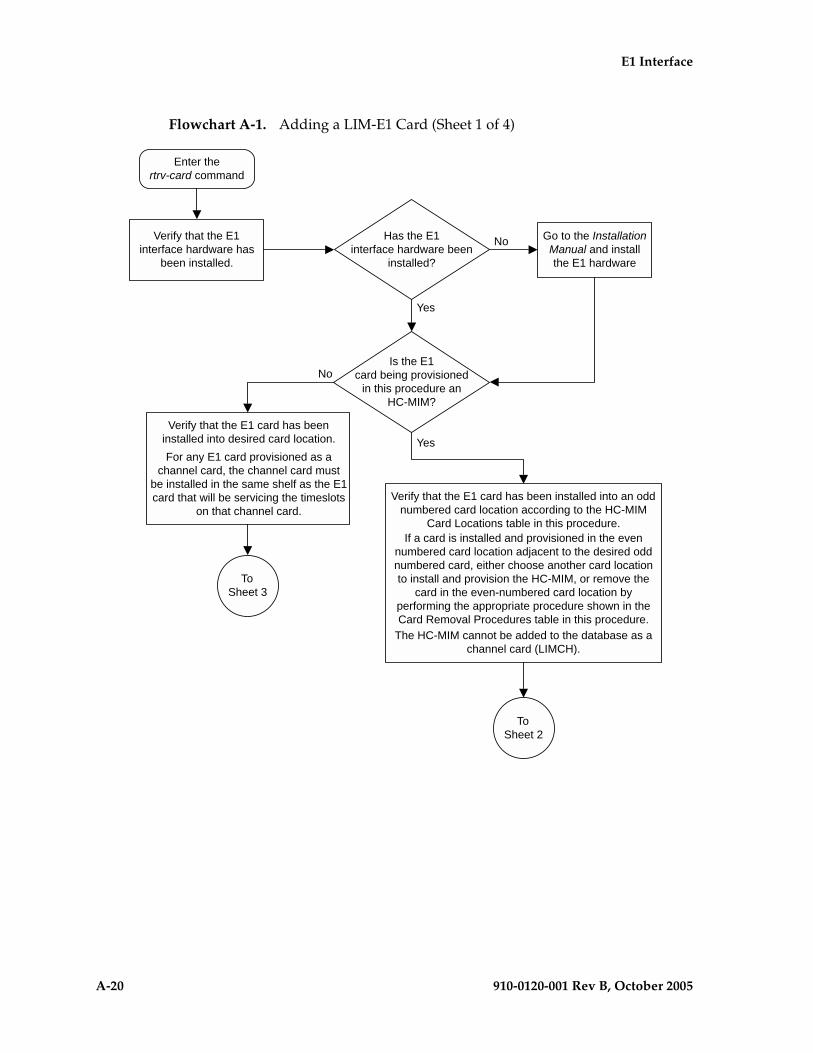
A-20 910-0120-001 Rev B, October 2005
E1 Interface
Flowchart A-1. Adding a LIM-E1 Card (Sheet 1 of 4)

E1 Interface
910-0120-001 Rev B, October 2005 A-21
Flowchart A-1. Adding a LIM-E1 Card (Sheet 2 of 4)

A-22 910-0120-001 Rev B, October 2005
E1 Interface
Flowchart A-1. Adding a LIM-E1 Card (Sheet 3 of 4)
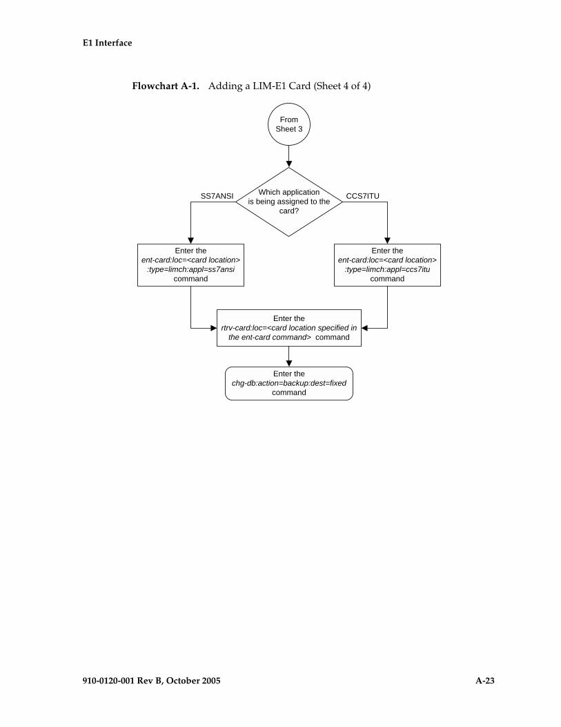
E1 Interface
910-0120-001 Rev B, October 2005 A-23
Flowchart A-1. Adding a LIM-E1 Card (Sheet 4 of 4)
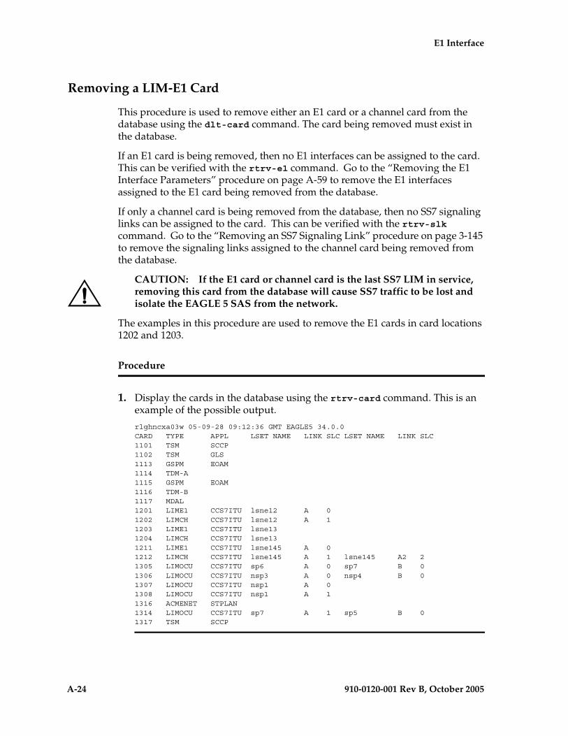
A-24 910-0120-001 Rev B, October 2005
E1 Interface
Removing a LIM-E1 Card
This procedure is used to remove either an E1 card or a channel card from the database using the dlt-card command. The card being removed must exist in the database.
If an E1 card is being removed, then no E1 interfaces can be assigned to the card. This can be verified with the rtrv-e1 command. Go to the “Removing the E1 Interface Parameters” procedure on page A-59 to remove the E1 interfaces assigned to the E1 card being removed from the database.
If only a channel card is being removed from the database, then no SS7 signaling links can be assigned to the card. This can be verified with the rtrv-slk command. Go to the “Removing an SS7 Signaling Link” procedure on page 3-145 to remove the signaling links assigned to the channel card being removed from the database.
CAUTION: If the E1 card or channel card is the last SS7 LIM in service, removing this card from the database will cause SS7 traffic to be lost and isolate the EAGLE 5 SAS from the network.
The examples in this procedure are used to remove the E1 cards in card locations 1202 and 1203.
Procedure
1. Display the cards in the database using the rtrv-card command. This is an example of the possible output.
rlghncxa03w 05-09-28 09:12:36 GMT EAGLE5 34.0.0CARD TYPE APPL LSET NAME LINK SLC LSET NAME LINK SLC1101 TSM SCCP 1102 TSM GLS 1113 GSPM EOAM1114 TDM-A1115 GSPM EOAM1116 TDM-B1117 MDAL1201 LIME1 CCS7ITU lsne12 A 0 1202 LIMCH CCS7ITU lsne12 A 1 1203 LIME1 CCS7ITU lsne13 1204 LIMCH CCS7ITU lsne13 1211 LIME1 CCS7ITU lsne145 A 0 1212 LIMCH CCS7ITU lsne145 A 1 lsne145 A2 21305 LIMOCU CCS7ITU sp6 A 0 sp7 B 01306 LIMOCU CCS7ITU nsp3 A 0 nsp4 B 01307 LIMOCU CCS7ITU nsp1 A 0 1308 LIMOCU CCS7ITU nsp1 A 1 1316 ACMENET STPLAN 1314 LIMOCU CCS7ITU sp7 A 1 sp5 B 01317 TSM SCCP
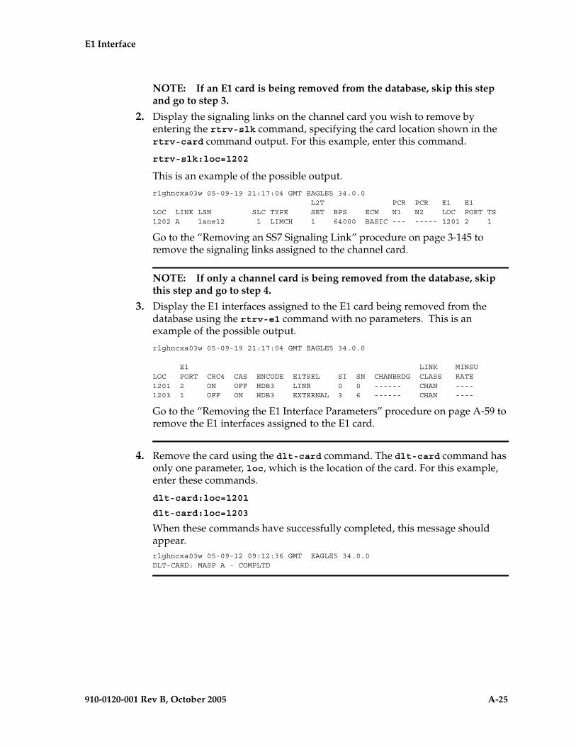
E1 Interface
910-0120-001 Rev B, October 2005 A-25
NOTE: If an E1 card is being removed from the database, skip this step and go to step 3.
2. Display the signaling links on the channel card you wish to remove by entering the rtrv-slk command, specifying the card location shown in the rtrv-card command output. For this example, enter this command.
rtrv-slk:loc=1202
This is an example of the possible output.
rlghncxa03w 05-09-19 21:17:04 GMT EAGLE5 34.0.0 L2T PCR PCR E1 E1LOC LINK LSN SLC TYPE SET BPS ECM N1 N2 LOC PORT TS1202 A lsne12 1 LIMCH 1 64000 BASIC --- ----- 1201 2 1
Go to the “Removing an SS7 Signaling Link” procedure on page 3-145 to remove the signaling links assigned to the channel card.
NOTE: If only a channel card is being removed from the database, skip this step and go to step 4.
3. Display the E1 interfaces assigned to the E1 card being removed from the database using the rtrv-e1 command with no parameters. This is an example of the possible output.
rlghncxa03w 05-09-19 21:17:04 GMT EAGLE5 34.0.0
E1 LINK MINSULOC PORT CRC4 CAS ENCODE E1TSEL SI SN CHANBRDG CLASS RATE1201 2 ON OFF HDB3 LINE 0 0 ------ CHAN ----1203 1 OFF ON HDB3 EXTERNAL 3 6 ------ CHAN ----
Go to the “Removing the E1 Interface Parameters” procedure on page A-59 to remove the E1 interfaces assigned to the E1 card.
4. Remove the card using the dlt-card command. The dlt-card command has only one parameter, loc, which is the location of the card. For this example, enter these commands.
dlt-card:loc=1201
dlt-card:loc=1203
When these commands have successfully completed, this message should appear.rlghncxa03w 05-09-12 09:12:36 GMT EAGLE5 34.0.0DLT-CARD: MASP A - COMPLTD
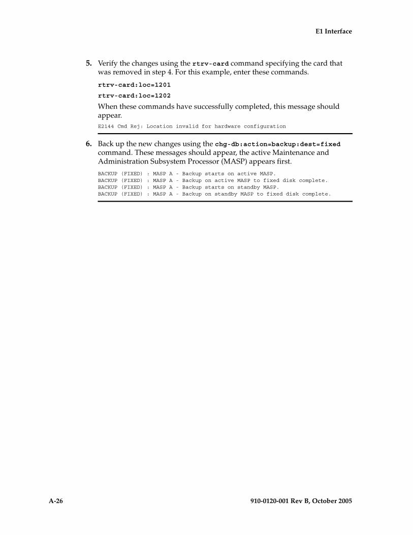
A-26 910-0120-001 Rev B, October 2005
E1 Interface
5. Verify the changes using the rtrv-card command specifying the card that was removed in step 4. For this example, enter these commands.
rtrv-card:loc=1201
rtrv-card:loc=1202
When these commands have successfully completed, this message should appear.E2144 Cmd Rej: Location invalid for hardware configuration
6. Back up the new changes using the chg-db:action=backup:dest=fixed command. These messages should appear, the active Maintenance and Administration Subsystem Processor (MASP) appears first.
BACKUP (FIXED) : MASP A - Backup starts on active MASP.BACKUP (FIXED) : MASP A - Backup on active MASP to fixed disk complete.BACKUP (FIXED) : MASP A - Backup starts on standby MASP.BACKUP (FIXED) : MASP A - Backup on standby MASP to fixed disk complete.

E1 Interface
910-0120-001 Rev B, October 2005 A-27
Flowchart A-2. Removing a LIM-E1 Card
Enter the rtrv-cardcommand
Enter thertrv-e1 command
Which card type isbeing removed from the
database?
Go to the "Removing an SS7 SignalingLink" procedure in Chapter 3, "SS7
Configuration," and remove the signalinglink assigned to the channel card
(LIMCH)
LIMCH Only
LIME1
Enter thertrv-e1 command with these parameters::loc=<card location of the LIME1 being
removed>:e1port=<e1port value assigned to the LIME1
being removed>
Go to the "Removing an E1 Interface"procedure and remove the signaling
links and timeslots serviced by the E1card being removed from the database
Enter thedlt-card:loc=<location of LIMCH
being removed> command
Enter thechg-db:action=backup:dest=fixed
command
Enter thertrv-card:loc=<location of the
LIME1 or LIMCH that wasremoved> command
Enter thedlt-card:loc=<location of LIME1
being removed> command
Enter thertrv-slk command with this parameter:
:loc=<card location of the LIMCH beingremoved>

A-28 910-0120-001 Rev B, October 2005
E1 Interface
Adding Channelized and non-Channel Bridged E1 Ports
The channelized and non-channel bridged E1 ports are provisioned in the database using the ent-e1 command using these parameters.
:loc – The location of the E1 card (card type lime1) that is servicing the E1 signaling link. The location of a channel card (card type limch) cannot be specified for this parameter.
:e1port – The E1 port on the E1 card used to service the E1 signaling link. The e1port value cannot already be assigned to the E1 card specified by the loc parameter.
:crc4 – Specifies whether or not CRC4 is enabled on the E1 signaling link. The default value is on (crc4=on).
:cas – Specifies whether CAS or CCS is used on the E1 signaling link. CAS is enabled with the cas=on parameter. CCS is enabled with the cas=off parameter. The default value is CCS enabled (cas=off). The cas=on parameter cannot be specified for an HC MIM.
:encode – Specifies the type of encoding or decoding that is used on the E1 signaling link, either HDB3 or AMI. The default value is HDB3 encoding (encode=hdb3). AMI encoding can be specified only for an E1/T1 MIM or for an HC MIM.
:e1tsel – The timing source for the E1 signaling link, master (external), slave (line), or recovered. The default value is slave timing (e1tsel=line).
The recovered timing source can be used only with the chanbrdg=on parameter and cannot be used in this procedure.
NOTE: To use an external high-speed master clock source other than RS-422, TDMs 870-0774-15 or later must be installed in card locations 1114 and 1116, and the TDM Global Timing Interface options must be configured. For more information, see the “Configuring the Options for the TDM Global Timing Interface” procedure on page 3-263.
:si – Specifies the value of the two spare international bits of NFAS data, from 0 to 3. The default value is 0 (si=0).
:sn – Specifies the value of the five spare national bits of NFAS data, from 0 to 31. The default value is 0 (sn=0).
The ent-e1 command contains other parameters that are not used in this procedure. These parameters and their usage are described in these sections:
• e1tsel=recovered, chanbrdg, and force=yes – “Adding Channel Bridged E1 Ports” procedure on page A-37.
• linkclass and minsurate – “Adding Unchannelized E1 Ports” procedure on page A-45.
The E1 card specified in this procedure must be in the database. This can be verified with the rtrv-card command.

E1 Interface
910-0120-001 Rev B, October 2005 A-29
If the cas=on parameter is specified with the ent-e1 command, timeslot 16 cannot be used when the E1 signaling link is provisioned with the ent-slk command in the “Adding an E1 Signaling Link” procedure on page A-77.
The E1 card cannot contain channelized and unchannelized E1 ports.
Procedure
1. Display the existing E1 interfaces in the database using the rtrv-e1 command with no parameters. This is an example of the possible output.
rlghncxa03w 05-09-19 21:17:04 GMT EAGLE5 34.0.0
E1 LINK MINSULOC PORT CRC4 CAS ENCODE E1TSEL SI SN CHANBRDG CLASS RATE1201 1 ON OFF HDB3 EXTERNAL 2 6 ------ CHAN ----1201 2 ON OFF HDB3 EXTERNAL 3 5 ------ CHAN ----1202 1 ON OFF HDB3 EXTERNAL 1 10 ------ CHAN ----1203 1 ON OFF HDB3 EXTERNAL 1 11 ------ CHAN ----1203 2 ON OFF HDB3 EXTERNAL 3 7 ------ CHAN ----1204 1 ON OFF HDB3 EXTERNAL 3 8 ------ CHAN ----1211 2 ON OFF HDB3 EXTERNAL 0 0 ------ CHAN ----1212 1 ON OFF HDB3 EXTERNAL 1 1 ------ CHAN ----1213 1 ON OFF HDB3 EXTERNAL 2 2 ------ CHAN ----1213 5 ON OFF HDB3 EXTERNAL 3 3 ------ CHAN ----
If the E1 card that the E1 port is being assigned to in this procedure is not shown in the rtrv-e1 output, or if the E1 card has unchannelized E1 ports assigned to it, go to step 2 to verify if there are any E1 cards in the database that have no E1 ports assigned to them.
If the rtrv-e1 output shows that the E1 card has channel bridged E1 ports assigned to it, or that E1 ports 3, 4, 5, 6, 7, or 8 are assigned to the E1 card, the E1 card is an HC MIM. Go to step 3 and add the E1 port with the parameters allowed for an HC MIM.
If the rtrv-e1 output shows that the E1 card does not have channel bridged E1 ports assigned to it, or that E1 ports 3, 4, 5, 6, 7, or 8 are not assigned to the E1 card, verify the type of E1 card that the E1 port will be assigned to. The E1 card types and their part numbers are shown in Table A-4 on page A-14. If the E1 card is an HC MIM, go to step 3 and add the E1 port with the parameters allowed for an HC MIM. If the E1 card is either a LIM-E1 card or an E1/T1 MIM, go to step 3 and add the E1 port with the parameters allowed for either a LIM-E1 card or an E1/T1 MIM.
If the E1 card you wish to use in this procedure has all the E1 ports that are allowed to be assigned to it, select another E1 card to add the E1 port to, or go to step 2 to verify if there are any E1 cards in the database that have no E1 ports assigned to them. Table A-7 shown the number of E1 ports that are allowed for the different E1 card types.
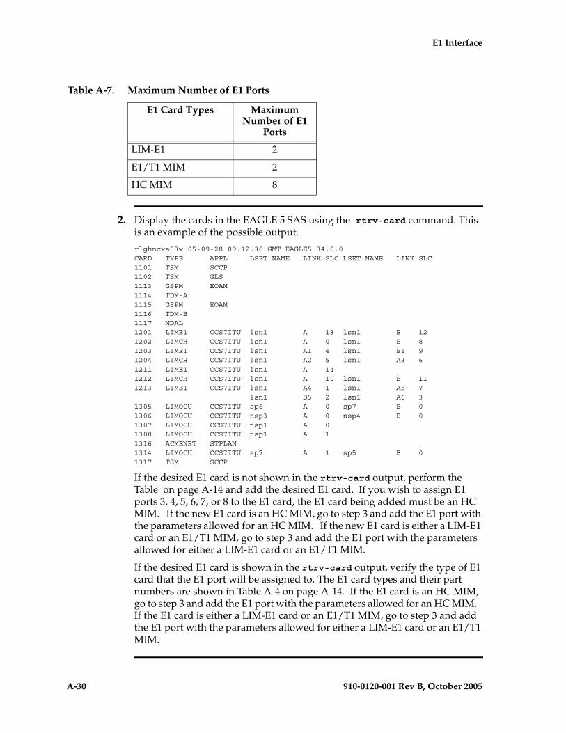
A-30 910-0120-001 Rev B, October 2005
E1 Interface
2. Display the cards in the EAGLE 5 SAS using the rtrv-card command. This is an example of the possible output.
rlghncxa03w 05-09-28 09:12:36 GMT EAGLE5 34.0.0CARD TYPE APPL LSET NAME LINK SLC LSET NAME LINK SLC1101 TSM SCCP 1102 TSM GLS 1113 GSPM EOAM1114 TDM-A1115 GSPM EOAM1116 TDM-B1117 MDAL1201 LIME1 CCS7ITU lsn1 A 13 lsn1 B 121202 LIMCH CCS7ITU lsn1 A 0 lsn1 B 81203 LIME1 CCS7ITU lsn1 A1 4 lsn1 B1 91204 LIMCH CCS7ITU lsn1 A2 5 lsn1 A3 61211 LIME1 CCS7ITU lsn1 A 141212 LIMCH CCS7ITU lsn1 A 10 lsn1 B 111213 LIME1 CCS7ITU lsn1 A4 1 lsn1 A5 7 lsn1 B5 2 lsn1 A6 31305 LIMOCU CCS7ITU sp6 A 0 sp7 B 01306 LIMOCU CCS7ITU nsp3 A 0 nsp4 B 01307 LIMOCU CCS7ITU nsp1 A 0 1308 LIMOCU CCS7ITU nsp1 A 1 1316 ACMENET STPLAN 1314 LIMOCU CCS7ITU sp7 A 1 sp5 B 01317 TSM SCCP
If the desired E1 card is not shown in the rtrv-card output, perform the Table on page A-14 and add the desired E1 card. If you wish to assign E1 ports 3, 4, 5, 6, 7, or 8 to the E1 card, the E1 card being added must be an HC MIM. If the new E1 card is an HC MIM, go to step 3 and add the E1 port with the parameters allowed for an HC MIM. If the new E1 card is either a LIM-E1 card or an E1/T1 MIM, go to step 3 and add the E1 port with the parameters allowed for either a LIM-E1 card or an E1/T1 MIM.
If the desired E1 card is shown in the rtrv-card output, verify the type of E1 card that the E1 port will be assigned to. The E1 card types and their part numbers are shown in Table A-4 on page A-14. If the E1 card is an HC MIM, go to step 3 and add the E1 port with the parameters allowed for an HC MIM. If the E1 card is either a LIM-E1 card or an E1/T1 MIM, go to step 3 and add the E1 port with the parameters allowed for either a LIM-E1 card or an E1/T1 MIM.
Table A-7. Maximum Number of E1 Ports
E1 Card Types Maximum Number of E1
Ports
LIM-E1 2
E1/T1 MIM 2
HC MIM 8

E1 Interface
910-0120-001 Rev B, October 2005 A-31
3. Add the new E1 interface information to the database using the ent-e1 command and the parameter combinations shown in Table A-8, based on the type of E1 card being used.
For this example, enter these commands.
ent-e1:loc=1203:e1port=2:encode=hdb3:e1tsel=line:si=1:sn=7
ent-e1:loc=1211:e1port=2:crc4=on:encode=hdb3:e1tsel=line
When each of these commands have successfully completed, this message should appear.
rlghncxa03w 05-09-12 09:12:36 GMT EAGLE5 34.0.0ENT-E1: MASP A - COMPLTD
Table A-8. E1 Interface Parameter Combinations
LIM-E1 Card E1/T1 MIM HC MIM without Channel Bridging
Mandatory Parameters
:loc=location of the E1 card :loc=location of the E1 card :loc=location of the E1 card
:e1port=1, 2 :e1port=1, 2 :e1port=1, 2, 3, 4, 5, 6, 7, 8
Optional Parameters
:cas=on, offDefault value = off
:cas=on, offDefault value = off
:cas=offDefault value = off
:crc4=on, offDefault value = on
:crc4=on, offDefault value = on
:crc4=on, offDefault value = on
:encode=hdb3Default value = hdb3
:encode=ami, hdb3Default value = hdb3
:encode=ami, hdb3Default value = hdb3
:si=0 - 3Default value = 0
:si=0 - 3Default value = 0
:si=0 - 3Default value = 0
:sn=0 - 31Default value = 0
:sn=0 - 31Default value = 0
:sn=0 - 31Default value = 0
:e1tsel=line, externalDefault value = line
:e1tsel=line, external Default value = line
:e1tsel=line, external Default value = line
Notes:1. Channel cards cannot be specified with the ent-e1 command.2. To configure the E1 port for master timing, use the e1tsel=external parameter.3. The linkclass=chan parameter configures a channelized E1 port. Specifying the linkclass=chan parameter in this procedure is unneccessary as this is the default value for the linkclass parameter.

A-32 910-0120-001 Rev B, October 2005
E1 Interface
4. Verify the changes using the rtrv-e1 command specifying the card location and the e1port value specified in step 3. For this example, enter these commands.
rtrv-e1:loc=1203:e1port=2
This is an example of the possible output.
rlghncxa03w 05-09-28 09:12:36 GMT EAGLE5 34.0.0
E1 LINK MINSULOC PORT CRC4 CAS ENCODE E1TSEL SI SN CHANBRDG CLASS RATE1203 2 OFF OFF HDB3 LINE 1 7 ------ CHAN ----
TS0 (N/A) TS8 ------ TS16 ------ TS24 ------TS1 ------ TS9 ------ TS17 ------ TS25 ------TS2 ------ TS10 ------ TS18 ------ TS26 ------TS3 ------ TS11 ------ TS19 ------ TS27 ------TS4 ------ TS12 ------ TS20 ------ TS28 ------TS5 ------ TS13 ------ TS21 ------ TS29 ------TS6 ------ TS14 ------ TS22 ------ TS30 ------TS7 ------ TS15 ------ TS23 ------ TS31 ------
rtrv-e1:loc=1211:e1port=2
This is an example of the possible output.
rlghncxa03w 05-09-28 09:12:36 GMT EAGLE5 34.0.0
E1 LINK MINSULOC PORT CRC4 CAS ENCODE E1TSEL SI SN CHANBRDG CLASS RATE1211 2 ON OFF HDB3 LINE 0 0 ------ CHAN ----
TS0 (N/A) TS8 ------ TS16 ------ TS24 ------TS1 ------ TS9 ------ TS17 ------ TS25 ------TS2 ------ TS10 ------ TS18 ------ TS26 ------TS3 ------ TS11 ------ TS19 ------ TS27 ------TS4 ------ TS12 ------ TS20 ------ TS28 ------TS5 ------ TS13 ------ TS21 ------ TS29 ------TS6 ------ TS14 ------ TS22 ------ TS30 ------TS7 ------ TS15 ------ TS23 ------ TS31 ------
5. Backup the new changes using the chg-db:action=backup:dest=fixed command. These messages should appear, the active Maintenance and Administration Subsystem Processor (MASP) appears first.
BACKUP (FIXED) : MASP A - Backup starts on active MASP.BACKUP (FIXED) : MASP A - Backup on active MASP to fixed disk complete.BACKUP (FIXED) : MASP A - Backup starts on standby MASP.BACKUP (FIXED) : MASP A - Backup on standby MASP to fixed disk complete.

E1 Interface
910-0120-001 Rev B, October 2005 A-33
Flowchart A-3. Adding Channelized and non-Channel Bridged E1 Ports (Sheet 1 of 4)

A-34 910-0120-001 Rev B, October 2005
E1 Interface
Flowchart A-3. Adding Channelized and non-Channel Bridged E1 Ports (Sheet 2 of 4)

E1 Interface
910-0120-001 Rev B, October 2005 A-35
Flowchart A-3. Adding Channelized and non-Channel Bridged E1 Ports (Sheet 3 of 4)
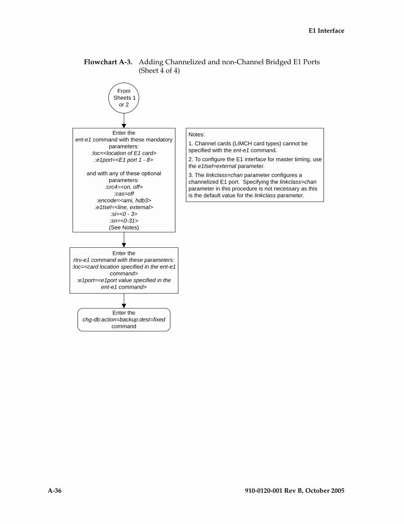
A-36 910-0120-001 Rev B, October 2005
E1 Interface
Flowchart A-3. Adding Channelized and non-Channel Bridged E1 Ports (Sheet 4 of 4)

E1 Interface
910-0120-001 Rev B, October 2005 A-37
Adding Channel Bridged E1 Ports
The channel bridged E1 ports are provisioned in the database using the ent-e1 command using these parameters.
:loc – The location of the E1 card (card type lime1) that is servicing the E1 signaling link. The E1 card must be an HC MIM. The location of a channel card (card type limch) cannot be specified for this parameter.
:e1port – The E1 port on the E1 card used to service the E1 signaling link. The e1port value cannot already be assigned to the E1 card specified by the loc parameter.
:crc4 – Specifies whether or not CRC4 is enabled on the E1 signaling link. The default value is on (crc4=on).
:cas – Specifies whether CAS or CCS is used on the E1 signaling link. CAS is enabled with the cas=on parameter. CCS is enabled with the cas=off parameter. The default value is CCS enabled (cas=off). The cas=on parameter cannot be specified for an HC MIM.
:encode – Specifies the type of encoding or decoding that is used on the E1 signaling link, either HDB3 or AMI. The default value is HDB3 encoding (encode=hdb3).
:e1tsel – The timing source for the E1 signaling link, master (external) or recovered. The default value is slave timing (e1tsel=line) which cannot be used for a channel bridged E1 port.
The recovered timing source can be used only with the chanbrdg=on parameter and uses the even numbered member of the bridged-pair as a clock source, ensuring that port in the pair can recover the timing from its partner.
NOTE: To use an external high-speed master clock source other than RS-422, TDMs 870-0774-15 or later must be installed in card locations 1114 and 1116, and the TDM Global Timing Interface options must be configured. For more information, see the “Configuring the Options for the TDM Global Timing Interface” procedure on page 3-263.
:si – Specifies the value of the two spare international bits of NFAS data, from 0 to 3. The default value is 0 (si=0).
:sn – Specifies the value of the five spare national bits of NFAS data, from 0 to 31. The default value is 0 (sn=0).
:chanbrdg – Specifies whether or not the odd numbered E1 port specified in this procedure is channel bridged to its adjacent even numbered E1 port. Table A-9 on page A-38 shows the E1 ports that can be specified with the chanbrdg=on parameter and the even-numbered E1 ports that are bridged to the odd numbered E1 port.

A-38 910-0120-001 Rev B, October 2005
E1 Interface
:force=yes – Required when the even numbered E1 port being channel bridged is provisioned in the database before this procedure is performed.
The ent-e1 command contains the linkclass and minsurate parameters that are not used in this procedure. These parameters and their usage are described in the “Adding Unchannelized E1 Ports” procedure on page A-45.
The E1 card specified in this procedure must be in the database. This can be verified with the rtrv-card command.
The E1 card cannot contain channelized and un-channelized E1 ports.
Procedure
1. Display the cards in the EAGLE 5 SAS using the rtrv-card command. This is an example of the possible output.
rlghncxa03w 05-09-28 09:12:36 GMT EAGLE5 34.0.0CARD TYPE APPL LSET NAME LINK SLC LSET NAME LINK SLC1101 TSM SCCP 1102 TSM GLS 1113 GSPM EOAM1114 TDM-A1115 GSPM EOAM1116 TDM-B1117 MDAL1201 LIME1 CCS7ITU lsn1 A 13 lsn1 B 121202 LIMCH CCS7ITU lsn1 A 0 lsn1 B 81203 LIME1 CCS7ITU lsn1 A1 4 lsn1 B1 91204 LIMCH CCS7ITU lsn1 A2 5 lsn1 A3 61211 LIME1 CCS7ITU lsn1 A 141212 LIMCH CCS7ITU lsn1 A 10 lsn1 B 111213 LIME1 CCS7ITU lsn1 A4 1 lsn1 A5 7 lsn1 B5 2 lsn1 A6 31305 LIMOCU CCS7ITU sp6 A 0 sp7 B 01306 LIMOCU CCS7ITU nsp3 A 0 nsp4 B 01307 LIMOCU CCS7ITU nsp1 A 0 1308 LIMOCU CCS7ITU nsp1 A 1 1316 ACMENET STPLAN 1314 LIMOCU CCS7ITU sp7 A 1 sp5 B 01317 TSM SCCP
If there no LIME1 cards shown in the rtrv-card output, perform the “Adding a LIM-E1 Card” procedure on page A-14 and add an HC MIM to the database. Skip step 2 and go to step 3.
Table A-9. Channel Bridging Ports
Odd Numbered E1 Port
Even Numbered Bridged E1 Port
1 2
3 4
5 6
7 8

E1 Interface
910-0120-001 Rev B, October 2005 A-39
2. Display the existing E1 interfaces in the database using the rtrv-e1 command with no parameters. This is an example of the possible output.
rlghncxa03w 05-09-19 21:17:04 GMT EAGLE5 34.0.0
E1 LINK MINSULOC PORT CRC4 CAS ENCODE E1TSEL SI SN CHANBRDG CLASS RATE1201 1 ON OFF HDB3 EXTERNAL 2 6 ------ CHAN ----1201 2 ON OFF HDB3 EXTERNAL 3 5 ------ CHAN ----1202 1 ON OFF HDB3 EXTERNAL 1 10 ------ CHAN ----1203 1 ON OFF HDB3 EXTERNAL 1 11 ------ CHAN ----1203 2 ON OFF HDB3 EXTERNAL 3 7 ------ CHAN ----1204 1 ON OFF HDB3 EXTERNAL 3 8 ------ CHAN ----1211 2 ON OFF HDB3 EXTERNAL 0 0 ------ CHAN ----1212 1 ON OFF HDB3 EXTERNAL 1 1 ------ CHAN ----1213 1 ON OFF HDB3 EXTERNAL 2 2 ------ CHAN ----1213 5 ON OFF HDB3 EXTERNAL 3 3 ------ CHAN ----
Channel bridged E1 ports cannot be added to an E1 card containing unchannelized E1 ports. If the E1 card contains unchannelized E1 ports, choose another E1 card from step 1 and repeat step 2, or add a new HC MIM by performing the “Adding a LIM-E1 Card” procedure on page A-14.
If the rtrv-e1 output shows that the E1 card has E1 ports 3, 4, 5, 6, 7, or 8 assigned to it, or that E1 ports on the E1 card are channel bridged, skip this step and go to step 3.
If the rtrv-e1 output shows that the E1 card does not have E1 ports 3, 4, 5, 6, 7, or 8 assigned to it, or that E1 ports on the E1 card are not channel bridged, verify that the E1 card that the channel bridged E1 port will be assigned to is an HC MIM. The part number of the HC MIM is 870-2671-01. If the E1 card is not an HC MIM, add a new HC MIM by performing the “Adding a LIM-E1 Card” procedure on page A-14.

A-40 910-0120-001 Rev B, October 2005
E1 Interface
NOTE: If a new HC MIM was added in step 2, skip step 3, and go to 4.
3. Display the E1 signaling links in the EAGLE 5 SAS by entering this command.
rtrv-slk:class=e1
This is an example of the possible output.
rlghncxa03w 05-09-19 21:17:04 GMT EAGLE5 34.0.0
L2T PCR PCR E1 E1LOC LINK LSN SLC TYPE SET BPS ECM N1 N2 LOC PORT TS1201 A lsn1 13 LIME1 1 56000 BASIC --- ----- 1201 2 251201 B lsn1 12 LIME1 1 56000 BASIC --- ----- 1201 1 201202 A lsn1 0 LIMCH 1 56000 BASIC --- ----- 1201 1 51202 B lsn1 8 LIMCH 1 56000 BASIC --- ----- 1201 1 11203 A1 lsn1 4 LIME1 1 56000 BASIC --- ----- 1203 2 201203 B1 lsn1 9 LIME1 1 56000 BASIC --- ----- 1203 1 21204 A2 lsn1 5 LIMCH 1 56000 BASIC --- ----- 1203 1 211204 A3 lsn1 6 LIMCH 1 56000 BASIC --- ----- 1203 1 221211 A lsn1 14 LIME1 1 56000 BASIC --- ----- 1211 1 71212 A lsn1 10 LIMCH 1 56000 BASIC --- ----- 1211 1 281212 B lsn1 11 LIMCH 1 56000 BASIC --- ----- 1211 1 251213 A4 lsn1 1 LIME1 1 56000 BASIC --- ----- 1213 1 171213 A5 lsn1 7 LIME1 1 56000 BASIC --- ----- 1213 5 231213 B5 lsn1 2 LIME1 1 56000 BASIC --- ----- 1213 1 241213 A6 lsn1 3 LIME1 1 56000 BASIC --- ----- 1213 5 19
If an even numbered E1 port is to be channel bridged, and that E1 port is assigned to signaling links, these signaling links must be removed before the E1 port can be channel bridged. Perform the “Removing an SS7 Signaling Link” procedure on page 3-145 and remove these signaling links. After the signaling links have been removed, go to step 4.
If the even numbered E1 port to be channel bridged is not assigned to signaling links, go to step 4.

E1 Interface
910-0120-001 Rev B, October 2005 A-41
4. Add the new E1 interface information to the database using the ent-e1 command and the parameter combinations shown in Table A-10.
For this example, enter these commands.
ent-e1:loc=1301:e1port=1:encode=hdb3:e1tsel=external:si=1:sn=7:chanbrdg=on
ent-e1:loc=1303:e1port=1:crc4=on:encode=hdb3:e1tsel=recovered:chanbrdg=on
When each of these commands have successfully completed, this message should appear.
rlghncxa03w 05-09-12 09:12:36 GMT EAGLE5 34.0.0ENT-E1: MASP A - COMPLTD
Table A-10. Channel Bridged E1 Port Combinations
Mandatory Parameters
:loc=location of the E1 card :e1tsel=external, recovered
:e1port=1, 3, 5, 7 :chanbrdg=on
Optional Parameters
:cas=offDefault value = off
:si=0 - 3Default value = 0
:crc4=on, off Default value = on
:sn=0 - 31Default value = 0
:encode=ami, hdb3Default value = hdb3
:force=yes
Notes:1. Channel cards cannot be specified with the ent-e1 command.2. To configure the E1 port for master timing, use the e1tsel=external parameter.3. The linkclass=chan parameter configures a channelized E1 port. Specifying the linkclass=chan parameter in this procedure is unneccessary as this is the default value for the linkclass parameter.4. The E1 card cannot contain channelized and un-channelized E1 ports.5. The force=yes parameter must be used when the even numbered port being channel bridged is shown in the rtrv-e1 output in step 2. If the even numbered port being channel bridged is not shown in the rtrv-e1 output in step 2, the force=yes parameter cannot be used.

A-42 910-0120-001 Rev B, October 2005
E1 Interface
5. Verify the changes using the rtrv-e1 command specifying the card location and the e1port value specified in step 5. For this example, enter these commands.
rtrv-e1:loc=1301:e1port=1
This is an example of the possible output.
rlghncxa03w 05-09-28 09:12:36 GMT EAGLE5 34.0.0
E1 LINK MINSULOC PORT CRC4 CAS ENCODE E1TSEL SI SN CHANBRDG CLASS RATE1301 1 OFF OFF HDB3 EXTERNAL 1 7 MASTER CHAN ----
TS0 (N/A) TS8 ------ TS16 ------ TS24 ------TS1 ------ TS9 ------ TS17 ------ TS25 ------TS2 ------ TS10 ------ TS18 ------ TS26 ------TS3 ------ TS11 ------ TS19 ------ TS27 ------TS4 ------ TS12 ------ TS20 ------ TS28 ------TS5 ------ TS13 ------ TS21 ------ TS29 ------TS6 ------ TS14 ------ TS22 ------ TS30 ------TS7 ------ TS15 ------ TS23 ------ TS31 ------
rtrv-e1:loc=1303:e1port=1
This is an example of the possible output.
rlghncxa03w 05-09-28 09:12:36 GMT EAGLE5 34.0.0
E1 LINK MINSULOC PORT CRC4 CAS ENCODE E1TSEL SI SN CHANBRDG CLASS RATE1303 1 ON OFF HDB3 RECOVERED 0 0 MASTER CHAN ----
TS0 (N/A) TS8 ------ TS16 ------ TS24 ------TS1 ------ TS9 ------ TS17 ------ TS25 ------TS2 ------ TS10 ------ TS18 ------ TS26 ------TS3 ------ TS11 ------ TS19 ------ TS27 ------TS4 ------ TS12 ------ TS20 ------ TS28 ------TS5 ------ TS13 ------ TS21 ------ TS29 ------TS6 ------ TS14 ------ TS22 ------ TS30 ------TS7 ------ TS15 ------ TS23 ------ TS31 ------
6. Backup the new changes using the chg-db:action=backup:dest=fixed command. These messages should appear, the active Maintenance and Administration Subsystem Processor (MASP) appears first.
BACKUP (FIXED) : MASP A - Backup starts on active MASP.BACKUP (FIXED) : MASP A - Backup on active MASP to fixed disk complete.BACKUP (FIXED) : MASP A - Backup starts on standby MASP.BACKUP (FIXED) : MASP A - Backup on standby MASP to fixed disk complete.

E1 Interface
910-0120-001 Rev B, October 2005 A-43
Flowchart A-3. Adding Channel Bridged E1 Ports (Sheet 1 of 2)

A-44 910-0120-001 Rev B, October 2005
E1 Interface
Flowchart A-3. Adding Channel Bridged E1 Ports (Sheet 2 of 2)

E1 Interface
910-0120-001 Rev B, October 2005 A-45
Adding Unchannelized E1 Ports
The E1 interface parameters are provisioned in the database using the ent-e1 command using these parameters.
:loc – The location of the E1 card (card type lime1) that is servicing the E1 signaling link. The E1 card must be an HC MIM card. The location of a channel card (card type limch) cannot be specified for this parameter.
:e1port – The E1 port on the E1 card used to service the E1 signaling link. The e1port value cannot already be assigned to the E1 card specified by the loc parameter.
:crc4 – Specifies whether or not CRC4 is enabled on the E1 signaling link. The default value is on (crc4=on).
:cas – Specifies whether CAS or CCS is used on the E1 signaling link. CAS is enabled with the cas=on parameter. CCS is enabled with the cas=off parameter. The default value is CCS enabled (cas=off). The cas=on parameter cannot be specified for an HC MIM.
:encode – Specifies the type of encoding or decoding that is used on the E1 signaling link, either HDB3 or AMI. The default value is HDB3 encoding (encode=hdb3).
:e1tsel – The timing source for the E1 signaling link, master (external) or slave (line). The default value is slave timing (e1tsel=line).
NOTE: To use an external high-speed master clock source other than RS-422, TDMs 870-0774-15 or later must be installed in card locations 1114 and 1116, and the TDM Global Timing Interface options must be configured. For more information, see the “Configuring the Options for the TDM Global Timing Interface” procedure on page 3-263.
:si – Specifies the value of the two spare international bits of NFAS data, from 0 to 3. The default value is 0 (si=0).
:sn – Specifies the value of the five spare national bits of NFAS data, from 0 to 31. The default value is 0 (sn=0).
:linkclass – Indicates whether the E1 port supports channelized (linkclass=chan) or un-channelized (linkclass=unchan) E1 signaling links.
:minsurate – Specifies the minimum number of signaling units (FISUs and LSSUs) per second that are transmitted on the outbound E1 signaling link during idle periods or when there is an unused portion of the link’s bandwidth. The value of this parameter is from 500 to 2000 signaling units per second, with the default value of 1000 signaling units per second. The minsurate parameter can be specified only when an unchannelized E1 port (linkclass=unchan parameter) is being configured.

A-46 910-0120-001 Rev B, October 2005
E1 Interface
The ent-e1 command contains the e1tsel=recovered, chanbrdg, and force=yes parameters. These parameters are not used in this procedure. These parameters and their usage are described in the “Adding Channel Bridged E1 Ports” procedure on page A-37.
The E1 card specified in this procedure must be in the database. This can be verified with the rtrv-card command.
Procedure
1. Display the cards in the EAGLE 5 SAS using the rtrv-card command. This is an example of the possible output.
rlghncxa03w 05-09-28 09:12:36 GMT EAGLE5 34.0.0CARD TYPE APPL LSET NAME LINK SLC LSET NAME LINK SLC1101 TSM SCCP 1102 TSM GLS 1113 GSPM EOAM1114 TDM-A1115 GSPM EOAM1116 TDM-B1117 MDAL1201 LIME1 CCS7ITU lsn1 A 13 lsn1 B 121202 LIMCH CCS7ITU lsn1 A 0 lsn1 B 81203 LIME1 CCS7ITU lsn1 A1 4 lsn1 B1 91204 LIMCH CCS7ITU lsn1 A2 5 lsn1 A3 61211 LIME1 CCS7ITU lsn1 A 141212 LIMCH CCS7ITU lsn1 A 10 lsn1 B 111213 LIME1 CCS7ITU lsn1 A4 1 lsn1 A5 7 lsn1 B5 2 lsn1 A6 31305 LIMOCU CCS7ITU sp6 A 0 sp7 B 01306 LIMOCU CCS7ITU nsp3 A 0 nsp4 B 01307 LIMOCU CCS7ITU nsp1 A 0 1308 LIMOCU CCS7ITU nsp1 A 1 1316 ACMENET STPLAN 1314 LIMOCU CCS7ITU sp7 A 1 sp5 B 01317 TSM SCCP
If there no LIME1 cards shown in the rtrv-card output, perform the “Adding a LIM-E1 Card” procedure on page A-14 and add an HC MIM to the database. Skip step 2 and go to step 3.

E1 Interface
910-0120-001 Rev B, October 2005 A-47
2. Display the existing E1 interfaces in the database using the rtrv-e1 command with no parameters. This is an example of the possible output.
rlghncxa03w 05-09-19 21:17:04 GMT EAGLE5 34.0.0
E1 LINK MINSULOC PORT CRC4 CAS ENCODE E1TSEL SI SN CHANBRDG CLASS RATE1201 1 ON OFF HDB3 EXTERNAL 2 6 ------ CHAN ----1201 2 ON OFF HDB3 EXTERNAL 3 5 ------ CHAN ----1202 1 ON OFF HDB3 EXTERNAL 1 10 ------ CHAN ----1203 1 ON OFF HDB3 EXTERNAL 1 11 ------ CHAN ----1203 2 ON OFF HDB3 EXTERNAL 3 7 ------ CHAN ----1204 1 ON OFF HDB3 EXTERNAL 3 8 ------ CHAN ----1211 2 ON OFF HDB3 EXTERNAL 0 0 ------ CHAN ----1212 1 ON OFF HDB3 EXTERNAL 1 1 ------ CHAN ----1213 1 ON OFF HDB3 EXTERNAL 2 2 ------ CHAN ----1213 5 ON OFF HDB3 EXTERNAL 3 3 ------ CHAN ----
The EAGLE 5 SAS can contain a maximum of 64 unchannelized E1 ports. If the rtrv-e1 output shows that there are 64 unchannelized E1 ports, no other unchannelized E1 ports can be added and this procedure cannot be performed.
If no E1 ports are assigned to the E1 card you wish to use in this procedure, verify that the E1 card is an HC MIM. The part number of the HC MIM is 870-2671-01. If the E1 card is not an HC MIM, either select another E1 card from the rtrv-e1 output, or add a new HC MIM by performing the “Adding a LIM-E1 Card” procedure on page A-14.
If the E1 card is an HC MIM, go to step 3.
If E1 ports are assigned to the E1 card you wish to use in this procedure, and the E1 ports on the E1 card are channelized, unchannelized E1 ports cannot be assigned to this E1 card. Unchannelized E1 ports cannot be assigned to an E1 card that contains channelized E1 ports. If the E1 ports on the E1 card are channelized, either select another E1 card from the rtrv-e1 output, or add a new HC MIM by performing the “Adding a LIM-E1 Card” procedure on page A-14. If all the E1 ports shown in the rtrv-e1 output are channelized, add a new HC MIM by performing the “Adding a LIM-E1 Card” procedure on page A-14.
If any the E1 ports shown in the rtrv-e1 output are not channelized, either select another E1 card from the rtrv-e1 output that contains only one unchannelized E1 port, or add a new HC MIM by performing the “Adding a LIM-E1 Card” procedure on page A-14. The E1 card can contain a maximum of two unchannelized E1 ports. If the E1 card you wish to use in this procedure contains only one unchannelized E1 port, go to step 3.

A-48 910-0120-001 Rev B, October 2005
E1 Interface
3. Display the status of the SE-HSL SLK Capacity feature by entering the rtrv-ctrl-feat command. The following is an example of the possible output.
rlghncxa03w 05-09-28 21:15:37 GMT EAGLE5 34.0.0The following features have been permanently enabled:
Feature Name Partnum Status QuantityIPGWx Signaling TPS 893012814 on 20000ISUP Normalization 893000201 on ----Command Class Management 893005801 on ----LNP Short Message Service 893006601 on ----Intermed GTT Load Sharing 893006901 on ----XGTT Table Expansion 893006101 on 400000XMAP Table Expansion 893007701 on 3000HC-MIM SLK Capacity 893012707 on 64
The following features have been temporarily enabled:
Feature Name Partnum Status Quantity Trial Period LeftZero entries found.
The following features have expired temporary keys:
Feature Name PartnumZero entries found.
If the SE-HSL SLK Capacity feature is enabled, the entry SE-HSL SLK Capacity is shown in the rtrv-ctrl-feat output with a quantity of 4, 8, 16, 24, 32, 40, 48, 56 or 64. This quantity is the number of unchannelized E1 signaling links, and the number of unchannelized E1 ports, the EAGLE 5 SAS can contain. If the addition of the unchannelized E1 port in this procedure will not exceed the enabled unchannelized E1 signaling link quantity, go to step 10. If the addition of the unchannelized E1 port in this procedure will exceed the enabled unchannelized E1 signaling link quantity, increase the enabled unchannelized E1 signaling link quantity by performing step 8.
If the SE-HSL SLK Capacity feature is not enabled, go to step 4.
NOTE: If the rtrv-ctrl-feat output in step 3 shows any controlled features, skip steps 4 through 7, and go to step 8. If the rtrv-ctrl-feat output shows only the IPGWx Signaling TPS feature with a quantity of 200 and the HC-MIM SLK Capacity feature with a quantity of 64, steps 4 through 7 must be performed.
4. Display the serial number in the database with the rtrv-serial-num command. This is an example of the possible output.rlghncxa03w 05-09-28 21:15:37 GMT EAGLE5 34.0.0System serial number = nt00001231
System serial number is not locked.
rlghncxa03w 05-09-28 21:15:37 GMT EAGLE5 34.0.0Command Completed

E1 Interface
910-0120-001 Rev B, October 2005 A-49
NOTE: If the serial number is correct and locked, skip steps 5, 6, and 7, and go to step 8. If the serial number is correct but not locked, skip steps 5 and 6, and go to step 7. If the serial number is not correct, but is locked, the unchannelized E1 signaling link (SE-HSL SLK Capacity feature) quantity cannot be enabled and the remainder of this procedure cannot be performed. Contact the Customer Care Center to get an incorrect and locked serial number changed. Refer to “Customer Care Center” on page 1-8 for the contact information. The serial number can be found on a label affixed to the control shelf (shelf 1100).
5. Enter the correct serial number into the database using the ent-serial-num command with the serial parameter. For this example, enter this command.ent-serial-num:serial=<EAGLE 5 SAS’s correct serial number>
When this command has successfully completed, the following message should appear.rlghncxa03w 05-09-28 21:15:37 GMT EAGLE5 34.0.0ENT-SERIAL-NUM: MASP A - COMPLTD
6. Verify that the serial number entered in step 5 was entered correctly using the rtrv-serial-num command. This is an example of the possible output.
rlghncxa03w 05-09-28 21:15:37 GMT EAGLE5 34.0.0System serial number = nt00001231
System serial number is not locked.
rlghncxa03w 05-09-28 21:15:37 GMT EAGLE5 34.0.0Command Completed
If the serial number was not entered correctly, repeat steps 4 and 5 and re-enter the correct serial number.
7. Lock the serial number in the database by entering the ent-serial-num command with the serial number shown in step 4, if the serial number shown in step 4 is correct, or with the serial number shown in step 6, if the serial number was changed in step 5, and with the lock=yes parameter.
For this example, enter this command.ent-serial-num:serial=<EAGLE 5 SAS’s serial number>:lock=yes
When this command has successfully completed, the following message should appear.rlghncxa03w 05-09-28 21:15:37 GMT EAGLE5 34.0.0ENT-SERIAL-NUM: MASP A - COMPLTD

A-50 910-0120-001 Rev B, October 2005
E1 Interface
8. Enable the SE-HSL SLK Capacity feature by entering the enable-ctrl-feat command specifying the part number for the desired unchannelized E1 signaling link quantity and the feature access key. The unchannelized E1 signaling link quantity part numbers are shown in Table A-11.
For this example, enter this command.
enable-ctrl-feat:partnum=893013001:fak=<feature access key>
NOTE: A temporary feature access key cannot be specified to enable the unchannelized E1 signaling link quantity.
NOTE: The value for the feature access key (the fak parameter) is provided by Tekelec. If you do not have the feature access key for the unchannelized E1 signaling link quantity, contact your Tekelec Sales Representative or Account Representative.
When the enable-ctrl-feat command has successfully completed, this message should appear.
rlghncxa03w 05-09-28 21:15:37 GMT EAGLE5 34.0.0ENABLE-CTRL-FEAT: MASP B - COMPLTD
Table A-11. Unchannelized E1 Signaling Link Quantity Part Numbers
Unchannelized E1 Signaling
Link Quantity
Part Number
4 893013001
8 893013002
16 893013003
24 893013004
32 893013005
40 893013006
48 893013007
56 893013008
64 893013009

E1 Interface
910-0120-001 Rev B, October 2005 A-51
9. Verify the changes by entering the rtrv-ctrl-feat command with the unchannelized E1 signaling link quantity (SE-HSL SLK Capacity feature) part number specified in step 8. Enter this command.
rtrv-ctrl-feat:partnum=893013001
The following is an example of the possible output.rlghncxa03w 05-09-28 21:15:37 GMT EAGLE5 34.0.0The following features have been permanently enabled:
Feature Name Partnum Status QuantitySE-HSL SLK Capacity 893013001 on 4
The following features have been temporarily enabled:
Feature Name Partnum Status Quantity Trial Period LeftZero entries found.
The following features have expired temporary keys:
Feature Name PartnumZero entries found.
10. Add the unchannelized E1 port to the database using the ent-e1 command and the parameter combinations shown in Table A-12.
For this example, enter these commands.ent-e1:loc=1305:e1port=2:encode=hdb3:e1tsel=line:si=1:sn=7:linkclass=unchan
ent-e1:loc=1307:e1port=2:crc4=on:encode=hdb3:e1tsel=external:linkclass=unchan
When each of these commands have successfully completed, this message should appear.rlghncxa03w 05-09-12 09:12:36 GMT EAGLE5 34.0.0ENT-E1: MASP A - COMPLTD
Table A-12. Unchannelized E1 Port Parameter Combinations
Mandatory Parameters
:loc=card location of the HC MIM :linkclass=unchan
:e1port=1, 2, 3, 4, 5, 6, 7, 8 :e1tsel=line, external
Optional Parameters
:cas=offDefault value = off
:si=0 - 3Default value = 0
:crc4=on, offDefault value = on
:sn=0 - 31Default value = 0
:encode=ami, hdb3Default value = hdb3
:minsurate=500 - 2000Default value = 1000
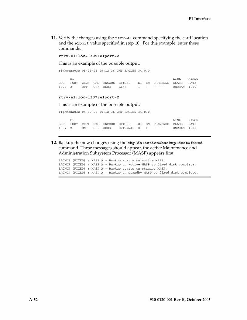
A-52 910-0120-001 Rev B, October 2005
E1 Interface
11. Verify the changes using the rtrv-e1 command specifying the card location and the e1port value specified in step 10. For this example, enter these commands.
rtrv-e1:loc=1305:e1port=2
This is an example of the possible output.
rlghncxa03w 05-09-28 09:12:36 GMT EAGLE5 34.0.0
E1 LINK MINSULOC PORT CRC4 CAS ENCODE E1TSEL SI SN CHANBRDG CLASS RATE1305 2 OFF OFF HDB3 LINE 1 7 ------ UNCHAN 1000
rtrv-e1:loc=1307:e1port=2
This is an example of the possible output.
rlghncxa03w 05-09-28 09:12:36 GMT EAGLE5 34.0.0
E1 LINK MINSULOC PORT CRC4 CAS ENCODE E1TSEL SI SN CHANBRDG CLASS RATE1307 2 ON OFF HDB3 EXTERNAL 0 0 ------ UNCHAN 1000
12. Backup the new changes using the chg-db:action=backup:dest=fixed command. These messages should appear, the active Maintenance and Administration Subsystem Processor (MASP) appears first.
BACKUP (FIXED) : MASP A - Backup starts on active MASP.BACKUP (FIXED) : MASP A - Backup on active MASP to fixed disk complete.BACKUP (FIXED) : MASP A - Backup starts on standby MASP.BACKUP (FIXED) : MASP A - Backup on standby MASP to fixed disk complete.

E1 Interface
910-0120-001 Rev B, October 2005 A-53
Flowchart A-3. Adding Unchannelized E1 Ports (Sheet 1 of 6)

A-54 910-0120-001 Rev B, October 2005
E1 Interface
Flowchart A-3. Adding Unchannelized E1 Ports (Sheet 2 of 6)

E1 Interface
910-0120-001 Rev B, October 2005 A-55
Flowchart A-3. Adding Unchannelized E1 Ports (Sheet 3 of 6)

A-56 910-0120-001 Rev B, October 2005
E1 Interface
Flowchart A-3. Adding Unchannelized E1 Ports (Sheet 4 of 6)

E1 Interface
910-0120-001 Rev B, October 2005 A-57
Flowchart A-3. Adding Unchannelized E1 Ports (Sheet 5 of 6)

A-58 910-0120-001 Rev B, October 2005
E1 Interface
Flowchart A-3. Adding Unchannelized E1 Ports (Sheet 6 of 6)

E1 Interface
910-0120-001 Rev B, October 2005 A-59
Removing the E1 Interface Parameters
This procedure is used to remove an E1 interface from the database using the dlt-e1 command using these parameters.
:loc – The location of the E1 card (card type lime1) containing the E1 interface being removed.
:e1port – The E1 port on the E1 card containing the E1 interface being removed.
The E1 interface to be removed must exist in the database. This can be verified in step 1.
To remove the E1 interface information contained on an E1 card, all signaling links serviced by that E1 card must be removed from the database. This can be verified with the rtrv-e1 command, specifying the card location and E1PORT on the E1 card, and the rtrv-slk command, specifying the location of any cards (E1 or channel cards) shown in the rtrv-e1 output. If there are any signaling links being serviced by the E1 card, go to the “Removing an SS7 Signaling Link” procedure on page 3-145 and remove these signaling links.
Even numbered E1 ports cannot be removed if the even numbered E1 port is channel bridged. Remove the corresponding odd numbered E1 port (see Table A-5 on page A-14) to remove the even numbered channel bridged E1 port.
Procedure
1. Display the existing E1 interfaces in the database using the rtrv-e1 command with no parameters. This is an example of the possible output.
rlghncxa03w 05-09-19 21:17:04 GMT EAGLE5 34.0.0
E1 LINK MINSULOC PORT CRC4 CAS ENCODE E1TSEL SI SN CHANBRDG CLASS RATE1201 2 ON OFF HDB3 EXTERNAL 3 5 ------ CHAN ----1203 2 OFF OFF HDB3 LINE 1 7 ------ CHAN ----1211 2 ON OFF HDB3 LINE 0 0 ------ CHAN ----
If the E1 port being removed is an even numbered E1 port and is channel bridged, select the corresponding odd numbered E1 port to remove (see Table A-5 on page A-14) and go to step 2.
If the even numbered E1 port is not channel bridged, it can be removed with the dlt-e1 command. go to step 2.

A-60 910-0120-001 Rev B, October 2005
E1 Interface
2. Display the timeslots that are serviced by the E1 card containing the E1 interface information to be removed using the rtrv-e1 command specifying the card location and the e1port value from step 1. For this example, enter this command.
rtrv-e1:loc=1201:e1port=2
This is an example of the possible output.
rlghncxa03w 05-09-28 09:12:36 GMT EAGLE5 34.0.0
E1 LINK MINSULOC PORT CRC4 CAS ENCODE E1TSEL SI SN CHANBRDG CLASS RATE1201 2 ON OFF HDB3 EXTERNAL 3 5 ------ CHAN ----
TS0 (N/A) TS8 ------ TS16 ------ TS24 ------TS1 1201,A TS9 ------ TS17 ------ TS25 ------TS2 ------ TS10 ------ TS18 ------ TS26 ------TS3 ------ TS11 ------ TS19 ------ TS27 ------TS4 ------ TS12 ------ TS20 ------ TS28 ------TS5 1202,A TS13 ------ TS21 ------ TS29 ------TS6 ------ TS14 ------ TS22 ------ TS30 ------TS7 ------ TS15 ------ TS23 ------ TS31 ------
If this step shows any timeslots that are serviced by the E1 card, go to the “Removing an SS7 Signaling Link” procedure on page 3-145 and remove the timeslots and signaling links serviced by the E1 card.
3. Remove the E1 interface information to the database using the dlt-e1 command specifying the card location of the E1 card and the E1PORT on that card. For this example, enter these commands.
dlt-e1:loc=1201:e1port=2
When this command has successfully completed, this message should appear.
rlghncxa03w 05-09-12 09:12:36 GMT EAGLE5 34.0.0DLT-E1: MASP A - COMPLTD
4. Verify the changes using the rtrv-e1 command with no parameters. This is an example of the possible output.
rlghncxa03w 05-09-19 21:17:04 GMT EAGLE5 34.0.0
E1 LINK MINSULOC PORT CRC4 CAS ENCODE E1TSEL SI SN CHANBRDG CLASS RATE1203 2 OFF OFF HDB3 LINE 1 7 ------ CHAN ----1211 2 ON OFF HDB3 LINE 0 0 ------ CHAN ----
5. Backup the new changes using the chg-db:action=backup:dest=fixed command. These messages should appear, the active Maintenance and Administration Subsystem Processor (MASP) appears first.
BACKUP (FIXED) : MASP A - Backup starts on active MASP.BACKUP (FIXED) : MASP A - Backup on active MASP to fixed disk complete.BACKUP (FIXED) : MASP A - Backup starts on standby MASP.BACKUP (FIXED) : MASP A - Backup on standby MASP to fixed disk complete.

E1 Interface
910-0120-001 Rev B, October 2005 A-61
Flowchart A-4. Removing the E1 Interface Parameters

A-62 910-0120-001 Rev B, October 2005
E1 Interface
Changing the Attributes of an E1 Port
This procedure is used to change the existing E1 interface parameters using the chg-e1 command using these parameters.
:loc – The location of the E1 card (card type lime1) that is servicing the E1 signaling link. The location of a channel card (card type limch) cannot be specified for this parameter. The E1 card can be either a LIM-E1, an E1/T1 MIM, or an HC MIM.
:e1port – The E1 port being changed in this procedure.
:crc4 – Specifies whether or not CRC4 is enabled on the E1 signaling link.
:cas – Specifies whether CAS or CCS is used on the E1 signaling link. CAS is enabled with the cas=on parameter. CCS is enabled with the cas=off parameter. The cas=on parameter cannot be specified for an HC MIM.
:encode – Specifies the type of encoding or decoding that is used on the E1 signaling link, either HDB3 or AMI. AMI encoding can be specified only for an E1/T1 MIM or for an HC MIM.
:e1tsel – The timing source for the E1 signaling link, master (external), slave (line), or recovered.
The recovered timing source can be used only with the chanbrdg=on parameter and uses the even numbered member of the bridged-pair as a clock source, ensuring that port in the pair can recover the timing from its partner.
NOTE: To use an external high-speed master clock source other than RS-422, TDMs 870-0774-15 or later must be installed in card locations 1114 and 1116, and the TDM Global Timing Interface options must be configured. For more information, see the “Configuring the Options for the TDM Global Timing Interface” procedure on page 3-263.
:si – Specifies the value of the two spare international bits of NFAS data, from 0 to 3.
:sn – Specifies the value of the five spare national bits of NFAS data, from 0 to 31.
:chanbrdg – Specifies whether or not the odd numbered E1 port specified in this procedure is channel bridged to its adjacent even numbered E1 port. Table A-13 on page A-63 shows the E1 ports that can be specified with the chanbrdg=on parameter and the even-numbered E1 ports that are bridged to the odd numbered E1 port.

E1 Interface
910-0120-001 Rev B, October 2005 A-63
:force=yes – required when the even numbered E1 port being channel bridged is provisioned in the database before this procedure is performed.
:minsurate – Specifies the minimum number of signaling units (FISUs and LSSUs) per second that are transmitted on the outbound E1 signaling link during idle periods or when there is an unused portion of the link’s bandwidth. The value of this parameter is from 500 to 2000 signaling units per second, with the default value of 1000 signaling units per second. The minsurate parameter can be specified only for un unchannelized E1 port (linkclass=unchan parameter).
The E1 card specified in this procedure must be in the database. This can be verified with the rtrv-e1 command.
If either the crc4, cas, encode, or e1tsel values are being changed, all the signaling links serviced by the E1 card must be taken out of service.
If the signaling link being serviced by the E1 card is using timeslot 16, the cas=on parameter cannot be specified with the chg-e1 command.
Procedure
1. Display the existing E1 interfaces in the database using the rtrv-e1 command with no parameters. This is an example of the possible output.rlghncxa03w 05-09-19 21:17:04 GMT EAGLE5 34.0.0
E1 LINK MINSULOC PORT CRC4 CAS ENCODE E1TSEL SI SN CHANBRDG CLASS RATE1201 2 ON OFF HDB3 EXTERNAL 3 5 ------ CHAN ----1203 2 OFF OFF HDB3 LINE 1 7 ------ CHAN ----1211 2 ON OFF HDB3 LINE 0 0 ------ CHAN ----
Table A-13. Channel Bridging Ports
Odd Numbered E1 Port
Even Numbered Bridged E1 Port
1 2
3 4
5 6
7 8

A-64 910-0120-001 Rev B, October 2005
E1 Interface
NOTE: If the crc4, cas, encode, or e1tsel parameters are being changed in this procedure, perform steps 2, 3, and 4. If these parameter values are not being changed, skip steps 2, 3, and 4 and go to step 5. If the E1 port is channel bridged and will remain channel bridged, or if the E1 port will be channel bridged in this procedure, the e1tsel value must be either external or recovered, and the cas value must be off.
2. Display the timeslots that are serviced by the E1 card containing the E1 interface information to be changed using the rtrv-e1 command specifying the card location and the e1port value from step 1. For this example, enter this command.rtrv-e1:loc=1201:e1port=2
This is an example of the possible output.
rlghncxa03w 05-09-28 09:12:36 GMT EAGLE5 34.0.0
E1 LINK MINSULOC PORT CRC4 CAS ENCODE E1TSEL SI SN CHANBRDG CLASS RATE1201 2 ON OFF HDB3 EXTERNAL 3 5 ------ CHAN ----
TS0 (N/A) TS8 ------ TS16 ------ TS24 ------TS1 1201,A TS9 ------ TS17 ------ TS25 ------TS2 ------ TS10 ------ TS18 ------ TS26 ------TS3 ------ TS11 ------ TS19 ------ TS27 ------TS4 ------ TS12 ------ TS20 ------ TS28 ------TS5 1202,A TS13 ------ TS21 ------ TS29 ------TS6 ------ TS14 ------ TS22 ------ TS30 ------TS7 ------ TS15 ------ TS23 ------ TS31 ------
3. Check the status of the signaling links shown in step 2 using the rept-stat-slk command with the card location and signaling link. For this example, enter these commands.rept-stat-slk:loc=1201:link=a
This is an example of the possible output.rlghncxa03w 05-09-23 13:06:25 GMT EAGLE5 34.0.0SLK LSN CLLI PST SST AST1201,A lsne12 ----------- IS-NR Avail ---- ALARM STATUS = No Alarms UNAVAIL REASON = -- E1 status = 1201, RCVRY-E1F:FAC-E1 Port 2 available
rept-stat-slk:loc=1202:link=a
This is an example of the possible output.rlghncxa03w 05-09-23 13:06:25 GMT EAGLE5 34.0.0SLK LSN CLLI PST SST AST1202,A lsne12 ----------- IS-NR Avail ---- ALARM STATUS = No Alarms UNAVAIL REASON = -- E1 status = 1201, RCVRY-E1F:FAC-E1 Port 1 available

E1 Interface
910-0120-001 Rev B, October 2005 A-65
NOTE: If the signaling links shown in step 3 are out of service, skip step 4 and go to step 5.
4. Deactivate the signaling links shown in step 3 using the dact-slk command. For this example, enter these commands.
dact-slk:loc=1201:link=a
dact-slk:loc=1202:link=a
When each of these commands have successfully completed, this message should appear.
rlghncxa03w 05-09-07 08:41:12 GMT EAGLE5 34.0.0Deactivate Link message sent to card
NOTE: If the chanbrdg value is on, E1 ports 3, 4, 5, 6, 7, or 8 are assigned to the E1 card, or if the linkclass parameter value for the E1 port is unchan, skip steps 5 and 6, and go to step 7. The chanbrdg parameter cannot be specified for unchannelized E1 ports (linkclass=unchan).
5. Only E1 ports assigned to HC MIM cards can be channel bridged. Verify that the card is an HC MIM. If the E1 card is an HC MIM, go to step 6.
If the E1 card is not an HC MIM, the E1 port cannot be channel bridged. Go back to step 1 and perform this procedure again. If there are no HC MIMs in the database, go to step 7 and change other parameters for this E1 port.
If E1 ports 3, 4, 5, 6, 7, or 8 are assigned to the E1 card, the E1 card is an HC MIM. Go to step 6.

A-66 910-0120-001 Rev B, October 2005
E1 Interface
NOTE: If the adjacent E1 port (see Table A-13 on page A-63) is not shown in the rtrv-e1 output in step 1, or if the chanbrdg value is not being changed, skip this step and go to step 7.
6. Display the E1 signaling links in the database by entering this command.
rtrv-slk:class=e1
This is an example of the possible output.rlghncxa03w 05-09-19 21:17:04 GMT EAGLE5 34.0.0
L2T PCR PCR E1 E1LOC LINK LSN SLC TYPE SET BPS ECM N1 N2 LOC PORT TS1201 A lsn1 13 LIME1 1 56000 BASIC --- ----- 1201 2 251201 B lsn1 12 LIME1 1 56000 BASIC --- ----- 1201 1 201202 A lsn1 0 LIMCH 1 56000 BASIC --- ----- 1201 1 51202 B lsn1 8 LIMCH 1 56000 BASIC --- ----- 1201 1 11203 A1 lsn1 4 LIME1 1 56000 BASIC --- ----- 1203 2 201203 B1 lsn1 9 LIME1 1 56000 BASIC --- ----- 1203 1 21204 A2 lsn1 5 LIMCH 1 56000 BASIC --- ----- 1203 1 211204 A3 lsn1 6 LIMCH 1 56000 BASIC --- ----- 1203 1 221211 A lsn1 14 LIME1 1 56000 BASIC --- ----- 1211 1 71212 A lsn1 10 LIMCH 1 56000 BASIC --- ----- 1211 1 281212 B lsn1 11 LIMCH 1 56000 BASIC --- ----- 1211 1 251213 A4 lsn1 1 LIME1 1 56000 BASIC --- ----- 1213 1 171213 A5 lsn1 7 LIME1 1 56000 BASIC --- ----- 1213 5 231213 B5 lsn1 2 LIME1 1 56000 BASIC --- ----- 1213 1 241213 A6 lsn1 3 LIME1 1 56000 BASIC --- ----- 1213 5 19
If an even numbered E1 port is to be channel bridged, and that E1 port is assigned to signaling links, these signaling links must be removed before the E1 port can be channel bridged. Perform the “Removing an SS7 Signaling Link” procedure on page 3-145 and remove these signaling links. After the signaling links have been removed, go to step 7.
If the even numbered E1 port to be channel bridged is not assigned to signaling links, go to step 7.

E1 Interface
910-0120-001 Rev B, October 2005 A-67
7. Change the E1 interface information using the chg-e1 command and the parameter combinations shown in Table A-14, based on the type of E1 card being used.
For this example, enter this command.
chg-e1:loc=1201:e1port=2:crc4=off:encode=hdb3:si=1:sn=9
Table A-14. E1 Interface Parameter Combinations
LIM-E1 Card E1/T1 MIM HC MIM
Non-Channel Bridged E1
Ports (linkclass
parameter value is chan)
Channel Bridged E1
Ports
Unchannelized E1 Ports
(linkclass parameter value
is unchan)
Mandatory Parameters
:loc=location of the E1 card
:loc=location of the E1 card
:loc=location of the E1 card
:loc=location of the E1 card
:loc=location of the E1 card
:e1port=E1 port being changed, either 1 or 2
:e1port=E1 port being changed, either 1 or 2
:e1port=E1 port being changed, either 1, 2, 3, 4, 5, 6, 7, or 8 1
:e1port=E1 port being changed, either 1, 3, 5, or 7
:e1port=E1 port being changed, either 1, 2, 3, 4, 5, 6, 7, or 8
Optional Parameters
:cas=on, off :cas=on, off :cas=off :cas=off :cas=off
:crc4=on, off :crc4=on, off :crc4=on, off :crc4=on, off :crc4=on, off
:encode=hdb3 :encode=ami, hdb3
:encode=ami, hdb3
:encode=ami, hdb3
:encode=ami, hdb3
:si=0 - 3 :si=0 - 3 :si=0 - 3 :si=0 - 3 :si=0 - 3
:sn=0 - 31 :sn=0 - 31 :sn=0 - 31 :sn=0 - 31 :sn=0 - 31
:e1tsel=line, external
:e1tsel=line, external
:e1tsel=line, external
:e1tsel=external, recovered
:e1tsel=line, external
:chanbrdg=off :chanbrdg=on :minsurate=500 - 2000
:force=yes 2
Notes: 1. If the current E1 port is channel bridged, the e1port value can either 1, 3, 5, or 7.2. The force=yes parameter must be used when the even numbered port being channel bridged is shown in the rtrv-e1 output in step 1. If the even numbered port being channel bridged is not shown in the rtrv-e1 output in step 1, the force=yes parameter cannot be used.

A-68 910-0120-001 Rev B, October 2005
E1 Interface
NOTE: If the output of step 2 shows that timeslot 16 is being serviced by the E1 card, the cas=on parameter cannot be specified with the chg-e1 command.
When this command has successfully completed, this message should appear.
rlghncxa03w 05-09-12 09:12:36 GMT EAGLE5 34.0.0ENT-E1: MASP A - COMPLTD
8. Verify the changes using the rtrv-e1 command specifying the card location and the e1port value specified in step 7. For this example, enter these commands.
rtrv-e1:loc=1201:e1port=2
This is an example of the possible output.
rlghncxa03w 05-09-28 09:12:36 GMT EAGLE5 34.0.0
E1 LINK MINSULOC PORT CRC4 CAS ENCODE E1TSEL SI SN CHANBRDG CLASS RATE1201 2 OFF OFF HDB3 EXTERNAL 1 9 ------ CHAN ----
TS0 (N/A) TS8 ------ TS16 ------ TS24 ------TS1 1201,A TS9 ------ TS17 ------ TS25 ------TS2 ------ TS10 ------ TS18 ------ TS26 ------TS3 ------ TS11 ------ TS19 ------ TS27 ------TS4 ------ TS12 ------ TS20 ------ TS28 ------TS5 1202,A TS13 ------ TS21 ------ TS29 ------TS6 ------ TS14 ------ TS22 ------ TS30 ------TS7 ------ TS15 ------ TS23 ------ TS31 ------
NOTE: If the signaling links were not deactivated in step 4, skip this step and go to step 10.
9. Activate the signaling links that were deactivated in step 4 using the act-slk command. For this example, enter these commands.
act-slk:loc=1201:link=a
act-slk:loc=1202:link=a
When each of these commands have successfully completed, this message should appear.
rlghncxa03w 05-09-07 08:41:12 GMT EAGLE5 34.0.0Activate Link message sent to card
10. Backup the new changes using the chg-db:action=backup:dest=fixed command. These messages should appear, the active Maintenance and Administration Subsystem Processor (MASP) appears first.
BACKUP (FIXED) : MASP A - Backup starts on active MASP.BACKUP (FIXED) : MASP A - Backup on active MASP to fixed disk complete.BACKUP (FIXED) : MASP A - Backup starts on standby MASP.BACKUP (FIXED) : MASP A - Backup on standby MASP to fixed disk complete.

E1 Interface
910-0120-001 Rev B, October 2005 A-69
Flowchart A-5. Changing the Attributes of an E1 Port (Sheet 1 of 8)

A-70 910-0120-001 Rev B, October 2005
E1 Interface
Flowchart A-5. Changing the Attributes of an E1 Port (Sheet 2 of 8)
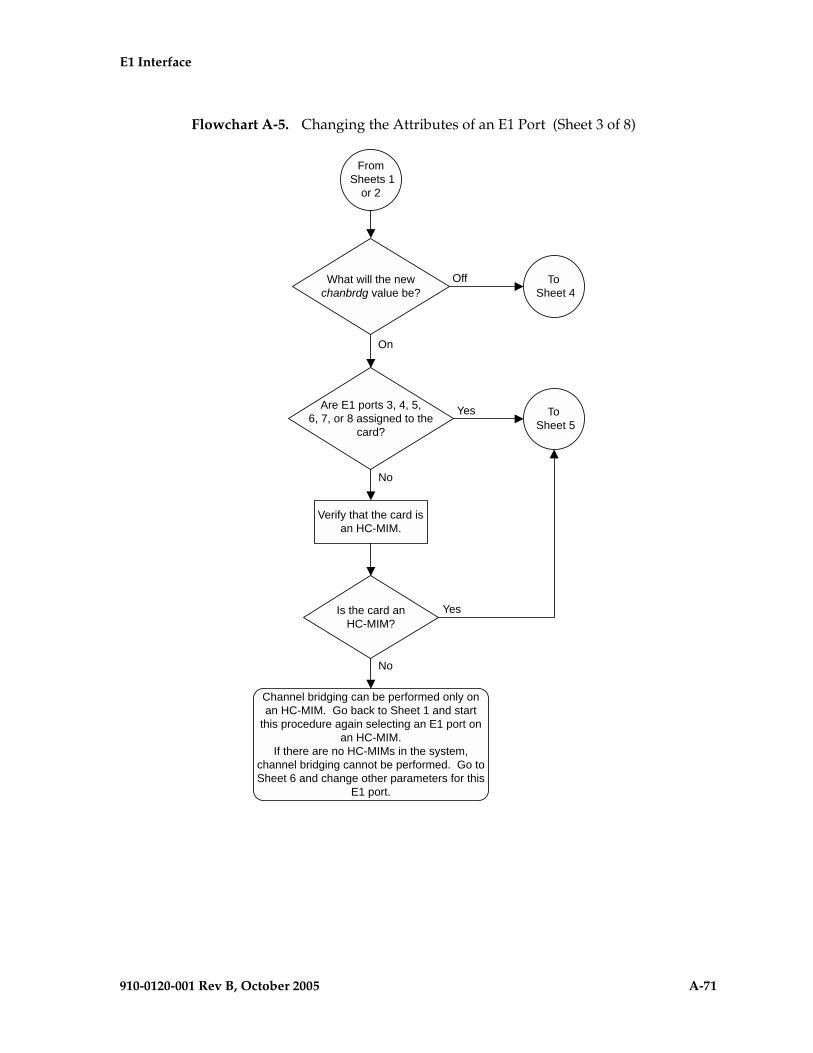
E1 Interface
910-0120-001 Rev B, October 2005 A-71
Flowchart A-5. Changing the Attributes of an E1 Port (Sheet 3 of 8)
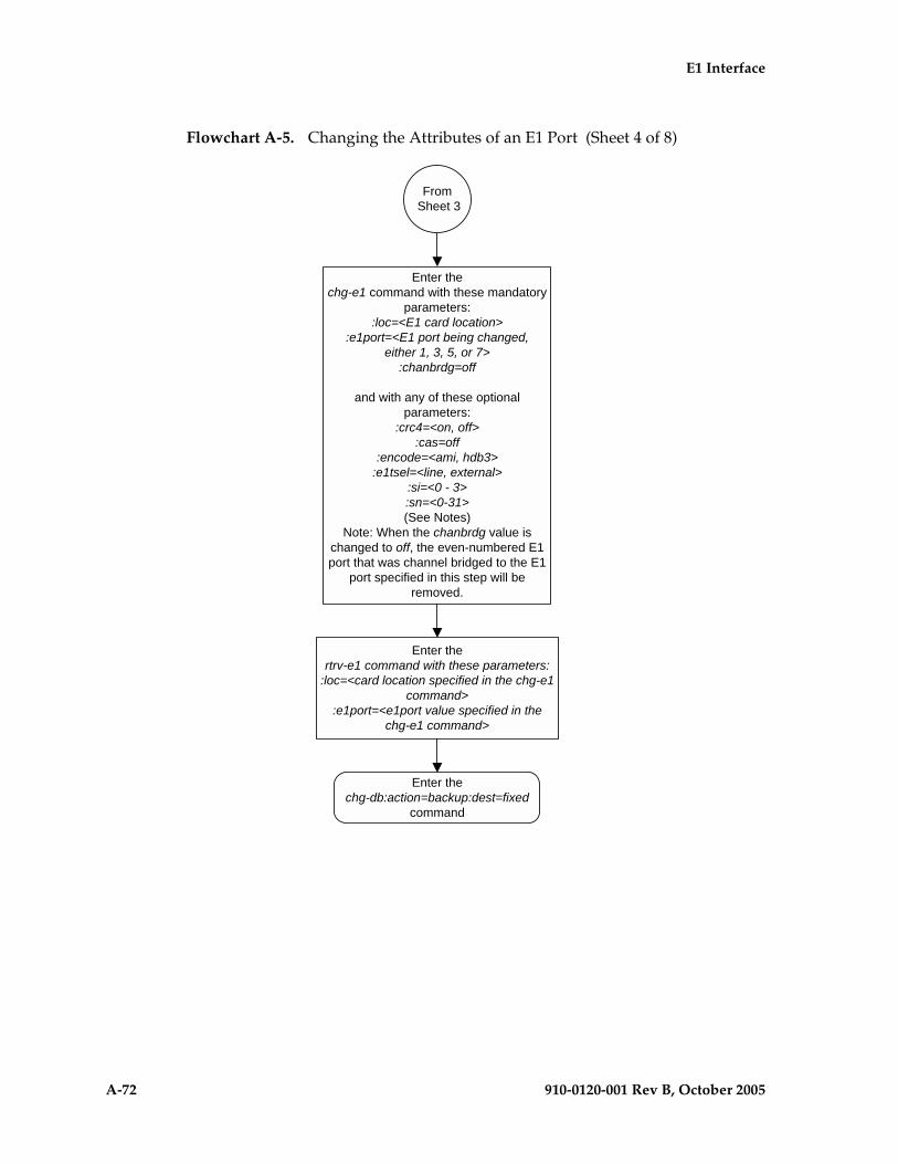
A-72 910-0120-001 Rev B, October 2005
E1 Interface
Flowchart A-5. Changing the Attributes of an E1 Port (Sheet 4 of 8)

E1 Interface
910-0120-001 Rev B, October 2005 A-73
Flowchart A-5. Changing the Attributes of an E1 Port (Sheet 5 of 8)
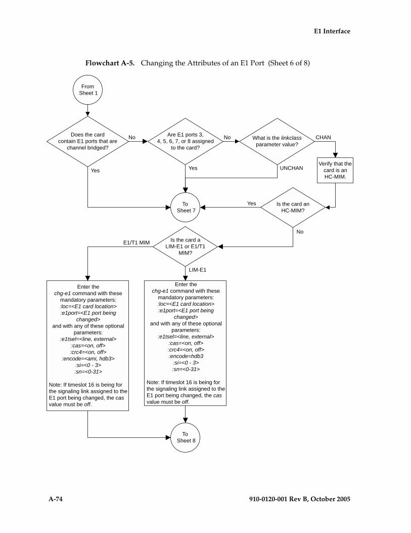
A-74 910-0120-001 Rev B, October 2005
E1 Interface
Flowchart A-5. Changing the Attributes of an E1 Port (Sheet 6 of 8)

E1 Interface
910-0120-001 Rev B, October 2005 A-75
Flowchart A-5. Changing the Attributes of an E1 Port (Sheet 7 of 8)

A-76 910-0120-001 Rev B, October 2005
E1 Interface
Flowchart A-5. Changing the Attributes of an E1 Port (Sheet 8 of 8)
E1 Interface
910-0120-001 Rev B, October 2005 A-77
Adding an E1 Signaling Link
This procedure is used to add an E1 signaling link to the database using the ent-slk command and these parameters.
:loc – The card location of the card that the E1 signaling link will be assigned to.
:link – The signaling link on the card specified in the loc parameter.
:lsn – The name of the linkset that will contain the signaling link.
:slc – The signaling link code. The SLC must be unique within the linkset. It must be the same at both the EAGLE 5 SAS location and the distant node.
:bps – The transmission rate for the link in bits per second.
:ecm – Error correction method, either basic or pcr. The default value for this parameter is basic.
:pcrn1 – The threshold of the number of MSUs available for retransmission. If the error correction method being used is PCR (:ecm=pcr), and this threshold is reached, no new MSUs or FISUs are sent. The retransmission cycle is continued up to the last MSU entered into the retransmission buffer in the order in which they were originally transmitted.
:pcrn2 – The threshold of the number of MSU octets available for retransmission. If the error correction method being used is PCR (:ecm=pcr), and this threshold is reached, no new MSUs or FISUs are sent. The retransmission cycle is continued up to the last MSU entered into the retransmission buffer in the order in which they were originally transmitted.
:ts – The timeslot on the E1 card or channel card being used for the E1 signaling link.
:e1port – The E1 port on the E1 card that is servicing the timeslot selected for the E1 signaling link.
:e1loc – The location of the E1 card servicing the timeslot selected for the E1 signaling link. This parameter can be specified only when provisioning E1 signaling links on channel cards.
:l2tset – The level 2 timer set table assigned to the E1 signaling link. The type of linkset the E1 signaling link is assigned to and the E1 card’s application determines the value of the l2tset parameter. The level 2 timer set tables are defined in the “Changing Level 2 Timers” procedure on page 3-219. Table A-15 on page A-78 shows the l2tset parameter values.

A-78 910-0120-001 Rev B, October 2005
E1 Interface
The ent-slk command contains other optional parameters that can be used to configure a signaling link. These parameters are not shown here because they are not necessary to provision an E1 signaling link. These parameters are explained in more detail in the “Adding an SS7 Signaling Link” procedure on page 3-130, or in the ent-slk command description in the Commands Manual.
These items must be configured in the database before an E1 signaling link can be added:
• Shelf – see “Adding a Shelf” in the Database Administration Manual - System Management
• E1 Card (card type lime1) or Channel Card (card type limch) running either the ss7ansi or ccs7itu applications – see “Adding a LIM-E1 Card” procedure on page A-14
• Destination Point Code – see the “Adding a Destination Point Code” procedure on page 2-191.
• Linkset – “Adding an SS7 Linkset” procedure on page 3-17.
Verify that the link has been physically installed (all cable connections have been made).
Table A-15. L2TSET Parameter Values
Type of Linkset E1 Card’s Application
L2TSET Parameter
Value
L2TSET Parameter
Default Value
ANSI linkset – Shown by this label in the rtrv-ls output.LSN APCA (SS7)
SS7ANSI 1 - 10 1
ITU linkset – Shown by one of these labels in the rtrv-ls output.LSN APCI (SS7)LSN APCN (SS7)LSN APCN24 (SS7)
CCS7ITU 11 - 20 11
ITU-N high-speed linkset for China – Shown by one of these labels in the rtrv-ls output.LSN (CHINA) APCN (SS7)LSN (CHINA) APCN24 (SS7)
CCS7ITU 21 - 25 21
ITU-N high-speed linkset for countries other than China – Shown by one of these labels in the rtrv-ls output.LSN APCN (SS7)LSN APCN24 (SS7)
CCS7ITU 26 - 30 26
E1 Interface
910-0120-001 Rev B, October 2005 A-79
Timeslot 16 (ts=16) cannot be specified for an E1 signaling link if the E1 interface servicing this link has CAS enabled. This is shown by the entry on in the CAS field of the rtrv-e1 output.
If the E1 signaling link is assigned to a channel card (card type limch), the e1port parameter cannot be specified. The e1port parameter value defaults to 1.
All E1 signaling links in a linkset can use either the 56000 or 64000 transmission rate. The transmission rate for the E1 signaling links in the linkset do not have to be the same.
The values for the ts parameter must be from 1 to 31.
The linkset must be in the database. The number of signaling links in a linkset cannot exceed 16. This can be verified with the rtrv-ls command.
The APC of the linkset assigned to the signaling link must be in the SS7 domain. Use the rtrv-dstn command to verify the domain of the APC of the linkset.
The pcrn1 or pcrn2 parameters can only be specified if the ecm=pcr parameter is specified.
If the E1 signaling link is being assigned to an unchannelized E1 port (shown by the entry UNCHAN in the LINKCLASS field in the rtrv-e1 output), you cannot specify the ts parameter. The link parameter value must be either a or b. The transmission rate (bps parameter) for an unchannelized E1 signaling link is 1984000 bits per second. The bps parameter is optional, and if not specified with the ent-slk command, the bps parameter value defaults to 1984000 bits per seconds.
If the E1 signaling link is being assigned to a channel bridged E1 port (shown by the entries MASTER or SLAVE in the CHANBRDG field in the rtrv-e1 output), the E1 port value for the signaling link must be the odd numbered (MASTER) E1 port.
If the E1 card is not an HC MIM, a maximum of 2 or 8 E1 signaling links can be assigned to the card. The range of link parameter values is dependent on the type of E1 card the signaling link is assigned to. If the E1 card is a LIM-E1 card, the link parameter values are either A or B, allowing a maximum of 2 signaling links on the card. If the E1 card is an E1/T1 MIM, the link parameter values are A - A3, or B - B3, allowing a maximum of 8 signaling links on the card.
If the E1 signaling link is being assigned to a channelized E1 port (shown by the entry CHAN in the LINKCLASS field in the rtrv-e1 output) on an HC MIM, the link parameter values are A - A31 or B - B31. An HC MIM can contain a maximum of 64 channelized E1 signaling links.
To configure the EAGLE 5 SAS to perform circular routing detection test on the signaling links, “Configuring Circular Route Detection” procedure on page 3-231.
NOTE: Circular route detection is not supported in ITU networks.

A-80 910-0120-001 Rev B, October 2005
E1 Interface
To provision a EAGLE 5 SAS with more than 700 signaling links, the EAGLE 5 SAS must have certain levels of hardware installed. See the “Requirements for EAGLE 5 SASs Containing more than 700 Signaling Links” section on page D-2 for more information on these hardware requirements.
The EAGLE 5 SAS can contain a mixture of low-speed, E1, T1, ATM high-speed, and IP signalling links. The “Determining the Number of High-Speed and Low-Speed Signaling Links” section on page D-2 describes how to determine the quantities of the different types of signaling links the EAGLE 5 SAS can have.
Configuring Signaling Links on LIM-E1 Cards
The main consideration for the provisioning of LIM-E1 cards into the EAGLE 5 SAS is to determine the number of LIM-E1 cards existing in the network and the equipment needed for expanding the signaling link capacity of the EAGLE 5 SAS. To utilize the flexibility of the E1 interface feature, you may want to determine the minimum number of LIM-E1 cards needed to process the total number of SS7 links and then consider diversity for reliability reasons.
Use the following points as guidelines when considering diversity for E1:
• If possible, no two LIM-E1 cards containing links from a common link set should be on the same E1/dual port Channel Card.
• If possible, no two LIM-E1 cards containing links from a common link set should be on adjacent E1/dual port Channel Cards where they are powered from the same fuse position.
• If possible, no two LIM-E1 cards containing links from a common link set should be terminated on the same shelf because of the shelf clock cabling, and is only an issue if using master clocking sync to the network
• If possible, no two links in a link set should arrive at the EAGLE 5 SAS on the same LIM-E1 card.
• If possible, for link sets containing more than two links, you should minimize the number of links in that link set on any given LIM-E1 card.
As an example, consider a network consisting of 30 LIM-E1 cards with a total number of 100 links where the largest link set size is 8. The most efficient way to provision the EAGLE 5 SAS would be to have 4 extension shelves equipped with the E1 Cabling Backplane, 1 E1 Card, and 12 Channel Cards per shelf. Utilizing 1 “B” bus on each shelf, 25 signaling links would be terminated on each shelf for a total of 100. This is also the minimum number of LIM-E1 Cards required for this example.
With the same example but using the third and fifth bullets above as a consideration, the EAGLE 5 SAS would be provisioned with 8 extension shelves equipped with the E1 Cabling Backplane. Four of the shelves would be equipped with 1 E1 Card and 6 Channel Cards, and the other 4 shelves would be equipped with 1 E1 Card and 5 Channel Cards. Since the largest link set size is 8, a total of 8 LIM-E1 Cards is required. Utilizing 1 “B” bus on each shelf, 13 signaling links
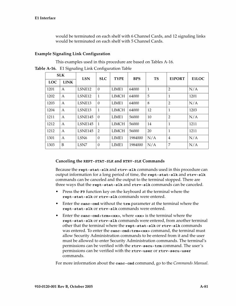
E1 Interface
910-0120-001 Rev B, October 2005 A-81
would be terminated on each shelf with 6 Channel Cards, and 12 signaling links would be terminated on each shelf with 5 Channel Cards.
Example Signaling Link Configuration
This examples used in this procedure are based on Tables A-16.
Canceling the REPT-STAT-SLK and RTRV-SLK Commands
Because the rept-stat-slk and rtrv-slk commands used in this procedure can output information for a long period of time, the rept-stat-slk and rtrv-slk commands can be canceled and the output to the terminal stopped. There are three ways that the rept-stat-slk and rtrv-slk commands can be canceled.
• Press the F9 function key on the keyboard at the terminal where the rept-stat-slk or rtrv-slk commands were entered.
• Enter the canc-cmd without the trm parameter at the terminal where the rept-stat-slk or rtrv-slk commands were entered.
• Enter the canc-cmd:trm=<xx>, where <xx> is the terminal where the rept-stat-slk or rtrv-slk commands were entered, from another terminal other that the terminal where the rept-stat-slk or rtrv-slk commands was entered. To enter the canc-cmd:trm=<xx> command, the terminal must allow Security Administration commands to be entered from it and the user must be allowed to enter Security Administration commands. The terminal’s permissions can be verified with the rtrv-secu-trm command. The user’s permissions can be verified with the rtrv-user or rtrv-secu-user commands.
For more information about the canc-cmd command, go to the Commands Manual.
Table A-16. E1 Signaling Link Configuration Table
SLKLSN SLC TYPE BPS TS E1PORT E1LOC
LOC LINK
1201 A LSNE12 0 LIME1 64000 1 2 N/A
1202 A LSNE12 1 LIMCH 64000 5 1 1201
1203 A LSNE13 0 LIME1 64000 8 2 N/A
1204 A LSNE13 1 LIMCH 64000 12 1 1203
1211 A LSNE145 0 LIME1 56000 10 2 N/A
1212 A LSNE145 1 LIMCH 56000 14 1 1211
1212 A LSNE145 2 LIMCH 56000 20 1 1211
1301 A LSN6 0 LIME1 1984000 N/A 4 N/A
1303 B LSN7 0 LIME1 1984000 N/A 7 N/A

A-82 910-0120-001 Rev B, October 2005
E1 Interface
Procedure
1. Display the cards in the database using the rtrv-card command. This is an example of the possible output.
rlghncxa03w 05-09-28 09:12:36 GMT EAGLE5 34.0.0CARD TYPE APPL LSET NAME LINK SLC LSET NAME LINK SLC1101 TSM SCCP 1102 TSM GLS 1113 GSPM EOAM1114 TDM-A1115 GSPM EOAM1116 TDM-B1117 MDAL1201 LIME1 CCS7ITU 1202 LIMCH CCS7ITU 1203 LIME1 CCS7ITU 1204 LIMCH CCS7ITU 1211 LIME1 CCS7ITU 1212 LIMCH CCS7ITU 1305 LIMOCU CCS7ITU sp6 A 0 sp7 B 01306 LIMOCU CCS7ITU nsp3 A 0 nsp4 B 01307 LIMOCU CCS7ITU nsp1 A 0 1308 LIMOCU CCS7ITU nsp1 A 1 1316 ACMENET STPLAN 1314 LIMOCU CCS7ITU sp7 A 1 sp5 B 01317 TSM SCCP
If the required E1 card or channel card is not in the database, go to the “Adding a LIM-E1 Card” procedure on page A-14 and add the required cards to the database.
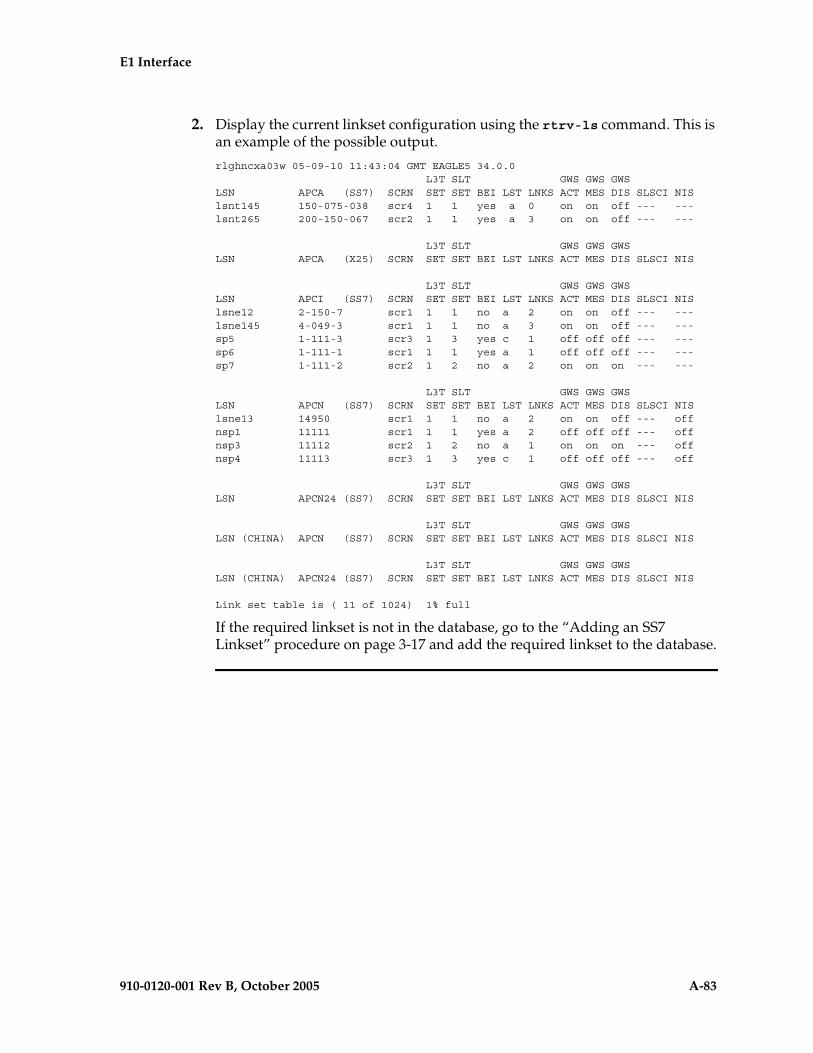
E1 Interface
910-0120-001 Rev B, October 2005 A-83
2. Display the current linkset configuration using the rtrv-ls command. This is an example of the possible output.
rlghncxa03w 05-09-10 11:43:04 GMT EAGLE5 34.0.0 L3T SLT GWS GWS GWSLSN APCA (SS7) SCRN SET SET BEI LST LNKS ACT MES DIS SLSCI NISlsnt145 150-075-038 scr4 1 1 yes a 0 on on off --- ---lsnt265 200-150-067 scr2 1 1 yes a 3 on on off --- ---
L3T SLT GWS GWS GWSLSN APCA (X25) SCRN SET SET BEI LST LNKS ACT MES DIS SLSCI NIS
L3T SLT GWS GWS GWSLSN APCI (SS7) SCRN SET SET BEI LST LNKS ACT MES DIS SLSCI NISlsne12 2-150-7 scr1 1 1 no a 2 on on off --- ---lsne145 4-049-3 scr1 1 1 no a 3 on on off --- ---sp5 1-111-3 scr3 1 3 yes c 1 off off off --- ---sp6 1-111-1 scr1 1 1 yes a 1 off off off --- ---sp7 1-111-2 scr2 1 2 no a 2 on on on --- ---
L3T SLT GWS GWS GWSLSN APCN (SS7) SCRN SET SET BEI LST LNKS ACT MES DIS SLSCI NISlsne13 14950 scr1 1 1 no a 2 on on off --- offnsp1 11111 scr1 1 1 yes a 2 off off off --- offnsp3 11112 scr2 1 2 no a 1 on on on --- offnsp4 11113 scr3 1 3 yes c 1 off off off --- off
L3T SLT GWS GWS GWSLSN APCN24 (SS7) SCRN SET SET BEI LST LNKS ACT MES DIS SLSCI NIS
L3T SLT GWS GWS GWSLSN (CHINA) APCN (SS7) SCRN SET SET BEI LST LNKS ACT MES DIS SLSCI NIS
L3T SLT GWS GWS GWSLSN (CHINA) APCN24 (SS7) SCRN SET SET BEI LST LNKS ACT MES DIS SLSCI NIS
Link set table is ( 11 of 1024) 1% full
If the required linkset is not in the database, go to the “Adding an SS7 Linkset” procedure on page 3-17 and add the required linkset to the database.

A-84 910-0120-001 Rev B, October 2005
E1 Interface
3. Display the current signaling link configuration using the rtrv-slk command. This is an example of the possible output.
rlghncxa03w 05-09-19 21:16:37 GMT EAGLE5 34.0.0 L2T L1 PCR PCRLOC LINK LSN SLC TYPE SET BPS MODE TSET ECM N1 N21305 A sp6 0 LIMOCU 1 56000 --- --- BASIC --- -----1305 B sp7 0 LIMOCU 1 64000 DTE --- PCR 76 38001306 A nsp3 0 LIMOCU 1 56000 --- --- BASIC --- -----1306 B nsp4 0 LIMOCU 1 56000 --- --- BASIC --- -----1307 A nsp1 0 LIMOCU 1 56000 --- --- BASIC --- -----1308 A nsp1 1 LIMOCU 1 56000 --- --- BASIC --- -----1314 A sp7 1 LIMOCU 2 64000 DTE --- PCR 76 38001314 B sp5 0 LIMOCU 3 64000 DCE ON BASIC --- -----
LP ATMLOC LINK LSN SLC TYPE SET BPS TSEL VCI VPI LL
LP ATM E1ATMLOC LINK LSN SLC TYPE SET BPS TSEL VCI VPI CRC4 SI SN
No Links Set up.
LOC LINK LSN SLC TYPE IPLIML2
No Links Set up.
LOC LINK LSN SLC TYPE
No Links Set up.
L2T PCR PCR E1 E1LOC LINK LSN SLC TYPE SET BPS ECM N1 N2 LOC PORT TS
No Links Set up.
L2T PCR PCR T1 T1LOC LINK LSN SLC TYPE SET BPS ECM N1 N2 LOC PORT TS
No Links Set up.
SLK table is (8 of 1200) 1% full.
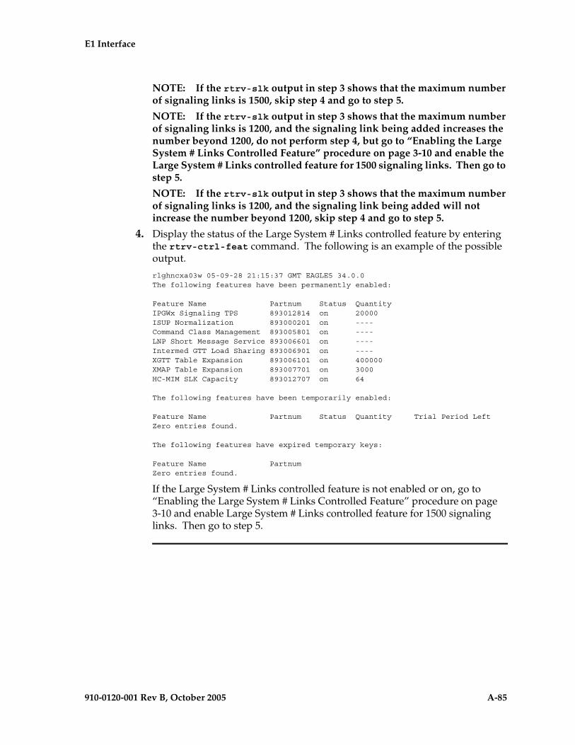
E1 Interface
910-0120-001 Rev B, October 2005 A-85
NOTE: If the rtrv-slk output in step 3 shows that the maximum number of signaling links is 1500, skip step 4 and go to step 5.
NOTE: If the rtrv-slk output in step 3 shows that the maximum number of signaling links is 1200, and the signaling link being added increases the number beyond 1200, do not perform step 4, but go to “Enabling the Large System # Links Controlled Feature” procedure on page 3-10 and enable the Large System # Links controlled feature for 1500 signaling links. Then go to step 5.
NOTE: If the rtrv-slk output in step 3 shows that the maximum number of signaling links is 1200, and the signaling link being added will not increase the number beyond 1200, skip step 4 and go to step 5.
4. Display the status of the Large System # Links controlled feature by entering the rtrv-ctrl-feat command. The following is an example of the possible output.
rlghncxa03w 05-09-28 21:15:37 GMT EAGLE5 34.0.0The following features have been permanently enabled:
Feature Name Partnum Status QuantityIPGWx Signaling TPS 893012814 on 20000ISUP Normalization 893000201 on ----Command Class Management 893005801 on ----LNP Short Message Service 893006601 on ----Intermed GTT Load Sharing 893006901 on ----XGTT Table Expansion 893006101 on 400000XMAP Table Expansion 893007701 on 3000HC-MIM SLK Capacity 893012707 on 64
The following features have been temporarily enabled:
Feature Name Partnum Status Quantity Trial Period LeftZero entries found.
The following features have expired temporary keys:
Feature Name PartnumZero entries found.
If the Large System # Links controlled feature is not enabled or on, go to “Enabling the Large System # Links Controlled Feature” procedure on page 3-10 and enable Large System # Links controlled feature for 1500 signaling links. Then go to step 5.

A-86 910-0120-001 Rev B, October 2005
E1 Interface
5. Display the E1 interfaces that will be assigned to the E1 signaling link using the rtrv-e1 command with no parameters. This is an example of the possible output.
rlghncxa03w 05-09-19 21:17:04 GMT EAGLE5 34.0.0
E1 LINK MINSULOC PORT CRC4 CAS ENCODE E1TSEL SI SN CHANBRDG CLASS RATE1201 2 ON OFF HDB3 LINE 0 0 ------ CHAN ----1203 1 OFF ON HDB3 EXTERNAL 3 6 ------ CHAN ----1211 2 ON OFF HDB3 LINE 0 0 ------ CHAN ----
If the desired E1 port and E1 card combination are not shown in the rtrv-e1 output, add the E1 port and E1 card combination to the database by performing the one of these procedures:
• “Adding Channelized and non-Channel Bridged E1 Ports” procedure on page A-28.
• “Adding Channel Bridged E1 Ports” procedure on page A-37.
• “Adding Unchannelized E1 Ports” procedure on page A-45.
If a new E1 card was added in these procedures and that card is an HC MIM, skip step 6 and go to step 7.
NOTE: If the card the signaling link is being assigned to is a channel card, skip step 6, and go to step 7.
6. If any of the following conditions are shown in the rtrv-e1 output in step 5, the card is an HC MIM.
a. The linkclass=unchan parameter is assigned to the E1 port that will be assigned to the E1 signaling link. Go to step 7.
b. If the E1 port that will be assigned to the E1 signaling link is channel bridged. Go to step 7.
c. If E1 ports 3, 4, 5, 6, 7, or 8 are assigned to the E1 card that will be assigned to the E1 signaling link. Go to step 7.
If conditions a, b , or c are not shown in the rtrv-e1 output, verify the type of E1 card.
7. Add the E1 signaling links using the ent-slk command.
If the output of step 5 shows that CAS is enabled for the E1 interface (shown by the entry on in the CAS field), timeslot 16 cannot be specified for the E1 signaling link.
The link parameter value is dependent on the type of card the E1 signaling link is assigned to. Table A-17 shows the link parameter values.

E1 Interface
910-0120-001 Rev B, October 2005 A-87
If the E1 signaling link is being assigned to an unchannelized E1 port (shown by the entries UNCHAN in the LINKCLASS field in the rtrv-e1 output), you cannot specify the ts parameter. The transmission rate (bps parameter) for an unchannelized E1 signaling link is 1984000 bits per second. The bps parameter is optional, and if not specified with the ent-slk command, the bps parameter value defaults to 1984000 bits per seconds.
It is recommended that unchannelized E1 signaling links are assigned to linksets that do not contain other types of signaling links.
For this example, enter these commands.
ent-slk:loc=1201:link=a:lsn=lsne12:slc=0:bps=64000:ts=1:e1port=2
ent-slk:loc=1202:link=a:lsn=lsne12:slc=1:bps=64000:ts=5:e1loc=1201
ent-slk:loc=1203:link=a:lsn=lsne13:slc=0:bps=64000:ts=8:e1port=2
ent-slk:loc=1204:link=a:lsn=lsne13:slc=1:bps=64000:ts=12:e1loc=1203
ent-slk:loc=1211:link=a:lsn=lsne145:slc=0:bps=56000:ts=10:e1port=2
ent-slk:loc=1212:link=a:lsn=lsne145:slc=1:bps=56000:ts=14:e1loc=1211
ent-slk:loc=1212:link=a2:lsn=lsne145:slc=2:bps=56000:ts=20:e1loc=1211
ent-slk:loc=1301:link=a:lsn=lsn6:slc=0:e1port=4
ent-slk:loc=1303:link=b:lsn=lsn7:slc=0:e1port=7
When each of these commands have successfully completed, this message should appear.
rlghncxa03w 05-09-07 08:29:03 GMT EAGLE5 34.0.0ENT-SLK: MASP A - COMPLTD
Table A-17. Link Parameter Values
Type of Card Link Parameter Values
LIM-E1 A or B
E1/T1 MIM A - A3, B - B3
HC MIM A - A31, B - B31
HC MIM containing an unchannelized E1 port A or B

A-88 910-0120-001 Rev B, October 2005
E1 Interface
8. Verify the changes using the rtrv-slk command, specifying the card location and signaling link entered in step 7. This is an example of the possible output.
rtrv-slk:loc=1201:link=a
This is an example of the possible output.rlghncxa03w 05-09-19 21:17:04 GMT EAGLE5 34.0.0 L2T PCR PCR E1 E1LOC LINK LSN SLC TYPE SET BPS ECM N1 N2 LOC PORT TS1201 A lsne12 0 LIME1 1 64000 BASIC --- ----- 1201 2 1
rtrv-slk:loc=1202:link=a
This is an example of the possible output.rlghncxa03w 05-09-19 21:17:04 GMT EAGLE5 34.0.0 L2T PCR PCR E1 E1LOC LINK LSN SLC TYPE SET BPS ECM N1 N2 LOC PORT TS1202 A lsne12 1 LIMCH 1 64000 BASIC --- ----- 1201 1 5
rtrv-slk:loc=1203:link=a
This is an example of the possible output.rlghncxa03w 05-09-19 21:17:04 GMT EAGLE5 34.0.0 L2T PCR PCR E1 E1LOC LINK LSN SLC TYPE SET BPS ECM N1 N2 LOC PORT TS1203 A lsne13 0 LIME1 1 64000 BASIC --- ----- 1203 2 8
rtrv-slk:loc=1204:link=a
This is an example of the possible output.rlghncxa03w 05-09-19 21:17:04 GMT EAGLE5 34.0.0 L2T PCR PCR E1 E1LOC LINK LSN SLC TYPE SET BPS ECM N1 N2 LOC PORT TS1204 A lsne13 1 LIMCH 1 64000 BASIC --- ----- 1203 1 12
rtrv-slk:loc=1211:link=a
This is an example of the possible output.rlghncxa03w 05-09-19 21:17:04 GMT EAGLE5 34.0.0 L2T PCR PCR E1 E1LOC LINK LSN SLC TYPE SET BPS ECM N1 N2 LOC PORT TS1211 A lsne145 0 LIME1 1 56000 BASIC --- ----- 1211 2 10
rtrv-slk:loc=1212:link=a
This is an example of the possible output.rlghncxa03w 05-09-19 21:17:04 GMT EAGLE5 34.0.0 L2T PCR PCR E1 E1LOC LINK LSN SLC TYPE SET BPS ECM N1 N2 LOC PORT TS1212 A lsne145 1 LIMCH 1 56000 BASIC --- ----- 1211 1 14
rtrv-slk:loc=1212:link=a2
This is an example of the possible output.rlghncxa03w 05-09-19 21:17:04 GMT EAGLE5 34.0.0 L2T PCR PCR E1 E1LOC LINK LSN SLC TYPE SET BPS ECM N1 N2 LOC PORT TS1212 A2 lsne145 2 LIMCH 1 56000 BASIC --- ----- 1211 1 20
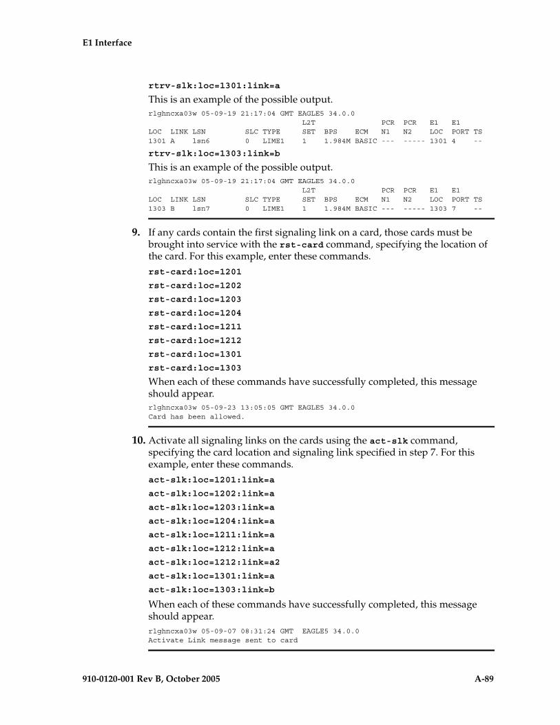
E1 Interface
910-0120-001 Rev B, October 2005 A-89
rtrv-slk:loc=1301:link=a
This is an example of the possible output.rlghncxa03w 05-09-19 21:17:04 GMT EAGLE5 34.0.0 L2T PCR PCR E1 E1LOC LINK LSN SLC TYPE SET BPS ECM N1 N2 LOC PORT TS1301 A lsn6 0 LIME1 1 1.984M BASIC --- ----- 1301 4 --
rtrv-slk:loc=1303:link=b
This is an example of the possible output.rlghncxa03w 05-09-19 21:17:04 GMT EAGLE5 34.0.0 L2T PCR PCR E1 E1LOC LINK LSN SLC TYPE SET BPS ECM N1 N2 LOC PORT TS1303 B lsn7 0 LIME1 1 1.984M BASIC --- ----- 1303 7 --
9. If any cards contain the first signaling link on a card, those cards must be brought into service with the rst-card command, specifying the location of the card. For this example, enter these commands.rst-card:loc=1201
rst-card:loc=1202
rst-card:loc=1203
rst-card:loc=1204
rst-card:loc=1211
rst-card:loc=1212
rst-card:loc=1301
rst-card:loc=1303
When each of these commands have successfully completed, this message should appear.rlghncxa03w 05-09-23 13:05:05 GMT EAGLE5 34.0.0Card has been allowed.
10. Activate all signaling links on the cards using the act-slk command, specifying the card location and signaling link specified in step 7. For this example, enter these commands.act-slk:loc=1201:link=a
act-slk:loc=1202:link=a
act-slk:loc=1203:link=a
act-slk:loc=1204:link=a
act-slk:loc=1211:link=a
act-slk:loc=1212:link=a
act-slk:loc=1212:link=a2
act-slk:loc=1301:link=a
act-slk:loc=1303:link=b
When each of these commands have successfully completed, this message should appear.rlghncxa03w 05-09-07 08:31:24 GMT EAGLE5 34.0.0Activate Link message sent to card

A-90 910-0120-001 Rev B, October 2005
E1 Interface
11. Check the status of the signaling links added in step 7 using the rept-stat-slk command with the card location and signaling link. The state of each signaling link should be in service normal (IS-NR) after the link has completed alignment (shown in the PST field). For this example, enter these commands.
rept-stat-slk:loc=1201:link=a
This is an example of the possible output.
rlghncxa03w 05-09-23 13:06:25 GMT EAGLE5 34.0.0SLK LSN CLLI PST SST AST1201,A lsne12 ----------- IS-NR Avail ---- ALARM STATUS = No Alarms UNAVAIL REASON = -- E1 status = 1201, RCVRY-E1F:FAC-E1 Port 2 available
rept-stat-slk:loc=1202:link=a
This is an example of the possible output.
rlghncxa03w 05-09-23 13:06:25 GMT EAGLE5 34.0.0SLK LSN CLLI PST SST AST1202,A lsne12 ----------- IS-NR Avail ---- ALARM STATUS = No Alarms UNAVAIL REASON = -- E1 status = 1201, RCVRY-E1F:FAC-E1 Port 1 available
rept-stat-slk:loc=1203:link=a
This is an example of the possible output.
rlghncxa03w 05-09-23 13:06:25 GMT EAGLE5 34.0.0SLK LSN CLLI PST SST AST1203,A lsne12 ----------- IS-NR Avail ---- ALARM STATUS = No Alarms UNAVAIL REASON = -- E1 status = 1203, RCVRY-E1F:FAC-E1 Port 2 available
rept-stat-slk:loc=1204:link=a
This is an example of the possible output.
rlghncxa03w 05-09-23 13:06:25 GMT EAGLE5 34.0.0SLK LSN CLLI PST SST AST1204,A lsne12 ----------- IS-NR Avail ---- ALARM STATUS = No Alarms UNAVAIL REASON = -- E1 status = 1203, RCVRY-E1F:FAC-E1 Port 1 available
rept-stat-slk:loc=1211:link=a
This is an example of the possible output.
rlghncxa03w 05-09-23 13:06:25 GMT EAGLE5 34.0.0SLK LSN CLLI PST SST AST1211,A lsne145 ----------- IS-NR Avail ---- ALARM STATUS = No Alarms UNAVAIL REASON = -- E1 status = 1211, RCVRY-E1F:FAC-E1 Port 2 available
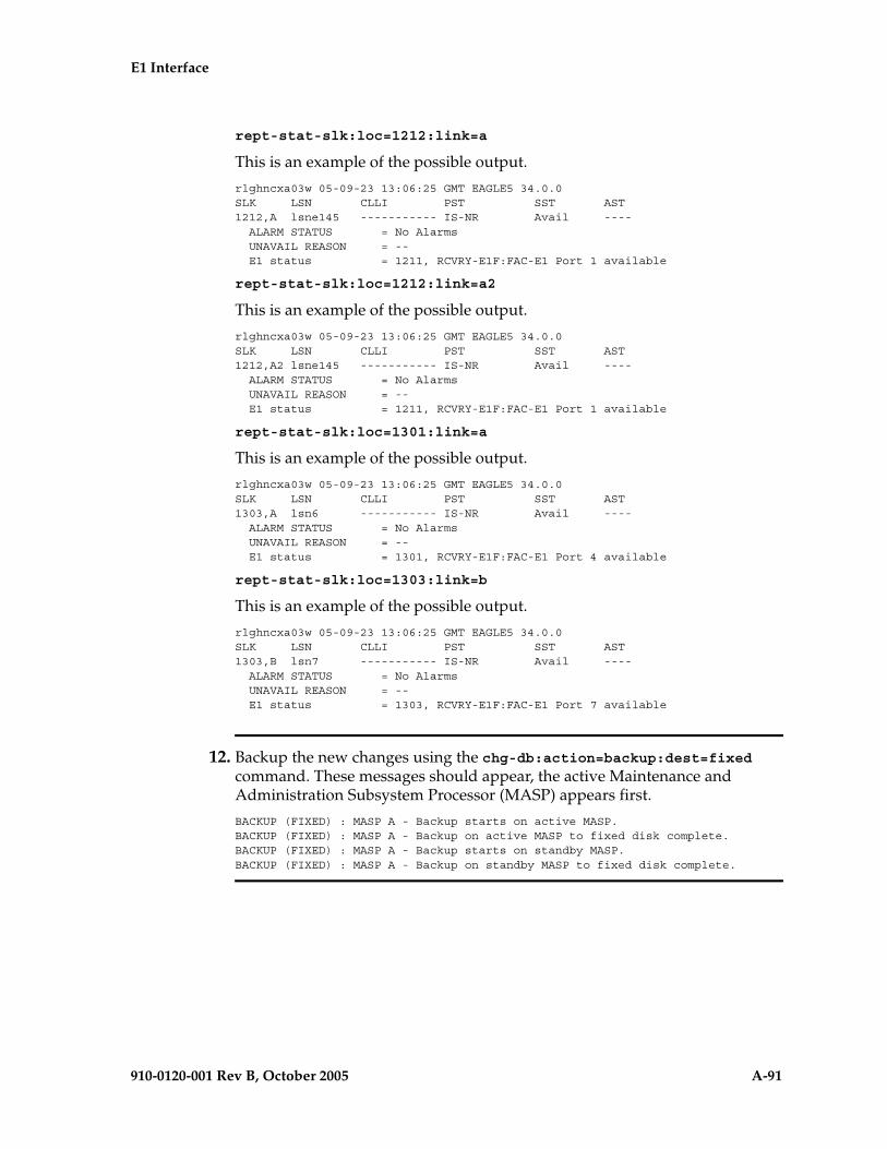
E1 Interface
910-0120-001 Rev B, October 2005 A-91
rept-stat-slk:loc=1212:link=a
This is an example of the possible output.
rlghncxa03w 05-09-23 13:06:25 GMT EAGLE5 34.0.0SLK LSN CLLI PST SST AST1212,A lsne145 ----------- IS-NR Avail ---- ALARM STATUS = No Alarms UNAVAIL REASON = -- E1 status = 1211, RCVRY-E1F:FAC-E1 Port 1 available
rept-stat-slk:loc=1212:link=a2
This is an example of the possible output.
rlghncxa03w 05-09-23 13:06:25 GMT EAGLE5 34.0.0SLK LSN CLLI PST SST AST1212,A2 lsne145 ----------- IS-NR Avail ---- ALARM STATUS = No Alarms UNAVAIL REASON = -- E1 status = 1211, RCVRY-E1F:FAC-E1 Port 1 available
rept-stat-slk:loc=1301:link=a
This is an example of the possible output.
rlghncxa03w 05-09-23 13:06:25 GMT EAGLE5 34.0.0SLK LSN CLLI PST SST AST1303,A lsn6 ----------- IS-NR Avail ---- ALARM STATUS = No Alarms UNAVAIL REASON = -- E1 status = 1301, RCVRY-E1F:FAC-E1 Port 4 available
rept-stat-slk:loc=1303:link=b
This is an example of the possible output.
rlghncxa03w 05-09-23 13:06:25 GMT EAGLE5 34.0.0SLK LSN CLLI PST SST AST1303,B lsn7 ----------- IS-NR Avail ---- ALARM STATUS = No Alarms UNAVAIL REASON = -- E1 status = 1303, RCVRY-E1F:FAC-E1 Port 7 available
12. Backup the new changes using the chg-db:action=backup:dest=fixed command. These messages should appear, the active Maintenance and Administration Subsystem Processor (MASP) appears first.
BACKUP (FIXED) : MASP A - Backup starts on active MASP.BACKUP (FIXED) : MASP A - Backup on active MASP to fixed disk complete.BACKUP (FIXED) : MASP A - Backup starts on standby MASP.BACKUP (FIXED) : MASP A - Backup on standby MASP to fixed disk complete.
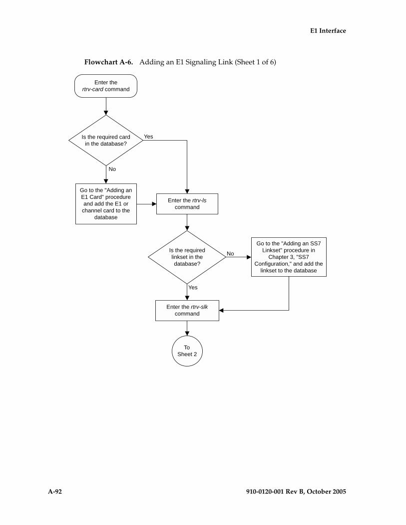
A-92 910-0120-001 Rev B, October 2005
E1 Interface
Flowchart A-6. Adding an E1 Signaling Link (Sheet 1 of 6)

E1 Interface
910-0120-001 Rev B, October 2005 A-93
Flowchart A-6. Adding an E1 Signaling Link (Sheet 2 of 6)

A-94 910-0120-001 Rev B, October 2005
E1 Interface
Flowchart A-6. Adding an E1 Signaling Link (Sheet 3 of 6)

E1 Interface
910-0120-001 Rev B, October 2005 A-95
Flowchart A-6. Adding an E1 Signaling Link (Sheet 4 of 6)
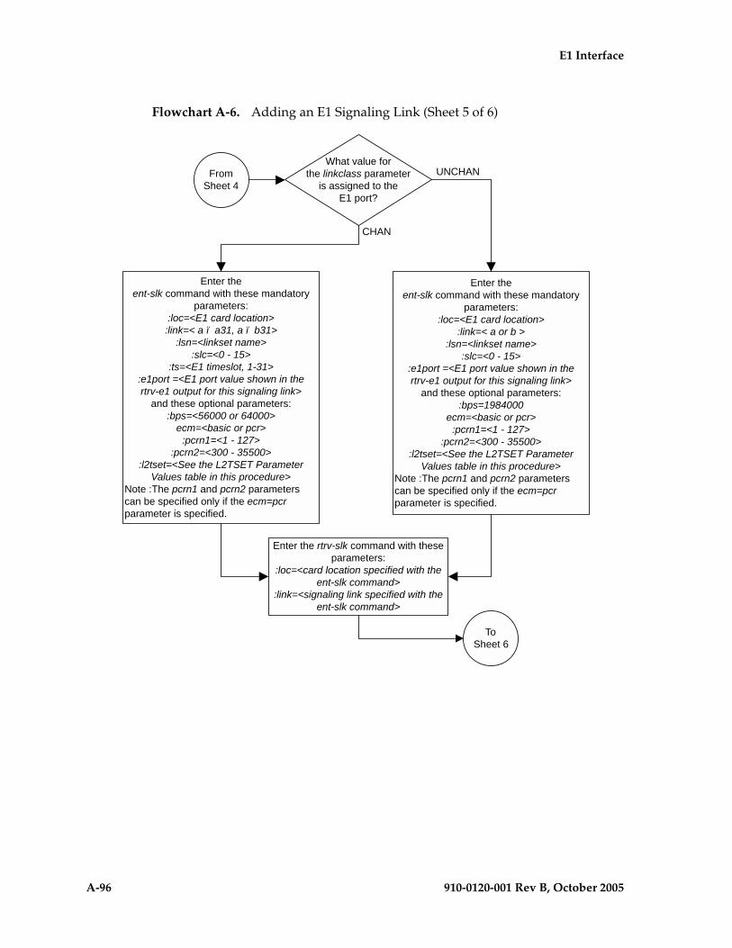
A-96 910-0120-001 Rev B, October 2005
E1 Interface
Flowchart A-6. Adding an E1 Signaling Link (Sheet 5 of 6)

E1 Interface
910-0120-001 Rev B, October 2005 A-97
Flowchart A-6. Adding an E1 Signaling Link (Sheet 6 of 6)

A-98 910-0120-001 Rev B, October 2005
E1 Interface

910-0120-001 Rev B, October 2005 B-1
B
T1 Interface
Introduction......................................................................................................B–2
Determining the Configuration.....................................................................B–7
Adding a LIM-T1 Card .................................................................................B–11
Removing a LIM-T1 Card.............................................................................B–20
Adding the T1 Interface Parameters ...........................................................B–24
Removing the T1 Interface Parameters ......................................................B–33
Changing the T1 Interface Parameters .......................................................B–36
Adding a T1 Signaling Link .........................................................................B–47

B-2 910-0120-001 Rev B, October 2005
T1 Interface
Introduction
The T1 interface terminates or distributes T1 facility signals for the purpose of processing the SS7 signaling links carried by the T1 carrier. The T1 interface can be either an E1/T1 MIM or an HC MIM as shown in Figures B-1 and B-2. The E1/T1 MIM or HC MIM can also be used as an E1 interface. This appendix describes how the T1 interface is configured. The E1 interface configuration is described in Appendix A, “E1 Interface.” The E1/T1 MIM contain up to eight signaling links and allows the EAGLE 5 SAS to contain more than 500 signaling links.
Figure B-1. E1/T1 MIM Block Diagram
E1/T1 Control Internals
A A1
B3 B2 B1
B A3 A2
SLK PortsApplication Interface
Support Data
Interface A
Interface B
E1/T1Port 1
E1/T1Port 2
E1/T1 Control Internals
A A1
B3 B2 B1
B A3 A2
SLK PortsApplication Interface
Support Data
Interface A
Interface B
ExternalE1/T1
Backplane
E1/T1 MIM Provisioned as a LIME1 or LIMT1
E1/T1 MIM Provisioned as a LIMCH
E1/T1Line 1
E1/T1Line 2
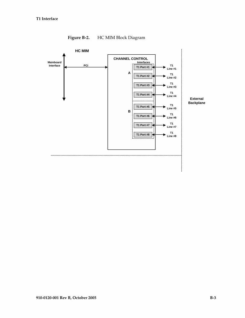
T1 Interface
910-0120-001 Rev B, October 2005 B-3
Figure B-2. HC MIM Block Diagram
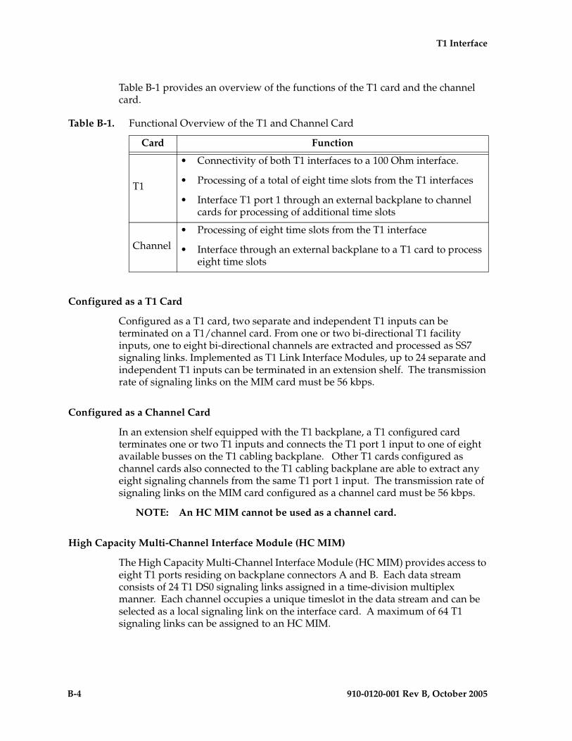
B-4 910-0120-001 Rev B, October 2005
T1 Interface
Table B-1 provides an overview of the functions of the T1 card and the channel card.
Configured as a T1 Card
Configured as a T1 card, two separate and independent T1 inputs can be terminated on a T1/channel card. From one or two bi-directional T1 facility inputs, one to eight bi-directional channels are extracted and processed as SS7 signaling links. Implemented as T1 Link Interface Modules, up to 24 separate and independent T1 inputs can be terminated in an extension shelf. The transmission rate of signaling links on the MIM card must be 56 kbps.
Configured as a Channel Card
In an extension shelf equipped with the T1 backplane, a T1 configured card terminates one or two T1 inputs and connects the T1 port 1 input to one of eight available busses on the T1 cabling backplane. Other T1 cards configured as channel cards also connected to the T1 cabling backplane are able to extract any eight signaling channels from the same T1 port 1 input. The transmission rate of signaling links on the MIM card configured as a channel card must be 56 kbps.
NOTE: An HC MIM cannot be used as a channel card.
High Capacity Multi-Channel Interface Module (HC MIM)
The High Capacity Multi-Channel Interface Module (HC MIM) provides access to eight T1 ports residing on backplane connectors A and B. Each data stream consists of 24 T1 DS0 signaling links assigned in a time-division multiplex manner. Each channel occupies a unique timeslot in the data stream and can be selected as a local signaling link on the interface card. A maximum of 64 T1 signaling links can be assigned to an HC MIM.
Table B-1. Functional Overview of the T1 and Channel Card
Card Function
T1
• Connectivity of both T1 interfaces to a 100 Ohm interface.
• Processing of a total of eight time slots from the T1 interfaces
• Interface T1 port 1 through an external backplane to channel cards for processing of additional time slots
Channel
• Processing of eight time slots from the T1 interface
• Interface through an external backplane to a T1 card to process eight time slots
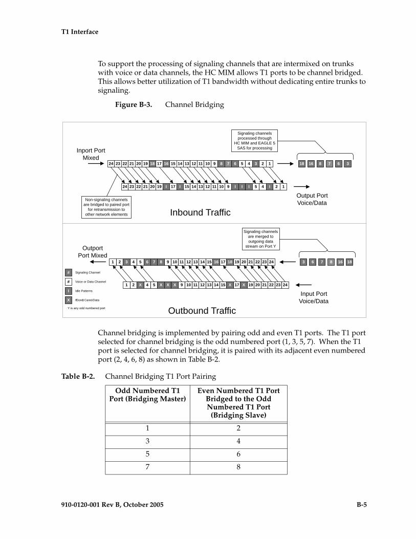
T1 Interface
910-0120-001 Rev B, October 2005 B-5
To support the processing of signaling channels that are intermixed on trunks with voice or data channels, the HC MIM allows T1 ports to be channel bridged. This allows better utilization of T1 bandwidth without dedicating entire trunks to signaling.
Figure B-3. Channel Bridging
Channel bridging is implemented by pairing odd and even T1 ports. The T1 port selected for channel bridging is the odd numbered port (1, 3, 5, 7). When the T1 port is selected for channel bridging, it is paired with its adjacent even numbered port (2, 4, 6, 8) as shown in Table B-2.
Table B-2. Channel Bridging T1 Port Pairing
Odd Numbered T1 Port (Bridging Master)
Even Numbered T1 Port Bridged to the Odd Numbered T1 Port
(Bridging Slave)
1 2
3 4
5 6
7 8
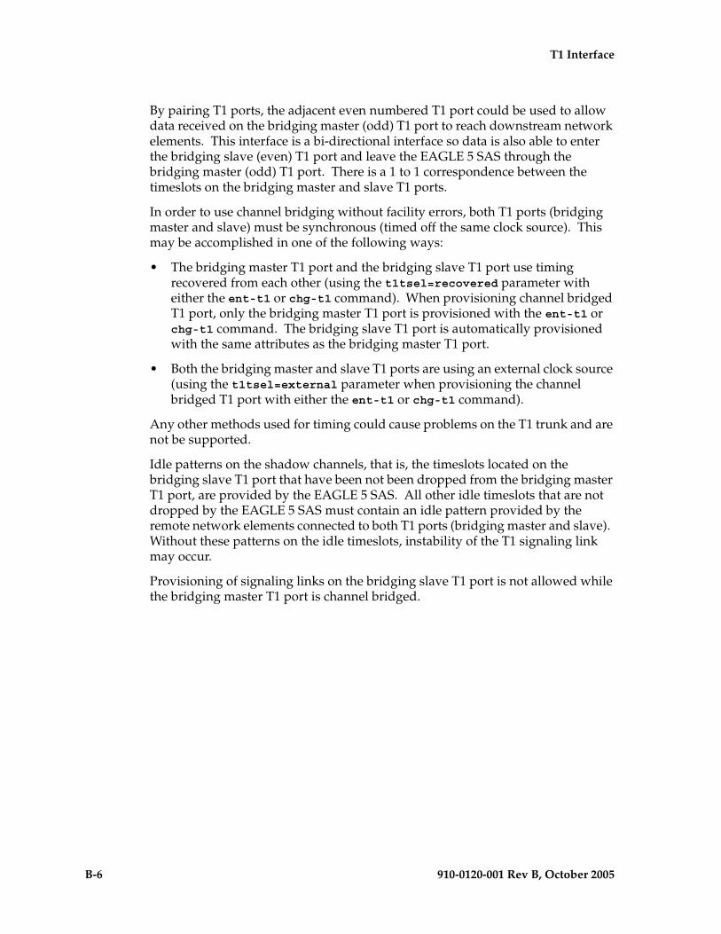
B-6 910-0120-001 Rev B, October 2005
T1 Interface
By pairing T1 ports, the adjacent even numbered T1 port could be used to allow data received on the bridging master (odd) T1 port to reach downstream network elements. This interface is a bi-directional interface so data is also able to enter the bridging slave (even) T1 port and leave the EAGLE 5 SAS through the bridging master (odd) T1 port. There is a 1 to 1 correspondence between the timeslots on the bridging master and slave T1 ports.
In order to use channel bridging without facility errors, both T1 ports (bridging master and slave) must be synchronous (timed off the same clock source). This may be accomplished in one of the following ways:
• The bridging master T1 port and the bridging slave T1 port use timing recovered from each other (using the t1tsel=recovered parameter with either the ent-t1 or chg-t1 command). When provisioning channel bridged T1 port, only the bridging master T1 port is provisioned with the ent-t1 or chg-t1 command. The bridging slave T1 port is automatically provisioned with the same attributes as the bridging master T1 port.
• Both the bridging master and slave T1 ports are using an external clock source (using the t1tsel=external parameter when provisioning the channel bridged T1 port with either the ent-t1 or chg-t1 command).
Any other methods used for timing could cause problems on the T1 trunk and are not be supported.
Idle patterns on the shadow channels, that is, the timeslots located on the bridging slave T1 port that have been not been dropped from the bridging master T1 port, are provided by the EAGLE 5 SAS. All other idle timeslots that are not dropped by the EAGLE 5 SAS must contain an idle pattern provided by the remote network elements connected to both T1 ports (bridging master and slave). Without these patterns on the idle timeslots, instability of the T1 signaling link may occur.
Provisioning of signaling links on the bridging slave T1 port is not allowed while the bridging master T1 port is channel bridged.

T1 Interface
910-0120-001 Rev B, October 2005 B-7
Determining the Configuration
External Interface Descriptions
The T1 backplane provides a method for extending individual T1 channels from the T1-configured cards to any channel-configured cards in use. Note the following issues regarding the T1 backplane:
• Only one T1-configured card may be plugged into each bus on the backplane.
• When installing non-T1 cards on the shelf equipped with the T1 interface backplane, ensure that none of the slots to be used are cabled to the T1 interface backplane. If a non-T1 card is installed in a slot that is connected to the T1 backplane, all T1 cards on that bus may fail.
• Only one T1 card may be connected (via the B port) to each bus of the T1 backplane, and all SS7 links derived from any particular T1 must be processed on the same shelf on which the incoming T1 is terminated.
• Due to cable congestion, Tekelec does not recommend use of the T1 cabling backplane on the control shelf.
• If the control shelf is used, a maximum of 20 T1 interfaces can be utilized in the control shelf.
Descriptions of the T1 hardware and the procedures for installing the T1 hardware are contained in the Hardware Manual - EAGLE 5 SAS and Installation Manual - EAGLE 5 SAS.
The procedure for removing a T1 signaling link is the same as removing an SS7 signaling link, so to remove a T1 signaling link from the database, go to the “Removing an SS7 Signaling Link” procedure on page 3-145.
Possible Configurations
The T1 backplane was designed to allow the maximum number of possible customer setups. It allows the customer to choose between several levels of diversity and convenience. Configurations depend on the number of cards configured as T1 cards versus the number of cards configured as channel cards. The level of diversity required by the customer also affects the configuration requirements. Note that all signals labeled “T1 input” may be one or two T1 ports depending on the cable used.
Support of Two T1 Ports
The E1/T1 MIM will support two T1 ports, which are independently configurable. On a T1 card, T1 port 1 will support channel cards. The second port of that T1 card will only support up to a maximum of eight time slots and will not support channel cards.

B-8 910-0120-001 Rev B, October 2005
T1 Interface
Clocking Options
Each T1 interface must independently operate in one of two clocking modes. When configured as a channel card, a T1 card is required for the channel card’s clocking source.
• Slave Timing - The default receive clock on the LIM-T1 card will be used as the source of the transmit clock.
• Master Timing - The transmit clock of the LIM-T1 card. The Master Timing feature allows a T1 signaling link to take its high-speed clock reference directly from an external high-speed master clock source.
Support of T1 Framing Options
The T1 interfaces independently support either the SF (superframe format) or ESF (extended superframe format) T1 framing options. Selection of these options is made by the framing parameter of either the ent-t1 or chg-t1 commands.
LIM-T1 Card to Channel Card Interface
Whether the T1 card is operating as a T1 card or a channel card, the card will map any eight channels from the T1 interfaces to an HDLC controller (ports A, B, A1, A2, A3, B1, B2, B3). These eight channels could be dropped either both from T1 port 1 or one from T1 port 1 and the other from T1 port 2. When the T1 card is configured as a T1 card, it will support the external T1 cabling backplane interface from T1 port 1 (T1 port 2 will not have this capability) to additional T1 cards, within the same shelf, configured as channel cards. Idle time slots not assigned to a T1 card or a channel card will be filled with a one’s pattern.
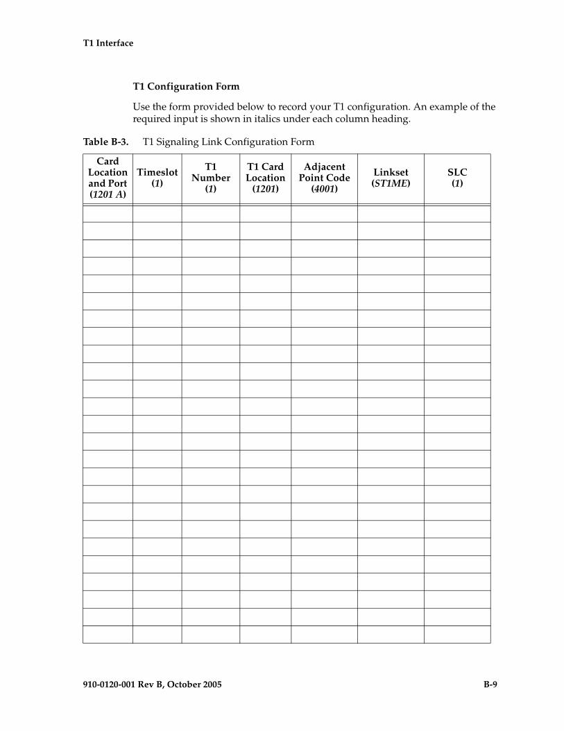
T1 Interface
910-0120-001 Rev B, October 2005 B-9
T1 Configuration Form
Use the form provided below to record your T1 configuration. An example of the required input is shown in italics under each column heading.
Table B-3. T1 Signaling Link Configuration Form
Card Location and Port (1201 A)
Timeslot (1)
T1 Number
(1)
T1 Card Location
(1201)
Adjacent Point Code
(4001)
Linkset (ST1ME)
SLC (1)
B-10 910-0120-001 Rev B, October 2005
T1 Interface
T1 Interface Configuration Procedures
This appendix contains these procedures because they contain information specific to the T1 Interface:
• “Adding a LIM-T1 Card” on page B-11
• “Removing a LIM-T1 Card” on page B-20
• “Adding the T1 Interface Parameters” on page B-24
• “Removing the T1 Interface Parameters” on page B-33
• “Changing the T1 Interface Parameters” on page B-36
• “Adding a T1 Signaling Link” on page B-47
Procedures for configuring the linksets and routes, for removing SS7 signaling links (which includes T1 signaling links), and for configuring the HC MIM temperature alarms are contained in Chapter 3, “SS7 Configuration.” These procedures contain no information that is specific to the T1 interface, therefore, are not included in this appendix.
The procedures contained in this appendix use a variety of commands. If more information on these commands is needed, go to the Commands Manual to find the required information.

T1 Interface
910-0120-001 Rev B, October 2005 B-11
Adding a LIM-T1 Card
The LIM-T1 card is provisioned in the database using the ent-card command. This card can be provisioned as either a T1 card or a channel card. The card being provisioned in the database can be one of these cards shown in Table B-4.
The ent-card command uses these parameters.
:loc – The location of the card being added to the database.
NOTE: The HC MIM can be inserted only in a odd-numbered card location. The HC MIM will not power up if it is inserted in an even-numbered card location. All the T1 backplane cabling should be removed from the B connector for the slot that the HC MIM will occupy.
The HC MIM occupies two card locations, so the even numbered card location adjacent to the odd numbered slot where the HC MIM has been inserted must be empty, as shown in Table B-5. The HC MIM is connected to the network through the odd numbered card slot connector.
:type – The type of card being added to the database. For this procedure, the value of this parameter is limt1 (T1 card) or limch (channel card).
NOTE: The HC MIM cannot be provisioned as a channel card.
:appl – The application software or GPL that is assigned to the card. For this procedure, the value of this parameter is either ccs7itu or ss7ansi.
:force – Allow the LIM to be added to the database even if there are not enough cards running the SCCP GPL (TSM) or running the VSCCP GPL (DSM) in the EAGLE 5 SAS to support the number of LIMs in the EAGLE 5 SAS. This parameter is obsolete and is no longer used.
Table B-4. T1 Card Part Numbers
Card Type Part Number
E1/T1 MIM 870-2198-XX
HC MIM 870-2671-01
Table B-5. HC MIM Card Locations
Location of the HC MIM
Empty Card Location
Location of the HC MIM
Empty Card Location
Slot 01 Slot 02 Slot 11 Slot 12
Slot 03 Slot 04 Slot 13 Slot 14
Slot 05 Slot 06 Slot 15 Slot 16
Slot 07 Slot 08 Slot 17 Slot 18

B-12 910-0120-001 Rev B, October 2005
T1 Interface
The shelf to which the card is to be added, must already be in the database. This can be verified with the rtrv-shlf command. If the shelf is not in the database, see the “Adding a Shelf” procedure in the Database Administration Manual - System Management.
If an HC MIM is being provisioned in this procedure, the FAN feature must be turned on. If the FAN feature is not turned on, the HC MIM will be auto-inhibited when the HC MIM is inserted into the shelf. The status of the FAN feature is shown in the rtrv-feat command output.
If an HC MIM is being provisioned in this procedure, HIPR cards must be installed into card locations 9 and 10 in the shelf that the HC MIM will occupy. If HIPR cards are not installed in the shelf that the HC MIM will occupy, the HC MIM will be auto-inhibited when the HC MIM is inserted into the shelf. Enter the rept-stat-gpl:gpl=hipr command to verify whether or not HIPR cards are installed in the same shelf as the HC MIM being provisioned in this procedure.
The examples in this procedure are used to add the LIM-T1 cards in card locations 1215 and 1216 to the database.
Procedure
1. Display the cards in the EAGLE 5 SAS using the rtrv-card command. This is an example of the possible output.
rlghncxa03w 05-09-28 09:12:36 GMT EAGLE5 34.0.0CARD TYPE APPL LSET NAME LINK SLC LSET NAME LINK SLC1101 TSM SCCP 1102 TSM GLS 1113 GSPM EOAM1114 TDM-A1115 GSPM EOAM1116 TDM-B1117 MDAL1201 LIMV35 CCS7ITU lsne12 A 0 1202 LIMV35 CCS7ITU lsne12 A 1 1203 LIMV35 CCS7ITU lsne13 A 0 1204 LIMV35 CCS7ITU lsne13 A 1 1207 LIMT1 SS7ANSI lsnt265 A 0 1208 LIMCH SS7ANSI lsnt265 A 1 lsnt265 A2 2 1211 LIMT1 CCS7ITU lsne145 A 0 1212 LIMCH CCS7ITU lsne145 A 1 lsne145 A2 2 1305 LIMOCU CCS7ITU sp6 A 0 sp7 B 01306 LIMOCU CCS7ITU nsp3 A 0 nsp4 B 01307 LIMOCU CCS7ITU nsp1 A 0 1308 LIMOCU CCS7ITU nsp1 A 1 1316 ACMENET STPLAN 1314 LIMOCU CCS7ITU sp7 A 1 sp5 B 01317 TSM SCCP
The cards should be distributed throughout the EAGLE 5 SAS for proper power distribution. Refer to the Installation Manual - EAGLE 5 SAS for the shelf power distribution.

T1 Interface
910-0120-001 Rev B, October 2005 B-13
2. Verify that the correct hardware has been installed on the EAGLE 5 SAS to support the LIM-T1 card as shown in the Installation Manual - EAGLE 5 SAS.
3. Physically verify that the E1 card has been installed into the card location that will be specified in step 8. If the E1 card is an HC MIM, make sure the HC MIM is installed according to the card location requirements shown in Table B-5 on page B-11. If a card is installed and provisioned in the even numbered card location adjacent to the desired odd numbered card, either choose another card location to install and provision the HC MIM, or remove the card in the even-numbered card location by performing the appropriate procedure shown in Table B-6.NOTE: Channel cards must be installed in the same shelf as the E1 card that is servicing the timeslots on those channel cards.
Table B-6. Card Removal Procedures
Card Application Procedure
SS7ANSI, ATMANSI, CCS7ITU, ATMITU
“Removing an SS7 LIM” in Chapter 4, “System Configuration Procedures” in the Database Administration Manual - System Management. “Adding a LIM-E1 Card” on page A-14“Removing a LIM-T1 Card” on page B-20
SS7GX25 “Removing an X.25 LIM” in Chapter 2, “X.25 Gateway Configuration,” in the Database Administration Manual - Features
SCCP “Removing an SCCP Card” in Chapter 2, “Global Title Translation (GTT) Configuration,”in the Database Administration Manual - Global Title Translation“Removing an SCCP Card” in the LNP Feature Activation Guide
VSCCP
GLS “Removing a GLS Card” in Chapter 2, “Gateway Screening (GWS) Overview,” in the Database Administration Manual - Gateway Screening
STPLAN, VXWSLAN “Removing an STP LAN Card” in Chapter 3, “STP LAN Configuration,” in the Database Administration Manual - Features
EBDADCM “Removing the DCM Applied to LSMS BLM-Based Operations” in the LNP Feature Activation Guide
EBDABLM “Removing the BLM Applied to LSMS BLM-Based Operations” in the LNP Feature Activation Guide
IPLIM, IPLIMI, SS7IPGW, IPGWI
“Removing an IP Card” in Chapter 3, “IP7 Secure Gateway Configuration Procedures,” in the Database Administration Manual - IP7 Secure Gateway
EROUTE“Removing an STC Card” in Chapter 6, “Eagle Support for Integrated Sentinel Configuration,” in the Database Administration Manual - Features
MCP“Removing an MCPM” in Chapter 4, “System Configuration Procedures” in the Database Administration Manual - System Management.
IPS“Removing an IPSM” in Chapter 4, “System Configuration Procedures” in the Database Administration Manual - System Management.

B-14 910-0120-001 Rev B, October 2005
T1 Interface
NOTE: If the LIM-T1 card being added in this procedure is not an HC MIM, skip steps 4 through 7 and go to step 8.
4. Verify whether or not that the Fan feature is on, by entering the rtrv-feat command. If the global title translation feature is on, the entry FAN = on appears in the rtrv-feat command output.
NOTE: The rtrv-feat command output contains other fields that are not used by this procedure. If you wish to see all the fields displayed by the rtrv-feat command, see the rtrv-feat command description in the Commands Manual.
If the Fan feature is on, skip step 5, and go to step 6.
5. Turn the Fan feature on by entering this command.chg-feat:FAN=on
NOTE: Once the Fan feature is turned on with the chg-feat command, it cannot be turned off.
The Fan feature must be purchased before you turn this feature on with the chg-feat command. If you are not sure if you have purchased the Fan feature, contact your Tekelec Sales Representative or Account Representative.When the chg-feat has successfully completed, this message appears.rlghncxa03w 05-09-28 11:43:04 GMT EAGLE5 34.0.0CHG-FEAT: MASP A - COMPLTD
6. The shelf containing the HC MIM being added in this procedure must have fans installed. Verify whether or not fans are installed on the shelf.
If the fans are installed, go to step 7.If the fans are not installed on the shelf containing the HC MIM, go to the Installation Manual - EAGLE 5 SAS and install the fans. Once the fans have been installed, and tested, go to step 7. The fans must be working properly before an HC MIM can be placed in the EAGLE 5 SAS.
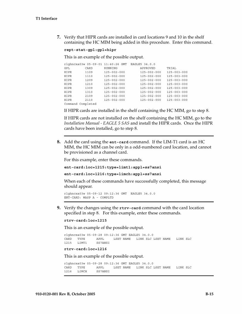
T1 Interface
910-0120-001 Rev B, October 2005 B-15
7. Verify that HIPR cards are installed in card locations 9 and 10 in the shelf containing the HC MIM being added in this procedure. Enter this command.
rept-stat-gpl:gpl=hipr
This is an example of the possible output.
rlghncxa03w 05-09-01 11:40:26 GMT EAGLE5 34.0.0GPL CARD RUNNING APPROVED TRIALHIPR 1109 125-002-000 125-002-000 125-003-000HIPR 1110 125-002-000 125-002-000 125-003-000HIPR 1209 125-002-000 125-002-000 125-003-000HIPR 1210 125-002-000 125-002-000 125-003-000HIPR 1309 125-002-000 125-002-000 125-003-000HIPR 1310 125-002-000 125-002-000 125-003-000HIPR 2109 125-002-000 125-002-000 125-003-000HIPR 2110 125-002-000 125-002-000 125-003-000Command Completed
If HIPR cards are installed in the shelf containing the HC MIM, go to step 8.
If HIPR cards are not installed on the shelf containing the HC MIM, go to the Installation Manual - EAGLE 5 SAS and install the HIPR cards. Once the HIPR cards have been installed, go to step 8.
8. Add the card using the ent-card command. If the LIM-T1 card is an HC MIM, the HC MIM can be only in a odd-numbered card location, and cannot be provisioned as a channel card.
For this example, enter these commands.
ent-card:loc=1215:type=limt1:appl=ss7ansi
ent-card:loc=1216:type=limch:appl=ss7ansi
When each of these commands have successfully completed, this message should appear.
rlghncxa03w 05-09-12 09:12:36 GMT EAGLE5 34.0.0ENT-CARD: MASP A - COMPLTD
9. Verify the changes using the rtrv-card command with the card location specified in step 8. For this example, enter these commands.
rtrv-card:loc=1215
This is an example of the possible output.
rlghncxa03w 05-09-28 09:12:36 GMT EAGLE5 34.0.0CARD TYPE APPL LSET NAME LINK SLC LSET NAME LINK SLC1215 LIMT1 SS7ANSI
rtrv-card:loc=1216
This is an example of the possible output.
rlghncxa03w 05-09-28 09:12:36 GMT EAGLE5 34.0.0CARD TYPE APPL LSET NAME LINK SLC LSET NAME LINK SLC1216 LIMCH SS7ANSI

B-16 910-0120-001 Rev B, October 2005
T1 Interface
10. Backup the new changes using the chg-db:action=backup:dest=fixed command. These messages should appear, the active Maintenance and Administration Subsystem Processor (MASP) appears first.
BACKUP (FIXED) : MASP A - Backup starts on active MASP.BACKUP (FIXED) : MASP A - Backup on active MASP to fixed disk complete.BACKUP (FIXED) : MASP A - Backup starts on standby MASP.BACKUP (FIXED) : MASP A - Backup on standby MASP to fixed disk complete.
Flowchart B-1. Adding a LIM-T1 Card (Sheet 1 of 4)
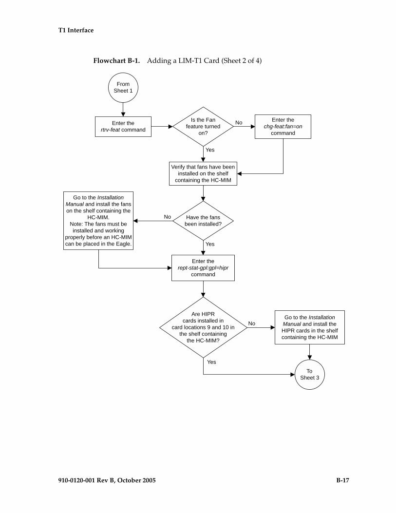
T1 Interface
910-0120-001 Rev B, October 2005 B-17
Flowchart B-1. Adding a LIM-T1 Card (Sheet 2 of 4)

B-18 910-0120-001 Rev B, October 2005
T1 Interface
Flowchart B-1. Adding a LIM-T1 Card (Sheet 3 of 4)

T1 Interface
910-0120-001 Rev B, October 2005 B-19
Flowchart B-1. Adding a LIM-T1 Card (Sheet 4 of 4)

B-20 910-0120-001 Rev B, October 2005
T1 Interface
Removing a LIM-T1 Card
This procedure is used to remove either a T1 card or a channel card from the database using the dlt-card command. The card being removed must exist in the database.
If a T1 card is being removed, then no T1 interfaces can be assigned to the card. This can be verified with the rtrv-t1 command. Go to the “Removing the T1 Interface Parameters” procedure on page B-33 to remove the T1 interfaces assigned to the T1 card being removed from the database.
If only a channel card is being removed from the database, then no SS7 signaling links can be assigned to the card. This can be verified with the rtrv-slk command. Go to the “Removing an SS7 Signaling Link” procedure on page 3-145 to remove the signaling links assigned to the channel card being removed from the database.
CAUTION: If the T1 card or channel card is the last SS7 LIM in service, removing this card from the database will cause SS7 traffic to be lost and isolate the EAGLE 5 SAS from the network.
The examples in this procedure are used to remove the T1 cards in card locations 1207 and 1208.
Procedure
1. Display the cards in the database using the rtrv-card command. This is an example of the possible output.
rlghncxa03w 05-09-28 09:12:36 GMT EAGLE5 34.0.0CARD TYPE APPL LSET NAME LINK SLC LSET NAME LINK SLC1101 TSM SCCP 1102 TSM GLS 1113 GSPM EOAM1114 TDM-A1115 GSPM EOAM1116 TDM-B1117 MDAL1201 LIMV35 CCS7ITU lsne12 A 0 1202 LIMV35 CCS7ITU lsne12 A 1 1203 LIMV35 CCS7ITU lsne13 A 0 1204 LIMV35 CCS7ITU lsne13 A 1 1207 LIMT1 SS7ANSI lsnt265 A 0 1208 LIMCH SS7ANSI lsnt265 A 1 lsnt265 A2 2 1211 LIME1 CCS7ITU lsne145 A 0 1212 LIMCH CCS7ITU lsne145 A 1 lsne145 A2 2 1215 LIMT1 SS7ANSI lsnt145 A 0 1216 LIMCH SS7ANSI lsnt145 A 1 lsnt145 A2 2 1305 LIMOCU CCS7ITU sp6 A 0 sp7 B 01306 LIMOCU CCS7ITU nsp3 A 0 nsp4 B 01307 LIMOCU CCS7ITU nsp1 A 0 1308 LIMOCU CCS7ITU nsp1 A 1 1316 ACMENET STPLAN 1314 LIMOCU CCS7ITU sp7 A 1 sp5 B 01317 TSM SCCP

T1 Interface
910-0120-001 Rev B, October 2005 B-21
NOTE: If a T1 card is being removed from the database, skip this step and go to step 3.
2. Display the signaling links on the channel card you wish to remove by entering the rtrv-slk command, specifying the card location shown in the rtrv-card command output. For this example, enter this command.rtrv-slk:loc=1208
This is an example of the possible output.rlghncxa03w 05-09-19 21:17:04 GMT EAGLE5 34.0.0 L2T PCR PCR T1 T1LOC LINK LSN SLC TYPE SET BPS ECM N1 N2 LOC PORT TS1208 A lsnt265 1 LIMCH 1 56000 BASIC --- ----- 1207 1 61208 A2 lsnt265 2 LIMCH 1 56000 BASIC --- ----- 1207 1 17
Go to the “Removing an SS7 Signaling Link” procedure on page 3-145 to remove the signaling links assigned to the channel card.
NOTE: If only a channel card is being removed from the database, skip this step and go to step 4.
3. Display the T1 interfaces assigned to the T1 card being removed from the database using the rtrv-t1 command with no parameters. This is an example of the possible output.rlghncxa03w 05-09-19 21:17:04 GMT EAGLE5 34.0.0
LOC T1PORT ENCODE T1TSEL FRAMING LL CHANBRDG1207 1 AMI EXTERNAL ESF 50 ------1215 2 B8ZS LINE SF 100 ------
Go to the “Removing the T1 Interface Parameters” procedure on page B-33 to remove the T1 interfaces assigned to the T1 card.
4. Remove the card using the dlt-card command. The dlt-card command has only one parameter, loc, which is the location of the card. For this example, enter these commands.dlt-card:loc=1207
dlt-card:loc=1208
When these commands have successfully completed, this message should appear.rlghncxa03w 05-09-12 09:12:36 GMT EAGLE5 34.0.0DLT-CARD: MASP A - COMPLTD
5. Verify the changes using the rtrv-card command specifying the card that was removed in step 4. For this example, enter these commands.rtrv-card:loc=1207
rtrv-card:loc=1208
When these commands have successfully completed, this message should appear.E2144 Cmd Rej: Location invalid for hardware configuration

B-22 910-0120-001 Rev B, October 2005
T1 Interface
6. Back up the new changes using the chg-db:action=backup:dest=fixed command. These messages should appear, the active Maintenance and Administration Subsystem Processor (MASP) appears first.
BACKUP (FIXED) : MASP A - Backup starts on active MASP.BACKUP (FIXED) : MASP A - Backup on active MASP to fixed disk complete.BACKUP (FIXED) : MASP A - Backup starts on standby MASP.BACKUP (FIXED) : MASP A - Backup on standby MASP to fixed disk complete.
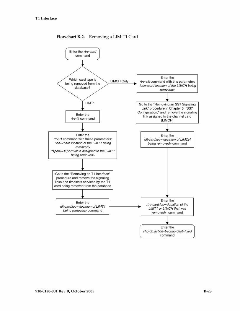
T1 Interface
910-0120-001 Rev B, October 2005 B-23
Flowchart B-2. Removing a LIM-T1 Card
Enter the rtrv-cardcommand
Enter thertrv-t1 command
Which card type isbeing removed from the
database?
Go to the "Removing an SS7 SignalingLink" procedure in Chapter 3, "SS7
Configuration," and remove the signalinglink assigned to the channel card
(LIMCH)
LIMCH Only
LIMT1
Enter thertrv-t1 command with these parameters::loc=<card location of the LIMT1 being
removed>:t1port=<t1port value assigned to the LIMT1
being removed>
Go to the "Removing an T1 Interface"procedure and remove the signaling
links and timeslots serviced by the T1card being removed from the database
Enter thedlt-card:loc=<location of LIMCH
being removed> command
Enter thechg-db:action=backup:dest=fixed
command
Enter thertrv-card:loc=<location of the
LIMT1 or LIMCH that wasremoved> command
Enter thedlt-card:loc=<location of LIMT1
being removed> command
Enter thertrv-slk command with this parameter:
:loc=<card location of the LIMCH beingremoved>

B-24 910-0120-001 Rev B, October 2005
T1 Interface
Adding the T1 Interface Parameters
The T1 interface parameters are provisioned in the database using the ent-t1 command using these parameters.
:loc – The location of the T1 card (card type limt1) that is servicing the T1 signaling link. The location of a channel card (card type limch) cannot be specified for this parameter.
:t1port – The T1 port on the T1 card used to service the T1 signaling link. The t1port value cannot already be assigned to the T1 card specified by the loc parameter.
:encode – Specifies the type of encoding or decoding that is used on the T1 signaling link, either B8ZS or AMI. The default value is B8ZS encoding (encode=b8zs).
:t1tsel – The timing source for the T1 signaling link, master (external) or slave (line) or recovered. The default value is slave timing (t1tsel=line).
The recovered timing source can be used only with the chanbrdg=on parameter and uses the even numbered member of the bridged-pair as a clock source, ensuring that both T1 ports are using the same clock for line stability.
NOTE: To use an external high-speed master clock source other than RS-422, TDMs 870-0774-15 or later must be installed in card locations 1114 and 1116, and the TDM Global Timing Interface options must be configured. For more information, see the “Configuring the Options for the TDM Global Timing Interface” procedure on page 3-263.
:framing – Specifies the framing format to be used on the TI signaling link, either sf or esf. The default value is sf (framing=sf).
:ll – The length of the cable, in feet, used for the T1 signaling link. The value of the ll parameter is from 0 to 655. The default value for this parameter is 133.
:chanbrdg – Specifies whether or not the odd numbered T1 port specified in this procedure is channel bridged to its adjacent even numbered T1 port. Table B-7 on page B-24 shows the T1 ports that can be specified with the chanbrdg=on parameter and the even-numbered T1 ports that are bridged to the odd numbered T1 port.
Table B-7. Channel Bridging Ports
Odd Numbered T1 Port
Even Numbered Bridged T1 Port
1 2
3 4
5 6
7 8

T1 Interface
910-0120-001 Rev B, October 2005 B-25
:force=yes – required when the even numbered T1 port being channel bridged is provisioned in the database before this procedure is performed.
The T1 card specified in this procedure must be in the database. This can be verified with the rtrv-card command.
Procedure
1. Display the cards in the EAGLE 5 SAS using the rtrv-card command. This is an example of the possible output.
rlghncxa03w 05-09-28 09:12:36 GMT EAGLE5 34.0.0CARD TYPE APPL LSET NAME LINK SLC LSET NAME LINK SLC1101 TSM SCCP 1102 TSM GLS 1113 GSPM EOAM1114 TDM-A1115 GSPM EOAM1116 TDM-B1117 MDAL1201 LIMV35 CCS7ITU lsne12 A 0 1202 LIMV35 CCS7ITU lsne12 A 1 1203 LIMV35 CCS7ITU lsne13 A 0 1204 LIMV35 CCS7ITU lsne13 A 1 1207 LIMT1 SS7ANSI lsnt265 A 0 1208 LIMCH SS7ANSI lsnt265 A 1 lsnt265 A2 2 1211 LIME1 CCS7ITU lsne145 A 0 1212 LIMCH CCS7ITU lsne145 A 1 lsne145 A2 2 1215 LIMT1 SS7ANSI 1216 LIMCH SS7ANSI 1305 LIMOCU CCS7ITU sp6 A 0 sp7 B 01306 LIMOCU CCS7ITU nsp3 A 0 nsp4 B 01307 LIMOCU CCS7ITU nsp1 A 0 1308 LIMOCU CCS7ITU nsp1 A 1 1316 ACMENET STPLAN 1314 LIMOCU CCS7ITU sp7 A 1 sp5 B 01317 TSM SCCP
2. Display the existing T1 interfaces in the database using the rtrv-t1 command with no parameters. This is an example of the possible output.
rlghncxa03w 05-09-19 21:17:04 GMT EAGLE5 34.0.0
LOC T1PORT ENCODE T1TSEL FRAMING LL CHANBRDG1207 1 AMI EXTERNAL ESF 50 ------

B-26 910-0120-001 Rev B, October 2005
T1 Interface
NOTE: If the rtrv-t1 output in step 2 shows that the T1 card has T1 ports 3, 4, 5, 6, 7, or 8 assigned to it, or that T1 ports on the T1 card are channel bridged, skip this step and go to step 4.
3. Verify whether or not the T1 card is an HC MIM. The HC MIM has part number 870-2671-01 assigned to it.
If the T1 card is an HC MIM, go to step 4.
If the T1 card is not an HC MIM, skip step 4, and go to step 5.
NOTE: If the T1 port being added in this procedure is not being channel bridged, skip step 4, and go to 5.
4. Display the T1 signaling links in the EAGLE 5 SAS by entering this command.
rtrv-slk:class=t1
This is an example of the possible output.
rlghncxa03w 05-09-19 21:17:04 GMT EAGLE5 34.0.0
L2T PCR PCR T1 T1LOC LINK LSN SLC TYPE SET BPS ECM N1 N2 LOC PORT TS1207 A lsnt256 0 LIMT1 1 56000 BASIC --- ----- 1207 2 21208 A lsnt256 1 LIMCH 1 56000 BASIC --- ----- 1207 1 41208 A2 lsnt256 2 LIMCH 1 56000 BASIC --- ----- 1207 1 6
If an even numbered T1 port is to be channel bridged, and that T1 port is assigned to signaling links, these signaling links must be removed before the T1 port can be channel bridged. Perform the “Removing an SS7 Signaling Link” procedure on page 3-145 and remove these signaling links. After the signaling links have been removed, go to step 5.
If the even numbered T1 port to be channel bridged is not assigned to signaling links, go to step 5.
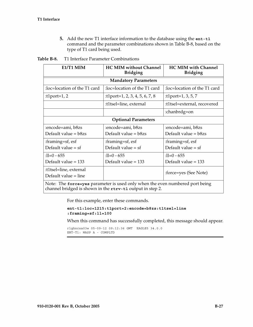
T1 Interface
910-0120-001 Rev B, October 2005 B-27
5. Add the new T1 interface information to the database using the ent-t1 command and the parameter combinations shown in Table B-8, based on the type of T1 card being used.
For this example, enter these commands.
ent-t1:loc=1215:t1port=2:encode=b8zs:t1tsel=line:framing=sf:ll=100
When this command has successfully completed, this message should appear.
rlghncxa03w 05-09-12 09:12:36 GMT EAGLE5 34.0.0ENT-T1: MASP A - COMPLTD
Table B-8. T1 Interface Parameter Combinations
E1/T1 MIM HC MIM without Channel Bridging
HC MIM with Channel Bridging
Mandatory Parameters
:loc=location of the T1 card :loc=location of the T1 card :loc=location of the T1 card
:t1port=1, 2 :t1port=1, 2, 3, 4, 5, 6, 7, 8 :t1port=1, 3, 5, 7
:t1tsel=line, external :t1tsel=external, recovered
:chanbrdg=on
Optional Parameters
:encode=ami, b8zsDefault value = b8zs
:encode=ami, b8zsDefault value = b8zs
:encode=ami, b8zsDefault value = b8zs
:framing=sf, esfDefault value = sf
:framing=sf, esfDefault value = sf
:framing=sf, esfDefault value = sf
:ll=0 - 655Default value = 133
:ll=0 - 655Default value = 133
:ll=0 - 655Default value = 133
:t1tsel=line, external Default value = line
:force=yes (See Note)
Note: The force=yes parameter is used only when the even numbered port being channel bridged is shown in the rtrv-t1 output in step 2.
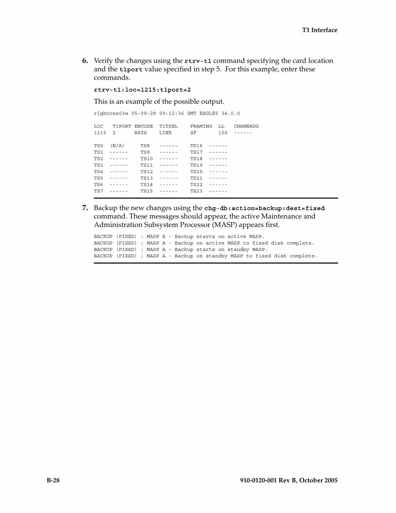
B-28 910-0120-001 Rev B, October 2005
T1 Interface
6. Verify the changes using the rtrv-t1 command specifying the card location and the t1port value specified in step 5. For this example, enter these commands.
rtrv-t1:loc=1215:t1port=2
This is an example of the possible output.
rlghncxa03w 05-09-28 09:12:36 GMT EAGLE5 34.0.0
LOC T1PORT ENCODE T1TSEL FRAMING LL CHANBRDG1215 2 B8ZS LINE SF 100 ------
TS0 (N/A) TS8 ------ TS16 ------TS1 ------ TS9 ------ TS17 ------TS2 ------ TS10 ------ TS18 ------TS3 ------ TS11 ------ TS19 ------TS4 ------ TS12 ------ TS20 ------TS5 ------ TS13 ------ TS21 ------TS6 ------ TS14 ------ TS22 ------TS7 ------ TS15 ------ TS23 ------
7. Backup the new changes using the chg-db:action=backup:dest=fixed command. These messages should appear, the active Maintenance and Administration Subsystem Processor (MASP) appears first.
BACKUP (FIXED) : MASP A - Backup starts on active MASP.BACKUP (FIXED) : MASP A - Backup on active MASP to fixed disk complete.BACKUP (FIXED) : MASP A - Backup starts on standby MASP.BACKUP (FIXED) : MASP A - Backup on standby MASP to fixed disk complete.
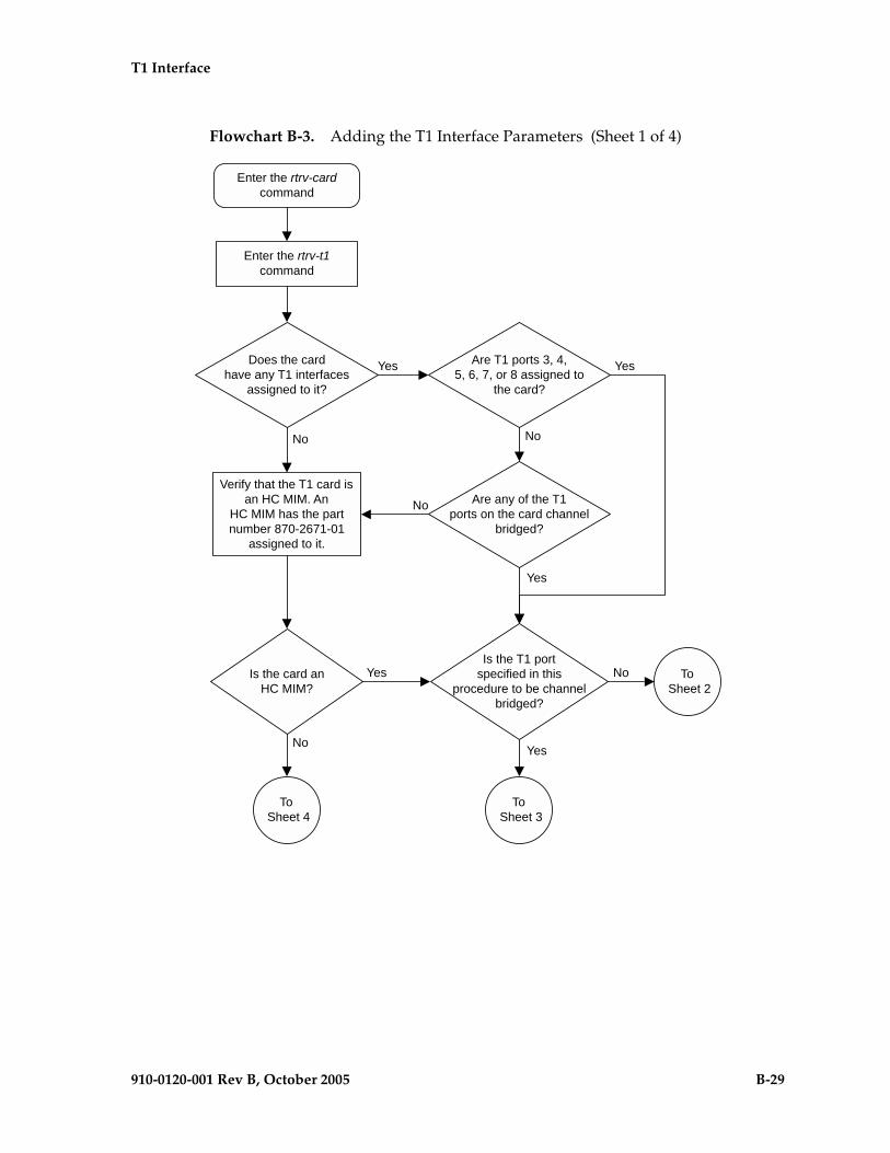
T1 Interface
910-0120-001 Rev B, October 2005 B-29
Flowchart B-3. Adding the T1 Interface Parameters (Sheet 1 of 4)
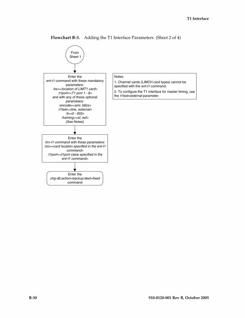
B-30 910-0120-001 Rev B, October 2005
T1 Interface
Flowchart B-3. Adding the T1 Interface Parameters (Sheet 2 of 4)
Enter theent-t1 command with these mandatory
parameters::loc=<location of LIMT1 card>
:t1port=<T1 port 1 - 8>and with any of these optional
parameters::encode=<ami, b8zs>:t1tsel=<line, external>
:ll=<0 - 655>:framing=<sf, esf>
(See Notes)
Enter thechg-db:action=backup:dest=fixed
command
Enter thertrv-t1 command with these parameters::loc=<card location specified in the ent-t1
command>:t1port=<t1port value specified in the
ent-t1 command>
From Sheet 1
Notes:
1. Channel cards (LIMCH card types) cannot bespecified with the ent-t1 command.
2. To configure the T1 interface for master timing, usethe t1tsel=external parameter.
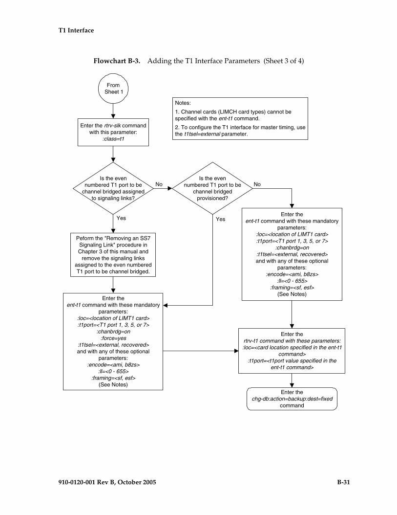
T1 Interface
910-0120-001 Rev B, October 2005 B-31
Flowchart B-3. Adding the T1 Interface Parameters (Sheet 3 of 4)
Enter thechg-db:action=backup:dest=fixed
command
Enter thertrv-t1 command with these parameters::loc=<card location specified in the ent-t1
command>:t1port=<t1port value specified in the
ent-t1 command>
From Sheet 1
Enter the rtrv-slk commandwith this parameter:
:class=t1
Is the evennumbered T1 port to be
channel bridged assignedto signaling links?
No
Yes
Is the evennumbered T1 port to be
channel bridgedprovisioned?
No
Yes
Peform the "Removing an SS7Signaling Link" procedure inChapter 3 of this manual and
remove the signaling linksassigned to the even numberedT1 port to be channel bridged.
Enter theent-t1 command with these mandatory
parameters::loc=<location of LIMT1 card>:t1port=<T1 port 1, 3, 5, or 7>
:chanbrdg=on:t1tsel=<external, recovered>and with any of these optional
parameters::encode=<ami, b8zs>
:ll=<0 - 655>:framing=<sf, esf>
(See Notes)Enter the
ent-t1 command with these mandatoryparameters:
:loc=<location of LIMT1 card>:t1port=<T1 port 1, 3, 5, or 7>
:chanbrdg=on:force=yes
:t1tsel=<external, recovered>and with any of these optional
parameters::encode=<ami, b8zs>
:ll=<0 - 655>:framing=<sf, esf>
(See Notes)
Notes:
1. Channel cards (LIMCH card types) cannot bespecified with the ent-t1 command.
2. To configure the T1 interface for master timing, usethe t1tsel=external parameter.

B-32 910-0120-001 Rev B, October 2005
T1 Interface
Flowchart B-3. Adding the T1 Interface Parameters (Sheet 4 of 4)
Enter theent-t1 command with these mandatory
parameters::loc=<location of LIMT1 card>
:t1port=<T1 ports 1 or 2>and with any of these optional
parameters::encode=<ami, b8zs>:t1tsel=<line, external>
:ll=<0 - 655>:framing=<sf, esf>
(See Notes)
Notes:
1. Channel cards (LIMCH card types) cannot bespecified with the ent-t1 command.
2. To configure the T1 interface for master timing, usethe t1tsel=external parameter.
Enter thechg-db:action=backup:dest=fixed
command
Enter thertrv-t1 command with these parameters::loc=<card location specified in the ent-t1
command>:t1port=<t1port value specified in the
ent-t1 command>
From Sheet 1

T1 Interface
910-0120-001 Rev B, October 2005 B-33
Removing the T1 Interface Parameters
This procedure is used to remove a T1 interface from the database using the dlt-t1 command using these parameters.
:loc – The location of the T1 card (card type limt1) containing the T1 interface being removed.
:t1port – The T1 port on the T1 card containing the T1 interface being removed.
The T1 interface to be removed must exist in the database. This can be verified in step 1.
To remove the T1 interface information contained on a T1 card, all signaling links serviced by that T1 card must be removed from the database. This can be verified with the rtrv-t1 command, specifying the card location and T1PORT on the T1 card, and the rtrv-slk command, specifying the location of any cards (T1 or channel cards) shown in the rtrv-t1 output. If there are any signaling links being serviced by the T1 card, go to the “Removing an SS7 Signaling Link” procedure on page 3-145 and remove these signaling links.
Even numbered T1 ports cannot be removed if the even numbered T1 port is channel bridged. Remove the corresponding odd numbered T1 port (see Table B-7 on page B-24) to remove the even numbered channel bridged T1 port.
Procedure
1. Display the existing T1 interfaces in the database using the rtrv-t1 command with no parameters. This is an example of the possible output.
rlghncxa03w 05-09-19 21:17:04 GMT EAGLE5 34.0.0
LOC T1PORT ENCODE T1TSEL FRAMING LL CHANBRDG1207 1 AMI EXTERNAL ESF 50 ------1215 2 B8ZS LINE SF 100 ------
If the T1 port being removed is an even numbered T1 port and is channel bridged, select the corresponding odd numbered T1 port to remove (see Table B-7 on page B-24) and go to step 2.
If the even numbered T1 port is not channel bridged, it can be removed with the dlt-t1 command. go to step 2.

B-34 910-0120-001 Rev B, October 2005
T1 Interface
2. Display the timeslots that are serviced by the T1 card containing the T1 interface information to be removed using the rtrv-t1 command specifying the card location and the t1port value from step 1. For this example, enter this command.
rtrv-t1:loc=1207:t1port=1
This is an example of the possible output.
rlghncxa03w 05-09-28 09:12:36 GMT EAGLE5 34.0.0
LOC T1PORT ENCODE T1TSEL FRAMING LL CHANBRDG1207 1 AMI EXTERNAL ESF 50 ------
TS0 (N/A) TS8 ------ TS16 ------TS1 ------ TS9 ------ TS17 1208,A2TS2 1207,A TS10 ------ TS18 ------TS3 ------ TS11 ------ TS19 ------TS4 ------ TS12 ------ TS20 ------TS5 ------ TS13 ------ TS21 ------TS6 1208,A TS14 ------ TS22 ------TS7 ------ TS15 ------ TS23 ------
If this step shows any timeslots that are serviced by the T1 card, go to the “Removing an SS7 Signaling Link” procedure on page 3-145 and remove the timeslots and signaling links serviced by the T1 card.
3. Remove the T1 interface information to the database using the dlt-t1 command specifying the card location of the T1 card and the T1 port on that card. For this example, enter these commands.
dlt-t1:loc=1207:t1port=1
When this command has successfully completed, this message should appear.
rlghncxa03w 05-09-12 09:12:36 GMT EAGLE5 34.0.0DLT-T1: MASP A - COMPLTD
4. Verify the changes using the rtrv-t1 command with no parameters. This is an example of the possible output.
rlghncxa03w 05-09-19 21:17:04 GMT EAGLE5 34.0.0
LOC T1PORT ENCODE T1TSEL FRAMING LL CHANBRDG1215 2 B8ZS LINE SF 100 ------
5. Backup the new changes using the chg-db:action=backup:dest=fixed command. These messages should appear, the active Maintenance and Administration Subsystem Processor (MASP) appears first.
BACKUP (FIXED) : MASP A - Backup starts on active MASP.BACKUP (FIXED) : MASP A - Backup on active MASP to fixed disk complete.BACKUP (FIXED) : MASP A - Backup starts on standby MASP.BACKUP (FIXED) : MASP A - Backup on standby MASP to fixed disk complete.

T1 Interface
910-0120-001 Rev B, October 2005 B-35
Flowchart B-4. Removing the T1 Interface Parameters
Enter the rtrv-t1command
Enter thedlt-t1 command with these parameters:
:loc=<location of LIMT1 card>:t1port=<T1 port on T1 Card>
Enter thechg-db:action=backup:dest=fixed
command
Does the rtrv-t1output show any timeslotsthat are serviced by this T1
port?
Yes
No
Go to the "Removing an SS7Signaling Link" procedure in
Chapter 3, "SS7 Configuration,"and remove the signaling links andtimeslots serviced by the T1 port
Enter the rtrv-t1 command with theseparameters:
:loc=<T1 card location>t1port=<T1 port being removed>
Enter the rtrv-t1 command command withthese parameters:
:loc=<card location used in the dlt-t1command>
:t1port=<T1 port used in the dlt-t1command>
Is the T1 Port aneven numbered port?
Is the evennumbered T1 port channel
bridged to its masterport?
Even numbered T1 ports cannot bespecified in this procedure. The master
T1 port (the odd numbered T1 port) mustbe removed to remove the even
numbered T1 port. Perform the dlt-t1command specifying the master T1 port.
YesYes
NoNo

B-36 910-0120-001 Rev B, October 2005
T1 Interface
Changing the T1 Interface Parameters
This procedure is used to change the existing T1 interface parameters using the chg-t1 command using these parameters.
:loc – The location of the T1 card (card type limt1) that is servicing the T1 signaling link. The location of a channel card (card type limch) cannot be specified for this parameter.
:t1port – The T1 port on the T1 card used to service the T1 signaling link. The t1port value cannot already be assigned to the T1 card specified by the loc parameter.
:encode – Specifies the type of encoding or decoding that is used on the T1 signaling link, either B8ZS or AMI.
:t1tsel – The timing source for the T1 signaling link, master (external) or slave (line), or recovered.
The recovered timing source can be used only with the chanbrdg=on parameter and uses the even numbered member of the bridged-pair as a clock source, ensuring that both T1 ports are using the same clock for line stability.
NOTE: To use an external high-speed master clock source other than RS-422, TDMs 870-0774-15 or later must be installed in card locations 1114 and 1116, and the TDM Global Timing Interface options must be configured. For more information, see the “Configuring the Options for the TDM Global Timing Interface” procedure on page 3-263.
:framing – Specifies the framing format to be used on the TI signaling link, either sf or esf.
:ll – The length of the cable, in feet, used for the T1 signaling link. The value of the ll parameter is from 0 to 655.
:chanbrdg – Specifies whether or not the odd numbered T1 port specified in this procedure is channel bridged to its adjacent even numbered T1 port. Table B-9 on page B-36 shows the T1 ports that can be specified with the chanbrdg=on parameter and the even-numbered T1 ports that are bridged to the odd numbered T1 port.
Table B-9. Channel Bridging Ports
Odd Numbered T1 Port
Even Numbered Bridged T1 Port
1 2
3 4
5 6
7 8

T1 Interface
910-0120-001 Rev B, October 2005 B-37
:force=yes – required when the even numbered T1 port being channel bridged is provisioned in the database before this procedure is performed.
The T1 card specified in this procedure must be in the database. This can be verified with the rtrv-card command.
The signaling links serviced by the T1 card must be taken out of service before any changes can be made to the T1 interface parameters.
Procedure
1. Display the existing T1 interfaces in the database using the rtrv-t1 command with no parameters. This is an example of the possible output.rlghncxa03w 05-09-19 21:17:04 GMT EAGLE5 34.0.0
LOC T1PORT ENCODE T1TSEL FRAMING LL CHANBRDG1207 1 AMI EXTERNAL ESF 50 ------1215 2 B8ZS LINE SF 100 ------
2. Display the timeslots that are serviced by the T1 card containing the T1 interface information to be changed using the rtrv-t1 command specifying the card location and the t1port value from step 1. For this example, enter this command.
rtrv-t1:loc=1215:t1port=2
This is an example of the possible output.rlghncxa03w 05-09-28 09:12:36 GMT EAGLE5 34.0.0
LOC T1PORT ENCODE T1TSEL FRAMING LL CHANBRDG1215 2 B8ZS LINE SF 50 ------
TS0 (N/A) TS8 ------ TS16 ------TS1 ------ TS9 ------ TS17 ------TS2 ------ TS10 1215,A TS18 ------TS3 ------ TS11 ------ TS19 ------TS4 ------ TS12 ------ TS20 1216,A2TS5 ------ TS13 ------ TS21 ------TS6 ------ TS14 1216,A TS22 ------TS7 ------ TS15 ------ TS23 ------
3. Check the status of the signaling links shown in step 2 using the rept-stat-slk command with the card location and signaling link. For this example, enter these commands.rept-stat-slk:loc=1215:link=a
This is an example of the possible output.rlghncxa03w 05-09-23 13:06:25 GMT EAGLE5 34.0.0SLK LSN CLLI PST SST AST1215,A lsnt145 ----------- IS-NR Avail ---- ALARM STATUS = No Alarms UNAVAIL REASON = -- T1 status = 1215, RCVRY-T1F:FAC-T1 Port 2 available

B-38 910-0120-001 Rev B, October 2005
T1 Interface
rept-stat-slk:loc=1216:link=a
This is an example of the possible output.rlghncxa03w 05-09-23 13:06:25 GMT EAGLE5 34.0.0SLK LSN CLLI PST SST AST1216,A lsnt145 ----------- IS-NR Avail ---- ALARM STATUS = No Alarms UNAVAIL REASON = -- T1 status = 1215, RCVRY-T1F:FAC-T1 Port 1 available
rept-stat-slk:loc=1216:link=a2
This is an example of the possible output.rlghncxa03w 05-09-23 13:06:25 GMT EAGLE5 34.0.0SLK LSN CLLI PST SST AST1216,A2 lsnt145 ----------- IS-NR Avail ---- ALARM STATUS = No Alarms UNAVAIL REASON = -- T1 status = 1215, RCVRY-T1F:FAC-T1 Port 1 available
4. Deactivate the signaling links shown in step 3 using the dact-slk command. For this example, enter these commands.
dact-slk:loc=1215:link=a
dact-slk:loc=1216:link=a
dact-slk:loc=1216:link=a2
When each of these commands have successfully completed, this message should appear.
rlghncxa03w 05-09-07 08:41:12 GMT EAGLE5 34.0.0Deactivate Link message sent to card
NOTE: If the chanbrdg value will be changed to off, skip steps 5 and 6, and go to step 7.
5. If T1 ports 3, 4, 5, 6, 7, or 8 are not assigned to the T1 card, verify that the card is an HC MIM. Only T1 ports assigned to HC MIM cards can be channel bridged. If the T1 card is an HC MIM, go to step 6.
If the T1 card is not an HC MIM, the T1 port cannot be channel bridged. Go back to step 1 and perform this procedure again. If there are no HC MIMs in the database, go to step 7 and change other parameters for this T1 port.
If T1 ports 3, 4, 5, 6, 7, or 8 are assigned to the T1 card, the T1 card is an HC MIM. Go to step 6.

T1 Interface
910-0120-001 Rev B, October 2005 B-39
NOTE: If the adjacent T1 port (see Table B-9 on page B-36) is not shown in the rtrv-t1 output in step 1, or if the chanbrdg value is not being changed, skip this step and go to step 7.
6. Display the T1 signaling links in the database by entering this command.
rtrv-slk:class=t1
This is an example of the possible output.
rlghncxa03w 05-09-19 21:17:04 GMT EAGLE5 34.0.0
L2T PCR PCR T1 T1LOC LINK LSN SLC TYPE SET BPS ECM N1 N2 LOC PORT TS1207 A lsnt256 0 LIMT1 1 56000 BASIC --- ----- 1207 2 21208 A lsnt256 1 LIMCH 1 56000 BASIC --- ----- 1207 1 41208 A2 lsnt256 2 LIMCH 1 56000 BASIC --- ----- 1207 1 6
If an even numbered T1 port is to be channel bridged, and that T1 port is assigned to signaling links, these signaling links must be removed before the T1 port can be channel bridged. Perform the “Removing an SS7 Signaling Link” procedure on page 3-145 and remove these signaling links. After the signaling links have been removed, go to step 7.
If the even numbered T1 port to be channel bridged is not assigned to signaling links, go to step 7.
7. Change the T1 interface information using the chg-t1 command and the parameter combinations shown in Table B-10, based on the type of T1 card being used.
Table B-10. T1 Interface Parameter Combinations
E1/T1 MIM HC MIM
Mandatory Parameters
:loc=location of the T1 card :loc=location of the T1 card :loc=location of the T1 card
:t1port=T1 port being changed, either 1 or 2
:t1port=T1 port being changed, either 1, 2, 3, 4, 5, 6, 7, or 8 1
:t1port=T1 port being changed, either 1, 3, 5, or 7
Optional Parameters
:encode=ami, b8zs :encode=ami, b8zs :encode=ami, b8zs
:ll=0 - 655 :ll=0 - 655 :ll=0 - 655
:framing=sf, esf :framing=sf, esf :framing=sf, esf
:t1tsel=line, external :t1tsel=line, external :t1tsel=external, recovered
:chanbrdg=off :chanbrdg=on
:force=yes 2

B-40 910-0120-001 Rev B, October 2005
T1 Interface
For this example, enter this command.
chg-t1:loc=1215:t1port=2:encode=ami:framing=esf
When this command has successfully completed, this message should appear.
rlghncxa03w 05-09-12 09:12:36 GMT EAGLE5 34.0.0ENT-T1: MASP A - COMPLTD
8. Verify the changes using the rtrv-t1 command specifying the card location and the t1port value specified in step 7. For this example, enter these commands.
rtrv-t1:loc=1215:t1port=2
This is an example of the possible output.
rlghncxa03w 05-09-28 09:12:36 GMT EAGLE5 34.0.0
LOC T1PORT ENCODE T1TSEL FRAMING LL CHANBRDG1215 2 AMI LINE ESF 100 ------
TS0 (N/A) TS8 ------ TS16 ------TS1 ------ TS9 ------ TS17 ------TS2 ------ TS10 1215,A TS18 ------TS3 ------ TS11 ------ TS19 ------TS4 ------ TS12 ------ TS20 1216,A2TS5 ------ TS13 ------ TS21 ------TS6 ------ TS14 1216,A TS22 ------TS7 ------ TS15 ------ TS23 ------
NOTE: If the signaling links were not deactivated in step 4, skip this step and go to step 10.
9. Activate the signaling links that were deactivated in step 4 using the act-slk command. For this example, enter these commands.
act-slk:loc=1215:link=a
act-slk:loc=1216:link=a
act-slk:loc=1216:link=a2
When each of these commands have successfully completed, this message should appear.
rlghncxa03w 05-09-07 08:41:12 GMT EAGLE5 34.0.0Activate Link message sent to card
Notes: 1. If the current T1 port is channel bridged, the t1port value can either 1, 3, 5, or 7.2. The force=yes parameter is used only when the even numbered port being channel bridged is shown in the rtrv-t1 output in step 1.
Table B-10. T1 Interface Parameter Combinations
E1/T1 MIM HC MIM

T1 Interface
910-0120-001 Rev B, October 2005 B-41
10. Backup the new changes using the chg-db:action=backup:dest=fixed command. These messages should appear, the active Maintenance and Administration Subsystem Processor (MASP) appears first.
BACKUP (FIXED) : MASP A - Backup starts on active MASP.BACKUP (FIXED) : MASP A - Backup on active MASP to fixed disk complete.BACKUP (FIXED) : MASP A - Backup starts on standby MASP.BACKUP (FIXED) : MASP A - Backup on standby MASP to fixed disk complete.
Flowchart B-5. Changing the T1 Interface Parameters (Sheet 1 of 6)
Enter the rtrv-t1command
Enter therept-stat-slk:loc<LIMT1 card location>
:link=<T1 signaling link>command
Are the signaling linksserviced by the T1 port out of
service?
Enter thedact-slk:loc<LIMT1
card location>:link=<T1 signaling
link>command
Have all the signalinglinks serviced by the T1 portbeen taken out of service?
YesNo
To Sheet 5
Yes
No
Enter thertrv-t1:loc<LIMT1 card location>
:t1port=<T1 port on T1 card>command
To Sheet 2
Is the chanbrdg(channel bridging) value to
be changed?
No
Yes

B-42 910-0120-001 Rev B, October 2005
T1 Interface
Flowchart B-5. Changing the T1 Interface Parameters (Sheet 2 of 6)

T1 Interface
910-0120-001 Rev B, October 2005 B-43
Flowchart B-5. Changing the T1 Interface Parameters (Sheet 3 of 6)
From Sheet 2
Enter thechg-t1 command with these mandatory
parameters::loc=<location of LIMT1 card>
:t1port=<T1 port being changed,either 1, 3, 5, or 7>
:chanbrdg=offand with any of these optional
parameters::encode=<ami, z8bs>:t1tsel=<line, external>
:ll=<0 - 655>:framing=<sf, esf>
(See Notes)Notes:
1. When the chanbrdg value is changedto off, the even-numbered T1 port thatwas channel bridged to the T1 portspecified in this step will be removed.
2. If the t1tsel value is recovered, thet1tsel value must be changed to eitherline or external.
Enter thechg-db:action=backup:dest=fixed
command
Enter thertrv-t1 command with these parameters:
:loc=<card location specified in the chg-t1command>
:t1port=<t1port value specified in thechg-t1 command>

B-44 910-0120-001 Rev B, October 2005
T1 Interface
Flowchart B-5. Changing the T1 Interface Parameters (Sheet 4 of 6)
Perform the "Removing an SS7Signaling Link" procedure in Chapter 3
of this manual and remove all thesignaling links assigned to the adjacent
T1 port.
Is the adjacent T1port provisioned?
No
Yes
From Sheets 1
or 3
Is the adjacent T1 portnumber assigned to any
signaling links?
Enter thechg-t1 command with these mandatory parameters:
:loc=<location of LIMT1 card>:t1port=<T1 port being changed, either 1, 3, 5,
or 7>:chanbrdg=on
and with any of these optional parameters::force=yes
:t1tsel=<external, recovered>:encode=<ami, z8bs>
:ll=<0 - 655>:framing=<sf, esf>
Notes:
1. If the adjacent even-numbered T1 port is notprovisioned in the database before this step isperformed, this T1 port will be added when this stepis performed.
2. If the adjacent even-numbered T1 port isprovisioned in the database before this step isperformed, the force=yes parameter must bespecified with the chg-t1 command.
Yes
No
To Sheet 6
Enter thertrv-slk command with this parameter:
:class=t1
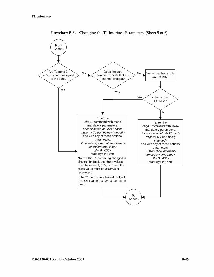
T1 Interface
910-0120-001 Rev B, October 2005 B-45
Flowchart B-5. Changing the T1 Interface Parameters (Sheet 5 of 6)

B-46 910-0120-001 Rev B, October 2005
T1 Interface
Flowchart B-5. Changing the T1 Interface Parameters (Sheet 6 of 6)
Enter thechg-db:action=backup:dest=fixed
command
Enter thertrv-t1 command with these parameters:
:loc=<card location specified in the chg-t1command>
:t1port=<t1port value specified in thechg-t1 command>
Have all the signalinglinks serviced by the T1 card
been activated?
No
Yes
From Sheets 4
or 5
Enter theact-slk:loc<LIMT1 card location>
:link=<T1 signaling link>command
Were any signaling linksserviced by the T1 card
deactivated?
Yes
No

T1 Interface
910-0120-001 Rev B, October 2005 B-47
Adding a T1 Signaling Link
This procedure is used to add a T1 signaling link to the database using the ent-slk command and these parameters.
:loc – The card location of the card that the T1 signaling link will be assigned to.
:link – The signaling link on the card specified in the loc parameter.
:lsn – The name of the linkset that will contain the signaling link.
:slc – The signaling link code. The SLC must be unique within the linkset. It must be the same at both the EAGLE 5 SAS location and the distant node.
:bps – The transmission rate for the link in bits per second.
:ecm – Error correction method, either basic or pcr. The default value for this parameter is basic.
:pcrn1 – The threshold of the number of MSUs available for retransmission. If the error correction method being used is PCR (:ecm=pcr), and this threshold is reached, no new MSUs or FISUs are sent. The retransmission cycle is continued up to the last MSU entered into the retransmission buffer in the order in which they were originally transmitted.
:pcrn2 – The threshold of the number of MSU octets available for retransmission. If the error correction method being used is PCR (:ecm=pcr), and this threshold is reached, no new MSUs or FISUs are sent. The retransmission cycle is continued up to the last MSU entered into the retransmission buffer in the order in which they were originally transmitted.
:ts – The timeslot on the T1 card or channel card being used for the T1 signaling link.
:t1port – The T1 port on the T1 card that is servicing the timeslot selected for the T1 signaling link.
:t1loc – The location of the T1 card servicing the timeslot selected for the T1 signaling link. This parameter can be specified only when provisioning T1 signaling links on channel cards.
:l2tset – The level 2 timer set table assigned to the T1 signaling link. The type of linkset the T1 signaling link is assigned to and the T1 card’s application determines the value of the l2tset parameter. The level 2 timer set tables are defined in the “Changing Level 2 Timers” procedure on page 3-219. Table B-11 shows the l2tset parameter values.
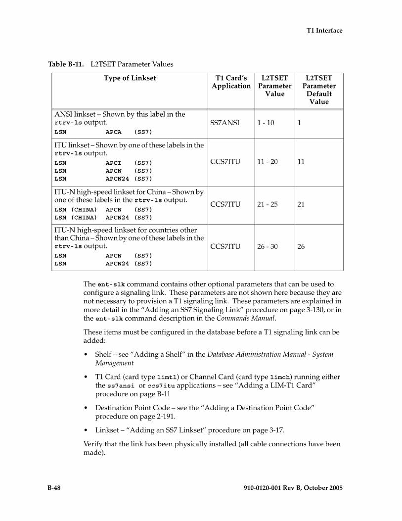
B-48 910-0120-001 Rev B, October 2005
T1 Interface
The ent-slk command contains other optional parameters that can be used to configure a signaling link. These parameters are not shown here because they are not necessary to provision a T1 signaling link. These parameters are explained in more detail in the “Adding an SS7 Signaling Link” procedure on page 3-130, or in the ent-slk command description in the Commands Manual.
These items must be configured in the database before a T1 signaling link can be added:
• Shelf – see “Adding a Shelf” in the Database Administration Manual - System Management
• T1 Card (card type limt1) or Channel Card (card type limch) running either the ss7ansi or ccs7itu applications – see “Adding a LIM-T1 Card” procedure on page B-11
• Destination Point Code – see the “Adding a Destination Point Code” procedure on page 2-191.
• Linkset – “Adding an SS7 Linkset” procedure on page 3-17.
Verify that the link has been physically installed (all cable connections have been made).
Table B-11. L2TSET Parameter Values
Type of Linkset T1 Card’s Application
L2TSET Parameter
Value
L2TSET Parameter
Default Value
ANSI linkset – Shown by this label in the rtrv-ls output.LSN APCA (SS7)
SS7ANSI 1 - 10 1
ITU linkset – Shown by one of these labels in the rtrv-ls output.LSN APCI (SS7)LSN APCN (SS7)LSN APCN24 (SS7)
CCS7ITU 11 - 20 11
ITU-N high-speed linkset for China – Shown by one of these labels in the rtrv-ls output.LSN (CHINA) APCN (SS7)LSN (CHINA) APCN24 (SS7)
CCS7ITU 21 - 25 21
ITU-N high-speed linkset for countries other than China – Shown by one of these labels in the rtrv-ls output.LSN APCN (SS7)LSN APCN24 (SS7)
CCS7ITU 26 - 30 26

T1 Interface
910-0120-001 Rev B, October 2005 B-49
T1 port 2 (t1port=2) cannot be specified when the T1 signaling link is assigned to a channel card (card type limch).
The value of the bps parameter must be either 56000 or 64000.
The values for the ts parameter must be from 1 to 24.
The linkset must be in the database. The number of signaling links in a linkset cannot exceed 16. This can be verified with the rtrv-ls command.
The APC of the linkset assigned to the signaling link must be in the SS7 domain. Use the rtrv-dstn command to verify the domain of the APC of the linkset.
The pcrn1 or pcrn2 parameters can only be specified if the ecm=pcr parameter is specified.
If the T1 signaling link is being assigned to a channel bridged T1 port (shown by the entries MASTER or SLAVE in the CHANBRDG field in the rtrv-t1 output), the T1 port value for the signaling link must be the odd numbered (MASTER) T1 port.
If the T1 card is an E1/T1 MIM, a maximum of 8 T1 signaling links can be assigned to the card. The range of link parameter values is dependent on the type of T1 card the signaling link is assigned to. The link parameter values for T1 signaling links assigned to E1/T1 MIMs are A - A3, or B - B3, allowing a maximum of 8 signaling links on the card.
If the T1 card is an HC MIM, a maximum of 64 T1 signaling links can be assigned to the card. The link parameter values for T1 signaling links assigned to HC MIMs are A - A31, or B - B31.
To configure the EAGLE 5 SAS to perform circular routing detection test on the signaling links, “Configuring Circular Route Detection” procedure on page 3-231.
NOTE: Circular route detection is not supported in ITU networks.
To provision a EAGLE 5 SAS with more than 700 signaling links, the EAGLE 5 SAS must have certain levels of hardware installed. See the “Requirements for EAGLE 5 SASs Containing more than 700 Signaling Links” section on page D-2 for more information on these hardware requirements.
The EAGLE 5 SAS can contain a mixture of low-speed, E1, T1, ATM high-speed, and IP siganling links. The “Determining the Number of High-Speed and Low-Speed Signaling Links” section on page D-2 describes how to determine the quantities of the different types of signaling links the EAGLE 5 SAS can have.

B-50 910-0120-001 Rev B, October 2005
T1 Interface
Example Signaling Link Configuration
This examples used in this procedure are based on Tables B-12.
Canceling the REPT-STAT-SLK and RTRV-SLK Commands
Because the rept-stat-slk and rtrv-slk commands used in this procedure can output information for a long period of time, the rept-stat-slk and rtrv-slk commands can be canceled and the output to the terminal stopped. There are three ways that the rept-stat-slk and rtrv-slk commands can be canceled.
• Press the F9 function key on the keyboard at the terminal where the rept-stat-slk or rtrv-slk commands were entered.
• Enter the canc-cmd without the trm parameter at the terminal where the rept-stat-slk or rtrv-slk commands were entered.
• Enter the canc-cmd:trm=<xx>, where <xx> is the terminal where the rept-stat-slk or rtrv-slk commands were entered, from another terminal other that the terminal where the rept-stat-slk or rtrv-slk commands was entered. To enter the canc-cmd:trm=<xx> command, the terminal must allow Security Administration commands to be entered from it and the user must be allowed to enter Security Administration commands. The terminal’s permissions can be verified with the rtrv-secu-trm command. The user’s permissions can be verified with the rtrv-user or rtrv-secu-user commands.
For more information about the canc-cmd command, go to the Commands Manual.
Table B-12. T1 Signaling Link Configuration Table
SLKLSN SLC TYPE BPS TS T1PORT T1LOC
LOC LINK
1215 A LSNT145 0 LIMT1 56000 3 2 N/A
1216 A LSNT145 1 LIMCH 56000 11 1 1215
1216 A2 LSNT145 2 LIMCH 56000 19 1 1215

T1 Interface
910-0120-001 Rev B, October 2005 B-51
Procedure
1. Display the cards in the database using the rtrv-card command. This is an example of the possible output.
rlghncxa03w 05-09-28 09:12:36 GMT EAGLE5 34.0.0CARD TYPE APPL LSET NAME LINK SLC LSET NAME LINK SLC1101 TSM SCCP 1102 TSM GLS 1113 GSPM EOAM1114 TDM-A1115 GSPM EOAM1116 TDM-B1117 MDAL1201 LIMV35 CCS7ITU lsne12 A 0 1202 LIMV35 CCS7ITU lsne12 A 1 1203 LIMV35 CCS7ITU lsne13 A 0 1204 LIMV35 CCS7ITU lsne13 A 1 1207 LIMT1 SS7ANSI lsnt265 A 0 1208 LIMCH SS7ANSI lsnt265 A 1 lsnt265 A2 2 1211 LIME1 CCS7ITU lsne145 A 0 1212 LIMCH CCS7ITU lsne145 A 1 lsne145 A2 2 1215 LIMT1 SS7ANSI 1216 LIMCH SS7ANSI 1305 LIMOCU CCS7ITU sp6 A 0 sp7 B 01306 LIMOCU CCS7ITU nsp3 A 0 nsp4 B 01307 LIMOCU CCS7ITU nsp1 A 0 1308 LIMOCU CCS7ITU nsp1 A 1 1316 ACMENET STPLAN 1314 LIMOCU CCS7ITU sp7 A 1 sp5 B 01317 TSM SCCP
If the required T1 card or channel card is not in the database, go to the “Adding a LIM-T1 Card” procedure on page B-11 and add the required cards to the database.
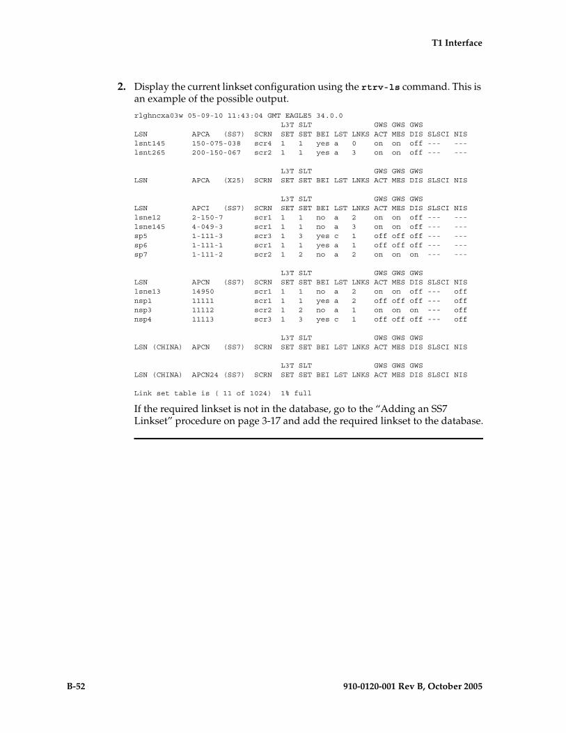
B-52 910-0120-001 Rev B, October 2005
T1 Interface
2. Display the current linkset configuration using the rtrv-ls command. This is an example of the possible output.
rlghncxa03w 05-09-10 11:43:04 GMT EAGLE5 34.0.0 L3T SLT GWS GWS GWSLSN APCA (SS7) SCRN SET SET BEI LST LNKS ACT MES DIS SLSCI NISlsnt145 150-075-038 scr4 1 1 yes a 0 on on off --- ---lsnt265 200-150-067 scr2 1 1 yes a 3 on on off --- ---
L3T SLT GWS GWS GWSLSN APCA (X25) SCRN SET SET BEI LST LNKS ACT MES DIS SLSCI NIS
L3T SLT GWS GWS GWSLSN APCI (SS7) SCRN SET SET BEI LST LNKS ACT MES DIS SLSCI NISlsne12 2-150-7 scr1 1 1 no a 2 on on off --- ---lsne145 4-049-3 scr1 1 1 no a 3 on on off --- ---sp5 1-111-3 scr3 1 3 yes c 1 off off off --- ---sp6 1-111-1 scr1 1 1 yes a 1 off off off --- ---sp7 1-111-2 scr2 1 2 no a 2 on on on --- ---
L3T SLT GWS GWS GWSLSN APCN (SS7) SCRN SET SET BEI LST LNKS ACT MES DIS SLSCI NISlsne13 14950 scr1 1 1 no a 2 on on off --- offnsp1 11111 scr1 1 1 yes a 2 off off off --- offnsp3 11112 scr2 1 2 no a 1 on on on --- offnsp4 11113 scr3 1 3 yes c 1 off off off --- off
L3T SLT GWS GWS GWSLSN (CHINA) APCN (SS7) SCRN SET SET BEI LST LNKS ACT MES DIS SLSCI NIS
L3T SLT GWS GWS GWSLSN (CHINA) APCN24 (SS7) SCRN SET SET BEI LST LNKS ACT MES DIS SLSCI NIS
Link set table is ( 11 of 1024) 1% full
If the required linkset is not in the database, go to the “Adding an SS7 Linkset” procedure on page 3-17 and add the required linkset to the database.

T1 Interface
910-0120-001 Rev B, October 2005 B-53
3. Display the current signaling link configuration using the rtrv-slk command. This is an example of the possible output.
rlghncxa03w 05-09-19 21:16:37 GMT EAGLE5 34.0.0 L2T L1 PCR PCRLOC LINK LSN SLC TYPE SET BPS MODE TSET ECM N1 N21201 A lsne12 0 LIMV35 1 64000 --- --- BASIC --- -----1202 A lsne12 1 LIMV35 1 64000 --- --- BASIC --- -----1203 A lsne13 0 LIMV35 1 64000 --- --- BASIC --- -----1204 A lsne13 1 LIMV35 1 64000 --- --- BASIC --- -----1305 A sp6 0 LIMOCU 1 56000 --- --- BASIC --- -----1305 B sp7 0 LIMOCU 1 64000 DTE --- PCR 76 38001306 A nsp3 0 LIMOCU 1 56000 --- --- BASIC --- -----1306 B nsp4 0 LIMOCU 1 56000 --- --- BASIC --- -----1307 A nsp1 0 LIMOCU 1 56000 --- --- BASIC --- -----1308 A nsp1 1 LIMOCU 1 56000 --- --- BASIC --- -----1314 A sp7 1 LIMOCU 2 64000 DTE --- PCR 76 38001314 B sp5 0 LIMOCU 3 64000 DCE ON BASIC --- -----
LP ATMLOC LINK LSN SLC TYPE SET BPS TSEL VCI VPI LL
LP ATM E1ATMLOC LINK LSN SLC TYPE SET BPS TSEL VCI VPI CRC4 SI SN
No Links Set up.
LOC LINK LSN SLC TYPE IPLIML2
No Links Set up.
LOC LINK LSN SLC TYPE
No Links Set up.
L2T PCR PCR E1 E1LOC LINK LSN SLC TYPE SET BPS ECM N1 N2 LOC PORT TS1211 A lsne145 0 LIME1 1 56000 BASIC --- ----- 1211 2 101212 A lsne145 1 LIMCH 1 56000 BASIC --- ----- 1211 1 141212 A2 lsne145 2 LIMCH 1 56000 BASIC --- ----- 1211 1 20
L2T PCR PCR T1 T1LOC LINK LSN SLC TYPE SET BPS ECM N1 N2 LOC PORT TS1207 A lsnt265 0 LIMT1 1 56000 BASIC --- ----- 1207 2 21208 A lsnt265 1 LIMCH 1 56000 BASIC --- ----- 1207 1 61208 A2 lsnt265 2 LIMCH 1 56000 BASIC --- ----- 1207 1 17
SLK table is (18 of 1200) 2% full.

B-54 910-0120-001 Rev B, October 2005
T1 Interface
NOTE: If the rtrv-slk output in step 3 shows that the maximum number of signaling links is 1500, skip step 4 and go to step 5.
NOTE: If the rtrv-slk output in step 3 shows that the maximum number of signaling links is 1200, and the signaling link being added increases the number beyond 1200, do not perform step 4, but go to “Enabling the Large System # Links Controlled Feature” procedure on page 3-10 and enable the Large System # Links controlled feature for 1500 signaling links. Then go to step 5.
NOTE: If the rtrv-slk output in step 3 shows that the maximum number of signaling links is 1200, and the signaling link being added will not increase the number beyond 1200, skip step 4 and go to step 5.
4. Display the status of the Large System # Links controlled feature by entering the rtrv-ctrl-feat command. The following is an example of the possible output.
rlghncxa03w 05-09-28 21:15:37 GMT EAGLE5 34.0.0The following features have been permanently enabled:
Feature Name Partnum Status QuantityIPGWx Signaling TPS 893012814 on 20000ISUP Normalization 893000201 on ----Command Class Management 893005801 on ----LNP Short Message Service 893006601 on ----Intermed GTT Load Sharing 893006901 on ----XGTT Table Expansion 893006101 on 400000XMAP Table Expansion 893007701 on 3000HC-MIM SLK Capacity 893012707 on 64
The following features have been temporarily enabled:
Feature Name Partnum Status Quantity Trial Period LeftZero entries found.
The following features have expired temporary keys:
Feature Name PartnumZero entries found.
If the Large System # Links controlled feature is not enabled or on, go to “Enabling the Large System # Links Controlled Feature” procedure on page 3-10 and enable the Large System # Links controlled feature for 1500 signaling links. Then go to step 5.
5. Display the T1 interfaces that will be assigned to the T1 signaling link using the rtrv-t1 command with no parameters. This is an example of the possible output.
rlghncxa03w 05-09-19 21:17:04 GMT EAGLE5 34.0.0
LOC T1PORT ENCODE T1TSEL FRAMING LL CHANBRDG1207 1 AMI EXTERNAL ESF 50 ------1215 2 B8ZS LINE SF 100 ------
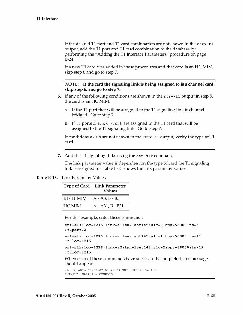
T1 Interface
910-0120-001 Rev B, October 2005 B-55
If the desired T1 port and T1 card combination are not shown in the rtrv-t1 output, add the T1 port and T1 card combination to the database by performing the “Adding the T1 Interface Parameters” procedure on page B-24.
If a new T1 card was added in these procedures and that card is an HC MIM, skip step 6 and go to step 7.
NOTE: If the card the signaling link is being assigned to is a channel card, skip step 6, and go to step 7.
6. If any of the following conditions are shown in the rtrv-t1 output in step 5, the card is an HC MIM.
a If the T1 port that will be assigned to the T1 signaling link is channel bridged. Go to step 7.
b. If T1 ports 3, 4, 5, 6, 7, or 8 are assigned to the T1 card that will be assigned to the T1 signaling link. Go to step 7.
If conditions a or b are not shown in the rtrv-t1 output, verify the type of T1 card.
7. Add the T1 signaling links using the ent-slk command.
The link parameter value is dependent on the type of card the T1 signaling link is assigned to. Table B-13 shows the link parameter values.
For this example, enter these commands.
ent-slk:loc=1215:link=a:lsn=lsnt145:slc=0:bps=56000:ts=3:t1port=2
ent-slk:loc=1216:link=a:lsn=lsnt145:slc=1:bps=56000:ts=11:t1loc=1215
ent-slk:loc=1216:link=a2:lsn=lsnt145:slc=2:bps=56000:ts=19:t1loc=1215
When each of these commands have successfully completed, this message should appear.rlghncxa03w 05-09-07 08:29:03 GMT EAGLE5 34.0.0ENT-SLK: MASP A - COMPLTD
Table B-13. Link Parameter Values
Type of Card Link Parameter Values
E1/T1 MIM A - A3, B - B3
HC MIM A - A31, B - B31

B-56 910-0120-001 Rev B, October 2005
T1 Interface
8. Verify the changes using the rtrv-slk command, specifying the card location and signaling link entered in step 7. This is an example of the possible output.
rtrv-slk:loc=1215
This is an example of the possible output.rlghncxa03w 05-09-19 21:17:04 GMT EAGLE5 34.0.0 L2T PCR PCR T1 T1LOC LINK LSN SLC TYPE SET BPS ECM N1 N2 LOC PORT TS1215 A lsnt145 0 LIMT1 1 56000 BASIC --- ----- 1215 2 3
rtrv-slk:loc=1216
This is an example of the possible output.rlghncxa03w 05-09-19 21:17:04 GMT EAGLE5 34.0.0 L2T PCR PCR T1 T1LOC LINK LSN SLC TYPE SET BPS ECM N1 N2 LOC PORT TS1216 A lsnt145 1 LIMCH 1 56000 BASIC --- ----- 1215 1 111216 A2 lsnt145 2 LIMCH 1 56000 BASIC --- ----- 1215 1 19
9. If any cards contain the first signaling link on a card, those cards must be brought into service with the rst-card command, specifying the location of the card. For this example, enter these commands.
rst-card:loc=1215
rst-card:loc=1216
When each of these commands have successfully completed, this message should appear.rlghncxa03w 05-09-23 13:05:05 GMT EAGLE5 34.0.0Card has been allowed.
10. Activate all signaling links on the cards using the act-slk command, specifying the card location and signaling link specified in step 7. For this example, enter these commands.
act-slk:loc=1215:link=a
act-slk:loc=1216:link=a
act-slk:loc=1216:link=a2
When each of these commands have successfully completed, this message should appear.rlghncxa03w 05-09-07 08:31:24 GMT EAGLE5 34.0.0Activate Link message sent to card

T1 Interface
910-0120-001 Rev B, October 2005 B-57
11. Check the status of the signaling links added in step 7 using the rept-stat-slk command with the card location and signaling link. The state of each signaling link should be in service normal (IS-NR) after the link has completed alignment (shown in the PST field). For this example, enter these commands.
rept-stat-slk:loc=1215:link=a
This is an example of the possible output.rlghncxa03w 05-09-23 13:06:25 GMT EAGLE5 34.0.0SLK LSN CLLI PST SST AST1215,A lsnt145 ----------- IS-NR Avail ---- ALARM STATUS = No Alarms UNAVAIL REASON = -- T1 status = 1215, RCVRY-T1F:FAC-T1 Port 2 available
rept-stat-slk:loc=1216:link=a
This is an example of the possible output.rlghncxa03w 05-09-23 13:06:25 GMT EAGLE5 34.0.0SLK LSN CLLI PST SST AST1216,A lsnt145 ----------- IS-NR Avail ---- ALARM STATUS = No Alarms UNAVAIL REASON = -- T1 status = 1215, RCVRY-T1F:FAC-T1 Port 1 available
rept-stat-slk:loc=1216:link=a2
This is an example of the possible output.rlghncxa03w 05-09-23 13:06:25 GMT EAGLE5 34.0.0SLK LSN CLLI PST SST AST1216,A2 lsnt145 ----------- IS-NR Avail ---- ALARM STATUS = No Alarms UNAVAIL REASON = -- T1 status = 1215, RCVRY-T1F:FAC-T1 Port 1 available
12. Backup the new changes using the chg-db:action=backup:dest=fixed command. These messages should appear, the active Maintenance and Administration Subsystem Processor (MASP) appears first.
BACKUP (FIXED) : MASP A - Backup starts on active MASP.BACKUP (FIXED) : MASP A - Backup on active MASP to fixed disk complete.BACKUP (FIXED) : MASP A - Backup starts on standby MASP.BACKUP (FIXED) : MASP A - Backup on standby MASP to fixed disk complete.
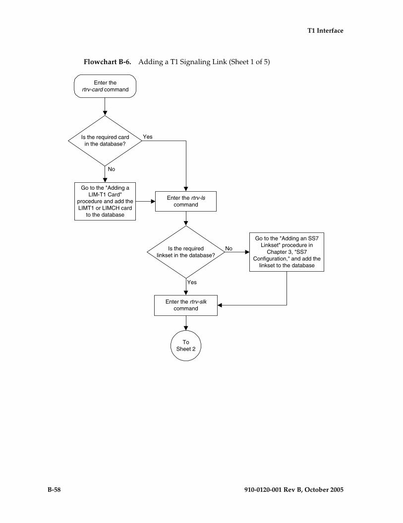
B-58 910-0120-001 Rev B, October 2005
T1 Interface
Flowchart B-6. Adding a T1 Signaling Link (Sheet 1 of 5)
Is the required cardin the database?
Yes
No
Enter the rtrv-lscommand
Enter thertrv-card command
ToSheet 2
Go to the "Adding aLIM-T1 Card"
procedure and add theLIMT1 or LIMCH card
to the database
Enter the rtrv-slkcommand
Is the requiredlinkset in the database?
Yes
No
Go to the "Adding an SS7Linkset" procedure in
Chapter 3, "SS7Configuration," and add the
linkset to the database

T1 Interface
910-0120-001 Rev B, October 2005 B-59
Flowchart B-6. Adding a T1 Signaling Link (Sheet 2 of 5)

B-60 910-0120-001 Rev B, October 2005
T1 Interface
Flowchart B-6. Adding a T1 Signaling Link (Sheet 3 of 5)
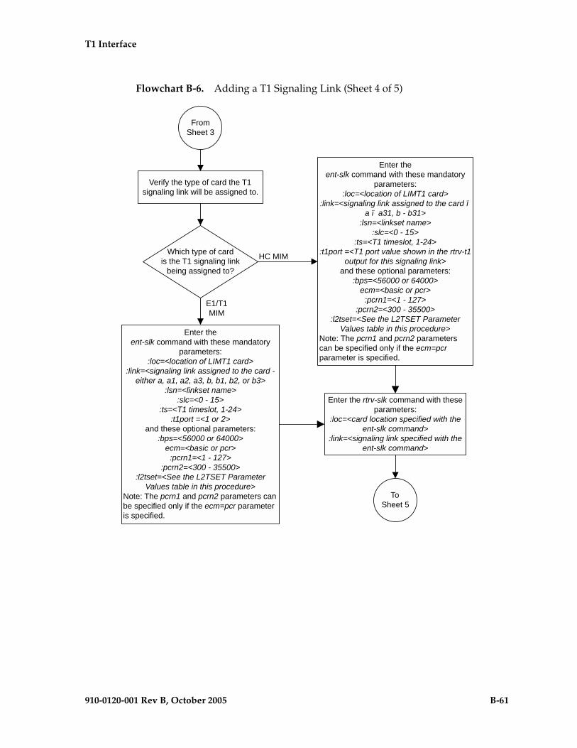
T1 Interface
910-0120-001 Rev B, October 2005 B-61
Flowchart B-6. Adding a T1 Signaling Link (Sheet 4 of 5)

B-62 910-0120-001 Rev B, October 2005
T1 Interface
Flowchart B-6. Adding a T1 Signaling Link (Sheet 5 of 5)

910-0120-001 Rev B, October 2005 C-1
C
ATM Signaling LinkConfiguration
Introduction..................................................................................................... C–1
Overview of the ATM High-Speed Signaling Link LIM Operation........ C–8
ATM High-Speed Signaling Link Testing Capability.............................. C–19
Large MSUs ................................................................................................... C–27
Unsolicted Messages .................................................................................... C–27
ATM High-Speed Signaling Link Configuration ..................................... C–30
Adding a High-Speed LIM-ATM or an E1-ATM LIM............................. C–31
Adding an ATM High-Speed Signaling Link........................................... C–34
Changing an ATM High-Speed Signaling Link Parameter Set.............. C–50
Introduction
ATM (Asynchronous Transfer Mode) is a transport mechanism that uses virtual connections for transporting information across the network. The ATM layer uses the VPI and VCI fields to define multiple Virtual Channel Connections (VCC). Within each VCC, the PTI field is used to distinguish one type of traffic from another. A true ATM switch can support multiple VPI/VCI combinations. The EAGLE 5 SAS supports only a single VPI/VCI combination.
ATM is a specific packet-oriented transfer mode that uses an asynchronous time division multiplexing technique to multiplex information flow in fixed blocks, called cells. ATM replaces MTP-1 (Signaling Data Link Functions) and MTP-2 (Signaling Link Functions) in the SS7 protocol stack.
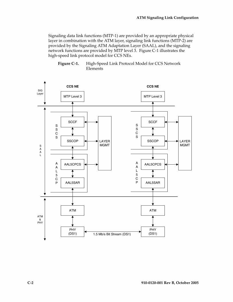
C-2 910-0120-001 Rev B, October 2005
ATM Signaling Link Configuration
Signaling data link functions (MTP-1) are provided by an appropriate physical layer in combination with the ATM layer, signaling link functions (MTP-2) are provided by the Signaling ATM Adaptation Layer (SAAL), and the signaling network functions are provided by MTP level 3. Figure C-1 illustrates the high-speed link protocol model for CCS NEs.
Figure C-1. High-Speed Link Protocol Model for CCS Network Elements
SIGLayer
SAAL
ATM&
PHY
MTP Level 3
CCS NE
SCCF
SSCOP
AAL5CPCS
AAL5SAR
ATM
PHY(DS1)
SSCS
AAL5CP
LAYERMGMT
MTP Level 3
CCS NE
SCCF
SSCOP
AAL5CPCS
AAL5SAR
ATM
PHY(DS1)
SSCS
AAL5CP
LAYERMGMT
1.5 Mb/s Bit Stream (DS1)
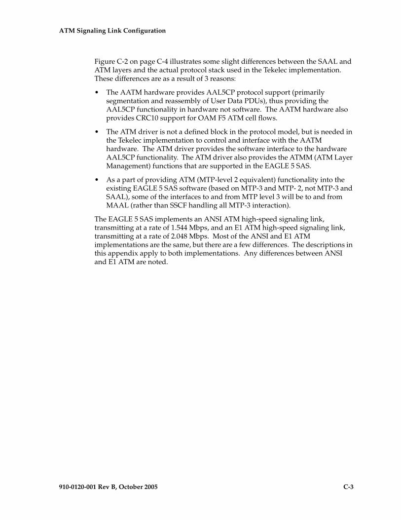
ATM Signaling Link Configuration
910-0120-001 Rev B, October 2005 C-3
Figure C-2 on page C-4 illustrates some slight differences between the SAAL and ATM layers and the actual protocol stack used in the Tekelec implementation. These differences are as a result of 3 reasons:
• The AATM hardware provides AAL5CP protocol support (primarily segmentation and reassembly of User Data PDUs), thus providing the AAL5CP functionality in hardware not software. The AATM hardware also provides CRC10 support for OAM F5 ATM cell flows.
• The ATM driver is not a defined block in the protocol model, but is needed in the Tekelec implementation to control and interface with the AATM hardware. The ATM driver provides the software interface to the hardware AAL5CP functionality. The ATM driver also provides the ATMM (ATM Layer Management) functions that are supported in the EAGLE 5 SAS.
• As a part of providing ATM (MTP-level 2 equivalent) functionality into the existing EAGLE 5 SAS software (based on MTP-3 and MTP- 2, not MTP-3 and SAAL), some of the interfaces to and from MTP level 3 will be to and from MAAL (rather than SSCF handling all MTP-3 interaction).
The EAGLE 5 SAS implements an ANSI ATM high-speed signaling link, transmitting at a rate of 1.544 Mbps, and an E1 ATM high-speed signaling link, transmitting at a rate of 2.048 Mbps. Most of the ANSI and E1 ATM implementations are the same, but there are a few differences. The descriptions in this appendix apply to both implementations. Any differences between ANSI and E1 ATM are noted.
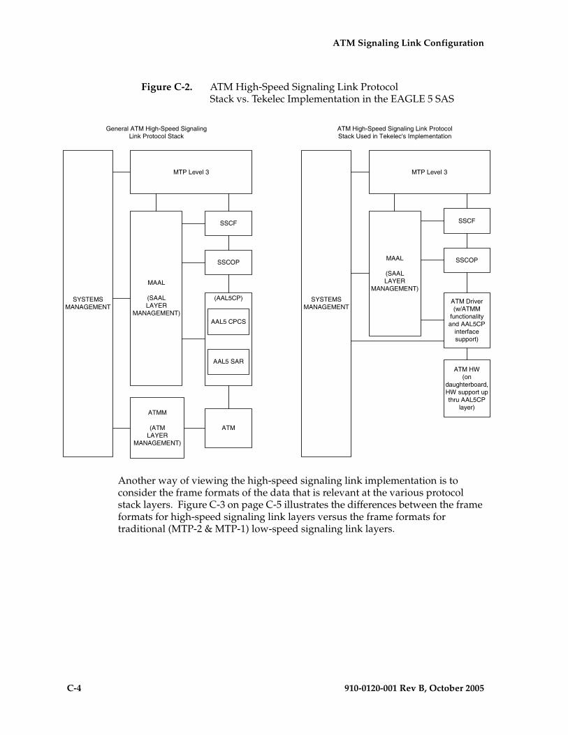
C-4 910-0120-001 Rev B, October 2005
ATM Signaling Link Configuration
Figure C-2. ATM High-Speed Signaling Link Protocol Stack vs. Tekelec Implementation in the EAGLE 5 SAS
Another way of viewing the high-speed signaling link implementation is to consider the frame formats of the data that is relevant at the various protocol stack layers. Figure C-3 on page C-5 illustrates the differences between the frame formats for high-speed signaling link layers versus the frame formats for traditional (MTP-2 & MTP-1) low-speed signaling link layers.
MTP Level 3
General ATM High-Speed SignalingLink Protocol Stack
MAAL
(SAALLAYER
MANAGEMENT)
ATMM
(ATMLAYER
MANAGEMENT)
SSCF
ATM
SYSTEMSMANAGEMENT
SSCOP
AAL5 CPCS
AAL5 SAR
(AAL5CP)
MTP Level 3
ATM High-Speed Signaling Link ProtocolStack Used in Tekelec's Implementation
MAAL
(SAALLAYER
MANAGEMENT)
SSCF
ATM HW(on
daughterboard,HW support upthru AAL5CP
layer)
SYSTEMSMANAGEMENT
SSCOP
ATM Driver(w/ATMM
functionalityand AAL5CP
interfacesupport)
ATM Signaling Link Configuration
910-0120-001 Rev B, October 2005 C-5
Figure C-3. Frame Formats for High-Speed and Low-Speed Signaling Link Protocol Stacks
Based on Figure C-3, the following conclusions can be made regarding the ATM traffic and how ATM is used to carry MTP3 data:
• The ATM layer uses the VPI and VCI fields to define multiple Virtual Channel Connections (VCC). Within each VCC, the PTI field is used to distinguish 1 type of traffic from another. A true ATM switch can support multiple VPI/VCI combinations. The EAGLE 5 SAS high-speed signaling link implementation needs to support only a single VPI/VCI combination.
• The ATM stack contains built in fields that are used to check the integrity of the data that is received across the T1 connection. The ATM cell HEC field and the AAL5CP CRC-32 fields are used for data integrity.
• MTP3 data (or MSUs) is transferred as User Data at the ATM cell level. A single MSU will require 1 or more ATM cells to transfer that MSU.
HSL STACK
MTPLEVEL 3
SIORouting Label
(DPC, OPC, SLS)
SIFManagement orSignaling Info
MTPLEVEL 3
MTP Level 3 Data(from SIO through SIF)
LSL STACK
SSCFSSCF primarily accepts data from the upper layer and passes it down to theSSCOP as user data without adding any SSCF trailer.SSCF also generates and sends SSCF Peer to Peer PDUs. SSCF has only1 SSCF PDU type used for Peer to Peer Msgs. It uses only a 1 byte infofield that contains 'STATUS' of the connection + 3 rsvd (0) bytes...thesePDUs get translated into SSCOP PDUs (like Begin/End connection).The SSCOP layer does not distinguish between SSCF Peer to Peer PDUsversus MTP3 MSUs...both arrive as User Data.
SSCOF
The interface between these layers is usually thehandoff point between the ATM chipset and the
host software
User Data (1-4096 bytes for ATM HSL)
PAD(0-3 bytes)
PL(2 bits)
rsvd(2 bits)
PDU Type(4 bits)
N(s)(3 bytes)
User Data (0 to 4100 bytes for ATM HSL 0 to 65535 in general ATM)
PAD(0-47 bytes)
UU(1 byte)
CPI(1 byte)
Length(2 bytes)
CRC-32(4 bytes)
MTPLEVEL 2
The Signal Unit shown here is for a Message Signal Unit.Message Signal Units are always used to transmit MTP3, andhigher, level data. Other types of Signal Units include LinkStatus Signal Unit (LSSU) and Fill In Signal Units (FISU). Thetype of Signal Unit is differentiated by the LI, length indicator.LSSUs are used to perform many of the MTP2 functions.
ATMUser Data (48 bytes..the AAL5CP_PDU is
broken into 48 byte chunks to be sent over ATM)VPI VPI/VCI VCI
VCI, PTI,CLP
HEC
ATM Header - 5 Bytes
DS1 orE1
MTPLEVEL 1
(DS0)
Physical Transmission Media
DS1 for ANSI ATM HSLsE1 for E1 ATM HSLs
DS0 for LSLs
The SSCOP PDU shownhere is for a SequencedData PDU (SDPDU)...theSSCOP protocol defines15 different PDUs whichare identified via the PDUType field
AAL5CP
AAL5CPCS
AAL5SAR
FLAGBSNBIB
FSNFIB
LI MTP 3 DATA FLAGFCSCK
MTP-2 Hdr MTP-2 Tlr
LegendSCCOF
PAD - A 0-3 byte field used to align the PL field on a 4 byte boundaryPL - Pad Length (0 to 3)PDU Type - indicates the type of SSCOP PDUN(s) - sequence number of this PDU
AAL5CPPAD - used align the overall CP_AAL5_PDU on a 48 byte boundaryUU - User to User (SSCOP to SSCOP) dataCPI - Common Part Indicator, rsvd for later use, currently 0Length - indicates the length of the user dataCRC-32 - calculated over the entire CP_AAL5_PDU
ATMVPI - Virtual Path IdentifierVCI - Virtual Channel IdentifierPTI - Payload Type IndicatorCLP - Cell Loss PriorityHEC - Header Error Control
C-6 910-0120-001 Rev B, October 2005
ATM Signaling Link Configuration
• A significant amount of ATM protocol overhead is involved in transferring MSUs. The overhead includes:
– ATM cell headers
– AAL5CP layer pad bytes and trailer
– SSCOP layer pad bytes and trailer
• In addition to transferring MSUs, the ATM stack is capable of transferring
– SSCOP Peer to Peer Messages - these are used primarily for connection setup and tear down and the acknowledgment of transferred data
– SSCF Peer to Peer Messages - these are used primarily for high-speed signaling link alignment and proving
ATM Protocol Encapsulation
Two main types of data are delivered using ATM: SDUs and OAM cells. SDUs provide peer-to-peer information and user data (MSUs). OAM cells are used for operations and maintenance of the ATM connection. Figure C-4 on page C-7 provides the data encapsulation through the ATM stack. MTP3 is a user of SSCF and passes all PDUs directly to it.
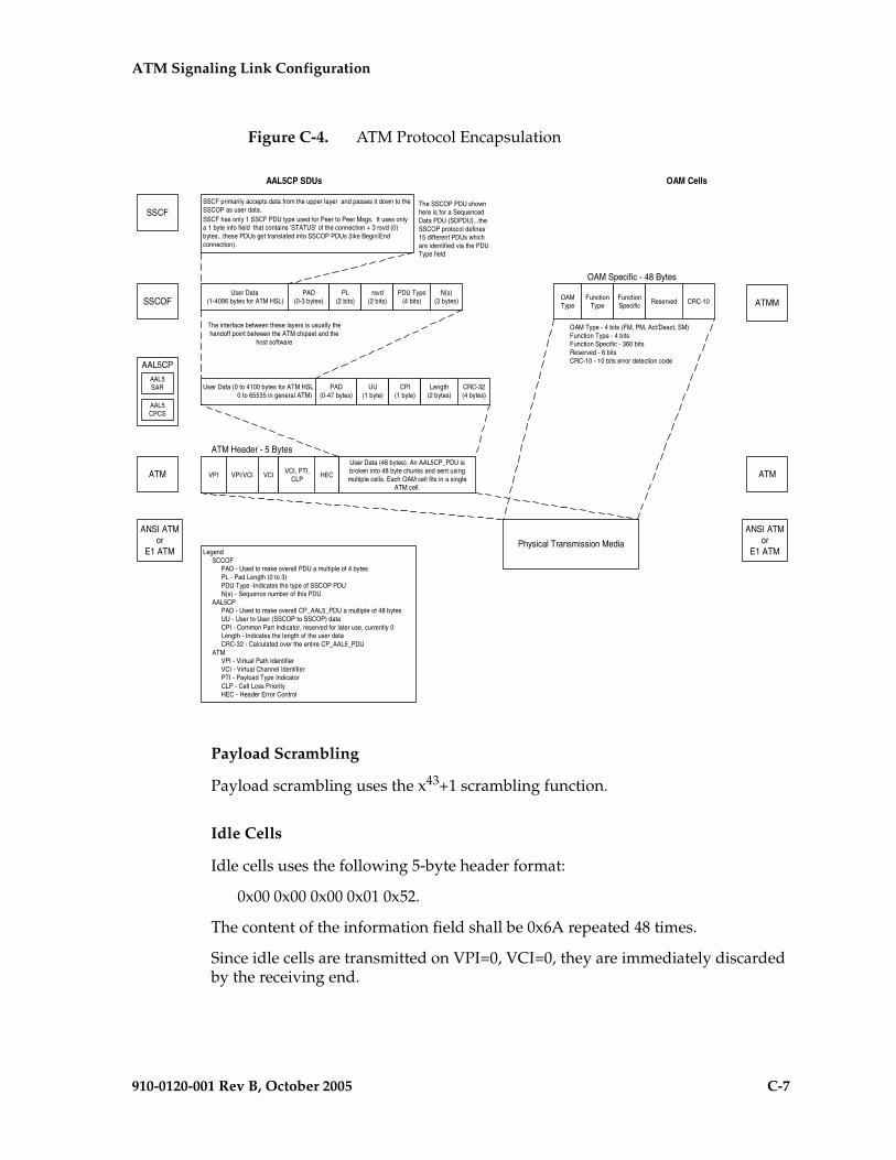
ATM Signaling Link Configuration
910-0120-001 Rev B, October 2005 C-7
Figure C-4. ATM Protocol Encapsulation
Payload Scrambling
Payload scrambling uses the x43+1 scrambling function.
Idle Cells
Idle cells uses the following 5-byte header format:
0x00 0x00 0x00 0x01 0x52.
The content of the information field shall be 0x6A repeated 48 times.
Since idle cells are transmitted on VPI=0, VCI=0, they are immediately discarded by the receiving end.
AAL5CP SDUs OAM Cells
SSCFSSCF primarily accepts data from the upper layer and passes it down to theSSCOP as user data.SSCF has only 1 SSCF PDU type used for Peer to Peer Msgs. It uses onlya 1 byte info field that contains 'STATUS' of the connection + 3 rsvd (0)bytes...these PDUs get translated into SSCOP PDUs (like Begin/Endconnection).
SSCOF
The interface between these layers is usually thehandoff point between the ATM chipset and the
host software
User Data (1-4096 bytes for ATM HSL)
PAD(0-3 bytes)
PL(2 bits)
rsvd(2 bits)
PDU Type(4 bits)
N(s)(3 bytes)
User Data (0 to 4100 bytes for ATM HSL 0 to 65535 in general ATM)
PAD(0-47 bytes)
UU(1 byte)
CPI(1 byte)
Length(2 bytes)
CRC-32(4 bytes)
ATMM
ATMUser Data (48 bytes). An AAL5CP_PDU isbroken into 48 byte chunks and sent usingmultiple cells. Each OAM cell fits in a single
ATM cell.
VPI VPI/VCI VCIVCI, PTI,
CLPHEC
ATM Header - 5 Bytes
ANSI ATMor
E1 ATMPhysical Transmission Media
The SSCOP PDU shownhere is for a SequencedData PDU (SDPDU)...theSSCOP protocol defines15 different PDUs whichare identified via the PDUType field
AAL5CP
AAL5CPCS
AAL5SAR
OAMType
FunctionType
FunctionSpecific
Reserved CRC-10
OAM Specific - 48 Bytes
LegendSCCOF
PAD - Used to make overall PDU a multiple of 4 bytesPL - Pad Length (0 to 3)PDU Type -Indicates the type of SSCOP PDUN(s) - Sequence number of this PDU
AAL5CPPAD - Used to make overall CP_AAL5_PDU a multiple of 48 bytesUU - User to User (SSCOP to SSCOP) dataCPI - Common Part Indicator, reserved for later use, currently 0Length - Indicates the length of the user dataCRC-32 - Calculated over the entire CP_AAL5_PDU
ATMVPI - Virtual Path IdentifierVCI - Virtual Channel IdentifierPTI - Payload Type IndicatorCLP - Cell Loss PriorityHEC - Header Error Control
ATM
OAM Type - 4 bits (FM, PM, Act/Deact, SM)Function Type - 4 bitsFunction Specific - 360 bitsReserved - 6 bitsCRC-10 - 10 bits error detection code
ANSI ATMor
E1 ATM
C-8 910-0120-001 Rev B, October 2005
ATM Signaling Link Configuration
Overview of the ATM High-Speed Signaling Link LIM Operation
To other cards in the EAGLE 5 SAS, the ANSI ATM and E1 ATM high-speed signaling link cards look and operate similar to any other LIMs (with the exception of subtle differences related to load balancing for SCCP traffic), but has the potential for increased data throughput with respect to traditional EAGLE 5 SAS LIMs.
The ANSI and E1 ATM high-speed signaling link cards can perform gateway screening, copy and redirect, conversion and any of the other EAGLE 5 SAS features that any other LIM can perform (with the exception of link fault sectionalization).
A functional block diagram of the ATM high-speed signaling link is shown in Figure C-5.

ATM Signaling Link Configuration
910-0120-001 Rev B, October 2005 C-9
Figure C-5. Functional Block Diagram of ATM High-Speed Signaling Link
MAAL(LAYER MANAGEMENT OF ATM
ADAPTATION LAYER)
LSAC, TCOC,PMTC, other L3
and 'System'Application
ATM or E1ATM
DRIVER(w/ATMMsupport)
SSCOP SSCF
AATM (ANSIATM links) orE1-ATM (E1ATM links)
(AAL5CPSUPPORT)
BUFFERS
(TX, RCV, &SYSTEM)
DIMM BUFFERMGMT
(services used bymany places in
addition to thoseshown...)
HMCGon dest
HMDC HMDT SNM
GWS HMRT SLTM
HMCGon src
CNV
segmentationof large msus
copy & reframe(mpt2) to/from dimm
outbound flowcontrol
get, send,relist, etc...
DUAL PORT RAM
COMM PROCESSOR AND COMM CODE/DATA
IMT
... code and data in fast sram...
ATM equivalent ofMTP Level 1 & 2
Applique
DIMM
DUAL PORT RAM MGMT
C-10 910-0120-001 Rev B, October 2005
ATM Signaling Link Configuration
The following sections provide more details for each of the new applications/processes (indicated by the bold boxes in Figure C-5) required for the ATM high-speed signaling link implementation. These sections will include information such as:
• the specification(s) that defines the layer
• highlights of the functionality provided by the application/process (what problems are being solved here)
• any limitations/restrictions from specifications that apply to the EAGLE 5 SAS implementation
• other information as appropriate
Applique
ANSI ATM
The ANSI ATM hardware consists of an AATM applique connected to an HCAP or HCAP-T main assembly. The AATM hardware provides the following functionality:
• support for the DS1, ATM, and AAL5CP layers of the ATM high-speed signaling link protocol stack as indicated in Figure 1
• DS1 Layer support
– generate DS1 signals
– support for DS1 defect reporting:
" LOS
" LOF
" LCD
" In-band AIS signals
– support for loopback testing at the DS1 level
– support for DS1 performance measurements and performance monitoring
• ATM Layer support
– idle cell insertion/removal
– provide adequate indications of ATM layer errors:
" invalid ATM header patterns
" unsupported VPI/VCI combinations
" unsupported PTI values
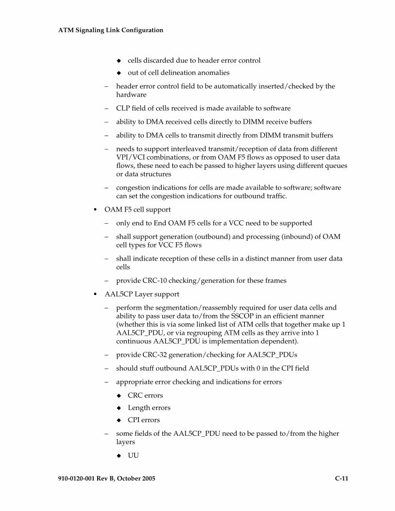
ATM Signaling Link Configuration
910-0120-001 Rev B, October 2005 C-11
" cells discarded due to header error control
" out of cell delineation anomalies
– header error control field to be automatically inserted/checked by the hardware
– CLP field of cells received is made available to software
– ability to DMA received cells directly to DIMM receive buffers
– ability to DMA cells to transmit directly from DIMM transmit buffers
– needs to support interleaved transmit/reception of data from different VPI/VCI combinations, or from OAM F5 flows as opposed to user data flows, these need to each be passed to higher layers using different queues or data structures
– congestion indications for cells are made available to software; software can set the congestion indications for outbound traffic.
• OAM F5 cell support
– only end to End OAM F5 cells for a VCC need to be supported
– shall support generation (outbound) and processing (inbound) of OAM cell types for VCC F5 flows
– shall indicate reception of these cells in a distinct manner from user data cells
– provide CRC-10 checking/generation for these frames
• AAL5CP Layer support
– perform the segmentation/reassembly required for user data cells and ability to pass user data to/from the SSCOP in an efficient manner (whether this is via some linked list of ATM cells that together make up 1 AAL5CP_PDU, or via regrouping ATM cells as they arrive into 1 continuous AAL5CP_PDU is implementation dependent).
– provide CRC-32 generation/checking for AAL5CP_PDUs
– should stuff outbound AAL5CP_PDUs with 0 in the CPI field
– appropriate error checking and indications for errors
" CRC errors
" Length errors
" CPI errors
– some fields of the AAL5CP_PDU need to be passed to/from the higher layers
" UU

C-12 910-0120-001 Rev B, October 2005
ATM Signaling Link Configuration
" CLP
" Congestion indication
E1 ATM
The E1 ATM hardware consists of an E1 ATM applique connected to an HCAP or HCAP-T main assembly. The E1 ATM hardware performs the same functions as the ANSI ATM hardware, with these exceptions:
• support for the E1, ATM, and AAL5CP layers of the ATM high-speed signaling link protocol stack as indicated in Figure C-5 on page C-9.
• E1 layer support
– Support CRC-4
– Support Si and Sn insertion in Channel 0
– Support E1 defect reporting:
" LOS
" LOF
" LCD
• OAM F5 cell support - only end-to-end OAM F5 cells for a VCC are required to be supported
E1 Overview
This section provides an overview of E1, its protocol and characteristics.
Frame Structure
E1 is a 2.048 Mbps interface. It has a frame structure of 256 bits that is repeated at a rate of 8 KHz. The 256-bit frame is broken into 32 eight-bit time timeslots, numbered 0 to 31, as shown in Figure C-6. Timeslots can also be referred to as channels.
Figure C-6. E1 Frame Structure
Si 0 0 1 1 0 1 1
Si 1 A SnSnSnSnSn
Si 0 0 1 1 0 1 1
Si 1 A SnSnSnSnSn
timeslot 1
timeslot 1
timeslot 1
timeslot 1
timeslot 2
timeslot 2
timeslot 2
timeslot 2
............
............
............
............
timeslot 30
timeslot 30
timeslot 30
timeslot 30
timeslot 31
timeslot 31
timeslot 31
timeslot 31
align frame
align frame
non-align frame
non-align frame
Si - International Usage Spare BitSn - National Usage Spare BitA - Alarm Bit

ATM Signaling Link Configuration
910-0120-001 Rev B, October 2005 C-13
Timeslot 0
Timeslot 0 is used for frame alignment and CRC functions. Alternating frames contain the Frame Alignment Signal (FAS), X0011011, where X is supplied from the International Usage Spare Bit information (Si). Frames without the FAS carry Si, Alarm, and Sn information. Bit 1 is set to 1 to prevent accidental emulation of the FAS.
Si is reserved for international usage. CRC-4 specified below is one specific use. If no use is specified, Si should be set to 1. Sn is a 5-bit field (value 0 – 31). ‘A’ is an alarm bit. If set, it indicates a remote alarm indication.
CRC-4
A CRC-4 multi-frame structure is shown in Figure C-7 on page C-14. CRC-4 uses timeslot 0 primarily to aid in frame alignment validation but can be used to monitor error performance as well. A CRC multi-frame consists of timeslot 0 information from 16 consecutive frames. Each CRC-4 multi-frame is divided into 2 eight-frame sub-multi-frames (SMF).
Bit 1 is used to carry 3 different pieces of information:
• A multi-frame alignment word is a repeating 6-bit code (001011) that is located in frames 1,3,5,7,9, and 11.
• A 4-bit CRC code word (C1, C2, C3, C4), which is a data check on the previous 8 E1 frames. The check covers the data for all 32 timeslots. (8 frames * 256 bits/frame = 2048 bits) Each SMF has its own code word. The code word for SMF I is in frames 0, 2, 4 and 6. The code word for SMF II is in frames 8, 10, 12, and 14.
• E (CRC-4 Error indication) bits, present in frames 13 and 15.
The Alarm Indication Signal is received in Channel 0, Bit 3 of the non-alignment frame. If this bit is set, it indicates a Remote Alarm Indication. As with the ANSI ATM, this condition is ignored.
Bits 2 through 8 follow the standard E1 frame structure.
If CRC-4 in on, the provisioned Si information is not used. Instead, bit 0 is used for CRC4 information, CRC4 error reporting, and for multiframe alignment (see Figure C-7).

C-14 910-0120-001 Rev B, October 2005
ATM Signaling Link Configuration
Figure C-7. CRC-4 Multiframe Structure
ATM Mapping into E1
Data channels 1 – 15 and 17 - 31 carries the data for a single ATM channel, as shown in Figure C-8. Note that the ATM cell size does not map directly over the E1 frame format, so the ATM cell can start in any data channel. The data is octet-aligned.
C1 0 0 1 1 0 1 1Frame 0
Frame 1
Frame 2
Frame 3
Frame 4
Frame 5
Frame 6
Frame 7
Frame 8
Frame 9
Frame 10
Frame 11
Frame 12
Frame 13
Frame 14
Frame 15
0 1 A Sn Sn Sn Sn Sn
E 1 A Sn Sn Sn Sn Sn
C2 0 0 1 1 0 1 1
0 1 A Sn Sn Sn Sn Sn
C3 0 0 1 1 0 1 1
1 1 A Sn Sn Sn Sn Sn
C4 0 0 1 1 0 1 1
0 1 A Sn Sn Sn Sn Sn
C1 0 0 1 1 0 1 1
1 1 A Sn Sn Sn Sn Sn
C2 0 0 1 1 0 1 1
1 1 A Sn Sn Sn Sn Sn
C3 0 0 1 1 0 1 1
E 1 A Sn Sn Sn Sn Sn
C4 0 0 1 1 0 1 1
E - CRC-4 Error Indication BitsC1 to C4 - Cyclic Redundancy Check 4 bitsSn - National Spare BitsA - Remote Alarm Indication
Timeslot 0
Sub Multi-Frame I
Sub Multi-Frame II
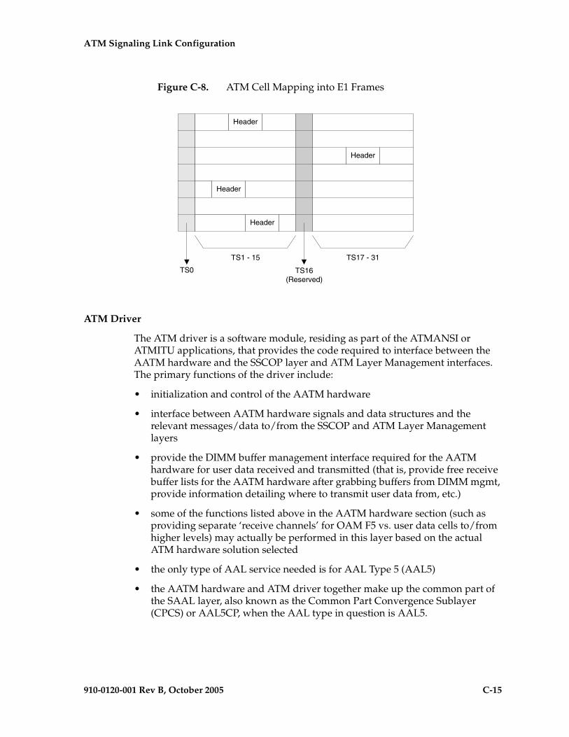
ATM Signaling Link Configuration
910-0120-001 Rev B, October 2005 C-15
Figure C-8. ATM Cell Mapping into E1 Frames
ATM Driver
The ATM driver is a software module, residing as part of the ATMANSI or ATMITU applications, that provides the code required to interface between the AATM hardware and the SSCOP layer and ATM Layer Management interfaces. The primary functions of the driver include:
• initialization and control of the AATM hardware
• interface between AATM hardware signals and data structures and the relevant messages/data to/from the SSCOP and ATM Layer Management layers
• provide the DIMM buffer management interface required for the AATM hardware for user data received and transmitted (that is, provide free receive buffer lists for the AATM hardware after grabbing buffers from DIMM mgmt, provide information detailing where to transmit user data from, etc.)
• some of the functions listed above in the AATM hardware section (such as providing separate ‘receive channels’ for OAM F5 vs. user data cells to/from higher levels) may actually be performed in this layer based on the actual ATM hardware solution selected
• the only type of AAL service needed is for AAL Type 5 (AAL5)
• the AATM hardware and ATM driver together make up the common part of the SAAL layer, also known as the Common Part Convergence Sublayer (CPCS) or AAL5CP, when the AAL type in question is AAL5.
Header
Header
Header
Header
TS1 - 15 TS17 - 31
TS16(Reserved)
TS0

C-16 910-0120-001 Rev B, October 2005
ATM Signaling Link Configuration
E1 ATM Driver
The E1 ATM driver is a software module that provides the interface between the E1 ATM hardware, the SSCOP layer, and ATM Layer Management Module. The E1 ATM driver exists only in the ATMITU application. The basic structure is based upon the ANSI ATM driver present in the ATMANSI application. The primary changes to the existing ANSI ATM driver include:
• initialization and control of the new E1 ATM appliqué.
• remove T1 support of 4 Kbps data link (BOCs, including performance reports and T1 loopback tests)
• verify correct E1 ATM appliqué is installed and reboot if not
SSCOP
The primary task of the SSCOP (Service Specific Connection Oriented Protocol) is to provide assured data delivery between AAL connection endpoints. The SSCOP is 1 of 2 parts (the other being the SSCF) of the Service Specific part of the SAAL layer (also known as the SSCS, the Service Specific Convergence Sublayer of the SAAL). The other part of the SAAL Layer is the CPCS (which was just mentioned in the ATM driver). Breaking the SSCS into 2 sublayers allows a common connection oriented protocol with error recovery (the SSCOP) to provide a generic reliable data transfer service for different AAL interfaces defined by different SSCF layers. The primary functions of the SSCOP layer include:
• transfer of user data with sequence integrity
• error correction by selective retransmission
• flow control
• connection control
• error reporting to layer management
• connection maintenance in the prolonged absence of data transfer
• local data retrieval by the user of the SSCOP
• error detection of protocol control information
• status reporting

ATM Signaling Link Configuration
910-0120-001 Rev B, October 2005 C-17
SSCF
The primary task of the SSCF (Service Specific Coordination Function) is to map the services provided by the lower layers of the SAAL to the needs of a specific higher layer user. For the ATM high-speed signaling link, the higher layer user is the MTP-3 protocol.
• maps signals/primitives from MTP-3 (SSCF user) to SSCOP, and vice versa.
• performs local retrieve function, required by the changeover order.
• flow control on transmit direction (SSCF notifies the user of congestion levels)
• maintains and controls the link status
• generates necessary reports to ATM Layer Management (primarily the cause for the release of the SSCOP connection)
• implements some SSCF to SSCF, peer to peer messages primarily related to connection establishment and release
• controls local and remote processor outage and recovery
• controls the alignment procedure
For an E1 ATM high-speed signaling link, the link proving default values are significantly different compared to an ANSI ATM high-speed signaling link. Table C-1 illustrates the different link proving values.
The time required for normal ANSI proving is approximately 60 seconds (925 µsec/pdu * 64552 PDUs = 60 seconds). This time is greater than TmrT2 value for an E1 ATM high-speed signaling link (30 seconds), so a link with E1 ATM defaults would have gone out of service before a link with ANSI ATM defaults finishes proving. Thus, great care must be taken to ensure that compatible proving numbers are assigned to a signaling link.
Table C-1. Link Proving Differences Between ITU and ANSI
CHG-ATM-LPS Parameter Name
Description E1 ATM Default Values
ANSI ATM Default Values
N1 Number of PDUs sent during link proving 1000 64552
TmrT2 Time to attempt link proving 30 sec 120 sec
maxnrp Maximum number of retransmitted PDUs during proving
0 1
TmrT3 Time between proving PDUs 925 µsec 925 µsec

C-18 910-0120-001 Rev B, October 2005
ATM Signaling Link Configuration
ATM and SAAL Layer Management Interfaces
The primary task of the ATM and SAAL layer management layers is to map requests and indications between the system management for the EAGLE 5 SAS and the individual ATM, AAL5CP, SSCOP, and SSCF layers. This functionality is actually achieved using two management modules, which both interface to the system management.
ATM Layer Management
ATM layer management is achieved with the ATMM (ATM layer management module). The ATMM provides a supporting role for system management functions which include fault, performance, configuration, security and resource management functions. It is the job of the system management to coordinate with different layers locally to perform all tasks associated with these functions. The ATMM entity uses two types of interactions with the ATM entity to perform its functions. The first type of interaction is for the exchange of info between the ATM and ATMM entity. The second type of interaction is for peer to peer communication between ATMM entities (between the two nodes on both ends of the high-speed signaling link). This second interaction is achieved by sending and receiving and processing OAM F5 cells in the ATM high-speed signaling link implementation. The primary functions provided by the ATMM for an ANSI ATM high-speed signaling link include:
• OAM F5 fault management: includes alarm surveillance, loopback using OAM cells, and continuity check
• OAM F5 performance management: includes activation and deactivation of performance monitoring, forward and backward monitoring and reporting of performance to system management.
NOTE: The general ATMM layer is capable of performing performance management functionality. The ATMM layer implemented by ATM high-speed signaling link does not support this capability.
The primary functions provided by the ATMM for an E1 ATM high-speed signaling link include only OAM F5 fault management: loopback by OAM cells. All other forms of OAM F5 management and OAM F5 performance management are not supported.

ATM Signaling Link Configuration
910-0120-001 Rev B, October 2005 C-19
SAAL Layer Management
The SAAL layer management includes interfaces to and from AAL5CP, SSCOP, SSCF, and system management. SAAL layer management supports the following functions:
• error processing for these layers
• error monitoring for in-service links
• detection of excessive time with no credit
• detection of closely spaced SSCOP recoveries
• measurements
• duration of presence in the in-service state
• signaling link failures
• signaling link restoration
• handling of processor outage conditions
• management of signaling link proving
ATM High-Speed Signaling Link Testing Capability
Local Loopback Support
There are five link testing capabilities for an ATM high-speed signaling link. All five of these tests can be used for an ANSI ATM high-speed signaling link; three of these tests can be used for an E1 ATM high-speed signaling link. Table C-2 gives a description of each test and shows which the type of ATM high-speed signaling link each test can be used. Figures C-9 and C-10 show diagrams of each test.

C-20 910-0120-001 Rev B, October 2005
ATM Signaling Link Configuration
Table C-2. ATM High-Speed Signaling Link Loopback Support
Loopback Type
The Type of ATM
High-Speed Link the Test
can be Applied to
When can the Loopback Test be Performed
How does the Loopback Test
Work
What is Tested (Assume Near End Unless Specified)
ANSI E1
SLTC Yes YesWhen the link is in service and activated
MTP-3 exchanges SLTM/SLTA messages with remote MTP-3. Appears as normal MSU traffic to SSCF and SSCOP.
MTP-3 layer, ATM protocol stack (near end and far end), and wire
OAM Yes Yes
When the link is connected to a remote STP. The state of the link is either activated or deactivated.
ATM driver exchanges OAM F5 Loopback cells with remote ATM driver. One OAM cell per request with a maximum of three attempts made.
ATM driver (near end and far end) and wire
LXVR Yes Yes When the link is deactivated.
MTP-3 attempts to align link. If alignment fails, test fails. Appears as normal alignment request to SSCF and SSCOP.
SSCF, SSCOP, ATM driver and T1 hardware (for an ANSI ATM high-speed link) or E1 hardware (for an E1 ATM high-speed signaling link) on near end
Payload Yes No
When the link is deactivated, connected to remote STP and no Yellow Alarm BOC is being transmitted.
MTP-3 attempts to align link. If alignment fails, test fails. Appears as normal alignment request to SSCF and SSCOP.
SSCF, SSCOP, ATM driver (near end only) and T1 hardware (near end and far end) and wire
Line Yes No
When the link is deactivated and connected to remote STP and no Yellow Alarm BOC is being transmitted.
MTP-3 attempts to align link. If alignment fails, test fails. Appears as normal alignment request to SSCF and SSCOP.
SSCF, SSCOP, ATM driver (near end only) and T1 hardware (near end and far end) and wire

ATM Signaling Link Configuration
910-0120-001 Rev B, October 2005 C-21
Figure C-9. ANSI ATM High-Speed Signaling Link Loopback Support
MTP-3
SSCF/SCCOP
ATM Driver
T1Hardware
MTP-3
SSCF/SCCOP
ATM Driver
T1Hardware
MTP-3
SSCF/SCCOP
ATM Driver
T1Hardware
MTP-3
SSCF/SCCOP
ATM Driver
T1Hardware
MTP-3
SSCF/SCCOP
ATM Driver
T1Hardware
MTP-3
SSCF/SCCOP
ATM Driver
T1Hardware
SLTC Loopbacktst-slk:loopback=sltc
LOCAL_TRANSCEIVER(DS1) Loopback
tst-slk:loopback=lxvr
OAM Loopbacktst-slk:loopback=oam
Near End Far End Near End Far End Near End Far End
MTP-3
SSCF/SCCOP
ATM Driver
T1 Hardware
MTP-3
SSCF/SCCOP
ATM Driver
T1 Hardware
Payload Loopbacktst-slk:loopback=payload
Near End Far End
MTP-3
SSCF/SCCOP
ATM Driver
T1 Hardware
MTP-3
SSCF/SCCOP
ATM Driver
T1 Hardware
Line Loopbacktst-slk:loopback=line
Near End Far End
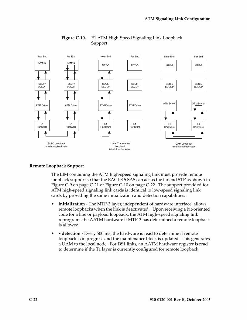
C-22 910-0120-001 Rev B, October 2005
ATM Signaling Link Configuration
Figure C-10. E1 ATM High-Speed Signaling Link Loopback Support
Remote Loopback Support
The LIM containing the ATM high-speed signaling link must provide remote loopback support so that the EAGLE 5 SAS can act as the far end STP as shown in Figure C-9 on page C-21 or Figure C-10 on page C-22. The support provided for ATM high-speed signaling link cards is identical to low-speed signaling link cards by providing the same initialization and detection capabilities.
• initialization - The MTP-3 layer, independent of hardware interface, allows remote loopbacks when the link is deactivated. Upon receiving a bit-oriented code for a line or payload loopback, the ATM high-speed signaling link reprograms the AATM hardware if MTP-3 has determined a remote loopback is allowed.
• • detection - Every 500 ms, the hardware is read to determine if remote loopback is in progress and the maintenance block is updated. This generates a UAM to the local node. For DS1 links, an AATM hardware register is read to determine if the T1 layer is currently configured for remote loopback.
MTP-3
SSCF/SCCOP
ATM Driver
E1Hardware
MTP-3
SSCF/SCCOP
ATM Driver
E1Hardware
Near End Far End
SLTC Loopbacktst-slk:loopback=sltc
MTP-3
SSCF/SCCOP
ATM Driver
E1Hardware
MTP-3
SSCF/SCCOP
ATM Driver
E1Hardware
Near End Far End
OAM Loopbacktst-slk:loopback=oam
MTP-3
SSCF/SCCOP
ATM Driver
E1Hardware
MTP-3
SSCF/SCCOP
ATM Driver
E1Hardware
Near End Far End
Local TransceiverLoopback
tst-slk:loopback=lxvr
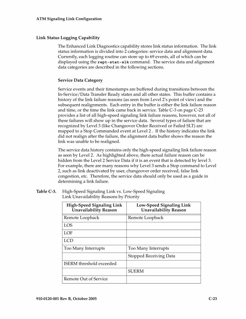
ATM Signaling Link Configuration
910-0120-001 Rev B, October 2005 C-23
Link Status Logging Capability
The Enhanced Link Diagnostics capability stores link status information. The link status information is divided into 2 categories: service data and alignment data. Currently, each logging routine can store up to 69 events, all of which can be displayed using the rept-stat-slk command. The service data and alignment data categories are described in the following sections.
Service Data Category
Service events and their timestamps are buffered during transitions between the In-Service/Data Transfer Ready states and all other states. This buffer contains a history of the link failure reasons (as seen from Level 2’s point of view) and the subsequent realignments. Each entry in the buffer is either the link failure reason and time, or the time the link came back in service. Table C-3 on page C-23 provides a list of all high-speed signaling link failure reasons, however, not all of these failures will show up in the service data. Several types of failure that are recognized by Level 3 (like Changeover Order Received or Failed SLT) are mapped to a Stop Commanded event at Level 2 . If the history indicates the link did not realign after the failure, the alignment data buffer shows the reason the link was unable to be realigned.
The service data history contains only the high-speed signaling link failure reason as seen by Level 2. As highlighted above, there actual failure reason can be hidden from the Level 2 Service Data if it is an event that is detected by level 3. For example, there are many reasons why Level 3 sends a Stop command to Level 2, such as link deactivated by user, changeover order received, false link congestion, etc. Therefore, the service data should only be used as a guide in determining a link failure.
Table C-3. High-Speed Signaling Link vs. Low-Speed Signaling Link Unavailability Reasons by Priority
High-Speed Signaling Link Unavailability Reason
Low-Speed Signaling Link Unavailability Reason
Remote Loopback Remote Loopback
LOS
LOF
LCD
Too Many Interrupts Too Many Interrupts
Stopped Receiving Data
ISERM threshold exceeded
SUERM
Remote Out of Service
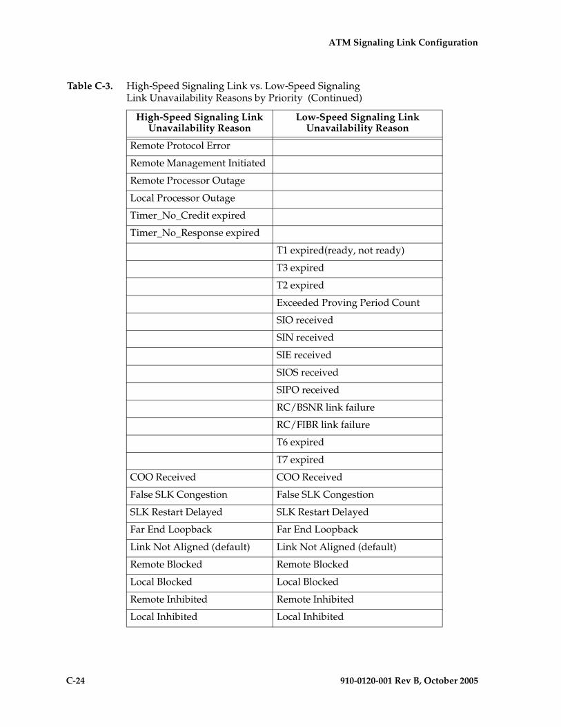
C-24 910-0120-001 Rev B, October 2005
ATM Signaling Link Configuration
Remote Protocol Error
Remote Management Initiated
Remote Processor Outage
Local Processor Outage
Timer_No_Credit expired
Timer_No_Response expired
T1 expired(ready, not ready)
T3 expired
T2 expired
Exceeded Proving Period Count
SIO received
SIN received
SIE received
SIOS received
SIPO received
RC/BSNR link failure
RC/FIBR link failure
T6 expired
T7 expired
COO Received COO Received
False SLK Congestion False SLK Congestion
SLK Restart Delayed SLK Restart Delayed
Far End Loopback Far End Loopback
Link Not Aligned (default) Link Not Aligned (default)
Remote Blocked Remote Blocked
Local Blocked Local Blocked
Remote Inhibited Remote Inhibited
Local Inhibited Local Inhibited
Table C-3. High-Speed Signaling Link vs. Low-Speed Signaling Link Unavailability Reasons by Priority (Continued)
High-Speed Signaling Link Unavailability Reason
Low-Speed Signaling Link Unavailability Reason

ATM Signaling Link Configuration
910-0120-001 Rev B, October 2005 C-25
Alignment Data Category
Alignment events are buffered at all times when link is not in service. Only the first unique occurrence of an event and its timestamp is buffered. High-speed signaling link alignment events are divided into:
• SSCOP, SSCF and MAAL state transitions
• SSCOP and SSCF transmitted PDUs
• SSCOP and SSCF received PDUs
• Special level 1 events.
Tables C-4, C-5, and C-6 list all the possible alignment events sorted by event type.
Table C-4. High-Speed Signaling Link State Transition Alignment Events
SSCOP SSCF MAAL
Idle OOS Idle OOS
Outgoing Conn. Pending OOS ODP Alignment
Incoming Conn. Pending Alignment Idle Proving
Outgoing Disc. Pending Alignment OCP Aligned/Ready
Outgoing Resync Pending Alignment ODP In Service
Incoming Resync Pending Proving Data Transfer Ready
Outgoing Recovery Pending Aligned/Ready Data Transfer Ready
Recovery Response Pending In Service/Data Transfer Ready
Incoming Recovery Pending
Data Transfer Ready
Table C-5. High-Speed Signaling Link Transmitted/Received Alignment PDUs
SSCOP SSCF
BGN Out of Service
BGAK Processor Outage
END In Service
ENDAK Normal
RS Emergency
RSAK Alignment Not Successful
BGREJ Mgmt Initiated
SD Protocol Error

C-26 910-0120-001 Rev B, October 2005
ATM Signaling Link Configuration
Display of Buffered Data
The buffered data are displayed using the rept-stat-slk command. All events are buffered with the day and time of the event. The buffered timestamp is displayed in a day of year and time of day format (YY-MM-DD HH:MM:SS.sss). The time of day and day of year are passed to the LIM card when polling for the maintenance block. A timer on the LIM card, with a 5 millisecond granularity, provides the millisecond portion of the time displayed. The user has the ability to request either alignment data, service data or both be displayed. A maximum of 69 service and/or alignment events are displayed. However, the user has the ability to display only the last 10 alignment events. See the Commands Manual for a description of the rept-stat-slk command.
ER Proving Not Successful
POLL
STAT
USTAT
UD
MD
ERAK
Table C-6. High-Speed Signaling Link Special Level 1 Alignment Events
Special Events
LCD
LCD Cleared
LOF
LOF Cleared
LOS
LOS Cleared
Too Many Interrupts
Stop Commanded
Table C-5. High-Speed Signaling Link Transmitted/Received Alignment PDUs (Continued)
SSCOP SSCF

ATM Signaling Link Configuration
910-0120-001 Rev B, October 2005 C-27
Large MSUs
As shown in Figure C-3 on page C-5, a general purpose implementation of the ATM high-speed signaling link protocol stack would allow for large MSUs to be transferred across an ANSI or E1 ATM high-speed signaling link. The SSCOP layer can handle user data from SSCF that is up to 4096 bytes long. Since the SSCF layer does not add a trailer to MTP3 data, the ATM protocol stack is able to transfer MTP3 data packets up to 4096 bytes. When the SSCOP trailer is added, 4100 bytes of user data are handed to the AAL5CP layer.
These MSU sizes are much larger than the MTP3 data size currently supported by a low-speed signaling link. Currently, the largest MSU transferred on a low-speed signaling link is 279 bytes (2 flag bytes, 3 level 2 header bytes, 2 FCS bytes, and 272 bytes of MTP3 data). A large MSU is any MSU that contains 273 to 4096 bytes of MTP data.
The ATM high-speed signaling link (ANSI or E1) does not support large MSUs. Either UIM 1172 or 1173 is generated when a large MSU is received. See the “UIMs” section on page C-29 for more information on these UIMs.
Unsolicited Messages
There are two types of unsolicited messages that are generated, alarm messages (UAMs) and information messages (UIMs).
Link Unavailability UAMs
The signaling link UAM format includes a CLASS output. This identifies the corresponding link as either an MTP2 or SAAL link class (the SAAL link class is used for high-speed signaling links).
Example:
0044.0200 SLK 1201,A sp1 RCVRY-LKF: link available SLC=01 FECLLI=A1234567890 CLASS=SAAL
0044.0200 SLK 1202,A sp2 RCVRY-LKF: link available SLC=01 FECLLI=A1234567890 CLASS=MTP2
Table C-3 on page C-23 provides a summary of high-speed signaling link and low-speed signaling link unavailable reasons listed from highest priority to lowest.
Table C-7 on page C-28 shows the UAMs that correspond link failures on an high-speed signaling link. All signaling link alarms have a severity level of major, except for UAM 200, which shows that the link failure has been cleared. All alarms are output to the Link Maintenance output group.

C-28 910-0120-001 Rev B, October 2005
ATM Signaling Link Configuration
Table C-7. Signaling Link Unsolicited Alarm Messages
Link Failure UAM Number
UAM Text
Recovery: Link Available 0200 RCVRY-LKF: link available
Failure: Remote NE Loopback 0201 REPT-LKF: remote NE loopback
Failure: Hardware Problems 0202 REPT-LKF: HWP - too many link interrupts
Failure: Failed Remote FE Loopback 0202 REPT-LKF: remote FE loopback
Failure: MTP3 Changeover Order (COO) Message Received 0218 REPT-LKF: COO - rcvd changeover order
Management Inhibit: Remote 0234 REPT-LKF: RMI remote inhibited
Management Inhibit: Local 0235 REPT-LINK-MGTINH: local inhibited
Failure: Unresolved - Default failure reason 0236 REPT-LKF: not aligned
Failure: False Congestion Restart 0236 REPT-LKF: false congestion restart
Failure: MTP Link Restart Delayed 0236 REPT-LKF: MTP link restart delayed
Excessive Duration of Far End Receiving Congestion 0237 REPT-LKF: LM Timer NO-CREDIT
expired
Excessive Delay of Acknowledgment 0238 REPT-LKF: XDA - Timer NO-RESPONSE expired
Local Processor Outage(management initiated) 0239 REPT-LKF: MBL - local processor outage
SSCF Remote Release: Remote Processor Outage 0240 REPT-LKF: rcvd SSCOP END-proc.
outage
SSCF Remote Release: Out of Service 0241 REPT-LKF: rcvd SSCOP END-out of service
SSCF Remote Release: Protocol Error 0242 REPT-LKF: rcvd SSCOP END-protocol error
SSCF Remote Release: Management Initiated 0243 REPT-LKF: rcvd SSCOP END-mgmnt
initiated
Facility Outage - DS1 Loss of Signal failure 0244 REPT-LKF: FAC - DS1 LOS failure
Facility Outage - DS1 Loss of Frame failure 0245 REPT-LKF: FAC - DS1 LOF failure
Facility Outage - DS1 Loss of Cell Delineation failure 0246 REPT-LKF: FAC - DS1 LCD failure
Excessive In Service Error Rate 0247 REPT-LKF: XER - ISERM threshold exceeded

ATM Signaling Link Configuration
910-0120-001 Rev B, October 2005 C-29
UIMs
There are two types UIMs generated with ATM high-speed signaling links, UIMs for large MSUs and UIMs for the loopback tests. UIMs 1172 and 1173 are generated for MTP MSUs (1172) and SCCP MSUs (1173).
The large MSUs are discarded at the receiving ATM high-speed signaling link rather than the outbound link.
UIM 1172 Example
0018.1172 CARD 1103 INFO REPT-OVSZMSG: MTP MSU too large to route. LEN=279 SIO=03 DPC=001-001-001 OPC=002-002-002 LSN=A1234567 Report Date: 97-10-30 Time: 16:27:19
UIM 1173 Example
0018.1173 CARD 1103 INFO REPT-OVSZMSG: SCCP MSU too large to route. LEN=279 SIO=03 DPC=001-001-001 OPC=002-002-002 MSG TYPE=09 CDPA: AI=8B PC=003-003-003 SSN=005 TT=250 ADDR=1234567890 CGPA: AI=8B PC=004-004-004 SSN=006 TT=251 ADDR=0123456789 LSN=A1234567 Report Date: 97-10-30 Time: 16:27:19
The UIMs shown in Table C-8 are generated when loopback tests performed on the ATM high-speed signaling link are completed.
Table C-8. Table 5 : Loopback Test UIMs
UIM # Severity Message Text UIM is Generated When …
1156 None Loopback success loopback test passes.
1157 None Loopback failed loopback test failed.
1158 None Loopback aborted request to activate link is received while running a loopback.
1159 None Loopback in progress loopback request received while the same loopback test is already in progress.
1170 None Loopback prevented
loopback setup was not performed because the specified type of loopback requires a BOC to be transmitted and this function was prevented from transmitting a BOC.
1171 None Loopback invalidloopback setup was not performed because invalid parameters were provided.

C-30 910-0120-001 Rev B, October 2005
ATM Signaling Link Configuration
ATM High-Speed Signaling Link Configuration
An ATM high-speed signaling link is configured using these commands:
• ent-card - Used to add the either the ANSI ATM or E1 ATM LIMs
• ent-slk - Used to add the signaling link
• chg-atm-lps - Used to change the ATM signaling link parameters. The ATM signaling link parameters control the behavior of the ATM high-speed signaling links. These parameters are not configured with the ent-slk command and are assigned default values when the ATM high-speed signaling link is added to the database.
To configure an ATM high-speed signaling link, perform these procedures:
• “Adding a High-Speed LIM-ATM or an E1-ATM LIM” procedure on page C-31
• “Adding an ATM High-Speed Signaling Link” procedure on page C-34
• “Changing an ATM High-Speed Signaling Link Parameter Set” procedure on page C-50.
Procedures for configuring the linksets and routes, and for removing SS7 signaling links (which includes ATM high-speed signaling links), are contained in Chapter 3, “SS7 Configuration.” The procedure for removing the LIM containing the ATM high-speed signaling link is contained in the Database Administration Manual - System Management. These procedures contain no information that is specific to ATM high-speed signaling links, therefore, are not included in this appendix.
The procedures contained in this appendix use a variety of commands. If more information on these commands is needed, go to the Commands Manual to find the required information.
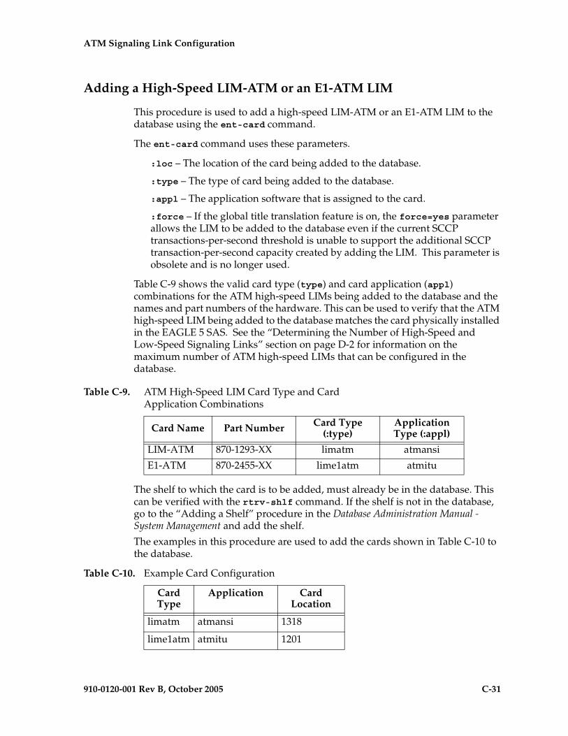
ATM Signaling Link Configuration
910-0120-001 Rev B, October 2005 C-31
Adding a High-Speed LIM-ATM or an E1-ATM LIM
This procedure is used to add a high-speed LIM-ATM or an E1-ATM LIM to the database using the ent-card command.
The ent-card command uses these parameters.
:loc – The location of the card being added to the database.
:type – The type of card being added to the database.
:appl – The application software that is assigned to the card.
:force – If the global title translation feature is on, the force=yes parameter allows the LIM to be added to the database even if the current SCCP transactions-per-second threshold is unable to support the additional SCCP transaction-per-second capacity created by adding the LIM. This parameter is obsolete and is no longer used.
Table C-9 shows the valid card type (type) and card application (appl) combinations for the ATM high-speed LIMs being added to the database and the names and part numbers of the hardware. This can be used to verify that the ATM high-speed LIM being added to the database matches the card physically installed in the EAGLE 5 SAS. See the “Determining the Number of High-Speed and Low-Speed Signaling Links” section on page D-2 for information on the maximum number of ATM high-speed LIMs that can be configured in the database.
The shelf to which the card is to be added, must already be in the database. This can be verified with the rtrv-shlf command. If the shelf is not in the database, go to the “Adding a Shelf” procedure in the Database Administration Manual - System Management and add the shelf.
The examples in this procedure are used to add the cards shown in Table C-10 to the database.
Table C-9. ATM High-Speed LIM Card Type and Card Application Combinations
Card Name Part Number Card Type (:type)
Application Type (:appl)
LIM-ATM 870-1293-XX limatm atmansi
E1-ATM 870-2455-XX lime1atm atmitu
Table C-10. Example Card Configuration
Card Type
Application Card Location
limatm atmansi 1318
lime1atm atmitu 1201

C-32 910-0120-001 Rev B, October 2005
ATM Signaling Link Configuration
Procedure
1. Display the cards in the database using the rtrv-card command. This is an example of the possible output.rlghncxa03w 05-09-28 09:12:36 GMT EAGLE5 34.0.0CARD TYPE APPL LSET NAME LINK SLC LSET NAME LINK SLC1102 TSM GLS 1113 GSPM EOAM1114 TDM-A1115 GSPM EOAM1116 TDM-B1117 MDAL1117 MDAL1201 LIMDS0 SS7ANSI sp2 A 0 sp1 B 01203 LIMDS0 SS7ANSI sp3 A 0 1204 LIMDS0 SS7ANSI sp3 A 1 1206 LIMDS0 SS7ANSI nsp3 A 1 nsp4 B 11207 LIMV35 SS7GX25 nsp1 A 0 1208 LIMV35 SS7GX25 nsp1 A 1 1216 ACMENET STPLAN 1301 TSM SCCP 1308 LIMDS0 SS7ANSI sp6 A 1 sp7 B 01314 LIMDS0 SS7ANSI sp7 A 1 sp5 B 11317 ACMENET STPLAN
The cards should be distributed throughout the EAGLE 5 SAS for proper power distribution. Refer to the Installation Manual - EAGLE 5 SAS for the shelf power distribution.
2. Using Table C-9 on page C-31 as a reference, verify that the card has been physically installed into the proper location.
3. Add the card using the ent-card command. For this example, enter these commands.
ent-card:loc=1318:type=limatm:appl=atmansi
ent-card:loc=2101:type=lime1atm:appl=atmitu
When each of these commands have successfully completed, this message should appear.rlghncxa03w 05-09-12 09:12:36 GMT EAGLE5 34.0.0ENT-CARD: MASP A - COMPLTD
4. Verify the changes using the rtrv-card command with the card location specified. For this example, enter these commands.
rtrv-card:loc=1318
This is an example of the possible output.
rlghncxa03w 05-09-28 09:12:36 GMT EAGLE5 34.0.0CARD TYPE APPL LSET NAME LINK SLC LSET NAME LINK SLC1318 LIMATM ATMANSI
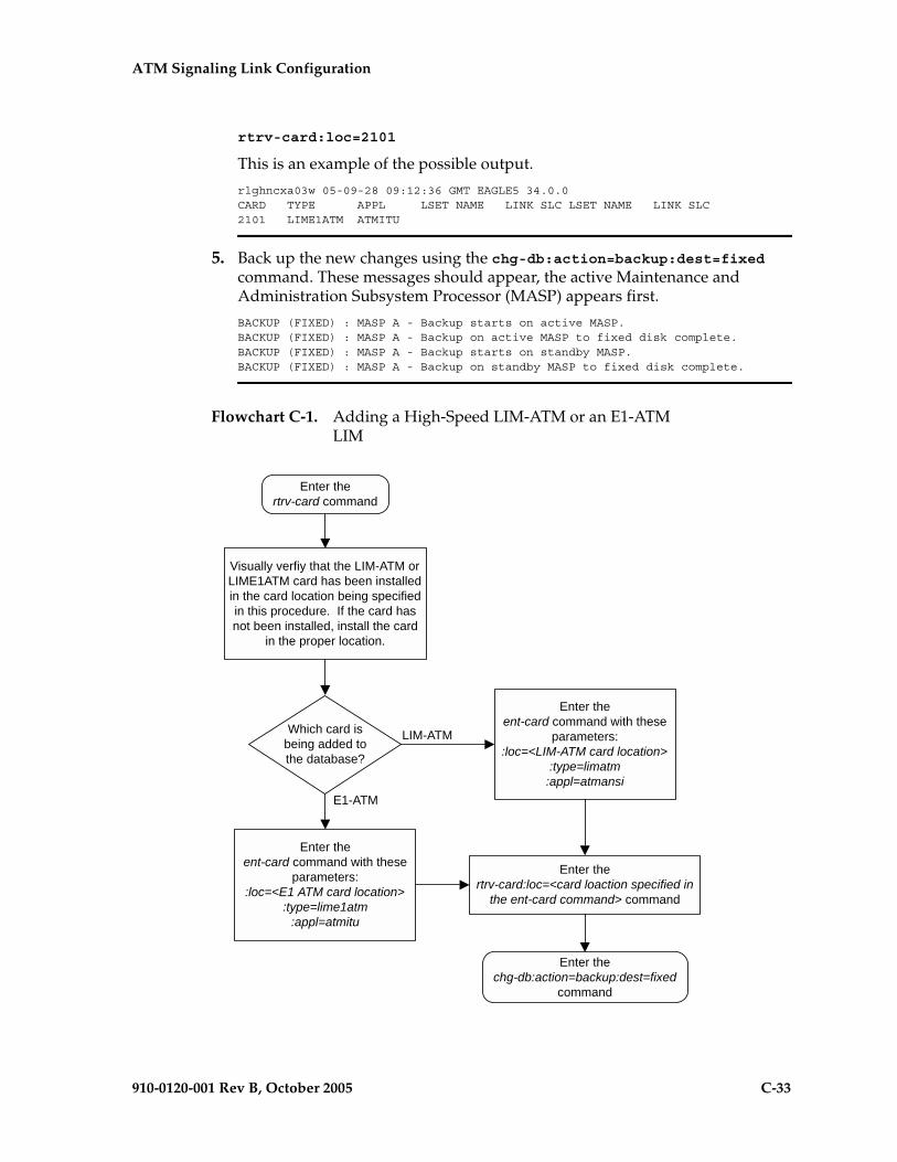
ATM Signaling Link Configuration
910-0120-001 Rev B, October 2005 C-33
rtrv-card:loc=2101
This is an example of the possible output.
rlghncxa03w 05-09-28 09:12:36 GMT EAGLE5 34.0.0CARD TYPE APPL LSET NAME LINK SLC LSET NAME LINK SLC2101 LIME1ATM ATMITU
5. Back up the new changes using the chg-db:action=backup:dest=fixed command. These messages should appear, the active Maintenance and Administration Subsystem Processor (MASP) appears first.
BACKUP (FIXED) : MASP A - Backup starts on active MASP.BACKUP (FIXED) : MASP A - Backup on active MASP to fixed disk complete.BACKUP (FIXED) : MASP A - Backup starts on standby MASP.BACKUP (FIXED) : MASP A - Backup on standby MASP to fixed disk complete.
Flowchart C-1. Adding a High-Speed LIM-ATM or an E1-ATM LIM
C-34 910-0120-001 Rev B, October 2005
ATM Signaling Link Configuration
Adding an ATM High-Speed Signaling Link
This procedure is used to add an ANSI ATM or E1 ATM high-speed signaling link to the database using the ent-slk command. The ent-slk command uses these parameters.
:loc – The card location of the LIM that the ATM high-speed signaling link will be assigned to. The cards specified by this parameter are LIM-ATM or LIME1ATM cards.
:link– The signaling link on the card specified in the loc parameter.
:lsn – The name of the linkset that will contain the signaling link.
:slc – The signaling link code. The SLC must be unique within the linkset. It must be the same at both the EAGLE 5 SAS location and the distant node.
:bps – The transmission rate for the link in bits per second.
:tset – Transmitter signal element timing
:lpset – link parameter set identifier – the ATM signaling parameter set. An ATM signaling link can be assigned to any of 30 parameter sets.
:atmtsel – ATM timing selector – The source of the timing for the ATM signaling link, internal, line, or external. Internal timing for an ANSI ATM signaling link is derived from an internal clock source operating at 1.544 MHz ± 50 ppm. For an E1 ATM signaling link, internal timing is derived from an internal clock source operating at 2.048 MHz ± 50 ppm. Line timing is derived from its received data stream, if present. External timing is derived from a clock source external to the EAGLE 5 SAS. Line timing is the default value for this parameter.
CAUTION: The atmtsel=internal parameter is only supported for lab use and not for live traffic.
NOTE: If the atmtsel=external parameter is specified with the ent-slk command, make sure that the correct TDM (P/N 870-0774-10 or later) is installed in card slots 1114 and 1116. Make sure that the external master clock source is connected to the EAGLE 5 SAS.
NOTE: To use an external high-speed master clock source other than RS-422, TDMs 870-0774-15 or later must be installed in card locations 1114 and 1116, and the TDM Global Timing Interface options must be configured. For more information, see the “Configuring the Options for the TDM Global Timing Interface” procedure on page 3-263.
:vci – virtual channel identifier – The identifier of the virtual channel used by the ATM signaling link for virtual channel connections.
:vpi – virtual path identifier – The identifier of the virtual path used by the ATM signaling link for virtual path connections.
:ll – The length of the cable used for the ANSI ATM signaling link. The value of the ll parameter is from 0 to 7, with each number representing a range of cable lengths, shown in Table C-11 on page C-35. The default value for this parameter is 0.

ATM Signaling Link Configuration
910-0120-001 Rev B, October 2005 C-35
:e1atmcrc4 – Specifies whether or not CRC4 is enabled on the E1 ATM high-speed signaling link.
:e1atmsi – Specifies the value of the two spare international bits of NFAS data, from 0 to 3 for the E1 ATM high-speed signaling link.
:e1atmsn – Specifies the value of the five spare national bits of NFAS data, from 0 to 31 for the E1 ATM high-speed signaling link.
The ent-slk command also contains these parameters: l2tset, l1mode, tset, ecm, pcrn1, pcrn2, ipliml2, ts, e1port, e1loc, t1port, and t1loc. These parameters are used only for configuring other types signaling links and are not used in this procedure. For more information on these signaling links, go to one of these sections:
• Low-speed and IP signaling links – “Adding an SS7 Signaling Link” on page 3-130
• E1 signaling links – Appendix A, “E1 Interface.”
• T1 signaling links – Appendix B, “T1 Interface.”
• X.25 signaling links – “Adding an X.25 Signaling Link” in the Database Administration Manual - Features.
These items must be configured in the database before an ATM high-speed signaling link can be added:
• Shelf – see “Adding a Shelf” in the Database Administration Manual - System Management
• Card – see “Adding a High-Speed LIM-ATM or an E1-ATM LIM” on page C-31
• Destination Point Code – see “Adding a Destination Point Code” on page 2-191
• Linkset – see “Adding an SS7 Linkset” on page 3-16.
Table C-11. ATM Signaling Link Cable Lengths
LL Parameter Value ATM Signaling Link Cable Length
0 0 to 110 feet
1 110 to 220 feet
2 220 to 330 feet
3 330 to 440 feet
4 440 to 550 feet
5 550 to 660 feet
6 more than 660 feet
7 used for external line buildout networks

C-36 910-0120-001 Rev B, October 2005
ATM Signaling Link Configuration
Verify that the link has been physically installed (all cable connections have been made).
To configure the EAGLE 5 SAS to perform circular routing detection test on the signaling links, “Configuring Circular Route Detection” procedure on page 3-231.
NOTE: Circular route detection is not supported in ITU networks.
To provision a EAGLE 5 SAS with more than 700 signaling links, the EAGLE 5 SAS must have certain levels of hardware installed. See the “Requirements for EAGLE 5 SASs Containing more than 700 Signaling Links” section on page D-2 for more information on these hardware requirements.
The EAGLE 5 SAS can contain a mixture of low-speed, E1, T1, ATM high-speed, and IP siganling links. The “Determining the Number of High-Speed and Low-Speed Signaling Links” section on page D-2 describes how to determine the quantities of the different types of signaling links the EAGLE 5 SAS can have.
ATM High-Speed Signaling Link Parameter Combinations
Table C-12 shows the parameter combinations that can be specified for ATM high-speed signaling links with the ent-slk command, and the parameters and values that can be used to provision each type of ATM high-speed signaling link.
Table C-12. ATM High-Speed Signaling Link Parameter Combinations
ATM (ANSI) High-Speed Signaling Link
E1 ATM High-Speed Signaling Link
Mandatory Parameters:loc = location of the LIM-ATM with the ATMANSI application
and the LIMATM card type.:loc = location of the E1 HSL card with the ATMITU
application and the LIME1ATM card type.
:link = A4 :link = A4
:lsn = linkset name 1 :lsn = linkset name 1, 2
:slc = 0 - 15 :slc = 0 - 15
Optional Parameters:bps = 1544000default value = 1544000
:bps = 2048000default value = 2048000
:lpset = 1 - 30default value = 1
:lpset = 1 - 30default value = 1
:atmtsel = line, internal, externaldefault value = line
:atmtsel = line, internal, externaldefault value = line
:vci = 0 - 65535 3
default value = 5:vci = 0 - 65535 3
default value = 5
:vpi = 0 - 4095default value = 0
:vpi = 0 - 4095default value = 0
:ll = 0 - 7default value = 0
:e1atmcrc4 = on, offdefault value = off:e1atmsi = 0 - 3default value = 3
:e1atmsn = 0 - 31default value = 0
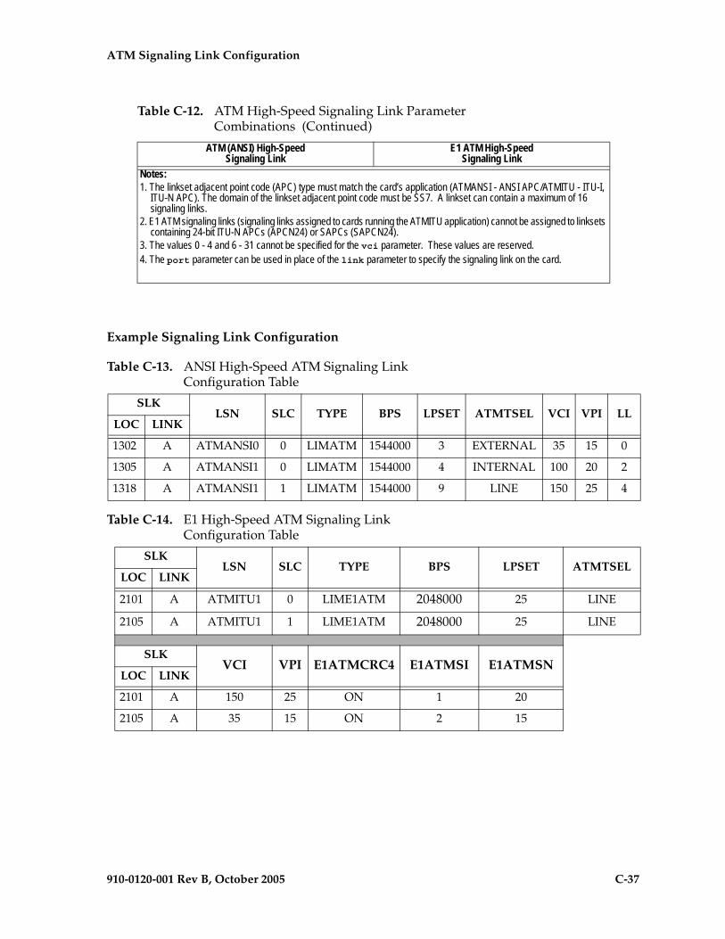
ATM Signaling Link Configuration
910-0120-001 Rev B, October 2005 C-37
Example Signaling Link Configuration
Notes:1. The linkset adjacent point code (APC) type must match the card’s application (ATMANSI - ANSI APC/ATMITU - ITU-I,
ITU-N APC). The domain of the linkset adjacent point code must be SS7. A linkset can contain a maximum of 16 signaling links.
2. E1 ATM signaling links (signaling links assigned to cards running the ATMITU application) cannot be assigned to linksets containing 24-bit ITU-N APCs (APCN24) or SAPCs (SAPCN24).
3. The values 0 - 4 and 6 - 31 cannot be specified for the vci parameter. These values are reserved.4. The port parameter can be used in place of the link parameter to specify the signaling link on the card.
Table C-13. ANSI High-Speed ATM Signaling Link Configuration Table
SLKLSN SLC TYPE BPS LPSET ATMTSEL VCI VPI LL
LOC LINK
1302 A ATMANSI0 0 LIMATM 1544000 3 EXTERNAL 35 15 0
1305 A ATMANSI1 0 LIMATM 1544000 4 INTERNAL 100 20 2
1318 A ATMANSI1 1 LIMATM 1544000 9 LINE 150 25 4
Table C-14. E1 High-Speed ATM Signaling Link Configuration Table
SLKLSN SLC TYPE BPS LPSET ATMTSEL
LOC LINK
2101 A ATMITU1 0 LIME1ATM 2048000 25 LINE
2105 A ATMITU1 1 LIME1ATM 2048000 25 LINE
SLKVCI VPI E1ATMCRC4 E1ATMSI E1ATMSN
LOC LINK
2101 A 150 25 ON 1 20
2105 A 35 15 ON 2 15
Table C-12. ATM High-Speed Signaling Link Parameter Combinations (Continued)
ATM (ANSI) High-Speed Signaling Link
E1 ATM High-Speed Signaling Link
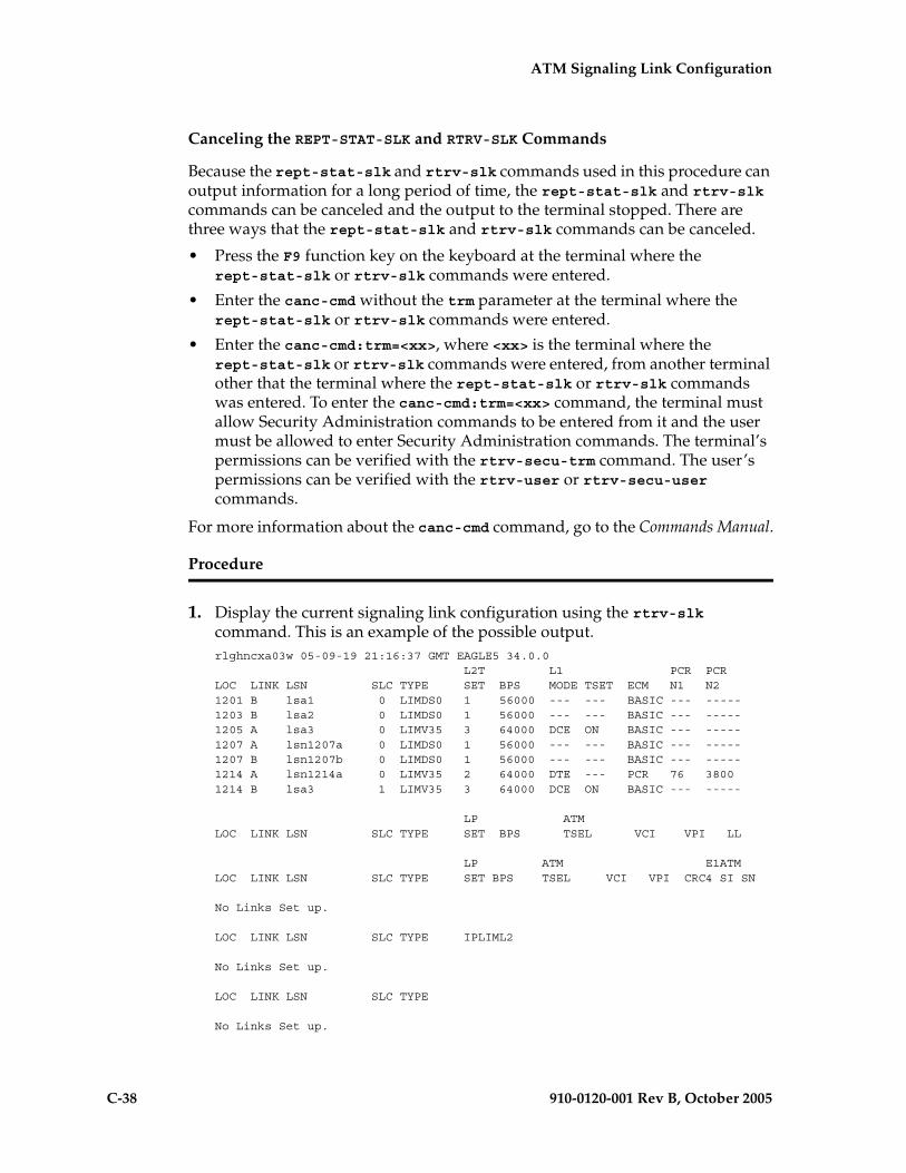
C-38 910-0120-001 Rev B, October 2005
ATM Signaling Link Configuration
Canceling the REPT-STAT-SLK and RTRV-SLK Commands
Because the rept-stat-slk and rtrv-slk commands used in this procedure can output information for a long period of time, the rept-stat-slk and rtrv-slk commands can be canceled and the output to the terminal stopped. There are three ways that the rept-stat-slk and rtrv-slk commands can be canceled.
• Press the F9 function key on the keyboard at the terminal where the rept-stat-slk or rtrv-slk commands were entered.
• Enter the canc-cmd without the trm parameter at the terminal where the rept-stat-slk or rtrv-slk commands were entered.
• Enter the canc-cmd:trm=<xx>, where <xx> is the terminal where the rept-stat-slk or rtrv-slk commands were entered, from another terminal other that the terminal where the rept-stat-slk or rtrv-slk commands was entered. To enter the canc-cmd:trm=<xx> command, the terminal must allow Security Administration commands to be entered from it and the user must be allowed to enter Security Administration commands. The terminal’s permissions can be verified with the rtrv-secu-trm command. The user’s permissions can be verified with the rtrv-user or rtrv-secu-user commands.
For more information about the canc-cmd command, go to the Commands Manual.
Procedure
1. Display the current signaling link configuration using the rtrv-slk command. This is an example of the possible output.rlghncxa03w 05-09-19 21:16:37 GMT EAGLE5 34.0.0 L2T L1 PCR PCRLOC LINK LSN SLC TYPE SET BPS MODE TSET ECM N1 N21201 B lsa1 0 LIMDS0 1 56000 --- --- BASIC --- -----1203 B lsa2 0 LIMDS0 1 56000 --- --- BASIC --- -----1205 A lsa3 0 LIMV35 3 64000 DCE ON BASIC --- -----1207 A lsn1207a 0 LIMDS0 1 56000 --- --- BASIC --- -----1207 B lsn1207b 0 LIMDS0 1 56000 --- --- BASIC --- -----1214 A lsn1214a 0 LIMV35 2 64000 DTE --- PCR 76 38001214 B lsa3 1 LIMV35 3 64000 DCE ON BASIC --- -----
LP ATMLOC LINK LSN SLC TYPE SET BPS TSEL VCI VPI LL
LP ATM E1ATMLOC LINK LSN SLC TYPE SET BPS TSEL VCI VPI CRC4 SI SN
No Links Set up.
LOC LINK LSN SLC TYPE IPLIML2
No Links Set up.
LOC LINK LSN SLC TYPE
No Links Set up.
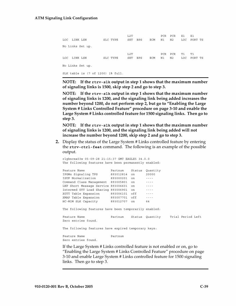
ATM Signaling Link Configuration
910-0120-001 Rev B, October 2005 C-39
L2T PCR PCR E1 E1LOC LINK LSN SLC TYPE SET BPS ECM N1 N2 LOC PORT TS
No Links Set up.
L2T PCR PCR T1 T1LOC LINK LSN SLC TYPE SET BPS ECM N1 N2 LOC PORT TS
No Links Set up.
SLK table is (7 of 1200) 1% full.
NOTE: If the rtrv-slk output in step 1 shows that the maximum number of signaling links is 1500, skip step 2 and go to step 3.
NOTE: If the rtrv-slk output in step 1 shows that the maximum number of signaling links is 1200, and the signaling link being added increases the number beyond 1200, do not perform step 2, but go to “Enabling the Large System # Links Controlled Feature” procedure on page 3-10 and enable the Large System # Links controlled feature for 1500 signaling links. Then go to step 3.
NOTE: If the rtrv-slk output in step 1 shows that the maximum number of signaling links is 1200, and the signaling link being added will not increase the number beyond 1200, skip step 2 and go to step 3.
2. Display the status of the Large System # Links controlled feature by entering the rtrv-ctrl-feat command. The following is an example of the possible output.
rlghncxa03w 05-09-28 21:15:37 GMT EAGLE5 34.0.0The following features have been permanently enabled:
Feature Name Partnum Status QuantityIPGWx Signaling TPS 893012814 on 20000ISUP Normalization 893000201 on ----Command Class Management 893005801 on ----LNP Short Message Service 893006601 on ----Intermed GTT Load Sharing 893006901 on ----XGTT Table Expansion 893006101 off ----XMAP Table Expansion 893007701 off ----HC-MIM SLK Capacity 893012707 on 64
The following features have been temporarily enabled:
Feature Name Partnum Status Quantity Trial Period LeftZero entries found.
The following features have expired temporary keys:
Feature Name PartnumZero entries found.
If the Large System # Links controlled feature is not enabled or on, go to “Enabling the Large System # Links Controlled Feature” procedure on page 3-10 and enable Large System # Links controlled feature for 1500 signaling links. Then go to step 3.

C-40 910-0120-001 Rev B, October 2005
ATM Signaling Link Configuration
3. Display the cards in the database using the rtrv-card command. This is an example of the possible output.rlghncxa03w 05-09-28 09:12:36 GMT EAGLE5 34.0.0CARD TYPE APPL LSET NAME LINK SLC LSET NAME LINK SLC1101 TSM SCCP 1102 TSM GLS 1103 DCM VXWSLAN 1113 GSPM EOAM1114 TDM-A1115 GSPM EOAM1116 TDM-B1117 MDAL1201 LIMDS0 SS7ANSI lsa1 B 01202 LIMV35 SS7ANSI 1203 LIMDS0 SS7ANSI lsa2 B 01204 LIMDS0 SS7ANSI 1205 LIMV35 SS7ANSI lsa3 A 0 1206 LIMV35 SS7ANSI 1207 LIMDS0 SS7ANSI lsn1207a A 0 lsn1207b B 01208 LIMDS0 SS7ANSI 1212 LIMV35 SS7ANSI 1213 LIMDS0 SS7ANSI 1214 LIMV35 SS7ANSI lsn1214a A 0 lsa3 B 11215 LIMDS0 SS7ANSI 1301 LIMV35 ATMANSI 1302 LIMATM ATMANSI 1304 LIMV35 SS7ANSI 1305 LIMATM ATMANSI 1308 LIMV35 SS7ANSI 1311 LIMDS0 SS7ANSI 1313 LIMDS0 SS7ANSI 1315 LIMV35 CCS7ITU 1317 LIMV35 CCS7ITU 1318 LIMATM ATMANSI
If the required ATM high-speed LIM is not in the database, perform the “Adding a High-Speed LIM-ATM or an E1-ATM LIM” procedure on page C-31 and add the ATM high-speed LIM to the database.
4. Display the current linkset configuration using the rtrv-ls command. This is an example of the possible output.
rlghncxa03w 05-09-10 11:43:04 GMT EAGLE5 34.0.0 L3T SLT GWS GWS GWSLSN APCA (SS7) SCRN SET SET BEI LST LNKS ACT MES DIS SLSCI NISe1e2 001-207-000 none 1 1 no B 6 off off off no offls1305 000-005-000 none 1 1 no A 1 off off off no offls1307 000-007-000 none 1 1 no A 1 off off off no offe1m1s1 001-001-001 none 1 1 no A 7 off off off no offe1m1s2 001-001-002 none 1 1 no A 7 off off off no off
L3T SLT GWS GWS GWSLSN APCA (X25) SCRN SET SET BEI LST LNKS ACT MES DIS SLSCI NIS
L3T SLT GWS GWS GWSLSN APCI (SS7) SCRN SET SET BEI LST LNKS ACT MES DIS SLSCI NISe1e2i 1-207-0 none 1 1 no B 4 off off off --- onls1315 0-015-0 none 1 1 no A 1 off off off --- offls1317 0-017-0 none 1 1 no A 1 off off off --- one1m2s1 1-011-1 none 1 1 no A 7 off off off --- off

ATM Signaling Link Configuration
910-0120-001 Rev B, October 2005 C-41
e1m2s2 1-011-2 none 1 1 no A 7 off off off --- off
L3T SLT GWS GWS GWSLSN APCN (SS7) SCRN SET SET BEI LST LNKS ACT MES DIS SLSCI NIS
L3T SLT GWS GWS GWSLSN APCN24 (SS7) SCRN SET SET BEI LST LNKS ACT MES DIS SLSCI NIS
L3T SLT GWS GWS GWSLSN (CHINA) APCN (SS7) SCRN SET SET BEI LST LNKS ACT MES DIS SLSCI NIS
L3T SLT GWS GWS GWSLSN (CHINA) APCN24 (SS7) SCRN SET SET BEI LST LNKS ACT MES DIS SLSCI NIS
Link set table is (10 of 1024) 1% full.
If the required linkset is not in the database, go to the “Adding an SS7 Linkset” procedure on page 3-17 and add the linkset to the database.
If you plan to use a linkset shown in this step, or a new linkset is being added in this step, skip step 5 and go to step 6.
NOTE: If an ANSI ATM high-speed signaling link is being added to the database, skip step 5 and go to step 6.
5. Display the linkset that the signaling link is being assigned to using the rtrv-ls command, specifying the name of the linkset that the signaling link is being assigned to. For this example, enter this command.
rtrv-ls:lsn=atmitu1
This is an example of the possible output.
rlghncxa03w 05-09-17 11:43:04 GMT EAGLE5 34.0.0
L3T SLT GWS GWS GWSLSN APCI (SS7) SCRN SET SET BEI LST LNKS ACT MES DIS SLSCI NISatmitu1 3-111-3 none 1 1 no A 0 off off off --- off
CLLI TFATCABMLQ MTPRSE ASL8 SLSRSB ITUTFR IPGWAPC ----------- 1 --- --- 1 off no
L2T L1 PCR PCR LOC LINK SLC TYPE SET BPS MODE TSET ECM N1 N2
LP ATM LOC LINK SLC TYPE SET BPS TSEL VCI VPI LL
LP ATM E1ATM LOC LINK SLC TYPE SET BPS TSEL VCI VPI CRC4 SI SN
LOC LINK SLC TYPE IPLIML2
LOC LINK SLC TYPE
L2T PCR PCR E1 E1 LOC LINK SLC TYPE SET BPS ECM N1 N2 LOC PORT TS
L2T PCR PCR T1 T1 LOC LINK SLC TYPE SET BPS ECM N1 N2 LOC PORT TS

C-42 910-0120-001 Rev B, October 2005
ATM Signaling Link Configuration
SAPCN 1234-aa 1235-bb 1200-zz
Link set table is (13 of 1024) 1% full.
Linksets containing 24-bit ITU-N adjacent point codes (APCN24) or secondary adjacent point codes (SAPCN24) cannot be assigned to a E1 ATM high-speed signaling link. Go back to step 4 and choose another linkset, or go to the “Adding an SS7 Linkset” procedure on page 3-17 and add the linkset to the database that does not contain either a 24-bit ITU-N APC or SAPC.
6. Display the existing values for the ATM link parameter set that will be assigned to the signaling link using the rtrv-atm-lps command specifying the link parameter set. For this example, enter this command.
rtrv-atm-lps:lpset=25
This is an example of the possible output.rlghncxa03w 05-09-28 16:02:05 GMT EAGLE5 34.0.0ATM LINK PARAMETER SET TIMERS AND PARAMETERS (TIMERS IN SECONDS) SSCOP PARAMETERS TMR TMR TMR TMR TMRLPSET MAXCC MAXPD MAXSTAT CC KALIVE NORSP POLL IDLE25 4 500 67 0.2 0.125 1.5 0.150 0.125
SSCF-NNI PARAMETERS TMRT1 TMRT2 TMRT3 N1 05.0 30.0 0.000925 1000
SAAL PARAMETERS MAX TMR TNRNO TMR N TMR NRP SREC CRED ERM BLK PROV 0 3600 1.5 0.125 3 0600.0
NONCONFIGURABLE PARAMETERS SDU UU FC FC SIZE SIZE N NR BC TSUP TLOSS ERMSM THRES 272 4 9 -- -- 120 1.3 0.1 0.244
If you wish to change the values in this ATM parameter set, go to the “Changing an ATM High-Speed Signaling Link Parameter Set” procedure on page C-50.
CAUTION: Changing the values in this ATM link parameter set will impact the performance of all the signaling links using this ATM parameter set.
7. Add the signaling link to the database using the ent-slk command. Use Table C-12 on page C-36 as a guide for the parameters that can be specified with the ent-slk command. For this example, enter these commands.
ent-slk:loc=1302:link=a:lsn=atmansi0:slc=0:bps=1544000:lpset=3:atmtsel=external:vci=35:vpi=15:ll=0
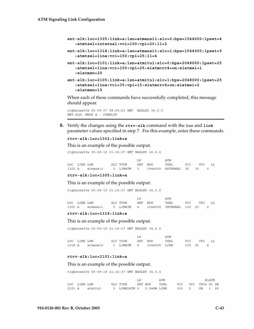
ATM Signaling Link Configuration
910-0120-001 Rev B, October 2005 C-43
ent-slk:loc=1305:link=a:lsn=atmansi1:slc=0:bps=1544000:lpset=4:atmtsel=internal:vci=100:vpi=20:ll=2
ent-slk:loc=1318:link=a:lsn=atmansi1:slc=1:bps=1544000:lpset=9:atmtsel=line:vci=150:vpi=25:ll=4
ent-slk:loc=2101:link=a:lsn=atmitu1:slc=0:bps=2048000:lpset=25:atmtsel=line:vci=150:vpi=25:e1atmcrc4=on:e1atmsi=1:e1atmsn=20
ent-slk:loc=2105:link=a:lsn=atmitu1:slc=1:bps=2048000:lpset=25:atmtsel=line:vci=35:vpi=15:e1atmcrc4=on:e1atmsi=2:e1atmsn=15
When each of these commands have successfully completed, this message should appear.
rlghncxa03w 05-09-07 08:29:03 GMT EAGLE5 34.0.0ENT-SLK: MASP A - COMPLTD
8. Verify the changes using the rtrv-slk command with the loc and link parameter values specified in step 7. For this example, enter these commands.
rtrv-slk:loc=1302:link=a
This is an example of the possible output.rlghncxa03w 05-09-19 21:16:37 GMT EAGLE5 34.0.0
LP ATMLOC LINK LSN SLC TYPE SET BPS TSEL VCI VPI LL1302 A atmansi0 0 LIMATM 3 1544000 EXTERNAL 35 15 0
rtrv-slk:loc=1305:link=a
This is an example of the possible output.
rlghncxa03w 05-09-19 21:16:37 GMT EAGLE5 34.0.0
LP ATMLOC LINK LSN SLC TYPE SET BPS TSEL VCI VPI LL1305 A atmansi1 0 LIMATM 4 1544000 INTERNAL 100 20 2
rtrv-slk:loc=1318:link=a
This is an example of the possible output.
rlghncxa03w 05-09-19 21:16:37 GMT EAGLE5 34.0.0
LP ATMLOC LINK LSN SLC TYPE SET BPS TSEL VCI VPI LL1318 A atmansi0 1 LIMATM 9 1544000 LINE 150 25 4
rtrv-slk:loc=2101:link=a
This is an example of the possible output.
rlghncxa03w 05-09-19 21:16:37 GMT EAGLE5 34.0.0
LP ATM E1ATMLOC LINK LSN SLC TYPE SET BPS TSEL VCI VPI CRC4 SI SN2101 A atmitu1 0 LIME1ATM 5 2.048M LINE 150 2 ON 1 20

C-44 910-0120-001 Rev B, October 2005
ATM Signaling Link Configuration
rtrv-slk:loc=2105:link=a
This is an example of the possible output.
rlghncxa03w 05-09-19 21:16:37 GMT EAGLE5 34.0.0
LP ATM E1ATMLOC LINK LSN SLC TYPE SET BPS TSEL VCI VPI CRC4 SI SN2105 A atmitu1 1 LIME1ATM 5 2.048M LINE 35 15 ON 2 15
9. If the signaling link added in step 7 was the first signaling link assigned to the card, that card must be brought into service with the rst-card command, specifying the location of the card. For this example, enter these commands.
rst-card:loc=1302
rst-card:loc=1305
rst-card:loc=1318
rst-card:loc=2101
rst-card:loc=2105
When each of these commands have successfully completed, this message should appear.
rlghncxa03w 05-09-23 13:05:05 GMT EAGLE5 34.0.0Card has been allowed.
10. Activate all signaling links on the cards using the act-slk command, specifying the card location and signaling link specified in step 7. For this example, enter these commands.act-slk:loc=1302:link=a
act-slk:loc=1305:link=a
act-slk:loc=1318:link=a
act-slk:loc=2101:link=a
act-slk:loc=2105:link=a
When each of these commands have successfully completed, this message should appear.rlghncxa03w 05-09-07 08:31:24 GMT EAGLE5 34.0.0Activate Link message sent to card
11. Check the status of the signaling links added in step 7 using the rept-stat-slk command with the loc and link parameter values specified in step 7. The state of each signaling link should be in service normal (IS-NR) after the link has completed alignment (shown in the PST field). For this example, enter these commands.
rept-stat-slk:loc=1302:link=a
This is an example of the possible output.
rlghncxa03w 05-09-19 21:16:37 GMT EAGLE5 34.0.0SLK LSN CLLI PST SST AST1302,A atmansi0 ----------- IS-NR Avail ---- ALARM STATUS = No Alarms
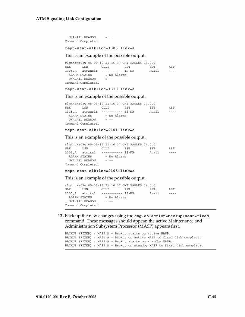
ATM Signaling Link Configuration
910-0120-001 Rev B, October 2005 C-45
UNAVAIL REASON = --Command Completed.
rept-stat-slk:loc=1305:link=a
This is an example of the possible output.
rlghncxa03w 05-09-19 21:16:37 GMT EAGLE5 34.0.0SLK LSN CLLI PST SST AST1305,A atmansi1 ----------- IS-NR Avail ---- ALARM STATUS = No Alarms UNAVAIL REASON = --Command Completed.
rept-stat-slk:loc=1318:link=a
This is an example of the possible output.
rlghncxa03w 05-09-19 21:16:37 GMT EAGLE5 34.0.0SLK LSN CLLI PST SST AST1318,A atmansi1 ----------- IS-NR Avail ---- ALARM STATUS = No Alarms UNAVAIL REASON = --Command Completed.
rept-stat-slk:loc=2101:link=a
This is an example of the possible output.
rlghncxa03w 05-09-19 21:16:37 GMT EAGLE5 34.0.0SLK LSN CLLI PST SST AST2101,A atmitu1 ----------- IS-NR Avail ---- ALARM STATUS = No Alarms UNAVAIL REASON = --Command Completed.
rept-stat-slk:loc=2105:link=a
This is an example of the possible output.
rlghncxa03w 05-09-19 21:16:37 GMT EAGLE5 34.0.0SLK LSN CLLI PST SST AST2105,A atmitu1 ----------- IS-NR Avail ---- ALARM STATUS = No Alarms UNAVAIL REASON = --Command Completed.
12. Back up the new changes using the chg-db:action=backup:dest=fixed command. These messages should appear, the active Maintenance and Administration Subsystem Processor (MASP) appears first.
BACKUP (FIXED) : MASP A - Backup starts on active MASP.BACKUP (FIXED) : MASP A - Backup on active MASP to fixed disk complete.BACKUP (FIXED) : MASP A - Backup starts on standby MASP.BACKUP (FIXED) : MASP A - Backup on standby MASP to fixed disk complete.

C-46 910-0120-001 Rev B, October 2005
ATM Signaling Link Configuration
Flowchart C-2. Adding an ATM High-Speed Signaling Link (Sheet 1 of 4)

ATM Signaling Link Configuration
910-0120-001 Rev B, October 2005 C-47
Flowchart C-2. Adding an ATM High-Speed Signaling Link (Sheet 2 of 4)
Is the required cardin the database?
Yes
No
Enter thertrv-card command
Go to the "Adding a High-SpeedLIM-ATM or an E1-ATM LIM"
procedure and add the LIM-ATMor E1 ATM LIM to the database
FromSheet 1
Enter the rtrv-lscommand
Is the desiredlinkset in thedatabase?
Yes
No
Enter thertrv-ls:lsn=<axxxxxxx>
command where<axxxxxxx> is the name ofthe linkset that the signaling
link is being assigned to.
ToSheet 3
Go to the "Adding an SS7Linkset" procedure in Chapter 3,
"SS7 Configuration," and addthe linkset to the database
What applicationis assigned to the card
that the ATM high-speedsignaling link will be
assigned to?
ATMITU ATMANSI
Does the linksetcontain a 24-bit ITU-N
APC (APCN24) or SAPC(SPCN24)?
Yes
A signaling link assigned to a card runningthe ATMITU application cannot be assigned
to a linkset with a 24-bit ITU-N APC orSAPC. Either choose another linkset fromthe rtrv-ls output, or go to the "Adding an
SS7 Linkset" procedure in Chapter 3, "SS7Configuration," and add a linkset to thedatabase that does not contain a 24-bit
ITU-N APC or SACP.No
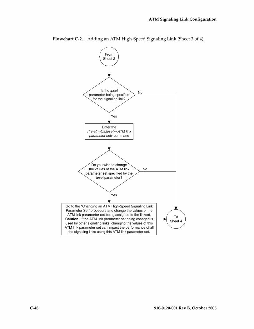
C-48 910-0120-001 Rev B, October 2005
ATM Signaling Link Configuration
Flowchart C-2. Adding an ATM High-Speed Signaling Link (Sheet 3 of 4)
FromSheet 2
Is the lpsetparameter being specified
for the signaling link?
No
Yes
Go to the "Changing an ATM High-Speed Signaling LinkParameter Set" procedure and change the values of theATM link paramerter set being assigned to the linkset.
Caution: If the ATM link parameter set being changed isused by other signaling links, changing the values of thisATM link parameter set can impact the performance of all
the signaling links using this ATM link parameter set.
ToSheet 4
Do you wish to changethe values of the ATM link
parameter set specified by thelpset parameter?
Enter thertrv-atm-lps:lpset=<ATM linkparameter set> command
Yes
No

ATM Signaling Link Configuration
910-0120-001 Rev B, October 2005 C-49
Flowchart C-2. Adding an ATM High-Speed Signaling Link (Sheet 4 of 4)
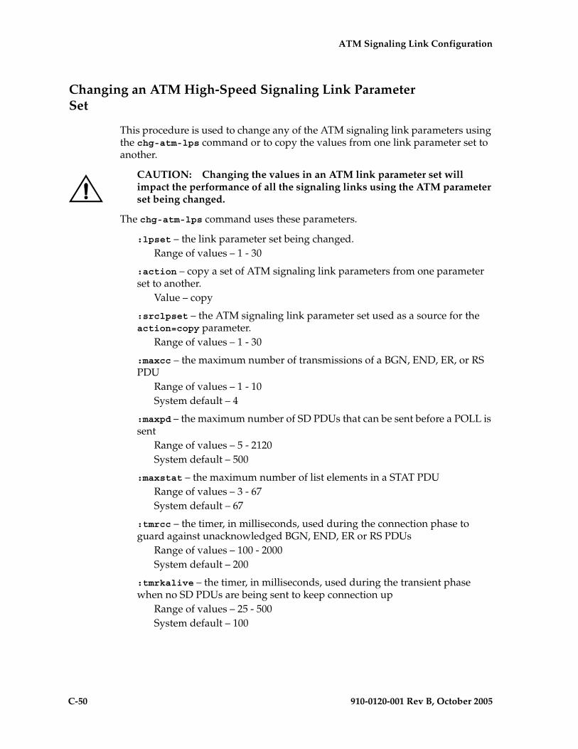
C-50 910-0120-001 Rev B, October 2005
ATM Signaling Link Configuration
Changing an ATM High-Speed Signaling Link Parameter Set
This procedure is used to change any of the ATM signaling link parameters using the chg-atm-lps command or to copy the values from one link parameter set to another.
CAUTION: Changing the values in an ATM link parameter set will impact the performance of all the signaling links using the ATM parameter set being changed.
The chg-atm-lps command uses these parameters.
:lpset – the link parameter set being changed.Range of values – 1 - 30
:action – copy a set of ATM signaling link parameters from one parameter set to another.
Value – copy
:srclpset – the ATM signaling link parameter set used as a source for the action=copy parameter.
Range of values – 1 - 30
:maxcc – the maximum number of transmissions of a BGN, END, ER, or RS PDU
Range of values – 1 - 10System default – 4
:maxpd – the maximum number of SD PDUs that can be sent before a POLL is sent
Range of values – 5 - 2120System default – 500
:maxstat – the maximum number of list elements in a STAT PDURange of values – 3 - 67System default – 67
:tmrcc – the timer, in milliseconds, used during the connection phase to guard against unacknowledged BGN, END, ER or RS PDUs
Range of values – 100 - 2000System default – 200
:tmrkalive – the timer, in milliseconds, used during the transient phase when no SD PDUs are being sent to keep connection up
Range of values – 25 - 500System default – 100
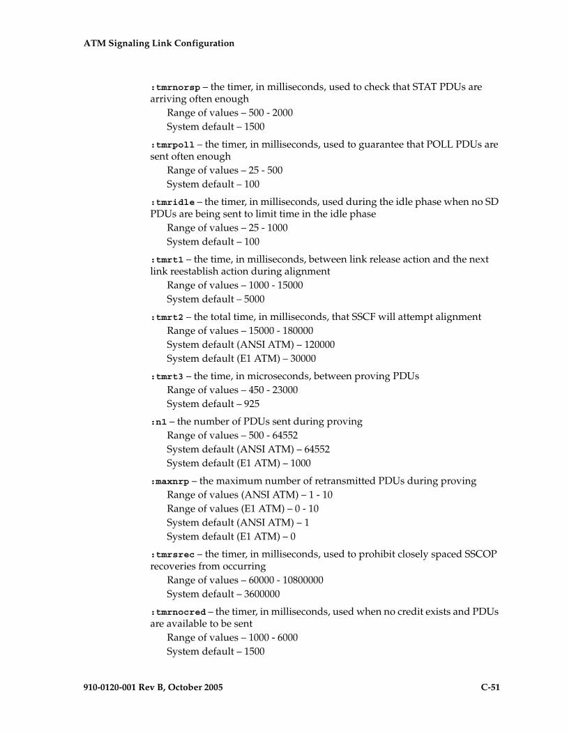
ATM Signaling Link Configuration
910-0120-001 Rev B, October 2005 C-51
:tmrnorsp – the timer, in milliseconds, used to check that STAT PDUs are arriving often enough
Range of values – 500 - 2000System default – 1500
:tmrpoll – the timer, in milliseconds, used to guarantee that POLL PDUs are sent often enough
Range of values – 25 - 500System default – 100
:tmridle – the timer, in milliseconds, used during the idle phase when no SD PDUs are being sent to limit time in the idle phase
Range of values – 25 - 1000System default – 100
:tmrt1 – the time, in milliseconds, between link release action and the next link reestablish action during alignment
Range of values – 1000 - 15000System default – 5000
:tmrt2 – the total time, in milliseconds, that SSCF will attempt alignmentRange of values – 15000 - 180000System default (ANSI ATM) – 120000System default (E1 ATM) – 30000
:tmrt3 – the time, in microseconds, between proving PDUsRange of values – 450 - 23000System default – 925
:n1 – the number of PDUs sent during provingRange of values – 500 - 64552System default (ANSI ATM) – 64552System default (E1 ATM) – 1000
:maxnrp – the maximum number of retransmitted PDUs during provingRange of values (ANSI ATM) – 1 - 10Range of values (E1 ATM) – 0 - 10System default (ANSI ATM) – 1System default (E1 ATM) – 0
:tmrsrec – the timer, in milliseconds, used to prohibit closely spaced SSCOP recoveries from occurring
Range of values – 60000 - 10800000System default – 3600000
:tmrnocred – the timer, in milliseconds, used when no credit exists and PDUs are available to be sent
Range of values – 1000 - 6000System default – 1500
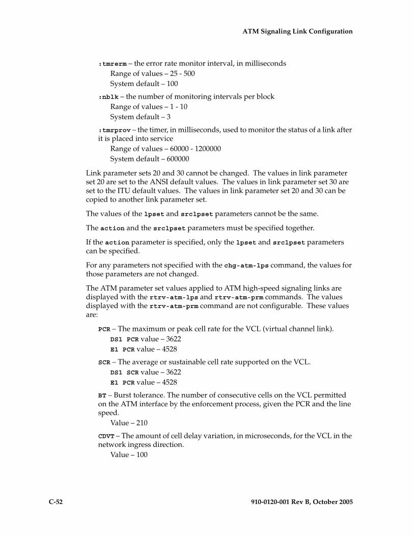
C-52 910-0120-001 Rev B, October 2005
ATM Signaling Link Configuration
:tmrerm – the error rate monitor interval, in millisecondsRange of values – 25 - 500System default – 100
:nblk – the number of monitoring intervals per blockRange of values – 1 - 10System default – 3
:tmrprov – the timer, in milliseconds, used to monitor the status of a link after it is placed into service
Range of values – 60000 - 1200000System default – 600000
Link parameter sets 20 and 30 cannot be changed. The values in link parameter set 20 are set to the ANSI default values. The values in link parameter set 30 are set to the ITU default values. The values in link parameter set 20 and 30 can be copied to another link parameter set.
The values of the lpset and srclpset parameters cannot be the same.
The action and the srclpset parameters must be specified together.
If the action parameter is specified, only the lpset and srclpset parameters can be specified.
For any parameters not specified with the chg-atm-lps command, the values for those parameters are not changed.
The ATM parameter set values applied to ATM high-speed signaling links are displayed with the rtrv-atm-lps and rtrv-atm-prm commands. The values displayed with the rtrv-atm-prm command are not configurable. These values are:
PCR – The maximum or peak cell rate for the VCL (virtual channel link).DS1 PCR value – 3622E1 PCR value – 4528
SCR – The average or sustainable cell rate supported on the VCL.DS1 SCR value – 3622E1 PCR value – 4528
BT – Burst tolerance. The number of consecutive cells on the VCL permitted on the ATM interface by the enforcement process, given the PCR and the line speed.
Value – 210
CDVT – The amount of cell delay variation, in microseconds, for the VCL in the network ingress direction.
Value – 100
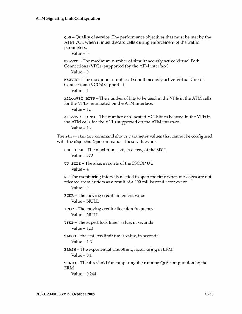
ATM Signaling Link Configuration
910-0120-001 Rev B, October 2005 C-53
QoS – Quality of service. The performance objectives that must be met by the ATM VCL when it must discard cells during enforcement of the traffic parameters.
Value – 3
MaxVPC – The maximum number of simultaneously active Virtual Path Connections (VPCs) supported (by the ATM interface).
Value – 0
MAXVCC – The maximum number of simultaneously active Virtual Circuit Connections (VCCs) supported.
Value – 1
AllocVPI BITS – The number of bits to be used in the VPIs in the ATM cells for the VPLs terminated on the ATM interface.
Value – 12
AllocVCI BITS – The number of allocated VCI bits to be used in the VPIs in the ATM cells for the VCLs supported on the ATM interface.
Value – 16.
The rtrv-atm-lps command shows parameter values that cannot be configured with the chg-atm-lps command. These values are:
SDU SIZE – The maximum size, in octets, of the SDUValue – 272
UU SIZE – The size, in octets of the SSCOP UUValue – 4
N – The monitoring intervals needed to span the time when messages are not released from buffers as a result of a 400 millisecond error event.
Value – 9
FCNR – The moving credit increment valueValue – NULL
FCBC – The moving credit allocation frequencyValue – NULL
TSUP – The superblock timer value, in secondsValue – 120
TLOSS – the stat loss limit timer value, in secondsValue – 1.3
ERMSM – The exponential smoothing factor using in ERMValue – 0.1
THRES – The threshold for comparing the running QoS computation by the ERM
Value – 0.244

C-54 910-0120-001 Rev B, October 2005
ATM Signaling Link Configuration
For this example, the values ATM link parameter set 5 are being changed to these values.
maxcc = 8 PDUs
maxpd = 2000 PDUs
maxstat = 45 PDUs
tmrcc = 1500 milliseconds
tmrkalive = 500 milliseconds
tmrnorsp = 1000 milliseconds
tmrt1 = 10000 milliseconds
tmrt2 = 19000 milliseconds
tmrt3 = 3000 microseconds
n1 = 10000 PDUs
maxnrp = 7 attempt
tmrsrec = 750000 milliseconds
nblk = 6 monitoring intervals per block
Procedure
1. Display the existing values for the ATM link parameter set being changed using the rtrv-atm-lps command specifying the link parameter set being changed. For this example, enter this command.
rtrv-atm-lps:lpset=5
This is an example of the possible output.
rlghncxa03w 05-09-28 16:02:05 GMT EAGLE5 34.0.0ATM LINK PARAMETER SET TIMERS AND PARAMETERS (REAL NUMBERS IN SECONDS) SSCOP PARAMETERS TMR TMR TMR TMR TMRLPSET MAXCC MAXPD MAXSTAT CC KALIVE NORSP POLL IDLE5 4 500 67 0.2 0.1 1.5 0.1 0.1
SSCF-NNI PARAMETERS TMRT1 TMRT2 TMRT3 N1 05.0 120.0 0.000925 64552
SAAL PARAMETERS MAX TMR TNRNO TMR N TMR NRP SREC CRED ERM BLK PROV 1 3600.0 1.5 0.1 3 0600.0
NONCONFIGURABLE PARAMETERS SDU UU FC FC SIZE SIZE N NR BC TSUP TLOSS ERMSM THRES 272 4 9 -- -- 120 1.3 0.1 0.244

ATM Signaling Link Configuration
910-0120-001 Rev B, October 2005 C-55
2. Change the values of the ATM link parameter set with the chg-atm-lps command specifying the link parameter set. For this example, enter this command.
chg-atm-lps:lpset=5:maxcc=8:maxpd=2000:maxstat=45:tmrcc=1500:tmrkalive=500:tmrnorsp=1000:tmrt1=10000:tmrt2=19000:tmrt3=3000:n1=10000:maxnrp=7:tmrsrec=750000:nblk=6
This message should appear.
rlghncxa03w 05-09-28 00:22:57 GMT EAGLE5 34.0.0CHG-ATM-LPS: MASP A - COMPLTD
3. Verify the changes using the rtrv-atm-lps command and the link parameter set specified in step 2. For this example, enter this command.
rtrv-atm-lps:lpset=5
This is an example of the possible output.
rlghncxa03w 05-09-28 16:02:05 GMT EAGLE5 34.0.0ATM LINK PARAMETER SET TIMERS AND PARAMETERS (REAL NUMBERS IN SECONDS) SSCOP PARAMETERS TMR TMR TMR TMR TMRLPSET MAXCC MAXPD MAXSTAT CC KALIVE NORSP POLL IDLE5 8 2000 45 1.5 0.5 1.0 0.1 0.1
SSCF-NNI PARAMETERS TMRT1 TMRT2 TMRT3 N1 10.0 019.0 0.003000 10000
SAAL PARAMETERS MAX TMR TNRNO TMR N TMR NRP SREC CRED ERM BLK PROV 7 0750.0 1.5 0.1 6 0600.0
NONCONFIGURABLE PARAMETERS SDU UU FC FC SIZE SIZE N NR BC TSUP TLOSS ERMSM THRES 272 4 9 -- -- 120 1.3 0.1 0.244
4. Back up the new changes using the chg-db:action=backup:dest=fixed command. These messages should appear, the active Maintenance and Administration Subsystem Processor (MASP) appears first.
BACKUP (FIXED) : MASP A - Backup starts on active MASP.BACKUP (FIXED) : MASP A - Backup on active MASP to fixed disk complete.BACKUP (FIXED) : MASP A - Backup starts on standby MASP.BACKUP (FIXED) : MASP A - Backup on standby MASP to fixed disk complete.

C-56 910-0120-001 Rev B, October 2005
ATM Signaling Link Configuration
Flowchart C-3. Changing an ATM High-Speed Signaling Link Parameter Set
Enter the rtrv-atm-lps:lpset=<parameter set being
changed> command
No
YesAre the actionand srclpset parameters
being used?
Enter thechg-db:action=backup:dest=fixed
command
Enter the chg-atm-lps command withthese parameters:
:lpset=<parameter set being changed>:action=copy
:srclpset=<parameter set being copied>
Enter the chg-atm-lps command with thelpset=<parameter set being changed>
parameter, without the action=copy andsrclpset parameters, and with at least one
of the remaining optional parameters.
Enter the rtrv-atm-lps:lpset=<parameter set thatwas changed> command

910-0120-001 Rev B, October 2005 D-1
D
Reference Information
Requirements for Systems Containing more than 700 Signaling Links ...................................................................................D-2
Determining the Number of High-Speed and Low-Speed Signaling Links............................................................................................................D-2

D-2 910-0120-001 Rev B, October 2005
Reference Information
Requirements for EAGLE 5 SASs Containing more than 700 Signaling Links
To provision a EAGLE 5 SAS with more than 700 signaling links (currently the EAGLE 5 SAS can have maximum capacities of 1200 or 1500 signaling links), the following additional requirements must be met:
• The Measurements Platform feature must be enabled. Perform these procedures in the Database Administration Manual - System Management to enable the Measurements Platform Feature:
– “Adding an MCPM”
– “Configuring the IP Communications Link for the Measurements Platform Feature”
– “Adding an FTP Server”
• To provision more than 1200 signaling links, the Large System # Links controlled feature must be enabled for 1500 signaling links. For more information on enabling this feature, go to “Enabling the Large System # Links Controlled Feature” procedure on page 3-10.
Determining the Number of High-Speed and Low-Speed Signaling Links
The EAGLE 5 SAS contain either a maximum of 1200 or 1500 signaling links, depending the hardware that is installed. The method of determining the number of high-speed and low-speed signaling links that can be in the EAGLE 5 SAS is shown in the next section.
An EAGLE 5 SAS containing either 1200 or 1500 signaling links can contain the following quantities of signaling links:
• 1200 low-speed signaling links
• 115 high-speed ATM signaling links (signaling links assigned to either ATMANSI or ATMITU applications)
• 100 signaling links assigned to either the IPLIM or IPLIMI applications.
• 64 signaling links assigned to single-slot ADMs running either the ss7ipgw or ipgwi application, or combinations of the ss7ipgw and ipgwi applications. If DCMs are present in the EAGLE 5 SAS, there can be a maximum of 2 signaling links assigned to the ss7ipgw application and 2 signaling links assigned to the ipgwi application.
Table D-1 shows the combinations of high-speed signaling links and low-speed signaling links allowed in the EAGLE 5 SAS.

Reference Information
910-0120-001 Rev B, October 2005 D-3
Table D-1. Number of High-Speed and Low-Speed Links Supported at 100% Traffic
Number of High-Speed ATM Signaling Links
Number of Low-Speed
Signaling Links
Number of IP Signaling Links
Number of Low-Speed
Signaling Links
0 1500 0 1500
0 1200 0 1200
1 1199 1 1199
5 1195 5 1195
15 1185 15 1185
20 1180 20 1180
30 1165 30 1165
40 1150 40 1040
60 1110 60 880
80 1025 80 720
90 950 90 560
100 875 100 400
115 800

D-4 910-0120-001 Rev B, October 2005
Reference Information
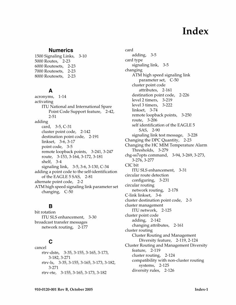
910-0120-001 Rev B, October 2005 Index-1
Numerics1500 Signaling Links, 3-105000 Routes, 2-236000 Routesets, 2-237000 Routesets, 2-238000 Routesets, 2-23
Aacronyms, 1-14activating
ITU National and International Spare Point Code Support feature, 2-42, 2-51
addingcard, 3-5, C-31cluster point code, 2-142destination point code, 2-191linkset, 3-6, 3-17point code, 3-5remote loopback points, 3-241, 3-247route, 3-153, 3-164, 3-172, 3-181shelf, 3-4signaling link, 3-5, 3-6, 3-130, C-34
adding a point code to the self-identification of the EAGLE 5 SAS, 2-81
alternate point code, 2-2ATM high speed signaling link parameter set
changing, C-50
Bbit rotation
ITU SLS enhancement, 3-30broadcast transfer messages
network routing, 2-177
Ccancel
rtrv-dstn, 3-35, 3-155, 3-165, 3-173, 3-182, 3-271
rtrv-ls, 3-35, 3-155, 3-165, 3-173, 3-182, 3-271
rtrv-rte, 3-155, 3-165, 3-173, 3-182
cardadding, 3-5
card typesignaling link, 3-5
changingATM high speed signaling link
parameter set, C-50cluster point code
attributes, 2-161destination point code, 2-226level 2 timers, 3-219level 3 timers, 3-222linkset, 3-74remote loopback points, 3-250route, 3-206self identification of the EAGLE 5
SAS, 2-90signaling link test message, 3-228
Changing the DPC Quantity, 2-23Changing the HC MIM Temperature Alarm
Thresholds, 3-279chg-ss7opts command, 3-94, 3-269, 3-273,
3-276, 3-277CIC bit
ITU SLS enhancement, 3-31circular route detection
configuring, 3-231circular routing
network routing, 2-178C-link linkset, 3-6cluster destination point code, 2-3cluster management
ITU network, 2-125cluster point code
adding, 2-142changing attributes, 2-161
cluster routingCluster Routing and Management
Diversity feature, 2-119, 2-124Cluster Routing and Management Diversity
feature, 2-119cluster routing, 2-124compatibility with non-cluster routing
systems, 2-125diversity rules, 2-126
Index
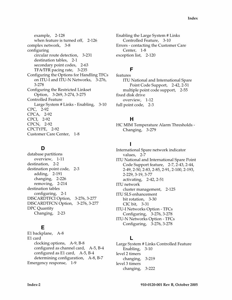
Index-2 910-0120-001 Rev B, October 2005
Index
example, 2-128when feature is turned off, 2-126
complex network, 3-8configuring
circular route detection, 3-231destination tables, 2-1secondary point codes, 2-63TFA⁄TFR pacing rate, 3-235
Configuring the Options for Handling TFCs on ITU-I and ITU-N Networks, 3-276, 3-278
Configuring the Restricted Linkset Option, 3-269, 3-274, 3-275
Controlled FeatureLarge System # Links - Enabling, 3-10
CPC, 2-92CPCA, 2-92CPCI, 2-92CPCN, 2-92CPCTYPE, 2-92Customer Care Center, 1-8
Ddatabase partitions
overview, 1-11destination, 2-2destination point code, 2-3
adding, 2-191changing, 2-226removing, 2-214
destination tablesconfiguring, 2-1
DISCARDTFCI Option, 3-276, 3-277DISCARDTFCN Option, 3-276, 3-277DPC Quantity
Changing, 2-23
EE1 backplane, A-8E1 card
clocking options, A-9, B-8configured as channel card, A-5, B-4configured as E1 card, A-5, B-4determining configuration, A-8, B-7
Emergency response, 1-9
Enabling the Large System # Links Controlled Feature, 3-10
Errors - contacting the Customer Care Center, 1-8
exception list, 2-120
Ffeatures
ITU National and International Spare Point Code Support, 2-42, 2-51
multiple point code support, 2-55fixed disk drive
overview, 1-12full point code, 2-3
HHC MIM Temperature Alarm Thresholds -
Changing, 3-279
IInternational Spare network indicator
values, 2-7ITU National and International Spare Point
Code Support feature, 2-7, 2-43, 2-44, 2-49, 2-50, 2-83, 2-85, 2-91, 2-100, 2-193, 2-229, 3-19, 3-77activating, 2-42, 2-51
ITU networkcluster management, 2-125
ITU SLS enhancementbit rotation, 3-30CIC bit, 3-31
ITU-I Networks Option - TFCsConfiguring, 3-276, 3-278
ITU-N Networks Option - TFCsConfiguring, 3-276, 3-278
LLarge System # Links Controlled Feature
Enabling, 3-10level 2 timers
changing, 3-219level 3 timers
changing, 3-222
Index
910-0120-001 Rev B, October 2005 Index-3
linksetadding, 3-6, 3-17changing, 3-74removing, 3-63route, 3-7
linksets, 3-3local link congestion
network routing, 2-177LSRESTRICT Option, 3-94, 3-269, 3-270,
3-271, 3-273
Mmaintenance and administration subsystem
overview, 1-10manual
admonishments, 1-8organization, 1-2related publications, 1-3
mated gateways, 3-6multiple point code support, 2-55
Local Number Portability, 2-60
NNational Spare network indicator
values, 2-7NCPC, 2-92NCPCA, 2-92NCPCI, 2-92NCPCN, 2-92network
complex, 3-8types, 2-2
network routing, 2-174administration, 2-180broadcast transfer messages, 2-177circular routing, 2-178local link congestion, 2-177point code availability, 2-176reception of an RCx message, 2-180reception of an RSx message, 2-179reception of transfer messages, 2-179remote congestion, 2-177response method transfer
messages, 2-177route availability, 2-176route management, 2-177
routing strategies, 2-174network routing point code, 2-3
OOption
DISCARDTFCI, 3-276, 3-277DISCARDTFCN, 3-276, 3-277LSRESTRICT, 3-94, 3-269, 3-270, 3-271,
3-273Restricted Linkset - Configuring, 3-269,
3-274, 3-275Options
TFCs on ITU-I Networks - Configuring OptionsTFCs on ITU-N Networks -
Configuring, 3-276, 3-278overview
database partitions, 1-11fixed disk drive, 1-12maintenance and administration
subsystem, 1-10removable cartridge, 1-13
Pparameters for DCM signaling links, 3-7PDS, 2-90Persistent Device States, 2-90point code
adding, 3-5adding to the self identification of the
EAGLE 5 SAS, 2-81alternate, 2-2cluster destination, 2-3destination, 2-3formats, 2-4full, 2-3network routing, 2-3true, 2-2
point code availabilitynetwork routing, 2-176
private point code, 2-8, 2-91, 2-142, 2-161, 2-181, 2-191, 2-193, 2-226, 2-227, 2-229, 3-17, 3-45, 3-75, 3-121, 3-154, 3-158, 3-164, 3-168, 3-172, 3-174, 3-176, 3-207, 3-212
private spare point code, 3-114, 3-121
Index-4 910-0120-001 Rev B, October 2005
Index
Problems - contacting the Customer Care Center, 1-8
Rreception of an RCx message
network routing, 2-180reception of an RSx message
network routing, 2-179reception of transfer messages
network routing, 2-179remote congestion
network routing, 2-177remote loopback points
adding, 3-241, 3-247changing, 3-250
removable cartridgeoverview, 1-13
removingdestination point code, 2-214linkset containing SS7 signaling
links, 3-63route, 3-189signaling link, 3-145
replacingtwo STP pairs with one pair, 2-56
response method transfer messagesnetwork routing, 2-177
restart signaling link alignment delay, 3-25Restricted Linkset Option
Configuring, 3-269, 3-274, 3-275route
adding, 3-153, 3-164, 3-172, 3-181changing, 3-206removing, 3-189
route availabilitynetwork routing, 2-176
route managementnetwork routing, 2-177
Routes5000, 2-23
Routesets6000, 2-237000, 2-238000, 2-23
Ssecondary point codes, 2-3
configuring, 2-63self identification of the EAGLE 5 SAS
adding a point code, 2-81changing, 2-90
shelfadding, 3-4
signaling linkadding, 3-5, 3-6, 3-130, C-34card types, 3-5configure for E1 card, A-10parameters for DCMs, 3-7removing, 3-145verify, 3-6
signaling link test messagechanging, 3-228
signaling links, 1500, 3-10spare point code, 2-7, 2-55, 2-81, 2-82, 2-83,
2-91, 2-94, 2-100, 2-104, 2-193, 2-198, 2-228, 2-236, 3-17, 3-74, 3-121
SS7 linksets, 3-3STP pair replacement
multiple point code support, 2-56Support - contacting the Customer Care
Center, 1-8
TTechnical Assistance - contacting the
Customer Care Center, 1-8Temperature Alarm Thresholds - HC MIM -
Changing, 3-279TFA⁄TFR pacing rate
configuring, 3-235tfatcabmlq parameter, 3-22, 3-76, 3-96,
3-269, 3-270, 3-272TFCs
ITU-I Networks Option - Configuring, 3-276, 3-278
ITU-N Networks Option - Configuring, 3-276, 3-278
timersdefault values, 3-25
true point code, 2-2types of networks, 2-2