Embed Size (px)
Citation preview

DTU USER’S GUIDEGSS-T-303-126 Feb 2007
© Copyright 2007 Altair Avionics Corporation
Data Transmission Unit
User’s Guide

DTU USER’S GUIDEGSS-T-303-126 Feb 2007
© Copyright 2007 Altair Avionics Corporation
DisclaimerLike all instrumentation, the Altair Avionics Corporation Data Transmission Unit (DTU) requires knowledgeableinterpretation by the user. Any recommendations and operating procedures contained in this manual shall notsupersede the Aircraft or Engine manufacturer recommendations, operating procedures, or limits. The AltairAvionics Corporation Data Transmission System should not be used as a primary guide monitoring the Aircraftand Engine manufacturers operating limits. Altair Avionics Corporation is not liable for any damages resultingfrom the use of this product.
NOTE: You must use the approved Instructions for Continued Airworthiness for all troubleshooting andmaintenance.
Proprietary Information NoticeThis manual contains proprietary information that is protected by copyright, and all rights are reserved. Noportion of this document may be copied, photocopied, reproduced by any means, or translated into anotherlanguage without the prior written permission of Altair Avionics.
Altair Avionics63 Nahatan Street Suite 300Norwood, MA 02062(781) 762-8600Located on the World Wide Web at:http://www.altairavionics.com OR http://www.altairavionics.aeroANDhttp://www.turbinetracker.com OR http://www.turbinetracker.aero
Rights© 2001, 2002, 2003, 2004, 2005, 2006, 2007 by Altair Avionics CorporationAll rights reserved. No part of this manual may be reproduced or transmitted in any form by anymeans, electronic, mechanical, photo process, recording, or otherwise, without written permissionfrom Altair Avionics Corporation.
TrademarksThe following are trademarks (™ ) of Altair Avionics Corporation:ADAS™IntelliStart+™MLP™Monitor Link Program™SmartCycle™SmartCycle+™TrendCheck™TrendCheck+TM
ADAS+TM
ADAS+ UpgradeTM
TurbineTracker™.DTUTM
DTUeTM
ADASd™Windows™, ActiveSync™ and Microsoft Excel™ are trademarks of Microsoft Corporation

DTU USER’S GUIDEGSS-T-303-126 Feb 2007
© Copyright 2007 Altair Avionics Corporation i
TABLE OF CONTENTS1 INTRODUCTION .......................................................................................................................................................... 1
1.1 SCOPE ....................................................................................................................................................................... 1
2 OVERVIEW ................................................................................................................................................................... 1
2.1 DATA TRANSPORT SYSTEM (DTS) GENERAL DESCRIPTION...................................................................................... 12.2 DTU COMPONENT DESCRIPTION............................................................................................................................... 2
2.2.1 System Processor.............................................................................................................................................. 22.2.2 DTU RF Status / Fault Lamp Switch ................................................................................................................ 32.2.3 Communications (COMM) Port ....................................................................................................................... 32.2.4 Serial Communications Download Cable ........................................................................................................ 42.2.5 GSM / GPRS Antenna....................................................................................................................................... 52.2.6 LAN Antenna .................................................................................................................................................... 52.2.7 Fuse (+28 VDC @ 1 Ampere) and or Circuit Breaker (+28 VDC @ 1 Ampere) ............................................ 6
2.3 ABBREVIATIONS AND DEFINITIONS ........................................................................................................................... 6
3 MANAGE DTU CONFIGURATION FILES ON THE TURBINETRACKER™ WEBSITE................................ 7
3.1 HOW TO LOG ON AND NAVIGATE THE TURBINETRACKER™ WEBSITE ....................................................................... 73.2 CREATE OR CHANGE DTU CONFIGURATIONS FILES. .................................................................................................. 9
3.2.1 Add new DTU ................................................................................................................................................. 103.2.2 DTU Description ............................................................................................................................................ 123.2.3 GPRS Configuration....................................................................................................................................... 133.2.4 ACS selection.................................................................................................................................................. 14
3.3 DOWNLOADING A DTU CONFIGURATION FILE TO A LAPTOP COMPUTER ............................................................... 17
4 DTU / LAPTOP INTERFACE USING THE MONITOR LINK PROGRAM (MLP) .......................................... 18
4.1 INSTALLING YOUR SIM CARD INTO THE DTU ......................................................................................................... 184.2 SETUP THE LAPTOP FOR THE DTU USING MLP ....................................................................................................... 20
4.2.1 Enable the Transparent Mode feature ............................................................................................................ 204.3 ESTABLISH AN MLP CONNECTION TO LOAD CONFIGURATION FILES INTO THE DTU............................................... 22
4.3.1 Putting the DTU into Transparent Mode........................................................................................................ 243.4 RETRIEVE LOG DATA FROM DTU MEMORY. ........................................................................................................... 26
4.3.2 Manually retrieving Log Files from the DTU................................................................................................. 274.3.3 Manually upload Log files to TurbineTracker™............................................................................................ 29
4.4 VERIFY CORRECT OPERATION OF THE DTU............................................................................................................. 314.4.1 System Boot-up Test ....................................................................................................................................... 31
5 VERIFY UPLOADED LOGS ..................................................................................................................................... 32
5.1 CHECKING YOUR ACCOUNT STATUS ....................................................................................................................... 335.2 VIEWING YOUR UPLOADED LOG DATA ................................................................................................................... 355.3 VIEWING YOUR UPLOADED DTU LOGS ................................................................................................................... 36
6 DTU LOG RETRIEVAL WHEN DTU HAS NO GPRS COVERAGE .................................................................. 45
6.1 ESTABLISH COMMUNICATION & RETRIEVE THE LOG WITH MLP- STEPS 1 THRU 4 ................................................... 45
7 REPLACE DTU CHECKLIST................................................................................................................................... 46
7.1 DOWNLOAD DTU CONFIGURATION FILE ................................................................................................................ 467.2 LOAD DTU CONFIGURATION FROM LAPTOP COMPUTER TO DTU PROCESSOR ....................................................... 467.3 VERIFY INSTALLATION............................................................................................................................................ 477.4 VERIFY DTU TO TURBINETRACKER DATA TRANSMISSION..................................................................................... 47
DTU USER’S GUIDEGSS-T-303-126 Feb 2007
© Copyright 2007 Altair Avionics Corporation ii
List of FiguresFigure 1 - DTS Simplified Block Diagram ........................................................................................................... 2Figure 2 - Processor .......................................................................................................................................... 3Figure 3 - DTU RF Status/Fault Lamp................................................................................................................ 3Figure 4 - Communications Port......................................................................................................................... 4Figure 5 - Serial Download Cable ...................................................................................................................... 4Figure 6 - Keyed connection .............................................................................................................................. 4Figure 7 - GSM / GPRS Antenna ....................................................................................................................... 5Figure 8 - LAN Antenna ..................................................................................................................................... 5Figure 9 - Log-in screen..................................................................................................................................... 8Figure 10 - Your Hanger page ........................................................................................................................... 8Figure 11 - Navigating in TurbineTracker™........................................................................................................ 9Figure 12 - Your Hanger Page with DTU Tab................................................................................................... 10Figure 13 - DTU information page.................................................................................................................... 10Figure 14 - DTU configuration page ................................................................................................................. 11Figure 15 - Configuration Templates ................................................................................................................ 12Figure 16 - DTU description and Serial Number ............................................................................................... 12Figure 17 - GPRS Information.......................................................................................................................... 13Figure 18 - ACS Selection ............................................................................................................................... 14Figure 19 - ACS Information ............................................................................................................................ 15Figure 20 - Monitor Type selection................................................................................................................... 15Figure 21 - ACS configuration.......................................................................................................................... 16Figure 22 - Configuration table......................................................................................................................... 17Figure 23 - DTU Configuration Download Button.............................................................................................. 17Figure 24 - Downloadable DTU Configurations ................................................................................................ 18Figure 25 - Access to the SIM card .................................................................................................................. 19Figure 26 - Installing the SIM card ................................................................................................................... 19Figure 27 - MLP setup ..................................................................................................................................... 21Figure 28 - Enabling DTU Connect .................................................................................................................. 21Figure 29 - DTU Button in MLP........................................................................................................................ 22Figure 30 - Establishing Communication with the DTU..................................................................................... 23Figure 31 - Loading the Configuration File into the DTU ................................................................................... 24Figure 32 - Selecting an ACS........................................................................................................................... 25Figure 33 - DTU in Transparent Mode.............................................................................................................. 26Figure 34 - Establishing a Connection to the DTU............................................................................................ 28Figure 35 - Retrieving the DTU Log Files ......................................................................................................... 29Figure 36 - File Transfer Tab ........................................................................................................................... 30Figure 37 - Upload Log File Button .................................................................................................................. 30Figure 38 - Selecting and Loading a File to TurbineTracker™ .......................................................................... 31Figure 39 - Log in page.................................................................................................................................... 33Figure 40 - Account status ............................................................................................................................... 34Figure 41 - Upload summery............................................................................................................................ 34Figure 42 - Viewing Logs ................................................................................................................................. 35Figure 43 - Viewing Engine Runs..................................................................................................................... 35Figure 44 - Viewing DTU logs .......................................................................................................................... 36Figure 45 - Viewing all logs.............................................................................................................................. 37Figure 46 - Viewing Transmission logs............................................................................................................. 38Figure 47 - Viewing duration info...................................................................................................................... 38Figure 48 - Viewing engine run logs ................................................................................................................. 39Figure 49 - Data retrieval info........................................................................................................................... 40Figure 50 - Viewing Microserver Transmission Success logs ........................................................................... 41Figure 51 - Viewing transmission count info ..................................................................................................... 42Figure 52 - Viewing signal strength info ........................................................................................................... 43Figure 53 - Viewing DTU Graph ....................................................................................................................... 43Figure 54 - DTU Graph display ........................................................................................................................ 44

DTU USER’S GUIDEGSS-T-303-126 Feb 2007
© Copyright 2007 Altair Avionics Corporation iii
List of TablesTable 1 - ACS Selection .................................................................................................................................. 14Table 2 - DTU Lamp Status ............................................................................................................................ 32

DTU USER’S GUIDEGSS-T-303-126 Feb 2007
© Copyright 2007 Altair Avionics Corporation 1
1 INTRODUCTIONThis document contains general information to provide Data Transmission Unit (DTU) users with Altair Avionicsapproved additional technical information on how to properly configure the DTU and verify Engine MonitoringSystem (EMS) data transmission to the TurbineTracker™ website.NOTE: You must use the approved Instructions for Continued Airworthiness for all
troubleshooting and maintenance.
1.1 ScopeUser level operational instructions for the airframe mounted Data Transmission Unit (DTU) as an element of theAltair Avionics Data Transport System (DTS). The DTU provides two bi-directional data communication portalsthrough which aircraft and engine performance data can be transmitted:
1. Primarily via wireless Cellular techniques, to our remote data and application-processing serverTurbineTracker™.
2. Secondarily via PC based laptop computer and the Monitor Link Program (MLP).
NOTE: You must use the approved Instructions for Continued Airworthiness for alltroubleshooting and maintenance.
This manual explains the procedures and additional technical information to help the user understand themethods and concepts required for correct operation:1) Overview.
a) General Data Transport System description.b) DTU component description.c) Abbreviations and their definitions.
2) Manage DTU configuration files on the TurbineTracker™ Website.a) How to log on and navigate in the TurbineTracker™ websiteb) Create or change DTU configurations files.c) Download DTU configuration files.
3) Properly interface to the DTU through a connection via a laptop computer using the -Monitor Link Program.a) Install the SIM card.b) Establish a communication connection with MLP to the DTU.c) Load configuration files into the DTU.d) DTU Transparent Mode for operators using Altair Avionics supplied engine Trend Monitor (ETM).e) Retrieve log data from DTU memory.
4) Verify correct operation of the DTU.5) DTU LOG RETRIEVAL when DTU has no GPRS coverage.6) Replace DTU checklist.
Any deviation from the procedures described within this document could result in a failure of the product toperform properly and could possibly result in damage to other systems of the aircraft.NOTE: You must use the approved Instructions for Continued Airworthiness for all
troubleshooting and maintenance.
2 OVERVIEW
2.1 Data Transport System (DTS) General DescriptionA simplified block diagram of the DTS, of which the DTU is the primary physical element, is shown in Figure 1 toclarify its interaction with all of its associated elements.

DTU USER’S GUIDEGSS-T-303-126 Feb 2007
© Copyright 2007 Altair Avionics Corporation 2
Figure 1 - DTS Simplified Block DiagramThe Altair Avionics Corp Data Transmission (DTU) provides a portal between the on-aircraft measurementsystems and a remote data and application server. This data communication occurs with no human interventionwhen wireless communication is available at the aircraft destination point.Upon completion of a flight or engine run the DTU will automatically attempt to establish a cellular upload toTurbineTracker™ of log data from the aircraft monitor.This is accomplished by the DTU transferring the recorded monitor data from the aircraft monitor to the DTUmemory. The DTU then attempts to connect to TurbineTracker™ via a cell phone data connection. Once theDTU has established a connection the data is loaded to TurbineTracker™ and after successful transmission theDTU memory is then reset.If the DTU is unable to connect to TurbineTracker™ through the Cellular network the DTU will power down andthe next time a flight / engine run is completed it will repeat the process. If the DTU never establishes aconnection there is a way to manually retrieve the data stored in its memory using a laptop computer and theMonitor Link Program (MLP).Upon successful data retrieval and transmission to TurbineTracker™ the data is available for review almostimmediately. The following document will familiarize users with the data transmission unit, its modes ofoperation, and pertinent information for successful utilization of the unit.Note: Customer must supply a cellular SIM card with a data enabled (GPRS) plan that allows the transfer ofdata. These are usually called Internet only plans or data only plans depending on the carrier. They also needto tell the carrier to disable the PIN code for the SIM card. If they can’t disable it, they should set it to 1234 butthis is not recommended since the DTU will assign a random password at the first power-up. If the DTU assignsa password it can never be changed and the SIM card will only be useable in the DTU that assigned it.
2.2 DTU Component Description
2.2.1 System ProcessorThe processor (Figure 2) facilitates wireless connectivity to the TurbineTracker website for Aircraft ComponentSubsystems (ACS), typically Altair engine monitoring and some third party data systems. The connectivitybetween the DTU and ACS is bi-directional and in most cases allows configuration data to be sent to the ACS,

DTU USER’S GUIDEGSS-T-303-126 Feb 2007
© Copyright 2007 Altair Avionics Corporation 3
data to be retrieved from the ACS with the ability to interrogate the status of the ACS in near real time if the ACSsupports live data output.The processor does not require access during flight.The processor measures 3.7” high by 6.0” long by 2.7” deep and weighs 1.8 lbs. An aluminum bracket with LordAerospace shock mounts is normally used to mount the processor to the aircraft. Specific mounting andinstallation instructions can be found in the Installation Manual applicable to your aircraft.
Figure 2 - Processor
2.2.2 DTU RF Status / Fault Lamp SwitchA status lamp and switch (Figure 3) that consists of a .75˝ x 1.25 ˝ rectangle push-to-test combination switchand lamp. Fault indications are displayed to the operator through the on/off, or flashing status of the lamp. Thepush-button switch is also used to initiate actions internal to the DTU processor such as debugging formaintenance. The RF/Fault lamp Switch requires no access during flight and is normally mounted out of thepilot’s sight and is accessible only by maintenance crews. Specific mounting and installation instructions can befound in the Installation Manual applicable to your aircraft
Figure 3 - DTU RF Status/Fault Lamp
2.2.3 Communications (COMM) PortUsed for interfacing the DTU with a laptop computer when using the MLP. Data can be transferred anddownloaded through this port (Figure 4). The COMM port is normally mounted in the cockpit, on the DTUmounting bracket or on the DTU processor itself. Specific mounting and installation instructions can be found inthe Installation Manual applicable to your aircraft.

DTU USER’S GUIDEGSS-T-303-126 Feb 2007
© Copyright 2007 Altair Avionics Corporation 4
Figure 4 - Communications Port
2.2.4 Serial Communications Download CableThe serial download cable (Figure 5) is used to connect your laptop computer’s RS-232 serial port to the AltairDTU Communication Port shown above. The RUN/CONF switch has no function when used with a DTU and willwork in either position.Note: Altair also offers an optional download cable with built in USB to Serial converter for use with laptops thathave no serial com port connection.
Figure 5 - Serial Download CableThe cable connectors are keyed to fit only one way, so be sure to align the connectors properly before insertingthem. Don’t use excessive force. Check the orientation if a connector seems hard to insert. (red dot to red line)
Figure 6 - Keyed connection

DTU USER’S GUIDEGSS-T-303-126 Feb 2007
© Copyright 2007 Altair Avionics Corporation 5
2.2.5 GSM / GPRS AntennaThe cellular communications antenna (figure 5) is mounted inside the aircraft. Specific mounting and installationinstructions can be found in the Installation Manual applicable to your aircraft.NOTE: The antenna is not certified to be mounted external to the aircraft.
Figure 7 - GSM / GPRS Antenna
2.2.6 LAN AntennaThe LAN antenna (figure 6) may be affixed to the DTU processor or an existing wire clamp location by using thesupplied nylon clamp. Specific mounting and installation instructions can be found in the Installation Manualapplicable to your aircraft.NOTE: The antenna is not certified to be mounted external to the aircraft.
Figure 8 - LAN Antenna1) Some DTU installation incorporate both (2) antennas that will be mounted internal to the airframe. Velcro
can be used to attach the GSM antenna to the mounting surface while the LAN antenna can be attachedusing the supplied nylon clamp. INSTALLATION CAUTION:a) The specific mounting location is important due to curvatures and uneven surfaces that can be found on
various aircraft. A flat surface is the desired GSM antenna mounting location.b) The length of the coaxial cable for both the GSM and LAN antenna is six (6) feet. Ensure that the
antenna location is no farther than this distance from the DTU processor.
DTU USER’S GUIDEGSS-T-303-126 Feb 2007
© Copyright 2007 Altair Avionics Corporation 6
c) The installer must ensure that the antennas are not mounted in a location totally encompassed by metald) If the antennas are mounted in the cabin of the aircraft they must be securely fastened to the aircraft to
prevent their movement during a hard landing. The preferred method is to mount the antenna in asecondary containment area.
e) The GSM antenna must be mounted at least 12 inches from a passengers head.f) The LAN antenna may be affixed to an existing wire clamp location by using the supplied nylon clamp or
can be mounted as a stand alone item. Do not use aluminum or stainless steel Adele clamps for thispurpose. Ensure that the antenna is securely fastened using the supplied nylon clamp.
g) Avoid sharp bends and routing RF cable near high energy sources.h) Keep RF cables as short as possiblei) Typical signal loss is 3 decibels per foot
2.2.7 Fuse (+28 VDC @ 1 Ampere) and or Circuit Breaker (+28 VDC @ 1 Ampere)(Not shown) Automatically interrupts the electrical circuit when the electrical current exceeds the specifiedamperage. This connection is normally made directly to both the aircraft battery and primary bus power. Specificpower and installation instructions can be found in the Installation Manual applicable to your aircraft.
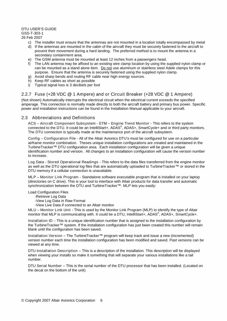
2.3 Abbreviations and DefinitionsACS – Aircraft Component Subsystem - ETM – Engine Trend Monitor - This refers to the systemconnected to the DTU. It could be an IntelliStart+, ADASd, ADAS+, SmartCycle+ and or third party monitors.The DTU connection is typically made at the maintenance port of the aircraft subsystem.
Config – Configuration File - All of the Altair Avionics DTU’s must be configured for use on a particularairframe monitor combination. Theses unique installation configurations are created and maintained in theTurbineTracker™ DTU configuration area. Each installation configuration will be given a uniqueidentification number and version. All changes to an installation configuration will cause the version numberto increase.
Log Data - Stored Operational Readings - This refers to the data files transferred from the engine monitoras well as the DTU operational log files that are automatically uploaded to TurbineTracker™ or stored in theDTU memory if a cellular connection is unavailable.
MLP – Monitor Link Program - Standalone software executable program that is installed on your laptop(directories on C drive). This is your tool to interface with Altair products for data transfer and automaticsynchronization between the DTU and TurbineTracker™. MLP lets you easily:
Load Configuration Files-Retrieve Log Data-View Log Data in Raw Format-View Live Data if connected to an Altair monitor
MLU – Monitor Link Unit - This is used by the Monitor Link Program (MLP) to identify the type of Altairmonitor that MLP is communicating with. It could be a DTU, IntelliStart+, ADASd, ADAS+, SmartCycle+.
Installation ID – This is a unique identification number that is assigned to the installation configuration bythe TurbineTracker™ system. If the installation configuration has just been created this number will remainblank until the configuration has been saved.
Installation Version – The TurbineTracker™ program will keep track and issue a new (incremented)version number each time the installation configuration has been modified and saved. Past versions can beviewed at any time.
DTU Installation Description – This is a description of the installation. This description will be displayedwhen viewing your installs so make it something that will separate your various installations like a tailnumber.
DTU Serial Number – This is the serial number of the DTU processor that has been installed. (Located onthe decal on the bottom of the unit)

DTU USER’S GUIDEGSS-T-303-126 Feb 2007
© Copyright 2007 Altair Avionics Corporation 7
Templates - The TurbineTracker™ website has system templates for various DTU systems based onengine and airframe combinations. The user has the capability of modifying these and saving them as aconfiguration or creating their own unique DTU installation configurations.
Log files – Refers to the trend or event data files downloaded from the engine monitoring system as well asDTU operational logs that are transmitted by the DTU to the TurbineTracker™ system using the cellular RFconnection. In the event the DTU can not make a cellular RF connection the log file can be transferred toTurbineTracker™ using the Monitor Link Program (MLP).
GSM - Global System for Mobile CommunicationGPRS - GSM Packet Radio ServiceISP - Internet Service ProviderIP - Internet ProtocolRF - Radio FrequencyWAP - Wireless Application ProtocolWLAN - Wireless Local Area Network
APN – Access Point Network - Is the server that the DTU logs into to transfer data to TurbineTracker™.This information can be provided by the carrier and is necessary for the DTU to establish a connection.
3 Manage DTU configuration files on the TurbineTracker™ Website.Note: For a complete and detailed listing of the TurbineTracker™ contents andfunctions refer to the TurbineTracker™ User’s Guide. It is available for downloadunder the “Support” tab by selecting the “Documents” button.
It is important to first understand how to configure the DTU so as to insure its proper operation. All of the AltairAvionics DTU’s must be configured for use on a particular airframe monitor combination. Theses uniqueinstallation configurations are created and maintained in the TurbineTracker™ DTU configuration area. Thefollowing will explain how to create new or edit existing configuration files for the DTU through the use ofTurbineTracker™.
TurbineTracker™ is a web based data management tool for Altair Avionics Corp customers. This is asubscription service, and has many useful tools for analysis, interpretation, and storage of trend andexceedance data collected from aircraft.
This section is designed to help the user understand the operation of the DTU functions in TurbineTracker™.These tools will allow the user to create and manage configurations for their DTUs.
NOTE: DTU users must contact an Altair Avionics Corp sales representative in order to gain access to thefunctions described herein. The permissions for the use of the following tools in TurbineTracker™ must begranted before they are made available to the operator.
3.1 How to log on and navigate the TurbineTracker™ website
How to Log on - User ID & Password TurbineTracker™ Account Assigned From Altair Avionics Customer Service To Customer Account Administrator You will receive an email sent to the address you provided from TurbineTracker™ with your unique log
in information: Your User Name Your Password (Case Sensitive)
Go to the TurbineTracker Website to log-in WWW.TURBINETRACKER.COM

DTU USER’S GUIDEGSS-T-303-126 Feb 2007
© Copyright 2007 Altair Avionics Corporation 8
Figure 9 – Log-in screen
After you have successfully logged in TurbineTracker™ will open to “Your Hanger” page
Figure 10 – Your Hanger page
You now have access to navigate through the TurbineTracker™ server and access the areas that you havebeen assigned permissions for.
In this screen you will enter theUser Name and Password providedto you by Altair in the boxes to theleft of the main part of the screen.
Note: Your activeaccount name is
shown here

DTU USER’S GUIDEGSS-T-303-126 Feb 2007
© Copyright 2007 Altair Avionics Corporation 9
Navigating in TurbineTracker™TABS
Click a on thedesired tab tochange pages
Note: You may not havepermission to view all of
the these tabs
Option ButtonsClick the buttonsto select differentoptions related tothe current page
Note: If a button is grayyou don’t have
permission to select it
Radio ButtonsClick radio
buttonsto mark them as
checked
HyperlinksClick to open another
window, option box or tomake a selection
If you forget to log OffTurbineTracker™ willautomatically time outand log you off after a
few minutes ofinactivity
Figure 11 – Navigating in TurbineTracker™
TurbineTracker™ Tab contents at a glance: Your Hangar - Fleet Status Configuration - Create & Edit monitor configurations File Transfer - Upload & Download Configuration and Log Files Data Analysis - Analyze ETM Log Data DTU – Create, Edit & download Configurations, Analyze DTU Log Data Support - Download Manuals & Contact Help Desk User Administration - Create & Edit Users
For a complete and detailed listing of the TurbineTracker™ contents and functions refer tothe TurbineTracker™ User’s Guide. It is available for download under the “Support” tab byselecting the “Documents” button.
3.2 Create or change DTU configurations files.
To create a configuration for the DTU, log on to TurbineTracker™ do the following:Click on the DTU tab (see Figure 12)NOTE: If you don’t have the DTU tab shown, the first step is to contact Altair Avionics Corp to have theDTU tab added to your TurbineTracker™ account. From here you can configure each of your DTUs.

DTU USER’S GUIDEGSS-T-303-126 Feb 2007
© Copyright 2007 Altair Avionics Corporation 10
Figure 12- Your Hanger Page with DTU TabNext select the “Configuration” button on the left side of the screen (see figure 13)
Figure 13 - DTU information page
3.2.1 Add new DTUUpon selecting the “Configuration” button a page displaying any active or inactive DTU configurations in youraccount will open. From here the operator is able to select an existing configuration to edit or may create newfiles by selecting the Add New DTU hyperlink. (See figure 14).

DTU USER’S GUIDEGSS-T-303-126 Feb 2007
© Copyright 2007 Altair Avionics Corporation 11
Figure 14 - DTU configuration page
Clicking on the Add New DTU will bring you to a page that contains system templates for creatingconfigurations. Currently the list contains a limited amount of templates. As the DTU is certified on moreaircraft this list will increase in options.
The template named PW306B DTU Template is used for transferring data that is collected by the Pratt &Whitney engine computer installed on some 306 series engines. Likewise the template labeled Twin IS+DTU Template is designed for a special application for one of Altair Avionics Corp customers.
Currently any new DTU will use the template labeled Altair DTU Template. This is the generic template thatis designed for use with any Altair Avionics Corp Engine monitor.
NOTE: Altair Avionics Corp Generation III Monitors must have version 3.2.0 or higher in order to becompatible with a DTU. If the monitor does not have v3.2.0 or higher code the processor will not be ableto connect to the DTU, and therefore, no data will be transferred. You will need to contact AltairCustomer Support for an upgrade.

DTU USER’S GUIDEGSS-T-303-126 Feb 2007
© Copyright 2007 Altair Avionics Corporation 12
Figure 15 - Configuration Templates
3.2.2 DTU DescriptionUpon selecting the Altair DTU Template hyperlink, a page where the DTU description and serial number can beentered will open. The DTU description and serial number fields are text fields where the information you enterwill be displayed throughout the DTU tab to help you navigate and select configurations to work with. It issuggested that you name the DTU configuration using the aircraft registration, monitor the DTU is being use inconjunction with or the cellular carrier that is providing service. By doing this it makes it easier to distinguish oneunit from another with in your account. See the example in Figure 16 for reference.
Figure 16 - DTU description and Serial NumberOnce a description has been given and the serial number has been recorded click the keep these values buttonat the bottom of the page.

DTU USER’S GUIDEGSS-T-303-126 Feb 2007
© Copyright 2007 Altair Avionics Corporation 13
3.2.3 GPRS ConfigurationNext the operator will need to configure the connection information for the DTU. This will tell the DTU whichservice provider is being used as well as type of connection and login information (some carriers require userID’s and passwords to access the GSM network). To accomplish this select the GPRS Config Button on the lefthand side of the web page. This will open the window in figure 17.
Figure 17 - GPRS InformationThe calling plan dropdown menu contains some cellular service providers for use with the DTU, but it is in noway a complete listing. The operator may contact Altair Avionics Corp to add carriers to this list if necessary,but the Custom selection will allow the operator to enter the information that is necessary to establish aconnection through the DTU.
The only mode the DTU is able to support currently in GPRS. As the technology is developed other connectionmodes will become available.
An APN, or Access Point Network, is the server that the DTU logs into to transfer data to TurbineTracker™.This information can be provided by the carrier and is necessary for the DTU to establish a connection.User ID and Password are required by some service providers. Again, if the carrier requires this information itneeds to be entered here in order for the DTU to establish a connection and transfer data to the internet.The Phone field is currently not used and only for the rare instance the DTU would need to dial in to an ISPthrough the cellular provider to establish a connection to TurbineTracker™.
By selecting one of the options from the calling plan dropdown menu, most of the necessary information isalready in the Altair Avionics Corp data base. The only exception is those carriers who require a user ID andpassword to logon to their network, in which case those fields would have to be filled in by the operator.
NOTE: For a list of International GPRS providers visit http://www.access-sys-eu.com/gprs.html. This isnot an Altair Avionics Corp website, nor is it affiliated with Altair Avionics Corp; therefore we can notguarantee the accuracy of the information contained within this website.

DTU USER’S GUIDEGSS-T-303-126 Feb 2007
© Copyright 2007 Altair Avionics Corporation 14
Upon completing the GPRS information select the keep these value button at the bottom ofthe page.
3.2.4 ACS selectionTo complete the configuration file for the new DTU the ASC information will need to be completed. Select theACS button your ACS based on the aircraft configuration. If you attempt to configure ASC incorrectly the DTUwill not establish a connection to the engine monitor on the aircraft.
Table 1 - ACS Selection
Single Altair monitor ACS0
Dual Altair monitors ACS0 & ACS1
306B ACS1 & ACS2
Other engine monitors Normally ACS0*
*If unsure of the ACS selection for your configuration contact Altair Customer Support for guidance
Figure 18 - ACS SelectionOnce the ACS to be configured has been chosen the following window will appear.

DTU USER’S GUIDEGSS-T-303-126 Feb 2007
© Copyright 2007 Altair Avionics Corporation 15
Figure 19 - ACS InformationThe monitor configuration dropdown menu will list the monitors in the operators account. From these choicesthe appropriate engine monitor needs to be selected. This is a list of all monitors in the operators’ account,regardless of whether or not the monitor is compatible with the DTU. Be careful to choose the correct monitor, ifthe wrong monitor is selected the DTU will not be able to establish a connection to the aircraft monitor.Next the monitor type will need to be selected. From the dropdown menu select the monitor best suited for youDTU. This will tell the DTU which type of engine monitor it is connecting to. Because the DTU is capable ofconnection engine monitors other than just Altair’s monitors selecting one of the types from the dropdown menualso tells the DTU what language to transmit the information in as well.
Figure 20 - Monitor Type selectionNote: Most operators using the DTU with an Altair monitor running V4.0 or higher firmware use theALTAIR_V_RUN monitor type. If you are unsure of the monitor type contact Altair Customer Support forassistance.

DTU USER’S GUIDEGSS-T-303-126 Feb 2007
© Copyright 2007 Altair Avionics Corporation 16
ALTAIR should be selected when the DTU is being used with one of our Generation IIImonitors with V3.2 firmware.
ALTAIR_DUAL_ADAS should be used when an ADAS+ or an ADAS+ Upgrade monitorwith V3.2 firmware are connected to the DTU. The ADAS+ Upgrade used on a largeportion of the FMP fixed wing operators contains two processor boards in a singleextrusion. This was done to allow two engines to be monitored. This is a special case forthe DTU.
ALTAIR_DUAL_SMART should be used when SmartCycle+ Twin monitor with V3.2firmware is connected to the DTU. The SmartCycle+ Twin monitor is a special case thatwas developed for twin engine helicopters. This monitor contains two processor boards ina single extrusion. This was done to allow two engines to be monitored. This is a specialcase for the DTU.
ALTAIR_V4_CFG should be selected when the DTU is being used with one of ourGeneration III monitors with V4.0 or higher firmware. Places monitor in configurationmode (Trend Lamp illuminated and hot start detection disabled) during the monitor to DTUlog transfer process. I. E. at completion of engine run.
ALTAIR_V4_RUN (preferred for Altair monitors) should be selected when the DTU isbeing used with one of our Generation III monitors with V4.0 or higher firmware. Leavesthe monitor in run mode (hot start detection active if applicable) during the monitor to DTUlog transfer process. I. E. at completion of engine run.
PW306BL & PW306BR should be used when the DTU will transmit information collectedby the Pratt & Whitney PW306 Engine monitor. This is an OEM data collection devicethat is compatible with the DTU, but uses a different code than the Altair monitors. Makesure to choose the correct type of monitor for you engine to ensure that data issuccessfully transmitted.
Figure 21 ACS configurationThe connect field should have ON selected. This allows the DTU to connect to the monitor to receive data andlater transfer this information to TurbineTracker™.
Once all the ACS information has been filled in hit the keep these values button at the bottom of the page.

DTU USER’S GUIDEGSS-T-303-126 Feb 2007
© Copyright 2007 Altair Avionics Corporation 17
Once all information has been entered and verified select the “Save this Configuration” hyperlink. By selectingthis, the DTU configuration will be saved on TurbineTracker™.
The user should now see the configuration that was just created listed in the configuration area of the DTU tab.
DTU TAB
View all versionsSelect this link to list all
previous versionsi. e. 1 thru 8
Selecting a Version Number Hyperlink or Add New DTU willopen the View/Edit Configuration Menu for the selected config
Delete, Deactivate & Activateshould only be used by Account
Administrators and Advanced Users
Figure 22 Configuration tableThis configuration will now need to be loaded into the DTU.
3.3 Downloading a DTU Configuration File to a Laptop Computer
The configuration file contains the special information needed by the DTU to work with that particular aircraft.To download the configuration file for the DTU, follow the steps outlined in this section.While in the DTU tab in TurbineTracker™ choose the Download Config button at the left hand side of thescreen. This will open a webpage that list all of the DTU configurations in the account. From the list choosewhich configuration to download to the laptop.
Figure 23 - DTU Configuration Download Button

DTU USER’S GUIDEGSS-T-303-126 Feb 2007
© Copyright 2007 Altair Avionics Corporation 18
DTU TAB
View all versionsSelect this link to list all
previous versionsi. e. 1 thru 8
Users can manually Download Configuration Filesby selecting the desired configurations Hyperlink
and following the standard Windows prompt
Figure 24 - Downloadable DTU ConfigurationsSelect the blue hyperlink under version to download that configuration file. A screen asking whether to open thefile or save the file will pop up. Choose to save the file to the laptop. Remember the location the file will besaved to so that it can be easily found when it is time to load the file into the DTU. Click, save on the pop upwindow.The Configuration has now been saved to the laptop computer. Take the same laptop used to download theconfiguration file out to the aircraft and connect to the DTU. Once connected to the DTU load the configurationfile into the unit.
4 DTU / Laptop Interface using the Monitor Link Program (MLP)
4.1 Installing your SIM card into the DTUCellular communication is provided by means of a Tri-Band GSM (EGSM900, GSM1800 and GSM1900)modem. The customer supplied SIM card must have data (GPRS) enabled. It is recommended the SIM card betested with a cell phone prior to installation.
The SIM card must be activated by the provider. It must have PIN access disabled or the card will be locked requiring the PUK code from the carrier. If PIN must be used the default must be set to 1234 (Your card will be locked requiring PUK activation if
you use a different PIN)
NOTE: setting the PIN to 1234 is not recommended since the DTU will assign a random password at thefirst power-up. If the DTU assigns a password it can never be changed and the SIM card will only beuseable in the DTU that assigned it.

DTU USER’S GUIDEGSS-T-303-126 Feb 2007
© Copyright 2007 Altair Avionics Corporation 19
SIM card installationSIM card installationUsing the Hexscrewdriver, remove2 screws indicated
With Hexscrewdriver, pressthe yellow ejectbutton
Figure 25 - Access to the SIM card
This will cause the SIM CardHolder to pop out of the DTU.Put new SIM card in SIM cardholder
Note the SIM card can only go into theholder one way. Line up the notchedcorner on the SIM with the matchingnotch on the SIM card holder.
Slide SIM card holder back intothe DTU. Be careful to line upthe card in the slot.Put SIM card cover back on.Unit is ready to use.
Figure 26 - Installing the SIM card

DTU USER’S GUIDEGSS-T-303-126 Feb 2007
© Copyright 2007 Altair Avionics Corporation 20
4.2 Setup the Laptop for the DTU using MLPFor the initial installation and operation of a DTU the operator will need a laptop with the Monitor Link Program(MLP). MLP is the software that is used to communicate with the Altair products via laptop computer. WithoutMLP it will not be possible to load files or retrieve files. It is also necessary to use the most recent version ofMLP for all file transfers.
Note: For a complete and detailed listing of the MLP and its functions refer to the MLP User’s Guide. Itis available for download under the “Support” tab by selecting the “Documents” button.
If you do not have MLP version 6.7.2 or higher on your laptop you will need to download it fromTurbineTracker™, Support tab by selecting the System Updates button and following the on screen instructions.
NOTE: The following Transparent Mode feature is only required if using the DTU with an Altair monitorotherwise skip to: Section 3.3 Establish an MLP connection and Load configuration files into the DTU.
4.2.1 Enable the Transparent Mode featureOnce MLP has been installed on the laptop it will need to be setup to allow certain functions with a DTUinstalled in the aircraft that has an Altair engine monitor. For example it is necessary to enable this function inMLP in order to put the DTU into Transparent Mode so that the laptop can communicate directly with the Altairengine monitor.
Note: The Transparent Mode feature is only available when the DTU is connected to Altair enginemonitors.
To enable this feature open MLP and select Edit from the menu at the top of the page.Next select Options from the menu. (See Figure 27)

DTU USER’S GUIDEGSS-T-303-126 Feb 2007
© Copyright 2007 Altair Avionics Corporation 21
Figure 27 - MLP setup
This will open the window in Figure 28 - Enabling DTU Connect. Check the DTU connect box and select OK,this will bring up a message that MLP will have to be restarted, hit OK. Restart MLP.
Figure 28 - Enabling DTU Connect

DTU USER’S GUIDEGSS-T-303-126 Feb 2007
© Copyright 2007 Altair Avionics Corporation 22
Upon restarting MLP there should be a button at the top labeled DTU with a red background (See Figure 29).When this button is pressed it will put the DTU into a transparent mode that allows the engine monitor tocommunicate with the laptop.
Figure 29 - DTU Button in MLPNow that MLP has been setup to allow use of special DTU functions the operator can load the configuration filecreated in TurbineTracker™ into the DTU. The DTU will need to be configured before the engine monitor.
4.3 Establish an MLP connection to Load configuration files into the DTU.
To load the configuration file into the DTU follow the steps outlined below.(Figure 30).1) Select Edit2) Select Communication port3) Select Auto Detect

DTU USER’S GUIDEGSS-T-303-126 Feb 2007
© Copyright 2007 Altair Avionics Corporation 23
Figure 30 - Establishing Communication with the DTUOnce MLP indicates that the communications port has been successfully detected it is possible to load theconfiguration file. The following steps will allow the operator to load the configuration file into the DTU (SeeFigure 31).
Select MLU Select Configure Unit
The standard windows file open box will prompt you for the location of the DTU config fileNote: If prompted to reset the log select yes to reset it since the DTU log must be empty to load a config file.
MLP will indicate the progress of the upload in the status bar.

DTU USER’S GUIDEGSS-T-303-126 Feb 2007
© Copyright 2007 Altair Avionics Corporation 24
Figure 31 - Loading the Configuration File into the DTUAfter the DTU has been configured it is ready for normal operation.
4.3.1 Putting the DTU into Transparent ModeTo put the DTU into transparent mode first establish communication between the DTU and laptop. Uponestablishing a connection with the DTU, click the red DTU button.
Note: The Transparent Mode feature is only available when the DTU is connected to Altair enginemonitors.
A prompt to select an ACS will popup (See Figure 32). You normally choose ACS 1 for all single Altair AvionicsCorp engine monitors (if your installation uses two engine monitors select the desired ACS). If another ACS hasbeen setup for a different monitoring system then that is the ACS that should be chosen the click OK.

DTU USER’S GUIDEGSS-T-303-126 Feb 2007
© Copyright 2007 Altair Avionics Corporation 25
Figure 32 - Selecting an ACSOnce the DTU established the connection to the ACS (it might take a few seconds, so be patient) the red DTUbutton at the top of the MLP Page will turn green.(Figure 33) The green button signifies that the DTU is intransparent mode. This means that MLP is communicating directly with the engine monitor and not the DTU.

DTU USER’S GUIDEGSS-T-303-126 Feb 2007
© Copyright 2007 Altair Avionics Corporation 26
Figure 33 - DTU in Transparent ModeWhen finished working with the engine monitor click the green DTU button to take the DTU out of transparentmode.
NOTE: Closing MLP without exiting transparent mode will cause the DTU to remain in transparent mode untilthe power to the aircraft is cycled. i.e. by closing MLP without exiting transparent mode and then attempting todo another Autodetect without cycling the aircraft power, MLP will establish a connection directly to the enginemonitor.
3.4 Retrieve log data from DTU memory.Synchronize MLP to the DTU and TurbineTracker™
The proper method of using the SYNCHRONIZE function is this:Sync to TurbineTracker™
Sync to Aircraft.Sync to TurbineTracker™
NOTE: Ensure you have the current version of the Monitor Link Program (MLP).The current version is available from Turbine Tracker under the “Support Tab” and “Systems Update”button (See Checklist CUST-T- 417-1).
1) Establish connection to the internet with the laptop computer to be used for loading and retrieving files toand from the processor in the aircraft.
2) Open the MLP.exe program.
DTU USER’S GUIDEGSS-T-303-126 Feb 2007
© Copyright 2007 Altair Avionics Corporation 27
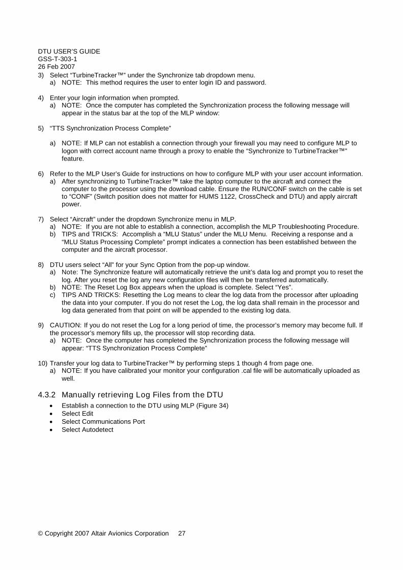
3) Select “TurbineTracker™” under the Synchronize tab dropdown menu.a) NOTE: This method requires the user to enter login ID and password.
4) Enter your login information when prompted.a) NOTE: Once the computer has completed the Synchronization process the following message will
appear in the status bar at the top of the MLP window:
5) “TTS Synchronization Process Complete”
a) NOTE: If MLP can not establish a connection through your firewall you may need to configure MLP tologon with correct account name through a proxy to enable the “Synchronize to TurbineTracker™”feature.
6) Refer to the MLP User’s Guide for instructions on how to configure MLP with your user account information.a) After synchronizing to TurbineTracker™ take the laptop computer to the aircraft and connect the
computer to the processor using the download cable. Ensure the RUN/CONF switch on the cable is setto “CONF” (Switch position does not matter for HUMS 1122, CrossCheck and DTU) and apply aircraftpower.
7) Select “Aircraft” under the dropdown Synchronize menu in MLP.a) NOTE: If you are not able to establish a connection, accomplish the MLP Troubleshooting Procedure.b) TIPS and TRICKS: Accomplish a “MLU Status” under the MLU Menu. Receiving a response and a
“MLU Status Processing Complete” prompt indicates a connection has been established between thecomputer and the aircraft processor.
8) DTU users select “All” for your Sync Option from the pop-up window.a) Note: The Synchronize feature will automatically retrieve the unit’s data log and prompt you to reset the
log. After you reset the log any new configuration files will then be transferred automatically.b) NOTE: The Reset Log Box appears when the upload is complete. Select “Yes”.c) TIPS AND TRICKS: Resetting the Log means to clear the log data from the processor after uploading
the data into your computer. If you do not reset the Log, the log data shall remain in the processor andlog data generated from that point on will be appended to the existing log data.
9) CAUTION: If you do not reset the Log for a long period of time, the processor’s memory may become full. Ifthe processor’s memory fills up, the processor will stop recording data.a) NOTE: Once the computer has completed the Synchronization process the following message will
appear: “TTS Synchronization Process Complete”
10) Transfer your log data to TurbineTracker™ by performing steps 1 though 4 from page one.a) NOTE: If you have calibrated your monitor your configuration .cal file will be automatically uploaded as
well.
4.3.2 Manually retrieving Log Files from the DTU Establish a connection to the DTU using MLP (Figure 34) Select Edit Select Communications Port Select Autodetect

DTU USER’S GUIDEGSS-T-303-126 Feb 2007
© Copyright 2007 Altair Avionics Corporation 28
Figure 34 - Establishing a Connection to the DTUOnce the communication port is successfully detected:
Select MLU (Figure 35) Select Retrieve Unit’s Data Log Save the Log file Select Yes to reset the Unit’s Data Log when prompted
DTU USER’S GUIDEGSS-T-303-126 Feb 2007
© Copyright 2007 Altair Avionics Corporation 29
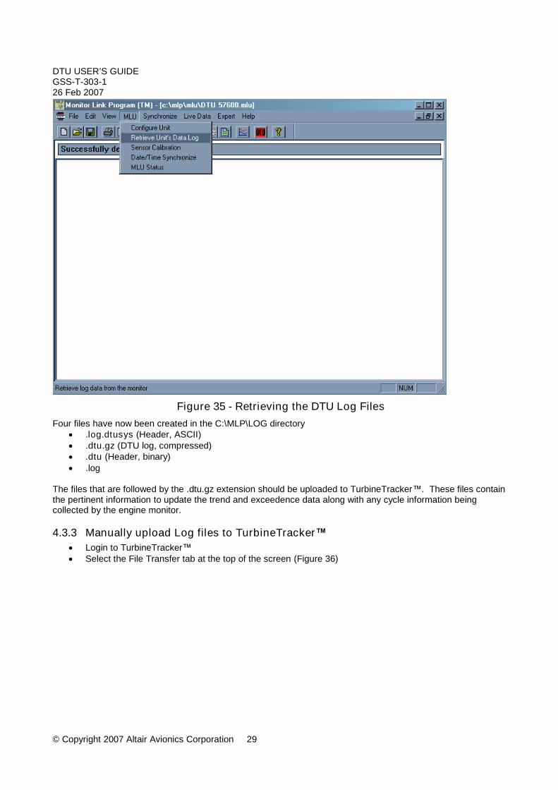
Figure 35 - Retrieving the DTU Log FilesFour files have now been created in the C:\MLP\LOG directory
.log.dtusys (Header, ASCII) .dtu.gz (DTU log, compressed) .dtu (Header, binary) .log
The files that are followed by the .dtu.gz extension should be uploaded to TurbineTracker™. These files containthe pertinent information to update the trend and exceedence data along with any cycle information beingcollected by the engine monitor.
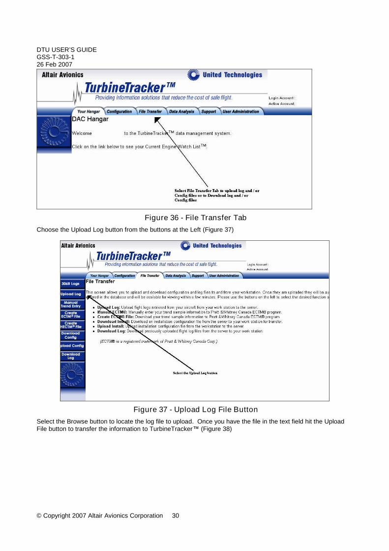
4.3.3 Manually upload Log files to TurbineTracker™ Login to TurbineTracker™ Select the File Transfer tab at the top of the screen (Figure 36)
DTU USER’S GUIDEGSS-T-303-126 Feb 2007
© Copyright 2007 Altair Avionics Corporation 30
Figure 36 - File Transfer TabChoose the Upload Log button from the buttons at the Left (Figure 37)
Figure 37 - Upload Log File ButtonSelect the Browse button to locate the log file to upload. Once you have the file in the text field hit the UploadFile button to transfer the information to TurbineTracker™ (Figure 38)

DTU USER’S GUIDEGSS-T-303-126 Feb 2007
© Copyright 2007 Altair Avionics Corporation 31
Figure 38 - Selecting and Loading a File to TurbineTracker™
4.4 Verify correct operation of the DTU
4.4.1 System Boot-up TestThe Data Transmission Unit (DTU) incorporates a “push-to-test” dual lamp indicator to provide the operator withinformation about the system.DTU status processing involves the display of the DTU status to the user. Two lamps and a button areemployed to present and control the DTU status:
1. DTU Status Lamp: displays overall system status2. RF Status Lamp: displays the current state of the Micro Server (MS) power3. DTU Button: accepts user Acknowledge input to clear the Status Lamp and to enter Maintenance mode.
When power is first applied the Data Transmission Unit initializes, the fault lamp will indicate the various stagesof the process. The initialization sequence will proceed as follows:
When the processor’s power is first applied, the fault lamp will illuminate both the DTU Status and RF Statuslamps for 3 to 5 seconds while the system performs a series of self-tests. The following self-tests are performedduring initialization:
1. Micro Controller Test2. Lamp Test (momentary flicker)3. Temporary Memory Test4. Data Log Memory Test5. Program Integrity Test
At the completion of the DTU processor initialization, the DTU Status lamp and RF Status lamp will indicatesystem status as described below.
The DTU Status Lamp is used to inform a maintenance person of the DTU status.
DTU USER’S GUIDEGSS-T-303-126 Feb 2007
© Copyright 2007 Altair Avionics Corporation 32
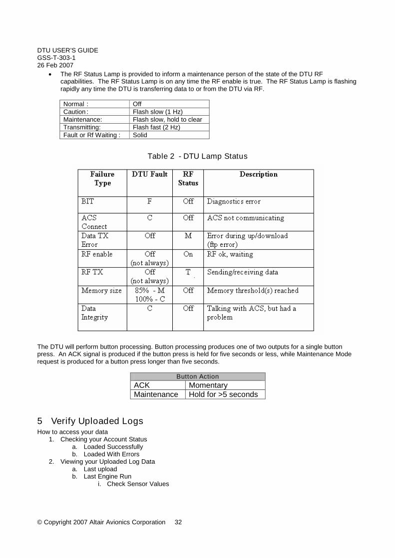
The RF Status Lamp is provided to inform a maintenance person of the state of the DTU RFcapabilities. The RF Status Lamp is on any time the RF enable is true. The RF Status Lamp is flashingrapidly any time the DTU is transferring data to or from the DTU via RF.
Normal : OffCaution : Flash slow (1 Hz)Maintenance: Flash slow, hold to clearTransmitting: Flash fast (2 Hz)Fault or Rf Waiting : Solid
Table 2 - DTU Lamp Status
The DTU will perform button processing. Button processing produces one of two outputs for a single buttonpress. An ACK signal is produced if the button press is held for five seconds or less, while Maintenance Moderequest is produced for a button press longer than five seconds.
Button ActionACK MomentaryMaintenance Hold for >5 seconds
5 Verify Uploaded LogsHow to access your data
1. Checking your Account Statusa. Loaded Successfullyb. Loaded With Errors
2. Viewing your Uploaded Log Dataa. Last uploadb. Last Engine Run
i. Check Sensor Values

DTU USER’S GUIDEGSS-T-303-126 Feb 2007
© Copyright 2007 Altair Avionics Corporation 33
c. Last Trendi. Check Sensor Values
d. Last Evente. Last Flagf. Last Fault
3. Viewing Uploaded DTU Logsa. Last Transmission Success
5.1 Checking your Account StatusShows you what has happened recently with your account in terms of data log and configuration uploads.
Accessed via the Hangar page Provides detailed information about an upload
o Number of engine runs, exceedences, auto-trends etc.
After you log in to TurbineTracker you will be presented with: Hyperlink to your present Account Status (See Figure 40)
Figure 39 - Log in page

DTU USER’S GUIDEGSS-T-303-126 Feb 2007
© Copyright 2007 Altair Avionics Corporation 34
Account Status
Displays a report ofConfiguration and Log
File uploads to youraccount.
The Account StatusScreen will displayinitially data for one
week from the date ofaccess as a default.
You can change thedate range of the
report by selecting thedrop down date boxes.
Figure 40 - Account status
Copyright © 2006 ALTAIR AVIONICS COPORATION - All rights reserved
Your Hanger TabAccount Status
All of your Log andConfiguration upload
activity during the selecteddates will be listed inchronological order.
Reading DescriptionMessages
The Hyperlink under theDescription columnopens the UploadSummary pop-up
window. The reason forthe upload error or the
upload successsummary will be
displayed.
Figure 41 - Upload summery
Select the description Hyperlink to: View a summery of what was contained in the uploaded
logs View information about any errors

DTU USER’S GUIDEGSS-T-303-126 Feb 2007
© Copyright 2007 Altair Avionics Corporation 35
5.2 Viewing your Uploaded Log DataAfter selecting the Data Analysis tab on top, select the View Log Data button on the left. You will be presentedwith the Summary Data View table. (Figure 42)
You can also filter the table viewby Airframe, Engine Type, Unit
Type and Date You can easilyView Log Datafrom the entire
fleet by selectingthe desired
Hyperlink in thetable
Figure 42 - Viewing Logs
The date of Last Upload that was successful will be listed.Select the number of Engine Runs hyperlink to display a chronological list of engine runs (Figure 43)
Figure 43 – Viewing Engine Runs

DTU USER’S GUIDEGSS-T-303-126 Feb 2007
© Copyright 2007 Altair Avionics Corporation 36
5.3 Viewing your uploaded DTU LogsAfter selecting the DTU tab on top, select the DTU Logs button on the left. You will be presented with the DTUselection page. (Figure 44)
After selecting the Blue DTU Logs button you will be presented withthe overview table of your fleets DTU activity for the last 30 day’s
You can also enter the date range todo a custom search. (Defaults is 30
day’s from the current date).
DTU activity overview
ExampleYourTail
Numbernormally
Here
Figure 44 -Viewing DTU logsClicking on your tail number hyperlink open a table containing the associated DTU’s entire log in chronologicalorder. (Figure 45)

DTU USER’S GUIDEGSS-T-303-126 Feb 2007
© Copyright 2007 Altair Avionics Corporation 37
Figure 45 - Viewing all logs
ExampleYourTail
NumberHere
All of theselected
DTU’s logsare displayed
in achronological
order
You also havethe option toselect which
logs todisplay

DTU USER’S GUIDEGSS-T-303-126 Feb 2007
© Copyright 2007 Altair Avionics Corporation 38
Selecting the desired Hyperlink opens a chronological list of the associated logs
The selectedDTU’s MS
(Microserver)TransmissionSuccess logs
are displayed ina chronological
order
Shows the date and time of the last upload toTurbineTracker
ExampleYourTail
NumberHere
Figure 46 – Viewing Transmission logs
Selecting the desired Hyperlink opens a chronological list of the associated logs
Both of the selectedDTU’s
MS TX SuccessACS Data Retrieval
logs are displayed ina chronological
order
Shows how long it took to upload after engine shutdownMS TX Success - ACS Data Retrieval = Last Tx Duration
ExampleYourTail
NumberHere
Figure 47 – Viewing duration info
DTU USER’S GUIDEGSS-T-303-126 Feb 2007
© Copyright 2007 Altair Avionics Corporation 39
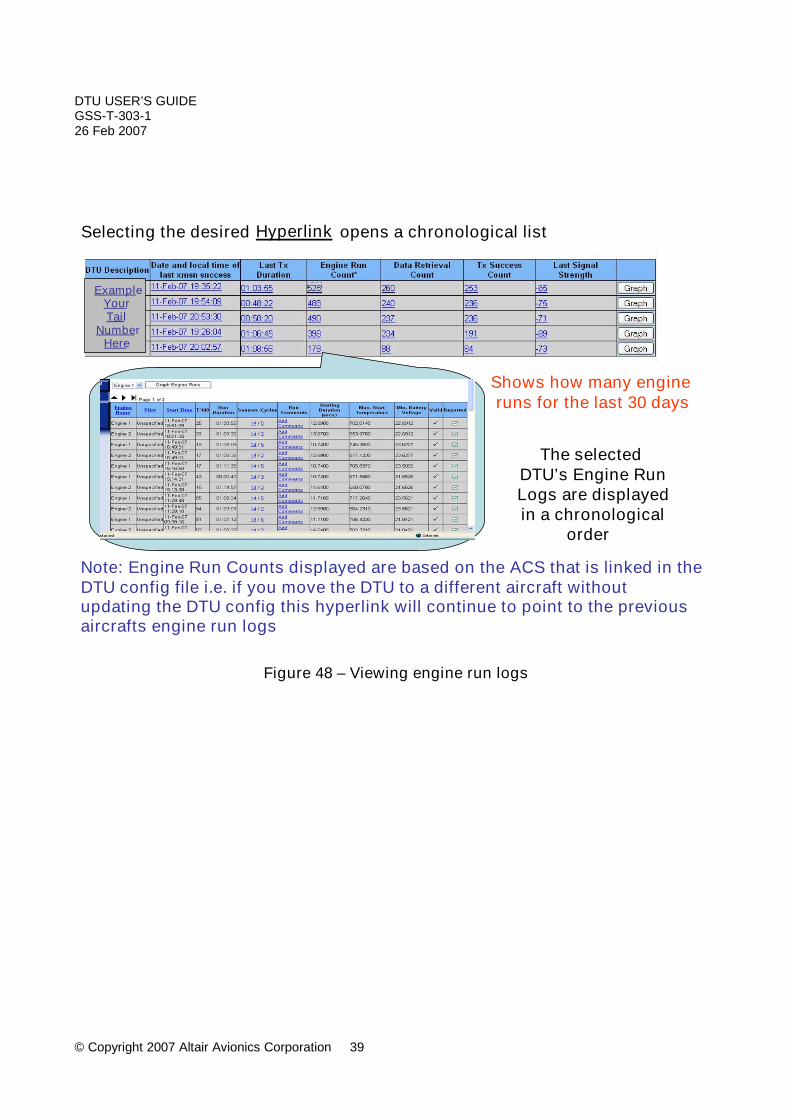
Figure 48 – Viewing engine run logs
Selecting the desired Hyperlink opens a chronological list
The selectedDTU’s Engine RunLogs are displayedin a chronological
order
Note: Engine Run Counts displayed are based on the ACS that is linked in theDTU config file i.e. if you move the DTU to a different aircraft withoutupdating the DTU config this hyperlink will continue to point to the previousaircrafts engine run logs
Shows how many engineruns for the last 30 days
ExampleYourTail
NumberHere

DTU USER’S GUIDEGSS-T-303-126 Feb 2007
© Copyright 2007 Altair Avionics Corporation 40
Figure 49 - Data retrieval info
Selecting the desired Hyperlink opens a chronological list of the associated logs
The selected DTU’sACS Data Retrievelogs are displayedin a chronological
order
Shows how manytimes the DTU hasretrieved log data
for the last 30 days
Note: Number will be close to the number of engine runs but may not matchi.e. When you start the engine quickly after shut down or start only one engine
Dual engine run count should be close to double
ExampleYourTail
Number

DTU USER’S GUIDEGSS-T-303-126 Feb 2007
© Copyright 2007 Altair Avionics Corporation 41
Figure 50 – Viewing Microserver Transmission Success logs
Selecting the desired Hyperlink opens a chronological list of the associated logs
Shows howmany times the
DTU hassuccessfully
uploaded logdata to
TurbineTrackerin the last 30
daysNote: Number will be close to the number of Data Retrieval coun ts but may notmatch i.e.: When you start the engine quickly after shut down or when the DTU has nocellular connection.
ExampleYourTail
NumberHere

DTU USER’S GUIDEGSS-T-303-126 Feb 2007
© Copyright 2007 Altair Avionics Corporation 42
Figure 51 – Viewing transmission count info
Selecting the desired Hyperlink opens a chronological list of the associated logs
Shows howmany times the
DTU hassuccessfully
uploaded logdata to
TurbineTrackerin the last 30
daysNote: Number will be close to the number of Data Retrieval coun ts but may notmatch i.e.: When you start the engine quickly after shut down or when the DTU has nocellular connection.
ExampleYourTail
NumberHere

DTU USER’S GUIDEGSS-T-303-126 Feb 2007
© Copyright 2007 Altair Avionics Corporation 43
Caution: You must use your current ICA for all troubleshooting
Selecting the desired Hyperlink opens a chronological list of the associated logs
Shows howstrong the
cellular signalwas during the
DTU’s lastsuccessfulUpload to
TurbineTrackerGSM
-255 = no signal-0 = perfect signalGSM signal of at least -91 recommended for reliable data transfer
ExampleYourTail
NumberHere
Figure 52 – Viewing signal strength info
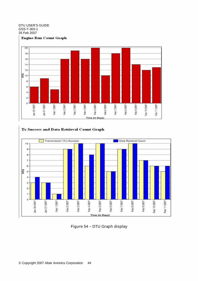
Selecting the desired Graph button opens a graphical display for the selectedTime period (default is the last 30 days)
Engine Run Count GraphTx Success and Data Retrieval Count Graph
Example
Example
Example
Example
Example
Figure 53 – Viewing DTU Graph
DTU USER’S GUIDEGSS-T-303-126 Feb 2007
© Copyright 2007 Altair Avionics Corporation 44
Figure 54 – DTU Graph display
DTU USER’S GUIDEGSS-T-303-126 Feb 2007
© Copyright 2007 Altair Avionics Corporation 45
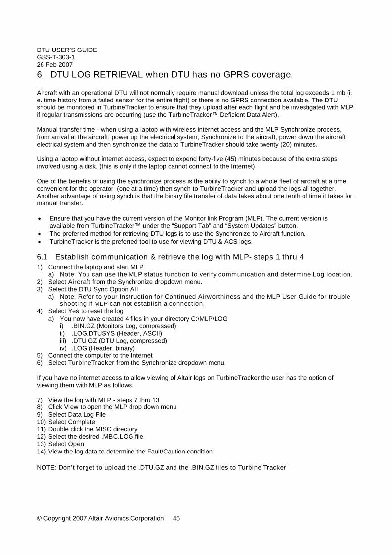
6 DTU LOG RETRIEVAL when DTU has no GPRS coverage
Aircraft with an operational DTU will not normally require manual download unless the total log exceeds 1 mb (i.e. time history from a failed sensor for the entire flight) or there is no GPRS connection available. The DTUshould be monitored in TurbineTracker to ensure that they upload after each flight and be investigated with MLPif regular transmissions are occurring (use the TurbineTracker™ Deficient Data Alert).
Manual transfer time - when using a laptop with wireless internet access and the MLP Synchronize process,from arrival at the aircraft, power up the electrical system, Synchronize to the aircraft, power down the aircraftelectrical system and then synchronize the data to TurbineTracker should take twenty (20) minutes.
Using a laptop without internet access, expect to expend forty-five (45) minutes because of the extra stepsinvolved using a disk. (this is only if the laptop cannot connect to the Internet)
One of the benefits of using the synchronize process is the ability to synch to a whole fleet of aircraft at a timeconvenient for the operator (one at a time) then synch to TurbineTracker and upload the logs all together.Another advantage of using synch is that the binary file transfer of data takes about one tenth of time it takes formanual transfer.
Ensure that you have the current version of the Monitor link Program (MLP). The current version isavailable from TurbineTracker™ under the “Support Tab” and “System Updates” button.
The preferred method for retrieving DTU logs is to use the Synchronize to Aircraft function. TurbineTracker is the preferred tool to use for viewing DTU & ACS logs.
6.1 Establish communication & retrieve the log with MLP- steps 1 thru 41) Connect the laptop and start MLP
a) Note: You can use the MLP status function to verify communication and determine Log location.2) Select Aircraft from the Synchronize dropdown menu.3) Select the DTU Sync Option All
a) Note: Refer to your Instruction for Continued Airworthiness and the MLP User Guide for troubleshooting if MLP can not establish a connection.
4) Select Yes to reset the loga) You now have created 4 files in your directory C:\MLP\LOG
i) .BIN.GZ (Monitors Log, compressed)ii) .LOG.DTUSYS (Header, ASCII)iii) .DTU.GZ (DTU Log, compressed)iv) .LOG (Header, binary)
5) Connect the computer to the Internet6) Select TurbineTracker from the Synchronize dropdown menu.
If you have no internet access to allow viewing of Altair logs on TurbineTracker the user has the option ofviewing them with MLP as follows.
7) View the log with MLP - steps 7 thru 138) Click View to open the MLP drop down menu9) Select Data Log File10) Select Complete11) Double click the MISC directory12) Select the desired .MBC.LOG file13) Select Open14) View the log data to determine the Fault/Caution condition
NOTE: Don’t forget to upload the .DTU.GZ and the .BIN.GZ files to Turbine Tracker
DTU USER’S GUIDEGSS-T-303-126 Feb 2007
© Copyright 2007 Altair Avionics Corporation 46
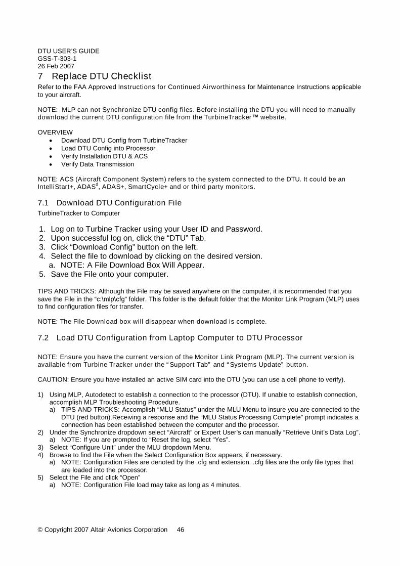
7 Replace DTU ChecklistRefer to the FAA Approved Instructions for Continued Airworthiness for Maintenance Instructions applicableto your aircraft.
NOTE: MLP can not Synchronize DTU config files. Before installing the DTU you will need to manuallydownload the current DTU configuration file from the TurbineTracker™ website.
OVERVIEW Download DTU Config from TurbineTracker Load DTU Config into Processor Verify Installation DTU & ACS Verify Data Transmission
NOTE: ACS (Aircraft Component System) refers to the system connected to the DTU. It could be anIntelliStart+, ADASd, ADAS+, SmartCycle+ and or third party monitors.
7.1 Download DTU Configuration FileTurbineTracker to Computer
1. Log on to Turbine Tracker using your User ID and Password.2. Upon successful log on, click the “DTU” Tab.3. Click “Download Config” button on the left.4. Select the file to download by clicking on the desired version.
a. NOTE: A File Download Box Will Appear.5. Save the File onto your computer.
TIPS AND TRICKS: Although the File may be saved anywhere on the computer, it is recommended that yousave the File in the “c:\mlp\cfg” folder. This folder is the default folder that the Monitor Link Program (MLP) usesto find configuration files for transfer.
NOTE: The File Download box will disappear when download is complete.
7.2 Load DTU Configuration from Laptop Computer to DTU Processor
NOTE: Ensure you have the current version of the Monitor Link Program (MLP). The current version isavailable from Turbine Tracker under the “Support Tab” and “Systems Update” button.
CAUTION: Ensure you have installed an active SIM card into the DTU (you can use a cell phone to verify).
1) Using MLP, Autodetect to establish a connection to the processor (DTU). If unable to establish connection,accomplish MLP Troubleshooting Procedure.a) TIPS AND TRICKS: Accomplish “MLU Status” under the MLU Menu to insure you are connected to the
DTU (red button).Receiving a response and the “MLU Status Processing Complete” prompt indicates aconnection has been established between the computer and the processor.
2) Under the Synchronize dropdown select “Aircraft” or Expert User’s can manually “Retrieve Unit’s Data Log”.a) NOTE: If you are prompted to “Reset the log, select “Yes”.
3) Select “Configure Unit” under the MLU dropdown Menu.4) Browse to find the File when the Select Configuration Box appears, if necessary.
a) NOTE: Configuration Files are denoted by the .cfg and extension. .cfg files are the only file types thatare loaded into the processor.
5) Select the File and click “Open”a) NOTE: Configuration File load may take as long as 4 minutes.

DTU USER’S GUIDEGSS-T-303-126 Feb 2007
© Copyright 2007 Altair Avionics Corporation 47
6) A completed configuration file load will be noted by the MLP “Configuration Complete” prompt.
TIPS AND TRICKS: Accomplish “MLU Status” of the DTU again under the MLU Menu to verify your config hasbeen loaded.
7.3 Verify InstallationView Live Data with MLP if using an Altair engine monitor otherwise skip to step 111) After you have verified the configuration is complete (verify with MLU Status), Recycle aircraft power.2) After power on BIT test, establish a connection with MLP and Enter DTU transparent Mode (green button).
This is to verify proper communication with the ACS.a) TIPS AND TRICKS: Accomplish “MLU Status” of the IntelliStart+ under the MLU Menu to verify you are
connected the ACS (IntelliStart+). Receiving the response and a “MLU Status Processing Complete”prompt indicates a connection has been established between the computer and the processor.
3) View live Data from the ACS using “Text View”. This is to verify all Sensors are being displayed correctly (noscrambled symbols) paying particular attention to the engine off state sensors N1 & TOT.a) NOTE: “Scrambled symbols are like “X&*” instead of “%” for percent or “{X^” instead of “c” for Celsius
units. If you see something other then % or c contact Altair Support.4) Stop viewing Live Data.5) Exit DTU Transparent Mode (red button).
7.4 Verify DTU to TurbineTracker Data Transmission
1) Under the Synchronize dropdown select “Aircraft”, then select “All” to retrieve the log file from the ACS &DTU.a) NOTE: Retrieving any log data from the ACS & DTU will reduce the upload time in step 2a.b) NOTE: If you are prompted to “Reset the log, select “Yes”.
2) Maintenance Mode Transmissiona) Enter DTU Maintenance Mode by pressing and holding the RF/Fault Lamp Switch for longer then 5
seconds.i) NOTE: It can take up to several minutes for the DTU to load the data and the RF Lamp begins to
flash during the data transmission.b) Check TurbineTracker™ for successful uploading of the DTU and ACS logs (Your Hanger - Account
Status hyperlink and the DTU Tab – Log Data Button)i) NOTE: It can take up to several minutes for logs to be displayed after transmission.
3) Automatic Transmissiona) Conduct a normal engine run and shutdown.
i) NOTE: It can take up to several minutes for the DTU to load the data and the RF Lamp begins toflash during the data transmission.
b) Check TurbineTracker™ for successful uploading of the DTU and ACS logs (Your Hanger - AccountStatus hyperlink and the Data Analysis Tab – View Log Data Button)i) NOTE: It can take up to several minutes for logs to be displayed after transmission.
If the DTU fails to transmit logs to TurbineTrackerTrouble shooting the DTU is very complex and beyond the scope of this manual. You will need to use your ICAand Contact Altair Avionics Customer Support for guidance.