Embed Size (px)
Citation preview

!"
Data Transfer Unit
Dispenser Retro$%&%'()*(+Model TS-DTU
!"#$%&#' ()%&#*'+,-.)/-',% -./%'(012%345%,%'(4617)8%9:%; -<"%=>?
@A+B%C<%./"%" "%"-".%,%"//%DD;%#-"-%,%E(FB%C<%./"%" "%.! %,%GGG5H0()I+6)H*A+6)J5K7L

!#2
Important Safety MessagesE0()I+6)%E*A+6)J%>M1&AL1%NEE>OPQA(+M%AR*6SLA)&%61%4A16J)A4%&7%TA%6)1&(++A4%6)%(117K6(&67)%G6&2%U7+(&6+A%2M407K(0T7)%
+6R*641%1*K2%(1%J(17+6)A%()4%46A1A+%H*A+5%:)1&(++6)J%70%G70I6)J%7)%&261%AR*6SLA)&%LA()1%G70I6)J%6)%()%A)U607)LA)&%6)%G26K2%
these highly V%(LL(T+A%+6R*641%L(M%TA%S0A1A)&5%970I6)J%6)%1*K2%(%2(W(047*1%A)U607)LA)&%S0A1A)&1%(%061I%7H%1AUA0A%6)X*0M%
70%4A(&2%6H%&2A1A%6)1&0*K&67)1%()4%1&()4(04%6)4*1&0M%S0(K&6KA1%(0A%)7&%H7++7GA45%3A(4%()4%H7++7G%(++%6)1&0*K&67)1%&2707*J2+M%
TAH70A%6)1&(++6)J%70%G70I6)J%7)%&2618%70%()M%7&2A0%0A+(&A48%AR*6SLA)&5
?1%M7*%0A(4%&261%J*64A8%S+A(1A%TA%(G(0A%7H%&2A%H7++7G6)J%1MLT7+1%()4%&2A60%LA()6)J1B
This symbol identi$%A1%(%G(0)6)J5%?%G(0)6)J%16J)%G6++%(SSA(0%6)%&2A%&AF&%7H%&261%47K*LA)&%G2A)%(%S7&A)&6(++M%
2(W(047*1%16&*(&67)%L(M%(061A%6H%&2A%6)1&0*K&67)1%&2(&%H7++7G%(0A%)7&%(42A0A4%&7%K+71A+M5%?%S7&A)&6(++M%2(W(047*1%
situation may involve the possibility of severe bodily harm or even death.
@261%61%(%K(*&67)%1MLT7+5%?%K(*&67)%16J)%G6++%(SSA(0%6)%&2A%&AF&%7H%&261%47K*LA)&%G2A)%(%S7&A)&6(++M%2(W(047*1%
A)U607)LA)&(+% 16&*(&67)%L(M% (061A% 6H% &2A% 6)1&0*K&67)1% &2(&% H7++7G% (0A% )7&% (42A0A4% &7% K+71A+M5%?% S7&A)&6(++M%
2(W(047*1%A)U607)LA)&(+%16&*(&67)%L(M%6)U7+UA%&2A%+A(I(JA%7H%H*A+%H07L%AR*6SLA)&%&2(&%K7*+4%1AUA0A+M%2(0L%
the environment.
Warning
Caution
Follow all applicable codes governing the installation and servicing of this product and the
)#.&!)'-,-.)/0'1%2",-'%34$'3(.'"#5'."*')%)4.!&4"%'4&!4(&.'6!)"$)!-'27&%)'&#-."%%&#*'3!'-)!8&4&#*'
.7&-')9(&:/)#.'"#5'"#,'!)%".)5')9(&:/)#.0'1':3.)#.&"%%,'%).7"%')%)4.!&4"%'-734$'7";"!5'"#5'.7)'
possibility of an explosion or <'!)'=!3/'"'-:"!$'4"#'!)-(%.'&='.7)')%)4.!&4"%'4&!4(&.'6!)"$)!-'"!)'
accidentally turned on during installation or servicing. Please refer to the Installation and Owner’s
Manual for this equipment, and the appropriate documentation for any other related equipment, for
complete installation and safety information.
Follow all federal, state and local laws governing the installation of this product and its associated
systems. When no other regulations apply, follow NFPA codes 30A and 70 from the National Fire
Protection Association. Failure to follow these codes could result in severe injury, death, serious
property damage and/or environmental contamination.
1%2",-'-)4(!)'.7)'23!$'"!)"'=!3/'/38&#*'8)7&4%)-0'>7)')9(&:/)#.'&#'.7&-'/"#("%'&-'(-("%%,'
/3(#.)5'(#5)!*!3(#5?'-3'!)5(4)5'8&-&6&%&.,':(.-'-)!8&4)':)!-3##)%'23!$&#*'3#'.7&-')9(&:/)#.'&#'
5"#*)!'=!3/'/38&#*'8)7&4%)-')#.)!&#*'.7)'23!$'"!)"0'>3'7)%:')%&/&#".)'.7)-)'(#-"=)'43#5&.&3#-?'
-)4(!)'.7)'"!)"'6,'(-&#*'"'-)!8&4)'.!(4$'.3'6%34$'"44)--'.3'.7)'23!$')#8&!3#/)#.?'3!'6,'(-&#*'"#,'
other reasonable means available to ensure the safety of service personnel.
@-)'4&!4(&.'6!)"$)!-'=3!'/(%.&:%)'5&-43##)4.'.3'.(!#'3==':32)!'"#5':!)8)#.'=))56"4$'=!3/'3.7)!'
dispensers.
Warning
Warning
Warning
Warning
Important: All electrical and hydraulic plumbing $%&&6)J1%0AHA00A4%&7%6)%&2A1A%6)1&0*K&67)1%L*1&%TA%=Y%Z+61&A4[%70%
Z0AK7J)6WA4[%H70%&2A%S*0S71A5
Important:% @2A%@>\]@=%G6++%6)K0A(1A%&2A%K*00A)&%40(G%7H%&2A%461SA)1A0%TM%/5D;%(LS15%=1A%&2A%+(TA+%1*SS+6A4%&7%)7&A%&261%
change.

;/
Contents
Important Safety Messages ............................................................................................2Purpose: ......................................................................................................................55555555555 !
Speci$ cations: ......................................................................................................................... 5
Tools Required ...............................................................................................................55555555 .
Installing the TS-DTU in the Dispenser .........................................................................6
Mounting the TS-DTU module ........................................................................................6
Intrinsically Safe Wiring ..................................................................................................6
Connecting the Vapor Flow Meter and Vapor Pressure Sensor..................................7@>\^E'%>S+6KA%55555555555555555555555555555555555555555555555555555555555555555555555555555555555555555555555555555555555555555............. 7
TS-VPS Splice ............................................................................................................................... 7
Dispenser Speci< c Installation ......................................................................................7_6+T(0K7%?4U()&(JA%`(007G%E0(LA%5555555555555555555555555555555555555555555555555555555555555555555555555555555555555555 "
_6+T(0K7%a)K70A% //%()4%;//%>A06A1%555555555555555555555555555555555555555555555555555555555555555555555555555555555555 <D
Tokheim Premier B .............................................................................................................55 <.
@7I2A6L%b0AL6A0%c%5555555555555555555555555555555555555555555555555555555555555555555555555555555555555555555555555555555555555.. 20
Wayne Vista 1 ....................................................................................................................... 28
Wayne Vista 2 .................................................................................................................555555 D
9(M)A%^61&(% %55555555555555555555555555555555555555555555555555555555555555555555555555555555555555555555555555555555555555555555555 .

;<! General Information
Purpose:@261%S07KA4*0A%4A1K06TA1%&2A%&77+18%LA&2741%()4%1I6++%+AUA+1%0AR*60A4%&7%6)1&(++%()%:`cd`PE0()I+6)%E*A+6)J%>M1&AL1%L74A+%
@>\]@=8%](&(%@0()1HA0%=)6&%6)%=Y%?SS07UA4%]61SA)1A015%a(K2%6)1&(++(&67)%7H%(%@>\]@=%6)%(%461SA)1A0%0AR*60A1%&2(&%(%
TS-DRK, dispenser installation kit, be used. The TS-DRK is ordered by speci$ c dispenser types. Refer to Table 1 for the
K700AK&%@>\]3e%L74A+5%d)+M%:`cd`PE0()I+6)%E*A+6)J%>M1&AL1%&0(6)A4%()4%KA0&6$%A4%K7)&0(K&701%G6++%TA%(T+A%&7%SA0H70L%
these retro$%&1%70%G(00()&M%G6++%TA%U7645%@2A%6)1&(++A0%12(++%TA%(%1I6++A4%SA&07+A*L%&AK2)6K6()%()4%&2707*J2+M%H(L6+6(0%G6&2%
&2A%0AR*60ALA)&1%7H%>&(&A8%EA4A0(+%()4%+7K(+%K74A1%H70%6)1&(++(&67)%()4%0AS(60%7H%J(17+6)A%461SA)16)J%AR*6SLA)&5%?+178%
&2AM%12(++%TA%(G(0A%7H%(++%&2A%)AKA11(0M%1(HA&M%S0AK(*&67)1%()4%16&A%1(HA&M%0AR*60ALA)&1%&7%(11*0A%(%1(HA%()4%&07*T+A%H0AA%
6)1&(++(&67)5%`d@aB%?++%A+AK&06K(+%$%&&6)J1%0AHA00A4%&7%6)%&2A1A%6)1&0*K&67)1%L*1&%TA%=Y%Z+61&A4[%70%Z0AK7J)6WA4[%H70%&2A%S*0S71A5
Important Safety MessagesfAH70A%6)1&(++6)J%&2A%AR*6SLA)&8%0A(48%*)4A01&()4%()4%H7++7GB
\%@2A%`(&67)(+%a+AK&06K(+%c74A%N`Eb?%-/O
\%@2A%?*&7L7&6UA%()4%'(06)A%>A0U6KA%c74A%N`Eb?% /?O
- Any national, state and local codes that may apply.
@2A%H(6+*0A%&7%6)1&(++%&2A%AR*6SLA)&%6)%(KK704()KA%G6&2%`Eb?% /?%()4%-/%L(M%(4UA01A+M%(HHAK&%&2A%1(HA%*1A%()4%7SA0(&67)%
of the system. Accurate, sound installations reduce service calls: Use experienced, licensed contractors that practice
(KK*0(&A8%1(HA%6)1&(++(&67)%&AK2)6R*A15%c(0AH*+%6)1&(++(&67)%S07U64A1%(%17*)4%&07*T+A1277&6)J%H0(LAG70I%H70%$ eld repairs and
can eliminate potential problems.
1. Read all instructions before beginning.
D5% E7++7G%(++%1(HA&M%S0AK(*&67)1B
,% f(006K(4A%&2A%(0A(5
,% ]7%)7&%(++7G%UA26K+A1%70%*)(*&2706WA4%SA7S+A%6)%&2A%(0A(5
,% ]7%)7&%1L7IA%70%(++7G%7SA)%V ames in the area.
,% ]7%)7&%*1A%S7GA0%&77+1%6)%&2A%G70I%(0A(5
,%9A(0%AMA%S07&AK&67)%4*06)J%6)1&(++(&67)5
5% =1A%K60K*6&%T0A(IA0%H70%L*+&6S+A%461K7))AK&1%&7%&*0)%7HH%S7GA0%()4%S0AUA)&%HAA4T(KI%H07L%7&2A0%461SA)1A015

;D5General Information
Speci< cations: Power % <//\D!/%^?c8%./%QW8%/5D;%?%
Parts ListThe TS-DTU and TS-DRK installation kit consists of the
H7++7G6)J%L(X70%K7LS7)A)&15%'(IA%1*0A%M7*%2(UA%&2A1A%
parts before installing the DTU.
Figure 1: TS-DTU / P Data Transfer Unit
,% @>\]@=
,%'7*)&6)J%b+(&A
,% E(1&A)A01%N;%1K0AG18%)*&18%()4%G(12A01O%
Figure 2: 020-1513 IS Conduit Kit
,% >&0(6J2&%c7)4*6&%E6&&6)J
,% #/4AJ0AA%c7)4*6&%E6&&6)J
,% c7)4*6&%3A4*KA0
,% E+AF6T+A%c7)4*6&%N<PD[b^cO
,% @G7%1S+6KA%K7))AK&701
Figure 3: 131610 Potted Nipple Assembly
One harness included per instal kit. Refer to table 1 for list
of install kits.
Power Harness
600-0166 when
using Wayne
Dispenser
Power Harness
600-0167 when
using Gilbarco
Encore Dispenser
Power Harness
600-0168 when
using Gilbarco
Advantage
Dispenser
Power Harness
600-0165 when
using Tokheim
Dispenser
Figure 4: Power Harness Kits

; . General Information
General Instructions
Tools Required(This applies to all dispenser installation procedures)
?1170&A4%dSA)%a)4%90A)K2A1%<P![%&207*J2% P![
960A%c*&&A01P>&06SSA01%<.%?9_%&7%D.%?9_
P"[%]06++%?11ALT+M
?1170&A4%]06++%f6&1%<P<.[%&207*J2%-P<.[
?1170&A4%>K0AG406UA01%NE+(&%T+(4A\7)A%L*1&%TA%<P"[%G64AO
P!g%c7)4*6&%Q7+A%b*)K2%NE70%S7&&A4%)6SS+A%(11ALT+MO
a+AK&06K(+%'*+&6\LA&A0
12” adjustable Wrench
<"[%c2())A+%+7KI%b+6A01
1.."47&#*'.7)'A3(#.&#*'B!"4$).E70%A(K2%461SA)1A0%6)1&(++(&67)8%&2A%L7*)&6)J%T0(KIA&%G6++%
need to be attached to the back side of the TS-DTU. Refer
&7%A(K2%461SA)1A0%6)1&(++(&67)%6)1&0*K&67)%(1%6&%G6++%1SAK6HM%
the correct orientation of the bracket
1. Remove the TS-DTU enclosure cover and set it
aside.
D5%%%E6)4%&2A%K700AK&%706A)&(&67)%H70%&2A%L7*)&6)J%
bracket in the dispenser-speci$ c instructions.
5%%%E6)4%&G7%1K0AG18%G(12A018%()4%1&(0%)*&1%H07L%&2A%
@>\]@=Pb%I6&5%%:)1A0&%&2A%&G7%1K0AG1%6)&7%&2A%&G7%
mounting holes of the front face of the TS-DTU
enclosure.
!5%%%b*&%&2A%L7*)&6)J%T0(KIA&%7)%&2A%164A%7H%&2A%]@=%
A)K+71*0A%()4%6)1&(++%(%G(12A0%()4%1&(0%)*&5
Figure 5: Mounting Bracket On Side Of Unit
Figure 6: Mounting Bracket On Bottom Of Unit
Intrinsically Safe Wiring
@2A%:)&06)16K(++M%1(HA%G606)J%61%&2A%1(LA%H70%(++%&MSA%7H%
461SA)1A015%@2A%G60A1%H07L%&2A%&7S%A)4%7H%(%S7&&A4%)6SS+A%
should be connected to the TS-DTU module and from the
T7&&7L%A)4%&7%&2A%@>\^E'%()4%@>\^b>5%@2A1A%G60A1%
K7))AK&%6)&06)16K(++M%1(HA%4AU6KA1%N@>\^E'%()4%@>\^b>O%&7%
the associated apparatus (TS-DTU) and therefore must be
S07&AK&A4%6)%)7)\2(W(047*1%(0A(%G2A0A%@>\]@=%61%
located.
List of Items Included with Assembly
1. Hex jam nut (2 required)
2. Metal washer (2 required)
3. Rubber washer (1 required if
dispenser has two decks between
hydraulic & electronic areas)
4. 3/4" x 6" potted conduit
(36" of wires at module end,
42" of wires vapor signals)
42"
Some dispensers have two decks
between hydraulics and electronics
Free space
between decks
36"
Wires from
potted conduit to
sensors
1
1
2
3
4
2
VFM
VPSShielded cable
To TS-DTU Wire Color Codes
Red......... VFM+
Black....... VFM–
Purple ..... VPS +
White ...... VPS–
Figure 7: Potted Nipple Assembly
E7++7G%&2A%461SA)1A0\1SAK6$ c instructions for the
installation location and procedure of the potted nipple on
the dispenser vapor barrier.

;!7General Information
Connecting the Vapor Flow Meter and Vapor
Pressure Sensor@2A%K7))AK&67)%7H%S7&&A4%)6SS+A%&7%&2A%@>\^E'%()4%@>\
^b>%6)%&2A%+7GA0%1AK&67)%7H%&2A%461SA)1A0%61%&2A%1(LA%H70%(++%
461SA)1A015%E70%A(1A%7H%6)1&(++(&67)8%(%X*)K&67)%T7F%L(M%TA%
K7))AK&A4%460AK&+M%&7%&2A%T7&&7L%7H%&2A%S7&&A4%)6SS+A5%`7&A8%
&2A%S7&&A4%)6SS+A%61%(%h[%K7)4*6&%&20A(48%1AA%E6J*0A%"5
Figure 8: Junction Box Connected to Potted Nipple
TS-VFM Splice<5%E6)4%&G7\1S+6KA%K7))AK&701%6)%&2A%:>%9606)J%e6&8%/D/\
<;< 5
D5%% '(IA%&2A%H7++7G6)J%1S+6KA%K7))AK&67)1B
,% 3A4%G60A%7H%S7&&A4%)6SSA4%&7%3A4%G60A%7H%@>\^E'%
cable.
,% f+(KI%G60A%7H%S7&&A4%)6SS+A%&7%f+(KI%G60A%7H%@>\^E'%
cable.
Figure 9: VFM and VPS Spices
TS-VPS Splice<5%% E6)4%&G7%G60A%)*&1%6)%&2A%b7GA0%Q(0)A11%e6&8%.//\
/<.i5
D5%% '(IA%&2A%H7++7G6)J%1S+6KA%K7))AK&67)1B
,% b*0S+A%G60A%7H%S7&&A4%)6SSA4%&7%f+(KI%G60A%7H%@>\
VPS cable.
,%926&A%G60A%7H%S7&&A4%)6SS+A%&7%926&A%G60A%7H%@>\^b>%
K(T+A%N3AHA0%&7%E6J*0A%#O5
Dispenser Speci< c Installation@261%L()*(+%K7UA01%&2A%H7++7G6)J%&MSA1%7H%461SA)1A01B
A"$) >,:) C#-."%%".&3#'D&.
_6+T(0K7 ?4U()&(JA @>\]3eP?
a)K70A% //%j%;// @>\]3ePa
@7I2A6L b0AL6A0%f @>\]3eP@
@7I2A6L% b0AL6A0%c @>\]3eP@
9(M)A dU(&67) @>\]3eP9
^61&(%< 8̂%D 8̂% ^ @>\]3eP9
Table 1: Dispenser Kits
;;8
_6+T(0K7%?4U()&(JA%`(007G%E0(LA%\%]@=%:)1&(++(&67)
Gilbarco Advantage Narrow FrameThis section illustrates the basic components needed
to retro$%&%(%@>\]@=%L74*+A%6)&7%()%AF61&6)J%70%=Y%
remanufactured dispenser. This system can be installed
6)%()M%Z`7)\^(S70%70%^(S70%3A(4M[%461SA)1A0%6)K+*46)J%
461SA)1A01%G6&2%AF61&6)J%Zf(+()KA[%70%Z^(K?1161&[%S6S6)J5
<5% Y771A)%&20AA%T7+&1%(&%&2A%T7&&7L%7H%A(K2%L(6)%
door assembly.
Figure 1: Loosen Bolts
2. Unlock the left options door on each main door.
Figure 2: Open Options Door
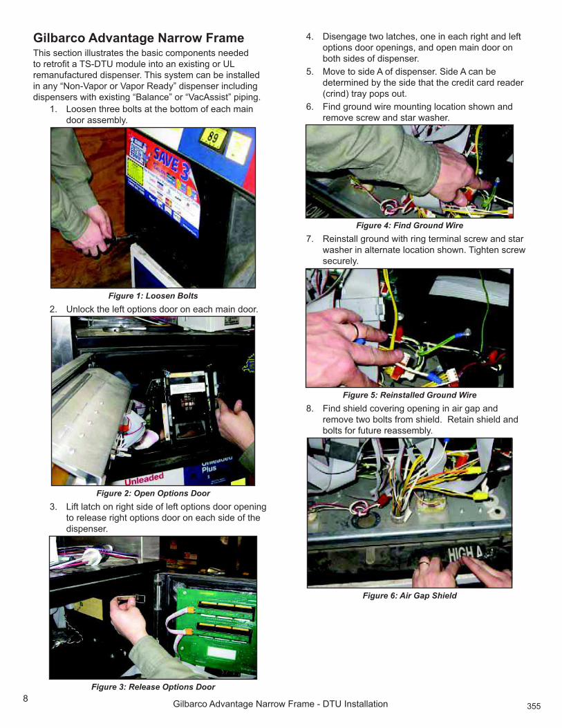
5% Y6H&%+(&K2%7)%06J2&%164A%7H%+AH&%7S&67)1%4770%7SA)6)J%
to release right options door on each side of the
dispenser.
Figure 3: Release Options Door
!5% ]61A)J(JA%&G7%+(&K2A18%7)A%6)%A(K2%06J2&%()4%+AH&%
options door openings, and open main door on
both sides of dispenser.
;5% '7UA%&7%164A%?%7H%461SA)1A05%>64A%?%K()%TA%
determined by the side that the credit card reader
(crind) tray pops out.
.5% E6)4%J07*)4%G60A%L7*)&6)J%+7K(&67)%127G)%()4%
0AL7UA%1K0AG%()4%1&(0%G(12A05
Figure 4: Find Ground Wire
-5% 3A6)1&(++%J07*)4%G6&2%06)J%&A0L6)(+%1K0AG%()4%1&(0%
G(12A0%6)%(+&A0)(&A%+7K(&67)%127G)5%@6J2&A)%1K0AG%
securely.
Figure 5: Reinstalled Ground Wire
"5% E6)4%126A+4%K7UA06)J%7SA)6)J%6)%(60%J(S%()4%
0AL7UA%&G7%T7+&1%H07L%126A+45%%3A&(6)%126A+4%()4%
bolts for future reassembly.
Figure 6: Air Gap Shield

;.9
_6+T(0K7%?4U()&(JA%`(007G%E0(LA%\%]@=%:)1&(++(&67)
#5% 3AL7UA%&G7%1K0AG1%H07L%*SSA0%(60%J(S%I)7KI\7*&%
K7UA0%()4%0AL7UA5%%]61K(04%K7UA0%T*&%IAAS%1K0AG1%
for reuse.
Figure 7: Remove Screws
</5%3AL7UA%&G7%1K0AG1%H07L%+7GA0%(60%J(S%I)7KI7*&%
K7UA0%()4%0AL7UA5%%]61K(04%K7UA0%()4%1K0AG15
<<5% 3AL7UA%+7GA0%4770%H07L%164A%?%7H%461SA)1A0%*16)J%
key lock on right side of door. Save door for future
reassembly
<D5%E6)4%S7&&A4%)6SS+A%(11ALT+M8%< <.</5%3AL7UA%(++%
G(12A01%()4%)*&1%()4%1A&%(164A5%
< 5%b*++%G60A1%H07L%&7S%164A%7H%S7&&A4%)6SS+A%(11ALT+M%
through dispenser hydraulics enclosure up through
7SA)6)J%6)%+7GA0%(60%J(S%I)7KI\7*&5
Figure 8: Potted Conduit wires
<!5%?&&(K2%7)A%)*&%()4%G(12A0%7)&7%&2A%S7&&A4%)6SS+A%
(11ALT+M%TAH70A%S*126)J%G60A1%*S%&207*J2%A+AK&06K(+%
enclosure.
<;5%b*++%G60A1%()4%&2A)%)6SS+A%(11ALT+M%*S%6)&7%A+AK&07)6K1%
A)K+71*0A5%E6&%G(12A0%()4%)*&%7UA0%G60A1%()4%&6J2&A)%
)*&%1AK*0A+M%6)%S+(KA8%(1%127G)%6)%E6J*0A%#5
Figure 9: Potted Nipple Installed
<.5%3A(&&(K2%(60%J(S%126A+4%*16)J%1K0AG1%S0AU67*1+M%
retained in step 8.
<-5%3A6)1&(++%&2A%1K0AG1%S0AU67*1+M%0A&(6)%6)%1&AS%#5%%
@2A1A%1K0AG1%1A(+%&2A%27+A1%+AH&%TA26)4%TM%&2A%(60%
gap knockout.
<"5%E6)4%@>\]@=%P%b%I6&%()4%0AL7UA%T0(KIA&18%]@=8%
()4%2(04G(0A%H07L%T7F5%
19. Remove cover from DTU.
D/5% :)1&(++%L7*)&6)J%T0(KIA&%&7%]@=%G6&2%&G7%1K0AG18%
)*&1%()4%G(12A01%H07L%2(04G(0A%S07U64A4%G6&2%
]@=%(1%4A1K06TA4%6)%&2A%_A)A0(+%:)H70L(&67)%
section. Ensure that bracket is installed on correct
164A%(1%127G)5
Figure 10: Mounting Bracket on DTU
D<5%3AL7UA%&G7%1K0AG1%H07L%:>%G606)J%K7UA0%6)164A%
the DTU and remove cover. Retain cover and
1K0AG1%H70%0A(11ALT+M
DD5%E6)4%&2A%#/%4AJ0AA%$%&&6)J%H07L%:>%G606)J%I6&8%
/D/\<;< 5%3AL7UA%)*&%H07L%#/%4AJ0AA%$ tting.
Attach $%&&6)J%&7%7SA)6)J%)A(0A1&%:>%G606)J%&A0L6)(+%
block of DTU using nut previously removed.
D 5%E6)4%S7GA0%2(0)A11%I6&%S(0&%)*LTA0%.//\/<."5%
E6)4%&2A%_6+T(0K7%?4U()&(JA%S7GA0%2(0)A11%()4%
J07*)4%G6&2%06)J%&A0L6)(+%(1%127G)%6)%$%J*0A%!%7H%
&2A%b(0&1%Y61&5%
D!5%b*&%G606)J%2(0)A11%A)4%G6&2%K06LS%K7))AK&70%
through opening in DTU nearest terminal block
k<5%?&&(K2%G26&A%+A(4%&7%&A0L6)(+%T+7KI%S716&67)%
+(TA+A4%`a=@3?Y%()4%T+(KI%+A(4%&7%&A0L6)(+%
T+7KI%S716&67)%+(TA+A4%Y<%7)%&A0L6)(+%T+7KI%k<%7H%
]@=5%?&&(K2%J07*)4%G60A%&7%&A0L6)(+%T+7KI%S716&67)%
+(TA+A4%_`]%7H%kD%7)%]@=5
Figure 11: DTU Power Connections
D;5%'7UA%]@=%(11ALT+M%&7%461SA)1A0%)A(0A1&%
intended mounting location

;-10
_6+T(0K7%?4U()&(JA%`(007G%E0(LA%\%]@=%:)1&(++(&67)
D.5%E6)4%0A4*KA0%H07L%:>%G606)J%I6&8%/D/\<;< 5%%E07L%
A+AK&06K(+%A)K+71*0A8%S*++%G60A1%H07L%S7&&A4%)6SS+A%
(11ALT+M%&207*J2% P![%7SA)6)J%7H%0A4*KA0%()4%
attach reducer to the top of the nipple assembly.
D-5%E6)4%1&0(6J2&%K7)4*6&%$%&&6)J%H07L%:>%G606)J%I6&8%
/D/\<;< 5%%E07L%A+AK&06K(+%A)K+71*0A8%S*++%G60A1%
from the potted nipple assembly through opening
of straight conduit $ tting. Attach straight conduit
$ tting onto the reducer.
28. Remove nut and bushing from straight conduit
$ tting. Place bushing on one end of V exible
K7)4*6&5%b*12%G60A1%H07L%)6SS+A%(11ALT+M%&207*J2%
T*126)J%P%V exible conduit and secure V exible
conduit to straight conduit $ tting using nut.
Figure 12: Attaching Flexible Conduit
29. Remove nut and bushing from 90 degree conduit
$ tting and push V exible conduit through nut. Put
bushing on unattached end of V exible conduit.
b*12%G60A1%H07L%V exible conduit through the 90
degree conduit $%&&6)J%()4%S*++%AFKA11%G60A%6)&7%
DTU. Attach V exible conduit to 90-degree $ tting
G6&2%)*&5
Figure 13: Attach Flexible Conduit to DTU
/5%c*&%AFKA11%G60A%6)164A%]@=%(++7G6)J%(%+A)J&2%7H%D[%
H70%&A0L6)(+%T+7KI%G606)J5%>&06S%6)1*+(&67)% P8” from
A)41%7H%G60A5%?&&(K2%G60A1%&7%]@=%&A0L6)(+%T+7KI%
(1%H7++7G1%N]:?_3?'O
Figure 14: Attach Wiring to DTU
<5%3A6)1&(++%T(006A0%K7UA0%*16)J%1K0AG1%&2(&%GA0A%
0AL7UA4%6)%1&AS%D 5
D5%3AS+(KA%]@=%K7UA05%
5% :)1&(++%&2A%]@=%(11ALT+M%7)%&2A%2706W7)&(+%K0711%
T0(KIA&%(1%127G)%6)%E6J*0A%<;5%%=1A%&2A%&G7%
1K0AG18%G(12A018%()4%)*&1%(1%1*SS+6A4%6)%&2A%@>\
]@=Pb%2(04G(0A%I6&5
Figure 15: Attach DTU Mounting Bracket
!5%E6)4%6)S*&%K7))AK&70%7)%?c%461&06T*&67)%G606)J%
harness and disconnect.
;5% :)1A0&%)AG%S7GA0%2(0)A11%G6&2%HA006&A1%TA&GAA)%
6)S*&%S7GA0%()4%?c%461&06T*&67)%2(0)A115
Figure 16: Connecting to Dispenser Power

;"11
_6+T(0K7%?4U()&(JA%`(007G%E0(LA%\%]@=%:)1&(++(&67)
.5%?&&(K2%06)J%&A0L6)(+%7H%]@=%J07*)4%G60A%&7%
461SA)1A0%G6&2%T7+&8%)*&%()4%1&(0%G(12A05
Figure 17: Attach Ground Wire
-5%=1A%G60A\G0(S%&6A1%&7%(&&(K2%AFKA11%G60A1%H07L%?c%
G606)J%2(0)A11%&7JA&2A05
"5%=1A%G60A\G0(S%&6A1%&7%(&&(K2%AFKA11%G60A%H07L%]@=%
S7GA0%2(0)A11%()4%J07*)4%(G(M%H07L%4770%()4%
gears.
#5%E6)4%K(T+A%(11ALT+M%AF&A)46)J%H07L%@>\^E'%
vapor meter in dispenser hydraulics enclosure.
!/5%E6)4%G606)J%H07L%S0AU67*1+M%6)1&(++A4%S7&&A4%)6SS+A%
assembly inside hydraulics enclosure.
!<5% E6)4%&G7%G60A\1S+6KA%K7))AK&70%I6&15%:)164A%2M40(*+6K1%
A)K+71*0A8%K7))AK&%T+(KI%G60A%H07L%S7&&A4%)6SS+A%
(11ALT+M%&7%T+(KI%G60A%H07L%@>\^E'%V%7G%LA&A0%TM%
S+(K6)J%A(K2%+A(4%6)&7%()%7SA)6)J%6)%&2A%G60A%1S+6KA%
connector and push $ tting closed to lock.
!D5%E6)4%K(T+A%AF&A)46)J%H07L%@>\^b>%6)164A%
2M40(*+6K1%A)K+71*0A5%c*&%MA++7G%()4%T+*A%+A(41%
from end of cable.
! 5%E6)4%S*0S+A%()4%G26&A%G60A1%H07L%S7&&A4%)6SS+A%
(11ALT+M%6)%2M40(*+6K1%A)K+71*0A5%>&06S%G606)J%
insulation P8g%H07L%A)4%7H%G60A5
!!5%=16)J%G60A%)*&1%S07U64A4%G6&2%I6&8%(&&(K2%S*0S+A%
G60A%H07L%S7&&A4%)6SS+A%(11ALT+M%&7%T+(KI%G60A%
7H%@>\^b>%()4%G26&A%G60A%H07L%S7&&A4%)6SS+A%
(11ALT+M%&7%G26&A%G60A%7H%&2A%@>\^b>5
!;5%c+71A%L(6)%47701%7)%>64A%?%()4%>64A%f5
!.5%a)J(JA%L(6)%4770%+(&K2A1%+7K(&A4%6)%T7&2%7S&67)%
openings for each side. Refer to $%J*0A%D%j% 5
!-5%@6J2&A)%&2A%&20AA%T7+&1%(&%&2A%T7&&7L%7H%A(K2%L(6)%
door assembly. See $ gure 1.
!"5%3A6)1&(++%164A%?%+7GA0%461SA)1A0%47705%%E60L+M%
attach using key lock on right side of door.

;#12
_6+T(0K7%a)K70A% //%()4%;//%\%]@=%:)1&(++(&67)
Gilbarco Encore 300 and 500 SeriesThis section illustrates the basic components needed
to retro$ t a TS-DTU module into an existing dispenser.
@261%1M1&AL%K()%TA%6)1&(++A4%6)%()M%Z`7)\^(S70%70%^(S70%
3A(4M[%461SA)1A0%6)K+*46)J%461SA)1A01%G6&2%AF61&6)J%
“Balance” or “VacAssist” piping.
1. Unlock interface doors on both sides of dispenser.
dSA)%&G7%+(&K2A1%7)%+AH&%164A%7H%6)&A0H(KA%4770%()4%
open main doors.
Figure 1: Open Doors
D5% E6)4%@>\]@=Pb%H07L%I6&%()4%0AL7UA%T0(KIA&18%
]@=8%()4%2(04G(0A%H07L%T7F5
5% 3AL7UA%K7UA0%H07L%]@=5
!5% :)1&(++%L7*)&6)J%T0(KIA&%&7%]@=%*16)J%&G7%1K0AG18%
)*&1%()4%G(12A01%H07L%2(04G(0A%S07U64A4%G6&2%
]@=%(1%4A1K06TA4%6)%&2A%_A)A0(+%:)H70L(&67)%
1AK&67)5%'(IA%1*0A%&2A%T0(KIA&%61%6)1&(++A4%7)%
K700AK&%164A%(1%127G)5%
Figure 2: Install Mounting Bracket
;5% :)1&(++%&2A%]@=%(11ALT+M%7)%&2A%2706W7)&(+%
K0711%T0(KIA&%(1%127G)%6)%E6J*0A% 5%%=1A%
&2A%&G7%1K0AG18%G(12A018%()4%)*&1%(1%
1*SS+6A4%6)%&2A%@>\]@=Pb%2(04G(0A%I6&5
Figure 3: Mount DTU in Dispenser
.5% E6)4%S7GA0%2(0)A11%I6&%S(0&%)*LTA08%.//\/<.-5%E6)4%
&2A%_6+T(0K7%S7GA0%2(0)A11%(1%127G)%6)%$%J*0A%!%7H%
&2A%b(0&1%Y61&5%3AL7UA%&6A\G0(S1%()4%*)K76+5%@2A%
_6+T(0K7%K(T+A%G6++%2(UA%J0AA)%J07*)4%G60A5%
7. Inside dispenser, $%)4%&2A%6)K7L6)J%S7GA0%
K7))AK&67)5%?&&(K2%&2A%)AG%S7GA0%AF&A)167)%
K(T+A%TA&GAA)%&2A%706J6)(+%461SA)1A0%S7GA0%
K7))AK&7015%`7&6KA%&2(&%&2A%G60A%K7+701%
L(&K2%*S%G6&2%&2A%706J6)(+%K7))AK&67)5
Figure 4: Power Distribution Wires
"5% c(0AH*++M%07*&A%]@=%S7GA0%G606)J%2(0)A11%&7%]@=5
Figure 5: Power Wiring
9. Route crimp terminal end of harness through
opening in the bottom of the DTU and connect
G26&A%+A(4%&7%&A0L6)(+%T+7KI%S716&67)%+(TA+A4%
`a=@3?Y%()4%T+(KI%+A(4%&7%&A0L6)(+%T+7KI%
S716&67)%+(TA+A4%Y<%7)%&A0L6)(+%T+7KI%k<%7H%]@=5

./<
_6+T(0K7%a)K70A% //%()4%;//%\%]@=%:)1&(++(&67)
Figure 6: Connect Power Leads
</5%E6)4%J07*)4%G60A%H07L%S7GA0%2(0)A11%I6&%
.//\/<.;5%3AL7UA%&6A1%()4%*)K76+5%E07L%A)4%
G6&27*&%06)J%K76+8%1&06S%6)1*+(&67)% P"[%H07L%A)4%7H%
G60A5
<<5% 37*&A%J07*)4%G60A%A)4%G6&2%7*&%06)J%&A0L6)(+%
through DTU and secure to terminal block.
<D5%?&&(K2%06)J%&A0L6)(+%7H%J07*)4%G60A%&7%461SA)1A0%
T0(KIA&%*16)J%1K0AG%()4%)*&%(1%127G)5%c76+%
AFKA11%G606)J%()4%&6A%6&%&7%A)1*0A%&2(&%6&%47A1%)7&%
6)&A0HA0A%G6&2%4770%K+716)J5
Figure 7: Attach Ground Wire
< 5%E6)4%164A%7H%461SA)1A0%7SS716&A%7H%S7GA0%1*SS+M5%
3AL7UA%+7GA0%4770%7)%&2(&%164A%7H%461SA)1A0%TM%
+771A)6)J%&G7%1K0AG15
<!5%3AL7UA%+7GA0%47701%7)%T7&2%164A1%7H%461SA)1A015%
Set doors aside and save for later assembly
<;5%E6)4%I)7KI7*&%S()A+%7)%&2A%T7&&7L%7H%&2A%A+AK&06K(+%
A)K+71*0A%K+71A1&%&7%&2A%]@=%N>AA%E6J*0A%-O5
<.5%=16)J%1K0AG406UA08%0AL7UA%7)A%I)7KI7*&%S+*J%H07L%
knockout panel.
<-5%E6)4%%S7&&A4%)6SS+A%(11ALT+M8%< <.</5%
=)47%G60A%&6A1%()4%*)K76+%G606)J5
18. Remove top nut from potted nipple and remove
7)A%G(12A0%TM%S*++6)J%7UA0%G60A%+A(415%eAAS%)*&%
()4%G(12A0%H70%H*&*0A%*1A5
<#5%b*++%G60A1%H07L%&7S%7H%S7&&A4%)6SS+A%(11ALT+M%*S%
&207*J2%&2A%7SA)6)J%K0A(&A4%6)%1&AS%<.%H07L%&2A%
hydraulics enclosure to the electrical enclosure.
a)1*0A%&2(&%G606)J%61%)7&%4(L(JA4%TM%12(0S%A4JA15
Figure 8: Pulling Wires Through Opening
20. Pull top of potted nipple assembly through the
T7&&7L%7H%&2A%A+AK&06K(+%A)K+71*0A%(1%127G)%6)%
E6J*0A%#5
Figure 9: Potted Nipple in Position
D<5%b*&%G60A1%6)%A+AK&06K(+%A)K+71*0A%&207*J2%G(12A0%
()4%)*&%&2(&%GA0A%0AL7UA4%H07L%S7&&A4%)6SS+A%
assembly in step 18.
22. Tighten nut to tightly hold potted nipple assembly.
D 5%E6)4%0A4*KA0%H07L%:>%G606)J%I6&8%/D/\<;< 5%E07L%
A+AK&06K(+%A)K+71*0A8%S*++%G60A1%H07L%&2A%S7&&A4%
nipple assembly through ¾” opening of reducer
and attach reducer to the top of the nipple
assembly.

.<<!
_6+T(0K7%a)K70A% //%()4%;//%\%]@=%:)1&(++(&67)
D!5%E6)4%1&0(6J2&%K7)4*6&%$%&&6)J%H07L%:>%G606)J%I6&%
/D/\<;< 5%E07L%A+AK&06K(+%A)K+71*0A8%S*++%G60A1%
from the potted nipple assembly through opening
of straight conduit $ tting. Attach straight conduit
$%&&6)J%7)&7%&2A%0A4*KA05%3AHA0%&7%E6J*0A%</5
Figure 10: Reducer Installed
D;5%3AL7UA%&G7%1K0AG1%H07L%:>%G606)J%K7UA0%6)164A%
the DTU and remove cover. Keep cover and
1K0AG1%H70%H*&*0A%0A(11ALT+M5
D.5%E6)4%&2A%#/\4AJ0AA%$%&&6)J%H07L%:>%G606)J%I6&8%
/D/\<;< 5%3AL7UA%)*&%H07L%#/\4AJ0AA%$ tting.
Attach $ tting to opening of DTU nearest the IS
connector using nut previously removed.
Figure 11: 90-degree Fitting Installed
D-5%E6)4%&2A%V exible conduit from the IS Wiring Kit,
/D/\<;< 5%=16)J%#/\4AJ0AA%$ tting and straight
$ tting installed earlier, determine length of V exible
conduit assembly needed and cut to $ t. Refer to
E6J*0A%<D5%
Figure 12: Flexible Conduit Installation
D"5%b*++%G60A1%H07L%S7&&A4%)6SS+A%(11ALT+M%&207*J2%
V exible conduit.
29. Remove nut and bushing from straight conduit
$ tting.
/5%b*12%T*126)J%7)&7%A)4%7H%V exible conduit and
reattach to straight $ tting using nut.
<5%3AL7UA%T*126)J%()4%)*&%H07L%#/\4AJ0AA%K7)4*6&%
$%&&6)J%7)%]@=%()4%S*++%G606)J%P%V exible conduit
through.
D5%37*&A%G60A1%&207*J2%#/\4AJ0AA%K7)4*6&%$ tting and
pull into the DTU enclosure.
Figure 13: Wires in Flexible Conduit
5%=16)J%)*&%()4%&2A)%T*126)J8%(&&(K2%V exible conduit
to 90-degree conduit $ tting.

.D15
_6+T(0K7%a)K70A% //%()4%;//%\%]@=%:)1&(++(&67)
!5%c*&%AFKA11%G60A%6)164A%]@=%(++7G6)J%(%+A)J&2%7H%
D[%H70%&A0L6)(+%T+7KI%G606)J5%>&06S%G60A%6)1*+(&67)%
P"[%H07L%&2A%A)45%c7))AK&%G60A1%&7%]@=%&A0L6)(+%
block.
Figure 14: Wiring Connection to DTU
;5%3A6)1&(++%T(006A0%K7UA0%*16)J%1K0AG1%H07L%1&AS%D 5
Figure 15: Reinstall Barrier
.5%3AS+(KA%]@=%K7UA05
Figure 16: Replace Cover
-5%E6)4%K(T+A%(11ALT+M%AF&A)46)J%H07L%@>\^E'%
vapor meter in dispenser hydraulics enclosure.
"5%E6)4%G606)J%H07L%S0AU67*1+M%6)1&(++A4%S7&&A4%)6SS+A%
assembly inside hydraulics enclosure.
#5%E6)4%&G7%G60A%1S+6KA%K7))AK&70%I6&15%:)164A%
2M40(*+6K1%A)K+71*0A%K7))AK&%T+(KI%G60A%H07L%
S7&&A4%)6SS+A%(11ALT+M%&7%T+(KI%G60A%H07L%@>\^E'%
V%7G%LA&A0%TM%S*&&6)J%A(K2%+A(4%6)&7%()%7SA)6)J%6)%
&2A%G60A%1S+6KA%K7))AK&70%()4%S*12%$ tting closed to
lock.
!/5%E6)4%K(T+A%AF&A)46)J%H07L%@>\^b>%6)164A%
2M40(*+6K1%A)K+71*0A5%c*&%MA++7G%()4%T+*A%+A(41%
from end of cable.
!<5%E6)4%S*0S+A%()4%G26&A%G60A1%H07L%S7&&A4%)6SS+A%
(11ALT+M%6)%2M40(*+6K1%A)K+71*0A5%>&06S%G606)J%
6)1*+(&67)% P"[%H07L%A)4%7H%G60A5
!D5%=16)J%G60A%)*&1%S07U64A4%G6&2%I6&8%(&&(K2%S*0S+A%
G60A%H07L%S7&&A4%)6SS+A%(11ALT+M%&7%T+(KI%G60A%
7H%@>\^b>%()4%G26&A%G60A%H07L%S7&&A4%)6SS+A%
(11ALT+M%&7%G26&A%G60A%7H%&2A%@>\^b>5
! 5%?&&(K2%+7GA0%2M40(*+6K1%K7UA01%&7%461SA)1A0%()4%
secure each using key lock.
!!5%c+71A%T7&2%L(6)%47701%7H%461SA)1A05%%>AK*0A+M%
(&&(K2%&2A%&G7%+(&K2A1%7)%&2A%+AH&%164A%7H%A(K2%
interface door.
!;5%c+71A%T7&2%6)&A0H(KA%47701%()4%+7KI5

. <.
Tokheim Premier B DTU Installation
>3$7)&/'E!)/&)!'B'FGHHBIThis section illustrates the basic components needed
to retro$ t a TS-DTU module into an existing dispenser.
@261%1M1&AL%K()%TA%6)1&(++A4%6)%()M%Z`7)\^(S70%70%^(S70%
3A(4M[%461SA)1A0%6)K+*46)J%461SA)1A01%G6&2%AF61&6)J%
“Balance” or “VacAssist” piping.
`7&AB% c7)4*6&%I)7KI7*&1%LA(1*0A%<%<P
.!17
Tokheim Premier B DTU Installation
10. Using a ¾” conduit hole punch, open hole
previously drilled.
Figure 6: Use Hole Punch
<<5% E6)4%%S7&&A4%)6SS+A%(11ALT+M8%< <.</5%
=)47%G60A%&6A1%()4%*)G6)4%G606)J5
<D5% 3AL7UA%()4%461S71A%7H%0*TTA0%G(12A0%H07L%
assembly.
< 5% 3AL7UA%&7S%)*&%()4%G(12A0%H07L%S7&&A4%)6SS+A5%
eAAS%)*&%()4%G(12A0%H70%H*&*0A%*1A5
<!5% b*++%G60A1%H07L%&7S%7H%S7&&A4%)6SS+A%(11ALT+M%*S%
from the hydraulics enclosure to the electrical
A)K+71*0A5%'(IA%1*0A%G606)J%61%)7&%4(L(JA4%TM%
sharp edges.
15. Pull top of potted nipple assembly through opening
6)%A+AK&06K(+%A)K+71*0A5%b*12%G60A1%6)164A%A+AK&06K(+%
A)K+71*0A%&207*J2%G(12A0%()4%)*&%0A&(6)A4%6)%1&AS%
< 5%>AK*0A+M%(&&(K2%S7&&A4%)6SS+A%(11ALT+M%TM%
tightening nut.
Figure 7: Potted Nipple Assembly Attached
<.5% E6)4%0A4*KA0%H07L%:>%G606)J%I6&%/D/\<;< 5%E07L%
A+AK&06K(+%A)K+71*0A8%S*++%G60A1%H07L%&2A%S7&&A4%
nipple assembly through ¾” opening of reducer
and thread reducer to the top of the nipple
assembly.
<-5% E6)4%1&0(6J2&%K7)4*6&%$%&&6)J%H07L%:>%G606)J%I6&5%E07L%
A+AK&06K(+%A)K+71*0A8%S*++%G60A1%H07L%&2A%S7&&A4%
nipple assembly through opening of straight
conduit $ tting. Attach straight conduit $ tting onto
the reducer.
<"5% E6)4%@>\]@=Pb%I6&%()4%0AL7UA%T0(KIA&18%]@=8%
and fasteners from box.
19. Remove cover from DTU.
Figure 8: DTU Open
D/5% :)1&(++%L7*)&6)J%T0(KIA&%&7%]@=%G6&2%&G7%1K0AG18%
)*&1%()4%G(12A01%H07L%2(04G(0A%S07U64A4%G6&2%
]@=%(1%4A1K06TA4%6)%&2A%_A)A0(+%:)H70L(&67)%
section. Ensure that bracket is installed on correct
164A%(1%127G)5
D<5% 3AL7UA%&G7%1K0AG1%H07L%:>%G606)J%K7UA0%6)164A%
the DTU and remove cover. Retain cover and
1K0AG1%H70%H*&*0A%0A(11ALT+M
DD5% E6)4%#/\4AJ0AA%$%&&6)J%H07L%:>%G606)J%I6&5%3AL7UA%
nut from 90-degree $ tting. Attach $ tting to opening
)A(0A1&%:>%G606)J%&A0L6)(+%T+7KI%7H%]@=%*16)J%)*&%
previously removed.
Figure 9: Attach 90-degree Fitting
D 5% E6)4%S7GA0%2(0)A11%I6&%S(0&%)*LTA0%.//\/<.;5%
E6)4%&2A%@7I2A6L%S7GA0%2(0)A11%()4%J07*)4%G60A%
G6&2%06)J%&A0L6)(+%(1%127G)%6)%$%J*0A%!%7H%&2A%b(0&1%
Y61&5%3AL7UA%&6A\G0(S1%()4%*)K76+5%
D!5% 37*&A%G606)J%2(0)A11%A)4%G6&2%K06LS%K7))AK&70%
through opening in DTU nearest terminal block
k<5%?&&(K2%G26&A%+A(4%&7%&A0L6)(+%T+7KI%S716&67)%
+(TA+A4%`a=@3?Y%()4%T+(KI%+A(4%&7%&A0L6)(+%
T+7KI%S716&67)%+(TA+A4%Y<%7)%&A0L6)(+%T+7KI%k<%7H%
]@=5%?&&(K2%J07*)4%G60A%&7%&A0L6)(+%T+7KI%S716&67)%
+(TA+A4%_`]%7H%kD%7)%]@=5

.;18
Tokheim Premier B DTU Installation
25. Remove nut and bushing from straight conduit
$ tting. Place bushing on one end of V exible
K7)4*6&5%b*12%G60A1%H07L%)6SS+A%(11ALT+M%&207*J2%
T*126)J%P%V exible conduit and attach V exible conduit
to straight conduit $ tting using nut.
Figure 10: Attach Flexible Conduit to Potted Nipple
D.5% 3AL7UA%)*&%()4%T*126)J%H07L%#/\4AJ0AA%K7)4*6&%
$ tting and pull V exible conduit through nut. Attach
bushing on unattached end of V exible conduit. Pull
G60A1%H07L%V exible conduit through the 90-degree
conduit $%&&6)J%()4%S*++%AFKA11%G60A%6)&7%]@=5
27. Attach V exible conduit to 90-degree $%&&6)J%G6&2%)*&5
Figure 11: Attach Flexible Conduit to 90-Degree Fitting
D"5% c*&%AFKA11%G60A%6)164A%]@=%(++7G6)J%(%+A)J&2%7H%
D[%H70%&A0L6)(+%T+7KI%G606)J5%>&06S%G60A%6)1*+(&67)%
P"l%H07L%&2A%A)41%7H%G60A5%?&&(K2%G60A1%&7%]@=%
&A0L6)(+%T+7KI%(1%H7++7G15
Figure 12: Wiring Connection to DTU
D#5% 3A6)1&(++%T(006A0%K7UA0%*16)J%1K0AG1%*)6)1&(++A4%6)%
1&AS%D 5
Figure 13: Reinstall Barrier Cover
/5% 3AS+(KA%]@=%K7UA05
<5% :)1&(++%&2A%]@=%(11ALT+M%7)%&2A%461SA)1A0%UA0&6K(+%
T0(KIA&%(1%127G)%6)%E6J*0A%<!5%%=1A%&2A%&G7%
1K0AG18%G(12A018%()4%)*&1%(1%1*SS+6A4%6)%&2A%@>\
]@=Pb%2(04G(0A%I6&5
Figure 14: DTU Attached to Dispenser

..19
Tokheim Premier B DTU Installation
D5% 37*&A%S7GA0%K(T+A%(+7)J%T7&&7L%7H%A+AK&06K(+%
A)K+71*0A%()4%(&&(K2%&7%?c%S7GA0%461&06T*&67)%
T7(04%(1%127G)5%a)1*0A%&2(&%G606)J%61%IAS&%(G(M%
H07L%12(0S%A4JA1%()4%G6++%)7&%6)&A0HA0A%G6&2%4770%
closing.
5% b+*J%&2A%K7))AK&70%H07L%&2A%@7I2A6L%S7GA0%
2(0)A11%6)&7%(U(6+(T+A%K7))AK&70%7)%?c%S7GA0%
distribution board.
Figure 15: Connect to AC Power Board
!5%?&&(K2%06)J%&A0L6)(+%7H%J07*)4%G60A%&7%461SA)1A0%
T0(KIA&%*16)J%1K0AG%()4%)*&%(1%127G)5%c76+%
AFKA11%G606)J%()4%1AK*0A%G6&2%&6A\G0(S1%&7%A)1*0A%
&2(&%6&%47A1%)7&%6)&A0HA0A%G6&2%4770%K+716)J5%
Figure 16: Attach Ground Wire
;5%E6)4%K(T+A%(11ALT+M%AF&A)46)J%H07L%@>\^E'%6)%
dispenser hydraulics enclosure.
.5%E6)4%G606)J%H07L%S0AU67*1+M%6)1&(++A4%S7&&A4%)6SS+A%
assembly inside hydraulics enclosure.
-5% E6)4%&G7%G60A%1S+6KA%K7))AK&70%I6&15%:)164A%
2M40(*+6K1%A)K+71*0A8%K7))AK&%T+(KI%G60A%H07L%
S7&&A4%)6SS+A%(11ALT+M%&7%T+(KI%G60A%H07L%@>\^E'%
V%7G%LA&A0%TM%S*&&6)J%A(K2%+A(4%6)&7%()%7SA)6)J%6)%
&2A%G60A%1S+6KA%K7))AK&70%()4%S*12%$ tting closed to
lock.
-5% E6)4%K(T+A%AF&A)46)J%H07L%@>\^b>%6)164A%
2M40(*+6K1%A)K+71*0A5%c*&%MA++7G%()4%T+*A%+A(41%
from end of cable.
-5% E6)4%S*0S+A%()4%G26&A%G60A1%H07L%S7&&A4%)6SS+A%
(11ALT+M%6)%2M40(*+6K1%A)K+71*0A5%>&06S%G606)J%
6)1*+(&67)% P"[H07L%A)4%7H%G60A5
!/5% =16)J%G60A%)*&1%S07U64A4%G6&2%I6&8%(&&(K2%S*0S+A%
G60A%H07L%S7&&A4%)6SS+A%(11ALT+M%&7%T+(KI%G60A%
7H%@>\^b>%()4%G26&A%G60A%H07L%S7&&A4%)6SS+A%
(11ALT+M%&7%G26&A%G60A%7H%&2A%@>\^b>5
%!<5% 3AS+(KA%+7GA0%2M40(*+6K1%4770%&7%164A%?%()4%+7KI%
G6&2%IAM5
%!D5% Y6H&%&2A%461S+(M%(11ALT+M%T(KI%&7%)70L(+%S716&67)%
()4%&6J2&A)%G6&2%&G7%(&&(K2A4%1K0AG15
%! 5% Y7KI%+(&K2%7)%461S+(M%K7UA0%7)%f%164A%7H%461SA)1A05
%!!5% c+71A%06J2&%7S&67)1%4770%7)%f%164A%()4%+7KI5
%!;5% c+71A%S06)&A0%4770%7)%f%164A%()4%+7KI5
%!.5% c+71A%06J2&%7S&67)1%4770%7)%?%164A%()4%+7KI5

.-20
@7I2A6L%b0AL6A0%c%]@=%:)1&(++(&67)
>3$7)&/'E!)/&)!'JThis section illustrates the basic components needed
to retro$ t a TS-DTU module into an existing dispenser.
@261%1M1&AL%K()%TA%6)1&(++A4%6)%()M%Z`7)\^(S70%70%^(S70%
3A(4M[%461SA)1A0%6)K+*46)J%461SA)1A01%G6&2%AF61&6)J%
“Balance” or “VacAssist” piping.
1. Unlock left door from each side of dispenser and
open the door.
Figure 1: Unlock Door
2. Release inside latch from left door assembly and
open center door.
Figure 2: Release Inside Latch
5% 3ASA(&%1&AS%D%H70%06J2&%4770%(11ALT+M5
Figure 3: Right Door Assembly
!5% E6)4%164A%f%7H%461SA)1A05%>64A%f%G6++%TA%&2A%164A%
G6&27*&%&2A%?c%461&06T*&67)%T7(045%=)6&%G6++%TA%
installed on the right side of side B
;5% E6)4%@>\]@=Pb%I6&%()4%0AL7UA%T0(KIA&18%]@=8%
and fasteners from box.
.5% 3AL7UA%K7UA0%H07L%]@=5
-5% :)1&(++%L7*)&6)J%T0(KIA&%&7%]@=%G6&2%&G7%1K0AG18%
)*&1%()4%G(12A01%H07L%2(04G(0A%S07U64A4%G6&2%
]@=%(1%4A1K06TA4%6)%&2A%_A)A0(+%:)H70L(&67)%
section. Ensure that bracket is installed on correct
164A%(1%127G)5
Figure 4: Attaching DTU
"5% 3AL7UA%&G7%1K0AG1%H07L%:>%G606)J%K7UA0%6)164A%
the DTU and remove cover. Keep cover and
1K0AG1%H70%H*&*0A%0A(11ALT+M5
#5% E6)4%#/\4AJ0AA%$%&&6)J%H07L%:>%G606)J%I6&%/D/\<;< 5%
Remove nut from 90 degree $ tting. Attach $ tting to
7SA)6)J%)A(0A1&%:>%G606)J%&A0L6)(+%T+7KI%7H%]@=%
using nut previously removed.
</5%E6)4%S7GA0%2(0)A11%I6&%S(0&%)*LTA0%.//\/<.;5%
E6)4%&2A%@7I2A6L%S7GA0%2(0)A11%()4%J07*)4%G60A%
G6&2%06)J%&A0L6)(+%(1%127G)%6)%$%J*0A%!%7H%&2A%b(0&1%
Y61&5%3AL7UA%&6A\G0(S1%()4%*)K76+5
<<5% b*++%G606)J%2(0)A11%A)4%G6&2%K06LS%K7))AK&70%
through opening in DTU nearest terminal block
k<5%?&&(K2%G26&A%+A(4%&7%&A0L6)(+%T+7KI%S716&67)%
+(TA+A4%`a=@3?Y%()4%T+(KI%+A(4%&7%&A0L6)(+%
T+7KI%S716&67)%+(TA+A4%Y<%7)%&A0L6)(+%T+7KI%k<%7H%
]@=5%?&&(K2%J07*)4%G60A%&7%&A0L6)(+%T+7KI%S716&67)%
+(TA+A4%_`]%7H%kD%7)%]@=5
<D5%E6)4%U(S70%T(006A0%S+*J%7)%T7&&7L%7H%461SA)1A0%
electronics barrier enclosure.
< 5%3AL7UA%+7GA0%4770%7)%164A%?%7H%461SA)1A0%N164A%
G6&2%?c%461&06T*&67)%T7(04O5
Figure 5: Remove Lower Door

."21
@7I2A6L%b0AL6A0%c%]@=%:)1&(++(&67)
<!5%3AL7UA%)*&%H07L%&7S%7H%S+*J%*16)J%G0A)K25
<;5%3AL7UA%S+*J8%G(12A018%()4%)*&1%()4%461K(04%(++%
2(04G(0A5
Figure 6: Remove Nut
<.5%E6)4%S7&&A4%)6SS+A%(11ALT+M%< <.</5%
=)&6A%G60A%&6A1%()4%*)G6)4%G606)J5
<-5%3AL7UA%()4%461S71A%7H%0*TTA0%G(12A0%H07L%
assembly.
18. Remove top nut from potted nipple and remove
)*&%()4%7)A%G(12A0%TM%S*++6)J%7UA0%G60A%+A(415%
eAAS%)*&%()4%G(12A0%H70%H*&*0A%*1A5
<#5%b*&%G60A1%H07L%&7S%7H%S7&&A4%)6SS+A%(11ALT+M%*S%
from the hydraulics enclosure to the electrical
A)K+71*0A5%a)1*0A%&2(&%G606)J%61%)7&%4(L(JA4%TM%
sharp edges.
Figure 7: Potted Nipple Location
20. Push top of potted nipple assembly through
7SA)6)J%6)%A+AK&06K(+%A)K+71*0A5%b*++%G60A1%6)164A%
A+AK&06K(+%A)K+71*0A%&207*J2%G(12A0%()4%)*&%IAS&%
in step 8. Secure potted nipple assembly by
tightening nut.
Figure 8: Potted Nipple Installed
D<5%E6)4%0A4*KA0%H07L%:>%G606)J%I6&8%/D/\<;< 5%E07L%
A+AK&06K(+%A)K+71*0A8%S*++%G60A1%H07L%&2A%S7&&A4%
nipple assembly through ¾” opening of reducer
and attach reducer to the top of the nipple
assembly.
Figure 9: Attach Reducer
DD5%E6)4%1&0(6J2&%K7)4*6&%$%&&6)J%H07L%:>%G606)J%I6&5%E07L%
A+AK&06K(+%A)K+71*0A8%S*++%G60A1%H07L%&2A%S7&&A4%
nipple $ tting through opening of straight conduit
assembly. Attach straight conduit $ tting onto
reducer.
D 5%3AL7UA%&G7%1K0AG1%H07L%:>%G606)J%K7UA0%6)164A%
the DTU and remove cover. Keep cover and
1K0AG1%H70%H*&*0A%0A(11ALT+M5
D!5%E6)4%#/\4AJ0AA%$%&&6)J%H07L%:>%G606)J%I6&5%3AL7UA%
nut from 90-degree $ tting. Attach $ tting to top
opening of DTU using nut previously removed.
D;5%E6)4%V%AF6T+A%K7)4*6&%H07L%:>%G606)J%I6&%/D/\<;< 5%
Using 90-degree $ tting and straight $ tting installed
earlier, determine length of V exible conduit needed
and cut to $ t.
D.5%b*++%G60A1%6)164A%A+AK&06K(+%A)K+71*0A%&207*J2%
V exible conduit.
Figure 10: Wire in Flexible Conduit
27. Remove nut and bushing from straight conduit
$ tting.

.#22
@7I2A6L%b0AL6A0%c%]@=%:)1&(++(&67)
28. Push bushing onto end of V exible conduit and
reattach to straight $ tting using nut.
Figure 11: Flexible Conduit Connected
29. Remove bushing and nut from 90-degree conduit
$%&&6)J%7)%]@=%()4%S*++%G60A1%&207*J2%&2A%T*126)J5
/5%b*++%G60A1%&207*J2%#/\4AJ0AA%K7)4*6&%$ tting.
Figure 12: Pull wires through 90-degree tting
<5%=16)J%)*&8%$ rmly attach V exible conduit to 90
degree conduit $ tting.
Figure 13: 90-Degree Conduit Connected
D5%c*&%AFKA11%G60A%6)164A%]@=%(++7G6)J%(%+A)J&2%7H%D[%
H70%&A0L6)(+%T+7KI%G606)J5%>&06S%G60A%6)1*+(&67)% P8”
H07L%A)41%7H%G60A5%?&&(K2%G60A1%&7%]@=%&A0L6)(+%
T+7KI%(1%H7++7G15
Figure 14: Wiring Connection to DTU
5%3A6)1&(++%T(006A0%K7UA0%*16)J%1K0AG1%&2(&%GA0A%
0AL7UA4%6)%1&AS%D 5
!5%3AS+(KA%]@=%K7UA05
Install the DTU assembly on the supporting studs
located on the vertical side of the dispenser
(1%127G)%6)%E6J*0A%<;5%%=1A%&G7%</\D!%+7KI6)J%
nuts to secure the assembly to the dispenser.
Figure 15: DTU Attached to Dispenser
;5%37*&A%S7GA0%K(T+A%(+7)J%T7&&7L%7H%A+AK&06K(+%
A)K+71*0A%&7%?c%S7GA0%461&06T*&67)%T7(04%(1%127G)5%
a)1*0A%&2(&%G606)J%61%IAS&%(G(M%H07L%12(0S%A4JA1%
()4%G6++%)7&%6)&A0HA0A%G6&2%4770%K+716)J5

-/D
@7I2A6L%b0AL6A0%c%]@=%:)1&(++(&67)
Figure 16: Power Cable Installation
.5%?&&(K2%K7))AK&70%H07L%&2A%@7I2A6L%S7GA0%2(0)A11%
6)&7%(U(6+(T+A%K7))AK&70%7)%?c%S7GA0%461&06T*&67)%
board.
Figure 17: Attach White Connector
-5%?&&(K2%06)J%&A0L6)(+%7H%J07*)4%G60A%&7%461SA)1A0%
T0(KIA&%*16)J%1K0AG%()4%)*&%(1%127G)5%c76+%AFKA11%
G606)J%G6&2%&6A%G0(S1%&7%A)1*0A%&2(&%6&%47A1%)7&%
6)&A0HA0A%G6&2%4770%K+716)J
Figure 18: Ground Wire Attached
"5%E6)4%K(T+A%(11ALT+M%AF&A)46)J%H07L%@>\^E'%U(S70%
meter in dispenser hydraulics enclosure.
#5%E6)4%G606)J%H07L%S0AU67*1+M%6)1&(++A4%S7&&A4%)6SS+A%
assembly inside hydraulics enclosure.
!/5%E6)4%&G7%G60A%1S+6KA%K7))AK&70%I6&15%:)164A%
2M40(*+6K1%A)K+71*0A%K7))AK&%T+(KI%G60A%H07L%S7&&A4%
)6SS+A%(11ALT+M%&7%T+(KI%G60A%H07L%@>\^E'%V%7G%
meter by placing each lead into an opening in the
G60A%1S+6KA%K7))AK&70%()4%S*12%$ tting closed to lock.
!<5%E6)4%&2A%K(T+A%AF&A)46)J%H07L%@>\^b>%6)164A%
2M40(*+6K1%A)K+71*0A5%c*&%MA++7G%()4%T+*A%+A(41%
from end of cable.
!D5%E6)4%S*0S+A%()4%G26&A%G60A1%H07L%S7&&A4%)6SS+A%
(11ALT+M%6)%2M40(*+6K1%A)K+71*0A5%>&06S%G606)J%
insulation P8[%H07L%A)4%7H%G60A5
! 5%=16)J%G60A%)*&1%S07U64A4%G6&2%I6&8%(&&(K2%S*0S+A%G60A%
H07L%S7&&A4%)6SS+A%(11ALT+M%&7%T+(KI%G60A%7H%@>\
^b>%()4%G26&A%G60A%H07L%S7&&A4%)6SS+A%(11ALT+M%&7%
G26&A%G60A%7H%&2A%@>\^b>5
!!5%c+71A%06J2&%4770%(11ALT+M%()4%&6J2&A)%+(&K25%%3AHA0%
&7%E6J*0A% 5
!;5%c+71A%KA)&A0%4770%(11ALT+M%()4%&6J2&A)%+(&K25%%
3AHA0%&7%E6J*0A%D5
!.5%c+71A%()4%+7KI%+AH&%7S&67)1%47705
!-5%3ASA(&%1&AS1%!;%&207*J2%!-%H70%7SS716&A%164A%7H%
dispenser.

-<Wayne Ovation - DTU InstallationD!
Wayne OvationThis section illustrates the basic components needed to
retro$ t a TS-DTU module into an existing dispenser. This
1M1&AL%K()%TA%6)1&(++A4%6)%()M%Z`7)\^(S70%70%^(S70%3A(4M[%
461SA)1A0%6)K+*46)J%461SA)1A01%G6&2%AF61&6)J%Zf(+()KA[%70%
“VacAssist” piping.
1. Open the upper dispenser door on both sides by
+771A)6)J%&G7%1K0AG1%7)%A(K2%47705
Figure 1: Open Dispenser
D5% E6)4%@>\]@=Pb%I6&%()4%0AL7UA%T0(KIA&18%]@=8%()4%
2(04G(0A%H07L%T7F5
5% 3AL7UA%K7UA0%H07L%]@=5
!5% :)1&(++%&2A%L7*)&6)J%T0(KIA&%7)%]@=%G6&2%&G7%
1K0AG18%)*&1%()4%G(12A01%H07L%2(04G(0A%S07U64A4%
G6&2%]@=%(1%4A1K06TA4%6)%&2A%_A)A0(+%:)H70L(&67)%
Section. Ensure that bracket is installed on correct
164A%(1%127G)5
Figure 2: Mounting Bracket Installed
5. Install the DTU assembly in the vertical
461SA)1A0%T0(KIA&%(1%127G)%6)%E6J*0A%
5%%=1A%&2A%&G7%1K0AG18%G(12A018%()4%)*&1%
(1%1*SS+6A4%6)%&2A%@>\]@=Pb%2(04G(0A%I6&5
Figure 3: Attach DTU to Dispenser
.5% E6)4%S7GA0%2(0)A11%I6&%S(0&%)*LTA0%.//\/<..5%E6)4%
&2A%9(M)A%S7GA0%2(0)A11%(1%127G)%6)%E6J*0A%!%7H%
&2A%b(0&1%Y61&5%3AL7UA%&6A\G0(S1%()4%*)K76+5
-5% b*++%G606)J%2(0)A11%A)4%G6&2%K06LS%K7))AK&70%
&207*J2%T7&&7L%7H%]@=5%?&&(K2%G26&A%+A(4%&7%
&A0L6)(+%T+7KI%S716&67)%+(TA+A4%`a=@3?Y%()4%
T+(KI%+A(4%&7%&A0L6)(+%T+7KI%S716&67)%+(TA+A4%Y<%7)%
terminal block J1 of DTU.
Figure 4: Attach Power Wiring
8. Inside dispenser, $%)4%&2A%6)K7L6)J%S7GA0%
K7))AK&67)%7)%&2A%461SA)1A0%S7GA0%1*SS+M%T7(04%
and disconnect.
#5% ?&&(K2%&2A%9(M)A%S7GA0%AF&A)167)%K(T+A%TA&GAA)%
&2A%6)K7L6)J%S7GA0%K7))AK&70%()4%&2A%S7GA0%
1*SS+M%T7(04%NE6J*0A%;O5
Figure 5: Attach Power extension Cable

-D Wayne Ovation - DTU Installation25
Figure 6: Attach Power Connector to Board
%</5% b*++%G60A1%(G(M%H07L%4770%*16)J%S716&67)6)J%
4AU6KA1%6)K+*4A4%G6&2%461SA)1A0
%<<5% E6)4%J07*)4%G60A%H07L%S7GA0%G606)J%2(0)A11%I6&5%
E07L%A)4%G6&27*&%06)J%&A0L6)(+8%1&06S% P"[%7H%G606)J%
insulation.
%<D5% ?&&(K2%J07*)4%G60A%&7%&A0L6)(+%T+7KI%S716&67)%
+(TA+A4%_`]%7H%kD%7)%]@=5
%< 5% ?&&(K2%06)J%&A0L6)(+%7H%J07*)4%G60A%&7%461SA)1A0%
T0(KIA&%*16)J%1K0AG%()4%)*&%(1%127G)5%96)4%
AFKA11%G606)J%()4%(&&(K2%G6&2%&6A%G0(S1%&7%A)1*0A%
&2(&%6&%47A1%)7&%6)&A0HA0A%G6&2%4770%K+716)J5
Figure 7: Attach Ground Wire to Frame
%<!5% E6)4%&2A%164A%7H%461SA)1A0%7SS716&A%7H%S7GA0%
1*SS+M5%3AL7UA%+7GA0%4770%7)%&2(&%164A%TM%
+771A)6)J%&G7%1K0AG15%>A&%4770%(164A%()4%1(UA%H70%
later assembly.
15. Remove nut from hole plug located at the bottom
7H%&2A%A+AK&06K(+%A)K+71*0A%*16)J%&G7%G0A)K2A15%
3AL7UA%T7+&8%)*&8%()4%G(12A01%()4%461S71A%7H%
them.
Figure 8: Remove Hole Plug
%<.5% E6)4%S7&&A4%)6SS+A%(11ALT+M8%< <.</5
%<-5% 3AL7UA%()4%461S71A%7H%0*TTA0%G(12A0%H07L%
assembly.
%<"5% @*0)%&7S%)*&%H07L%S7&&A4%)6SS+A%K7*)&A0\K+7KIG61A%
()4%0AL7UA%)*&%()4%7)A%G(12A0%TM%S*++6)J%6&%7UA0%
G60A%+A(415%eAAS%)*&%()4%G(12A0%H70%H*&*0A%*1A5
%<#5% =16)J%h[%K7)4*6&%27+A%S*)K28%6)K0A(1A%16WA%7H%<PD[%
27+A%AFS71A4%(H&A0%H7++7G6)J%1&AS%<!5
Figure 9: Increase Hole Size
%D/5% b*12%G60A1%H07L%&7S%7H%S7&&A4%)6SS+A%(11ALT+M%
up from the hydraulics enclosure through to the
A+AK&06K(+%A)K+71*0A5%'(IA%1*0A%&2(&%G606)J%61%)7&%
damaged by sharp edges.

- Wayne Ovation - DTU InstallationD.
Figure 10: Push Wire to Electrical Enclosure
21. Push top of potted nipple assembly through
7SA)6)J%6)%A+AK&06K(+%A)K+71*0A5%b*++%&2A%G60A1%
6)164A%A+AK&06K(+%A)K+71*0A%&207*J2%G(12A0%()4%
nut retained in step 18. Tighten potted nipple
assembly nut.
Figure 11: Install Potted Nipple
%DD5% E6)4%0A4*KA0%6)%:>%K7)4*6&%I6&5%E07L%A+AK&06K(+%
A)K+71*0A8%S*++%G60A1%H07L%&2A%S7&&A4%)6SS+A%
assembly through ¾” opening of reducer and
thread reducer to the top of the nipple assembly.
%D 5% E6)4%1&0(6J2&%K7)4*6&%$%&&6)J%H07L%:>%G606)J%I6&5%
E07L%A+AK&06K(+%A)K+71*0A8%S*++%G60A1%H07L%&2A%
potted nipple assembly through opening of
straight conduit $ tting. Turn straight conduit $ tting
K+7KIG61A%7)&7%0A4*KA05
%D!5% 3AL7UA%&G7%1K0AG1%H07L%:>%G606)J%K7UA0%6)164A%
the DTU and remove cover. Retain cover and
1K0AG1%H70%H*&*0A%0A(11ALT+M5
Figure 12: Remove Wiring Cover
%D;5% E6)4%#/\4AJ0AA%$ tting from IS conduit kit. Remove
nut from 90-degree $ tting. Attach $ tting to top
opening of DTU using nut previously removed.
Figure 13: Attach 90-Degree Fitting
%D.5% E6)4%V exible conduit $ tting in IS conduit kit, 020-
<;< 5%=16)J%#/\4AJ0AA%$ tting and straight $ tting
installed earlier, determine length of V exible
conduit needed and cut to $ t.
%D-5% b*++%G60A1%6)164A%A+AK&06K(+%A)K+71*0A%&207*J2%:>%
conduit assembly.
28. Remove nut and bushing from straight conduit
$ tting.

-! Wayne Ovation - DTU Installation27
29. Push bushing onto end of V exible conduit and
reattach to straight $ tting using nut.
Figure 14: Attach Flexible Conduit to Potted Nipple
% /5% 3AL7UA%T*126)J%()4%)*&%H07L%#/\4AJ0AA%$ tting on
]@=%()4%S*++%G606)J%()4%V exible conduit through.
% <5% b*++%G60A1%&207*J2%#/\4AJ0AA%$ tting and pull into
the DTU enclosure.
% D5% =1A%)*&%()4%(&&(K2%V exible conduit to 90-degree
$ tting.
Figure 15: Attach Flexible Conduit to 90-Degree Fitting
% 5% c*&%AFKA11%G60A%6)164A%]@=%(++7G6)J%(%+A)J&2%7H%D[%
H70%&A0L6)(+%T+7KI%G606)J5%>&06S%6)1*+(&67)% P"[%H07L%
A)4%7H%G60A5%?&&(K2%G60A1%&7%]@=%&A0L6)(+%T+7KI%(1%
H7++7G1
Figure 16: Terminal Block Wiring
% !5%% 3A6)1&(++%T(006A0%K7UA0%*16)J%1K0AG1%0AL7UA4%6)%
1&AS%D!5
% ;5% 3AS+(KA%]@=%K7UA05
Figure 17: Attach Cover to DTU
.5% E6)4%K(T+A%(11ALT+M%AF&A)46)J%H07L%@>\^E'%
vapor meter in dispenser hydraulics enclosure.
% -5% Y7K(&A%G606)J%H07L%S0AU67*1+M%6)1&(++A4%S7&&A4%
nipple assembly inside hydraulics enclosure.
% "5% E6)4%&G7\G60A%1S+6KA%K7))AK&70%I6&15%:)164A%2M40(*+6K1%
A)K+71*0A%K7))AK&%T+(KI%G60A%H07L%S7&&A4%)6SS+A%
(11ALT+M%&7%T+(KI%G60A%H07L%@>\^E'%V%7G%LA&A0%TM%
S+(K6)J%A(K2%+A(4%6)&7%()%7SA)6)J%6)%&2A%G60A%1S+6KA%
connector and push $ tting closed to lock.
% #5%% E6)4%K(T+A%AF&A)46)J%H07L%@>\^b>%6)164A%
2M40(*+6K1%A)K+71*0A5%c*&%MA++7G%()4%T+*A%+A(41%
from end of cable.
%!/5% E6)4%S*0S+A%()4%G26&A%G60A1%H07L%S7&&A4%)6SS+A%
(11ALT+M%6)%2M40(*+6K1%A)K+71*0A5%>&06S%G606)J%
6)1*+(&67)%(&%A)4% P"[5
%!<5% =16)J%G60A%)*&1%S07U64A4%G6&2%I6&8%(&&(K2%S*0S+A%
G60A%H07L%S7&&A4%)6SS+A%(11ALT+M%&7%T+(KI%G60A%7H%
@>\^b>%()4%(&&(K2%G26&A%G60A%H07L%S7&&A4%)6SS+A%
(11ALT+M%&7%G26&A%G60A%7H%&2A%@>\^b>5
%!D5% 3AS+(KA%+7GA0%2M40(*+6K1%4770%*16)J%&G7%1K0AG1%
on door.
%! 5% c+71A%461SA)1A0%47701%7)%A(K2%164A%7H%&2A%*)6&%()4%
$%0L+M%(&&(K2%G6&2%&G7%1K0AG1%+7K(&A4%6)%A(K2%47705

-;28
Wayne Vista 1 - DTU Installation
Wayne Vista 1This section illustrates the basic components needed
to retro$ t a TS-DTU module into an existing dispenser.
@261%1M1&AL%K()%TA%6)1&(++A4%6)%()M%Z`7)\^(S70%70%^(S70%
3A(4M[%461SA)1A0%6)K+*46)J%461SA)1A01%G6&2%AF61&6)J%
“Balance” or “VacAssist” piping.
<5% 3AL7UA%+7GA0%T0()4%S()A+%4770%*16)J%IAM%+7KI15%
D5% 3AL7UA%&G7%&2*LT%1K0AG1%H07L%A(K2%164A%7H%
TAWA+%()4%S*++%TAWA+%7HH%7H%461SA)1A0
5% 3AL7UA%S074*K&%1A+AK&%K7))AK&70%H07L%KA)&A0%
TAWA+5
Figure 1: Lower Door Panel Open
!5% 3AL7UA%IAMS(4%4(&(%bD%K(T+A8%()4%Yc]%S7GA0%
connectors from door
NOTEB%?+&A0)(&A%461S+(M%(11ALT+M%G6++%0AR*60A%&2A%0AL7U(+%
7H%(%H7*0&2%K7))AK&70%H07L%&2A%Yc]PIAMS(4%
assembly.
Figure 2: 4th Connector
;5% 3AL7UA%TAWA+%()4%0A&(6)%H70%H*&*0A%0A(11ALT+M
.5% 3ASA(&%1&AS1%D%&207*J2%;%H70%7&2A0%164A
-5% =16)J%&G7%G0A)K2A18%0AL7UA%)*&%H07L%27+A%S+*J%
found at the bottom of the electrical enclosure.
3AL7UA%T7+&8%)*&8%()4%G(12A01%()4%461S71A%7H%
them.
Figure 3: Remove Hole Plug
"5% E6)4%S7&&A4%)6SS+A%(11ALT+M8%< <.</5%
dSA)%G60A%&6A1%()4%*)G6)4%G606)J5
#5% 3AL7UA%()4%461S71A%7H%0*TTA0%G(12A0%H07L%
assembly.
10. Remove top nut from potted nipple and remove
)*&%()4%7)A%G(12A0%TM%S*++6)J%7UA0%G60A%+A(415%
eAAS%)*&%()4%G(12A0%H70%H*&*0A%*1A5
<<5% b*++%&7S%G60A1%7H%S7&&A4%)6SS+A%(11ALT+M%H07L%&2A%
hydraulics enclosure to the electrical enclosure.
a)1*0A%&2(&%G606)J%61%)7&%4(L(JA4%TM%12(0S%A4JA15
12. Pull top of potted nipple assembly through
7SA)6)J%6)%A+AK&06K(+%A)K+71*0A5%37*&A%G60A1%6)164A%
A+AK&06K(+%A)K+71*0A%&207*J2%G(12A0%()4%)*&%
retained in step 10. Attach potted nipple assembly
by tightening nut.
Figure 4: Potted Nipple Installed
< 5%E6)4%0A4*KA0%H07L%:>%K7)4*6&%I6&8%/D/\<;< 5%E07L%
A+AK&06K(+%A)K+71*0A8%S*++%G60A1%H07L%&2A%S7&&A4%
nipple assembly through ¾” opening of reducer
and attach reducer to the top of the nipple
assembly.
<!5%E07L%A+AK&06K(+%A)K+71*0A8%S*++%G60A1%H07L%&2A%
potted nipple assembly through opening of straight
conduit. Attach straight conduit $ tting onto reducer.

37629
Wayne Vista 1 - DTU Installation
Figure 5: Straight Conduit Installed
15. Find TS-DTU/P kit and remove brackets, DTU,
and hardware from box.
16. Remove cover from DTU.
17. Attach mounting bracket to DTU with two screws,
nuts and washers from hardware provided with
DTU as described in the General Information
Section. Ensure that bracket is installed on correct
side as shown in Figure 6.
Figure 6: Mounting Bracket on DTU
18. Remove two screws from IS wiring cover inside
the DTU and remove cover. Keep cover and
screws for reassembly.
19. Find 90-degree tting in IS conduit kit, 020-1513.
Remove nut from 90-degree tting. Attach tting
to opening nearest IS wiring terminal block of DTU
using nut previously removed.
Figure 7: 90-Degree Fitting Installed
Note: The installation of the DTU in the dispenser will
occur after all connections have been made to the
DTU.
20. Find power harness kit part number 600-0165.
Find the Wayne power harness and ground wire
with ring terminal as shown in gure 4 of the Parts
List. Remove tie-wraps and uncoil.
21. Push wiring harness end with crimp connector
through opening in DTU nearest power terminal
block J1. Attach white lead to terminal block
position labeled NEUTRAL and black lead to
terminal block position labeled L1 on terminal
block J1 of DTU. Attach ground wire to terminal
block position labeled GND of J2 on DTU.
Figure 8: DTU Wiring
22. Cut connector off the Wayne power harness kit.
Strip wire insulation 3/8” from the end of the wire.
23. Pull wire underneath bracket, along bottom of
dispenser and through wire bushing in display
assembly.
Figure 9: Power Harness Wiring
24. Find black/white pair of twisted wires inside display
assembly. Cut wires, forming four leads and
uncoil. Strip wire insulation 3/8” from the end of
the wire.

!! #
Wayne Vista 1 - DTU Installation
$%&'()*+,'-*./'+01)'2.34*5/56'73++/71'899'1:.//'-:*1/'
-*./)'13,/1:/.&';3++/71'1:.//'<987='-*./)'13,/1:/.&
Figure 10: Connect Wires
$"&'()/'1*/>-.82'13'81187:'73++/71*3+)'13,/1:/.&
Figure 11: Wrap Wires
$!&'?1187:'-*.*+,'@.3A'23-/.'-*.*+,':8.+/))'13'1:/'
side of the display assembly using adhesive
<87=/5'8+7:3.'8+5'-*./'1*/&
Figure 12: Attach Power Wiring Harness
$B&';93)/'5*)298C'8))/A<9C'8+5'D rmly attach using
1-3')7./-)&'E+)0./'1:81'899'-*.*+,'*)'@.//'3@'):8.2'
/5,/)'8+5'2*+7:*+,'-:/+'533.)'793)/&'F@'):8.2'
edges or pinching is observes, use additional tie
-.82)'8+5'8+7:3.)'13'./.301/'-*.*+,'8)'+/7/))8.C&
$G&'?1187:'.*+,'1/.A*+89'3@',.30+5'-*./'13'5*)2/+)/.'
<.87=/1'0)*+,')7./-'8+5'+01'8)'):3-+&'H*+5'
/I7/))'-*.*+,'8+5'D'.A9C'81187:'-*1:'1*/'-.82)'13'
/+)0./'1:81'*1'53/)'+31'*+1/.@/./'-*1:'533.'793)*+,&
#&'J*+5')1.8*,:1'73+50*1'D tting and K exible conduit
@.3A'FL'73+50*1'=*16'#$#>M%M &'N/A34/'+01'8+5'
bushing from straight conduit D tting. Push bushing
on one end of K'/I*<9/'73+50*1&'O099'-*./)'@.3A'
+*229/'8))/A<9C'1:.30,:'<0):*+,'P'K exible conduit
and attach K exible conduit to straight conduit D tting
using nut.
Figure 13: Attach Flexible Conduit
M&'N/A34/'+01'8+5'<0):*+,'@.3A'1:/'G#>5/,.//'
conduit D tting and feed K exible conduit through
nut. Put bushing on unattached end of K exible
73+50*1&'O099'-*./)'@.3A'K exible conduit through
the 90-degree conduit D'11*+,'8+5'2099'/I7/))'-*./'
into DTU. Use nut to attach K exible conduit to
90-degree D tting.
Figure 14: Flexible Conduit DTU Connection
$&';01'/I7/))'-*./'*+)*5/'QR('8993-*+,'8'9/+,1:'3@'$S'
@3.'1/.A*+89'<937='-*.*+,&'L1.*2'-*./'*+)0981*3+' PBS'
@.3A'1:/'/+5'3@'1:/'-*./&

!B M
Wayne Vista 1 - DTU Installation
&'?1187:'-*./)'13'QR('1/.A*+89'<937='8)'@3993-)'
Figure 15: Wires Connected to DTU
T&'N/*+)1899'<8..*/.'734/.'0)*+,')7./-)'1:81'-/./'
removed in step 20.
%&'N/2987/'QR('734/.&'
"&' F+)1899'1:/'QR('8))/A<9C'3+'1:/':3.*U3+189'7.3))'
<.87=/1'8)'):3-+'*+'J*,0./'M"&''()/'1:/'1-3'
)7./-)6'-8):/.)6'8+5'+01)'8)')0229*/5'*+'1:/'RL>
QR(PO':8.5-8./'=*1&'R8=/'78./'1:81'1:/'K exible
73+50*1'53/)'+31'*+1/.@/./'-*1:'1:/'/9/71.3+*7)'3+'
the side of the dispenser.
Figure 16: DTU Installed with Cover On
Note: 'V34*+,'1:/'G#>5/,.//'73+50*1'D tting on DTU
)9*,:19C'8-8C'@.3A'1:/'5*)2/+)/.'O;W'<38.5'-*99'8*5'
in separating the conduit from the that board.
!&'J*+5'78<9/'8))/A<9C'/I1/+5*+,'@.3A'RL>XJV'
vapor meter in dispenser hydraulics enclosure.
B&'J*+5'-*.*+,'@.3A'2./4*30)9C'*+)1899/5'2311/5'+*229/'
assembly inside hydraulics enclosure.
G&'J*+5'1-3'-*./')29*7/'73++/713.'=*1)&'F+)*5/'
:C5.809*7)'/+793)0./6'73++/71'<987='-*./'@.3A'
2311/5'+*229/'8))/A<9C'13'<987='-*./'@.3A'RL>XJV'
K'3-'A/1/.'<C'2987*+,'/87:'9/85'*+13'8+'32/+*+,'*+'
1:/'-*./')29*7/'73++/713.'8+5'20):'D tting closed to
lock.
T#&'Y3781/'78<9/'/I1/+5*+,'@.3A'RL>XOL'*+)*5/'
:C5.809*7)'/+793)0./&';01'C/993-'8+5'<90/'9/85)'
from end of cable.
TM&'J*+5'20.29/'8+5'-:*1/'-*./)'@.3A'2311/5'+*229/'
8))/A<9C'*+':C5.809*7)'/+793)0./&'L1.*2'-*./'
*+)0981*3+' PBS'@.3A'1:/'/+5'3@'1:/'-*./&
T$&'()*+,'-*./'+01)'2.34*5/5'-*1:'=*16'81187:'20.29/'
-*./'@.3A'2311/5'+*229/'8))/A<9C'13'<987='-*./'
3@'RL>XOL&'?1187:'-:*1/'-*./'@.3A'2311/5'+*229/'
8))/A<9C'13'-:*1/'-*./'3@'1:/'RL>XOL&
T &'N/*+)1899'93-/.':C5.809*7'533.'0)*+,'=/C>937=
TT&'N/*+)1899'899'73++/713.)'./A34/5'*+')1/2' 'Z'T&
T%&';93)/'1:/'</U/9'3+'1:/'5*)2/+)/.'8+5')/70./'0)*+,'
1-3'1:0A<')7./-)'@.3A'/87:')*5/'3@'1:/'</U/9&
T"&'N/2/81')1/2)'TT''Z'T%'@3.'1:/'3223)*1/')*5/'3@'1:/'
dispenser.

!G $
Wayne Vista 2 - DTU Installation
Wayne Vista 2This section illustrates the basic components needed
to retroD t a TS-DTU module into an existing dispenser.
R:*)')C)1/A'78+'</'*+)1899/5'*+'8+C'[\3+>X823.'3.'X823.'
N/85CS'5*)2/+)/.'*+7905*+,'5*)2/+)/.)'-*1:'/I*)1*+,'
“Balance” or “VacAssist” piping.
M&' ()*+,'=/C>937=6'./A34/'93-/.'533.'3+'W')*5/'3@'
dispenser. B side of the dispenser does not have
dispenser marking at the base.
2. Open upper dispenser door on both sides by
933)/+*+,'1-3')7./-)'3+'/87:'533.&'
Figure 1: Open Upper Dispenser Door
&' ]+'[WS')*5/6'./A34/'1-3')7./-)':395*+,'5*)298C'
8))/A<9C'8+5'78./@099C'93-/.'*+13'./)1*+,'23)*1*3+&
Figure 2: Carefully Lower Door
T&' QR('-*99'</'*+)1899/5'*+'1:/'93781*3+'):3-+'</93-&'
^R:/'QR('-*99'+31'</'*+)1899/5'0+1*9')1/2'$M_
Examine the bottom of the electrical enclosure
to determine location of unused hole plugs and
choose the appropriate side of dispenser.
Figure 3: DTU Installed
Note: Hole plugs beneath plastic catch pans cannot be
used as there is not enough clearance to install
conduit D ttings.
%&' N/A34/'93-/.'5*)2/+)/.'533.'0)*+,'=/C'937='
closest to the hole plug chosen in step 2.
"&' ()*+,'1-3'-./+7:/)6'./A34/'+01'@.3A':39/'290,'
found at the bottom of the electrical enclosure.
N/A34/'<3916'+016'8+5'-8):/.)'8+5'5*)23)/'3@'
them.
Figure 4: Remove Hole Plug
!&' J*+5'2311/5'+*229/'8))/A<9C6'M M"M#&'
]2/+'-*./'1*/)'8+5'0+-*+5'-*.*+,&
B&' N/A34/'8+5'5*)23)/'3@'.0<</.'-8):/.'@.3A'
assembly.
9. Remove top nut from potted nipple and remove
+01'8+5'3+/'-8):/.'<C'2099*+,'34/.'-*./'9/85)&'
`//2'+01'8+5'-8):/.'@3.'@010./'0)/&
M#&'O099'132'-*./)'3@'2311/5'+*229/'8))/A<9C'@.3A'1:/'
hydraulics enclosure to the electrical enclosure.
E+)0./'1:81'-*.*+,'*)'+31'58A8,/5'<C'):8.2'/5,/)&
11. Pull top of potted nipple assembly through
32/+*+,'*+'/9/71.*789'/+793)0./&'N301/'-*./)'*+)*5/'
/9/71.*789'/+793)0./'1:.30,:'-8):/.'8+5'+01'
retained in step 9. Attach potted nipple assembly
by tightening nut.
Figure 5: Potted Nipple Installed
M$&' J*+5'./507/.'@.3A'FL'73+50*1'=*16'#$#>M%M &'J.3A'
/9/71.*789'/+793)0./6'2099'-*./)'@.3A'1:/'2311/5'
nipple assembly through ¾” opening of reducer and
attach reducer to the top of the nipple assembly.

B#
Wayne Vista 2 - DTU Installation
M &'J.3A'/9/71.*789'/+793)0./6'2099'-*./)'@.3A'1:/'
potted nipple assembly through opening of straight
conduit. Attach straight conduit D tting onto reducer.
Figure 6: Straight Conduit Installed
MT&'J*+5'RL>QR(PO'=*1'8+5'./A34/'<.87=/1)6'QR(6'
8+5':8.5-8./'@.3A'<3I&'
15. Remove cover from DTU.
M"&' F+)1899'A30+1*+,'<.87=/1'13'QR('-*1:'1-3')7./-)6'
+01)'8+5'-8):/.)'@.3A':8.5-8./'2.34*5/5'-*1:'
QR(6'8)'5/)7.*</5'*+'1:/'a/+/.89'[email protected]*3+'
L/71*3+&'V8=/')0./'1:81'<.87=/1'*)'*+)1899/5'3+'
73../71')*5/'8)'):3-+'*+'J*,0./'!&
Figure 7: Mounting Bracket on DTU
M!&'N/A34/'1-3')7./-)'@.3A'FL'-*.*+,'734/.'*+)*5/'
the DTU and remove cover. Keep cover and
)7./-)'@3.'./8))/A<9C&
MB&'J*+5'G#>5/,.//'D'11*+,'*+'FL'73+50*1'=*16'#$#>M%M &'
Remove nut from 90-degree D tting. Attach D tting
13'32/+*+,'+/8./)1'FL'-*.*+,'1/.A*+89'<937='3@'QR('
using nut previously removed.
Note:' R:/'*+)189981*3+'3@'1:/'QR('*+'1:/'5*)2/+)/.'-*99'
occur after all connections have been made to the
DTU.
Figure 8: 90-Degree Fitting Installed
MG&'J*+5'23-/.':8.+/))'=*1'28.1'+0A</.'"##>#M"%&'
J*+5'1:/'H8C+/'23-/.':8.+/))'8+5',.30+5'-*./'
-*1:'.*+,'1/.A*+89'8)'):3-+'*+'D',0./'T'3@'1:/'O8.1)'
Y*)1&'N/A34/'1*/>-.82)'8+5'0+73*9&
$#&'O0):'-*.*+,':8.+/))'/+5'-*1:'7.*A2'73++/713.'
1:.30,:'32/+*+,'*+'QR('+/8./)1'23-/.'1/.A*+89'
<937='bM&'?1187:'-:*1/'9/85'13'1/.A*+89'<937='
23)*1*3+'98</9/5'\E(RN?Y'8+5'<987='9/85'13'
1/.A*+89'<937='23)*1*3+'98</9/5'YM'3+'1/.A*+89'
<937='bM'3@'QR(&'?1187:',.30+5'-*./'13'1/.A*+89'
<937='23)*1*3+'98</9/5'a\Q'3@'b$'3+'QR(&
Figure 9: DTU Wiring
$M&' ;01'<31:'73++/713.)'3@@'1:/'H8C+/'23-/.':8.+/))'
=*1&'L1.*2'-*./'*+)0981*3+' PBS'@.3A'1:/'/+5'3@'1:/'-*./&
$$&'O099'-*./'0+5/.+/81:'<.87=/16'893+,'<3113A'3@'
5*)2/+)/.'8+5'1:.30,:'-*./'<0):*+,'*+'5*)298C'
assembly.
Figure 10: Power Harness Wiring
$ &'Q*)2/+)/.')0229C'23-/.'-*./)'@.3A'1:/'2311/5'
+*229/&'';01'-*./)'"'13'M$'*+7:/)'8-8C'@.3A'1:/'
potted nipple, forming four leads and uncoil. Strip
-*./'*+)0981*3+' PBS'@.3A'1:/'/+5'3@'/87:'-*./&

BM T
Wayne Vista 2 - DTU Installation
$T&'()*+,'-*./'+01)'2.34*5/56'73++/71'1:/'*+73A*+,'
23-/.6'3+/'/+5'3@'1:/'-*./'-*1:'1:/'@/..*1/6'8+5'8'
-*./'@3.'1:/'QR('23-/.&
Figure 11: Connect Wires
$%&'()/'1*/>-.82'13'81187:'73++/71*3+)'13,/1:/.&
Figure 12: Wrap Wires
$"&'?1187:'-*.*+,'@.3A'23-/.'-*.*+,':8.+/))'13'1:/'
side of the display assembly using adhesive
<87=/5'8+7:3.'8+5'-*./'1*/&
Figure 13: Attach Power Wiring Harness
$!&';93)/'5*)298C'8))/A<9C'8+5'D rmly attach using
1-3')7./-)&'E+)0./'1:81'899'-*.*+,'*)'@.//'3@'):8.2'
/5,/)'8+5'2*+7:*+,'-:/+'533.)'793)/&'F@'):8.2'
edges or pinching is observes, use additional tie
-.82)'8+5'8+7:3.)'13'./.301/'-*.*+,'8)'+/7/))8.C&
$B&'?1187:'.*+,'1/.A*+89'3@',.30+5'-*./'13'5*)2/+)/.'
<.87=/1'0)*+,')7./-'8+5'+01'8)'):3-+&'H*+5'
/I7/))'-*.*+,'8+5'D'.A9C'81187:'-*1:'1*/'-.82)'13'
/+)0./'1:81'*1'53/)'+31'*+1/.@/./'-*1:'533.'793)*+,&
$G&'J*+5')1.8*,:1'73+50*1'D tting and K exible conduit
@.3A'FL'73+50*1'=*16'#$#>M%M &'N/A34/'+01'8+5'
bushing from straight conduit D tting. Push bushing
on one end of K'/I*<9/'73+50*1&'O099'-*./)'@.3A'
+*229/'8))/A<9C'1:.30,:'<0):*+,'P'K exible conduit
and attach K exible conduit to straight conduit D tting
using nut.
Figure 14: Attach Flexible Conduit
#&'N/A34/'+01'8+5'<0):*+,'@.3A'1:/'G#>5/,.//'
conduit D tting and feed K exible conduit through
nut. Put bushing on unattached end of K exible
73+50*1&'O099'-*./)'@.3A'K exible conduit through
the 90-degree conduit D'11*+,'8+5'2099'/I7/))'-*./'
into DTU. Use nut to attach K exible conduit to
90-degree D tting.
Figure 15: Flexible Conduit DTU Connection
M&';01'/I7/))'-*./'*+)*5/'QR('8993-*+,'8'9/+,1:'3@'$S'
@3.'1/.A*+89'<937='-*.*+,&'L1.*2'-*./'*+)0981*3+' PBS'
@.3A'1:/'/+5'3@'1:/'-*./&

B$ %
Wayne Vista 2 - DTU Installation
$&'?1187:'-*./)'13'QR('1/.A*+89'<937='8)'@3993-)'
Figure 16: Wires Connected to DTU
&'N/*+)1899'<8..*/.'734/.'0)*+,')7./-)'1:81'-/./'
removed in step 20.
T&'N/2987/'QR('734/.&'
%&' F+)1899'1:/'QR('8))/A<9C'3+'1:/':3.*U3+189'7.3))'
<.87=/1'8)'):3-+'*+'J*,0./'M!&''()/'1:/'1-3'
)7./-)6'-8):/.)6'8+5'+01)'8)')0229*/5'*+'1:/'
RL>QR(PO':8.5-8./'=*1&'V8=/')0./'1:/'K exible
73+50*1'53/)'+31'*+1/.@/./'-*1:'/9/71.3+*7)'*+)*5/'
dispenser.
Figure 17: DTU Installed with Cover On
Note: 'V34*+,'1:/'G#>5/,.//'73+50*1'D tting on DTU
)9*,:19C'8-8C'@.3A'1:/'5*)2/+)/.'O;W'<38.5'-*99'8*5'
in separating the conduit from the that board.
"&'J*+5'78<9/'8))/A<9C'/I1/+5*+,'@.3A'RL>XJV'
vapor meter in dispenser hydraulics enclosure.
!&'J*+5'-*.*+,'@.3A'2./4*30)9C'*+)1899/5'2311/5'+*229/'
assembly inside hydraulics enclosure.
B&'J*+5'1-3'-*./')29*7/'73++/713.'=*1)&'F+)*5/'
:C5.809*7)'/+793)0./6'73++/71'<987='-*./'@.3A'
2311/5'+*229/'8))/A<9C'13'<987='-*./'@.3A'RL>XJV'
K'3-'A/1/.'<C'2987*+,'/87:'9/85'*+13'8+'32/+*+,'*+'
1:/'-*./')29*7/'73++/713.'8+5'20):'D tting closed to
lock.
G&'Y3781/'78<9/'/I1/+5*+,'@.3A'RL>XOL'*+)*5/'
:C5.809*7)'/+793)0./&';01'C/993-'8+5'<90/'9/85)'
from end of cable.
T#&'J*+5'20.29/'8+5'-:*1/'-*./)'@.3A'2311/5'+*229/'
8))/A<9C'*+':C5.809*7)'/+793)0./&'L1.*2'-*./'
*+)0981*3+' PBS'@.3A'1:/'/+5'3@'1:/'-*./&
TM&'()*+,'-*./'+01)'2.34*5/5'-*1:'=*16'81187:'20.29/'
-*./'@.3A'2311/5'+*229/'8))/A<9C'13'<987='-*./'
3@'RL>XOL&'?1187:'-:*1/'-*./'@.3A'2311/5'+*229/'
8))/A<9C'13'-:*1/'-*./'3@'1:/'RL>XOL&
T$&'N/*+)1899'93-/.':C5.809*7'533.'0)*+,'=/C>937=
T &';93)/'022/.'5*)2/+)/.'533.'3+'/87:')*5/'<C'
1*,:1/+*+,'1-3')7./-)6'./@/.'13'D gure 1.

B "
H8C+/'X*)18' '>'QR('F+)189981*3+
Wayne Vista 3This section illustrates the basic components needed
to retroD t a TS-DTU module into an existing dispenser.
R:*)')C)1/A'78+'</'*+)1899/5'*+'8+C'[\3+>X823.'3.'X823.'
N/85CS'5*)2/+)/.'*+7905*+,'5*)2/+)/.)'-*1:'/I*)1*+,'
“Balance” or “VacAssist” piping.
1. Open upper dispenser door on both sides by
933)/+*+,'1-3')7./-)'3+'/87:'533.&
Figure 1: Open Door
$&' J*+5'1:/'93781*3+'-:/./'1:/'QR('-*99'</'*+)1899/5&'
^R:/'QR('-*99'+31'</'*+)1899/5'0+1*9')1/2'$M_&
Examine the bottom of the electrical enclosure
to determine location of unused hole plugs and
choose the appropriate side of dispenser.
Figure 2: DTU Location
Note: Hole plugs beneath plastic catch pans cannot be
used as there is not signiD cant clearance to install
conduit D ttings.
&' N/A34/'93-/.'5*)2/+)/.'533.'0)*+,'=/C'937='
closest to the hole plug chosen in step 2.
Figure 3: Unlock Lower Door
T&' ()*+,'1-3'-./+7:/)6'./A34/'+01'@.3A'
hole plug located at the bottom of the
electrical enclosure. Remove bolt, nut,
8+5'-8):/.)'8+5'5*)23)/'3@'1:/A&'
Figure 4: Removing Hole Plug
Note: Opening created in the bottom of the electrical
/+793)0./'A8C'</'cS'3.'dS&'F@':39/'*)'cS6'*1'-*99'+//5'
13'</'*+7./8)/5'*+'dS'*+')1/2'%&'J3.'32/+*+,)'1:81'
8./'dS6')=*2'13'L1/2'"&
%&' ()*+,'dS'73+50*1':39/'20+7:6'*+7./8)/')*U/'3@'cS'
hole to ¾”.
"&' J*+5'8+5'./A34/'2311/5'+*229/'8))/A<9C6'M M"M#&
!&' N/A34/'-*./'1*/)'8+5'0+-*+5'-*.*+,&
B&' N/A34/'8+5'5*)23)/'3@'.0<</.'-8):/.'@.3A'
assembly.
9. Remove top nut from potted nipple and remove
+01'8+5'3+/'-8):/.'<C'2099*+,'34/.'-*./'9/85)&'
`//2'+01'8+5'-8):/.'@3.'@010./'0)/&
M#&'O099'132'-*./)'3@'2311/5'+*229/'8))/A<9C'@.3A'1:/'
hydraulics enclosure to the electrical enclosure.
E+)0./'1:81'-*.*+,'*)'+31'58A8,/5'<C'):8.2'/5,/)&
11. Pull top of potted nipple assembly through opening
*+'/9/71.*789'/+793)0./&'O099'-*./)'*+)*5/'/9/71.*789'
/+793)0./'1:.30,:'-8):/.'8+5'+01'./18*+/5'*+'
)1/2'B&'J*.A9C'81187:'2311/5'+*229/'8))/A<9C'<C'
tightening nut.

BT !
H8C+/'X*)18' '>'QR('F+)189981*3+
Figure 5: Potted Conduit Installed
M$&'J*+5'./507/.'@.3A'FL'73+50*1'=*1'O\'#$#>M%M &'
J.3A'/9/71.*789'/+793)0./6'2099'-*./)'@.3A'1:/'
potted nipple assembly through ¾” opening of
reducer and thread reducer to the top of the nipple
assembly.
M &'J*+5')1.8*,:1'73+50*1'D tting from IS conduit kit
#$#>M%M &'J.3A'/9/71.*789'/+793)0./6'2099'-*./)'
from the potted nipple D tting through opening of
straight conduit D tting. Turn straight conduit D tting
7937=-*)/'3+13'./507/.&
Figure 6: Straight Conduit Installed
MT&'J*+5'RL>QR('P'O'@.3A'=*1'8+5'./A34/'<.87=/1)6'
QR(6'8+5':8.5-8./'@.3A'<3I&
15. Remove cover from DTU.
M"&' F+)1899'A30+1*+,'<.87=/1'13'QR('-*1:'1-3')7./-)6'
+01)'8+5'-8):/.)'@.3A':8.5-8./'2.34*5/5'-*1:'
DTU as described in the general Information
Section. Ensure that bracket is installed on correct
)*5/'8)'):3-+&
Figure 7: DTU Mounting Bracket Installed
M!&'N/A34/'1-3')7./-)'@.3A'FL'-*.*+,'734/.'*+)*5/'
the DTU and remove cover. Keep cover and
)7./-)'@3.'@010./'./8))/A<9C&
MB&'J*+5'G#>5/,.//'D'11*+,'@.3A'FL'-*.*+,'=*1&'N/A34/'
nut from 90-degree D tting. Attach D tting to opening
+/8./)1'FL'-*.*+,'1/.A*+89'<937='3@'QR('0)*+,'+01'
previously removed.
Figure 8: 90-Degree Fitting Installed
Note:' R:/'*+)189981*3+'3@'1:/'QR('*+'1:/'5*)2/+)/.'-*99'
occur after all connections have been made to the
DTU.
MG&'J*+5'23-/.':8.+/))'=*1'28.1'+0A</.'"##>#M""&'
J*+5'1:/'H8C+/'23-/.':8.+/))'8+5',.30+5'-*./'
-*1:'.*+,'1/.A*+89'8)'):3-+'*+'D',0./'T'3@'1:/'O8.1)'
Y*)1&'N/A34/'1*/>-.82)'8+5'0+73*9&
$#&'O0):'-*.*+,':8.+/))'/+5'-*1:'7.*A2'73++/713.'
1:.30,:'32/+*+,'*+'QR('+/8./)1'23-/.'1/.A*+89'
<937='bM&'?1187:'-:*1/'9/85'13'1/.A*+89'<937='
23)*1*3+'98</9/5'\E(RN?Y'8+5'<987='9/85'13'
1/.A*+89'<937='23)*1*3+'98</9/5'YM'3+'1/.A*+89'
<937='bM'3@'QR(&'?1187:',.30+5'-*./'13'1/.A*+89'
<937='23)*1*3+'98</9/5'a\Q'3@'b$'3+'QR(&

B% B
H8C+/'X*)18' '>'QR('F+)189981*3+
$M&'J*+5'1:/'*+73A*+,'23-/.'73++/71*3+'3+'1:/'
5*)2/+)/.'23-/.')0229C'<38.5'):3-+'*+'J*,0./'G
Figure 9: Attach White Connector
$$&'?1187:'1:/'+/-'H8C+/'23-/.'/I1/+)*3+'78<9/'
</1-//+'1:/'*+73A*+,'23-/.'73++/713.'8+5'1:/'
23-/.')0229C'<38.5&
Figure 10: Attache Power Cable
$ &'J*+5')1.8*,:1'73+50*1'D tting and K exible conduit
@.3A'FL'73+50*1'=*16'#$#>M%M &'N/A34/'+01'8+5'
bushing from straight conduit D tting. Put bushing
on one end of K exible conduit.
$T&'Q/1/.A*+/'9/+,1:'3@'K exible conduit needed and
cut to D t.
$%&'O0):'-*./)'@.3A'+*229/'8))/A<9C'1:.30,:'
<0):*+,'P'K exible conduit and attach K exible conduit
to straight conduit D tting using nut.
Figure 11: Flexible Conduit Installation
$"&'N/A34/'+01'8+5'<0):*+,'@.3A'G#>5/,.//'73+50*1'
D tting and push K exible conduit through nut. Push
bushing on unattached end of K exible conduit. Pull
-*./)'@.3A'K exible conduit through the 90-degree
conduit D'11*+,'8+5'2099'/I7/))'-*./'*+13'QR(&'
Attach K exible conduit to 90-degree D'11*+,'-*1:'+01&
Figure 12: 90-Degree Fitting Installed
$!&';01'/I7/))'-*./'*+)*5/'QR('8993-*+,'8'9/+,1:'3@'
$S'@3.'1/.A*+89'<937='-*.*+,&'L1.*2'-*./'*+)0981*3+'
PBS'@.3A'/+5'3@'-*./&'?1187:'-*./)'13'QR('1/.A*+89'
<937='8)'@3993-)&
Figure 13: Wires attached to DTU
$B&'N/*+)1899'<8..*/.'734/.'0)*+,')7./-)')/1'8)*5/'*+'
step 17.
29. Replace DTU cover.

B" G
H8C+/'X*)18' '>'QR('F+)189981*3+
#&' F+)1899'1:/'QR('8))/A<9C'3+'1:/':3.*U3+189'7.3))'
<.87=/1'8)'):3-+'*+'J*,0./'MT&''()/'1:/'1-3'
)7./-)6'-8):/.)6'8+5'+01)'8)')0229*/5'*+'1:/'RL>
QR(PO':8.5-8./'=*1&
Figure 14: DTU Mounted
M&'?1187:'.*+,'1/.A*+89'3@',.30+5'-*./'13'5*)2/+)/.'
<.87=/1'0)*+,')7./-'8+5'+01'8)'):3-+&';3*9'
/I7/))'-*.*+,'8+5'D'.A9C'81187:'-*1:'1*/'-.82)'13'
/+)0./'1:81'*1'53/)'+31'*+1/.@/./'-*1:'533.'793)*+,&
Figure 15: Ground Wire Connected
$&' J*+5'78<9/'8))/A<9C'/I1/+5*+,'@.3A'RL>XJV'4823.'
meter in dispenser hydraulics enclosure.
&' J*+5'-*.*+,'@.3A'2./4*30)9C'*+)1899/5'2311/5'+*229/'
assembly inside hydraulics enclosure.
T&' J*+5'1-3'-*./')29*7/'73++/713.'=*1)&'F+)*5/':C5.809*7)'
/+793)0./6'73++/71'<987='-*./'@.3A'2311/5'+*229/'
8))/A<9C'13'<987='-*./'@.3A'RL>XJV'K'3-'A/1/.'<C'
2011*+,'/87:'9/85'*+13'8+'32/+*+,'*+'1:/'-*./')29*7/'
connector and push D tting closed to lock.
%&' J*+5'78<9/'@.3A'RL>XOL'*+)*5/':C5.809*7)'/+793)0./&'
;9*2'C/993-'8+5'<90/'9/85)'@.3A'/+5'3@'78<9/&'
"&' J*+5'20.29/'8+5'-:*1/'-*./)'@.3A'2311/5'+*229/'
8))/A<9C'*+':C5.809*7)'/+793)0./&'L1.*2'-*.*+,'
*+)0981*3+' PBS'@.3A'/+5'3@'-*./&
!&' ()*+,'-*./'+01)'2.34*5/5'-*1:'=*1'73++/71'20.29/'-*./'
@.3A'2311/5'+*229/'8))/A<9C'13'<987='-*./'3@'RL>XOL&''
;3++/71'-:*1/'-*./'@.3A'2311/5'+*229/'8))/A<9C'13'
-:*1/'-*./'3@'1:/'RL>XOL&
B&' N/*+)1899'93-/.':C5.809*7'533.'0)*+,'=/C>937=&
G&';93)/'5*)2/+)/.'533.)'3+'/87:')*5/'3@'1:/'0+*1'8+5'
D'.A9C'81187:'-*1:'1-3')7./-)'93781/5'*+'/87:'533.&

B!
e$##B'JJL'###>$MT"'./4'W