Embed Size (px)
Citation preview

Data sheet
SONOMETERTM2000Ultrasonic heat meter
1DEN-SMT/PL VD.SH.A4.02 © Danfoss 04/2010
Description/Application
MID examination certificateno.: DE-08-MI004-PTB007and DE-09-MI004-PTB011
- Insensitive against magnetite;- Installation in any position;- Free selectable pulse values from 1 ml;- HYDRO-SET parameterization software
on Windows basis guarantees optimum adaptation to the user’s specific needs.
Features of INFOCAL 6- Lithium battery with lifetime typical 12 years
(depending on selected functionality and the volume meter connected to the calculator means 10 … 16 years);
- Temperature range: –10 to +190 °C;- Power save mode;- NOWA test capability;- Remote reading over M-Bus, RS 232, Radio or
optical interface, according to ZVEI;- One optional module selectable out of module
with two pulse outputs or module with two pulse inputs or module including two pulse inputs together with one pulse output;
- Individual tariff functions;- History memory for 24 months;- Extensive diagnostic displays;- HYDRO-SET parameterization software
on Windows basis guarantees optimum adaptation to the user’s specific needs;
- High accuracy thermal energy metering;- Clear representation of actual consumed
values;- Storage of volume and energy data;- Expandable functionality with add on modules
plug and play.
The SONOMETER™2000 is an ultrasonic heat meter especially designed for heating, cooling or combined heating/cooling application in local and district heating systems.The SONOMETER™2000 consists of:- Ultrasonic flow sensor, type SONO 1500 CT;- Heat calculator, type INFOCAL 6;- Temperature sensors.
The SONOMETER™2000 has been approved according to EN 1434 ( MID ).
Features of SONO 1500 CT- 1st approval in Europe for ultrasonic flow sensor
with dynamic range of qi/q
p 1:250 in class 2 (q
p
1.5 / 2.5 / 6 / 10 / 15 / 25 / 40 / 60 m³/h);- Complete dynamic range: ≥ 1:1500;- Lithium battery with a lifetime of 12 years or
external supply;- Temperature range: 5 - 90 °C / 130 °C / 150 °C;- Overload temperature up to 150 °C (sizes q
p 0.6
up to 2.5 m³/h);- Available in nominal sizes: q
p 0.6 / 1.0 / 1.5 / 2.5 /
3.5 / 6 / 10 / 15 / 25 / 40 / 60 m³/h;- Patented free-beam principle;- Swirl-free flow around reflector;- Robust stainless steel reflector;- All sizes also available in PN 25;- No calming sections necessary in the inlet and/
or outlet (standard installation);- NOWA test capability;- Connection to calculator with pulse defined
values;
Data Sheet SONOMETERTM2000 – Ultrasonic heat meter
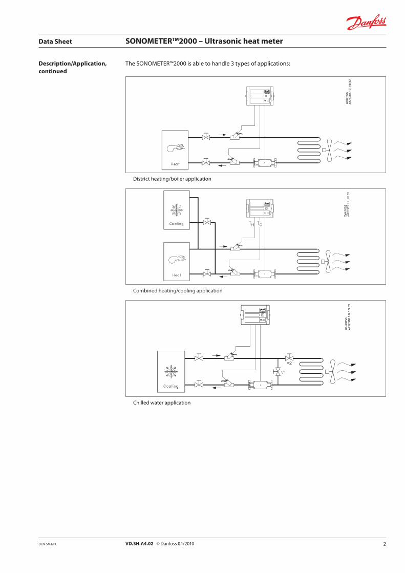
Description/Application, The SONOMETER™2000 is able to handle 3 types of applications:continued
District heating/boiler application
Combined heating/cooling application
Chilled water application
2VD.SH.A4.02 © Danfoss 04/2010DEN-SMT/PL

Data Sheet SONOMETERTM2000 – Ultrasonic heat meter
Ordering AAA BB - C D E F G H - I J K L M - NN O
O - verification0 without approval mark1 compliant according to national regulations3 compliant to MID. No letter of conformity
4 compliant to MID. With letter of conformity (inital verification)
5compliant to MID. With letter of conformity (initial verification) and additional test reports
GH - interface modulesmodules slot 1not relevant / no module in slot 1 0M-Bus module ARS-232 module BReal Data radio module CModule for 2 additional pulse inputs DRS232 adapter for radio Emodules slot 2not relevant / no module in slot 2 0Module for volume and energy pulse outputs KModule for 2 additional pulse inputs LModule for 2 pulse inputs + 1 pulse output M(standard setting for pulse input modules: 100 l / pulsestandard setting for pulse output modules: energy and volume, pulse value is the last digit in the display)
J - temperature sensors (pair)N Pt 500 / ø 5.2 mm / 2 m cable, MIDO Pt 500 / ø 5.2 mm / 3 m cable, MIDP Pt 500 / ø 5.2 mm / 5 m cable, MIDQ Pt 500 / ø 5.2 mm / 10 m cable, MIDT Pt 500 / ø 6.0 mm / 2 m cable, MIDU Pt 500 / ø 6.0 mm / 3 m cable, MIDV Pt 500 / f 6.0mm / 5m cable, MIDW Pt 500 / f 6.0mm / 10m cable, MID
L - accessories / pocket0 without
for ø 5.2 mm temperature sensors (pair1)F brass-pockets, 35 mm, MID 3 DN 15-32G brass-pockets, 52 mm, MID DN 40-65H brass-pockets, 85 mm, MID DN 80-125I brass-pockets, 120 mm, MID DN 150-200
for ø 6.0 mm temperature sensors (pair)V brass-pockets, 40 mm MID DN 25-65W brass-pockets, 85 mm MID DN 80-125X brass-pockets, 120 mm MID DN 150-200Y stainless steel-pockets, 85 mm MID DN 80-125Z stainless steel-pockets, 120 mm MID DN 150-2001 stainless steel-pockets, 155 mm MID DN 200-2502 stainless steel-pockets, 210 mm MID DN 300
AccessoriesR ball valve DN 15 - ½” for direct sensor 2 (1 piece)S ball valve DN 20 - ¾” for direct sensor 2 (1 piece)T ball valve DN 25 - 1” for direct sensor 2 (1 piece)U adapter for mounting direct sensor R½” M 10x1 2
M - connections (sets)0 without1 screwing set R ½” x G ¾ B2 screwing set R ¾” x G 1 B3 screwing set R 1” x G 11/4 B4 screwing set R 1½” x G 2 B
C - pressurenot relevant 0PN 16 CPN 251 D1 Flange versions must be PN 25
NN - country code00 Neutral code with docs in EnglishAT AustriaBA BosniaBG BulgariaCN ChinaDK DenmarkEE EstoniaHR CroatiaCZ Czech RepublicDE GermanyGB United KingdomIE IrelandIT ItalyKZ KazakhstanLV LatviaLT Lithuania
MD MoldovaMK MacedoniaPL PolandRO RomaniaRU RussiaCS SerbiaSK Slovak RepublicSI SloveniaTR TurkeyUA UkraineXM Montenegro
1 versions with one sensor pocket on request2 not possible for ø 6.0 mm sensors3 max temperature: 105°C
1 only for ø 5.2 mm sensors
- - -AAA - applicationaccessories only1 000only temperature sensors1 4TSheat meter for heating 2HEheat meter for cooling 2COheat meter for heating / cooling 2HConly flow sensor for heating 15Honly flow sensor for cooling 15C1 prices valid in the Accessories list
F - power supplynot relevant / with external power supply 1 0battery 3.6 V DC (D-cell) 2 2battery 3.6 V DC (D-cell) 2 with power regulator 51 only for flow sensor2 for internal radio module
BB - (for) flow sensor (type SONO 1500 CT)not relevant / no flow sensor 00qp 0.6 m³/h / 110 mm thread / DN 15 / G¾B / 1 litre / pulse 1Aqp 0.6 m³/h / 130 mm thread / DN 20 / G1B / 1 litre / pulse 1Bqp 0.6 m³/h / 190 mm thread / DN 20 / G1B / 1 litre / pulse 1Cqp 1.0 m³/h / 110 mm thread / DN 15 / G¾B / 1 litre / pulse 1Dqp 1.0 m³/h / 130 mm thread / DN 20 / G1B / 1 litre / pulse 1Eqp 1.0 m³/h / 190 mm thread / DN 20 / G1B / 1 litre / pulse 1Fqp 1.5 m³/h / 110 mm thread / DN 15 / G¾B / 1 litre / pulse 1Gqp 1.5 m³/h / 130 mm thread / DN 20 / G1B / 1 litre / pulse 1Hqp 1.5 m³/h / 190 mm thread / DN 20 / G1B / 1 litre / pulse 1Iqp 2.5 m³/h / 130 mm thread / DN 20 / G1B / 1 litre / pulse 1Jqp 2.5 m³/h / 190 mm thread / DN 20 / G1B / 1 litre / pulse 1Kqp 3.5 m³/h / 260 mm thread / DN 25 / G11/4B / 10 litre / pulse 1Lqp 6 m³/h / 260 mm thread / DN 25 / G11/4B / 10 litre / pulse 1Mqp 10 m³/h / 300 mm thread / DN 40 / G2B 1Nqp 0.6 m³/h / 190 mm flange DN 20 / 1 litre / pulse1 2Aqp 1.0 m³/h / 190 mm flange DN 20 / 1 litre / pulse1 2Bqp 1.5 m³/h / 190 mm flange DN 20 / 1 litre / pulse1 2Cqp 2.5 m³/h / 190 mm flange DN 20 / 1 litre / pulse1 2Dqp 3.5 m³/h / 260 mm flange DN 25 / 10 litre / pulse1 2Eqp 3.5 m³/h / 260 mm flange DN 32 / 10 litre / pulse1 2Fqp 6 m³/h / 260 mm flange DN 25 / 10 litre / pulse1 2Gqp 6 m³/h / 260 mm flange DN 32 / 10 litre / pulse1 2Hqp 10 m³/h / 300 mm flange / DN 401 2Iqp 15 m³/h / 270 mm flange / DN 501 2Jqp 25 m³/h / 300 mm flange / DN 651 2Kqp 40 m³/h / 300 mm flange / DN 801 2Lqp 60 m³/h / 360 mm flange / DN 1001 2M1 only PN 25 possible
D - flow sensor cablenot relevant 02.5 m (standard) A5 m B10 m C
E - installationnot relevant 0forward Freturn R
I - energy units0 not relevant / only flow sensorA kWh (without digit after comma) only for 0.6 - 6 m³/hB MWh (with 1 digit after comma)C MWh (with 2 digits after comma)D MWh (with 3 digits after comma) only for 0.6 - 6 m³/hE GJ (with 1 digit after comma)F GJ (with 2 digits after comma)G GJ (with 3 digits after comma) only for 0.6 - 6 m³/hH Gcal (with 1 digit after comma)I Gcal (with 2 digits after comma)J Gcal (with 3 digits after comma) only for 0.6 - 6 m³/hK MBtu (with 1 digit after comma)L MBtu (with 2 digits after comma)M MBtu (with 3 digits after comma) only for 0.6 - 6 m³/h
K - temperature sensor mounting0 not relevant
1qp 0.6 - 2.5: Prep. for mounting one sensor in flow sensor 1
qp 3.5 - 60 : indirect mounting (2 free sensors)2 qp 3.5 - 25 : Prep. for mounting one sensor in flow sensor 1
3 DEN-SMT/PLVD.SH.A4.02 © Danfoss 04/2010
Data Sheet SONOMETERTM2000 – Ultrasonic heat meter
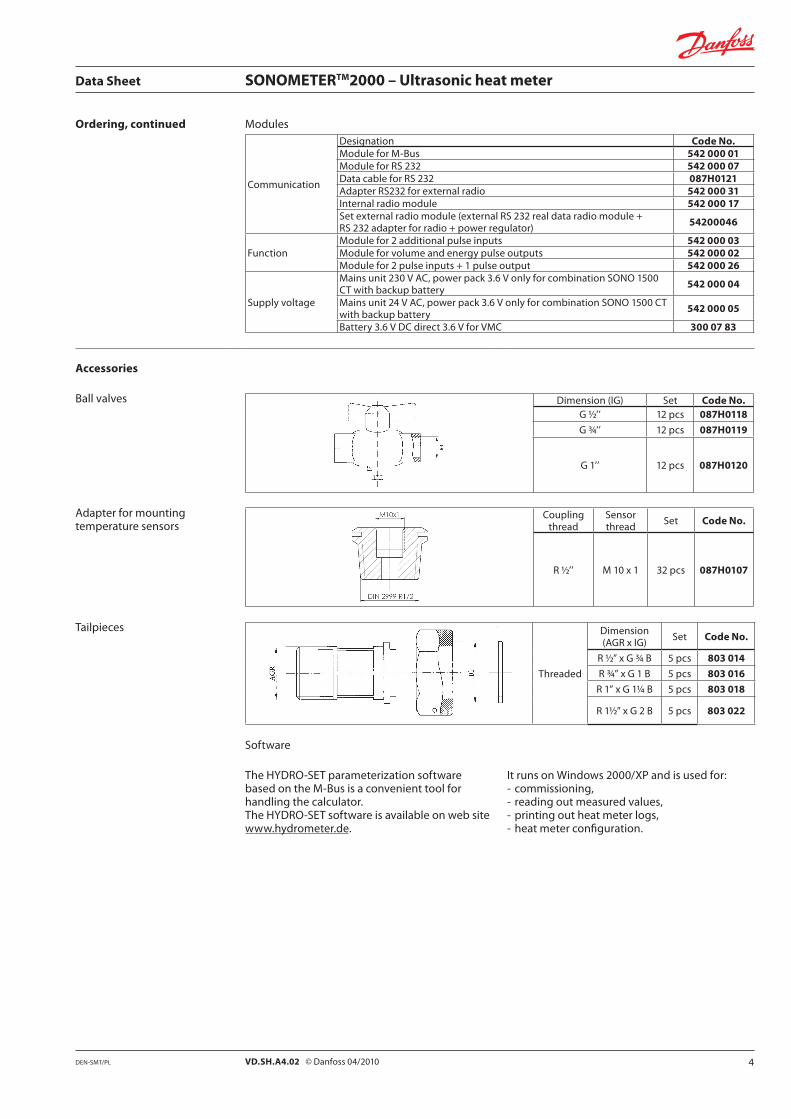
Ordering, continued Modules
Communication
Designation Code No.Module for M-Bus 542 000 01Module for RS 232 542 000 07Data cable for RS 232 087H0121Adapter RS232 for external radio 542 000 31Internal radio module 542 000 17Set external radio module (external RS 232 real data radio module + RS 232 adapter for radio + power regulator) 54200046
FunctionModule for 2 additional pulse inputs 542 000 03Module for volume and energy pulse outputs 542 000 02Module for 2 pulse inputs + 1 pulse output 542 000 26
Supply voltage
Mains unit 230 V AC, power pack 3.6 V only for combination SONO 1500 CT with backup battery 542 000 04
Mains unit 24 V AC, power pack 3.6 V only for combination SONO 1500 CT with backup battery 542 000 05
Battery 3.6 V DC direct 3.6 V for VMC 300 07 83
Accessories
Ball valves Dimension (IG) Set Code No.G ½’’ 12 pcs 087H0118
G ¾’’ 12 pcs 087H0119
G 1’’ 12 pcs 087H0120
Adapter for mounting temperature sensors
Coupling thread
Sensor thread Set Code No.
R ½’’ M 10 x 1 32 pcs 087H0107
Tailpieces
Threaded
Dimension (AGR x IG) Set Code No.
R ½” x G ¾ B 5 pcs 803 014
R ¾” x G 1 B 5 pcs 803 016
R 1” x G 11/4 B 5 pcs 803 018
R 1½” x G 2 B 5 pcs 803 022
Software
The HYDRO-SET parameterization software based on the M-Bus is a convenient tool for handling the calculator.The HYDRO-SET software is available on web site www.hydrometer.de.
It runs on Windows 2000/XP and is used for:- commissioning,- reading out measured values,- printing out heat meter logs,- heat meter configuration.
4DEN-SMT/PL VD.SH.A4.02 © Danfoss 04/2010
Data Sheet SONOMETERTM2000 – Ultrasonic heat meter
Technical dataINFOCAL 6
Basic dataEnviro. class EN 1434 class C / AProtect. class IP 54
Display indication
Display LCD, 7 digitUnits MWh - kWh - GJ - Gcal - MBtu Total values 9 999 999 - 999 999.9 - 99 999.99 - 9 999.999Values displayed Power - energy - flow rate - temperature
TemperatureAmbient
°C0 - 55
Storage -25 - +70
Input
Temp. sensors Type Pt 100 / Pt 500 with 2-wire leads< 10 m
Sensor current mA Pt 100 peak < 8; rms < 0.015Pt 500 peak < 2; rms < 0.012
Measuring cycle T s Mains unit supply: 2Battery: 16
Max. temp. difference ∆θmax
K 177Min. temp. difference ∆θ
min K 3
Starting temp. difference ∆θ K 0.1Absolute temp. measuring range θ °C -9.9...189.9
Supply voltage Operating voltage UN V DC 3.0 / 3.6 (Lithium battery)
SONO 1500 CT
Flow rate
Nominal qp m3/h 0.6 1.0 / 1.5 2.5 3.5 6Maximum q
s m3/h 1.2 2 / 3 5 7 12
Minimum qi l/h 6 10 / 6 10 35 24
Starting l/h 1 2.5 4 7 7Diameter Nominal DN mm 15 20 15 20 20 25 32 25 32Operating pressure Maximum PN bar 16 / 25 25 16 / 25 25 16 / 25 25 16 / 25 25 16 / 25 25
Temperature range Flow sensor °C 5 ... 130 5 ... 150
Medium circulation water (pH: 7 - 10)Pressure loss At q
pΔp mbar 85 36 / 75 100 44 128
Overall length mm 110 130 190 110 130 190 130 190 260 260
Pulse valueVolume l/imp. 0.001...5000 (depend on q
p)
Test1) ml/imp. 5 10 20 20 50Supply voltage Operating U
N
battery supply: 3.0 V DCexternal supply: 3.0..5.5 V DC2)
Basic dataEnviro. class EN 1434 class C / A Protect. class IP 54 (heating) / IP 68 (cooling)
Applicable for direct mounting temp. sensor, Pt 100 / 500 yes no
1) The test impulse depends on digits places of indicator volumes.2) For medium temperatures above 90 °C, the flow sensor must be equipped with an external supply.
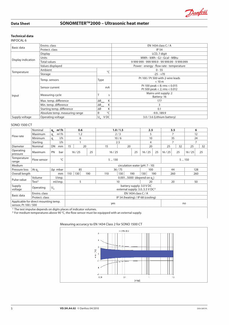
Measuring accuracy to EN 1434 Class 2 for SONO 1500 CT
5 DEN-SMT/PLVD.SH.A4.02 © Danfoss 04/2010
Data Sheet SONOMETERTM2000 – Ultrasonic heat meter
Technical data, continuedSONO 1500 / CT
Flow rate
Nominal qp m3/h 10 15 25 40 60Maximum q
s m3/h 20 30 50 80 120
Minimum1) qi l/h 40 3)/100 60 3)/150 250 160 3)/400 240 3)/600
Starting l/h 15 40 50 80 120Diameter Nominal DN mm 40 50 65 80 100Operating pressure Maximum PN bar 25Temperature range Flow sensor °C 5 - 150Medium circulation water (pH - value: 7 -10)Pressure loss2) At q
p∆p mbar 95 80 75 80 75
Overall length mm 300 270 300 300 360
Pulse valueVolume l/imp. 0.001...5000 (depend on q
p)
Test1) ml/imp 100 150 250 250 500
Supply voltage UN
battery supply: 3.0 V DCexternal supply: 3.0..5.5 V DC4)
Basic dataEnvironmental class EN 1434 class C / AProtection class IP 54 (heating) / IP 68 (cooling)
Apllicable for direct mounting temp. sensor, Pt 100 / 500 no
1) The accuracy is better than 3%2) Acc. to EN 1434 6.173) Only for horizontal installation4) For medium temperatures above 90 °C, the flow sensor must be equipped with an external supply.
Temperature sensors (pair)
Type Direct mounted(EN 1434)
Pocket sensor(EN 1434)
Element Pt 500, 2-wire (EN 60751) Pt 500, 2-wire (EN 60751)Pairing °C 10, 80, 130Medium temperature °C 0...180 0...150Medium District heating water
Response time t 0.5 Typically 0.8 s / 0.4 m/s acc. to sensor pocket technical data table
Pressure rating PN bar 16 acc. to sensor pocket technical data table
Protection class IP 67 IP 65Pipe material W 2.4816 W 1.4303
Temperature sensor pockets
Type Brass Stainless steelMedium temperature °C 0...180Medium District heating water
Response time t 0.5 Typically 9 s / 0.4 m/sTypically 5 s / 0.4 m/s with pasta
Typically 13 s / 0.4 m/sTypically 5 s / 0.4 m/s with pasta
Pressure rating PN bar 25Material CuZn40Pb2 (Ms 58) W 1.4571Adapter CuZn40Pb2 (Ms 58)
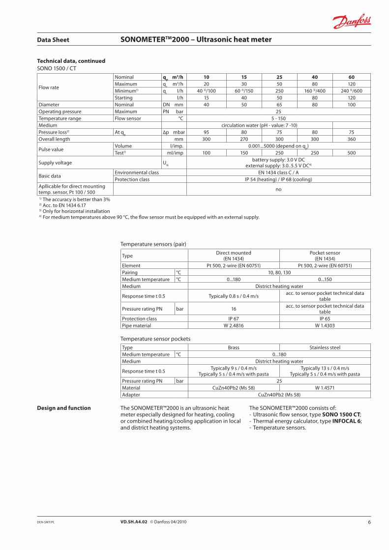
Design and function The SONOMETER™2000 is an ultrasonic heat meter especially designed for heating, cooling or combined heating/cooling application in local and district heating systems.
The SONOMETER™2000 consists of:- Ultrasonic flow sensor, type SONO 1500 CT;- Thermal energy calculator, type INFOCAL 6;- Temperature sensors.
6DEN-SMT/PL VD.SH.A4.02 © Danfoss 04/2010

Data Sheet SONOMETERTM2000 – Ultrasonic heat meter
INFOCAL 6 CalculatorThe calculator contains all the necessary circuits for recording the flow rate and temperature as well as for calculating, logging and displaying the data. The calculator housing can be mounted directly on the flow sensor or on the wall. At application with medium temperature above 90 °C or at temperatures T
water < T
environment the
calculator has to be removed from the flow sensor. The calculator can be conveniently read from a single line 7-digit display with units and symbols. A push-button provides user-friendly control of the various display loops. All failures and faults are recorded automatically and shown on the LC display. To protect the reading data, all the relevant data are saved in a non-volatile memory (EEPROM). This memory saves the measured values, device parameters and types of error at regular intervals.
Temperature SensorsPairs of Pt 100 or Pt 500 temperature sensors with 2-wire leads are used.
InterfacesINFOCAL 6 is equipped as a standard with a ZVEI optical interface with the M-Bus protocol acc. to EN 1434.
This interface is used, for example, for communication with the HYDRO-SET parameterization software. The calculator features 2 slots for the modules. One slot for the function modules, and one for the communication modules.
The following communication modules are available as options:- RS232 module;- M-Bus module acc. to EN 1434;- Real Data Radio Module.
The RS 232 communication module is a serial interface and permits data exchange with the calculator. For this purpose a special data cable is necessary.
The M-Bus module is a serial interface for communication with external devices (M-Bus Repeater) e.g. HYDRO-CENTER. A number of calculators can be connected to a control centre.
The Radio module is an interface for communicate unidirectional over radio predefined data records. The protocol is send every 8 … 19 s. For receiving there are different Hydrometer receiver available. The transmission protocol is editable by HYDRO-SET. If battery supplied the life time is up to 8 years.
-
7 DEN-SMT/PLVD.SH.A4.02 © Danfoss 04/2010
Data Sheet SONOMETERTM2000 – Ultrasonic heat meter
Design and function, continued
Pulse InputTwo pulse inputs are available. The pulse value and the unit is configurable for heat, water, gas or electrical energy meter by HYDRO-SET. The input frequency range is 0 – 8 Hz with pulse-length ≥ 10 ms. Data are separate cumulated in different registers and are also stored on the two accounting day’s. The cable length to pulse input have to be less than 10 m.
Combined pulse input / outputTwo pulse inputs combined with one pulse output are available on one module. The pulse inputs are configurable with value and the unit by HYDRO-SET. The input frequency range is 0 – 8 Hz with pulse-length ≥ 10 ms. The pulse output is also programmable using the HYDRO-SET software. The “open collector” output is supplied with external power of 3-30 VDC and has an output frequency of ≤ 4 Hz. The pulse width of the not potential separated pulses is 100-150 ms.
Pulse outputThe calculator provides levels for two optional external pulse outputs, which can be freely programmed using the HYDRO-SET software. The outputs are “open collector” with external power supply of 3 - 30 V DC and an output frequency of ≤ 4 Hz. The pulse width of the potential separated pulses is 100 - 150 ms.
Possible pulse output values- Energy (standard setting);- Volume (standard setting);- Tariff energy 1;- Tariff energy 2;- Tariff condition 1, limit switch;- Tariff condition 2, limit switch;- Energy error;- Volume error;- Volume with specific resolution (0.1 / 1.0 / 10 /
100 l) at 3 digit after volume comma;- Energy with specific resolution (0.1 kWh) at 3
digit after volume comma;- Leakage detection (2 channel).
Module combinationsThe calculator has a group of extension modules for communication and another group of extension modules for additional functionality. These modules are available first selected within the calculator, or for retrofitting in the field. One single function module as well as one single communication module out of following modules is selectable.
Function modules:- Pulse input module, 2 inputs;- Pulse output module, 2 outputs;- Combined pulse module 2 inputs, 1 output.
Communication modules:- M-Bus or- RS 232 or- Real Data Radio
Event memoryEvents such as changes and faults are stored in a non-volatile memory with a capacity of up to 31 entries. The following events are recorded:- Checksum error;- Temperature measurement error;- Start and end of test mode.
Monthly memoryINFOCAL 6 has a history memory of 24 months. The following values are stored in the EEPROM on the programmed date 1 … 31 via (HYDRO-SET) of the actual month:- Date / Time;- Energy;- Tariff energy 1;- Tariff energy 2;- Tariff definition 1;- Tariff definition 2;- Pulse input 1;- Operation hours;- Volume;- Error day counter;- Maximum monthly flow rate;- Maximum monthly power;- Date of maximum monthly flow rate;- Date of maximum monthly power;- Pulse input 2.
Log memoryThe log memory is used to store consumption values. The storage frequency can be selected from various storage intervals (5. 6, 10, 12, 15, 20, 30, 60 minutes or the default setting of 24 hours, see following table). The data which are stored in Log Memory could be read out with HYDRO-SET and can be used for evaluations.
Extract of possible log memory settings
Storage interval Values
Number of data records
Recording period
5 min. Error status, overload time temperature, overload time flow rate, supply temperature, return temperature, date and time, energy, tariff energy 1, tariff energy 2, tariff definition 1, tariff definition 2, volume, error day counter
440 36.6 h
15 min. 440 110 h
1 h 440 18.3 days
24 h 440 440 days
Accounting dateThe calculator includes two independent memories in which the accumulated energy at two programmable dates is stored.- Last Accounting Date;- Last but one Accounting Date;- Values stored: - Energy; - Volume; - Tariff counter 1; - Tariff counter 2; - Pulse counter 1; - Pulse counter 2; - Date.
8DEN-SMT/PL VD.SH.A4.02 © Danfoss 04/2010

Data Sheet SONOMETERTM2000 – Ultrasonic heat meter
Design and function, continued
Max. ValuesThe calculator creates max. values for power and flow rate based on consumption time, which are stored in the EEPROM. The integration intervals are adjustable to 6, 15, 30 or 60 minutes and 24 h. Default setting is 60 minutes.
Tariff FunctionThe calculator offers two optional tariff memories for monitoring plant load states for limit tariffs. Here it concerns threshold value tariffs. Extensive tariff conditions make it possible to adapt the calculator individually to the required customer-specific applications.
Both tariffs are separately configurable and independent from each other. Energy or time can be measured alternatively per tariff register dependent on the tariff mode adjusted in each case.
With the “time triggered tariff function” (type Z) the switch-on time and the switch-off time are adjustable independent from each other for each day of the week in steps of 15 minutes.
The following limit types are possible:(This example applies to the display at 3 digit after volume comma)
Leakage Function - on request
Type Description LIMIT LIMIT resolution
ΔT Temperature difference 1 ... 190 °C 1 °C
-ΔT Negative temperature difference 1 ... 190 °C 1 °C
TR
Return temperature (low) 1 ... 190 °C 1 °C
TV
Supply temperature (high) 1 ... 190 °C 1 °C
P Power 1 ... 255 kW 1 kW
Q Flow 100 ... 25 500 l/h 100 l/h
FE “Theoretically Supply Energy” with return temperature of 0 °C - -
Z “Time triggered” counting energy - -
E “External” counting energy - -
Display ControlThe readings are displayed on the calculator by a 7-digit LCD with units and symbols.
Loop StructureThe INFOCAL 6 display has six loops. Some display windows consist of two (to maximum seven) displays that are shown alternately at 4-second intervals. Some pictures in loops or a complete loop can be deactivated separately.
For quick visual guidance, the loops in the display are numbered from 1 to 6.
The main loop with the current data, e.g. for energy, volume and flow rate, is programmed as default setting.In the standard setting the loop no. 5 (tariff loop) is not activated.
9 DEN-SMT/PLVD.SH.A4.02 © Danfoss 04/2010

Data Sheet SONOMETERTM2000 – Ultrasonic heat meter
Overview of Loops
10DEN-SMT/PL VD.SH.A4.02 © Danfoss 04/2010

Data Sheet SONOMETERTM2000 – Ultrasonic heat meter
Informative Displays (Standard)
Loop Sequence Window 1 Window 2 Window 3 Window 4
“1”Main loop
1.1 Accumulated Energy
1.2 Volume
1.3 Flow
1.4 Power
1.5 Supply temperature Return temperature
1.6 Difference temperature
1.7 Operating hours
1.8 [off] Monthly peak power Date
1.9 Error code
1.10 Display test
1.11 [off] Tariff energy 1
1.12 [off] Tariff energy 2
1.13 [off] Pulse input ‘In 1’ Pulse input counter 1
1.14[off] Pulse input ‘In 2’ Pulse input counter 2
1.15 Leakage detection error Leakage detection heating
1.16 Accounting date last time Accounting date last time Accounting value Energylast time
Accounting value Volumelast time
1.17 Accounting date next tolast time
Accounting date next tolast time
Accounting value Energynext to last time
Accounting value Volumenext to last time
1.18 Secondary address Secondary M-Bus address
1.19 Actual maximal flow Date actual maximal flow
Loop Sequence Window 1 Window 2 Window 3 Window 4 Window 5 Window 6 Window 7 Window 8 Window 9 Window 10
“1”Main loop 1.20 LOG Date of
last month Energy Tariff energy 1
Tariff energy 2 Volume Max. flow Max.
powerImpulse
counter 1Impulse
counter 2
Loop Sequence Window 1 Window 2 Window 3 [off] Window 4
“2”Accountingdate loop
2.1 Accounting date 1 Accounting date 1 energy Accounting date 1 volume ‚Accd 1’
2.2 Accounting date 1previous year
Accounting date 1previous year energy
Accounting date 1previous year volume ‚Accd 1’
2.3 Accounting date ‚Accd 1’ Accounting date 1 in the future
2.4 Accounting date 2 Accounting date 2 energy Accounting date 2 volume ‚Accd 2’
2.5 Accounting date 2 previous year
Accounting date 2 previous year energy
Accounting date 2 previous year volume ‚Accd 2’
2.6 Accounting date ‚Accd 2’ Accounting date 2 in the future
Loop Sequence Window 1 Window 2
„3“Info loop
3.1 Current date
3.2 ‚SEC_Adr’ Secondary address M-Bus
3.3 ‚Pri_Adr’ Primary address M-Bus
3.4 ‚ Pt 100 r’ or ‚ Pt 500 r’ showsinstallation “forward or return”
3.5 Monthly peak flow rate Date max. flow rate
3.6 Monthly peak power Date max. power
3.7 Integration interval (maximum value)
3.8 Number of error day’s
3.9 Pulse output ‚Out 1’ Pulse value and unit pulse output 1
3.10 Pulse output ‚Out 2’ Pulse value and unit pulse output 2
3.11 Pulse output ‚Out 3’ Pulse value interface pulse
3.12 Software version
[off] = not active
11 DEN-SMT/PLVD.SH.A4.02 © Danfoss 04/2010

Data Sheet SONOMETERTM2000 – Ultrasonic heat meter
Loop Sequence Window 1 Window 2 Window 3
“4”Pulse input
loop
4.1 Pulse input ‚In1’ Pulse input counter 1 Pulse value 1
4.2 Pulse input ‚In2’ Pulse input counter 2 Pulse value 2
4.3 [off] Accounting date 1 Pulse input ‚In1’ Acc.date 1 Pulse value 1
4.4 [off] Accounting date 1 Pulse input ‚In2’ Acc.date 1 Pulse value 2
4.5 [off] Accounting date 1 previous year Pulse input ‚In1’ Acc.date 1 previous year
Pulse value 1
4.6 [off] Accounting date 1 previous year Pulse input ‚In2’ Acc.date 1 previous year
Pulse value 2
4.7 [off] Accounting date 2 Pulse input ‚In1’ Acc.date 2 Pulse value 1
4.8 [off] Accounting date 2 Pulse input ‚In2’ Acc.date 2 Pulse value 2
4.9 [off] Accounting date 2previous year Pulse input ‚In1’ Acc.date 2 previous year
Pulse value 1
4.10 [off] Accounting date 2 previous year Pulse input ‚In2’ Acc.date 2 previous year
Pulse value 2
Loop Sequence Window 1 Window 2 Window 3
“5”Tariff loop
5.1 [off] Tariff energy 1 Tariff function 1 (e.g. ‚t 01’) Limit tariff 1
5.2 [off] Tariff energy 2 Tariff function 2 (e.g. ‚t 02’) Limit tariff 2
5.3 [off] Accounting date 1 Accounting date 1 tariff energy 1 ‚Accd 1’
5.4 [off] Accounting date 1 Accounting date 1 tariff energy 2 ‚Accd 1’
5.5 [off] Accounting date 1previous year Accounting date 1 tariff energy 1 ‚Accd 1’
5.6 [off] Accounting date 1previous year Accounting date 1 tariff energy 2 ‚Accd 1’
5.7 [off] Accounting date 2tariff energy 1 Accounting date 2 tariff energy 1 ‚Accd 2’
5.8 [off] Accounting date 2 Accounting date 2 tariff energy 2 ‚Accd 2’
5.9 [off] Accounting date 2 previous year Accounting date 2 tariff energy 2 ‚Accd 2’
5.10 [off] Accounting date 2 previous year Accounting date 2 tariff energy 2 ‚Accd 2’
Loop Sequence Window 1 Window 2 Window 3 [off] Window 4 [off] Window 5 Window 6 Window 7
“6”Monthly
valueloop
6.1 Last month Energy Tariff energy 1 Tariff energy 2 Volume Max. flow rate Max. power
6.2 Month –1 Energy Tariff energy 1 Tariff energy 2 Volume Max. flow rate Max. power
6.3 Month -2 Energy Tariff energy 1 Tariff energy 2 Volume Max. flow rate Max. power
...
6.24 Month -23 Energy Tariff energy 1 Tariff energy 2 Volume Max. flow rate Max. power
[off] = not active
Simple operationA push-button mounted on the front of the calculator is used to switch to the various displays. The button can be pressed for a short or long time. A short press of the button ( < 3 seconds) switches to the next display within a loop and a long press ( > 3 seconds) switches to the next display loop. The “Energy” window (sequence 1.1) in the main loop is the basic display.
The calculator switches automatically to power save mode if the button is not pressed for approx. 4 minutes and returns to the basic display when the button is pressed again. The loop settings can be programmed to suit the customer’s individual requirements using the HYDRO-SET software.
12DEN-SMT/PL VD.SH.A4.02 © Danfoss 04/2010
Data Sheet SONOMETERTM2000 – Ultrasonic heat meter
SONO 1500 CT Power supplyThe standard version contains a 3.0 VDC lithium battery (max. 90 °C) with a lifetime of 12 years (depends on configuration). It’s also possible to use an external supply e.g. from a calculator.
Characteristic for ext. power supply:- Power supply 3.0 ... 5.5 V DC;- Power consumption < 130 mAh per year;- Impulse current < 10 mA.
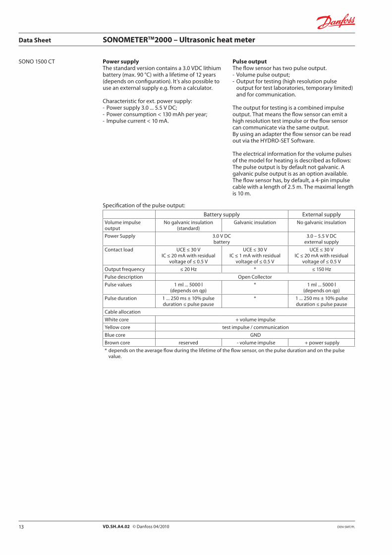
Pulse outputThe flow sensor has two pulse output.- Volume pulse output;- Output for testing (high resolution pulse
output for test laboratories, temporary limited) and for communication.
The output for testing is a combined impulse output. That means the flow sensor can emit a high resolution test impulse or the flow sensor can communicate via the same output.By using an adapter the flow sensor can be read out via the HYDRO-SET Software.
The electrical information for the volume pulses of the model for heating is described as follows: The pulse output is by default not galvanic. A galvanic pulse output is as an option available. The flow sensor has, by default, a 4-pin impulse cable with a length of 2.5 m. The maximal length is 10 m.
Specification of the pulse output:
Battery supply External supplyVolume impulseoutput
No galvanic insulation (standard)
Galvanic insulation No galvanic insulation
Power Supply 3.0 V DCbattery
3.0 – 5.5 V DCexternal supply
Contact load UCE ≤ 30 VIC ≤ 20 mA with residual
voltage of ≤ 0.5 V
UCE ≤ 30 VIC ≤ 1 mA with residual
voltage of ≤ 0.5 V
UCE ≤ 30 VIC ≤ 20 mA with residual
voltage of ≤ 0.5 V
Output frequency ≤ 20 Hz * ≤ 150 Hz
Pulse description Open Collector
Pulse values 1 ml ... 5000 l(depends on qp)
* 1 ml ... 5000 l(depends on qp)
Pulse duration 1 ... 250 ms ± 10% pulseduration ≤ pulse pause
* 1 ... 250 ms ± 10% pulseduration ≤ pulse pause
Cable allocation
White core + volume impulse
Yellow core test impulse / communication
Blue core GND
Brown core reserved - volume impulse + power supply
* depends on the average flow during the lifetime of the flow sensor, on the pulse duration and on the pulse value.
13 DEN-SMT/PLVD.SH.A4.02 © Danfoss 04/2010
Data Sheet SONOMETERTM2000 – Ultrasonic heat meter
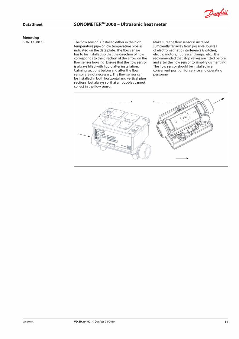
MountingSONO 1500 CT The flow sensor is installed either in the high
temperature pipe or low temperature pipe as indicated on the data plate. The flow sensor has to be installed so that the direction of flow corresponds to the direction of the arrow on the flow sensor housing. Ensure that the flow sensor is always filled with liquid after installation. Calming sections before and after the flow sensor are not necessary. The flow sensor can be installed in both horizontal and vertical pipe sections, but always so, that air bubbles cannot collect in the flow sensor.
Make sure the flow sensor is installed sufficiently far away from possible sources of electromagnetic interference (switches, electric motors, fluorescent lamps, etc.). It is recommended that stop valves are fitted before and after the flow sensor to simplify dismantling. The flow sensor should be installed in a convenient position for service and operating personnel.
14DEN-SMT/PL VD.SH.A4.02 © Danfoss 04/2010

Data Sheet SONOMETERTM2000 – Ultrasonic heat meter
DimensionsSONO 1500 CT
Nominal size qp
= 0.6 m³/h qp
= 1.0 / 1.5 m³/h qp
= 2.5 m³/h qp
= 3.5 m³/h qp
= 6.0 m³/h
L [mm] 110 130 190 190 110 130 190 190 130 190 190 260 260 260 260 260 260
L1 [mm] 190 230 190 230 230 380 - - 380 - -
L2 [mm] 90
B [mm] 65.5
H [mm] 54.5 56.5 56.5 56.5 54.5 56.5 56.5 56.5 56.5 56.5 56.5 61 61 61 61 61 61
h [mm] 14.5 18 18 47.5 14.5 18 18 47.5 18 18 47.5 23 50 62.5 23 50 62.5
AGZ G¾B DN 15
G1B DN 20
G1B DN 20
FL DN 20
G¾B DN 15
G1B DN 20
G1B DN 20
FL DN 20
G1B DN 20
G1B DN 20
FL DN 20
G11/4B DN 25
FL DN 25
FL DN 32
G11/4B DN25
FL DN 25
FL DN 32
AGV R½ R¾ R¾ - R½ R¾ R¾ - R¾ R¾ - R1 - - R1 - -
D [mm] - - - 105 - - - 105 - - 105 - 114 139 - 114 139
d [mm] - - - 14 - - - 14 - - 14 - 14 18 - 14 18
F [mm] - - - 95 - - - 95 - - 95 - 100 125 - 100 125
K [mm] - - - 75 - - - 75 - - 75 - 85 100 - 85 100
Weight [kg] 0.6 0.61 0.63 2.7 0.6 0.61 0.63 2.7 0.61 0.63 2.7 1.35 3.35 4.65 1.35 3.35 4.65
FL - flanged connection
15DEN-SMT/PL VD.SH.A4.02 © Danfoss 04/2010
Data Sheet SONOMETERTM2000 – Ultrasonic heat meter
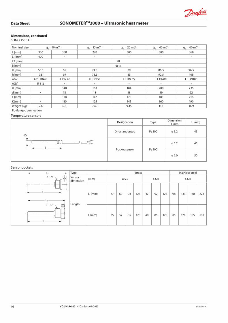
Dimensions, continuedSONO 1500 CT
Nominal size qp
= 10 m³/h qp
= 15 m³/h qp
= 25 m³/h qp
= 40 m³/h qp
= 60 m³/h
L [mm] 300 300 270 300 300 360
L1 [mm] 400 - - - - -
L2 [mm] 90
B [mm] 65.5
H [mm] 66.5 66 71.5 79 86.5 96.5
h [mm] 33 69 73.5 85 92.5 108
AGZ G2B DN40 FL DN 40 FL DN 50 FL DN 65 FL DN80 FL DN100
AGV R 1 ½ - - - - -
D [mm] - 148 163 184 200 235
d [mm] - 18 18 18 19 22
F [mm] - 138 147 170 185 216
K [mm] - 110 125 145 160 190
Weight [kg] 2.6 6.6 7.45 9.45 11.1 16.9
FL- flanged connection
Temperature sensors
Designation Type DimensionD (mm) L (mm)
Direct mounted Pt 500 ø 5.2 45
Pocket sensor Pt 500
ø 5.2 45
ø 6.0 50
Sensor pockets
Type Brass Stainless steel
Sensor dimension (mm) ø 5.2 ø 6.0 ø 6.0
Length
L1 (mm) 47 60 93 128 47 92 128 98 133 168 223
L (mm) 35 52 85 120 40 85 120 85 120 155 210
16 DEN-SMT/PLVD.SH.A4.02 © Danfoss 04/2010

Data Sheet SONOMETERTM2000 – Ultrasonic heat meter
INFOCAL 6
17DEN-SMT/PL VD.SH.A4.02 © Danfoss 04/2010

Data Sheet SONOMETERTM2000 – Ultrasonic heat meter
18 Produced by Danfoss A/S © 04/2010VD.SH.A4.02