Embed Size (px)
Citation preview

RE 15330/2.2019
Replaces: EN777-7
RE15330/2.2019, Bosch Rexroth AB
Data sheet Hägglunds Spider Control System
RE 15330

Hägglunds Spider, Control system 2/263 Preface
RE15330/2.2019, Bosch Rexroth AB
Preface The data specified in this document only serve to describe the product. No statements concerning a certain condition or suitability for a certain application can be derived from our information. The information given does not release the user from the obligation of own judgment and verification. It must be remembered that our products are subject to a natural process of wear and aging. © This document, as well as the data, specifications and other information set forth in it, are the exclusive property of Bosch Rexroth AB. It may not be reproduced or given to third parties without its consent. Changes in the equipment may occur. We therefore reserve the right to introduce amendments in the manual as we deem necessary without notice or obligations.
This data sheet is valid for standard Spider control unit generation 2. For older control units please contact your nearest Bosch Rexroth representative. The cover shows an example configuration. The product supplied may therefore differ from the figure shown. The original operating instructions were prepared in English. Updated information from last version of the manual is marked with red text in this document. Information about specific order related connections and configuration is attached in the system documentation at delivery.
Warning signs In this manual you will find the following signs which indicate a potential hazard, which can or will cause personal injury or substantial property damage. Depending on the probability of the hazard, and how serious the injury or property damage could be, there are three levels of classification.
Warning sign (warning triangle): Draws attention to
the hazard Signal word: Identifies the degree of hazard Type of risk: Specifies the type or source of the
hazard Consequences: Describes the consequences of non-
compliance Precautions: Specifies how the hazard can be
prevented The signal words have the following meaning: Signal word Application
Indicates an imminently hazardous
situation which, if not avoided, will certainly result in death or serious injury.
Indicates a potentially hazardous
situation which, if not avoided, will certainly result in death or serious injury.
Indicates a potentially hazardous
situation which, if not avoided, could result in minor or moderate injury or damage to equipment.

Hägglunds Spider, Control system 3/263 Preface
RE15330/2.2019, Bosch Rexroth AB
Preface .................................................................................................................. 2
Warning signs ........................................................................................................ 2
1 Introduction ......................................................................................................... 5 1.1 Description ........................................................................................................................................................... 5 1.2 Serial number ..................................................................................................................................................... 10 1.3 Card number ...................................................................................................................................................... 11 1.4 Versions and changes ....................................................................................................................................... 12 1.5 Ordering code .................................................................................................................................................... 24
2 Technical data .................................................................................................. 25 2.1 Mechanical ......................................................................................................................................................... 25 2.2 Supply and output voltage ................................................................................................................................. 29 2.3 Inputs ................................................................................................................................................................. 30 2.4 Outputs ............................................................................................................................................................... 31 2.5 Communication .................................................................................................................................................. 31
3 Connection ....................................................................................................... 32 3.1 Wiring ................................................................................................................................................................. 32 3.2 Power supply ...................................................................................................................................................... 32 3.3 Input signals ....................................................................................................................................................... 33 3.4 Output signals .................................................................................................................................................... 48 3.5 Interconnection terminal ..................................................................................................................................... 54 3.6 Communication ports ......................................................................................................................................... 55 3.7 Terminal functions .............................................................................................................................................. 59
4 Indication and setting ........................................................................................ 64 4.1 Display information............................................................................................................................................. 64 4.2 Information on normal drive and alarms ............................................................................................................ 66 4.3 Reset of alarms and warnings ........................................................................................................................... 67 4.4 Front panel buttons ............................................................................................................................................ 68 4.5 Main card jumpers and indications .................................................................................................................... 70 4.6 Power supply ...................................................................................................................................................... 76 4.8 RMS card ........................................................................................................................................................... 93 4.9 LIC Unit .............................................................................................................................................................. 94 4.10 Error codes ....................................................................................................................................................... 95 4.11 Text settings ..................................................................................................................................................... 96
5 Parameters ....................................................................................................... 97 5.1 Parameter tree ................................................................................................................................................... 97 5.2 Configurable Parameters ................................................................................................................................... 98 5.2.1 Main settings ................................................................................................................................................... 98 5.2.2 Pump outputs ................................................................................................................................................ 101 5.2.3 Digital inputs .................................................................................................................................................. 103 5.2.4 Digital outputs ............................................................................................................................................... 107 5.2.5 Pulse inputs ................................................................................................................................................... 114 5.2.6 Analog inputs ................................................................................................................................................ 115 5.2.7 Analog outputs .............................................................................................................................................. 122 5.2.8 Bus ................................................................................................................................................................ 124 5.2.9 Pump monitor ................................................................................................................................................ 130 5.2.10 Tank monitor ............................................................................................................................................... 132 5.2.11 Aux monitor ................................................................................................................................................. 133 5.2.12 Drive monitor ............................................................................................................................................... 137 5.2.13 Hydraulic motor monitor .............................................................................................................................. 140 5.2.14 Drive logic ................................................................................................................................................... 141 5.2.15 Value threshold ........................................................................................................................................... 145 5.2.16 Drive 1 basic ............................................................................................................................................... 147 5.2.17 Drive 2 basic ............................................................................................................................................... 149 5.2.18 Shredder 1 .................................................................................................................................................. 151 5.2.19 Shredder 2 .................................................................................................................................................. 152 5.2.20 Synchro ....................................................................................................................................................... 153 5.2.21 Pressure 1 ................................................................................................................................................... 155 5.2.22 Pressure 2 ................................................................................................................................................... 156 5.2.23 Reading 1 .................................................................................................................................................... 157 5.2.24 Reading 2 .................................................................................................................................................... 158 5.2.25 Spare functions ........................................................................................................................................... 160

Hägglunds Spider, Control system 4/263 Preface
RE15330/2.2019, Bosch Rexroth AB
5.2.26 Drive log ...................................................................................................................................................... 160
6 Settings and function ...................................................................................... 164 6.1 General system setup ...................................................................................................................................... 165 6.3 Ramp ................................................................................................................................................................ 166 6.4 Output .............................................................................................................................................................. 167 6.5 Speed feedback ............................................................................................................................................... 169 6.7 Monitoring ........................................................................................................................................................ 173 6.8 Analog inputs ................................................................................................................................................... 175 6.9 Digital inputs ..................................................................................................................................................... 176 6.10 Digital outputs ................................................................................................................................................ 181 6.11 Signal monitor ................................................................................................................................................ 185 6.12 Shredder ........................................................................................................................................................ 189 6.13 Synchro .......................................................................................................................................................... 190 6.14 Pressure control ............................................................................................................................................. 191 6.15 Bus Communication ....................................................................................................................................... 194 6.16 Drive monitoring log ....................................................................................................................................... 220 6.17 Analog outputs ............................................................................................................................................... 222 6.18 Language selection ........................................................................................................................................ 222 6.19 Brake control .................................................................................................................................................. 223 6.20 Machine stop .................................................................................................................................................. 224 6.21 Program update ............................................................................................................................................. 225 6.22 Hardware calibration ...................................................................................................................................... 225 6.23 Flushing .......................................................................................................................................................... 226 6.24 Hydraulic motor temperature monitoring........................................................................................................ 227 6.25 Pulse inputs .................................................................................................................................................... 227 6.26 Compare registers.......................................................................................................................................... 227 6.27 Cooler control ................................................................................................................................................. 232 6.28 Drive logic ...................................................................................................................................................... 233 6.29 Value threshold .............................................................................................................................................. 234 6.30 Local interface unit ......................................................................................................................................... 235 6.31 S-link .............................................................................................................................................................. 236
7 Block diagrams ............................................................................................... 237 7.1 Digital in/outputs ............................................................................................................................................... 237 7.2 Analog in/outputs ............................................................................................................................................. 240 7.3 Pump outputs ................................................................................................................................................... 243 7.4 Monitor ............................................................................................................................................................. 244 7.5 Basic function ................................................................................................................................................... 250 7.6 Shredder function ............................................................................................................................................. 252 7.7 Synchro function .............................................................................................................................................. 254 7.8 Pressure Function ............................................................................................................................................ 256 7.9 Machine stop .................................................................................................................................................... 257 7.10 Flush control ................................................................................................................................................... 258 7.11 Compare registers.......................................................................................................................................... 259 7.12 Drive logic ...................................................................................................................................................... 260 7.13 Threshold function.......................................................................................................................................... 261
8 Declaration of conformity ................................................................................ 262
Notes ................................................................................................................. 263

Hägglunds Spider, Control system 5/263 1 Introduction
RE15330/2.2019, Bosch Rexroth AB
1 Introduction
1.1 Description The Spider unit is a microcontroller based system, configurable to suit different application needs. It is designed to match the two or three door PEC or DU power unit, also with a one door unit added. The control system can control pumps with double coil or single coil in one direction. The unit can for PEC be mounted inside the power unit, in the power unit door, on the outside of the power unit or delivered separate with wall brackets or panel flange to be wired in by the customer. Cable sets can be supplied as an option.
The unit will for DU be mounted on the power unit side with the control panel (LIU) on the outside or inside of the front door communicating via CAN. The configuration of the pre-programmed system functions is done using the front panel with help from the text displays or via a serial connection from a laptop. The configuration mode can be protected with a password. The Spider unit can control the system with different settings of electric motor/pump configuration.
One to four pumps for one drive:
Two to four pumps for two drives with separate function:
DRIVE
DRIVE
P
EM
P
EM
P
EM
DRIVE P
EM
P
EM EM
P
DRIVE P
P
P
EM EM
P
EM
DRIVE P
P
P
P
EM EM
DRIVE
DRIVE
EM
P P
EM
P
EM
DRIVE
DRIVE P
EM
P
EM
DRIVE

Hägglunds Spider, Control system 6/263 1 Introduction
RE15330/2.2019, Bosch Rexroth AB
M
Two to four pumps for two drives with common function. If one stops by a fault the other will also stop:
The Monitor function can health monitor the power unit switches and give information on the text display about warnings or alarms. An alarm will stop the electric motor or motors if the digital interlock output
is connected via a relay to the starter interlock circuit. Up to 4 pumps can be controlled in parallel for the same drive
DRIVE
DRIVE P
P P
EM EM
DRIVE
DRIVE P
P
EM EM
DRIVE P
EM
DRIVE P
DRIVE
DRIVE
P
P
EM EM
P
P
EM
DRIVE
DRIVE
EM
P
EM
P
P
EM
EM
DRIVE
DRIVE
P
EM
P P
P
EM
DRIVE
DRIVE
P
P
P
EM EM
P
M M
M
M
M

Hägglunds Spider, Control system 7/263 1 Introduction
RE15330/2.2019, Bosch Rexroth AB
The Basic function has added functions for power limitation and closed loop speed feedback via a PID-regulator. Inputs are available for analog or digital speed encoders.
The unit can also monitor analog signals on the display such as speed, E-motor current, pressure etc.
The Shredder function has the same functions as Basic and added functions for reversing by an overload-stopped drive. It is possible to maximise the
number of reversals within a time limit and stop the drive when exceeded. The drive can be set to change direction after an adjustable time interval.
M
M

Hägglunds Spider, Control system 8/263 1 Introduction
RE15330/2.2019, Bosch Rexroth AB
The Friction function has the same functions as Basic and added functions for control of two hydraulic
drives driven together with a ratio between the motors.
The Friction slave function has the same functions as Basic and added functions for control of two hydraulic
drives driven together with a ratio in relation to the master setpoint.
The Synchro function has the same functions as Basic and added functions for position control between two hydraulic drives. It is possible by an
external signal to set the angle between the rolls. Ratio drive is also possible. This mode requires digital speed encoders.
M
M
M
M

Hägglunds Spider, Control system 9/263 1 Introduction
RE15330/2.2019, Bosch Rexroth AB
The pressure control function output is added to the ramped flow command. The function compares actual
pressure to a setpressure and gives a positive or negative output depending on sign of the difference and action direction of regulation.
The Spider unit front has push-buttons for start and stop of the drive, local/remote, speed setpoint by increase and decrease in local mode, inch reverse, regulated/non-regulated drive and auto/manual drive in shredder mode. These push-button functions can be bypassed in the configuration of the system functions. Two types of displays are available, OLED with yellow signs (required for Japanese texts) and VFD with blue signs (required for Chinese texts). All inputs and outputs are configurable and can be connected to pre-programmed functions in the setup of the system. All signals are as standard wired to contact terminals or via fieldbus port (optional). The digital inputs can be configured to functions for eg. start/stop, reverse, reset, monitoring of the power unit, auxiliary monitor where it is possible to set the function and display monitor text.
The digital outputs can be configured to functions for eg. common alarm/warning, ready to use, drive started, shredder blocked, cooler and heater control. The outputs are of dry relay contact type. The analog inputs can be configured to functions for eg. tank temp, speed, pressure, power for monitoring and control. The inputs can be configured for current loop or voltage. The analog outputs can be configured to monitor eg. speed, pressure, temp. The outputs can be configured for current loop or voltage. The system includes a drive monitoring function with drive time counters, alarm/warning list and 8 scalable log channels with data download via serial interface. The system can communicate with ODiN condition monitoring database via external modem for health monitoring of the hydraulic system.
M
M

Hägglunds Spider, Control system 10/263 1 Introduction
RE15330/2.2019, Bosch Rexroth AB
1.2 Serial number
This serial number system is used up to Serial number -4653:
E01P x x x - xxxx
Article group for Spider Serial number
Function: M= Monitor function B = Basic function S = Shredder function Z = Synchro function F = Friction function R = MRC function Serial number after -4653 is Cxxxxx without any correlation to the function. C is standing for Controls but the following number is used for all types of different control equipment.
Drive 1 config: 1= 1 Emotor - 1 Pump 2= 1 Emotor - 2 Pumps 3= 2 Emotors - 2 Pumps 4= 2 Emotors - 3 Pumps 5= 2 Emotors - 4 Pumps 6= 3 Emotors - 3 Pumps 7= 3 Emotors - 4 Pumps 8= 1Emotor - Tandem pump 1 9= 1Emotor - Tandem pump 2
Drive 2 config: 0= No Emotor, No pump 1= 1 Emotor - 1 Pump 2= 1 Emotor - 2 Pumps 3= 2 Emotors - 2 Pumps 4= 2 Emotors - 3 Pumps 5= 2 Emotors - 4 Pumps 6= 3 Emotors - 3 Pumps 7= 3 Emotors - 4 Pumps 8= Emotor common w.drive 1 - Tandem pump1 9= Emotor common w.drive 1 - Tandem pump2

Hägglunds Spider, Control system 11/263 1 Introduction
RE15330/2.2019, Bosch Rexroth AB
1.3 Card number
The individual card number is marked on the card at final test. The number consists of an individual number and year and week for the production test. The hardware revision marking is adjacent to the card number
5371 1135 R3B
Individual number Year and week for production test
Example:
Layout Rev A Layout Rev B
Hardware revision

Hägglunds Spider, Control system 12/263 1 Introduction
RE15330/2.2019, Bosch Rexroth AB
1.4 Versions and changes
1.4.1 Software versions
The software version is shown on the display for drive 1 at power up of the system.
Version 0.2, 1.0-1.3
Test versions during the first time of developement of the system. Version 1.4.0 Ready 96-05-26 First delivered version. Four prototype systems were delivered to customers in Sweden. Function block diagrams Block 1B, Block 2B and Block 3B.
Version 1.4.1
Ready 96-08-23
New version of O´Tool operating system. Bug fixes: -Idle function could cause watchdog problem by stack overflow.
-PWM (Pulse Width Modulation for the output signal to the pump strokers) routine changed. Problems with PWM frequency >1000Hz.
Function block diagrams Block 1B, Block 2B and Block 3B.
Version 2.0.0
Ready 96-08-30
Adapted to the new version of the hardware (rev.A). Bug fixes -PWM routine changed. Problems with PWM frequency <1000Hz caused by software compilator bug. Function block diagrams Block 1C, Block 2C and Block 3C.
Version 2.1.0
Ready 96-11-27
Readings from both drives can be used in any position. Only readings for drive 1 could earlier be used on display 1.
Better protection against uncontrolled reversing of drive with use of analogue encoder for speed feedback.
Better accuracy for reading of speed encoder. New digital inputs: -Local1 -Change between Local and Remote drive 1. -Local2 -Change between Local and Remote drive 2. -Shutdown1 -Open output to pump 1 without open e-motor interlock. -Shutdown2 -Open output to pump 2 without open e-motor interlock. -Shutdown1+2 -Open outputs to pumps without open e-motor interlocks. Function block diagrams Block 1D, Block 2D and Block 3D.
Version 2.2.0
Ready 97-06-27
Slower change of local set point command. Change stops at zero before change of direction.
Reset of ”shredder blocked” with stop button.
Ramp for ratio in synchro mode.
Functions in synchro mode to give priority for the ratio between the rolls independent of the settings of speed and ratio commands.

Hägglunds Spider, Control system 13/263 1 Introduction
RE15330/2.2019, Bosch Rexroth AB
New digital outputs: -Auto1 -Indication man/auto in auto for drive1. -Auto2 -Indication man/auto in auto for drive2. Bug fixes: -Some monitor reading changed selections after power up.
-Interference between speed measuring could occur if two digital encoders were used. -Feedback is disconnected at zero input command with analogue speed encoder to protect against uncontrolled reversing of drive. -Stop reverse always active with digital encoder detection of blocking in shredder mode. -When more than 20 reversals in Shredder mode, reverse counter could start to write in forbidden area.
Function block diagrams Block 1E, Block 2E and Block 3E.
Version 2.3.0
Ready 98-03-09
Functions for swashangle feedback (Hydrokraft) pumps.
Output enable (for PWM output) open if e-motor is not started and by swashangle error.
Parameter for valve resistance changed to feedback gain.
Letter Ä changed to A in HÄGGLUNDS due to text problems during start-up. New digital outputs: -Failsafe 1 -Output for fail safe valve drive 1.
-Failsafe 2 -Output for fail safe valve drive 2. Function block diagrams: Block 1F, Block 2F and Block 3F. Version 2.3.1 Ready 98-04-03 Bug fixes: -Bug in PWM function could destroy register. Function block diagrams: Block 1F, Block 2F and Block 3F.
Version 2.4.0
Ready 98-05-04
Max current settings for both drives and password can be changed with drives started.
Readings of speed can be shown with 2 decimals.
Set point can be indicated in rpm.
Feedback can be indicated in % of max speed.
Slower update time for readings of speed and power.
More configurable digital inputs by change of fixed digital inputs for Low oil temp, High e-motor temp and High work pressure to configurable input choices.
Shutdown 1, 2 and 1+2 removed. The function for direct stop of the drive without opening of the e-motor interlocks is set in the Auxiliary monitor settings (Interlock).
New digital inputs: -Start 1+2 -Starts both drives in remote mode.
-Speed up 1 -Increase speed command for drive 1 in local mode. -Speed down 1-Decrease speed command for drive 1 in local mode. -Speed up 2 -Increase speed command for drive 2 in local mode. -Speed down 2-Decrease speed command for drive 2 in local mode. -Speed reset 1 - Reset speed command for drive 1 in local mode. -Speed reset 2 - Reset speed command for drive 2 in local mode. -Filter interlock - Blocks the filter warning inputs.
New digital outputs: -Started 1+2 -One of the drives started.
-Started 1*2 -Both drives started. -Ready 1+2 -One of the drives ready for use. -Ready 1*2 -Both drives ready for use. -Power limit 1 -Power limit active drive 1. -Power limit 2 -Power limit active drive 2.

Hägglunds Spider, Control system 14/263 1 Introduction
RE15330/2.2019, Bosch Rexroth AB
-Power limit 1+2 -Power limit active on one of the drives. -Interlock 1 -Interlock active drive 1. -Interlock 2 -Interlock active drive 2. -Interlock 1+2 -Interlock active on one of the drives. -Forward 1 -Drive 1 active forward. -Reverse 1 -Drive 1 active in reverse. -Forward 2 -Drive 2 active forward. -Reverse 2 -Drive 2 active in reverse.
Shutdown indication on the display if the supply relay is not activated (by watchdog or external connection between terminal 1 and 2).
Speed error too large gives a warning, puts the drive to manual (no speed feedback) and has to be reset as other warnings. The maximum allowed error can be set.
Shredder blocked gives an interlock, puts the drive to manual and can not be restarted in auto before the interlock is reset in the alarm menu.
Analog and set point inputs can be calibrated.
All alarms/warnings are indicated on display 1 if drive type 2 is selected (two pumps driving one motor).
The choice if both or only one of the pumps has to be running before the drive can be started in drive type 2.
Local speed set point can only be changed in local mode and can be configured for automatic reset when command is changed to remote mode.
All parameters can be reset to default values.
Counter reset time in synchro-counter mode reduced to 8msec.
Swashplate feedback potentiometer error configurable to give Alarm or Interlock.
Analog input to set an angle difference between the motors in synchro-counter mode.
Selection of different inputs to enable the latches for counter reset in synchro-counter mode.
Diagnostic readings to indicate program run. Bug fixes: -Bug in swashangle feedback could stop the PWM output for drive 2.
-Interrupt disable time shortened down. -Encoder interrupt time reduced to give better performance with two 5000ppr pulse encoders. -Error in reading of REG 106 and REG206 could cause watchdog problem. -Counters reduced to one turn in synchro-counter mode.
Function block diagram: Block2_4
Version 2.4.1
Ready 98-05-14
0.3 sec filter for swashangle feedback inputs.
Start/stop of drive 2 can be activated from drive 1 keypads in setup mode.
Indications for drive 2 (ON/OFF, E-MOTOR STOPPED, STARTING UP, READY TO USE) can be read on drive 1 display if drive type 2 is selected (two pumps driving one motor).
Bug fixes: -Text for digital input Ready 1*2 was Ready 2*2.
-Default settings for analogue inputs mixed. Function block diagram: Block2_4
Version 2.5.0
Ready 98-06-25
Scaling function to give friction ratio in synchro-counter mode. Function block diagram: Block2_5
Version 2.6.0
Ready 98-10-05
Lower limit for setting of feedback gain in output decreased to 15.
Password better protected. Each sign will change to a * when selected.

Hägglunds Spider, Control system 15/263 1 Introduction
RE15330/2.2019, Bosch Rexroth AB
Possibility to set the limits for the friction ratio in synchro mode.
‘Error too large’ warning can be reset by a remote digital signal.
‘Man/Aut’-selection can be remote controlled by a digital input.
‘Shredder blocked’ interlock can be reset by a remote digital signal. Function block diagram: Block2_6
Version 2.7.0
Ready 99-05-26
Improved functions in synchro-counter mode.
Increased time delay for filter indication (possible setting up to 15 minutes).
Increased time delay for high pressure indication (possible setting up to 60 seconds). Bug fixes: Error too large warning not possible for slave in Synchro mode Function block diagram: Block2_7
Version 3.0.0
Ready 00-02-29
Functionality for communication with SpiderCom
Drive monitoring function with log channels.
Language selection for alarm/warning texts.
Filters for speed feedback signal.
Possibility to set inverted function for digital outputs.
Improved function for regulator D part.
Check of output signal compared to setpoint signal.
Amp. reading as default for power limitation.
Handling of analogue inputs grouped to analogue input menu.
Power limit function is cross connected between drives at common drive.
Warning if parameter storage fails.
Internal sequence warnings must be confirmed. New digital inputs: -Forward2- Forward run with fixed speed for drive 2. -Reverse2- Reverse run with fixed speed for drive 2. New digital outputs: -Synchro- Indication of slave within limits in counter mode. Bug fixes: Change in drain filter delay is reset after restart of system.
Version 3.0.1
Ready 00-05-30 Bug fixes: MAN/AUT indication failed at shredder blocked when using digital input for MAN/AUT
switching
Version 3.0.2
Ready 00-08-16 Bug fixes: Error time in ERROR TOO LARGE function accumulates with too short drop-out time as a result.
Version 3.0.3
Ready 00-10-05 Error function in ERROR TOO LARGE function bypassed when speed signal is higher then setpoint signal if parameter C(I)11 is set to 100%.

Hägglunds Spider, Control system 16/263 1 Introduction
RE15330/2.2019, Bosch Rexroth AB
Version 3.1.0
Ready 00-12-06
Analog output function.
Max ramptime increased to 10minutes
Local speed stores in Eeprom each hour and is set at power up.
Reading kNm kan be set for reading registers T(U)05 and T(U)07.
Parameters A(G)16-18 for power limitation can be set during drive.
Accelerating parameter value change in setup menu.
New digital inputs: -PressA1+2- Paralleling of high pressure functions to both drives. -PressB1+2- Paralleling of high pressure functions to both drives. -Sh Res1+2- Paralleling of shredder blocked reset function. -Err1+2Res- Paralleling of Error too large reset function. -Forwa.1+2- Forward drive with fixed speed for both drives. -Rever.1+2- Reverse drive with fixed speed for both drives. -Auto 1+2- Switching of regulated drive on/off for both drives New digital outputs: -Negative1- Negative reading Register for analogue out 1. -Negative2- Negative reading Register for analogue out 2.
Version 3.1.1
Ready 01-09-27 Bug fixes: Parallel functions for power limitation not possible with two pumps driving one motor in Shredder drive mode.
Version 3.2.0
Ready 01-12-03
Function for negative friction.
Friction ratio limit increased to 300%.
Interlock indication removed from Alarm log list.
Improved synchro function.
Alternative sort of reading for analog function in shredder mode
Reading of digital speed can be filtered
Version 3.2.1
Ready 02-12-11 Bug fixes: .
.
Version 4.0.0
Ready 03-06-19
Function to fit new version of Spider hardware.
Version 4.0.1
Ready 03-09-10 Bug fixes: Keyboard will not be locked if local stop is open Update of downloaded parameters at reset Change of EMOTOR STOPPED-indication

Hägglunds Spider, Control system 17/263 1 Introduction
RE15330/2.2019, Bosch Rexroth AB
Version 4.0.2
Ready 03-12-29 Bug fixes: Pressure control scaling error Error in plausibility check pump 2 and 4
Version 4.1.0
Ready 04-10-04
Chinese language selection
Modbus as fieldbus selection
Possibility to set frictionratio between two pumps on same drive.
Possible to set downramp at alarm stop.
Possibility to bypass front buttons
Possibility to use analog inputs with inverted indication levels eg for oil level sensor.
MIN OIL TEMP selectable as alarm or warning
Digital output functions from analog temp sensor for cooler with or without e-motor interlock and for flushing control
Longer filter warning delay time possible
Longer charge pressure interlock time possible
Indication for slave not in regulated mode in Synchro counter mode.
Hardware calibration mode for offset in stroker current feedback.
Possibility to use VFD display
New analog input sort of reading, rps, lpm, gpm.
Possibility to force pressure control to min and max output.
Longer ramp time for power limitation possible.
Min, max and High temp selectable as digital out.
Error too large" possible to reset via digital input.
Indication of stop angle between Machine stop and machine stop.
Longer delay for Aux functions possible.
Possibility to set autoreset of Machine stop.
Possibility to log output current.
Heating output only active with oil in tank above min level Bug fixes: Small margin for below 4mA warning on analog inputs
Scaling of parameters in pressure control Japanese texts in Aux functions Shredder counter value Charge pressure B-side with analog sensors not possible to reset. Text error in Dutch Starttriggering of fieldbus control after bus failure not possible. Shredder interval direction change in B-direction not possible.
Version 4.1.1
Ready 04-12-15
Improved check of interlock relays for Electric motor.
Bug fixes: Wrong reading for REG202 for analog out and bus Limits for reading REG202 on analog out in Synchro mode set by SYC01-02
Version 4.1.2
Ready 05-03-31
Improved check of interlock relays for Electric motor.

Hägglunds Spider, Control system 18/263 1 Introduction
RE15330/2.2019, Bosch Rexroth AB
Bug fixes: Wrong reading for REG202 for analog out and bus
Version 4.1.3
Ready 05-05-25
Digital inputs for pressure control possible to set via bus.
Bug fixes: Faulty values for REG 330 and 340
Version 4.2.0
Ready 06-06-20
Up and down-ramp of individual pumps in a multi-pump system
Ramp on/off function
Longer drive log alarm/warning list and with only latest em-stop indication
Support for more fieldbus types
More analog and digital registers on fieldbus
Threshold possibility for digital speed inputs and bus analog in
Drive selectable for digital speed encoders (not in synchro)
Function for monitored cold flush control
Low limit for power limitation
Function for temp monitoring of hydraulic motor
Parallel reversing for Shredder drives
Improved interval function for Shredder drives
More fixed speed setpoints
Filters for analog readings
Configurable reading registers for compared signals
Function for separate charge pumps
Separate contrast settings for each display
Ramping of pump current in setup menu
Prepaired monitoring of accumulators
Possibility to connect digital out directly to digital in
Error check deactivated during setup
Register indications for digital in and out New digital inputs: -05 ACC A Px- Monitoring of accumulator pressure for A-side pump x -05 ACC B Px- Monitoring of accumulator pressure for B-side pump x
-05 ACC A Dx- Monitoring of accumulator pressure for A-side drive x -05 ACC B Dx- Monitoring of accumulator pressure for A-side drive x -09 LAMPTEST- Activstion of selected digital out -09 EMSTOP- Machine stop without hardware shutdown -11 PxOFF- Downramp of pump x -15 FIXED x A-D- Drive with fixed speed fordrive x (4 different choices) -15 RAMPxOFF- Bypass of ramp for drive x -19 FLUSH ST- Start of flush pump -19 FLUSH ON- Flush pump started -19 C PUMPDx- External charge pump for drive x started -19 SUCT FL- Flush valve for flush pump open
New digital outputs: -Dx- Indication of disable for drive x -PxOFF- Command for pump x zero -10 EMOT x- Electric motor x started -10 EM INTx- Not monitored interlock contact for main e-motor x -10 CP INTx- Not monitored interlock contact for charge pump e-motor x -11 ST FLUSH- Start flush pump -11 FL TEMP- Indication of standby flush active -11 MN DRTMP- Indication of min drain temp disabled -15 DINx- Indication of digital input x

Hägglunds Spider, Control system 19/263 1 Introduction
RE15330/2.2019, Bosch Rexroth AB
-15 BDINx- Indication of bus digital input x Bug fixes: Communication acceptance for negative log values, LHI and LLO
Version 4.2.1
Ready 07-09-26
Hydraulic motor temp monitoring levels on bus digital output
All main suction valves open as condition for flush pump start
Possibility to scale rpm value in REG109 and REG209
Default values for drive log
Bus timeout changed Bug fixes: Power limit min value REG114 affected by pressure control
Version 4.2.2
Ready 08-09-09
Changes for Devicenet
Version 4.3.0
Ready 09-03-18
Brake function
Analog tank level sensor function
Delayed on and off switching for digital outputs
Digital speed threshold values possible to set with one decimal
Analog setpoint values possible to scale
Power limit level possible to adjust via bus/analog up to fixed level (AIRx)
Increased bus data area in Bus data area version 3
CC-link as selectable bus type
Adjustable max bus setup time
High tank temp interlock level before max alarm
Improved functionality for compare function
Improved function for pressure control regulator
Settings of log limits with one decimal
Power limit function improved to avoid delay New digital inputs: -06 AUXF 75- Monitoring of aux filter switch for 75% of max pressure drop -06 AUXF 100- Monitoring of aux filter switch for max pressure drop -19 AUX EMOT- Monitoring of aux emotor temp -06 BRAKExOP- Monitoring of brake open switch New digital outputs: -04 BUSx- Indication of bus control active for drive x. -04 BUSM- Indication of bus control active for external master -11 COOL FWD- Timed forward control for cooler motor -11 COOL REV- Timed reverse control for cooler motor -11 MX LEVEL- Max (overfill) level in tank -11 FULL- Normal max level in tank -11 LO LEVEL- Low level in tank -11 MN LEVEL- Min level in tank -11 PxMAX- Pressure control for drive x saturated -13 RESETx- Front reset button actuated for drive x -13 OPEN BRx- Open brake for drive x -17 C PRA Px- A-side charge pressure low for pump x -17 C PRB Px- B-side charge pressure low for pump x

Hägglunds Spider, Control system 20/263 1 Introduction
RE15330/2.2019, Bosch Rexroth AB
Version 4.3.1
Ready 09-12-10
CC-link fieldbus version fully functional
1C hysteresis for MIN OIL TEMP alarm to avoid repeated indications in alarm log
New serial port functions for configuration
New indications in bus version 3: Man/Aut front panel button pressed Digital speed encoder zero pulse indication
Version 5.0.0
Ready 11-06-20
New Operating System
Functions for external control panel (LIU) via CAN communication
Improved and adjustable sample rate
Position indication
Configurable drive logic function
Separate analog value threshold functions
Time zone setting in drive log
Bypass of suction line alarm at stopped e-motor in multipump system
Possibility to shift drive position
Warning of wrong memory card type
New digital inputs: Charge filters E-motor started Memory cell set
New digital outputs: High temp active Toggling front panel switch (lighting switch) Memory cell status
Spare parameter set for development purpose
Function for external drive log (Spiderlink)
Note: Software version 5.0.x requires larger memory card capacity compared to previous versions. See section 6.21 Program update.
Version 5.0.1
Ready 11-09-29
Functions for SpiderLink implemented, used for external logging of data. This to replace the discontinued RMS system.
Version 5.0.2
Ready 11-10-20
Bus changes
SpiderLink changes

Hägglunds Spider, Control system 21/263 1 Introduction
RE15330/2.2019, Bosch Rexroth AB
Version 5.0.3
Ready 13-01-29
Extended functionality for Spiderlink (external drive log). Now possible to deactivate, clear log settings and monitor status in Spider menu.
Critical system stops is handled also by the external display (LIU).
Minor modification of regulator I part when using analog feedback.
Alarm for drain filter 1 and 2 (DF1, DF2) is separated in two different alarms on Spider display.
The input for Brake open is modified with an edge triggered S/R latch.
Alarm text “Emergency stop” changed to “Machine stop”.
Bug fixes: Correction of calculation for processor overload limit. Min oil level alarm with analog level sensor interlocks Aux pump. Counter of delay time for indications corrected. The delay was accumulated and not reset when signal returned.
Version 5.0.4
Ready 14-04-30
Maximum values for diagnostic timers REG901 to REG909 resets after drive start +1s.
Diagnostic counters max hold, REG902 and REG904 are possible to reset by pressing left arrow for 5 seconds. A * on the display indicates a completed action.
Diagnostic registers REG9xx has an extended value capacity form 32768 to 99999. Bug fixes: Correction of pressure control function at sample frequency >10Hz.
Improvement of pump current output performance above 10 Hz sample frequency. Ramp function improved at 100 Hz sample frequency. Units for REG901 to REG904 changed from mS to uS.
Version 5.0.5
Ready 17-09-25
RTC clock adjustable in seconds
Space sign possible in serial number Bug fixes: Limit changed in pressure 2

Hägglunds Spider, Control system 22/263 1 Introduction
RE15330/2.2019, Bosch Rexroth AB
1.4.2 Card/Hardware versions
The Card revision is marked on the printed connection board close to the Hägglunds Drives logotype for Spider 1 and close to the card right side for Spider 2. The hardware revision is marked with a sticker close to the card right side for Spider 2. 276 0004 Prototype during first time of developement of the system. 276 0004 rev.A Layout ready 96-07-26 Card no. 11-57
New amplifiers for the PWM output.
Pull-down resistors for keypads.
Inputs for swashangle feeedback.
100 msec filter for the analog inputs.
Normally closed inputs for external stop buttons. 276 0004 rev.B Card no. 58-271, 273-281, 355-360, 442-444 Layout ready 97-04-18
Pull-up and pull-down resistors for the serial communication port.
Two positions on input selection jumper (voltage/current) for analogue inputs.
Smaller changes to avoid jumpers on the backside of the card caused by missing connections in rev.A version.
276 0004 rev.C Card no. 272, 282-290 Layout ready 98-07-01
Relays on digital outputs.
Fuses for PWM outputs.
Separate memory card for configurated parameters and Real Time Clock.
Connections for front panel membrane switches.
245V supply jumper.
Changed circuit for swashangle feedback. 276 0004 rev.D Layout ready 98-10-05 Card no. 291-354, 361-370, 446
Smaller changes to avoid jumpers on the backside of the card caused by short circuit in rev.C version.
Layout ready 98-02-16 Card no. 371-441, 445, 447-453, 502-521
Smaller changes to simplify mounting of terminals. 276 0004 rev.E Layout ready 99-06-05 Card no. 454-501, 522-573
Indication for supply to stroker output amplifiers.
Test pins for supply voltages and current feedback.
276 0004 rev.F Layout ready 00-02-24 Card no. 574-
Connection for analogue output card. 276 0020, Hw rev. R1A Prototype during first time of developement of updated Spider 2. Card no. 2001-2005

Hägglunds Spider, Control system 23/263 1 Introduction
RE15330/2.2019, Bosch Rexroth AB
276 0020 rev.A, Hw rev. R2A Layout ready 03-05-04 Card no. 2011-
First serial version of the card.
276 0020 rev.A, Hw rev. R2B Layout ready 04-08-10 Card no. -2234
Processor oscillator adjustments
276 0020 rev.A, Hw rev. R2C Layout ready 04-10-26 Card no. 2235-2297
Em-stop oscillator adjustments.
276 0020 rev.A, Hw rev. R2D Layout ready 04-12-02 Card no. 2298-4939
Increased current in e-motor interlock monitoring contacts.
276 0020 rev.A, Hw rev. R2E Layout ready 10-09-14 Card no. 4940-5138
Activation of CAN interface
276 0020 rev.B, Hw rev. R3A Layout ready 11-01-13 Card no. 5139-5338
Internal isolated power supply for analog outputs
Jumpers for pull-up of pulse inputs (single pulse encoders)
Production adjustments
276 0020 rev.C Hw rev. R3B Layout ready 11-04-19 Card no. 5339-7725 (some cards revised to R3C)
Changes of wiring to DC-DC for analog outputs. 276 0020 rev.D Hw rev. R3C Layout ready 17-09-28 Card no. 7726-
Changes to stabilize referece voltage for isolated analog inputs
All R3B cards in stock revised to R3C (extra resistor on card)

Hägglunds Spider, Control system 24/263 1 Introduction
RE15330/2.2019, Bosch Rexroth AB
1.5 Ordering code
A B C D - E F G H I - J - K L
A FUNCTION
M Monitor Driver and functions for monitoring of power unit
B Basic Monitor with added functions for Speed feedback and power limitations
S Shredder Basic with added functions for shredder drives
Z Synchro Basic with added functions for synchronization between two drives
F Friction Basic with added function for friction control between two drives.
R MRC Basic with added functions for synchronization and friction between two drives
L LIU Local Interface Unit with keypad and display
X Default Default setting, Engineering not included
B DRIVE 1 CONFIGURATION F HEATER
1 1 el. motor - 1 pump 0 None
2 1 el. motor - 2 pumps 1 Installed in SPIDER box
3 2 el. motors - 2 pumps
4 2 el. motors - 3 pumps
5 2 el. motors -4 pumps G FIELDBUS CARD
6 3 el. motors - 3 pumps 0 None
7 3 el. motors - 4 pumps 1 Profibus
8 1 el. motor - Tandem pump 1 2 Modbus RTU
9 1 el. motor - Tandem pump 2 3 Controlnet
Y One display 4 Ethernet IP
6 Profinet
C DRIVE 2 CONFIGURATION 7 Devicenet
0 No el. motor - No pump 8 Modbus TCP
1 1 el. motor - 1 pump 9 CC-link
2 1 el. motor - 2 pumps
3 2 el. motors - 2 pumps H Not used
4 2 el. motors - 3 pumps 0 None
5 2 el. motors -4 pumps
6 3 el. motors - 3 pumps
7 3 el. motors - 4 pumps
8 El. motor 1 - tandem pump 1
9 El. motor 1 - tandem pump 2 I PRESSURE CONTROL
Z One display 0 None
1 Pressure control Drive 1
D ASSEMBLING ALTERNATIVE 2 Pressure control Drive 2
1 Loose item with brackets excl. cables 3 Pressure control both drives
2 Loose item with flange excl. cables
4 Mounted inside PU
5 Mounted on PU door J POWER SUPPLY
6 Mounted in PU door 0 External 24VDC
7 Mounted on side of PU 1 Internal 250W (standard)
A Loose item for DU drive unit, incl. separate
control panel for outside tank door, excl. cables
B Loose item for DU drive unit, incl. separate K POTENTIOMETER
control panel for inside tank door, excl. cables 0 None
C Loose item for DU drive unit, incl. separate 1 Installed in SPIDER box
control panel for remote mounting, excl. cables
L PLEXIGLASS WINDOW
E DISPLAY 0 None
0 OLED type (standard) 1 Assembled
1 VFD type (Required for Chinese char.)

Hägglunds Spider, Control system 25/263 2 Technical data
RE15330/2.2019, Bosch Rexroth AB
2 Technical data
2.1 Mechanical
2.1.1 Mechanical data
Cubicle dimension W=400mm H=300mm D=145mm
Encapsulation class IP 65
Ambient temperature -20..+50C, -40C with heater*
Material enclosure Stainless steel
Material front Polyester film
Mounting Wall brackets or flange
Weight 8kg (10kg with brackets or flange)
Cable size Max 2.5mm
* Heater supplied as option
2.1.2 Wall bracket mounting

Hägglunds Spider, Control system 26/263 2 Technical data
RE15330/2.2019, Bosch Rexroth AB
2.1.3 Flange mounting
2.1.4 Polyester front
Chemical resistance to: - Alcohols - Dilute acids - Dilute alkalis - Esters - Hydrocarbons - Ketones - Household cleaning agents

Hägglunds Spider, Control system 27/263 2 Technical data
RE15330/2.2019, Bosch Rexroth AB
2.1.5 DU version with blank door and C-rail mount

Hägglunds Spider, Control system 28/263 2 Technical data
RE15330/2.2019, Bosch Rexroth AB
2.1.6 DU control panel (LIU)
Alternative contact position
PLEXIGLASS OPTION
WALLMOUNT OPTION

Hägglunds Spider, Control system 29/263 2 Technical data
RE15330/2.2019, Bosch Rexroth AB
2.2 Supply and output voltage
2.2.1 Supply voltage
Embedded AC power supply
Main supply voltage Autoranging 90-132, 180-264 VAC 47-63Hz (No configuration needed)
Power consumption Max 300VA, Depending on configuration (+50VA with heater)*
Inrush current Max 30A
Main fuse 6A
Fuses ,Rev B supply Main Internal DC Output Fuses , New version
4A fast, 5x20mm ceramic, R913027788 2A fast, 5x20mm ceramic, R913027812 2A fast, 5x20mm ceramic, R913027812
* Heater supplied as option External DC power supply
Card supply 24VDC±10% , Max 8A Depending on configuration
Card consumption (without Load)
320mA
2.2.2 Output voltage
Analog reference voltage (isolated)
+10V -10V
+10VDC 35mA -10VDC 35mA
Digital input supply 1 DI1 +24VDC 0.3A
Digital input supply 2 DI2 +24VDC 0.3A
Digital encoder supply DE +24VDC 0.3A
Digital encoder supply 12_DE +12VDC 0.1A
Analog input supply AI +24VDC 0.3A
Machine stop supply EM +24VDC 0.3A
Digital output supply DO +24VDC 0.8A
E-motor started supply EI +24VDC 0.3A

Hägglunds Spider, Control system 30/263 2 Technical data
RE15330/2.2019, Bosch Rexroth AB
2.3 Inputs
2.3.1 Analog inputs
No Description Type Impedance
1 Speed set point Drive 1 or Friction set point Drive 1 (isolated)
±0-5VDC ±0-10VDC ±4-20mA ±0-20mA
100k
100k
250
250
1 Speed set point Drive 2 or Friction set point Drive 2 (isolated)
±0-5VDC ±0-10VDC ±4-20mA ±0-20mA
100k
100k
250
250
2 Configurable analog inputs (isolated)
+0-5VDC +0-10VDC +4-20mA +0-20mA
100k
100k
250
250
7 Configurable analog inputs (diffrential)
+0-5VDC +0-10VDC +4-20mA +0-20mA
100k
100k
250
250
1 Tank temp input, -29...+107ºC PT100
2.3.2 Digital inputs
No Description Type Impedance Max input
1 Digital speed feedback Drive 1 Differential or single with direction signal
logical 0=0-3,9VDC logical 1=6,6-32VDC
4,8k 10nF
f max 10kHz
1 Zero position input Drive 1 logical 0=0-3,9VDC logical 1=6,6-32VDC
4,8k 10nF
1 Digital speed feedback Drive 2 Differential or single with direction signal
logical 0=0-3,9VDC logical 1=6,6-32VDC
4,8k 10nF
f max 10kHz
1 Zero position input Drive 2 logical 0=0-3,9VDC logical 1=6,6-32VDC
4,8k 10nF
1 Electric motor 1 started from starter unit
logical 0=0-3,9VDC logical 1=6,6-32VDC
1k
1 Electric motor 2 started from starter unit
logical 0=0-3,9VDC logical 1=6,6-32VDC
1k
1 Electric motor 3 started from starter unit
logical 0=0-3,9VDC logical 1=6,6-32VDC
1k
43 Configurable inputs logical 0=0-3,9VDC logical 1=6,6-32VDC
3k
1 Machine stop input logical 0=0-4,7VDC logical 1=8,0-32VDC
800

Hägglunds Spider, Control system 31/263 2 Technical data
RE15330/2.2019, Bosch Rexroth AB
2.4 Outputs
2.4.1 Pump control
No Description Type Impedance Max output
4 Stroker output, dual coil PWM (Pulse width modulated)
5-100** 2A*
*Total current for all outputs 5A
**Max output reduced above 10 to 20/Impedance (A)
2.4.2 Digital outputs
No Description Type Max load
1 Starter interlock E-motor 1 Relay contact 3A, 30VDC, 250VAC
1 Starter interlock E-motor 2 Relay contact 3A, 30VDC, 250VAC
1 Starter interlock E-motor 3 Relay contact 3A, 30VDC, 250VAC
13 Configurable outputs (Dout 11,12,13 has a combined maximum load of 3A)
Relay contact 3A, 30VDC, 250VAC
2.4.3 Analog outputs
No Description Type Load limit
4 Configurable analog outputs Outputs are internally power supplied from card revision B
+0-10VDC +2-10VDC +0-20mA +4-20mA
1k min
1k min
500 max
500 max
2.5 Communication
2.5.1 PC connection
No Description Type Connection to PC
1 RS-232 connection for setup and drive log download
9-pole male D-sub
Null modem cable
2.5.2 Fieldbus connection
No Description Type Connection
1 Connection for fieldbus module (optional module)
Profibus Modbus RTU ControlNet EtherNet IP ProfiNet DeviceNet Modbus TCP CC-link
2.5.3 CAN connection
No Description Type Connection
2 CAN connection for local system communication
4-pin Terminal
To LIU (Local Interface Unit)

Hägglunds Spider, Control system 32/263 3 Connection
RE15330/2.2019, Bosch Rexroth AB
3 Connection
3.1 Wiring Shielded cables are preferred for the installation. The wire must be min 0,5mm2 for input signals and min 1mm2 for supply and output cables. Max distance between control system and power unit is 50m.
3.2 Power supply
SUPPLY VOLTAGE & HEATER
SUPPLIED AS OPTIONHEATER WITH THERMOSTAT

Hägglunds Spider, Control system 33/263 3 Connection
RE15330/2.2019, Bosch Rexroth AB
3.3 Input signals
3.3.1. Remote speed setpoint.
The input for remote speed setpoint are isolated and can be bidirectional (forward and reverse speed setpoint) or unidirectional (forward speed setpoint and fixed reverse speed if needed). The setpoint can be a voltage or a current signal. The selection is made with a jumper on the board (see also AS4.3) and in the set up menu (see AS5.2.6).
SETPOINT DRIVE 1
I
I
I I

Hägglunds Spider, Control system 34/263 3 Connection
RE15330/2.2019, Bosch Rexroth AB
I I
SETPOINT DRIVE 2
I
I

Hägglunds Spider, Control system 35/263 3 Connection
RE15330/2.2019, Bosch Rexroth AB
3.3.2.1 Configurable isolated analog inputs.
The signal for the configurable analog inputs must be positive. The input can be a voltage or a current signal. The selection is made with a jumper on the board (see also AS4.3) and in the set up menu (see AS5.2.6).
CONFIGURABLE ANALOG INPUT 1
CONFIGURABLE ANALOG INPUT 2
I I
I I

Hägglunds Spider, Control system 36/263 3 Connection
RE15330/2.2019, Bosch Rexroth AB
3.3.2.2 Configurable analog inputs.
The signal for the configurable analog inputs must be positive. The input can be a voltage or a current signal. The selection is made with a jumper on the board (see AS4.5.2) and in the set up menu (see AS5.2.6).
I I
CONFIGURABLE ANALOG INPUT 3
CONFIGURABLE ANALOG INPUT 4
I I

Hägglunds Spider, Control system 37/263 3 Connection
RE15330/2.2019, Bosch Rexroth AB
I I
CONFIGURABLE ANALOG INPUT 5
CONFIGURABLE ANALOG INPUT 6
I I

Hägglunds Spider, Control system 38/263 3 Connection
RE15330/2.2019, Bosch Rexroth AB
I I
CONFIGURABLE ANALOG INPUT 7
CONFIGURABLE ANALOG INPUT 8
I I

Hägglunds Spider, Control system 39/263 3 Connection
RE15330/2.2019, Bosch Rexroth AB
CONFIGURABLE ANALOG INPUT 9
I I
I
CONNECTION OF ANALOG 2-WIRE SENSOR

Hägglunds Spider, Control system 40/263 3 Connection
RE15330/2.2019, Bosch Rexroth AB
3.3.2.3 Tank temperature analog input.
The tank temperature can be measured with a PT100 sensor.
PT-100 TANK TEMPERATURE INPUT

Hägglunds Spider, Control system 41/263 3 Connection
RE15330/2.2019, Bosch Rexroth AB
3.3.3. Digital speed encoder.
If a differential encoder is used and the input 2 pulse comes before the input 1 pulse, the Rpm signal will be positive. If a single pulse encoder is used, a low level on the direction signal will give positive sign of the Rpm signal. If the signal has wrong sign the polarity can be changed with parameter P1I06 for drive 1 and parameter P2I06 for drive 2.
D
S
P49
D
P48
S
DIGITAL SPEED ENCODER DRIVE 1

Hägglunds Spider, Control system 42/263 3 Connection
RE15330/2.2019, Bosch Rexroth AB
D
P50
DIGITAL SPEED ENCODER DRIVE 2
S
D
S
P51

Hägglunds Spider, Control system 43/263 3 Connection
RE15330/2.2019, Bosch Rexroth AB
3.3.4. Electric motor started inputs.
The inputs must be high (switch closed) when the motor is stopped and open at motor start. The inputs are used for bypass of charge pressure alarm and delay of drive start.
INPUT SIGNALS FROM STARTER UNIT

Hägglunds Spider, Control system 44/263 3 Connection
RE15330/2.2019, Bosch Rexroth AB
3.3.5. Machine stop input.
Machine stop input must be connected for the system to operate. If the input is opened, the output to the pumps will be set to zero without ramp to destroke the pumps as quickly as possible.The electric motor interlock contacts will open after a time delay set with parameter DMD 0x and with a rotary switch on top left of main board (see AS4.5.4).
MACHINE STOP INPUT

Hägglunds Spider, Control system 45/263 3 Connection
RE15330/2.2019, Bosch Rexroth AB
3.3.6. Configurable digital inputs.
The input functions are configured in the set up menu (see AS5.2.3). All inputs are configurable but the first 24 inputs are as first choice selected for monitoring of the power unit switches.
DIGITAL INPUT SIGNALS

Hägglunds Spider, Control system 46/263 3 Connection
RE15330/2.2019, Bosch Rexroth AB
DIGITAL INPUT SIGNALS

Hägglunds Spider, Control system 47/263 3 Connection
RE15330/2.2019, Bosch Rexroth AB
DIGITAL INPUT SIGNALS

Hägglunds Spider, Control system 48/263 3 Connection
RE15330/2.2019, Bosch Rexroth AB
3.4 Output signals
3.4.1. Pump strokers.
Pumps with separate coils for A and B side can be used. If pumps with a common coil for both directions is used, the drive can only be controlled in one direction.
PUMP SWASHANGLE CONTROL

Hägglunds Spider, Control system 49/263 3 Connection
RE15330/2.2019, Bosch Rexroth AB
3.4.2. Starter interlock outputs.
The normally open contact of the auxiliary relay must be connected in the stop circuit for the electric motors. The output will open at alarm. Note! The polarity for the freewheeling diode over the relay coil. The function of the diode is to protect against induced voltage at switch off and should be mounted close to the relay coil.
STARTER INTERLOCK

Hägglunds Spider, Control system 50/263 3 Connection
RE15330/2.2019, Bosch Rexroth AB

Hägglunds Spider, Control system 51/263 3 Connection
RE15330/2.2019, Bosch Rexroth AB
3.4.3. Configurable digital outputs.
The output functions are configured in the set up menu (see AS5.2.4).
Note! All outputs must be protected against induced voltage at switch off by e.g. free wheeling diode (see 3.4.2), varistor, RC circuit or other overvoltage protection device mounted close to the load.
DIGITAL OUTPUT SIGNALS

Hägglunds Spider, Control system 52/263 3 Connection
RE15330/2.2019, Bosch Rexroth AB
3.4.4. Configurable analog outputs.
The outputs are galvanic isolated and powered by a +24 VDC galvanic isolated supply. The output functions are configured in the set up menu (see AS5.2.7).
CONFIGURABLE ANALOG OUTPUT 1
CONFIGURABLE ANALOG OUTPUT 2

Hägglunds Spider, Control system 53/263 3 Connection
RE15330/2.2019, Bosch Rexroth AB
CONFIGURABLE ANALOG OUTPUT 4
CONFIGURABLE ANALOG OUTPUT 3

Hägglunds Spider, Control system 54/263 3 Connection
RE15330/2.2019, Bosch Rexroth AB
3.5 Interconnection terminal For internal connection use.
INTERCONNECTION TERMINAL

Hägglunds Spider, Control system 55/263 3 Connection
RE15330/2.2019, Bosch Rexroth AB
3.6 Communication ports
3.6.1. SpiderCom port.
Connector for RS232 communication. Port is used for log data dump and for setup of system via a PC and SpiderCom software.
Pin1 CD, Carrier detect
Pin2 RXD, Receive data
Pin3 TXD, Transmit data
Pin4 DTR, Data terminal ready
Pin5 GND, System ground
Pin6 DSR, Data set ready
Pin7 RTS, Request to send
Pin8 CTS, Clear to send
Pin9 RI, Ring indicator
3.6.2. Optional fieldbus connection.
Profibus connection for external control.
Housing Shield
Pin1 Not connected
Pin2 Not connected
Pin3 B-line, Pos TXD/RXD
Pin4 RTS, Request to send
Pin5 GND BUS
Pin6 +5V BUS
Pin7 Not connected
Pin8 A-line, Neg TXD/RXD
Pin9 Not connected
In normal applications A-Line, B-Line and shield are used.
Modbus RTU connection for external control.
Housing Shield
Pin1 Not connected
Pin2 Tx - RS232
Pin3 Rx – RS232
Pin4 Not connected
Pin5 GND
Pin6 +5V
Pin7 RS485 B-line
Pin8 RS485 A-line
Pin9 Not connected
In normal applications A-Line, B-Line and shield are used.
2
6
1
7 8 9
543
SpiderCom
D-sub 9M
Profibus
5 4 2 13
9 8 7 6
D-sub 9F
Modbus
5 4 2 13
9 8 7 6
D-sub 9F

Hägglunds Spider, Control system 56/263 3 Connection
RE15330/2.2019, Bosch Rexroth AB
Controlnet connection for external control.
Tip ControlNet
Ring Shield
Pin1 Signal ground
Pin2 Not connected
Pin3 Tx_H
Pin4 Tx_L
Pin5 Rx_L
Pin6 Rx_H
Pin7 Not connected
Pin8 Shield
EtherNet IP/Modbus TCP connection for external control.
Pin1 TD+
Pin2 TD-
Pin3 RD+
Pin4 GND via filter
Pin5
Pin6 RD-
Pin7 GND via filter
Pin8
CAN-open connection for external control. Note: For future implementation.
Housing CAN_SHLD
Pin1 Not connected
Pin2 CAN_L
Pin3 CAN_GND
Pin4 Not connected
Pin5 CAN_SHLD
Pin6 CAN_GND
Pin7 CAN_H
Pin8 Not connected
Pin9 Not used
ControlNet
1 8
Tip
Ring
NETWORK
RJ45
BNC
EtherNet IP / Modbus TCP
1 8
RJ45
2
6
1
7 8 9
543
CANopen
D-sub 9M

Hägglunds Spider, Control system 57/263 3 Connection
RE15330/2.2019, Bosch Rexroth AB
ProfiNet connection for external control.
Pin1 TD+
Pin2 TD-
Pin3 RD+
Pin4 GND via filter
Pin5
Pin6 RD-
Pin7 GND via filter
Pin8
Devicenet connection for external control.
Pin1 V- (Negative supply voltage)*
Pin2 CAN_L
Pin3 Shield
Pin4 CAN_H
Pin5 V+ (Positive supply voltage)*
*The module requires 24VDC bus power
CC-link connection for external control.
Pin1 DA (Communication)
Pin2 DB (Communication)
Pin3 Digital ground
Pin4 Shield
Pin5 Frame ground
ProfiNet
1 8
RJ45
DeviceNet
5.08mm pluggable screw connector
1 5
CC-link
5.08mm pluggable screw connector
1 5

Hägglunds Spider, Control system 58/263 3 Connection
RE15330/2.2019, Bosch Rexroth AB
3.6.3. Internal CAN-bus connection.
Main card CAN connectors.
3.6.4. Local Interface unit (LIU) CAN-bus connection.
Located on card in LIU.

Hägglunds Spider, Control system 59/263 3 Connection
RE15330/2.2019, Bosch Rexroth AB
3.7 Terminal functions Table of terminal functions.
Row Type Name No. Function
1 Power Input DC1 4 24V_IN (+)
3 24V_IN (+)
2 GND (-)
1 GND(-)
Pump 4 PO4 4 Common pump 4
3 Stroker conn. Pump 4. High B
2 Common pump 4
1 Stroker conn. Pump 4. High A
Pump 3 PO3 4 Common pump 3
3 Stroker conn. Pump 3. High B
2 Common pump 3
1 Stroker conn. Pump 3. High A
Pump 2 PO2 4 Common pump 2
3 Stroker conn. Pump 2. High B
2 Common pump 2
1 Stroker conn. Pump 2. High A
Pump 1 PO1 4 Common pump 1
3 Stroker conn. Pump 1. High B
2 Common pump 1
1 Stroker conn. Pump 1. High A
2 Digital outputs DO1 14 Configurable Digital output 6
13 Configurable Digital output 6
12 Configurable Digital output 5
11 Configurable Digital output 5
10 Configurable Digital output 4
9 Configurable Digital output 4
8 Configurable Digital output 3
7 Configurable Digital output 3
6 Configurable Digital output 2
5 Configurable Digital output 2
4 Configurable Digital output 1
3 Configurable Digital output 1
2 24V_DO
1 GND

Hägglunds Spider, Control system 60/263 3 Connection
RE15330/2.2019, Bosch Rexroth AB
w Type Name No. Function
3 Digital outputs DO2 14 Configurable Digital output 13
13 Configurable Digital output 12
12 Configurable Digital output 11
11 Common Digital output 11-13
10 Configurable Digital output 10
9 Configurable Digital output 10
8 Configurable Digital output 9
7 Configurable Digital output 9
6 Configurable Digital output 8
5 Configurable Digital output 8
4 Configurable Digital output 7
3 Configurable Digital output 7
2 24V_DO
1 GND
4 E-motor interlocks EO1 8 Interlock Electric motor 3
7 Interlock Electric motor 3
6 Interlock Electric motor 2
5 Interlock Electric motor 2
4 Interlock Electric motor 1
3 Interlock Electric motor 1
2 24V_DO
1 GND
5 E-motor started inputs
EI 8 E-motor 3 started
7 E-motor 2 started
6 E-motor 1 started
5 24V_EI
4 24V_EI
3 GND
Machine stop EM 2 Machine stop
1 24V_EM
6 Digital speed DE1 8 Pulse 0 Drive 1+
encoder Drive 1 7 Pulse 2 Drive 1 -
6 Pulse 2 Drive 1+
5 Pulse 1 Drive 1 -
4 Pulse 1 Drive 1+
3 12V+
2 24V_DE
1 GND
7 Digital speed DE2 8 Pulse 0 Drive 2+
encoder Drive 2 7 Pulse 2 Drive 2 -
6 Pulse 2 Drive 2+
5 Pulse 1 Drive 2 -
4 Pulse 1 Drive 2+
3 12V+
2 24V_DE
1 GND

Hägglunds Spider, Control system 61/263 3 Connection
RE15330/2.2019, Bosch Rexroth AB
Row Type Name No. Function
8 Configurable DI1 8 Config input 6 (Drain filter)
digital inputs 7 Config input 5 (Low oil level in tank)
Predefined 6 Config input 4 (Min oil level in tank)
monitoring inputs 5 Config input 3 (Min oil temperature in tank)
4 Config input 2 (High oil temperature in tank)
3 Config input 1 (Max oil temperature in tank)
2 24V_DI_1
1 GND
9 Configurable DI2 12 Config input 15
digital inputs 11 Config input 14 (Work pressure, pump 2)
Predefined 10 Config input 13 (Charge pressure, pump 2)
monitoring inputs 9 Config input 12 (Suction line, pump 2)
8 Config input 11 (Return filter 100%, pump 2)
7 Config input 10 (Work pressure, pump 1)
6 Config input 9 (Charge pressure, pump 1)
5 Config input 8 (Suction line, pump 1)
4 Config input 7 (Return filter 100%, pump 1)
3 24V_DI_1
2 24V_DI_1
1 GND
10 Configurable DI3 12 Config input 24
digital inputs 11 Config input 23 (Work pressure, pump 4)
Predefined 10 Config input 22 (Charge pressure, pump 4)
monitoring inputs 9 Config input 21 (Suction line, pump 4)
8 Config input 20 (Return filter 100%, pump 4)
7 Config input 19 (Work pressure, pump 3)
6 Config input 18 (Charge pressure, pump 3)
5 Config input 17 (Suction line, pump 3)
4 Config input 16 (Return filter 100%, pump 3)
3 24V_DI_1
2 24V_DI_1
1 GND
11 Configurable DI4 12 Config input 33
digital inputs 11 Config input 32
10 Config input 31
9 Config input 30
8 Config input 29
7 Config input 28
6 Config input 27
5 Config input 26
4 Config input 25
3 24V_DI_2
2 24V_DI_2
1 GND

Hägglunds Spider, Control system 62/263 3 Connection
RE15330/2.2019, Bosch Rexroth AB
Row Type Name No. Function
12 Configurable DI5 12 Config input 43
digital inputs 11 Config input 42
10 Config input 41
9 Config input 40
8 Config input 39
7 Config input 38
6 Config input 37
5 Config input 36
4 Config input 35
3 Config input 34
2 24V_DI_2
1 GND
13 Analog inputs AI1 12 Config input 2 -
Isolated 11 Config input 2+
10 Config input 1 -
9 Config input 1+
8 Remote speed setpoint Drive 2 -
7 Remote speed setpoint Drive 2 +
6 Remote speed setpoint Drive 1 -
5 Remote speed setpoint Drive 1 +
4 Isolated 10VREF -
3 Isolated 10VREF+
2 Isolated GND
1 Isolated GND
14 Analog inputs AI2 12 Config input 6 -
Not isolated 11 Config input 6+
10 Config input 5 -
9 Config input 5+
8 Config input 4 -
7 Config input 4+
6 Config input 3 -
5 Config input 3+
4 24V_AI
3 24V_AI
2 GND
1 GND

Hägglunds Spider, Control system 63/263 3 Connection
RE15330/2.2019, Bosch Rexroth AB
Row Type Name No. Function
15 Analog inputs AI3 14 Tank temp, force low
Not isolated 13 Tank temp, sense low
12 Tank temp, sense high
11 Tank temp, force high
10 Config input 9 -
9 Config input 9+
8 Config input 8 -
7 Config input 8+
6 Config input 7 -
5 Config input 7+
4 24V_AI
3 24V_AI
2 GND
1 GND
16 Analog outputs AO2 6 Current output 4
5 Voltage output 4
4 Current output 3
3 Voltage output 3
2 24VDC external supply. Internally supplied from revB
1 GND (external)
AO1 6 Current output 2
5 Voltage output 2
4 Current output 1
3 Voltage output 1
2 24VDC external supply. Internally supplied from revB
1 GND (external)
17 CAN2 CA 8 +24V CAN
7 CAN2 L
6 CAN2 H
5 0V
CAN1 4 +24V CAN
3 CAN1 L
2 CAN1 H
1 0V
Spare terminals IC 6 For interconnection purpose
5 For interconnection purpose
4 For interconnection purpose
3 For interconnection purpose
2 For interconnection purpose
1 For interconnection purpose

Hägglunds Spider, Control system 64/263 4 Indication and setting
RE15330/2.2019, Bosch Rexroth AB
4 Indication and setting
4.1 Display information Spider can be equipped with keypads and display for one or two drives. A Spider unit for one drive has one set of display and drive buttons. A Spider unit for two drives has two sets. All units have one set of set up buttons (arrows and enter button).
From main card rev R3A it is possible to place the displays and keypads as a Local interface unit (LIU) separated from the Spider main card box. For a double display unit the positions of Drive 1 and Drive 2 can be switched.

Hägglunds Spider, Control system 65/263 4 Indication and setting
RE15330/2.2019, Bosch Rexroth AB
HÄGGLUNDS DRIVES
ver. 5.0.0
TESTING HARDWARE
TESTING HARDWARE
SPIDER II
Boot Ver 2.0
START UP TIME SPIDER
POWER UP SPIDER
-> TANKTEMP 34°C <-
Indication of e-motor start
SYSTEM READY TO USE
E-MOTOR STARTED
DRIVE MODE
OFF REM
STARTING UP
READY TO USE
Software version
OFF REM
OFF REM
Indication that e-motor is off
E-MOTOR STARTING
E-MOTOR STOPPED
E-MOTOR STOPPED
0rpm 0Amp
0% 0%
boot version
OFF EXT
0% 0%
0rpm 0Amp
0% 0%
0rpm 0Amp
0% 0%
0rpm 0Amp
2011-06-20
FC1 . . .
HW:1
Hardware version
Unit 1
LIC Sw ver: 0.02
START UP TIME LIU Software version
Date: 20100827

Hägglunds Spider, Control system 66/263 4 Indication and setting
RE15330/2.2019, Bosch Rexroth AB
4.2 Information on normal drive and alarms
Four settable registers to be displayed
Scroll list shown
LOC = Local speed command
REM = Remote speed command
LOW OIL LEVEL
WARNING DRIVE 1
INTERLOCK DRIVE 1
INTERLOCK INDICATION
ALARM INDICATION
ALARM DRIVE 1
MIN OIL LEVEL
NO EXT FEED
OFF = Drive Stopped
ON = Drive Started
20.5 rpm 120 kW
85 % 92 %
> TANKTEMP 35°C <
WARN ON REM REG AUT
WARNING INDICATION
AUT = Auto mode (only in Shredder function) MAN = Manual mode (Only in Shredder function)
DRIVE INDICATION
ALARM = Common Alarm
WARN = Common Warning
INT = Interlock
BUS = Fieldbus remote speed command
REG = Closed loop speed feedback drive
"Blank" = Open loop drive
DIS=Disable

Hägglunds Spider, Control system 67/263 4 Indication and setting
RE15330/2.2019, Bosch Rexroth AB
4.3 Reset of alarms and warnings To enter the list of alarms, warnings and interlocks press an arrow button () for 3 sec. If the current Spider has two displays press left arrow to enter list for drive 1, right arrow for drive 2. A common alarm/warning can be seen on both the displays. The alarms and warnings are showed one and one. If there are several notifications scroll with up and down arrows ( ) to see all messages in the list. To reset a notification go into the alarm/warning list and press the Enter button after the reason for the indication is fixed. When there is “NO MORE ALARMS OR WARNINGS” push left or right arrow button () to return to main menu.
MIN OIL LEVEL
LOW CHARGE PRESS P1
OFF REM
0% 0%
0.0 rpm 0 mA
E-MOTOR STOPPED
MORE THAN ONE
ALARM OR WARNING
ALARM DRIVE 1
RESET OF ALARMS/WARNINGS
DRIVE 2
DRIVE 1
3 sec.
3 sec.
ALARM
E-MOTOR STOPPED
OFF REM
NO MORE ALARMS OR
WARNINGS
DRIVE 2
DRIVE 1
0% 0%
0.0 rpm 0 mA
ALARM DRIVE 1
OR
OR

Hägglunds Spider, Control system 68/263 4 Indication and setting
RE15330/2.2019, Bosch Rexroth AB
4.4 Front panel buttons
4.4.1 Set up buttons
Go down one level in display menu.
Press 3 sec. to enter setup list
Select Drive 2 alarm list (press for 3 sec.)
Select Drive 2 scroll list (short time press)
Select Drive 1 alarm list (press for 3 sec.)
Select Drive 1 scroll list (short time press)
Escape without change of parameter.
V
V
Scroll up in display menu.
Go to next alarm / warning.
Increase parameter.
Decrease parameter.
Scroll down in display menu.
Go to previous alarm / warning.
Go up one level in display menu.
Accept a change in parameter.
Reset alarm, warning or interlock
NAVIGATION BUTTONS
Inrease contrast on display
Decrease contrast on displayV

Hägglunds Spider, Control system 69/263 4 Indication and setting
RE15330/2.2019, Bosch Rexroth AB
4.4.2 Drive buttons
Start of drive.START
in local mode (front panel setpoint).
is selected.
INCREASE
Manual forward in Shredder function.
(Only avaliable in Shredder function)
Manual reverse in Shredder function.
Toggling of relay output for DU internal light
in each rowCan be addressed to first and second button
Switching between front panel and
external setpoint/start-stop if this function
MAN/AUTO
FORWARD
REG/UNREGspeed control when speed feedback used.
Same
Decrease speed setpoint when driving
Stop of drive.STOP
in local mode (front panel setpoint).
Switching between manual and auto drive mode.
(Not avaliable in Shredder function)
button
Inch reverse with fixed speed.REVERSE
Increase speed setpoint when driving
DECREASE
Switching between open and closed loop

Hägglunds Spider, Control system 70/263 4 Indication and setting
RE15330/2.2019, Bosch Rexroth AB
4.5 Main card jumpers and indications
4.5.1 Revision A
W-DOG
RESET
IU
IA
I5
CA1 CA1
AO
2
IA
I3I
AI8
II
AI9
AI6
I
IA
I_1I
AI_
2
AI7
+
- 1
0V
AI4
IC1
AO
1A
I3A
I2A
I1D
I5
TM
S
TD
I
TM
O
TC
K
GN
D
+3V
3
+
SP
IS
PI
D1
D2
AI
DE
12
V
DI4
DI3
DI1
DI2
DE
1E
O1
EI/E
MD
E2
DI2
DI1
EI
DE
DC1
+ - -
DO
PO4 PO3 PO2
DO
1D
O2
PO1
P14
D117
D116
J1
REL16 P7REL18REL17
REL1
P5
P4
P2
REL3
REL2
P1
P6
P3
D174
D170
D171
D173
D172
D175
D176
D181
RE
L15
REL14
P12
P13
P11
REL10
REL8
REL9
REL7
REL5
REL4
REL6
REL12
REL11
REL13
P10
P8
P9T
P11
TP
8TP
10
TP
9
TP
5
C1
37
C1
38
TP
3
SW
1
TP
4
P27
TP
23
IC4
TP
21
IC15
P28
TP
22
SW
2
TP
14
P17
P15
P16
P21
P19 P18
P20
TP
12
P46
P44
P43
P45
P41
P40
P42
TP
7
TP
6
P47
TP
13
P24
P23
TP
15
P25
SW
3
TP
1
D1
TP
19
TP
18
TP
20
TP
2
P22
TP
16
TP
17
ON
OFF
2 1
12
12
51
1
12
1
1 1 1
1
1
1
1
1
1
1
1
1
1
1
1
1
1
11
1 1
11
11
11
1
21
Op
tio
na
l F
ield
bu
s c
ard
CP
LD
Jta
g p
rog
ram
min
g p
ort
fo
r C
PL
D
Jta
g p
rog
ram
min
g p
ort
fo
r M
icro
co
ntr
olle
r
Mic
roco
ntr
olle
r
EM
Co
nta
ct fo
r S
pid
erc
om
co
nn
ectio
n
To
dis
pla
ys
To
fro
nt
ke
yp
ad
To
me
mo
ry c
ard
Re
sta
rt o
f p
rog
ram
PO
1
PO
2
PO
3
PO
4
DO
1D
O2
EO
1E
I/D
E1
DE
2D
I1E
MD
I2D
I3D
I4D
I5A
I1A
I2A
I3A
O1
AO
2
IC1
CA
1
CA
2
Su
pp
ly v
olta
ge
in
dic
ato
rs
Su
pp
ly v
olta
ge
ind
ica
tors
ind
ica
tor
Wa
tch
do
g
Ju
mp
ers
fo
r a
na
log
cu
rre
nt lo
op
in
pu
tsJu
mp
ers
fo
r a
na
log
cu
rre
nt lo
op
in
pu
ts
Lo
gg
er
co
nn
ectio
n
Lo
gg
er
co
nn
ectio
ns
Dis
pla
y t
yp
e s
ele
ctio
n

Hägglunds Spider, Control system 71/263 4 Indication and setting
RE15330/2.2019, Bosch Rexroth AB
Revision B, C and D
Jum
pers
fo
r d
igital
P19
encod
er
type
TP
12
P46
Su
pp
ly v
oltag
e indic
ato
rs
P49
indic
ato
rs
TP
3
EI/
REL11
P9
S D
curr
ent
loop inputs
Conta
ct
for
Sp
iderc
om
con
nection
DI2
AI1
P10
Log
ge
r co
nn
ections
PO
4
REL6
AO
2
C1
37
S D
IC1
C1
38
Jta
g p
rogra
mm
ing
po
rt f
or
CP
LD
S D
DO
1
Mic
roco
ntr
olle
rT
P4
DE
1
indic
ato
r
Jum
pers
fo
r a
nalo
g
To d
isp
lays
DI3
P50
AI2
TP
5
PO
1
P8
REL12
DO
2
EM
SW
1
Dis
pla
y t
ype s
ele
ction
DE
2
Watc
hdog
REL13
TP
8
P51
curr
ent
loop inputs
To f
ron
t keypad
REL4
DI4
Resta
rt o
f pro
gra
m
TP
9
Drive s
ide
se
lection
PO
2
Logg
er
con
nection
AI3
CA
2
CP
LD
Jta
g p
rogra
mm
ing
po
rt f
or
Mic
rocon
trolle
r
Su
pp
ly v
oltage
EO
1D
I1
P48
Jum
pers
fo
r a
nalo
g
TP
10
S D
EM
TP
11
To m
em
ory
card
DI5
PO
3
AO
1
CA
1
Optiona
l F
ield
bu
s c
ard
11
1
P47
OFF
D1
TP
17
TP
16
1
2
P22
1
TP
15
12
21
21
1
TP
19
1
1
1
1
REL2
REL9
P5
REL3
REL8
P7
D1
76
P2
REL10
P14
P11
D1
73
EO
1
D1
74
P6
D1
75
DO
1
P12
REL1
P1
DI3
-
TP
21
P44
IC4
SW
2
TP
22
P28
P40
P20
TP
23
P45
1
P27
P16
TP
14
P21
P43
P42
P41
P18
P17
2
IC1
5
P15
11
11
1
1
1
1
TP
18
1
1
1
1
1
1
1
1
1
1
TP
2
11
ON
1
TP
1
1 5
SW
3
TP
20
TP
7
P25
P23
P24
TP
13
TP
6
REL5
REL7
P13
REL17
DO
REL14
DC1
RE
L15
D1
81
D1
72
D1
71
REL16
DI2
D1
70
P4
P3
REL18
J1
DI1
D1
16
D1
17
PO1
DO
2
PO2PO3PO4
-+
DE
EI
DI1
DE
2E
I/E
MD
E1
DI2
DI4
AI3
12V
ID
EA
I
CA1
D2
CA1
D1
IS
PI
SP
+
+3
V3
GN
D
TC
K
TM
O
TD
I
TM
S
DI5
AI1
AI2
AI3
AO
1
IC1
AI4
+ -
10
V
AI7
AI_
2I
AI_
1I
IA
I6A
I9I
IA
I8I
AO
2
AI5
I
U I
RESET
W-DOG

Hägglunds Spider, Control system 72/263 4 Indication and setting
RE15330/2.2019, Bosch Rexroth AB
4.5.2 Jumpers
Function Jumper
name Settings
Signal type for speed setpoint, Drive 1
SP D1 Upper position = voltage signal Lower position = current signal
Signal type for speed setpoint, Drive 2
SP D2 Upper position = voltage signal Lower position = current signal
Signal type for configurable analog input 1
AI1
Upper position = voltage signal Lower position = current signal
Signal type for configurable analog input 2
AI2
Upper position = voltage signal Lower position = current signal
Signal type for configurable analog input 3
AI3 Upper position = voltage signal Lower position = current signal
Signal type for configurable analog input 4
AI4 Upper position = voltage signal Lower position = current signal
Signal type for configurable analog input 5
AI5 Upper position = voltage signal Lower position = current signal
Signal type for configurable analog input 6
AI 6 Upper position = voltage signal Lower position = current signal
Signal type for configurable analog input 7
AI7 Upper position = voltage signal Lower position = current signal
Signal type for configurable analog input 8
AI8 Upper position = voltage signal Lower position = current signal
Signal type for configurable analog input 9
AI9 Upper position = voltage signal Lower position = current signal
Switch level selector for pulse 1 on Speed encoder 1
P48 D = Differential pulse encoder S = Single pulse encoder
Switch level selector for pulse 2 on Speed encoder 1
P49 D = Differential pulse encoder S = Single pulse encoder
Switch level selector for pulse 1 on Speed encoder 2
P50 D = Differential pulse encoder S = Single pulse encoder
Switch level selector for pulse 2 on Speed encoder 2
P51 D = Differential pulse encoder S = Single pulse encoder

Hägglunds Spider, Control system 73/263 4 Indication and setting
RE15330/2.2019, Bosch Rexroth AB
4.5.3 Indicators
Function Indicator
name Note
Watchdog D1, red (W-DOG)
Normally off. Will be active by microprocessor watchdog error.
Digital output supply D170, green (DO)
Normally on. Indicates supply to digital outpus. Will be off by external short circuit or by Machine stop.
Machine stop supply D171, green (EM)
Normally on. Will be off by external short circuit
E-motor input supply D172, green (EI)
Normally on. Will be off by external short circuit
Encoder supply 24V D173, green (DE)
Normally on. Will be off by external short circuit
Digital input supply 1 D174, green (DI1)
Normally on. Will be off by external short circuit
Digital input supply 2 D175, green (DI2)
Normally on. Will be off by external short circuit
Analog input supply D176, green (AI)
Normally on. Will be off by external short circuit
Encoder supply 12V D181, green (DE 12V)
Normally on. Will be off by external short circuit
+10V ref. voltage for potentiometer
D116, green (+10V)
Normally on. Will be off by external short circuit
-10V ref. voltage for potentiometer
D117, green (-10V)
Normally on. Will be off by external short circuit
CAN bus supply 24V D183, Green Normally on. Will be off by external short circuit
4.5.4 Switches
Function Pot.
name Note
Machine stop shutdown SW1
Timer for backup Machine stop shutdown
Display type SW3-1
On = LCD display type (standard) Off = VFD display type
Drive position on front panel SW3-2 On = Drive 1 left (standard) Off = Drive 1 right

Hägglunds Spider, Control system 74/263 4 Indication and setting
RE15330/2.2019, Bosch Rexroth AB
4.5.5 Contacts
Function Contact
name Note
Display P24
Front keypad P22
Memory card P23
Spidercom connection P26 RS232
Memory programming port P27 JTAG connection
CPLD programming port P28 JTAG connection
Fieldbus card connection J1 Optional card
DC supply DC1
Pump output 1 PO1 4 pole contact
Pump output 2 PO2 4 pole contact
Pump output 3 PO3 4 pole contact
Pump output 4 PO4 4 pole contact
Digital output 1 DO1 14 pole contact
Digital output 2 DO2 12 pole contact
Electric motor output EO1 8 pole contact
Electric motor input Machine stop input
EI/EM 8 pole contact
Digital encoder 1 DE1 8 pole contact
Digital encoder 2 DE2 8 pole contact
Digital input 1 DI1 8 pole contact
Digital input 2 DI2 12 pole contact
Digital input 3 DI3 12 pole contact
Digital input 4 DI4 12 pole contact
Digital input 5 DI5 12 pole contact
Analog input 1 AI1 12 pole contact
Analog input 2 AI2 12 pole contact
Analog input 3 AI3 14 pole contact
Analog output 1 AO1 6 pole contact
Analog output 2 AO2 6 pole contact
Internal connection IC 6 pole contact
CAN bus 1 CA1 6 pole contact
CAN bus 2 CA2 6 pole contact

Hägglunds Spider, Control system 75/263 4 Indication and setting
RE15330/2.2019, Bosch Rexroth AB
4.5.6 Test points
Function Test
point name
Note
Reset TP1
Reference voltage 2.5V TP2 Output from regulator IC8
PWM active TP3
Backup em. stop timer TP4
Backup em. stop timer TP5
+14.5V Isolated analog TP6 Output from regulator IC46
-14.5V Isolated analog TP7 Output from regulator IC46
-7V Isolated analog TP8
+5V Isolated TP9 Output from regulator IC48
+5V Isolated TP10 Output from regulator IC48
Isolated analog reference TP11
Analog reference TP12
-5V Digital TP13 Output from regulator IC58
11.2V TP14
15V Analog 1,2 out supply TP15 Output from regulator IC69
5V Analog 1,2 out supply TP16 Output from regulator IC79
2.5V Analog 1,2 reference TP17 Output from regulator IC74
15V Analog 3,4 out supply TP18 Output from regulator IC70
5V Analog 3,4 out supply TP19 Output from regulator IC80
2.5V Analog 3,4 reference TP20 Output from regulator IC76
+5V Digital TP21 Output from regulator IC82
+3,3V Digital TP22 Output from regulator IC83
+5V TP23 Output from regulator IC82, L32
4.5.7 Logger connections
Function Test
point name
Note
Analog input 3 P40 Voltage connection, right pin ground
Analog input 4 P41 Voltage connection, right pin ground
Analog input 5 P42 Voltage connection, right pin ground
Analog input 6 P43 Voltage connection, right pin ground
Analog input 7 P44 Voltage connection, right pin ground
Analog input 8 P45 Voltage connection, right pin ground
Analog input 9 P46 Voltage connection, right pin ground
Tank temp P47 Voltage connection, left pin ground

Hägglunds Spider, Control system 76/263 4 Indication and setting
RE15330/2.2019, Bosch Rexroth AB
4.6 Power supply
24V OK
Main switch
Main fuse
DC connection
Main connection
main fuse
Spare
Main fuse
resettable
4AF
Internal DC
fuse 2AF

Hägglunds Spider, Control system 77/263 4 Indication and setting
RE15330/2.2019, Bosch Rexroth AB
4.7 Fieldbus card
4.7.1 Profibus
4.7.1.1 Indicators
Indicator name
Description Function Information
D1 Not used Not used
Normal function
D2 On line Green Off
Module is On-Line and ready, data exchange is possible.
Module is not On-Line.
D3 Off line Red Off
Module is Off-Line. Module is not Off-Line.
D4 Diagnostics Red flashing 1 Hz Red flashing 2 Hz Red flashing 4 Hz Off
Configuration error. Data length.
Configuration error. User parameters.
Initialisation error of the Profibus communication ASIC.
No error.
D5 Watchdog Green flashing 1Hz Green flashing 2Hz Red Red flashing 1 Hz Red flashing 2 Hz Red flashing 4 Hz
Initialized and running OK. Not initialised. Unspecified internal error or running in bootloader mode. RAM failure. ASIC or FLASH failure. DPRAM failure.
15
69
Termination switch
Profibus connector
Main board connector
S3
5
0ON
S1
6
78
9
Address switches
LED indicatorsS2
1
23
4 7
6
8
9 10
3
4
2
5
4
1 2
3
D5

Hägglunds Spider, Control system 78/263 4 Indication and setting
RE15330/2.2019, Bosch Rexroth AB
4.7.1.2 Switches
Indicator name
Function Information
S1 Terminating switch
On= Enabled (if first or last in a network) Off= Disabled
S2 Node Address x1 for the node address setting
S3 Node Address x10 for the node address setting
4.7.1.3 Profibus connector (Female 9-pin D-sub)
Pin Function Information
Housing Shield Connected to PE
1 Not connected
2 Not connected
3 B-line Positive RxD/TxD
4 RTS Request to send*
5 GND Bus Isolated from RS485 side*
6 +5V Bus Isolated from RS485 side*
7 Not connected
8 A-line Negative RxD/TxD
9
* Used for bus termination in special cases. Normally only A-line, B-line and shield are used.

Hägglunds Spider, Control system 79/263 4 Indication and setting
RE15330/2.2019, Bosch Rexroth AB
4.7.2 Modbus RTU
4.7.2.1 Indicators
Indicator name
Description Function Information
D1 Processing Green flashing
Off
Receiving Query and building response. No Query
D2 Bus error Red Off
Bus error
Normal operation.
D3 Bus ready Red Off
Module is Off-Line. Module is not Off-Line.
D4 HW setting status Green Red Off
Bus ready. Normal operation.
Bus timeout error.
Bus not initialized correctly.
D12 Watchdog Green flashing 1Hz Green flashing 2Hz Red Red flashing 1 Hz Red flashing 2 Hz Red flashing 4 Hz
Initialized and running OK. Not initialised. Unspecified internal error or running in bootloader mode. RAM failure. ASIC or FLASH failure. DPRAM failure.
Termination switch
Modbus connector
Main board connector
ON
S1
Node Address switches
LED indicators
4
1 2
3
D12
1 2 3 4 5 6 7 8 421 3
S2 S3
Baudrate switchesParity switches
5
Interface
15
69

Hägglunds Spider, Control system 80/263 4 Indication and setting
RE15330/2.2019, Bosch Rexroth AB
4.7.2.2 Switches Indicator name
Function Setting Information
S1 Terminating switch
On Off
Enabled (if first or last in a network) Disabled
S2: 1-7 Node Address Switch:
Binary value: 1234567 0000000 0000001 0000010 0000011 … … 1111111
Not valid 1 2 3 … … 127
S2: 8 S3: 1-2
Baud rate Switch:
Binary value: 812 000 001 010 011 100 101 110 111
Not valid 1200 2400 4800 9600 19200 (Default) 38400 57600
S3: 3-4 Parity Switch:
Binary value: 34 00 01 10 11
Not valid None(Default) Even Odd
S3:5 Physical interface 0 = RS-485
1 = RS-232
4.7.2.3 Modbus connector (Female 9-pin D-sub)
Pin Function Information
Housing Shield Connected to PE
1 Not connected
2 RS232 - TX Transmit signal
3 RS232 – RX Recive signal
4 Not connected
5 GND Bus Signal ground
6 +5V Bus
7 RS485 D0
8 RS485 D1
9 Not connected

Hägglunds Spider, Control system 81/263 4 Indication and setting
RE15330/2.2019, Bosch Rexroth AB
4.7.3 ControlNet
Network Access port provides temporary access to the ControlNet network for diagnostics and configuration. Controlnet BNC contacts. If redundant operation is desired both contacts are used otherwise A or B is used
4.7.3.1 Indicators Indicator name
Description Function Information
D1 Module status Green
Green flashing
Red
Red flashing
Connection in run state Connection idle Major fault Minor fault
D2, channel A
ChannelA and ChannelB
Off Red Alternating red/green Red flashing
Module not initialized
Major fault Self test Node configuration error, duplicate MAC ID etc.
D3, channel B
ChannelA or ChannelB
Off Green Green flashing Red flashing Red & Green flashing
Channel disabled Normal operation of channel Temporary error (node will self correct) or not configured No other nodes or media fault Network configuration error
D4 Module owned Off Green
No connection has been opened A connection has been opened towards the module
S2
91
4
32
8
6
7
0 1
5
2
4
3
Address switches
Controlnet Channel BControlnet Channel A
5
LED indicator
1
1
82
12
Network Access Port
Main board connector
LED indicators
4
1 2
3
0
5
S1
9
87
6

Hägglunds Spider, Control system 82/263 4 Indication and setting
RE15330/2.2019, Bosch Rexroth AB
D5 Watchdog Green flashing 1Hz Green flashing 2Hz Red Red flashing 1 Hz Red flashing 2 Hz Red flashing 4 Hz
Initialized and running OK. Not initialised. Unspecified internal error or running in bootloader mode. RAM failure. ASIC or FLASH failure. DPRAM failure.
4.7.3.2 Switches Indicator name
Function Setting Information
S1 Node Address x10 for the node address setting
Node Address
S2 Node Address x1 for the node address setting
Node Address
4.7.3.3 Controlnet connector (BNC)
Pin Function Information
1 Controlnet Tip
2 Shield Ring
4.7.3.4 Network connector (RJ45)
Pin Function Information
1 GND
2 Not connected Transmit signal
3 Tx_H Transmit data, positive
4 Tx_L Transmit data, negative
5 Rx_L Recieve data, negative
6 Rx_H Recieve data, positive
7 Not connected
8 Shield Connected to PE

Hägglunds Spider, Control system 83/263 4 Indication and setting
RE15330/2.2019, Bosch Rexroth AB
4.7.4 Ethernet/IP
4.7.4.1 Indicators Indicator name
Description Function Information
D1 Link Activity Off
Green
Link not sensed Link sensed
D2 Module Status Off Green Green, flashing Red flashing Red Alternating green/red
No power
Controlled by scanner in run mode Not configured, or Scanner in idle state A minor recoverable fault has been detected A major unrecoverable fault has been detected Self test in process
D3 Network Status Off Green Green, flashing Red Red, flashing Alterning Green/Red
No power or IP address Online, one or more connections established. Online, no connections established Duplicate IP address, fatal error One or more connections timed out Self test in progress
D4 Activity Green, flashing
Flashes each time a packet is received or transmitted
D5 Watchdog Green flashing 1Hz Green flashing 2Hz Red Red flashing 1 Hz Red flashing 2 Hz Red flashing 4 Hz
Initialized and running OK. Not initialised. Unspecified internal error or running in bootloader mode. RAM failure. ASIC or FLASH failure. DPRAM failure.
1 2 3 4 5 6 7 8
Node address switches
5
LED indicator
1 8
Ethernet connector
Main board connector
LED indicators
4
1 2
3

Hägglunds Spider, Control system 84/263 4 Indication and setting
RE15330/2.2019, Bosch Rexroth AB
4.7.4.2 Switches Switch name Function Setting
Node address IP address: 192.168.0.x (x = Binary value) Gateway: 255.255.255.0 Subnet: 255.255.255.0 DHCP: OFF
Binary value:
0000001 - 192.168.0.1
0000011 - 192.168.0.3
…
1111111- 192.168.0.255
4.7.4.3 Ethernet connector (RJ45)
Pin Function Information
1 TD+
2 TD-
3 RD+
4 Termination
5 Termination
6 RD-
7 Termination
8 Termination

Hägglunds Spider, Control system 85/263 4 Indication and setting
RE15330/2.2019, Bosch Rexroth AB
4.7.6 Profinet
4.7.6.1 Indicators
Indicator name
Description Function Information
D1 Link (Acticity)
Off
Green, flashing
Green
No link Receiving/Transmitting data Link established
D2 Communication status
Off Green Green 1 flash
Off line
Connection established and controller in RUN state Connection established and controller in STOP state
D3 Module status Off Green Green 1 flash Green 2 flashes Red 1 flash Red 3 flashes Red 4 flashes
No power or not initalized Initialized, no error Diagnostic data available Blink. Used by engineering tool to identify module Configuration error
-Too many modules -I/O size derived from controller too large -Configuration mismatch
No ststion address or IP address assigned Internal error
D4 Not used
5
LED indicator
1 8
Ethernet connector
Main board connector
LED indicators
4
1 2
3

Hägglunds Spider, Control system 86/263 4 Indication and setting
RE15330/2.2019, Bosch Rexroth AB
D5 Watchdog Green flashing 1Hz Green flashing 2Hz Red Red flashing 1 Hz Red flashing 2 Hz Red flashing 4 Hz
Initialized and running OK. Not initialised. Unspecified internal error or running in bootloader mode. RAM failure. ASIC or FLASH failure. DPRAM failure.
4.7.6.2 Profinet connector (RJ45)
Pin Function Information
1 TD+
2 TD-
3 RD+
4 Termination
5 Termination
6 RD-
7 Termination
8 Termination

Hägglunds Spider, Control system 87/263 4 Indication and setting
RE15330/2.2019, Bosch Rexroth AB
4.7.7 DeviceNet
4.7.7.1 Indicators
Indicator name
Description Function Information
D1 Not used
D2 Network status Off Green Green flashing Red steady Red flashing
Not powered/Not online
Link OK, Online, Connected On line, Not connected Critical link failure Connection timeout
D3 Module status Off Green Green flashing Red steady Red flashing
No power to device Device operational Data size bigger than configured Unrecoverable fault Minor fault
D4 Not used
D5 Watchdog Green flashing 1Hz Green flashing 2Hz Red Red flashing 1 Hz Red flashing 2 Hz Red flashing 4 Hz
Initialized and running OK. Not initialised. Unspecified internal error or running in bootloader mode. RAM failure. ASIC or FLASH failure. DPRAM failure.
1 2 3 4 5 6 7 8
S2
Mac ID switches
1 2 3 4 5
Devicenet
connector
Main board connector
Baudrate switches
LED indicators
4
1 2
3
5

Hägglunds Spider, Control system 88/263 4 Indication and setting
RE15330/2.2019, Bosch Rexroth AB
4.7.7.2 Switches Baud rate:
Baud rate Sw1 Sw2 Information
125kbit/sec OFF OFF
250kbit/sec OFF ON
500kbit/sec ON OFF
Reserved ON ON
Node adress:
Mac ID Sw 3 (MSB)
Sw 4 Sw 5 Sw 6 Sw 7 Sw8 (LSB)
0 OFF OFF
OFF
OFF
OFF
OFF
1 OFF OFF
OFF
OFF
OFF
ON
2 OFF OFF
OFF
OFF
ON
OFF
3 OFF OFF
OFF
OFF
ON
ON
…
… … … … … …
62 ON
ON
ON
ON
ON
OFF
63 ON
ON
ON
ON
ON
ON
4.7.7.3 Devicenet connector (Pluggable screw type)
Pin Function Information
1 V- Negative supply (0VDC)
2 CAN_L CAN-L bus line
3 Shield Cable shield
4 CAN_H CAN-H bus line
5 V+ Positive supply (+24VDC)

Hägglunds Spider, Control system 89/263 4 Indication and setting
RE15330/2.2019, Bosch Rexroth AB
4.7.8 Modbus TCP
4.7.8.1 Indicators Indicator name
Description Function Information
1 Link Activity Off
Green
Link not sensed Link sensed
2 Module Status Off Green flashing 1Hz Red flashing 1Hz Red flashing 2Hz Red flashing 4Hz Red
No power
IP address not set using switch Invalid MAC address Failed to load config. from FLASH Internal error (fatal) Duplicate IP address detected
3 Established connections
Established connections to the module is equal to the number of flashes
4 Activity Green, flashing
Flashes each time a packet is received or transmitted
5 Watchdog Green flashing 1Hz Green flashing 2Hz Red Red flashing 1 Hz Red flashing 2 Hz Red flashing 4 Hz
Initialized and running OK. Not initialised. Unspecified internal error or running in bootloader mode. RAM failure. ASIC or FLASH failure. DPRAM failure.
Ethernet connector
Main board connector
LED indicators
4
1 2
31 2 3 4 5 6 7 8
Node address switches
5
LED indicator
1 8

Hägglunds Spider, Control system 90/263 4 Indication and setting
RE15330/2.2019, Bosch Rexroth AB
4.7.8.2 Switches Switch name Function Setting
Node address IP address: 192.168.0.x (x = Binary value) Gateway: 255.255.255.0 Subnet: 255.255.255.0 DHCP: OFF
Binary value:
0000001 - 192.168.0.1
0000011 - 192.168.0.3
…
1111111- 192.168.0.255
4.7.8.2 Modbus TCP connector (RJ45)
Pin Function Information
1 TD+
2 TD-
3 RD+
4 Normally left unused. Internally tied
5 Together and terminated to PE
6 RD-
7 Normally left unused. Internally tied
8 Together and terminated to PE
If customer IP address change is needed program “Anybus IPconfig” can be used for change. Procedure:
Set all node address switches off
Open PIconfig program
Set DCHF off
Set new IP address
Press Set button For additional information, see Spider Fieldbus Tester users manual

Hägglunds Spider, Control system 91/263 4 Indication and setting
RE15330/2.2019, Bosch Rexroth AB
4.7.9 CC-link
4.7.9.1 Indicators
Indicator name
Description Function Information
D1 RUN On
Off
Normal operation No network connection or Timeout
D2 ERRL Red Off
CRC error detected
Illegal station number
Illegal baudrate
Normal operation
D3 RDLED Green Off
Data being received No data reception
D4 SDLED Green Off
Data being transmitted
No data transmission
D5 Watchdog Green flashing 1Hz Green flashing 2Hz Red Red flashing 1 Hz Red flashing 2 Hz Red flashing 4 Hz
Initialized and running OK. Not initialised. Unspecified internal error or running in bootloader mode. RAM failure. ASIC or FLASH failure. DPRAM failure.
CC-link connector
Main board connector
S3
5
0
6
78
9
Address switches
LED indicatorsS2
1
23
4 7
6
89 10
3
4
2
5
4
1 2
3
5
S1
5
0
6
78
9 1
23
4
Baud rate switch
1 2 3 4 5

Hägglunds Spider, Control system 92/263 4 Indication and setting
RE15330/2.2019, Bosch Rexroth AB
4.7.9.2 Switches
Indicator name
Function Information
S1 Baud rate switch
0 = 156k 1 = 625k 2 = 2,5M 3 = 5M 4 = 10M 9 = FB_INIT
S2 Node Address x1 for the node address setting
S3 Node Address x10 for the node address setting
4.7.9.3 CC-link connector (Pluggable screw type)
Pin Function Information
1 DA Communication line
2 DB Communication line
3 DG Digital ground
4 Shield
5 FG/PE Frame ground

Hägglunds Spider, Control system 93/263 4 Indication and setting
RE15330/2.2019, Bosch Rexroth AB
4.8 RMS card Please note that this card is obsolete and discontinued. Contact Bosch Rexroth Mellansel for alternative solution, SpiderLink.
4.8.1 Indicators
Indicator name
Function Information
D1 Green Normal function
Red No communication with the modem or SIM card
Blink each 4 sec Logging in action
Blink each 8 sec No logging in action
2 green blink followed by 2 red blink after 4 sec
Program reset
013 2
S3
D1
LED indicatorBattery control
Sensor connections
Serial interface
Supply
SIM card

Hägglunds Spider, Control system 94/263 4 Indication and setting
RE15330/2.2019, Bosch Rexroth AB
4.9 LIC Unit The LIC unit handles the communication in-between the Spider base box and the new separate Control panel module, the LIU. LIC is short for Local Interface Card and LIU is short for Local Interface Unit.
.4.9.1 Indicators
Indicator name
Description Function Information
D6 Power Green
Normal operation, Power OK
D7 Operate Green 2Hz Normal operation
4.9.2 Switches
Indicator name
Function Information
SW1-1 Drive selection
On = One LIC card is used (Jumpered contact must be connected in CAN output connector) Off = Card used for drive 2
SW1-2 Not used
CAN input connector
D6
D7
CAN output connector
Display connector
Keyboard connector (Lower row)
Indicator connector (Upper row)
SW1
1
ON
2
OFF
A B

Hägglunds Spider, Control system 95/263 4 Indication and setting
RE15330/2.2019, Bosch Rexroth AB
4.10 Error codes
4.10.1 Program start
WARNING EEPROM READING FAILED This error message indicates that the Spider software can't read saved parameter values from the memory card. This error can occur if : No memory card connected, memory card defect or wrongly mounted or the information on the memorycard is corrupt. Spider software will start with default values on parameters.
WARNING WRONG EEPROM VERSION This error message indicates that the Spider software can't use the parameter values that's stored on the memorycard because the parameter format stored on the memorycard not is compatible with the Spider software used. Spider software will start with default values on parameters.
WARNING WRONG CPLD VERSION This error message indicates that the Spider software version used not is compatible with the software version in the CPLD (Complex Programmable Logic Device). The CPLD is used for digital in and outputs, counters, display and Anybus. The Spider will work in an unpredictable way.
WARNING LOG INIT ERROR This error message indicates that the Spider software can't read the real time clock, saved alarms, warnings, drive times or setpoints from the memory card. These functions will not work. This error can occur if no memory card is connected, memory card is defect or wrongly mounted or the information on the memorycard is corrupt. The information will also show with a system where the parameters have not been set (first power-on).
WARNING 3D-LOG INIT ERROR This error message indicates that the Spider software can't read the 3D-log on the memorycard. The 3D -log function will not function. This error can occur if no memorycard is connected, memory card is defect or wrongly mounted or the information on the memorycard is corrupt. The information will also show with a system where the parameters have not been set (first power-on).
WARNING NO SERIAL NUMBER This error message indicates that the system serial number not is set with parameter NUM under Log function – Serial number. This number is used in the naming of the parameter file from SpiderCom.
WARNING NON COMPATIBLE MEM-C This error message indicates that the system can’t read the memory card. The memory card is not connected, is of wrong type or is faulty.
WARNING COMMUNICATION TO LIC This error message indicates that the system can’t communicate with the Local Interface Card.
4.10.2 Hardware monitoring
HW ERROR, FC 1 This test is to verify that the delay for electric motor interlock set in hardware with SW1 matches the delay set in the Spider parameters (for electric motor interlock). If Machine stop is actuated the relays in the hardware will open after set time 2-32 sec. (in 2 sec. steps). If this test not performes within the below shown limits, the error message ”HW ERROR, FC 1” will be displayed. The test is performed upon system start up.
HW delay < SW delay
Software stops
HW delay > SW delay + 4s
Only Warning, press a button for OK.
HW delay > SW delay + 5s
Software stops
When the software stops both Hardware(M) time and Software(S) time is displayed in 1/10 sec so that the times can be verified/corrected.
HW ERROR, FC 2 This test is to verify that the relay that feeds the PWM-outputs opens. If Machine stop is actuated the Spider hardware for Machine stop open this relay. This test is performed when all e-motors are stopped. If the relay doesn't open on this test, error message ”HW ERROR, FC 2” is displayed and the software stops.
HW ERROR, FC 3 This test is to verify that the electric motor interlock relays opens. When electric motor interlock is OK the relay is closed and open when interlock not is OK. If the relay not opens, error message ”HW

Hägglunds Spider, Control system 96/263 4 Indication and setting
RE15330/2.2019, Bosch Rexroth AB
ERROR, FC 3” is displayed and the software stops. This test is performed at power on and once when all electric motors are stopped.
HW ERROR, FC 4 Watchdog indication should not be acived during normal program execution. If it happens during normal program execution, error message ”HW ERROR, FC 4” is displayed and the software stops. This test is performed continiously.
HW ERROR, FC 5 If measured current is 50% greater than max configured current a shortcircuit is assumed, error message ”HW ERROR, FC 5” is displayed and the software stops. This test is performed continiously.
4.10.3 Software monitoring
WATCHDOG TIMEOUT If the software halts or executes incorrect in that way that the control loop or the user interface loop can't execute within set time limits, error message ”WATCDOG TIMEOUT” is displayed and the software stops. Program address where the execution stopped is also displayed.
OUTPUT ERROR Px If the measured pump current deviates more then the setting in parameter PMx13 from the procentual value of the set current between min and max current (Pox01-04) the output will be cut off. Function can be bypassed with parameter PMx12 set off.
4.10.4 Bus
BUS FAIL Anybus function is selected but the communication does not function. This error is likely to occur if the bus cable not is connected.
BUS HW FAIL Anybus function is selected but the hardware is not functioning. This error is likely to occur if the bus module is missing or defect.
4.11 Text settings Indicating texts in Aux functions, AMx04 can be set via front panel or SpiderCom. Serial number in drive log must be set via front panel. The text characters are scrolled with or buttons and selected with Enter button at the front panel. If the button is tapped the characters will change one character at the time. If it is pressed during scroll the character will stopped at fixed positions. Character sequence: VFD:
(stop points with pressed button are 0, A and a, scroll direction←)
To end..01..89:;<=>[email protected][¥]^_´ab..yz|→← ÄvÅÖßüCFblank!”#$%&’()*+,-./ to beginning (stop points with pressed button are 9, Z and z, scroll direction→) LCD:
(stop points with pressed button are 0, A and a, scroll direction←) To end..01..89:;<=>[email protected][¥]^_´ab..yz|→← ÄvÅÖßü blank!”#$%&’()*+,-./ to beginning (stop points with pressed button are 9, Z and z, scroll direction→) Japanese and special characters

Hägglunds Spider, Control system 97/263 5 Parameters
RE15330/2.2019, Bosch Rexroth AB
5 Parameters
5.1 Parameter tree Overview of configurable parameters.
Log 6
BAI
PRG
DOL
Value Threshold (146)
Digital block 2
Alarm
Analog block 2
SPaRe(161)
DLE
DLI
Digital block 6
Brake
Analog block 6
SYH
Warning
VTD
Digital block 10
VTH
VTB
Warning
DLF
Time Zone
Digital block 5
Serial number
DLJ
Analog block 5
D1G
Digital block 9
Time in use
VTE
DLA
VTA
Digital block 12
SPR
Time in use
DLCDigital block 4
TMC
DLG
Analog block 4
Spider link
DLK
Position indicator
Digital block 8
Drive 2
D2G
Analog block 8
VTF
Digital block 1
Analog block 1
Spare functions
Digital block 3DLD
Analog block 3
Analog level
DLH
Brake
DLL
Digital block 7
Compare display
Analog block 7
Alarm
DMG
VTC
VTG
Digital block 11
Drive Logic (142)DLB
BAH
DMF
Log 5
BAJ
PRH
Log 7
BAK
PRI
DOM
Compare calc
Log 8
Digital out 6
H.motor Monitor (141)
R2B
Digital out 3DOD
Setup
R2D
DOC
Digital out 13
Temp limit
R2E
HW Calibration
HMA
R2C
Digital out 2
HMB
Scroll menu
Pump Monitor (131)
Analog Inputs (116)
DME
Left upper
Digital out 12
Password
Drain temp
Reading 2 (159)
Tank Monitor (133)
Password
Drive connection
Left lower
Ramp
Right lower
POF
Drive 1
Digital out 11
Friction
Analog in 6
R1D
BAF
R1B
R1E
Log readings
Digital out 9
Analog in 7
Scroll menu
Analog Outputs (123)
Analog in 8
Left upper
Bus (125)
Analog in 10
Right upper
Digital out 8
Analog out
Left lower
P2I
Analog in 9
Reading 1 (158)
Drive 2
BAG
Right lower
Reset time
Digital out 7
Right upper
R1A
POE
Digital out 10
R1C
Log 1
DOK
Contrast
Log 4
DOI
Log 2
Digital out 4
DOG
Aux 5
Function
Pump Outputs (102)
PMD
Analog in 6
Emotor interlock
PRC
Pulse Inputs (115)
AIA
Aux 8
D2C
MAB
PMB
Analog in 4
Regulator
AIF
SYG
Aux 7
D2D
MAC
TMB
Analog in 2
PRessure 1 (156)
AIB
AMC
D2F
MAD
TMA
Analog in 1
Aux 16
Function
DOB
AII
Drive 1 setpoint
D1F
Setpoint 2
AML
Drive 2 reset
AOC
BDI
D1D
AMN
SYnchro (154)
BAADigital in
Setpoint
AMO
FunctionBAB
Aux 9
SHI
Digital Inputs (104)
Analog in 5
BTF
Aux 11
Setpoint
POB
Pump 4
Type&Function
AME
SHC
Pump 2
BAD
Analog in 7
DMC
Pr.setpoint
Analog in 1
Start interlock
Regulator
P1I
Analog in 2
AMF
SHA
Pump 3
Analog in 8
AMH
Setpoint
Pump 4
BAE
Analog in 9
Drive 1
PRessure 2 (157)
P0I
Analog out 2
AMG
Counter
Pump 1
PMA
Analog in 3
Aux 6
SHredder 1 (152)
PMC
Analog in 5
Drive 2
Pr.setpoint
Drive 0(Common)
AIGD1E
Setpoint 1
AMK
Drive 2 indication
DIN
AOB
Aux 12
Counter
POC
Pump 3
Regulator
Power limit
Aux 14
SHredder 2 (153)
Pump 2
Tank temp
Aux 15
Function
POD
Pump 1
DMA
Analog out 1
Aux 13
SHG
POA
Analog temp
DMB
Analog out 4
Aux 10
SHB
Digital
DMD
Function
Analog out 3
AMD
D2E
MAA
BAC
AMP
PRA
DOA
AIH
Aux 3
D2A
Analog in 3
AMR
SYF
AIK
Aux 4
Ramp
Protection
AMS
Master setpoint
Digital Outputs (108)
AIM
AMA
Regulator
Language
AMQ
SYB
Digital out 1
AIL
AMB
Feedback
Configuration
AMT
SYC
AIJ
Aux 1
Power limitation
Function
Aux 18
SYE
AIR
Aux 2
Drive 2 basic (150)
Aux 19
SYD
AIP
Aux Monitor (134)
Setpoint
MAin settings (99)
Aux 17
SYA
AIN
D1A
Aux 20
Drive 1 reset
AOA
D1C
AMI
Drive 2 setpoint
AOD
AMM
Analog in 4
Time/Date
Digital out 5
DOJ
Log 3
DOH
Drive log (161z)
DOF
R2A
DOE
Drive Monitor (138)
PRB
Drive 1
AMJ
SHH
RampDrive 1 basic (148)
FeedbackPower limitation

Hägglunds Spider, Control system 98/263 5 Parameters
RE15330/2.2019, Bosch Rexroth AB
5.2 Configurable Parameters 5.2.1 Main settings
Main settings-Function
Switch
Description Type Default Min Max Change active
MAA01 System function BASIC = Monitor and Basic function SHREDDER = Shredder function SYNCHRO = Synchro and Friction function
BASIC SHREDDER SYNCHRO
BASIC
S
MAA02 System sampling frequency 10Hz 20Hz 50Hz 100Hz
10Hz S
MAA03 Processor overload limit 1% 80% 50% 100% S
Parameter change active
S – With both drives stopped S1, S2 – With drive 1 or 2 stopped A – Always changeable

Hägglunds Spider, Control system 99/263 5 Parameters
RE15330/2.2019, Bosch Rexroth AB
Main settings-Configuration
Switch
Description Type Default Min Max Change active
MAB01 E-motor connection for Pump 1 E-motor 1 E-motor 2 E-motor 3 off
E-motor 1 S
MAB02 E-motor connection for Pump 2 E-motor 1 E-motor 2 E-motor 3 off
off
S
MAB03 E-motor connection for Pump 3 E-motor 1 E-motor 2 E-motor 3 off
off
S
MAB04 E-motor connection for Pump 4 E-motor 1 E-motor 2 E-motor 3 off
off
S
MAB05 Drive connection for Pump 1 Drive 1 Drive 2 off
Drive 1 S
MAB06 Drive connection for Pump 2 Drive 1 Drive 2 off
off
S
MAB07 Drive connection for Pump 3 Drive 1 Drive 2 off
off
S
MAB08 Drive connection for Pump 4 Drive 1 Drive 2 off
off
S
MAB09 Separate= One drive or two separate drives Common= Two drives with common function
Separate Common
Separate S
MAB10 Shutdown ramp time 1sec 0sec 0sec 20sec S
MAB11 Machine stop memory bypass on/off off S
MAB13 Charge pump Drive 1 Internal External
Internal S
MAB14 Charge pump Drive 2 Internal External
Internal S
MAB15 Function at CAN communication drop Alarm Interlock Warning
Interlock
S

Hägglunds Spider, Control system 100/263 5 Parameters
RE15330/2.2019, Bosch Rexroth AB
Main settings-Language
Switch
Description Type Default Min Max Change active
MAC01 Display language selection English German French Spanish Portuguese Italian Japanese Dutch Finnish Swedish Short Chinese
English A
Main settings-Protection
Switch
Description Type Default Min Max Change active
MAD01 Security code for set up menu yes/no no A
MAD02 Security code change* AB12 CODE S
*characters changed with and buttons and selected with button.

Hägglunds Spider, Control system 101/263 5 Parameters
RE15330/2.2019, Bosch Rexroth AB
5.2.2 Pump outputs Pump outputs-Pump1
Switch
Description Type Default Min Max Change active
POA01 Forward min current 1mA 0 0 1000 S
POA02 Forward max current 1mA (POA01) (POA01) 2000 A
POA03 Reverse min current 1mA 0 0 1000 S
POA04 Reverse max current 1mA (POA03) (POA03) 2000 A
POA05 Coil resistance 1ohm 40 5 100 S
POA06 PWM frequency 100Hz 200 100 2000 S
POA07 Dither amplitude 1mA 200 0 2000 A
POA08 Dither frequency 10Hz 200 50 400 S
Pump outputs-Pump2
Switch
Description Type Default Min Max Change active
POB01 Forward min current 1mA 0 0 1000 S
POB02 Forward max current 1mA (POB01) (POB01) 2000 A
POB03 Reverse min current 1mA 0 0 1000 S
POB04 Reverse max current 1mA (POB03) (POB03) 2000 A
POB05 Coil resistance 1ohm 40 5 100 S
POB06 PWM frequency 100Hz 200 100 2000 S
POB07 Dither amplitude 1mA 200 0 2000 A
POB08 Dither frequency 10Hz 200 50 400 S
Pump outputs-Pump3
Switch
Description Type Default Min Max Change active
POC01 Forward min current 1mA 0 0 1000 S
POC02 Forward max current 1mA (POC01) (POC01) 2000 A
POC03 Reverse min current 1mA 0 0 1000 S
POC04 Reverse max current 1mA (POC03) (POC03) 2000 A
POC05 Coil resistance 1ohm 40 5 100 S
POC06 PWM frequency 100Hz 200 100 2000 S
POC07 Dither amplitude 1mA 200 0 2000 A
POC08 Dither frequency 10Hz 200 50 400 S
Pump outputs-Pump4
Switch
Description Type Default Min Max Change active
POD01 Forward min current 1mA 0 0 1000 S
POD02 Forward max current 1mA (POD01) (POD01) 2000 A
POD03 Reverse min current 1mA 0 0 1000 S
POD04 Reverse max current 1mA (POD03) (POD03) 2000 A
POD05 Coil resistance 1ohm 40 5 100 S
POD06 PWM frequency 100Hz 200 100 2000 S
POD07 Dither amplitude 1mA 200 0 2000 A
POD08 Dither frequency 10Hz 200 50 400 S

Hägglunds Spider, Control system 102/263 5 Parameters
RE15330/2.2019, Bosch Rexroth AB
Pump outputs-Friction
Switch
Description Type Default Min Max Change active
POE01 Pump friction: 0=off, 3=Pump 3, 4=Pump 4
0, 3, 4 0 S
POE02 Pump low friction limit 1% 0 0 300 S
POE03 Pump high friction limit 1% 200 0 300 S
POE04 Friction up ramp time 0.1sec 2.0 0.0 600.0 S
POE05 Friction down ramp time 0.1sec 2.0 0.0 600.0 S
Pump outputs-Ramp
Switch
Description Type Default Min Max Change active
POF01 Ramp up pump (only active when digital input PxOFF is selected)
0.1sec 2.0 0.0 600.0 S
POF02 Ramp down pump (only active when digital input PxOFF is selected)
0.1sec 2.0 0.0 600.0 S
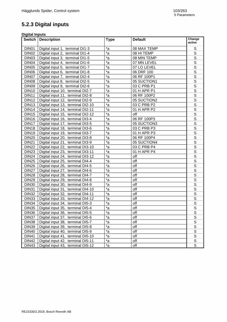
Hägglunds Spider, Control system 103/263 5 Parameters
RE15330/2.2019, Bosch Rexroth AB
5.2.3 Digital inputs Digital Inputs
Switch
Description Type Default Change active
DIN01 Digital input 1, terminal DI1-3 *a 08 MAX TEMP S
DIN02 Digital input 2, terminal DI1-4 *a 08 HI TEMP S
DIN03 Digital input 3, terminal DI1-5 *a 08 MIN TEMP S
DIN04 Digital input 4, terminal DI1-6 *a 07 MN LEVEL S
DIN05 Digital input 5, terminal DI1-7 *a 07 LO LEVEL S
DIN06 Digital input 6, terminal DI1-8 *a 06 DRF 100 S
DIN07 Digital input 7, terminal DI2-4 *a 06 RF 100P1 S
DIN08 Digital input 8, terminal DI2-5 *a 05 SUCTION1 S
DIN09 Digital input 9, terminal DI2-6 *a 03 C PRB P1 S
DIN10 Digital input 10, terminal DI2-7 *a 01 H APR P1 S
DIN11 Digital input 11, terminal DI2-8 *a 06 RF 100P2 S
DIN12 Digital input 12, terminal DI2-9 *a 05 SUCTION2 S
DIN13 Digital input 13, terminal DI2-10 *a 03 C PRB P2 S
DIN14 Digital input 14, terminal DI2-11 *a 01 H APR P2 S
DIN15 Digital input 15, terminal DI2-12 *a off S
DIN16 Digital input 16, terminal DI3-4 *a 06 RF 100P3 S
DIN17 Digital input 17, terminal DI3-5 *a 05 SUCTION3 S
DIN18 Digital input 18, terminal DI3-6 *a 03 C PRB P3 S
DIN19 Digital input 19, terminal DI3-7 *a 01 H APR P3 S
DIN20 Digital input 20, terminal DI3-8 *a 06 RF 100P4 S
DIN21 Digital input 21, terminal DI3-9 *a 05 SUCTION4 S
DIN22 Digital input 22, terminal DI3-10 *a 03 C PRB P4 S
DIN23 Digital input 23, terminal DI3-11 *a 01 H APR P4 S
DIN24 Digital input 24, terminal DI3-12 *a off S
DIN25 Digital input 25, terminal DI4-4 *a off S
DIN26 Digital input 26, terminal DI4-5 *a off S
DIN27 Digital input 27, terminal DI4-6 *a off S
DIN28 Digital input 28, terminal DI4-7 *a off S
DIN29 Digital input 29, terminal DI4-8 *a off S
DIN30 Digital input 30, terminal DI4-9 *a off S
DIN31 Digital input 31, terminal DI4-10 *a off S
DIN32 Digital input 32, terminal DI4-11 *a off S
DIN33 Digital input 33, terminal DI4-12 *a off S
DIN34 Digital input 34, terminal DI5-3 *a off S
DIN35 Digital input 35, terminal DI5-4 *a off S
DIN36 Digital input 36, terminal DI5-5 *a off S
DIN37 Digital input 37, terminal DI5-6 *a off S
DIN38 Digital input 38, terminal DI5-7 *a off S
DIN39 Digital input 39, terminal DI5-8 *a off S
DIN40 Digital input 40, terminal DI5-9 *a off S
DIN41 Digital input 41, terminal DI5-10 *a off S
DIN42 Digital input 42, terminal DI5-11 *a off S
DIN43 Digital input 43, terminal DI5-12 *a off S

Hägglunds Spider, Control system 104/263 5 Parameters
RE15330/2.2019, Bosch Rexroth AB
*a Possible digital input function settings: 01 H APR P1 High pressure A-side monitor function for pump 1 01 H BPR P1 High pressure B-side monitor function for pump 1 01 H APR P2 High pressure A-side monitor function for pump 2 01 H BPR P2 High pressure B-side monitor function for pump 2 01 H APR P3 High pressure A-side monitor function for pump 3 01 H BPR P3 High pressure B-side monitor function for pump 3 01 H APR P4 High pressure A-side monitor function for pump 4 01 H BPR P4 High pressure B-side monitor function for pump 4 02 H APR D1 High pressure A-side monitor function for drive 1 02 H BPR D1 High pressure B-side monitor function for drive 1 02 H APR D2 High pressure A-side monitor function for drive 2 02 H BPR D2 High pressure B-side monitor function for drive 2 02 H APR 12 High pressure A-side monitor function for drive 1 and 2 02 H BPR 12 High pressure B-side monitor function for drive 1 and 2 03 C PRA P1 Low charge pressure A-side monitor function for pump 1 03 C PRB P1 Low charge pressure B-side monitor function for pump 1 03 C PRA P2 Low charge pressure A-side monitor function for pump 2 03 C PRB P2 Low charge pressure B-side monitor function for pump 2 03 C PRA P3 Low charge pressure A-side monitor function for pump 3 03 C PRB P3 Low charge pressure B-side monitor function for pump 3 03 C PRA P4 Low charge pressure A-side monitor function for pump 4 03 C PRB P4 Low charge pressure B-side monitor function for pump 4 04 C PRA D1 Low charge pressure A-side monitor function for drive 1 04 C PRB D1 Low charge pressure B-side monitor function for drive 1 04 C PRA D2 Low charge pressure A-side monitor function for drive 2 04 C PRB D2 Low charge pressure B-side monitor function for drive 2 05 SUCTION1 Suction line monitor for pump 1 05 SUCTION2 Suction line monitor for pump 2 05 SUCTION3 Suction line monitor for pump 3 05 SUCTION4 Suction line monitor for pump 4 05 ACC A P1 Monitor of accumulator pressure A-side pump 1 05 ACC B P1 Monitor of accumulator pressure B-side pump 1 05 ACC A P2 Monitor of accumulator pressure A-side pump 2 05 ACC B P2 Monitor of accumulator pressure B-side pump 2 05 ACC A P3 Monitor of accumulator pressure A-side pump 3 05 ACC B P3 Monitor of accumulator pressure B-side pump 3 05 ACC A P4 Monitor of accumulator pressure A-side pump 4 05 ACC B P4 Monitor of accumulator pressure B-side pump 4 05 ACC A D1 Monitor of accumulator pressure A-side drive 1 05 ACC B D1 Monitor of accumulator pressure B-side drive 1 05 ACC A D2 Monitor of accumulator pressure A-side drive 2 05 ACC B D2 Monitor of accumulator pressure B-side drive 2 06 RF 75P1 Monitor of return filter for pump 1 clogged to 3/4 06 RF 100P1 Monitor of return filter for pump 1 fully clogged 06 CF 75P1 Monitor of charge filter for pump 1 clogged to 3/4 06 CF 100P1 Monitor of charge filter for pump 1 fully clogged 06 RF 75P2 Monitor of return filter for pump 2 clogged to 3/4 06 RF 100P2 Monitor of return filter for pump 2 fully clogged 06 CF 75P2 Monitor of charge filter for pump 2 clogged to 3/4 06 CF 100P2 Monitor of charge filter for pump 2 fully clogged 06 RF 75P3 Monitor of return filter for pump 3 clogged to 3/4 06 RF 100P3 Monitor of return filter for pump 3 fully clogged 06 CF 75P3 Monitor of charge filter for pump 3 clogged to 3/4 06 CF 100P3 Monitor of charge filter for pump 3 fully clogged 06 RF 75P4 Monitor of return filter for pump 4 clogged to 3/4 06 RF 100P4 Monitor of return filter for pump 4 fully clogged 06 CF 75P4 Monitor of charge filter for pump 4 clogged to 3/4 06 CF 100P4 Monitor of charge filter for pump 4 fully clogged 06 DF1 75 Monitor of drain filter 1 clogged to 3/4 06 DF1 100 Monitor of drain filter 1 fully clogged 06 DF2 75 Monitor of drain filter 2 clogged to 3/4 06 DF2 100 Monitor of drain filter 2 fully clogged 06 AUXF 75 Monitor of auxiliary filter clogged to 3/4 06 AUXF 100 Monitor of auxiliary filter fully clogged 06 F TEMP Interlock of filter warning inputs 07 LO LEVEL Low oil level monitor for tank 07 MN LEVEL Min oil level monitor for tank 08 MAX TEMP Max oil temp monitor for tank 08 HI TEMP High oil temp monitor for tank 08 MIN TEMP Low oil temp monitor for tank 09 ALARM R Remote reset of alarms and warnings 09 BUS R Reset of alarms and warnings via bus

Hägglunds Spider, Control system 105/263 5 Parameters
RE15330/2.2019, Bosch Rexroth AB
09 BUS 1 Switching to Bus command signals, Drive 1 09 BUS 2 Switching to Bus command signals, Drive 2 09 BUS M Switching to Bus command signal, External master 09 LAMPTEST Lamptest for selected digital outputs 09 EMSTOP Machine stop without hardware shutdown 10 SHR A D1 Shredder forward stop, Drive 1 10 SHR B D1 Shredder reverse stop, Drive 1 10 SHR A D2 Shredder forward stop, Drive 2 10 SHR B D2 Shredder reverse stop, Drive 2 10 SHR 1+2A Shredder forward stop, Drive 1 and 2 10 SHR 1+2B Shredder forward stop, Drive 1 and 2 10 INTERV1 Interval control of shredder, Drive 1 10 INTERV2 Interval control of shredder, Drive 2 10 SH RES 1 External reset of Shredder blocked function, Drive 1 10 SH RES 2 External reset of Shredder blocked function, Drive 2 10 SH RES12 External reset of Shredder blocked function, Drive 1 and 2 11 PL1 Activate power limitation for Drive 1 11 PL2 Activate power limitation for Drive 2 11 P1OFF Ramp down pump 1 11 P2OFF Ramp down pump 2 11 P3OFF Ramp down pump 3 11 P4OFF Ramp down pump 4 12 RES EN 1 External enable of counter reset in Synchro mode, Drive 1 12 RES EN2 External enable of counter reset in Synchro mode, Drive 2 12 FRICTION Friction drive in Synchro counter mode 12 INV M Inverting of master speed command in Synchro mode, Drive 1 13 AUX 1 Connected to Monitor Auxiliary input 1 13 AUX 2 Connected to Monitor Auxiliary input 2 13 AUX 3 Connected to Monitor Auxiliary input 3 13 AUX 4 Connected to Monitor Auxiliary input 4 13 AUX 5 Connected to Monitor Auxiliary input 5 13 AUX 6 Connected to Monitor Auxiliary input 6 13 AUX 7 Connected to Monitor Auxiliary input 7 13 AUX 8 Connected to Monitor Auxiliary input 8 13 AUX 9 Connected to Monitor Auxiliary input 9 13 AUX 10 Connected to Monitor Auxiliary input 10 13 AUX 11 Connected to Monitor Auxiliary input 11 13 AUX 12 Connected to Monitor Auxiliary input 12 13 AUX 13 Connected to Monitor Auxiliary input 13 13 AUX 14 Connected to Monitor Auxiliary input 14 13 AUX 15 Connected to Monitor Auxiliary input 15 13 AUX 16 Connected to Monitor Auxiliary input 16 13 AUX 17 Connected to Monitor Auxiliary input 17 13 AUX 18 Connected to Monitor Auxiliary input 18 13 AUX 19 Connected to Monitor Auxiliary input 19 13 AUX 20 Connected to Monitor Auxiliary input 20 14 START 1 Drive start in Remote mode, Drive 1 14 START 2 Drive start in Remote mode, Drive 2 14 START 12 Drive start in Remote mode, Drive 1 and Drive 2 14 L START1 Drive start in Local mode, Drive 1 NOTE1 14 L STOP1 Drive stop in Local mode, Drive 1 NOTE1 14 L START2 Drive start in Local mode, Drive 2 NOTE1 14 L STOP2 Drive stop in Local mode, Drive 2 NOTE1 15 FIXED 1A Drive with fixed speed A, Drive 1 15 FIXED 1B Drive with fixed speed B, Drive 1 15 FIXED 1C Drive with fixed speed C, Drive 1 15 FIXED 1D Drive with fixed speed D, Drive 1 15 FIXED 2A Drive with fixed speed A, Drive 2 15 FIXED 2B Drive with fixed speed B, Drive 2 15 FIXED 2C Drive with fixed speed C, Drive 2 15 FIXED 2D Drive with fixed speed D, Drive 2 15 FIX 1+2A Drive with fixed speed A, Drive 1 and Drive 2 15 FIX 1+2B Drive with fixed speed B, Drive 1 and Drive 2 15 L REV 1 Local Reverse drive with fixed speed, Drive 1 or local reverse drive in manual mode, Shredder Drive 1 15 L FORW 1 Local forward drive in manual mode, Shredder Drive 1 15 L REV 2 Local Reverse drive with fixed speed, Drive 2 or local reverse drive in manual mode, Shredder Drive 2 15 L FORW 2 Local forward drive in manual mode, Shredder Drive 2 15 INV 1 Reverse with inverted command at unidirectional command, Drive 1 15 INV 2 Reverse with inverted command at unidirectional command, Drive 2 15 RAMP1OFF Bypass of ramp, Drive 1 15 RAMP2OFF Bypass of ramp, Drive 2 16 SP UP1 Increase set point in Local mode, Drive 1 16 SP DN1 Decrease set point in Local mode, Drive 1 16 SP UP2 Increase set point in Local mode, Drive 2

Hägglunds Spider, Control system 106/263 5 Parameters
RE15330/2.2019, Bosch Rexroth AB
16 SP DN2 Decrease set point in Local mode, Drive 2 16 SP RES1 Reset of set point in Local mode, Drive 1 16 SP RES2 Reset of set point in Local mode, Drive 2 16 REM 1 Activated input = remote mode Drive 1, Open input = local mode 16 REM 2 Activated input = remote mode Drive 2, Open input = local mode 16 REM 1+2 Activated input = remote mode Drive 1 and 2, Open input = local mode 17 AUTO 1 Activated input = auto mode Drive 1, Open input = manual mode 17 AUTO 2 Activated input = auto mode Drive 2, Open input = manual mode 17 AUTO 1+2 Activated input = auto mode Drive 1 and 2, Open input = manual mode 18 REG 1 Activated input = Closed loop speed feedback active Drive 1, Open input = Open loop 18 REG 2 Activated input = Closed loop speed feedback active Drive 2, Open input = Open loop 18 REG 1+2 Activated input = Closed loop speed feedback active Drive 1+2, Open input = Open loop 18 ERR1 RES External reset of Error too large function, Drive 1 18 ERR2 RES External reset of Error too large function, Drive 2 18 ERR1+2 R External reset of Error too large function, Drive 1 and 2 19 EMOTOR 1 High temp electric motor 1 monitor function 19 EMOTOR 2 High temp electric motor 2 monitor function 19 EMOTOR 3 High temp electric motor 3 monitor function 19 AUX ST Start Electric motor for auxiliary pump 19 FLUSH ON Electric motor for flush pump started 19 C PUMPD1 Charge pump for drive1 started 19 C PUMPD2 Charge pump for drive 2 started 19 SUCT AUX Suction line for auxiliary pump 19 AUX EMOT High temp auxiliary electric motor monitor function 19 BRAKE1OP Brake opened for drive 1 19 BRAKE2OP Brake opened for drive 2 19 EM1START Electric motor 1 started 19 EM2START Electric motor 2 started 19 EM3START Electric motor 3 started 20 PR REM 1 Switching between local and remote pressure setpoint, drive 1 20 PR REM 2 Switching between local and remote pressure setpoint, drive 2 20 PR HI 1 Force pressure output to high level, drive 1 20 PR LO 1 Force pressure output to low level, drive 1 20 PR ON 1 Switch on pressure regulator, drive 1 20 PR HI 2 Force pressure output to high level, drive 2 20 PR LO 2 Force pressure output to low level, drive 2 20 PR ON 2 Switch on pressure regulator, drive 2 21 MEM01..24 Set Memory cell off Not used off/used Input used internally or for digital output NOTE1 The input will be active for drive start/stop in:
* local mode * in remote mode if a digital input not is used for start

Hägglunds Spider, Control system 107/263 5 Parameters
RE15330/2.2019, Bosch Rexroth AB
5.2.4 Digital outputs
Digital Outputs -Digital out 1
Switch
Description Type Default Min Max Change active
DOA01 Digital output function, terminal DO1:3-4
*a off S
DOA02 Inverted function yes/no no S
DOA03 Delay time for digital output 0,1sec 5,0 0,0 60,0 S
DOA04 Delay function for output ON=On delay OFF=Off delay ONOFF= Delay both on and off PULSE=Output changes during delay time NO=No delay
ON OFF ONOFF PULSE NO
NO
S
DOA05 Connected for lamptest yes/no no S
Digital Outputs -Digital out 2
Switch
Description Type Default Min Max Change active
DOB01 Digital output function, terminal DO1:5-6
*a off S
DOB02 Inverted function yes/no no S
DOB03 Delay time for digital output 0,1sec 5,0 0,0 60,0 S
DOB04 Delay function for output ON=On delay OFF=Off delay ONOFF= Delay both on and off PULSE=Output changes during delay time NO=No delay
ON OFF ONOFF PULSE NO
NO
S
DOB05 Connected for lamptest yes/no no S
Digital Outputs -Digital out 3
Switch
Description Type Default Min Max Change active
DOC01 Digital output function, terminal DO1:7-8
*a off S
DOC02 Inverted function yes/no no S
DOC03 Delay time for digital output 0,1sec 5,0 0,0 60,0 S
DOC04 Delay function for output ON=On delay OFF=Off delay ONOFF= Delay both on and off PULSE=Output changes during delay time NO=No delay
ON OFF ONOFF PULSE NO
NO
S
DOC05 Connected for lamptest yes/no no S

Hägglunds Spider, Control system 108/263 5 Parameters
RE15330/2.2019, Bosch Rexroth AB
Digital Outputs -Digital out 4
Switch
Description Type Default Min Max Change active
DOD01 Digital output function, terminal DO1:9-10
*a off S
DOD02 Inverted function yes/no no S
DOD03 Delay time for digital output 0,1sec 5,0 0,0 60,0 S
DOD04 Delay function for output ON=On delay OFF=Off delay ONOFF= Delay both on and off PULSE=Output changes during delay time NO=No delay
ON OFF ONOFF PULSE NO
NO
S
DOD05 Connected for lamptest yes/no no S
Digital Outputs -Digital out 5
Switch
Description Type Default Min Max Change active
DOE01 Digital output function, terminal DO1:11-12
*a off S
DOE02 Inverted function yes/no no S
DOE03 Delay time for digital output 0,1sec 5,0 0,0 60,0 S
DOE04 Delay function for output ON=On delay OFF=Off delay ONOFF= Delay both on and off PULSE=Output changes during delay time NO=No delay
ON OFF ONOFF PULSE NO
NO
S
DOE05 Connected for lamptest yes/no no S
Digital Outputs -Digital out 6
Switch
Description Type Default Min Max Change active
DOF01 Digital output function, terminal DO1:13-14
*a off S
DOF02 Inverted function yes/no no S
DOF03 Delay time for digital output 0,1sec 5,0 0,0 60,0 S
DOF04 Delay function for output ON=On delay OFF=Off delay ONOFF= Delay both on and off PULSE=Output changes during delay time NO=No delay
ON OFF ONOFF PULSE NO
NO
S
DOF05 Connected for lamptest yes/no no S

Hägglunds Spider, Control system 109/263 5 Parameters
RE15330/2.2019, Bosch Rexroth AB
Digital Outputs -Digital out 7
Switch
Description Type Default Min Max Change active
DOG01 Digital output function, terminal DO2:3-4
*a off S
DOG02 Inverted function yes/no no S
DOG03 Delay time for digital output 0,1sec 5,0 0,0 60,0 S
DOG04 Delay function for output ON=On delay OFF=Off delay ONOFF= Delay both on and off PULSE=Output changes during delay time NO=No delay
ON OFF ONOFF PULSE NO
NO
S
DOG05 Connected for lamptest yes/no no S
Digital Outputs -Digital out 8
Switch
Description Type Default Min Max Change active
DOH01 Digital output function, terminal DO2:5-6
*a off S
DOH02 Inverted function yes/no no S
DOH03 Delay time for digital output 0,1sec 5,0 0,0 60,0 S
DOH04 Delay function for output ON=On delay OFF=Off delay ONOFF= Delay both on and off PULSE=Output changes during delay time NO=No delay
ON OFF ONOFF PULSE NO
NO
S
DOH05 Connected for lamptest yes/no no S
Digital Outputs -Digital out 9
Switch
Description Type Default Min Max Change active
DOI01 Digital output function, terminal DO2:7-8
*a off S
DOI02 Inverted function yes/no no S
DOI03 Delay time for digital output 0,1sec 5,0 0,0 60,0 S
DOI04 Delay function for output ON=On delay OFF=Off delay ONOFF= Delay both on and off PULSE=Output changes during delay time NO=No delay
ON OFF ONOFF PULSE NO
NO
S
DOI05 Connected for lamptest yes/no no S

Hägglunds Spider, Control system 110/263 5 Parameters
RE15330/2.2019, Bosch Rexroth AB
Digital Outputs -Digital out 10
Switch
Description Type Default Min Max Change active
DOJ01 Digital output function, terminal DO2:9-10
*a off S
DOJ02 Inverted function yes/no no S
DOJ03 Delay time for digital output 0,1sec 5,0 0,0 60,0 S
DOJ04 Delay function for output ON=On delay OFF=Off delay ONOFF= Delay both on and off PULSE=Output changes during delay time NO=No delay
ON OFF ONOFF PULSE NO
NO
S
DOJ05 Connected for lamptest yes/no no S
Digital Outputs -Digital out 11
Switch
Description Type Default Min Max Change active
DOK01 Digital output function, terminal DO2:11-12
*a off S
DOK02 Inverted function yes/no no S
DOK03 Delay time for digital output 0,1sec 5,0 0,0 60,0 S
DOK04 Delay function for output ON=On delay OFF=Off delay ONOFF= Delay both on and off PULSE=Output changes during delay time NO=No delay
ON OFF ONOFF PULSE NO
NO
S
DOK05 Connected for lamptest yes/no no S
Digital Outputs -Digital out 12
Switch
Description Type Default Min Max Change active
DOL01 Digital output function, terminal DO2:11-13
*a off S
DOL02 Inverted function yes/no no S
DOL03 Delay time for digital output 0,1sec 5,0 0,0 60,0 S
DOL04 Delay function for output ON=On delay OFF=Off delay ONOFF= Delay both on and off PULSE=Output changes during delay time NO=No delay
ON OFF ONOFF PULSE NO
NO
S
DOL05 Connected for lamptest yes/no no S

Hägglunds Spider, Control system 111/263 5 Parameters
RE15330/2.2019, Bosch Rexroth AB
Digital Outputs -Digital out 13
Switch
Description Type Default Min Max Change active
DOM01 Digital output function, terminal DO2:11-14
*a off S
DOM02 Inverted function yes/no no S
DOM03 Delay time for digital output 0,1sec 5,0 0,0 60,0 S
DOM04 Delay function for output ON=On delay OFF=Off delay ONOFF= Delay both on and off PULSE=Output changes during delay time NO=No delay
ON OFF ONOFF PULSE NO
NO
S
DOM05 Connected for lamptest yes/no no S *a Possible function settings:
01 A1 Alarm, Drive 1 01 A2 Alarm, Drive 2 01 A1+A2 Alarm, Drive 1 or Drive2 01 W 1 Warning, Drive 1 01 W 2 Warning, Drive 2 01 W1+W2 Warning, Drive 1 or Drive 2 01 INT 1 Interlock, Drive 1 01 INT 2 Interlock, Drive 2 01 INT 1+2 Interlock, Drive 1 or Drive 2 01 D1 Disable, Drive 1 01 D2 Disable, Drive 2 01 D1+D2 Disable, Drive 1 or Drive 2 02 START 1 Drive 1 started 02 START 2 Drive 2 started 02 START1+2 Drive 1 or Drive 2 started 02 START1*2 Drive 1 and Drive 2 started 03 READY 1 Ready to use, Drive1 (also to be used for Fail safe valve, Drive 1) 03 READY 2 Ready to use, Drive2 (also to be used for Fail safe valve, Drive 2) 03 READY1+2 Drive 1 or Drive 2 ready 03 READY1*2 Drive 1 and Drive 2 ready 04 REMOTE 1 Drive 1 in remote mode 04 REMOTE 2 Drive 2 in remote mode 04 BUS 1 Drive 1 in bus mode 04 BUS 2 Drive 2 in bus mode 04 BUS M Extermal synchro master in bus mode 05 AUTO 1 Drive 1 in automatic mode (Shredder) 05 AUTO 2 Drive 2 in automatic mode (Shredder) 05 REG 1 Drive 1 in regulated mode (Basic and Synchro) 05 REG 2 Drive 2 in regulated mode (Basic and Synchro) 06 PLIM 1 Power limit active, Drive 1 06 PLIM 2 Power limit active, Drive 2 06 PLIM 1+2 Power limit active, Drive 1 or Drive 2 06 PLIM Power limit active 06 P10FF Pump 1 downramped 06 P20FF Pump 2 downramped 06 P30FF Pump 3 downramped 06 P40FF Pump 4 downramped 07 FORW 1 Drive 1 running forward (positive command signal) 07 REV 1 Drive 1 running reverse (negative command signal) 07 FORW 2 Drive 2 running forward (positive command signal) 07 REV 2 Drive 2 running reverse (negative command signal) 08 C ZERO Indication for found zero position in Synchro counter function (synchro activated) 08 SYNCHRO Synchro within limits set in parameter SYD01 09 AOUT 1- Selected register reading for analogue output 1 has negative sign 09 AOUT 2- Selected register reading for analogue output 2 has negative sign 09 AOUT 3- Selected register reading for analogue output 3 has negative sign 09 AOUT 4- Selected register reading for analogue output 4 has negative sign 10 EMOT D1 Electric motor(s) for drive 1 started 10 EMOT D2 Electric motor(s) for drive 2 started 10 EMOTD1+2 Electric motor(s) for drive 1 or 2 started 10 EMOTD1*2 Electric motor(s) for drive 1 and 2 started

Hägglunds Spider, Control system 112/263 5 Parameters
RE15330/2.2019, Bosch Rexroth AB
10 EMOTOR 1 Electric motor 1 started 10 EMOTOR 2 Electric motor 2 started 10 EMOTOR 3 Electric motor 3 started 10 EM INT1 Electric motor 1 interlock (not monitored contact) 10 EM INT2 Electric motor 2 interlock (not monitored contact) 10 EM INT3 Electric motor 3 interlock (not monitored contact) 10 CP INT1 Charge pump motor interlock, drive 1 (not monitored contact) 10 CP INT2 Charge pump motor interlock, drive 2 (not monitored contact) 11 MIN TEMP Min temp active indicator 11 HI TEMP High temp active indicator 11 MAX TEMP Max temp active indicator 11 HI TEMPI High temp interlock active indicator 11 COOL CONI Cooler control interlocked by electric motor start when using analog temp sensor 11 COOL COND Cooler control without interlock when using analog temp sensor 11 COOL FWD Cooler control timed forward when using analog temp sensor 11 COOL REV Cooler control timed reverse when using analog temp sensor 11 HEAT CON Heater control when using analog temp sensor 11 FLUSHCON Flushing valve control when using analog temp sensor 11 ST AUXP Start auxiliary pump electric motor 11 FL TEMP Standby flush temp active 11 MN DRTMP Min drain temp disable 11 MX LEVEL Max oil level (overfill) in tank when using analog level sensor 11 FULL Max fill-up level in tank when using analog level sensor 11 LO LEVEL Low oil level in tank when using analog level sensor 11 MN LEVEL Minimum oil level in tank when using analog level sensor 12 P1 C ACT Pressure control active, drive 1 12 P1 HI CA Pressure control high active, drive 1 12 P1 LO CA Pressure control low active, drive 1 12 P1 MAX Pressure control saturated, drive 1 12 P2 C ACT Pressure control active, drive 2 12 P2 HI CA Pressure control high active, drive 2 12 P2 LO CA Pressure control low active, drive 2 12 P2 MAX Pressure control saturated, drive 2 13 SH BLCK1 Shredder blocked, drive 1 13 SH BLCK2 Shredder blocked, drive 2 13 RESET1 Front panel Alarm reset active, Drive 1 13 RESET2 Front panel Alarm reset active, Drive 2 13 RESET1+2 Front panel Alarm reset active, Drive 1 or Drive 2 13 OPEN BR1 Open brake, Drive 1 13 OPEN BR2 Open brake, Drive 2 14 AUX1 Auxillary function 1 active 14 AUX2 Auxillary function 2 active 14 AUX3 Auxillary function 3 active 14 AUX4 Auxillary function 4 active 14 AUX5 Auxillary function 5 active 14 AUX6 Auxillary function 6 active 14 AUX7 Auxillary function 7 active 14 AUX8 Auxillary function 8 active 14 AUX9 Auxillary function 9 active 14 AUX10 Auxillary function 10 active 14 AUX11 Auxillary function 11 active 14 AUX12 Auxillary function 12 active 14 AUX13 Auxillary function 13 active 14 AUX14 Auxillary function 14 active 14 AUX15 Auxillary function 15 active 14 AUX16 Auxillary function 16 active 14 AUX17 Auxillary function 17 active 14 AUX18 Auxillary function 18 active 14 AUX19 Auxillary function 19 active 14 AUX20 Auxillary function 20 active 15 DIN1 Digital input 1 status 15 DIN2 Digital input 2 status 15 DIN3 Digital input 3 status 15 DIN4 Digital input 4 status 15 DIN5 Digital input 5 status 15 DIN6 Digital input 6 status 15 DIN7 Digital input 7 status 15 DIN8 Digital input 8 status 15 DIN9 Digital input 9 status 15 DIN10 Digital input 10 status 15 DIN11 Digital input 11 status 15 DIN12 Digital input 12 status 15 DIN13 Digital input 13 status 15 DIN14 Digital input 14 status 15 DIN15 Digital input 15 status 15 DIN16 Digital input 16 status

Hägglunds Spider, Control system 113/263 5 Parameters
RE15330/2.2019, Bosch Rexroth AB
15 DIN17 Digital input 17 status 15 DIN18 Digital input 18 status 15 DIN19 Digital input 19 status 15 DIN20 Digital input 20 status 15 DIN21 Digital input 21 status 15 DIN22 Digital input 22 status 15 DIN23 Digital input 23 status 15 DIN24 Digital input 24 status 15 DIN25 Digital input 25 status 15 DIN26 Digital input 26 status 15 DIN27 Digital input 27 status 15 DIN28 Digital input 28 status 15 DIN29 Digital input 29 status 15 DIN30 Digital input 30 status 15 DIN31 Digital input 31 status 15 DIN32 Digital input 32 status 15 DIN33 Digital input 33 status 15 DIN34 Digital input 34 status 15 DIN35 Digital input 35 status 15 DIN36 Digital input 36 status 15 DIN37 Digital input 37 status 15 DIN38 Digital input 38 status 15 DIN39 Digital input 39 status 15 DIN40 Digital input 40 status 15 DIN41 Digital input 41 status 15 DIN42 Digital input 42 status 15 DIN43 Digital input 43 status 16 BDIN1 Bus Digital input 1 status 16 BDIN2 Bus Digital input 2 status 16 BDIN3 Bus Digital input 3 status 16 BDIN4 Bus Digital input 4 status 16 BDIN5 Bus Digital input 5 status 16 BDIN6 Bus Digital input 6 status 16 BDIN7 Bus Digital input 7 status 16 BDIN8 Bus Digital input 8 status 16 BDIN9 Bus Digital input 9 status 16 BDIN10 Bus Digital input 10 status 16 BDIN11 Bus Digital input 11 status 16 BDIN12 Bus Digital input 12 status 16 BDIN13 Bus Digital input 13 status 16 BDIN14 Bus Digital input 14 status 16 BDIN15 Bus Digital input 15 status 16 BDIN16 Bus Digital input 16 status 16 BDIN17 Bus Digital input 17 status 16 BDIN18 Bus Digital input 18 status 16 BDIN19 Bus Digital input 19 status 16 BDIN20 Bus Digital input 20 status 16 BDIN21 Bus Digital input 21 status 16 BDIN22 Bus Digital input 22 status 16 BDIN23 Bus Digital input 23 status 16 BDIN24 Bus Digital input 24 status 17C PRA P1 Low charge pressure A-side for pump 1 17C PRB P1 Low charge pressure B-side for pump 1 17C PRA P2 Low charge pressure A-side for pump 2 17C PRB P2 Low charge pressure B-side for pump 2 17C PRA P3 Low charge pressure A-side for pump 3 17C PRB P3 Low charge pressure B-side for pump 3 17C PRA P4 Low charge pressure A-side for pump 4 17C PRB P4 Low charge pressure B-side for pump 4 18 B COL11 Toggled by 1:st front panel drive button in 1:st column. 18 B COL 12 Toggled by 2:nd front panel drive button in 1:st column. 18 B COL 21 Toggled by 1:st front panel drive button in 2:nd column. 18 B COL 22 Toggled by 2:nd front panel drive button in 2:nd column. 18 B COL 31 Toggled by 1:st front panel drive button in 3:rd column. 18 B COL 32 Toggled by 2:nd front panel drive button in 3:rd column. 18 B COL 41 Toggled by 1:st front panel drive button in 4:th column. 18 B COL 42 Toggled by 2:nd front panel drive button in 4:th column. 19 MEM01..24 Memory cell status off Not used

Hägglunds Spider, Control system 114/263 5 Parameters
RE15330/2.2019, Bosch Rexroth AB
5.2.5 Pulse inputs Pulse inputs-Selection
Switch
Description Type Default Min Max Change active
P0I01 Pulse input selection for Drive 1 DE1 DE2
DE1 S
P0I02 Pulse input selection for Drive 2 DE1 DE2
DE2
S
Pulse inputs-Drive 1
Switch
Description Type Default Min Max Change active
P1I01 Pulses/rev 1 1000 1 10000 S
P1I02 Units for REG109 *a rpm S
P1I03 Number of decimals for REG109 1 0 0 2 S
P1I04 Scaling for REG109 0.01 1.00 0.01 20.00 S
P1I05 Filter time for speed reading 0.1sec 0.0 0.0 5.0 S
P1I06 Polarity for digital speed signal 1=Normal 2=Inverted
1 2
1
S
P1I07 Encoder type 1=Quad 2=Single pulse with direction 3=Single pulse without direction
1 2 3
1
S
P1I08 High indication level (rpm) 0.1 0.0 -2000.0 2000.0 S
P1I09 Low indication level (rpm) 0.1 0.0 -2000.0 2000.0 S
P1I10 Function for high indication *b off S
P1I11 Function for low indication *b off S
Pulse inputs-Drive 2
Switch
Description Type Default Min Max Change active
P2I01 Pulses/rev 1 1000 1 10000 S
P2I02 Units for REG209 *a rpm S
P2I03 Number of decimals for REG209 1 0 0 2 S
P2I04 Scaling for REG209 0.01 1.00 0.01 20.00 S
P2I05 Filter time for speed reading 0.1sec 0.0 0.0 5.0 S
P2I06 Polarity for digital speed signal 1=Normal 2=Inverted
1 2
1
S
P2I07 Encoder type 1=Quad 2=Single pulse with direction 3=Single pulse without direction
1 2 3
1
S
P2I08 High indication level (rpm) 0.1 0.0 -2000.0 2000.0 S
P2I09 Low indication level (rpm) 0.1 0.0 -2000.0 2000.0 S
P2I10 Function for high indication *b off S
P2I11 Function for low indication *b off S
*a Possible units of measure settings: rpm, m/m, m/s, f/m, f/s *b Possible function settings:
13 AUX1-AUX20 Auxiliary monitor function Off Not used

Hägglunds Spider, Control system 115/263 5 Parameters
RE15330/2.2019, Bosch Rexroth AB
5.2.6 Analog inputs Analog inputs-Setpoint 1 (isolated)
Switch
Description Type Default Min Max Change active
AIA01 Input type, speed Set point Drive 1 *a 4-20mA S
AIA02 Zero point adjustment Set point Drive1 1bit 0bit -102bit 102bit A
AIA03 Max point adjustment Set point Drive1 1bit 0bit -102bit 102bit A
AIA04 Reading for REG101 %=% value Actual = Actual external input value (AIA01)
% Actual
% S
AIA05 Setpoint scaling 0,01 1.00 1.00 10.00 S
Analog inputs-Setpoint 2 (isolated)
Switch
Description Type Default Min Max Change active
AIB01 Input type, speed Set point Drive 2 *a 4-20mA S
AIB02 Zero point adjustment Set point Drive2 1bit 0bit -102bit 102bit A
AIB03 Max point adjustment Set point Drive2 1bit 0bit -102bit 102bit A
AIB04 Reading for REG201 %=% value Actual = Actual external input value (AIB01)
% Actual
% S
AIB05 Setpoint scaling 0,01 1.00 1.00 10.00 S
Analog inputs-Analog in 1 (isolated)
Switch
Description Type Default Min Max Change active
AIF01 Input type *a 4-20mA S
AIF02 Zero point adjustment 1bit 0bit -102bit 102bit A
AIF03 Max point adjustment 1bit 0bit -102bit 102bit A
AIF04 Min input, REG401 1 0 -1000 4000 A
AIF05 Max input, REG401 1 200 (AIF04) 9999 A
AIF06 Units for REG401 *c bar S
AIF07 Number of decimals for REG401 1 0 0 2 A
AIF08 Scaling for REG401 0.01 1.00 0.01 20.00 A
AIF09 Function for input *e off A
AIF10 High indication level AIF07 AIF05 AIF04 AIF05 S
AIF11 Low indication level AIF07 AIF04 AIF04 AIF05 S
AIF12 Function for min indication at 4-20mA input type
*f off S
AIF13 Function for high indication *b off S
AIF14 Function for low indication *b off S
AIF15 Filter time for analog input reading 0.1sec 0.0 0.0 5.0 A
AIF16 Filter time for analog input signal 0.01sec 0.00 0.00 5.00 A
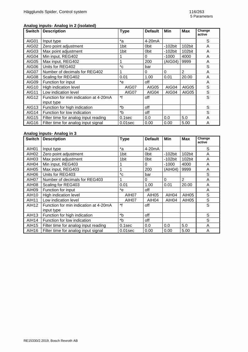
Hägglunds Spider, Control system 116/263 5 Parameters
RE15330/2.2019, Bosch Rexroth AB
Analog inputs- Analog in 2 (isolated)
Switch
Description Type Default Min Max Change active
AIG01 Input type *a 4-20mA S
AIG02 Zero point adjustment 1bit 0bit -102bit 102bit A
AIG03 Max point adjustment 1bit 0bit -102bit 102bit A
AIG04 Min input, REG402 1 0 -1000 4000 A
AIG05 Max input, REG402 1 200 (AIG04) 9999 A
AIG06 Units for REG402 *c bar S
AIG07 Number of decimals for REG402 1 0 0 2 A
AIG08 Scaling for REG402 0.01 1.00 0.01 20.00 A
AIG09 Function for input *e off A
AIG10 High indication level AIG07 AIG05 AIG04 AIG05 S
AIG11 Low indication level AIG07 AIG04 AIG04 AIG05 S
AIG12 Function for min indication at 4-20mA input type
*f off S
AIG13 Function for high indication *b off S
AIG14 Function for low indication *b off S
AIG15 Filter time for analog input reading 0.1sec 0.0 0.0 5.0 A
AIG16 Filter time for analog input signal 0.01sec 0.00 0.00 5.00 A
Analog inputs- Analog in 3
Switch
Description Type Default Min Max Change active
AIH01 Input type *a 4-20mA S
AIH02 Zero point adjustment 1bit 0bit -102bit 102bit A
AIH03 Max point adjustment 1bit 0bit -102bit 102bit A
AIH04 Min input, REG403 1 0 -1000 4000 A
AIH05 Max input, REG403 1 200 (AIH04) 9999 A
AIH06 Units for REG403 *c bar S
AIH07 Number of decimals for REG403 1 0 0 2 A
AIH08 Scaling for REG403 0.01 1.00 0.01 20.00 A
AIH09 Function for input *e off A
AIH10 High indication level AIH07 AIH05 AIH04 AIH05 S
AIH11 Low indication level AIH07 AIH04 AIH04 AIH05 S
AIH12 Function for min indication at 4-20mA input type
*f off S
AIH13 Function for high indication *b off S
AIH14 Function for low indication *b off S
AIH15 Filter time for analog input reading 0.1sec 0.0 0.0 5.0 A
AIH16 Filter time for analog input signal 0.01sec 0.00 0.00 5.00 A

Hägglunds Spider, Control system 117/263 5 Parameters
RE15330/2.2019, Bosch Rexroth AB
Analog inputs- Analog in 4
Switch
Description Type Default Min Max Change active
AII01 Input type *a 4-20mA S
AII02 Zero point adjustment 1bit 0bit -102bit 102bit A
AII03 Max point adjustment 1bit 0bit -102bit 102bit A
AII04 Min input, REG404 1 0 -1000 4000 A
AII05 Max input, REG404 1 200 (AII04) 9999 A
AII06 Units for REG404 *c bar S
AII07 Number of decimals for REG404 1 0 0 2 A
AII08 Scaling for REG404 0.01 1.00 0.01 20.00 A
AII09 Function for input *e off A
AII10 High indication level AII07 AII05 AII04 AII05 S
AII11 Low indication level AII07 AII04 AII04 AII05 S
AII12 Function for min indication at 4-20mA input type
*f off S
AII13 Function for high indication *b off S
AII14 Function for low indication *b off S
AII15 Filter time for analog input reading 0.1sec 0.0 0.0 5.0 A
AII16 Filter time for analog input signal 0.01sec 0.00 0.00 5.00 A
Analog inputs- Analog in 5
Switch
Description Type Default Min Max Change active
AIJ01 Input type *a 4-20mA S
AIJ02 Zero point adjustment 1bit 0bit -102bit 102bit A
AIJ03 Max point adjustment 1bit 0bit -102bit 102bit A
AIJ04 Min input, REG405 1 0 -1000 4000 A
AIJ05 Max input, REG405 1 200 (AIJ04) 9999 A
AIJ06 Units for REG405 *c bar S
AIJ07 Number of decimals for REG405 1 0 0 2 A
AIJ08 Scaling for REG405 0.01 1.00 0.01 20.00 A
AIJ09 Function for input *e off A
AIJ10 High indication level AIJ07 AIJ05 AIJ04 AIJ05 S
AIJ11 Low indication level AIJ07 AIJ04 AIJ04 AIJ05 S
AIJ12 Function for min indication at 4-20mA input type
*f off S
AIJ13 Function for high indication *b off S
AIJ14 Function for low indication *b off S
AIJ15 Filter time for analog input reading 0.1sec 0.0 0.0 5.0 A
AIJ16 Filter time for analog input signal 0.01sec 0.00 0.00 5.00 A

Hägglunds Spider, Control system 118/263 5 Parameters
RE15330/2.2019, Bosch Rexroth AB
Analog inputs- Analog in 6
Switch
Description Type Default Min Max Change active
AIK01 Input type *a 4-20mA S
AIK02 Zero point adjustment 1bit 0bit -102bit 102bit A
AIK03 Max point adjustment 1bit 0bit -102bit 102bit A
AIK04 Min input, REG406 1 0 -1000 4000 A
AIK05 Max input, REG406 1 200 (AIK04) 9999 A
AIK06 Units for REG406 *c bar S
AIK07 Number of decimals for REG406 1 0 0 2 A
AIK08 Scaling for REG406 0.01 1.00 0.01 20.00 A
AIK09 Function for input *e off A
AIK10 High indication level AIK07 AIK05 AIK04 AIK05 S
AIK11 Low indication level AIK07 AIK04 AIK04 AIK05 S
AIK12 Function for min indication at 4-20mA input type
*f off S
AIK13 Function for high indication *b off S
AIK14 Function for low indication *b off S
AIK15 Filter time for analog input reading 0.1sec 0.0 0.0 5.0 A
AIK16 Filter time for analog input signal 0.01sec 0.00 0.00 5.00 A
Analog inputs- Analog in 7
Switch
Description Type Default Min Max Change active
AIL01 Input type *a 4-20mA S
AIL02 Zero point adjustment 1bit 0bit -102bit 102bit A
AIL03 Max point adjustment 1bit 0bit -102bit 102bit A
AIL04 Min input, REG407 1 0 -1000 4000 A
AIL05 Max input, REG407 1 200 (AIL04) 9999 A
AIL06 Units for REG407 *c bar S
AIL07 Number of decimals for REG407 1 0 0 2 A
AIL08 Scaling for REG407 0.01 1.00 0.01 20.00 A
AIL09 Function for input *e off A
AIL10 High indication level AIL07 AIL05 AIL04 AIL05 S
AIL11 Low indication level AIL07 AIL04 AIL04 AIL05 S
AIL12 Function for min indication at 4-20mA input type
*f off S
AIL13 Function for high indication *b off S
AIL14 Function for low indication *b off S
AIL15 Filter time for analog input reading 0.1sec 0.0 0.0 5.0 A
AIL16 Filter time for analog input signal 0.01sec 0.00 0.00 5.00 A

Hägglunds Spider, Control system 119/263 5 Parameters
RE15330/2.2019, Bosch Rexroth AB
Analog inputs- Analog in 8
Switch
Description Type Default Min Max Change active
AIM01 Input type *a 4-20mA S
AIM02 Zero point adjustment 1bit 0bit -102bit 102bit A
AIM03 Max point adjustment 1bit 0bit -102bit 102bit A
AIM04 Min input, REG408 1 0 -1000 4000 A
AIM05 Max input, REG408 1 200 (AIM04) 9999 A
AIM06 Units for REG408 *c bar S
AIM07 Number of decimals for REG408 1 0 0 2 A
AIM08 Scaling for REG408 0.01 1.00 0.01 20.00 A
AIM09 Function for input *e off A
AIM10 High indication level AIM07 AIM05 AIM04 AIM05
S
AIM11 Low indication level AIM07 AIM04 AIM04 AIM05
S
AIM12 Function for min indication at 4-20mA input type
*f off S
AIM13 Function for high indication *b off S
AIM14 Function for low indication *b off S
AIM15 Filter time for analog input reading 0.1sec 0.0 0.0 5.0 A
AIM16 Filter time for analog input signal 0.01sec 0.00 0.00 5.00 A
Analog inputs- Analog in 9
Switch
Description Type Default Min Max Change active
AIN01 Input type *a 4-20mA S
AIN02 Zero point adjustment 1bit 0bit -102bit 102bit A
AIN03 Max point adjustment 1bit 0bit -102bit 102bit A
AIN04 Min input, REG409 1 0 -1000 4000 A
AIN05 Max input, REG409 1 200 (AIN04) 9999 A
AIN06 Units for REG409 *c bar S
AIN07 Number of decimals for REG409 1 0 0 2 A
AIN08 Scaling for REG409 0.01 1.00 0.01 20.00 A
AIN09 Function for input *e off A
AIN10 High indication level AIN07 AIN05 AIN04 AIN05 S
AIN11 Low indication level AIN07 AIN04 AIN04 AIN05 S
AIN12 Function for min indication at 4-20mA input type
*f off S
AIN13 Function for high indication *b off S
AIN14 Function for low indication *b off S
AIN15 Filter time for analog input reading 0.1sec 0.0 0.0 5.0 A
AIN16 Filter time for analog input signal 0.01sec 0.00 0.00 5.00 A

Hägglunds Spider, Control system 120/263 5 Parameters
RE15330/2.2019, Bosch Rexroth AB
Analog inputs-Tank temp
Switch
Description Type Default Min Max Change active
AIP01 Zero point adjustment Tank temp 1bit 0bit -102bit 102bit S
AIP02 Max point adjustment Tank temp 1bit 0bit -102bit 102bit S
AIP03 Units for REG410 *d C A
Analog inputs-Power limit
Switch
Description Type Default Min Max Change active
AIR01 Fixed level for power limitation, E-motor 1 1 400 0 3000 S
AIR02 Fixed level for power limitation, E-motor 2 1 400 0 3000 S
AIR03 Fixed level for power limitation, E-motor 3 1 400 0 3000 S *a Possible input type settings:
4-20mA 0-20mA 0-5V 0-10V
*b Possible function settings:
13 AUX1-AUX20 Auxiliary monitor function 01 H APR P1 High pressure A-side monitor function for pump 1 01 H BPR P1 High pressure B-side monitor function for pump 1 01 H APR P2 High pressure A-side monitor function for pump 2 01 H BPR P2 High pressure B-side monitor function for pump 2 01 H APR P3 High pressure A-side monitor function for pump 3 01 H BPR P3 High pressure B-side monitor function for pump 3 01 H APR P4 High pressure A-side monitor function for pump 4 01 H BPR P4 High pressure B-side monitor function for pump 4 02 H APR D1 High pressure A-side monitor function for drive 1 02 H BPR D1 High pressure B-side monitor function for drive 1 02 H APR D2 High pressure A-side monitor function for drive 2 02 H BPR D2 High pressure B-side monitor function for drive 2 02 H APR 12 High pressure A-side monitor function for drive 1 and 2 02 H BPR 12 High pressure B-side monitor function for drive 1 and 2 03 C PRA P1 Low charge pressure A-side monitor function for pump 1 03 C PRB P1 Low charge pressure B-side monitor function for pump 1 03 C PRA P2 Low charge pressure A-side monitor function for pump 2 03 C PRB P2 Low charge pressure B-side monitor function for pump 2 03 C PRA P3 Low charge pressure A-side monitor function for pump 3 03 C PRB P3 Low charge pressure B-side monitor function for pump 3 03 C PRA P4 Low charge pressure A-side monitor function for pump 4 03 C PRB P4 Low charge pressure B-side monitor function for pump 4 04 C PRA D1 Low charge pressure A-side monitor function for drive 1 04 C PRB D1 Low charge pressure B-side monitor function for drive 1 04 C PRA D2 Low charge pressure A-side monitor function for drive 2 04 C PRB D2 Low charge pressure B-side monitor function for drive 2 05 SHPRA D1 Shredder pressure A-side function for drive 1 05 SHPRB D1 Shredder pressure B-side function for drive 1 05 SHPRA D2 Shredder pressure A-side function for drive 2 05 SHPRB D2 Shredder pressure B-side function for drive 2

Hägglunds Spider, Control system 121/263 5 Parameters
RE15330/2.2019, Bosch Rexroth AB
06 HITMPM1 High temperature in Hydraulic motor 1 06 MAXTMPM1 Max temperature in Hydraulic motor 1 06 HITMPM2 High temperature in Hydraulic motor 2 06 MAXTMPM2 Max temperature in Hydraulic motor 2 06 HITMPM3 High temperature in Hydraulic motor 3 06 MAXTMPM3 Max temperature in Hydraulic motor 3 06 HITMPM4 High temperature in Hydraulic motor 4 06 MAXTMPM4 Max temperature in Hydraulic motor 4 07 BRAKE1OP Brake opened for Drive 1 07 BRAKE2OP Brake opened for Drive 2 off Not used
*c Possible units of measure settings: rpm, m/m, m/s, f/m, f/s, bar, psi, MPa, °C, °F, kNm, A, kW, hp, °, % rps, lpm, gpm, mm, “, l, gal, m, ft *d Possible units of measure settings: °C, °F *e Possible function settings:
EC1 = Electric motor 1 current (A) EC2 = Electric motor 2 current (A) EC3 = Electric motor 3 current (A) EL1 = E-motor 1 max current level (Power limitation) EL2 = E-motor 2 max current level (Power limitation) EL3 = E-motor 3 max current level (Power limitation) AS1 = Analogue speed, Drive 1 (rpm) AS2 = Analogue speed, Drive 2 (rpm) AS1+2 = Analogue speed, Drive 1 and Drive 2 (rpm) SP1 = Shredder pressure, Drive 1 (bar) SP2 = Shredder pressure, Drive 2 (bar) SM = Synchro master speed setpoint (%) SO = Synchro offset, Drive 2(°) SP1+2 = Shredder pressure, Drive 1 and Drive 2 (bar) PR1 = Actual pressure for pressure control, Drive 1 (bar) PR2 = Actual pressure for pressure control, Drive 2 (bar) PR1+2 = Actual pressure for pressure control, Drive 1 and Drive 2 (bar) PR1 SET = Set pressure for pressure control, Drive 1 (bar) PR2 SET = Set pressure for pressure control, Drive 1 (bar) TANK A = Tank temp analog monitor function (°C) P FRICT = Friction control of pump (%) DR TEMP = Drain line temperature (°C) HMTEMP1 = Temperature in hydraulic motor 1(°C) HMTEMP2 = Temperature in hydraulic motor 2(°C) HMTEMP3 = Temperature in hydraulic motor 3(°C) HMTEMP4 = Temperature in hydraulic motor 4(°C) LEVEL A = Tank level analog function(l)
off = Not used
*f Possible function settings:
AUX1-AUX20 Auxiliary monitor function

Hägglunds Spider, Control system 122/263 5 Parameters
RE15330/2.2019, Bosch Rexroth AB
5.2.7 Analog outputs Analog outputs-Analog out 1
Switch
Description Type Default Min Max Change active
AOA01 Analog output, terminal AO1:3(V), AO1:4(mA)
*a off S
AOA02 4-20mA or 2-10V output on/off *b on A
AOA03 Zero point adjustment 1bit 0bit -65bit 65bit A
AOA04 Max point adjustment 1bit 0bit -65bit 65bit A
Analog outputs- Analog out 2
Switch
Description Type Default Min Max Change active
AOB01 Analog output, terminal AO1:5(V), AO1:6(mA)
*a off S
AOB02 4-20mA or 2-10V output on/off *b on A
AOB03 Zero point adjustment 1bit 0bit -65bit 65bit A
AOB04 Max point adjustment 1bit 0bit -65bit 65bit A
Analog outputs- Analog out 3
Switch
Description Type Default Min Max Change active
AOC01 Analog output, terminal AO2:3(V), AO2:4(mA)
*a off S
AOC02 4-20mA or 2-10V output on/off *b on A
AOC03 Zero point adjustment 1bit 0bit -65bit 65bit A
AOC04 Max point adjustment 1bit 0bit -65bit 65bit A
Analog outputs- Analog out 4
Switch
Description Type Default Min Max Change active
AOD01 Analog output, terminal AO2:5(V), AO2:6(mA)
*a off S
AOD02 4-20mA or 2-10V output on/off *b on A
AOD03 Zero point adjustment 1bit 0bit -65bit 65bit A
AOD04 Max point adjustment 1bit 0bit -65bit 65bit A
*a Possible register readings for output:
Drive 1 REG101 = Remote input command REG102 = Speed setpoint REG103 = Input command REG104 = Feed forward command REG105 = Error signal REG106 = Amplifier command REG109 = Digital speed REG110 = Speed feedback REG111 = Pressure command REG112 = Regulated pressure command REG113 = Pressure compensation REG114 = Master command REG116 = Regulated error signal REG117 = Position angle (°)
Drive 2 REG201 = Remote input command REG202 = Speed setpoint REG203 = Input command REG204 = Feed forward command REG205 = Error signal REG206 = Amplifier command REG209 = Digital speed REG210 = Speed feedback REG211 = Pressure command REG212 = Regulated pressure command REG213 = Pressure compensation REG214 = Offset (Synchro) REG216 = Regulated error signal REG217 = Position angle (°)
Hägglunds Spider, Control system 123/263 5 Parameters
RE15330/2.2019, Bosch Rexroth AB
Pump signals REG350 = Pump friction Analog in REG401 = Analog in 1 REG402 = Analog in 2 REG403 = Analog in 3 REG404 = Analog in 4 REG405 = Analog in 5 REG406 = Analog in 6 REG407 = Analog in 7 REG408 = Analog in 8 REG409 = Analog in 9 REG410 = Tank temp Bus command in REG501 = Bus in 1 REG502 = Bus in 2 REG503 = Bus in 3 REG504 = Bus in 4 REG505 = Bus in 5 REG506 = Bus in 6 REG507 = Bus in 7 REG508 = Bus in 8 REG509 = Bus in 9 REG510 = Bus in 10
Compare REG701 = Compared signal 1 REG702 = Compared signal 2 REG703 = Compared signal 3 REG704 = Compared signal 4 REG705 = Compared signal 5 REG706 = Compared signal 6 off =Output off *b Possible output settings off = 0-20mA or 0-10V output on = 4-20mA or 2-10V output

Hägglunds Spider, Control system 124/263 5 Parameters
RE15330/2.2019, Bosch Rexroth AB
5.2.8 Bus
Bus – Type&Function
Switch Description Type Default Min Max Change active
BTF01 Type of bus communication off Profibus Modbus RTU Controlnet Ethernet IP CAN open Profinet Devicenet Modbus TCP CC-link Test
off S
BTF02 Max communication drop time 1sec 1 0 10 S
BTF03 Function at communication drop Alarm Interlock Warning
Interlock
S
BTF04 Bus data area Ver.1 Ver.2 Ver.3
Ver.3
S
BTF05 Analog byte switch on/off off S
BTF06 Max bus setup time 1sec 6 1 60 S

Hägglunds Spider, Control system 125/263 5 Parameters
RE15330/2.2019, Bosch Rexroth AB
Bus - Digital Inputs
Switch Description Type Default Change active
BDI01 Digital input 1 *a 09 BUS 1 S
BDI02 Digital input 2 *a 16 REM 1 S
BDI03 Digital input 3 *a 14 START 1 S
BDI04 Digital input 4 *a 15 FIXED 1A S
BDI05 Digital input 5 *a 15 FIXED 1B S
BDI06 Digital input 6 *a off S
BDI07 Digital input 7 *a off S
BDI08 Digital input 8 *a off S
BDI09 Digital input 9 *a 09 BUS 2 S
BDI10 Digital input 10 *a 16 REM 2 S
BDI11 Digital input 11 *a 14 START 2 S
BDI12 Digital input 12 *a 15 FIXED 2A S
BDI13 Digital input 13 *a 15 FIXED 2B S
BDI14 Digital input 14 *a off S
BDI15 Digital input 15 *a off S
BDI16 Digital input 16 *a off S
BDI17 Digital input 17 *a 09 BUS RESET S
BDI18 Digital input 18 *a 09 ALARM RESET S
BDI19 Digital input 19 *a off S
BDI20 Digital input 20 *a off S
BDI21 Digital input 21 *a off S
BDI22 Digital input 22 *a off S
BDI23 Digital input 23 *a off S
BDI24 Digital input 24 *a off S
BDI25 Digital input 25 *a off S
BDI26 Digital input 26 *a off S
BDI27 Digital input 27 *a off S
BDI28 Digital input 28 *a off S
BDI29 Digital input 29 *a off S
BDI30 Digital input 30 *a off S
BDI31 Digital input 31 *a off S
BDI32 Digital input 32 *a off S
*a Possible digital input function settings: Same as for Digital inputs (DIN)

Hägglunds Spider, Control system 126/263 5 Parameters
RE15330/2.2019, Bosch Rexroth AB
Bus – Analog in 1
Switch
Description Type Default Min Max Change active
BAA01 Min input, REG501 1 0 0 100 S
BAA02 Max input, REG501 1 200 (BAA01) 9999 S
BAA03 Units for REG501 *b % A
BAA04 Number of decimals for REG501 1 0 0 2 A
BAA05 Function for input *c off S
BAA06 High indication level BAA04 BAA02 BAA01 BAA02 S
BAA07 Low indication level BAA04 BAA01 BAA01 BAA02 S
BAA08 Function for high indication *d off S
BAA09 Function for low indication *d off S
Bus – Analog in 2
Switch
Description Type Default Min Max Change active
BAB01 Min input, REG502 1 0 0 100 S
BAB02 Max input, REG502 1 200 (BAB01) 9999 S
BAB03 Units for REG502 *b % A
BAB04 Number of decimals for REG502 1 0 0 2 A
BAB05 Function for input *c off S
BAB06 High indication level BAB04 BAB02 BAB01 BAB02 S
BAB07 Low indication level BAB04 BAB01 BAB01 BAB02 S
BAB08 Function for high indication *d off S
BAB09 Function for low indication *d off S
Bus – Analog in 3
Switch
Description Type Default Min Max Change active
BAC01 Min input, REG503 1 0 0 100 S
BAC02 Max input, REG503 1 200 (BAC01) 9999 S
BAC03 Units for REG503 *b A
BAC04 Number of decimals for REG503 1 0 0 2 A
BAC05 Function for input *c off S
BAC06 High indication level BAC04 BAC02 BAC01 BAC02 S
BAC07 Low indication level BAC04 BAC01 BAC01 BAC02 S
BAC08 Function for high indication *d off S
BAC09 Function for low indication *d off S
Bus – Analog in 4
Switch
Description Type Default Min Max Change active
BAD01 Min input, REG504 1 0 0 100 S
BAD02 Max input, REG504 1 200 (BAD01) 9999 S
BAD03 Units for REG504 *b bar A
BAD04 Number of decimals for REG504 1 0 0 2 A
BAD05 Function for input *c OFF S
BAD06 High indication level BAD04 BAD02 BAD01 BAD02 S
BAD07 Low indication level BAD04 BAD01 BAD01 BAD02 S
BAD08 Function for high indication *d off S
BAD09 Function for low indication *d off S

Hägglunds Spider, Control system 127/263 5 Parameters
RE15330/2.2019, Bosch Rexroth AB
Bus – Analog in 5
Switch
Description Type Default Min Max Change active
BAE01 Min input, REG505 1 0 0 100 S
BAE02 Max input, REG505 1 200 (BAE01) 9999 S
BAE03 Units for REG505 *b bar A
BAE04 Number of decimals for REG505 1 0 0 2 A
BAE05 Function for input *c off S
BAE06 High indication level BAE04 BAE02 BAE01 BAE02 S
BAE07 Low indication level BAE04 BAE01 BAE01 BAE02 S
BAE08 Function for high indication *d off S
BAE09 Function for low indication *d off S
Bus – Analog in 6
Switch
Description Type Default Min Max Change active
BAF01 Min input, REG506 1 0 0 100 S
BAF02 Max input, REG506 1 200 (BAF01) 9999 S
BAF03 Units for REG506 *b bar A
BAF04 Number of decimals for REG506 1 0 0 2 A
BAF05 Function for input *c off S
BAF06 High indication level BAF04 BAF02 BAF01 BAF02 S
BAF07 Low indication level BAF04 BAF01 BAF01 BAF02 S
BAF08 Function for high indication *d off S
BAF09 Function for low indication *d off S
Bus – Analog in 7
Switch
Description Type Default Min Max Change active
BAG01 Min input, REG507 1 0 0 100 S
BAG02 Max input, REG507 1 200 (BAG01) 9999 S
BAG03 Units for REG504 *b bar A
BAG04 Number of decimals for REG507 1 0 0 2 A
BAG05 Function for input *c off S
BAG06 High indication level BAG04 BAG02 BAG01 BAG02 S
BAG07 Low indication level BAG04 BAG01 BAG01 BAG02 S
BAG08 Function for high indication *d off S
BAG09 Function for low indication *d off S
Bus – Analog in 8
Switch
Description Type Default Min Max Change active
BAH01 Min input, REG508 1 0 0 100 S
BAH02 Max input, REG508 1 200 (BAH01) 9999 S
BAH03 Units for REG504 *b bar A
BAH04 Number of decimals for REG508 1 0 0 2 A
BAH05 Function for input *c off S
BAH06 High indication level BAH04 BAH02 BAH01 BAH02 S
BAH07 Low indication level BAH04 BAH01 BAH01 BAH02 S
BAH08 Function for high indication *d off S
BAH09 Function for low indication *d off S

Hägglunds Spider, Control system 128/263 5 Parameters
RE15330/2.2019, Bosch Rexroth AB
Bus – Analog in 9
Switch
Description Type Default Min Max Change active
BAI01 Min input, REG509 1 0 0 100 S
BAI02 Max input, REG509 1 200 (BAI01) 9999 S
BAI03 Units for REG509 *b bar A
BAI04 Number of decimals for REG509 1 0 0 2 A
BAI05 Function for input *c off S
BAI06 High indication level BAI04 BAI02 BAI01 BAI02 S
BAI07 Low indication level BAI04 BAI01 BAI01 BAI02 S
BAI08 Function for high indication *d off S
BAI09 Function for low indication *d off S
Bus – Analog in 10
Switch
Description Type Default Min Max Change active
BAJ01 Min input, REG510 1 0 0 100 S
BAJ02 Max input, REG510 1 200 (BAJ01) 9999 S
BAJ03 Units for REG510 *b bar A
BAJ04 Number of decimals for REG510 1 0 0 2 A
BAJ05 Function for input *c off S
BAJ06 High indication level BAJ04 BAJ02 BAJ01 BAJ02 S
BAJ07 Low indication level BAJ04 BAJ01 BAJ01 BAJ02 S
BAJ08 Function for high indication *d off S
BAJ09 Function for low indication *d off S
*b Possible units of measure settings: rpm, m/m, m/s, f/m, f/s, bar, psi, MPa, °C, °F, kNm, A, kW, hp, °, %
rps, lpm, gpm, mm, “, l, gal, m, ft
*c Possible function settings: BSO = Synchro offset (Synchro function) BP1 = Pressure setpoint, Drive 1 (Pressure function) BP2 = Pressure setpoint, Drive 2 (Pressure function) BSM = Synchro master speed setpoint PF = Pump friction EC1 = Electric motor 1 current EC2 = Electric motor 2 current EC3 = Electric motor 3 current EL1 = E-motor 1 max current level (Power limitation) EL2 = E-motor 2 max current level (Power limitation) EL3 = E-motor 3 max current level (Power limitation) AS1 = Analogue speed, Drive 1 (rpm) AS2 = Analogue speed, Drive 2 (rpm) SP1 = Shredder pressure, Drive 1 (bar) SP2 = Shredder pressure, Drive 2 (bar) PR1 = Actual pressure for pressure control, Drive 1 (bar) PR2 = Actual pressure for pressure control, Drive 2 (bar)
off = Not used
*d Possible function settings:
13 AUX1-AUX20 Auxiliary monitor function

Hägglunds Spider, Control system 129/263 5 Parameters
RE15330/2.2019, Bosch Rexroth AB
Bus – Analog out
Switch
Description Type Default Min Max Change active
BAK01 Analog output register *e off A
BAK02 Analog output register *e off A
BAK03 Analog output register *e off A
BAK04 Analog output register *e off A
BAK05 Analog output register *e off A
BAK06 Analog output register *e off A
BAK07 Analog output register *e off A
BAK08 Analog output register *e off A
BAK09 Analog output register *e off A
BAK10 Analog output register *e off A
BAK11 Analog output register *e off A
BAK12 Analog output register *e off A
*e Possible register readings for output: Drive 1
REG101 = Remote input command REG102 = Speed setpoint REG103 = Input command REG104 = Feed forward command REG105 = Error signal REG106 = Amplifier command REG109 = Digital speed REG110 = Speed feedback REG111 = Pressure command REG112 = Regulated pressure command REG113 = Pressure compensation REG114 = Master command REG115 = Machine stop angle (°) REG116 = Regulated error signal REG117 = Position angle (°) Drive 2 REG201 = Remote input command REG202 = Speed setpoint REG203 = Input command REG204 = Feed forward command REG205 = Error signal REG206 = Amplifier command REG209 = Digital speed REG210 = Speed feedback REG211 = Pressure command REG212 = Regulated pressure command REG213 = Pressure compensation REG214 = Offset (Synchro) REG215 = Machine stop angle (°) REG216 = Regulated error signal REG217 = Position angle (°)
Pump signals REG350 = Pump friction Analog in REG401 = Analog in 1 REG402 = Analog in 2 REG403 = Analog in 3 REG404 = Analog in 4 REG405 = Analog in 5 REG406 = Analog in 6 REG407 = Analog in 7 REG408 = Analog in 8 REG409 = Analog in 9 REG410 = Tank temp Compare REG701 = Compared signal 1 REG702 = Compared signal 2 REG703 = Compared signal 3 REG704 = Compared signal 4 REG705 = Compared signal 5 REG706 = Compared signal 6 off =Output off

Hägglunds Spider, Control system 130/263 5 Parameters
RE15330/2.2019, Bosch Rexroth AB
5.2.9 Pump monitor Pump monitor-Pump 1
Switch
Description Type Default Min Max Change active
PMA01 Charge pressure interlock delay 1 5, 10, 15, 20, 25sec
5sec S
PMA02 Delay time, Charge pressure A-side *a 0.5sec S
PMA03 Delay time, Charge pressure B-side *a 0.5sec S
PMA04 Delay time, Suction line *a 0sec S
PMA05 Delay time, Return filter 75% warning *b 7sec S
PMA06 Delay time, Return filter 100% warning *b 7sec S
PMA07 Return filter alarm *d off S
PMA08 Delay time, High A-side work pressure *c 7sec S
PMA09 Memory bypass, A-side work pressure on/off off S
PMA10 Delay time, High B-side work pressure *c 7sec S
PMA11 Memory bypass, B-side work pressure on/off off S
PMA12 Signal plausibility check on/off on S
PMA13 Error limits between input and output 1% 50% 5% 120% S
PMA14 Analog pressure sensor on/off off S
PMA15 Delay time, Charge filter 75% warning *b 7sec S
PMA16 Delay time, Charge filter 100% warning *b 7sec S
PMA17 Charge filter alarm *d off S
Pump monitor-Pump 2
Switch
Description Type Default Min Max Change active
PMB01 Charge pressure interlock delay 1 5, 10, 15, 20, 25sec
5sec S
PMB02 Delay time, Charge pressure A-side *a 0.5sec S
PMB03 Delay time, Charge pressure B-side *a 0.5sec S
PMB04 Delay time, Suction line *a 0sec S
PMB05 Delay time, Return filter 75% warning *b 7sec S
PMB06 Delay time, Return filter 100% warning *b 7sec S
PMB07 Return filter alarm *d off S
PMB08 Delay time, High A-side work pressure *c 7sec S
PMB09 Memory bypass, A-side work pressure on/off off S
PMB10 Delay time, High B-side work pressure *c 7sec S
PMB11 Memory bypass, B-side work pressure on/off off S
PMB12 Signal plausibility check on/off on S
PMB13 Error limits between input and output 1% 50% 5% 120% S
PMB14 Analog pressure sensor on/off off S
PMB15 Delay time, Charge filter 75% warning *b 7sec S
PMB16 Delay time, Charge filter 100% warning *b 7sec S
PMB17 Charge filter alarm *d off S

Hägglunds Spider, Control system 131/263 5 Parameters
RE15330/2.2019, Bosch Rexroth AB
Pump monitor-Pump 3
Switch
Description Type Default Min Max Change active
PMC01 Charge pressure interlock delay 1 5, 10, 15, 20, 25sec
5sec S
PMC02 Delay time, Charge pressure A-side *a 0.5sec S
PMC03 Delay time, Charge pressure B-side *a 0.5sec S
PMC04 Delay time, Suction line *a 0sec S
PMC05 Delay time, Return filter 75% warning *b 7sec S
PMC06 Delay time, Return filter 100% warning *b 7sec S
PMC07 Return filter alarm *d off S
PMC08 Delay time, High A-side work pressure *c 7sec S
PMC09 Memory bypass, A-side work pressure on/off off S
PMC10 Delay time, High B-side work pressure *c 7sec S
PMC11 Memory bypass, B-side work pressure on/off off S
PMC12 Signal plausibility check on/off on S
PMC13 Error limits between input and output 1% 50% 5% 120% S
PMC14 Analog pressure sensor on/off off S
PMC15 Delay time, Charge filter 75% warning *b 7sec S
PMC16 Delay time, Charge filter 100% warning *b 7sec S
PMC17 Charge filter alarm *d off S
Pump monitor-Pump 4
Switch
Description Type Default Min Max Change active
PMD01 Charge pressure interlock delay 1 5, 10, 15, 20, 25sec
5sec S
PMD02 Delay time, Charge pressure A-side *a 0.5sec S
PMD03 Delay time, Charge pressure B-side *a 0.5sec S
PMD04 Delay time, Suction line *a 0sec S
PMD05 Delay time, Return filter 75% warning *b 7sec S
PMD06 Delay time, Return filter 100% warning *b 7sec S
PMD07 Return filter alarm *d off S
PMD08 Delay time, High A-side work pressure *c 7sec S
PMD09 Memory bypass, A-side work pressure on/off off S
PMD10 Delay time, High B-side work pressure *c 7sec S
PMD11 Memory bypass, B-side work pressure on/off off S
PMD12 Signal plausibility check on/off on S
PMD13 Error limits between input and output 1% 50% 5% 120% S
PMD14 Analog pressure sensor on/off off S
PMD15 Delay time, Charge filter 75% warning *b 7sec S
PMD16 Delay time, Charge filter 100% warning *b 7sec S
PMD17 Charge filter alarm *d off S
*a Possible delay time settings: 0 / 0.1 / 0.5 /1.0 seconds *b Possible delay time settings: 7.0 /10.0 / 30.0 / 60.0 seconds, 3.0 / 5.0 / 8.0 / 10.0 / 12.0 / 15.0 minutes *c Possible delay time settings: 0 / 1.0 / 5.0 / 7.0 / 10.0 / 20.0 / 30.0 / 60.0 seconds
*d Possible delay time settings: 2, 4, ..., 22, 24h, OFF

Hägglunds Spider, Control system 132/263 5 Parameters
RE15330/2.2019, Bosch Rexroth AB
5.2.10 Tank monitor Tank monitor-Digital
Switch
Description Type Default Min Max Change active
TMA01 Delay time, Low oil level warning *a 0sec S
TMA02 Delay time, Min oil level alarm *a 0sec S
TMA03 Delay time, Min temp alarm *a 0sec S
TMA04 Delay time, High temp warning *a 0sec S
TMA05 Delay time, Max temp alarm *a 0.5sec S
TMA06 Delay time, Drain filter1 75% warning *b 7sec S
TMA07 Delay time, Drain filter1 100% warning *b 7sec S
TMA08 Drain filter alarm *c off S
TMA09 Min oil temp function A, W, Off A S
TMA10 Delay time, Aux filter 75% warning *b 7sec S
TMA11 Delay time, Aux filter 100% warning *b 7sec S
TMA12 Aux filter alarm *c off S
TMA13 Delay time, Drain filter2 75% warning *b 7sec S
TMA14 Delay time, Drain filter2 100% warning *b 7sec S
TMA15 Drain filter alarm *c off S
Tank monitor-Analog temp
Switch
Description Type Default Min Max Change active
TMB01 Analog temp sensor on/off on S
TMB02 Not used S
TMB03 Max oil temp alarm level 1 63°C 40°C 75°C S
TMB04 High oil temp warning level 1 55°C 40°C 70°C S
TMB05 Cooling temp on level (rising) 1 40°C 30°C 40°C S
TMB06 Cooling hysteresis 1 3°C 0°C 5°C S
TMB07 Filter interlock temp level 1 0°C 0°C 50°C S
TMB08 Heating temp on level (falling) 1 15°C 5°C 20°C S
TMB09 Heating hysteresis 1 3°C 0°C 5°C S
TMB10 Min oil temp alarm level 1 10°C 0°C 25°C S
TMB11 Warm flush on level (falling) 1 30°C 5°C 30°C S
TMB12 Flushing hysteresis 1 3°C 0°C 5°C S
TMB13 Min temp for start of aux pump 1 0°C -25°C 25°C S
TMB14 Warm flush on level (rising) 1 10°C -25°C 20°C S
TMB15 Flushing hysteresis 1 3°C 0°C 5°C S
TMB16 Warm flush on delay 0.1sec 2.0sec 0sec 10sec S
TMB17 Cooler forward time between reversals 1h 12h 1h 24h S
TMB18 Cooler reverse time 1min 10min 0min 60min S
TMB19 Cooler motor on delay 0.1sec 10sec 0sec 30sec S
TMB20 Cooler reverse at e-motor start on/off on S
TMB21 Oil temp interlock level 1 60°C 40°C 75°C S
Tank monitor-Analog level
Switch
Description Type Default Min Max Change active
TMC01 Analog level sensor on/off off S
TMC02 Not used S
TMC03 Min oil alarm level 1 2150 0 5000 S
TMC04 Low oil warning level 1 2250 0 5000 S
TMC05 Full indication level 1 2400 0 5000 S
TMC06 Max oil warning level 1 2450 0 5000 S
TMC07 Delay time, Max oil level *a 0sec S
*a Possible delay time settings: 0 / 0.1 / 0.5 /1.0 seconds *b Possible delay time settings: 7.0 /10.0 / 30.0 / 60.0 seconds, 3.0 / 5.0 / 8.0 / 10.0 / 12.0 / 15.0 minutes *c Possible delay time settings: 2, 4, ..., 22, 24h, OFF

Hägglunds Spider, Control system 133/263 5 Parameters
RE15330/2.2019, Bosch Rexroth AB
5.2.11 Aux monitor Aux monitor-Aux1
Switch
Description Type Default Min Max Change active
AMA01 Aux function *a W D1 S
AMA02 Aux delay time, 0.1sec 1.0 0.0 900.0 S
AMA03 Aux memory bypass on/off off S
AMA04 Aux configurable text *b AUX1 A
AMA05 Aux inverted input on/off off S
Aux monitor-Aux2
Switch
Description Type Default Min Max Change active
AMB01 Aux function *a W D1 S
AMB02 Aux delay time, 0.1sec 1.0 0.0 900.0 S
AMB03 Aux memory bypass on/off off S
AMB04 Aux configurable text *b AUX2 A
AMB05 Aux inverted input on/off off S
Aux monitor-Aux3
Switch
Description Type Default Min Max Change active
AMC01 Aux function *a W D1 S
AMC02 Aux delay time, 0.1sec 1.0 0.0 900.0 S
AMC03 Aux memory bypass on/off off S
AMC04 Aux configurable text *b AUX3 A
AMC05 Aux inverted input on/off off S
Aux monitor-Aux4
Switch
Description Type Default Min Max Change active
AMD01 Aux function *a W D1 S
AMD02 Aux delay time, 0.1sec 1.0 0.0 900.0 S
AMD03 Aux memory bypass on/off off S
AMD04 Aux configurable text *b AUX4 A
AMD05 Aux inverted input on/off off S
Aux monitor-Aux5
Switch
Description Type Default Min Max Change active
AME01 Aux function *a W D1 S
AME02 Aux delay time, 0.1sec 1.0 0.0 900.0 S
AME03 Aux memory bypass on/off off S
AME04 Aux configurable text *b AUX5 A
AME05 Aux inverted input on/off off S
Aux monitor-Aux6
Switch
Description Type Default Min Max Change active
AMF01 Aux function *a W D1 S
AMF02 Aux delay time, 0.1sec 1.0 0.0 900.0 S
AMF03 Aux memory bypass on/off off S
AMF04 Aux configurable text *b AUX6 A
AMF05 Aux inverted input on/off off S

Hägglunds Spider, Control system 134/263 5 Parameters
RE15330/2.2019, Bosch Rexroth AB
Aux monitor-Aux7
Switch
Description Type Default Min Max Change active
AMG01 Aux function *a W D1 S
AMG02 Aux delay time, 0.1sec 1.0 0.0 900.0 S
AMG03 Aux memory bypass on/off off S
AMG04 Aux configurable text *b AUX7 A
AMG05 Aux inverted input on/off off S
Aux monitor-Aux8
Switch
Description Type Default Min Max Change active
AMH01 Aux function *a W D1 S
AMH02 Aux delay time, 0.1sec 1.0 0.0 900.0 S
AMH03 Aux memory bypass on/off off S
AMH04 Aux configurable text *b AUX8 A
AMH05 Aux inverted input on/off off S
Aux monitor-Aux9
Switch
Description Type Default Min Max Change active
AMI01 Aux function *a W D1 S
AMI02 Aux delay time, 0.1sec 1.0 0.0 900.0 S
AMI03 Aux memory bypass on/off off S
AMI04 Aux configurable text *b AUX9 A
AMI05 Aux inverted input on/off off S
Aux monitor-Aux10
Switch
Description Type Default Min Max Change active
AMJ01 Aux function *a W D1 S
AMJ02 Aux delay time, 0.1sec 1.0 0.0 900.0 S
AMJ03 Aux memory bypass on/off off S
AMJ04 Aux configurable text *b AUX10 A
AMJ05 Aux inverted input on/off off S
Aux monitor-Aux11
Switch
Description Type Default Min Max Change active
AMK01 Aux function *a W D1 S
AMK02 Aux delay time, 0.1sec 1.0 0.0 900.0 S
AMK03 Aux memory bypass on/off off S
AMK04 Aux configurable text *b AUX11 A
AMK05 Aux inverted input on/off off S
Aux monitor-Aux12
Switch
Description Type Default Min Max Change active
AML01 Aux function *a W D1 S
AML02 Aux delay time, 0.1sec 1.0 0.0 900.0 S
AML03 Aux memory bypass on/off off S
AML04 Aux configurable text *b AUX12 A
AML05 Aux inverted input on/off off S

Hägglunds Spider, Control system 135/263 5 Parameters
RE15330/2.2019, Bosch Rexroth AB
Aux monitor-Aux13
Switch
Description Type Default Min Max Change active
AMM01 Aux function *a W D1 S
AMM02 Aux delay time, 0.1sec 1.0 0.0 900.0 S
AMM03 Aux memory bypass on/off off S
AMM04 Aux configurable text *b AUX13 A
AMM05 Aux inverted input on/off off S
Aux monitor-Aux14
Switch
Description Type Default Min Max Change active
AMN01 Aux function *a W D1 S
AMN02 Aux delay time, 0.1sec 1.0 0.0 900.0 S
AMN03 Aux memory bypass on/off off S
AMN04 Aux configurable text *b AUX14 A
AMN05 Aux inverted input on/off off S
Aux monitor-Aux15
Switch
Description Type Default Min Max Change active
AMO01 Aux function *a W D1 S
AMO02 Aux delay time, 0.1sec 1.0 0.0 900.0 S
AMO03 Aux memory bypass on/off off S
AMO04 Aux configurable text *b AUX15 A
AMO05 Aux inverted input on/off off S
Aux monitor-Aux16
Switch
Description Type Default Min Max Change active
AMP01 Aux function *a W D1 S
AMP02 Aux delay time, 0.1sec 1.0 0.0 900.0 S
AMP03 Aux memory bypass on/off off S
AMP04 Aux configurable text *b AUX16 A
AMP05 Aux inverted input on/off off S
Aux monitor-Aux17
Switch
Description Type Default Min Max Change active
AMQ01 Aux function *a W D1 S
AMQ02 Aux delay time, 0.1sec 1.0 0.0 900.0 S
AMQ03 Aux memory bypass on/off off S
AMQ04 Aux configurable text *b AUX17 A
AMQ05 Aux inverted input on/off off S
AMQ06 Aux function 2 *a off S
AMQ07 Aux delay time 2 *c Off S
AMQ08 Aux configurable text 2 *b AUX17A A

Hägglunds Spider, Control system 136/263 5 Parameters
RE15330/2.2019, Bosch Rexroth AB
Aux monitor-Aux18
Switch
Description Type Default Min Max Change active
AMR01 Aux function *a W D1 S
AMR02 Aux delay time, 0.1sec 1.0 0.0 900.0 S
AMR03 Aux memory bypass on/off off S
AMR04 Aux configurable text *b AUX18 A
AMR05 Aux inverted input on/off off S
AMR06 Aux function 2 *a off S
AMR07 Aux delay time 2 *c Off S
AMR08 Aux configurable text 2 *b AUX18A A
Aux monitor-Aux19
Switch
Description Type Default Min Max Change active
AMS01 Aux function *a W D1 S
AMS02 Aux delay time, 0.1sec 1.0 0.0 900.0 S
AMS03 Aux memory bypass on/off off S
AMS04 Aux configurable text *b AUX19 A
AMS05 Aux inverted input on/off off S
AMS06 Aux function 2 *a off S
AMS07 Aux delay time 2 *c Off S
AMS08 Aux configurable text 2 *b AUX19A A
Aux monitor-Aux20
Switch
Description Type Default Min Max Change active
AMT01 Aux function *a W D1 S
AMT02 Aux delay time, 0.1sec 1.0 0.0 900.0 S
AMT03 Aux memory bypass on/off off S
AMT04 Aux configurable text *b AUX20 A
AMT05 Aux inverted input on/off off S
AMT06 Aux function 2 *a off S
AMT07 Aux delay time 2 *c Off S
AMT08 Aux configurable text 2 *b AUX20A A
*a Possible function settings: A D1 Alarm Drive 1
A D2 Alarm Drive 2 W D1 Warning Drive 1 W D2 Warning Drive 2 A D1 D2 Alarm Drive 1 and Drive 2 W D1 D2 Warning Drive 1 and Drive 2 D D1 Disable Drive 1 D D1 Disable Drive 2 D D1 D2 Disable Drive 1 and Drive 2 INT D1 Interlock Drive 1 INT D2 Interlock Drive 2 INT D1 D2 Interlock Drive 1 and Drive 2 ) off Not connected to monitoring function
*b Characters changed with and buttons and selected with button.
*c Possible delay time settings: 2, 4, ..., 22, 24h, Off

Hägglunds Spider, Control system 137/263 5 Parameters
RE15330/2.2019, Bosch Rexroth AB
5.2.12 Drive monitor Drive monitor-Start interlock
Switch
Description Type Default Min Max Change active
DMA01 Start alternative, drive 1 *a
AND OR
AND S
DMA02 Start delay time, drive 1 5, 10, 15, 20, 25sec
5sec S
DMA03 Start alternative, drive 2 *a
AND OR
AND S
DMA04 Start delay time, drive 2 5, 10, 15, 20, 25sec
5sec S
Drive monitor-Drive 1
Switch
Description Type Default Min Max Change active
DMB01 Delay time, Charge pressure A-side *b 0.5sec S
DMB02 Delay time, Charge pressure B-side *b 0.5sec S
DMB03 Delay time, High E-motor temp alarm *b 0sec S
DMB04 Delay time, High A-side work pressure *c 7sec S
DMB05 Memory bypass, A-side work pressure on/off off S
DMB06 Delay time, High B-side work pressure *c 7sec S
DMB07 Memory bypass, B-side work pressure on/off off S
DMB08 Analog pressure sensor on/off Off S
Drive monitor-Drive 2
Switch
Description Type Default Min Max Change active
DMC01 Delay time, Charge pressure A-side *b 0.5sec S
DMC02 Delay time, Charge pressure B-side *b 0.5sec S
DMC03 Delay time, High E-motor temp alarm *b 0sec S
DMC04 Delay time, High A-side work pressure *c 7sec S
DMC05 Memory bypass, A-side work pressure on/off off S
DMC06 Delay time, High B-side work pressure *c 7sec S
DMC07 Memory bypass, B-side work pressure on/off off S
DMC08 Analog pressure sensor on/off Off S
Drive monitor-E-motor interlock
Switch
Description Type Default Min Max Change active
DMD01 Delay time, Interlock E-motor 1 0.1sec 1.5 0.1 30.0 S
DMD02 Delay time, Interlock E-motor 2 0.1sec 1.5 0.1 30.0 S
DMD03 Delay time, Interlock E-motor 3 0.1sec 1.5 0.1 30.0 S
DMD04 Delay time, Charge pump Drive 1 0.1sec 2.0 0.1 32.0 S
DMD05 Delay time, Charge pump Drive 2 0.1sec 2.0 0.1 32.0 S

Hägglunds Spider, Control system 138/263 5 Parameters
RE15330/2.2019, Bosch Rexroth AB
Drive monitor-Drain temp
Switch
Description Type Default Min Max Change active
DME01 Drain temp function active on/off off S
DME02 Shutdown temp level (falling) 1°C 2°C 0 25 S
DME03 Stand-by flush on level (falling) 1°C 5°C 0 20 S
DME04 Stand-by flush hysteresis 1°C 3°C 0 5 S
DME05 Start delay time cold oil 1sec 300sec 0 600 S
DME06 Start delay time warm oil 1sec 10sec 0 600 S
DME07 Start delay time switching level (falling) 1°C 20°C 15 30 S
Drive monitor-Compare signals, calculations
Switch
Description Type Default Min Max Change active
DMF01 Register A for REG701 *d off S
DMF02 Register B for REG701 *d off S
DMF03 Register C for REG701 *d off S
DMF04 Constant K for REG701 1 10000 -32768 32767 S
DMF05 Operation for REG701 *e off S
DMF06 Function for REG701 *g off S
DMF07 Register A for REG702 *d off S
DMF08 Register B for REG702 *d off S
DMF09 Register C for REG702 *d off S
DMF10 Constant K for REG702 1 10000 -32768 32767 S
DMF11 Operation for REG702 *e off S
DMF12 Function for REG702 *g off S
DMF13 Register A for REG703 *d off S
DMF14 Register B for REG703 *d off S
DMF15 Register C for REG703 *d off S
DMF16 Constant K for REG703 1 10000 -32768 32767 S
DMF17 Operation for REG703 *e off S
DMF18 Function for REG703 *g off S
DMF19 Register A for REG704 *d off S
DMF20 Register B for REG704 *d off S
DMF21 Register C for REG704 *d off S
DMF22 Constant K for REG704 1 10000 -32768 32767 S
DMF23 Operation for REG704 *e off S
DMF24 Function for REG704 *g off S
DMF25 Register A for REG705 *d off S
DMF26 Register B for REG705 *d off S
DMF27 Register C for REG705 *d off S
DMF28 Constant K for REG705 1 10000 -32768 32767 S
DMF29 Operation for REG705 *e off S
DMF30 Function for REG705 *g off S
DMF31 Register A for REG706 *d off S
DMF32 Register B for REG706 *d off S
DMF33 Register C for REG706 *d off S
DMF34 Constant K for REG706 1 10000 -32768 32767 S
DMF35 Operation for REG706 *e off S
DMF36 Function for REG706 *g off S

Hägglunds Spider, Control system 139/263 5 Parameters
RE15330/2.2019, Bosch Rexroth AB
Drive monitor-Compare signals, display
Switch
Description Type Default Min Max Change active
DMG01 Min display value REG701 1 0 -1000 4000 S
DMG02 Max display value REG701 1 200 -1000 9999 S
DMG03 Units for REG701 *f bar A
DMG04 Number of decimals for REG701 1 0 0 2 A
DMG05 Min display value REG702 1 0 -1000 4000 S
DMG06 Max display value REG702 1 200 -1000 9999 S
DMG07 Units for REG702 *f bar A
DMG08 Number of decimals for REG702 1 0 0 2 A
DMG09 Min display value REG703 1 0 -1000 4000 S
DMG10 Max display value REG703 1 200 -1000 9999 S
DMG11 Units for REG703 *f bar A
DMG12 Number of decimals for REG703 1 0 0 2 A
DMG13 Min display value REG704 1 0 -1000 4000 S
DMG14 Max display value REG704 1 200 -1000 9999 S
DMG15 Units for REG704 *f bar A
DMG16 Number of decimals for REG704 1 0 0 2 A
DMG17 Min display value REG705 1 0 -1000 4000 S
DMG18 Max display value REG705 1 200 -1000 9999 S
DMG19 Units for REG705 *f bar A
DMG20 Number of decimals for REG705 1 0 0 2 A
DMG21 Min display value REG706 1 0 -1000 4000 S
DMG22 Max display value REG706 1 200 -1000 9999 S
DMG23 Units for REG706 *f bar A
DMG24 Number of decimals for REG706 1 0 0 2 A
*a AND = All selected E-motors for the drive must be started to allow drive start. OR = Drive start allowed if any E-motor for the drive is started *b Possible delay time settings: 0 / 0.1 / 0.5 /1.0 seconds *c Possible delay time settings: 0 / 1.0 / 5.0 / 7.0 / 10.0 / 20.0 / 30.0 / 60.0 seconds *d Possible register setting: Same as for log readings, see AS5.2.26 *e Operation settings:
off, No operation A*B/K, Multiply and divide with constant (REG off = 1). K*A/B, Divide and multiply with constant (REG off = 1). A+B+C*K/10000, Add with possibility to scale REG C (REG off = 0). A-B-C*K/10000, Subtract with possibility to scale REG C (REG off = 0).
Max(A,B,C), Select highest value (REG off = -32768). Min(A,B,C), Select lowest value (REG off = 32767). Abs(A), Absolute value (REG off = 0).
Window(A), Limit REG A between 0 and 10000. (REG off = 0) *f Possible units of reading settings: rpm, m/m, m/s, f/m, f/s, bar, psi, MPa, °C, °F, kNm, A, kW, hp, °, % rps, lpm, gpm, mm, “, l, gal, m, ft *g Possible function settings: same as for analog inputs, see AS5.2.6

Hägglunds Spider, Control system 140/263 5 Parameters
RE15330/2.2019, Bosch Rexroth AB
5.2.13 Hydraulic motor monitor Hyd.motor monitor -Temp limit
Switch
Description Type Default Min Max Change active
HMA01 Level for limitation, Hydraulic motor 1 1 60 0 100 S
HMA02 Level for limitation, Hydraulic motor 2 1 60 0 100 S
HMA03 Level for limitation, Hydraulic motor 3 1 60 0 100 S
HMA04 Level for limitation, Hydraulic motor 4 1 60 0 100 S
Hyd.motor monitor-Drive connection
Switch
Description Type Default Min Max Change active
HMB01 Drive connection for Hydraulic motor 1
Drive 1 Drive 2 off
Drive 1 S
HMB02 Drive connection for Hydraulic motor 2
Drive 1 Drive 2 off
off
S
HMB03 Drive connection for Hydraulic motor 3
Drive 1 Drive 2 off
off
S
HMB04 Drive connection for Hydraulic motor 4
Drive 1 Drive 2 off
off
S

Hägglunds Spider, Control system 141/263 5 Parameters
RE15330/2.2019, Bosch Rexroth AB
5.2.14 Drive logic Drive logic-Digital block 1
Switch
Description Type Default Min Max Change active
DLA01 Input A *a off S
DLA02 Input B *a off S
DLA03 Input C *a off S
DLA04 Input D *a off S
DLA05 Logic function *b AND S
DLA06 Output selection 1 *c off S
DLA07 Inverted output selection 1 *c off S
DLA08 Output selection 2 *c off S
DLA09 Inverted output selection 2 *c off S
Drive logic-Digital block 2
Switch
Description Type Default Min Max Change active
DLB01 Input A *a off S
DLB02 Input B *a off S
DLB03 Input C *a off S
DLB04 Input D *a off S
DLB05 Logic function *b AND S
DLB06 Output selection 1 *c off S
DLB07 Inverted output selection 1 *c off S
DLB08 Output selection 2 *c off S
DLB09 Inverted output selection 2 *c off S
Drive logic-Digital block 3
Switch
Description Type Default Min Max Change active
DLC01 Input A *a off S
DLC02 Input B *a off S
DLC03 Input C *a off S
DLC04 Input D *a off S
DLC05 Logic function *b AND S
DLC06 Output selection 1 *c off S
DLC07 Inverted output selection 1 *c off S
DLC08 Output selection 2 *c off S
DLC09 Inverted output selection 2 *c off S

Hägglunds Spider, Control system 142/263 5 Parameters
RE15330/2.2019, Bosch Rexroth AB
Drive logic-Digital block 4
Switch
Description Type Default Min Max Change active
DLD01 Input A *a off S
DLD02 Input B *a off S
DLD03 Input C *a off S
DLD04 Input D *a off S
DLD05 Logic function *b AND S
DLD06 Output selection 1 *c off S
DLD07 Inverted output selection 1 *c off S
DLD08 Output selection 2 *c off S
DLD09 Inverted output selection 2 *c off S
Drive logic-Digital block 5
Switch
Description Type Default Min Max Change active
DLE01 Input A *a off S
DLE02 Input B *a off S
DLE03 Input C *a off S
DLE04 Input D *a off S
DLE05 Logic function *b AND S
DLE06 Output selection 1 *c off S
DLE07 Inverted output selection 1 *c off S
DLE08 Output selection 2 *c off S
DLE09 Inverted output selection 2 *c off S
Drive logic-Digital block 6
Switch
Description Type Default Min Max Change active
DLF01 Input A *a off S
DLF02 Input B *a off S
DLF03 Input C *a off S
DLF04 Input D *a off S
DLF05 Logic function *b AND S
DLF06 Output selection 1 *c off S
DLF07 Inverted output selection 1 *c off S
DLF08 Output selection 2 *c off S
DLF09 Inverted output selection 2 *c off S

Hägglunds Spider, Control system 143/263 5 Parameters
RE15330/2.2019, Bosch Rexroth AB
Drive logic-Digital block 7
Switch
Description Type Default Min Max Change active
DLG01 Input A *a off S
DLG02 Input B *a off S
DLG03 Input C *a off S
DLG04 Input D *a off S
DLG05 Logic function *b AND S
DLG06 Output selection 1 *c off S
DLG07 Inverted output selection 1 *c off S
DLG08 Output selection 2 *c off S
DLG09 Inverted output selection 2 *c off S
Drive logic-Digital block 8
Switch
Description Type Default Min Max Change active
DLH01 Input A *a off S
DLH02 Input B *a off S
DLH03 Input C *a off S
DLH04 Input D *a off S
DLH05 Logic function *b AND S
DLH06 Output selection 1 *c off S
DLH07 Inverted output selection 1 *c off S
DLH08 Output selection 2 *c off S
DLH09 Inverted output selection 2 *c off S
Drive logic-Digital block 9
Switch
Description Type Default Min Max Change active
DLI01 Input A *a off S
DLI02 Input B *a off S
DLI03 Input C *a off S
DLI04 Input D *a off S
DLI05 Logic function *b AND S
DLI06 Output selection 1 *c off S
DLI07 Inverted output selection 1 *c off S
DLI08 Output selection 2 *c off S
DLI09 Inverted output selection 2 *c off S

Hägglunds Spider, Control system 144/263 5 Parameters
RE15330/2.2019, Bosch Rexroth AB
Drive logic-Digital block 10
Switch
Description Type Default Min Max Change active
DLJ01 Input A *a off S
DLJ02 Input B *a off S
DLJ03 Input C *a off S
DLJ04 Input D *a off S
DLJ05 Logic function *b AND S
DLJ06 Output selection 1 *c off S
DLJ07 Inverted output selection 1 *c off S
DLJ08 Output selection 2 *c off S
DLJ09 Inverted output selection 2 *c off S
Drive logic-Digital block 11
Switch
Description Type Default Min Max Change active
DLK01 Input A *a off S
DLK02 Input B *a off S
DLK03 Input C *a off S
DLK04 Input D *a off S
DLK05 Logic function *b AND S
DLK06 Output selection 1 *c off S
DLK07 Inverted output selection 1 *c off S
DLK08 Output selection 2 *c off S
DLK09 Inverted output selection 2 *c off S
Drive logic-Digital block 12
Switch
Description Type Default Min Max Change active
DLL01 Input A *a off S
DLL02 Input B *a off S
DLL03 Input C *a off S
DLL04 Input D *a off S
DLL05 Logic function *b AND S
DLL06 Output selection 1 *c off S
DLL07 Inverted output selection 1 *c off S
DLL08 Output selection 2 *c off S
DLL09 Inverted output selection 2 *c off S
*a 28.0 ... 71.7 Same as for bus digital outputs version 3, see AS6.15.9. MEM 01...24 Memory cells for internal information use / digital outputs off Not used *b AND = If all selected inputs for the logic block is high the output is high. OR = If any of the selected inputs for the logic block is high the output is high. XOR = If an odd number of the selected inputs for the logic block is high the output is high. 2 x AND = Same function as AND above. Input A & B for output 1. Input C & D for output 2. 2 x OR = Same function as OR above. Input A & B for output 1. Input C & D for output 2. 2 x XOR = Same function as XOR above. Input A & B for output 1. Input C & D for output 2. *c 01 xx...20 xx Same as for digital inputs (not 14 LSTARTx, 14 LSTOPx and 09 BUSx), see AS5.2.3. off Not used

Hägglunds Spider, Control system 145/263 5 Parameters
RE15330/2.2019, Bosch Rexroth AB
5.2.15 Value threshold Value threshold- Analog block 1
Switch
Description Type Default Min Max Change active
VTA01 Register for threshold *a off S
VTA02 High indication level 0.0 -9999.9 9999.9 S
VTA03 Low indication level 0.0 -9999.9 9999.9 S
VTA04 Function for high indication *b off S
VTA05 Function for low indication *b off S
Value threshold- Analog block 2
Switch
Description Type Default Min Max Change active
VTB01 Register for threshold *a off S
VTB02 High indication level 0.0 -9999.9 9999.9 S
VTB03 Low indication level 0.0 -9999.9 9999.9 S
VTB04 Function for high indication *b off S
VTB05 Function for low indication *b off S
Value threshold- Analog block 3
Switch
Description Type Default Min Max Change active
VTC01 Register for threshold *a off S
VTC02 High indication level 0.0 -9999.9 9999.9 S
VTC03 Low indication level 0.0 -9999.9 9999.9 S
VTC04 Function for high indication *b off S
VTC05 Function for low indication *b off S
Value threshold- Analog block 4
Switch
Description Type Default Min Max Change active
VTD01 Register for threshold *a off S
VTD02 High indication level 0.0 -9999.9 9999.9 S
VTD03 Low indication level 0.0 -9999.9 9999.9 S
VTD04 Function for high indication *b off S
VTD05 Function for low indication *b off S

Hägglunds Spider, Control system 146/263 5 Parameters
RE15330/2.2019, Bosch Rexroth AB
Value threshold- Analog block 5
Switch
Description Type Default Min Max Change active
VTE01 Register for threshold *a off S
VTE02 High indication level 0.0 -9999.9 9999.9 S
VTE03 Low indication level 0.0 -9999.9 9999.9 S
VTE04 Function for high indication *b off S
VTE05 Function for low indication *b off S
Value threshold- Analog block 6
Switch
Description Type Default Min Max Change active
VTF01 Register for threshold *a off S
VTF02 High indication level 0.0 -9999.9 9999.9 S
VTF03 Low indication level 0.0 -9999.9 9999.9 S
VTF04 Function for high indication *b off S
VTF05 Function for low indication *b off S
Value threshold- Analog block 7
Switch
Description Type Default Min Max Change active
VTG01 Register for threshold *a off S
VTG02 High indication level 0.0 -9999.9 9999.9 S
VTG03 Low indication level 0.0 -9999.9 9999.9 S
VTG04 Function for high indication *b off S
VTG05 Function for low indication *b off S
Value threshold- Analog block 8
Switch
Description Type Default Min Max Change active
VTH01 Register for threshold *a off S
VTH02 High indication level 0.0 -9999.9 9999.9 S
VTH03 Low indication level 0.0 -9999.9 9999.9 S
VTH04 Function for high indication *b off S
VTH05 Function for low indication *b off S
*a Possible register selection: Same as for drive log, see AS5.2.26. *b Possible function selection: 01 xx...20 xx Same as for digital inputs, see AS5.2.3. MEM 01...24 Memory cells for internal information use off Not used

Hägglunds Spider, Control system 147/263 5 Parameters
RE15330/2.2019, Bosch Rexroth AB
5.2.16 Drive 1 basic Drive 1 basic-Setpoint
Switch
Description Type Default Min Max Change active
D1A01
Speed setpoint 1=Local 2=Remote 3=Local/remote
1 2 3
1
S
D1A02 Type of command signal 1=Unidirectional command 2=Bidirectional command
1 2
2
S
D1A03 Reset of local setpoint in remote mode
yes/no yes S
D1A04 Reverse input on/off off S
D1A05 Reverse command setpoint 0.1% -20.0 -100.0 -0.1 S
D1A06 Digital command setpoint (Active with Digital input = FIXED 1B)
0.1% 10.0 -100.0 100.0 S
D1A07 Digital command setpoint (Active with Digital input = FIXED 1A)
0.1% -10.0 -100.0 100.0 S
D1A08 Front panel button function on/off on S
D1A09 Digital command setpoint (Active with Digital input = FIXED 1D)
0.1% 20.0 -100.0 100.0 S
D1A10 Digital command setpoint (Active with Digital input = FIXED 1C)
0.1% -20.0 -100.0 100.0 S
D1A11 Multipump setpoint limitation on/off on S
Drive 1 basic-Ramp
Switch
Description Type Default Min Max Change active
D1C01 Up ramp time forward 0.1sec 2.0 0.0 600.0 S
D1C02 Down ramp time forward 0.1sec 2.0 0.0 600.0 S
D1C03 Up ramp time reverse 0.1sec 2.0 0.0 600.0 S
D1C04 Down ramp time reverse 0.1sec 2.0 0.0 600.0 S

Hägglunds Spider, Control system 148/263 5 Parameters
RE15330/2.2019, Bosch Rexroth AB
Drive 1 basic-Regulator
Switch
Description Type Default Min Max Change active
D1D01
D1D02 Feed forward function on/off on S
D1D03 Proportional regulator on/off off S
D1D04 Integrating regulator on/off off S
D1D05 Derivation regulator on/off off S
D1D06 Proportional gain 0.1 0.1 0.0 10.0 A
D1D07 Integration time 0.1sec 10.0 0.5 60.0 A
D1D08 Derivation time 0.01sec 0.10 0.01 60.00 A
D1D09 Derivation decline time 0.1sec 0.1 0.1 10.0 A
D1D10 Max feedback deviation 1% 50% 0% 100% S
D1D11 Selection of regulated or non-regulated drive 1=Non-regulated drive ( ) 2=Regulated drive (REG) 3=Switching between regulated and non-regulated drive
1 2 3
1
S
Drive 1 basic-Feedback
Switch
Description Type Default Min Max Change active
D1E01 Max hydraulic motor shaft speed 0.1rpm 10.0 0.1 2000 S
D1E02 Feedback selection 1=Digital feedback 2=Analogue feedback 3=No feedback
1 2 3
1
S
D1E03 Filter time for speed feedback 0.01sec 0.00 0.00 5.00 A
Drive 1 basic-Power limitation
Switch
Description Type Default Min Max Change active
D1F01 Delay time, power limitation 0.1sec 0.5 0.0 25.0 A
D1F02 Ramp time, power limitation 0.1sec 20.0 0.0 600.0 A
D1F03 Min power limit level 1% 0% 0% 50% S
Drive 1 basic-Brake
Switch
Description Type Default Min Max Change active
D1G01 Brake function on/off off S
D1G02 Brake close delay (off) 0.1sec 1.0 0.0 10.0 S
D1G03 Brake open indication delay (on) 0.1sec 2.0 0.0 10.0 S
D1G04 Brake monitor delay (on) 0.1sec 5.0 0.0 10.0 S

Hägglunds Spider, Control system 149/263 5 Parameters
RE15330/2.2019, Bosch Rexroth AB
5.2.17 Drive 2 basic Drive 2 basic-Setpoint
Switch
Description Type Default Min Max Change active
D2A01 Speed setpoint 1=Local 2=Remote 3=Local/remote
1 2 3
1
S
D2A02 Type of command signal 1=Unidirectional command 2=Bidirectional command
1 2
2
S
D2A03 Reset of local setpoint in remote mode
yes/no yes
S
D2A04 Reverse input on/off off S
D2A05 Reverse command setpoint 0.1% -20.0 -100.0 -0.1 S
D2A06 Digital command setpoint (Active with Digital input = FIXED 2B)
0.1% 10.0 -100.0 100.0 S
D2A07 Digital command setpoint (Active with Digital input = FIXED 2A)
0.1% -10.0 -100.0 100.0 S
D2A08 Front panel button function on/off on S
D2A09 Digital command setpoint (Active with Digital input = FIXED 2D)
0.1% 20.0 -100.0 100.0 S
D2A10 Digital command setpoint (Active with Digital input = FIXED 2C)
0.1% -20.0 -100.0 100.0 S
D2A11 Multipump setpoint limitation on/off on S
Drive 2 basic-Ramp
Switch
Description Type Default Min Max Change active
D2C01 Up ramp time forward 0.1sec 2.0 0.0 600.0 S
D2C02 Down ramp time forward 0.1sec 2.0 0.0 600.0 S
D2C03 Up ramp time reverse 0.1sec 2.0 0.0 600.0 S
D2C04 Down ramp time reverse 0.1sec 2.0 0.0 600.0 S

Hägglunds Spider, Control system 150/263 5 Parameters
RE15330/2.2019, Bosch Rexroth AB
Drive 2 basic-Regulator
Switch
Description Type Default Min Max Change active
D2D01
D2D02 Feed forward function on/off on S
D2D03 Proportional regulator on/off off S
D2D04 Integrating regulator on/off off S
D2D05 Derivation regulator on/off off S
D2D06 Proportional gain 0.1 0.1 0.0 10.0 A
D2D07 Integration time 0.1sec 10.0 0.5 60.0 A
D2D08 Derivation time 0.01sec 0.10 0.01 60.00 A
D2D09 Derivation decline time 0.1sec 0.1 0.1 10.0 A
D2D10 Max feedback deviation 1% 50% 0% 100% S
D2D11 Selection of regulated or non-regulated drive 1=Non-regulated drive ( ) 2=Regulated drive (REG) 3=Switching between regulated and non-regulated drive
1 2 3
1
S
Drive 2 basic-Feedback
Switch
Description Type Default Min Max Change active
D2E01 Max hydraulic motor shaft speed 0.1rpm 10.0 0.1 2000 S
D2E02 Feedback selection 1=Digital feedback 2=Analogue feedback 3=No feedback
1 2 3
1
S
D2E03 Filter time for speed feedback 0.01sec 0.00 0.00 5.00 A
Drive 2 basic-Power limitation
Switch
Description Type Default Min Max Change active
D2F01 Delay time, power limitation 0.1sec 0.5 0.0 25.0 A
D2F02 Ramp time, power limitation 0.1sec 20.0 0.0 600.0 A
D2F03 Min power limit level 1% 0% 0% 50% S
Drive 2 basic-Brake
Switch
Description Type Default Min Max Change active
D2G01 Brake function on/off off S
D2G02 Brake close delay (off) 0.1sec 1.0 0.0 10.0 S
D2G03 Brake open indication delay (on) 0.1sec 2.0 0.0 10.0 S
D2G04 Brake monitor delay (on) 0.1sec 5.0 0.0 10.0 S

Hägglunds Spider, Control system 151/263 5 Parameters
RE15330/2.2019, Bosch Rexroth AB
5.2.18 Shredder 1 Shredder 1-Function
Switch
Description Type Default Min Max Change active
SHA01 Reverse control 1=Pressure, separate sensors 2=Speed 3= Pressure, common sensor
1 2 3
1
S
SHA02 Reverse stop function 1=Reverse stop 2=Going to forward
1 2
2
S
SHA03 Forward delay time before reversal 0.1sec 3.0 0.1 60.0 S
SHA04 Reversal time 0.1sec 10.0 0.1 60.0 S
SHA05 Reverse delay time before stop or going to forward (SHA02)
0.1sec 3.0 0.1 60.0 S
SHA06 Forward time 0.1sec 10.0 0.1 60.0 S
SHA07 Automatic interval direction function on/off off S
SHA08 Forward time interval for direction change
1sec 60 1 600 S
SHA09 Reverse time interval for direction change
1sec 60 1 600 S
SHA10 Selection of regulated drive 1=Unregulated drive (no feedback) 2=Regulated drive (feedback)
1 2
1
S
SHA11 Stop trig signal to Drive 2 on/off off S
Shredder 1-Setpoint
Switch
Description Type Default Min Max Change active
SHB01 Reverse command set point 1= Forward command, local or remote 2=Reverse command set point (D1A05)
1 2
1
S
SHB02 Scale factor for reverse command if SHB01 = 1
1% 100 1 100 S
SHB03 Analog pressure sensor on/off off S
SHB04 High pressure level, forward direction 1 200 1 500 S
SHB05 High pressure level, reverse direction 1 200 1 500 S
SHB06 Shredder interval command A 0.1% 75.0 0.1 100.0 S
SHB07 Shredder interval command B 0.1% 50.0 0.1 100.0 S
SHB08 Activation of interval command on/off off S
Shredder 1-Counter
Switch
Description Type Default Min Max Change active
SHC01 Window time for reverse counter 1sec 60 1 600 S
SHC02 Reversal counter 1 5 1 20 S

Hägglunds Spider, Control system 152/263 5 Parameters
RE15330/2.2019, Bosch Rexroth AB
5.2.19 Shredder 2 Shredder 2-Function
Switch
Description Type Default Min Max Change active
SHG01 Reverse control 1=Pressure, separate sensors 2=Speed 3= Pressure, common sensor
1 2 3
1
S
SHG02 Reverse stop function 1=Reverse stop 2=Going to forward
1 2
2
S
SHG03 Forward delay time before reversal 0.1sec 3.0 0.1 60.0 S
SHG04 Reversal time 0.1sec 10.0 0.1 60.0 S
SHG05 Reverse delay time before stop or going to forward (SHG02)
0.1sec 3.0 0.1 60.0 S
SHG06 Forward time 0.1sec 10.0 0.1 60.0 S
SHG07 Automatic interval direction function on/off off S
SHG08 Forward time interval for direction change
1sec 60 1 600 S
SHG09 Reverse time interval for direction change
1sec 60 1 600 S
SHG10 Selection of regulated drive 1=Unregulated drive (no feedback) 2=Regulated drive (feedback)
1 2
1
S
SHG11 Stop trig signal to Drive 1 on/off off S
Shredder 2-Setpoint
Switch
Description Type Default Min Max Change active
SHH01 Reverse command set point 1= Forward command, local or remote 2=Reverse command set point (D2A05)
1 2
1
S
SHH02 Scale factor for reverse command if SHB01 = 1
1% 100 1 100 S
SHH03 Analog pressure sensor on/off off S
SHH04 High pressure level, forward direction 1 200 1 500 S
SHH05 High pressure level, reverse direction 1 200 1 500 S
SHH06 Shredder interval command A 0.1% 75.0 0.1 100.0 S
SHH07 Shredder interval command B 0.1% 50.0 0.1 100.0 S
SHH08 Activation of interval command on/off off S
SHH09 Interval command activation from drive1
on/off off S
Shredder 2-Counter
Switch
Description Type Default Min Max Change active
SHI01 Window time for reverse counter 1sec 60 1 600 S
SHI02 Reversal counter 1 5 1 20 S

Hägglunds Spider, Control system 153/263 5 Parameters
RE15330/2.2019, Bosch Rexroth AB
5.2.20 Synchro Synchro-Function
Switch
Description Type Default Min Max Change active
SYA01 Type of synchronisation: RATIO = By ratio input (friction) COUNTER = By digital counter (synchro)
RATIO COUNTER
RATIO
S
SYA02 Master command 1=Drive 1 Master – Drive 2 Slave 2=External master - Both drives slaved
1 2
1
S
Synchro- Drive 1 reset
Switch
Description Type Default Min Max Change active
SYB01 Counter reset command, Drive 1 1=Reset by start 2=External reset
1 2
1
S
SYB02 Input for enable of counter reset, Drive1: 1=Electric motors drive 1 start 2=Drive 1 start 3=Digital input, RES EN 1
1 2 3
1
S
Synchro-Drive 2 setpoint
Switch
Description Type Default Min Max Change active
SYC01 Drive 2 low friction limit 1% 70 -300 300 S
SYC02 Drive 2 high friction limit 1% 130 -300 300 S
SYC03 Offset reset by motor start on/off off S
SYC04 Offset for Drive 2 0.1% 0 -49.9 50.0 S
Synchro- Drive 2 indication
Switch
Description Type Default Min Max Change active
SYD01 Synchro indication limit 1% 5 1 50 S
SYD02 Sync time 0.1sec 1.0 0.0 600.0 S
Synchro- Drive 2 reset
Switch
Description Type Default Min Max Change active
SYE01 Counter reset command, Drive 2: 1=Reset by start 2=External reset
1 2
1
S
SYE02 Input for enable of counter reset, Drive2: 1=Electric motors drive 2 start 2=Drive 2 start 3=Digital input, RES EN 2
1 2 3
1
S

Hägglunds Spider, Control system 154/263 5 Parameters
RE15330/2.2019, Bosch Rexroth AB
Synchro- External Master
Switch
Description Type Default Min Max Change active
SYF01 Up ramp time forward 0.1sec 2.0 0.0 60.0 S
SYF02 Down ramp time forward 0.1sec 2.0 0.0 60.0 S
SYF03 Up ramp time reverse 0.1sec 2.0 0.0 60.0 S
SYF04 Down ramp time reverse 0.1sec 2.0 0.0 60.0 S
SYF05 Master max speed 0.1rpm 10.0 0.1 2000 S
Synchro-Drive 1 setpoint
Switch
Description Type Default Min Max Change active
SYG01 Drive 1 low friction limit 1% 70 -300 300 S
SYG02 Drive 1 high friction limit 1% 130 -300 300 S
Synchro-Drive position indication
Switch
Description Type Default Min Max Change active
SYH01 Drive 1 position scaling 0.01 1.00 0.01 50.0 A
SYH02 Drive 2 position scaling 0.01 1.00 0.01 50.0 A

Hägglunds Spider, Control system 155/263 5 Parameters
RE15330/2.2019, Bosch Rexroth AB
5.2.21 Pressure 1 Pressure 1-Function
Switch
Description Type Default Min Max Change active
PRA01 Pressure control on/off off S1
PRA02 Reverse direction of control action on/off off S1
PRA03 Low pressure control on/off off S1
PRA04 High pressure control on/off off S1
PRA05 Filter time, low pressure control 0,1sec 5 0 30 A
PRA06 Filter time, high pressure control 0,1sec 5 0 30 A
Pressure 1-Pr.setpoint
Switch
Description Type Default Min Max Change active
PRB01 Pressure set-point 1=Local 2=Remote 3=Local/Remote
1 2 3
1 S1
PRB02 Local pressure set-point 1bar 200 50 250 A
PRB03 Low limit, pressure set-point 1bar 25 1 50 A
PRB04 High limit, pressure set-point 1bar 25 1 50 A
PRB05 Low limit, PID output 1% 10% 1% 100% A
PRB06 High limit, PID output 1% 10% 1% 100% A
PRB07 Max pressure 1bar 250 0 600 S1
PRB08 PID output breakpoint 1% 20% 0% 100% A
Pressure 1-Regulator
Switch
Description Type Default Min Max Change active
PRC01 Proportional regulator on/off off S1
PRC02 Integrating regulator on/off off S1
PRC03 Derivation regulator on/off off S1
PRC04 Proportional gain 0.1 0.1 0.0 10.0 A
PRC05 Integration time 0.1sec 10.0 0.5 60.0 A
PRC06 Derivation time 0.01sec 0.10 0.01 60.00 A
PRC07 Derivation decline time 0.1sec 0.1 0.1 10.0 A
PRC08 Filter time for pressure feedback 0.01sec 0.00 0.00 2.00 A

Hägglunds Spider, Control system 156/263 5 Parameters
RE15330/2.2019, Bosch Rexroth AB
5.2.22 Pressure 2 Pressure 2-Function
Switch
Description Type Default Min Max Change active
PRG01 Pressure control on/off off S2
PRG02 Reverse direction of control action on/off off S2
PRG03 Low pressure control on/off off S2
PRG04 High pressure control on/off off S2
PRG05 Filter time, low pressure control 0,1sec 5 0 30 A
PRG06 Filter time, high pressure control 0,1sec 5 0 30 A
Pressure 2-Pr.setpoint
Switch
Description Type Default Min Max Change active
PRH01 Pressure set-point 1=Local 2=Remote 3=Local/Remote
1 2 3
1 S2
PRH02 Local pressure set-point 1bar 200 50 250 A
PRH03 Low limit, pressure set-point 1bar 25 1 50 A
PRH04 High limit, pressure set-point 1bar 25 1 50 A
PRH05 Low limit, PID output 1% 10% 1% 50% A
PRH06 High limit, PID output 1% 10% 1% 50% A
PRH07 Max pressure 1bar 250 0 600 S2
PRH08 PID output breakpoint 1% 20% 0% 100% A
Pressure 2-Regulator
Switch
Description Type Default Min Max Change active
PRI01 Proportional regulator on/off off S2
PRI02 Integrating regulator on/off off S2
PRI03 Derivation regulator on/off off S2
PRI04 Proportional gain 0.1 0.1 0.0 10.0 A
PRI05 Integration time 0.1sec 10.0 0.5 60.0 A
PRI06 Derivation time 0.01sec 0.10 0.01 60.00 A
PRI07 Derivation decline time 0.1sec 0.1 0.1 10.0 A
PRI08 Filter time for pressure feedback 0.01sec 0.00 0.00 2.00 A

Hägglunds Spider, Control system 157/263 5 Parameters
RE15330/2.2019, Bosch Rexroth AB
5.2.23 Reading 1 Reading 1-Scroll menu
Switch
Description Type Default Change active
R1A01 Text for reading 1 Text Tank temp A
R1A02 Reading 1 *a, *b REG410 A
R1A03 Text for reading 2 Text Reading 2 A
R1A04 Reading 2 *a, *b off A
R1A05 Text for reading 3 Text Reading 3 A
R1A06 Reading 3 *a, *b off A
R1A07 Text for reading 4 Text Reading 4 A
R1A08 Reading 4 *a, *b off A
R1A09 Text for reading 5 Text (R1A10) A
R1A10 Reading 5 *a, *b off A
R1A11 Text for reading 6 Text (R1A12) A
R1A12 Reading 6 *a, *b off A
R1A13 Text for reading 7 Text (R1A14) A
R1A14 Reading 7 *a, *b off A
R1A15 Text for reading 8 Text (R1A16) A
R1A16 Reading 8 *a, *b off A
R1A17 Text for reading 9 Text (R1A18) A
R1A18 Reading 9 *a, *b off A
Reading 1-Left upper
Switch
Description Type Default Change active
R1B01 Reading *a REG102 A
Reading 1-Right upper
Switch
Description Type Default Change active
R1C01 Reading *a REG106 A
Reading 1-Left lower
Switch
Description Type Default Change active
R1D01 Reading *a REG109 A
Reading 1-Right lower
Switch
Description Type Default Change active
R1E01 Reading *a REG311 A

Hägglunds Spider, Control system 158/263 5 Parameters
RE15330/2.2019, Bosch Rexroth AB
5.2.24 Reading 2 Reading 2-Scroll menu
Switch
Description Type Default Change active
R2A01 Text for reading 1 Text (R2A02) A
R2A02 Reading 1 *a, *b off A
R2A03 Text for reading 2 Text (R2A04) A
R2A04 Reading 2 *a, *b off A
R2A05 Text for reading 3 Text (R2A06) A
R2A06 Reading 3 *a, *b off A
R2A07 Text for reading 4 Text (R2A08) A
R2A08 Reading 4 *a, *b off A
R2A09 Text for reading 5 Text (R2A10) A
R2A10 Reading 5 *a, *b off A
R2A11 Text for reading 6 Text (R2A12) A
R2A12 Reading 6 *a, *b off A
R2A13 Text for reading 7 Text (R2A14) A
R2A14 Reading 7 *a, *b off A
R2A15 Text for reading 8 Text (R2A16) A
R2A16 Reading 8 *a, *b off A
R2A17 Text for reading 9 Text (R2A18) A
R2A18 Reading 9 *a, *b off A
Reading 2-Left upper
Switch
Description Type Default Change active
R2B01 Reading *a REG202 A
Reading 2-Right upper
Switch
Description Type Default Change active
R2C01 Reading *a REG206 A
Reading 2-Left lower
Switch
Description Type Default Change active
R2D01 Reading *a REG209 A
Reading 2-Right lower
Switch
Description Type Default Change active
R2E01 Reading *a REG321 A

Hägglunds Spider, Control system 159/263 5 Parameters
RE15330/2.2019, Bosch Rexroth AB
*a Possible register readings for display: Drive 1
REG101 = Remote input command (%,Actual) REG102 = Speed setpoint (%) REG103 = Input command (%) REG104 = Feed forward command (%) REG105 = Error signal (%) REG106 = Amplifier command (%) REG107 = Speed setpoint (rpm) REG108 = Feed forward command (rpm) REG109 = Digital speed REG110 = Speed feedback (%) REG111 = Pressure command REG112 = Regulated pressure command REG113 = Pressure compensation REG114 = Master command REG115 = Machine stop angle (°) REG116 = Regulated error signal REG117 = Position angle (°) Drive 2 REG201 = Remote input command (%,Actual) REG202 = Speed setpoint (%) REG203 = Input command (%) REG204 = Feed forward command (%) REG205 = Error signal (%) REG206 = Amplifier command (%) REG207 = Speed setpoint (rpm) REG208 = Feed forward command (rpm) REG209 = Digital speed REG210 = Speed feedback (%) REG211 = Pressure command REG212 = Regulated pressure command REG213 = Pressure compensation REG214 = Offset (Synchro) REG215 = Machine stop angle (°) REG216 = Regulated error signal REG217 = Position angle (°) REG221 = Actual ratio (%) Pump signals REG310 = Amplifier 1 command (%) REG311 = Pump 1 current (mA) REG320 = Amplifier 2 command (%) REG321 = Pump 2 current (mA) REG330 = Amplifier 3 command (%) REG331 = Pump 3 current (mA) REG340 = Amplifier 4 command (%) REG341 = Pump 4 current (mA) REG350 = Pump friction (%) Analog in REG401 = Analog in 1 REG402 = Analog in 2 REG403 = Analog in 3 REG404 = Analog in 4 REG405 = Analog in 5 REG406 = Analog in 6 REG407 = Analog in 7 REG408 = Analog in 8 REG409 = Analog in 9 REG410 = Tank temp
Bus REG501 = Bus in 1 REG502 = Bus in 2 REG503 = Bus in 3 REG504 = Bus in 4 REG505 = Bus in 5 REG506 = Bus in 6 REG507 = Bus in 7 REG508 = Bus in 8 REG509 = Bus in 9 REG510 = Bus in 10 REG511 = Bus digital in 1-8 REG512 = Bus digital in 9-16 REG513 = Bus digital in 17-24 Digital REG601 = Digital in 1-8 REG602 = Digital in 9-16 REG603 = Digital in 17-24 REG604 = Digital in 25-32 REG605 = Digital in 33-40 REG606 = Digital in 41-43 REG607 = Digital out 1-8 REG608 = Digital out 9-13 REG609 = Memory cell 1-8 REG610 = Memory cell 9-16 REG611 = Memory cell 17-24 Compare REG701 = Compared signal 1 REG702 = Compared signal 2 REG703 = Compared signal 3 REG704 = Compared signal 4 REG705 = Compared signal 5 REG706 = Compared signal 6 Diagnostic readings REG901 = Control task (ms) REG902 = Control task max (ms) REG903 = UI task (ms) REG904 = UI task max (ms) REG905 = CPU load (%) REG906 = CPU load max (%) REG907 = Stack usage, control task (%) REG908 = Stack usage, UI task (%) REG909 = Stack usage, serial port (%) REG911 = Calc. resistance pump 1 (ohm) REG912 = Calc. resistance pump 2 (ohm) REG913 = Calc. resistance pump 3 (ohm) REG914 = Calc. resistance pump 4 (ohm) off =Output off *b DOUT1-13 as on or off (flashing if within timer time).

Hägglunds Spider, Control system 160/263 5 Parameters
RE15330/2.2019, Bosch Rexroth AB
5.2.25 Spare functions Used for added functions during development and test time Spare functions
Switch
Description Type Default Min Max Change active
SPR01 Spare function 1 0 -32768 32767 S
SPR02 Spare function 2 0 -32768 32767 S
SPR03 Spare function 3 0 -32768 32767 S
SPR04 Spare function 4 0 -32768 32767 S
SPR05 Spare function 5 0 -32768 32767 S
SPR06 Spare function 6 0 -32768 32767 S
SPR07 Spare function 7 0 -32768 32767 S
SPR08 Spare function 8 0 -32768 32767 S
SPR09 Spare function 9 0 -32768 32767 S
SPR10 Spare function 10 0 -32768 32767 S
5.2.26 Drive log Log function – Time Zone
Switch
Description Type Default Min Max Change active
Time zone for actual position (in relation to UTC/GMT)
+11 +1 -23 +23 A
Log function – Time/Date
Switch
Description Type Default Min Max Change active
Date and time for the drive log (Must be set in UTC/GMT time)
YYMMDD HHMM A

Hägglunds Spider, Control system 161/263 5 Parameters
RE15330/2.2019, Bosch Rexroth AB
Log function – Serial number
Switch
Description Type Default Min Max Change active
NUM System unit serial number ABCDE12-34567 E01P A
Log function – Log 1
Switch
Description Type Default Min Max Change active
STA1 Status for log register OFF / ON / RESET
ON A
MT1 Measuring time 1h 500 10 5000 A
LHI1 Setting of upper limit 56,0 -10000 10000 A
LLO1 Setting of lower limit 40,0 -10000 10000 A
REG1 Choice of register for logging *a REG410 A
Log function – Log 2
Switch
Description Type Default Min Max Change active
STA2 Status for log register OFF / ON / RESET
ON A
MT2 Measuring time 1h 500 10 5000 A
LHI2 Setting of upper limit 20,0 -10000 10000 A
LLO2 Setting of lower limit 4,0 -10000 10000 A
REG2 Choice of register for logging *a REG109 A
Log function – Log 3
Switch
Description Type Default Min Max Change active
STA3 Status for log register OFF / ON / RESET
ON A
MT3 Measuring time 1h 500 10 5000 A
LHI3 Setting of upper limit 20,0 -10000 10000 A
LLO3 Setting of lower limit 4,0 -10000 10000 A
REG3 Choice of register for logging *a REG405 A
Log function – Log 4
Switch
Description Type Default Min Max Change active
STA4 Status for log register OFF / ON / RESET
ON A
MT4 Measuring time 1h 500 10 5000 A
LHI4 Setting of upper limit 20,0 -10000 10000 A
LLO4 Setting of lower limit 4,0 -10000 10000 A
REG4 Choice of register for logging *a REG209 A
Log function – Log 5
Switch
Description Type Default Min Max Change active
STA5 Status for log register OFF / ON / RESET
ON A
MT5 Measuring time 1h 500 10 5000 A
LHI5 Setting of upper limit 20 -10000 10000 A
LLO5 Setting of lower limit 4 -10000 10000 A
REG5 Choice of register for logging *a REG406 A

Hägglunds Spider, Control system 162/263 5 Parameters
RE15330/2.2019, Bosch Rexroth AB
Log function – Log 6
Switch
Description Type Default Min Max Change active
STA6 Status for log register OFF / ON / RESET
ON A
MT6 Measuring time 1h 500 10 5000 A
LHI6 Setting of upper limit 70,0 -10000 10000 A
LLO6 Setting of lower limit 50,0 -10000 10000 A
REG6 Choice of register for logging *a REG407 A
Log function – Log 7
Switch
Description Type Default Min Max Change active
STA7 Status for log register OFF / ON / RESET
ON A
MT7 Measuring time 1h 500 10 5000 A
LHIX7 Setting of upper limit, X axis 20,0 -10000 10000 A
LLOX7 Setting of lower limit, X axis 4,0 -10000 10000 A
REGX7 Choice of register for X axis logging *a REG109 A
LHIY7 Setting of upper limit, Y axis 250 -10000 10000 A
LLOY7 Setting of lower limit, Y axis 130 -10000 10000 A
REGX7 Choice of register for Y axis logging *a REG403 A
LHIZ7 Setting of upper limit, Z axis 56,0 -10000 10000 A
LLOZ7 Setting of lower limit, Z axis 40,0 -10000 10000 A
REGZ7 Choice of register for Z axis logging *a REG410 A
Log function – Log 8
Switch
Description Type Default Min Max Change active
STA8 Status for log register OFF / ON / RESET
ON A
MT8 Measuring time 1h 500 10 5000 A
LHIX8 Setting of upper limit, X axis 20,0 -10000 10000 A
LLOX8 Setting of lower limit, X axis 4,0 -10000 10000 A
REGX8 Choice of register for X axis logging *a REG209 A
LHIY8 Setting of upper limit, Y axis 250 -10000 10000 A
LLOY8 Setting of lower limit, Y axis 130 -10000 10000 A
REGX8 Choice of register for Y axis logging *a REG404 A
LHIZ8 Setting of upper limit, Z axis 56,0 -10000 10000 A
LLOZ8 Setting of lower limit, Z axis 40,0 -10000 10000 A
REGZ8 Choice of register for Z axis logging *a REG410 A

Hägglunds Spider, Control system 163/263 5 Parameters
RE15330/2.2019, Bosch Rexroth AB
*a Possible register setting Drive 1 REG101 = Remote input command REG102 = Speed setpoint REG103 = Input command REG104 = Feed forward command REG105 = Error signal REG106 = Amplifier command REG107 = Speed setpoint (rpm) REG108 = Feed forward command (rpm) REG109 = Digital speed REG110 = Speed feedback REG111 = Pressure command REG112 = Regulated pressure command REG113 = Pressure compensation REG114 = Master command REG116 = Regulated error signal REG117 = Position angle (°) Drive 2 REG201 = Remote input command REG202 = Speed setpoint REG203 = Input command REG204 = Feed forward command REG205 = Error signal REG206 = Amplifier command REG207 = Speed setpoint (rpm) REG208 = Feed forward command (rpm) REG209 = Digital speed REG210 = Speed feedback REG211 = Pressure command REG212 = Regulated pressure command REG213 = Pressure compensation REG214 = Offset (Synchro) REG216 = Regulated error signal REG217 = Position angle (°) REG221 = Actual ratio Pump signals REG310 = Amplifier 1 command (%) REG311 = Pump 1 current (mA) REG320 = Amplifier 2 command (%) REG321 = Pump 2 current (mA) REG330 = Amplifier 3 command (%) REG331 = Pump 3 current (mA) REG340 = Amplifier 4 command (%) REG341 = Pump 4 current (mA) REG350 = Pump friction
Analog in REG401 = Analog in 1 REG402 = Analog in 2 REG403 = Analog in 3 REG404 = Analog in 4 REG405 = Analog in 5 REG406 = Analog in 6 REG407 = Analog in 7 REG408 = Analog in 8 REG409 = Analog in 9 REG410 = Tank temp Bus command in REG501 = Bus in 1 REG502 = Bus in 2 REG503 = Bus in 3 REG504 = Bus in 4 REG505 = Bus in 5 REG506 = Bus in 6 REG507 = Bus in 7 REG508 = Bus in 8 REG509 = Bus in 9 REG510 = Bus in 10 Compare REG701 = Compared signal 1 REG702 = Compared signal 2 REG703 = Compared signal 3 REG704 = Compared signal 4 REG705 = Compared signal 5 REG706 = Compared signal 6 off =Output off
Log function – Reset Time Reset of time counters for time in use

Hägglunds Spider, Control system 164/263 6 Settings and function
RE15330/2.2019, Bosch Rexroth AB
6 Settings and function Settings of the basic blocks in the software. All settings are for drive 1. The same procedure is done for drive 2 but with the parameter letter in (). This also describes the logical order for the system set up. The list of parameters is found in AS5 and block diagrams with parameters are found in AS7. The choice of parameters are made by using the directional buttons (, , & ) (see AS5.1). After a change,
the choice must be updated with the enter button (). The parameters are updated in the memory when going
back to the Main status reading in the display. The settings can be protected by a password (MAIN SETTINGS PROTECTION: MAD01-02). The drive monitoring function is protected by a separate password under SETUP-LOG FUNCTION.
El.m. 1
Pump1 Pump2
El.m. 2
Pump3
El.m. 3
Pump4
Drive 1
Drive 2
Starter(s)
Spider 2
El.m. interlock
El.m. startedS
troker
curr
ent(s)
El.m. current signal(s)
Speed
encoder
sig
nal(s)
Function:
Basic
Friction
Syncro
Shredder
Pressure
Monitor
sw
itches
Analo
g in
dic
ato
rs
General system layout
Setpoint(s)
Drive control
Digital/analog
indications Custo
mer

Hägglunds Spider, Control system 165/263 6 Settings and function
RE15330/2.2019, Bosch Rexroth AB
6.1 General system setup
6.1.1 System function
In MAIN SETTINGS FUNCTION: MAA01 the basic function for the drive is selected. The selectable functions for the system are (see also block diagrams in AS1 and AS7):
BASIC – The basic and most common function. The function includes monitoring, speed feedback and
power limitation. This is the function that also is selected for monitoring type unit.
SHREDDER – Same as for BASIC with added functions for reversing by an overload stopped drive.
SYNCHRO – Same as for BASIC with two drives driven together with FRICTION ratio or position control between the motors.
The PRESSURE function can be used in combination with all the above functions.
6.1.2 System layout configuration
The configuration is needed for the system to know how the electric motors are connected to the pumps and how the pumps are connected to the drives. Setup procedure in MAIN SETTINGSCONFIGURATION
To setup the electric motor to pump connection, set MAB01-04 (pump1-4) to electric motor 1, 2 or 3.
To setup the pump to drive connection, set MAB05-MAB08 (pump1-4) to drive 1 or 2.
Finally set the parameter MAB09 to common or separate when using two drives depending if the drive have common function or separate.
If the system has external charge pumps MAB13-14 has to be set to external.
6.1.3 Front control button bypass
The functions for the drive buttons at the front can be bypassed by setting parameter D1A08 (D2A08) off.
6.1.4 System sample rate
The sample frequency for inputs, outputs and regulators can be set with parameter MAA02. A higher sample frequency will cause a higher load for the processor so if the load exceeds the value set in parameter a warning will occur.
El.m. 1
Pump1 Pump2
El.m. 2
Pump3
El.m. 3
Pump4
Drive 2
Drive 1

Hägglunds Spider, Control system 166/263 6 Settings and function
RE15330/2.2019, Bosch Rexroth AB
6.2 Speed command In ANALOG INPUTS-SETPOINT1 (2): AIA(B)01 - 05 the speed setpoint command source is selected. Remote setpoint command is a voltage or current signal connected to the terminals. The type must be set with parameter AIA(B)01 and with jumper SP D1(2), see AS4.5. The remote input must be calibrated as described for the analog inputs (see example in AS6.8). Remote setopint can also be set via fieldbus (for settings see AS6.15). The inputs are possible to scale with parameter AIA(B)05. This parameter can be set within a value from 1 to 10 in steps of 0,01. As an example, a parameter value of 2 gives 100% speed command at 50% (12mA) physical input level. The local command is set with the increase and decrease buttons on the front. If external increase/decrease is needed, the local setpoint function can be paralleled by using configurable digital inputs (See AS5.2.3). The speed command can be locked to local or remote control or be switchable with the local/remote button (set with DxA01). At local/remote switching the local setpoint command can automatically be set to zero if DxA03 is set to yes. Otherwise the setting will be held when switching to remote mode. The reset can also be done by using a configurable digital input. Local increase/decrease will not effect the local setpoint when running in remote mode. 4 independent fixed speed setpoints for each drive can be set with parameter DxA06-07 and DxA09-10. The activation is by configurable digital inputs set as 15 FIXED xA, 15 FIXED xB, 15 FIXED xC or 15 FIXED xD.
6.3 Ramp The start ramp time is the time it takes for the signal to control the hydraulic pump, to go from zero to 100% if the speed setpoint is 100% and drive start is activated. The stop ramp is the time it takes to go from 100% to zero when drive stop is activated. Drive start and stop are ramped commands (as well as fixed forward, fixed reverse and inch reverse). The start ramp is controlled by the parameters DxC01 in forward direction and DxC03in reverse direction. The stop ramp is controlled by the parameters DxC02 in forward direction and DxC04in reverse direction. The ramp can be set off by using a digital input set to 15 RAMPxOFF. Example: If the ”up ramp” D1C01 is set to 10 sec. and the down ramp D1C02 is set to 5 sec. we will get the following output. The example is based on 50 and 100% setpoint.
Speed 100 % 50% 0 10 20 25 Time in seconds.
Stop ramp
Drive start
Start ramp
Drive stop
D1(2)A02
D1(2)A01=1
yes
command signalSet type of
D1(2)A01=2
no
Local command
switchingLocal/remote
noD1(2)A01=3
yes

Hägglunds Spider, Control system 167/263 6 Settings and function
RE15330/2.2019, Bosch Rexroth AB
6.4 Output
6.4.1 PWM frequency
The individual settings for each pump are made in PUMP OUTPUTS (See AS5.2.2) The outputs are Pulse Width Modulated and the PWM frequency can be set with parameter POx06. The default setting is 200Hz but the PWM frequency can be set from 100Hz to 2000Hz in steps of 100Hz. See AS6.4.5 for recommended settings.
POx06 Lower frequency then 2000Hz may damage the Parker Denison 5A2 pump stroker.
6.4.2 Coil resistance
The nominal resistance for the stroker must be set with parameter POx05. The system will measure the current in the stroker coil and compensate for the resistance change due to increased temperature. See AS6.4.5 for recommended settings.
6.4.3 Current setting
For output current setting it is easy to use speed indication if a speed encoder is connected (See AS6.11 for setup).
Make sure the PWM frequency parameter is correct, see AS6.4.1.
Make sure the coil resistance parameter is correct, see AS6.4.2.
Make sure the Min current parameters POx01 and POx03 are set according to AS6.4.5.
Make sure the Max current parameters POx02 and POx04 are set according to AS6.4.5.
Min current forward, parameter POx01. Start the drive. Increase the current until the drive starts moving forward, decrease until it stops again. Stop the drive.
Max current forward, parameter POx02.Start the drive. Increase the current until full forward speed is reached. Stop the drive.
Min current reverse, parameter POx03. Start the drive. Increase the current until the drive starts moving in reverse, decrease until it stops again. Stop the drive.
Max current reverse, parameter POx04. Start the drive. Increase the current until full reverse speed is reached. Stop the drive.
POx01-04 High current may damage the pump stroker solenoid.

Hägglunds Spider, Control system 168/263 6 Settings and function
RE15330/2.2019, Bosch Rexroth AB
6.4.4 Pump ramp
Each pump can be separately switched off via digital inputs. The ramp settings are common for all pumps with parameter POF01-02. The ramp is activated with a digital input for each pump. A digital output can indicate that the pump command is zero.
6.4.5 Nominal data for common pump strokers.
Type: Coil Min Full stroke PWM impedance current current frequency 5A2 (Parker Denison) 25Ω 0 or 30mA 275mA 2000Hz 9A2 (Parker Denison) 41Ω 160mA 330mA 200Hz SP40&71 (Bosch Rexroth) 23Ω 200mA 600mA 100Hz SP125-750 (Bosch Rexroth) 19Ω 270mA 740mA 100Hz KA (Sauer Danfoss) 20Ω 10mA 85mA 200Hz Other types Use information in datasheet.
6.4.6 Pump dither
Parameters for pump dither POx07 and POx08 are not used. Reserved for future use.

Hägglunds Spider, Control system 169/263 6 Settings and function
RE15330/2.2019, Bosch Rexroth AB
6.5 Speed feedback
6.5.1 General
Speed feedback makes it possible to maintain a constant speed at the hydraulic motor shaft. The Spider compensates for speed deviations due to load changes. To achieve this, a PID regulator is implemented in the software. This PID regulator compares the actual speed value with the speed set-point. Any deviation between the two signals is detected as an Error signal and transferred to the PID regulator. The PID regulator has three different stages. The proportional part amplifies the Error signal. The Output is proportional to the Error signal. The Integral stage integrates the Error signal. A small Error signal will over time create a big Integral stage output. Derivative stage derives the Error signal. A rapid change will create a big output from the derivative stage. The results from the three different stages are added to the stroker output. The following Example set-up is based on the following facts: Analog speed encoder with output signal 4-20mA for 0-25Rpm connected to Analog input 3. Drive maximum speed is 22Rpm. The setup regarding speed feedback is made in the following parameter menus: "Drive 1 basic - feedback" (D1E01 - D1E03) "Analog inputs - Analog in 3" (AIH01 - AIH14) "Pulse inputs - Drive 1" (P1I01 - PII07) "Drive 1 basic - regulator" (D1D01 - D1D11) The setup for Drive 2 is identical but the parameters start with "D2xx"
6.5.2 Speed encoder input signal set-up
The type of speed encoder is determined with parameter D1E02. The possible settings are:
1. Digital feedback. 2. Analog feedback. 3. No feedback.
In this case this parameter is set to 2 -> Analog feedback. The maximum hydraulic motor shaft speed is set in parameter D1E01. In this case the parameter is set to 22rpm. The speed encoder is hooked up to analog input 3, parameters AIH01 to AIH14 is valid for the set-up. Parameters not mentioned below are left with the factory setting. AIH02 and AIH03 are used when calibrating the input. Zero and span adjustment are possible to make. AIH05 is set to 25 rpm as that is the range of the speed encoder. AIH06 is set to rpm. AIH07 is set to 1 as we want the signal to be presented with one decimal AIH09 is set to AS1 meaning Analog Speed drive 1. AIH12 is set to AUX 1 which is set as a warning, activated when 4 mA is missing. The warning will indicate a broken speed encoder.
6.5.3 Regulator set-up
The Regulator parameters are all gathered under “Drive 1 basic - Regulator”, parameters D1D01 – D1D11. Below is a description of each parameter. Parameter D1D11 has the following choices: 1. Non-regulated drive (Blank indication in 4’th position on display line 1) 2. Regulated drive (REG indication in 4’th position on display line 1) 3. Switching between regulated and non-regulated drive. Parameter must be set to 2 or 3 to achieve speed feedback. In this case parameter D1D11 is set to 3. The PID regulator is then possible to activate/deactivate from the Spider front with the predefined pushbutton REG/UNREG.

Hägglunds Spider, Control system 170/263 6 Settings and function
RE15330/2.2019, Bosch Rexroth AB
D1D01 Sets the regulator function ON or OFF. In this case ON, the regulator is enabled. D1D02 Feed forward function is set ON or OFF. In this case ON, the speed set-point is put to the stroker
output as an initial value and the regulator compensates for deviations in speed. If the parameter is set OFF the regulator output will be the only signal to the stroker output.
D1D03 Sets the Proportional regulator stage function ON or OFF. In this case select ON. The proportional
stage reacts proportional to the Error input signal. Action of this stage is determined by parameter D1D06.
D1D04 Sets the Integrator function ON or OFF. In this case select ON. This function gives the drive a
possibility to reach set-point speed over time. Action of this stage is determined by parameter D1D07.
D1D05 Sets the Derivative function ON or OFF. In this case select OFF. The derivative stage is used
when very quick speed changes are to be expected at the drive. It reacts on the rate of change at the Error input signal. The D stage is seldom used due to a difficult tuning procedure. Action of this stage is set by parameters D1D08 and D1D09.
D1D06 Proportional gain parameter sets the gain of the P-stage. In this case set to 0.5 as a start value. P
gain 0.5 means that half the Error signal input value will be transferred to the stage output. Proportional stage however, will not make the drive reach set-point speed. There will always be a remaining Error. The remaining Error value is though depending on the Proportional gain setting. If the Error signal is small, close to zero, P gain will not produce any output at this stage output. The P stage always needs an Error signal to modify.
D1D07 Integrator time parameter sets the integration time of the I-stage. In this case set to 10 seconds as
a start value. Integrator time 10 seconds means that the output value of this stage will reach 63% of the Error signal input value in 10 seconds. Introduction of Integration will eliminate the remaining Error signal. The actual speed will over time correspond to speed set-point. It can be compared with a Capacitor that is charged with the Error signal.
D1D08 Derivative time parameter sets the Derivative time of the D stage. In this case it is left at the
default value, 0,1 seconds. Derivative time 0,10 seconds means that the derivative “gain” is a factor 0,1. The output from this stage is the “gain” factor multiplied with the rate of change of the Error signal.
D1D09 Derivative decline time parameter sets the Derivative decline time of the D stage. In this case it is
left at default value, 0,1 seconds. Derivative decline time 0,1 seconds means that the output value from this stage will decline 63 % in 0,1 seconds.
D1D10 Max feedback deviation is the allowed difference between command and actual speed. If this
exceeds for 10sec., the drive will switch over to unregulated drive and give the warning ERROR TOO LARGE.

Hägglunds Spider, Control system 171/263 6 Settings and function
RE15330/2.2019, Bosch Rexroth AB
6.5.4 Regulator tuning
The above settings give in most cases a good performance of the drive. However to optimise the parameters the following method can be used. In short words the method is as follows: Increase the proportional gain until the drive starts to oscillate. Note the oscillation time. Reduce the Proportional gain with 50 %. Set the Integrator time minimum to the double oscillation time value. This is a recommended step by step list of how to tune the PI regulator:
1. Select UNREG mode. 2. Make sure that stroker currents are correctly adjusted. 3. Deselect the Integrator stage, by setting the parameter D1D04 to Off. 4. Reduce the ramp time setting to zero or as much as the drive can tolerate. 5. Start the drive. 6. Give about 50 % speed command. 7. Select REG mode. This enables the regulator. Check performance of the drive. If the drive starts to
oscillate, stop the drive and reduce the Proportional parameter value. 8. Increase the Proportional gain in small steps. Start and stop the drive. Check the drive stability. When the
drive starts to oscillate try to determine cycle time of the oscillation (the time from one pulse top to the next). 9. Decrease the proportional gain value to half of what set in 8. 10. Activate the Integral part by setting the parameter D1D04 to On.Set the Integrator parameter to minimum
the double oscillation time.

Hägglunds Spider, Control system 172/263 6 Settings and function
RE15330/2.2019, Bosch Rexroth AB
6.6 Power limitation Basic function or higher is needed to get the power limitation function. Power limitation function is not possible in the monitor type spider. Power limitation is aquired by utilizing an analog input for sensing the electric motor current or other limiting signal. See AS 5.2.6 for setup of the analog input. First set the function for the analogue input in AS5.2.6:Analog inputs -Analog in x:AIF09-AIN09 toEC1, EC2 or EC3. Limitation level is set with parameters Analog inputs -Power limit:AIR01-AIR03 Limitation function is set with parameters Drive 1(2) basic - power limitation: D1(2)F01-D1(2)F02, See AS3.3 for connection and type of analog input. A min level for the pump control signal by power limitation function can be set with parameter DxF03.
Example for power limitation setting Drive 1, Electric motor 1:
Electric motor = 163A (from data sheet or motor rating plate) Current transformer 200A = 20mA We are using analog input 3 for this example. We want to limit electric motor 1 in drive 1. AIH05, Max input = 200 AIH06, Units for indication = A AIH09, Function => Power limitation = EC1 AIR01, Level for power limitation (e-motor 1) = 163 D1F01, Delay time = the time the power is allowed to be higher then the level (AIR01) before the limit function starts DIF02, Ramp time = how fast the reaction will be for stroking down the pump to limitation level
Example for power limitation setting Drive 2, Electric motor 3:
Electric motor = 240A (from data sheet or motor rating plate) Current transformer 400A = 20mA We are using analog input 5 for this example. We want to limit electric motor 3 in drive 2. AIJ05, Max input = 400 AIJ06, Units for indication = A AIJ09, function => Power limitation = EC3 AIR03, Level for power limitation (e-motor 3) = 240 D2F01, Delay time = the time the power is allowed to be higher then the level (AIR03) before the limit function starts D2F02, Ramp time = how fast the reaction will be for stroking down the pump to limitation level
The ramp time setting must be set by test with the drive. A too short time can cause oscillation in the system and a too long time will not regulate the current to the max setting (same function as P regulation, see AS6.5).
D1(2)F02
Set downramp
time
D1(2)F01
Set filter time
AIR01-03
Set level
for limitation
(By test)
AIF-AIN05
input current
Set max
AIF-AIN01
Set input type
for limitation
for limitation
AIF-AIN09=ECx
Set analog input
Power limitation
reading
Set sort of
AIF-AIN06
Set function
for input
AIF-AIN09

Hägglunds Spider, Control system 173/263 6 Settings and function
RE15330/2.2019, Bosch Rexroth AB
6.7 Monitoring
The monitoring function is available in all setups. The pre-defined digital inputs (for monitoring) must be set to off if monitoring is not wanted. See setup of digital inputs under AS 5.2.3.
6.7.1 Functions for monitoring
The pre-programmed functions can be used on any of the 43 digital inputs that are available. The pre-programmed functions have 4 different types of indication: Warning = indication on the display and by a digital output if this function is set (see AS6.10) Alarm = indication on the display and by a digital output if this function is set (see AS6.10) This function will stop the drive without ramp and after a short delay open the electric motor interlock output to stop the motor. Interlock = same as alarm but without stopping the electric motor. Disable = same as alarm but without indication in the drive log. The Warning, Alarm and Interlock indications must be reset in the Alarm/Warning list after the reason for the indication is fixed (see AS 4.3). The pre-programmed functions are described in AS 6.9.2.
6.7.2 Extra monitoring input
There are 20 pre-programmed auxiliary channels that can be used for different functions. One is the monitoring function. If any of the digital inputs is configured as AUX x (see AS5.2.3, Digital inputs: 13 AUX x) the function for the input will be monitoring The function Alarm, Warning, Disable or Interlock for the input, time delay, memory for the input and the text to be in the alarm/warning list can be set, see AS5.2.11, Setup – Aux monitor. For channel 17-20 a second function with a separate time delay can be set (normally used when a filter alarm is used).
Example: Digital input 25 as warning input for LUBRICATION Drive 1.
See AS 3.3 for electrical connection of digital inputs. Set parameter Setup - Digital inputs- DIN25: AUX1. Set parameter Setup - Aux monitor - Aux 1: AMA01 to W1 (warning drive 1). Set AMA03 (memory bypass) to preferred function: (If memory bypass = off: Warning indication will be activated if input is opened Warning indication will remain if input is closed. and must be reset in Alarm / warning menu). (If memory bypass = on: Warning indication will be activated if input is opened Warning indication will disappear if input is closed). Set AMA02 to needed delay time between opened input and warning indication.
Set the text in AMA04 to LUBRICATION by using , and buttons.
NOTE: The line has to be filled with blank characters by pushing until the line is filled. Available characters are all possible characters for the display. For Chinese characters a VFD display must be mounted and switch SW3-1 must be set to off. Setup of this function can either be done on the Spider front or via SpiderCom program.

Hägglunds Spider, Control system 174/263 6 Settings and function
RE15330/2.2019, Bosch Rexroth AB
6.7.3 Electric motor interlock outputs
There are 3 normally high digital outputs for interlock of the electric motors (shall be connected via a relay in the electric motor stop circuit). The interlock output will open time-delayed after an Alarm. The delay time is set in Setup-Drive monitor-Emotor interlock: DMD01-DMD03. See AS 3.4.2 for electrical connection. The interlock is dependent on how the configuration is done in Setup-Main settings-Configuration, see AS6.1 for description. The normal stop sequence at alarm: The output to the pump is set to zero without ramp. After a time delay (settable) the electric motor interlock is opened. If separate charge pumps are used, digital outputs can be used for interlock of the charge pump electric motors. The off delay time can be set with parameters DMD04-05.
6.7.4 Monitoring outputs
There are 13 digital outputs that can be configured in Setup – Digital outputs. They can be used for monitoring of sum Alarm, sum Warning, sum Interlock or monitoring of a digital input. It is possible to use an auxiliary function only for controlling a digital output. AMx01 is then set to OFF and a digital output must be addressed to the aux function. See AS6.10 for possible settings and functions for the digital outputs.
6.7.5 Tank temp monitoring
The tank temperature can be monitored with digital or analog signal selected by parameter TMB01. For digital type input functions must be selected, see AS6.9. The choice of analog sensor can be of Pt100 type (standard) connected to prepared inputs or standard analog signal type connected to a configurable analog input. If a configurable analog input is used the function is set to TANK A. Configurable input selection will disconnect the Pt100 type input. By using an analog sensor the switch levels for Alarm, Warning, Filter interlock, Min temp, Cooling control, Heating control and Flushing control can be set within preset limits. All switches except filter interlock can be monitored on digital outputs if needed.
Function
Default Setting [°] Hysteresis [°] On [°] Off [°]
Alarm 63 (TMB03)
-- 63 63 (must be reset)
Interlock 60 (TMB21)
-- 60 60 (must be reset)
Warning 55 (TMB04)
-- 55 55 (must be reset)
Cooling See AS6.27
40 (TMB05)
3 (TMB06) 40 (rising temp) 37
Filter interlock 0 (TMB07)
-- 0 0
Heating 15 (TMB08)
3 (TMB09) 15 (falling temp) 18
Min 10 (TMB10)
-- 10 10
Flush heating See AS6.23
30 (TMB11) 10 (TMB14)
3 (TMB12) 3 (TMB15)
30 (falling temp) 10 (rising temp)
33 7
Flushing min
0 (TMB13) 3 3 (rising temp) 0

Hägglunds Spider, Control system 175/263 6 Settings and function
RE15330/2.2019, Bosch Rexroth AB
6.7.6 Alarm stop
As default, the command output to the pumps will be set to zero without ramp to stop the system as fast as possible. In some applications it can cause mechanical damage to set the outputs quickly to zero. An alarm ramp time can be set with parameter MAB10 to allow the system to do a controlled stop.
6.7.7 Tank level sensor
The sensor is to be used instead of tank level switch. The analog function must be activated by setting analog level sensor parameter TMC01 = yes. The value for maximum and minimum tank level has to be set in analog input. Example: Tank volume 2000 litres. Sensor level for min is1400 litres (gives 4mA) and for max 1950 litres (gives 20mA). Select function “TANK A” for the used analog input with parameter Aix09,. Parameter AIx04 has to be set to 1400 and parameter AIx05 has to be set to 1950. The sensor will give an active output signal between 1400 and 1950 litres. TMC03 sets the trigger level for alarm. TMC04 sets the trigger level for warning. TMC05 sets the level for indication to stop the fill pump. TMC06 sets the trigger level for overflow of tank. Will create a warning indication. All levels must be set within the span set for the sensor, in this case 1400 to 1950. All levels will be indicated on fieldbus and can be indicated with digital outputs.
6.8 Analog inputs All analog inputs can be used for current or voltage signals. Spider has 12 analog inputs. 2 are dedicated for speed setpoint drive 1 and drive 2. The 9 remaining inputs are general and can be used for different purposes (see below). Analog input setpoint1, setpoint2 and analog in1-2 is isolated with it's own reference ground. Analog input 3-9 is isolated but with common reference ground with the power supply. All analog inputs can be connected to current or voltage signals. The function and the zero - and maxpoint of the input must be set (see AS5.2.6). The function settings are described for each function in AS6.5 for Analog speed feedback, AS6.6 for power limitation AS6.12 for Shredder pressure, AS6.13 for Synchro offset, AS6.14 for Pressure control and AS6.24 for hydraulic motor temp monitoring. AIx15 and AIx16 can be used for filtering if the signal is unstable. The setting gives the measuring and average time of the input value before presented on the display (AIx15) or used for control (AIx16).
Example of zero and maxpoint setting: Speed setpoint with a 0-10V signal for drive 1. 10 V corresponds to 100% speed, parameter AIA01=0-10V. Monitor the signal in REG101 (see AS5.2.20). Connect a 0 V signal to the terminals for analog 1 (+ to terminal AI1:5 and – to terminal AI1:6). Adjust parameter AIA02 until the reading switches over from 1% to 0%. Connect a 10V signal to the terminals. Adjust parameter AIA03 until the reading switches over from 99% to 100%. Repeat adjustments for 0 and 10V until the right reading is achieved. As a test, check that the reading at 5.0V (50%) is 50%. Analog in 4 with a 4-20mA signal for power limitation drive 1. 20 mA corresponds to 200A, parameter AII01=4-20mA and AII06=A
For settings of power limitation, see AS6.6.

Hägglunds Spider, Control system 176/263 6 Settings and function
RE15330/2.2019, Bosch Rexroth AB
Monitor the signal in REG403 (see AS5.2.20). Connect a 4mA signal to the terminals for analog 3 (+ to terminal AI2:7 and – to terminal AI2:8). Adjust parameter AII02 until the reading switches over from 1A to 0A. Connect a 20mA signal to the terminals. Adjust parameter AII03 until the reading switches over from 199A to 200A. Repeat adjustments for 4 and 20mA until the right reading is achieved. As a test, check that the reading at 12mA (50%) is 100A.
6.9 Digital inputs The digital inputs on terminal EI1, DI1, DI2, DI3, DI4, DI5 are all 24VDC functions and are preconfigured as shown in AS3.7 terminal list.: -Electric motor started inputs -Input signals from power unit -Configurable inputs -Supply for the inputs
6.9.1 Electric motor started inputs
The electric motor started inputs are to bypass the Charge pressure alarm at electric motor stop and to prevent against control current to the pump coils at stop. It also controls the cooling control when an analog temperature transducer is used.
6.9.2 Configurable inputs
The configurable digital inputs can be used for control and monitoring. The following functions are common for all inputs 1 Function only for drive 1 2 Function only for drive 2 12, 1+2 Function for both drives 1..x Same function for all inputs with number 1 to x A=Alarm, W=Warning, I=Interlock, C=Control
Abbreviation Description Normal status for input
Function
01 H APR P(1..4) High pressure A-side monitor function for pump For monitoring of pump high pressure in forward direction.
High, low at high pressure
W
01 H BPR P(1..4) High pressure B-side monitor function for pump For monitoring of pump high pressure in reverse direction.
High, low at high pressure
W
02 H APR D(1,2,12)
High pressure A-side monitor function for drive 1 For monitoring of drive high pressure in forward direction.
High, low at high pressure
W
02 H BPR D(1,2,12)
High pressure B-side monitor function for drive 1 For monitoring of drive high pressure in reverse direction.
High, low at high pressure
W
03 C PRA P(1..4) Low charge pressure A-side monitor function for
pump For monitoring of pump low charge pressure in forward direction
High, low at low pressure
A
03 C PRB P(1..4) Low charge pressure B-side monitor function for pump For monitoring of pump low charge pressure in
High, low at low pressure
A

Hägglunds Spider, Control system 177/263 6 Settings and function
RE15330/2.2019, Bosch Rexroth AB
reverse direction
04 C PRA D(1,2) Low charge pressure A-side monitor function for
drive For monitoring of drive low charge pressure in reverse direction
High, low at low pressure
A
04 C PRB D(1,2) Low charge pressure B-side monitor function for drive For monitoring of drive low charge pressure in reverse direction
High, low at low pressure
A
05 SUCTION(1..4) Suction line monitor for pump
For monitoring of suction line indicator closed
High, low on closed oil line
A
05 ACC A P(1..4) A-side accumulator monitor for pump For monitoring of precharged pressure in accumulator
High, low at low pressure
A
05 ACC B P(1..4) B-side accumulator monitor for pump For monitoring of precharged pressure in accumulator
High, low at low pressure
A
05 ACC A D(1,2) A-side accumulator monitor for Drive For monitoring of precharged pressure in accumulator
High, low at low pressure
A
05 ACC B D(1,2) B-side accumulator monitor for Drive For monitoring of precharged pressure in accumulator
High, low at low pressure
A
06 RF 75P(1..4) Monitor of return filter for pump clogged to 3/4
Only applicable when using two level filter indicators.
High, low on filter clogged
W
06 RF 100P(1..4) Monitor of return filter for pump fully clogged For monitoring of fully clogged filter (must be exchanged)
High, low on filter clogged
W/(A)
06 CF 75P(1..4) Monitor of charge filter for pump clogged to 3/4 see 06 RF 75P1
High, low on filter clogged
W
06 CF 100P(1..4) Monitor of charge filter for pump fully clogged see 06 RF 100P1
High, low on filter clogged
W/(A)
06 DF(1,2) 75 Monitor of drain filter clogged to 3/4 see 06 RF 75P1
High, low on filter clogged
W
06 DF(1,2) 100 Monitor of drain filter fully clogged see 06 RF 100P1
High, low on filter clogged
W/(A)
06 AUXF 75 Monitor of aux filter clogged to 3/4 see 06 RF 75P1
High, low on filter clogged
W
06 AUXF 100 Monitor of aux filter fully clogged see 06 RF 100P1
High, low on filter clogged
W/(A)
06 F TEMP Interlock of filter warning inputs Used when external temp interlock wanted for filter functions
High, low on temp above set value
W
07 LO LEVEL Low oil level monitor for tank
Monitors Low oil level in PU tank
High, low when below set level
W
07 MN LEVEL Min oil level monitor for tank Monitors Min oil level in PU tank
High, low when below set level
A

Hägglunds Spider, Control system 178/263 6 Settings and function
RE15330/2.2019, Bosch Rexroth AB
08 MAX TEMP Max oil temp monitor for tank
Monitors max set temp. in PU tank
High, low when above set temp
A
08 HI TEMP High oil temp monitor for tank Monitors high set temp. in PU tank
High, low when above set temp l
W
08 MIN TEMP Low oil temp monitor for tank Monitors low set temp. in PU tank
High, low when below set temp
A
09 ALARM R Remote reset of alarms and warnings
Low, High=Reset C
09 BUS R Reset of alarms and warnings via bus
High=Reset via bus
C
09 BUS (1,2) Switching to Bus command signals for Drive
High=Bus drive C
09 BUS M Switching to Bus command signal, External master
High=Bus ext. master
C
09 LAMPTEST Closing of selected digital outputs. Normally used for lamptest of external panel.
Low, High=Closing of outputs
C
09 EMSTOP Machine stop input not using the hardware shutdown function
High, Low = Machine stop
C
10 SHR A D(1,2,1+2)
Shredder forward stop
High, low for stop C
10 SHR B D(1,2,1+2)
Shredder reverse stop
High, low for stop C
10 INTERV(1,2) Interval control of shredder
High=Interval C
10 SH RES (1,2,12) External reset of Shredder blocked function
High=Reset C
11 PL(1,2) Activate power limitation
High= Power limit C
11 P(1..4)OFF
Ramp down pump in multiple pump systems Low, High = Ramp down
C
12 RES EN (1,2) External enable of counter reset in Synchro mode High=Enable of
reset input
C
12 FRICTION Friction drive in Synchro counter mode
High=Friction drive
C
12 INV M Inverting of master speed command in Synchro mode, Drive 1
High=Inverting of speed command
C
13 AUX (1..20) Connected to Monitor Auxiliary input High, low for
indication
A/W/I
14 START (1,2,12) Drive start in Remote mode High=Start
C
14 L START(1,2) Drive start in Local mode High pulse=Start
C
14 L STOP(1,2) Drive stop in Local mode High, Low pulse=stop
C
15 FIXED (1,2,1+2)A
Fixed speed A Level set in menu
Low, High for Fixed speed
C
15 FIXED (1,2,1+2)B
Fixed speed B Level set in menu
Low, High for Fixed speed
C

Hägglunds Spider, Control system 179/263 6 Settings and function
RE15330/2.2019, Bosch Rexroth AB
15 FIXED (1,2,1+2)C
Fixed speed C Level set in menu
Low, High for Fixed speed
C
15 FIXED (1,2,1+2)D
Fixed speed D Level set in menu
Low, High for Fixed speed
C
15 L REV (1,2) Local Reverse drive with fixed speed Low, High for Reverse
C
15 L FORW (1,2) Local Forward drive in manual mode, Shredder Low, High for Forward
C
15 INV (1,2) Inverting of speed command at unidirectional drive
Low, High for Inverting of speed command
C
15 RAMP(1,2)OFF Bypass of ramp Low, High for zero ramp
C
16 SP UP(1,2) Increase set point in Local mode High pulse = increase 1%
C
16 SP DN(1,2) Decrease set point in Local mode High pulse = decrease 1%
C
16 SP RES(1,2) Reset of set point in Local mode High pulse = reset
C
16 REM (1,2,1+2) Remote mode High=Remote Low=Local
C
17 AUTO (1,2,1+2) Shredder Auto mode High=Auto Low=Manual
C
18 REG (1,2,1+2) Closed loop speed feedback active High=Active Low=Open loop
C
18ERR(1,2,1+2) RES
Reset of error too large function High pulse = reset
C
19 EMOTOR (1..3) High temp electric motor monitor function High=Temp OK
A
19 AUX ST Start of electric motor for aux pump
High = start Low = Temp control
C
19 FLUSH ON Indication of started flush motor High=Motor started Low=Motor stopped
C
19 CPUMPD(1,2) Indication of started Charge pump motor High=Motor stopped Low=Motor started
C
19 SUCT AUX Suction line monitor for Aux pump For monitoring of suction line indicator closed
High, low with closed suction line
A
19 AUX EMOT High temp electric motor 1 monitor function High=Temp OK
A
19 BRAKE(1,2)OP Indication of brake open High=Brake open
Low=Brake closed
C

Hägglunds Spider, Control system 180/263 6 Settings and function
RE15330/2.2019, Bosch Rexroth AB
19 EM(1..3)START Indication of started main electric motor High=Motor
stopped Low=Motor started
C
20 PR REM (1,2) Pressure control remote setpoint High=Remote Low=Local
C
20 PR HI (1,2) Set pressure control output to max speed-up level High=Max output Low=Normal control
C
20 PR LO (1,2) Set pressure control output to max slow-down level
High=Min output Low=Normal control
C
20 PR ON (1,2) Activate pressure control function High=Active Low=Not used
C
21 MEM(01..24) Set memory cell for drive logic digital block High pulse = set cell
C
21 off Not used

Hägglunds Spider, Control system 181/263 6 Settings and function
RE15330/2.2019, Bosch Rexroth AB
6.10 Digital outputs
6.10.1 Electric motor interlock outputs
The electric motor interlock outputs must be connected via a 24VDC relay to the starter electric stop circuit. The output is high when it is allowed to run the electric motor and will open by an alarm, if the Machine stop input is open or by the microprocessor watchdog (controls the program function). The output relays are monitored to detect faulty relay contacts. At system power-up and when all e-motors are stopped, the relays will be tested if the Machine stop input not is open. To avoid faulty alarms from the relays, they will be switched on and off 5 times to remove oxidation from the contacts before the test.
6.10.2 Configurable outputs
The configurable digital outputs can be used for control and monitoring, set with parameterDOx01. The following functions are common for all outputs 1 Indication only from drive 1 2 Indication only from drive 2 1+2 Indication from drive 1 or drive 2 1*2 Indication that both drive 1 and drive 2 are affected 1...x Same function for all outputs with number 1 to x Output function Abbreviation Function Normal status for
output
01 A(1,2, 1+2) Monitoring of common alarm Open, closed at alarm
01 W(1,2, 1+2) Monitoring of common warning Open, closed at warning
01 INT(1, 2, 1+2) Monitoring of common interlock Open, closed at interlock
01 D(1,2,1+2) Monitoring of common disable Open, closed at disable
02 START(1, 2, 1+2, 1*2)
Drive started Open, closed at start
03 READY(1, 2, 1+2, 1*2) Drive ready to use after start delay Open, closed when ready
04 REMOTE(1, 2) Drive in remote mode Open, closed in remote mode
04 BUS(1, 2, M) Drive or external master in bus mode Open, closed in bus mode
05 AUTO(1, 2) Shredder in Auto drive mode. Open, closed in
auto mode
05 REG(1, 2) Drive with regulated speed feedback. Open, closed in regulated mode
06 PLIM(1, 2, 1+2) Power limit active Open, closed at active limitation
06 P(1..4)OFF Swashangle command for pump set to zero Open, closed at command zero
07 FORW(1, 2) Drive running with forward command Open, closed at forward run

Hägglunds Spider, Control system 182/263 6 Settings and function
RE15330/2.2019, Bosch Rexroth AB
07REV(1, 2) Drive running with reverse command Open, closed at
reverse run
08 C ZERO Counters in Synchro counter function reset and synchro
function activated Open, closed at activated synchronisation
08 SYNCHRO Synchronisation within the set limits.
Open, closed when within limits
09 AOUT(1...4) Register for analog output has negative sign Open, closed when negative
10 EMOTD(1, 2, 1+2, 1*2) Electric motor(s) for drive started Open, closed when started
10 EMOT(1..3) Electric motor started Open, closed when started
10 EM INT(1..3) Electric motor interlocked, not monitored contacts Open, closed when OK to start
10 CP INT(1..2) Charge pump motor interlock, not monitored contacts Open, closed when OK to start
11 LOW TEMP Indication for min oil temp active Open, closed when active
11 HI TEMP Indication for high oil temp active Open, closed when active
11 HI TEMPI Indication for high oil temp interlock active Open, closed when active
11 COOL CONI Start cooling interlocked with electric motor started (with analog temp sensor)
Open, closed for cooling
11 COOL COND Start cooling controlled directly from temp sensor (with analog temp sensor)
Open, closed for cooling
11 COOLFWD Start cooling forward interlocked with electric motor started (with analog temp sensor used in conjunction with COOLREV)
Open, closed for cooler forward
11 COOLREV Start cooling reverse interlocked with electric motor started (with analog temp sensor used in conjunction with COOLFWD)
Open, closed for cooler reverse
11 HEAT CON Start heating (with analog temp sensor) Open, closed for heating
11 FLUSHCON Control of flushing circuit (with analog temp sensor) Open for cooling, closed for heating
11 ST AUXP Start aux pump electric motor Open, closed for start
11 FL TEMP Indication of flush motor stand-by temp active. Default below 8°C rising and above 5°C falling temp.
Open, closed for indication
11 MN DRTMP Indication of min drain temp interlock of flush pump Open, closed at min temp
11 MX LEVEL Indication of tank overfill level Open, closed

Hägglunds Spider, Control system 183/263 6 Settings and function
RE15330/2.2019, Bosch Rexroth AB
above max level
11 FULL Indication of tank filling stop level Open, closed above normal level
11 LO LEVEL Indication of tank low level Open, closed below low level
11 MN LEVEL Indication of tank min level Open, closed below min level
12 P(1, 2) C ACT Pressure control of output active Open, closed at pressure control
12 P(1, 2) HI CA High Pressure control of output active Open, closed at pressure control
12 P(1, 2) LO CA Low Pressure control of output active Open, closed at pressure control
12 P(1, 2) MAX Pressure control regulator saturated Open, closed at saturation
13 SH BLCK(1, 2) Shredder blocked in auto mode Open, closed when blocked
13 RESET(1, 2, 1+2) Front panel reset button activated. Will give a 1 sec pulse Open, closed pulse at activation
12 OPEN BR(1, 2) Control of brake valve Open, closed for brake opening
14 AUX(1...20) Auxillary function active Open, closed when active
15 DIN(1..43) Output activated by digital input Open, closed by digital input
16 BDIN(1..24) Output activated by bus digital input Open, closed by bus digital input
17 C PRA P(1..4) Low charge pressure on A-side. Interlocked by stopped electric motor.
Open, closed at low pressure
17 C PRB P(1..4) Low charge pressure on B-side. Interlocked by stopped electric motor.
Open, closed at low pressure
18 B COL (11..42) Output set/reset by front panel switch.
Toggling
19 MEM (01..24) Indication of status for memory cell used in Drive logic function
Open, closed by high memory cell status
off Output not used

Hägglunds Spider, Control system 184/263 6 Settings and function
RE15330/2.2019, Bosch Rexroth AB
6.10.3 Inverted function
An output can get inverted function to normal status by setting parameter DOx02 to yes.
6.10.4 Delayed function
An output can get a time delay by parameter DOx04. The time for the delay is set with parameter DOx03. The function can be set to:
NO No delay
ON On delay From the moment when the function for the output is activated, the output will not be active until the delay time is passed.
OFF Off delay From the moment when the function for the output is deactivated, the output will be still active until the delay time is passed.
ONOFF Onoff delay Combination of on and off delay.
PULSE Output pulse From the moment when the function for the output is activated, the output will be active only during the delay time.
6.10.5 Lamp test
Selected digital outputs can be activated by a digital input set as 09 LAMPTEST if parameter DOx05 is set to yes.

Hägglunds Spider, Control system 185/263 6 Settings and function
RE15330/2.2019, Bosch Rexroth AB
6.11 Signal monitor
The signal monitor is the reading of the process values (REGxx) indicated with a frame in the block diagrams, see AS7. It is possible to select and monitor 4 fixed values and a scroll list of up to 9 values on each display. The possible settings are found in AS5.2.20 and is set in Reading 1(2). The readings can be used to show process values during drive but can also be used for troubleshooting. The internal values are normally indicated as a % value
6.11.1 Setpoint indication
The setpoint for the speed can be indicated as a % value with REG102(202). If the setpoint should be indicated as a rpm value this can be monitored with REG107(207). For this indication parameter D1(2)E01 must be set to the speed corresponding to 100% command.
6.11.2 Analog input indication
The analog inputs can be indicated with REG 40x where x stands for the input number between 1 to 9, eg. REG 405 for analog input 5. For each input the units can be set with parameter AIx06 and the number of decimals with parameter AIx07. The reading can also be scaled to fit eg. a conveyor speed with parameter AIx08.
6.11.3 Analog bus input indication
The analog inputs from the fieldbus can be indicated with REG 50x where x stands for the input number between 1 to 10, eg. REG 502 for analog input 2. For each input the units can be set with parameter BAx03 and the number of decimals with parameter BAx04.
6.11.4 Temperature indication
A PT100 Analog temperature sensor can be indicated with REG 410. Temperature is normally indicated as C. If
the unit is changed to F the reading is automatically calculated.
6.11.5 Pump output indication
For the pump controls the current to the coil can be indicated in mA with REG3x1 where x stands for the pump number eg. REG 321 for pump 2.

Hägglunds Spider, Control system 186/263 6 Settings and function
RE15330/2.2019, Bosch Rexroth AB
6.11.6 Internal indications
The internal indications can be used for troubleshooting or as indications during setup. Register Function Reading REG 101(201) Input command % or actual signal REG102(202) Speed setpoint % REG107(207) Speed setpoint rpm REG103(203) Input command % REG104(204) Ramped command % REG108(208) Ramped command rpm REG105(205) Speed error signal % REG106(206) Input to output amplifier % REG110(210) Speed signal % REG111(211) Pressure command % REG112(212) Regulated pressure command % REG113(213) Pressure compensation % REG114 Master command % REG115(215) Stop angle ° REG116(216) Regulated error signal % REG117(217) Position angle from reset point ° REG221 Actual ratio REG206/REG106*100 % REG 310 Pump 1 command % REG 320 Pump 2 command % REG 330 Pump 3 command % REG 340 Pump 4 command % REG 350 Pump friction for output 3 or 4 %
6.11.7 Diagnostic readings
The diagnostic readings can be used for checking the load of the microcontroller. REG 901 Time for the internal PC task (msec) REG 902 Max time for the internal PC task (msec) REG 903 Time for the internal UI task (msec) REG 904 Max time for the internal UI task (msec) REG 905 CPU load (%) REG 906 Max CPU load (%) REG 907 Stack usage, PC task (%) REG 908 Stack usage, UI task (%) REG 909 Stack usage, serial port (%) REG 911 Calculated resistance, pump 1 (ohm) REG 912 Calculated resistance, pump 2 (ohm) REG 913 Calculated resistance, pump 3 (ohm) REG 914 Calculated resistance, pump 4 (ohm)
6.11.8 Digital readings
The digital readings are used to indicate digital inputs and outputs. The signals are indicated in binary form with LSB (Least Significant Bit) to the right. REG 601 Digital in 8...1 REG 602 Digital in 16…9 REG 603 Digital in 24…17 REG 604 Digital in 32…25 REG 605 Digital in 40…33 REG 606 Digital in 43…41 REG 607 Digital out 8...1 REG 608 Digital out 13...9 REG 609 Memory cell 8...1
REG 610 Memory cell 16...9
REG 611 Memory cell 24...17

Hägglunds Spider, Control system 187/263 6 Settings and function
RE15330/2.2019, Bosch Rexroth AB
6.11.9 Bus analog readings
The bus analog readings are used to indicate analog inputs via fieldbus. REG 501 Analog input 1 REG 502 Analog input 2 REG 503 Analog input 3 REG 504 Analog input 4 REG 505 Analog input 5 REG 506 Analog input 6 REG 507 Analog input 7 REG 508 Analog input 8 REG 509 Analog input 9 REG 510 Analog input 10
6.11.10 Bus digital readings
The bus readings are used to indicate digital inputs via fieldbus. The signals are indicated in binary form with LSB (Least Significant Bit) to the right. REG 511 Digital in 8…1 REG 512 Digital in 16…9 REG 513 Digital in 24…17 REG 514 Digital in 25...32
6.11.11 Compare signals
Six compare registers can be used for monitoring or indication of combined signals. REG 701 Result, compare register 1. REG 702 Result, compare register 2. REG 703 Result, compare register 3. REG 704 Result, compare register 4. REG 705 Result, compare register 5 REG 706 Result, compare register 6 The result is calculated by using up to three registers (A,B,C) and one constant (K) as inputs to a formula (Operation).It is possible to perform basic arithmetic and use common math functions. The result can be connected to any analog input function, or indicated on the spider display. For detailed information of how to use the compare registers, see AS6.26

Hägglunds Spider, Control system 188/263 6 Settings and function
RE15330/2.2019, Bosch Rexroth AB
6.11.12 Scroll menu
For each reading in the scroll list it is possible to set a text and a REG. The text and the REG will be shown on the same line. The scroll list is activated by for left display and by for right display and active list is indicated with two arrows on the scroll list. The scrolling is done with or and only the activated indications will be shown. The scrolling will be active 10sec after or is used and have to be activated again for scrolling Example: Tank temp and a pressure transducer on analog in 3 indicated on display 2: R2A01 - TANK TEMP R2A02 – REG401 R2A03 – PRESSURE R2A04 – REG403 Will give: → TANK TEMP 37.8ºC ← PRESSURE 143bar or will alter between these two readings. It is possible to indicate digital outputs as on/off. Example: R1A01 - ALARM R1A02 – DOUT 1 R1A03 – WARNING R1A04 – DOUT 2 Digital out 1 set to indicate common Alarm and Digital out 2 to indicate common warning. Will give: → ALARM off ← WARNING on Status of digital out will be indicated with on or off. If the output is set with time delay a flashing "on" will be shown during on delay time and a flashing "off" during off delay time.
6.11.13 Machine stop angle indication
The movement angle of the roll between activated Machine stop and actual stop can be indicated in ° with REG115(215). This function requires digital speed encoder.
6.11.14 Position angle indication
If digital speed encoders are used the angle of the drive rotation from zero point can be indicated with REG 117(217). If the motor shaft is geared to the machine the reading can be scaled with parameter SYH01(02). The zero point can be set acc. to AS6.13.3.

Hägglunds Spider, Control system 189/263 6 Settings and function
RE15330/2.2019, Bosch Rexroth AB
6.12 Shredder The selection of shredder function is made by setting parameter MAA01 to SHREDDER (see AS6.1). The specific parameters are found in SETUP – SHREDDER 1(2). In shredder all features described in 6.1.- 6.11 are avaliable except for the possibility to switch between speed regulated and non-regulated drive. The selection of speed regulation has to be set with parameter SHA(G)10. The added functions are for the reversals by an overloaded drive. The shredder has two drive modes, manual and auto. In manual drive mode the forward button (or by configurable input set as L FORW1(2) is used for running forward and the reverse button (or by configurable input set as L REV1(2) is used for running reverse. The drive will run as long as the input is activated and stop when input is opened. The reversing function is bypassed in manual drive. In auto drive mode the start button (or by configurable input set as L START1(2) starts the drive with the automatic reversing function and is stopped with the stop button(or by configurable input set as L STOP1(2). A configurable digital input can be used for start in remote mode. The switching between manual and auto is made with the MAN/AUT button or with a configurable digital input (will bypass the button). A digital output can be used for indication of auto mode.
6.12.1 Speed setpoint
The forward speed setpoint is handled as described in AS6.2 but must be a positive signal. The reverse speed setpoint can be the inverted forward setpoint scaled with parameter SHB(H)02 (e.g. reverse always 50% of forward speed) or a fixed command set with parameter SHB(H)01 and SETUP – DRIVE 1(2) BASIC: D1(2)A05. Setpoint is also possible to get from 2 fixed registers SHB(H)06-07 if interval function command SHB(H)08 is set on. The speed command will be switched between the 2 setpoints with the interval time. Note that this command will be added to the normal local/reverse command.
6.12.2 Overload detection
The detection of overloaded drive is made with parameter SHA(G)01. The selection can be between:
1. Digital signals from pressure switches or digital signals thresholded via analog pressure sensors. The choice is made with parameter SHB(H)03 Analog pressure sensor.
2. Speed encoder to detect stopped drive 3. One pressure transducer in a common pressure port for both directions
6.12.3 Reverse counter
The number of reversals within a limited time window can be set with parameter SHC(I)01 and 02 for stopping the drive. If the function is not wanted the time window can be set to 1. If the counter setting is reached the drive will go to manual and the warning text SHREDDER BLOCKED will appear in the alarm/warning list. The warning must be reset before auto start is possible. The warning can also be reset by a configurable digital input.
6.12.4 Reverse blocking
The function if the drive blocks during reverse drive can be set with parameter SHA(G)02. If 1(Stop) is selected the same result will appear as if the counter setting is reached. If 2(Forward) is set the drive will switch back to forward drive without stopping.

Hägglunds Spider, Control system 190/263 6 Settings and function
RE15330/2.2019, Bosch Rexroth AB
6.12.5 Interval timer
A function for a preset forward/reverse interval can be swiched on by parameter SHA(G)07 or by a configurable digital input set to INTERV 1(2). The forward drive time is set by parameter SHA(G)08 and the reverse drive time is set by parameter SHA(G)09.
6.12.6 Reversal synchronisation
Drive 1 and drive 2 shredders can be set to do a common reversal if one of the shafts are stopped. Drive 1 reversal is connected to Drive 2 with parameter SHA11. Drive 2 reversal is connected to Drive 1 with parameter SHG11.
6.13 Synchro The Synchro function set-up is to be found in the following parameter menus "Synchro - Function" "Synchro - Drive 1 reset" "Synchro - Drive 2 setpoint" "Synchro - Drive 2 indication" "Synhcro - Drive 2 reset" "Synchro - External Master" "Synchro - Drive 1 setpoint" "Synchro – Drive pos." See also block diagram AS7-7. The Synchro function is divided in two parts, RATIO and COUNTER. The selection is made with parameter SYA01.
6.13.1 Ratio drive
The ratio drive function is selected with parameter SYA01 = RATIO. With the parameter SYA02 =1, the synchro ratio function controls two drives with a friction ratio between the drives. Drive 1 is the master and Drive 2 is the slave. Drive 1 speed set-point is multiplied with Drive 2 ratio set-point creating the Drive 2 speed command. The ratio set-point can be a value between -300% and 300%. SYC01 and SYC02 can be used to limit the span. Setpoints can be hardware signals or signals via the bus connection. In local mode setpoints are given via the keyboard and display units.
6.13.2 Ratio drive - External master
The ratio drive function is selected with parameter SYA01 = RATIO. With the parameter SYA02 =2, the synchro ratio function controls two drives with a friction ratio separate for each drive. Drive 1 and Drive 2 are slaves. An external master speed set-point is multiplied with Drive 1 ratio set-point creating the Drive 1 speed command. The same is valid for drive 2. The ratio set-point can be a value between -300% and 300%. SYC01 and SYC02 can be used to limit the span for Drive 2. SYG01 and SYG02 can be used to limit the range for Drive 1. A separate ramp-time, only valid for the External master set-point, can be adjusted by setting SYF01 - SYF05. This input is possible to scale with parameter SYF05. A maximum speed value is stated and matched to the range setting of the analog input defined as “external master”. Setpoints can be hardware signals or signals via the bus connection. In local mode setpoints are given via the keyboard and display units.
6.13.3 Counter drive
The synchro counter function can control the relative position in-between two drives. The counter drive function is selected with parameter SYA01 = COUNTER. The function requires digital type Speed encoders. They must have identical number of pulses per turn. Drive 1 is the master and Drive 2 is the slave. Drive 1 speed set-point is transferred to both drives as a basic speed set-point. Drive 1 is run in closed loop speed control. Drive 2 is run in closed loop position control. The pulses from each encoder are counted in two counters and compared. If there is a difference between the two counters, there is a difference in position of the two drives. The difference signal is processed by Drive 2 regulator and added to the speed set-point for control of Drive 2 position. The two counters must initially be reset when the position difference is zero in-between the two rolls. Parameter SYB02 and SYE02 determines when the counters are enabled to be reset.
1. Enable reset every time electric motor is started 2. Enable reset every time drive start is activated 3. Enable reset by a configurable digital input, set to 12 RES EN 1(2)
Parameter SYB01 and SYE01 determines when/how the counters are to be reset. 1. Reset every time drive start is activated.

Hägglunds Spider, Control system 191/263 6 Settings and function
RE15330/2.2019, Bosch Rexroth AB
2. Reset by activation of the external zero pulse input The position control of drive 2 is activated when both counters are reset. A ramptime can be adjusted to achieve a smoth synchronisation; this is done with parameter SYD02. The activation of the regulator can be indicated by a digital output, set to 08 C ZERO. While operating in counter mode, the ratio drive can be activated by a configurable digital input, set to 12 FRICTION. The input can be either a hardware signal, or in bus mode a bus signal. Offset between the two drives can be set in two ways: -As a constant value by parameter SYC04.
-With an analog input, the range is maximum 0 to 180. -Via the bus connection.
6.14 Pressure control
The Pressure control function set-up is to be found in the following parameter menus "Pressure 1 - Function" "Pressure 1 - Pr.function" "Pressure 1 - Regulator" "Pressure 2 - Function" "Pressure 2 - Pr.function" "Pressure 2 - Regulator" See block diagram AS7-8. Pressure 1 control function is described in this section, Pressure 1 and Pressure 2 control functions are identical. The Pressure control function is providing a possibility to compensate speed set point depending on the pressure level in the hydraulic system. It can be used as an overload protection or as a production improvement function, stable torque can be achieved. Digital outputs can be set up to indicate if pressure control is active. There are three choices available, P1 C ACT, P1 HI CA and P1 LO CA. For explanation of the outputs, see chapter Digital outputs. The below diagram describes the pressure control function, forward action. If pressure is increasing the speed set point is increasing.
By altering a parameter, PRA02 = On, reverse action is selected. The below diagram describes the pressure control function, reverse action. If pressure is increasing the speed set point is decreasing.

Hägglunds Spider, Control system 192/263 6 Settings and function
RE15330/2.2019, Bosch Rexroth AB
6.14.1 Pressure 1 - function
The pressure control function is selected to be active with parameter PRA01 = On. In addition high and low control is possible to enable separately. This is done with parameters PRA03 and PRA04. PRA05 and 06 determines the time delay for pressure control to start. It sets the delay in-between a pressure change above or below set point and regulation start.
6.14.2 Pressure 1 - Set point
Pressure set point can be local or remote. PRB01 selects if the set point is to be Local, remote or possible to change via a digital input. The digital input is named PR REM 1. The remote set point can be via hardware inputs or via bus inputs. The local set point must be entered in parameter PRB02. In local mode the maximum setting is limited to 250 Bar. PRB07 setting should be matched to the maximum range of the pressure set-point. Factory setting is therefore 250 Bar, matched to the local setpoint range. PRB03 and 04 defines the dead band of the pressure control. When actual pressure is within Pressure set point - PRB03 and Pressure set point + PRB04 the speed command is not altered. PRAB05 and 06 defines the maximum influence the pressure control is allowed to have on the speed command. The unit is % and relates to the full speed range of the drive. The pressure control output is also limited depending on speed set point. When speed set point is below PRB08, the pressure control output is limited by a factor (set point /PRB08). If for example set point is 10% and PRB08 is 20%, the output is limited to 0.5*PRA05(6).
6.14.3 Pressure 1 - Regulator
The PID regulator has a similar parameter set as the standard speed feedback PID control. See chapter AS6.5 for tuning recommendations.
PRC01 Sets the Proportional regulator stage function ON or OFF. The proportional stage reacts proportional to the Error input signal. Action of this stage is determined by parameter PRC04.
PRC02 Sets the Integrator function ON or OFF. This function gives the drive a possibility to reach set-
point pressure over time. Action of this stage is determined by parameter PRC05. PRC03 Sets the Derivative function ON or OFF. The derivative stage is used when very quick pressure
changes are to be expected at the drive. It reacts on the rate of change at the Error input signal. The D stage is seldom used due to a difficult tuning procedure. Action of this stage is set by parameters PRC06 and PRC07.
PRC04 Proportional gain parameter sets the gain of the P-stage. P gain 0.5 means that half the Error
signal input value will be transferred to the stage output. Proportional stage however, will not

Hägglunds Spider, Control system 193/263 6 Settings and function
RE15330/2.2019, Bosch Rexroth AB
make the drive reach set-point pressure. There will always be a remaining Error. The remaining Error value is though depending on the Proportional gain setting. If the Error signal is small, close to zero, P gain will not produce any output at this stage output. The P stage always needs an Error signal to modify.
PRC05 Integrator time parameter sets the integration time of the I-stage. An integrator time 10 seconds
means that the output value of this stage will reach 63% of the Error signal input value in 10 seconds. Introduction of Integration will eliminate the remaining Error signal. The actual pressure will over time correspond to pressure set-point. It can be compared with a Capacitor that is charged with the Error signal.
PRC06 Derivative time parameter sets the Derivative time of the D stage. A derivative time 10 seconds
means that the derivative “gain” is a factor 10. The output from this stage is the “gain” factor multiplied with the rate of change of the Error signal.
PRC07 Derivative decline time parameter sets the Derivative decline time of the D stage. A derivative
decline time 10 seconds means that the output value from this stage will decline 63 % in 10 seconds.
PRC08 Filter time for pressure feedback parameter sets the filter time for the pressure. Useful when the pressure signal contains a lot of noise, the filter will take away pressure peaks.

Hägglunds Spider, Control system 194/263 6 Settings and function
RE15330/2.2019, Bosch Rexroth AB
6.15 Bus Communication The bus communication is set up in the following menus
"Bus - Type & Function"
"Bus - Digital Inputs"
"Bus - Analog in 1 - 10"
"Bus - Analog out"
See block diagram AS7.1, AS7.2 and parameter list AS5.2.8 for further details.
6.15.1 General
The Bus function requires that a bus card is installed. The card must be connected to a fieldbus master. The card will only respond to incoming commands, working as a slave.
There are 3 versions of data bus area selectable with parameter BTF04.
Version 1 has inputs and outputs corresponding to 4.0.x and 4.1.x spider software. versions.
Version 2 has support for new functions available in software version 4.2.x.
Version 2 is an extension of version 1.
Version 3 has support for new functions added in software version 4.3.x. The data has been reordered to make the bus interface more structured and easier to parse in the fieldbus master.
To activate the bus function set BUS1 for drive 1 or BUS2 for drive 2 via a digital input or a bus digital input while in Remote mode. The sketch below explains the possible mode transitions.
If the bus communication is lost, an alarm, warning or interlock is trigged and the drive is forced to leave bus mode. To be able to start the drive in local or remote mode the BUS FAIL and the BUS HW FAIL indication must be reset if the communication drop fault is alarm or interlock. As soon as the connection to the master is restored and the BUS FAIL indication is cleared it will be possible to enter bus mode again. To start bus communication after a BUS HW FAIL the spider must be restarted by reset or power on.
6.15.2 Bus - Type & Function
The bus communication is activated by setting the parameter BTF01 to used bus type. BTF02 sets the Communication drop out time. The timer range is 0 - 10 seconds. BTF03 Function at communication drop determines if an alarm, warning or an interlock is activated at bus fault. If warning is selected and any of the three digital input functions BUS 1, BUS 2 or BUS M are defined, an interlock will be triggered at bus fault instead of a warning. BTF04 selects bus area 1,2 or 3. BTF05 is used to reverse the byte order of the analog values. BFT06 defines the maximum time the spider will wait for the bus to go online during spider software start up.
LOC REMREM 1 = 1
BUSREM 1 = 0
BUS 1 = 1
BUS 1 = 0
BUS HW FAIL = 0 &BUS FAIL = 0 &
BUS FAIL = 1
BUS HW FAIL = 1
DRIVE 1 MODE TRANSITIONS
LOC REMREM 2 = 1
BUSREM 2 = 0
BUS 2 = 1
BUS 2 = 0
BUS HW FAIL = 0 &BUS FAIL = 0 &
BUS FAIL = 1
BUS HW FAIL = 1
DRIVE 2 MODE TRANSITIONS

Hägglunds Spider, Control system 195/263 6 Settings and function
RE15330/2.2019, Bosch Rexroth AB
6.15.3 Bus - Digital inputs
A total of 32 digital input signals can be set-up in the parameters BDI01 to BDI32. In bus version 1&2 24 digital inputs are available, BDI01 to BDI24. The functions available is the same as for digital inputs, see list in chapter AS5.2.3.
The following functions are not valid as bus digital inputs:
- START 12
- FORW 1+2
- REV 1+2
- REM 1+2
It is possible to monitor each individual bus digital input on the spider display. Register REG 511 to REG 514 are representing the status of the inputs. Each register contains 8 digital signals. The value of each signal can be binary 0 or 1.
REG/BIT 8 7 6 5 4 3 2 1
REG511 Din 8 Din 7 Din 6 Din 5 Din 4 Din 3 Din 2 Din 1
REG512 Din 16 Din 15 Din 14 Din 13 Din 12 Din 11 Din 10 Din 9
REG513 Din 24 Din 23 Din 22 Din 21 Din 20 Din 19 Din 18 Din 17
REG514 Din 32 Din 31 Din 30 Din 29 Din 28 Din 27 Din 26 Din 25

Hägglunds Spider, Control system 196/263 6 Settings and function
RE15330/2.2019, Bosch Rexroth AB
6.15.4 Bus - Analog inputs
Analog value data is to be in the data form "signed integer" which should be limited to a value range in-between -10 000 to +10 000.
Negative numbers are the 2's complement of the positive ones. Below is a table with some examples
Signed word value, binary format Decimal value % signal value
Most significant byte Least significant byte
0010 0111 0001 0000 10000 100
1101 1000 1111 0000 -10000 -100
0001 0011 1000 1000 5000 50
1110 1100 0111 1000 -5000 -50
0000 1001 1100 0100 2500 25
1111 0110 0011 1100 -2500 -25
Analog signals are in big endian representation (most significant byte first). It is possible to set the representation to little endian (least significant byte first) by parameter BTF05.
A total of 4 analog input signals in version 1 and 10 analog input signals in version 2 and 3 can be configured by the parameters BAAxx to BADxx. Min and Max values are defined in BAx01 and BAx02, giving the range of the signal. BAx03 is defining the type of unit and BAx04 defines the number of decimals for the signal. The signal is then ready to be displayed. The bus analog input signals are named REG501 to REG 510. The function is defined with parameter BAx05, see AS5.2.8 for possible settings.
Threshold values can be set for the bus analog inputs. BAx06 sets the high level and BAx07 the low level. The function is set via AUX function for BAx08 (high) and BAx09 (low). SetpointD1 and SetpointD2 require no configuration. Data is transferred in the same format as bus analog input 1-10.

Hägglunds Spider, Control system 197/263 6 Settings and function
RE15330/2.2019, Bosch Rexroth AB
6.15.5 Bus - Analog out
A total of 8 analog output signals in version 1 and 12 analog output signals in version 2 & 3 can be set up by the parameters BAK01 to BAK12. See the parameter list, chapter AS5.2.8 for a list of selectable registers. Analog out bus data has the same format as analog in bus data, se 6.15.4.
Spider bus protocol version format:
0.7 0.6 0.5 0.4 0.3 0.2 0.1 0.0 1.7 1.6 1.5 1.4 1.3 1.2 1.1 1.0
R R R R R R R R M M M M m m m m
R: Reserved, not used.
M: Major version (spider bus version).
m: Minor version.
Spider software version format:
0.7 0.6 0.5 0.4 0.3 0.2 0.1 0.0 1.7 1.6 1.5 1.4 1.3 1.2 1.1 1.0
M M M M m m m m S S S S S S S S
M: Major version (Spider2 = 4).
m: Minor version (parameter version).
S: Stepping, updates to software which are not affecting the parameter set.
6.15.6 Bus - Digital out
A total of 144 digital output signals in version 1, 208 signals in version 2 and 352 signals in version 3 are available for the fieldbus master to read. The signals are predefined and addresses on the bus are described in chapter AS6.15.9.

Hägglunds Spider, Control system 198/263 6 Settings and function
RE15330/2.2019, Bosch Rexroth AB
6.15.7 Address table - Incoming data
Total 16 bytes in version 1 and 28 bytes in version 2 and version 3 are received from the bus.
Bus version 1 incoming data.
Function Bit-> 7 6 5 4 3 2 1 0 Byte
Setpoint drive 1
0 15 8
1 7 0
Setpoint drive 2
2
3
Analog in 1 4
5
Analog in 2 6
7
Analog in 3 8
9
Analog in 4 10
11
Digital in
12 7 0
13 15 8
14 23 16
Reserved 15

Hägglunds Spider, Control system 199/263 6 Settings and function
RE15330/2.2019, Bosch Rexroth AB
Bus version 2 incoming data.
Function Bit-> 7 6 5 4 3 2 1 0 Byte
Setpoint drive 1
0 15 8
1 7 0
Setpoint drive 2
2
3
Analog in 1 4
5
Analog in 2 6
7
Analog in 3 8
9
Analog in 4 10
11
Digital in
12 7 0
13 15 8
14 23 16
Reserved 15
Analog in 5 16 15 8
17 7 0
Analog in 6 18
19
Analog in 7 20
21
Analog in 8 22
23
Analog in 9 24
25
Analog in 10 26
27

Hägglunds Spider, Control system 200/263 6 Settings and function
RE15330/2.2019, Bosch Rexroth AB
Bus version 3 incoming data.
Function Bit-> 7 6 5 4 3 2 1 0 Byte
Setpoint drive 1
0 15 8
1 7 0
Setpoint drive 2
2
3
Analog in 1 4
5
Analog in 2 6
7
Analog in 3 8
9
Analog in 4 10
11
Analog in 5 12
13
Analog in 6 14
15
Analog in 7 16
17
Analog in 8 18
19
Analog in 9 20
21
Analog in 10 22
23
Digital in
24 7 0
25 15 8
26 23 16
27 31 24

Hägglunds Spider, Control system 201/263 6 Settings and function
RE15330/2.2019, Bosch Rexroth AB
6.15.8 Address table - Outgoing data
In total 38 bytes in version 1, 54 bytes in version 2 and 72 bytes in version 3 are transferred to the bus. The first 2 words are reserved for the protocol version and software version.
If a ControlNet bus card is used the two first words are ControlNet-specific status words, which will offset the actual spider data by 4 bytes.
Digital outputs addresses are separately described in chapter 6.15.9.
Bus version 1 outgoing data.
Function Bit-> 7 6 5 4 3 2 1 0 Byte* Byte**
ControlNet Status 1
- 0
- 1
ControlNet Status 2
- 2
- 3
Protocol-version
0 4
1 5 3 0 3 0
Software-version
2 6 3 0 3 0
3 7 7 0
Analog OUT 1 4 8 15 8
5 9 7 0
Analog OUT 2 6 10
7 11
Analog OUT 3 8 12
9 13
Analog OUT 4 10 14
11 15
Analog OUT 5 12 16
13 17
Analog OUT 6 14 18
15 19
Analog OUT 7 16 20
17 21
Analog OUT 8 18 22
19 23
Digital OUT 20 24 7 0
21 25 15 8
… …
… …
… …
37 41 143 136
The byte numbering is different depending of fieldbus type.
Byte*= All bus types except ControlNet
Byte** = ControlNet

Hägglunds Spider, Control system 202/263 6 Settings and function
RE15330/2.2019, Bosch Rexroth AB
Bus version 2 outgoing data.
Function Bit-> 7 6 5 4 3 2 1 0 Byte* Byte**
ControlNet Status 1
- 0
- 1
ControlNet Status 2
- 2
- 3
Protocol-version
0 4
1 5 3 0 3 0
Software-version
2 6 3 0 3 0
3 7 7 0
Analog OUT 1 4 8 15 8
5 9 7 0
Analog OUT 2 6 10
7 11
Analog OUT 3 8 12
9 13
Analog OUT 4 10 14
11 15
Analog OUT 5 12 16
13 17
Analog OUT 6 14 18
15 19
Analog OUT 7 16 20
17 21
Analog OUT 8 18 22
19 23
Digital OUT 20 24 7 0
21 25 15 8
… …
… …
45 49 207 200
Analog OUT 9 46 50 15 8
47 51 7 0
Analog OUT 10 48 52
49 53
Analog OUT 11 50 54
51 55
Analog OUT 12 52 56
53 57
The byte numbering is different depending of fieldbus type.
Byte*= All bus types except ControlNet
Byte** = ControlNet

Hägglunds Spider, Control system 203/263 6 Settings and function
RE15330/2.2019, Bosch Rexroth AB
Bus version 3 outgoing data.
Function Bit-> 7 6 5 4 3 2 1 0 Byte* Byte**
ControlNet Status 1
- 0
- 1
ControlNet Status 2
- 2
- 3
Protocol-version
0 4
1 5 3 0 3 0
Software-version
2 6 3 0 3 0
3 7 7 0
Analog OUT 1 4 8 15 8
5 9 7 0
Analog OUT 2 6 10
7 11
Analog OUT 3 8 12
9 13
Analog OUT 4 10 14
11 15
Analog OUT 5 12 16
13 17
Analog OUT 6 14 18
15 19
Analog OUT 7 16 20
17 21
Analog OUT 8 18 22
19 23
Analog OUT 9 20 24
21 25
Analog OUT 10 22 26
23 27
Analog OUT 11 24 28
25 29
Analog OUT 12 26 30
27 31
Digital OUT 28 32 7 0
29 33 15 8
... ...
... ...
71 75 351 344
The byte numbering is different depending of fieldbus type.
Byte*= All bus types except ControlNet
Byte** = ControlNet

Hägglunds Spider, Control system 204/263 6 Settings and function
RE15330/2.2019, Bosch Rexroth AB
6.15.9 Digital output address table
Description
Bus version 1 use addresses 20.0 to 36.7.
Bus version 2 is extension to bus version 1 and use addresses 20.0 to 45.7.
Bus version 3 has a new structure and is not similar to previous bus versions, it use addresses 28.0 to 71.7.
Digital output table columns.
Address:
Data area address in the format Byte.bit.
Category: Signal category.
Short description:
Description of digital signal.
Software:
Minimum spider software version for this signal.
Tag types:
Din: Configurable digital input, see AS6.9. Fixed din: Fixed digital input, see AS6.9.1 (contact response) and AS6.20 (Machine stop).
Actual din: State of actual digital input, see AS3.3.6.
Dout: Configurable digital output, see AS 6.10.2.
Act. dout: State of actual digital output, see AS3.4.3.
Function: Signal controlled by spider function logic, not available as digital output.
Ain: Digital signal depending on the level of an analog signal.
Tag name:
Digital input or digital output function name.
Logic 1:
Description of set bit or fault type.
A = Alarm, W = Warning, D = Disable, I =Interlock, 1 = Drive 1, 2 = Drive 2
Pump faults will affect drive 1, drive 2 or drive1&2 depending on parameter settings.
Auxiliary functions will affect drive 1, drive 2 or drive1&2 depending on parameter settings.
Logic 0:
Description of cleared bit.
--- = no fault.

Hägglunds Spider, Control system 205/263 6 Settings and function
RE15330/2.2019, Bosch Rexroth AB
Description of digital outputs in bus version 1 & 2.
Address Category Short description Software Tag type Tag name Logic 1 Logic 0
20.0
Bus version
1 & 2
Drive started, drive 1 4.0.0 Dout 02 START 1 Started Stopped
20.1 Remote mode, drive 1 * 4.0.0 Dout 04 REMOTE1 BUS/REM LOC
20.2 Shredder mode, drive 1 4.0.0 Dout 04 AUTO1 Auto Manual
20.3 Power limitation, drive 1 4.0.0 Dout 06 PLIM 1 Active Not active
20.4 Forward direction, drive 1 4.0.0 Dout 07 FORW 1 Forward Stop/Rev
20.5 Reverse direction, drive 1 4.0.0 Dout 07 REV 1 Reverse Stop/Fwd
20.6 Regulated mode, drive 1 4.0.0 Dout 04 REG 1 Enabled Disabled
20.7 Low pressure control, drive 1 4.0.0 Dout 12 P1 LO CA Active Not active
21.0
Bus version
1 & 2
High pressure control, drive 1 4.0.0 Dout 12 P1 HI CA Active Not active
21.1 Low or high pressure control, drive 1 4.0.0 Dout 12 P1 C ACT Active Not active
21.2 Power limit function 4.0.0 Dout 06 PLIM Over limit Under limit
21.3 Shredder blocked, drive 1 4.0.0 Dout 13 SH BLCK1 I 1 ---
21.4 Drive started, drive 2 4.0.0 Dout 02 START 2 Started Stopped
21.5 Remote mode, drive 2 * 4.0.0 Dout 04 REMOTE2 BUS/REM LOC
21.6 Shredder mode, drive 2 4.0.0 Dout 04 AUTO2 Auto Manual
21.7 Power limitation, drive 2 4.0.0 Dout 06 PLIM 2 Active Not active
22.0
Bus version
1 & 2
Forward direction, drive 2 4.0.0 Dout 07 FORW 2 Forward Stop/Rev
22.1 Reverse direction, drive 2 4.0.0 Dout 07 REV 2 Reverse Stop/Fwd
22.2 Regulated mode, drive 2 4.0.0 Dout 04 REG 2 Enabled Disabled
22.3 Synchro function, zero found. 4.0.0 Dout 08 C ZERO Active Not active
22.4 Synchro function within limits. 4.0.0 Dout 08 SYNCHRO In sync Out of sync
22.5 Low pressure control, drive 2 4.0.0 Dout 12 P2 LO CA Active Not active
22.6 High pressure control, drive 2 4.0.0 Dout 12 P2 HI CA Active Not active
22.7 Low or high pressure control, drive 2 4.0.0 Dout 12 P2 C ACT Active Not active
23.0
Bus version
1 & 2
Shredder blocked, drive 2 4.0.0 Dout 13 SH BLCK2 I 2 ---
23.1 Alarm, drive 1 4.0.0 Dout 01 A1 A 1 ---
23.2 Alarm, drive 2 4.0.0 Dout 01 A2 A 2 ---
23.3 Warning, drive 1 4.0.0 Dout 01 W1 W 1 ---
23.4 Warning, drive 2 4.0.0 Dout 01 W2 W 2 ---
23.5 Interlock, drive 1 4.0.0 Dout 01 INT1 I 1 ---
23.6 Interlock, drive 2 4.0.0 Dout 01 INT2 I 2 ---
23.7 Drive ready to use, drive 1 4.0.0 Dout 03 READY 1 Ready Not Ready
24.0
Bus version
1 & 2
Drive ready to use, drive 2 4.0.0 Dout 03 READY 2 Ready Not Ready
24.1 Electric motor(s), drive 1 4.0.0 Dout 10 EMOT D1 Started Stopped
24.2 Electric motor(s), drive 2 4.0.0 Dout 10 EMOT D2 Started Stopped
24.3 Cooler, interlocked by el.motor ctrl. 4.0.0 Dout 11 COOLCONI Cooling Off
24.4 Heater in oil tank control 4.0.0 Dout 11 HEATCON Heating Off
24.5 Cooler, direct control 4.0.0 Dout 11 COOLCOND Cooling Off
24.6 Flushing pump heating valve control 4.0.0 Dout 11 FLUSHCON Heating No Heating
24.7 High temperature auxiliary motor 4.3.0 Din 19 AUX EMOT A 1&2 ---
* See AS6.15.1

Hägglunds Spider, Control system 206/263 6 Settings and function
RE15330/2.2019, Bosch Rexroth AB
Description of digital outputs in bus version 1 & 2.
Address Category Short description Software Tag type Tag name Logic 1 Logic 0
25.0
Bus version
1 & 2
Electric motor 1 contact response 4.2.0 Fixed din Started Stopped
25.1 Electric motor 2 contact response 4.2.0 Fixed din Started Stopped
25.2 Electric motor 3 contact response 4.2.0 Fixed din Started Stopped
25.3 Electric motor 1 interlock 4.2.0 Dout 10 EM INT 1 Available Interlocked
25.4 Electric motor 2 interlock 4.2.0 Dout 10 EM INT 2 Available Interlocked
25.5 Electric motor 3 interlock 4.2.0 Dout 10 EM INT 3 Available Interlocked
25.6 Disable, drive 1 4.2.0 Dout 01 D1 D 1 ---
25.7 Disable, drive 2 4.2.0 Dout 01 D2 D 2 ---
26.0
Bus version
1 & 2
Auxiliary function 1 4.0.0 Din / Ain 13 AUX 1 A/W/D/I ---
26.1 Auxiliary function 2 4.0.0 Din / Ain 13 AUX 2 A/W/D/I ---
26.2 Auxiliary function 3 4.0.0 Din / Ain 13 AUX 3 A/W/D/I ---
26.3 Auxiliary function 4 4.0.0 Din / Ain 13 AUX 4 A/W/D/I ---
26.4 Auxiliary function 5 4.0.0 Din / Ain 13 AUX 5 A/W/D/I ---
26.5 Auxiliary function 6 4.0.0 Din / Ain 13 AUX 6 A/W/D/I ---
26.6 Auxiliary function 7 4.0.0 Din / Ain 13 AUX 7 A/W/D/I ---
26.7 Auxiliary function 8 4.0.0 Din / Ain 13 AUX 8 A/W/D/I ---
27.0
Bus version
1 & 2
Auxiliary function 9 4.0.0 Din / Ain 13 AUX 9 A/W/D/I ---
27.1 Auxiliary function 10 4.0.0 Din / Ain 13 AUX 10 A/W/D/I ---
27.2 Auxiliary function 11 4.0.0 Din / Ain 13 AUX 11 A/W/D/I ---
27.3 Auxiliary function 12 4.0.0 Din / Ain 13 AUX 12 A/W/D/I ---
27.4 Auxiliary function 13 4.0.0 Din / Ain 13 AUX 13 A/W/D/I ---
27.5 Auxiliary function 14 4.0.0 Din / Ain 13 AUX 14 A/W/D/I ---
27.6 Auxiliary function 15 4.0.0 Din / Ain 13 AUX 15 A/W/D/I ---
27.7 Auxiliary function 16 4.0.0 Din / Ain 13 AUX 16 A/W/D/I ---
28.0
Bus version
1 & 2
Auxiliary function 17 4.0.0 Din / Ain 13 AUX 17 A/W/D/I ---
28.1 Auxiliary function 18 4.0.0 Din / Ain 13 AUX 18 A/W/D/I ---
28.2 Auxiliary function 19 4.0.0 Din / Ain 13 AUX 19 A/W/D/I ---
28.3 Auxiliary function 20 4.0.0 Din / Ain 13 AUX 20 A/W/D/I ---
28.4 Min oil level in tank 4.0.0 Dout 11 MN LEVEL A 1&2 ---
28.5 Low oil level in tank 4.0.0 Dout 11 LO LEVEL W 1&2 ---
28.6 Max oil temperature in tank 4.0.0 Dout 11 MAX TEMP A 1&2 ---
28.7 Min oil temperature in tank 4.0.0 Dout 11 MIN TEMP A 1&2 ---
---
29.0
Bus version
1 & 2
High oil temperature in tank 4.0.0 Dout 11 HI TEMP W 1&2
29.1 Drain filter 75% full 4.0.0 Din 06 DRF 75 W 1&2 ---
29.2 Drain filter 100% full 4.0.0 Din 06 DRF 100 W 1&2 ---
29.3 Drain filter 100% full 4.0.0 Function A 1&2 ---
29.4 Low charge pressure A, pump 1 4.0.0 Din / Ain 03 C PRA P1 A ---
29.5 Low charge pressure A, pump 2 4.0.0 Din / Ain 03 C PRA P2 A ---
29.6 Low charge pressure A, pump 3 4.0.0 Din / Ain 03 C PRA P3 A ---
29.7 Low charge pressure A, pump 4 4.0.0 Din / Ain 03 C PRA P4 A ---

Hägglunds Spider, Control system 207/263 6 Settings and function
RE15330/2.2019, Bosch Rexroth AB
Description of digital outputs in bus version 1 & 2.
Address Category Short description Software Tag type Tag name Logic 1 Logic 0
30.0
Bus version
1 & 2
Low charge pressure B, pump 1 4.0.0 Din / Ain 03 C PRB P1 A ---
30.1 Low charge pressure B, pump 2 4.0.0 Din / Ain 03 C PRB P2 A ---
30.2 Low charge pressure B, pump 3 4.0.0 Din / Ain 03 C PRB P3 A ---
30.3 Low charge pressure B, pump 4 4.0.0 Din / Ain 03 C PRB P4 A ---
30.4 High work pressure A, pump 1 4.0.0 Din / Ain 01 H APR P1 W ---
30.5 High work pressure A, pump 2 4.0.0 Din / Ain 01 H APR P2 W ---
30.6 High work pressure A, pump 3 4.0.0 Din / Ain 01 H APR P3 W ---
30.7 High work pressure A, pump 4 4.0.0 Din / Ain 01 H APR P4 W ---
31.0
Bus version
1 & 2
High work pressure B, pump 1 4.0.0 Din / Ain 01 H BPR P1 W ---
31.1 High work pressure B, pump 2 4.0.0 Din / Ain 01 H BPR P2 W ---
31.2 High work pressure B, pump 3 4.0.0 Din / Ain 01 H BPR P3 W ---
31.3 High work pressure B, pump 4 4.0.0 Din / Ain 01 H BPR P4 W ---
31.4 Suction line closed, pump 1 4.0.0 Din 05 SUCTION1 A ---
31.5 Suction line closed, pump 2 4.0.0 Din 05 SUCTION2 A ---
31.6 Suction line closed, pump 3 4.0.0 Din 05 SUCTION3 A ---
31.7 Suction line closed, pump 4 4.0.0 Din 05 SUCTION4 A ---
32.0
Bus version
1 & 2
Filter 75% full, pump 1 4.0.0 Din 06 RF75 P1 W ---
32.1 Filter 75% full, pump 2 4.0.0 Din 06 RF75 P2 W ---
32.2 Filter 75% full, pump 3 4.0.0 Din 06 RF75 P3 W ---
32.3 Filter 75% full, pump 4 4.0.0 Din 06 RF75 P4 W ---
32.4 Filter 100% full, pump 1 4.0.0 Din 06 RF100 P1 W ---
32.5 Filter 100% full, pump 2 4.0.0 Din 06 RF100 P2 W ---
32.6 Filter 100% full, pump 3 4.0.0 Din 06 RF100 P3 W ---
32.7 Filter 100% full, pump 4 4.0.0 Din 06 RF100 P4 W ---
33.0
Bus version
1 & 2
Filter 100% full, pump 1 4.0.0 Function A ---
33.1 Filter 100% full, pump 2 4.0.0 Function A ---
33.2 Filter 100% full, pump 3 4.0.0 Function A ---
33.3 Filter 100% full, pump 4 4.0.0 Function A ---
33.4 Stroker current output error, pump 1 4.0.0 Function A ---
33.5 Stroker current output error, pump 2 4.0.0 Function A ---
33.6 Stroker current output error, pump 3 4.0.0 Function A ---
33.7 Stroker current output error, pump 4 4.0.0 Function A ---
34.0
Bus version
1 & 2
Low charge pressure A, drive 1 4.0.0 Din / Ain 04 C PRA D1 A 1 ---
34.1 Low charge pressure B, drive 1 4.0.0 Din / Ain 04 C PRB D1 A 1 ---
34.2 Low charge pressure A, drive 2 4.0.0 Din / Ain 04 C PRA D2 A 2 ---
34.3 Low charge pressure B, drive 2 4.0.0 Din / Ain 04 C PRB D2 A 2 ---
34.4 High work pressure A, drive 1 4.0.0 Din / Ain 02 H APR D1 W 1 ---
34.5 High work pressure B, drive 1 4.0.0 Din / Ain 02 H BPR D1 W 1 ---
34.6 High work pressure A, drive 2 4.0.0 Din / Ain 02 H APR D2 W 2 ---
34.7 High work pressure B, drive 2 4.0.0 Din / Ain 02 H BPR D2 W 2 ---

Hägglunds Spider, Control system 208/263 6 Settings and function
RE15330/2.2019, Bosch Rexroth AB
Description of digital outputs in bus version 1 & 2.
Address Category Short description Software Tag type Tag name Logic 1 Logic 0
35.0
Bus version
1 & 2
High temperature electric motor 1, drive 1 4.0.0 Din 19 EMOTOR1 A 1 ---
35.1 High temperature electric motor 2, drive 1 4.0.0 Din 19 EMOTOR2 A 1 ---
35.2 High temperature electric motor 3, drive 1 4.0.0 Din 19 EMOTOR3 A 1 ---
35.3 High temperature electric motor 1, drive 2 4.0.0 Din 19 EMOTOR1 A 2 ---
35.4 High temperature electric motor 2, drive 2 4.0.0 Din 19 EMOTOR2 A 2 ---
35.5 High temperature electric motor 3, drive 2 4.0.0 Din 19 EMOTOR3 A 2 ---
35.6 Speed feedback, error to large, drive 1 4.0.0 Function W 1 ---
35.7 Speed feedback, error to large, drive 2 4.0.0 Function W 2 ---
36.0
Bus version
1 & 2
Shredder blocked, drive 1 4.0.0 Dout 13 SH BLCK1 I 1 ---
36.1 Shredder blocked, drive 2 4.0.0 Dout 13 SH BLCK2 I 2 ---
36.2 Machine stop (Hardware*) 4.0.0 Fixed din A 1&2 ---
36.3 Bus failure 4.0.0 Function A/W/I 1&2 ---
36.4 Spider hardware failure 4.3.0 Function A 1&2 ---
36.5 Machine stop (Software**) 4.2.0 Din 09 EMSTOP A 1&2 ---
36.6 Bus mode, drive 1 4.3.0 Dout 04 BUS 1 BUS REM/LOC
36.7 Bus mode, drive 2 4.3.0 Dout 04 BUS 2 BUS REM/LOC
37.0
Bus version 2
Auxiliary function 17:2 4.2.0 Din / Ain 13 AUX 17 A/W/D/I ---
37.1 Auxiliary function 18:2 4.2.0 Din / Ain 13 AUX 18 A/W/D/I ---
37.2 Auxiliary function 19:2 4.2.0 Din / Ain 13 AUX 19 A/W/D/I ---
37.3 Auxiliary function 20:2 4.2.0 Din / Ain 13 AUX 20 A/W/D/I ---
37.4 Pump 1 ramped down to 0% by P1OFF 4.2.0 Dout 06 P1OFF Active Not active
37.5 Pump 2 ramped down to 0% by P2OFF 4.2.0 Dout 06 P2OFF Active Not active
37.6 Pump 3 ramped down to 0% by P3OFF 4.2.0 Dout 06 P3OFF Active Not active
37.7 Pump 4 ramped down to 0% by P4OFF 4.2.0 Dout 06 P4OFF Active Not active
38.0
Bus version 2
Drive, fixed command A, drive 1 4.2.0 Din 15 FIXED1A Active Not active
38.1 Drive, fixed command B, drive 1 4.2.0 Din 15 FIXED1B Active Not active
38.2 Drive, fixed command C, drive 1 4.2.0 Din 15 FIXED1C Active Not active
38.3 Drive, fixed command D, drive 1 4.2.0 Din 15 FIXED1D Active Not active
38.4 Drive, fixed command A, drive 2 4.2.0 Din 15 FIXED2A Active Not active
38.5 Drive, fixed command B, drive 2 4.2.0 Din 15 FIXED2B Active Not active
38.6 Drive, fixed command C, drive 2 4.2.0 Din 15 FIXED2C Active Not active
38.7 Drive, fixed command D, drive 2 4.2.0 Din 15 FIXED2D Active Not active
39.0
Bus version 2
Auxiliary/flushing electric motor contact 4.2.0 Din 19 FLUSH ON Started Stopped
39.1 Enable or start auxiliary/flushing pump 4.2.0 Din 19 AUX ST Enabled Disabled
39.2 Ramp function disabled, drive 1 4.2.0 Din 15 RAMP1OFF Ramp off Ramp on
39.3 Ramp function disabled, drive 2 4.2.0 Din 15 RAMP2OFF Ramp off Ramp on
39.4 Auxiliary/flushing pump suct. line closed 4.2.0 Din 19 SUCT AUX A 1&2 ---
39.5 Min auxiliary/flushing temperature in tank 4.2.0 Function D 1&2 ---
39.6 Drive ready for electric motor start, drive 1 4.3.0 Function Ready Not ready
39.7 Drive ready for electric motor start, drive 2 4.3.0 Function Ready Not ready
* A relay will open and stop the stroker current immediately, a hardware timer will open the electric motor interlock contact. See AS6.20 for a detailed description. ** Machine stop handled in software only. See AS6.20 for a detailed description.

Hägglunds Spider, Control system 209/263 6 Settings and function
RE15330/2.2019, Bosch Rexroth AB
Description of digital outputs in bus version 2.
Address Category Short description Software Tag type Tag name Logic 1 Logic 0
40.0
Bus version 2
Low accumulator pressure A, pump 1 4.2.0 Din 05 ACC A P1 A ---
40.1 Low accumulator pressure B, pump 1 4.2.0 Din 05 ACC B P1 A ---
40.2 Low accumulator pressure A, pump 2 4.2.0 Din 05 ACC A P2 A ---
40.3 Low accumulator pressure B, pump 2 4.2.0 Din 05 ACC B P2 A ---
40.4 Low accumulator pressure A, pump 3 4.2.0 Din 05 ACC A P3 A ---
40.5 Low accumulator pressure B, pump 3 4.2.0 Din 05 ACC B P3 A ---
40.6 Low accumulator pressure A, pump 4 4.2.0 Din 05 ACC A P4 A ---
40.7 Low accumulator pressure B, pump 4 4.2.0 Din 05 ACC B P4 A ---
41.0
Bus version 2
Digital input 28 4.2.0 Actual din +24 VDC 0 VDC
41.1 Digital input 29 4.2.0 Actual din +24 VDC 0 VDC
41.2 Digital input 30 4.2.0 Actual din +24 VDC 0 VDC
41.3 Digital input 31 4.2.0 Actual din +24 VDC 0 VDC
41.4 Digital input 32 4.2.0 Actual din +24 VDC 0 VDC
41.5 Digital input 33 4.2.0 Actual din +24 VDC 0 VDC
41.6 Digital input 34 4.2.0 Actual din +24 VDC 0 VDC
41.7 Digital input 35 4.2.0 Actual din +24 VDC 0 VDC
42.0
Bus version 2
Digital input 36 4.2.0 Actual din +24 VDC 0 VDC
42.1 Digital input 37 4.2.0 Actual din +24 VDC 0 VDC
42.2 Digital input 38 4.2.0 Actual din +24 VDC 0 VDC
42.3 Digital input 39 4.2.0 Actual din +24 VDC 0 VDC
42.4 Digital input 40 4.2.0 Actual din +24 VDC 0 VDC
42.5 Digital input 41 4.2.0 Actual din +24 VDC 0 VDC
42.6 Digital input 42 4.2.0 Actual din +24 VDC 0 VDC
42.7 Digital input 43 4.2.0 Actual din +24 VDC 0 VDC
43.0
Bus version 2
High temperature hydraulic motor 1 4.2.1 Ain 05 HITMPM1 W ---
43.1 Max temperature hydraulic motor 1 4.2.1 Ain 05 MAXTMPM1 A ---
43.2 High temperature hydraulic motor 2 4.2.1 Ain 05 HITMPM2 W ---
43.3 Max temperature hydraulic motor 2 4.2.1 Ain 05 MAXTMPM2 A ---
43.4 High temperature hydraulic motor 3 4.2.1 Ain 05 HITMPM3 W ---
43.5 Max temperature hydraulic motor 3 4.2.1 Ain 05 MAXTMPM3 A ---
43.6 High temperature hydraulic motor 4 4.2.1 Ain 05 HITMPM4 W ---
43.7 Max temperature hydraulic motor 4 4.2.1 Ain 05 MAXTMPM4 A ---
44.0
Bus version 2
Min temperature in drain line 4.2.0 Dout 11 MN DRTMP D 1&2 ---
44.1 Flushing stand-by temperature 4.2.0 Dout 11 FL TEMP Temp low Temp ok
44.2 Auxiliary/flushing pump control 4.2.0 Dout 11 ST AUX Running Stopped
44.3 Charge pump el.motor interlock, drive 1 4.2.0 Dout 10 CP INT1 Available Interlocked
44.4 Charge pump el.motor interlock, drive 2 4.2.0 Dout 10 CP INT2 Available Interlocked
44.5 Auxiliary filter 75% full 4.3.0 Din 06 AUXF 75 W 1&2 ---
44.6 Auxiliary filter 100% full 4.3.0 Din 06 AUXF 100 W 1&2 ---
44.7 Auxiliary filter 100% full 4.3.0 Function A 1&2 ---

Hägglunds Spider, Control system 210/263 6 Settings and function
RE15330/2.2019, Bosch Rexroth AB
Description of digital outputs in bus version 2.
Address Category Short description Software Tag type Tag name Logic 1 Logic 0
45.0
Bus version 2
Brake feedback, drive 1 4.3.0 Din 19 BRAKE1OP Open Closed
45.1 Brake command, drive 1 4.3.0 Dout 13 OPEN BR1 Open Close
45.2 Brake feedback, drive 2 4.3.0 Din 19 BRAKE2OP Open Closed
45.3 Brake command, drive 2 4.3.0 Dout 13 OPEN BR2 Open Close
45.4 Oil tank full (fill limit reached) 4.3.0 Dout 11 FULL Full Not full
45.5 Max oil level in tank 4.3.0 Dout 11 MX LEVEL W 1&2 ---
45.6 Warm flushing function off 4.3.0 Function D 1&2 ---
45.7 Warm flushing start delay 4.3.0 Function D 1&2 ---

Hägglunds Spider, Control system 211/263 6 Settings and function
RE15330/2.2019, Bosch Rexroth AB
Description of digital outputs in bus version 3.
Address Category Short description Software Tag type Tag name Logic 1 Logic 0
28.0
Status
Drive 1
Drive ready for electric motor start 4.3.0 Function Ready Not ready
28.1 Electric motor(s) 4.3.0 Dout 10 EMOT D1 Started Stopped
28.2 Drive ready to use 4.3.0 Dout 03 READY 1 Ready Not ready
28.3 Drive started 4.3.0 Dout 02 START 1 Started Stopped
28.4 Alarm 4.3.0 Dout 01 A1 A 1 ---
28.5 Warning 4.3.0 Dout 01 W1 W 1 ---
28.6 Disable 4.3.0 Dout 01 D1 D 1 ---
28.7 Interlock 4.3.0 Dout 01 INT1 I 1 ---
29.0
Mode
Drive 1
Remote mode * 4.3.0 Dout 04 REMOTE1 BUS/REM LOC
29.1 Bus mode * 4.3.0 Dout 04 BUS 1 BUS REM/LOC
29.2 Regulated mode 4.3.0 Dout 04 REG 1 Enabled Disabled
29.3 Shredder mode 4.3.0 Dout 04 AUTO1 Auto Manual
29.4 Pressure control 4.3.0 Function Enabled Disabled
29.5 Ramp function disabled 4.3.0 Din 15 RAMP1OFF Ramp off Ramp on
29.6 Reserved
29.7 Reserved
30.0
Indication
Drive 1
Drive, forward direction 4.3.0 Dout 07 FORW 1 Forward Stop/reverse
30.1 Drive, reverse direction 4.3.0 Dout 07 REV 1 Reverse Stop/forward
30.2 Drive, fixed command A 4.3.0 Din 15 FIXED1A Active Not active
30.3 Drive, fixed command B 4.3.0 Din 15 FIXED1B Active Not active
30.4 Drive, fixed command C 4.3.0 Din 15 FIXED1C Active Not active
30.5 Drive, fixed command D 4.3.0 Din 15 FIXED1D Active Not active
30.6 Brake feedback 4.3.0 Din 19 BRAKE1OP Open Closed
30.7 Fault reset on spider front panel 4.3.0 Dout 13 RESET1 Reset pulse No reset
31.0
Function
Drive 1
Power limitation 4.3.0 Dout 06 PLIM 1 Active Not active
31.1 Low or high pressure control 4.3.0 Dout 12 P1 C ACT Active Not active
31.2 Low pressure control 4.3.0 Dout 12 P1 LO CA Active Not active
31.3 High pressure control 4.3.0 Dout 12 P1 HI CA Active Not active
31.4 High or low pressure control saturated 4.3.0 Dout 12 P1 MAX Saturated Not saturat.
31.5 Synchro function, zero found. 4.3.0 Dout 08 C ZERO Active Not active
31.6 Synchro function within limits. 4.3.0 Dout 08 SYNCHRO In sync Out of sync
31.7 Brake command 4.3.0 Dout 13 OPEN BR1 Open Close
32.0
Reserved
Drive 1
Man/Auto button pressed 4.3.1 Function Pressed Released
32.1 Reserved
32.2 Reserved
32.3 Reserved
32.4 Reserved
32.5 Reserved
32.6 Reserved
32.7 Reserved
* See AS6.15.1

Hägglunds Spider, Control system 212/263 6 Settings and function
RE15330/2.2019, Bosch Rexroth AB
Description of digital outputs in bus version 3.
Address Category Short description Software Tag type Tag name Logic 1 Logic 0
33.0
Status
Drive 2
Drive ready for electric motor start 4.3.0 Function Ready Not ready
33.1 Electric motor(s) started 4.3.0 Dout 10 EMOT D2 Started Stopped
33.2 Drive ready to use 4.3.0 Dout 03 READY 2 Ready Not ready
33.3 Drive started 4.3.0 Dout 02 START 2 Started Stopped
33.4 Alarm active 4.3.0 Dout 01 A2 A 2 ---
33.5 Warning active 4.3.0 Dout 01 W2 W 2 ---
33.6 Disable active 4.3.0 Dout 01 D2 D 2 ---
33.7 Interlock active 4.3.0 Dout 01 INT2 I 2 ---
34.0
Mode
Drive 2
Remote mode * 4.3.0 Dout 04 REMOTE2 BUS/REM LOC
34.1 Bus mode * 4.3.0 Dout 04 BUS 2 BUS REM/LOC
34.2 Regulated mode 4.3.0 Dout 04 REG 2 Enabled Disabled
34.3 Shredder mode 4.3.0 Dout 04 AUTO 2 Auto Manual
34.4 Pressure control 4.3.0 Function Enabled Disabled
34.5 Ramp function disabled 4.3.0 Din 15 RAMP2OFF Ramp off Ramp on
34.6 Reserved
34.7 Reserved
35.0
Indication
Drive 2
Drive, forward direction 4.3.0 Dout 07 FORW 2 Forward Stop/reverse
35.1 Drive, reverse direction 4.3.0 Dout 07 REV 2 Reverse Stop/forward
35.2 Drive, fixed command A 4.3.0 Din 15 FIXED2A Active Not active
35.3 Drive, fixed command B 4.3.0 Din 15 FIXED2B Active Not active
35.4 Drive, fixed command C 4.3.0 Din 15 FIXED2C Active Not active
35.5 Drive, fixed command D 4.3.0 Din 15 FIXED2D Actove Not active
35.6 Brake feedback 4.3.0 Din 19 BRAKE2OP Open Closed
35.7 Fault reset on spider front panel 4.3.0 Dout 13 RESET2 Reset pulse No reset
36.0
Function
Drive 2
Power limitation 4.3.0 Dout 06 PLIM 2 Active Not active
36.1 Low or high pressure control 4.3.0 Dout 12 P2 C ACT Active Not active
36.2 Low pressure control 4.3.0 Dout 12 P2 LO CA Active Not active
36.3 High pressure control 4.3.0 Dout 12 P2 HI CA Active Not active
36.4 High or low pressure control saturated 4.3.0 Dout 12 P2 MAX Saturated Not saturat.
36.5 Synchro function, zero found. 4.3.0 Dout 08 C ZERO Active Not active
36.6 Synchro function within limits. 4.3.0 Dout 08 SYNCHRO In sync Out of sync
36.7 Brake command 4.3.0 Dout 13 OPEN BR2 Open Close
37.0
Reserved
Drive 2
Man/Auto button pressed 4.3.1 Function Pressed Released
37.1 Reserved
37.2 Reserved
37.3 Reserved
37.4 Reserved
37.5 Reserved
37.6 Reserved
37.7 Reserved
* See AS6.15.1

Hägglunds Spider, Control system 213/263 6 Settings and function
RE15330/2.2019, Bosch Rexroth AB
Description of digital outputs in bus version 3.
Address Category Short description Software Tag type Tag name Logic 1 Logic 0
38.0
Electric Motor
contact
response
Electric motor 1 contact response 4.3.0 Fixed din Started Stopped
38.1 Electric motor 2 contact response 4.3.0 Fixed din Started Stopped
38.2 Electric motor 3 contact response 4.3.0 Fixed din Started Stopped
38.3 Charge pump el.motor contact, drive 1 4.3.0 Din 19 C PUMPD1 Started Stopped
38.4 Charge pump el.motor contact. drive 2 4.3.0 Din 19 C PUMPD2 Started Stopped
38.5 Auxiliary/flushing pump el.motor contact 4.3.0 Din 19 FLUSH ON Started Stopped
38.6 Reserved
38.7 Reserved
39.0
Electric Motor
interlock
Electric motor 1 interlock 4.3.0 Dout 10 EM INT 1 Available Interlocked
39.1 Electric motor 2 interlock 4.3.0 Dout 10 EM INT 2 Available Interlocked
39.2 Electric motor 3 interlock 4.3.0 Dout 10 EM INT 3 Available Interlocked
39.3 Charge pump el.motor interlock, drive 1 4.3.0 Dout 10 CP INT1 Available Interlocked
39.4 Charge pump el.motor interlock, drive 2 4.3.0 Dout 10 CP INT2 Available Interlocked
39.5 Auxiliary/flushing pump interlock 4.3.0 Dout 11 ST AUX Available Interlocked
39.6 Reserved
39.7 Reserved
40.0
Control signals
Cooler, interlocked by el.motor control 4.3.0 Dout 11 COOLCONI Cooling Off
40.1 Cooler, direct control 4.3.0 Dout 11 COOLCOND Cooling Off
40.2 Heater in oil tank control 4.3.0 Dout 11 HEATCON Heating Off
40.3 Flushing pump heating valve control 4.3.0 Dout 11 FLUSHCON Heating No Heating
40.4 Auxiliary/flushing pump control 4.3.0 Dout 11 ST AUX Running Stopped
40.5 Oil/air cooler in forward direction control 4.3.0 Dout 11 COOL FWD Cooling Off
40.6 Oil/air cooler in reverse direction control 4.3.0 Dout 11 COOL REV Cooling Off
40.7 Reserved
41.0
Indication
Drive 1 and/or Drive 2
Power limit function 4.3.0 Dout 06 PLIM Over limit Under limit
41.1 Pump 1 ramped down to 0% by P1OFF 4.3.0 Dout 06 P1OFF Active Not active
41.2 Pump 2 ramped down to 0% by P2OFF 4.3.0 Dout 06 P2OFF Active Not active
41.3 Pump 3 ramped down to 0% by P3OFF 4.3.0 Dout 06 P3OFF Active Not active
41.4 Pump 4 ramped down to 0% by P4OFF 4.3.0 Dout 06 P4OFF Active Not active
41.5 Oil tank full (fill limit reached) 4.3.0 Dout 11 FULL Full Not full
41.6 Synchro remote master setpoint via bus 4.3.0 Dout 04 BUS M Enabled Disabled
41.7 Reserved
42.0
Indication
Drive 1 and/or Drive 2
Enable or start auxiliary/flushing pump 4.3.0 Din 19 AUX ST Enabled Disabled
42.1 Flushing stand-by temperature 4.3.0 Dout 11 FL TEMP Temp low Temp ok
42.2 Reserved
42.3 Reserved
42.4 Reserved
42.5 Reserved
42.6 Reserved
42.7 Reserved

Hägglunds Spider, Control system 214/263 6 Settings and function
RE15330/2.2019, Bosch Rexroth AB
Description of digital outputs in bus version 3.
Address Category Short description Software Tag type Tag name Logic 1 Logic 0
43.0
Digital in
Digital input 1 4.3.0 Actual din +24 VDC 0 VDC
43.1 Digital input 2 4.3.0 Actual din +24 VDC 0 VDC
43.2 Digital input 3 4.3.0 Actual din +24 VDC 0 VDC
43.3 Digital input 4 4.3.0 Actual din +24 VDC 0 VDC
43.4 Digital input 5 4.3.0 Actual din +24 VDC 0 VDC
43.5 Digital input 6 4.3.0 Actual din +24 VDC 0 VDC
43.6 Digital input 7 4.3.0 Actual din +24 VDC 0 VDC
43.7 Digital input 8 4.3.0 Actual din +24 VDC 0 VDC
44.0
Digital in
Digital input 9 4.3.0 Actual din +24 VDC 0 VDC
44.1 Digital input 10 4.3.0 Actual din +24 VDC 0 VDC
44.2 Digital input 11 4.3.0 Actual din +24 VDC 0 VDC
44.3 Digital input 12 4.3.0 Actual din +24 VDC 0 VDC
44.4 Digital input 13 4.3.0 Actual din +24 VDC 0 VDC
44.5 Digital input 14 4.3.0 Actual din +24 VDC 0 VDC
44.6 Digital input 15 4.3.0 Actual din +24 VDC 0 VDC
44.7 Digital input 16 4.3.0 Actual din +24 VDC 0 VDC
45.0
Digital in
Digital input 17 4.3.0 Actual din +24 VDC 0 VDC
45.1 Digital input 18 4.3.0 Actual din +24 VDC 0 VDC
45.2 Digital input 19 4.3.0 Actual din +24 VDC 0 VDC
45.3 Digital input 20 4.3.0 Actual din +24 VDC 0 VDC
45.4 Digital input 21 4.3.0 Actual din +24 VDC 0 VDC
45.5 Digital input 22 4.3.0 Actual din +24 VDC 0 VDC
45.6 Digital input 23 4.3.0 Actual din +24 VDC 0 VDC
45.7 Digital input 24 4.3.0 Actual din +24 VDC 0 VDC
46.0
Digital in
Digital input 25 4.3.0 Actual din +24 VDC 0 VDC
46.1 Digital input 26 4.3.0 Actual din +24 VDC 0 VDC
46.2 Digital input 27 4.3.0 Actual din +24 VDC 0 VDC
46.3 Digital input 28 4.3.0 Actual din +24 VDC 0 VDC
46.4 Digital input 29 4.3.0 Actual din +24 VDC 0 VDC
46.5 Digital input 30 4.3.0 Actual din +24 VDC 0 VDC
46.6 Digital input 31 4.3.0 Actual din +24 VDC 0 VDC
46.7 Digital input 32 4.3.0 Actual din +24 VDC 0 VDC
47.0
Digital in
Digital input 33 4.3.0 Actual din +24 VDC 0 VDC
47.1 Digital input 34 4.3.0 Actual din +24 VDC 0 VDC
47.2 Digital input 35 4.3.0 Actual din +24 VDC 0 VDC
47.3 Digital input 36 4.3.0 Actual din +24 VDC 0 VDC
47.4 Digital input 37 4.3.0 Actual din +24 VDC 0 VDC
47.5 Digital input 38 4.3.0 Actual din +24 VDC 0 VDC
47.6 Digital input 39 4.3.0 Actual din +24 VDC 0 VDC
47.7 Digital input 40 4.3.0 Actual din +24 VDC 0 VDC

Hägglunds Spider, Control system 215/263 6 Settings and function
RE15330/2.2019, Bosch Rexroth AB
Description of digital outputs in bus version 3.
Address Category Short description Software Tag type Tag name Logic 1 Logic 0
48.0
Digital in
Digital input 41 4.3.0 Actual din +24 VDC 0 VDC
48.1 Digital input 42 4.3.0 Actual din +24 VDC 0 VDC
48.2 Digital input 43 4.3.0 Actual din +24 VDC 0 VDC
48.3 Speed encoder 1 zero pulse DE1 (toggle) 4.3.1 Function Pulse N Pulse N+1
48.4 Speed encoder 2 zero pulse DE2(toggle) 4.3.1 Function Pulse N Pulse N+1
48.5 Reserved
48.6 Reserved
48.7 Reserved
49.0
Digital out
Digital output 1 4.3.0 Act. dout Closed Open
49.1 Digital output 2 4.3.0 Act. dout Closed Open
49.2 Digital output 3 4.3.0 Act. dout Closed Open
49.3 Digital output 4 4.3.0 Act. dout Closed Open
49.4 Digital output 5 4.3.0 Act. dout Closed Open
49.5 Digital output 6 4.3.0 Act. dout Closed Open
49.6 Digital output 7 4.3.0 Act. dout Closed Open
49.7 Digital output 8 4.3.0 Act. dout Closed Open
50.0
Digital out
Digital output 9 4.3.0 Act. dout Closed Open
50.1 Digital output 10 4.3.0 Act. dout Closed Open
50.2 Digital output 11 4.3.0 Act. dout Closed Open
50.3 Digital output 12 4.3.0 Act. dout Closed Open
50.4 Digital output 13 4.3.0 Act. dout Closed Open
50.5 Reserved
50.6 Reserved
50.7 Reserved
51.0
Alarm Warning Interlock Disable
Drive 1
and Drive 2
Min oil level in tank 4.3.0 Dout 11 MN LEVEL A 1&2 ---
51.1 Low oil level in tank 4.3.0 Dout 11 LO LEVEL W 1&2 ---
51.2 Max oil temperature in tank 4.3.0 Dout 11 MAX TEMP A 1&2 ---
51.3 Min oil temperature in tank 4.3.0 Dout 11 MIN TEMP A 1&2 ---
51.4 High oil temperature in tank 4.3.0 Dout 11 HI TEMP W 1&2 ---
51.5 Min auxiliary/flushing temperature in tank 4.3.0 Function D 1&2 ---
51.6 Min temperature in drain line 4.3.0 Dout 11 MN DRTMP D 1&2 ---
51.7 Max oil level in tank 4.3.0 Dout 11 MX LEVEL W 1&2 ---
52.0
Alarm Warning Interlock Disable
Drive 1
and Drive 2
Drain filter 1 75% full 4.3.0 Din 06 DF1 75 W 1&2 ---
52.1 Drain filter 1 100% full 4.3.0 Din 06 DF1 100 W 1&2 ---
52.2 Drain filter 1 100% full 4.3.0 Function A 1&2 ---
52.3 Machine stop (Hardware*) 4.3.0 Fixed din A 1&2 ---
52.4 Machine stop (Software**) 4.3.0 Din 09 EMSTOP A 1&2 ---
52.5 Bus failure 4.3.0 Function A/W/I 1&2 ---
52.6 Spider hardware failure 4.3.0 Function A 1&2 ---
52.7 Auxiliary pump suction line closed 4.3.0 Din 19 SUCT AUX A 1&2 ---
* A relay will open and stop the stroker current immediately, a hardware timer will open the electric motor interlock contact. See AS6.20 for a detailed description. ** Machine stop handled in software only. See AS6.20 for a detailed description.

Hägglunds Spider, Control system 216/263 6 Settings and function
RE15330/2.2019, Bosch Rexroth AB
Description of digital outputs in bus version 3.
Address Category Short description Software Tag type Tag name Logic 1 Logic 0
53.0
Alarm Warning Interlock Disable
Drive 1
and Drive 2
High temperature auxiliary motor 4.3.0 Din 19 AUX EMOT A 1&2 ---
53.1 Auxiliary filter 75% full 4.3.0 Din 06 AUXF 75 W 1&2 ---
53.2 Auxiliary filter 100% full 4.3.0 Din 06 AUXF 100 W 1&2 ---
53.3 Auxiliary filter 100% full 4.3.0 Function A 1&2 ---
53.4 Warm flushing function off 4.3.0 Function D 1&2 ---
53.5 Warm flushing start delay 4.3.0 Function D 1&2 ---
53.6 High oil temp interlock 5.0.0 Dout 11 HI TEMPI I 1&2 ---
53.7 Communication to LIU 5.0.0 Function I 1&2 ---
54.0
Alarm Warning Interlock Disable
Drive 1
and Drive 2
Drain filter 2 75% full 4.3.0 Din 06 DF2 75 W 1&2 ---
54.1 Drain filter 2 100% full 4.3.0 Din 06 DF2 100 W 1&2 ---
54.2 Drain filter 2 100% full 4.3.0 Function A 1&2 ---
54.3 Reserved
54.4 Reserved
54.5 Reserved
54.6 Reserved
54.7 Reserved
55.0
Alarm Warning Interlock Disable
Drive 1
Low charge pressure A 4.3.0 Din / Ain 04 C PRA D1 A 1 ---
55.1 Low charge pressure B 4.3.0 Din / Ain 04 C PRB D1 A 1 ---
55.2 High work pressure A 4.3.0 Din / Ain 02 H APR D1 W 1 ---
55.3 High work pressure B 4.3.0 Din / Ain 02 H BPR D1 W 1 ---
55.4 High temperature electric motor 1 4.3.0 Din 19 EMOTOR1 A 1 ---
55.5 High temperature electric motor 2 4.3.0 Din 19 EMOTOR2 A 1 ---
55.6 High temperature electric motor 3 4.3.0 Din 19 EMOTOR3 A 1 ---
55.7 Speed feedback, error to large 4.3.0 Function W 1 ---
56.0
Alarm Warning Interlock Disable
Drive 1
Shredder blocked 4.3.0 Dout 13 SH BLCK1 I 1 ---
56.1 Low accumulator pressure A 4.3.0 Din 05 ACCA D1 A 1 ---
56.2 Low accumulator pressure B 4.3.0 Din 05 ACCB D1 A 1 ---
56.3 Brake failure 5.0.1 Din 19 BRAKE1OP A1 ---
56.4 Reserved
56.5 Reserved
56.6 Reserved
56.7 Reserved
57.0
Alarm Warning Interlock Disable
Drive 2
Low charge pressure A 4.3.0 Din / Ain 04 C PRA D2 A 2 ---
57.1 Low charge pressure B 4.3.0 Din / Ain 04 C PRB D2 A 2 ---
57.2 High work pressure A 4.3.0 Din / Ain 02 H APR D2 W 2 ---
57.3 High work pressure B 4.3.0 Din / Ain 02 H BPR D2 W 2 ---
57.4 High temperature electric motor 1 4.3.0 Din 19 EMOTOR1 A 2 ---
57.5 High temperature electric motor 2 4.3.0 Din 19 EMOTOR2 A 2 ---
57.6 High temperature electric motor 3 4.3.0 Din 19 EMOTOR3 A 2 ---
57.7 Speed feedback, error to large 4.3.0 Function W 2 ---

Hägglunds Spider, Control system 217/263 6 Settings and function
RE15330/2.2019, Bosch Rexroth AB
Description of digital outputs in bus version 3.
Address Category Short description Software Tag type Tag name Logic 1 Logic 0
58.0
Alarm Warning Interlock Disable
Drive 2
Shredder blocked 4.3.0 Dout 13 SH BLCK2 I 2 ---
58.1 Low accumulator pressure A 4.3.0 Din 05 ACCA D2 A 2 ---
58.2 Low accumulator pressure B 4.3.0 Din 05 ACCB D2 A 2 ---
58.3 Brake failure 5.0.1 Din 19 BRAKE2OP A2 ---
58.4 Reserved
58.5 Reserved
58.6 Reserved
58.7 Reserved
59.0
Alarm Warning Interlock Disable
Pump 1
Low charge pressure A 4.3.0 Din / Ain 03 C PRA P1 A ---
59.1 Low charge pressure B 4.3.0 Din / Ain 03 C PRB P1 A ---
59.2 High work pressure A 4.3.0 Din / Ain 01 H APR P1 W ---
59.3 High work pressure B 4.3.0 Din / Ain 01 H BPR P1 W ---
59.4 Suction line closed 4.3.0 Din 05 SUCTION1 A ---
59.5 Return Filter 75% full 4.3.0 Din 06 RF75 P1 W ---
59.6 Return Filter 100% full 4.3.0 Din 06 RF100 P1 W ---
59.7 Return Filter 100% full 4.3.0 Function A ---
60.0
Alarm Warning Interlock Disable
Pump 1
Stroker current output error 4.3.0 Function A ---
60.1 Low accumulator pressure A 4.3.0 Din 05 ACC A P1 A ---
60.2 Low accumulator pressure B 4.3.0 Din 05 ACC B P1 A ---
60.3 Charge Filter 75% full 5.0.0 Din 06 CF75 P1 W ---
60.4 Charge Filter 100% full 5.0.0 Din 06 CF100 P1 W ---
60.5 Charge Filter 100% full 5.0.0 Function A ---
60.6 Suction line closed 5.0.0 Din 05 SUCTION1 W ---
60.7 Reserved
61.0
Alarm Warning Interlock Disable
Pump 2
Low charge pressure A 4.3.0 Din / Ain 03 C PRA P2 A ---
61.1 Low charge pressure B 4.3.0 Din / Ain 03 C PRB P2 A ---
61.2 High work pressure A 4.3.0 Din / Ain 01 H APR P2 W ---
61.3 High work pressure B 4.3.0 Din / Ain 01 H BPR P2 W ---
61.4 Suction line closed 4.3.0 Din 05 SUCTION2 A ---
61.5 Return Filter 75% full 4.3.0 Din 06 RF75 P2 W ---
61.6 Return Filter 100% full 4.3.0 Din 06 RF100 P2 W ---
61.7 Return Filter 100% full 4.3.0 Function A ---
62.0
Alarm Warning Interlock Disable
Pump 2
Stroker current output error 4.3.0 Function A ---
62.1 Low accumulator pressure A 4.3.0 Din 05 ACC A P2 A ---
62.2 Low accumulator pressure B 4.3.0 Din 05 ACC B P2 A ---
62.3 Charge Filter 75% full 5.0.0 Din 06 CF75 P2 W ---
62.4 Charge Filter 100% full 5.0.0 Din 06 CF100 P2 W ---
62.5 Charge Filter 100% full 5.0.0 Function A ---
62.6 Suction line closed 5.0.0 Din 05 SUCTION2 W ---
62.7 Reserved

Hägglunds Spider, Control system 218/263 6 Settings and function
RE15330/2.2019, Bosch Rexroth AB
Description of digital outputs in bus version 3.
Address Category Short description Software Tag type Tag name Logic 1 Logic 0
63.0
Alarm Warning Interlock Disable
Pump 3
Low charge pressure A 4.3.0 Din / Ain 03 C PRA P3 A ---
63.1 Low charge pressure B 4.3.0 Din / Ain 03 C PRB P3 A ---
63.2 High work pressure A 4.3.0 Din / Ain 01 H APR P3 W ---
63.3 High work pressure B 4.3.0 Din / Ain 01 H BPR P3 W ---
63.4 Suction line closed 4.3.0 Din 05 SUCTION3 A ---
63.5 Return Filter 75% full 4.3.0 Din 06 RF75 P3 W ---
63.6 Return Filter 100% full 4.3.0 Din 06 RF100 P3 W ---
63.7 Return Filter 100% full 4.3.0 Function A ---
64.0
Alarm Warning Interlock Disable
Pump 3
Stroker current output error 4.3.0 Function A ---
64.1 Low accumulator pressure A 4.3.0 Din 05 ACC A P3 A ---
64.2 Low accumulator pressure B 4.3.0 Din 05 ACC B P3 A ---
64.3 Charge Filter 75% full 5.0.0 Din 06 CF75 P3 W ---
64.4 Charge Filter 100% full 5.0.0 Din 06 CF100 P3 W ---
64.5 Charge Filter 100% full 5.0.0 Function A ---
64.6 Suction line closed 5.0.0 Din 05 SUCTION3 W ---
64.7 Reserved
65.0
Alarm Warning Interlock Disable
Pump 4
Low charge pressure A 4.3.0 Din / Ain 03 C PRA P4 A ---
65.1 Low charge pressure B 4.3.0 Din / Ain 03 C PRB P4 A ---
65.2 High work pressure A 4.3.0 Din / Ain 01 H APR P4 W ---
65.3 High work pressure B 4.3.0 Din / Ain 01 H BPR P4 W ---
65.4 Suction line closed 4.3.0 Din 05 SUCTION4 A ---
65.5 Return Filter 75% full 4.3.0 Din 06 RF75 P4 W ---
65.6 Return Filter 100% full 4.3.0 Din 06 RF100 P4 W ---
65.7 Return Filter 100% full 4.3.0 Function A ---
66.0
Alarm
Warning Interlock Disable
Pump 4
Stroker current output error 4.3.0 Function A ---
66.1 Low accumulator pressure A 4.3.0 Din 05 ACC A P4 A ---
66.2 Low accumulator pressure B 4.3.0 Din 05 ACC B P4 A ---
66.3 Charge Filter 75% full 5.0.0 Din 06 CF75 P4 W ---
66.4 Charge Filter 100% full 5.0.0 Din 06 CF100 P4 W ---
66.5 Charge Filter 100% full 5.0.0 Function A ---
66.6 Suction line closed 5.0.0 Din 05 SUCTION4 W ---
66.7 Reserved
67.0
Hydraulic Motor
High temperature hydraulic motor 1 4.3.0 Ain 05 HITMPM1 W ---
67.1 Max temperature hydraulic motor 1 4.3.0 Ain 05 MAXTMPM1 A ---
67.2 High temperature hydraulic motor 2 4.3.0 Ain 05 HITMPM2 W ---
67.3 Max temperature hydraulic motor 2 4.3.0 Ain 05 MAXTMPM2 A ---
67.4 High temperature hydraulic motor 3 4.3.0 Ain 05 HITMPM3 W ---
67.5 Max temperature hydraulic motor 3 4.3.0 Ain 05 MAXTMPM3 A ---
67.6 High temperature hydraulic motor 4 4.3.0 Ain 05 HITMPM4 W ---
67.7 Max temperature hydraulic motor 4 4.3.0 Ain 05 MAXTMPM4 A ---

Hägglunds Spider, Control system 219/263 6 Settings and function
RE15330/2.2019, Bosch Rexroth AB
Description of digital outputs in bus version 3.
Address Category Short description Software Tag type Tag name Logic 1 Logic 0
68.0
Auxiliary Function
Auxiliary function 1 4.3.0 Din / Ain 13 AUX 1 A/W/D/I ---
68.1 Auxiliary function 2 4.3.0 Din / Ain 13 AUX 2 A/W/D/I ---
68.2 Auxiliary function 3 4.3.0 Din / Ain 13 AUX 3 A/W/D/I ---
68.3 Auxiliary function 4 4.3.0 Din / Ain 13 AUX 4 A/W/D/I ---
68.4 Auxiliary function 5 4.3.0 Din / Ain 13 AUX 5 A/W/D/I ---
68.5 Auxiliary function 6 4.3.0 Din / Ain 13 AUX 6 A/W/D/I ---
68.6 Auxiliary function 7 4.3.0 Din / Ain 13 AUX 7 A/W/D/I ---
68.7 Auxiliary function 8 4.3.0 Din / Ain 13 AUX 8 A/W/D/I ---
69.0
Auxiliary Function
Auxiliary function 9 4.3.0 Din / Ain 13 AUX 9 A/W/D/I ---
69.1 Auxiliary function 10 4.3.0 Din / Ain 13 AUX 10 A/W/D/I ---
69.2 Auxiliary function 11 4.3.0 Din / Ain 13 AUX 11 A/W/D/I ---
69.3 Auxiliary function 12 4.3.0 Din / Ain 13 AUX 12 A/W/D/I ---
69.4 Auxiliary function 13 4.3.0 Din / Ain 13 AUX 13 A/W/D/I ---
69.5 Auxiliary function 14 4.3.0 Din / Ain 13 AUX 14 A/W/D/I ---
69.6 Auxiliary function 15 4.3.0 Din / Ain 13 AUX 15 A/W/D/I ---
69.7 Auxiliary function 16 4.3.0 Din / Ain 13 AUX 16 A/W/D/I ---
70.0
Auxiliary Function
Auxiliary function 17 4.3.0 Din / Ain 13 AUX 17 A/W/D/I ---
70.1 Auxiliary function 17:2 4.3.0 Din / Ain 13 AUX 17 A/W/D/I ---
70.2 Auxiliary function 18 4.3.0 Din / Ain 13 AUX 18 A/W/D/I ---
70.3 Auxiliary function 18:2 4.3.0 Din / Ain 13 AUX 18 A/W/D/I ---
70.4 Auxiliary function 19 4.3.0 Din / Ain 13 AUX 19 A/W/D/I ---
70.5 Auxiliary function 19:2 4.3.0 Din / Ain 13 AUX 19 A/W/D/I ---
70.6 Auxiliary function 20 4.3.0 Din / Ain 13 AUX 20 A/W/D/I ---
70.7 Auxiliary function 20:2 4.3.0 Din / Ain 13 AUX 20 A/W/D/I ---
71.0
Reserved
Reserved
71.1 Reserved
71.2 Reserved
71.3 Reserved
71.4 Reserved
71.5 Reserved
71.6 Reserved
71.7 Reserved
Hägglunds Spider, Control system 220/263 6 Settings and function
RE15330/2.2019, Bosch Rexroth AB
6.16 Drive monitoring log
The system saves the log on a separate memory card (shared with parameter memory).
The drive monitoring log consists of unit serial number, alarm/warning lists, drive time counters, six scalable log channels and two scalable 3D-log channels. The alarm/warning lists and drive time counters can be indicated on drive 1 display. All settings in the drive monitoring log must be adjusted from the unit front panel. The total drive log information must be downloaded to a PC for examination. This requires null-modem cable 576 3521-003, a PC with windows XP or later and SpiderCom2 software installed. The alarm lists are found in the menu under LOG READINGS – DRIVE 1 – ALARM and LOG READINGS – DRIVE 2 – ALARM. The warning lists are found in the menu under LOG READINGS – DRIVE 1 – WARNING and LOG READINGS – DRIVE 2 – WARNING. All four lists are 99 alarms or warnings long. The latest will be at the top and when a new warning or alarm comes to an already filled list, the oldest will be removed. If an Machine stop indication is followed by a second Machine stop indication, only the latest will be stored. The alarms and warnings are marked with date and time for the incident. For setting of actual time see TIME/DATE below. The drive time counters are found in the menu under LOG READINGS – DRIVE 1 – TIME IN USE and LOG READINGS – DRIVE 2 – TIME IN USE. The counters are DRIVE (the time with drive started) and PUMPS (the time with started electric motor for each pump). The counters can be reset , see RESET TIME below. The settings for the drive monitoring log and clock and the reset of the time counters are made in SETUP – LOG FUNCTION and are protected by a password. The settings can only be done from the front keypad. TIME/DATE is the setting of actual date and time. The format is YYMMDD HH:MM and is selected with > button
and changed with and buttons. The date/time is used for alarm and warning list time stamps and the clock is battery backed. LOG1 to LOG 6 are for setting of the six 2-dimensional scalable drive monitoring log channels. LOG7 and LOG 8 are for setting of the 4-dimensional scalable drive monitoring log channels. The used analog inputs must be set before the log channels are configured, see AS6.8. Each channel consists of one or three measuring area divided in 6 levels. The time the measured reading has been within each of these levels is stored. The measuring is only active with drive started. Total measuring time is 100 000 hours. Parallel to the total time log, 4 shorter log registers with the same setting as the total is stored in chronological order. The log time is adjustable. The unit serial number, parameter NUM will be indicated in printouts of the parameter list and in parameter file name.

Hägglunds Spider, Control system 221/263 6 Settings and function
RE15330/2.2019, Bosch Rexroth AB
Example:
- Log channel 2 - Pressure transducer, 0-400 bar on Ain 4. - 200 hours period measuring time
1.Analog input setting:
AII01=4-20mA for the input signal type.
AII02,03 for zero and max adjustment of the input (see example in AS6.8)
AII04=0 to set the pressure at 4mA.
AII05=400 to set the pressure at 20mA.
AII06=bar for the reading units.
2.Log setting:
SETUP – DRIVE LOG – LOG 2:
STA=ON will activate the log function
MT=200 to set the short time measuring cells (period 1-4) to 200 hours. Period 1 cell will show the latest up to 200 hours measurement. When this cell is full the contents will be moved to period 2 cell and period 1 cell will start from zero again. Next time period 1 cell is full the contents of period 2 cell will be moved to period 3 cell, the contents of period 1 cell will be moved to period 2 cell and period 1 cell will start from zero again, and so on. When all cells are full the oldest cell contents will be erased before the next data movement.
LHI=300 to set where level 6 starts
LLO=100 to set where level 1 stops. The area between LLO and LHI will be divided into 4 equal parts. In this case the levels will be:
300-400bar drivetime
250-300bar drivetime
200-250bar drivetime
150-200bar drivetime
100-150bar drivetime
0-100bar drivetime
REG=REG404 to select log reading of analog in 4.
When finished setting the question RESET LOG? comes. Select with > button and push to get a Y (yes) and then > button to reset. The questions comes if a change is done in any of the parameters in the specific log channel setup and does not affect the other three channels. The log can be set on or off with STA=OFF or ON without the need to reset the log channel.
RESET TIME for reset of the drive time counters. When the function is selected with > button push to get a Y (yes) and then > button to reset.
IMPORTANT:
If a system with a 4.2.x or older version of software is updated to version 4.3.x the drive logs will not be possible to read.
The drive logs must be downloaded from the unit before the new program version is uploaded.
Total time
Time MT
Period 1When full
Erased
90-100
70-90
50-70
30-50
10-30
0-10
90-100
50-70
30-50
10-30
0-10
70-90
90-100
50-70
30-50
10-30
0-10
70-90
90-100
50-70
30-50
10-30
0-10
70-90
90-100
50-70
30-50
10-30
0-10
70-90
Logdata
Period 2
Period 3
Period 4
Period 5
Time MT
Time MT
Time MT

Hägglunds Spider, Control system 222/263 6 Settings and function
RE15330/2.2019, Bosch Rexroth AB
6.17 Analog outputs
The spider card has four output channels. Each channel can be selected as 0-10V or 2-10V voltage output or as 0-20mA or 4-20mA current output. The selection between current and voltage is made by jumpers on the card and by using different terminals. The selection between 0-10V and 2-10V or between 0-20mA and 4-20mA is made with parameters in the setup menu. The outputs can be zero and maxpoint adjusted. Example for channel 1, 4-20mA for 0-20rpm speed from digital speed encoder.
1. Set parameter D1E01 to 20.0rpm (the speed that corresponds to 100%). 2. Connect a current meter in series with the output signal. 3. Parameter AOA02 must be ON for 4mA output. 4. Select parameter AOA03. The system gives 0% to the card. Adjust the parameter until closest to 4mA
output. 5. Select parameter AOA04. The system gives 100% to the card. Adjust the parameter until closest to 20mA
output. 6. Repeat 4 and 5 until the best result is achived.
6.18 Language selection A language selection for the alarm/warning list texts and in some cases indication texts on the main display can be done in the menu (SETUP – MAIN SETTINGS - LANGUAGE :MAC01). The selectable languages are:
English (Default language)
German
French
Spanish
Portugese
Italian
Japanese (Requires the standard LCD display type)
Dutch
Finnish
Swedish
Short form (abbreviations)
Chinese (Requires a VFD display type)
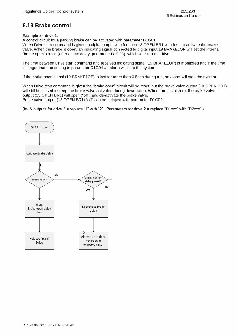
Hägglunds Spider, Control system 223/263 6 Settings and function
RE15330/2.2019, Bosch Rexroth AB
6.19 Brake control Example for drive 1: A control circuit for a parking brake can be activated with parameter D1G01. When Drive start command is given, a digital output with function 13 OPEN BR1 will close to activate the brake valve. When the brake is open, an indicating signal connected to digital input 19 BRAKE1OP will set the internal “brake open” circuit (after a time delay, parameter D1G03), which will start the drive. The time between Drive start command and received indicating signal (19 BRAKE1OP) is monitored and if the time is longer than the setting in parameter D1G04 an alarm will stop the system. If the brake open signal (19 BRAKE1OP) is lost for more than 0.5sec during run, an alarm will stop the system. When Drive stop command is given the “brake open” circuit will be reset, but the brake valve output (13 OPEN BR1) will still be closed to keep the brake valve activated during down-ramp. When ramp is at zero, the brake valve output (13 OPEN BR1) will open (“off”) and de-activate the brake valve. Brake valve output (13 OPEN BR1) “off” can be delayed with parameter D1G02. (In- & outputs for drive 2 = replace “1” with “2”. Parameters for drive 2 = replace “D1xxx” with “D2xxx”.)

Hägglunds Spider, Control system 224/263 6 Settings and function
RE15330/2.2019, Bosch Rexroth AB
6.20 Machine stop The Machine stop has a fixed input between terminal #EI/EM:1 and #EI/EM:2. The circuit consist of two parallel systems. The main system is a monitoring channel configured as Alarm. The time delay between opening of the Machine stop input and the shutdown of the electric motors is set with parameter DMD01-03. The backup system is a hardware timer on the board with possibility to set the delay between 2 and 32 sec with SW1 (see AS4.5). The timer must be set 0 - max 4seconds longer then the main system. A time set more then 4 sec longer will give a warning. If setting is shorter or 5sec longer the system will shutdown at hardware test.
Setting Time delay
0 2 sec
1 4 sec
2 6 sec
3 8 sec
4 10 sec
5 12 sec
6 14 sec
7 16 sec
8 18 sec
9 20 sec
A 22 sec
B 24 sec
C 26 sec
D 28 sec
E 30 sec
F 32 sec
At each power up and each time all electric motors are stopped, the system will check that the relays for the electric motor interlock outputs not are stucked in closed position. The check will toggle the output relays 5 times to remove oxidation from the monitoring contacts to avoid faulty errors. The Machine stop alarm is as default with memory and must be reset but can be set to automatic reset with MAB11:ON. A configurable digital input set to 09 EMSTOP can be used as Machine stop input. This only uses the main Machine stop function (software). This must be used if a ramp-down function at alarm MAB10 is configured.

Hägglunds Spider, Control system 225/263 6 Settings and function
RE15330/2.2019, Bosch Rexroth AB
6.21 Program update The program version can be updated by using the cable used for SpiderCom (576 3521-003) and the software program Loader 2_0.exe (Spider flash loader). Run Loader.exe. Select the file for download Start the procedure
Reset the Spider board by pushing the reset button or by switching on and off the power to the card to start the download procedure. When the download is ready, reset the Spider system and set new parameters. Using software from version 5.0.x requires larger memory card capacity compared to previous versions. A memory card with increased capacity was introduced in January 2007 from serial number 3395 (item number R939003962). Loading software 5.0.x to a unit with memory card before serial number 3395 will give error code “WARNING NON COMPATIBLE MEM-C” and Spider will start with default parameters.
6.22 Hardware calibration When the software is updated a hardware calibration is needed. This calibration is needed to compensate for the offset in the measuring channels for the stroker current feedback. This calibration must be done without stroker coils connected. Disconnect contact PO1, PO2, PO3 and PO4. In the main menu there is a choice for this calibration HW CALIBRATION
PWM OFFSET
CAL. OFFSET NO
CAL. OFFSET YES
will start the calibration. Calibration OK and the calibration settings will be indicated when the procedure is ready. This adjustment will be stored in an EEProm on the main board.

Hägglunds Spider, Control system 226/263 6 Settings and function
RE15330/2.2019, Bosch Rexroth AB
6.23 Flushing A motor flush function can be used in cold environment to keep the Hydraulic motor warm, see block diagram AS7.10. Digital out 11ST AUX shall be connected to control the contactor for the aux (flush) pump. In stand-by mode the aux pump will be temperature controlled. The following criterias must be fulfilled:
oil level above min
oil temperature above min setting
aux pump suction valve is open (if selected)
all used main pump suction valves are open The temperature is measured in the drain return line by a temperature sensor connected to an analog input set as DR TEMP. The switch-on temperature is set with parameter DME03 (default 5°C) and the working span by the hysteresis set with parameter DME04 (default 3°C). This means that the aux pump will switch on when the temperature falls to 5°C and switch off when the temperature reaches 8°C. When the input 19 AUX ST is activated, the aux pump will run independent of temperature. When we receive the "Flush motor running" signal on 19 FLUSH ON, the timer DME05 starts to count. After a time delay to allow the pistons to softly get in touch with the camring (default set to 300sec), the "FLUSH PUMP" signal gets high and the main pumps can be started. If the drain temperature is above the temperature level set with parameter DME07 (default set to 20°C) a shorter start delay time set by parameter DME06 is used (default 10sec). The main e-motor is not possible to start below shutdown temperature, set with parameter DME02 (default 2°C). Once the main motor is started the shutdown temperature interlock is bypassed to avoid stop when the oil temperature gets low by the rotating hydraulic motor. The flush heating valve is controlled via digital output 11 FLUSHCON. The output is activated if the signal from started aux pump is activating digital input with function 19 FLUSH ON and the tank temp is between the settings in parameters TMB14 and TMB11. Timer TMB16 is to delay valve activation after aux motor start.
Stand-by mode Flush heating Drive start

Hägglunds Spider, Control system 227/263 6 Settings and function
RE15330/2.2019, Bosch Rexroth AB
6.24 Hydraulic motor temperature monitoring Analog temp sensors can be used for monitoring and limitation of hydraulic motor temperature. It is possible to monitor 4 motors. The function has 3 limits:
warning
stroke down pump
shutdown The temperature sensor is connected to an analog input set as HMTEMP1-4. Example: Pt100/4-20mA sensor for 0-100°C on hydraulic motor 2 on Drive 1 connected to analog input 5. Warning at 50°C, stroke down at 55°C and alarm at 60°C. Connection: current input to AI2:9-10.
AIJ01 set to 4-20mA.
Set REG 405 for indication on the display.
AIJ02 and 03 shall be used to calibrate with a loop generator to show 0°C at 4mA and 100°C at 20mA on the display.
AIJ06 set to °C.
AIJ07 sets the number of decimals.
AIJ09 set to HMTEMP2 to get the limitation function.
HMA02 set to 55 for pump stroke-down temperature.
HMB02 set to Drive 1 to connect motor to right drive.
AIJ10 set 60 for alarm level
AIJ11 set 50 for warning level
AIJ12 set eg.AUX10 to give warning via Aux10 if signal is lost (see AS6.7.2 for setting example).
AIJ13 set 06 MAXTMPM2 to indicate max temperature for motor 2.
AIJ14 set 06 HITMPM2 to indicate high temperature for motor 2.
If a min speed at limitation is required this can be set with parameter D1F03.
6.25 Pulse inputs The drive can be selected for a pulse encoder input with parameter P0I0x. Drive1 is default for DE1 and Drive 2 for DE2. PxI01 parameter value must be the number of digital pulses that the speed encoder produces during one rotation. PxI06 can be changed if the rotation of the hydraulic motor/encoder is giving a wrong polarity of the reading. PxI07 determines the type of digital speed encoder used.
1. Quad. This is the standard type with two pulse trains 2. Single pulse with direction. This speed encoder gives a pulse train and in addition a directional signal
ON/OFF. 3. Single pulse without direction. This speed encoder gives one pulse train as an output.
PxI05 can be used for filtering if the reading is unstable. The setting is how long measuring and average time to have before the value of a reading is presented on the display. The reading can be scaled with PxIO4 and given an alternative reading with PxIO2. Threshold values can be set for the speed input. PxI08 sets the high level and PxI09 the low level. The function is set via AUX function for PxI10 (high) and PxI11 (low).
6.26 Compare registers. Six compare registers can be used for monitoring of combined signals. All registers in spider has a data value and a display value. This manual will describe how to use compare register 1, to configure compare register 2-6 see AS5 for parameters.

Hägglunds Spider, Control system 228/263 6 Settings and function
RE15330/2.2019, Bosch Rexroth AB
6.26.1 Data value
The data value is used for internal storage, but is used for example when calculating compare registers or for fieldbus communication. The data value is a 16bit signed integer with no decimal or unit. The full range is -32768 to 32767 but most common is to use a range of 0 to 10000 or -10000 to 10000.
6.26.2 Display value
The display value is the “real” value, including decimal and unit. The display value of REG701 is calculated from the data value by scaling data value 0 to DMG01 (min display value) and data value 10000 to DMG02 (max display value). DMG03(Unit) and DMG04 (decimal point) is also used to create the final display value.
6.26.3 Performing calculations on data values
The data value of REG701 is calculated by the operands; A: DMF01, B: DMF02, C: DMF03, K: DMF04 and the operator: DMF05. It is very important to understand that it is the data values, not the display values which are used as input during the calculations. If for example one 0-60bar and one 0-400bar pressure transmitter are to be compared they both have a data value range of 0-10000. The data value of the 60bar transmitter must be multiplied with 60/400 before the data values can be compared. See example 1. The calculation is done as a 32bit signed integer. The parameter K should only be used to keep the result in the desired data value range or to scale data values, it should not be used to scale the display value. If for example two registers (with data value range 0-10000) is multiplied by the operation A*B/K, K is most often set to 10000 to keep the result in the same range as the inputs. The compare registers are calculated in order from 1 to 6. This makes it possible to split a calculation in several steps. It is possible to first calculate REG701 and then using REG701 when calculating REG702 during the same process cycle.

Hägglunds Spider, Control system 229/263 6 Settings and function
RE15330/2.2019, Bosch Rexroth AB
6.26.4 Connecting compare register to functions
The display value can be connected to a spider function by parameter DMF06. The input will be available to the function the next process cycle.
Overview of compare register function
Input register A (DMF01)
Input register B (DMF02)
Input register C (DMF99399903)
Input constant K (DMF04)
Operator (DMF05)
Data value (most common is a range from 0 to 10000)
Data value (REG701)
Display value
(REG 701)
Min value (DMG01)
Max value (DMG02)
Unit (DMG03)
Decimals (DMG04)
Display value (actual value)
Input to analog function (DMF06)
Indication on spider display
e.g (R1B01)

Hägglunds Spider, Control system 230/263 6 Settings and function
RE15330/2.2019, Bosch Rexroth AB
Example 1: Display the torque/delta pressure of a CA100. A-port pressure transmitter: Analog input 1 ,REG401 Data value: 0-10000. Display value: 0-400bar. B-port pressure transmitter: Analog input 2, REG402. Data value: 0-10000. Display value: 0-60bar Result: Compare register 1, REG701 Data value: 0-10000. Display value: 0-40.0kNm (100Nm/bar * 400bar / 1000) Alternative display value: 0-400bar Since REG401 and REG402 have different display value ranges we need to scale the data value of REG402 with 60/400 = 1500/10000 before subtracting. Data value calculation parameters: DMF01 = REG401 Operand A, A-port pressure DMF02 = OFF Operand B, Not used DMF03 = REG402 Operand C, B-port pressure DMF04 = 1500 Operand K DMF05 = A-B-C*K/10000 Operation, Scale C, then subtract from A. DMF06 = OFF Connected function, not used Display value parameters: DMG01 = 0 Min display value DMG02 = 40 Max display value DMG03 = kNm Unit DMG04 = 1 One decimal To show the delta pressure the same data value calculation can be used. Adjust the display value parameters to: DMG01 = 0 Min display value DMG02 = 400 Max display value DMG03 = bar Unit DMG04 = 0 No decimals Note: The delta pressure will be negative if the load inertia is driving the hydraulic system in forward direction or if the hydraulic system is driving the load in reverse direction.

Hägglunds Spider, Control system 231/263 6 Settings and function
RE15330/2.2019, Bosch Rexroth AB
Example 2 Display the power on the drive shaft, CA100 The delta pressure from example 1 is used. Equation: P = T*n/9549 where, P = power in kW T = torque in Nm n = speed in rpm Delta pressure: Compare register 1, REG701 Data value: 0-10000 Display value: 0-400bar Speed: Digital speed 1, REG109 Data value: 0-10000 Display value: 0-60rpm Result: Compare register 2, REG702 Data value: 0-10000 Display value: 0-251kW (100Nm/bar*400bar*60rpm/9549) We choose K (DMF10) to 10000 keep the result data value within 0-10000 range. Data value calculation parameters: DMF07 = REG701 Operand A, torque/delta pressure DMF08 = REG109 Operand B, speed DMF09 = OFF Operand C, OFF DMF10 = 10000 Operand K DMF11 = A*B/K Operation DMF12 = OFF, Connected function, not used Display value parameters: DMG05 = 0 Min display value DMG06 = 251 Max display value DMG07 = kW Unit DMG08 = 0 No decimals Notes: Both delta pressure and speed can have negative values. If the load inertia is driving the hydraulic system the power display value will be negative. If the function EC(1-3) is set by parameter DMF12, the long term shaft power can be limited to either a fixed or a variable level.

Hägglunds Spider, Control system 232/263 6 Settings and function
RE15330/2.2019, Bosch Rexroth AB
6.27 Cooler control The cooling switch-on temperature is set with parameter TMB05. This is the temp when the cooler output will go high at increasing tank temperature. At decreasing temperature the switch-off is when the on temperature and the hysteresis TMB06 is passed. Default is 40°C for on and 37°C for off. Digital output function 11 COOLCOND is directly controlled by the temperature. Digital output function 11COOLCONI is interlocked so one electric motor must be started to activate the digital output. To keep the cooling element in the air/oil cooler clean, a controlled reversal can be done via two separate digital outputs, see block diagram AS7.4. Digital out functions 11 COOLFWD and 11 COOLREV can be used to control two separate contactors for a cooler motor. The forward time between reversals can be set with parameter TMB17. The counter will count forward time and remember the total drive time. The counter will be reset if the system is powered off. TMB18 sets the reversal time for the output. Timer TMB19 sets the stop time between forward and reverse. If parameter TMB20 is on the reversal will start by system start (main motor is started).

Hägglunds Spider, Control system 233/263 6 Settings and function
RE15330/2.2019, Bosch Rexroth AB
6.28 Drive logic The function Drive logic is used to achieve a customer specific logic relation within the Spider by simply setting up parameters. This feature allows up to four digital inputs to be combined in a Boolean expression and the result to be stored for example in a memory cell. By using this tool it is possible to control a function that depends on different parameters of the system, customer adaptation becomes easier. Drive logic is available in all variants of the Spider. See AS 5.2.14 for the parameters of Drive logic. Input selections Possible selections for parameters DLx01-04 are memory cells (MEM 01...24) or digital outputs in bus version 3 (see AS 6.15.9). Input from bus list is set by stating the corresponding addresses from the bus list, ranging from 28.0 to 71.7. The bus list is needed to be able to decode what number is corresponding to needed input function. Logical functions Three different logical functions for Drive logic can be selected in DLx05. See AS 5.2.14. AND, OR, XOR. In addition to this, three more choices are available. These choices will divide the function into two separate parts but still with the same logical function. This limits each part of the function to receive two inputs. 2xAND, 2xOR, 2xXOR Output functions Possible output functions (DLx06-09) are the same as for digital inputs, see AS 5.2.3. Depending on choice of logical function (DLx05) the result can be one output or two different outputs. For this reason it is possible to select two different functions for output (DLx06 and DLx08). The output function can also be inverted in DLx07 and DLx09. Activation of output function The output functions are activated when the logical block (DLx05) is high. It don´t matter if the function selected as output is a normally high or low signal. Example A system is equipped with four ball valves in the piping between power unit and hydraulic motor. The drive should not be started until the valves are in a correct safe position. The Ball valve indicators are connected to the digital input terminals on the Spider. Addresses for the corresponding digital inputs are selected for the Drive logic input parameters DLx01-04. Logical function “AND” is chosen in parameter DLx05. If all selected inputs for the logic block is high the output is high. Function for Output selection 1 (DLx06) is set to memory cell (MEM x). A digital output in the Spider can be configured to memory cell MEM x and will indicate when all ball valves are opened or/and used to interlock drive start if the switches are in the wrong position.

Hägglunds Spider, Control system 234/263 6 Settings and function
RE15330/2.2019, Bosch Rexroth AB
6.29 Value threshold The function Value threshold gives the possibility to threshold analog signals processed by the Spider, internal registers in Spider. On set levels this tool will trigger notifications or activities by for example output functions aux monitor or memory cell (AUX, MEM). By using compared registers (REG70x) as inputs complicated relations between different factors of the system can be handled. Value threshold is available in all functions of the Spider. See AS 5.2.15 for the parameters of Value threshold. Input registers The input parameter VTx01 is selected from the registers of drive log. See AS 5.2.26 for available registers. Threshold settings Parameters VTx02 and VTx03 are used to set high and low indication levels for the input. The level is set in the same unit as the display value of the register. For example REG102 “Speed setpoint” is displayed in percentage. A high indication level “90” will correspond to 90%. Output functions Parameters VTx04 and VTx05 are used to set functions for the high and low levels. Possible functions are the same as for digital inputs, see AS 5.2.3. Activation of output function The output functions are activated when the analog signal passes the set levels. It doesn´t matter if the function, selected as output, is a normally high or low signal. When register (VTx01) rise above high indication level (VTx02) the high output function (VTx04) is activated. When register (VTx01) falls under low indication level (VTx03) the low output function (VTx05) is activated. Example Register REG70x is set up as the difference between temperature of drain oil (out) and flush oil (in) of a hydraulic motor. This is made by using two analog temperature sensors and the Spider function Compare registers (AS 6.26). Input for Value threshold (VTx01) is set to the above calculated REG70x. High and low levels VTx02 and VTx03 are set to x and y ˚C. The functions for high and low indications VTx04 and VTx05 are set to AUX x and AUX y. By using the auxiliary monitor function (AUX) an alarm, warning or interlock indication can be trigged at the set levels. AUX x is configured as an alarm to indicate maximum temp difference over the hydraulic motor. AUX y is configured as a warning with inverted input to indicate high temp difference over the hydraulic motor. The setup will as a result create:
One Warning when the delta temperature over the hydraulic motor is above y ˚C.
One Alarm when the delta temperature over the hydraulic motor is above x ˚C.

Hägglunds Spider, Control system 235/263 6 Settings and function
RE15330/2.2019, Bosch Rexroth AB
6.30 Local interface unit The local interface card (LIC) is used in the local interface unit (LIU) for a simple and flexible placement of the front panel. The card has identical interface for displays and front panels as the main board. It will communicate with the main board via the CAN interface on CA terminals. The card has a 4-wire connection (2 signals + 24VDC supply). The maximum cable distance is 100m. The function requires card revision R3A (can be used with R2D if CAN cable is rewired).
6.30.1 Drive selection
The LIU can be used with a double display door for control/monitoring of 2 drives or with a single display door for control/monitoring of drive 1 or 2. Switch 1-1 on the LIC card selects if it is a panel for a single or double drive unit (SW1-1 on) or a Drive 2 unit (SW1-1 off). The Drive 1 and Drive 2 position can be changed with switch SW3-2 on the main board. ‘
6.30.2 Software update
The program version can be updated by using the cable used for SpiderCom (576 3521-003) and the software program Loader 2_0.exe (Spider flash loader). Note: Requires boot version 2.0. Run Loader.exe. Select the file for download Start the procedure
Reset the Spider board by pushing the reset button or by switching on and off the power to the card. This will trigger the download procedure. When the download is ready, reset the Spider system once more.

Hägglunds Spider, Control system 236/263 6 Settings and function
RE15330/2.2019, Bosch Rexroth AB
6.31 S-link Spider can be used for collection of connected sensor data in CMp system for condition monitoring. The RS232 serial port is connected to a serial port on a CCM module. Data is stored and sent cyclically via modem or Ethernet to ODiN database for storage and evaluation.
The function requires software version 5.0.3 or higher. Setup of CMp functions (spider link up/down, progress, status, signal strength, version…) is available under Spider link in Spider menu, see Parameter tree in chapter 5.1.

Hägglunds Spider, Control system 237/263 7 Block diagrams
RE15330/2.2019, Bosch Rexroth AB
7 Block diagrams 7.1 Digital in/outputs

Hägglunds Spider, Control system 238/263 7 Block diagrams
RE15330/2.2019, Bosch Rexroth AB

Hägglunds Spider, Control system 239/263 7 Block diagrams
RE15330/2.2019, Bosch Rexroth AB

Hägglunds Spider, Control system 240/263 7 Block diagrams
RE15330/2.2019, Bosch Rexroth AB
7.2 Analog in/outputs

Hägglunds Spider, Control system 241/263 7 Block diagrams
RE15330/2.2019, Bosch Rexroth AB

Hägglunds Spider, Control system 242/263 7 Block diagrams
RE15330/2.2019, Bosch Rexroth AB

Hägglunds Spider, Control system 243/263 7 Block diagrams
RE15330/2.2019, Bosch Rexroth AB
7.3 Pump outputs

Hägglunds Spider, Control system 244/263 7 Block diagrams
RE15330/2.2019, Bosch Rexroth AB
7.4 Monitor

Hägglunds Spider, Control system 245/263 7 Block diagrams
RE15330/2.2019, Bosch Rexroth AB

Hägglunds Spider, Control system 246/263 7 Block diagrams
RE15330/2.2019, Bosch Rexroth AB

Hägglunds Spider, Control system 247/263 7 Block diagrams
RE15330/2.2019, Bosch Rexroth AB

Hägglunds Spider, Control system 248/263 7 Block diagrams
RE15330/2.2019, Bosch Rexroth AB

Hägglunds Spider, Control system 249/263 7 Block diagrams
RE15330/2.2019, Bosch Rexroth AB

Hägglunds Spider, Control system 250/263 7 Block diagrams
RE15330/2.2019, Bosch Rexroth AB
7.5 Basic function

Hägglunds Spider, Control system 251/263 7 Block diagrams
RE15330/2.2019, Bosch Rexroth AB

Hägglunds Spider, Control system 252/263 7 Block diagrams
RE15330/2.2019, Bosch Rexroth AB
7.6 Shredder function

Hägglunds Spider, Control system 253/263 7 Block diagrams
RE15330/2.2019, Bosch Rexroth AB

Hägglunds Spider, Control system 254/263 7 Block diagrams
RE15330/2.2019, Bosch Rexroth AB
7.7 Synchro function

Hägglunds Spider, Control system 255/263 7 Block diagrams
RE15330/2.2019, Bosch Rexroth AB

Hägglunds Spider, Control system 256/263 7 Block diagrams
RE15330/2.2019, Bosch Rexroth AB
7.8 Pressure Function

Hägglunds Spider, Control system 257/263 7 Block diagrams
RE15330/2.2019, Bosch Rexroth AB
7.9 Machine stop

Hägglunds Spider, Control system 258/263 7 Block diagrams
RE15330/2.2019, Bosch Rexroth AB
7.10 Flush control

Hägglunds Spider, Control system 259/263 7 Block diagrams
RE15330/2.2019, Bosch Rexroth AB
7.11 Compare registers

Hägglunds Spider, Control system 260/263 7 Block diagrams
RE15330/2.2019, Bosch Rexroth AB
7.12 Drive logic

Hägglunds Spider, Control system 261/263 7 Block diagrams
RE15330/2.2019, Bosch Rexroth AB
7.13 Threshold function

Hägglunds Spider, Control system 262/263 Declaration of conformity
RE15330/2.2019, Bosch Rexroth AB
8 Declaration of conformity

Hägglunds Spider, Control system 263/263 Notes
RE15330/2.2019, Bosch Rexroth AB
Notes