Embed Size (px)
Citation preview
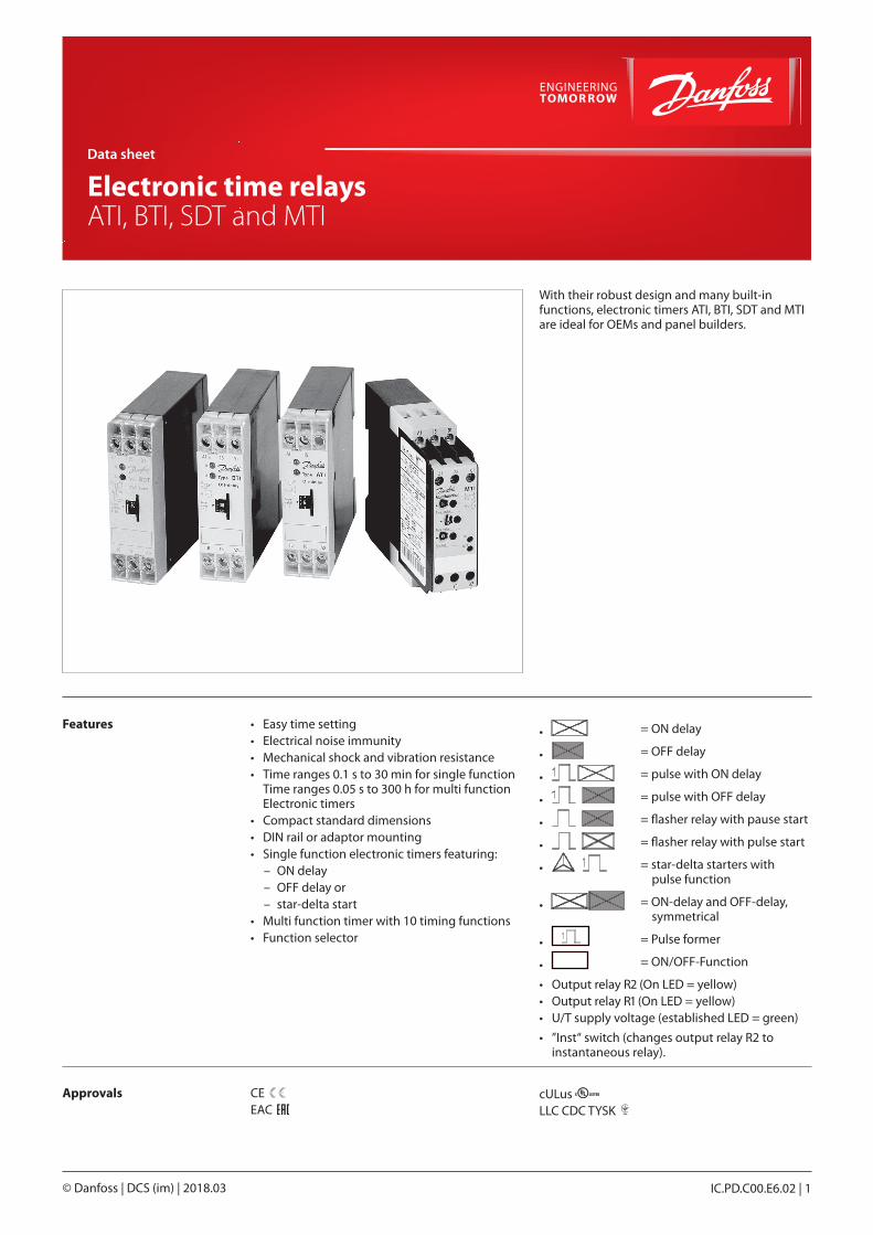
Data sheet
Electronic time relays ATI, BTI, SDT and MTI
IC.PD.C00.E6.02 | 1© Danfoss | DCS (im) | 2018.03
With their robust design and many built-in functions, electronic timers ATI, BTI, SDT and MTI are ideal for OEMs and panel builders.
Features
Approvals
• Easy time setting• Electrical noise immunity• Mechanical shock and vibration resistance• Time ranges 0.1 s to 30 min for single function
Time ranges 0.05 s to 300 h for multi function Electronic timers
• Compact standard dimensions• DIN rail or adaptor mounting• Single function electronic timers featuring:
– ON delay – OFF delay or – star-delta start
• Multi function timer with 10 timing functions• Function selector
• = ON delay
• = OFF delay
• = pulse with ON delay
• = pulse with OFF delay
• = flasher relay with pause start
• = flasher relay with pulse start
• = star-delta starters with pulse function
• = ON-delay and OFF-delay, symmetrical
• = Pulse former
• = ON/OFF-Function
• Output relay R2 (On LED = yellow)• Output relay R1 (On LED = yellow)• U/T supply voltage (established LED = green)
• ”Inst“ switch (changes output relay R2 to instantaneous relay).
CEEAC
cULus LLC CDC TYSK 089

Data sheet | Electronic time relays ATI, BTI, SDT and MTI
© Danfoss | DCS (im) | 2018.032 | IC.PD.C00.E6.02
Ordering ON-delay electronic timers
Type Time range Voltage range Contact function Code no.
ATI
0.1 – 10 s
220 – 240 V AC, 50 – 60 Hz
1 changeover
047H309224 V AC, 50 – 60 Hz
24 V DC
0.3 – 30 s
220 – 240 V AC, 50 – 60 Hz
047H310424 V AC, 50 – 60 Hz
24 V DC
3 – 300 s
220 – 240 V AC, 50 – 60 Hz
047H309324 V AC, 50 – 60 Hz
24 V DC
0.3 – 30 min.
220 – 240 V AC, 50 – 60 Hz
047H310524 V AC, 50 – 60 Hz
24 V DC
OFF-delay electronic timers
Type Time range Voltage range Contact function Code no.
BTI
3 – 300 s24 V AC, 50 – 60 Hz
1 changeover
047H309524 V DC
0.3 – 30 s 220 – 240 V AC, 50 – 60 Hz 047H3107
3 – 300 s 220 – 240 V AC, 50 – 60 Hz 047H3099
Star-delta electronic timers
Type Time range Voltage range Contact function Code no.
SDT 0.3 – 30 s
110 – 130 V AC, 50 – 60 Hz
1 changeover
047H3110
220 – 240 V AC, 50 – 60 Hz
047H311124 V AC, 50 – 60 Hz
24 V DC
380 – 415 V AC, 50 – 60 Hz 047H3112
Multi function electronic timers
Type Time range Voltage range Contact fuction Code no.
MTI 0.05 s – 300 h24 – 240 V AC, 50 – 60 Hz
2 changeover 047H307724 – 48 V DC

Data sheet | Electronic time relays ATI, BTI, SDT and MTI
© Danfoss | DCS (im) | 2018.03 IC.PD.C00.E6.02 | 3
Technical data Type designation ATI BTI SDT MTIOutput circuit
Changeover switch 1 1 1 2Max. A on 250 V 4 4 4 4AC-15 on 230 V (A) 1.5 1.5 1.5 3AC-15 on 415 V (A) 0.25DC-12 on 24 V (A) 4 4 4 4DC-13 on 24 V (A) 2 2 2 2
Input
Supply voltage
AC/DC 24 V •DC 24 – 48 V AC 24 – 240 V •AC/DC 24 V AC 220 – 240 V • •AC 110 – 130 V • •AC 220 – 240 V •AC 380 – 415 V •
Voltage tolerance -10% – 10% -15% – 10%Frequency 50 – 60 HzDuty rating Continuous
ConsumptionAC/DC 24 V 1.0 VA / WAC 220 – 240 V 12.0 VAAC 380 – 415 V 23.0 VA
Time circuit
Time ranges
0.1 – 10 s 0.3 – 30s0.3 – 30 s 0.15 – 3 s 0.05 – 1 s 1.5 – 30 s 1.5 – 30 min.
3 – 300 s 5 – 100 s 5 – 100 s 1.5 – 300 min.
0.3 – 30 min. 0.5 – 10 s 15 – 300 s 1.5 – 30 min.
10 time ranges in each unit 15 – 300 hReset time (dwell time) < 100 ms 400 ms 80 msControl pulse time > 20 msY/D changeover time 30 ms 50 msRepeat accuracy < 1% 0.2%Time deviation within voltage tolerance < 0.5% 0.004% / VTime deviation within temperature range < 0.1% / °C 0.03% / °C
Ambient temperature
operation -20 °C – 60 °C -25 °C – 60 °Cstorage -40 °C – 80 °C -40 °C – 85 °C
Control contact Y1 – Z2No-load voltage 10 – 40 V DC
Remote pot.meter connection Z1 Cable screen Z2 to screen
Potentiometer resistance 50 KΩ 2 x 25 m shielded with 100 pF/m
LED indicationSupply voltage, green • • • •Supply voltage, green/flashes when timg •Output relay R1, yellow •Outout relay R2, yellow •
Other dataInstallation DIN railEnclosure, housing/terminals IP50 / IP20Installation orientation AnyMechanical life 30 x 106
Electrical life, ohmic load 100,000 operations on 8 A, 230 V AC 100,000 operations on 4 A, 230 V ACMax. fuse 2 A, gl 6 A, glMax. lead cross-section 2 × 1.5 mm2 2 × 2.5 mm2
Test voltage 2.5 kV, 50 Hz, 1 s 2.0 kV, 50 Hz, 1 sEMC Directive 2004 / 108 / EC

Data sheet | Electronic time relays ATI, BTI, SDT and MTI
© Danfoss | DCS (im) | 2018.034 | IC.PD.C00.E6.02
Load graphs, electronic time relays ATI, BTI, SDT, MTI
Reduction factor F for inductive load on timers
Electrical life (N), AC-1 load
DC load (DC-1)
Approvalauthority
089
Product typeEN 60947 EAC
UL-listed CANADA
USA
LLC CDC TYSK
ATI / BTI / SDT
MTI
• Approved
Approvals
Data sheet | Electronic time relays ATI, BTI, SDT and MTI
© Danfoss | DCS (im) | 2018.03 IC.PD.C00.E6.02 | 5
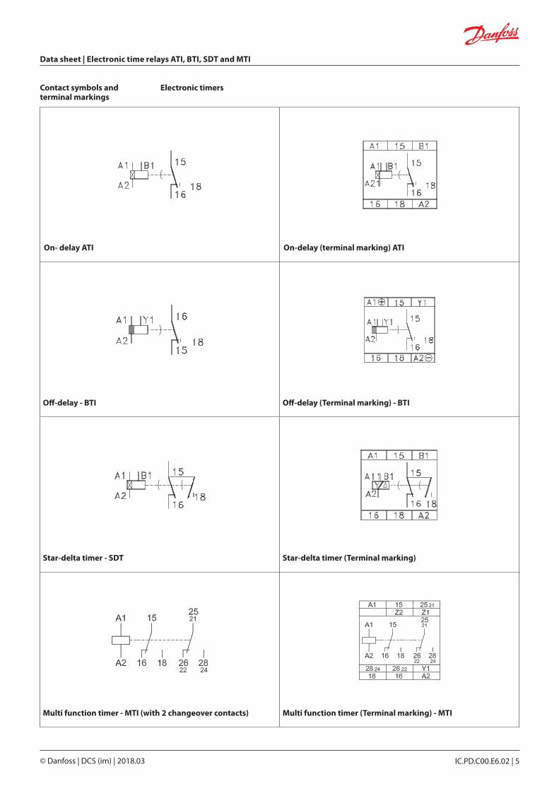
Contact symbols and terminal markings
On- delay ATI On-delay (terminal marking) ATI
Off-delay - BTI Off-delay (Terminal marking) - BTI
Star-delta timer - SDT Star-delta timer (Terminal marking)
Multi function timer - MTI (with 2 changeover contacts) Multi function timer (Terminal marking) - MTI
Electronic timers

Data sheet | Electronic time relays ATI, BTI, SDT and MTI
© Danfoss | DCS (im) | 2018.036 | IC.PD.C00.E6.02
Function overview, electronic time relays
ON delayWhen voltage is applied to A1/A2 the time interval begins.When the time interval elapses, the output relay is energised and remains energised until the voltage supply is cut off.With 24 V supply, terminals A1 and B1 must be used.
OFF delayThe supply must be connected to A1/A2 and remain established. Time interval start is controlled by a contact on terminal Y1.When the contact is made, the output relay is energised. When the con-tact is broken, the time interval starts (control pulse length min. 20 ms).When the set time interval elapses, the output relay drops back to its dwell position. If the control contact for terminal Y1 makes during the time interval, the interval is stopped. If the contact is broken again, the time interval starts anew.Note! External load must not be connected so that it is supplied via control contact Y1.
Star-delta relayWhen voltage is applied to A1/A2 the time interval starts.When the time interval elapses, the output relay energises. The Y-contactor switch-off and after a dwell time of 30 – 35 ms the D contactor switch-in.With 24 V supply, terminals A1 and B1 must be used.
n supply on and contact made t set time
n supply on and contact made t set time
n supply on and contact made t1 set time (Y-operation) t2changeover pause (approx. 30 ms)
Data sheet | Electronic time relays ATI, BTI, SDT and MTI
© Danfoss | DCS (im) | 2018.03 IC.PD.C00.E6.02 | 7
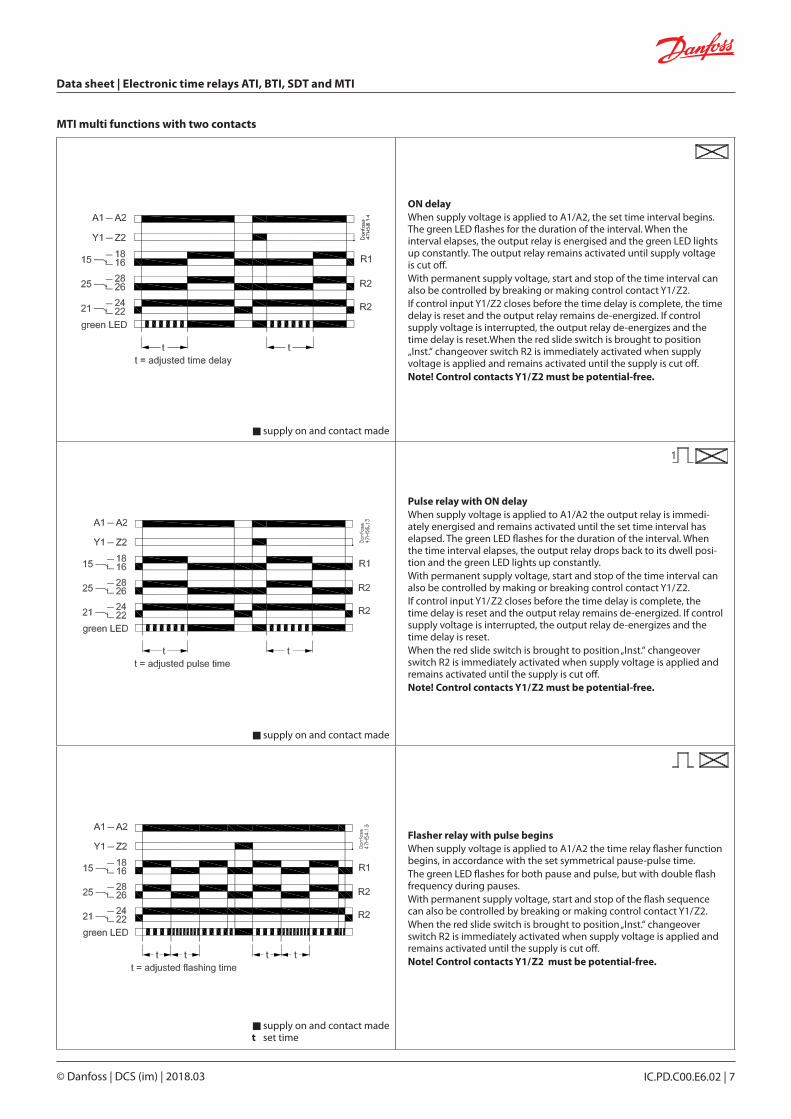
ON delayWhen supply voltage is applied to A1/A2, the set time interval begins. The green LED flashes for the duration of the interval. When the interval elapses, the output relay is energised and the green LED lights up constantly. The output relay remains activated until supply voltage is cut off.With permanent supply voltage, start and stop of the time interval can also be controlled by breaking or making control contact Y1/Z2.If control input Y1/Z2 closes before the time delay is complete, the time delay is reset and the output relay remains de-energized. If control supply voltage is interrupted, the output relay de-energizes and the time delay is reset.When the red slide switch is brought to position „Inst.“ changeover switch R2 is immediately activated when supply voltage is applied and remains activated until the supply is cut off.Note! Control contacts Y1/Z2 must be potential-free.
Pulse relay with ON delayWhen supply voltage is applied to A1/A2 the output relay is immedi-ately energised and remains activated until the set time interval has elapsed. The green LED flashes for the duration of the interval. When the time interval elapses, the output relay drops back to its dwell posi-tion and the green LED lights up constantly.With permanent supply voltage, start and stop of the time interval can also be controlled by making or breaking control contact Y1/Z2.If control input Y1/Z2 closes before the time delay is complete, the time delay is reset and the output relay remains de-energized. If control supply voltage is interrupted, the output relay de-energizes and the time delay is reset.When the red slide switch is brought to position „Inst.“ changeover switch R2 is immediately activated when supply voltage is applied and remains activated until the supply is cut off.Note! Control contacts Y1/Z2 must be potential-free.
Flasher relay with pulse beginsWhen supply voltage is applied to A1/A2 the time relay flasher function begins, in accordance with the set symmetrical pause-pulse time.The green LED flashes for both pause and pulse, but with double flash frequency during pauses.With permanent supply voltage, start and stop of the flash sequence can also be controlled by breaking or making control contact Y1/Z2.When the red slide switch is brought to position „Inst.“ changeover switch R2 is immediately activated when supply voltage is applied and remains activated until the supply is cut off.Note! Control contacts Y1/Z2 must be potential-free.
n supply on and contact made
n supply on and contact made
n supply on and contact made t set time
MTI multi functions with two contacts
Data sheet | Electronic time relays ATI, BTI, SDT and MTI
© Danfoss | DCS (im) | 2018.038 | IC.PD.C00.E6.02
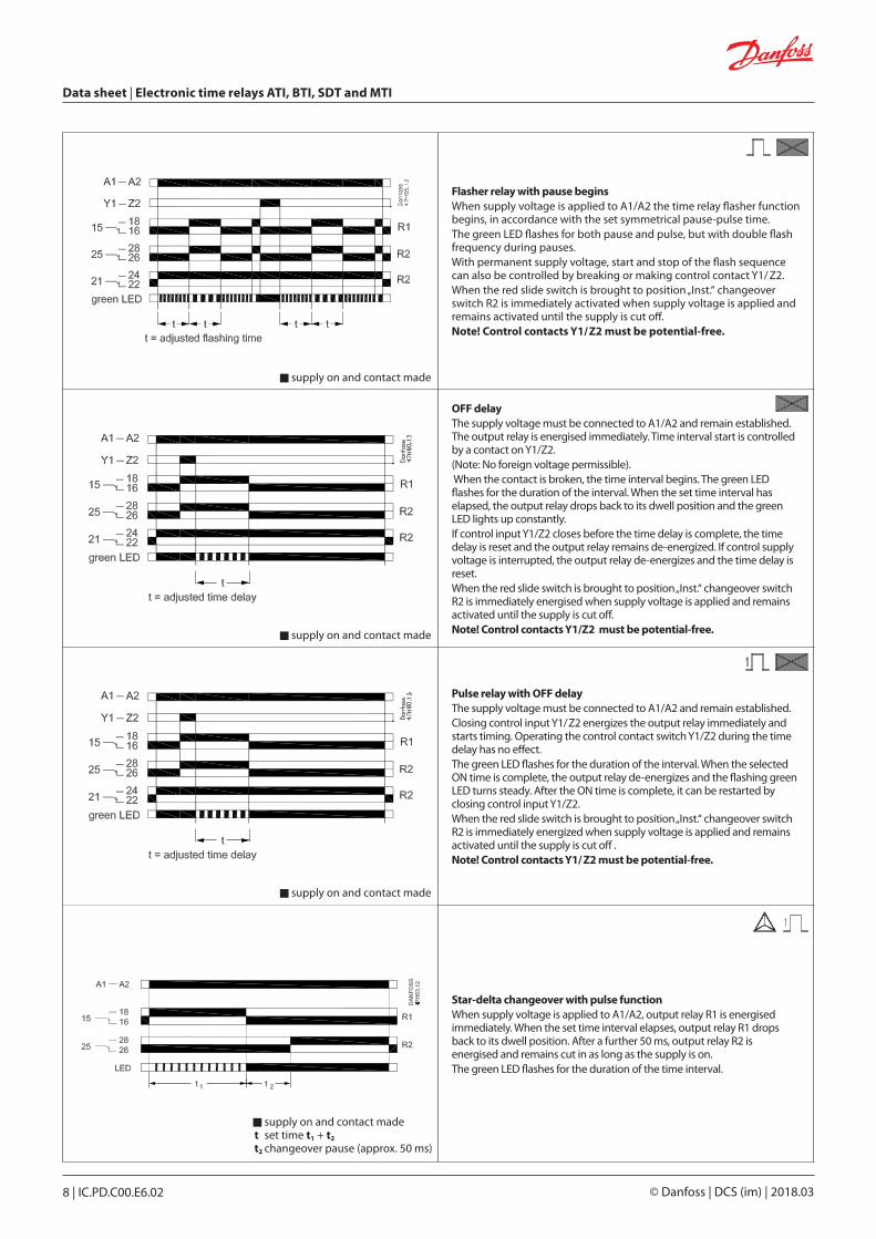
Flasher relay with pause begins When supply voltage is applied to A1/A2 the time relay flasher function begins, in accordance with the set symmetrical pause-pulse time.The green LED flashes for both pause and pulse, but with double flash frequency during pauses.With permanent supply voltage, start and stop of the flash sequence can also be controlled by breaking or making control contact Y1/ Z2.When the red slide switch is brought to position „Inst.“ changeover switch R2 is immediately activated when supply voltage is applied and remains activated until the supply is cut off.Note! Control contacts Y1/Z2 must be potential-free.
OFF delayThe supply voltage must be connected to A1/A2 and remain established. The output relay is energised immediately. Time interval start is controlled by a contact on Y1/Z2. (Note: No foreign voltage permissible). When the contact is broken, the time interval begins. The green LED flashes for the duration of the interval. When the set time interval has elapsed, the output relay drops back to its dwell position and the green LED lights up constantly.If control input Y1/Z2 closes before the time delay is complete, the time delay is reset and the output relay remains de-energized. If control supply voltage is interrupted, the output relay de-energizes and the time delay is reset.When the red slide switch is brought to position „Inst.“ changeover switch R2 is immediately energised when supply voltage is applied and remains activated until the supply is cut off.Note! Control contacts Y1/Z2 must be potential-free.
Pulse relay with OFF delayThe supply voltage must be connected to A1/A2 and remain established. Closing control input Y1/Z2 energizes the output relay immediately and starts timing. Operating the control contact switch Y1/Z2 during the time delay has no effect.The green LED flashes for the duration of the interval. When the selected ON time is complete, the output relay de-energizes and the flashing green LED turns steady. After the ON time is complete, it can be restarted by closing control input Y1/Z2.When the red slide switch is brought to position „Inst.“ changeover switch R2 is immediately energized when supply voltage is applied and remains activated until the supply is cut off .Note! Control contacts Y1/Z2 must be potential-free.
Star-delta changeover with pulse functionWhen supply voltage is applied to A1/A2, output relay R1 is energised immediately. When the set time interval elapses, output relay R1 drops back to its dwell position. After a further 50 ms, output relay R2 is energised and remains cut in as long as the supply is on.The green LED flashes for the duration of the time interval.
n supply on and contact made
n supply on and contact made
n supply on and contact made
n supply on and contact made t set time t1 + t2 t2 changeover pause (approx. 50 ms)

Data sheet | Electronic time relays ATI, BTI, SDT and MTI
© Danfoss | DCS (im) | 2018.03 IC.PD.C00.E6.02 | 9
n supply on and contact made
n supply on and contact made
n supply on and contact made
Symmetrical ON and OFF-delayThe supply voltage must be connected to A1/A2 and remain established. Time interval start is controlled by a contact on Y1/Z2. Closing control input Y1/Z2 starts the ON-delay t1. When timing is complete, the output relay energizes. Opening control input Y1/Z2 starts the OFF-delay t2. Both timing functions are displayed by the flashing green LED. When the OFF-delay t2 is complete, the output relay de-energizes.If control input Y1/Z2 opens before the ON-delay t1 is complete, the time delay is reset and the output relay remains de-energized. If control input Y1/Z2 closes before the OFF-delay t2 is complete, the time delay is reset and the output relay remains energized.When the red slide switch is brought to position „Inst.“ changeover switch R2 is immediately energized when supply voltage is applied and remains activated until the supply is cut off .Note! Control contacts Y1/Z2 must be potential-free.
Pulse formerThe supply voltage must be connected to A1/A2 and remain established. Closing control input Y1/Z2 energizes the output relay immediately and starts timing. Operating the control contact switch Y1/Z2 during the time delay has no effect.The green LED flashes for the duration of the interval. When the selected ON time is complete, the output relay de-energizes and the flashing green LED turns steady. After the ON time is complete, it can be restarted by closing control input Y1/Z2.When the red slide switch is brought to position „Inst.“ changeover switch R2 is immediately energized when supply voltage is applied and remains activated until the supply is cut off .Note! Control contacts Y1/Z2 must be potential-free.
ON/OFF-functionThis function is used for test purposes during commissioning and trouble-shooting.If the selected max. value of the time range is smaller than 300 h (front-face potentiometer “Time sector” not 300 h), applying control supply voltage energizes the output relay immediately and the green LED glows.Interrupting control supply voltage, de-energizes the output relay. If the selected max. value of the time range is 300 h (front-face potentiometer “Time sector” = 300 h) and control supply voltage is applied, the green LED glows, but the output relay does not energize.Time settings and operating of the control inputs have no effect on the operation.
© Danfoss | DCS (im) | 2018.03 IC.PD.C00.E6.02 | 10
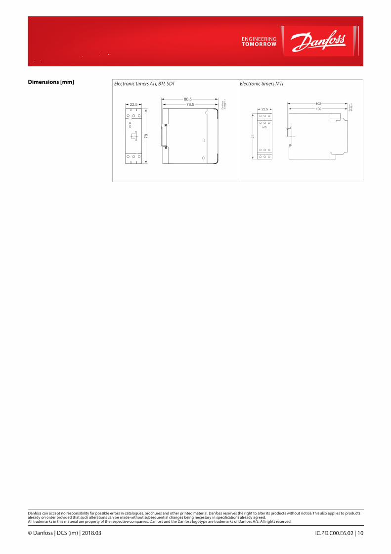
Electronic timers ATI, BTI, SDT Electronic timers MTIDimensions [mm]