Embed Size (px)
Citation preview

© Danfoss | 2017.01 VD.CC.X7.02 | 1
Differential pressure and flow controller (PN 25)AVPQ – return mounting, adjustable settingAVPQ 4 – flow mounting, adjustable setting
Data sheet
Description
AVPQ
AVPQ 4
AVPQ Controller (return mounting)
Picture DN(mm)
kVS(m3/h) Connection
Δp setting range
(bar)Code No.
Δp setting range
(bar)Code No.
15
0.4
Cylindr.ext.
threadacc. to
ISO 228/1
G ¾ A
0.2-1.0
003H6918
0.3-2.0
003H6920
1.0 003H6919 003H6921
1.6 003H6531 003H6539
2.5 003H6532 003H6540
4.0 003H6533 003H6541
20 6.3 G 1 A 003H6534 003H6542
25 8.0 G 1¼ A 003H6535 003H6543
32 12.5 G 1¾ A 003H6536 003H6544
40 16 G 2 A 003H6537 003H6545
50 20 G 2½ A 003H6538 003H6546
32 12.5Flanges PN 25,
acc. to EN 1092-2
003H6563 003H6566
40 20 003H6564 003H6567
50 25 003H6565 003H6568
Ordering
Example:Differential pressure and flow controller; return mounting;DN 15; kVS 1.6; PN 25; setting range 0.2-1.0 bar; Tmax 150 °C; ext. thread
- 1× AVPQ DN 15 controller Code No: 003H6531- 1× Impulse tube set AV, R 1⁄8 Code No: 003H6852
Option:- 1× Weld-on tailpieces Code No: 003H6908
The controller will be delivered completely assembled, inclusive impulse tube(s) between valve and actuator. External impulse tube (AV) must be ordered separately.
AVPQ(4) is a self-acting differential pressure and flow controller primarily for use in district heating systems. The controller closes on rising differential pressure or when set max. flow is exceeded.
The controller has a control valve with adjustable flow restrictor, an actuator with two control diaphragms and handle for differential pressure setting.
Main data:• DN 15-50• kVS 0.4-25 m3/h• Flow range: 0.015-15 m3/h• PN 25• Setting range: 0.2-1.0 bar/0.3-2.0 bar• Flow restrictor ∆pb: 0.2 bar• Temperature: Circ. water / glycolic water up to 30% : 2 … 150 °C• Connections:
- Ext. thread (weld-on, ext. thread and flange tailpieces)
- Flange

Data sheet Differential pressure and flow controller AVPQ (4) (PN 25)
2 | © Danfoss | 2017.01 VD.CC.X7.02
Ordering (continuous) AVPQ 4 Controller (flow mounting)
Picture DN(mm)
kVS(m3/h) Connection
Δp setting range
(bar)Code No.
Δp setting range
(bar)Code No.
15
0.4
Cylindr.ext.
threadacc. to
ISO 228/1
G ¾ A
0.2-1.0
003H6922
0.3-2.0
003H6924
1.0 003H6923 003H6925
1.6 003H6547 003H6555
2.5 003H6548 003H6556
4.0 003H6549 003H6557
20 6.3 G 1 A 003H6550 003H6558
25 8.0 G 1¼ A 003H6551 003H6559
32 12.5 G 1¾ A 003H6552 003H6560
40 16 G 2 A 003H6553 003H6561
50 20 G 2½ A 003H6554 003H6562
32 12.5Flanges PN 25, acc.
to EN 1092-2
003H6569 003H6572
40 20 003H6570 003H6573
50 25 003H6571 003H6574
Accessories Picture Type designation DN Connection Code No.
Weld-on tailpieces
15
-
003H6908
20 003H6909
25 003H6910
32 003H6911
40 003H6912
50 003H6913
External thread tailpieces
15
Conical ext. thread acc. to EN 10226-1
R ½ 003H6902
20 R ¾ 003H6903
25 R 1 003H6904
32 R 1¼ 003H6905
40 R 1½ 065B2004
50 R 2 065B2005
Flange tailpieces
15
Flanges PN 25, acc. to EN 1092-2
003H6915
20 003H6916
25 003H6917
Impulse tube set AV
Description:- 1x copper tube Ø6 × 1 × 1500 mm- 1x compression fitting 1) for imp. tube connection to pipe Ø6 × 1 mm
R 1⁄8 003H6852
R 3⁄8 003H6853
R ½ 003H68541) 10 compression fittings for imp. tube connection to pipe, Ø6 × 1 mm R 1⁄8 003H68571) 10 compression fittings for imp. tube connection to pipe, Ø6 × 1 mm R 3⁄8 003H68581) 10 compression fittings for imp. tube connection to pipe, Ø6 × 1 mm R ½ 003H68591) 10 compression fittings for imp. tube connection to actuator, Ø6 × 1 mm G 1⁄8 003H6931
Shut off valve Ø6 mm 003H0276
1) Compression fitting consists of a nipple, compression ring and nut.

Data sheet Differential pressure and flow controller AVPQ (4) (PN 25)
© Danfoss | 2017.01 | 3VD.CC.X7.02
ValveNominal diameter DN 15 20 25 32 40 50
kVS value
m3/h
0.4 1.0 1.6 2.5 4.0 6.3 8.0 12.5 16/20 4) 20/25 4)
Range of max.flow setting ∆pb 1) = 0.2 bar
from 0.015 0.02 0.03 0.07 0.07 0.16 0.2 0.4 0.8 0.8
to 0.18 0.4 0.86 1.4 2.2 3.0 3.5 8.0 10 12
or to 3) - - 0.9 1.6 2.4 3.5 4.5 10 12 15
Cavitation factor z ≥ 0.6 ≥ 0.55 ≥ 0.5
Leakage acc. to standard IEC 534 % of kVS ≤ 0.02 ≤ 0.05
Nominal pressure PN 25
Min. differential pressurebar
see remark 2)
Max. differential pressure 20 16
Medium Circulation water / glycolic water up to 30%
Medium pH Min. 7, max. 10
Medium temperature °C 2 … 150
Connections
valve External thread Ext. thread and flange
tailpiecesWeld-on and external thread
Flange -
Materials
Valve bodythread Red bronze CuSn5ZnPb (Rg5) Ductile iron
EN-GJS-400-18-LT (GGG 40.3)flange -
Valve seat Stainless steel, mat. No. 1.4571
Valve cone Dezincing free brass CuZn36Pb2As
Sealing EPDM
Pressure relieve system Piston
1) ∆pb - differential pressure over flow restrictor
2) Depends on the flow rate and valve kVS ; For Qset = Qmax -> ∆pmin ≥ 0.5 bar; For Qset < Qmax -> b
2
VSmin p
kQ
p
3) Higher max flow are achieved at higher differential pressures over AVPQ(4) controller. In general at Δp > 1-1.5 bar4) Flange valve body
Technical data
Picture Type designation ∆p setting range (bar)
Code No.
AVPQ AVPQ 4
Actuator with adjustable handle
0.2-1.0 003H6833 003H6838
0.3-2.0 003H6850 003H6851
Ordering (continuous) Service kits
Picture Type designation DN kVS
(m3/h) Code No.
Valve insert
15
0.4 003H6861
1.0 003H6862
1.6 003H6863
2.5 003H6864
4.0 003H6865
20 6.3 003H6866
25 8.0 003H6867
32 / 40 / 50 12.5 / 16 / 20 / 25 003H6868

Data sheet Differential pressure and flow controller AVPQ (4) (PN 25)
4 | © Danfoss | 2017.01 VD.CC.X7.02
Installation positions Up to medium temperature of 100 °C the controllers can be installed in any position.
For higher temperatures the controllers have to be installed in horizontal pipes only, with a pressure actuator oriented downwards.
Direct-connected heating system Indirectly connected heating system
Application principles- Return mounting
Direct-connected heating system Indirectly connected heating system
- Flow mounting
Technical data (continuous) ActuatorType AVPQ AVPQ 4
Actuator size cm2 54
Nominal pressure PN 25
Flow restrictor diff. pressure, ∆pb bar 0.2
Diff. pressure setting ranges andspring colours bar
0.2-1.0 0.3-2.0 0.2-1.0 0.3-2.0
yellow red yellow red
Materials
HousingUpper casing of actuator Stainless steel, mat. No.1.4301
Lower casing of actuator Dezincing free brass CuZn36Pb2As
Diaphragm EPDM
Impulse tube Copper tube Ø6 × 1 mm

Data sheet Differential pressure and flow controller AVPQ (4) (PN 25)
© Danfoss | 2017.01 | 5VD.CC.X7.02
DN 15 kVS 1.6
DN 15 kVS 2.5DN 15 kVS 4.0
DN 50 kVS 20, 25DN 40 kVS 16, 20
DN 32 kVS 12.5
DN 20 kVS 6.3DN 25 kVS 8.0
1 = 360 º
DN 15 kVS 1.0
DN 15 kVS 0.4
EN-GJS-400-18-LT (GGG 40.3) PN 25CuSn5ZnPb (Rg5) PN 25
Flow diagram Sizing and setting diagramRelation between actual flow and number of revolutions on flow restictor. Values given are approximate.
Flow can be adjusted by turning flow restrictor screw counter-clockwise as shown in this diagram.Water flow shown at differential pressure across flow
restrictor 0.2 bar (20 kPa) and across the controller from 0.5 bar (50 kPa) to 16/20 bar (1600/2000 kPa).
Remark:Controllers DN 40 and DN 50 have the same curve up to 9 revolutions.
Pressure temperature diagram
Maximum allowed operating pressure as a function of medium temperature (according to EN 1092-2 and EN 1092-3).
Note:For max flow setting on the controller diagrams from Instructions should be used.

Data sheet Differential pressure and flow controller AVPQ (4) (PN 25)
6 | © Danfoss | 2017.01 VD.CC.X7.02
Qmax
Δpmin Δpcircuit
Δpb
ΔpAVPQ
AVPQ
ΔpMCV
Qmax
Δpmin Δpcircuit
Δpb
ΔpAVPQ
AVPQ 4
ΔpMCV
The total pressure loss across the controller is: ∆pAVPQ = ∆pmin − ∆pMCV = 0.9 – 0.3 ∆pAVPQ = 0.6 bar (60 kPa)
Possible pipe pressure losses in tubes, shut-off fittings, heatmeters, etc. are not included.
kv value is calculated according to formula:
2.06.0
9.1
pp
Qk
bAVPQ
maxv
kv = 3.0 m3/h
Solution:The example selects AVPQ(4) DN 15, kVS value 4.0, with differential pressure setting range 0.2-1.0 bar, flow setting range 0.07-2.4 m3/h.
Sizing
- Directly connected heating system
Example 1Motorised control valve (MCV) for mixing circuit in direct-connected heating system requires differential pressure of 0.3 bar (30 kPa) and flow less than 1900 l/h.
Given data:Qmax = 1.9 m3/h (1900 l/h)∆pmin = 0.9 bar (90 kPa)∆pcircuit 1) = 0.1 bar (10 kPa) ∆pMCV = 0.3 bar (30 kPa) selected∆pb 2) = 0.2 bar (20 kPa)Remark:1) ∆pcircuit corresponds to the required pump pressure in the
heating circuit and is not to be considered when sizing the AVPQ(4).
2) ∆pb is differential pressure over flow restrictor.
The differential pressure set value is:∆pset value = ∆pMCV∆pset value = 0.3 bar (30 kPa)

Data sheet Differential pressure and flow controller AVPQ (4) (PN 25)
© Danfoss | 2017.01 | 7VD.CC.X7.02
Qmax
ΔpminΔpexchanger
Δpb
ΔpAVPQ
AVPQ
ΔpMCV
Qmax
ΔpminΔpexchanger
Δpb
ΔpAVPQ
AVPQ 4
ΔpMCV
The total pressure loss across the controller is:∆pAVPQ = ∆pmin − ∆pexchanger − ∆pMCV∆pAVPQ = 1.0 − 0.05 − 0.3 ∆pAVPQ = 0.65 bar (65 kPa)
Possible pipe pressure losses in tubes, shut-off fittings, heatmeters, etc. are not included.
kv value is calculated according to formula:
2.065.0
15.1
pp
Qk
bAVPQ
maxv
kv = 1.7 m3/h
Solution:The example selects AVPQ(4) DN 15, kVS value 2.5, with differential pressure setting range 0.2-1.0 bar, flow setting range 0.07-1.6 m3/h.
Example 2Motorised control valve (MCV) for indirectly connected heating system requires differential pressure of 0.3 (30 kPa) bar and flow less than 1150 l/h.
Given data:Qmax = 1.15 m3/h (1150 l/h)∆pmin = 1.0 bar (100 kPa)∆pexchanger = 0.05 bar (5 kPa)∆pMCV = 0.3 bar (30 kPa) selected∆pb 1) = 0.2 bar (20 kPa)Remark:1) ∆pb is differential pressure over flow restrictor
The differential pressure set value is:∆pset value = ∆pexchanger + ∆pMCV∆pset value = 0.05 + 0.3 ∆pset value = 0.35 bar (35 kPa)
Sizing (continuous)
- Indirectly connected heating system

Data sheet Differential pressure and flow controller AVPQ (4) (PN 25)
8 | © Danfoss | 2017.01 VD.CC.X7.02
AVPQ (0.2-1.0 bar) - return mounting
AVPQ (0.3-2.0 bar) - return mounting
AVPQ 4 - flow mounting
Design
1. Cover 2. Adjustable flow restrictor 3. Valve body 4. Valve insert 5. Pressure relieved valve cone 6. Valve stem 7. Control drain 8. Control diaphragm for flow
control 9. Control diaphragm for diff.
pressure control 10. Setting spring for diff.
pressure control 11. Handle for diff. pressure
setting, prepared for sealing 12. Adjuster for diff. pressure
setting, prepared for sealing 13. Union nut 14. Compression fitting for
impulse tube 15. Upper casing of actuator16. Lower casing of actuator 17. Impulse tube18. Excess pressure safety valve19. Actuator
Data sheet Differential pressure and flow controller AVPQ (4) (PN 25)
© Danfoss | 2017.01 | 9VD.CC.X7.02
l ll lll llll lllll
0,2 0,4 0,6 0,8 1,0 bar 20 40 60 80 100 kPa
l ll lll llll lllll
0,3 0,73 1,16 1,58 2,0 bar 30 73 116 158 200 kPa
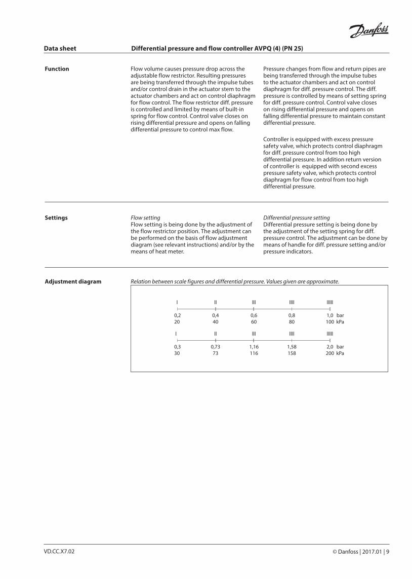
Flow volume causes pressure drop across the adjustable flow restrictor. Resulting pressures are being transferred through the impulse tubes and/or control drain in the actuator stem to the actuator chambers and act on control diaphragm for flow control. The flow restrictor diff. pressure is controlled and limited by means of built-in spring for flow control. Control valve closes on rising differential pressure and opens on falling differential pressure to control max flow.
Pressure changes from flow and return pipes are being transferred through the impulse tubesto the actuator chambers and act on controldiaphragm for diff. pressure control. The diff.pressure is controlled by means of setting spring for diff. pressure control. Control valve closes on rising differential pressure and opens on falling differential pressure to maintain constant differential pressure.
Controller is equipped with excess pressure safety valve, which protects control diaphragm for diff. pressure control from too high differential pressure. In addition return version of controller is equipped with second excess pressure safety valve, which protects control diaphragm for flow control from too high differential pressure.
Settings Flow settingFlow setting is being done by the adjustment of the flow restrictor position. The adjustment can be performed on the basis of flow adjustment diagram (see relevant instructions) and/or by the means of heat meter.
Differential pressure settingDifferential pressure setting is being done by the adjustment of the setting spring for diff. pressure control. The adjustment can be done by means of handle for diff. pressure setting and/or pressure indicators.
Function
Adjustment diagram Relation between scale figures and differential pressure. Values given are approximate.

Data sheet Differential pressure and flow controller AVPQ (4) (PN 25)
10 | © Danfoss | 2017.01 VD.CC.X7.02
H
L
H2
Ø135
H1
L1
H3
Ø135
L
HH
2
Ø135
H1
L1
H3
Ø135
Dimensions
AVPQ (∆p = 0.2-1.0 bar)DN 15 20 25 32 40 50
L
mm
65 70 75 100 110 130
L1 - - - 180 200 230
H 175 175 175 217 217 217
H1 - - - 217 217 217
H2 73 73 76 103 103 103
H3 - - - 103 103 103
Weight (thread)kg
3.2 3.2 3.4 5.9 6.0 6.7
Weight (flange) - - - 10.4 12.0 14.0
Note: Other flange dimensions - see table for tailpieces.
AVPQ AVPQ DN 15-50 DN 32-50∆p = 0.2-1.0 bar ∆p = 0.2-1.0 bar
AVPQ (∆p = 0.3-2.0 bar)DN 15 20 25 32 40 50
L
mm
65 70 75 100 110 130
L1 - - - 180 200 230
H 219 219 219 260 260 260
H1 - - - 260 260 260
H2 73 73 76 103 103 103
H3 - - - 103 103 103
Weight (thread)kg
3.2 3.2 3.4 5.9 6.0 6.7
Weight (flange) - - - 10.4 12.0 14.0
Note: Other flange dimensions - see table for tailpieces.
AVPQ AVPQ DN 15-50 DN 32-50∆p = 0.3-2.0 bar ∆p = 0.3-2.0 bar

Data sheet Differential pressure and flow controller AVPQ (4) (PN 25)
© Danfoss | 2017.01 | 11VD.CC.X7.02
R 1⁄8 / R 3⁄8 / R 1⁄2
Compression fittings
31 mm (R 1⁄8)37 mm (R 3⁄8)43 mm (R 1⁄2)
AVPQ 4 AVPQ 4 DN 15-50 DN 32-50
Dimensions (continuous)
L
HH
2
Ø135
H1
L1
H3
Ø135
AVPQ 4DN 15 20 25 32 40 50
L
mm
65 70 75 100 110 130
L1 - - - 180 200 230
H 298 298 298 340 340 340
H1 - - - 340 340 340
H2 73 73 76 103 103 103
H3 - - - 103 103 103
Weight (thread)kg
5.4 5.4 5.6 8.1 8.2 8.9
Weight (flange) - - - 12.5 14.1 16.2
Note: Other flange dimensions - see table for tailpieces.
L2
R
SW
L1
SW
L3
d
SW
d2
k
n
DN R 1) SW d L1 2) L2 L3 k d2 n
mm
15 1⁄2 32 (G 3⁄4A) 21 130 120 139 65 14 4
20 3⁄4 41 (G 1A) 26 150 131 154 75 14 4
25 1 50 (G 11⁄4A) 33 160 145 159 85 14 4
32 11⁄4 63 (G 1¾A) 42 - 177 184 100 18 4
40 1 1⁄2 70 (G 2A) 47 - 200 204 110 18 4
50 2 82 (G 2½A) 60 - 244 234 125 18 4
1) Conical ext. thread acc. to EN 10226-12) Flanges PN 25, acc. to EN 1092-2

VD.CC.X7.0212 | © Danfoss | DHS-SRMT/SI | 2017.01
Danfoss can accept no responsibility for possible errors in catalogues, brochures and other printed material. Danfoss reserves the right to alter its products without notice. This also applies to products already on order provided that such alterations can be made without subsequential changes being necessary eady agreed.All trademarks in this material are property of the respective companies. Danfoss and the Danfoss logotype are trademarks of Danfoss A/S. All rights reserved.
Data sheet Differential pressure and flow controller AVPQ (4) (PN 25)