Embed Size (px)
DESCRIPTION
all about cable data
Citation preview
CABLES
Cable Test
Cable Diameter
Rating Factor For Soil
Rating Factor For Cable
Current rating
Voltage Drop

Definition
Cable standard
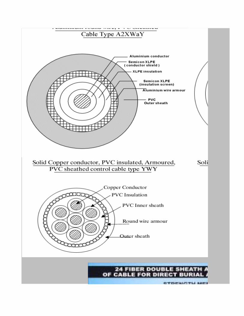
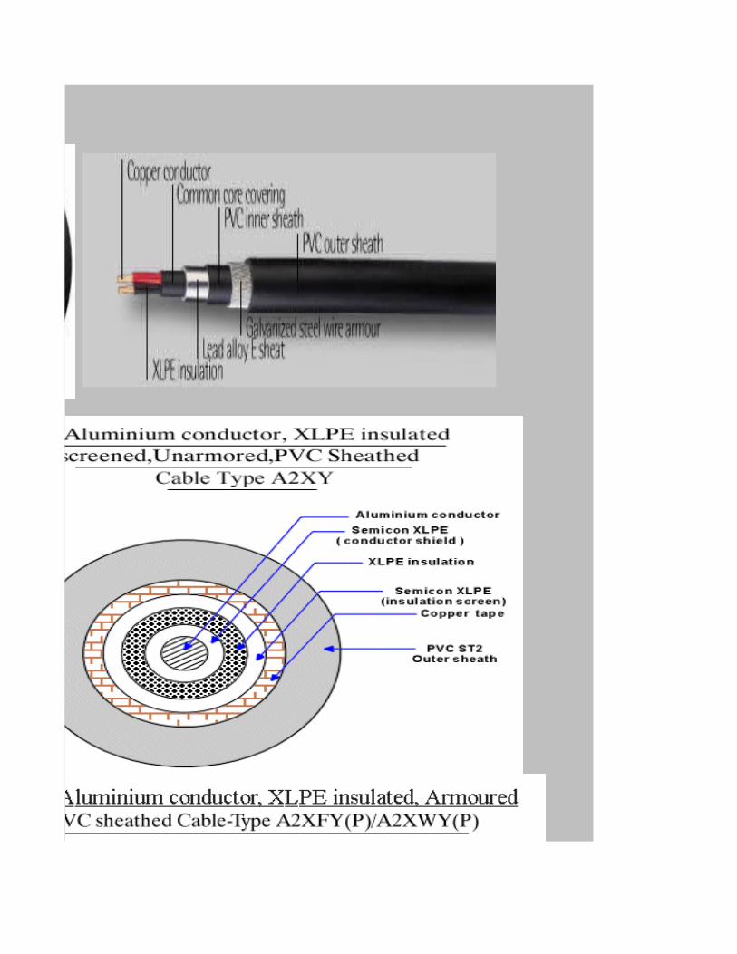
Diagram
Abbreviation
Designation
Armouring
Power and Control Cables
Instrumentation Cable
Telecommunication Cable
Fibre Optic Cable

HOME PAGE
NEXT PAGE

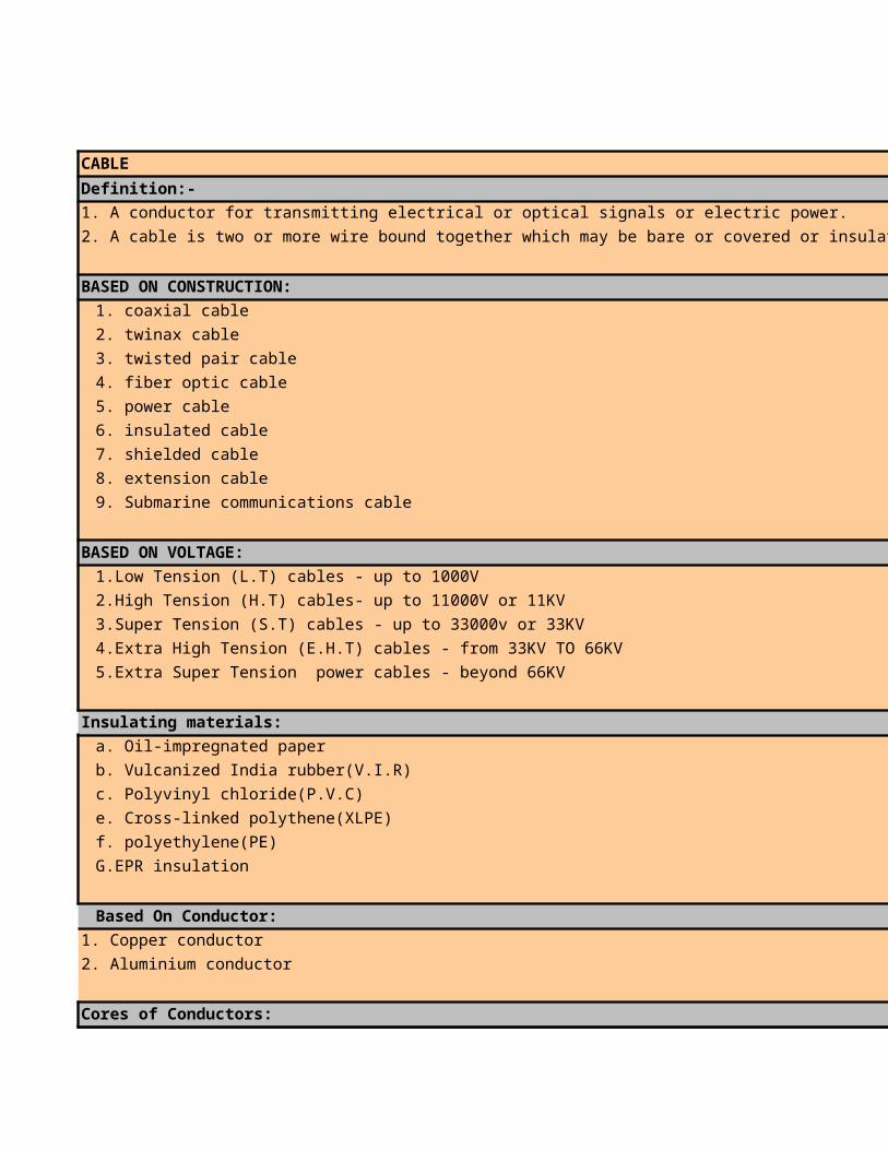
CABLE
Definition:-
1. A conductor for transmitting electrical or optical signals or electric power.
2. A cable is two or more wire bound together which may be bare or covered or insulated.
BASED ON CONSTRUCTION:
1. coaxial cable
2. twinax cable
3. twisted pair cable
4. fiber optic cable
5. power cable
6. insulated cable
7. shielded cable
8. extension cable
9. Submarine communications cable
BASED ON VOLTAGE:
1.Low Tension (L.T) cables - up to 1000V
2.High Tension (H.T) cables- up to 11000V or 11KV
3.Super Tension (S.T) cables - up to 33000v or 33KV
4.Extra High Tension (E.H.T) cables - from 33KV TO 66KV
5.Extra Super Tension power cables - beyond 66KV
Insulating materials:
a. Oil-impregnated paper
b. Vulcanized India rubber(V.I.R)
c. Polyvinyl chloride(P.V.C)
e. Cross-linked polythene(XLPE)
f. polyethylene(PE)
G.EPR insulation
Based On Conductor:
1. Copper conductor
2. Aluminium conductor
Cores of Conductors:
HOME PAGE
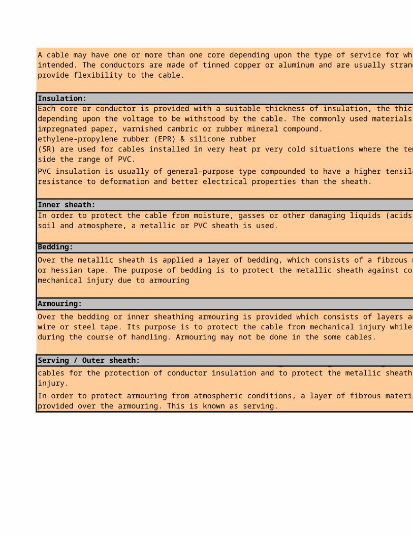
Insulation:
Inner sheath:
Bedding:
Armouring:
Serving / Outer sheath:
A cable may have one or more than one core depending upon the type of service for which it isintended. The conductors are made of tinned copper or aluminum and are usually stranded in order to provide flexibility to the cable.
Each core or conductor is provided with a suitable thickness of insulation, the thickness of layer depending upon the voltage to be withstood by the cable. The commonly used materials for insulation are impregnated paper, varnished cambric or rubber mineral compound.The insulation of wiring cables until recently was almost exclusively PVC. However significant quantities of low surface & fume (LSF) materials are now being employed. Other exceptions are that ethylene-propylene rubber (EPR) & silicone rubber(SR) are used for cables installed in very heat pr very cold situations where the temperature is out side the range of PVC.
PVC insulation is usually of general-purpose type compounded to have a higher tensile strength, better resistance to deformation and better electrical properties than the sheath.
In order to protect the cable from moisture, gasses or other damaging liquids (acids or alkalis) in the soil and atmosphere, a metallic or PVC sheath is used.
Over the metallic sheath is applied a layer of bedding, which consists of a fibrous material like just, or hessian tape. The purpose of bedding is to protect the metallic sheath against corrosion and from mechanical injury due to armouring
Over the bedding or inner sheathing armouring is provided which consists of layers and Galvanized steel wire or steel tape. Its purpose is to protect the cable from mechanical injury while laying it and during the course of handling. Armouring may not be done in the some cables.
It may not be out of place to mention here that bedding, armouring and serving is only applied to the cables for the protection of conductor insulation and to protect the metallic sheath from mechanical injury.
In order to protect armouring from atmospheric conditions, a layer of fibrous material or PVC type is provided over the armouring. This is known as serving.

STANDARD
BS
DIN
IEC
IEE
VDE
STANDARD NUMBER
BS 1231/63
BS 1441/69
BS 1442/69
BS 1557/54
BS 1843/52
BS 1862/59
BS 2004/61
BS 2008/53
BS 2791/66
BS 2899/P2/61
BS 3207/P1/60
BS 3249/60
BS 3346/61
BS 3360/61
BS 3361/61
BS 3454/62
BS 446/32
BS 480 PART1/54
BS 480 PART2/54
BS 480/P1/54
BS 480/P2/54
BS 6007/69
BS 608/56
BS 760/56
BS 883/49
BS 91/54
BS 937/58
BS 946/52
BS 977/41
HOME PAGE
NEXT PAGE
PREVIOUS PAGE

VDE 0278 PART 1/91
VDE 0278 PART 2/91
VDE 0278 PART 3/91
DIN 207 TEIL 23/86
DIN 207 TEIL 24/86
DIN 207 TEIL 3/85
DIN 207 TEIL 4/86
DIN 207 TEIL 5/86
DIN 207/86
DIN VDE 0245 PART101 --
DIN 250 TEIL 105/86
DIN 250 TEIL 209/85
DIN 250 TEIL 210/85
DIN 250 TEIL 211/86
DIN 250 TEIL 213/86
DIN 250 TEIL 501/85
DIN 250 TEIL 502/85
DIN 250 TEIL 602/85
DIN 250 TEIL 603/85
DIN 250 TEIL 802/85
DIN 250 TEIL 803/86
DIN 250 TEIL 806/85
DIN 250 TEIL 809/85
DIN 250 TEIL 811/85
DIN 250 TEIL 812/85
DIN 250 TEIL 813/85
DIN 250 TEIL 814/85
DIN 250 TEIL 815/85
DIN 250 TEIL 818/85
DIN VDE 0250 PART1 TO
DIN VDE 0253
DIN VDE 0262
DIN VDE 0265
DIN 266/85
DIN 271/86
DIN 281 TEIL 1/85
DIN 281 TEIL 101/85
DIN 281 TEIL 301/85
DIN 281 TEIL 302/85

DIN 281 TEIL 401/85
DIN 281 TEIL 402/85
DIN 281/85
DIN 282 TEIL 1/85
DIN 282 TEIL 601/85
DIN 282 TEIL 801/85
DIN 282 TEIL 804/85
DIN 282 TEIL 810/85
DIN 282 TEIL 817/85
DIN 284/85
DIN 295
DIN 472 TEIL 14/85
DIN 472 TEIL 211/85
DIN 472 TEIL 212/86
DIN 472 TEIL 212/86
DIN 472 TEIL 221/85
DIN 472 TEIL 222/86
DIN 472 TEIL 231/85
DIN 472 TEIL 232/85
DIN 472 TEIL 233/85
DIN 472 TEIL 251/85
DIN 472 TEIL 252/85
DIN 472 TEIL 253/85
DIN 472 TEIL 254/85
DIN 472 TEIL 503/85
DIN 472 TEIL 508/86
DIN 472 TEIL 509/86
DIN 472 TEIL 511/85
DIN 472 TEIL 512/85
DIN 472 TEIL 514/85
DIN 472 TEIL 515/85
DIN 472 TEIL 516/85
DIN 472 TEIL 517/85
DIN 472 TEIL 604/85
DIN 472 TEIL 605/85
DIN 472 TEIL 608/85
DIN 472 TEIL 609/85
DIN 472 TEIL 610/85
DIN 472 TEIL 611/85
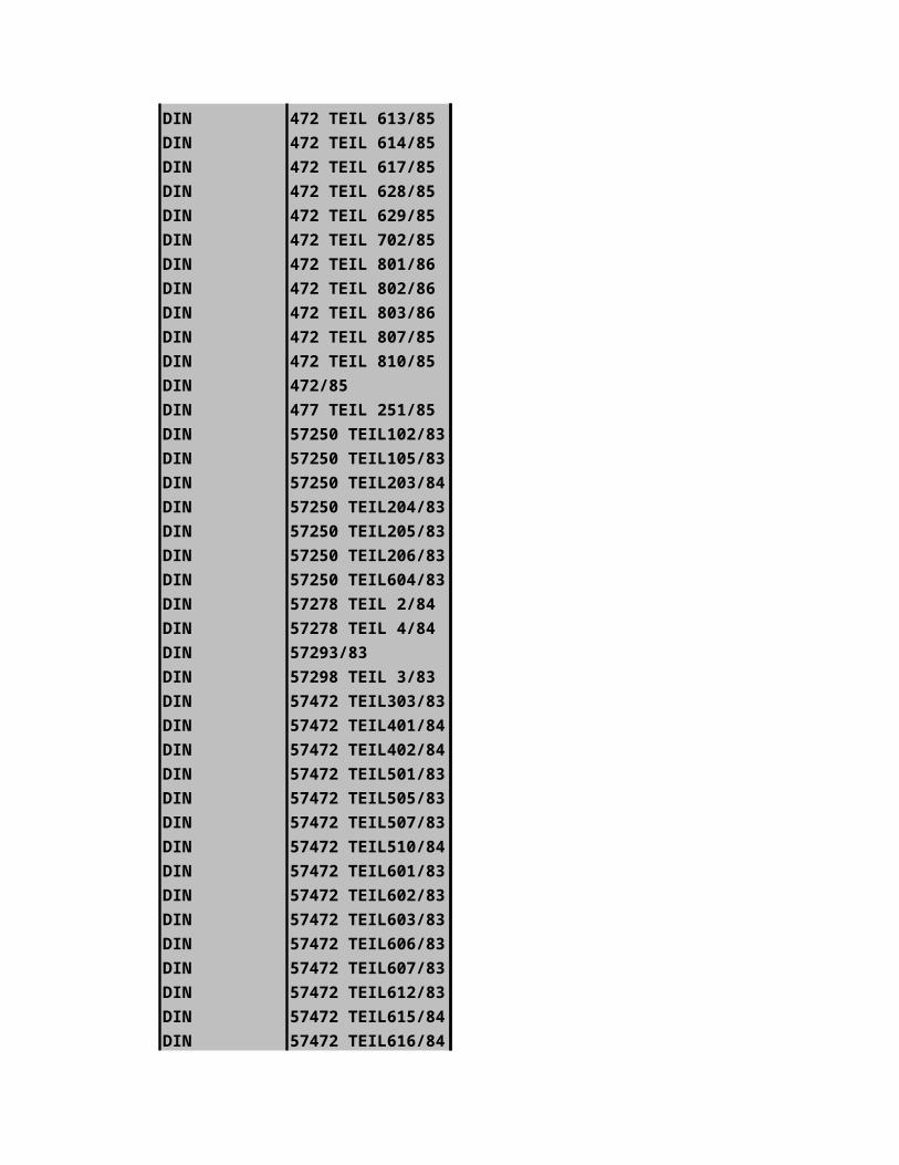
DIN 472 TEIL 613/85
DIN 472 TEIL 614/85
DIN 472 TEIL 617/85
DIN 472 TEIL 628/85
DIN 472 TEIL 629/85
DIN 472 TEIL 702/85
DIN 472 TEIL 801/86
DIN 472 TEIL 802/86
DIN 472 TEIL 803/86
DIN 472 TEIL 807/85
DIN 472 TEIL 810/85
DIN 472/85
DIN 477 TEIL 251/85
DIN 57250 TEIL102/8
DIN 57250 TEIL105/8
DIN 57250 TEIL203/8
DIN 57250 TEIL204/8
DIN 57250 TEIL205/8
DIN 57250 TEIL206/8
DIN 57250 TEIL604/8
DIN 57278 TEIL 2/84
DIN 57278 TEIL 4/84
DIN 57293/83
DIN 57298 TEIL 3/83
DIN 57472 TEIL303/8
DIN 57472 TEIL401/8
DIN 57472 TEIL402/8
DIN 57472 TEIL501/8
DIN 57472 TEIL505/8
DIN 57472 TEIL507/8
DIN 57472 TEIL510/8
DIN 57472 TEIL601/8
DIN 57472 TEIL602/8
DIN 57472 TEIL603/8
DIN 57472 TEIL606/8
DIN 57472 TEIL607/8
DIN 57472 TEIL612/8
DIN 57472 TEIL615/8
DIN 57472 TEIL616/8

DIN 57472 TEIL704/8
DIN 57472 TEIL804/8
DIN 57472 TEIL808/8
DIN 57472 TEIL809/8
DIN 57472 TEIL812/8
DIN 57472 TEIL813/8
DIN 57472 TEIL814/8
DIN 57887 TEIL3/84
DIN 815/85
DIN 887 TEIL 2/86
DIN 891 TEIL 5/85
DIN 89158/75
IEC 141-2/63
IEC 141-3/63
IEC 173/64
IEC 183/84
IEC 189-2/81
IEC 189-3/88
IEC 189-5/80
IEC 189-6/82
IEC 227/67
IEC 227-1/79
IEC 227-2/79
IEC 227-3/79
IEC 227-4/77
IEC 227-5 AM1/87
IEC 227-5/79
IEC 227-6
IEC 228/78
IEC 228A/82
IEC 230/66
IEC 245/67
IEC 245-4 AM1/85
IEC 245-4/80
IEC 245-5 AM1/85
IEC 245-5/80
IEC 245-6 AM1/85
IEC 245-6/80
IEC 287/82

IEC 304/82
IEC 313/83
IEC 331/70
IEC 332-1/79
IEC 332-3 AM2/87
IEC 332-3/82
IEC 465/88
IEC 488/74
IEC 502
IEC 502 AM2/87
IEC 502/83
IEC 50-461/84
IEC 538/76
IEC 538A/80
IEC 540 AM1/84
IEC 540/82
IEC 55-1/78
IEC 55-2/81
IEC 60502-2/97-04
IEC 702/81
IEC 702-1/88
IEC 702-2/86
IEC 708-1 AM1/83
IEC 708-1 AM2/85
IEC 708-1 AM3/81
IEC 708-1/81
IEC 708-2 AM1/83
IEC 708-2/81
IEC 728-1/86
IEC 754-1/82
IEC 885-1/87
IEC 92-3 AM1/69
IEC 92-3 AM2/71
IEC 92-3 AM3/73
IEC 92-3 AM4/74
IEC 92-3 AM4/74
IEC 92-3 AM5/79
IEC 96-3/82

ABBREVIATIONS
BRITISH STANDARD (GREAT BRITAIN)
DEUTSCHES INSTITUTE FOR NORMUNG (GERMANY)
INTERNATIONAL ELECTRO TECHNICAL COMMISSION (INTERNATIONAL)
INSTITUTION OF ELECTRICAL ENGINEERS (GREAT BRITAIN)
VEREIN DEUTSCHER ELEKTROINGENIEURE (GERMANY)
DESCRIPTION
PVC-INSULATED CABLES FOR POWER SWITCHGEAR WIRING
GALVANIZED STEEL WIRE FOR ARMOURING SUBMARINE CABLES
GALVANIZED MILD STEEL WIRE FOR ARMOURING CABLES
POLYTHNE-INSULATED CABLES SHEATHED WITH PVC FOR ELECTRICAL
COLOUR CODE FOR TWIN COMPENSATING CABLES FOR THERMOCOUPLES
CABLES FOR VEHICLES
PVC-INSULATED CABLES AND FLEXIBLE CORDS FOR ELECTRIC POWER
WIRE ARMOURED CABLES FOR COLLIERIES
ALUMINIUM CONDUCTORS IN INSULATED CABLES
RUBBER INSULATION AND SHEATH OF ELECTRIC CABLE/SILICONE RUBBER
MINERAL-INSULATED CABLES/COPPER SHEATHED CABLES WITH COPPER
CABLES AND FLEXIBLE CORDS INSULATED WITH VARNISHED CAMBRIC
ARMOURED PVC-INSULATED CABLES
COPPER CONDUCTORS IN INSULATED CABLES AND CORDS
COPPER CONDUCTORS IN INSULATED CABLES AND CORDS
3.3 KV 300A INTERCHANGEABLE BOLTED FLAMEPROOF CABLE
BRAINED CABLES WITH COPPER CONDUCTORS FOR OVERHEAD TRANSMISSION
LEAD OR LEAD SHEATHED CABLES
ALLUMINIUM SHEATHED CABLES
LEAD OR LEAD ALLOY SHEATHED CABLES
ALUMINIUM SHEATHED CABLES
ELASTOMER-INSULATED CABLES FOR ELECTRIC POWER AND LIGHTING
VARNISHED CAMBRIC INSULATED CABLES FOR ELECTRICITY SUPPLY
WIRE-ARMOURED PAPER-INSULATED CABLES FOR USE IN MINES
CABLE AND FLEXIBLE CORDS FOR ELECTRICAL EQUIPMENT OF SHIPS
ELECTRICAL CABLE SOLDERING SOCKETS
FLEXIBLE CABLE FOR MINERS CAP LAMPS
DESIGNATION OF THE STRUCTURE OF SINGLE PLIED AND CABLED
FLEXIBLE CABLES FOR ELECTRICAL LIFTS
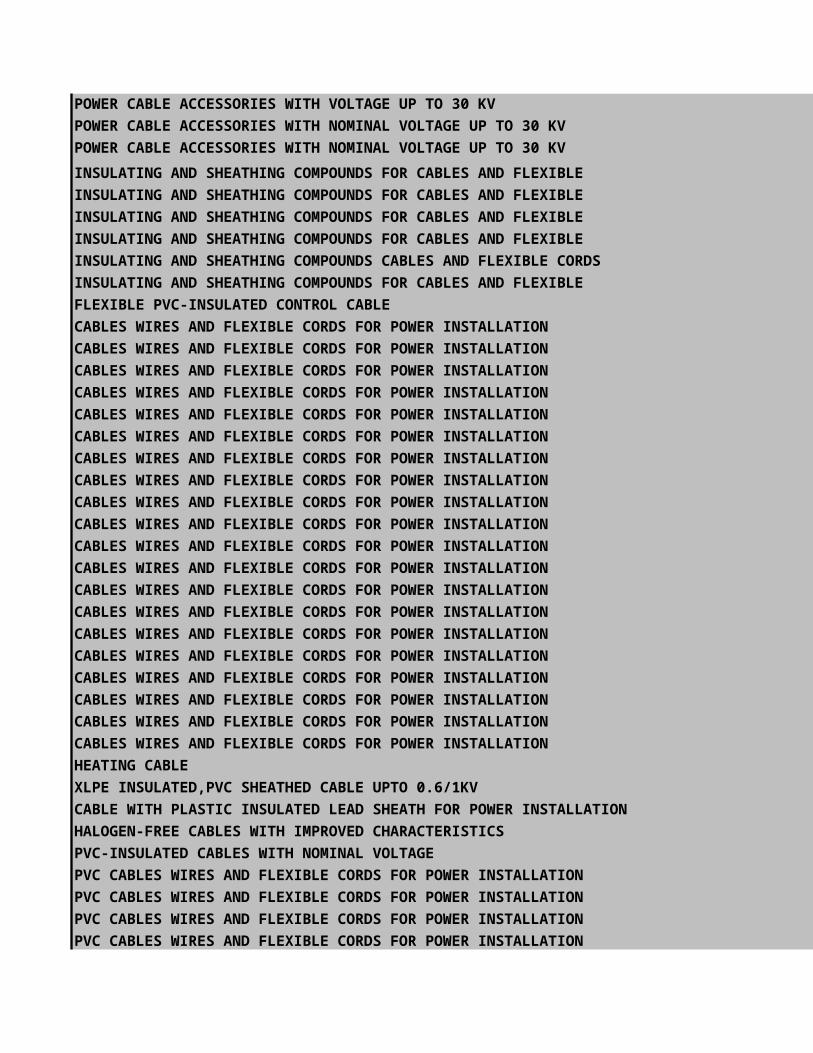
POWER CABLE ACCESSORIES WITH VOLTAGE UP TO 30 KV
POWER CABLE ACCESSORIES WITH NOMINAL VOLTAGE UP TO 30 KV
POWER CABLE ACCESSORIES WITH NOMINAL VOLTAGE UP TO 30 KV
INSULATING AND SHEATHING COMPOUNDS FOR CABLES AND FLEXIBLE
INSULATING AND SHEATHING COMPOUNDS FOR CABLES AND FLEXIBLE
INSULATING AND SHEATHING COMPOUNDS FOR CABLES AND FLEXIBLE
INSULATING AND SHEATHING COMPOUNDS FOR CABLES AND FLEXIBLE
INSULATING AND SHEATHING COMPOUNDS CABLES AND FLEXIBLE CORDS
INSULATING AND SHEATHING COMPOUNDS FOR CABLES AND FLEXIBLE
FLEXIBLE PVC-INSULATED CONTROL CABLE
CABLES WIRES AND FLEXIBLE CORDS FOR POWER INSTALLATION
CABLES WIRES AND FLEXIBLE CORDS FOR POWER INSTALLATION
CABLES WIRES AND FLEXIBLE CORDS FOR POWER INSTALLATION
CABLES WIRES AND FLEXIBLE CORDS FOR POWER INSTALLATION
CABLES WIRES AND FLEXIBLE CORDS FOR POWER INSTALLATION
CABLES WIRES AND FLEXIBLE CORDS FOR POWER INSTALLATION
CABLES WIRES AND FLEXIBLE CORDS FOR POWER INSTALLATION
CABLES WIRES AND FLEXIBLE CORDS FOR POWER INSTALLATION
CABLES WIRES AND FLEXIBLE CORDS FOR POWER INSTALLATION
CABLES WIRES AND FLEXIBLE CORDS FOR POWER INSTALLATION
CABLES WIRES AND FLEXIBLE CORDS FOR POWER INSTALLATION
CABLES WIRES AND FLEXIBLE CORDS FOR POWER INSTALLATION
CABLES WIRES AND FLEXIBLE CORDS FOR POWER INSTALLATION
CABLES WIRES AND FLEXIBLE CORDS FOR POWER INSTALLATION
CABLES WIRES AND FLEXIBLE CORDS FOR POWER INSTALLATION
CABLES WIRES AND FLEXIBLE CORDS FOR POWER INSTALLATION
CABLES WIRES AND FLEXIBLE CORDS FOR POWER INSTALLATION
CABLES WIRES AND FLEXIBLE CORDS FOR POWER INSTALLATION
CABLES WIRES AND FLEXIBLE CORDS FOR POWER INSTALLATION
CABLES WIRES AND FLEXIBLE CORDS FOR POWER INSTALLATION
HEATING CABLE
XLPE INSULATED,PVC SHEATHED CABLE UPTO 0.6/1KV
CABLE WITH PLASTIC INSULATED LEAD SHEATH FOR POWER INSTALLATION
HALOGEN-FREE CABLES WITH IMPROVED CHARACTERISTICS
PVC-INSULATED CABLES WITH NOMINAL VOLTAGE
PVC CABLES WIRES AND FLEXIBLE CORDS FOR POWER INSTALLATION
PVC CABLES WIRES AND FLEXIBLE CORDS FOR POWER INSTALLATION
PVC CABLES WIRES AND FLEXIBLE CORDS FOR POWER INSTALLATION
PVC CABLES WIRES AND FLEXIBLE CORDS FOR POWER INSTALLATION

PVC CABLES WIRES AND FLEXIBLE CORDS FOR POWER INSTALLATION
PVC CABLES WIRES AND FLEXIBLE CORDS FOR POWER INSTALLATION
PVC CABLES WIRES AND FLEXIBLE CORDS FOR POWER INSTALLATION
RUBBER CABLES WIRES AND FLEXIBLE CORDS FOR POWER
RUBBER CABLES WIRES AND FLEXIBLE CORDS FOR POWER
RUBBER CABLES WIRES AND FLEXIBLE CORDS FOR POWER
RUBBER CABLES WIRES FOR FLEXIBLE CORDS FOR POWER
RUBBER CABLES WIRES AND FLEXIBLE CORDS FOR POWER
RUBBER CABLES WIRES AND FLEXIBLE CORDS FOR POWER
MINERAL INSULATED CABLES WITH NOMINAL VOLTAGE UP TO 750V
CONDUCTORS OF CABLES WIRES AND FLEXIBLE CORDS FOR POWER
TESTING OF CABLES WIRES AND FLEXIBLE CORDS FAILURE ON
TESTING OF CABLES WIRES AND FLEXIBLE CORDS TOLERANCE FIELDS
TESTING OF CABLES WIRES AND FLEXIBLE CORDS CORE AND CLADDING
TESTING OF CABLES WIRES AND FLEXIBLE CORDS CORE AND CLADDING
TESTING OF CABLES WIRES AND FLEXIBLE CORDS TENSIBLE
TESTING OF CABLES WIRES AND FLEXIBLE CORDS TENSIBLE TEST ON
TESTING OF CABLES WIRES AND FLEXIBLE CORDS CHANGING
TESTING OF CABLES WIRES AND FLEXIBLE CORDS CHANGING
TESTING OF CABLES WIRES AND FLEXIBLE CORDS CHANGING
TESTING OF CABLES WIRES AND FLEXIBLE CORDS BACKSCATTERING
TESTING OF CABLES WIRES AND FLEXIBLE CORDS ATTENUATION
TESTING OF CABLES WIRES AND FLEXIBLE CORDS BANDWIDTH
TESTING OF CABLES WIRES AND FLEXIBLE CORDS NUMERICAL
TESTING OF CABLES WIRES AND FLEXIBLE CORDS SURFACE
TESTING OF CABLES WIRES AND FLEXIBLE CORDS DIELECTRIC
TESTING OF CABLES WIRES AND FLEXIBLE CORDS DIELECTRIC
TESTING OF CABLES WIRES AND FLEXIBLE CORDS IMPULSE TEST
TESTING OF CABLES WIRES AND FLEXIBLE CORDS RESISTANCE
TESTING OF CABLES WIRES AND FLEXIBLE CORDS FAILURE ON
TESTING OF CABLES WIRES AND FLEXIBLE CORDS ATTENUATION
TESTING OF CABLES WIRES AND FLEXIBLE CORDS CHARACTERISTICS
TESTING OF CABLES WIRES AND FLEXIBLE CORDS CROSSTALK
TESTING OF CABLES WIRES AND FLEXIBLE CORDS TIGHTNESS
TESTING OF CABLES INSULATED WIRES AND FLEXIBLE CORDS
TESTING OF CABLES WIRES AND FLEXIBLE CORDS HEAT-SHOCK-
TESTING OF CABLES WIRES AND FLEXIBLE CORDS PRESSURE TEST
TESTING OF CABLES WIRES AND FLEXIBLE CORDS BENDING TEST
TESTING OF INSULATED CABLES AND FLEXIBLE CORDS COLD IMPACT
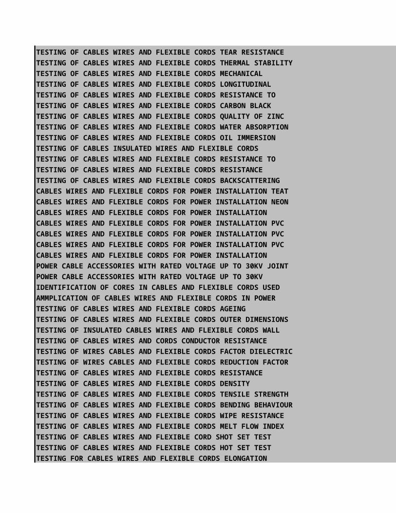
TESTING OF CABLES WIRES AND FLEXIBLE CORDS TEAR RESISTANCE
TESTING OF CABLES WIRES AND FLEXIBLE CORDS THERMAL STABILITY
TESTING OF CABLES WIRES AND FLEXIBLE CORDS MECHANICAL
TESTING OF CABLES WIRES AND FLEXIBLE CORDS LONGITUDINAL
TESTING OF CABLES WIRES AND FLEXIBLE CORDS RESISTANCE TO
TESTING OF CABLES WIRES AND FLEXIBLE CORDS CARBON BLACK
TESTING OF CABLES WIRES AND FLEXIBLE CORDS QUALITY OF ZINC
TESTING OF CABLES WIRES AND FLEXIBLE CORDS WATER ABSORPTION
TESTING OF CABLES WIRES AND FLEXIBLE CORDS OIL IMMERSION
TESTING OF CABLES INSULATED WIRES AND FLEXIBLE CORDS
TESTING OF CABLES WIRES AND FLEXIBLE CORDS RESISTANCE TO
TESTING OF CABLES WIRES AND FLEXIBLE CORDS RESISTANCE
TESTING OF CABLES WIRES AND FLEXIBLE CORDS BACKSCATTERING
CABLES WIRES AND FLEXIBLE CORDS FOR POWER INSTALLATION TEAT
CABLES WIRES AND FLEXIBLE CORDS FOR POWER INSTALLATION NEON
CABLES WIRES AND FLEXIBLE CORDS FOR POWER INSTALLATION
CABLES WIRES AND FLEXIBLE CORDS FOR POWER INSTALLATION PVC
CABLES WIRES AND FLEXIBLE CORDS FOR POWER INSTALLATION PVC
CABLES WIRES AND FLEXIBLE CORDS FOR POWER INSTALLATION PVC
CABLES WIRES AND FLEXIBLE CORDS FOR POWER INSTALLATION
POWER CABLE ACCESSORIES WITH RATED VOLTAGE UP TO 30KV JOINT
POWER CABLE ACCESSORIES WITH RATED VOLTAGE UP TO 30KV
IDENTIFICATION OF CORES IN CABLES AND FLEXIBLE CORDS USED
AMMPLICATION OF CABLES WIRES AND FLEXIBLE CORDS IN POWER
TESTING OF CABLES WIRES AND FLEXIBLE CORDS AGEING
TESTING OF CABLES WIRES AND FLEXIBLE CORDS OUTER DIMENSIONS
TESTING OF INSULATED CABLES WIRES AND FLEXIBLE CORDS WALL
TESTING OF CABLES WIRES AND CORDS CONDUCTOR RESISTANCE
TESTING OF WIRES CABLES AND FLEXIBLE CORDS FACTOR DIELECTRIC
TESTING OF WIRES CABLES AND FLEXIBLE CORDS REDUCTION FACTOR
TESTING OF CABLES WIRES AND FLEXIBLE CORDS RESISTANCE
TESTING OF CABLES WIRES AND FLEXIBLE CORDS DENSITY
TESTING OF CABLES WIRES AND FLEXIBLE CORDS TENSILE STRENGTH
TESTING OF CABLES WIRES AND FLEXIBLE CORDS BENDING BEHAVIOUR
TESTING OF CABLES WIRES AND FLEXIBLE CORDS WIPE RESISTANCE
TESTING OF CABLES WIRES AND FLEXIBLE CORDS MELT FLOW INDEX
TESTING OF CABLES WIRES AND FLEXIBLE CORD SHOT SET TEST
TESTING OF CABLES WIRES AND FLEXIBLE CORDS HOT SET TEST
TESTING FOR CABLES WIRES AND FLEXIBLE CORDS ELONGATION
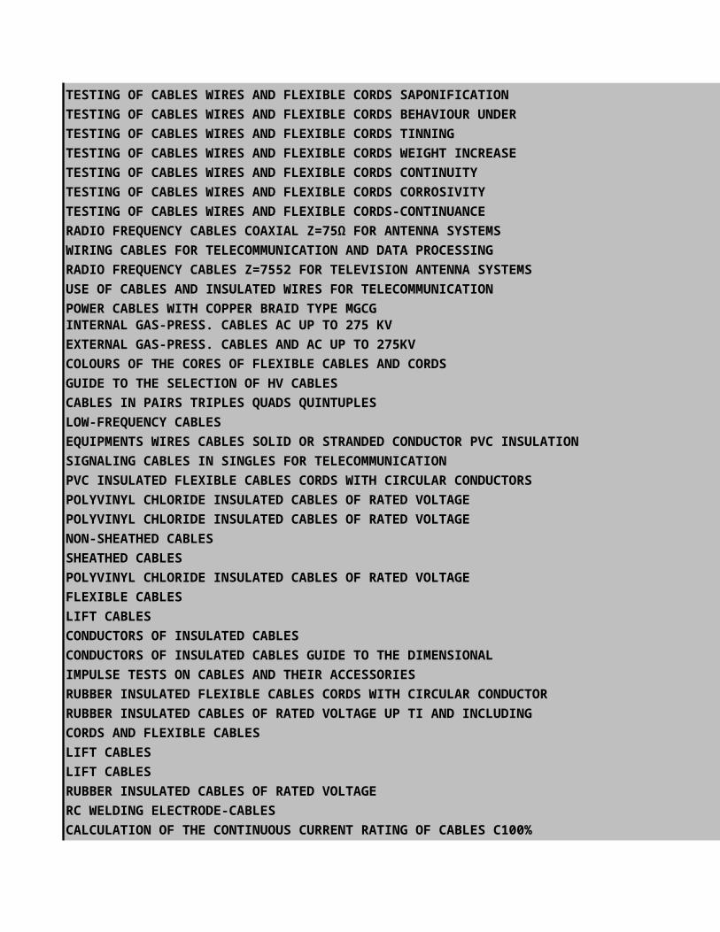
TESTING OF CABLES WIRES AND FLEXIBLE CORDS SAPONIFICATION
TESTING OF CABLES WIRES AND FLEXIBLE CORDS BEHAVIOUR UNDER
TESTING OF CABLES WIRES AND FLEXIBLE CORDS TINNING
TESTING OF CABLES WIRES AND FLEXIBLE CORDS WEIGHT INCREASE
TESTING OF CABLES WIRES AND FLEXIBLE CORDS CONTINUITY
TESTING OF CABLES WIRES AND FLEXIBLE CORDS CORROSIVITY
TESTING OF CABLES WIRES AND FLEXIBLE CORDS-CONTINUANCE
RADIO FREQUENCY CABLES COAXIAL Z=75Ω FOR ANTENNA SYSTEMS
WIRING CABLES FOR TELECOMMUNICATION AND DATA PROCESSING
RADIO FREQUENCY CABLES Z=7552 FOR TELEVISION ANTENNA SYSTEMS
USE OF CABLES AND INSULATED WIRES FOR TELECOMMUNICATION
POWER CABLES WITH COPPER BRAID TYPE MGCG
INTERNAL GAS-PRESS. CABLES AC UP TO 275 KV
EXTERNAL GAS-PRESS. CABLES AND AC UP TO 275KV
COLOURS OF THE CORES OF FLEXIBLE CABLES AND CORDS
GUIDE TO THE SELECTION OF HV CABLES
CABLES IN PAIRS TRIPLES QUADS QUINTUPLES
LOW-FREQUENCY CABLES
EQUIPMENTS WIRES CABLES SOLID OR STRANDED CONDUCTOR PVC INSULATION
SIGNALING CABLES IN SINGLES FOR TELECOMMUNICATION
PVC INSULATED FLEXIBLE CABLES CORDS WITH CIRCULAR CONDUCTORS
POLYVINYL CHLORIDE INSULATED CABLES OF RATED VOLTAGE
POLYVINYL CHLORIDE INSULATED CABLES OF RATED VOLTAGE
NON-SHEATHED CABLES
SHEATHED CABLES
POLYVINYL CHLORIDE INSULATED CABLES OF RATED VOLTAGE
FLEXIBLE CABLES
LIFT CABLES
CONDUCTORS OF INSULATED CABLES
CONDUCTORS OF INSULATED CABLES GUIDE TO THE DIMENSIONAL
IMPULSE TESTS ON CABLES AND THEIR ACCESSORIES
RUBBER INSULATED FLEXIBLE CABLES CORDS WITH CIRCULAR CONDUCTOR
RUBBER INSULATED CABLES OF RATED VOLTAGE UP TI AND INCLUDING
CORDS AND FLEXIBLE CABLES
LIFT CABLES
LIFT CABLES
RUBBER INSULATED CABLES OF RATED VOLTAGE
RC WELDING ELECTRODE-CABLES
CALCULATION OF THE CONTINUOUS CURRENT RATING OF CABLES C100%
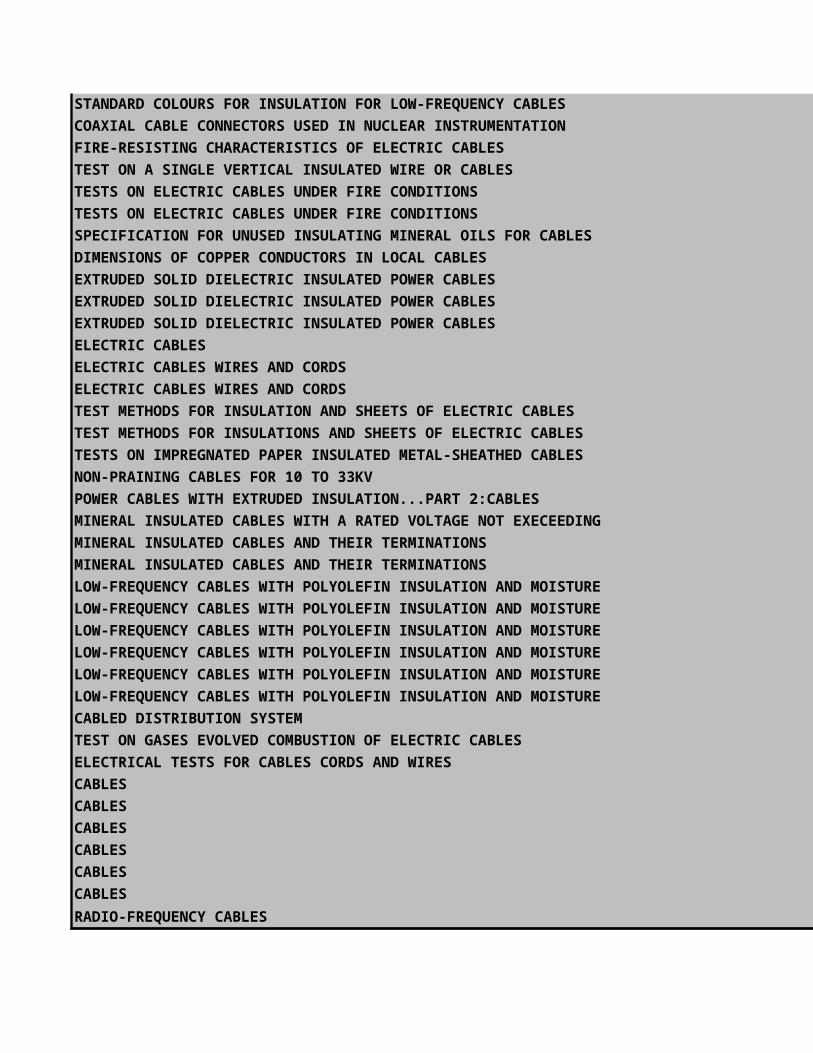
STANDARD COLOURS FOR INSULATION FOR LOW-FREQUENCY CABLES
COAXIAL CABLE CONNECTORS USED IN NUCLEAR INSTRUMENTATION
FIRE-RESISTING CHARACTERISTICS OF ELECTRIC CABLES
TEST ON A SINGLE VERTICAL INSULATED WIRE OR CABLES
TESTS ON ELECTRIC CABLES UNDER FIRE CONDITIONS
TESTS ON ELECTRIC CABLES UNDER FIRE CONDITIONS
SPECIFICATION FOR UNUSED INSULATING MINERAL OILS FOR CABLES
DIMENSIONS OF COPPER CONDUCTORS IN LOCAL CABLES
EXTRUDED SOLID DIELECTRIC INSULATED POWER CABLES
EXTRUDED SOLID DIELECTRIC INSULATED POWER CABLES
EXTRUDED SOLID DIELECTRIC INSULATED POWER CABLES
ELECTRIC CABLES
ELECTRIC CABLES WIRES AND CORDS
ELECTRIC CABLES WIRES AND CORDS
TEST METHODS FOR INSULATION AND SHEETS OF ELECTRIC CABLES
TEST METHODS FOR INSULATIONS AND SHEETS OF ELECTRIC CABLES
TESTS ON IMPREGNATED PAPER INSULATED METAL-SHEATHED CABLES
NON-PRAINING CABLES FOR 10 TO 33KV
POWER CABLES WITH EXTRUDED INSULATION...PART 2:CABLES
MINERAL INSULATED CABLES WITH A RATED VOLTAGE NOT EXECEEDING
MINERAL INSULATED CABLES AND THEIR TERMINATIONS
MINERAL INSULATED CABLES AND THEIR TERMINATIONS
LOW-FREQUENCY CABLES WITH POLYOLEFIN INSULATION AND MOISTURE
LOW-FREQUENCY CABLES WITH POLYOLEFIN INSULATION AND MOISTURE
LOW-FREQUENCY CABLES WITH POLYOLEFIN INSULATION AND MOISTURE
LOW-FREQUENCY CABLES WITH POLYOLEFIN INSULATION AND MOISTURE
LOW-FREQUENCY CABLES WITH POLYOLEFIN INSULATION AND MOISTURE
LOW-FREQUENCY CABLES WITH POLYOLEFIN INSULATION AND MOISTURE
CABLED DISTRIBUTION SYSTEM
TEST ON GASES EVOLVED COMBUSTION OF ELECTRIC CABLES
ELECTRICAL TESTS FOR CABLES CORDS AND WIRES
CABLES
CABLES
CABLES
CABLES
CABLES
CABLES
RADIO-FREQUENCY CABLES

ARMOUR CABLE
HOME PAGENEXT PAGE
PREVIOUS PAGE


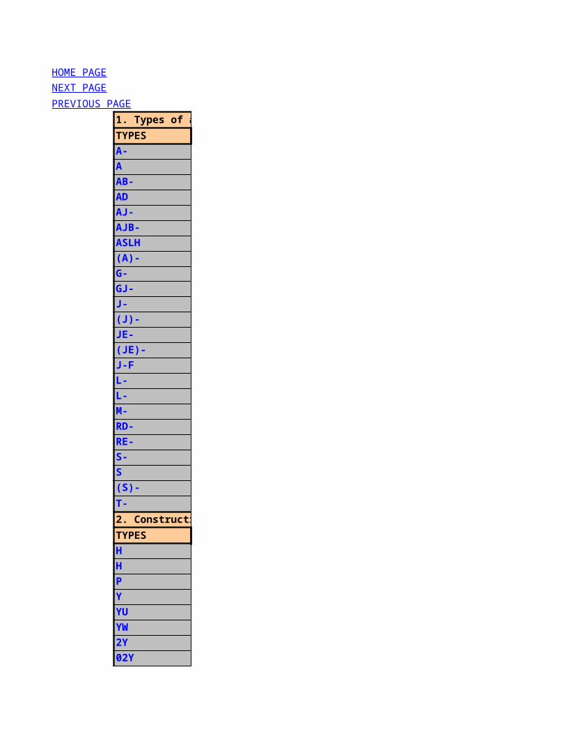
1. Types of applications
TYPES
A-
A
AB-
AD
AJ-
AJB-
ASLH
(A)-
G-
GJ-
J-
(J)-
JE-
(JE)-
J-F
L-
L-
M-
RD-
RE-
S-
S
(S)-
T-
2. Construction characteristics under the sheath:
TYPES
H
H
P
Y
YU
YW
2Y
02Y
02YS
3Y
6Y
HOME PAGE
NEXT PAGE
PREVIOUS PAGE

9Y
09Y
09YS
3. Construction characteristics under the sheath:
TYPES
A
C
D
F
0F
(K)
(St)
Y
2Y
(Z)
4. Cable sheath:
TYPES
E
H
L
(L)2Y
LD
M
Mz
T2Y
W
Y
Ymb
YU
YW
Yv
2Y
2Yv
4Y
6Y(Zg)2Y5. Construction characteristics over the sheath:
TYPES
A
B
(1B...)
(2B...)

C
D
ib
Q
Y
Y
Yv
2Y
2Y
2Yv
6. Stranding elements/kinds of stranding:
TYPES
BD
BDIMF
(C)
DM
DIMF
e
F
Kx
LG
Li
PCM
Pr
ST
ST O
ST I
ST II
ST III
ST IV
ST V
ST VI
TF
VIMF
Y
YV
7. Others:
TYPES
EIB
E30
E90
FE180
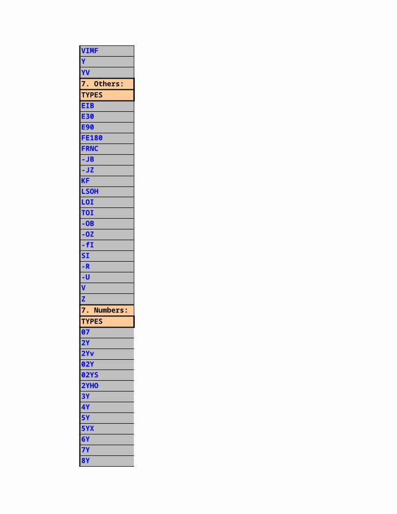
FRNC
-JB
-JZ
KF
LSOH
LOI
TOI
-OB
-OZ
-fI
SI
-R
-U
V
Z
7. Numbers:
TYPES
07
2Y
2Yv
02Y
02YS
2YHO
3Y
4Y
5Y
5YX
6Y
7Y
8Y
9Y
10Y
11Y
12Y
13Y
31Y
41Y
51Y
71Y
91Y
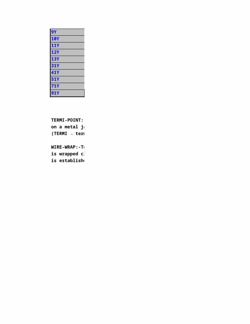
TERMI-POINT:-Technique unsoldered connection technique by means of a special tool where the insulation is stripped o
on a metal jamb and is put on electrically conductive with a clip (clamp connection)
(TERMI → termination) (Mini-, Standard-, Maxi-Termi-Point)
WIRE-WRAP:-Technique unsoldered connection technique by means of a special tool where the stripped-off conductor
is wrapped closely around a metal bolt. By this procedure an electrically conductive connection
is established.
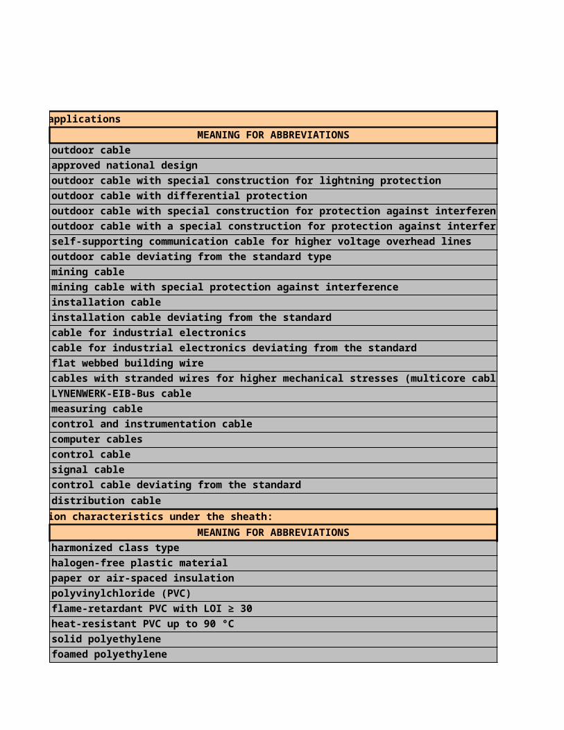
1. Types of applications
MEANING FOR ABBREVIATIONS
outdoor cable
approved national design
outdoor cable with special construction for lightning protection
outdoor cable with differential protection
outdoor cable with special construction for protection against interfere
outdoor cable with a special construction for protection against interfe
self-supporting communication cable for higher voltage overhead lines
outdoor cable deviating from the standard type
mining cable
mining cable with special protection against interference
installation cable
installation cable deviating from the standard
cable for industrial electronics
cable for industrial electronics deviating from the standard
flat webbed building wire
cables with stranded wires for higher mechanical stresses (multicore ca
LYNENWERK-EIB-Bus cable
measuring cable
control and instrumentation cable
computer cables
control cable
signal cable
control cable deviating from the standard
distribution cable
2. Construction characteristics under the sheath:
MEANING FOR ABBREVIATIONS
harmonized class type
halogen-free plastic material
paper or air-spaced insulation
polyvinylchloride (PVC)
flame-retardant PVC with LOI ≥ 30
heat-resistant PVC up to 90 °C
solid polyethylene
foamed polyethylene
foamed polyethylene with a solid PE sheath (foam-skin)
polystyrol (styroflex)
teflon (FEP)

polypropylene (PP)
foam polypropylene
foamed polypropylene with a sheath of unfoamed polyolefin
3. Construction characteristics under the sheath:
MEANING FOR ABBREVIATIONS
covering made of Al-wires
screen made of tinned copper wire braid
covering made of copper wires
filling with petrol jelly
filling with so-called ”FÜLLNIDZ” (filling material with low dielectric
screen made of copper tape; 0,12 mm thick (previous type)
static screen made of unilateral coated Al-foil with tinned copper drain
PVC inner sheath
PE inner sheath
strain-resistant braid of galvanized flat steel wires with a defined break
4. Cable sheath:
MEANING FOR ABBREVIATIONS
corrosion protection sheath (sheath with embedded plastic tape)
halogen-free plastic sheath
aluminium sheath
laminated sheath of an aluminium tape coated with plastic foil on one o
corrugated aluminium sheath
lead sheath
lead sheath with a hardening addition
supporting strand made of steel with PE sheath
corrugated steel sheath
polyvinylchloride sheath (PVC)
flame-retardant PVC sheath with LOI ≥ 30
flame-retardant PVC sheath with LOI ≥ 30
heat-resistant PVC sheath up to 90 °C
reinforced PVC sheath
polyethylene sheath (PE)
reinforced PE sheath
polyamide sheath (PA)
Teflon sheath (FEP)stress relieving elements made of glass yarn embedded in the PE outer
5. Construction characteristics over the sheath:
MEANING FOR ABBREVIATIONS
covering made of aluminium wires
armouring made of one or several steel tapes, galvanized or covered with
one layer of steel tape... thickness of the steel tape in mm
two layers of steel tape... thickness of the steel tape in mm

protection sheath made of jute or viscous mass
covering made of copper wires
induction protective armouring (previous type)
strain-resistant armouring in the form of a braid of flat, galvanized stee
PVC protective sheath (inner sheath)
PVC protective sheath (outer sheath)
reinforced outer sheath of PVC
PE inner sheath
PE outer sheath
PE reinforced outer sheath
6. Stranding elements/kinds of stranding:
MEANING FOR ABBREVIATIONS
stranding in bundles
bundles in metal foil
screen made of a copper wire braid over a pair
multiple-twin quad (2 pairs stranded with each other)
triples in metal foil
tinned copper drain wire
star quad with use of phantom circuits (German Railways)
coaxial pair
stranding in layers
strand
stranding elements for PCM use (pulse-code-modulation)
perforated pilot wire
star quad with use of phantom circuits (in general)
star quad (800 Hz) with from group I up to IV deviating requirements
star quad (800 Hz) without use of phantom circuits for longer distance
star quad (800 Hz) with increased requirements compared to group II
star quad with requirements at 800 Hz
star quad with requirements up to 120 kHz
star quad with requirements up to 550 kHz
star quad with requirements up to 17 MHz
stranding elements for carrier frequency use
quads in metal foil
jumper wire of a bare copper conductor with PVC insulation
jumper wire of a tinned conductor with PVC insulation
MEANING FOR ABBREVIATIONS
European Installation Bus
flame-retardant, halogen-free cables with a function integrity up to 30 m
as for E30, but up to 90 minutes
flame-retardant, halogen-free cables with insulation integrity up to 18
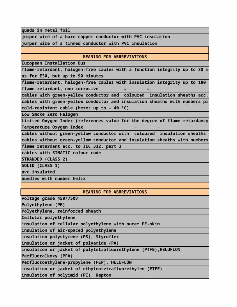
flame retardant, non corrosive
cables with green-yellow conductor and ”coloured” insulation sheaths ac
cables with green-yellow conductor and insulation sheaths with number
cold-resistant cable (here: up to – 40 °C)
Low Smoke Zero Halogen
Limited Oxygen Index (references value for the degree of flame-retardancy)
Temperature Oxygen Index
cables without green-yellow conductor with ”coloured” insulation sheath
cables without green-yellow conductor and insulation sheaths with num
flame retardant acc. to IEC 332, part 3
cables with SIMATIC-colour code
STRANDED (CLASS 2)
SOLID (CLASS 1)
pvc insulated
bundles with number helix
7. Numbers:
MEANING FOR ABBREVIATIONS
voltage grade 450/750v
Polyethylene (PE)
Polyethylene, reinforced sheath
Cellular polyethylene
insulation of cellular polyethylene with outer PE-skin
insulation of air-spaced polyethylene
insulation polystyrene (PS), Styroflex
insulation or jacket of polyamide (PA)
insulation or jacket of polytetrafluorethylene (PTFE),HELUFLON
Perfluoralkoxy (PFA)
Perfluoroethylene-propylene (FEP), HELUFLON
insulation or jacket of ethylentetrafluorethylen (ETFE)
insulation of polyimid (PI), Kapton
polypropylene (PP)
PVDF, Polyvinylidene fluoride
polyurethane (PUR)
TPE-E, TPE
TPE-EE, TPE on base of Polyester-Ester
TPE-S, TPE on base of Polystyrol
TPE-A, TPE on base of Polyamide
PFA, Perfluor-Alkoxylalkane
ECTFE, Monochlortrifluorethylene
TPE-O, TPE on base of Polyester-Ester
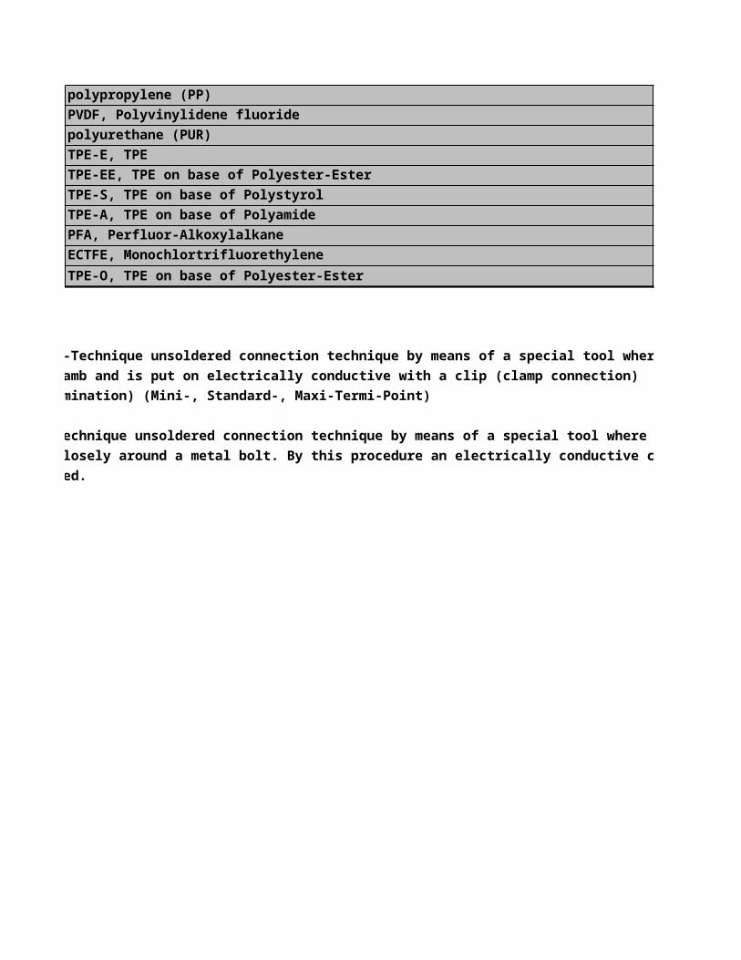
TERMI-POINT:-Technique unsoldered connection technique by means of a special tool where the insulation is stripped o
on a metal jamb and is put on electrically conductive with a clip (clamp connection)
(TERMI → termination) (Mini-, Standard-, Maxi-Termi-Point)
WIRE-WRAP:-Technique unsoldered connection technique by means of a special tool where the stripped-off conductor
is wrapped closely around a metal bolt. By this procedure an electrically conductive connection
is established.

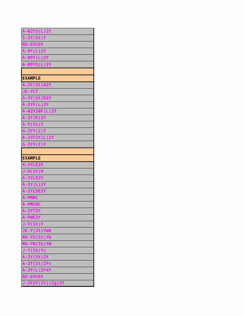
EXAMPLE
A-2YYBY
AB-2YLE2YDB2Y
AJ-2Y(L)2YDBY
AJB-2Y(L)2YDBY
(A)-9Y(K)2Y4Y
G-2YYBY
GJ-YMBY
J-Y(St)Y
(J)-Y(St)Y
JE-Y(St)Y
(JE)-Y(St)Y
J-FY
L-2YYQY
L-Y(St)Y
M-2YC2Y
RD-Y(St)Y
RE-2Y(St)2Y
S-Y(St)Y
A-2YYBY...S
(S)-Y(St)Y
T-Y(St)Y
EXAMPLE
H07V-R
J-H(St)H
A-PMBC
J-Y(St)Y
RD-YU(St)YU
RD-YW(St)YW
PE A-2Y(L)2Y
PE A-02Y(L)2Y
A-02YS(L)2Y
S-3Y(St)Y
RD-6YC6Y
A-9Y(L)2Y
A-09Y(L)2Y
A-09YS(L)2Y
EXAMPLE
A-2Y(St)A2Y
JE-YCY
A-2Y(St)D2Y
A-2YF(L)2Y
A-02YS0F(L)2Y
A-2Y(K)2Y
S-Y(St)Y
G-2YY(Z)Y
A-2YF2Y(L)2Y
G-2YY(Z)Y
EXAMPLE
A-2YLE2Y
J-H(St)H
A-2YLE2Y
A-2Y(L)2Y
A-2YLDE2Y
A-PMBC
A-PMzBC
A-2YT2Y
A-PWE2Y
J-Y(St)Y
JE-Y(St)Ymb
RD-YU(St)YU
RD-YW(St)YW
J-Y(St)Yv
A-2Y(St)2Y
A-2Y(St)2Yv
A-2Y(L)2Y4Y
RD-6YC6YJ-2Y2Y(St)(Zg)2Y
EXAMPLE
A-2Y(L)2YA2Y
A-2Y(L)2YB2Y
A-PMBC

A-2Y(L)2YD2Y
A-2YLEibY
L-2YYQY
A-PLEYBY
A-2YYBY
JE-Y(St)YYv
A-PLE2YB2Y
A-PLEB2Y2Y
A-2Y(L)2Y2Yv
EXAMPLE
...ST III BD
...x 2 x 0,6 BDIMF
L-2Y(C)Y...
...x 2 x 1,2 DM
...x 3 x 0,5 DIMF
J-02YSCeY
...x 2 x 0,9 F
Kx 2,6/9,5
...ST III LG
JE-LiYCY
...x2x0,8STIPCM
2 x 1 x 0,5 Pr
...x 2 x 0,9 ST
...x 2 x 0,6 ST O
...x 2 x 0,9 ST I
...x 2 x 0,6 ST II
...x 2 x 0,6 ST III
...x 2 x 1,2 ST IV
...x 2 x 1,3 ST V
...x 2 x 0,6 ST VI
...x 2 x 1,2 ST I TF
...x 2 x 0,6 VIMF
Y
YV
EXAMPLE
EIB-Bus cable
...(St)H FE180/E30
...(St)H FE180/E90
...(St)H FE180/E30

LiYCY-JB
LiYCY-JZ
L-2YY(Z)YKF40
Limited Oxygen Index (references value for the degree of flame-retardancy)
LiYCY-OB
LiYCY-OZ
JE-Y(St)Y SI
H07V-R
H07V-R
H07V-R
JE-Y(St)Y Z
EXAMPLE
H07V-R
TERMI-POINT:-Technique unsoldered connection technique by means of a special tool where the insulation is stripped o
WIRE-WRAP:-Technique unsoldered connection technique by means of a special tool where the stripped-off conductor
is wrapped closely around a metal bolt. By this procedure an electrically conductive connection

HARMONIZED CABLEHarmonized Identification:The harmonized identifications for cables and wires come to an agreement with the CENELEC-structure (HAR-agreement) are determined by the certification institute. These identifications conform the harmonized standards.The harmonized identification must be visible on the core or the sheath in form of an imprint or embossing,or contained with a three-coloured black-red-yellow protected identification thread of different colour lengths (dimension in cm).
Designation code for harmonized cables
according to DIN VDE 0281/DIN VDE 0282/DIN VDE 0292
Construction reference
1. Identifications of destignationA authorised national standardsH harmonized standards
2.Nominal voltage U1 100V3 300/300V5 300/500V7 450/750V
3.Insulation materialB (EPR)Ethylene-propylene-rubberG (EVA) Ethylene-Vinylacetat-CopolymerN2 (CR) Chloroprene rubber for welding cablesR (NR a./o. SR) Natural a./o. synthetic rubberS (SiR) Silicone rubberV (PVC) Polyvinyl chlorideV2 (PVC) Polyvinyl chloride heat-resistantV3 (PVC) Polyvinyl chloride low-temperatureV4 (PVC) Polyvinyl chloride cross-linkedZ (PE) Polyethylene cross-linked
4.Structural elementsC ScreenQ4 (PA) Additional polyimide core jacketT Additional textile braiding over laid-up coresT6 Additional textile braiding over individual cores
5.Sheath/jacket materialB (EPR) Ethylene-propylene rubberJ Glass fibre braidN (CR) Chloroprene rubberN2 (CR) Chloroprene rubber for welding cablesN4 (CR) Chloroprene rubber heat-resistantQ (PUR) PolyurethaneR (NR a./o. SR) Natural- a./o. synthetic rubberT Textile braidT2 Textile braid with flame retardant compoundV (PVC) Polyvinyl chloride
HOME PAGENEXT PAGE
PREVIOUS PAGE
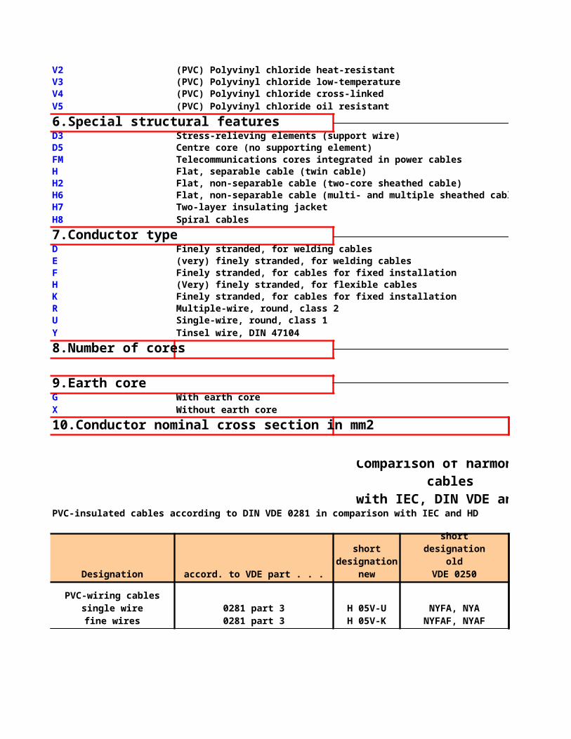
V2 (PVC) Polyvinyl chloride heat-resistantV3 (PVC) Polyvinyl chloride low-temperatureV4 (PVC) Polyvinyl chloride cross-linkedV5 (PVC) Polyvinyl chloride oil resistant
6.Special structural featuresD3 Stress-relieving elements (support wire)D5 Centre core (no supporting element)FM Telecommunications cores integrated in power cablesH Flat, separable cable (twin cable)H2 Flat, non-separable cable (two-core sheathed cable)H6 Flat, non-separable cable (multi- and multiple sheathed cable)H7 Two-layer insulating jacketH8 Spiral cables
7.Conductor typeD Finely stranded, for welding cablesE (very) finely stranded, for welding cablesF Finely stranded, for cables for fixed installationH (Very) finely stranded, for flexible cablesK Finely stranded, for cables for fixed installationR Multiple-wire, round, class 2U Single-wire, round, class 1Y Tinsel wire, DIN 47104
8.Number of cores
9.Earth coreG With earth coreX Without earth core
10.Conductor nominal cross section in mm2
PVC-insulated cables according to DIN VDE 0281 in comparison with IEC and HD
Designation accord. to VDE part . . .
Comparison of harmonized cables
with IEC, DIN VDE and HD
short designation
new
shortdesignation
oldVDE 0250
PVC-wiring cablessingle wirefine wires
0281 part 30281 part 3
H 05V-UH 05V-K
NYFA, NYANYFAF, NYAF

Light PVC-Twin cables 0281 part 5 H 03VH-Y NLYZ
Twin cables 0281 part 5 H 03VH-H NYZ
IEC-definationIEC 227: Polyvinylchloride insulated flexible cables and cords with circular conductors and a rated voltage not exceeding 750 VIEC 245: Rubber insulated flexible cables and cords with circular conductors and a rated voltage not exceeding 750 V
Rubber insulated power cables according to DIN VDE 0282 in comparison with IEC and HD
Designation accord. to VDE part . . .
0282 part 3 H 05SJ-K N2GAFUBraided flexible cord 0282 part 4 H 03RT-F NSA
0282 part 4 H 05RR-F NLH, NMH
0282 part 4 H 05RN-F
0282 part 4 H 07RN-F
PVC-insulated cablessingle wire
multi-stranded wiresfine wires
0281 part 30281 part 30281 part 3
H 07V-UH 07V-RH 07V-K
NYANYA
NYAF
PVC-sheathed cables03VV-F round flat
0281 part 50281 part 5
H 03VV-FH 03VVH2-F
NYLHY rundNYLHY flach
PVC-sheathed cables05VV-F round flat
0281 part 50281 part 5
H 05VV-FH 05VVH2-F
NYMHY rundNYMHY rundNYMHY flach
PVC-Flat-cable 05VV-H6PVC-Flat-cable 07VV-H6
0281 part 4030281 part 404
H 05VVH6-FH 07VVH6-F
NYFLYNYFLY
short designation
new
shortdesignation
oldVDE 0250
Heat-resistant rubberinsulatedcable H 07G
0282 part 70282 part 7
H 07G-UH 07G-K
N4GAN4GAF
Heat-resistant siliconerubbercable
Rubber sheathed flexiblecord 05RR
Polychloroprene sheathedflexible cable 05RN
NYMHo¨ uNYMHo¨ uNYMHo¨ u
Polychloroprene sheathedflexible cable 07RN
NMHo¨ uNSHo¨ u

Designation code for power cablesaccording to DIN VDE 0271/0276Construction reference
1. Identifications of destignation
N DIN VDE standard(N) similar to DIN VDE standard
2.Conductor materialA aluminium conductor– copper conductor
3.Insulating materialsY PVC2X cross-linked PE (XLPE)– impregnated paper
4.Concentric conductor (screen)C concentric conductor of copperCW concentric conductor of copper in waveconal formationCE concentric conductor of copper over each individual coreS screen of copper wiresSE screen of copper wires over each individual coreH conductive layers(F) longitudinally water-proof screen
5.ArmouringB steel tape armouringF armour of galvanized flat steel wiresG counter helix of galvanized steel tapeR armour of galvanized round steel wires
6.Sheath Material
Rubber insulated lift cablewith textile braid 05RT2D5Rubber insulated lift cablewith polychloroprenesheath 05RND5
0282 part 8070282 part 807
H 05RT2D5-FH 05RND5-F
NFLGNFLGC
Rubber insulated lift cablewith textile braid 07RT2D5Rubber insulated lift cablewith polychloroprenesheath 07RND5
0282 part 8080282 part 808
H 07RT2D5-FH 07RND5-F
NFLGNFLGC
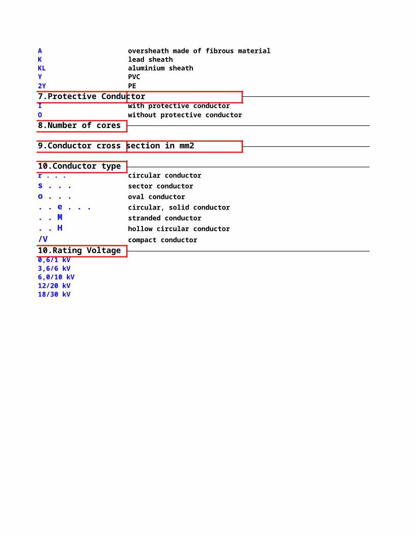
A oversheath made of fibrous materialK lead sheathKL aluminium sheathY PVC2Y PE
7.Protective ConductorI with protective conductorO without protective conductor
8.Number of cores
9.Conductor cross section in mm2
10.Conductor typer . . . circular conductor
s . . . sector conductor
o . . . oval conductor
. . e . . . circular, solid conductor
. . M stranded conductor
. . H hollow circular conductor
/V compact conductor
10.Rating Voltage0,6/1 kV3,6/6 kV6,0/10 kV12/20 kV18/30 kV

HARMONIZED CABLEHarmonized Identification:The harmonized identifications for cables and wires come to an agreement with the CENELEC-structure (HAR-agreement) are determined by the certification institute. These identifications conform the harmonized standards.The harmonized identification must be visible on the core or the sheath in form of an imprint or embossing,or contained with a three-coloured black-red-yellow protected identification thread of different colour lengths (dimension in cm).
H 05 V V5 F 25 G 075

0,5 to 1,0 300/500 HD 21.3 S3
Comparison of harmonized cables
with IEC, DIN VDE and HD
nominalcross-section(mm2)
nominalvoltageU0/U (V)
accordingto HD
comparative
designto IEC
227 IEC 01227 IEC 01

450/750 HD 21.3 S3
0,1 300/300 HD 21.5 S3 227 IEC 41
0,5+0,75 300/300 HD 21.5 S3 227 IEC 42
300/300 HD 21.5 S3
HD 21.5 S3
-- --
IEC 227: Polyvinylchloride insulated flexible cables and cords with circular conductors and a rated voltage not exceeding 750 VIEC 245: Rubber insulated flexible cables and cords with circular conductors and a rated voltage not exceeding 750 V
HD 22.7 S2 --
0,5 to 95 300/500 HD 22.3 S2 245 IEC 030,75 to 1,5 300/500 HD 22.4 S3 245 IEC 51
0,75 to 2,5 300/500 HD 22.4 S3 245 IEC 53
300/500 HD 22.4 S3
450/750 HD 22.4 S3
1,5 to 101,5 to 4001,5 to 240
227 IEC 01227 IEC 01227 IEC 02
0,5+0,750,5+0,75
227 IEC 43227 IEC 43
0,75 to 2,51 to 2,5
0,75300/500300/500
227 IEC 53227 IEC 53
0,75 to 11,5 to 25
300/500450/750
nominalcross-section(mm2)
nominalvoltageU0/U (V)
accordingto HD
comparative
designto IEC
1,5+2,50,5 to 95
450/750
0,75+10,75+10,75
245 IEC 57245 IEC 57245 IEC 57
1,5 to 5001 to 251 to 3001,5+2,5
245 IEC 65245 IEC 66

-- --
-- --
0,750,75
300/500300/500
11
450/750450/750
X

Harmonized Identification:The harmonized identifications for cables and wires come to an agreement with the CENELEC-structure (HAR-agreement) are determined by the certification institute. These identifications conform the harmonized standards.The harmonized identification must be visible on the core or the sheath in form of an imprint or embossing,or contained with a three-coloured black-red-yellow protected identification thread of different colour lengths (dimension in cm).
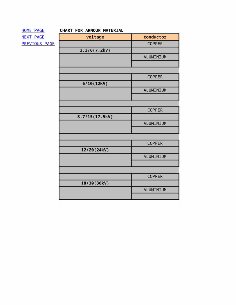
CHART FOR ARMOUR MATERIAL
voltage conductor type of core
COPPER single core
3.3/6(7.2kV) three core
ALUMINIUM single core
three core
COPPER single core
6/10(12kV) three core
ALUMINIUM single core
three core
COPPER single core
8.7/15(17.5kV) three core
ALUMINIUM single core
three core
COPPER single core
12/20(24kV) three core
ALUMINIUM single core
three core
COPPER single core
18/30(36kV) three core
ALUMINIUM single core
three core
HOME PAGE
NEXT PAGE
PREVIOUS PAGE

armour material
aluminium wire
steel wire/steel tape
aluminium wire
steel wire/steel tape
aluminium wire
steel wire/steel tape
aluminium wire
steel wire/steel tape
aluminium wire
steel wire/steel tape
aluminium wire
steel wire/steel tape
aluminium wire
steel wire/steel tape
aluminium wire
steel wire/steel tape
aluminium wire
steel wire/steel tape
aluminium wire
steel wire/steel tape

NYY/power cable
NYY /power cable
VDE 0276 part 603 also IEC 0.6/1 kV
2 1.5 to 2403 1.5 to 2404 1.5 to 2405 1.5 to 25
2XSY,2XS2Y
2XSY,2XS2Y
IEC 502 also VDE BS
3.6/6 kV
1
25 to 5006/10 kV 35 to 500
8.7/15 kV 35 to 50012/20 kV 35 to 50018/30 kV
HOME PAGENEXT PAGE
PREVIOUS PAGE
Type Type designation
Low voltage power cables with PVC insulation and sheath
Standard Rated
voltage
Conductors
Number
Cross sectional area
mm/2 12345
and other
1.5 to 5001.5 to 2401.5 to 2401.5 to 2401.5 to 25
and other
Type Type designation
Middle voltage power cables with XLPE insulation.
Standard Rated
voltage
Conductors
Number
Cross sectional area
mm/2
50 to 500

A2XSY,A2XS2Y
A2XSY,A2XS2Y
IEC 502 also VDE BS
3.6/6 kV
1
25 to 5006/10 kV 35 to 500
8.7/15 kV 35 to 50012/20 kV 35 to 50018/30 kV
2XS(F)2Y
2XS(F)2Y
IEC 502
3.6/6 kV
1
25 to 5006/10 kV 35 to 500
8.7/15 kV 35 to 50012/20 kV 35 to 50018/30 kV
A2XS(F)2YType
Type Type designation
Middle voltage power cables with XLPE insulation.
Standard Rated
voltage
Conductors
Number
Cross sectional area
mm/2
50 to 500
Type Type designation
Middle voltage power cables with XLPE insulation. Longitudinal water sealed.
Standard Rated
voltage
Conductors
Number
Cross sectional area
mm/2
50 to 500
Type designation

A2XS(F)2Y
IEC 502
3.6/6 kV
1
25 to 5006/10 kV 35 to 500
8.7/15 kV 35 to 50012/20 kV 35 to 50018/30 kV
2XSEY
2XSEY
IEC 502 also VDE BS
3.6/6 kV
3
25 to 2406/10 kV 35 to 240
8.7/15 kV 35 to 18512/20 kV 35 to 18518/30 kV
A2XSEY
A2XSEY
Middle voltage power cables with XLPE insulation. Longitudinal water sealed.
Standard Rated
voltage
Conductors
Number
Cross sectional area
mm/2
50 to 500
Type Type designation
Middle voltage power cables with XLPE insulation.
Standard Rated
voltage
Conductors
Number
Cross sectional area
mm/2
50 to 150
Type Type designation
Middle voltage power cables with XLPE insulation.

A2XSEY
IEC 502 also VDE BS
3.6/6 kV
3
25 to 2406/10 kV 35 to 240
8.7/15 kV 35 to 18512/20 kV 35 to 18518/30 kV
2XSEH
2XSEH
IEC 502 IEC 332-3 cat A 3.6/6 kV
325 to 240
6/10 kV
A2XSEH
A2XSEH
Middle voltage power cables with XLPE insulation.
Standard Rated
voltage
Conductors
Number
Cross sectional area
mm/2
50 to 150
Type Type designation
Middle voltage power cables with XLPE insulation with improved characteristics in case of fire.
Standard Rated
voltage
Conductors
Number
Cross sectional area
mm/2
35 to 240
Type Type designation
Middle voltage power cables with XLPE insulation with improved characteristics in case of fire.

A2XSEH
IEC 502 IEC 332-3 cat A 3.6/6 kV
325 to 240
6/10 kV
NAYY
NAYY
VDE 0276 part 603 also IEC 0.6/1 kV
1 25 to 5002 25 to 2403 25 to 2404 25 to 2405 25 to 95
NYY/control cable
NYY /control cable/
VDE 0271 also IEC 0.6/1 kV
7 to 19 1.5,2.5,420 to 37 1.5,2.5
NYCY/power cable
NYCY /power cable/
Middle voltage power cables with XLPE insulation with improved characteristics in case of fire.
Standard Rated
voltage
Conductors
Number
Cross sectional area
mm/2
35 to 240
Type Type designation
Low voltage power cables with PVC insulation and sheath
Standard Rated
voltage
Conductors
Number
Cross sectional area
mm/2
and other
Type Type designation
Low voltage control cables with PVC insulation and sheath
Standard Rated
voltage
Conductors
Number
Cross sectional area
mm/2
and other
Type Type designation
Low voltage power cables with PVC insulation and concentric protective conductor

NYCY /power cable/
VDE 0276 part 603 also IEC 0.6/1 kV
1 to 5 1.5 to 240and other
NAYCY
NAYCY
VDE 0276 part 603 also IEC 0.6/1 kV
1 to 5 25 to 240and other
NYCY/control cable
NYCY /control cable/
VDE 0271/86 also IEC 502 0.6/1 kV
7 to 19 1.5,2.5,420 to 37 1.5,2.5
YBY
Low voltage power cables with PVC insulation and concentric protective conductor
Standard Rated
voltage
Conductors
Number
Cross sectional area
mm/2
and other
Type Type designation
Low voltage power cables with PVC insulation and concentric protective conductor
Standard Rated
voltage
Conductors
Number
Cross sectional area
mm/2
and other
Type Type designation
Low voltage control cables with PVC insulation and concentric conductor
Standard Rated
voltage
Conductors
Number
Cross sectional area
mm/2
and other
Type Type designation
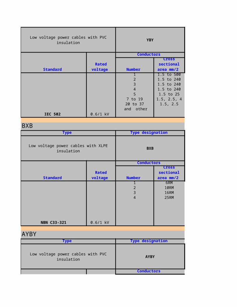
Low voltage power cables with PVC insulation YBY
IEC 502 0.6/1 kV
1 1.5 to 5002 1.5 to 2403 1.5 to 2404 1.5 to 2405 1.5 to 25
7 to 19 1.5, 2.5, 420 to 37 1.5, 2.5
BXB
Low voltage power cables with XLPE insulation BXB
NBN C33-321 0.6/1 kV
1 6RM2 10RM3 16RM4 25RM
AYBY
Low voltage power cables with PVC insulation AYBY
Standard Rated
voltage
Conductors
Number
Cross sectional area
mm/2
and other
Type Type designation
Standard Rated
voltage
Conductors
Number
Cross sectional area
mm/2
Type Type designation
Standard Rated
voltage
Conductors
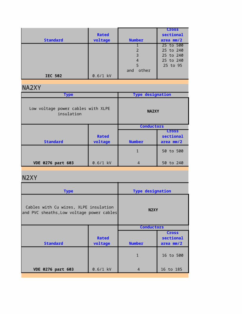
IEC 502 0.6/1 kV
1 25 to 5002 25 to 2403 25 to 2404 25 to 2405 25 to 95
NA2XY
Low voltage power cables with XLPE insulation NA2XY
VDE 0276 part 603 0.6/1 kV
1 50 to 500
N2XY
N2XY
VDE 0276 part 603 0.6/1 kV
1 16 to 500
16 to 185
Standard Rated
voltage Number
Cross sectional area
mm/2
and other
Type Type designation
Standard Rated
voltage
Conductors
Number
Cross sectional area
mm/2
4 50 to 240
Type Type designation
Cables with Cu wires, XLPE insulation and PVC sheaths,Low voltage power cables
Standard Rated
voltage
Conductors
Number
Cross sectional area
mm/2
4
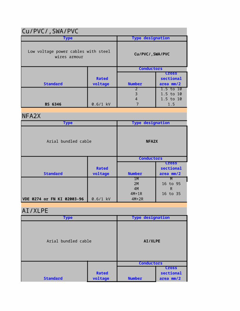
Cu/PVC/,SWA/PVC
Low voltage power cables with steel wires armour Cu/PVC/,SWA/PVC
BS 6346 0.6/1 kV
2 1.5 to 103 1.5 to 104 1.5 to 10
NFA2X
Arial bundled cable NFA2X
VDE 0274 or FN KI 02003-96 0.6/1 kV
1M M2M 16 to 954M R
4M+1R 16 to 35
AI/XLPE
Arial bundled cable AI/XLPE
Type Type designation
Standard Rated
voltage
Conductors
Number
Cross sectional area
mm/2
7 1.5
Type Type designation
Standard Rated
voltage
Conductors
Number
Cross sectional area
mm/2
4M+2R
Type Type designation
Standard Rated
voltage
Conductors
Number
Cross sectional area
mm/2
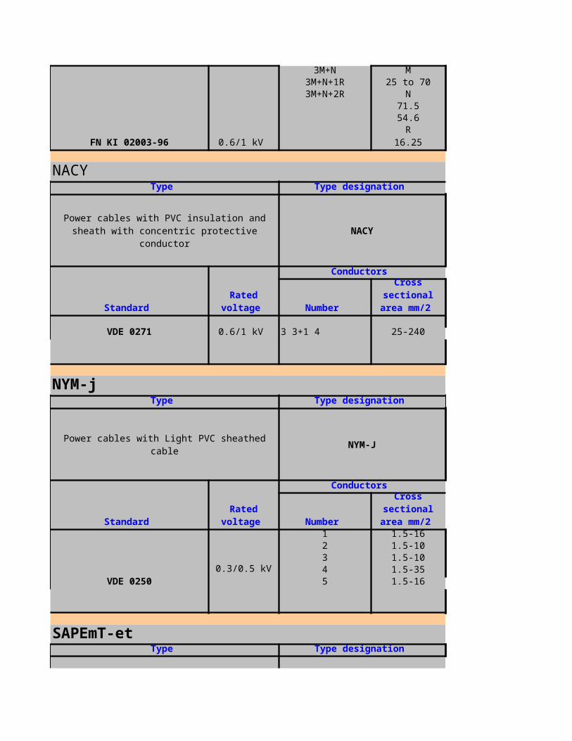
FN KI 02003-96 0.6/1 kV
3M+N M3M+N+1R 25 to 703M+N+2R N
71.554.6
R
NACY
NACY
VDE 0271 0.6/1 kV 3 3+1 4 25-240
NYM-j
Power cables with Light PVC sheathed cable NYM-J
VDE 0250
1 1.5-162 1.5-103 1.5-104 1.5-355 1.5-16
SAPEmT-et
Power cables with PE insulation and PVC sheath SAPEmT-et
16.25
Type Type designation
Power cables with PVC insulation and sheath with concentric protective conductor
Standard Rated
voltage
Conductors
Number
Cross sectional area
mm/2
Type Type designation
Standard Rated
voltage
Conductors
Number
Cross sectional area
mm/2
0.3/0.5 kV
Type Type designation
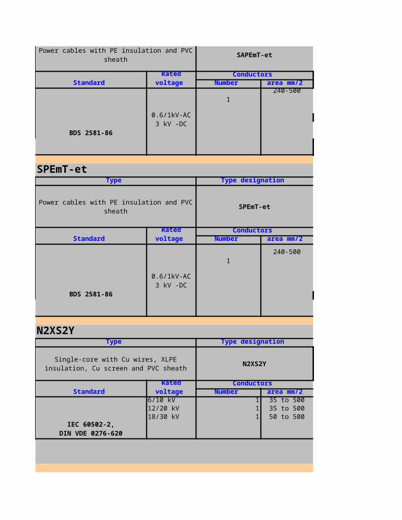
Power cables with PE insulation and PVC sheath SAPEmT-et
BDS 2581-86
1
SPEmT-et
Power cables with PE insulation and PVC sheath SPEmT-et
BDS 2581-86
1
N2XS2Y
N2XS2Y
6/10 kV 1 35 to 50012/20 kV 1 35 to 50018/30 kV 1 50 to 500
Standard Rated
voltage Conductors
Number
Cross sectional area
mm/2
0.6/1kV-AC3 kV -DC
240-500
Type Type designation
Standard Rated
voltage Conductors
Number
Cross sectional area
mm/2
0.6/1kV-AC3 kV -DC
240-500
Type Type designation
Single-core with Cu wires, XLPE insulation, Cu screen and PVC sheath
Standard Rated
voltage Conductors
Number
Cross sectional area
mm/2
IEC 60502-2,DIN VDE 0276-620

N2XS(F)2Y
N2XS(F)2Y
6/10 kV 1 35 to 50012/20 kV 1 35 to 50018/30 kV 1 50 to 500
N2XSEY, 2XSEY
N2XSEY, 2XSEY
3.6/6kV 3 35 to 3006/10kV 3 35 to 300
12/20kV 3 35 to 30018/30kV 3 35 to 300
N2XSY
N2XSY
6/10 kV 1 35 to 50012/20 kV 1 35 to 50018/30 kV 1 50 to 500
Type Type designation
Single-core with Cu wires, XLPE insulation, Cu screen and PVC sheath
Standard Rated
voltage Conductors
Number
Cross sectional area
mm/2
IEC 60502-2,DIN VDE 0276-620
Type Type designation
Three-core with Cu wires XLPE insulation, Cu screen and PVC sheath
Standard Rated
voltage Conductors
Number
Cross sectional area
mm/2
IEC 60502-2DIN VDE 0276-620
Type Type designation
Single-core with Cu wires, XLPE insulation, Cu screen and PVC sheath
Standard Rated
voltage Conductors
Number
Cross sectional area
mm/2
IEC 60502-2DIN VDE 0276-620

NA2XS2Y
NA2XS2Y
6/10 kV 1 35 to 50012/20 kV 1 35 to 50018/30 kV 1 50 to 500
NA2XS(F)2Y
NA2XS(F)2Y
6/10 kV 1 35 to 50012/20 kV 1 35 to 50018/30 kV 1 50 to 500
NA2XSEY,A2XSEY
NA2XSEY,A2XSEY
3.6/6kV 3 35 to 3006/10kV 3 35 to 300
12/20kV 3 50 to 300
Type Type designation
Single-core with Al wires, XLPE insulation, Cu screen and PVC sheath
Standard Rated
voltage Conductors
Number
Cross sectional area
mm/2
IEC 60502-2DIN VDE 0276-620
Type Type designation
Single-core with Al wires, XLPE insulation, Cu screen and PVC sheath
Standard Rated
voltage Conductors
Number
Cross sectional area
mm/2
IEC 60502-2DIN VDE 0276-620
Type Type designation
Three-core with Al wires XLPE insulation, Cu screen and PVC sheath
Standard Rated
voltage
Conductors
Number
Cross sectional area
mm/2
IEC 60502-2DIN VDE 0276-620
18/30kV 3
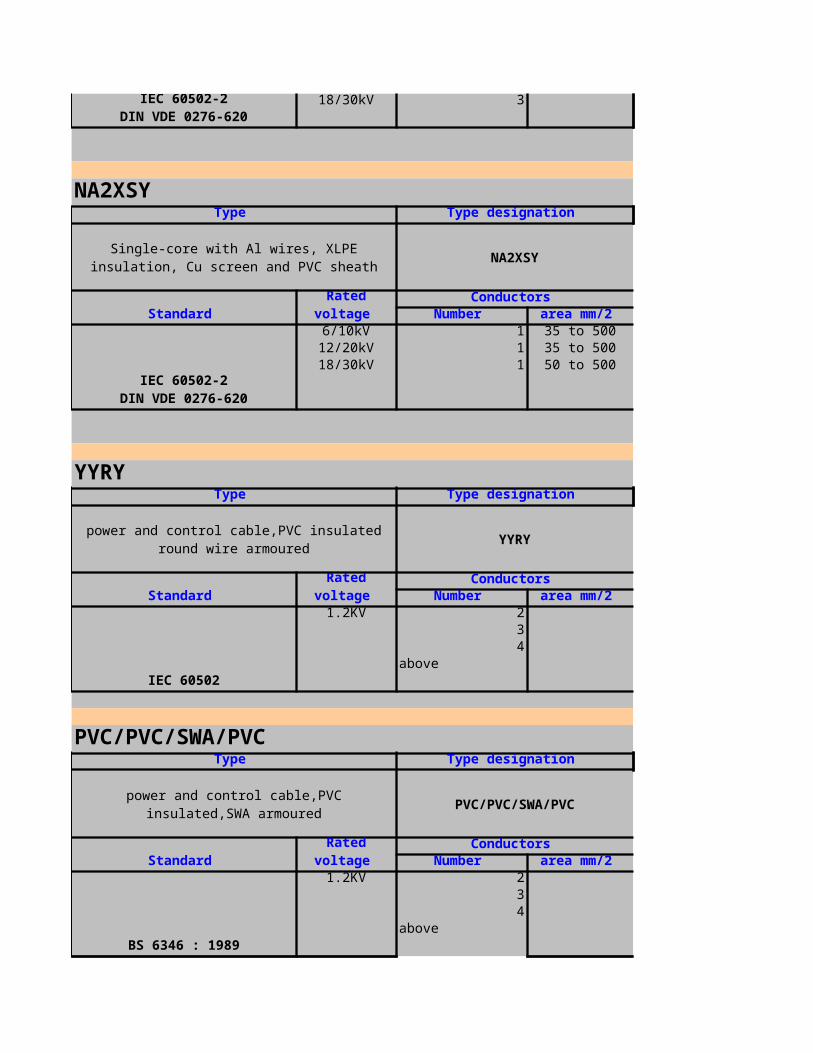
NA2XSY
NA2XSY
6/10kV 1 35 to 50012/20kV 1 35 to 50018/30kV 1 50 to 500
YYRY
YYRY
IEC 60502
1.2KV 234
above
PVC/PVC/SWA/PVC
PVC/PVC/SWA/PVC
BS 6346 : 1989
1.2KV 234
above
IEC 60502-2DIN VDE 0276-620
Type Type designation
Single-core with Al wires, XLPE insulation, Cu screen and PVC sheath
Standard Rated
voltage Conductors
Number
Cross sectional area
mm/2
IEC 60502-2DIN VDE 0276-620
Type Type designation
power and control cable,PVC insulated round wire armoured
Standard Rated
voltage Conductors
Number
Cross sectional area
mm/2
Type Type designation
power and control cable,PVC insulated,SWA armoured
Standard Rated
voltage Conductors
Number
Cross sectional area
mm/2
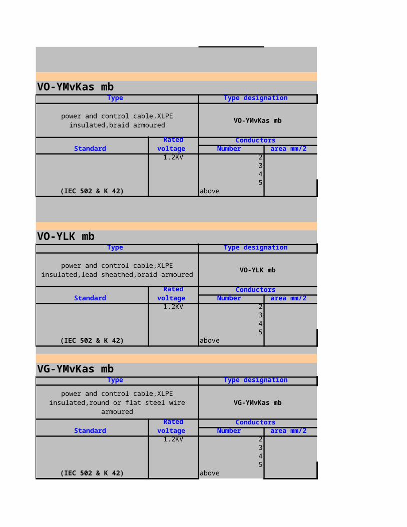
VO-YMvKas mb
VO-YMvKas mb
(IEC 502 & K 42)
1.2KV 2345
above
VO-YLK mb
VO-YLK mb
(IEC 502 & K 42)
1.2KV 2345
above
VG-YMvKas mb
VG-YMvKas mb
(IEC 502 & K 42)
1.2KV 2345
above
Type Type designation
power and control cable,XLPE insulated,braid armoured
Standard Rated
voltage Conductors
Number
Cross sectional area
mm/2
Type Type designation
power and control cable,XLPE insulated,lead sheathed,braid armoured
Standard Rated
voltage Conductors
Number
Cross sectional area
mm/2
Type Type designation
power and control cable,XLPE insulated,round or flat steel wire armoured
Standard Rated
voltage Conductors
Number
Cross sectional area
mm/2
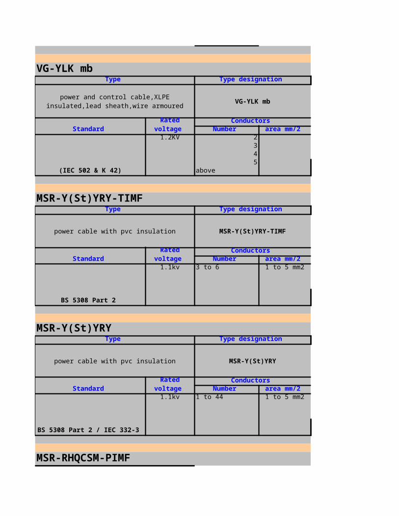
VG-YLK mb
VG-YLK mb
(IEC 502 & K 42)
1.2KV 2345
above
MSR-Y(St)YRY-TIMF
power cable with pvc insulation MSR-Y(St)YRY-TIMF
BS 5308 Part 2
1.1kv 3 to 6 1 to 5 mm2
MSR-Y(St)YRY
power cable with pvc insulation MSR-Y(St)YRY
BS 5308 Part 2 / IEC 332-3
1.1kv 1 to 44 1 to 5 mm2
MSR-RHQCSM-PIMF
Type Type designation
power and control cable,XLPE insulated,lead sheath,wire armoured
Standard Rated
voltage Conductors
Number
Cross sectional area
mm/2
Type Type designation
Standard Rated
voltage Conductors
Number
Cross sectional area
mm/2
Type Type designation
Standard Rated
voltage Conductors
Number
Cross sectional area
mm/2

power cable with epr insulation MSR-RHQCSM-PIMF
1.1kv 3 X 2 1 to 5 mm2
MSR-02YS(St)Y-PIMF
power cable with PE insulation MSR-02YS(St)Y-PIMF
1.1kv 8 x 2 0 to 5 mm2
MSR-2Y(L)2YY
power cable with PE insulation MSR-2Y(L)2YY
BS 6883 / IEC 331 / IEC 332-3
1.1kv 24 X 2 1 to 3 mm2
MSR-Y(St)YBY
power cable with PVC insulation MSR-Y(St)YBY
Type Type designation
Standard Rated
voltage Conductors
Number
Cross sectional area
mm/2
BS 6883 / IEC 331 / IEC 332-3
Type Type designation
Standard Rated
voltage Conductors
Number
Cross sectional area
mm/2
BS 6883 / IEC 331 / IEC 332-3
Type Type designation
Standard Rated
voltage Conductors
Number
Cross sectional area
mm/2
Type Type designation
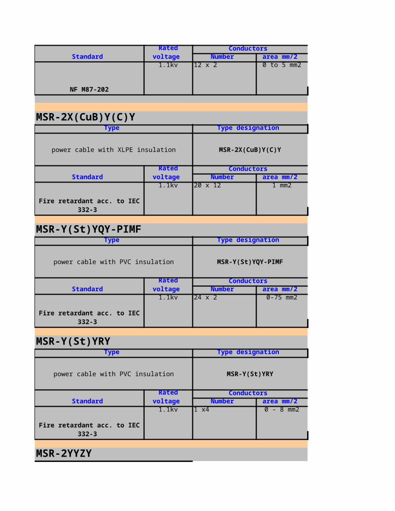
NF M87-202
1.1kv 12 x 2 0 to 5 mm2
MSR-2X(CuB)Y(C)Y
power cable with XLPE insulation MSR-2X(CuB)Y(C)Y
Fire retardant acc. to IEC 332-3
1.1kv 20 x 12 1 mm2
MSR-Y(St)YQY-PIMF
power cable with PVC insulation MSR-Y(St)YQY-PIMF
Fire retardant acc. to IEC 332-3
1.1kv 24 x 2 0-75 mm2
MSR-Y(St)YRY
power cable with PVC insulation MSR-Y(St)YRY
Fire retardant acc. to IEC 332-3
1.1kv 1 x4 0 - 8 mm2
MSR-2YYZY
Standard Rated
voltage Conductors
Number
Cross sectional area
mm/2
Type Type designation
Standard Rated
voltage Conductors
Number
Cross sectional area
mm/2
Type Type designation
Standard Rated
voltage Conductors
Number
Cross sectional area
mm/2
Type Type designation
Standard Rated
voltage Conductors
Number
Cross sectional area
mm/2

MSR-2YYZY
VDE 0816 Part 2
1.1kv 30 x 2 0 - 8 mm2
MSR-2YYZY
MSR-2YYZY
VDE 0817
1.1kv 12 x 2 0-5 mm2
MSR-2Y(St)H
MSR-2Y(St)H
Fire retardant acc. to IEC 332-3
1.1kv 8 X 2 1 mm2
MSR-2Y(St)H ... Bd
MSR-2Y(St)H ... Bd
Fire retardant acc. to IEC 332-3
1.1kv 8 X 2 0 - 5mm2
Type Type designation
power cable with PE insulation,Cable type :G-2YY(Z)Y+ER
Standard Rated
voltage Conductors
Number
Cross sectional area
mm/2
Type Type designation
power cable with PE insulation,Cable type :L-2YYQY
Standard Rated
voltage Conductors
Number
Cross sectional area
mm/2
Type Type designation
power cable with PE insulation
Standard Rated
voltage Conductors
Number
Cross sectional area
mm/2
Type Type designation
power cable with PE insulation
Standard Rated
voltage Conductors
Number
Cross sectional area
mm/2

Fire retardant acc. to IEC 332-3
MSR-RH(C)EVA-PIMF
MSR-RH(C)EVA-PIMF
1.1kv 2 X 2 0 -75mm2
MSR-2XY(C)Y
MSR-2XY(C)Y
IEC 92-3 / IEC 332-3
1.1kv 7 1 - 5 mm2
MSR-Y(St)Y
power cable with PVC insulation MSR-Y(St)Y
--
1.1kv 12 1mm2
MSR-2X(L)2Y
MSR-2X(L)2Y
Type Type designation
power cable with EPR insulation,cable type:BFOU
Standard Rated
voltage Conductors
Number
Cross sectional area
mm/2
IEC 92-3 / IEC 331 / IEC 332-3 / EC 754-2
Type Type designation
power cable with XLPE insulation,cable type:TPOP
Standard Rated
voltage Conductors
Number
Cross sectional area
mm/2
Type Type designation
Standard Rated
voltage Conductors
Number
Cross sectional area
mm/2
Type Type designation
power cable with XLPE insulation,Cable type : (N)2X (L)2Y
Standard Rated
voltage Conductors

adapted to VDE 0276 Part 603
1.1kv 14 1 - 5 mm2
MSR-2Y(L)2YKYRY
power cable with PE insulation MSR-2Y(L)2YKYRY
VDE 0816 / IEC 332-3
1.1kv 1 X 4 0 - 8 mm2
MSR-2Y(C)Y-PIMF
power cable with PE insulation MSR-2Y(C)Y-PIMF
1.1kv 10 X 2 0 to 5 mm2
TYPE DESIGNATION STANDARD CONDUCTORS
CU/XLPE/CWS/PVC BS 6622:1999 3.8/6.6(7.2) COPPER
CU/XLPE/CTS/PVC BS 6622:1999 6.35/11(12) COPPER
CU/XLPE/CWS/MDPE BS 6622:1999 8.7/15(17.5) COPPER
CU/XLPE/CTS/MDPE BS 6622:1999 12.7/22(24) COPPER
AL/XLPE/CWS/PVC BS 6622:1999 19/33(36) ALUMINIUM
AL/XLPE/CTS/PVC BS 6622:1999 ALUMINIUM
AL/XLPE/CWS/MDPE BS 6622:1999 ALUMINIUM
AL/XLPE/CTS/MDPE BS 6622:1999 ALUMINIUM
TYPE DESIGNATION STANDARD CONDUCTORS
Standard Rated
voltage Number
Cross sectional area
mm/2
Type Type designation
Standard Rated
voltage Conductors
Number
Cross sectional area
mm/2
Type Type designation
Standard Rated
voltage Conductors
Number
Cross sectional area
mm/2
RATEDVOLTAGE POSSIBLE
RATEDVOLTAGE POSSIBLE
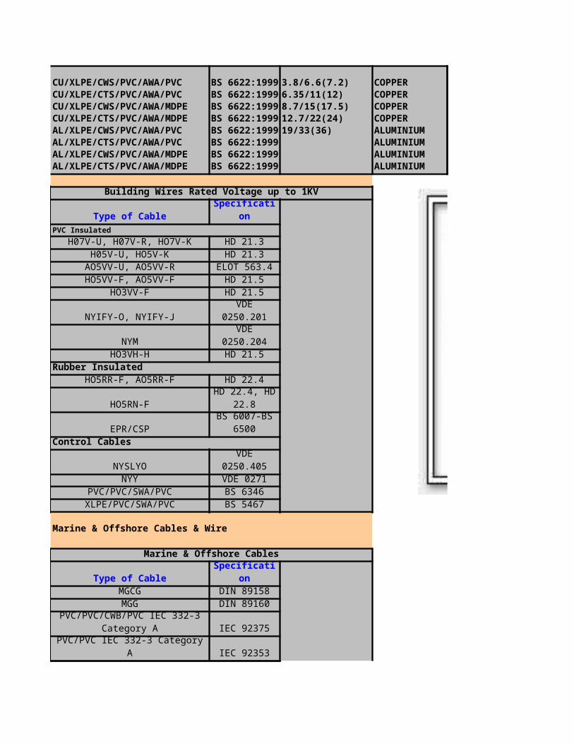
CU/XLPE/CWS/PVC/AWA/PVC BS 6622:1999 3.8/6.6(7.2) COPPERCU/XLPE/CTS/PVC/AWA/PVC BS 6622:1999 6.35/11(12) COPPERCU/XLPE/CWS/PVC/AWA/MDPE BS 6622:1999 8.7/15(17.5) COPPERCU/XLPE/CTS/PVC/AWA/MDPE BS 6622:1999 12.7/22(24) COPPERAL/XLPE/CWS/PVC/AWA/PVC BS 6622:1999 19/33(36) ALUMINIUMAL/XLPE/CTS/PVC/AWA/PVC BS 6622:1999 ALUMINIUMAL/XLPE/CWS/PVC/AWA/MDPE BS 6622:1999 ALUMINIUMAL/XLPE/CTS/PVC/AWA/MDPE BS 6622:1999 ALUMINIUM
Building Wires Rated Voltage up to 1KV
Type of Cable SpecificationPVC Insulated
H07V-U, H07V-R, HO7V-K HD 21.3H05V-U, HO5V-K HD 21.3
AO5VV-U, AO5VV-R ELOT 563.4HO5VV-F, AO5VV-F HD 21.5
HO3VV-F HD 21.5
NYIFY-O, NYIFY-J VDE 0250.201
NYM VDE 0250.204HO3VH-H HD 21.5
Rubber InsulatedHO5RR-F, AO5RR-F HD 22.4
HO5RN-F
EPR/CSPControl Cables
NYSLYO VDE 0250.405NYY VDE 0271
PVC/PVC/SWA/PVC BS 6346XLPE/PVC/SWA/PVC BS 5467
Marine & Offshore Cables & Wire
Marine & Offshore Cables
Type of Cable SpecificationMGCG DIN 89158MGG DIN 89160
IEC 92375
PVC/PVC IEC 332-3 Category A IEC 92353
HD 22.4, HD 22.8
BS 6007-BS 6500
PVC/PVC/CWB/PVC IEC 332-3 Category A

IEC 92353
IEC 92353
IEC 92353
BS 6883
BS 6883
Power Cables
Power Cables Rated Voltage up to 1KV
Type of Cable SpecificationPVC Insulated
NYY, NAYY VDE 0271NYCWY VDE 0271
PVC/SWA/PVC BS 6346XLPE Insulated
XLPE/PVC/SWA/PVC BS 5467XLPE/PVC IEC 502
U-1000 R2V NF C 32-321Rubber Insulated
NSSHOU VDE 0250.812HO7RN-F, AO7RN-7 HD 22.4HO1N2-D, HO1N2-E HD 22.6
EPR/CSP BS 6007
NSGAFOU VDE 0250.602
NTSWOU VDE 0250.813Halogen Free Cables
XLPE/LSF/SWA/LSF BS 6724
VDE 0266.3
VDE 0266.2
Power Cables Above 1KV
Type of Cable SpecificationXLPE/PVC/SWA/PVC 3.3 KV BS 5467
XLPE/PVC 6.6-11-15-22-33 KV
PVC/PVC/GSWB/PVC IEC 332-3 Category A
PVC/PVC/CWB/PVC IEC 332-3 Category A
PVC/PVC/CWB/PVC IEC 332-3 Category A
PVC/PVC/CWB/PVC IEC 332-3 Category A
PVC/PVC/CWB/PVC IEC 332-3 Category A
NHXHX, NHXCHX (FE 180 and E30 or E90)
N2XH, N2XCH (FE 180 and E30 or E90)
BS 6622 or IEC 502
XLPE/PVC/SWA/PVC 6.6-11-15-22-33 KV
BS 6622 or IEC 502

N2XSY, NA2XSY 6-10-20-30 KV VDE 276.620
N2XSY, NA2XS2Y 6-10-20-30 KV VDE 276.620
NSGAFOU 3-6 KV VDE 0250 602
VDE 0250.813
H05V-U
Single-core non-sheathed cable H05V-U
VDE 0281 also IEC BS 300/500 V 1 0.5 to 1
H05V-K
Single-core non-sheathed cable H05V-K
VDE 0281 also IEC BS 300/500 V 1 0.5 to 1
H05S-K
Heat resistant flexible conductor H05S-K
NTSCGEWOU 3-6-10-15-20-30 KV
N2XS (FL) 2Y, NA2XS (FL) 2Y 69-110-132-150 KV
Type Type designation
Standard Rated
voltage
Conductors
Number
Cross sectional area
mm/2
Type Type designation
Standard Rated
voltage
Conductors
Number
Cross sectional area
mm/2
Type Type designation
Standard Rated
voltage
Conductors
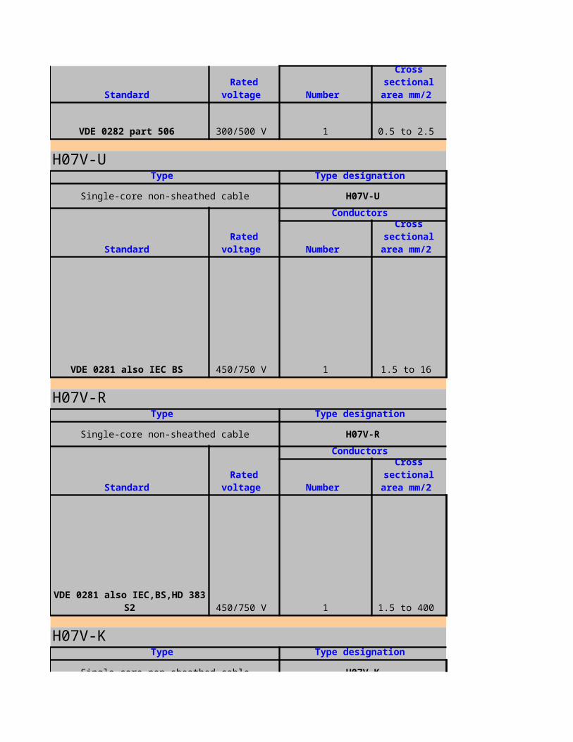
VDE 0282 part 506 300/500 V 1 0.5 to 2.5
H07V-U
Single-core non-sheathed cable H07V-U
VDE 0281 also IEC BS 450/750 V 1 1.5 to 16
H07V-R
Single-core non-sheathed cable H07V-R
450/750 V 1 1.5 to 400
H07V-K
Single-core non-sheathed cable H07V-K
Standard Rated
voltage Number
Cross sectional area
mm/2
Type Type designation
Standard Rated
voltage
Conductors
Number
Cross sectional area
mm/2
Type Type designation
Standard Rated
voltage
Conductors
Number
Cross sectional area
mm/2
VDE 0281 also IEC,BS,HD 383 S2
Type Type designation

Single-core non-sheathed cable H07V-K
VDE 0281 also IEC BS 450/700 V 1 1.5 to 240
NYIFY
Flat building wires NYIFY
VDE 0250 220/380 V
2 1.5 to 43 1.5 to 44 1.5 to 2.5
NYM
Light PVC sheathed cable NYM
VDE 250 part 204 300/500 V
1 1.5 to 162 1.5 to 103 1.5 to 104 1.5 to 35
NHXMH
Standard Rated
voltage
Conductors
Number
Cross sectional area
mm/2
Type Type designation
Standard Rated
voltage
Conductors
Number
Cross sectional area
mm/2
5 1.5 to 2.5
Type Type designation
Standard Rated
voltage
Conductors
Number
Cross sectional area
mm/2
5 1.5 to 16
Type Type designation

NHXMH
VDE 250 part 214 300/500 V
1 1.5 to 162 1.5 to 43 1.5 to 354 1.5 to 355 1.5 to 35
NYBUY
Lead covered PVC sheathed cable NYBUY
VDE 0250 300/500 V
2 1.5 to 353 1.5 to 354 1.5 to 35
H03VV-F
Light PVC sheathed cord H03VV-F
VDE 0281 also IEC, BS, NFC 300/300 V
2 0.5, 0.753 0.5, 0.75
H03VV-FStandard: VDE 0281 Part 5, HD21.5S3IEC 227-5
Halogen free plastic sheathed cables with improved characteristics in case of fire
Standard Rated
voltage
Conductors
Number
Cross sectional area
mm/2
7 1.2, 2.5
Type Type designation
Standard Rated
voltage
Conductors
Number
Cross sectional area
mm/2
5 1.2 to 6
Type Type designation
Standard Rated
voltage
Conductors
Number
Cross sectional area
mm/2
4 0.5, 0.75

Rating: 70 , 300 / 300V℃No.of Conductor Conductor
No.of Cores
Section Area Contruction Nom.Thick.
(No./mm) (mm)2 0.5 29 / 0.15 0.52 0.75 43 / 0.15 0.53 0.5 29 / 0.15 0.53 0.75 43 / 0.15 0.5
Marking: H03VV-F (VDE) No. C X Sq.mm KEMA-KEUR CHAU'S BSI
H03VVH2-F
Light PVC sheathed cord H03VVH2-F
VDE 0281 also IEC, BS, NFC 300/300 V
2 0.5, 0.753 0.5, 0.75
H03VVH2-FStandard: VDE 0281 Part 5, HD21.5S3IEC 227-5Rating: 70 , 300 / 300V℃
No.of Conductor Conductor
No.of Cores
Section Area Contruction Nom.Thick.
(No./mm) (mm)2 0.5 29 / 0.15 0.52 0.75 43 / 0.15 0.5
Marking: H03VVH2-F (VDE) No. C X Sq.mm KEMA-KEUR CHAU'S GOST (RUSSIA) HO3VVH2-F 60227 IEC 52 NO. C X Sq.mm 300 / 300V GOST (Marking) TH02 CHAU'S
H05VV-F
Ordinary PVC sheathed cord H05VV-F
VDE 0281 also IEC, BS, NFC 300/500 V
2 0.75 to 4.03 0.75 to 4.04 0.75 to 4.0
(mm2)
Type Type designation
Standard Rated
voltage
Conductors
Number
Cross sectional area
mm/2
4 0.5, 0.75
(mm2)
Type Type designation
Standard Rated
voltage
Conductors
Number
Cross sectional area
mm/2
5 0.75 to 4.0

H05VV-FStandard: VDE 0281 Part 5, HD21.5S3IEC 227-5Rating: 70 , 300 / 500V℃
No.of Conductor Conductor InsulationSection Area Contruction Nom.Thick.
(No./mm) (mm)2 0.75 43 / 0.15 0.62 1 32 / 0.2 0.62 1.25 40 / 0.2 0.82 1.5 30 / 0.253 0.72 2.5 50 / 0.253 0.83 0.75 43 / 0.15 0.63 1 32 / 0.2 0.63 1.25 40 / 0.2 0.83 1.5 30 / 0.253 0.73 2.5 50 / 0.253 0.8
Marking: H05VV-F(VDE) NO. C X Sq.mm KEMA-KEUR CHAU'S BSI
H05VVH2-F
Ordinary PVC sheathed cord H05VVH2-F
VDE 0281 also IEC, BS, NFC 300/500 V
2 0.75 to 4.03 0.75 to 4.04 0.75 to 4.0
H05VVH2-FStandard: VDE 0281 Part 5, HD21, 5S3IEC 227-5Rating: 70 , 300 / 500V℃No.of Conductor Conductor
No.of Cores
Section Area Contruction Nom.Thick.
(No./mm) (mm)2 0.75 43 / 0.15 0.62 1 32 / 0.2 0.6
Marking: HO5VVH2-F( VDM) No. C Size Sq.mm KEMA-KEUR CHAU'S GOST (RUSSIA) H05VVH2-F 60227 IEC 53 No. C X Sq.mm 300 / 500V GOST( Marking) TH02 CHAU'S
H03VH-Y
(mm2)
Type Type designation
Standard Rated
voltage
Conductors
Number
Cross sectional area
mm/2
5 0.75 to 4.0
(mm2)
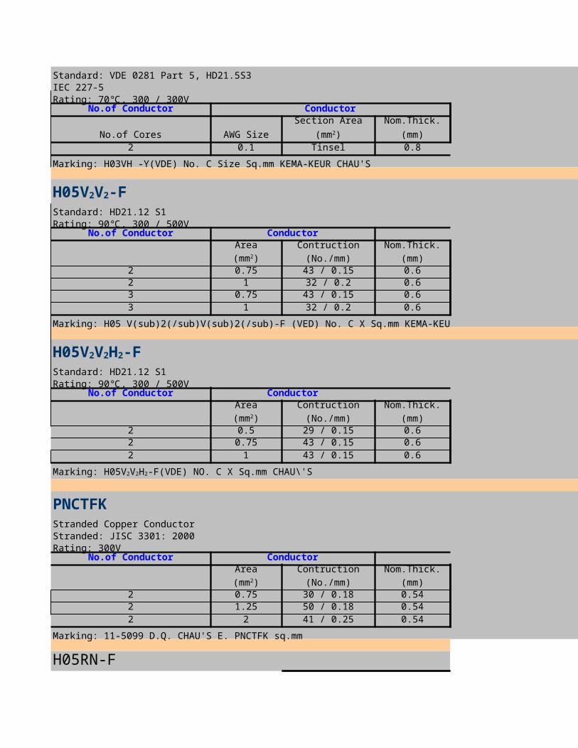
Standard: VDE 0281 Part 5, HD21.5S3IEC 227-5Rating: 70 , 300 / 300V℃
No.of Conductor Conductor
No.of Cores AWG Size
Section Area Nom.Thick.
(mm)2 0.1 Tinsel 0.8
Marking: H03VH -Y(VDE) No. C Size Sq.mm KEMA-KEUR CHAU'S
Standard: HD21.12 S1Rating: 90 , 300 / 500V℃
No.of Conductor Conductor InsulationSection Area Contruction Nom.Thick.
(No./mm) (mm)2 0.75 43 / 0.15 0.62 1 32 / 0.2 0.63 0.75 43 / 0.15 0.63 1 32 / 0.2 0.6
Marking: H05 V(sub)2(/sub)V(sub)2(/sub)-F (VED) No. C X Sq.mm KEMA-KEUR CHAU\'S
Standard: HD21.12 S1Rating: 90 , 300 / 500V℃
No.of Conductor Conductor InsulationSection Area Contruction Nom.Thick.
(No./mm) (mm)2 0.5 29 / 0.15 0.62 0.75 43 / 0.15 0.62 1 43 / 0.15 0.6
PNCTFKStranded Copper ConductorStranded: JISC 3301: 2000Rating: 300V
No.of Conductor Conductor InsulationSection Area Contruction Nom.Thick.
(No./mm) (mm)2 0.75 30 / 0.18 0.542 1.25 50 / 0.18 0.542 2 41 / 0.25 0.54
Marking: 11-5099 D.Q. CHAU'S E. PNCTFK sq.mm
H05RN-F
(mm2)
H05V2V2-F
(mm2)
H05V2V2H2-F
(mm2)
Marking: H05V2V2H2-F(VDE) NO. C X Sq.mm CHAU\'S
(mm2)

Ordinary polychloroprene rubber - sheathed cable H05RN-F
VDE 0282 part 4 300/500 V
1 0.75 and 12 0.75 and 13 0.75 and 14 0.75
H07RN-F
Ordinary polychloroprene rubber - sheathed cable H07RN-F
VDE 0282 part 4 450/750 V
1 1.5 to 2402 1.0 to 253 1.0 to 954 1.0 to 955 1.0 to 25
6 to 18 1.5 to 419 to 36
H01N2-D
Welding cable H01N2-D
VDE 0282 part 6 100 V 1 10 to 185
MGG
Type Type designation
Standard Rated
voltage
Conductors
Number
Cross sectional area
mm/2
5 0.75
Type Type designation
Standard Rated
voltage
Conductors
Number
Cross sectional area
mm/2
1.5 to 2.5
Type Type designation
Standard Rated
voltage
Conductors
Number
Cross sectional area
mm/2
Type Type designation
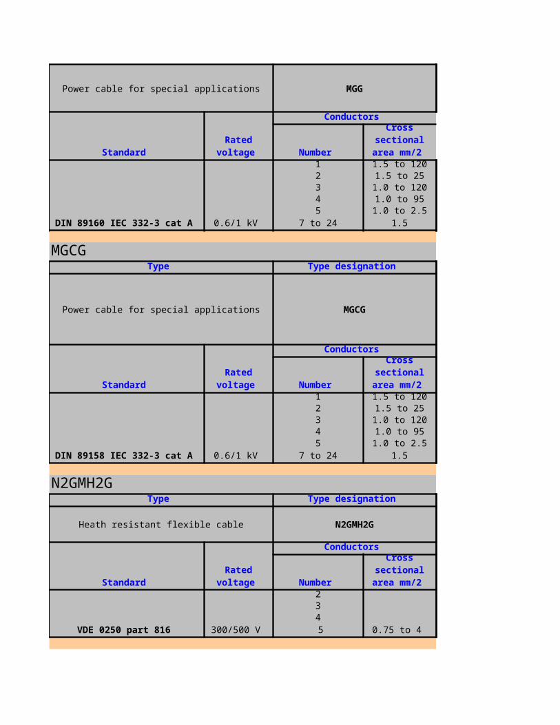
Power cable for special applications MGG
DIN 89160 IEC 332-3 cat A 0.6/1 kV
1 1.5 to 1202 1.5 to 253 1.0 to 1204 1.0 to 955 1.0 to 2.5
7 to 24
MGCG
Power cable for special applications MGCG
DIN 89158 IEC 332-3 cat A 0.6/1 kV
1 1.5 to 1202 1.5 to 253 1.0 to 1204 1.0 to 955 1.0 to 2.5
7 to 24
N2GMH2G
Heath resistant flexible cable N2GMH2G
VDE 0250 part 816 300/500 V
2
0.75 to 4
34
Standard Rated
voltage
Conductors
Number
Cross sectional area
mm/2
1.5
Type Type designation
Standard Rated
voltage
Conductors
Number
Cross sectional area
mm/2
1.5
Type Type designation
Standard Rated
voltage
Conductors
Number
Cross sectional area
mm/2
5

NSGAFou
Power cable for special applications NSGAFou
VDE 0250 part 602 3.6/6 kV 1 1.5 to 185
NTSCGEWou
Trailing cable NTSCGEWou
VDE 0250 part 813 6/10 kV 3 25 to 150
H05RR-F
Ordinary tough rubber - sheathed cord H05RR-F
Type Type designation
Standard Rated
voltage
Conductors
Number
Cross sectional area
mm/2
Type Type designation
Standard Rated
voltage
Conductors
Number
Cross sectional area
mm/2
Type Type designation
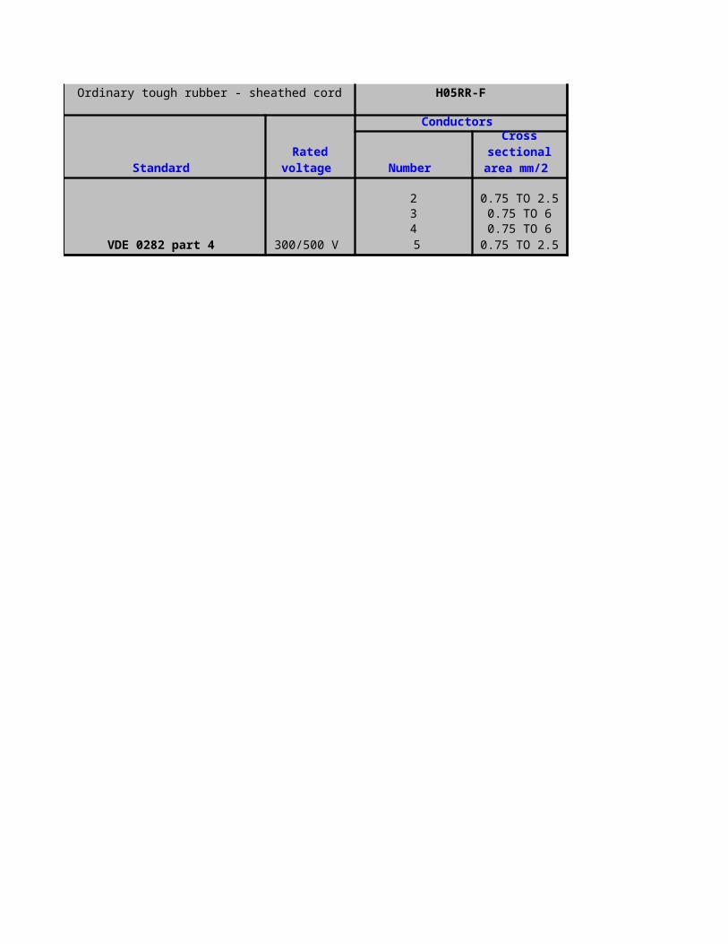
Ordinary tough rubber - sheathed cord H05RR-F
VDE 0282 part 4 300/500 V
2 0.75 TO 2.53 0.75 TO 64 0.75 TO 6
0.75 TO 2.5
Standard Rated
voltage
Conductors
Number
Cross sectional area
mm/2
5
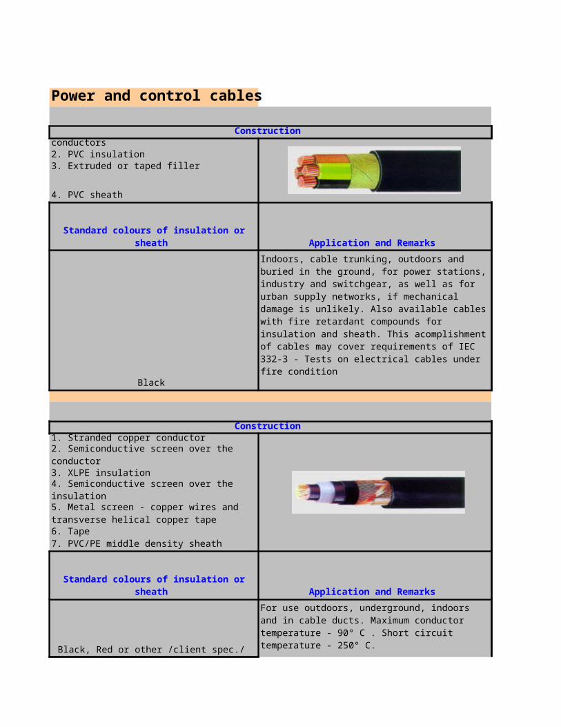
Power and control cables
1. Solid or stranded copper conductors2. PVC insulation3. Extruded or taped filler
4. PVC sheath
Black
1. Stranded copper conductor
2. Semiconductive screen over the conductor3. XLPE insulation
4. Semiconductive screen over the insulation
6. Tape7. PVC/PE middle density sheath
Black, Red or other /client spec./
Construction
Standard colours of insulation or sheath Application and Remarks
Indoors, cable trunking, outdoors and buried in the ground, for power stations, industry and switchgear, as well as for urban supply networks, if mechanical damage is unlikely. Also available cables with fire retardant compounds for insulation and sheath. This acomplishment of cables may cover requirements of IEC 332-3 - Tests on electrical cables under fire condition
Construction
5. Metal screen - copper wires and transverse helical copper tape
Standard colours of insulation or sheath Application and Remarks
For use outdoors, underground, indoors and in cable ducts. Maximum conductor temperature - 90° C . Short circuit temperature - 250° C.

1. Solid or stranded aluminium conductor
2. Semiconductive screen over the conductor3. XLPE insulation
4. Semiconductive screen over the insulation
6. Tape7. PVC/PE middle density sheath
Black, Red or other /client spec./
1. Stranded copper conductors
2. Semiconductive screen over the conductor3. XLPE insulation
4. Semiconductive screen over the insulation5. Semiconductive swelling tape
7. Swelling tape8. PE middle density sheath
Black, Red or other /client spec./
Construction
5. Metal screen - copper wires and transverse helical copper tape
Standard colours of insulation or sheath Application and Remarks
For use outdoors, underground, indoors and in cable ducts. Maximum conductor temperature - 90° C . Short circuit temperature - 250° C.
Construction
6. Metal screen - copper wires and transverse helical copper tape
Standard colours of insulation or sheath Application and Remarks
For use outdoors, underground, indoors and in cable ducts. Maximum conductor temperature - 90° C. Short circuit temperature - 250° C. The use of these cables is necessary where the longitudinal penetration of water caused by mechanical damage shall be prevented.
Construction

1. Solid or stranded aluminium conductors
2. Semiconductive screen over the conductor3. XLPE insulation
4. Semiconductive screen over the insulation5. Semiconductive swelling tape
7. Swelling tape8. PE middle density sheath
Black, Red or other /client spec./
1. Stranded copper conductors
2. Semiconductive screen over the conductor3. XLPE insulation
4. Semiconductive screen over the insulation
6. Fillers7. PVC
Black, Red or other /client spec./
1. Solid or stranded aluminium conductors
2. Semiconductive screen over the conductor3. XLPE insulation
6. Metal screen - copper wires and transverse helical copper tape
Standard colours of insulation or sheath Application and Remarks
For use outdoors, underground, indoors and in cable ducts. Maximum conductor temperature - 90° C. Short circuit temperature - 250° C. The use of these cables is necessary where the longitudinal penetration of water caused by mechanical damage shall be prevented.
Construction
5. Metal screen - copper tape above each individual core
Standard colours of insulation or sheath Application and Remarks
For use outdoors, underground, indoors and in cable ducts. Maximum conductor temperature - 90° C . Short circuit temperature - 250° C.
Construction

4. Semiconductive screen over the insulation
6. Fillers7. PVC sheath
Black, Red or other /client spec./
1. Stranded copper conductors
2. Semiconductive screen over the conductor3. XLPE insulation
4. Semiconductive screen over the insulation
6. Halogen free fire retardant filling7. Halogen free fire retardant sheath
Natural
1. Solid or stranded alluminium conductors
2. Semiconductive screen over the conductor3. XLPE insulation
4. Semiconductive screen over the insulation
6. Halogen free fire retardant filling
5. Metal screen - copper tape above each individual core
Standard colours of insulation or sheath Application and Remarks
For use outdoors, underground, indoors and in cable ducts. Maximum conductor temperature - 90° C . Short circuit temperature - 250° C.
Construction
5. Metal screen - copper tape above each individual core
Standard colours of insulation or sheath Application and Remarks
For use outdoors, under ground, indoors and in cable ducts. Maximum conductor temperature - 90° C. Short circuit temperature - 250° C. These halogen free cables are installed at airports, hospitals, multiple-stores buildings and
Construction
5. Metal screen - copper tape above each individual core
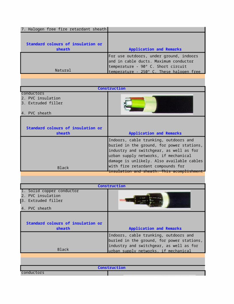
7. Halogen free fire retardant sheath
Natural
1. Solid or stranded alluminium conductors2. PVC insulation3. Extruded filler
4. PVC sheath
Black
1. Solid copper conductor2. PVC insulation3. Extruded filler
4. PVC sheath
Black
1. Solid or stranded copper conductors
Standard colours of insulation or sheath Application and Remarks
For use outdoors, under ground, indoors and in cable ducts. Maximum conductor temperature - 90° C. Short circuit temperature - 250° C. These halogen free cables are installed at airports, hospitals, multiple-stores buildings and
Construction
Standard colours of insulation or sheath Application and Remarks
Indoors, cable trunking, outdoors and buried in the ground, for power stations, industry and switchgear, as well as for urban supply networks, if mechanical damage is unlikely. Also available cables with fire retardant compounds for insulation and sheath. This acomplishment of cables may cover requirements of IEC 332-3 - Tests on electrical cables under fire condition.
Construction
Standard colours of insulation or sheath Application and Remarks
Indoors, cable trunking, outdoors and buried in the ground, for power stations, industry and switchgear, as well as for urban supply networks, if mechanical damage is unlikely. Also available cables with fire retardant compounds for insulation and sheath.
Construction
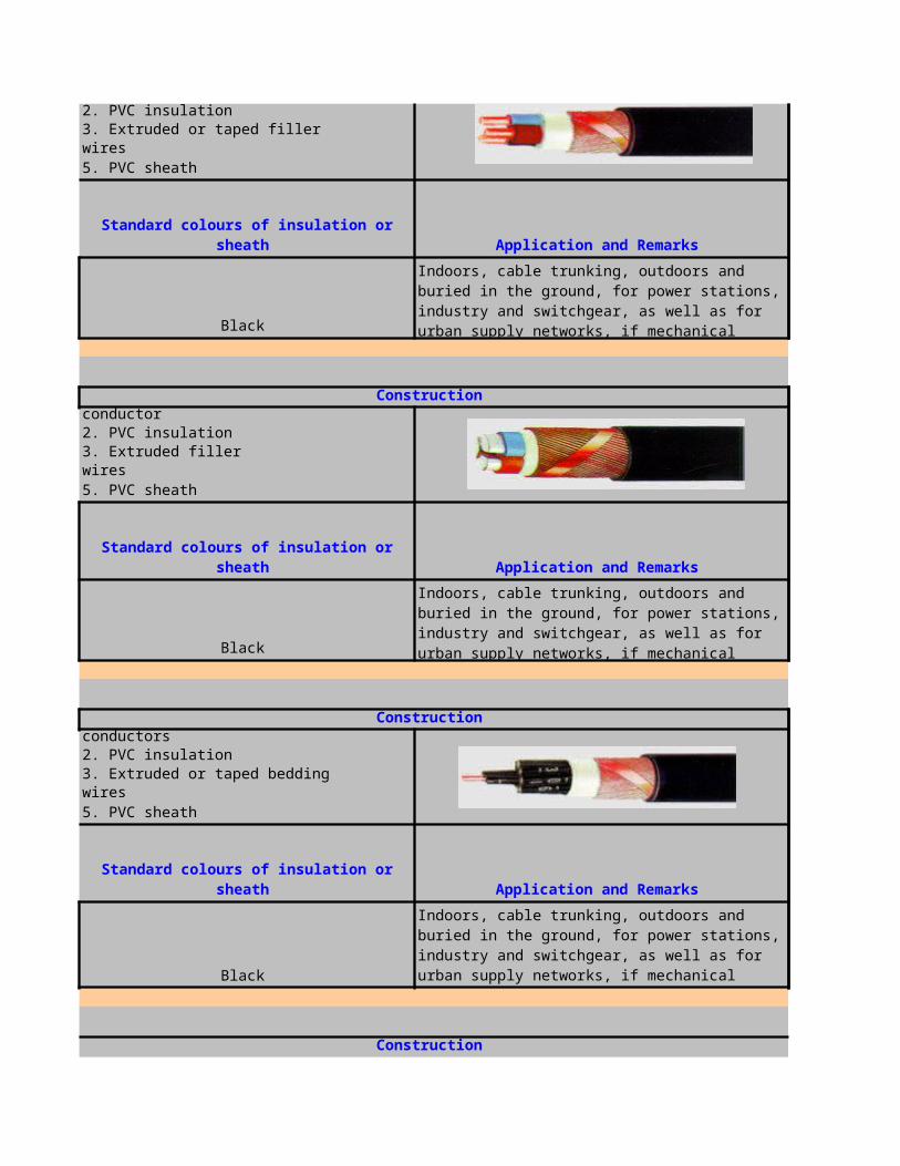
2. PVC insulation3. Extruded or taped filler4. Concentric conductor - copper wires5. PVC sheath
Black
1. Solid or stranded alluminium conductor2. PVC insulation3. Extruded filler4. Concentric conductor - copper wires5. PVC sheath
Black
1. Solid or stranded copper conductors2. PVC insulation3. Extruded or taped bedding4. Concentric conductor - copper wires5. PVC sheath
Black
Standard colours of insulation or sheath Application and Remarks
Indoors, cable trunking, outdoors and buried in the ground, for power stations, industry and switchgear, as well as for urban supply networks, if mechanical damage is unlikely. Also available cables with fire retardant compounds for insulation and sheath.
Construction
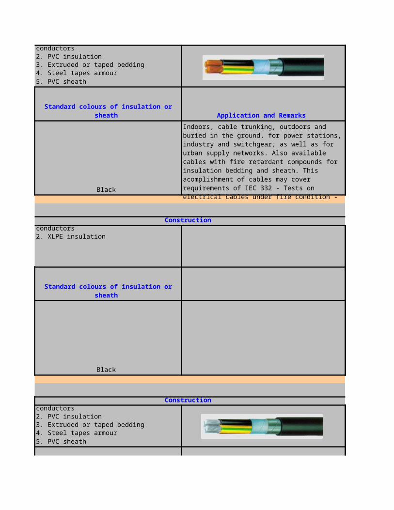
1. Solid or stranded copper conductors2. PVC insulation3. Extruded or taped bedding4. Steel tapes armour5. PVC sheath
Black
1. Solid or stranded copper conductors2. XLPE insulation
Black
1. Solid or stranded alluminium conductors2. PVC insulation3. Extruded or taped bedding4. Steel tapes armour5. PVC sheath
Standard colours of insulation or sheath Application and Remarks
Indoors, cable trunking, outdoors and buried in the ground, for power stations, industry and switchgear, as well as for urban supply networks. Also available cables with fire retardant compounds for insulation bedding and sheath. This acomplishment of cables may cover requirements of IEC 332 - Tests on electrical cables under fire condition -Part 3: Tests on bunched wires or cables.
Construction
Standard colours of insulation or sheath
Construction
Standard colours of insulation or sheath Application and Remarks
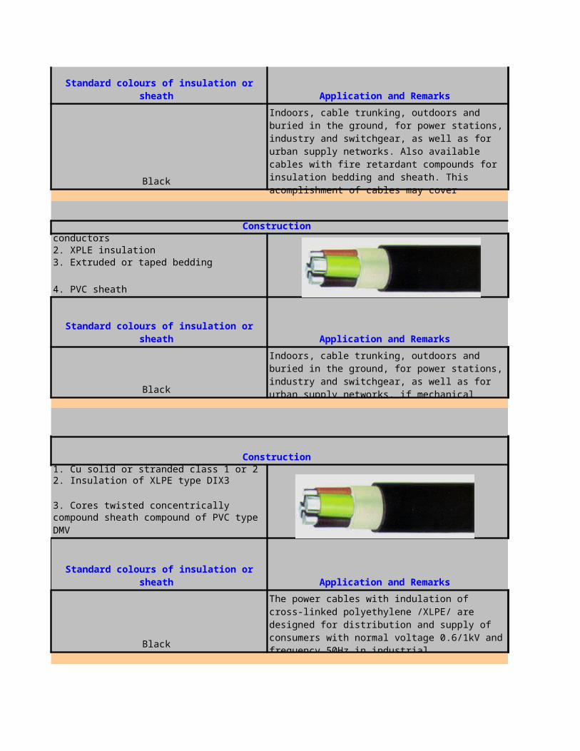
Black
1. Solid or stranded alluminium conductors2. XPLE insulation3. Extruded or taped bedding
4. PVC sheath
Black
1. Cu solid or stranded class 1 or 2
3. Cores twisted concentrically
Black
Standard colours of insulation or sheath Application and Remarks
Indoors, cable trunking, outdoors and buried in the ground, for power stations, industry and switchgear, as well as for urban supply networks. Also available cables with fire retardant compounds for insulation bedding and sheath. This acomplishment of cables may cover requirements of IEC 332 - Tests on electrical cables under fire condition -Part 3: Tests on bunched wires or cables.
Construction
Standard colours of insulation or sheath Application and Remarks
Indoors, cable trunking, outdoors and buried in the ground, for power stations, industry and switchgear, as well as for urban supply networks, if mechanical damage is unlikely. Maximum conductor temperature - 90° C.
Construction
2. Insulation of XLPE type DIX3
4. Elastic or plastic filling compound sheath compound of PVC type DMV
Standard colours of insulation or sheath Application and Remarks
The power cables with indulation of cross-linked polyethylene /XLPE/ are designed for distribution and supply of consumers with normal voltage 0.6/1kV and frequency 50Hz in industrial installations and urban networks. They are suitable for fixed indoor assembly in cable ducth and
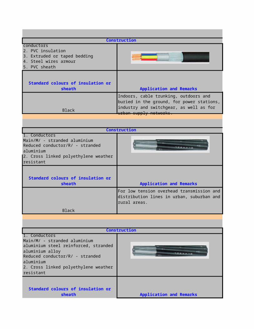
1. Solid or stranded copper conductors2. PVC insulation3. Extruded or taped bedding4. Steel wires armour5. PVC sheath
Black
1. ConductorsMain/M/ - stranded aluminium
Reduced conductor/R/ - stranded aluminium
2. Cross linked polyethylene weather resistant
Black
1. ConductorsMain/M/ - stranded aluminium
Reduced conductor/R/ - stranded aluminium
2. Cross linked polyethylene weather resistant
Construction
Standard colours of insulation or sheath Application and Remarks
Indoors, cable trunking, outdoors and buried in the ground, for power stations, industry and switchgear, as well as for urban supply networks.
Construction
Standard colours of insulation or sheath Application and Remarks
For low tension overhead transmission and distribution lines in urban, suburban and rural areas.
Construction
Supported neutral/N/ stranded aluminium steel reinforced, stranded aluminium alloy
Standard colours of insulation or sheath Application and Remarks
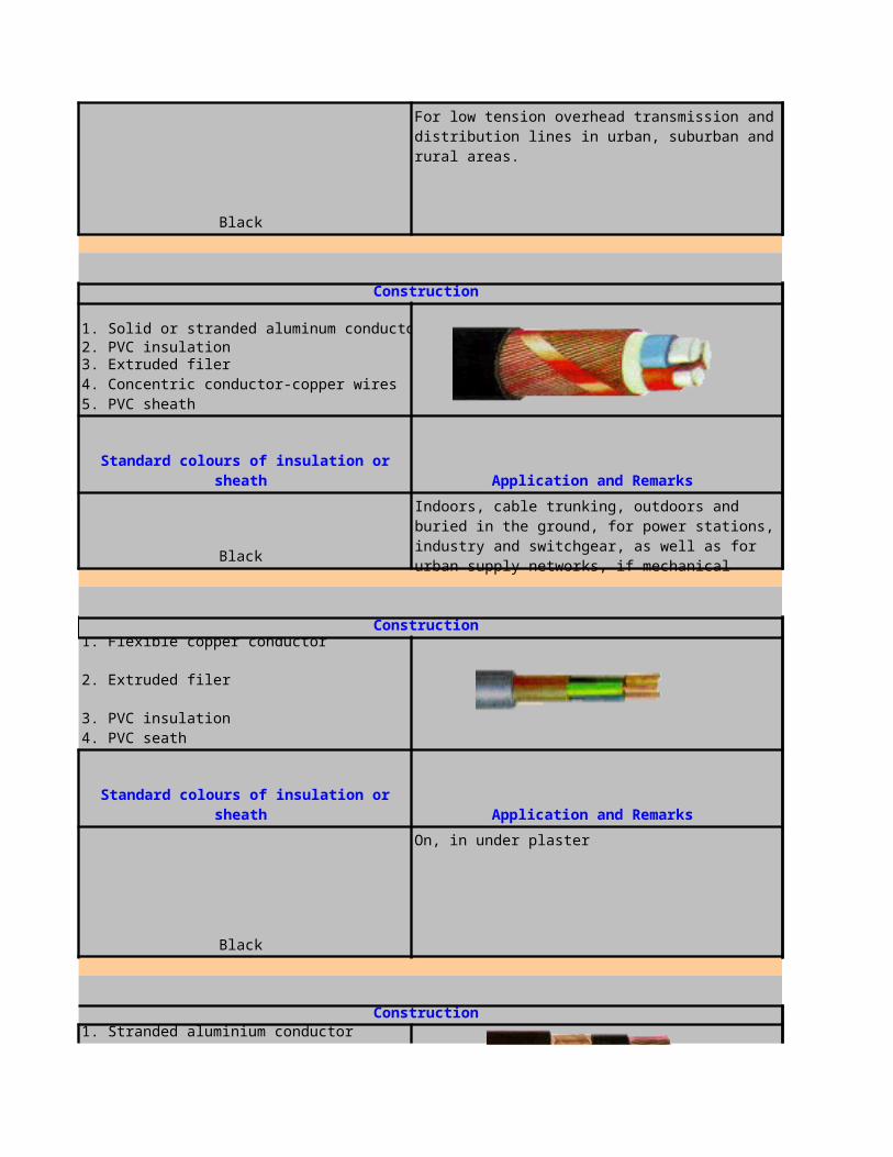
Black
1. Solid or stranded aluminum conductor2. PVC insulation
Black
3. PVC insulation 4. PVC seath
Black
On, in under plaster
1. Stranded aluminium conductor
For low tension overhead transmission and distribution lines in urban, suburban and rural areas.
Construction
3. Extruded filer 4. Concentric conductor-copper wires 5. PVC sheath
Standard colours of insulation or sheath Application and Remarks
Indoors, cable trunking, outdoors and buried in the ground, for power stations, industry and switchgear, as well as for urban supply networks, if mechanical damage is unlikely
Construction 1. Flexible copper conductor
2. Extruded filer
Standard colours of insulation or sheath Application and Remarks
Construction
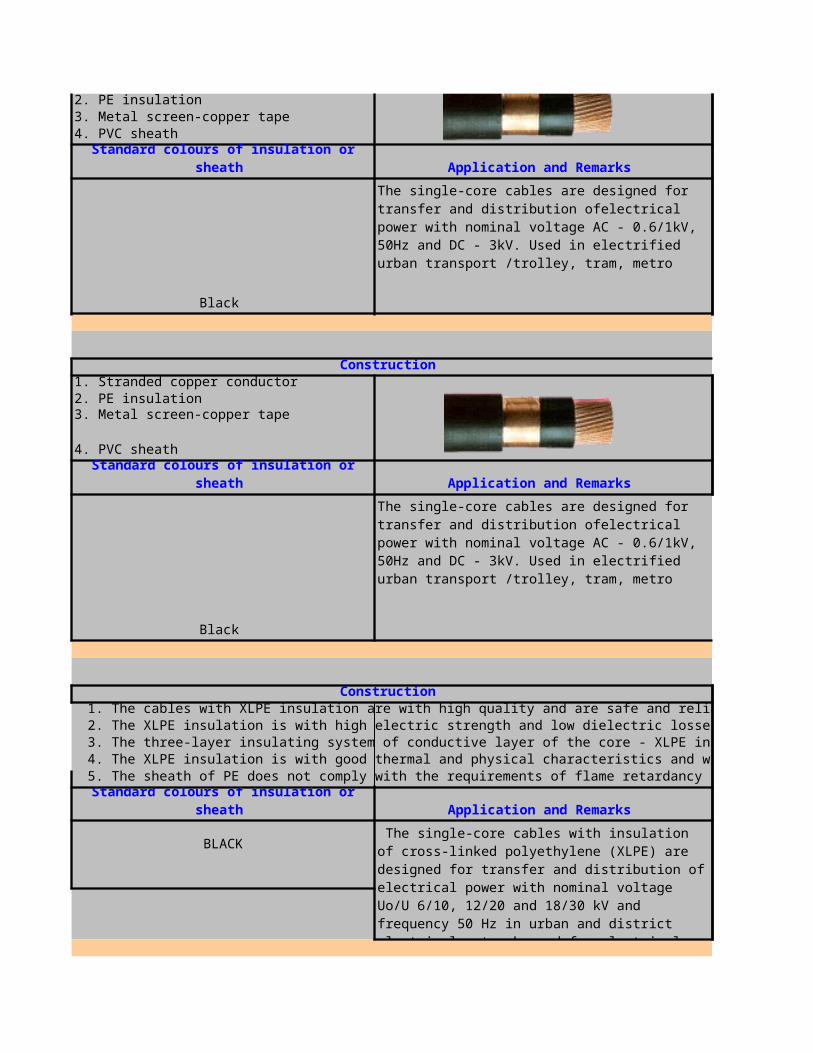
2. PE insulation 3. Metal screen-copper tape 4. PVC sheath
Black
1. Stranded copper conductor 2. PE insulation
4. PVC sheath
Black
1. The cables with XLPE insulation are with high quality and are safe and reliable during exploation.2. The XLPE insulation is with high electric strength and low dielectric losses.3. The three-layer insulating system of conductive layer of the core - XLPE insulation - conductive layer and the technological process of simultaneous triple extrusion provide low level of partial discharges at 2Uo < 2 pC.4. The XLPE insulation is with good thermal and physical characteristics and withstands mechanical loads during laying and installation.5. The sheath of PE does not comply with the requirements of flame retardancy for single cable method B according to VDE 0472 part 804.
BLACK
Standard colours of insulation or sheath Application and Remarks
The single-core cables are designed for transfer and distribution ofelectrical power with nominal voltage AC - 0.6/1kV, 50Hz and DC - 3kV. Used in electrified urban transport /trolley, tram, metro
Construction
3. Metal screen-copper tape
Standard colours of insulation or sheath Application and Remarks
The single-core cables are designed for transfer and distribution ofelectrical power with nominal voltage AC - 0.6/1kV, 50Hz and DC - 3kV. Used in electrified urban transport /trolley, tram, metro
Construction
Standard colours of insulation or sheath Application and Remarks
The single-core cables with insulation of cross-linked polyethylene (XLPE) are designed for transfer and distribution of electrical power with nominal voltage Uo/U 6/10, 12/20 and 18/30 kV and frequency 50 Hz in urban and district electrical networks and for electrical supply of transformers substations, small and medium industrial plants.They are suitable for use in distribution
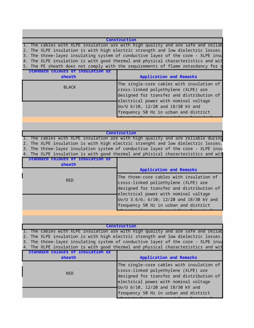
1. The cables with XLPE insulation are with high quality and are safe and reliable during exploation.2. The XLPE insulation is with high electric strength and low dielectric losses.3. The three-layer insulating system of conductive layer of the core - XLPE insulation - conductive layer and the technological process of simultaneous triple extrusion provide low level of partial discharges at 2Uo < 5pC.4. The XLPE insulation is with good thermal and physical characteristics and withstands mechanical loads during laying and installation.5. The PE sheath does not comply with the requirements of flame retardancy for single cable method B according to VDE 0472 part 804.
BLACK
1. The cables with XLPE insulation are with high quality and are reliable during exploitation.2. The XLPE insulation is with high electric strenght and low dielectric losses.3. The three-layer insulation system of conductive layer of the core - XLPE insulation - conductive layer and the technological process of simultaneous triple extrusion provide low level of partial discharges at 2Uo<2pC.4. The XLPE insulation is with good thermal and phisical characteristics and withstands mechanical loads during laying and installation
RED
1. The cables with XLPE insulation are with high quality and are safe and reliable during exploation.2. The XLPE insulation is with high electric strength and low dielectric losses.3. The three-layer insulating system of conductive layer of the core - XLPE insulation - conductive layer and the technological process of simultaneous triple extrusion provide low level of partial discharges at 2Uo < 2 pC.4. The XLPE insulation is with good thermal and physical characteristics and withstands mechanical loads during laying and installation.
RED
Construction
Standard colours of insulation or sheath Application and Remarks
The single-core cables with insulation of cross-linked polyethylene (XLPE) are designed for transfer and distribution of electrical power with nominal voltage Uo/U 6/10, 12/20 and 18/30 kV and frequency 50 Hz in urban and district electrical networks and for electrical supply of transformers substations, small and medium industrial plants. They are suitable for use in distribution installations,
Construction
Standard colours of insulation or sheath Application and Remarks
The three-core cables with insulation of cross-linked poliethylene (XLPE) are designed for transfer and distribution of electrical power with nominal valtage Uo/U 3.6/6; 6/10; 12/20 and 18/30 kV and frequency 50 Hz in urban and district electrical networks and for electrical supply of transformers substations, small and medium industrial plants.They are suitable for use in distribution
Construction
Standard colours of insulation or sheath Application and Remarks
The single-core cables with insulation of cross-linked polyethylene (XLPE) are designed for transfer and distribution of electrical power with nominal voltage Uo/U 6/10, 12/20 and 18/30 kV and frequency 50 Hz in urban and district electrical networks and for electrical supply of transformers substations, small and medium industrial plants.They are suitable for use in distribution
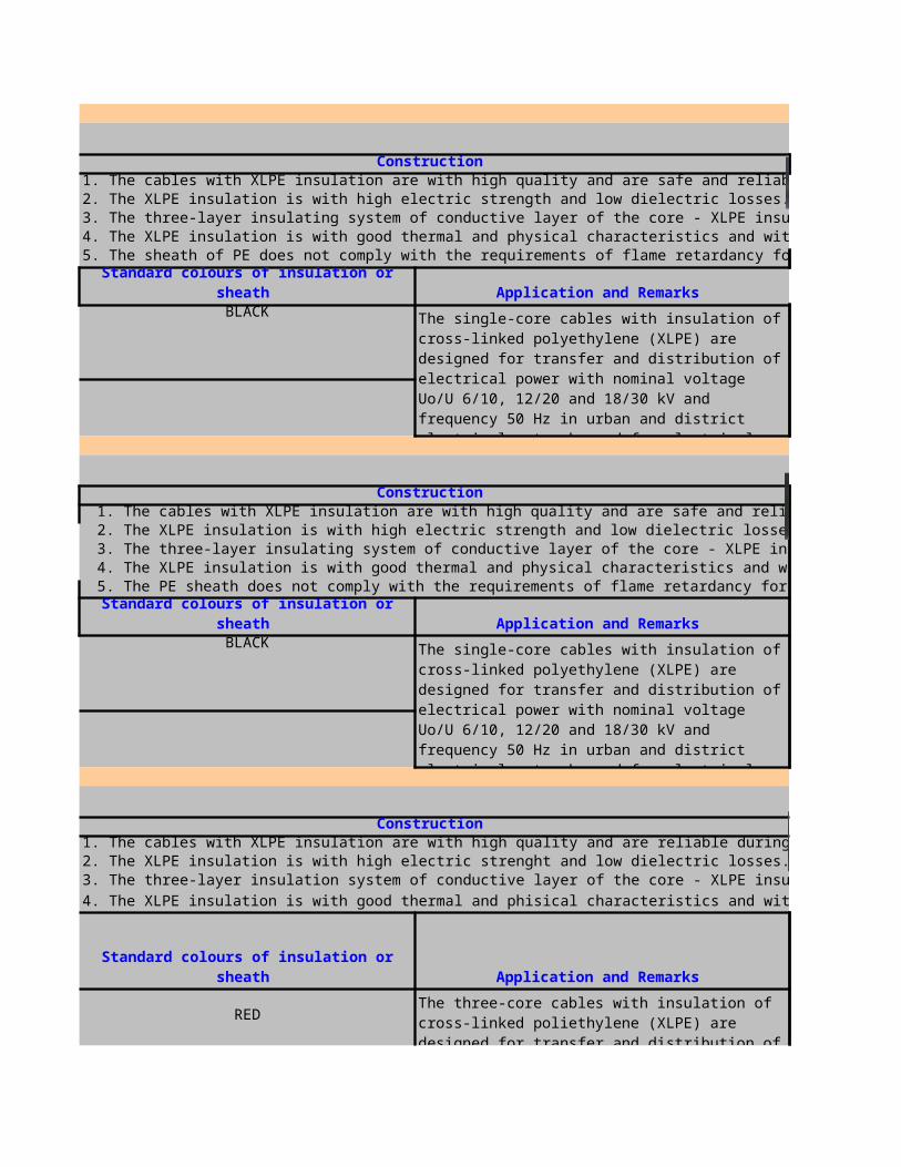
1. The cables with XLPE insulation are with high quality and are safe and reliable during exploation.2. The XLPE insulation is with high electric strength and low dielectric losses.3. The three-layer insulating system of conductive layer of the core - XLPE insulation - conductive layer and the technological process of simultaneous triple extrusion provide low level of partial discharges at 2Uo < 2 pC.4. The XLPE insulation is with good thermal and physical characteristics and withstands mechanical loads during laying and installation.5. The sheath of PE does not comply with the requirements of flame retardancy for single cable method B according to VDE 0472 part 804.
BLACK
1. The cables with XLPE insulation are with high quality and are safe and reliable during exploation.2. The XLPE insulation is with high electric strength and low dielectric losses.3. The three-layer insulating system of conductive layer of the core - XLPE insulation - conductive layer and the technological process of simultaneous triple extrusion provide low level of partial discharges at 2Uo < 5pC.4. The XLPE insulation is with good thermal and physical characteristics and withstands mechanical loads during laying and installation.5. The PE sheath does not comply with the requirements of flame retardancy for single cable method B according to VDE 0472 part 804.
BLACK
1. The cables with XLPE insulation are with high quality and are reliable during exploitation.2. The XLPE insulation is with high electric strenght and low dielectric losses.3. The three-layer insulation system of conductive layer of the core - XLPE insulation - conductive layer and the technological process of simultaneous triple extrusion provide low level of partial discharges at 2Uo<2pC.
4. The XLPE insulation is with good thermal and phisical characteristics and withstands mechanical loads during laying and installation
RED
Construction
Standard colours of insulation or sheath Application and Remarks
The single-core cables with insulation of cross-linked polyethylene (XLPE) are designed for transfer and distribution of electrical power with nominal voltage Uo/U 6/10, 12/20 and 18/30 kV and frequency 50 Hz in urban and district electrical networks and for electrical supply of transformers substations, small and medium industrial plants.They are suitable for use in distribution
Construction
Standard colours of insulation or sheath Application and Remarks
The three-core cables with insulation of cross-linked poliethylene (XLPE) are designed for transfer and distribution of electrical power with nominal valtage Uo/U 3.6/6; 6/10; 12/20 and 18/30 kV and frequency 50 Hz in urban and district electrical networks and for electrical supply of transformers substations, small and medium industrial plants.They are suitable for use in distribution

1. The cables with XLPE insulation are with high quality and are safe and reliable during exploation.2. The XLPE insulation is with high electric strength and low dielectric losses.3. The three-layer insulating system of conductive layer of the core - XLPE insulation - conductive layer and the technological process of simultaneous triple extrusion provide low level of partial discharges at 2Uo < 2 pC.4. The XLPE insulation is with good thermal and physical characteristics and withstands mechanical loads during laying and installation.
RED
1.plain annealed copper conductor,class 2 according to IEC2282.Extruded polyvinyl chloride PVC/A acc. to IEC 5023.Armour of galvanized round steel wires acc. to IEC 5024.outer sheath:Extruded polyvinyl chloride PVC, compound type ST1 acc. to IEC 502,
2cores: black, blue3cores: black, blue, brown
4cores: black, blue, brown, blackabove: black with white numbering
1.plain annealed copper conductor,class 1,2 according to BS63602.Extruded polyvinyl chloride PVC/A acc. to BS 76553. armour of galvanized round steel wires SWA acc. to BS 6346 4. extruded polyvinyl chloride PVC, compound type TM1 acc.to BS 7655
2cores: red, black3cores: red, yellow, blue
4cores: red, yellow, blue, blackabove: white numbered in contrasting colours
The three-core cables with insulation of cross-linked poliethylene (XLPE) are designed for transfer and distribution of electrical power with nominal valtage Uo/U 3.6/6; 6/10; 12/20 and 18/30 kV and frequency 50 Hz in urban and district electrical networks and for electrical supply of transformers substations, small and medium industrial plants.They are suitable for use in distribution
Construction
Standard colours of insulation or sheath Application and Remarks
The single-core cables with insulation of cross-linked polyethylene (XLPE) are designed for transfer and distribution of electrical power with nominal voltage Uo/U 6/10, 12/20 and 18/30 kV and frequency 50 Hz in urban and district electrical networks and for electrical supply of transformers substations, small and medium industrial plants.They are suitable for use in distribution
Construction
Standard colours of insulation or sheath Application and Remarks
For power distribution and controlling in low voltage installation systems. Suitable for indoor and outdoor installation, for direct burial in dry and wet areas.
Construction
Standard colours of insulation or sheath Application and Remarks
For power distribution and controlling in low voltage installation systems. Suitable for indoor and outdoor installation, in dry and wet locations, for direct burial.

1.plain annealed copper conductor,class 1,acc to IEC 2282.cross-linked polyethylene XLPE acc. IEC 502
4. extruded polyvinyl chloride PVC, compound type ST2 acc. to IEC 502, grey
2cores: black,blue3cores: black,blue,brown4cores: black,blue,brown
5cores: black, blue, brown, black, black with wabove: white numbered in contrasting colours
1.plain annealed copper conductor,class 1,acc to IEC 2282.cross-linked polyethylene XLPE acc. IEC 502
4.extruded polyvinyl chloride PVC, compound type ST2 acc. to IEC 502,grey
2cores: black,blue3cores: black,blue,brown4cores: black,blue,brown
5cores: black, blue, brown, black, black with wabove: white numbered in contrasting colours
1.plain annealed copper conductor,class 2,acc to IEC 2282.cross-linked polyethylene XLPE acc. IEC 502
4.extruded polyvinyl chloride PVC, compound type ST2 acc. to IEC 502,grey
2cores: black,blue3cores: black,blue,brown4cores: black,blue,brown
5cores: black, blue, brown, black, black with wabove: white numbered in contrasting colours
For power distribution and controlling in low voltage installation systems. Suitable for indoor and outdoor installation, in dry and wet locations, for direct burial.
Construction
3. braid of galvanized steel wires, wire-Æ: 0.3 mm, over a flat flexible earth
Standard colours of insulation or sheath Application and Remarks
For power distribution and controlling in low voltage installation systems. Suitable for indoor and outdoor installation, in dry and wet locations, for direct burial.
Construction
3.braid of galvanized steel wires, wire-Æ: 0.3 mm
Standard colours of insulation or sheath Application and Remarks
For power distribution and controlling in low voltage installation systems. Suitable for indoor and outdoor installation, in dry and wet locations, for direct burial.
Construction 3.armour of galvanized steel wires (for cross-sections £25 mm² circular,above 25 mm² flat) and plain annealed copper wires; with counter helix of galvanized steel tape
Standard colours of insulation or sheath Application and Remarks
For power distribution and controlling in low voltage installation systems. Suitable for indoor and outdoor installation, in dry and wet locations, for direct burial.
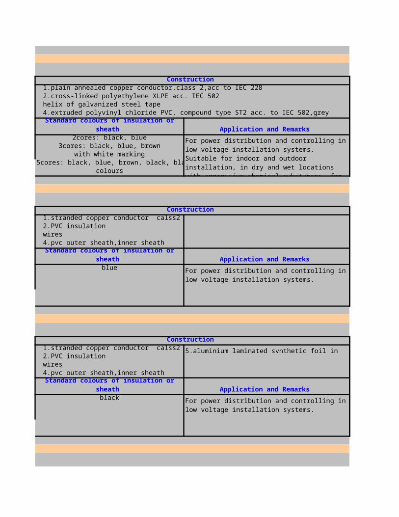
1.plain annealed copper conductor,class 2,acc to IEC 2282.cross-linked polyethylene XLPE acc. IEC 502
4.extruded polyvinyl chloride PVC, compound type ST2 acc. to IEC 502,grey
2cores: black, blue3cores: black, blue, brown
5cores: black, blue, brown, black, black with wabove: black, numbered in contrasting colours
1.stranded copper conductor calss22.PVC insulation3.armour of galvanized round steel wires4.pvc outer sheath,inner sheath
blue
1.stranded copper conductor calss22.PVC insulation3.armour of galvanized round steel wires4.pvc outer sheath,inner sheath
black
Construction
3.armour of galvanized steel wires (for cross-sections £25 mm² circular,above flat) with counter helix of galvanized steel tape
Standard colours of insulation or sheath Application and Remarks
For power distribution and controlling in low voltage installation systems. Suitable for indoor and outdoor installation, in dry and wet locations with aggressive chemical substances, for direct burial.
4cores: black, blue, brown, black with white marking
Construction
Standard colours of insulation or sheath Application and Remarks
For power distribution and controlling in low voltage installation systems.
Construction
5.aluminium laminated synthetic foil in contact with the drain wire
Standard colours of insulation or sheath Application and Remarks
For power distribution and controlling in low voltage installation systems.

1.Tinned stranded copper conductor calss22.EPR insulation3.Halogen free bedding4.pvc outer sheath
Blue For offshore platforms
1.Tinned stranded copper conductor calss22.PE insulation3.pvc outer sheath
4. Aluminium laminated synthetic foil in contact with drain wire
Blue for low voltages lines
1.Tinned stranded copper conductor calss22.PE insulation3.pvc outer sheath
4. Aluminium laminated tape
Blue For petrochemical installations
1.solid copper conductor calss12.PVC insulation3.PVC outer sheath,PVC inner sheath
4.Double steel tape armour
Construction
Standard colours of insulation or sheath Application and Remarks
Construction
Standard colours of insulation or sheath Application and Remarks
Construction
Standard colours of insulation or sheath Application and Remarks
Construction
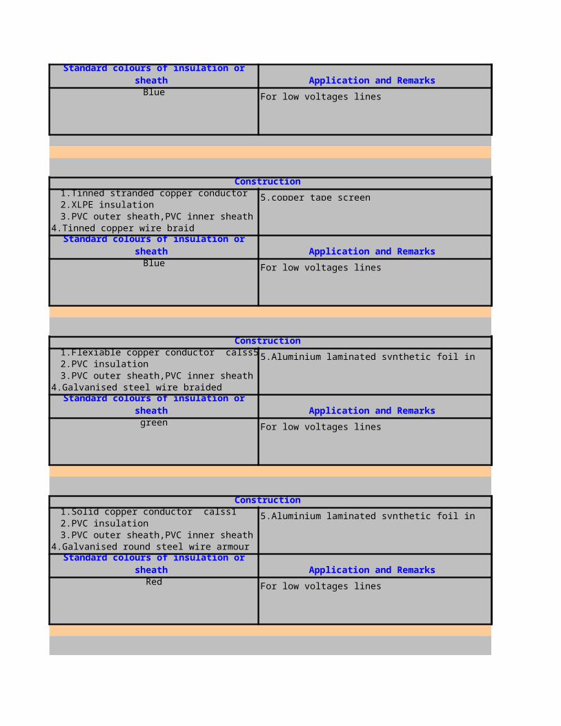
Blue For low voltages lines
1.Tinned stranded copper conductor calss2 5.copper tape screen2.XLPE insulation3.PVC outer sheath,PVC inner sheath
4.Tinned copper wire braid
Blue For low voltages lines
1.Flexiable copper conductor calss52.PVC insulation3.PVC outer sheath,PVC inner sheath
4.Galvanised steel wire braided
green For low voltages lines
1.Solid copper conductor calss12.PVC insulation3.PVC outer sheath,PVC inner sheath
4.Galvanised round steel wire armour
Red For low voltages lines
Standard colours of insulation or sheath Application and Remarks
Construction
Standard colours of insulation or sheath Application and Remarks
Construction
5.Aluminium laminated synthetic foil in contact with the drain wire
Standard colours of insulation or sheath Application and Remarks
Construction
5.Aluminium laminated synthetic foil in contact with the drain wire
Standard colours of insulation or sheath Application and Remarks

1.Solid copper conductor calss12.PE insulation3.PVC outer sheath,PVC inner sheath
4.Galvanised Flat steel wire braided
Grey For low voltages lines
1.Flexiable copper conductor calss52.PE insulation3.PVC outer sheath,PVC inner sheath
4.Galvanised Flat steel wire braided
Blue For low voltages lines
1.Solid copper conductor calss1 5.halogen-free acc. to IEC 754-2 2.PE insulation3.Halogen free fire retardant outer sheath
4. Aluminium laminated synthetic foil in contact with drain wire
Red For low voltages lines
1.Tinned stranded copper conductor calss2 5.halogen-free acc. to IEC 754-2 2.PE insulation3.Halogen free fire retardant outer sheath
4. Aluminium laminated synthetic foil in contact with drain wire
Green For low voltages lines
Construction
Standard colours of insulation or sheath Application and Remarks
Construction
Standard colours of insulation or sheath Application and Remarks
Construction
Standard colours of insulation or sheath Application and Remarks
Construction
Standard colours of insulation or sheath Application and Remarks
For low voltages lines
1.Tinned stranded copper conductor calss22.EPR insulation3.Halogen free fire retardant inner sheath,Halogen free ethylene vinyl acetate
4. Tinned copper wire braided
Grey Halogen free cables for offshore platforms
1.Tinned stranded copper conductor calss22.XLPE insulation3.PVC outer sheath,PVC bedding
4. Tinned copper wire braided
Grey for Ship wiring cables
1.Tinned solid copper conductor calss12.PVC insulation3.PVC outer sheath
4. Aluminium laminated synthetic foil in contact with drain wire
Green For low voltages lines
1.solid copper conductor calss12.Cross linked polyethylene(XLPE) insulation3.PE outer sheath
4. Aluminium tape laminated
Construction
Standard colours of insulation or sheath Application and Remarks
Construction
Standard colours of insulation or sheath Application and Remarks
Construction
Standard colours of insulation or sheath Application and Remarks
Construction
Standard colours of insulation or sheath Application and Remarks

Black For low voltages lines
1.solid copper conductor calss1 5. Lead alloy E sheath2.PE insulation3.PVC outer sheath,PVC inner sheath
4.Galvanised round steel wire armour
Black For low voltages lines
1.Tinned stranded copper conductor calss2 5.Galvanised steel wire braided2.PE insulation3.Copper wire braided4.pvc outer sheath
Blue
INSULATION CROSS SECTIONS
XLPE 1UPTO 20
XLPE 1UPTO 20
XLPE 1UPTO 20
XLPE 1UPTO 20
XLPE 1UPTO 20
XLPE 1UPTO 20
XLPE 1UPTO 20
XLPE 1UPTO 20
INSULATION CROSS SECTIONS
Standard colours of insulation or sheath Application and Remarks
Construction
Standard colours of insulation or sheath Application and Remarks
Construction
Standard colours of insulation or sheath Application and Remarks
For power distribution and controlling in low voltage installation systems.

XLPE 1UPTO 20XLPE 1UPTO 20XLPE 1UPTO 20XLPE 1UPTO 20XLPE 1UPTO 20XLPE 1UPTO 20XLPE 1UPTO 20XLPE 1UPTO 20


1. Solid copper conductor2. PVC insulation
1. Flexible copper conductor2. PVC insulation
1. Flexible copper conductor,plain or tinned2. Silicone-rubber insulation
Construction
Standard colours of insulation or sheath Application and Remarks
Green-yellow, Black, Light blue, Brown, Grey, White, Red, or other
For internal wiring of equipment and protected installation in and on luminaries. Also for installation conduit on and under plaster, but only for signaling system. In damp, wet, location, outdoor, in area with fire and explosion hazard-not permitted.
Construction
Standard colours of insulation or sheath Application and Remarks
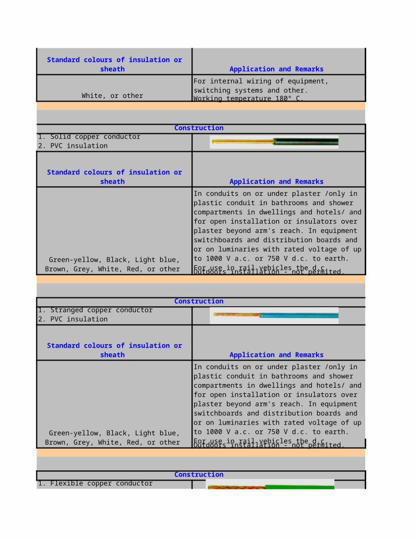
White, or other Working temperature 180° C.
1. Solid copper conductor2. PVC insulation
Outdoors installation - not permited.
1. Stranged copper conductor2. PVC insulation
Outdoors installation - not permited.
1. Flexible copper conductor
Standard colours of insulation or sheath Application and Remarks
For internal wiring of equipment, switching systems and other.
Construction
Standard colours of insulation or sheath Application and Remarks
Green-yellow, Black, Light blue, Brown, Grey, White, Red, or other
In conduits on or under plaster /only in plastic conduit in bathrooms and shower compartments in dwellings and hotels/ and for open installation or insulators over plaster beyond arm's reach. In equipment switchboards and distribution boards and or on luminaries with rated voltage of up to 1000 V a.c. or 750 V d.c. to earth. For use in rail vehicles the d.c. operation voltage may be up to 900 V to earth.
Construction
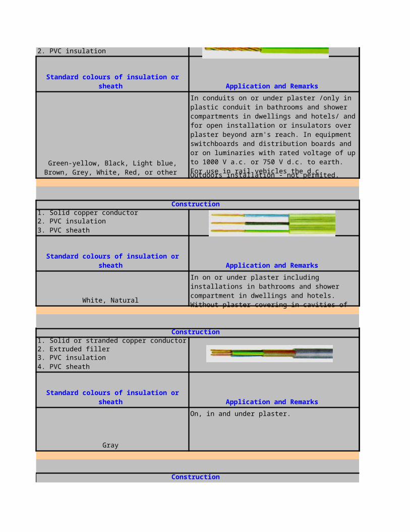
2. PVC insulation
Outdoors installation - not permited.
1. Solid copper conductor2. PVC insulation3. PVC sheath
White, Natural
1. Solid or stranded copper conductor2. Extruded filler3. PVC insulation4. PVC sheath
Gray
On, in and under plaster.
Standard colours of insulation or sheath Application and Remarks
Green-yellow, Black, Light blue, Brown, Grey, White, Red, or other
In conduits on or under plaster /only in plastic conduit in bathrooms and shower compartments in dwellings and hotels/ and for open installation or insulators over plaster beyond arm's reach. In equipment switchboards and distribution boards and or on luminaries with rated voltage of up to 1000 V a.c. or 750 V d.c. to earth. For use in rail vehicles the d.c. operation voltage may be up to 900 V to earth.
Construction
Standard colours of insulation or sheath Application and Remarks
In on or under plaster including installations in bathrooms and shower compartment in dwellings and hotels. Without plaster covering in cavities of ceilings and walls of non flammable materials. Not permited in wooden houses or buildings used for
Construction
Standard colours of insulation or sheath Application and Remarks
Construction
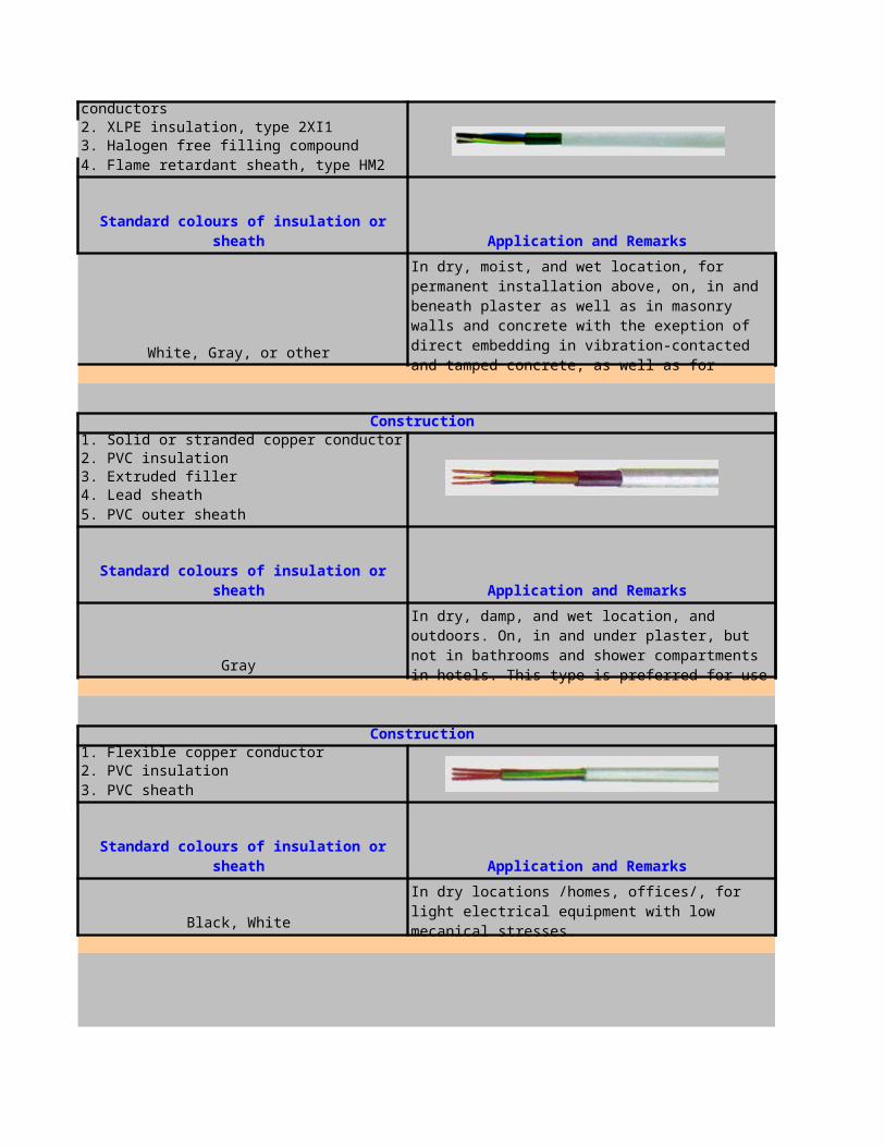
1. Solid or stranded copper conductors2. XLPE insulation, type 2XI13. Halogen free filling compound4. Flame retardant sheath, type HM2
White, Gray, or other
1. Solid or stranded copper conductor2. PVC insulation3. Extruded filler4. Lead sheath5. PVC outer sheath
Gray
1. Flexible copper conductor2. PVC insulation3. PVC sheath
Black, White
H03VV-FStandard: VDE 0281 Part 5, HD21.5S3IEC 227-5
Standard colours of insulation or sheath Application and Remarks
In dry, moist, and wet location, for permanent installation above, on, in and beneath plaster as well as in masonry walls and concrete with the exeption of direct embedding in vibration-contacted and tamped concrete, as well as for outdoor aplication. These cables halogen free cables are installed at airports, hospitals, multiple-stores
Construction
Standard colours of insulation or sheath Application and Remarks
In dry, damp, and wet location, and outdoors. On, in and under plaster, but not in bathrooms and shower compartments in hotels. This type is preferred for use where high safety is demanded - chemical work, heavy industry mining installation
Construction
Standard colours of insulation or sheath Application and Remarks
In dry locations /homes, offices/, for light electrical equipment with low mecanical stresses.
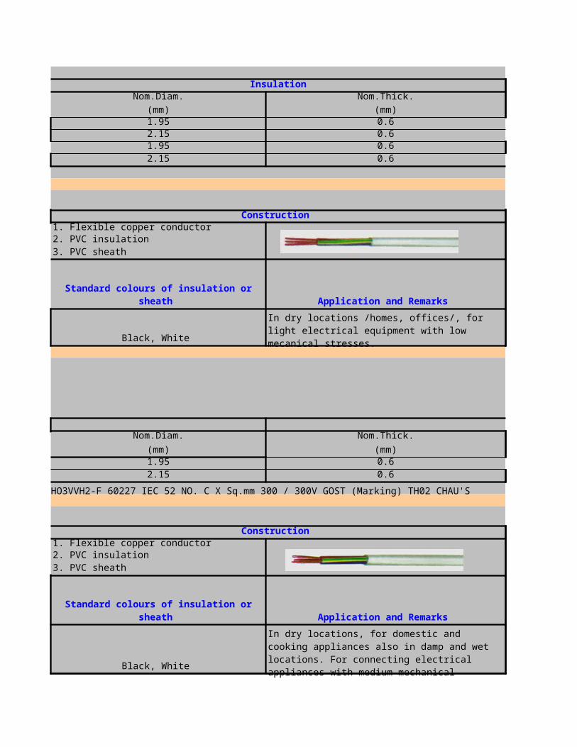
Rating: 70 , 300 / 300V℃Insulation
Nom.Diam. Nom.Thick.
(mm) (mm)1.95 0.62.15 0.61.95 0.62.15 0.6
Marking: H03VV-F (VDE) No. C X Sq.mm KEMA-KEUR CHAU'S BSI
1. Flexible copper conductor2. PVC insulation3. PVC sheath
Black, White
H03VVH2-FStandard: VDE 0281 Part 5, HD21.5S3IEC 227-5Rating: 70 , 300 / 300V℃
Nom.Diam. Nom.Thick.
(mm) (mm)1.95 0.62.15 0.6
Marking: H03VVH2-F (VDE) No. C X Sq.mm KEMA-KEUR CHAU'S GOST (RUSSIA) HO3VVH2-F 60227 IEC 52 NO. C X Sq.mm 300 / 300V GOST (Marking) TH02 CHAU'S
1. Flexible copper conductor2. PVC insulation3. PVC sheath
Black, White
Construction
Standard colours of insulation or sheath Application and Remarks
In dry locations /homes, offices/, for light electrical equipment with low mecanical stresses.
Construction
Standard colours of insulation or sheath Application and Remarks
In dry locations, for domestic and cooking appliances also in damp and wet locations. For connecting electrical appliances with medium mechanical stresses.

H05VV-FStandard: VDE 0281 Part 5, HD21.5S3IEC 227-5Rating: 70 , 300 / 500V℃
Insulation JacketNom.Diam. Nom.Thick.
(mm) (mm)2.35 0.82.55 0.82.9 0.83 0.8
3.65 12.35 0.82.55 0.83.05 0.8
3 0.93.65 1.1
Marking: H05VV-F(VDE) NO. C X Sq.mm KEMA-KEUR CHAU'S BSI
1. Flexible copper conductor2. PVC insulation3. PVC sheath
Black, White
H05VVH2-FStandard: VDE 0281 Part 5, HD21, 5S3IEC 227-5Rating: 70 , 300 / 500V℃
Insulation JacketNom.Diam. Nom.Thick.
(mm) (mm)2.35 0.82.5 0.8
Marking: HO5VVH2-F( VDM) No. C Size Sq.mm KEMA-KEUR CHAU'S GOST (RUSSIA) H05VVH2-F 60227 IEC 53 No. C X Sq.mm 300 / 500V GOST( Marking) TH02 CHAU'S
H03VH-Y
Construction
Standard colours of insulation or sheath Application and Remarks
In dry locations, for domestic and cooking appliances also in damp and wet locations. For connecting electrical appliances with medium mechanical stresses.

Standard: VDE 0281 Part 5, HD21.5S3IEC 227-5Rating: 70 , 300 / 300V℃
InsulationNom.Diam.
(mm)2.80 x 5.50
Marking: H03VH -Y(VDE) No. C Size Sq.mm KEMA-KEUR CHAU'S
Standard: HD21.12 S1Rating: 90 , 300 / 500V℃
Insulation JacketNom.Diam. Nom.Thick.
(mm) (mm)2.35 0.82.55 0.82.35 0.82.55 0.8
Marking: H05 V(sub)2(/sub)V(sub)2(/sub)-F (VED) No. C X Sq.mm KEMA-KEUR CHAU\'S
Standard: HD21.12 S1Rating: 90 , 300 / 500V℃
Insulation JacketNom.Diam. Nom.Thick.
(mm) (mm)2.2 0.7
2.35 0.62.55 0.6
PNCTFKStranded Copper ConductorStranded: JISC 3301: 2000Rating: 300V
Insulation JacketNom.Diam. Nom.Thick.
(mm) (mm)2.4 0.9
2.75 0.93.15 0.9
Marking: 11-5099 D.Q. CHAU'S E. PNCTFK sq.mm

1. Flexible copper conductor tinned2. EPR insulation3. Polychloroprene sheath
Black
1. Flexible copper conductor tinned2. EPR insulation
4. Polychloroprene outer sheath
Black
1. Flexible copper conductor /class 6/2. Separator3. Polychloroprene sheath
Black
Construction
Standard colours of insulation or sheath Application and Remarks
In dry and wet locations and outdoors. For connecting electrical appliances and tools with low mechanical stresses.
Construction
3. Synthetic elastomer inner sheath /in some cases/
Standard colours of insulation or sheath Application and Remarks
In dry and wet locations and outdoors. In agricultural operating areas and those subject to fire hazard. For connecting electrical appliances and tools, including industrial equipment with medium mechanical stresses.
Construction
Standard colours of insulation or sheath Application and Remarks
In dry, damp and wet locations and outdoors. For very high mechanical stresses as machine and hand welding cables.
Construction
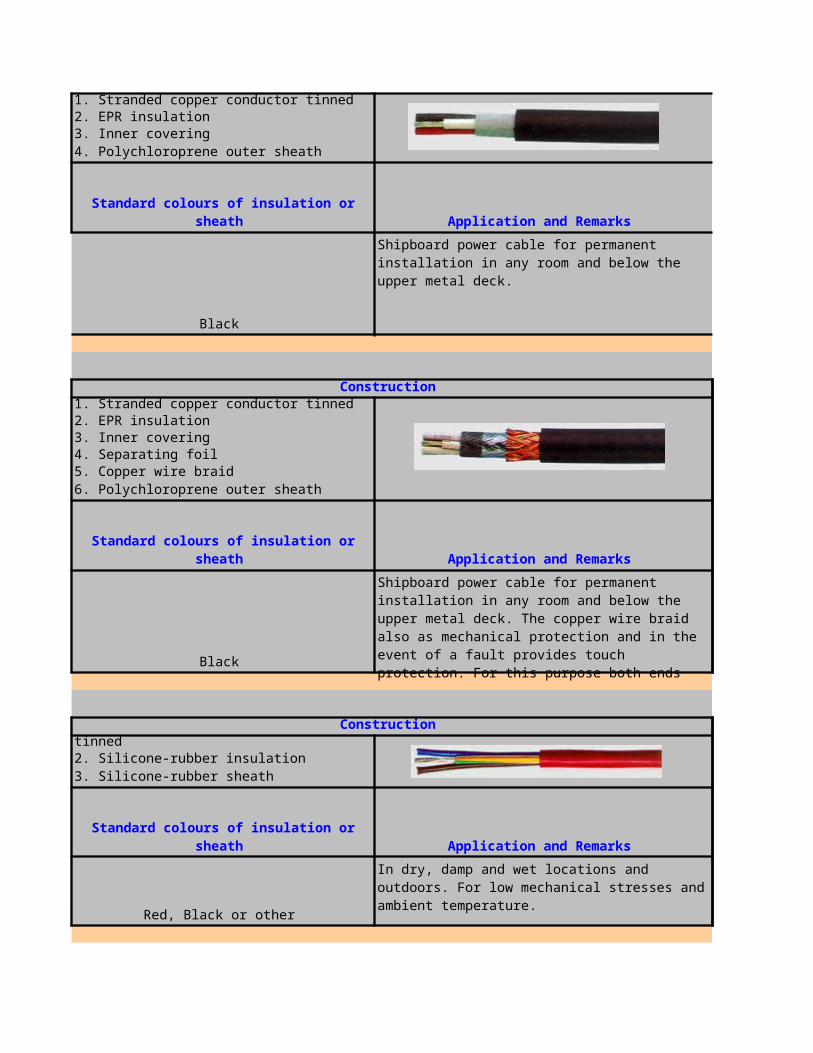
1. Stranded copper conductor tinned2. EPR insulation3. Inner covering4. Polychloroprene outer sheath
Black
1. Stranded copper conductor tinned2. EPR insulation3. Inner covering4. Separating foil5. Copper wire braid6. Polychloroprene outer sheath
Black
1. Flexible copper conductor plain or tinned2. Silicone-rubber insulation3. Silicone-rubber sheath
Red, Black or other
Standard colours of insulation or sheath Application and Remarks
Shipboard power cable for permanent installation in any room and below the upper metal deck.
Construction
Standard colours of insulation or sheath Application and Remarks
Shipboard power cable for permanent installation in any room and below the upper metal deck. The copper wire braid also as mechanical protection and in the event of a fault provides touch protection. For this purpose both ends must be securely earthed by screws.
Construction
Standard colours of insulation or sheath Application and Remarks
In dry, damp and wet locations and outdoors. For low mechanical stresses and ambient temperature.
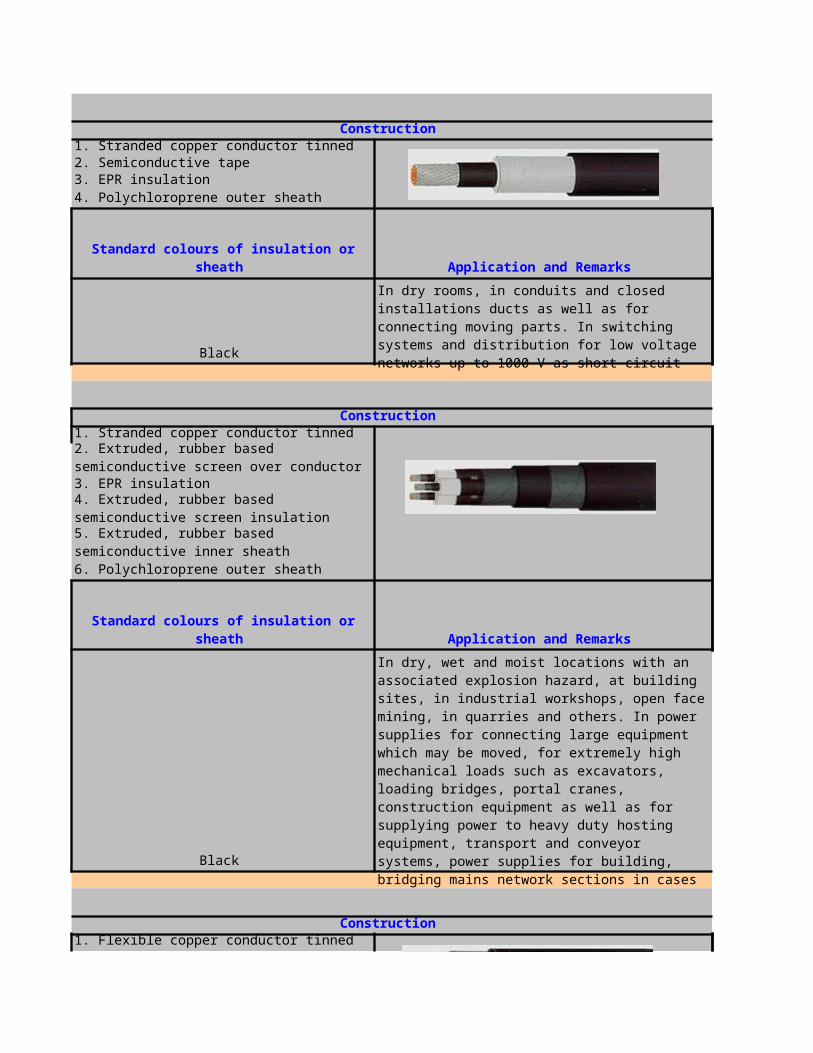
1. Stranded copper conductor tinned2. Semiconductive tape3. EPR insulation4. Polychloroprene outer sheath
Black
1. Stranded copper conductor tinned
3. EPR insulation
6. Polychloroprene outer sheath
Black
1. Flexible copper conductor tinned
Construction
Standard colours of insulation or sheath Application and Remarks
In dry rooms, in conduits and closed installations ducts as well as for connecting moving parts. In switching systems and distribution for low voltage networks up to 1000 V as short circuit and inherently earth-fault-proof.
Construction
2. Extruded, rubber based semiconductive screen over conductor
4. Extruded, rubber based semiconductive screen insulation
5. Extruded, rubber based semiconductive inner sheath
Standard colours of insulation or sheath Application and Remarks
In dry, wet and moist locations with an associated explosion hazard, at building sites, in industrial workshops, open face mining, in quarries and others. In power supplies for connecting large equipment which may be moved, for extremely high mechanical loads such as excavators, loading bridges, portal cranes, construction equipment as well as for supplying power to heavy duty hosting equipment, transport and conveyor systems, power supplies for building, bridging mains network sections in cases of power failure and for similar applications.
Construction

2. EPR insulation3. EPR sheath
Black
Standard colours of insulation or sheath Application and Remarks
In dry, location /homes, kitchens, office.For connecting electrical appliances with low mechanical stresses


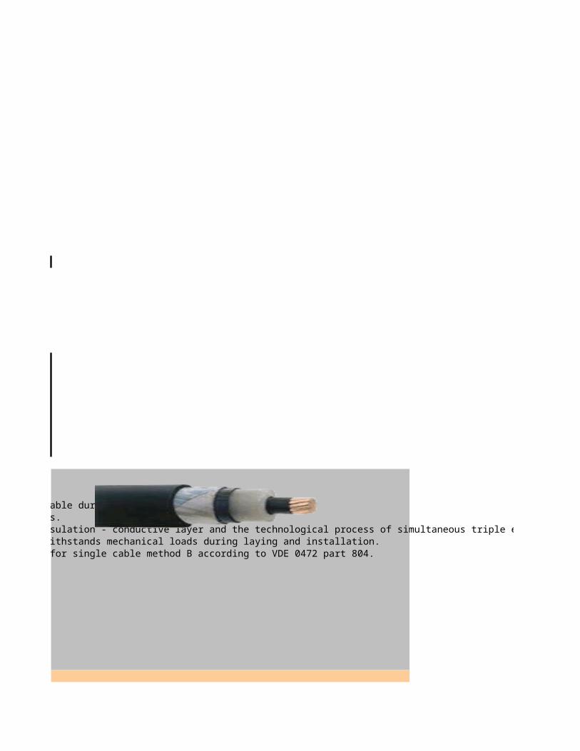
1. The cables with XLPE insulation are with high quality and are safe and reliable during exploation.
3. The three-layer insulating system of conductive layer of the core - XLPE insulation - conductive layer and the technological process of simultaneous triple extrusion provide low level of partial discharges at 2Uo < 2 pC.4. The XLPE insulation is with good thermal and physical characteristics and withstands mechanical loads during laying and installation.5. The sheath of PE does not comply with the requirements of flame retardancy for single cable method B according to VDE 0472 part 804.

1. The cables with XLPE insulation are with high quality and are safe and reliable during exploation.
3. The three-layer insulating system of conductive layer of the core - XLPE insulation - conductive layer and the technological process of simultaneous triple extrusion provide low level of partial discharges at 2Uo < 5pC.4. The XLPE insulation is with good thermal and physical characteristics and withstands mechanical loads during laying and installation.5. The PE sheath does not comply with the requirements of flame retardancy for single cable method B according to VDE 0472 part 804.
3. The three-layer insulation system of conductive layer of the core - XLPE insulation - conductive layer and the technological process of simultaneous triple extrusion provide low level of partial discharges at 2Uo<2pC.4. The XLPE insulation is with good thermal and phisical characteristics and withstands mechanical loads during laying and installation
1. The cables with XLPE insulation are with high quality and are safe and reliable during exploation.
3. The three-layer insulating system of conductive layer of the core - XLPE insulation - conductive layer and the technological process of simultaneous triple extrusion provide low level of partial discharges at 2Uo < 2 pC.4. The XLPE insulation is with good thermal and physical characteristics and withstands mechanical loads during laying and installation.

1. The cables with XLPE insulation are with high quality and are safe and reliable during exploation.
3. The three-layer insulating system of conductive layer of the core - XLPE insulation - conductive layer and the technological process of simultaneous triple extrusion provide low level of partial discharges at 2Uo < 2 pC.4. The XLPE insulation is with good thermal and physical characteristics and withstands mechanical loads during laying and installation.5. The sheath of PE does not comply with the requirements of flame retardancy for single cable method B according to VDE 0472 part 804.
1. The cables with XLPE insulation are with high quality and are safe and reliable during exploation.
3. The three-layer insulating system of conductive layer of the core - XLPE insulation - conductive layer and the technological process of simultaneous triple extrusion provide low level of partial discharges at 2Uo < 5pC.4. The XLPE insulation is with good thermal and physical characteristics and withstands mechanical loads during laying and installation.5. The PE sheath does not comply with the requirements of flame retardancy for single cable method B according to VDE 0472 part 804.
3. The three-layer insulation system of conductive layer of the core - XLPE insulation - conductive layer and the technological process of simultaneous triple extrusion provide low level of partial discharges at 2Uo<2pC.
4. The XLPE insulation is with good thermal and phisical characteristics and withstands mechanical loads during laying and installation
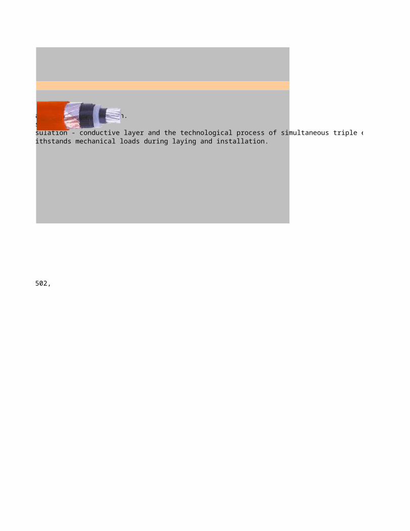
1. The cables with XLPE insulation are with high quality and are safe and reliable during exploation.
3. The three-layer insulating system of conductive layer of the core - XLPE insulation - conductive layer and the technological process of simultaneous triple extrusion provide low level of partial discharges at 2Uo < 2 pC.4. The XLPE insulation is with good thermal and physical characteristics and withstands mechanical loads during laying and installation.

APPLICATIONS
1
1
1
1
1
1
1
1
APPLICATIONS
NUMBEROF CORES
POWER CABLE FOR POWER NETWORKS,GROUND,AIRDUCTS
NUMBEROF CORES

11111111
POWER CABLE FOR POWER NETWORKS,GROUND,AIRDUCTS
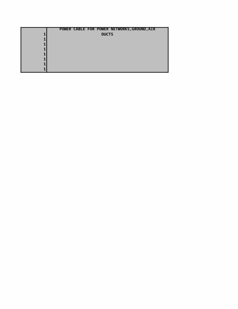


H03VV-F

JacketNom.Diam.
(mm)5.35.65.46
Marking: H03VV-F (VDE) No. C X Sq.mm KEMA-KEUR CHAU'S BSI
H03VVH2-F
JacketNom.Diam.
(mm)3.5 X 5.73.6 X 5.8
Marking: H03VVH2-F (VDE) No. C X Sq.mm KEMA-KEUR CHAU'S GOST (RUSSIA) HO3VVH2-F 60227 IEC 52 NO. C X Sq.mm 300 / 300V GOST (Marking) TH02 CHAU'S
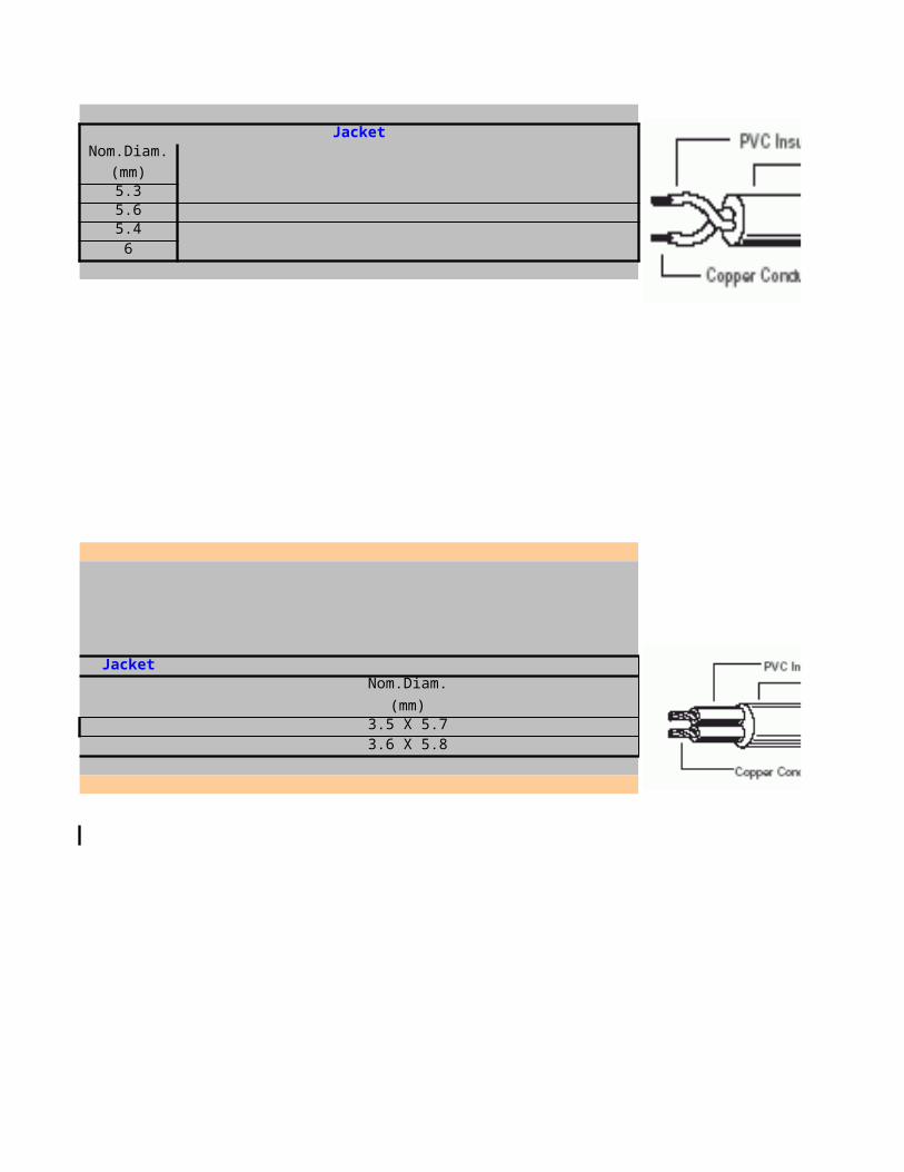
H05VV-F
JacketNom.Diam.
(mm)6.36.87.47.89.37
7.28.158.3
10.1
Marking: H05VV-F(VDE) NO. C X Sq.mm KEMA-KEUR CHAU'S BSI
H05VVH2-F
Nom.Diam.
(mm)4.10 x 6.504.35 x 7.00
Marking: HO5VVH2-F( VDM) No. C Size Sq.mm KEMA-KEUR CHAU'S GOST (RUSSIA) H05VVH2-F 60227 IEC 53 No. C X Sq.mm 300 / 500V GOST( Marking) TH02 CHAU'S
H03VH-Y

Marking: H03VH -Y(VDE) No. C Size Sq.mm KEMA-KEUR CHAU'S
JacketNom.Diam.
(mm)6.46.87
7.2
Marking: H05 V(sub)2(/sub)V(sub)2(/sub)-F (VED) No. C X Sq.mm KEMA-KEUR CHAU\'S
JacketNom.Diam.
(mm)3.75 x 6.004.20 x 6.604.40 x 6.90
PNCTFK
JacketNom.Diam.
(mm)4.50 x 6.604.90 x 7.405.30 x 8.00
Marking: 11-5099 D.Q. CHAU'S E. PNCTFK sq.mm


3. The three-layer insulating system of conductive layer of the core - XLPE insulation - conductive layer and the technological process of simultaneous triple extrusion provide low level of partial discharges at 2Uo < 2 pC.
3. The three-layer insulating system of conductive layer of the core - XLPE insulation - conductive layer and the technological process of simultaneous triple extrusion provide low level of partial discharges at 2Uo < 5pC.
3. The three-layer insulation system of conductive layer of the core - XLPE insulation - conductive layer and the technological process of simultaneous triple extrusion provide low level of partial discharges at 2Uo<2pC.
3. The three-layer insulating system of conductive layer of the core - XLPE insulation - conductive layer and the technological process of simultaneous triple extrusion provide low level of partial discharges at 2Uo < 2 pC.
3. The three-layer insulating system of conductive layer of the core - XLPE insulation - conductive layer and the technological process of simultaneous triple extrusion provide low level of partial discharges at 2Uo < 2 pC.
3. The three-layer insulating system of conductive layer of the core - XLPE insulation - conductive layer and the technological process of simultaneous triple extrusion provide low level of partial discharges at 2Uo < 5pC.
3. The three-layer insulation system of conductive layer of the core - XLPE insulation - conductive layer and the technological process of simultaneous triple extrusion provide low level of partial discharges at 2Uo<2pC.

3. The three-layer insulating system of conductive layer of the core - XLPE insulation - conductive layer and the technological process of simultaneous triple extrusion provide low level of partial discharges at 2Uo < 2 pC.
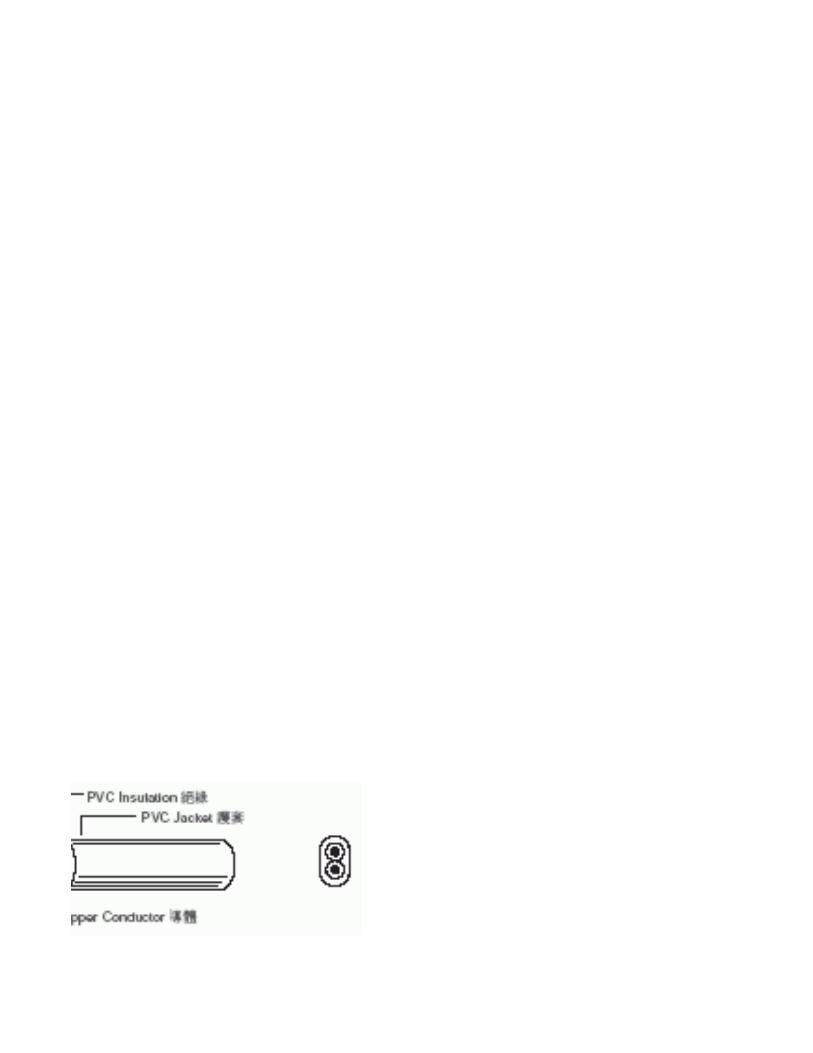
TELECOMMUNICATION - CABLESA-PMzbc similar
A-PMzbc similar
1. Solid copper conductor2. Paper insulation3. Cores twisted in star quad4. Paper tapes5. Lead sheath with antimony content6. Bedding from bitum and impregnated cable paper7. Armour made of two steel tapes8. Steath made of sinthetic threads, bitum and chalk
VDE 0816 3 x 4 to 0.9
-
A-PMz similar
A-PMz similar
1. Solid copper conductor2. Paper insulation3. Cores twisted in star quad4. Paper tapes5. Lead sheath with antimony content
VDE 0816 3 x 4 to 0.9
-
A-2Y/L/2Y similar
A-2Y/L/2Y similar
1. Solid copper conductor2. PE insulation3. Cores twisted in star quad4. Plastic tapes
6. PE outher sheath
VDE 0816
6 x 2 to 0.32
Black
1200x 2 0.40.50.6
HOME PAGENEXT PAGE
PREVIOUS PAGE
Type Type designation Construction
Low frequency cable, paper insulated, lead sheathed and steel
tapes armour
Standard
Conductors
Standard colours of insulation or sheath Number Diameter
114 x 4 1.2
Type Type designation Construction
Low frequency cable, paper insulated, lead
sheathed
Standard
Conductors
Standard colours of insulation or sheath Number Diameter
114 x 4 1.2
Type Type designation Construction
Telecommunication cable, for local
networks 5. Plastic coated aluminium foil with copper drain wire - static screen over the cable core
Standard
Conductors
Standard colours of insulation or sheath Number Diameter
0.7
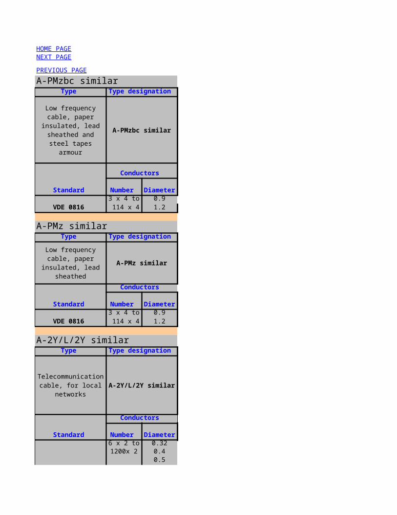
A-2YF/L/2Y similar
A-2YF/L/2Y similar
1. Solid copper conductor2. PE insulation3. Cores twisted in star quad4. Petrojelly filling5. Paper tape6. Plastic coated aluminium foil applied longitudinally7. PE outher sheath
VDE 0816
6 x 2 to 0.4
Black
200 x 2 0.56 x 2 0.6
A-02YSF/L/2Y similar
1. Solid copper conductor2. Foam skin PE insulation3. Cores twisted in star quad4. Petrojelly filling5. Paper tape6. Plastic coated aluminium foil applied longitudinally7. PE outher sheath
VDE 0816
6 x 2 to 0.4
Black
200 x 2 0.56 x 2 0.6
J-Y/St/ Y…Lg
J-Y/St/ Y…Lg
1. Solid copper conductor2. PVC insulation3. Cores twisted in pairs4. Plastic tape
6. PVC outher sheath
VDE 0815 1 x 2 to 0.6
Gray
FTP 4x2x0,5
Type Type designation Construction
Telecommunication cable, for local
networks
Standard
Conductors
Standard colours of insulation or sheath Number Diameter
100 x 2 0.7
Type Type designation Construction
Telecommunication cable, for local
networks
A-02YSF/L/2Y similar
Standard
Conductors
Standard colours of insulation or sheath Number Diameter
100 x 2 0.7
Type Type designation Construction
Installation telephone cables
5. Plastic coated aluminium foil with copper drain wire - static screen over the cable core
Standard
Conductors
Standard colours of insulation or sheath Number Diameter
100 x 2 0.8
Type Type designation Construction

FTP 4x2x0,5
1. conductor: solid copper, diameter 0,5 mm2. diameter over insulation 0,96 mm3. total number of pairs 44. stranded cable core longitudinally taped with 2 tapes, providing a 30% overlap:5. mylar tape 25mm width, 23µm thickness6. Al/PE tape with adge folding with aluminium inside, 25mm width, 50÷70µm thickness7. drain wire of soft tinned Cu wire, diameter 0,5 mm, longi
8. gray PVC sheath
IEC-11801/19954x2 0.5 9. max cable diameter 5,6 mm
10. sheath printed: BFK SA Cable FTP 4x2x0,5 Cat.5, "B",
STP 4x2x0,5
STP 4x2x0,5
1. conductor: solid copper, diameter 0,5 mm2. diameter over insulation 0,96 mm3. total number of pairs 44. stranded cable core longitudinally taped with 2 tapes, providing a 30% overlap:5. mylar tape 25mm width, 23µm thickness6. Al/PE tape with adge folding with aluminium inside, 25mm width, 50÷70µm thickness7. additionally cable core braided with CuSn wires
8. drain wire of soft tinned Cu wire, diameter 0,5 mm, longi
IEC-11801/19954x2 0.5 9. gray PVC sheath
10. max cable diameter 7,0 mm11. sheath printed: BFK SA Cable STP 4x2x0,5 Cat.5, "B", rm
UTP 4x2x0,5
-
UTP 4x2x0,5
1. conductor: solid copper, diameter 0,5 mm2. diameter over insulation 0,96 mm3. total number of pairs 44. gray PVC sheath5. max cable diameter 5,3 mm6. sheath printed: BFK SA Cable UTP 4x2x0,5 Cat.5, "B", rm
IEC-11801/19954x2 0.5 --
PK
PK
1. The coaxial cables consist of an inner copper conductorwhich is plain or stranded2. PE insulation3. Screen of copper braid or Al-tape with copper braid4.PVC outer sheath
Data transmission cables
Standard
Conductors
Number Diameter
Type Type designation Construction
Data transmission cables
Standard
Conductors
Number Diameter
Type Type designation Construction
Standard
Conductors
Standard colours of insulation or sheath Number Diameter
Type Type designation Construction
RF, TV and SAT coaxial cables - 50om
and 75om
Standard
Conductors
Standard colours of insulation or sheath
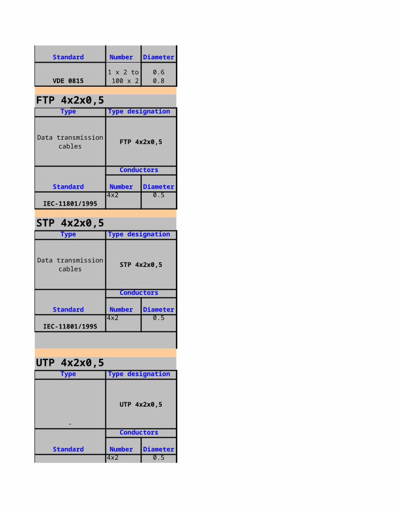
EMKA-TC 14.002-941 1 - 1.67 --
RG 58C/U, RG 213U
Coaxial cables RG 58C/U, RG 213U
1. Nominal impedance - 50om2. Nominal capacitance - 101 pF/m3. Max. attenuation at 200 MHz - 10.2 dB/100m
MIL-C-17--
1 3.14
TWAVB Lg
TWAVB Lg
1.copper conductor2.PE insulation3.armouring:steel wire/steel tape
4. pvc outer sheath,colour grey
NBN 751/68--
Standard Standard colours of insulation or sheath Number Diameter
Type Type designation Construction
Standard colours of insulation or sheath
Standard
Conductors
Number Diameter
Type Type designation Construction
Standard colours of insulation or sheath
Standard
Conductors
Number Diameter
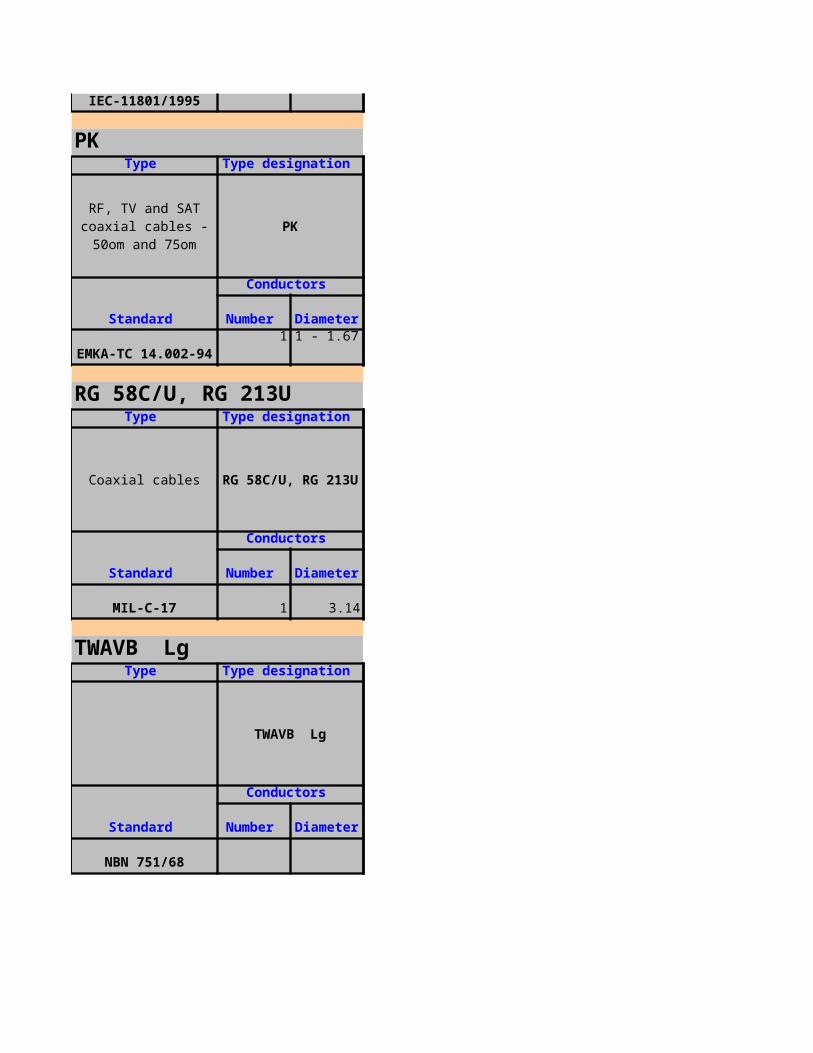
In collectors, channels or tubes.
Outdoor distribution ducted or direct buired telephone cable.
Construction
Application and Remarks
In excavations for all types of soils, with small tension exertions and inclination of the area less than 45 degree.
Construction
Application and Remarks
Construction
Application and Remarks

Construction
Application and Remarks
Outdoor telephone cable for underground installation in cable ducts and conduits, as well as interior installation the use of these cables for power applications is not permitted.
Construction
Application and Remarks
Outdoor telephone cable for underground installation in cable ducts and conduits, as well as interior installation the use of these cables for power applications is not permitted.
Construction
Application and Remarks
Indoor telephone cables transmit analogue or digital signals and are intended for static installation. In communications engineering the following connections can for example made: telephone, fax, telex, or standart modems, intruder alarm systems, entry control,
Construction
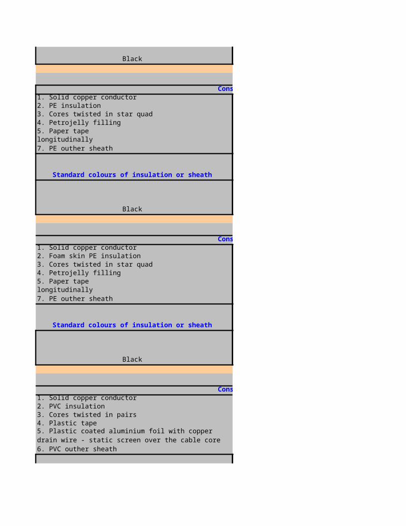
4. stranded cable core longitudinally taped with 2 tapes, providing a 30% overlap:
6. Al/PE tape with adge folding with aluminium inside, 25mm width, 50÷70µm thickness
4. stranded cable core longitudinally taped with 2 tapes, providing a 30% overlap:
6. Al/PE tape with adge folding with aluminium inside, 25mm width, 50÷70µm thickness
11. sheath printed: BFK SA Cable STP 4x2x0,5 Cat.5, "B", rm
6. sheath printed: BFK SA Cable UTP 4x2x0,5 Cat.5, "B", rm
1. The coaxial cables consist of an inner copper conductorwhich is plain or stranded
Application and Remarks
- patch cord- horizontal cables
Construction
Application and Remarks
- patch cord- horizontal cables
Construction
Application and Remarks
- patch cord- horizontal cables
Construction
Application and Remarks

Application and Remarks
They can be used for high frequency or control and measuring equipment and for TV antennas and SAT
Construction
Application and Remarks
Coaxial cables are used in high frequency transmission, especially for transmitters amd receivers, computers, radio amd TV transmissions. The varied mechanical, thermal and electronic properties of coaxial cables meam that they can be used up into the
Construction
Application and Remarks
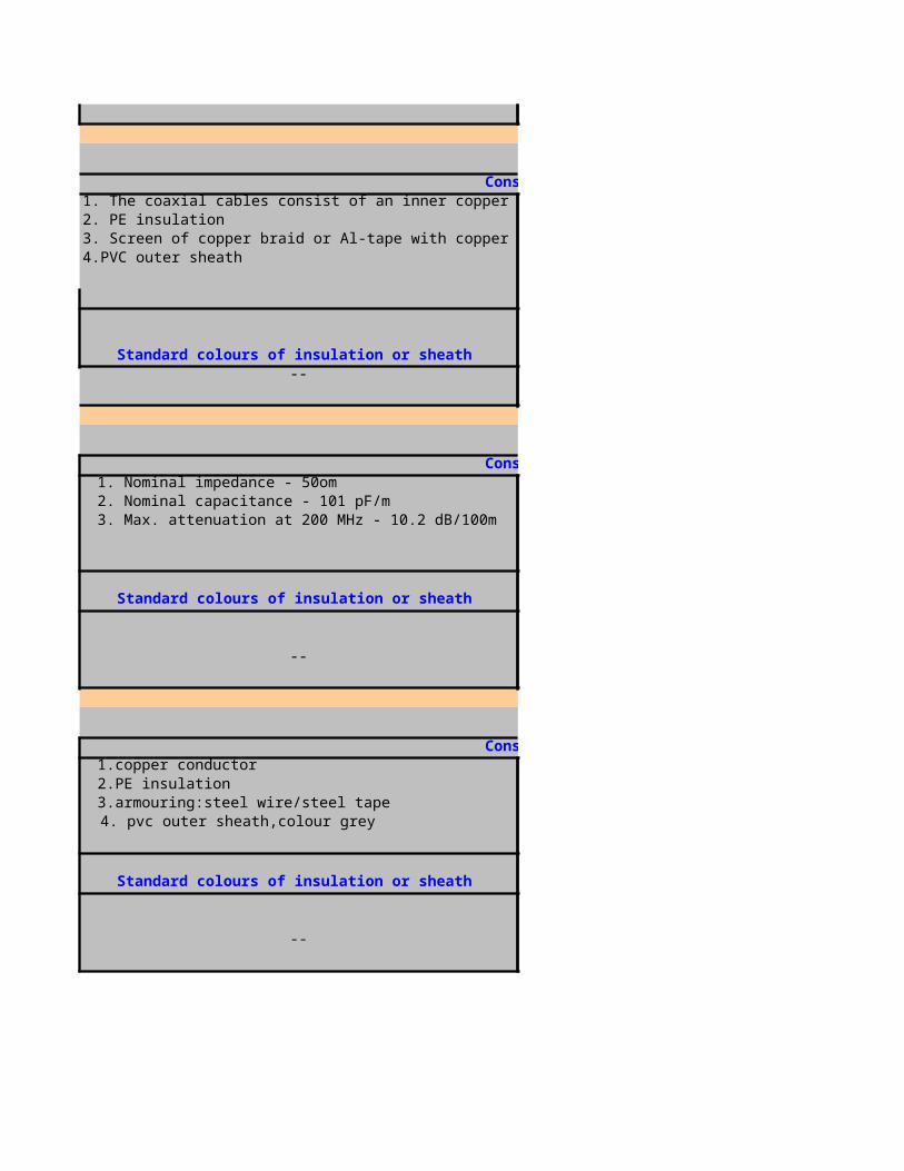
PEI/OSCR/PVC/FRRT,RE-2Y(St)Yfl
RE-2Y(St)Yfl
For 4 - 20 mA analogous signals and digital signals in and around process control; indoor and outdoor use in dry and wet locations, not recommended for direct burial
Geometrical DATA ,RATED VOLTAGE:300/500V
Number OF PAIRS Conductor size(mm)Cross section 0.5 mm2
10 1/0.8 0.520 1/0.8 0.530 1/0.8 0.550 1/0.8 0.5
Cross section 1 mm21 1/1.13 0.62 1/1.13 0.6
PEI/PSCR/OSCR/PVC/FRRT,RE-2Y(St)Yf
RE-2Y(St)Yfl PiMF
HOME PAGENEXT PAGE
PREVIOUS PAGE
Type Type designation
Instrumentation cable,PE-insulated, overall screened,PVC served
Application and Remarks
Thicknessof
insulation(mm)
Type Type designation
Instrumentation cable,PE-insulated, overall screened,PVC served

RE-2Y(St)Yfl PiMF
For 4 - 20 mA analogous signals and digital signals in and around process control with improved reduction of internal interferences; indoor and outdoor use in dry and wet locations, not recommended for direct burialGeometrical DATA ,RATED VOLTAGE:300/500V
Number OF PAIRS Conductor size(mm)Cross section 0.5 mm2
10 1/0.8 0.520 1/0.8 0.530 1/0.8 0.550 1/0.8 0.5
Cross section 1 mm22 1/1.13 0.6
PEI/OSCR/PE/SWB/PVC/FRRT,RE-2Y(St
RE-2Y(St)2YQYfl
For 4 - 20 mA analogous signal and digital signals in and around process control; indoor and outdoor use in dry and wet locations, for direct burial without agressive chemical substancesGeometrical DATA ,RATED VOLTAGE:300/500V
Number OF PAIRS Conductor size(mm)Cross section 0.5 mm2
10 1/0.8 0.520 1/0.8 0.530 1/0.8 0.550 1/0.8 0.5
Cross section 1 mm21 1/1.13 0.62 1/1.13 0.6
Instrumentation cable,PE-insulated, overall screened,PVC served
Application and Remarks
Thicknessof
insulation(mm)
Type Type designation
Instrumentation cable,PE-insulated, overall screened,PVC served,ARMOURED
Application and Remarks
Thicknessof
insulation(mm)

PEI/OSCR/PE/SWA/PVC/FRRT,RE-2Y(S
RE-2Y(St)2YSWAYfl
For 4 - 20 mA analogous signals and digital signals in and around process control; indoor and outdoor use in dry and wet locations, for direct burial without agressive chemical substancesGeometrical DATA ,RATED VOLTAGE:300/500V
Number OF PAIRS Conductor size(mm)Cross section 0.5 mm2
10 1/0.8 0.520 1/0.8 0.530 1/0.8 0.550 1/0.8 0.5
Cross section 1 mm21 1/1.13 0.62 1/1.13 0.6
PEI/PSCR/OSCR/PE/SWA/PVC/FRRT,RE
RE-2Y(St)2YSWAfl PiMF
For 4 - 20 mA analogous signals and digital signals in and around process control with improved reduction of internal interferences, indoor and outdoor use in dry and wet locations, for direct burial without agressive chemical substances
Type Type designation
Instrumentation cable,PE-insulated, overall screened,PVC served,ARMOURED
Application and Remarks
Thicknessof
insulation(mm)
Type Type designation
Instrumentation cable,PE-insulated, overall screened,PVC served,ARMOURED
Application and Remarks
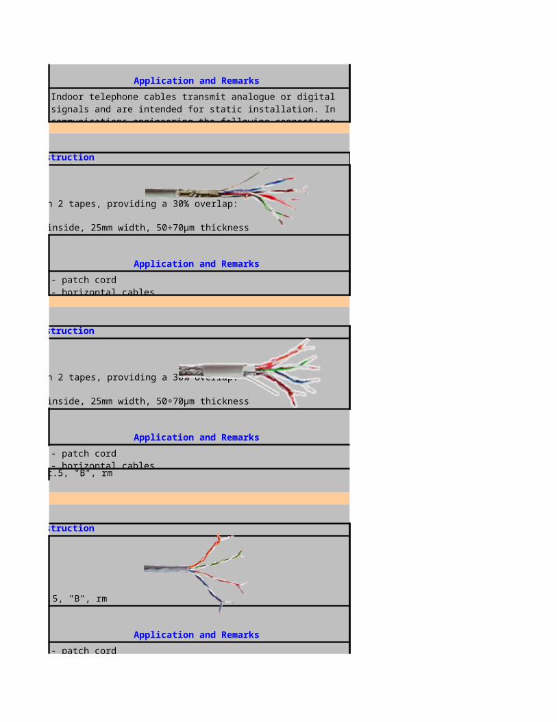
Geometrical DATA ,RATED VOLTAGE:300/500V
Number OF PAIRS Conductor size(mm)Cross section 0.5 mm2
10 1/0.8 0.520 1/0.8 0.530 1/0.8 0.550 1/0.8 0.5
Cross section 1 mm22 1/1.13 0.6
PEI/PSCR/OSCR/PE/SWB/PVC/FRRT,RE-
RE-2Y(St)2YQYfl PiMF
For 4 - 20 mA analogous signals and digital signals in and around process control with improved reduction of internal interferences, indoor and outdoor use in dry and wet locations, for direct burial without agressive chemical substancesGeometrical DATA ,RATED VOLTAGE:300/500V
Number OF PAIRS Conductor size(mm)Cross section 0.5 mm2
10 1/0.8 0.520 1/0.8 0.530 1/0.8 0.550 1/0.8 0.5
Cross section 1 mm22 1/1.13 0.6
PEI/OSCR/PVC/LC/PVC/SWA/PVC/FRRT
Thicknessof
insulation(mm)
Type Type designation
Instrumentation cable,PE-insulated, overall screened,PVC served,ARMOURED
Application and Remarks
Thicknessof
insulation(mm)
Type Type designation
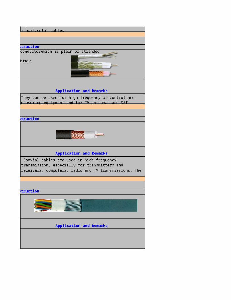
RE-2Y(St)YMZYSWAYfl
For 4 - 20 mA analogous signals and digital signals in and around process control with improved reduction of internal interferences, indoor and outdoor use in dry and wet locations, for direct burial with agressive chemical substancesGeometrical DATA ,RATED VOLTAGE:300/500V
Number OF PAIRS Conductor size(mm)Cross section 0.5 mm2
10 1/0.8 0.520 1/0.8 0.530 1/0.8 0.550 1/0.8 0.5
Cross section 1 mm21 1/1.13 0.62 1/1.13 0.6
PEI/PSCR/OSCR/PVC/LC/PVC/SWA/PVC
RE-2Y(St)YMZYSWAYfl PiMF
Instrumentation cable,PE-insulated, overall screened,PVC served,ARMOURED,lead sheath
Application and Remarks
Thicknessof
insulation(mm)
Type Type designation
Instrumentation cable,PE-insulated, overall screened,PVC served,ARMOURED,lead sheath

RE-2Y(St)YMZYSWAYfl PiMF
For 4 - 20 mA analogous signals and digital signals in and around process control with improved reduction of internal interferences, indoor and outdoor use in dry and wet locations, for direct burial with agressive chemical substancesGeometrical DATA ,RATED VOLTAGE:300/500V,flame ret
Number OF PAIRS Conductor size(mm)Cross section 0.5 mm2
10 1/0.8 0.520 1/0.8 0.530 1/0.8 0.550 1/0.8 0.5
Cross section 1 mm22 1/1.13 0.6
PEI/MS/HDPE/NC/SWA/HDPE, RE-2Y
RE-2Y(L)2Y4YSWA2Y
for 4 - 20 mA analogous signals and digital signals in and around process control mainly used for direct burial, chemical,rodent and termite resistantGeometrical DATA ,RATED VOLTAGE:300/500V,Hydroca
Number OF PAIRSCross section 0.5 mm2
10 1/0.8 0.520 1/0.8 0.530 1/0.8 0.550 1/0.8 0.5
Instrumentation cable,PE-insulated, overall screened,PVC served,ARMOURED,lead sheath
Application and Remarks
Thicknessof
insulation(mm)
Type Type designation
Instrumentation cable,PE-insulated,HDPE served,ARMOURED,laminated sheathed,polyamide
sheathed
Application and Remarks
Conductor size(mm)
Thicknessof
insulation
(mm)
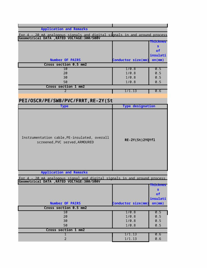
Cross section 1 mm21 1/1.13 0.62 1/1.13 0.6
PEI/PSCR/MS/HDPE/NC/SWA/HDPE,
RE-2Y(L)2Y4YSWA2Y PiMF
for 4 - 20 mA analogous signals and digital signals in and around process control with improved reduction of internal interferences, mainly used for direct burial, chemical, rodent and termite resistantGeometrical DATA ,RATED VOLTAGE:300/500V,Hydroca
Number OF PAIRS Conductor size(mm)Cross section 0.5 mm2
10 1/0.8 0.520 1/0.8 0.530 1/0.8 0.550 1/0.8 0.5
Cross section 1 mm22 1/1.13 0.6
PEI/OSCR/PVC/FRRT, RE-2Y(St)Yfl
RE-2Y(St)Yfl
Type Type designation
Instrumentation cable,PE-insulated,HDPE served,ARMOURED,laminated sheathed,polyamide
sheathed
Application and Remarks
Thicknessof
insulation(mm)
Type Type designation
Instrumentation cable,PE-insulated,Overall screened,PVC served
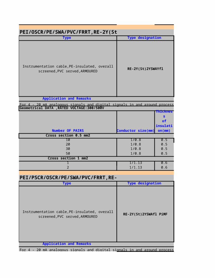
RE-2Y(St)Yfl
For RTD measurement in and around process control; used in dry and wet industrial locations, not recommended for direct burialGeometrical DATA ,RATED VOLTAGE:300/500V,flame ret
Number OF PAIRS Conductor size(mm)Cross section 0.5 mm2
10 1/0.8 0.520 1/0.8 0.530 1/0.8 0.550 1/0.8 0.5
Cross section 1 mm21 1/1.13 0.62 1/1.13 0.6
PEI/OSCR/PE/SWB/PVC/FRRT ,RE-2Y(
RE-2Y(St)2YQYfl
Instrumentation cable,PE-insulated,Overall screened,PVC served
Application and Remarks
Thicknessof
insulation(mm)
Type Type designation
Instrumentation cable,PE-insulated,Overall screened,PVC served,armoured

RE-2Y(St)2YQYfl
For RTD measurement in and around process control; indoor and outdoor use in dry and wet locations, for direct burial without agressive chemical substancesGeometrical DATA ,RATED VOLTAGE:300/500V,flame ret
Number OF PAIRS Conductor size(mm)Cross section 0.5 mm2
10 1/0.8 0.520 1/0.8 0.530 1/0.8 0.550 1/0.8 0.5
Cross section 1 mm21 1/1.13 0.62 1/1.13 0.6
PEI/TSCR/OSCR/PE/SWB/PVC/FRRT,
RE-2Y(St)2YQYfl TiMF
For RTD measurement in and around process control with a high quality reduction of internal interferences; indoor and outdoor use in dry and wet locations, for direct burial without agressive chemical substancesGeometrical DATA ,RATED VOLTAGE:300/500V,flame ret
Instrumentation cable,PE-insulated,Overall screened,PVC served,armoured
Application and Remarks
Thicknessof
insulation
(mm)
Type Type designation
Instrumentation cable,PE-insulated,Overall screened,PVC served,armoured
Application and Remarks

Number OF PAIRS Conductor size(mm)Cross section 0.5 mm2
10 1/0.8 0.520 1/0.8 0.530 1/0.8 0.550 1/0.8 0.5
Cross section 1 mm22 1/1.13 0.6
PEI/MS/HDPE/NC/SWA/HDPE ,RE-
RE-2Y(L)2Y4YSWA2Y
for RTD measurement in and around process control mainly used for direct burial, chemical, rodent and termite resistantGeometrical DATA ,RATED VOLTAGE:300/500V,Hydroca
Number OF PAIRS Conductor size(mm)Cross section 0.5 mm2
10 1/0.8 0.520 1/0.8 0.530 1/0.8 0.550 1/0.8 0.5
Cross section 1 mm21 1/1.13 0.62 1/1.13 0.6
Thicknessof
insulation
(mm)
Type Type designation
Instrumentation cable,PE-insulated,Polyamide screened,HDPE served,armoured,laminated sheath
Application and Remarks
Thicknessof
insulation
(mm)
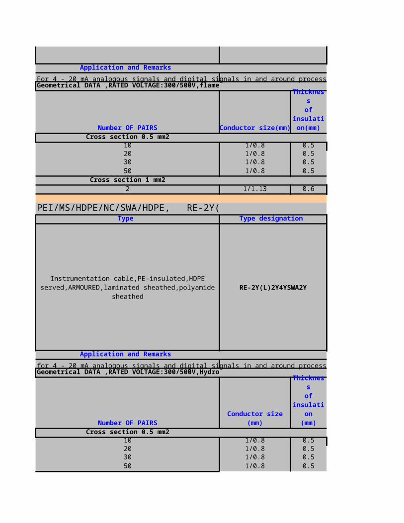
PEI/TSCR/MS/HDPE/NC/SWA/HDPE
RE-2Y(L)2Y4YSWA2Y TiMF
for RTD measurement in and around process control with high quality reduction of internal interferences, mainly used for direct burial, chemical, rodent and termite resistantGeometrical DATA ,RATED VOLTAGE:300/500V,Hydroca
Number OF PAIRS Conductor size(mm)Cross section 0.5 mm2
10 1/0.8 0.520 1/0.8 0.530 1/0.8 0.550 1/0.8 0.5
Cross section 1 mm22 1/1.13 0.6
PEI/OSCR/PVC/FRRT KCB, RT-2Y(
RT-2Y(St)Yfl KCB
Type Type designation
Instrumentation cable,PE-insulated,Polyamide screened,HDPE served,armoured,laminated sheath
Application and Remarks
Thicknessof
insulation
(mm)
Type Type designation
T/C Compensating cable,PE-insulated, overall screened,PVC served
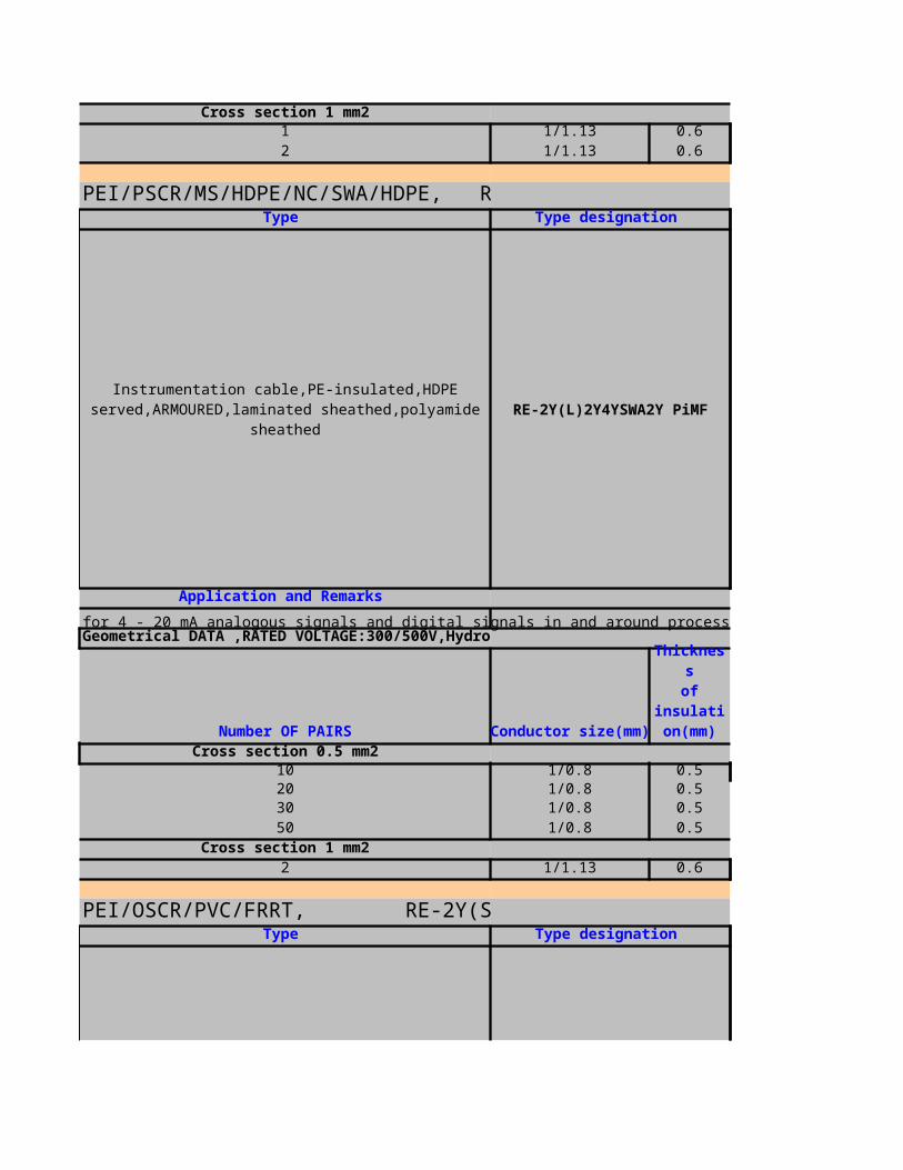
RT-2Y(St)Yfl KCB
For thermovoltage transmission of type K thermocouples in and around process control; indoor and outdoor use in dry and wet locations, not recommended for direct burialGeometrical DATA ,RATED VOLTAGE:300/500V,flame ret
Number OF PAIRS Conductor size(mm)Cross section 0.5 mm2
10 1/0.8 0.520 1/0.8 0.5
Cross section 1 mm21 1/1.29 0.5
PEI/OSCR/PE/SWB/PVC/FRRT KCB,
RT-2Y(St)2YQYfl KCB
For thermovoltage transmission of type K thermocouples in and around process control, indoor and outdoor use in dry and wet locations, for direct burial without agressive chemical substancesGeometrical DATA ,RATED VOLTAGE:300/500V,flame ret
T/C Compensating cable,PE-insulated, overall screened,PVC served
Application and Remarks
Thicknessof
insulation
(mm)
Type Type designation
T/C Compensating cable,PE-insulated, overall screened,PVC served,armoured
Application and Remarks

Number OF PAIRS Conductor size(mm)Cross section 0.5 mm2
10 1/0.8 0.520 1/0.8 0.5
Cross section 1 mm21 1/1.29 0.5
PEI/MS/HDPE/NC/SWA/HDPE KCB ,
RT-2Y(L)2Y4YSWA2Y KCB
For thermovoltage transmission of type K thermocouples in and around process contro, mainly used for for direct burial,chemical, rodent and termite resistantGeometrical DATA ,RATED VOLTAGE:300/500V,Hydroca
Number OF PAIRS Conductor size(mm)Cross section 0.5 mm2
10 1/0.8 0.520 1/0.8 0.5
Cross section 1 mm21 1/1.29 0.5
Thicknessof
insulation
(mm)
Type Type designation
T/C Compensating cable,PE-insulated,laminated sheathed,polyamide sheathed,armoured,HDPE served
Application and Remarks
Thicknessof
insulation
(mm)
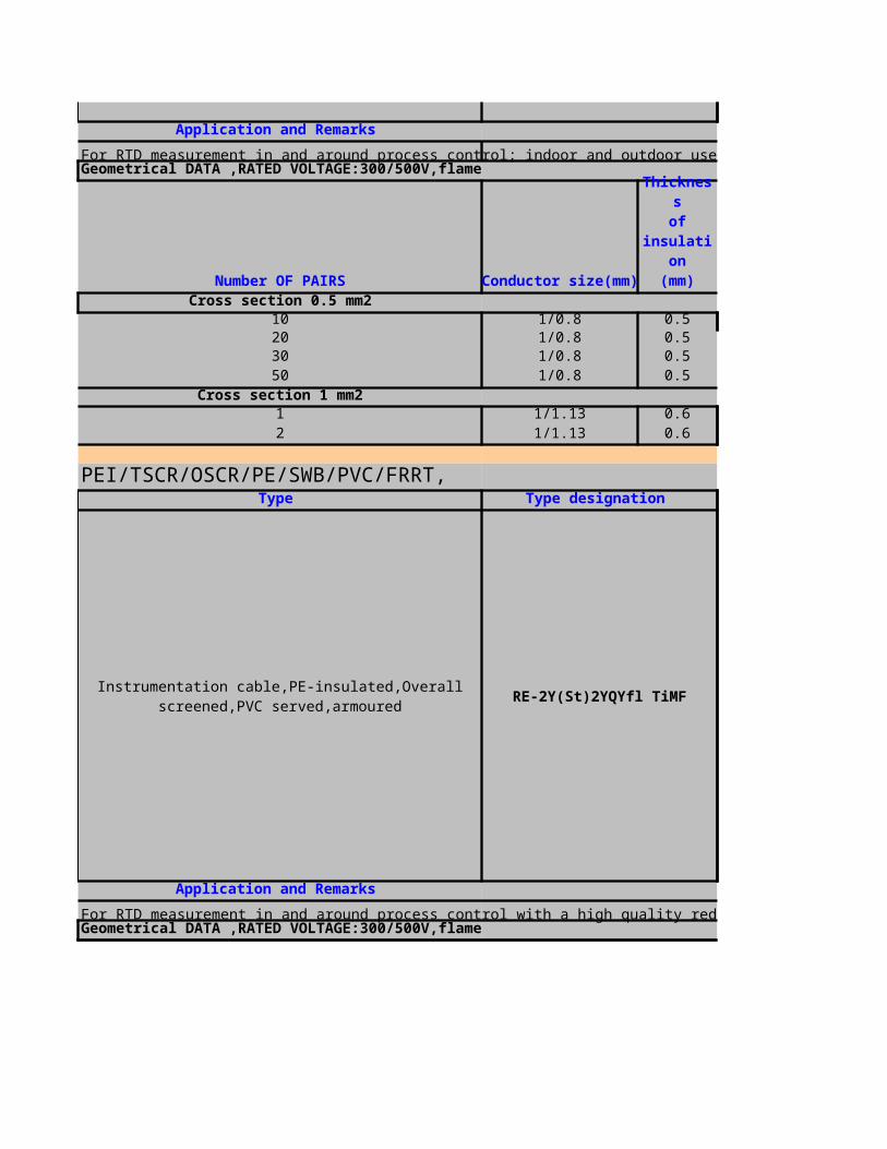
INSTRUMENTATION CABLE
For 4 - 20 mA analogous signals and digital signals in and around process control; indoor and outdoor use in dry and wet locations, not recommended for direct burial
overall diameter(mm)
1.2 14.41.3 18.81.3 22.51.5 28.5
0.8 6.40.8 7.6
Construction
1.Conductor:solid plain annealed copper wires with a cross section of 0.5 mm² or1.0 mm²2.polyethylene:type 03 acc. to BS 6234
3.aluminium bonded polyester tape over a tinned copper drain wire of 0.5 mm²
4.SHEATH:polyvinylchloride, TM1 acc. to BS 7655 section 4.1, black or blue
Thicknessof sheath(mm)
Construction
1.Conductor:solid plain annealed copper wires with a cross section of 0.5 mm² or 1.0 mm²
2.INSULATION:polyethylene, type 03 acc. to BS 6234
3.OVERALL SCREEN:aluminium bonded polyester tape over a tinned copper drain wire of 0.5 mm2
4.Sheath:polyvinylchloride, TM1 acc. to BS 7655 sector 4.1, green or blue

For 4 - 20 mA analogous signals and digital signals in and around process control with improved reduction of internal interferences; indoor and outdoor use in dry and wet locations, not recommended for direct burial
overall diameter(mm)
1.2 16.81.3 22.31.5 27.22 35.1
1.1 11.9
For 4 - 20 mA analogous signal and digital signals in and around process control; indoor and outdoor use in dry and wet locations, for direct burial without agressive chemical substances
DIA OVERALL BEDDING
1.2 14.41.3 18.81.3 22.31.5 28.5
0.8 6.40.8 8
Thicknessof sheath(mm)
Construction
1.Conductor:solid plain annealed copper wires with a cross section of 0.5 mm² or 1.0 mm²
2.INSULATION:polyethylene, type 03 acc. to BS 6234
3.OVERALL SCREEN:aluminium bonded polyester tape over a tinned copper drain wire of 0.5 mm2
4.Sheath:polyvinylchloride, TM1 acc. to BS 7655 sector 4.1, BLACK or blue
5.Armour:galvanized steel wire braid with at least 80% coverage over a stranded tinned copper drain wire with the same cross section as the conductors
Thicknessof BEDDING(mm)

For 4 - 20 mA analogous signals and digital signals in and around process control; indoor and outdoor use in dry and wet locations, for direct burial without agressive chemical substances
DIA OVERALL BEDDING
1.2 14.41.3 18.81.3 22.51.5 28.5
0.8 6.40.8 8.1
For 4 - 20 mA analogous signals and digital signals in and around process control with improved reduction of internal interferences, indoor and outdoor use in dry and wet locations, for direct burial without agressive chemical substances
Construction
1.Conductor:solid plain annealed copper wires with a cross section of 0.5 mm² or 1.0 mm²
2.INSULATION:polyethylene, type 03 acc. to BS 6234
3.OVERALL SCREEN:aluminium bonded polyester tape over a tinned copper drain wire of 0.5 mm2
4.Sheath:polyvinylchloride, TM1 acc. to BS 7655 sector 4.1, green or blue
5.Armour:galvanized round steel wires acc. to BS 1442
Thicknessof BEDDING(mm)
Construction
1.Conductor:solid plain annealed copper wires with a cross section of 0.5 mm² or 1.0 mm²
2.INSULATION:polyethylene, type 03 acc. to BS 6234
3.OVERALL SCREEN:aluminium bonded polyester tape over a tinned copper drain wire of 0.5 mm2
4.Sheath:polyvinylchloride, TM1 acc. to BS 7655 sector 4.1, green or blue
5.Armour:galvanized round steel wires acc. to BS 1442
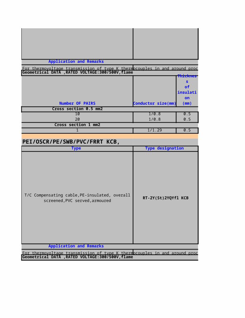
DIA OVERALL BEDDING
1.2 16.91.3 22.31.5 27.22 35.1
1.1 11.9
For 4 - 20 mA analogous signals and digital signals in and around process control with improved reduction of internal interferences, indoor and outdoor use in dry and wet locations, for direct burial without agressive chemical substances
DIA OVERALL BEDDING
1.2 16.91.3 22.31.5 27.22 35.1
1.1 11.8
Thicknessof BEDDING(mm)
Construction
1.Conductor:solid plain annealed copper wires with a cross section of 0.5 mm² or 1.0 mm²
2.INSULATION:polyethylene, type 03 acc. to BS 6234
3.OVERALL SCREEN:aluminium bonded polyester tape over a tinned copper drain wire of 0.5 mm2
4.Sheath:polyvinylchloride, TM1 acc. to BS 7655 sector 4.1, black or blue
5.Armour:galvanized steel wire braid with at least 80% coverage over a stranded tinned copper drain wire with the same cross section as the conductors
Thicknessof BEDDING(mm)
Construction
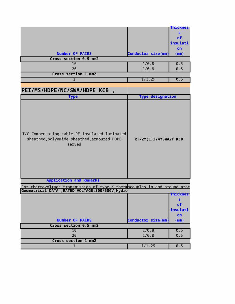
For 4 - 20 mA analogous signals and digital signals in and around process control with improved reduction of internal interferences, indoor and outdoor use in dry and wet locations, for direct burial with agressive chemical substances
Thickness of lead sheath(mm) dia overall lead(mm)
1.1 17.11.3 21.91.4 25.61.5 31.9
1.1 9.31.1 10.3
1.Conductor:solid plain annealed copper wires with a cross section of 0.5 mm² or 1.0 mm²
2.INSULATION:polyethylene, type 03 acc. to BS 6234
3.OVERALL SCREEN:aluminium bonded polyester tape over a tinned copper drain wire of 0.5 mm2
4.Sheath:polyvinylchloride, TM1 acc. to BS 7655 sector 4.1, Green or blue
5.Armour:galvanized round steel wires acc. to BS 1442
6.Metal sheath:lead alloy, type E acc. to BS 801
Construction
1.Conductor:solid plain annealed copper wires with a cross section of 0.5 mm² or 1.0 mm²
2.INSULATION:polyethylene, type 03 acc. to BS 6234
3.OVERALL SCREEN:aluminium bonded polyester tape over a tinned copper drain wire of 0.5 mm2
4.Sheath:polyvinylchloride, TM1 acc. to BS 7655 sector 4.1, Green or blue
5.Armour:galvanized round steel wires acc. to BS 1442
6.Metal sheath:lead alloy, type E acc. to BS 801
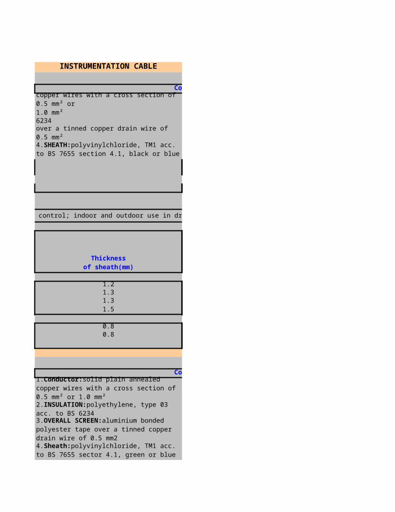
For 4 - 20 mA analogous signals and digital signals in and around process control with improved reduction of internal interferences, indoor and outdoor use in dry and wet locations, for direct burial with agressive chemical substances
Thickness of lead sheath(mm) dia overall lead(mm)
1.2 19.81.4 25.61.5 30.51.8 39
1.1 14.7
for 4 - 20 mA analogous signals and digital signals in and around process control mainly used for direct burial, chemical,rodent and termite resistant
Dia under armour(mm)
1 16.41 20.61 241 29.7
Construction
1.Conductor:solid plain annealed copper wires with a cross section of 0.5 mm² or 1.0 mm²
2.INSULATION:polyethylene, type 03 acc. to BS 6234
3.Protective sheath:heat stabilized polyamide, thickness: 0.5 mm, coloured black
4.Outer sheath:high density polyethylene, coloured black
5.Armour:galvanized round steel wires acc. to BS 1442
thickness of HDPE of laminated sheath(mm)
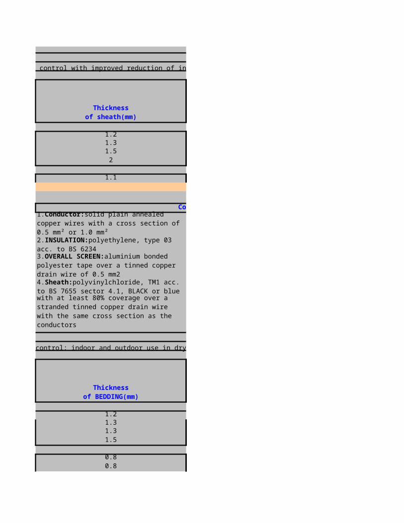
1 9.11 10
for 4 - 20 mA analogous signals and digital signals in and around process control with improved reduction of internal interferences, mainly used for direct burial, chemical, rodent and termite resistant
Dia under armour(mm)
1 19.51 241 28.31 35.2
1 13.8
Construction
1.Conductor:solid plain annealed copper wires with a cross section of 0.5 mm² or 1.0 mm²
2.INSULATION:polyethylene, type 03 acc. to BS 6234
3.Protective sheath:heat stabilized polyamide, thickness: 0.5 mm, coloured black
4.Outer sheath:high density polyethylene, coloured black
5.Armour:galvanized round steel wires acc. to BS 1442
6.Colour code:black/blue, numbered by tape acc. to BS 5308
7.Pair screen:aluminium bonded polyester tape over a tinned copper drain wire of0.5 mm² with two separator tapes over the screening tape
thickness of HDPE of laminated sheath(mm)
Construction
1.Conductor:solid plain annealed copper wires with a cross section of 0.5 mm² or 1.0 mm²
2.INSULATION:polyethylene, type 03 acc. to BS 6234
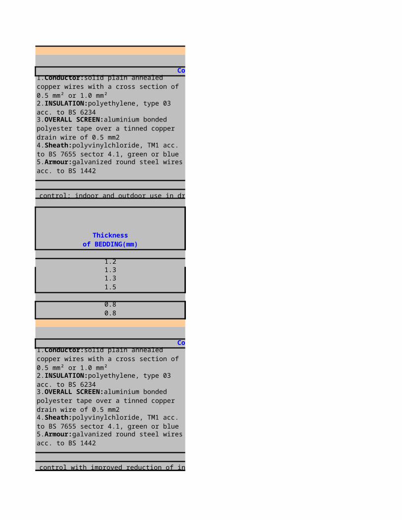
For RTD measurement in and around process control; used in dry and wet industrial locations, not recommended for direct burial
thickness of Sheath(mm)
1.2 16.41.3 21.21.5 25.91.7 32.8
0.8 71.1 11.6
3.Colour code:black, white, red, continuously numbered for multitriples
4.Overall screen:screen of aluminium bonded polyester tape over a tinned copper drain wire of 0.5 mm²
5.Sheath:polyvinylchloride, TM1 acc. to BS 7655 section 4.1, black or blue (for intrinsically safe systems)
OverallDIA (MM)
Construction
1.Conductor:solid plain annealed copper wires with a cross section of 0.5 mm² or 1.0 mm²
2.INSULATION:polyethylene, type 03 acc. to BS 6234
3.Colour code:black, white, red, continuously numbered for multitriples
4.Overall screen:aluminium bonded polyester tape over a tinned copper drain wire of 0.5 mm²
5.Armour:galvanized steel wire braid with at least 80% coverage over a strandedtinned copper drain wire with the same cross section as the conductors
6.Sheath:polyvinylchloride, TM1 acc. to BS 7655 section 4.1, black or blue (forintrinsically safe systems)
7.Bedding:polyethylene, type 03 acc. to BS 6234, black
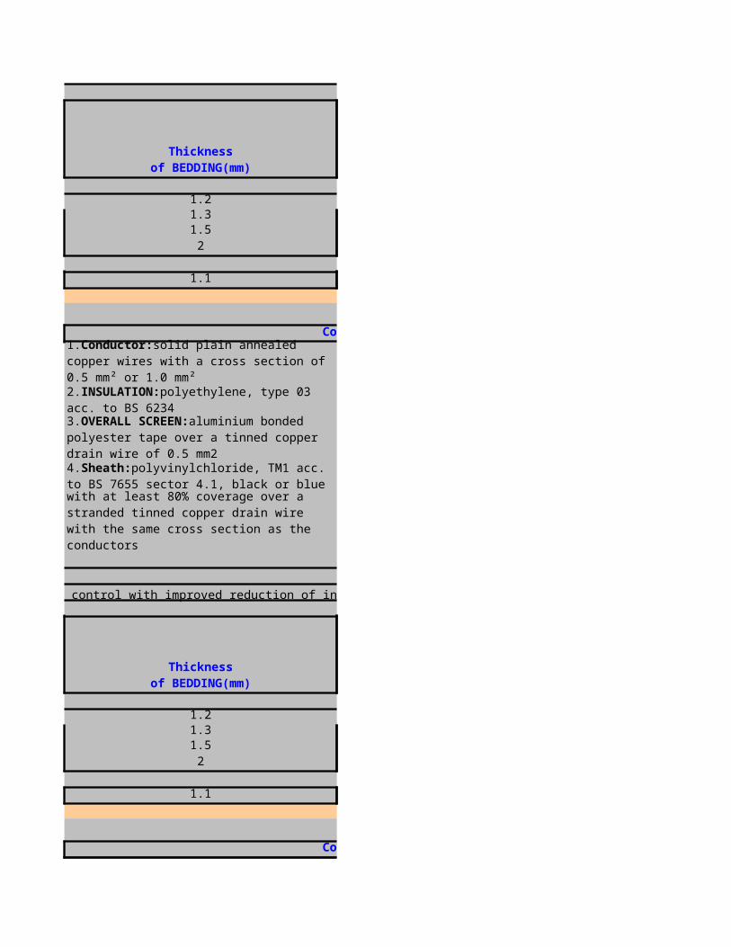
For RTD measurement in and around process control; indoor and outdoor use in dry and wet locations, for direct burial without agressive chemical substances
1.2 16.41.3 21.21.5 25.91.7 32.8
0.8 71.1 11.6
For RTD measurement in and around process control with a high quality reduction of internal interferences; indoor and outdoor use in dry and wet locations, for direct burial without agressive chemical substances
thickness of bedding(mm)
dia over bedding(mm)
Construction
1.Conductor:solid plain annealed copper wires with a cross section of 0.5 mm² or 1.0 mm²
2.INSULATION:polyethylene, type 03 acc. to BS 6234
3.Colour code:black, white, red, numbered by tape
4.Overall screen:aluminium bonded polyester tape over a tinned copper drain wire of 0.5 mm²
5.Armour:galvanized steel wire braid with at least 80% coverage over a strandedtinned copper drain wire with the same cross section as the conductors
6.Sheath:polyvinylchloride, TM1 acc. to BS 7655 section 4.1, black or blue (forintrinsically safe systems)
7.Bedding:polyethylene, type 03 acc. to BS 6234, black
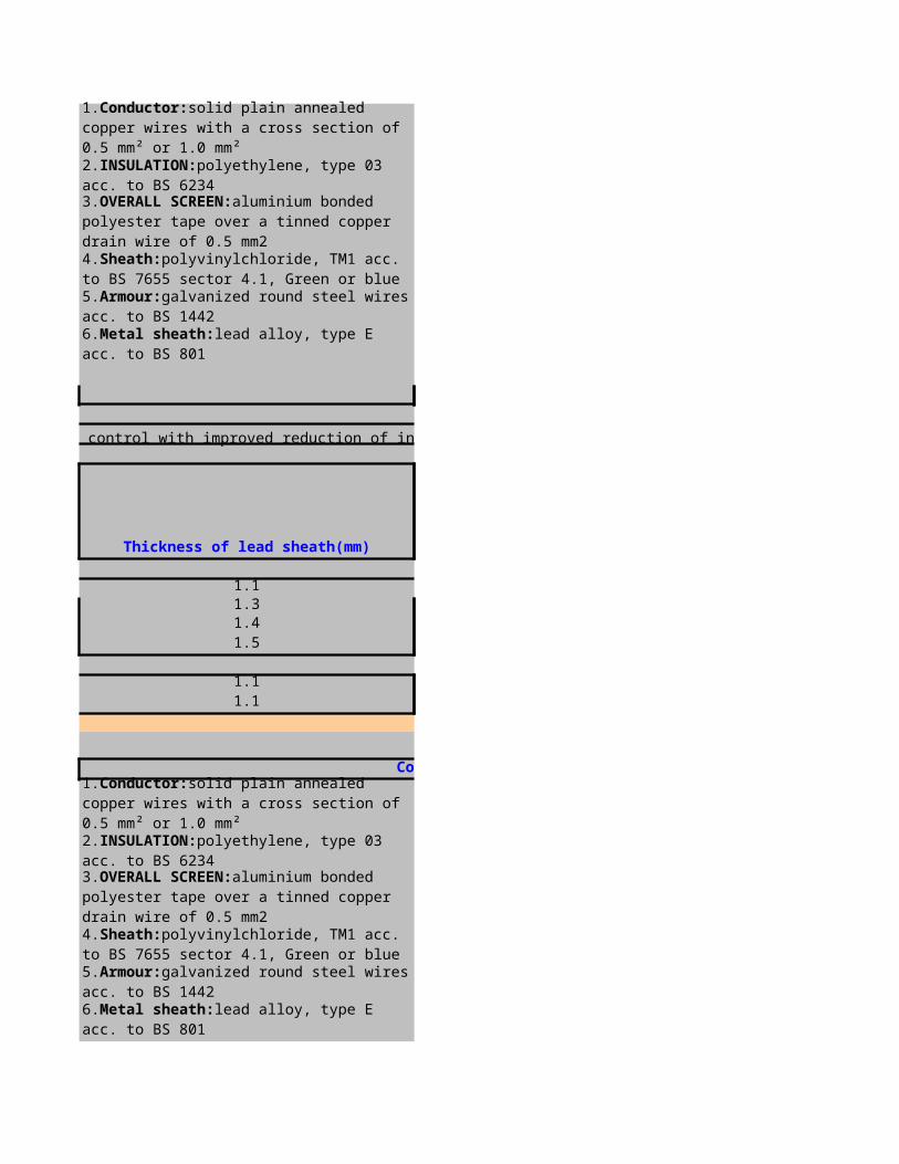
1.3 19.51.5 25.51.7 30.92 39.3
1.2 13.3
for RTD measurement in and around process control mainly used for direct burial, chemical, rodent and termite resistant
dia under armour(mm)
1 18.31 22.91 271 33.5
1 9.41 13.7
thickness of bedding(mm)
dia over bedding(mm)
Construction
1.Conductor:solid plain annealed copper wires with a cross section of 0.5 mm² or 1.0 mm²
2.INSULATION:polyethylene, type 03 acc. to BS 6234
3.Colour code:black, white, red, continuously numbered for multitriples
4.Protective sheath:heat stabilized polyamide, thickness: 0.5 mm, coloured black
5.Armour:galvanized round steel wires acc. to BS 1442
6.Outer sheath:high density polyethylene, coloured black
Thickness of HDPE of the laminated sheath(mm)
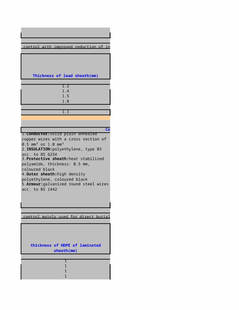
for RTD measurement in and around process control with high quality reduction of internal interferences, mainly used for direct burial, chemical, rodent and termite resistant
dia under armour(mm)
1 211 26.51 31.61 39.4
1 15.2
Construction
1.Conductor:solid plain annealed copper wires with a cross section of 0.5 mm² or 1.0 mm²
2.INSULATION:polyethylene, type 03 acc. to BS 6234
3.Colour code:black, white, red, numbered by tape
4.Protective sheath:heat stabilized polyamide, thickness: 0.5 mm, coloured black
5.Armour:galvanized round steel wires acc. to BS 1442
6.Outer sheath:high density polyethylene sheath, coloured black
Thickness of HDPE of the laminated sheath(mm)
Construction
1.Conductor:solid compensating wires type KCB acc. to IEC 584 part 3 with a cross section of 0.5 mm² or 1.3 mm²
2.INSULATION:polyethylene, type 03 acc. to BS 6234
3.Colour code:(+) green, (-) white, continuously numbered for multipair cables
4.Overall screen:aluminium bonded polyester tape over a tinned copper drain wire of 0.5 mm²
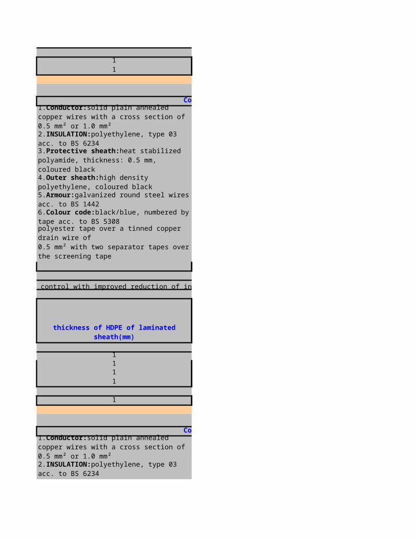
For thermovoltage transmission of type K thermocouples in and around process control; indoor and outdoor use in dry and wet locations, not recommended for direct burial
Thickness of sheath(mm) overall diameter(mm)
1.2 14.41.3 18.8
1 6.9
For thermovoltage transmission of type K thermocouples in and around process control, indoor and outdoor use in dry and wet locations, for direct burial without agressive chemical substances
5.Sheath:polyvinylchloride, TM1 acc. to BS 7655 section 4.1, green or blue with agreen tracer (for intrinsically safe systems)
Construction
1.Conductor:solid compensating wires type KCB acc. to IEC 584 part 3 with a cross section of 0.5 mm² or 1.3 mm²
2.INSULATION:polyethylene, type 03 acc. to BS 6234
3.Colour code:(+) green, (-) white, continuously numbered for multipair cables
4.Bedding:polyethylene, type 03 acc. to BS 6234, black
5.Armour:galvanized steel wire braid with at least 80% coverage over a strandedtinned copper drain wire with the same cross section as the conductors
6.Sheath:polyvinylchloride, TM1 acc. to BS 7655 section 4.1, green or blue with agreen tracer (for intrinsically safe systems)
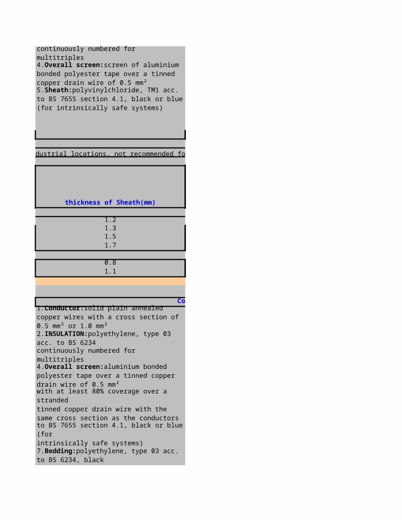
Thickness of bedding(mm) Dia over bedding
1.2 14.41.3 18.8
0.8 6.4
For thermovoltage transmission of type K thermocouples in and around process contro, mainly used for for direct burial,chemical, rodent and termite resistant
Dia under armour(mm)
1 16.41 20.6
1 9.1
Construction
1.Conductor:solid compensating wires type KCB acc. to IEC 584 part 3 with a cross section of 0.5 mm² or 1.3 mm²
2.INSULATION:polyethylene, type 03 acc. to BS 6234
3.Colour code:(+) green, (-) white, continuously numbered for multipair cables
4.Protective sheath:heat stabilized polyamide, thickness: 0.5 mm, coloured black
5.Armour:galvanized round steel wires acc. to BS 1442
6.Outer sheath:high density polyethylene, coloured green
Thickness of HDPE of the laminated sheath(mm)

For 4 - 20 mA analogous signals and digital signals in and around process control with improved reduction of internal interferences; indoor and outdoor use in dry and wet locations, not recommended for direct burial
0.3 1.6 19.80.3 1.7 24.40.3 1.7 270.3 2 34.2
0.3 1.3 10.30.3 1.4 13.4
ARMOUR WIREDIA(MM)
THICKN.SHEATH(
MM)Overall
DIA (MM)
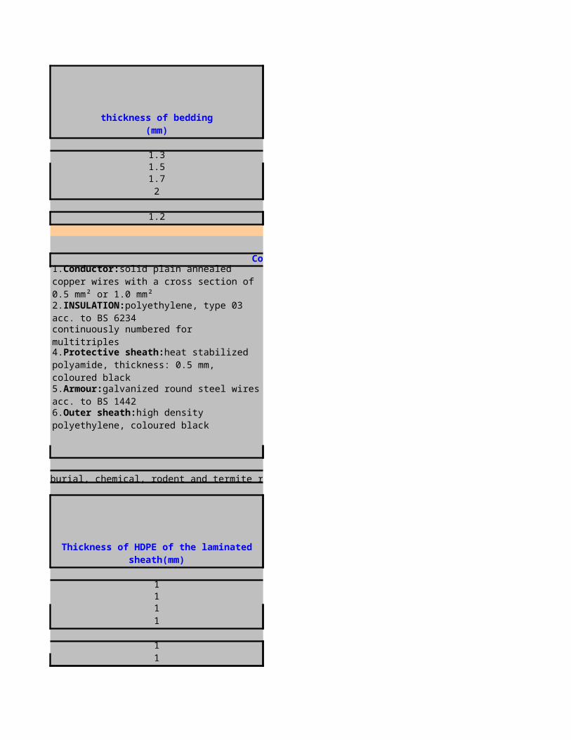
1.25 1.6 20.11.6 1.7 25.41.6 1.8 29.31.6 2 35.7
0.9 1.3 10.80.9 1.4 12.4
For 4 - 20 mA analogous signals and digital signals in and around process control with improved reduction of internal interferences, indoor and outdoor use in dry and wet locations, for direct burial without agressive chemical substances
ARMOUR WIREDIA(MM)
THICKN.SHEATH(
MM)Overall
DIA (MM)
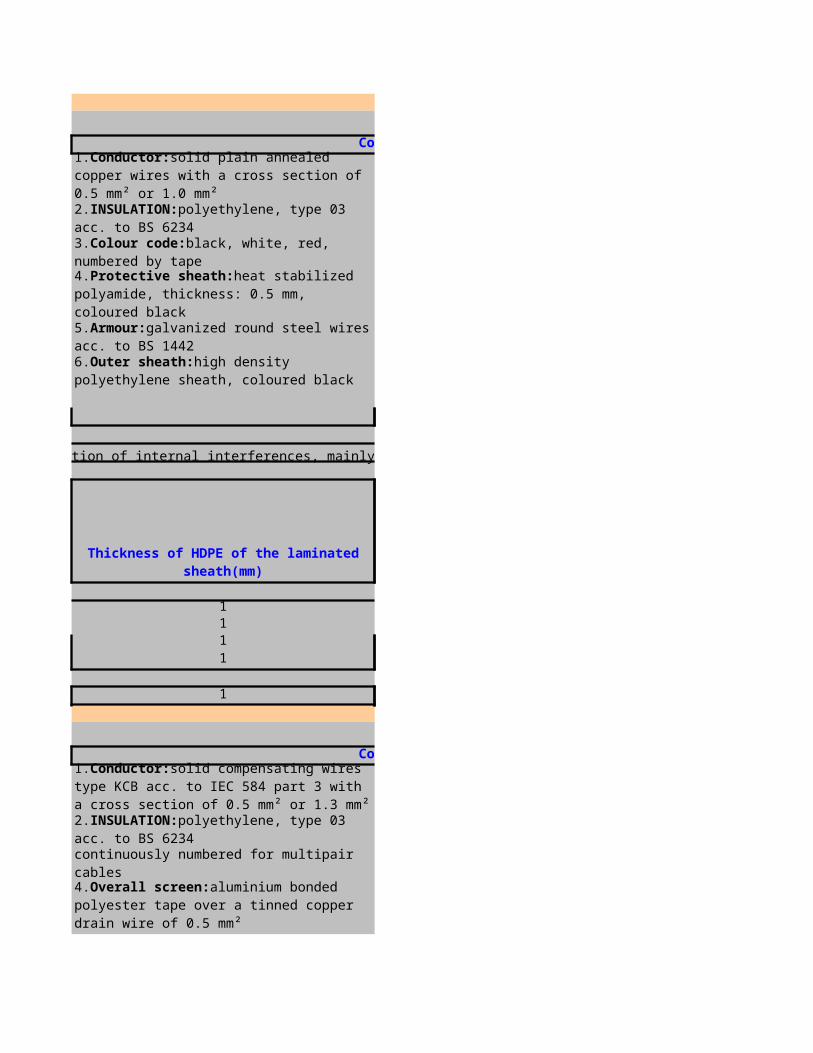
1.25 1.7 22.81.6 1.8 29.11.6 1.9 34.22 2.2 43.5
0.9 1.5 16.7
For 4 - 20 mA analogous signals and digital signals in and around process control with improved reduction of internal interferences, indoor and outdoor use in dry and wet locations, for direct burial without agressive chemical substances
0.3 1.7 21.70.3 1.8 27.20.3 1.9 32.30.3 2.2 40.8
0.3 1.5 16.1
ARMOUR WIREDIA(MM)
THICKN.SHEATH(
MM)Overall
DIA (MM)
ARMOUR WIREDIA(MM)
THICKN.SHEATH(
MM)Overall
DIA (MM)
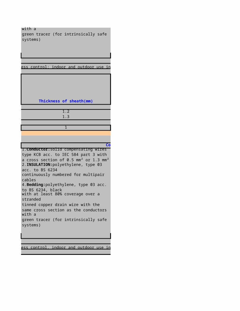
For 4 - 20 mA analogous signals and digital signals in and around process control with improved reduction of internal interferences, indoor and outdoor use in dry and wet locations, for direct burial with agressive chemical substances
1.6 1.7 25.71.6 1.8 30.71.6 1.9 34.62 2.1 42.5
0.9 1.4 15.50.9 1.5 16.9
ARMOUR WIREDIA(MM)
THICKN.SHEATH(
MM)Overall
DIA (MM)

For 4 - 20 mA analogous signals and digital signals in and around process control with improved reduction of internal interferences, indoor and outdoor use in dry and wet locations, for direct burial with agressive chemical substances
1.6 1.7 28.42 1.9 35.82 2 40.9
2.5 2.3 51.4
1.25 1.6 22
1.6 1.7 231.6 1.8 27.41.6 1.9 311.6 2.1 37.4
ARMOUR WIREDIA(MM)
THICKN.SHEATH(
MM)Overall
DIA (MM)
ARMOUR WIREDIA(MM)
THICKN.SHEATH
(MM)Overall
DIA (MM)

0.9 1.4 13.70.9 1.4 14.8
for 4 - 20 mA analogous signals and digital signals in and around process control with improved reduction of internal interferences, mainly used for direct burial, chemical, rodent and termite resistant
1.6 1.7 27.31.6 1.8 30.81.6 1.9 35.32 2.1 43.4
1.25 1.6 19.9
ARMOUR WIREDIA(MM)
THICKN.SHEATH(
MM)Overall
DIA (MM)

0.3 1.6 20.90.3 1.7 25.90.3 1.9 310.4 2 38.6
0.3 1.3 10.90.3 1.5 15.8
For RTD measurement in and around process control with a high quality reduction of internal interferences; indoor and outdoor use in dry and wet locations, for direct burial without agressive chemical substances
Armour wire dia(mm)
sheath thickness
(mm)
overall diameter(
mm)
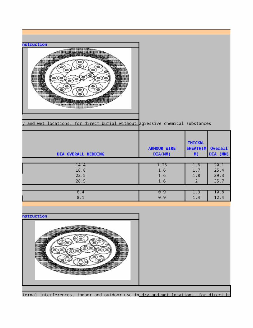
0.3 1.7 24.20.3 1.8 29.40.4 2 36.70.4 2.2 45.5
0.3 1.5 17.6
1.6 1.7 24.91.6 1.8 29.71.6 1.9 342 2.1 41.7
0.9 1.4 141.25 1.6 19.4
Armour wire dia(mm)
sheath thickness
(mm)
overall diameter(
mm)
Armour wire dia(mm)
sheath thickness
(mm)
overall diameter(
mm)
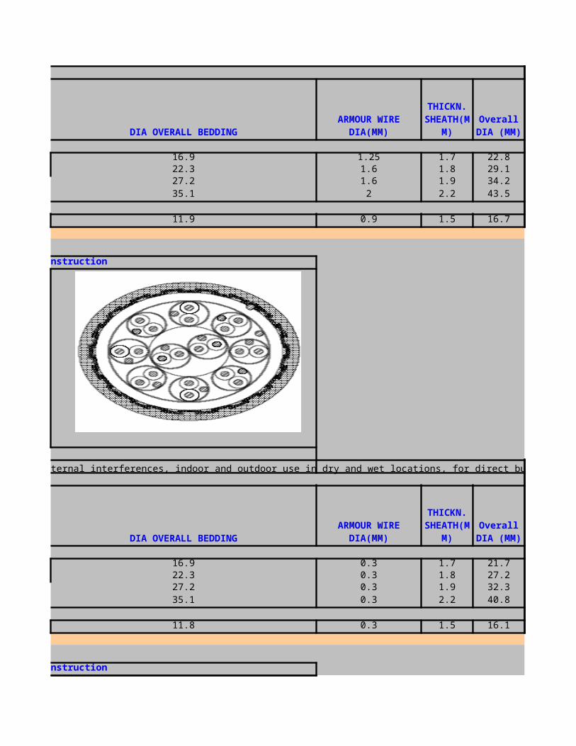
1.6 1.8 27.81.6 1.9 33.52 2.1 39.82 2.3 48
1.25 1.6 20.9
Armour wire dia(mm)
sheath thickness
(mm)
overall diameter(
mm)
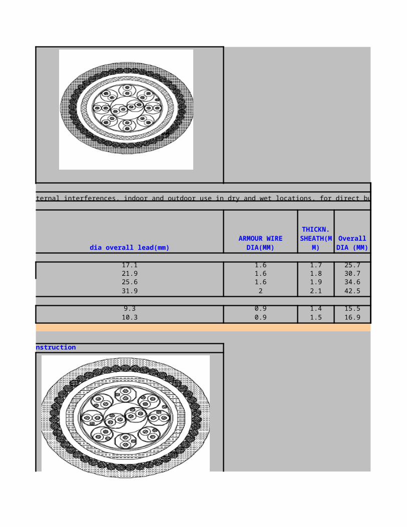
0.3 1.6 19.80.3 1.7 24.4
0.3 1.3 10.3
1.6 1.7 231.6 1.8 27.4
0.9 1.4 13.7
Armour Wire dia(mm)
Sheath thickness
(mm)
Overall diameter(
mm)
Armour Wire dia(mm)
Sheath thickness
(mm)
Overall diameter(
mm)
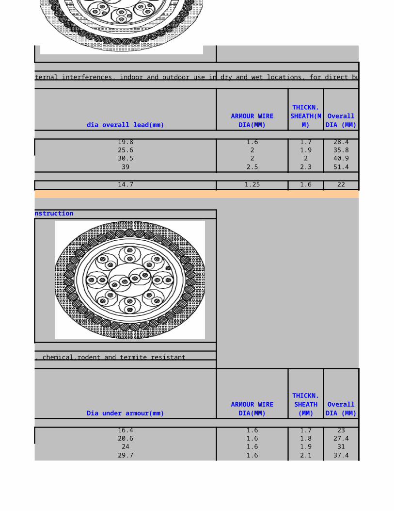
FIBER OPTIC CABLE
Cables with ULSZH Jacket comply with the following standards:● Fire propagation IEC 332-1 & 332-3● Flammability IEC 1034● Smoke Emission IEC 1034● Acid gas Emission IEC 754-1● Toxicity NES 713● Water Absorption IEC 811-1-3(<2mg/cm2 10 days @ 70 c)● Mechanical Properties (Tested acc. To IEC 794-1)Operating Temperature: -40 to + 60 c
HOME PAGENEXT PAGE
PREVIOUS PAGE

ID5C5VDE Code: I-DQ(ZN)H(SR)HArmoured fibre optic cable with functional integrity E30Applications and features:Safety cable for indoor and outdoor use in tunnels, undergrounds or other applications where functional integrity under fire conditions is a must. Can be used in ducts or on cable traysHalogen-free, flame-retardant outer sheath
Mechanical Specifications
ID5C5Number of fibres from 2 to 24
Tube diameter (mm) 3.5Cable diameter, approx. (mm) 11.5Outer sheath thickness (mm) 1.5Weight, approx. (kg per km) 140
Tested according to IEC 60794-1Flame-retardant according to IEC 60332-1 & 60332-3-24
Halogen-free according to IEC 60754-2Low-smoke according to IEC 61034-1/2
Functional integrity according to DIN 4102 part 12
UD500VDE Code: A/I-DQ(ZN)HUnitube indoor/outdoor fibre optic cableApplications and features:Universal cable for indoor and outdoor use in ducts or on cable trays.HLFR (halogen-free, flame-retardant) sheath
Mechanical Specifications
UD500Number of fibres from 2 to 24
Tube diameter (mm) 3.5Cable diameter, approx. (mm) 8Outer sheath thickness (mm) 1.5Weight, approx. (kg per km) 65
Sheath colour BlackTested according to IEC 60794-1
Flame-retardant according to IEC 60332-1 & 60332-3-24Halogen-free according to IEC 60754-2Low-smoke according to IEC 61034-1/2
XD500VDE Code: A/I-DQ(ZN)HNon-metallic indoor/outdoor fibre optic cableApplications and features:Universal cable for indoor and outdoor use in ducts or on cable trays.Halogen-free, flame-retardant sheath
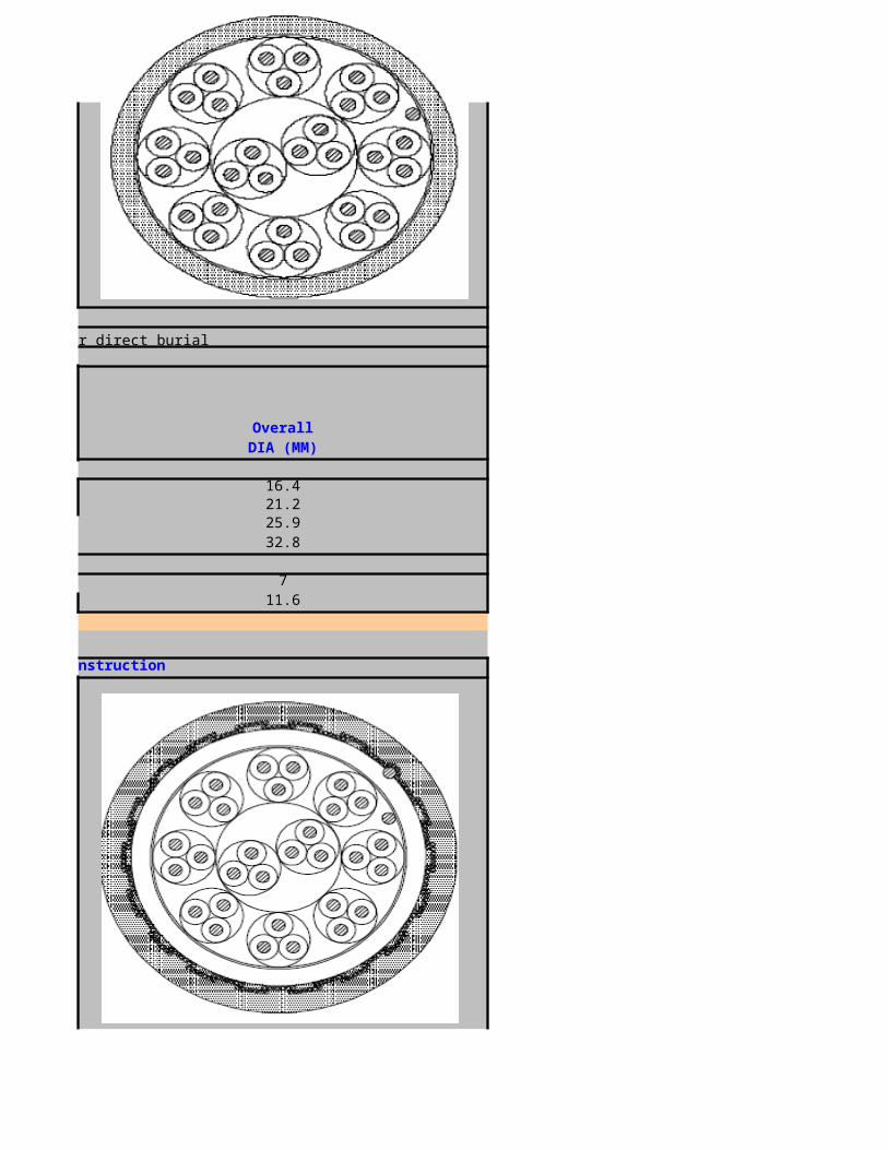
Mechanical Specifications
XD500Number of fibres up to 36 up to 60Number of tubes 6 5
Tube diameter (mm) 2.1 2.8Cable diameter, approx. (mm) 10.5 12Outer sheath thickness (mm) 1.5 1.5Weight, approx. (kg per km) 110 130
Tested according to IEC 60794-1 IEC 60794-1Flame-retardant according to IEC 60332-1 & 60332-3-24 IEC 60332-1 & 60332-3-24
Halogen-free according to IEC 60754-2 IEC 60754-2Low-smoke according to IEC 61034-1/2 IEC 61034-1/2
UD100VDE Code: A-DQ(ZN)2YUnitube outdoor fibre optic cableApplications and features:Outdoor cable for use in ducts or on cable trays.polyethylene outer sheath
Mechanical Specifications
UD100Number of fibres from 2 to 24
Tube diameter (mm) 3.5Cable diameter, approx. (mm) 8Outer sheath thickness (mm) 1.5Weight, approx. (kg per km) 50
Tested according to IEC 60794-1
UDG10VDE Code: A-DQ(ZNB)2YUnitube outdoor fibre optic cable, rodent resistantApplications and features:Outdoor cable for use in ducts or on cable trayspolyethylene outer sheath is used for outdoor applicationHLFR (halogen-free, flame-retardant) sheath for indoor/outdoor application
Mechanical Specifications
UDG10Number of fibres from 2 to 24
Tube diameter (mm) 3.5Cable diameter, approx. (mm) 9Outer sheath thickness (mm) 1.5Weight, approx. (kg per km) 65
Tested according to IEC 60794-1
LF100VDE Code: A-DF2YNon-metallic outdoor fibre optic cableApplications and features:Outdoor, non-metallic structure,Suitable for duct installation by pulling or blowingPE/HLFR (halogen-free, flame-retardant) sheath can be used
Mechanical Specifications

LF100Number of fibres up to 36 up to 60Number of tubes 6 5
Tube diameter (mm) 2.1 2.8Cable diameter, approx. (mm) 10 11Outer sheath thickness (mm) 1.5 1.5Weight, approx. (kg per km) 80 110
Tested according to IEC 60794-1 IEC 60794-1
LD100VDE Code: A-DQ2YNon-metallic outdoor fibre optic cableApplications and features:Outdoor, non-metallic structure,Suitable for duct installation by pulling or blowing,Longitudinally water blocked with swelling elements,Loose tube, fully filled with thixotropic water-blocking gelPE/HLFR (halogen-free, flame-retardant) sheath can be used
Mechanical Specifications
LD100Number of fibres up to 36 up to 60Number of tubes 6 5
Tube diameter (mm) 2.1 2.8Cable diameter, approx. (mm) 10 11Outer sheath thickness (mm) 1.5 1.5Weight, approx. (kg per km) 80 90
Tested according to IEC 60794-1 IEC 60794-1
XF100VDE Code: A-DF(ZN)2YNon-metallic outdoor fibre optic cableApplications and features:Outdoor, non-metallic structure,Suitable for duct installation by pulling or blowing,Longitudinally water blocked with gel,Loose tube, fully filled with thixotropic water-blocking gelPE/HLFR (halogen-free, flame-retardant) sheath can be used
Mechanical Specifications
XF100Number of fibres up to 36 up to 60Number of tubes 6 5
Fibre per tube (max.) 6 12Tube diameter (mm) 2.1 2.8
Cable diameter, approx. (mm) 11 12Outer sheath thickness (mm) 1.5 1.5Weight, approx. (kg per km) 95 115
Tested according to IEC 60794-1 IEC 60794-1
XD100VDE Code: A-DQ(ZN)2YNon-metallic outdoor fibre optic cableApplications and features:- Outdoor, non-metallic structure,Suitable for duct installation by pulling or blowing,Longitudinally water blocked with swelling elements,Loose tube, fully filled with thixotropic water-blocking gelPE/HLFR (halogen-free, flame-retardant) sheath can be used
Mechanical Specifications
XD100
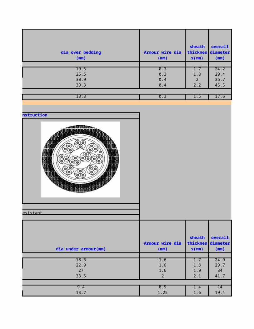
Number of fibres up to 36 up to 60Number of tubes 6 5
Fibre per tube (max.) 6 12Tube diameter (mm) 2.1 2.8
Cable diameter, approx. (mm) 11 12Outer sheath thickness (mm) 1.5 1.5Weight, approx. (kg per km) 90 105
Tested according to IEC 60794-1 IEC 60794-1
XFG10VDE Code: A-DF(ZNB)2YNon-metallic outdoor fibre optic cable, rodent resistantApplications and features:Outdoor, non-metallic structure,Rodent resistant,High pulling force,Suitable for duct installation by pulling or blowing,Longitudinally water blocked with gel,Loose tube, fully filled with thixotropic water-blocking gelPE/HLFR (halogen-free, flame-retardant) sheath can be usedMechanical Specifications
XFG10Number of fibres up to 36 up to 60Number of tubes 6 5
Fibre per tube (max.) 6 12Tube diameter (mm) 2.1 2.8
Cable diameter, approx. (mm) 12 13Outer sheath thickness (mm) 1.5 1.5Weight, approx. (kg per km) 115 140
Tested according to IEC 60794-1 IEC 60794-1
XDG10VDE Code: A-DQ(ZN)B2YNon-metallic outdoor fibre optic cable, rodent resistantApplications and features:Outdoor, non-metallic structure,Rodent resistant,High pulling force,Suitable for duct installation by pulling or blowing,Longitudinally water blocked with swelling elements,Loose tube, fully filled with thixotropic water-blocking gelPE/HLFR (halogen-free, flame-retardant) sheath can be used
Mechanical Specifications
XDG10Number of fibres up to 36 up to 60Number of tubes 6 5
Fibre per tube (max.) 6 12Tube diameter (mm) 2.1 2.8
Cable diameter, approx. (mm) 11.5 13Outer sheath thickness (mm) 1.5 1.5Weight, approx. (kg per km) 105 125
Tested according to IEC 60794-1 IEC 60794-1
XF200VDE Code: A-DF(ZN)(L)2YOutdoor fibre optic cable with aluminium moisture barrierApplications and features:Outdoor structure, with aluminium moisture barrier,Suitable for duct installation by pulling or blowing,Longitudinally water blocked with gel,Loose tube, fully filled with thixotropic water-blocking gelPE/ALUMINIUM LAMINATED TAPE(ALUPE) Can be used as outer sheath
Mechanical Specifications

XF200Number of fibres up to 36 up to 60Number of tubes 6 5
Fibre per tube (max.) 6 12Tube diameter (mm) 2.1 2.8
Cable diameter, approx. (mm) 11 13Outer sheath thickness (mm) 1.5 1.5Weight, approx. (kg per km) 115 140
Tested according to IEC 60794-1 IEC 60794-1
UDC10VDE Code: A-DQ(ZN)(SR)2YArmoured unitube fibre optic cableApplications and features:Outdoor cable with corrugated steel tape armour for direct burial and rodent protection,Longitudinally water blocked,Central loose tube, fully filled with thixotropic water-blocking gelPE/HLFR (halogen-free, flame-retardant) sheath can be used
Mechanical Specifications
UDC10Number of fibres from 2 to 24
Tube diameter (mm) 3.5Cable diameter, approx. (mm) 10.5Outer sheath thickness (mm) 1.5Weight, approx. (kg per km) 90
Tested according to IEC 60794-1
UD1C1VDE Code: A-DQ(ZN)2Y(SR)2YArmoured unitube fibre optic cableApplications and features:Outdoor cable with corrugated steel tape armour for direct burial and rodent protection,Longitudinally water blocked,Central loose tube, fully filled with thixotropic water-blocking gelPE/HLFR (halogen-free, flame-retardant) sheath can be used
Mechanical Specifications
UD1C1Number of fibres from 2 to 24
Tube diameter (mm) 3.5Cable diameter, approx. (mm) 12.5Inner sheath thickness (mm) 1.5Outer sheath thickness (mm) 1.5Weight, approx. (kg per km) 125
Tested according to IEC 60794-1
XFC10VDE Code: A-DF(ZN)(SR)2YArmoured outdoor fibre optic cableApplications and features:Outdoor cable with corrugated steel tape armour for direct burial and rodent protectionPE OUTER SHEATH
Mechanical Specifications
XFC10Number of fibres up to 36 up to 60

Number of tubes 6 5Tube diameter (mm) 2.1 2.8
Cable diameter, approx. (mm) 12.5 14Inner sheath thickness (mm) 1 1Outer sheath thickness (mm) 1.5 1.5Weight, approx. (kg per km) 130 150
Tested according to IEC 60794-1 IEC 60794-1
XDC10VDE Code: A-DQ(ZN)(SR)2YArmoured outdoor fibre optic cableApplications and features:Outdoor cable with corrugated steel tape armour for direct burial and rodent protectionPE OUTER SHEATH
Mechanical Specifications
XDC10Number of fibres up to 36 up to 60Number of tubes 6 5
Tube diameter (mm) 2.1 2.8Cable diameter, approx. (mm) 12.5 14Outer sheath thickness (mm) 1.5 1.5Weight, approx. (kg per km) 115 140
Tested according to IEC 60794-1 IEC 60794-1
XF1C1VDE Code: A-DF(ZN)2Y(SR)2YArmoured outdoor fibre optic cableApplications and features:Outdoor cable with corrugated steel tape armour for direct burial and rodent protectionPE OUTER SHEATH
Mechanical Specifications
XF1C1Number of fibres up to 36 up to 60Number of tubes 6 5
Fibre per tubes (max.) 6 12Tube diameter (mm) 2.1 2.8
Cable diameter, approx. (mm) 14 15.5Inner sheath thickness (mm) 1 1Outer sheath thickness (mm) 1.5 1.5Weight, approx. (kg per km) 170 200
Tested according to IEC 60794-1 IEC 60794-1
XD1C1VDE Code: A-DQ(ZN)2Y(SR)2YArmoured outdoor fibre optic cableApplications and features:Outdoor cable with corrugated steel tape armour for direct burial and rodent protectionPE outer/inner sheath,steel tape armour
Mechanical Specifications
XD1C1
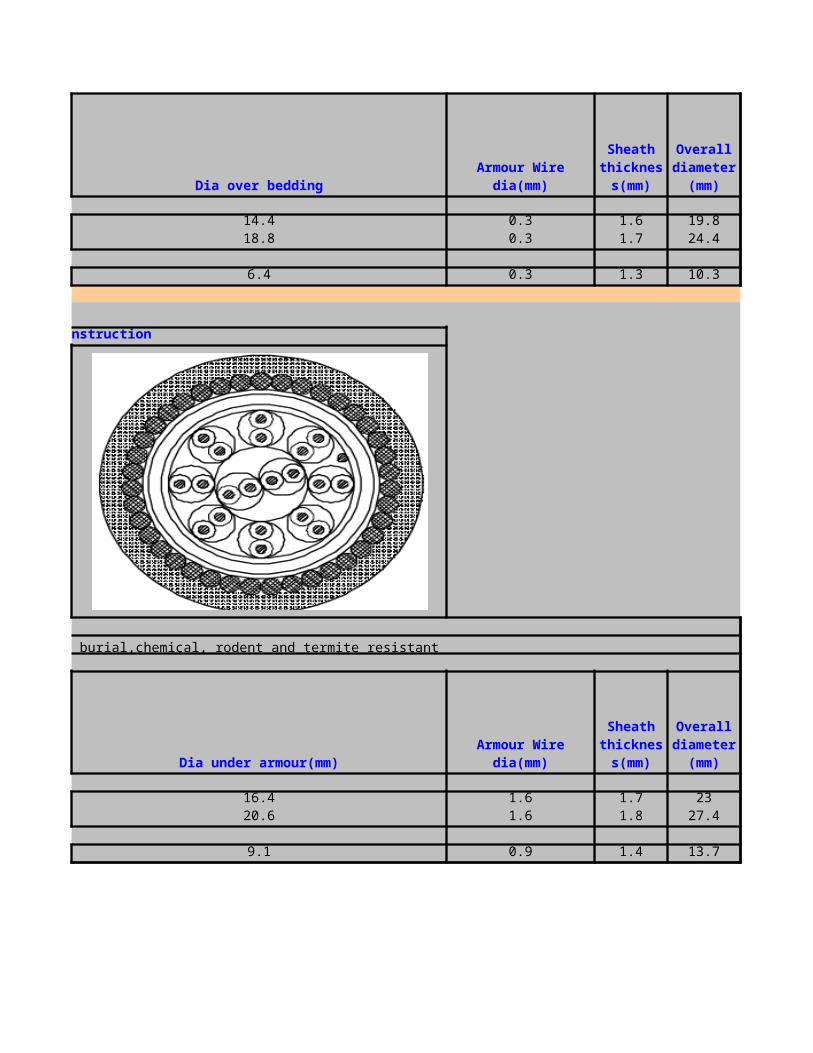
Number of fibres up to 36 up to 60Number of tubes 6 5
Fibre per tubes (max.) 6 12Tube diameter (mm) 2.1 2.8
Cable diameter, approx. (mm) 14.5 15.5Inner sheath thickness (mm) 1 1Outer sheath thickness (mm) 1.5 1.5Weight, approx. (kg per km) 160 185
Tested according to IEC 60794-1 IEC 60794-1
LF1A1VDE Code: A-DF2Y(ZN)2YNon-metallic aerial/underground cableApplications and features:Outdoor, non-metallic structure,Suitable for use in underground ducts and for aerial suspension,Suitable for span lengths up to 70 m,Longitudinally water blocked with gel,Loose tube, fully filled with thixotropic water-blocking gelPE inner sheath,black or red PE outer sheath
Mechanical Specifications
LF1A1Number of fibres up to 36 up to 72Number of tubes 6 6
Fibre per tube (max.) 6 12Cable diameter, approx. (mm) 12.5 15Inner sheath thickness (mm) 1 1Outer sheath thickness (mm) 1.5 1.5Weight, approx. (kg per km) 130 175
Tested according to IEC 60794-1 IEC 60794-1
LD1A1VDE Code: A-DQ2Y(ZN)2YNon-metallic aerial/underground cableApplications and features:Outdoor, non-metallic structure,Suitable for use in underground ducts and for aerial suspension,Suitable for span lengths up to 80 m,Longitudinally water blocked with swelling elements,Loose tube, fully filled with thixotropic water-blocking gelPE inner sheath,black or red PE outer sheath
Mechanical Specifications
LD1A1Number of fibres up to 36 up to 72Number of tubes 6 6
Fibre per tube (max.) 6 12Cable diameter, approx. (mm) 12.5 15Inner sheath thickness (mm) 1 1Outer sheath thickness (mm) 1.5 1.5
Tested according to IEC 60794-1 IEC 60794-1Weight, approx. (kg per km) 115 155
AD100VDE Code: A-DQ2Y2Y(T)Aerial outdoor fibre optic cableApplications and features:Aerial cable with integrated messenger,Suitable for span lengths up to 100 m,Longitudinally water blocked with swelling elements,Loose tube, fully filled with thixotropic water-blocking gelblack or red PE outer sheath
Mechanical Specifications

AD100Number of fibres up to 36 up to 60Number of tubes 6 5
Tube diameter (mm) 2.1 2.8Outer sheath thickness (mm) 1.5 1.5
Diameter over coated messenger (mm) 6 6Overall dimensions (mm) 10 / 18.5 11.5 / 20
Tested according to IEC 60794-1 IEC 60794-1Weight, approx. (kg per km) 145 160

FIBER OPTIC CABLE
Applications and features:Safety cable for indoor and outdoor use in tunnels, undergrounds or other applications where functional integrity under fire conditions is a must. Can be used in ducts or on cable trays
72 96 1206 10 12
2.8 2.8 2.813 16 181.5 1.5 1.5150 190 235
IEC 60794-1 IEC 60794-1 IEC 60794-1IEC 60332-1 & 60332-3-24 IEC 60332-1 & 60332-3-24 IEC 60332-1 & 60332-3-24
IEC 60754-2 IEC 60754-2 IEC 60754-2 IEC 61034-1/2 IEC 61034-1/2 IEC 61034-1/2
Applications and features:Outdoor, non-metallic structure,Suitable for duct installation by pulling or blowing

72 84 966 7 8
2.8 2.8 2.812 13 141.5 1.5 1.5125 145 160
IEC 60794-1 IEC 60794-1 IEC 60794-1
Applications and features:Outdoor, non-metallic structure,Suitable for duct installation by pulling or blowing,Longitudinally water blocked with swelling elements,Loose tube, fully filled with thixotropic water-blocking gel
72 84 966 7 8
2.8 2.8 2.812 13 141.5 1.5 1.5110 120 140
IEC 60794-1 IEC 60794-1 IEC 60794-1
Applications and features:Outdoor, non-metallic structure,Suitable for duct installation by pulling or blowing,Longitudinally water blocked with gel,Loose tube, fully filled with thixotropic water-blocking gel
72 96 1206 8 10
12 12 122.8 2.8 2.813 14.5 171.5 1.5 1.5135 175 225
IEC 60794-1 IEC 60794-1 IEC 60794-1
Applications and features:- Outdoor, non-metallic structure,Suitable for duct installation by pulling or blowing,Longitudinally water blocked with swelling elements,Loose tube, fully filled with thixotropic water-blocking gel
72 96 1206 8 10
12 12 122.8 2.8 2.813 14.5 161.5 1.5 1.5120 150 195
IEC 60794-1 IEC 60794-1 IEC 60794-1
Applications and features:Outdoor, non-metallic structure,Rodent resistant,High pulling force,Suitable for duct installation by pulling or blowing,Longitudinally water blocked with gel,Loose tube, fully filled with thixotropic water-blocking gel
72 96 1206 8 10
12 12 122.8 2.8 2.814 16 181.5 1.5 1.5165 205 255
IEC 60794-1 IEC 60794-1 IEC 60794-1
Applications and features:Outdoor, non-metallic structure,Rodent resistant,High pulling force,Suitable for duct installation by pulling or blowing,Longitudinally water blocked with swelling elements,Loose tube, fully filled with thixotropic water-blocking gel
72 96 1206 8 10
12 12 122.8 2.8 2.814 15.5 17.51.5 1.5 1.5145 185 230
IEC 60794-1 IEC 60794-1 IEC 60794-1
Applications and features:Outdoor structure, with aluminium moisture barrier,Suitable for duct installation by pulling or blowing,Longitudinally water blocked with gel,Loose tube, fully filled with thixotropic water-blocking gel

72 96 1206 8 10
12 12 122.8 2.8 2.813 15 171.5 1.5 1.5160 210 260
IEC 60794-1 IEC 60794-1 IEC 60794-1
Applications and features:Outdoor cable with corrugated steel tape armour for direct burial and rodent protection,Longitudinally water blocked,Central loose tube, fully filled with thixotropic water-blocking gel
Applications and features:Outdoor cable with corrugated steel tape armour for direct burial and rodent protection,Longitudinally water blocked,Central loose tube, fully filled with thixotropic water-blocking gel
Applications and features:Outdoor cable with corrugated steel tape armour for direct burial and rodent protection
72 96 120
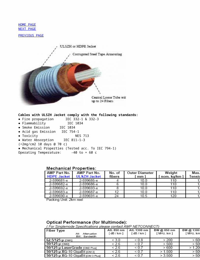
6 8 102.8 2.8 2.8
14.5 16.5 181 1 1
1.5 1.5 1.5175 220 270
IEC 60794-1 IEC 60794-1 IEC 60794-1
Applications and features:Outdoor cable with corrugated steel tape armour for direct burial and rodent protection
72 96 1206 8 10
2.8 2.8 2.814.5 16.5 181.5 1.5 1.5160 195 240
IEC 60794-1 IEC 60794-1 IEC 60794-1
Applications and features:Outdoor cable with corrugated steel tape armour for direct burial and rodent protection
72 96 1206 8 10
12 12 122.8 2.8 2.8
16.5 18.5 201 1 1
1.5 1.5 1.5220 270 325
IEC 60794-1 IEC 60794-1 IEC 60794-1
Applications and features:Outdoor cable with corrugated steel tape armour for direct burial and rodent protection
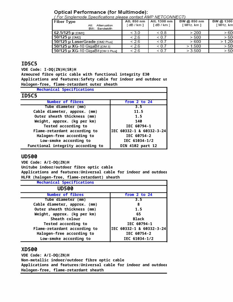
72 96 1206 8 10
12 12 122.8 2.8 2.8
16.5 18.5 201 1 1
1.5 1.5 1.5205 250 305
IEC 60794-1 IEC 60794-1 IEC 60794-1
Applications and features:Outdoor, non-metallic structure,Suitable for use in underground ducts and for aerial suspension,Suitable for span lengths up to 70 m,Longitudinally water blocked with gel,Loose tube, fully filled with thixotropic water-blocking gel
84 96 1207 8 10
12 12 1216 16.5 18.51 1 1
1.5 1.5 1.5185 220 270
IEC 60794-1 IEC 60794-1 IEC 60794-1
Applications and features:Outdoor, non-metallic structure,Suitable for use in underground ducts and for aerial suspension,Suitable for span lengths up to 80 m,Longitudinally water blocked with swelling elements,Loose tube, fully filled with thixotropic water-blocking gel
84 96 1207 8 10
12 12 1216 16.5 18.51 1 1
1.5 1.5 1.5IEC 60794-1 IEC 60794-1 IEC 60794-1
165 195 240
Applications and features:Aerial cable with integrated messenger,Suitable for span lengths up to 100 m,Longitudinally water blocked with swelling elements,Loose tube, fully filled with thixotropic water-blocking gel

72 or 9683
1.56
16 / 24.5IEC 60794-1
220
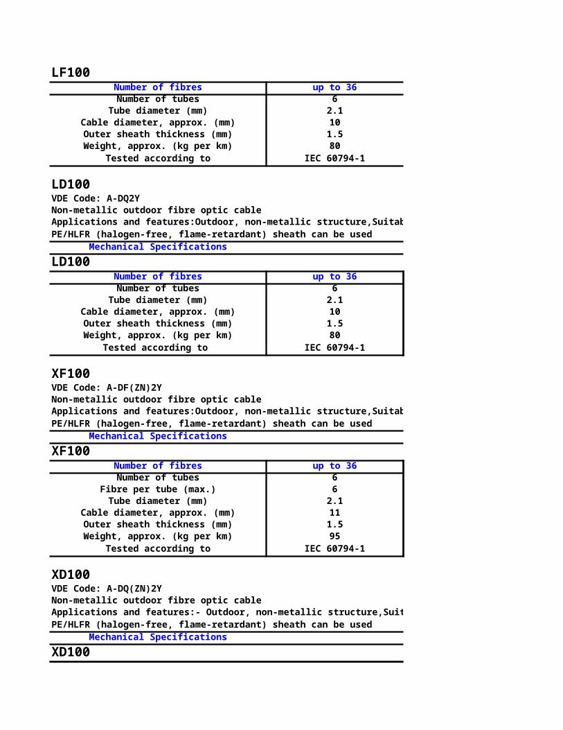
Applications and features:Safety cable for indoor and outdoor use in tunnels, undergrounds or other applications where functional integrity under fire conditions is a must. Can be used in ducts or on cable trays

144162.8201.5285
IEC 60794-1IEC 60332-1 & 60332-3-24
IEC 60754-2 IEC 61034-1/2

120 14410 122.8 2.816 181.5 1.5210 260
IEC 60794-1 IEC 60794-1
Applications and features:Outdoor, non-metallic structure,Suitable for duct installation by pulling or blowing,Longitudinally water blocked with swelling elements,Loose tube, fully filled with thixotropic water-blocking gel
120 14410 122.8 2.816 181.5 1.5180 220
IEC 60794-1 IEC 60794-1
Applications and features:Outdoor, non-metallic structure,Suitable for duct installation by pulling or blowing,Longitudinally water blocked with gel,Loose tube, fully filled with thixotropic water-blocking gel
14412122.8181.5270
IEC 60794-1
Applications and features:- Outdoor, non-metallic structure,Suitable for duct installation by pulling or blowing,Longitudinally water blocked with swelling elements,Loose tube, fully filled with thixotropic water-blocking gel
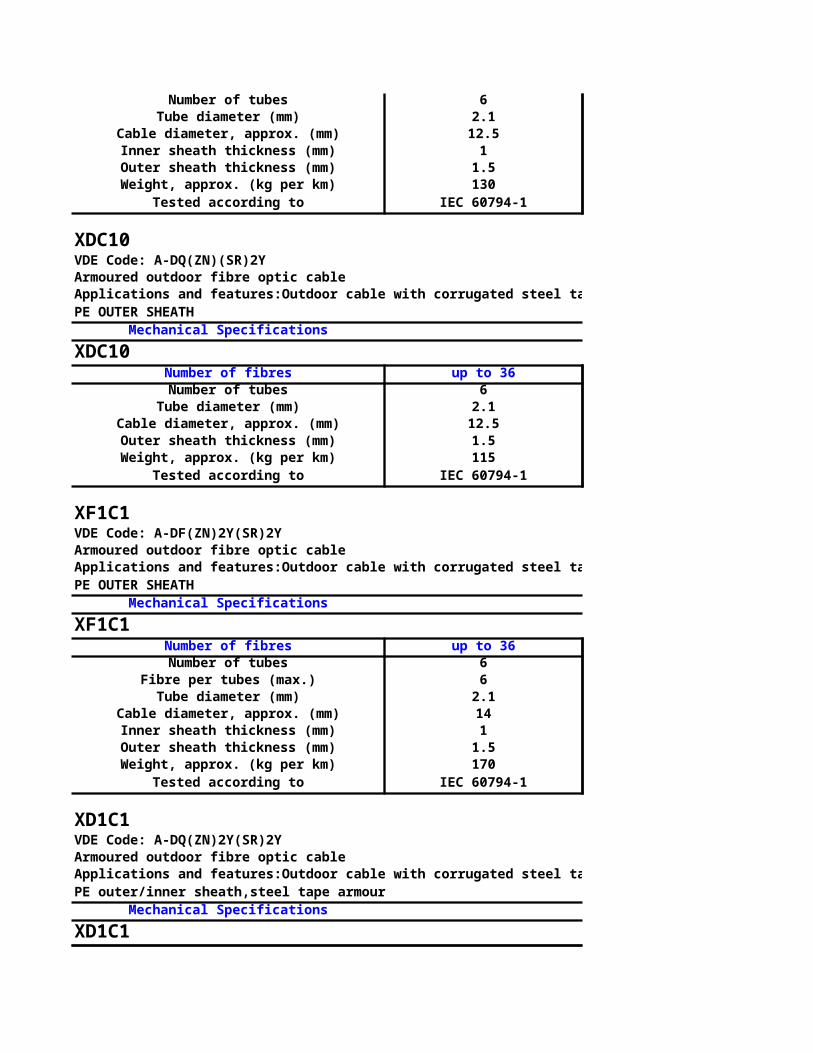
14412122.8181.5240
IEC 60794-1
Applications and features:Outdoor, non-metallic structure,Rodent resistant,High pulling force,Suitable for duct installation by pulling or blowing,Longitudinally water blocked with gel,Loose tube, fully filled with thixotropic water-blocking gel
14412122.8201.5310
IEC 60794-1
Applications and features:Outdoor, non-metallic structure,Rodent resistant,High pulling force,Suitable for duct installation by pulling or blowing,Longitudinally water blocked with swelling elements,Loose tube, fully filled with thixotropic water-blocking gel
14412122.8
19.51.5280
IEC 60794-1
Applications and features:Outdoor structure, with aluminium moisture barrier,Suitable for duct installation by pulling or blowing,Longitudinally water blocked with gel,Loose tube, fully filled with thixotropic water-blocking gel

14412122.8191.5310
IEC 60794-1
Applications and features:Outdoor cable with corrugated steel tape armour for direct burial and rodent protection,Longitudinally water blocked,Central loose tube, fully filled with thixotropic water-blocking gel
Applications and features:Outdoor cable with corrugated steel tape armour for direct burial and rodent protection,Longitudinally water blocked,Central loose tube, fully filled with thixotropic water-blocking gel
144

122.8201
1.5330
IEC 60794-1
144122.8201.5290
IEC 60794-1
14412122.8221
1.5385
IEC 60794-1

14412122.8221
1.5360
IEC 60794-1
Applications and features:Outdoor, non-metallic structure,Suitable for use in underground ducts and for aerial suspension,Suitable for span lengths up to 70 m,Longitudinally water blocked with gel,Loose tube, fully filled with thixotropic water-blocking gel
1441212
20.51
1.5320
IEC 60794-1
Applications and features:Outdoor, non-metallic structure,Suitable for use in underground ducts and for aerial suspension,Suitable for span lengths up to 80 m,Longitudinally water blocked with swelling elements,Loose tube, fully filled with thixotropic water-blocking gel
1441212
20.51
1.5IEC 60794-1
290
Applications and features:Aerial cable with integrated messenger,Suitable for span lengths up to 100 m,Longitudinally water blocked with swelling elements,Loose tube, fully filled with thixotropic water-blocking gel
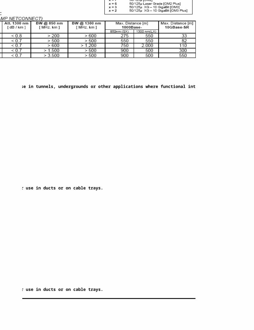
LOW VOLTAGE CABLES AND WIRES UPTO AND INCLUDING 600/1000 V
COPPER OR ALUMINIUM CONDUCTOR
PVC OR XLPE INSULATED CABLES
WITH OR WITHOUT PVC OUTER SHEATH
A. SINGLE CORE CABLES/WIRES
CURRENT CARRYING CAPACITY IN AMPERES
In Air
PVC Insulated XLPE Insulated
Copper Aluminium Copper
1.5 21 - - - 23
2.5 28 - - - 31
4 38 - - - 41
6 48 - - - 52
10 66 - - - 71
16 88 - 68 - 95
25 117 - 91 - 127
35 144 - 112 - 156
50 175 186 136 146 190
95 276 284 215 224 301
120 322 327 250 258 352
150 370 368 287 292 405
70 222 232 173 184 242
185 428 416 333 333 470
240 513 483 400 390 565
300 592 541 461 440 653
400 696 595 546 497 769
500 813 659 641 561 901
630 955 726 778 642 1080
800 1125 773 911 696 1247
1000 1286 834 1051 760 1428
*** l.a.1 l.a.1 l.a.1 l.a.1 l.a.1
LOW VOLTAGE CABLES 600/1000 V
HOME PAGE
NEXT PAGE
PREVIOUS PAGE
Nominal Area of Conductor
SqmmUnarmoure
d Armoure
dUnarmoure
dArmour
edUnarmour
ed
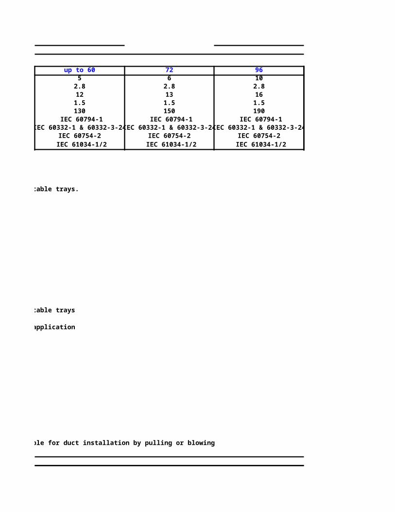
COPPER OR ALUMINIUM CONDUCTOR
PVC OR XLPE INSULATED CABLES
B. TWO CORE ARMOURED CABLES
CURRENT CARRYING CAPACITY IN AMPERES
In Air In Ground
PVC Insulated XLPE Insulated PVC Insulated
Copper Copper Copper
1.5 20 - 21 - 29
2.5 27 - 28 - 38
4 35 - 37 - 49
6 45 - 47 - 61
10 62 - 63 - 81
16 81 59 84 65 104
25 108 78 113 87 133
35 130 95 137 106 160
50 154 114 165 128 188
70 194 143 206 161 230
95 238 175 254 198 275
120 273 201 293 228 312
150 309 228 332 259 348
185 353 262 380 298 392
240 414 308 447 351 451
300 468 348 506 399 503
400 539 405 578 462 566
*** l.b.1 l.b.1 l.b.1 l.b.1 ll.b.1
LOW VOLTAGE CABLES 600/1000 V
COPPER OR ALUMINIUM CONDUCTOR
PVC OR XLPE INSULATED CABLES
C. THREE OR FOUR CORE ARMOURED CABLES
CURRENT CARRYING CAPACITY IN AMPERES
In Air In Ground
PVC Insulated XLPE Insulated PVC Insulated
Copper Copper Copper
1.5 15 - 17 - 25
Nominal Area of Conductor
Sqmm Aluminium
Aluminium
Nominal Area of Conductor
Sqmm Aluminium
Aluminium

2.5 21 - 23 - 32
4 28 - 30 - 42
6 35 - 38 - 53
10 48 - 52 - 70
16 65 50 70 54 92
25 84 66 91 71 114
35 105 81 113 88 138
50 129 100 140 108 165
70 161 125 175 136 201
95 199 155 218 169 243
120 231 180 254 198 277
150 261 204 288 225 307
185 301 235 333 260 348
240 357 279 396 310 403
300 406 319 449 353 452
400 471 375 519 414 512
500 530 426 590 470 551
*** l.b.1 l.b.1 l.b.1 l.b.1 ll.b.1
MEDIUM VOLTAGE CABLES 3.8/6.6 KV TO 19/33 KV
COPPER OR ALUMINIUM CONDUCTOR
XLPE INSULATED CABLES
A. SINGLE CORE CABLES
CURRENT CARRYING CAPACITY IN AMPERES
In Air In Ground
Sqmm Copper Aluminium Copper
Trefoil Flat Trefoil Flat Trefoil
35 152 170 117 132 154
50 182 203 140 158 182
70 227 254 175 198 222
95 274 313 211 240 264
120 318 360 244 278 300
150 360 410 278 316 335
185 410 470 330 365 376
240 481 560 380 435 428
Nominal Area of Conductor
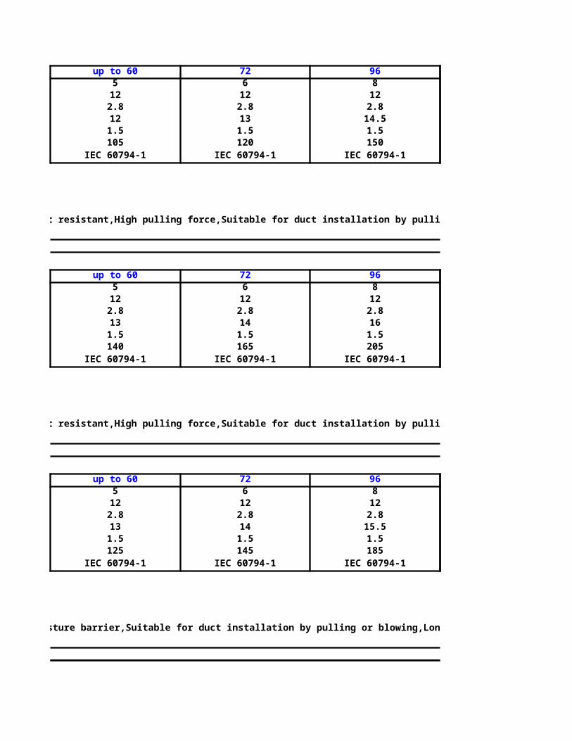
300 545 640 430 498 472
400 625 750 500 585 517
500 700 873 570 685 553
630 784 1035 655 810 605
*** l.a.2 l.a.3 l.a.2 l.a.3 ll.a.2
CURRENT CARRYING CAPACITY IN AMPERES
In Air In Ground
Copper Copper
35 130 100 145 110
50 160 120 170 130
70 196 151 210 160
95 240 184 250 193
120 275 214 284 220
150 312 240 318 246
185 355 277 360 279
240 415 326 410 323
300 469 370 458 362
400 530 427 510 411
*** l.b.1 l.b.1 ll.b.1 ll.b.1
B. THREE CORE CABLES
Nominal Area of Conductor
SqmmAluminiu
mAlumini
um

LOW VOLTAGE CABLES AND WIRES UPTO AND INCLUDING 600/1000 V
COPPER OR ALUMINIUM CONDUCTOR
PVC OR XLPE INSULATED CABLES
WITH OR WITHOUT PVC OUTER SHEATH
A. SINGLE CORE CABLES/WIRES
CURRENT CARRYING CAPACITY IN AMPERES
In Air In Ground
XLPE Insulated PVC Insulated XLPE Insulated
Copper Aluminium Copper Copper
Armoured
- - - 32 - 34 -
- - - 42 - 45 -
- - - 55 - 58 -
- - - 69 - 73 -
- - - 91 - 97 -
- 73 - 118 92 125 97
- 98 - 152 118 161 125
- 121 - 183 142 194 150
206 147 160 215 167 229 178
313 234 246 312 245 330 259
359 273 284 350 276 371 293
405 314 320 387 307 410 324
256 189 202 262 206 287 218
459 366 367 430 344 455 364
533 440 430 486 392 515 416
597 508 485 533 435 565 461
656 603 549 568 476 601 505
727 710 619 614 525 651 555
809 861 707 660 578 697 610
850 1008 765 675 608 712 641
914 1165 834 707 648 744 682
l.a.1 l.a.1 l.a.1 ll.a.1 ll.a.1 ll.a.1 ll.a.1
LOW VOLTAGE CABLES 600/1000 V
Aluminium
Aluminium
Armoured
Unarmoured
Armoured
Unarmoured
Armoured
Unarmoured

COPPER OR ALUMINIUM CONDUCTOR
PVC OR XLPE INSULATED CABLES
B. TWO CORE ARMOURED CABLES
CURRENT CARRYING CAPACITY IN AMPERES
In Ground In Duct
PVC Insulated XLPE Insulated PVC Insulated XLPE Insulated
Copper Copper Copper
- 32 - 24 - 26 -
- 41 - 32 - 34 -
- 53 - 41 - 44 -
- 66 - 51 - 54 -
- 87 - 67 - 72 -
81 113 88 87 67 93 72
104 146 113 112 87 120 93
124 174 135 135 105 145 112
146 205 159 160 124 172 133
179 251 196 196 153 211 164
214 301 234 237 184 255 198
243 341 266 269 210 290 226
271 381 297 301 235 325 253
307 428 335 340 266 367 288
355 494 388 392 309 424 334
397 552 435 438 346 475 375
454 619 495 493 402 533 434
ll.b.1 ll.b.1 ll.b.1 lll.1 lll.1 lll.1 lll.1
LOW VOLTAGE CABLES 600/1000 V
COPPER OR ALUMINIUM CONDUCTOR
PVC OR XLPE INSULATED CABLES
C. THREE OR FOUR CORE ARMOURED CABLES
CURRENT CARRYING CAPACITY IN AMPERES
In Ground In Duct
PVC Insulated XLPE Insulated PVC Insulated XLPE Insulated
Copper Copper Copper
- 27 - 20 - 22 -
Aluminium
Aluminium
Aluminium
Aluminium
Aluminium
Aluminium
Aluminium
Aluminium

- 35 - 27 - 28 -
- 45 - 35 - 37 -
- 57 - 43 - 46 -
- 75 - 58 - 61 -
71 98 76 75 58 79 61
89 122 95 96 74 101 79
107 148 114 116 90 122 95
128 176 137 138 107 146 113
156 215 167 169 131 179 139
188 258 200 204 159 216 168
216 295 229 233 182 247 192
240 328 255 261 203 276 215
272 371 290 295 231 313 244
316 430 338 334 269 363 285
355 481 378 384 303 407 320
408 545 433 443 347 469 373
449 595 485 485 385 514 415
ll.b.1 ll.b.1 ll.b.1 lll.1 lll.1 lll.1 lll.1
MEDIUM VOLTAGE CABLES 3.8/6.6 KV TO 19/33 KV
CURRENT CARRYING CAPACITY IN AMPERES
In Ground
Copper Aluminium
Flat Trefoil Flat
160 119 124
189 141 146
231 172 179
275 204 212
314 232 242
352 261 272
399 294 309
464 339 360

525 379 407
600 427 468
684 465 537
772 516 615
ll.a.3 ll.a.2 ll.a.3
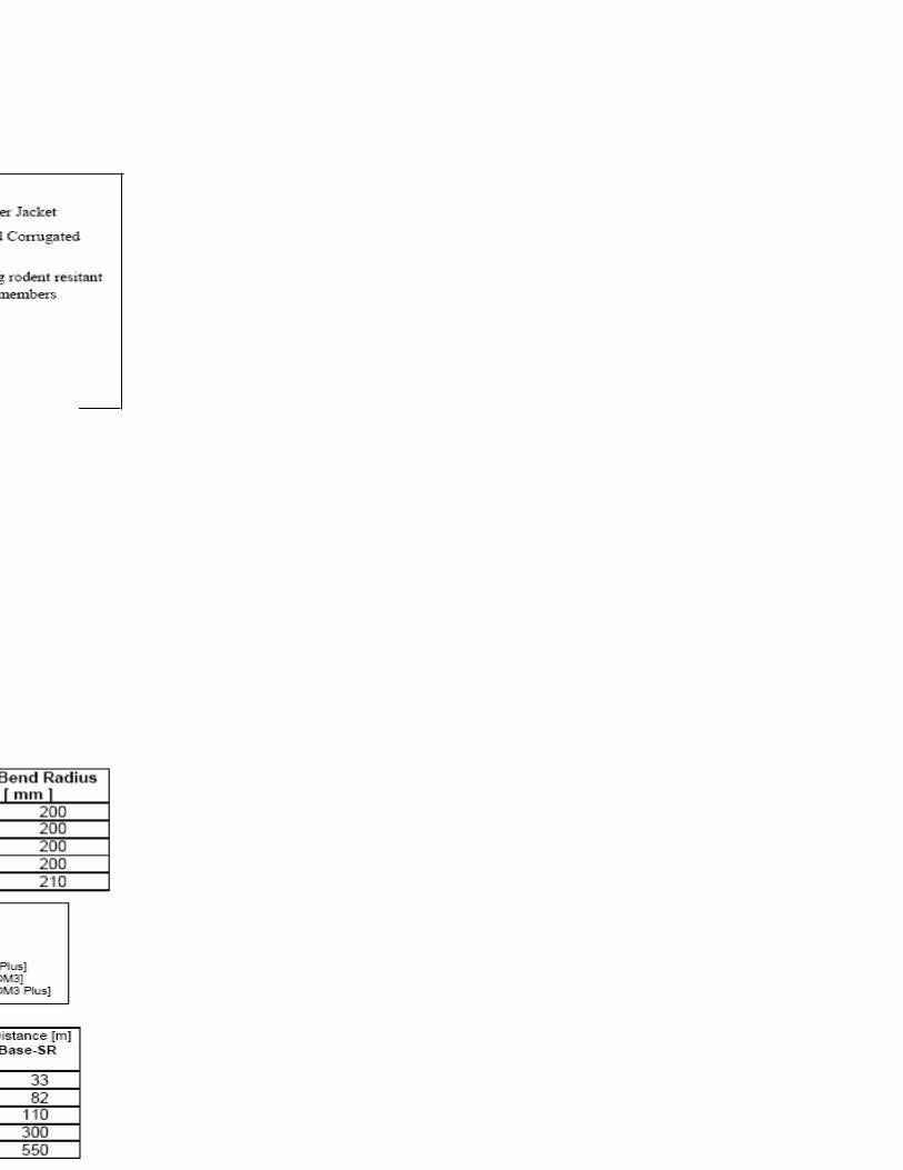
Thermal Resistivity of Soil in °C m/w
0.7 0.8 0.9 1
1.5/2.5 1.12 1.09 1.07 1.04
4 1.13 1.1 1.07 1.05
6 1.14 1.1 1.07 1.05
10 1.15 1.11 1.08 1.05
16 1.16 1.12 1.08 1.05
25 1.17 1.13 1.09 1.05
35 1.17 1.13 1.09 1.06
50 1.17 1.13 1.09 1.06
70 1.18 1.14 1.09 1.06
95 1.18 1.14 1.09 1.06
120 1.19 1.14 1.1 1.06
150 1.19 1.14 1.1 1.06
185 1.19 1.14 1.1 1.06
240 1.2 1.15 1.1 1.07
300/400 1.2 1.15 1.1 1.07
RATING FACTORS FOR VARIATION IN THERMAL RESISTIVITY OF SOIL
FOR TWO OR THREE SINGLE-CORE CABLES LAID DIRECT IN THE GROUND
Thermal Resistivity of Soil in °C m/w
0.7 0.8 0.9 1
50 1.21 1.16 1.11 1.07
70 1.22 1.16 1.12 1.07
95 1.22 1.16 1.12 1.07
120 1.22 1.16 1.12 1.07
150 1.22 1.16 1.12 1.07
185 1.22 1.17 1.12 1.07
240 1.23 1.17 1.12 1.07
HOME PAGERATING FACTORS FOR VARIATION IN
THERMAL RESISTIVITY OF SOIL
NEXT PAGETWIN OR MULTI-CORE CABLES LAID
DIRECT IN THE GROUND
PREVIOUS PAGE
Nominal Area of Conductor
Sqmm
Nominal Area of Conductor
Sqmm
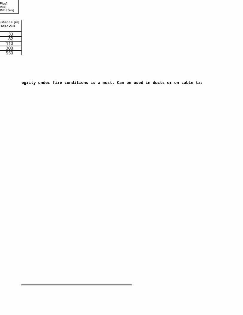
300 1.23 1.17 1.12 1.07
400 1.23 1.17 1.12 1.07
500 1.23 1.17 1.12 1.07
630 1.23 1.17 1.12 1.07
800 1.23 1.17 1.12 1.07
1000 1.24 1.18 1.12 1.07
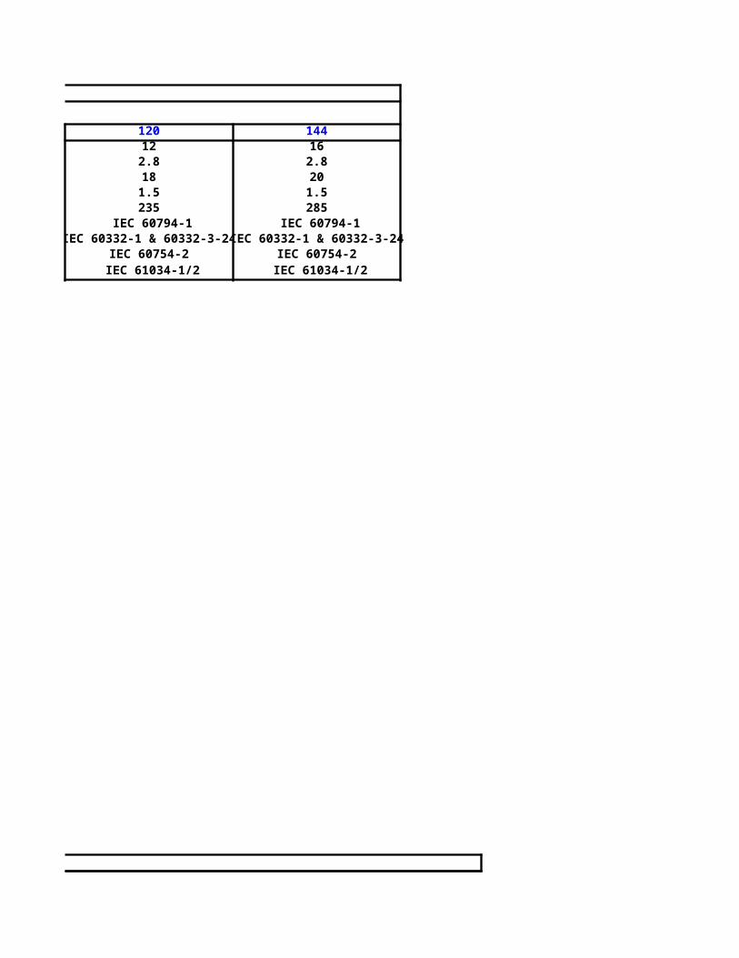
Thermal Resistivity of Soil in °C m/w
1.2 1.5 2 2.5 3 3.5 4
1 0.94 0.86 0.8 0.75 0.7 0.66
1 0.94 0.85 0.79 0.74 0.69 0.65
1 0.93 0.85 0.79 0.74 0.68 0.64
1 0.93 0.85 0.78 0.73 0.67 0.63
1 0.93 0.84 0.77 0.72 0.66 0.62
1 0.93 0.83 0.77 0.71 0.65 0.61
1 0.92 0.83 0.76 0.71 0.65 0.61
1 0.92 0.83 0.76 0.71 0.65 0.61
1 0.92 0.83 0.75 0.7 0.64 0.6
1 0.92 0.83 0.75 0.7 0.64 0.6
1 0.92 0.82 0.75 0.69 0.63 0.6
1 0.92 0.82 0.75 0.69 0.63 0.59
1 0.92 0.82 0.74 0.69 0.63 0.59
1 0.92 0.81 0.74 0.69 0.63 0.59
1 0.92 0.81 0.74 0.69 0.63 0.59
RATING FACTORS FOR VARIATION IN THERMAL RESISTIVITY OF SOIL
FOR TWO OR THREE SINGLE-CORE CABLES LAID DIRECT IN THE GROUND
Thermal Resistivity of Soil in °C m/w
1.2 1.5 2 2.5 3 3.5 4
1 0.91 0.81 0.73 0.68 0.63 0.59
1 0.91 0.81 0.73 0.68 0.63 0.59
1 0.91 0.81 0.73 0.68 0.63 0.59
1 0.91 0.81 0.73 0.68 0.63 0.59
1 0.91 0.81 0.73 0.68 0.63 0.59
1 0.91 0.81 0.73 0.68 0.62 0.59
1 0.91 0.8 0.73 0.68 0.62 0.59
RATING FACTORS FOR VARIATION IN THERMAL RESISTIVITY OF SOILTWIN OR MULTI-CORE CABLES LAID
DIRECT IN THE GROUND

1 0.91 0.8 0.73 0.68 0.62 0.59
1 0.91 0.8 0.73 0.67 0.62 0.58
1 0.91 0.8 0.73 0.67 0.62 0.58
1 0.91 0.8 0.73 0.67 0.61 0.58
1 0.91 0.8 0.72 0.66 0.61 0.58
1 0.91 0.8 0.72 0.66 0.61 0.58
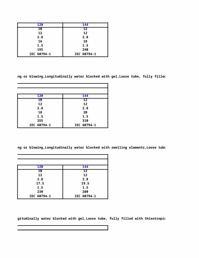
Sq. mm
1.5 26.3 26.3 - -
2.5 16.1 16.1 - -
4 10 10 - -
6 6.7 6.7 - -
10 4 4 - -
16 2.5 2.5 4.8 4.8
25 1.55 1.6 3.1 3.1
35 1.13 1.16 2.2 2.2
50 0.84 0.87 1.4 1.5
70 0.6 0.65 0.96 0.98
95 0.45 0.52 0.7 0.76
120 0.37 0.45 0.57 0.64
150 0.31 0.41 0.47 0.55
185 0.26 0.38 0.38 0.48
240 0.23 0.35 0.31 0.42
300 0.2 0.33 0.26 0.38
400 0.19 0.32 0.25 0.37
500 0.18 0.31 0.25 0.36
630 0.16 0.31 0.24 0.36
800 0.16 0.3 0.24 0.35
1000 0.15 0.29 0.23 0.35
HOME PAGE
NEXT PAGE
PREVIOUS PAGE
Nominal Area of Conduct
or
3 or 4 Single Core Cables
Copper Trefoil
Copper Flat
Spaced*
Aluminium Trefoil
Aluminium Flat Spaced*
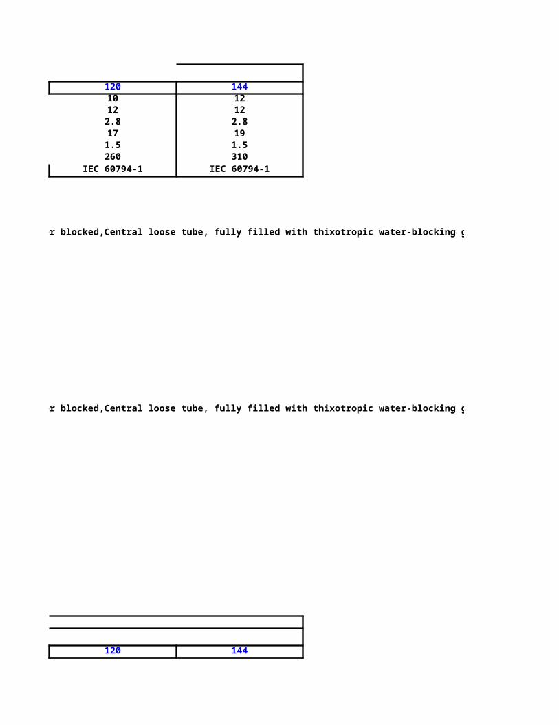
3 or 4 Single Core Cables
Sq. mm
1.5 26.7 26.7 - -
2.5 16.4 16.4 - -
4 10.2 10.2 - -
6 6.8 6.8 - -
10 4 4 - -
16 2.5 2.5 4.2 4.2
25 1.65 1.65 2.7 2.7
35 1.15 1.15 1.95 1.95
50 0.87 0.9 1.4 1.4
70 0.62 0.7 0.98 1.05
95 0.47 0.58 0.74 0.83
120 0.39 0.51 0.6 0.7
150 0.33 0.45 0.49 0.6
185 0.28 0.41 0.41 0.53
240 0.24 0.37 0.34 0.46
300 0.21 0.34 0.29 0.41
400 0.2 0.33 0.25 0.36
500 0.18 0.31 - -
630 0.17 0.29 - -
800 0.16 0.28 - -
1000 0.16 0.27 - -
Nominal Area of Conduct
or
Copper Trefoil
Copper Flat
spaced*
Aluminium Trefoil
Aluminium Flat spaced*

VOLTAGE DROP
600/1000 V TYPE-5 PVC INSULATED CABLES
VOLTAGE DROPS AT MAXIMUM
Copper Copper
30.4 - 26.3 -
18.6 - 16.1 -
11.6 - 10 -
7.7 - 6.7 -
4.6 - 4 -
2.9 4.8 2.5 4.8
1.8 3.1 1.6 3.1
1.3 2.2 1.2 2.2
0.98 1.7 0.85 1.7
0.69 1.2 0.6 1.2
0.51 0.89 0.44 0.89
0.41 0.74 0.36 0.74
0.35 0.64 0.3 0.64
0.29 0.56 0.25 0.56
0.24 0.48 0.21 0.48
0.21 0.44 0.18 0.44
0.19 0.41 0.16 0.41
0.17 0.39 0.15 0.39
0.16 0.37 - -
0.15 0.36 - -
0.15 0.35 - -
VOLTAGE DROP
600/1000 V XLPE INSULATED CABLES
VOLTAGE DROPS AT MAXIMUM
CONDUCTOR OPERATING TEMPERATURE IN V/A/KM
2 Core or 2 Single Core Cables- Touching3 and 4 Core
Cables
Aluminium
Aluminium
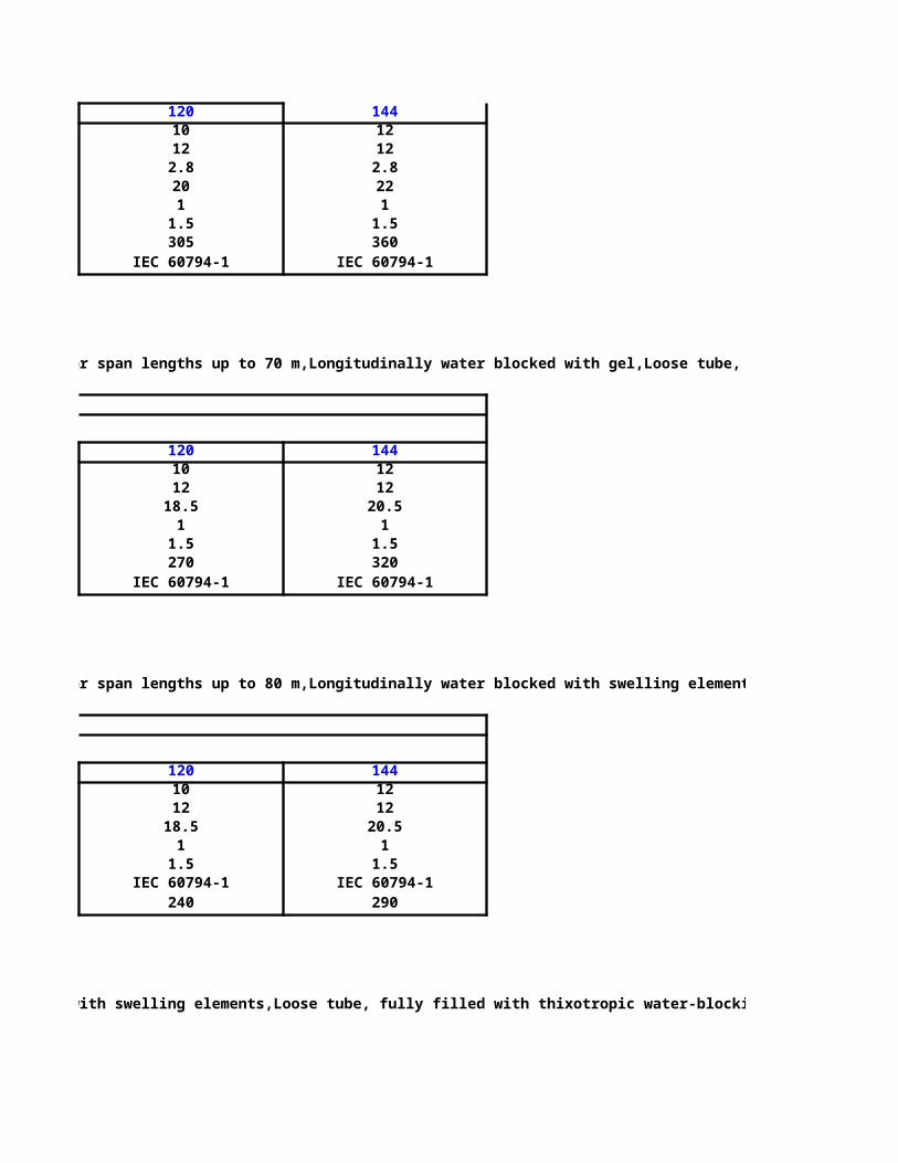
CONDUCTOR OPERATING TEMPERATURE IN V/A/KM
2 Core or 2 Single Core Cables - Touching
Copper Copper
30.9 - 26.7 -
18.9 - 16.4 -
11.8 - 10.2 -
7.9 - 6.8 -
4.7 - 4 -
2.9 4.8 2.5 4.2
1.9 3.1 1.65 2.7
1.35 2.2 1.15 1.95
1 1.65 0.87 1.45
0.69 1.15 0.6 0.97
0.52 0.84 0.45 0.72
0.42 0.72 0.37 0.58
0.35 0.61 0.3 0.47
0.29 0.52 0.26 0.39
0.24 0.44 0.21 0.31
0.21 0.39 0.19 0.26
0.2 0.36 0.17 0.21
0.17 0.34 - -
0.16 0.32 - -
0.15 0.31 - -
0.15 0.29 - -
3 and 4 Core Cables
Aluminium
Aluminum

Fire Resistant Tests
Stringent tests – including IEC 60331, BS 6387 and SS 299 – are performed to ensure that such cables are fire-resistant.
Resistance to fire alone (IEC 60331, BS 6387, SS 299)
Category C - Cables are subjected to fire at 950°C for 3 hours
Category B - Cables are subjected to fire at 750°C for 3 hours
Category A - Cables are subjected to fire at 650°C for 3 hours
* In accordance to IEC 60331, cables are subjected to fire at 750°C for 3 hours. In not less than twelve hours after the test, the cable
again be energized, and there shall not be any breakdown.
Resistance to fire with water (BS 6387, SS 299)
Category W - Cables are subjected to fire at 650°C for 15 minutes, then at 650°C with water spray for a further 15 minutes.
Resistance to fire with mechanical shock (BS 6387, SS 299)
Category X - Cables are subjected to fire at 650°C with mechanical shock for 15 minutes.
Category Y - Cables are subjected to fire at 750°C with mechanical shock for 15 minutes.
Category Z - Cables are subjected to fire at 950°C with mechanical shock for 15 minutes.
During the test, the flame and test voltage shall be applied continuously for a period of 3 hours and no fuse shall be ruptured nor a
lamp extinguished.
Flame Propagation Tests
Part 1 : Tests on a single vertical insulated wire or cable
Part 3 : Tests on bunched wires and cables under fire condition.
The IEC 60332-3 specification creates a realistic fire situation, and specifies methods for assessing the flame retardance of bunched
varying densities of combustible material.
This technical report gives details of a test where a number of cables are bunched together to form various test sample installation
3 test categories to test different amount of combustible material contained in a bundle of cable.
IEC 60332-3-22 - The number of test pieces required to provide a total volume of 7 litres of non-metallic material shall be bunched
(Former IEC 332-3A) ladder exposed to flame for 40 minutes.
IEC 60332-3-23 - The number of test pieces required to provide a total volume of 3.5 litres of non-metallic material shall be bunche
(Former IEC 332-3B) ladder and exposed to flame for 40 minutes.
IEC 60332-3-24 - The number of test pieces required to provide a total volume of 1.5 litres of non-metallic material shall be bunche
(Former IEC 332-3C) ladder and exposed to flame for 20 minutes.
The cable specimens are placed vertically next to each other and then exposed to the flame for a specified duration. After the burn
HOME PAGE
NEXT PAGE
PREVIOUS PAGE

the charred or affected portion should not exceed a height of 2.5 meters.
Acid Gas Emission Tests
A fire can produce corrosive halogen gases, generated by burning PVC or chlorine containing material. HCI gas combines with the wa
eyes, mouth, throat, nose and lungs to form hydrochloric acid, which contributes to loss of co-ordination and orientation. This in tur
a feeling of panic and inability to exit the building, thus increasing potential fatalities by inhalation of carbon monoxide and oxygen
Additional dangers exist in a fire situation. Chlorine, bromine or fluorine, found in building materials, can combine with the conden
all metallic materials in the proximity of a fire thus resulting in high levels of corrosion which will damage computers and office ma
Structural ferrous metals can be so corroded that the building has to be demolished.
IEC 60754-2 specifies a method in determining the degree of acidity of gases evolved during the combustion of materials taken from
by measuring pH and conductivity. This standard requires the weighted pH value of not less than 4.3 when related to 1 litre of wate
weighted value of conductivity should not exceed 10μS/mm.
Smoke Emission TestsSmoke hinders fire-fighting efforts and prevents safe evacuation from the building. Smoke extraction equipment helps, but low smstop the problem before it starts. Conventional insulation and sheathing materials such as polyvinyl chloride (PVC) can produce larsmoke when burned, thus contributing to disorientation and smoke inhalation damage.
Measuring the density of smoke produced by burning cables is important as it is related to the evacuation of people and accessibility
The “3 meter cube test” (also known as IEC 61034) measures the amount of smoke created by cables in the event of a fire. A one-m
of cable is placed in a 3m2 enclosure, and exposed to a beam of light through a clear window. This light travels across the enclosure
connected to recording equipment in the window on the other end. A fire is then generated within the container and the minimum l
recorded. A minimum light transmission value greater than 60% is acceptable.
Limiting Oxygen IndexOxygen index (limiting oxygen index) is the most widely used fire parameter in the assessment of materials. The index is the miniof oxygen in an oxygen/nitrogen mixture in which the material will burn.
Air contains 21% oxygen and it is often stated that material with an oxygen index greater than 28% will be self-extinguishing. Low
Halogen Flame Retardant material used by Tai Sin is greater than 34%.
BS 6387, SS 299, *IEC 60331
Stringent tests – including IEC 60331, BS 6387 and SS 299 – are performed to ensure that such cables are fire-resistant.
Category C - Cables are subjected to fire at 950°C for 3 hours
Category B - Cables are subjected to fire at 750°C for 3 hours
Category A - Cables are subjected to fire at 650°C for 3 hours
* In accordance to IEC 60331, cables are subjected to fire at 750°C for 3 hours. In not less than twelve hours after the test, the cable
Category W - Cables are subjected to fire at 650°C for 15 minutes, then at 650°C with water spray for a further 15 minutes.
Category X - Cables are subjected to fire at 650°C with mechanical shock for 15 minutes.
Category Y - Cables are subjected to fire at 750°C with mechanical shock for 15 minutes.
Category Z - Cables are subjected to fire at 950°C with mechanical shock for 15 minutes.
During the test, the flame and test voltage shall be applied continuously for a period of 3 hours and no fuse shall be ruptured nor a
IEC 60332, BS 4066
Tests on electric cables under fire conditions.
Part 3 : Tests on bunched wires and cables under fire condition.
The IEC 60332-3 specification creates a realistic fire situation, and specifies methods for assessing the flame retardance of bunched
This technical report gives details of a test where a number of cables are bunched together to form various test sample installation
3 test categories to test different amount of combustible material contained in a bundle of cable.
IEC 60332-3-22 - The number of test pieces required to provide a total volume of 7 litres of non-metallic material shall be bunched
(Former IEC 332-3A) ladder exposed to flame for 40 minutes.
IEC 60332-3-23 - The number of test pieces required to provide a total volume of 3.5 litres of non-metallic material shall be bunche
(Former IEC 332-3B) ladder and exposed to flame for 40 minutes.
IEC 60332-3-24 - The number of test pieces required to provide a total volume of 1.5 litres of non-metallic material shall be bunche
(Former IEC 332-3C) ladder and exposed to flame for 20 minutes.
The cable specimens are placed vertically next to each other and then exposed to the flame for a specified duration. After the burn
Specification for performance requirements for cables required to maintain circuit integrity under fire conditions.

the charred or affected portion should not exceed a height of 2.5 meters.
IEC 60754, BS 6425
Test on gases evolved during combustion of electric cables.
A fire can produce corrosive halogen gases, generated by burning PVC or chlorine containing material. HCI gas combines with the wa
eyes, mouth, throat, nose and lungs to form hydrochloric acid, which contributes to loss of co-ordination and orientation. This in tur
a feeling of panic and inability to exit the building, thus increasing potential fatalities by inhalation of carbon monoxide and oxygen
Additional dangers exist in a fire situation. Chlorine, bromine or fluorine, found in building materials, can combine with the conden
all metallic materials in the proximity of a fire thus resulting in high levels of corrosion which will damage computers and office ma
Structural ferrous metals can be so corroded that the building has to be demolished.
IEC 60754-2 specifies a method in determining the degree of acidity of gases evolved during the combustion of materials taken from
by measuring pH and conductivity. This standard requires the weighted pH value of not less than 4.3 when related to 1 litre of wate
weighted value of conductivity should not exceed 10μS/mm.
IEC 61034, BS 7622
Smoke hinders fire-fighting efforts and prevents safe evacuation from the building. Smoke extraction equipment helps, but low smstop the problem before it starts. Conventional insulation and sheathing materials such as polyvinyl chloride (PVC) can produce larsmoke when burned, thus contributing to disorientation and smoke inhalation damage.
Measuring the density of smoke produced by burning cables is important as it is related to the evacuation of people and accessibility
The “3 meter cube test” (also known as IEC 61034) measures the amount of smoke created by cables in the event of a fire. A one-m
of cable is placed in a 3m2 enclosure, and exposed to a beam of light through a clear window. This light travels across the enclosure
connected to recording equipment in the window on the other end. A fire is then generated within the container and the minimum l
recorded. A minimum light transmission value greater than 60% is acceptable.
ASTM D 2863
Oxygen index (limiting oxygen index) is the most widely used fire parameter in the assessment of materials. The index is the miniof oxygen in an oxygen/nitrogen mixture in which the material will burn.
Air contains 21% oxygen and it is often stated that material with an oxygen index greater than 28% will be self-extinguishing. Low
Halogen Flame Retardant material used by Tai Sin is greater than 34%.
Measurement of smoke density of electric cables burning underdefined conditions.
Measuring the minimum oxygen concentration to supportcandle-like combustion of plastics.

A-02YSF(L)2Y Bd
10 X 4 X 0.4 - 1.4 14
20 X 4 X 0.4 - 1.4 16
50 X 4 X 0.4 - 1.4 23
100 X 4 X 0.4 1 1.6 30
150 X 4 X 0.4 2 1.8 36
200 X 4 X 0.4 2 1.8 40
300 X 4 X 0.4 3 2 49
400 X 4 X 0.4 4 2.2 56
500 X 4 X 0.4 5 2.2 61
10 X 4 X 0.6 - 1.4 17
20 X 4 X 0.6 - 1.4 20
50 X 4 X 0.6 - 1.6 29
100 X 4 X 0.6 1 1.8 39
150 X 4 X 0.6 2 2 47
200 X 4 X 0.6 2 2.2 53
300 X 4 X 0.6 3 2.4 64
400 X 4 X 0.6 4 2.4 73
500 X 4 X 0.6 5 2.4 81
A-02YSF2Y Bd
10 X 4 X 0.6 - 2.1 19
20 X 4 X 0.6 - 2.3 25
50 X 4 X 0.6 1 2.5 33
100 X 4 X 0.6 1 2.7 44
H07V-R
Geometrical Data
HOME PAGE
NEXT PAGE
PREVIOUS PAGE
Number of quads and conductor
diameter(mm)
Number of spare quads
Thickness of theouter
sheath(mm)Overall diameter
(mm)
Number of quads and conductor
diameter(mm)
Number of spare quads
Thickness of theouter
sheath(mm)Overall diameter
(mm)

Core colour
1 x 1.5 R1 BLACK 0.7
1 x 1.5 U1 BLACK 0.7
1 x 2.5 R1 BLACK 0.8
1 x 2.5 U1 BLACK 0.8
1 x 4 R1 BLACK 0.8
1 x 4 U1 BLACK 0.8
1 x 6 R1 BLACK 0.8
1 x 6 U1 BLACK 0.8
1 x 10 R1 BLACK 1
1 x 10 U1 BLACK 1
1 x 16 R1 BLACK 1
1 x 16 U1 BLACK 1
1 x 1.5 R1 RED 0.7
1 x 1.5 U1 RED 0.7
1 x 2.5 R1 RED 0.8
1 x 2.5 U1 RED 0.8
1 x 4 R1 RED 0.8
1 x 4 U1 RED 0.8
1 x 6 R1 RED 0.8
1 x 6 U1 RED 0.8
1 x 10 R1 RED 1
1 x 10 U1 RED 1
1 x 16 R1 RED 1
1 x 16 U1 RED 1
1 x 1.5 R1 BROWN 0.7
1 x 1.5 U1 BROWN 0.7
1 x 2.5 R1 BROWN 0.8
1 x 2.5 U1 BROWN 0.8
1 x 4 R1 BROWN 0.8
1 x 4 U1 BROWN 0.8
1 x 6 R1 BROWN 0.8
1 x 6 U1 BROWN 0.8
1 x 10 R1 BROWN 1
1 x 10 U1 BROWN 1
1 x 16 R1 BROWN 1
1 x 16 U1 BROWN 1
SIZE(nom.) (n/mm²)
CENELECCODE H07V
Thickn.of insulation
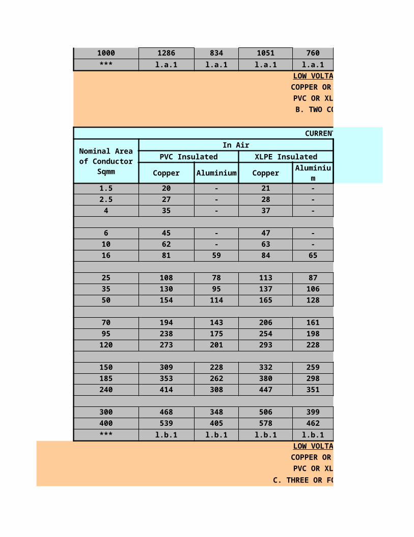
1 x 1.5 R1 BLUE 0.7
1 x 1.5 U1 BLUE 0.7
1 x 2.5 R1 BLUE 0.8
1 x 2.5 U1 BLUE 0.8
1 x 4 R1 BLUE 0.8
1 x 4 U1 BLUE 0.8
1 x 6 R1 BLUE 0.8
1 x 6 U1 BLUE 0.8
1 x 10 R1 BLUE 1
1 x 10 U1 BLUE 1
1 x 16 R1 BLUE 1
1 x 16 U1 BLUE 1
1 x 1.5 R1 WHITE 0.7
1 x 1.5 U1 WHITE 0.7
1 x 2.5 R1 WHITE 0.8
1 x 2.5 U1 WHITE 0.8
1 x 4 R1 WHITE 0.8
1 x 4 U1 WHITE 0.8
1 x 6 R1 WHITE 0.8
1 x 6 U1 WHITE 0.8
1 x 10 R1 WHITE 1
1 x 10 U1 WHITE 1
1 x 16 R1 WHITE 1
1 x 16 U1 WHITE 1
1 x 1.5 R1 GREY 0.7
1 x 1.5 U1 GREY 0.7
1 x 2.5 R1 GREY 0.8
1 x 2.5 U1 GREY 0.8
1 x 4 R1 GREY 0.8
1 x 4 U1 GREY 0.8
1 x 6 R1 GREY 0.8
1 x 6 U1 GREY 0.8
1 x 10 R1 GREY 1
1 x 10 U1 GREY 1
1 x 16 R1 GREY 1
1 x 16 U1 GREY 1
1 x 1.5 R1 GREENYELL. 0.7
1 x 1.5 U1 GREENYELL. 0.7
1 x 2.5 R1 GREENYELL. 0.8
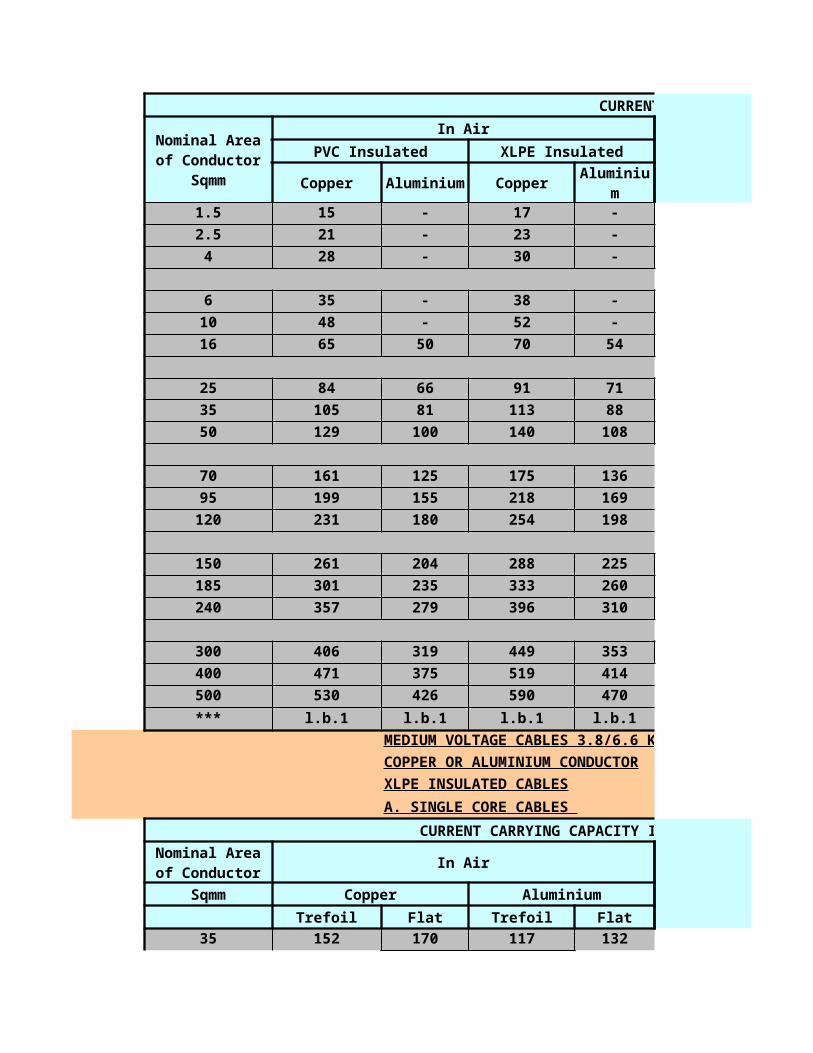
1 x 2.5 U1 GREENYELL. 0.8
1 x 4 R1 GREENYELL. 0.8
1 x 4 U1 GREENYELL. 0.8
1 x 6 R1 GREENYELL. 0.8
1 x 6 U1 GREENYELL. 0.8
1 x 10 R1 GREENYELL. 1
1 x 16 R1 GREENYELL. 1
1 x 25 R1 GREENYELL. 1.2
1 x 50 R1 GREENYELLO. 1.4
1 x 70 R1 GREENYELLO. 1.4
Techincal data
· Temperatures:during installation: 0°C,during operation:-40° upto +70°C
· Min. bending radius:5 x overall diameter
· Others:flame retardant acc. to IEC 332-2
YYRY
Geometrical Data,RM: circular stranded SM: sector-shaped stranded
2 x 1.5 RM 0.8 1 8.2
2 x 2.5 RM 0.8 1 9
2 x 4 RM 1 1 11
3 x 1.5 RM 0.8 1 8.7
3 x 2.5 RM 0.8 1 9.6
3 x 4 RM 1 1 11.7
3 x 6 RM 1 1 12.8
3 x 10 RM 1 1 15
3 x 16 RM 1 1 17.3
3 x 25 SM 1.2 1 17.2
3 x 35 SM 1.2 1 20.6
3 x 50 SM 1.4 1 24.5
3 x 70 SM 1.4 1.2 27.9
3 x 95 SM 1.6 1.2 31.2
3 x120 SM 1.6 1.2 33.7
3 x150 SM 1.8 1.4 38
3 x185 SM 2 1.4 42.9
No. of coresand
crosssection(n/mm2)
Thickn. Of insulation
(mm)
Thickn. Of bedding approx
(mm)over all dia
bedding (mm)

3 x240 SM 2.2 1.6 48.7
4 x 1.5 RM 0.8 1 9.5
4 x 2.5 RM 0.8 1 10.5
4 x 4 RM 1 1 12.8
4 x 6 RM 1 1 14.1
4 x 10 RM 1 1 16.5
4 x 16 RM 1 1 19.5
4 x 25 SM 1.2 1 21.3
4 x 35 SM 1.2 1 23.5
4 x 50 SM 1.4 1.2 28.7
4 x 70 SM 1.4 1.2 31.7
4 x 95 SM 1.6 1.4 36.1
4 x120 SM 1.6 1.4 39.1
4 x150 SM 1.8 1.4 43.1
4 x185 SM 2 1.6 49
4 x240 SM 2.2 1.6 55.5
5 x 1.5 RM 0.8 1 10.4
5 x 2.5 RM 0.8 1 11.6
5 x 4 RM 1 1 14.1
7 x 1.5 RM 0.8 1 11.4
7 x 2.5 RM 0.8 1 12.6
14 x 1.5 RM 0.8 1 15.8
14 x 2.5 RM 0.8 1 18.2
21 x 1.5 RM 0.8 1 19.3
21 x 2.5 RM 0.8 1 21.5
technical data
Temperatures:during installation 0°up to 50°C,during operation: +70°C,under short-circuit: +160°C
· Min. bending radius:8 x overall diameter
· Others:flame retardant acc. to IEC 332/3
PVC/PVC/SWA/PVC
Geometrical Data,RM: circular stranded SM: sector-shaped stranded
2 x 1.5 RE 0.6 0.8 6.9
2 x 2.5 RE 0.7 0.8 8.1
2 x 4 RM 0.8 0.8 10.2
2 x 6 RM 0.8 0.8 11.2
No. of coresand
crosssection(n/mm2)
Thickn. Of insulation
(mm)
Thickn. Of bedding approx
(mm)over all dai
bedding (mm)
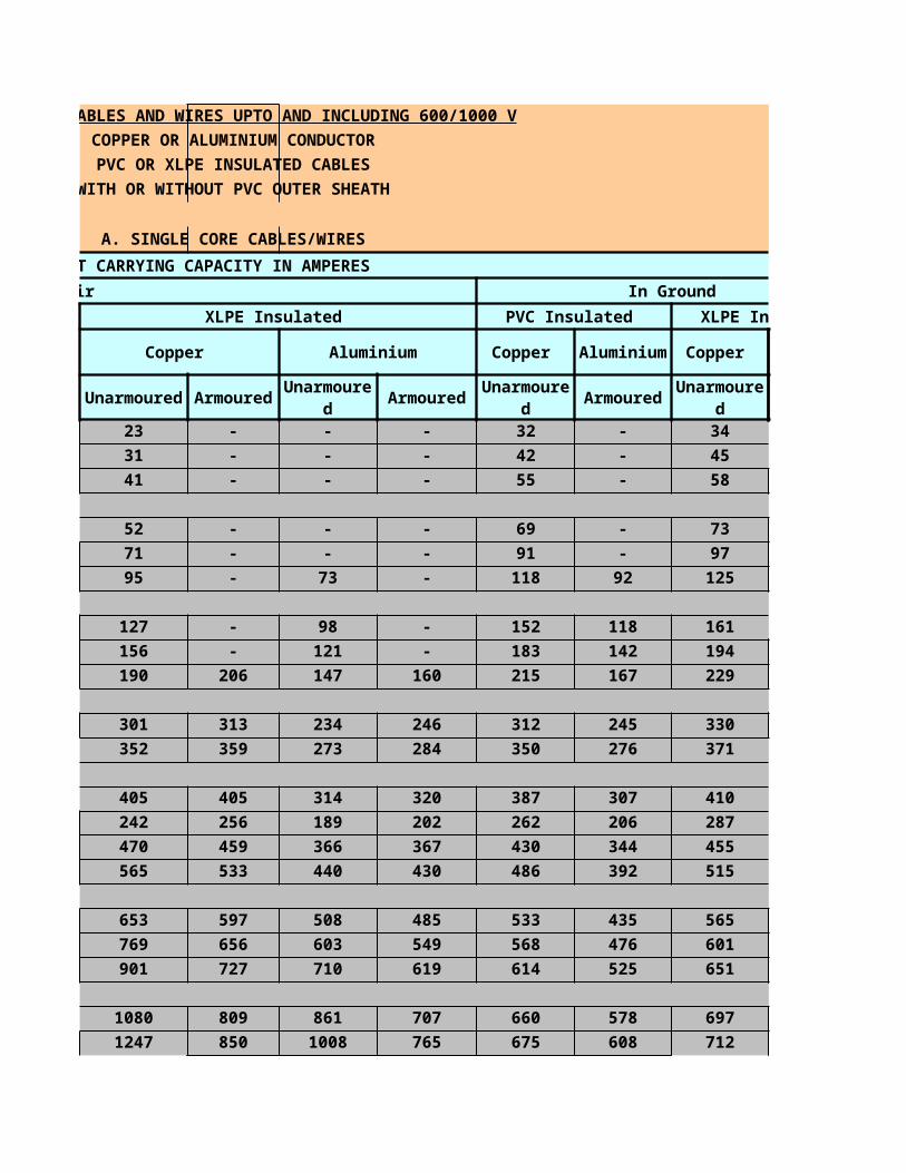
2 x 10 RM 1 0.8 14
2 x 16 RM 1 0.8 16.1
2 x 25 SM 1.2 1 16.6
3 x 1.5 RE 0.6 0.8 7.4
3 x 2.5 RE 0.7 0.8 8.6
3 x 4 RM 0.8 0.8 10.8
3 x 6 RM 0.8 0.8 11.9
3 x 10 RM 1 0.8 14.8
3 x 16 RM 1 0.8 17.3
3 x 25 SM 1.2 1 19.6
3 x 35 SM 1.2 1 23.3
3 x 50 SM 1.4 1 24.5
3 x 70 SM 1.4 1.2 27.9
3 x 95 SM 1.6 1.2 31.2
3 x120 SM 1.6 1.2 33.7
3x150 SM 1.8 1.4 38.0
3x185 SM 2.0 1.4 42.9
4x1.5 RE 0.6 0.8 8.0
4x2.5 RE 0.7 0.8 9.4
4x4 RM 0.8 0.8 11.9
4x6 RM 0.8 0.8 13.1
4x10 RM 1.0 0.8 16.3
4x16 RM 1.0 1.0 19.5
4x25 SM 1.2 1.0 21.3
4x35 SM 1.2 1.0 23.5
4x50 SM 1.4 1.2 28.7
4x70 SM 1.4 1.2 31.7
4x95 SM 1.6 1.2 35.7
4x120 SM 1.6 1.4 39.1
4x150 SM 1.8 1.4 42.1
4x185 SM 2.0 1.6 49.0
7x2.5 RE 0.7 0.8 11.3
8x2.5 RE 0.7 0.8 12.2
14x2.5 RE 0.7 0.8 15.8
21x2.5 RE 0.7 1.0 19.1
techincal data
Temperatures:during installation 0°up to +50°C,during operation +70°C,during short circuit+160°C
Min. bending radius: 8xoverall diameter
others:flame retardant acc. To IEC 732-3
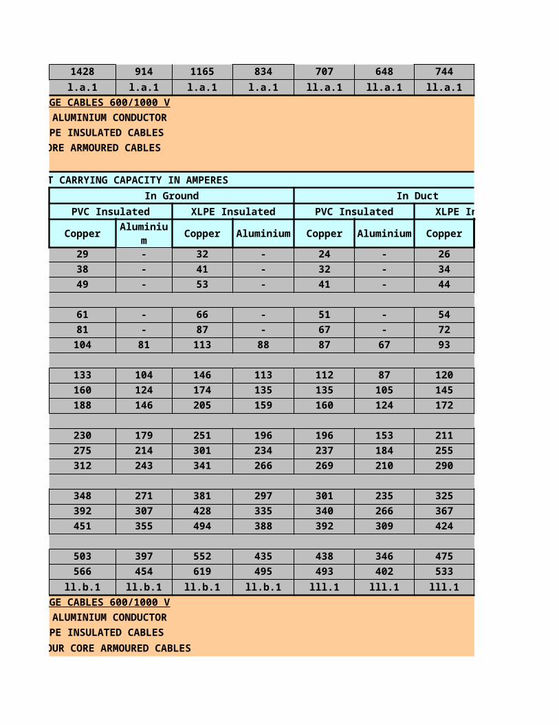
VO-YMvKas mb
Geometrical data,RM: circular stranded SM: sector-shaped stranded
2x1.5 1.5 1.5 0.7
2x2.5 1.5 2.5 0.7
2x4 2.5 4 0.7
3x1.5 1.5 1.5 0.7
3x2.5 1.5 2.5 0.7
3x4 2.5 4 0.7
3x6 4 6 0.7
4x1.5 1.5 1.5 0.7
4x2.5 1.5 2.5 0.7
4x4 2.5 4 0.7
4x6 4 6 0.7
5x1.5 1.5 1.5 0.7
5x2.5 1.5 2.5 0.7
7x1.5 1.5 1.5 0.7
7x2.5 1.5 2.5 0.7
14x1.5 1.5 1.5 0.7
14x2.5 1.5 2.5 0.7
21x1.5 1.5 1.5 0.7
21x2.5 1.5 2.5 0.7
VO-YLK mb
Geometrical data,RM: circular stranded SM: sector-shaped stranded
2x1.5 1.5 1.5 0.7
2x2.5 1.5 2.5 0.7
2x4 2.5 4 0.7
3x1.5 1.5 1.5 0.7
3x2.5 1.5 2.5 0.7
3x4 2.5 4 0.7
No. of cores and cross
section(n/mm2)
Crosssection of earth lead
(mm2)
Equivalent coppercross
section+braid earth lead(mm2)
Thickn. Of insulation(mm)
No. of cores and cross
section(n/mm2)
Crosssection of earth lead
(mm2)
Equivalent coppercross
section+braid earth lead(mm2)
Thickn. Of insulation(mm)

3x6 4 6 0.7
4x1.5 1.5 1.5 0.7
4x2.5 1.5 2.5 0.7
4x4 2.5 4 0.7
4x6 4 6 0.7
5x1.5 1.5 1.5 0.7
5x2.5 1.5 2.5 0.7
7x1.5 1.5 1.5 0.7
7x2.5 1.5 2.5 0.7
14x1.5 1.5 1.5 0.7
14x2.5 1.5 2.5 0.7
21x1.5 1.5 1.5 0.7
21x2.5 1.5 2.5 0.7
VG-YMvKas mb
Geometrical Data,RM: circular stranded SM: sector-shaped stranded
2 x 1.5 RM 1.5 0.7 0.8
2 x 2.5 RM 2.5 0.7 0.8
2 x 4 RM 4 0.7 0.8
3 x 1.5 RM 1.5 0.7 0.8
3 x 2.5 RM 2.5 0.7 0.8
3 x 4 RM 4 0.7 0.8
3 x 6 RM 6 0.7 0.8
3 x 10 RM 10 0.7 0.8
3 x 16 RM 16 0.7 0.8
3 x 25 RM 25 0.9 0.8
3 x 35 RM 25 0.9 0.8
3 x 50 SM 30 1 0.8
3 x 70 SM 35 1.1 0.9
3 x 95 SM 40 1.1 1
3 x 120 SM 50 1.2 1
3 x 150 SM 60 1.4 1.1
3 x 185 SM 75 1.6 1.1
3 x 240 SM 90 1.7 1.2
4 x 1.5 RM 1.5 0.7 0.8
No. of cores and cross
section(n/mm2)
Equivalent copperCross
section of armour mm2)
Thickn. Of insulation(mm)
Thickn. Of bedding(mm)
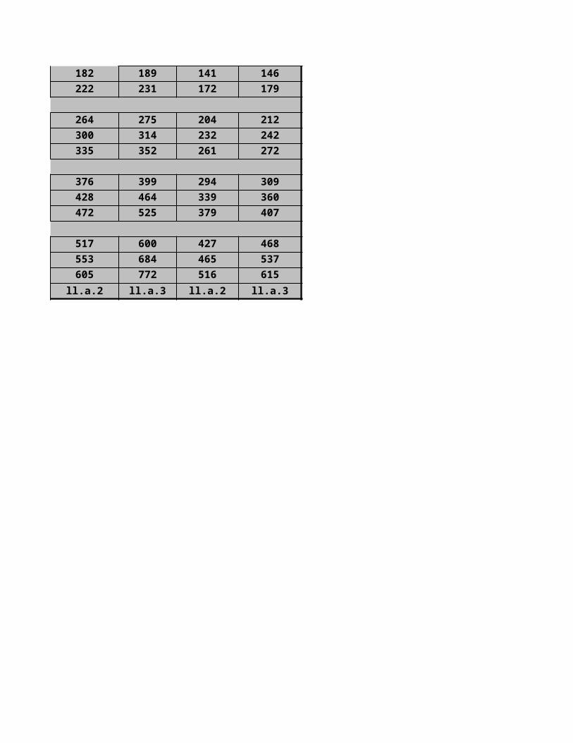
4 x 2.5 RM 2.5 0.7 0.8
4 x 4 RM 4 0.7 0.8
4 x 6 RM 6 0.7 0.8
4 x 10 RM 10 0.7 0.8
4 x 16 RM 16 0.7 0.8
4 x 25 RM 25 0.9 0.9
4 x 35 RM 25 0.9 0.9
4 x 50 SM 30 1 0.9
4 x 70 SM 35 1.1 1
4 x 95 SM 40 1.1 1
4 x 120 SM 50 1.2 1.1
4 x 150 SM 60 1.4 1.1
4 x 185 SM 75 1.6 1.2
4 x 240 SM 90 1.7 1.3
5 x 1.5 RM 1.5 0.7 0.8
5 x 2.5 RM 2.5 0.7 0.8
7 x 1.5 RM 1.5 0.7 0.8
7 x 2.5 RM 2.5 0.7 0.8
14 x 1.5 RM 1.5 0.7 0.8
14 x 2.5 RM 2.5 0.7 0.8
21 x 1.5 RM 1.5 0.7 0.8
21 x 2.5 RM 2.5 0.7 0.8
VG-YLK mb
Geometrical Data,RM: circular stranded SM: sector-shaped stranded
2 x 1.5 RM 1.5 /1 0.7 1.2
2 x 2.5 RM 1.5 /1 0.7 1.2
2 x 4 RM 2.5 /1 0.7 1.2
3 x 1.5 RM 1.5 /1 0.7 1.2
3 x 2.5 RM 1.5 /1 0.7 1.2
3 x 4 RM 2.5 /1 0.7 1.2
3 x 6 RM 4 /1 0.7 1.2
3 x 10 RM 6 /1 0.7 1.2
3 x 16 RM 10 /2 0.7 1.2
No. of cores and
cross section(n/mm2)
Copper crosssection of
the earthing leads no of leads(mm2)
thickn. Ofinsulation(mm)
thickn.of lead sheath(mm)
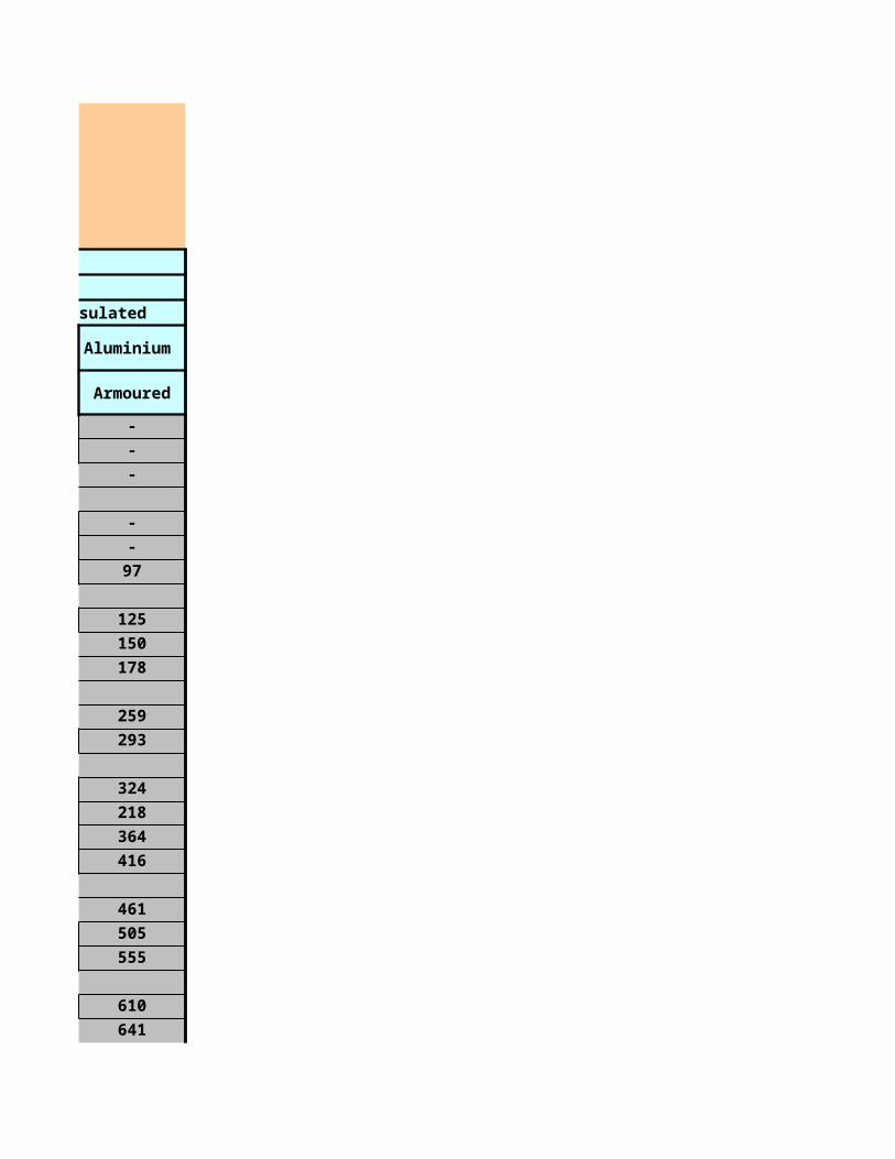
3 x 25 RM 10 /2 0.9 1.2
3 x 35 RM 16 /3 0.9 1.3
3 x 50 SM 16 /3 1 1.3
3 x 70 SM 16 /3 1.1 1.4
3 x 95 SM 20 /4 1.1 1.5
3 x 120 SM 20 /4 1.2 1.6
3 x 150 SM 24 /4 1.4 1.7
3 x 185 SM 24 /4 1.6 1.8
3 x 240 SM 24 /4 1.7 2
4 x 1.5 RM 1.5 /1 0.7 1.2
4 x 2.5 RM 1.5 /1 0.7 1.2
4 x 4 RM 2.5 /1 0.7 1.2
4 x 6 RM 4 /1 0.7 1.2
4 x 10 RM 6 /1 0.7 1.2
4 x 16 RM 10 /2 0.7 1.2
4 x 25 RM 10 /2 0.9 1.3
4 x 35 RM 16 /3 0.9 1.3
4 x 50 SM 16 /3 1.0 1.4
4 x 70 SM 16 /3 1.1 1.5
4 x 95 SM 20 /4 1.1 1.6
4 x120 SM 20 /4 1.2 1.7
4 x150 SM 24 /4 1.4 1.8
4 x185 SM 24 /4 1.6 2.0
5 x 1.5 RM 1.5 /1 0.7 1.2
5 x 2.5 RM 1.5 /1 0.7 1.2
7 x 1.5 RM 1.5 /1 0.7 1.2
7 x 2.5 RM 1.5 /1 0.7 1.2
14 x 1.5 RM 1.5 /1 0.7 1.2
14 x 2.5 RM 1.5 /1 0.7 1.2
21 x 1.5 RM 1.5 /1 0.7 1.2
21 x 2.5 RM 1.5 /1 0.7 1.2
FOR FUTHER CODESCLICK THIS LINIK ALL CABLE CODES
LINKING PDF

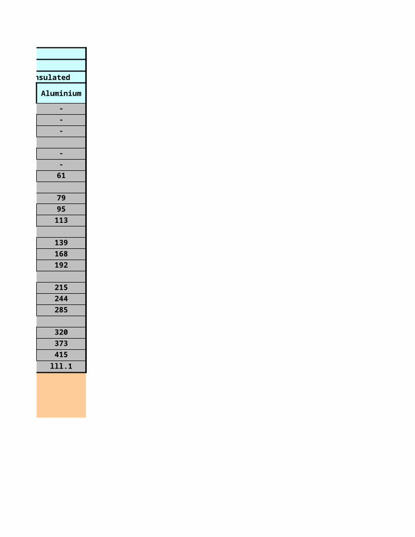
3.5
3.3
4.2
3.9
4.8
4.4
5.4
4.9
6.8
6.4
8
7.3
3.5
3.3
4.2
3.9
4.8
4.4
5.4
4.9
6.8
6.4
8
7.3
3.5
3.3
4.2
3.9
4.8
4.4
5.4
4.9
6.8
6.4
8
7.3
Overall dia approx in mm
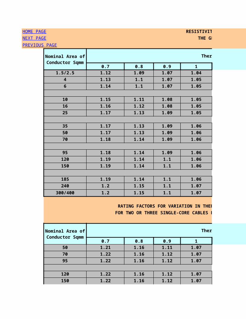
3.5
3.3
4.2
3.9
4.8
4.4
5.4
4.9
6.8
6.4
8
7.3
3.5
3.3
4.2
3.9
4.8
4.4
5.4
4.9
6.8
6.4
8
7.3
3.5
3.3
4.2
3.9
4.8
4.4
5.4
4.9
6.8
6.4
8
7.3
3.5
3.3
4.2

3.9
4.8
4.4
5.4
4.9
6.8
8
9.8
13
15
0.8 1.8 13.4
0.8 1.8 14.2
0.8 1.8 16.2
0.8 1.8 13.9
0.8 1.8 14.2
0.8 1.8 16.9
0.8 1.8 18
0.8 1.8 20.2
0.8 1.8 22.5
1.6 1.8 24
1.6 1.8 27.4
1.6 2 31.7
2 2.1 36.1
2 2.2 39.6
2 2.3 42.3
2.5 2.5 48
2.5 2.7 53.3
armour wire dia
(mm)
thickness of outer sheath (mm)
overall dia(mm)
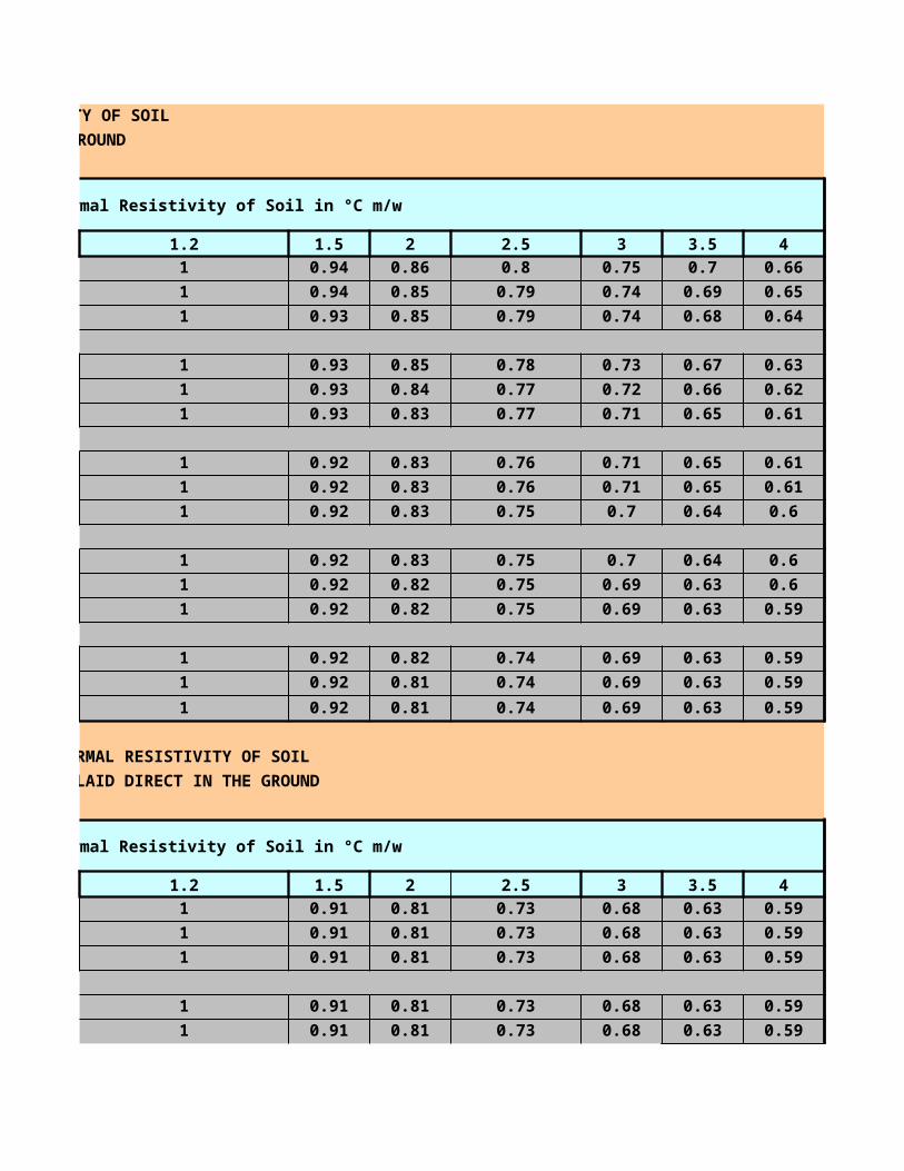
2.5 2.9 59.5
0.8 1.8 14.7
0.8 1.8 15.7
0.8 1.8 18
0.8 1.8 19.3
0.8 1.8 21.7
1.6 1.8 26.3
1.6 1.8 28.1
1.6 1.9 30.5
2 2.1 36.9
2 2.2 40.1
2.5 2.4 45.9
2.5 2.5 49.1
2.5 2.7 53.5
2.5 2.8 59.6
2.5 3.1 66.7
0.8 1.8 15.6
0.8 1.8 16.8
0.8 1.8 19.3
0.8 1.8 16.6
0.8 1.8 17.8
0.8 1.8 21
1.6 1.8 25
1.6 1.8 26.1
1.6 1.8 28.3
Temperatures:during installation 0°up to 50°C,during operation: +70°C,under short-circuit: +160°C
0.9 1.3 11.3
0.9 1.4 12.7
0.9 1.4 14.8
0.9 1.5 16
armour wire dia
(mm)
thickness of outer sheath (mm)
overall dia(mm)
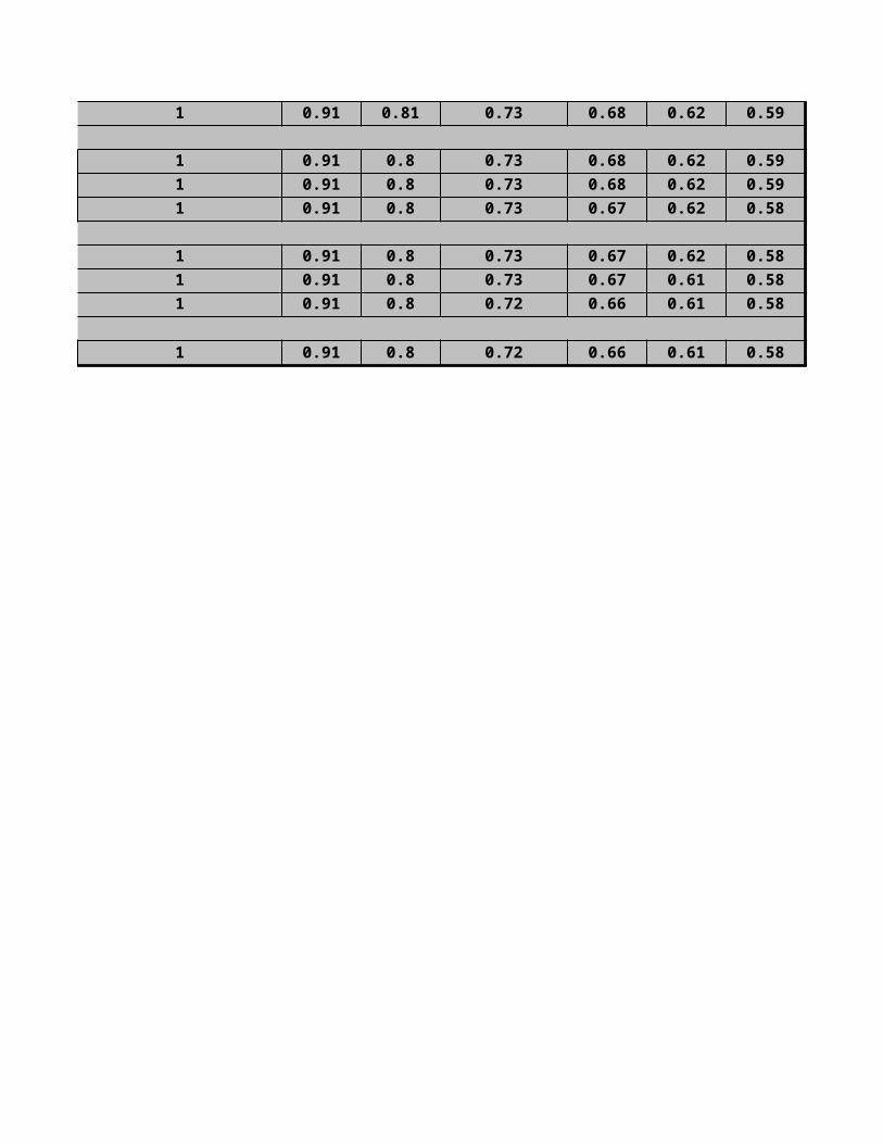
1.25 1.6 19.7
1.25 1.6 21.8
1.6 1.7 23.2
0.9 1.4 12
0.9 1.4 13.2
0.9 1.4 15.4
1.25 1.5 17.4
1.25 1.6 20.5
1.25 1.6 23
1.6 1.7 26.2
1.6 1.8 30.1
1.6 1.9 31.5
2 2 35.9
2 2.1 39.4
2 2.2 42.1
2.5 2.4 47.8
2.5 2.5 52.9
0.9 1.4 12.6
0.9 1.4 14.0
1.25 1.5 17.4
1.25 1.5 18.6
1.25 1.6 22.0
1.6 1.7 26.1
1.6 1.8 28.1
1.6 1.9 30.5
2.0 2.0 36.7
2.0 2.1 39.9
2.0 2.2 44.1
2.5 2.4 48.9
2.5 2.5 53.1
2.5 2.6 59.2
0.9 1.5 16.1
1.25 1.5 17.7
1.25 1.6 21.5
1.6 1.7 25.7
Temperatures:during installation 0°up to +50°C,during operation +70°C,during short circuit+160°C

0.8 7.7 1.8 13.5
0.8 8.5 1.8 14.7
0.8 9.5 1.8 15.7
0.8 8.2 1.8 14.0
0.8 9.0 1.8 14.8
0.8 10.0 1.8 16.2
0.8 11.1 1.8 17.3
0.8 8.9 1.8 14.7
0.8 9.8 1.8 15.6
0.8 10.9 1.8 17.1
0.8 12.1 1.8 18.4
0.8 9.7 1.8 15.5
0.8 10.7 1.8 16.5
0.8 10.1 1.8 15.9
0.8 11.3 1.8 17.1
0.8 14.0 1.8 19.8
0.8 15.7 1.8 21.5
0.8 16.6 1.8 22.4
1.0 19.1 1.8 24.9
1.2 11 1.8 18.3
1.2 11.8 1.8 19.1
1.2 13.2 1.8 20.5
1.2 11.5 1.8 18.8
1.2 12.3 1.8 19.6
1.2 13.7 1.8 21
Thickn. Of beddign(mm
)
dia of overall
bedding(mm)
Thickn. Of outer
sheath(mm)
overall dia of
cable(mm)
Thickn. Of lead
sheath(mm)
dia over lead
sheath(mm)
thickn.of outer
sheath(mm)
over all dia of cable (mm)

1.2 14.8 1.8 22.1
1.2 12.2 1.8 19.5
1.2 13.1 1.8 20.4
1.2 14.7 1.8 22
1.2 15.8 1.8 23.1
1.2 12.8 1.8 20.1
1.2 13.8 1.8 21.1
1.2 14.2 1.8 21.5
1.2 15 1.8 22.3
1.2 17.4 1.8 24.7
1.2 19 1.8 26.3
1.2 20.4 1.8 27.7
1.2 22.3 1.8 29.6
8.2 1 1.8 13.8
9 1 1.8 15.2
10.2 1 1.8 15.8
8.7 1 1.8 14.3
9.6 1 1.8 15.2
10.8 1 1.8 17
11.9 1 1.8 17.5
13.9 1 1.8 20.1
16.3 1 1.8 22.5
19.5 1 1.8 25.7
21.9 0.8F 1.8 28.1
22.3 0.8F 1.8 28.8
25.9 0.8F 2 32.8
28.6 0.8F 2.1 35.7
31.6 0.8F 2.2 38.9
35.7 0.8F 2.4 44.6
40.5 0.8F 2.5 48.1
45.7 1.4F 2.7 55.3
9.4 1 1.8 15
dia of overall
bedding(mm)
dia armourwire-resp.
thickn.
Thickn. Of outer
sheath(mm)
overall dia of
cable(mm)
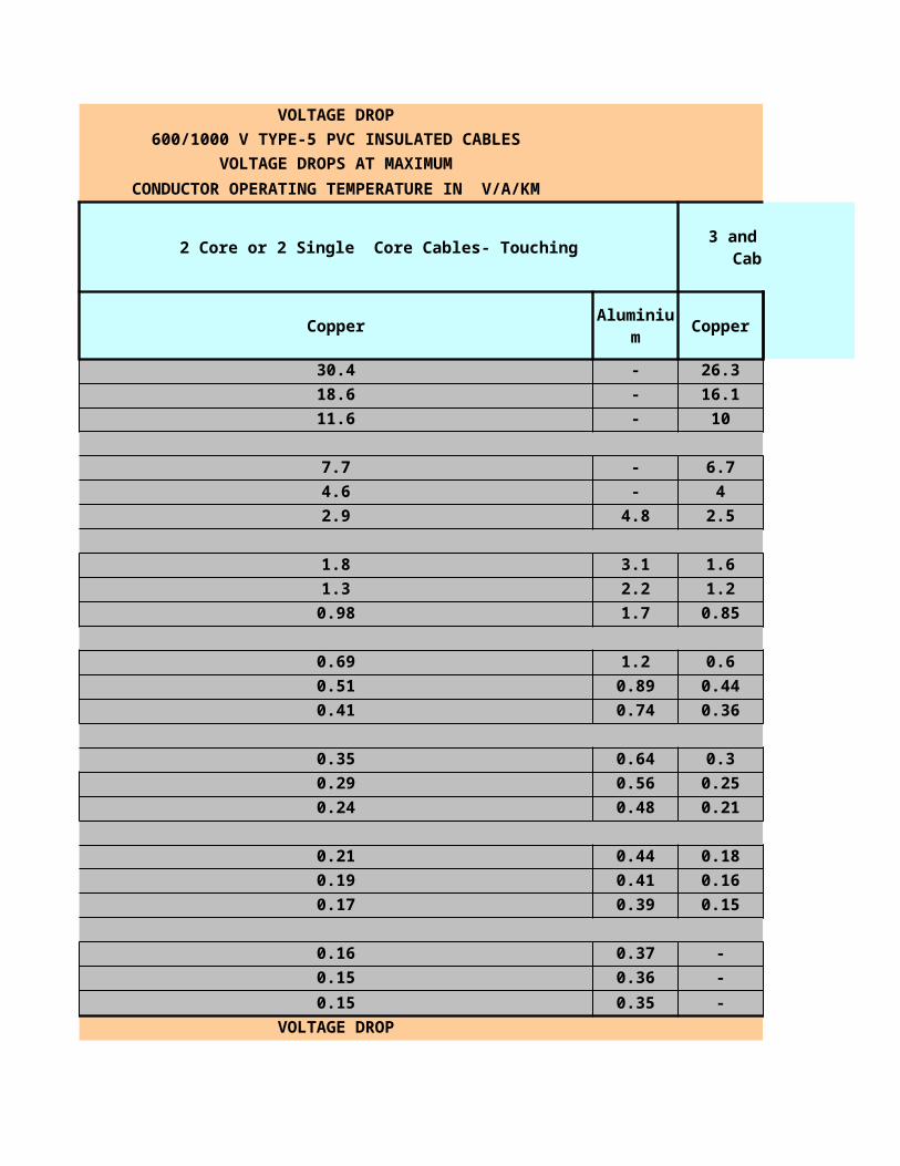
10.4 1 1.8 16.6
11.8 1 1.8 18
13 1 1.8 18.6
15.3 1 1.8 21.5
17.9 1 1.8 24.1
21.6 1 1.8 27.8
24.3 0.8F 1.8 30.4
26.1 0.8F 1.9 32.5
29.8 0.8F 2.1 36.6
32.8 0.8F 2.2 39.8
36.5 0.8F 2.4 43.9
40.5 0.8F 2.5 48.8
46.2 1.4F 2.7 55.8
52.4 1.4F 2.9 62.7
10 1 1.8 16.2
11.1 1 1.8 17.3
10.7 1 1.8 17
12 1 1.8 18.2
15 1 1.8 21.2
16.8 1 1.8 23
18.4 1 1.8 24.6
20.7 1 1.8 26.9
11.5 1 1.8 20.1
12.3 1 1.8 20.9
13.9 1 1.8 22.5
12 1 1.8 20.6
12.9 1 1.8 21.5
14.5 1 1.8 23.1
15.6 1 1.8 24.2
17.6 1 1.8 26.2
20.7 1 1.8 29.3
dia of lead sheath(mm)
armour wire
dia/thickness(mm)
thickness of outer
sheath(mm)
overall dia of
cable(mm)
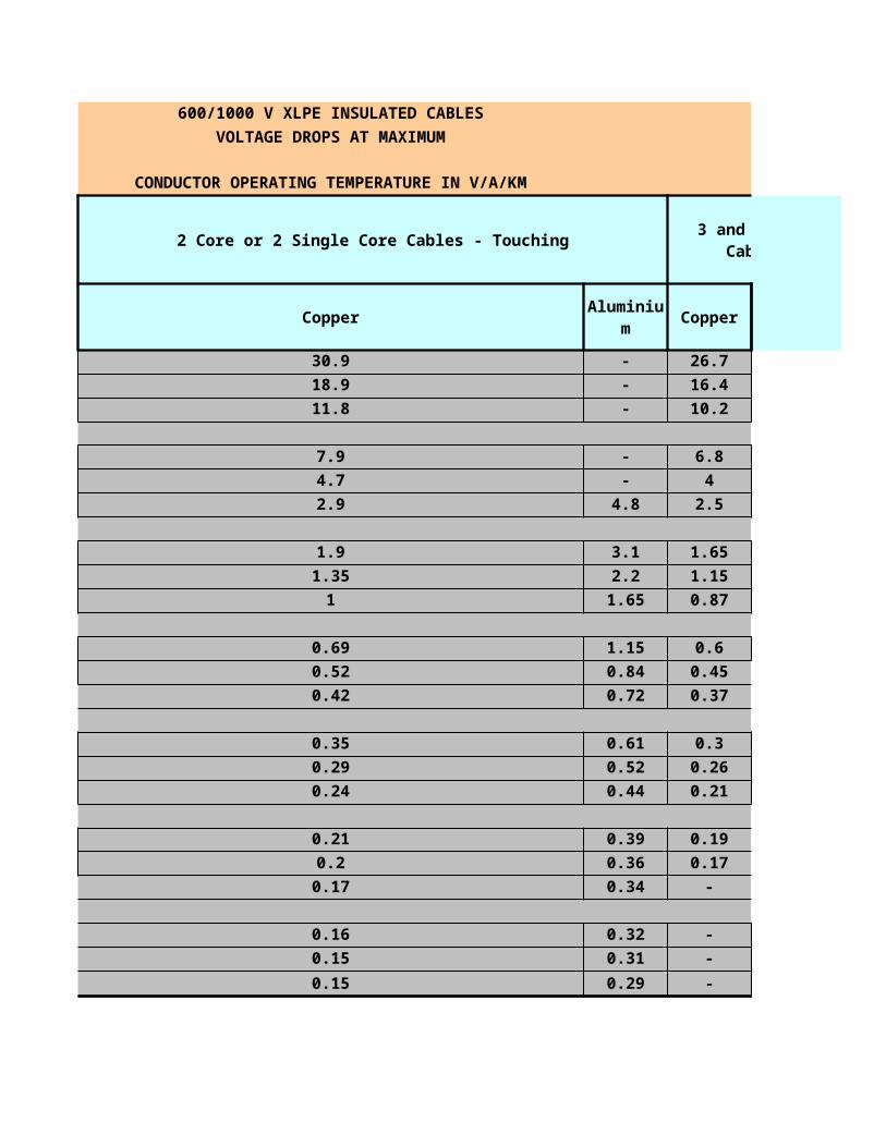
24.3 1 1.8 32.9
27.5 0.8 F 1.9 37
28.2 0.8 F 2 37.6
32.2 0.8 F 2.1 41.4
35.1 0.8 F 2.3 44.2
37.8 1.4 F 2.4 49
42.3 1.4 F 2.6 53.7
47.6 1.4 F 2.8 59.6
53.2 1.4 F 3 66.5
12.7 1.0 1.8 21.3
14.1 1.0 1.8 22.7
15.5 1.0 1.8 24.1
16.7 1.0 1.8 25.3
18.9 1.0 1.8 27.5
22.6 1.0 1.8 30.9
26.5 1.0 1.9 35.3
29.7 0.8 F 2.0 39.4
31.3 0.8 F 2.1 41.4
35.8 0.8 F 2.3 46.5
39.9 0.8 F 2.4 49.4
43.1 0.8 F 2.6 54.9
47.3 0.8 F 2.8 59.7
53.6 1.4 F 3.0 66.6
13.0 1.0 1.8 21.6
14.6 1.0 1.8 23.2
14.0 1.0 1.8 22.6
15.2 1.0 1.8 23.8
18.3 1.0 1.8 26.7
20.2 1.0 1.8 28.6
21.1 1.0 1.8 29.5
23.8 1.0 1.9 32.4
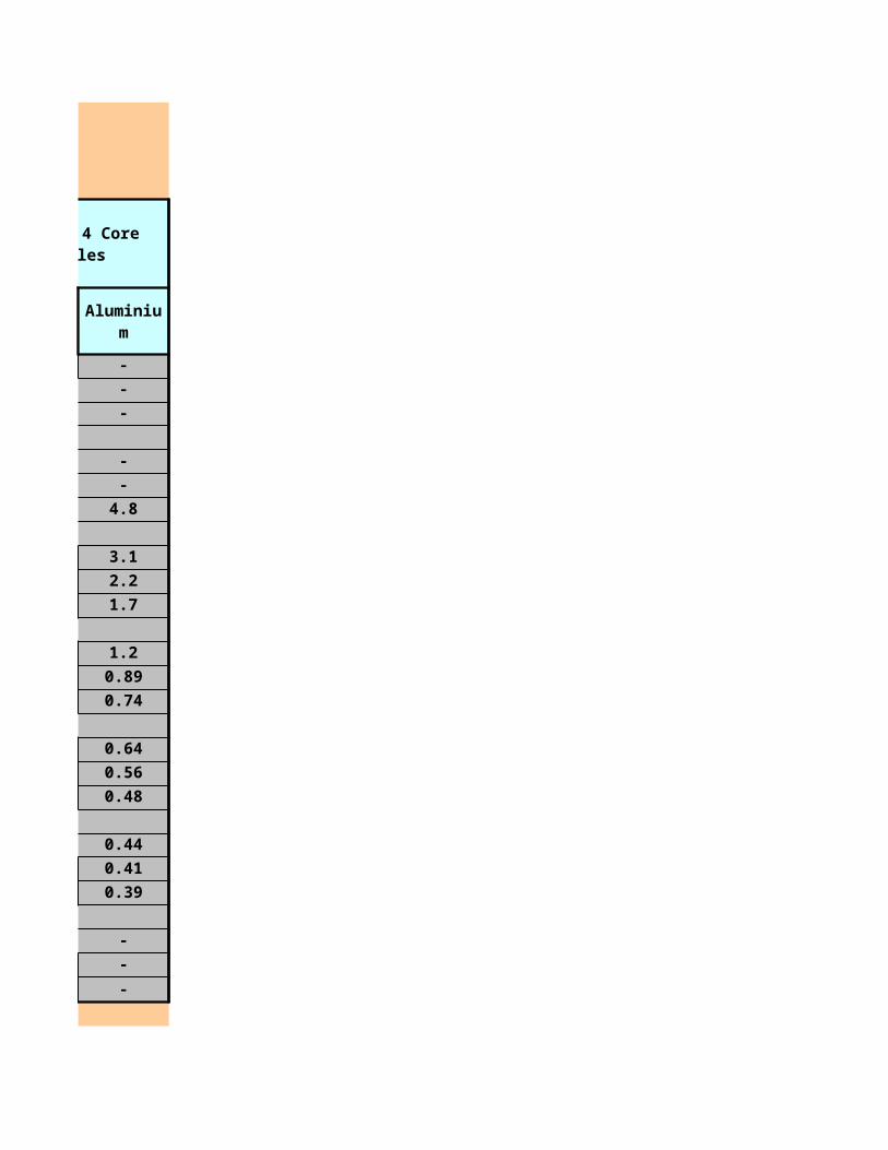
Depth of Laying 600/1000 V Cables
Meter Cables Laid in Ground
0.5 1.026 1.036
0.6 1.015 1.016
0.75 1 1
0.8 0.995 0.995
1 0.974 0.974
1.25 0.964 0.953
1.5 0.954 0.943
1.75 0.944 0.922
2 0.933 0.912
2.5 0.923 0.902
3 0.913 0.891
or More
RATING FACTORS FOR VARIATION IN
AMBIENT TEMPERATURE FOR CABLES LAID IN AIR
25 30
1.35 1.29
1.37 1.3
RATING FACTORS FOR VARIATION IN GROUND TEMPERATURE
FOR CABLES LAID DIRECT IN GROUND OR IN DUCTS
15 20
1.19 1.15
HOME PAGE
PREVIOUS PAGE
Upto 50 Sqmm
70 Sqmm to 300 Sqmm
Ambient Temperature ºC
PVC insulated Cables
XLPE insulated Cables
Ground temperature ºC
PVC insulated Cables

1.16 1.13XLPE insulated
Cables

600/1000 V Cables 1.9/3.3 KV to 19/33 KV Cables
Cables Laid in Ground Cables Laid in Ducts Cables Laid in Ground
Above 300 Sqmm Multicore Upto 300 Sqmm
1.055 1.044 1.026 -
1.023 1.023 1.015 -
1 1 1 -
0.992 0.992 0.995 1.02
0.97 0.971 0.985 1
0.949 0.94 0.974 0.98
0.939 0.93 0.964 0.969
0.918 0.919 0.964 0.959
0.907 0.909 0.954 0.939
0.897 0.898 0.954 0.929
0.876 0.888 0.944 0.918
RATING FACTORS FOR VARIATION IN
AMBIENT TEMPERATURE FOR CABLES LAID IN AIR
35 40 45 50
1.22 1.16 1.09 1.02
1.24 1.17 1.09 1.03
RATING FACTORS FOR VARIATION IN GROUND TEMPERATURE
FOR CABLES LAID DIRECT IN GROUND OR IN DUCTS
25 30 35 40
1.09 1.05 1 0.95
RATING FACTORS FOR DEPTHS OF LAYING FOR CABLES LAID
DIRECT IN GROUND OR IN DUCTS
Single Core
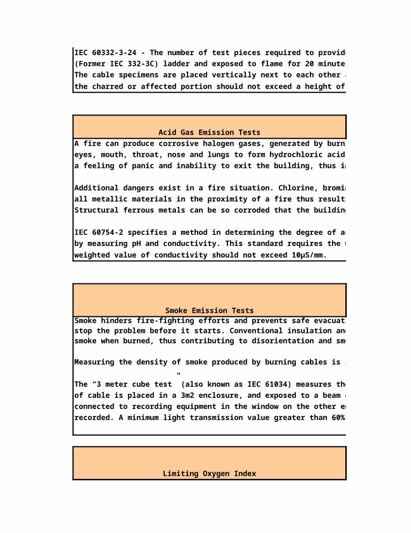
1.08 1.03 1 0.95

1.9/3.3 KV to 19/33 KV Cables
Cables Laid in Ground
-
-
-
1.031
1
0.979
0.969
0.948
0.928
0.918
0.907
52 55 60
1 0.95 0.86
1 0.95 0.88
45
0.89
Above 300 Sqmm
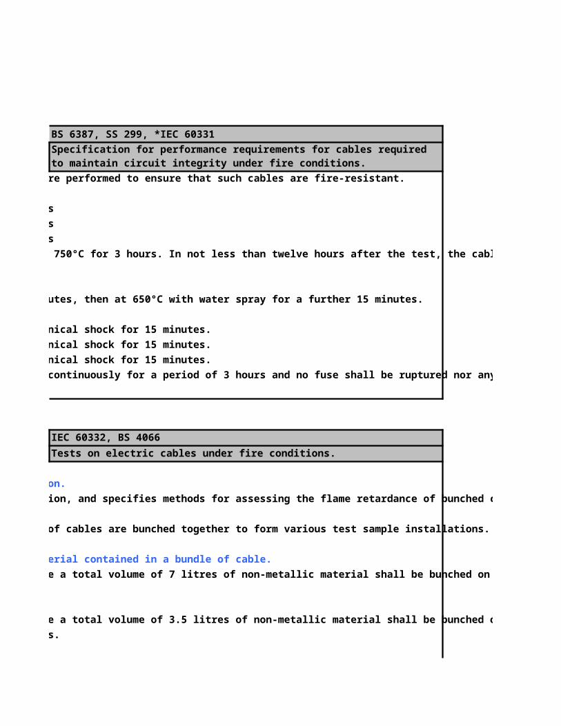
0.9