Embed Size (px)
Citation preview

© Danfoss | 2017.02 VD.KV.A8.02 | 1
Brazed heat exchanger XB06 & Flow-compensated temperature controller IHPT (PN16)
Data sheet
Description
The XB is a brazed plate heat exchanger designed for use with district heating systems (i.e. air conditioning, heating, domestic hot water). XB brazed plate heat exchangers are made with several differently sized heat exchange plates.
The IHPT is flow-compensated temperature controller with ∆p controller built in developed to control instantaneous heating of domestic hot water by means of heat exchanger.
Innovative design enables simple, fast and reliable connection to heat exchanger and most important production of ultra compact and user friendly stations for heating of domestic hot water service.
The capacity of controllers fully covers the needs of domestic hot water for flats, one family houses or dwellings and can be mounted to district heating network directly, to a block of heating systems or central located boiler system in a dwelling house.
The controller is connected to primary heating system as well as cold water system. To avoid risk of leaking from one media to the other the controller is equipped with double sealing. Between both sealings there is a bore to the outside of the valve. In case of leakage from one sealing the media can escape through the bore.
Typical system conditionsDistrict heating systems with varying supply temperature plus high and varying differential pressure and where a high comfort idle temperature is requested.Idle controller is integrated.Controllers have:
- WRAS approval,- ETA VA approval.
Main data:• DN 15• kVS 2.4, 3.0 m3/h• PN 16• Setting range: 45 ... 65 °C (see Setting range section)
• Temperature: Circulation water 2 ... 120 oC• Connections:
- Union nut
XB06 IHPT

Data sheet XB06 & IHPT (PN 16)
2 | © Danfoss | 2017.02 VD.KV.A8.02
Ordering
Example 1:Flow-compensated temperature controller with ∆p controller built in (NO), DN 15, kVS 2.4, PN 16, setting range 45 ... 65 °C, union nut connection
- 1× IHPT DN 15 controller Code No: 003L3875
Option:- 1× Housing of sensor stuffing box Code No: 013U8102
Example 2:Flow-compensated temperature controller with ∆p controller built in (NO), DN 15, kVS 2.4, PN 16, setting range 45 ... 65 °C, union nut connection & brazed heat exchanger XB06 with 26 plates
- 1× Combination DN 15 Code No: 003L3900
IHx Controllers, 90° version - Damped 1)
Picture Type DNkVS Setting range 4)
Connection 2) Code No.(m3/h) (°C)
IHPT 3) 152,4
45 … 65 Union nut003L3875
3,0 003L3877
1) For details see “Application scheme” section2) to heat exchanger3) Controller is delivered with thermostatic actuator with standard sensor and M14 sensor stuffing box (housing of sensor stuffing box is
not delivered, it is available as an accessory)4) see Setting range section
XB06 & IHPT - Damped
Picture Type DNkVS
(m3/h)
Setting range 3)
(°C)
Heat exchanger type
XB 06H-1-26 XB 06H-1-30 XB 06H-1-36
Combination Code No. 2)
IHPT 1) 15
2.4
45 … 65
003L3900 003L3901 003L3902
3.0 003L3903 003L3904 003L3905
1) Controller is delivered with standard sensor and Rp ½” sensor stuffing box incl. housing of sensor stuffing box2) Code number includes one IHPT and one heat exchanger3) see Setting range section
IHPT & XB06 (II) - Damped
Picture Type DNkVS
(m3/h)
Setting range 3)
(°C)
Heat exchanger type
XB 06H-1-16 XB 06H-1-26
Combination Code No. 2)
IHPT 1) 15
2.4
45 … 65
003L3920
3.0 003L3921
1) Controller is delivered with standard sensor and Rp ½” sensor stuffing box incl. housing of sensor stuffing box2) Code number includes one IHPT and two heat exchangers3) see Setting range section
AccessoriesType designations Code No.
Housing of sensor stuffing box 1) 013U81021) Code includes housing and gasket of sensor stuffing box;
R ½ × M14 × 1 mm, rubber EPDM Ø 12,6 × 4 × 6 mm
Ser vice kits
Type designationsSetting range Code No. 1)
(°C) for IHPT
Service thermostat 40 … 60 003L3868
Thermostatic actuator with standard sensor 45 … 65 003L3833
1) For details see “Installation positions” section; sensor is delivered with M14 sensor stuffing box

Data sheet XB06 & IHPT (PN 16)
© Danfoss | 2017.02 | 3VD.KV.A8.02
Secondary side
Technical data *
* Data for XB06 see relevant Data sheet
Nominal diameter DN 15
kVS value of thermostatic controller (kVS,TC)m3/h
2.4 3.0
kVS value of built in ∆p controller (kVS,DP ) 5.0
Controlled ∆p on thermostatic controller (∆pTC) bar 0.16
Min. flow rate on primary side (Q1,min)
l/h
70 100
Max. flow rate on primary side (Q1,max) 1000 1200
Min. flow rate on secondary side (Q2,min) 120
Max. rec. flow rate on secondary side (Q2,max) 1400 4)
Nominal pressure PN 16 3)
Max. differential pressure on primary sidebar
6.0
Max. rec. differential pressure on secondary side 1.0
MediumCirculation water / glycolic water up to 30% 1)
Domestic hot water (chlorine (cl) content max. 200 ppm) 2)
Medium pH Min. 7, max. 10 3)
Medium temperature
ºC
2 ... 120
Setting range 45 … 65
Idle temperature Tset – 8 °C
Max. adm. temperature at sensor 120
Capillary tube length m 0.6
Materials
Housings CuZn21Si3P (CW724R)
Cone and diaphragm support MPPE (Noryl)
Main spindle Stainless steel, mat. No. 1.4404
Diaphragm, O-rings EPDM
Temperature sensor Copper, mat. No. 2.00901) Valid for primary side2) Valid for secondary side3) On primary and secondary side4) at diff. pressure on secondary side (Δp2 ) 1 bar
Classification according to VDI 6003
Type Wash basin 1) Showers 2)
IHPT III III1) Tapping rate changing in steps of 6-12-6 l/min.2) Tapping rate changing in steps of 9-12-9 l/min.
Measured for constant supply temperature of 75 °C and system differential pressure of 0.5 bar.
The min. required differential pressure across primary side of the controller is calculated from the formula:
0.1650.8
Δpk
QΔp
2
TC
2
DPVS,
maxPRIM,minPRIM,
In graph pressure drop on secondary side in relation to the secondary flow can be seen.
* TC - thermostatic controller
Quick suggestion:If the max. flow rate on primary side is below 1 m3/h (1000 l/h) always choose kVS = 2.4 m3/h and if it is higher then choose kVS = 3.0 m3/h.
Data sheet XB06 & IHPT (PN 16)
4 | © Danfoss | 2017.02 VD.KV.A8.02
IHPTTC DP
QC
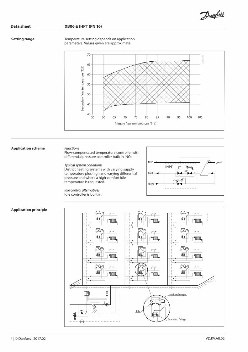
Setting range Temperature setting depends on application parameters. Values given are approximate.
Application principle
FunctionsFlow-compensated temperature controller with differential pressure controller built in (NO)
Typical system conditionsDistrict heating systems with varying supply temperature plus high and varying differential pressure and where a high comfort idle temperature is requested.
Idle control alternativesIdle controller is built in.
Application scheme

Data sheet XB06 & IHPT (PN 16)
© Danfoss | 2017.02 | 5VD.KV.A8.02
ΔpPRIM, MIN
Δpsyst,min
ΔpTC
Δp
exch
ang
er
IHPT
TC DP
QC
Best performance
Sizing Example Instantaneous domestic hot water production requires primary flow of 800 l/h. Minimum system differential pressure is 0.8 bar.
Given data: QPRIM, max = 0.8 m3/h (800 l/h)Δpsyst, min = 0.8 bar (80 kPa)Δpexchanger = 0.1 bar (10 kPa)
The total (available) pressure loss across the primary side of the controller is:
ΔpPRIM,A = Δpsyst,min - Δpexchanger = 0.8 - 0.1
ΔpPRIM,A = 0.7 bar (70 kPa)
Possible pipe pressure losses in tubes, shut-off fittings, heatmeters, etc. are not included.
Select controller acc. to technical data, page 3, with the smallest possible kvs value consideringavailable flow ranges:
kVS, TC = 2.4 m3/h
The other relevant data for this controller are:kVS, DP = 5.0 m3/hΔp TC = 0.16 bar (16 kPa)
The min. required differential pressure across primary side of the selected controller is calculated from the formula:
0.1650.8
Δpk
QΔp
2
TC
2
DPVS,
maxPRIM,minPRIM,
ΔpPRIM,min = 0.19 bar (19 kPa)ΔpPRIM,A > ΔpPRIM,min
0.7 bar > 0.19 bar
Temperature controller Controller must be mounted on cold side of heat exchanger (district heating outlet and domestic cold water inlet side).
IHPT, Termix TPV controllers are delivered with standard sensor.
Standard sensorThe sensor must always be placed warmer than the controller.
Temperature sensorCan be mounted on any direction. For best performance it is recommended to install the sensor facing up.
Strainers installation IIt is strongly recommended to install strainers on both the cold water pipeline and the district heating supply line.
Sensor installation

Data sheet XB06 & IHPT (PN 16)
6 | © Danfoss | 2017.02 VD.KV.A8.02
Function The controller has three main functions that can be mounted in the controller based on application demands:QC Proportional flow controllerTC Thermostatic controllerDP Differential pressure controller
To minimise the risk of calcium deposits on cold water side and sensitivity to high temperatures the controller is mounted on cold side of heat exchanger (district heating outlet and domestic cold water inlet side). In standard applications at standard conditions with Danfoss heat exchanger XB 06 primary return temperature is below 30 °C.
Design
1. Secondary side cone (QC) 2. Moving seat 3. Main body 4. O-ring 5. Differential pressure cone (DP) 6. Main spindle 7. Primary side cone (TC) 8. Stuffing box 9. Thermostat 10. Handle for temperature
setting 11. Secondary side body 12. Circulation connection
plug (3/8”) 13. Temperature sensor 14. Differential pressure moving
seat 15. Washer of sensor stuffing box 16. Gasket of sensor stuffing box 17. Sealing bolt of sensor stuffing
box 18. Primary side body 19. Housing of sensor stuffing box
DP
QC
TC

Data sheet XB06 & IHPT (PN 16)
© Danfoss | 2017.02 | 7VD.KV.A8.02
Function (continuous)
When tapping starts, cold water flows into secondary side of controller ① passes the secondary side cone (QC) ②, leaves the controller ③ and enters the heat exchanger. The pressure drop generated on the orifice is transferred to the diaphragm ④ which transfers the force to the spring ⑫. This results in moving of the main spindle ⑤ to the right which opens the primary side cone ⑥.
The opening results in primary flow entering into controller ⑦, passing integrated differential pressure controller (DP) ⑧, primary side cone (TC) ⑥ and leaving controller ⑨.
The temperature sensor ⑩, mounted to the secondary hot water side is sensing the temperature. If the temperature is deviating from setting temperature the thermostatic element ⑬ will move (open/close) primary side cone ⑥ until desired temperature is reached. Not to influence on tapping flow from thermostatic adjustments the spring ⑫ is mounted between main spindle ⑤ and diaphragm which can be compressed when needed.
When no load (no flow on secondary side) the controller mantains constant temperature in the heat exchanger few degrees below adjusted temperature (Idle temperature).
The differential pressure controller ⑧ controls the pressure over control valve and therefore enables 100 % authority of the controller in all conditions.
By rotating the handle for temperature setting ⑬ the temperature of tapping flow can be adjusted.
Domestic hot water circulation ⑪ connections are placed directly on the controller and therefore minimize the costs for mounting and optimize space for the piping.
Flow-compensated temperature controller IHPT with integrated differential pressure controller
Flow-compensated temperature controller IHPT with integrated differential pressure controller
Data sheet XB06 & IHPT (PN 16)
8 | © Danfoss | 2017.02 VD.KV.A8.02
Settings Temperature settingTemperature setting is adjusted with handle for temperature setting.
By turning it in (+) direction the setting is increased, by turning it in (-) direction the setting is decreased.
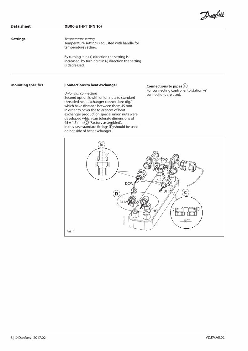
Mounting specifics Connections to heat exchanger
Union nut connectionSecond option is with union nuts to standard threaded heat exchanger connections (fig.1) which have distance between them 45 mm. In order to cover the tolerances of heat exchanger production special union nuts were developed which can tolerate dimensions of 45 ± 1,5 mm (Factory assembled).In this case standard fittings should be used on hot side of heat exchanger.
Connections to pipes For connecting controller to station ¾” connections are used.
Fig. 1

Data sheet XB06 & IHPT (PN 16)
© Danfoss | 2017.02 | 9VD.KV.A8.02
Dimensions

Data sheet XB06 & IHPT (PN 16)
10 | © Danfoss | 2017.02 VD.KV.A8.02

Data sheet XB06 & IHPT (PN 16)
© Danfoss | 2017.02 | 11VD.KV.A8.02

VD.KV.A8.0212 | © Danfoss | DHS-SRMT/SI | 2017.02
Danfoss can accept no responsibility for possible errors in catalogues, brochures and other printed material. Danfoss reserves the right to alter its products without notice. This also applies to products already on order provided that such alterations can be made without subsequential changes being necessary eady agreed.All trademarks in this material are property of the respective companies. Danfoss and the Danfoss logotype are trademarks of Danfoss A/S. All rights reserved.
Data sheet XB06 & IHPT (PN 16)