Embed Size (px)
Citation preview

Page 1/12
JUMO GmbH & Co. KGDelivery address:Mackenrodtstraße 14,
36039 Fulda, GermanyPostal address: 36035 Fulda, GermanyPhone: +49 661 6003-0Fax: +49 661 6003-607e-mail: [email protected]: www.jumo.net
JUMO Instrument Co. Ltd.JUMO HouseTemple Bank, RiverwayHarlow, Essex CM20 2DY, UKPhone: +44 1279 635533Fax: +44 1279 635262e-mail: [email protected]: www.jumo.co.uk
JUMO Process Control, Inc.8 Technology BoulevardCanastota, NY 13031, USAPhone: 315-697-JUMO
1-800-554-JUMOFax: 315-697-5867e-mail: [email protected]: www.jumo.us
Data Sheet 70.6000
Pen recorder with text printingand LED dot-matrix display
Brief descriptionThe LOGOLINE 500 recorder family comprises three pen recorders:Type LL.v-44u, Type LL.v-44uj and Type LL.v-44ud.Each pen recorder offers up to three measurement inputs for recording the measure-ments, which are isolated from each other by optocouplers. The measurements can beread by pointers against scales, or are shown on the display. Channel 1 can be used tooutput text in addition to the measurement trace.All channels are zeroed using Hall sensors.The watchdog monitors the pen recorder function and triggers a restart in the event of afault. The configuration data are stored permanently in EEPROM. On a power failure, thereal-time clock is buffered by the recorders.The standard current and voltage signals can be connected on all recorders. On typesLL.v-44u and LL.v-44ud, input signals can additionally be from thermocouples, resistancethermometers, resistance transmitters and potentiometers. The necessary linerarization isperformed automatically.Optional expansions are available for the types LL.v-44u and LL.v-44ud. Eight logic inputsare available for additional operating functions. In most cases, a math and logic modulepermits the recorder to be individually adapted to complex measurement tasks. An exter-nal relay module ER8 for rail mounting supplements the pen recorders by eight switchingoutputs. A 2-wire transmitter can be operated from an isolated supply.
Type LL3v-44u/ …Type LL3v-44uj/ …
Type LL3v-44ud/ …
Overview of functions
1. available as an option
LL.v-44u LL.v-44uj LL.v-44ud
1/2/3 analog inputs(configurable andelectrically isolated)
ThermocouplesResistance thermometerResistance transmitterPotentiometerVoltageCurrent
VoltageCurrent
ThermocouplesResistance thermometerResistance transmitterPotentiometerVoltageCurrent
8 logic inputs1 for floating contacts orPLC levelFunctions:- External texts
- Binary-linked text
- External stop
- External speed
- Event counter
- External scaling
- External report
for floating contacts orPLC levelFunctions:- External texts
- Binary-linked text
- External stop
- External speed
- Event counter
- External scaling
- External report
Outputs1 - Interface for8 relay outputs
- Supply for 2-wiretransmitter
- Interface for8 relay outputs
- Supply for 2-wiretransmitter
Recording - Measurement traces
- Text printing
- Meas. traces
- Text printing(restricted)
- Measurement traces
- Text printing
Setup interface for configurationand parameter setting
for configurationand parameter setting
RS422/RS485interface1
Data transfer from and tothe recorder
Data transfer from and tothe recorder
2009-02-05/00324162
Applicationsk Failure and fault analysis
k Compliance with official regulations
k Reports for users and customers
k Monitoring of processes
k Optimization of procedures
Approvals

Data Sheet 70.6000JUMO GmbH & Co. KG • 36035 Fulda, Germany Page 2/12
Technical dataThermocouple input (LL.v-44u and LL.v-44ud)
Resistance thermometer input (LL.v-44u and LL.v-44ud)
Designation Range Linearization accuracy1
Fe-Con L DIN 43710Fe-Con J EN 60584Cu-Con U DIN 43710Cu-Con T EN 60584NiCr-Ni K EN 60584NiCr-Con E EN 60584NiCrSi-NiSi N EN 60584Pt10Rh-Pt S EN 60584Pt13Rh-Pt R EN 60584Pt30Rh-Pt6Rh B EN 60584
-200 to +900°C-210 to +1200°C-200 to +600°C-270 to +400°C-270 to +1372°C-270 to +1000°C-270 to +1300°C-50 to +1768°C-50 to +1768°C
0 — 1820°C
±0.1%±0.1% above -200°C±0.1% above -150°C±0.1% above -150°C±0.1% above -80°C±0.1% above -100°C±0.1% above -100°C±0.15% above 0°C±0.15% above 0°C±0.15% above 400°C
Shortest span Types L, J, U, T, K, E, N:Types S, R, B:
100°C500°C
Range start/end within the range limits, freely programmable in 0.1°C steps
Cold junction Pt 100 internal, external Pt 100 in 3-wire circuitor external cold junction thermostat
Cold junction accuracy (internal) ± 1°C
Cold junction temperature (external) -20 to +100°C can be set via the setup software
Measurement time 240msec for all three channels
Input filter second-order digital filter; filter constant adjustable from 0 — 10.0sec
Special features programmable also in °F; customer-specific linearization
1. The linearization accuracy refers to the maximum measurement span.
Designation Connection Range Linearization accuracy Meas. current
Pt 100 DIN 2/3-wire2/3-wire4-wire4-wire
-200 to +100°C-200 to +850°C-200 to +100°C-200 to +850°C
±0.4°C±0.8°C±0.4°C±0.5°C
400μA400μA400μA400μA
Pt 100 JIS 2/3-wire2/3-wire4-wire4-wire
-200 to +100°C-200 to +649°C-200 to +100°C-200 to +649°C
±0.4°C±0.8°C±0.4°C±0.5°C
400μA400μA400μA400μA
Pt 500 DIN 2/3-wire2/3-wire4-wire4-wire
-200 to +100°C-200 to +850°C-200 to +100°C-200 to +850°C
±0.4°C±0.8°C±0.4°C±0.5°C
50μA50μA50μA50μA
Pt 1000 DIN 2/3-wire2/3-wire4-wire4-wire
-200 to +100°C-200 to +850°C-200 to +100°C-200 to +850°C
±0.4°C±0.8°C±0.4°C±0.5°C
50μA50μA50μA50μA
Ni 100 2/3-wire2/3-wire4-wire4-wire
-60 to +100°C-60 to +180°C-60 to +100°C-60 to +180°C
±0.4°C±0.8°C±0.4°C±0.5°C
400μA400μA400μA400μA
Connection type 2-, 3- or 4-wire circuit
Shortest span 15°C
Sensor lead resistance max. 30 Ω per core in 3-wire circuitmax. 15Ω per core in 2-wire circuit
Range start/end within the limits, freely programmable in 0.1°C steps
Measurement time 240msec for all three channels
Input filter second-order digital filter; filter constant adjustable from 0 — 10sec
Special features programmable also in °F; customer-specific linearization
2009-02-05/00324162
Data Sheet 70.6000JUMO GmbH & Co. KG • 36035 Fulda, Germany Page 3/12
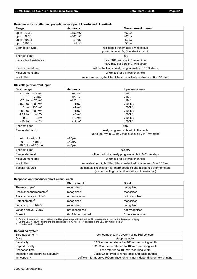
Resistance transmitter and potentiometer input (LL.v-44u and LL.v-44ud)
DC voltage or current input
Response on transducer short-circuit/break
Recording system
Range Accuracy Measurement current
up to 130Ωup to 390Ωup to 1600Ωup to 3900Ω
±150mΩ±300mΩ
±1.6Ω ±2 Ω
400μA400μA50μA50μA
Connection type resistance transmitter: 3-wire circuitpotentiometer: 2-, 3- or 4-wire circuit
Shortest span 6ΩSensor lead resistance max. 30Ω per core in 3-wire circuit
max. 15Ω per core in 2-wire circuit
Resistance values within the limits, freely programmable in 0.1Ω steps
Measurement time 240msec for all three channels
Input filter second-order digital filter; filter constant adjustable from 0 to 10.0sec
Basic range Accuracy Input resistance
-15 to +77mV0 — 170mV
-76 to + 76mV-162 to +880mV
0 — 1930mV-880 to +880mV-1.84 to +10V
0 — 22V-10 to +10V
±80μV±120 μV±120 μV
±1mV±1mV±1mV±6mV
±12mV±12mV
>1MΩ>1MΩ>1MΩ>500kΩ>500kΩ>500kΩ>500kΩ>500kΩ>500kΩ
Shortest span 5mV
Range start/end freely programmable within the limits(up to 999mV in 0.01mV steps, above 1V in 1mV steps)
-4 to +21mA0 — 45mA
-20.5 to +20.5mA
±20μA±40μA±40μA
Shortest span 0.5mA
Range start/end within the limits, freely programmable in 0.01mA steps
Measurement time 240msec for all three channels
Input filter second-order digital filter; filter constant adjustable from 0 — 10.0sec
Special features adjustable linearization for thermocouples and resistance thermometers (for connecting transmitters without linearization)
Short-circuit1 Break1
Thermocouple2 recognized recognized
Resistance thermometer2 recognized recognized
Resistance transmitter2 not recognized not recognized
Potentiometer2 recognized recognized
Voltage up to 170mV recognized recognized
Voltage above 170mV not recognized not recognized
Current 0mA is recognized 0mA is recognized
1. On the LL.v-44u and the LL.v-44uj, the fiber pens are positioned to 0%. No message is shown on the 7-segment display.On the LL.v-44ud, the fiber pens are positioned to 0%. “>>>>>>” appears in the LED dot matrix display.
2. LL.v-44u and LL.v-44ud
Zero adjustment self-compensating system using Hall sensorsDrive stepping motorSensitivity 0.2% or better referred to 100mm recording widthReproducibility 0.25% or better referred to 100mm recording widthResponse time 1sec referred to 100mm recording widthIndication and recording accuracy Class 0.5 referred to range limits and basic rangesInk capacity sufficient for approx. 1000m trace; on channel 1 depending on text printing
2009-02-05/00324162
Data Sheet 70.6000JUMO GmbH & Co. KG • 36035 Fulda, Germany Page 4/12
Electrical data
Housing
Approvals/marks of conformity
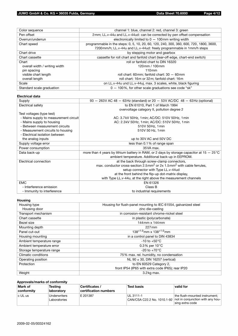
Color sequence channel 1: blue, channel 2: red, channel 3: greenPen offset 2mm; LL.v-44u and LL.v-44ud: can be corrected by pen offset compensationOverrun/underrun electronically limited to 0 — 100mm writing widthChart speed programmable in the steps: 0, 5, 10, 20, 60, 120, 240, 300, 360, 600, 720, 1800, 3600,
7200mm/h; LL.v-44u and LL.v-44ud: freely programmable in 1mm/h stepsChart drive by stepping motor and gearboxChart cassette cassette for roll chart and fanfold chart (tear-off edge, chart-end switch)Chart
overall width / writing widthpin spacingvisible chart lengthoverall length
roll or fanfold chart to DIN 16320120mm / 100mm
110mmroll chart: 60mm; fanfold chart: 30 — 60mmroll chart: 16m or 32m; fanfold chart: 16m
Scale on LL.v-44u und LL.v-44uj, max. 3 scales, white, black figuringStandard scale graduation 0 — 100%, for other scale graduations see code “sk”
Supply 93 — 263V AC 48 — 63Hz (standard) or 20 — 53V AC/DC 48 — 63Hz (optional)Electrical safety
Test voltages (type test)- Mains supply to measurement circuit- Mains supply to housing- Between measurement circuits- Measurement circuits to housing- Electrical isolation between
the analog inputs
to EN 61010, Part 1 of March 1994overvoltage category II, pollution degree 2
AC: 3.7kV 50Hz, 1min; AC/DC: 510V 50Hz, 1min AC: 2.3kV 50Hz, 1min; AC/DC: 510V 50Hz, 1min
510V 50Hz, 1min510V 50 Hz, 1min
up to 30V AC and 50V DCSupply voltage error less than 0.1% of range spanPower consumption 35VA max.Data back-up more than 4 years by lithium battery in RAM, or 2 days by storage capacitor at 15 — 25°C
ambient temperature. Additional back-up in EEPROM.Electrical connection at the back through screw-clamp connectors,
max. conductor cross-section 2.5mm2 or 2x 1.5mm2 with cable ferrules,setup connector with Type LL.v-44ud
at the front behind the flip-up dot-matrix display,with Type LL.v-44u, at the right above the measurement channels
EMC- Interference emission- Immunity to interference
EN 61326Class B
to industrial requirements
Housing typeHousing door
Housing for flush-panel mounting to IEC 61554, galvanized steelzinc die-casting
Transport mechanism in corrosion-resistant chrome-nickel steelChart cassette in plastic (polycarbonate)Bezel size 144mm x 144mmMounting depth 227mmPanel cut-out 138+1.0mm x 138+1.0mmHousing mounting in a control panel to DIN 43834Ambient temperature range -10 to +50°CAmbient temperature error 0.3% per 10°CStorage temperature range -20 to +70°CClimatic conditions 75% max. rel. humidity, no condensationOperating position NL 90 ± 30, DIN 16257 (vertical)Protection to EN 60529 Category 2,
front IP54 (IP65 with extra code IP65); rear IP20Weight 3.2kg max.
Mark of conformity
Testing laboratory
Certificates / certification numbers
Test basis valid for
c UL us Underwriters Laboratories
E 201387 UL 3111-1CAN/CSA C22.2 No. 1010.1-92
the flush-mounted instrument;not in conjunction with any hou-sing extra code
2009-02-05/00324162
Data Sheet 70.6000JUMO GmbH & Co. KG • 36035 Fulda, Germany Page 5/12
Operating modesLL.v-44u and LL.v-44ud
Chart speedsThe LL.v-44u and LL.v-44ud recorders canbe programmed with four different operat-ing modes for the chart speed.
1. Normal operation
2. Limit operationIf the measurement goes above/below theprogrammed limits, the recorder switchesto the speed which has been programmedunder “limit operation”.
3. External operationA signal on one of the logic inputs at theback of the recorder switches to the speedprogrammed under “external speed”.
4. Timed operationChart speed which is operative within aprogrammable time span.
Zoom (plot area)In zoom operation, an enlarged recording ismade of a section of the full range.
Presentation range (offset)This parameter is used to define the pres-entation range of a trace on the chart.This assists the evaluation of traces whichare close together or overlapping.
LL.v-44ujThis recorder only features the operatingmode “normal operation”. Zoom and offsetfunctions are not applicable.
Text printingLL.v-44u and LL.v-44udText printing is used for comments on therecorded trace and for event recording.Priorities can be assigned to the texts toserve as abort criteria during simultaneoustext printing requests. Text printing can be separately configuredfor each text, either time-optimized or dur-ing printing of the recording traces.Text printing facilities:- Time, date
- Scaling of the channels
- Change of chart speed
- Recording start/end text
- Eight external texts1
- 16 binary-linked external texts1
- Eight relay texts1
- Event counter1
- Report
- Print test
- Service print
1. extra code zf is required.
2009-02-05/00324162
LL.v-44ujFor LOGOLINE 500 junior, text printing islimited to- Time, date
- Change of chart speed
- Text at recording start and end
- Print test
- Service print.
Printing priorities and the printing modecan not be set.
Extra codesLL.v-44u and LL.v-44ud
Logic inputs (zf)Both types can be equipped with eight log-ic inputs.The inputs can be operated through float-ing contacts or by the following voltage lev-els:inactive 0 — 5Vactive 20 — 35VThe voltages must be applied for 0.5sec.
Functions available:- External start/stop
- Chart speed change to “external speed”
- Text printing
- Start/stop external report
- Start scaling print
- Event counter
Supply for 2-wire transmitter (zf)An isolated supply for a 2-wire transmitteris available.24V ± 5% DC 45mA
Serial interface for ER8 (zf)The external relay module ER8 can be op-erated using the serial interface.
RS422/RS485 interfaceThis interface is intended for communica-tion with higher-level systems (e. g. bus system or PC).It can be used to- read out the measurements,
- monitor operating states, and
- transmit text and values to therecorders.
AccessoriesLL.v-44u and LL.v-44ud
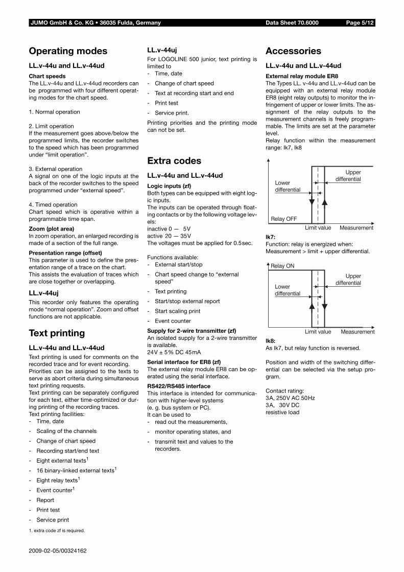
External relay module ER8The Types LL. v-44u and LL.v-44ud can beequipped with an external relay moduleER8 (eight relay outputs) to monitor the in-fringement of upper or lower limits. The as-signment of the relay outputs to themeasurement channels is freely program-mable. The limits are set at the parameterlevel.Relay function within the measurementrange: lk7, lk8
lk7:Function: relay is energized when: Measurement > limit + upper differential.
lk8:As lk7, but relay function is reversed.
Position and width of the switching differ-ential can be selected via the setup pro-gram.
Contact rating:3A, 250V AC 50Hz 3A, 30V DC resistive load

2009-02-05/00324162
Data Sheet 70.6000JUMO GmbH & Co. KG • 36035 Fulda, Germany Page 6/12
Indications and controlsLL.v-44u and LL.v-44uj
Indications and controls LL.v-44ud
4-digit 7-segment display
scale, channel 1
chart
keys for operating and programming
setup interface
door
channel marker label
housing to IEC 61554 for flush-panel mounting, galvanized steel
fiber pen, channel 1, blue
24-place 5 x 5 LED dot-matrix display
fiber pen, channel 3, green
door
channel marker label
housing to IEC 61554 for flush-panel mounting, galvanized steel
chart
keys for operation and programming
setup interface
Operation andconfigurationOn the recorder
LL.v-44uj and LL.v-44udAll parameters can be programmed fromthe instrument keys. A 7-segment or anLED dot-matrix display are available tomonitor the parameters.
LL.v-44uThe following parameters can be alteredfrom the keys:- Language
- Date and time
- Summer time
- Relay limit settings
- Chart speed
- Print test
- Service print
Via setup program for PC
LL.v-44u and LL.v-44udMore conveniently than by the instrumentkeys, all parameters can be configured viathe PC setup program.Additional functions are:- Customer-specific linearization
- Setting the printing mode of texts (“Overwrite trace” or “Interrupt trace”)
- Different settings (also for several instruments) can be managed.
- Reading out and altering the settingof a configured instrument
- Archiving and printing the setting
Customer-specific linearizationIn the setup program there is a choice be-tween linear, square law and cube law line-arization. There can be up to 41 calibrationpoints for linear and square law lineariza-tion, and up to 61 calibration points forcube law linearization. These calibrationpoints are used to determine the coeffi-cients for polynomials which are definedfor each section, so that even a few calibra-tion points produce a smooth graph.Accuracy: depends on the shape of thegraph and the selected linearization.
LanguageLL.v-44u and LL.v-44ujThe language setting (English, German,French) appears in the print-out only.
LL.v-44udThe language which was set (English, Ger-man, French) appears in the print-out andin the LED dot-matrix display.

Data Sheet 70.6000JUMO GmbH & Co. KG • 36035 Fulda, Germany Page 7/12
Example of a recordingwith text print-out for Type LLv-44u (ud)The factory-setting provides for all the measurement traces to be printedin the range 0—100%, i.e. across the entire chart width.
(1) Print the time (with every fourth print-out, the current chart speed, the programmed instrument name or the date are printed alternately)
(2) Print-out at the start of the recording (begin text)
(3) Print-out at the end of the recording (end text)
(4) Relay text
(5) Current time(6) Speed change to normal operation
(7) Speed change to limit operation
(8) Relay text on exceeding the limit(9) Current time
(10)Print-out of scaling with channel number, pen color,channel name and unit.
(11)Begin text
In the example above, the measurement traces are printed out in normalmode, i.e. all traces share the entire width of the chart (0 — 100mm). The presentation range can be selected freely on the chart for each trace.This assists the evaluation, in particular of traces which are close to eachother or which overlap. The traces in the example on the right have thusbeen arranged over three sections of the chart.
2009-02-05/00324162
(1)
(2)
(3)
(5)
(6)
(7)
(8)
(4)
(9)
(10)
(11)

Data Sheet 70.6000JUMO GmbH & Co. KG • 36035 Fulda, Germany Page 8/12
Connection diagramRear view with screw-clamp connectors
Connection Diagram
Supply as on label N neutralL1 linePE protective earth
N (L-)L1 (L+)PE
Analog inputs Input 1 Input 2 Input 3
Connector Connector Connector
Thermocouple
1. 2. 3.
Thermocouplewith external Pt 100 cold junction
Resistance thermometer/potentiometer in 2-wire circuit
*Rcomp = Rline
Resistance thermometer/potentiometer in 3-wire circuit
Resistance thermometer/potentiometer in 4-wire circuit
2009-02-05/00324162

Data Sheet 70.6000JUMO GmbH & Co. KG • 36035 Fulda, Germany Page 9/12
Analog inputs Input 1 Input 2 Input 3
Connector Connector Connector
Resistance transmitterwith 3-wire connection
1. 2. 3.
Voltage input up to 170mV
Voltage input above 170mV
Current input
Connector
External relay module ER8 Communicationwith externalrelay module
8.
Supply for external 2-wiretransmitter
24V ± 5% 45mA
Digital operating inputs Contact operationLOW = ROFF 100kΩ min.HIGH = RON 50Ω max.
contact no. 7 = logic input 1...
contact no. 14 = logic input 8
Min. pulse duration:HIGH 500msecLOW 500msec
Voltage operationLOW = 0 — 5V DC (inactive)HIGH = 20 — 35V DC (active)
contact no. 7 = logic input 1...
contact no. 14 = logic input 8
Serial interfaceRS422/RS485
Communication withhigher-level systems
9.
A = startS = sliderE = end
2009-02-05/00324162
Data Sheet 70.6000JUMO GmbH & Co. KG • 36035 Fulda, Germany Page 10/12
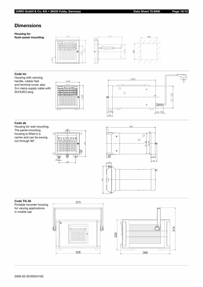
Dimensions
Housing for flush-panel mounting
Code tmHousing with carryinghandle, rubber feetand terminal cover, also3m mains supply cable withSCHUKO plug
Code abHousing for wall mounting.The panel-mountinghousing is fitted in acarrier and can be swungout through 90°.
Code TG-35Portable recorder housingfor varying applicationsin mobile use
373
326 366
22
6
31
4
2009-02-05/00324162
Data Sheet 70.6000JUMO GmbH & Co. KG • 36035 Fulda, Germany Page 11/12
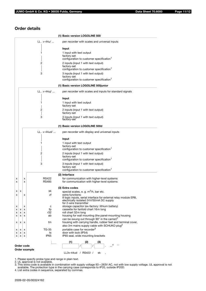
Order details
(1) Basic version LOGOLINE 500
LL . v-44u/ ... pen recorder with scales and universal inputs
Input
1 1 input with text outputfactory-setconfiguration to customer specification1
2 2 inputs (input 1 with text output)factory-setconfiguration to customer specification1
3 3 inputs (input 1 with text output)factory-setconfiguration to customer specification1
(1) Basic version LOGOLINE 500junior
LL . v-44uj/ ... pen recorder with scales and inputs for standard signals
Input
1 1 input with text outputfactory-set
2 2 inputs (input 1 with text output)factory-set
3 3 inputs (input 1 with text output)factory-set
(1) Basic version LOGOLINE 500d
LL . v-44ud/ ... pen recorder with display and universal inputs
Input
1 1 input with text outputfactory-setconfiguration to customer specification1
2 2 inputs (input 1 with text output)factory-setconfiguration to customer specification1
3 3 inputs (input 1 with text output)factory-setconfiguration to customer specification1
(2) Interfacex x RS422 for communication with higher-level systemsx x RS485 for communication with higher-level systems
(3) Extra codesx x sk special scales, e. g. m3/h, bar etc.x x zf extra functions:
8 logic inputs, serial interface for external relay module ER8,electrically isolated 24V/50mA DC supplyfor 2-wire transmitter
x x c storage capacitor (ex-factory: lithium battery)x x x fp cassette for fanfold chart 16m longx x x r32 roll chart 32m longx x x ab housing for wall mounting (the panel-mounting housing
can be swung out through 90° in the carrier)2
x x x tm housing with carrying handle, rubber feet and terminal cover,also 3m mains supply cable with SCHUKO plug2
x x x TG-35 portable case for recorder3
x x x ts door with lock (IP54)x x x IP65 IP65 seal, wide mounting brackets
(1) (2) (3)Order code / / , ...4 ...
Order exampleLL3v-44ud / RS422 / sk ,
1. Please specify probe type and range in plain text.2. UL approval is not available.3. This extra code is available in combination with supply voltage 93—263V AC, not with low supply voltage. UL approval is not
available. The protection type in the carrying case corresponds to IP20, outside IP20D.4. List extra codes in sequence, separated by commas.
2009-02-05/00324162
Data Sheet 70.6000JUMO GmbH & Co. KG • 36035 Fulda, Germany Page 12/12
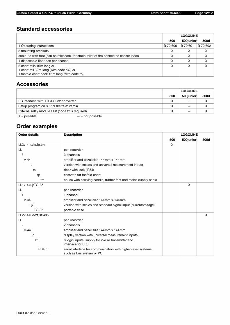
Standard accessories
Accessories
Order examples
LOGOLINE
500 500junior 500d
1 Operating Instructions B 70.6001 B 70.6011 B 70.6021
2 mounting brackets X X X
cable-tie with foot (can be released), for strain relief of the connected sensor leads X X X
1 disposable fiber pen per channel X X X
2 chart rolls 16m long or1 chart roll 32m long (with code r32) or1 fanfold chart pack 16m long (with code fp)
X X X
LOGOLINE
500 500junior 500d
PC interface with TTL/RS232 converter X — X
Setup program on 3.5" diskette (2 items) X — X
External relay module ER8 (code zf is required) X — X
X = possible — = not possible
Order details Description LOGOLINE
500 500junior 500d
LL3v-44u/ts,fp,tm X
LL pen recorder
3 3 channels
v-44 amplifier and bezel size 144mm x 144mm
u version with scales and universal measurement inputs
ts door with lock (IP54)
fp cassette for fanfold chart
tm house with carrying handle, rubber feet and mains supply cable
LL1v-44uj/TG-35 X
LL pen recorder
1 1 channel
v-44 amplifier and bezel size 144mm x 144mm
uj/ version with scales and standard signal input (current/voltage)
TG-35 portable case
LL2v-44ud/zf,RS485 X
LL pen recorder
2 2 channels
v-44 amplifier and bezel size 144mm x 144mm
ud display version with universal measurement inputs
zf 8 logic inputs, supply for 2-wire transmitter andinterface for ER8
RS485 serial interface for communication with higher-level systems,such as bus system or PC
2009-02-05/00324162