Embed Size (px)
Citation preview

Data Reference GuideVersion 4
Volume I: Vehicle Tests
April 1997(Codes updated 8/15/97)
U.S. Department of Transportation
http://www-nrd.nhtsa.dot.gov/nrd10/software

[This page intentionally left blank]

NHTSA Vehicle Data Reference Guide TOC-1
TABLE OF CONTENTS
PREFACE . . . . . . . . . . . . . . . . . . . . . . . . . . . . . . . . . . . . . . . . . . . . . . . . . . . . . . . . . . . i
INTRODUCTION . . . . . . . . . . . . . . . . . . . . . . . . . . . . . . . . . . . . . . . . . . . . . . . . . . . . . . . . . . . . . . . . . iv
CHAPTER 1: GENERAL TEST INFORMATION . . . . . . . . . . . . . . . . . . . . . . . . . . . . . . . 1-1TSTNO - Test Number . . . . . . . . . . . . . . . . . . . . . . . . . . . . . . . . . . . . . . . . . . . . . . . . . . . . . . . . . . 1-1
VERSION NUMBER . . . . . . . . . . . . . . . . . . . . . . . . . . . . . . . . . . . . . . . . . . . . . . . . . . . . . . . . . . . 1-1
TITLE - Contract or Study Title . . . . . . . . . . . . . . . . . . . . . . . . . . . . . . . . . . . . . . . . . . . . . . . . . . . 1-1
TSTOBJ - Test Objectives . . . . . . . . . . . . . . . . . . . . . . . . . . . . . . . . . . . . . . . . . . . . . . . . . . . . . . . 1-1
TSTDAT - Test Date . . . . . . . . . . . . . . . . . . . . . . . . . . . . . . . . . . . . . . . . . . . . . . . . . . . . . . . . . . . 1-1
TSTPRF - Test Performer . . . . . . . . . . . . . . . . . . . . . . . . . . . . . . . . . . . . . . . . . . . . . . . . . . . . . . . . 1-1
CONNO - Contract Number . . . . . . . . . . . . . . . . . . . . . . . . . . . . . . . . . . . . . . . . . . . . . . . . . . . . . . 1-2
TSTREF - Test Reference Number . . . . . . . . . . . . . . . . . . . . . . . . . . . . . . . . . . . . . . . . . . . . . . . . 1-2
TSTTYP - Test Type . . . . . . . . . . . . . . . . . . . . . . . . . . . . . . . . . . . . . . . . . . . . . . . . . . . . . . . . . . . . 1-2
TSTCFN - Test Configuration . . . . . . . . . . . . . . . . . . . . . . . . . . . . . . . . . . . . . . . . . . . . . . . . . . . . . 1-2
TKSURF - Test Track Surface . . . . . . . . . . . . . . . . . . . . . . . . . . . . . . . . . . . . . . . . . . . . . . . . . . . . 1-2
TKCOND - Test Track Condition . . . . . . . . . . . . . . . . . . . . . . . . . . . . . . . . . . . . . . . . . . . . . . . . . . 1-2
TEMP - Ambient Temperature . . . . . . . . . . . . . . . . . . . . . . . . . . . . . . . . . . . . . . . . . . . . . . . . . . . . 1-3
RECTYP - Type of Recorder . . . . . . . . . . . . . . . . . . . . . . . . . . . . . . . . . . . . . . . . . . . . . . . . . . . . . . 1-3
LINK - Data Link to Recorder . . . . . . . . . . . . . . . . . . . . . . . . . . . . . . . . . . . . . . . . . . . . . . . . . . . . . 1-3
CLSSPD - Closing Speed . . . . . . . . . . . . . . . . . . . . . . . . . . . . . . . . . . . . . . . . . . . . . . . . . . . . . . . . 1-3
IMPANG - Impact Angle . . . . . . . . . . . . . . . . . . . . . . . . . . . . . . . . . . . . . . . . . . . . . . . . . . . . . . . . . 1-3
OFFSET - Offset Distance . . . . . . . . . . . . . . . . . . . . . . . . . . . . . . . . . . . . . . . . . . . . . . . . . . . . . . . 1-4
IMPPNT - Side Impact Point . . . . . . . . . . . . . . . . . . . . . . . . . . . . . . . . . . . . . . . . . . . . . . . . . . . . . 1-4
TOTCRV - Total Number of Curves . . . . . . . . . . . . . . . . . . . . . . . . . . . . . . . . . . . . . . . . . . . . . . . 1-4
TSTCOM - Test Commentary . . . . . . . . . . . . . . . . . . . . . . . . . . . . . . . . . . . . . . . . . . . . . . . . . . . . . 1-4
CHAPTER 2: VEHICLE INFORMATION . . . . . . . . . . . . . . . . . . . . . . . . . . . . . . 2-1TSTNO - Test Number . . . . . . . . . . . . . . . . . . . . . . . . . . . . . . . . . . . . . . . . . . . . . . . . . . . . . . . . . . 2-1
VEHNO - Test Vehicle Identification Number . . . . . . . . . . . . . . . . . . . . . . . . . . . . . . . . . . . . . . . . 2-1
MAKE - Vehicle Make . . . . . . . . . . . . . . . . . . . . . . . . . . . . . . . . . . . . . . . . . . . . . . . . . . . . . . . . . . 2-1
MODEL - Vehicle Model . . . . . . . . . . . . . . . . . . . . . . . . . . . . . . . . . . . . . . . . . . . . . . . . . . . . . . . . 2-1
YEAR - Vehicle Model Year . . . . . . . . . . . . . . . . . . . . . . . . . . . . . . . . . . . . . . . . . . . . . . . . . . . . . . 2-1
NHTSANO - NHTSA Number . . . . . . . . . . . . . . . . . . . . . . . . . . . . . . . . . . . . . . . . . . . . . . . . . . . . 2-1

Table of Contents
TOC-2 NHTSA Vehicle Data Reference Guide
CHAPTER 2 (continued)BODY - Body Type . . . . . . . . . . . . . . . . . . . . . . . . . . . . . . . . . . . . . . . . . . . . . . . . . . . . . . . . . . . . . 2-2
VIN - Manufacturer Vehicle Identification Number . . . . . . . . . . . . . . . . . . . . . . . . . . . . . . . . . . . . 2-2
ENGINE - Engine Type . . . . . . . . . . . . . . . . . . . . . . . . . . . . . . . . . . . . . . . . . . . . . . . . . . . . . . . . . . 2-2
ENGDSP - Engine Displacement . . . . . . . . . . . . . . . . . . . . . . . . . . . . . . . . . . . . . . . . . . . . . . . . . . 2-2
TRANSM - Transmission Type . . . . . . . . . . . . . . . . . . . . . . . . . . . . . . . . . . . . . . . . . . . . . . . . . . . 2-2
VEHTWT - Vehicle Test Weight . . . . . . . . . . . . . . . . . . . . . . . . . . . . . . . . . . . . . . . . . . . . . . . . . . 2-2
WHLBAS - Wheelbase . . . . . . . . . . . . . . . . . . . . . . . . . . . . . . . . . . . . . . . . . . . . . . . . . . . . . . . . . . 2-2
VEHLEN - Vehicle Length . . . . . . . . . . . . . . . . . . . . . . . . . . . . . . . . . . . . . . . . . . . . . . . . . . . . . . . 2-3
VEHWID - Vehicle Width . . . . . . . . . . . . . . . . . . . . . . . . . . . . . . . . . . . . . . . . . . . . . . . . . . . . . . . 2-3
VEHCG - Vehicle Center of Gravity Distance Behind Front Axle . . . . . . . . . . . . . . . . . . . . . . . . . 2-3
STRSEP - Steering Column Shear Capsule Separation . . . . . . . . . . . . . . . . . . . . . . . . . . . . . . . . . 2-3
COLMEC - Steering Column Collapse Mechanism . . . . . . . . . . . . . . . . . . . . . . . . . . . . . . . . . . . . 2-3
MODIND - Vehicle Modification Indicator . . . . . . . . . . . . . . . . . . . . . . . . . . . . . . . . . . . . . . . . . . 2-3
MODDSC - Description of Vehicle Modification . . . . . . . . . . . . . . . . . . . . . . . . . . . . . . . . . . . . . . 2-4
BX1 - BX21 - Pretest Vehicle Measurement Data . . . . . . . . . . . . . . . . . . . . . . . . . . . . . . . . . . . . . 2-4
VEHSPD - Vehicle Speed . . . . . . . . . . . . . . . . . . . . . . . . . . . . . . . . . . . . . . . . . . . . . . . . . . . . . . . . 2-5
CRBANG - Crabbed Angle . . . . . . . . . . . . . . . . . . . . . . . . . . . . . . . . . . . . . . . . . . . . . . . . . . . . . . 2-5
PDOF - Principal Direction of Force . . . . . . . . . . . . . . . . . . . . . . . . . . . . . . . . . . . . . . . . . . . . . . . 2-5
BMPENG - Bumper Engagement . . . . . . . . . . . . . . . . . . . . . . . . . . . . . . . . . . . . . . . . . . . . . . . . . . 2-5
SILENG - Sill Engagement . . . . . . . . . . . . . . . . . . . . . . . . . . . . . . . . . . . . . . . . . . . . . . . . . . . . . . . 2-5
APLENG - A-Pillar Engagement . . . . . . . . . . . . . . . . . . . . . . . . . . . . . . . . . . . . . . . . . . . . . . . . . . . 2-6
DPD1-DPD6 - Damage Profile Distances . . . . . . . . . . . . . . . . . . . . . . . . . . . . . . . . . . . . . . . . . . . . 2-6
VDI - Vehicle Damage Index . . . . . . . . . . . . . . . . . . . . . . . . . . . . . . . . . . . . . . . . . . . . . . . . . . . . . 2-10
LENCNT - Total Length of Indentation . . . . . . . . . . . . . . . . . . . . . . . . . . . . . . . . . . . . . . . . . . . . 2-10
DAMDST - Distance Between Center of Damaged Area and Center of Gravity Axis . . . . . . . 2-10
CRHDST - Maximum Crush Distance . . . . . . . . . . . . . . . . . . . . . . . . . . . . . . . . . . . . . . . . . . . . . 2-14
AX1 - AX21 - Post-test Vehicle Measurement Data . . . . . . . . . . . . . . . . . . . . . . . . . . . . . . . . . . 2-14
CARANG - Angle of Moving Test Cart . . . . . . . . . . . . . . . . . . . . . . . . . . . . . . . . . . . . . . . . . . . 2-16
VEHOR - Vehicle Orientation on Moving Cart . . . . . . . . . . . . . . . . . . . . . . . . . . . . . . . . . . . . . . 2-16
VEHCOM - Vehicle Commentary . . . . . . . . . . . . . . . . . . . . . . . . . . . . . . . . . . . . . . . . . . . . . . . . . 2-16

Table of Contents
NHTSA Vehicle Data Reference Guide TOC-3
CHAPTER 3: BARRIER INFORMATION . . . . . . . . . . . . . . . . . . . . . . . . . . . . . . 3-1TSTNO - TEST NUMBER . . . . . . . . . . . . . . . . . . . . . . . . . . . . . . . . . . . . . . . . . . . . . . . . . . . . . . . 3-1
BARRIG - Rigid or Deformable Barrier . . . . . . . . . . . . . . . . . . . . . . . . . . . . . . . . . . . . . . . . . . . . . 3-1
BARSHP - Barrier Shape . . . . . . . . . . . . . . . . . . . . . . . . . . . . . . . . . . . . . . . . . . . . . . . . . . . . . . . . 3-1
BARANG - Angle of Fixed Barrier . . . . . . . . . . . . . . . . . . . . . . . . . . . . . . . . . . . . . . . . . . . . . . . . 3-1
BARDIA - Diameter of Pole Barrier . . . . . . . . . . . . . . . . . . . . . . . . . . . . . . . . . . . . . . . . . . . . . . . 3-2
BARCOM - Barrier Commentary . . . . . . . . . . . . . . . . . . . . . . . . . . . . . . . . . . . . . . . . . . . . . . . . . . 3-2
CHAPTER 4: OCCUPANT INFORMATION . . . . . . . . . . . . . . . . . . . . . . . . . . . . 4-1TSTNO - Test Number . . . . . . . . . . . . . . . . . . . . . . . . . . . . . . . . . . . . . . . . . . . . . . . . . . . . . . . . . . 4-1
VEHNO - Test Vehicle Identification Number . . . . . . . . . . . . . . . . . . . . . . . . . . . . . . . . . . . . . . . . 4-1
OCCLOC - Occupant Location . . . . . . . . . . . . . . . . . . . . . . . . . . . . . . . . . . . . . . . . . . . . . . . . . . . . 4-1
OCCTYP - Occupant Type . . . . . . . . . . . . . . . . . . . . . . . . . . . . . . . . . . . . . . . . . . . . . . . . . . . . . . . 4-1
OCCAGE - Occupant Age . . . . . . . . . . . . . . . . . . . . . . . . . . . . . . . . . . . . . . . . . . . . . . . . . . . . . . . . 4-1
OCCSEX - Occupant Sex . . . . . . . . . . . . . . . . . . . . . . . . . . . . . . . . . . . . . . . . . . . . . . . . . . . . . . . . 4-2
OCCHT - Occupant Height . . . . . . . . . . . . . . . . . . . . . . . . . . . . . . . . . . . . . . . . . . . . . . . . . . . . . . 4-2
OCCWT - Occupant Weight . . . . . . . . . . . . . . . . . . . . . . . . . . . . . . . . . . . . . . . . . . . . . . . . . . . . . 4-2
MTHCAL - Method of Calibration . . . . . . . . . . . . . . . . . . . . . . . . . . . . . . . . . . . . . . . . . . . . . . . . . 4-2
DUMSIZ - Dummy Size Percentile . . . . . . . . . . . . . . . . . . . . . . . . . . . . . . . . . . . . . . . . . . . . . . . . . 4-2
DUMMAN - Dummy Manufacturer . . . . . . . . . . . . . . . . . . . . . . . . . . . . . . . . . . . . . . . . . . . . . . . . 4-2
DUMMOD - Dummy Modification . . . . . . . . . . . . . . . . . . . . . . . . . . . . . . . . . . . . . . . . . . . . . . . . . 4-3
DUMDSC - Description of the Dummy . . . . . . . . . . . . . . . . . . . . . . . . . . . . . . . . . . . . . . . . . . . . . 4-3
CLEARANCE DISTANCES - Clearance Distances Between Test Occupant and Vehicle
Components . . . . . . . . . . . . . . . . . . . . . . . . . . . . . . . . . . . . . . . . . . . . . . . . . . . . . . . . . . . . 4-3
SEPOSN - Seat Position . . . . . . . . . . . . . . . . . . . . . . . . . . . . . . . . . . . . . . . . . . . . . . . . . . . . . . . . . 4-6
CNTRH1 - First Contact Region for Head . . . . . . . . . . . . . . . . . . . . . . . . . . . . . . . . . . . . . . . . . . . 4-6
CNTRH2 - Second Contact Region for Head . . . . . . . . . . . . . . . . . . . . . . . . . . . . . . . . . . . . . . . . . 4-7
CNTRC1 - First Contact Region for Chest or Abdomen . . . . . . . . . . . . . . . . . . . . . . . . . . . . . . . . 4-7
CNTRC2 - Second Contact Region for Chest or Abdomen . . . . . . . . . . . . . . . . . . . . . . . . . . . . . . 4-7
CNTRL1 - First Contact Region for Legs . . . . . . . . . . . . . . . . . . . . . . . . . . . . . . . . . . . . . . . . . . . . 4-7
CNTRL2 - Second Contact Region for Legs . . . . . . . . . . . . . . . . . . . . . . . . . . . . . . . . . . . . . . . . . . 4-7
HIC - Head Injury Criterion . . . . . . . . . . . . . . . . . . . . . . . . . . . . . . . . . . . . . . . . . . . . . . . . . . . . . . . . 4-7
T1 - Lower Boundary of HIC Time Interval . . . . . . . . . . . . . . . . . . . . . . . . . . . . . . . . . . . . . . . . . . 4-7
T2 - Upper Boundary of HIC Time Interval . . . . . . . . . . . . . . . . . . . . . . . . . . . . . . . . . . . . . . . . . . 4-8

Table of Contents
TOC-4 NHTSA Vehicle Data Reference Guide
CHAPTER 4 (continued)
CLIP3M - Thorax Region Peak Acceleration Measurement . . . . . . . . . . . . . . . . . . . . . . . . . . . . . . 4-8
LFEM - Left Femur Peak Load Measurement . . . . . . . . . . . . . . . . . . . . . . . . . . . . . . . . . . . . . . . . 4-8
RFEM Right Femur Peak Load Measurement . . . . . . . . . . . . . . . . . . . . . . . . . . . . . . . . . . . . . . . . 4-8
CSI - Chest Severity Index . . . . . . . . . . . . . . . . . . . . . . . . . . . . . . . . . . . . . . . . . . . . . . . . . . . . . . . . 4-8
LBELT - Lap Belt Peak Load Measurement . . . . . . . . . . . . . . . . . . . . . . . . . . . . . . . . . . . . . . . . . 4-8
SBELT - Shoulder Belt Peak Load Measurement . . . . . . . . . . . . . . . . . . . . . . . . . . . . . . . . . . . . . . 4-9
TTI - Thoracic Trauma Index . . . . . . . . . . . . . . . . . . . . . . . . . . . . . . . . . . . . . . . . . . . . . . . . . . . . . . 4-9
PELVG - Pelvic G’s . . . . . . . . . . . . . . . . . . . . . . . . . . . . . . . . . . . . . . . . . . . . . . . . . . . . . . . . . . . . . 4-9
OCCCOM - Occupant Commentary . . . . . . . . . . . . . . . . . . . . . . . . . . . . . . . . . . . . . . . . . . . . . . . . . 4-9
CHAPTER 5: OCCUPANT RESTRAINTS INFORMATION . . . . . . . . . . . . . . . 5-1TSTNO - Test Number . . . . . . . . . . . . . . . . . . . . . . . . . . . . . . . . . . . . . . . . . . . . . . . . . . . . . . . . . . . 5-1
VEHNO - Test Vehicle Identification Number . . . . . . . . . . . . . . . . . . . . . . . . . . . . . . . . . . . . . . . . 5-1
OCCLOC - Occupant Location . . . . . . . . . . . . . . . . . . . . . . . . . . . . . . . . . . . . . . . . . . . . . . . . . . . . . 5-1
RSTNO - Restraint Number . . . . . . . . . . . . . . . . . . . . . . . . . . . . . . . . . . . . . . . . . . . . . . . . . . . . . . . 5-1
RSTTYP - Restraint Type . . . . . . . . . . . . . . . . . . . . . . . . . . . . . . . . . . . . . . . . . . . . . . . . . . . . . . . . 5-2
RSTMNT - Restraint Mount . . . . . . . . . . . . . . . . . . . . . . . . . . . . . . . . . . . . . . . . . . . . . . . . . . . . . . . 5-2
DEPLOY - Inflator/Belt Pretrensioner Deployment . . . . . . . . . . . . . . . . . . . . . . . . . . . . . . . . . . . . . 5-3
RSTCOM - Restraint Commentary . . . . . . . . . . . . . . . . . . . . . . . . . . . . . . . . . . . . . . . . . . . . . . . . . . 5-3
CHAPTER 6: INSTRUMENTATION INFORMATION . . . . . . . . . . . . . . . . . . . . . . . . . 6-1TSTNO - Test Number . . . . . . . . . . . . . . . . . . . . . . . . . . . . . . . . . . . . . . . . . . . . . . . . . . . . . . . . . . . 6-1
VEHNO - Test Vehicle Identification Number . . . . . . . . . . . . . . . . . . . . . . . . . . . . . . . . . . . . . . . . . 6-1
CURNO - Curve Number . . . . . . . . . . . . . . . . . . . . . . . . . . . . . . . . . . . . . . . . . . . . . . . . . . . . . . . . . 6-1
SENTYP - Sensor Type . . . . . . . . . . . . . . . . . . . . . . . . . . . . . . . . . . . . . . . . . . . . . . . . . . . . . . . . . . . 6-1
SENLOC - Sensor Location . . . . . . . . . . . . . . . . . . . . . . . . . . . . . . . . . . . . . . . . . . . . . . . . . . . . . . . 6-2
SENATT - Sensor Attachment . . . . . . . . . . . . . . . . . . . . . . . . . . . . . . . . . . . . . . . . . . . . . . . . . . . . . 6-2
AXIS - Axis Direction of the Sensor . . . . . . . . . . . . . . . . . . . . . . . . . . . . . . . . . . . . . . . . . . . . . . . . . 6-2
UNITS - Data Measurement Units . . . . . . . . . . . . . . . . . . . . . . . . . . . . . . . . . . . . . . . . . . . . . . . . . . 6-2
PREFIL - Prefilter Frequency . . . . . . . . . . . . . . . . . . . . . . . . . . . . . . . . . . . . . . . . . . . . . . . . . . . . . . 6-4
INSMAN - Manufacturer of the Instrument . . . . . . . . . . . . . . . . . . . . . . . . . . . . . . . . . . . . . . . . . . . 6-4
CALDAT - Calibration Date . . . . . . . . . . . . . . . . . . . . . . . . . . . . . . . . . . . . . . . . . . . . . . . . . . . . . . 6-4
INSRAT - Instrument Rating . . . . . . . . . . . . . . . . . . . . . . . . . . . . . . . . . . . . . . . . . . . . . . . . . . . . . . 6-4
CHLMAX - Channel Maximum Rating . . . . . . . . . . . . . . . . . . . . . . . . . . . . . . . . . . . . . . . . . . . . . . 6-4
INIVEL - Initial Velocity . . . . . . . . . . . . . . . . . . . . . . . . . . . . . . . . . . . . . . . . . . . . . . . . . . . . . . . . . 6-4

Table of Contents
NHTSA Vehicle Data Reference Guide TOC-5
CHAPTER 6 (continued)NFP - Number of First Point . . . . . . . . . . . . . . . . . . . . . . . . . . . . . . . . . . . . . . . . . . . . . . . . . . . . . . . 6-5
NLP - Number of Last Point . . . . . . . . . . . . . . . . . . . . . . . . . . . . . . . . . . . . . . . . . . . . . . . . . . . . . . . 6-5
DELT - Time Increment . . . . . . . . . . . . . . . . . . . . . . . . . . . . . . . . . . . . . . . . . . . . . . . . . . . . . . . . . . 6-5
DASTAT - Data Status . . . . . . . . . . . . . . . . . . . . . . . . . . . . . . . . . . . . . . . . . . . . . . . . . . . . . . . . . . . 6-5
CHSTAT - Channel Status . . . . . . . . . . . . . . . . . . . . . . . . . . . . . . . . . . . . . . . . . . . . . . . . . . . . . . . . 6-5
INSCOM - Instrumentation Commentary . . . . . . . . . . . . . . . . . . . . . . . . . . . . . . . . . . . . . . . . . . . . . 6-6
APPENDICES
APPENDIX A: MAGNETIC MEDIA FORMAT . . . . . . . . . . . . . . . . . . . . . . . . . A-1USING THE “ENTREEW” PROGRAM TO CREATE SPECIFICATION FILES
Equipment Requirements for ENTREEW . . . . . . . . . . . . . . . . . . . . . . . . . . . . . . . . . . . . . A-1
ENTREEW Utilities . . . . . . . . . . . . . . . . . . . . . . . . . . . . . . . . . . . . . . . . . . . . . . . A-1
ENTREEW Specification File Format Options . . . . . . . . . . . . . . . . . . . . . . . . . . A-2
ASCII FORMAT SPECIFICATION FILE . . . . . . . . . . . . . . . . . . . . . . . . . . . . . . . . . . . . . . . . . . . A-2
Omitting Information Groups from the ASCII File . . . . . . . . . . . . . . . . . . . . . . . . . . . . . . A-3
Record Layout for ASCII Specification File . . . . . . . . . . . . . . . . . . . . . . . . . . . . . . . . . . . A-3
LAYOUT FOR MEASUREMENT DATA ON DISK . . . . . . . . . . . . . . . . . . . . . . . . . . . . . . . . . A-4
APPENDIX B: CODES . . . . . . . . . . . . . . . . . . . . . . . . . . . . . . . . . . . . . . . . . . . . . . B-1
APPENDIX C: FIELD FORMATS . . . . . . . . . . . . . . . . . . . . . . . . . . . . . . . . . . . . . . . . . . . . . . . C-11. TEST INFORMATION . . . . . . . . . . . . . . . . . . . . . . . . . . . . . . . . . . . . . . . . . . . . . . . . . . . . . . . C-1
2. VEHICLE INFORMATION . . . . . . . . . . . . . . . . . . . . . . . . . . . . . . . . . . . . . . . . . . . . . . . . . . . . C-2
3. BARRIER INFORMATION . . . . . . . . . . . . . . . . . . . . . . . . . . . . . . . . . . . . . . . . . . . . . . . . . . . C-6
4. OCCUPANT INFORMATION . . . . . . . . . . . . . . . . . . . . . . . . . . . . . . . . . . . . . . . . . . . . . . . . . C-6
5. RESTRAINTS INFORMATION . . . . . . . . . . . . . . . . . . . . . . . . . . . . . . . . . . . . . . . . . . . . . . . . C-9
6. INSTRUMENTATION INFORMATION . . . . . . . . . . . . . . . . . . . . . . . . . . . . . . . . . . . . . . . . C-10
APPENDIX D: DATA COORDINATE SYSTEM . . . . . . . . . . . . . . . . . . . . . . . . D-1USING THE COORDINATE SYSTEM CORRECTLY . . . . . . . . . . . . . . . . . . . . . . . . . . . . . . . D-1
Vehicle Coordinate System . . . . . . . . . . . . . . . . . . . . . . . . . . . . . . . . . . . . . . . . . . . . . . . . D-1
Occupant Global Coordinate System . . . . . . . . . . . . . . . . . . . . . . . . . . . . . . . . . . . . . . . . . D-1

Table of Contents
TOC-6 NHTSA Vehicle Data Reference Guide
LIST OF FIGURES
Figure 1-1 Impact Angle (IMPANG) . . . . . . . . . . . . . . . . . . . . . . . . . . . . . . . . . . . . . . . . . . . . . . . . 1-5
Figure 1-2 Offset Distance (OFFSET) . . . . . . . . . . . . . . . . . . . . . . . . . . . . . . . . . . . . . . . . . . . . . . . 1-6
Figure 1-3 Side Impact Points (IMPPNT) . . . . . . . . . . . . . . . . . . . . . . . . . . . . . . . . . . . . . . . . . . . . 1-7
Figure 2-1 Pretest Measurement Data (BX1 - BX21) . . . . . . . . . . . . . . . . . . . . . . . . . . . . . . . . . . . 2-7
Figure 2-2 Crabbed Angle (CRBANG) . . . . . . . . . . . . . . . . . . . . . . . . . . . . . . . . . . . . . . . . . . . . . . 2-8
Figure 2-3 Principle Direction of Force (PDOF) . . . . . . . . . . . . . . . . . . . . . . . . . . . . . . . . . . . . . . . 2-9
Figure 2-4 D Dimensions for Frontal and Right Side Damage . . . . . . . . . . . . . . . . . . . . . . . . . . . . 2-11
Figure 2-5 DPD Dimensions for Frontal and Right Side Damage . . . . . . . . . . . . . . . . . . . . . . . . . 2-12
Figure 2-6 Length of Direct Contact Damage (LENCNT) . . . . . . . . . . . . . . . . . . . . . . . . . . . . . . . 2-13
Figure 2-7 Post-test Vehicle Measurement Data (AX1 -AX21) . . . . . . . . . . . . . . . . . . . . . . . . . . 2-15
Figure 2-8 Vehicle Orientation on Test Cart (VEHOR) . . . . . . . . . . . . . . . . . . . . . . . . . . . . . . . . . 2-16
Figure 4-1 Front Seat Occupant Clearance Distances . . . . . . . . . . . . . . . . . . . . . . . . . . . . . . . . . . . 4-4
Figure 4-2 Rear Seat Occupant Clearance Distances . . . . . . . . . . . . . . . . . . . . . . . . . . . . . . . . . . . . 4-5
Figure 6-1 Vehicle, Body, and Head 9-Accelerometer Array . . . . . . . . . . . . . . . . . . . . . . . . . . . . . . 6-3
Figure D-1 Vehicle and Body-based Coordinate Systems . . . . . . . . . . . . . . . . . . . . . . . . . . . . . . . D-2
Figure D-2 Coordinate System for 9-Accelerometer Array . . . . . . . . . . . . . . . . . . . . . . . . . . . . . . D-3
LIST OF TABLES
Table 1-1 Table of Units . . . . . . . . . . . . . . . . . . . . . . . . . . . . . . . . . . . . . . . . . . . . . . . . . . . . . . . . . . 1-8
Table A-1 Information Group & File Extensions . . . . . . . . . . . . . . . . . . . . . . . . . . . . . . . . . . . . . . A-5
Table C-1 Field Format for Test Information . . . . . . . . . . . . . . . . . . . . . . . . . . . . . . . . . . . . . . . . . C-1
Table C-2 Field Format for Vehicle Information . . . . . . . . . . . . . . . . . . . . . . . . . . . . . . . . . . . . . . C-2
Table C-3 Field Format for Barrier Information . . . . . . . . . . . . . . . . . . . . . . . . . . . . . . . . . . . . . . . C-6
Table C-4 Field Format for Occupant Information . . . . . . . . . . . . . . . . . . . . . . . . . . . . . . . . . . . . . C-6
Table C-5 Field Format for Restraints Information . . . . . . . . . . . . . . . . . . . . . . . . . . . . . . . . . . . . C-9
Table C-6 Field Format for Instrumentation Information . . . . . . . . . . . . . . . . . . . . . . . . . . . . . . . C-10
Table D-1 Dummy Manipulations for Checking Recorded Load Cell Polarity Relative to Sign
Conventions . . . . . . . . . . . . . . . . . . . . . . . . . . . . . . . . . . . . . . . . . . . . . . . . . . . . . . . . . . . . D-4

NHTSA Vehicle Data Reference Guide i
PREFACE
This guide documents the format of magnetic media (3.5 inch high density diskettes) to be submittedto the National Highway Traffic Safety Administration (NHTSA) for vehicle crash tests. This guide isdesignated Volume I. NHTSA Data Reference Guide (Vehicle). Three other volumes exist; theycorrespond to the other NHTSA databases: II. NHTSA Data Reference Guide (Biomechanics), III.NHTSA Data Reference Guide (Component), and IV. NHTSA Data Reference Guide (SignalWaveform Generator).
While the four databases are similar, they differ significantly as well. Your data submission will bereturned as unacceptable if you submit data in the wrong format for a particular data base. The first step in creating a data submission is to determine which volume of the guide (vehicle crashtests, biomechanics tests, component tests, or signal waveform generator tests) to use. The surestmethod of determining which volume is appropriate for your use is to check with the ContractingOfficer’s Technical Representative (COTR) who should be able to identify the appropriate data baseformat. The following guidelines will help to explain the differences between the four data bases.
Information in the vehicle data base relates to the performance and response of vehicles and otherstructures in impacts.
The biomechanics data base contains information used (1) to evaluate human impact response, (2) toevaluate prototype dummy designs, or (3) to evaluate standard dummy designs in new impactenvironments.
A component test identifies a specific vehicle component and/or dummy part and summarizes testconditions. Component tests are conducted on various internal or external components ofautomobiles to provide force deflection or time series data for use in computer simulation modelsavailable to NHTSA.
Information in the signal waveform generator data base relates to the evaluation of data acquisitionsystems at sites performing vehicle crash and biomechanics tests.
A biomechanics test always has exactly one occupant; a vehicle test may have zero occupants or many occupants but normally utilizes dummy occupants.
Raw data is required unless submission of filtered data is authorized by the Contracting Officer’sTechnical Representative (COTR).
Preface
NHTSA Vehicle Data Reference Guideii
Several examples may help to illustrate where certain types of tests fit into the data bases:
< Tests done as part of the new car assessment program are always vehicle tests.
< Pendulum tests to cadavers are always biomechanics tests.
< Lateral vehicle-to-vehicle impacts are vehicle tests.
< Sled tests with new dummy designs are biomechanics tests.
< Calibration tests are component tests.
< Tests featuring a car body on a sled designed to evaluate occupant response are biomechanicstests.
< Tests using dummy components are always component tests.
< Tests (either static or dynamic) measuring deformation impact of a particular interior orexterior component of an automobile by dummy or dummy part are component tests.
< Tests evaluating data acquisition systems are signal waveform generator tests.
< Tests to record a standard waveform using new car assessment conditioning amplifiers aresignal waveform generator tests.
Always check with the COTR in determining which format to use. In all cases where the COTR’sadvice is contrary to this guide, check with Barbara Hennessey at (202)366-4714.
When a diskette has been generated according to the appropriate guide, it should be sent viaCERTIFIED MAIL to:
The COTR
-or-
Barbara HennesseyNHTSA, NRD11, Room 6226400 Seventh Street, S.W.Washington, DC 20590
Preface
NHTSA Vehicle Data Reference Guide iii
More than one submission may be mailed at one time. The following must be supplied for eachmailing:
< A cover letter containing a description of each test on each diskette or series of diskettes. Thisdescription should contain the data base into which the test should be loaded, the contractor’stest reference number, the date of the tests, the test vehicles, component part and the testconfiguration.
< A label on each diskette listing all tests, along with the contractor’s test reference numbers.
< A sheet containing a dump of the specification data for each test.
< A copy of the plot of each channel of measurement data identifying the curve number and thelocation and axis of each instrument. These plots do not have to be report quality since theywill only be used to verify the test data for each channel.
As soon as possible after each test, a copy of the final test report (if a report has been generated)should be sent to the above address. The COTR should be consulted if different arrangements for thetest film and report are required, as would be the case for a test not conducted under DOT auspices.

Preface
NHTSA Vehicle Data Reference Guideiv
[This page intentionally left blank]

NHTSA Vehicle Data Reference Guide v
INTRODUCTION
BACKGROUND
In September of 1966, the National Traffic and Motor Vehicle Safety Act (15 U.S.C. 1381) wassigned into law in the United States. The Act specifies that the Secretary of Transportation shallestablish appropriate Federal Motor Vehicle Safety Standards that would lead to the reduction ofthe number of deaths and injuries resulting from motor vehicle accidents. In prescribing standards,the Secretary was to consider: (1) relevant motor vehicle safety data, (2) whether the proposedstandard is reasonable, practical, and appropriate for the particular type of motor vehicleequipment for which it is prescribed, and (3) the extent to which such standards contribute tocarrying out the purposes of the Act.
In order to meet the above requirements, the National Highway Traffic Safety Administration(NHTSA) has been mandated to develop safety standards. For each proposed regulation, anextensive research program is undertaken to ensure that the proposed standard satisfies therequirements of the Act. An analytical tool that has been utilized to support the research programis the NHTSA crash test data base. For each test conducted for the agency, a formatted magneticdata submission on diskette is generated. The diskette contains specifications about the test aswell as the measurement data acquired from the test instrumentation. The specification data isloaded into a data base which has routine data base functions. Analysis techniques are developedfor evaluation of the measurement data. This data base was initiated in 1978 and currentlycontains results from over 2,300 crash tests. An important attribute of this data base is that itprovides a standardized format that allows for exchange of data among participating researchers.
This reference guide has been written for two reasons. The first is to document the requirementsfor the generation of a data diskette. The second is to encourage the adoption of this standardizedformat so that the exchange of data by the safety research community is readily accomplished andultimately leads to new and better ways for reducing the fatalities and injuries in motor vehicleaccidents.
Introduction
NHTSA Vehicle Data Reference Guidevi
ORGANIZATION
The guide is divided into two portions: the first consists of the definitions of the data gatheredduring tests (for use as a reference tool by new users), and the second consists of a series ofappendices. In addition to definitions, the definition section includes, for each field, the number ofallowable characters, the type of field (integer, text, coded text, and real), and the acceptable unitsfor the entry.
Included in the pocket under the front cover of the guide is a diskette containing the PC-baseddata entry program, ENTREEW, which may be used to generate the data files described in thisdocument.
The data to be collected during the testing are grouped into six general categories: general testinformation; vehicle information; barrier information; occupant information; restraint information;and instrumentation information. The organization of the first portion of the guide corresponds tothis data grouping scheme, with each chapter comprising one category of data elements:
Chapter 1, GENERAL TEST INFORMATION, includes the definitions of data elementsidentifying the test (type, configuration, date, performing contractor) as well as someelements that identify test conditions (closing speed or impact angle).
Chapter 2, VEHICLE INFORMATION, contains information about the vehicle being tested(make, model, year, engine type) as well as data gathered during testing (travel angle,vehicle damage index, bumper engagement).
Chapter 3, BARRIER INFORMATION, identifies the barrier type and the test characteristicsrelated to type (rigid or deformable, angle).
Chapter 4, OCCUPANT INFORMATION, defines the data elements for describing theoccupant (age, size, height, weight), giving the occupant's location in relation to theinterior components of the vehicle, and recording the effect of the crash on parts of theoccupant's body.
Chapter 5, RESTRAINTS INFORMATION, lists the restraints used by each of the vehicleoccupants and includes information on the type, attachment and deployment status of eachrestraint.
Introduction
NHTSA Vehicle Data Reference Guide vii
Chapter 6, INSTRUMENTATION INFORMATION, describes the sensor used in each test bytype of instrument, location on the component being tested, attachment points, and otherinformation about how the sensor data is transmitted.
Four appendices appear at the end of this guide:
Appendix A, MAGNETIC MEDIA FORMAT, gives an explanation for formatting the data andprovides a brief description of the data entry program, ENTREEW, which may be used togenerate the required data files in either NHTSA’s own binary format or in ASCII format.
Appendix B, CODES, is a listing of the valid codes for each field.
Appendix C, FIELD FORMATS, lists each field, in sequence, the data type, and the maximumfield length.
Appendix D, DATA COORDINATE SYSTEM, explains the rules for determining signconventions and lists pertinent SAE recommended practices, Instrumentation for ImpactTest -- SAE J211/1 MAR95, and Collision Deformation Classification--SAE J224, whichprovide helpful information for the preparation of data submissions.
DATA REQUIREMENTS
Data is collected during testing for eventual transmission to diskette. The format is fixed, thus thedata must be transcribed with precision so that it can be read by the processing software.
Users are encouraged to utilize the data entry program, ENTREEW, which formats thespecification data files automatically and performs validity checks to avoid cross fieldcompatibility and numeric range errors, omissions and miscodings.
ENTREEW output files may be written in one of two ways; either in a special binary format,which NHTSA’s in-house processing software loads directly into the NHTSA data bases, or thefiles may be written in ASCII, for purposes of data exchange outside the agency.
(The format is described in detail in Appendix A: Magnetic Media Format.)
Updates to the ENTREEW program and to this guide may be downloaded from the Internet
<URL http://www-nrd.nhtsa.dot.gov/nrd10/software>
Introduction
NHTSA Vehicle Data Reference Guideviii
Optional Information Groups
Some of the information groups are optional. Groups 1, 2 and 6 are required for all tests. Groups3, 4 and 5 are optional. Group 3 (Barrier Information) applies only to tests involving barriers,such as guard rails or poles. Group 4 (Occupant Information) applies only to tests in which anoccupant is present for the test. Group 5 (Restraint Information) applies only to restraints (beltsand air bags) for occupied seating positions.
Optional groups that are not applicable to the test in question should be skipped altogether.
Empty Channels
Instrument channels having no data are not of interest. If channels are bad or empty, an indicationof their status should be made in DASTAT (see Appendix B for the allowable codes forDASTAT). Further comments on the status of the data should be made in INSCOM (instrumentcommentary) -- a code of MN (meaningless) requires an explanation in INSCOM, for example.
CONVENTIONS FOR CODING
The conventions underlying the preparation of this guide concern the distinction between a vehicleand a barrier, the system for numbering test vehicles, and the assumptions structuring the systemfor coding test conditions. These factors will be described in more detail below.
Movement differentiates a vehicle from a barrier: a vehicle moves; a barrier does not. Entitiespreviously known as "moving barriers" are now considered impactors. An impactor is now treatedas a moving “vehicle," but is not a highway vehicle; it is now coded in the vehicle informationgroup. An immobile object struck or otherwise contacted by a vehicle is a barrier.
Test vehicles are numbered 1 or 2. If the test involves a single vehicle, the vehicle will always becoded Vehicle 1. If a test involves two vehicles, Vehicle 1 will always be the striking (bullet)vehicle and Vehicle 2 will always be the struck (target) vehicle. If, in a two-vehicle test, thedistinction between the striking and struck vehicles is unclear, then the vehicle numbering isarbitrary.
Introduction
NHTSA Vehicle Data Reference Guide ix
NOT APPLICABLE Code Option
Some of the coded fields include NOT APPLICABLE and OTHER codes as options. The NOTAPPLICABLE code should be used only if the category is not relevant to the data beingcollected. For example, in the field STRSEP (Steering Column Shear Capsule Separation), theallowable codes are NO (no separation); NA (not applicable); SP (separation) and UN(unknown). The NOT APPLICABLE category would be used only if the vehicle had no steeringcolumn shear capsule. NOT APPLICABLE numeric fields will be left blank. If the data file iswritten in ASCII rather than the NHTSA ENTREE binary format, empty fields are delimited bythe pipe ( | ) character. For text fields, a left-justified NOT APPLICABLE will be entered.
OTHER Code Option
The code option, OTHER, should be used if the data element is applicable but none of the codesis appropriate. For TKSURF, for example, choosing the OTHER code would be appropriate if thetest track surface were composed of some material other than asphalt, concrete, dirt, or sand,such as gravel. Any time the option OTHER is chosen, a brief explanation must be included in thegeneral comment field for that group.
EMPTY FIELDS
Some numeric and free text fields may be left blank if no data is available or the field is notapplicable to the test. For example, since TTI (the Thoracic Trauma Index) is not calculated forfrontal impact tests, the TTI field in section 4, Occupant Information, may be left blank.
Coded text fields may not be left blank, since there are codes which indicate when a field is eithernot applicable or no data is available.
MEASUREMENT UNITS
Use metric units only.
For a list of acceptable units and corresponding codes, see Table 1 - 1.

Introduction
NHTSA Vehicle Data Reference Guidex
CERTIFICATION REQUIREMENTS
In order to raise and maintain the level of quality of data diskettes being submitted for inclusion inthe NHTSA data bases and to insure more efficient processing, a certification process is beinginstituted effective with this new data format. Each contractor must complete this certificationprocess before we will accept data in the new format. To complete the certification process,contractors will follow the steps listed below:
< Submit Data in Appropriate Format
Each contractor will submit data in the new format for certification approval. The diskettewill be submitted in the Vehicle Data Base format (or the format for which certificationapproval is desired). The test written to this diskette may be an old test, a new testsubmission, or a sample test if an old or new test is not available.
< Repeat Submissions Until Certification is Achieved
The diskette will be checked for compliance with the magnetic media processingguidelines. If the data submission is found to be acceptable, a certificate will be sent to thecontractor denoting compliance with the current version of the NHTSA magnetic mediaformat. If the data submission is not acceptable, the contractor may repeat the submissionuntil an acceptable diskette is produced.
< Earn Certification for Each Format
A certificate will be required for each format: vehicle crash test, biomechanics test,component test, or signal waveform generation. A contractor submitting diskettes in morethan one format will require a certificate for each. The certificate may be revokedwhenever it is evident that a contractor is not maintaining the required level of quality indata submission.
<< Do Not Submit Diskettes Without Being Certified
Only after a contractor has completed this certification process will data be accepted forinclusion in the OCR data bases.

Introduction
NHTSA Vehicle Data Reference Guide xi
<< Submit Certificate with Future Bids
For Research and Development contracts, this certificate will be kept on file in theNHTSA Office of Contracts and Procurement and must be submitted as evidence ofcompliance when bidding for future contracts. If a proposal on a Research andDevelopment-sponsored RFP is received from a bidder without a valid certificate, theproposal will be rejected as non-responsive to the solicitation. Each Research andDevelopment RFP requiring the submission of data should contain a statement to thiseffect.
<< Incur Costs for Unacceptable Data Submissions
For all NHTSA contracts, including Research and Development contracts, when a datasubmission is returned to the contractor as unacceptable because of errors, a resubmittalmay be validated at a specified cost to the contractor per data resubmission. If required,payment to the Government for this shall be made by offset against the contractor'sinvoices. Each NHTSA contract which requires the submission of data diskettes willcontain a clause to this effect.
RETURN POLICY
If a data diskette cannot be processed or has too many errors flagged by the loading and checkoutprograms, the submission will be returned to the contractor to be corrected and resubmitted. Twocategories of errors lead to the return of a data submission.
MAJOR ERRORS
The first category is major errors. If one major error occurs during the processing of a diskette,the submission will be returned. Examples of major errors are:
< Inability to read or load the diskette.
< Missing data without which the data submission cannot be processed, such as DELT,IMPANG, NFP, etc.
< Omitted data where data fields have been left out. Examples include leaving out aninstrument channel, or data shifted as a result of a field delimiter being omitted.
Introduction
NHTSA Vehicle Data Reference Guidexii
< Split channels, which occur when one test is artificially split into two on the diskette withpart of the measurement data filed under each.
< The rejection of one test on a diskette containing multiple tests.
MINOR ERRORS
The second class of errors is minor errors. If ten or more minor errors occur on a diskette, it willbe returned. Examples of minor errors are:
< Conversion errors in the measurement data whereby one of the values cannot be read.
< Incorrect codings, such as entering a nonvalid sensor attachment code in the SENATTfield.
< Missing or incorrect information not critical to the processing of the tests such as pretestor post-test measurements.
< Anything else not listed here that is flagged by the loading or checkout programs.
NHTSA Vehicle Data Reference Guide Page1- 1
1. GENERAL TEST INFORMATION
The data elements defined below comprise the first test group, General Test Information. AppendixB contains a list of valid codes.
TSTNO - Test NumberTSTNO is a preassigned code (0) which is utilized by the data processing software when loadingASCII format input files into the NHTSA Vehicle database.
Coded text, fixed length, 1 character.
VERSION NUMBERThe number of this version of the NHTSA Data Tape Reference Guide is a preassigned code (V4). This code should be chosen for all vehicle crash tests.
Coded text, fixed length, 2 characters.
TITLE - Contract or Study TitleTITLE is the title of the contract or study.
Free text, variable length, maximum 70 characters.
TSTOBJ - Test ObjectivesTSTOBJ is a description of the purpose of the test.
Free text, variable length, maximum 70 characters.
TSTDAT - Test Date (DD/MMM/YYYY)TSTDAT is the date the test was performed.
Date text, fixed length, 11 characters.
TSTPRF - Test PerformerTSTPRF is the code for the name of the organization performing the test.
Coded text, fixed length, 3 characters.
General Test Information Chapter 1
Page1- 2 NHTSA Vehicle Data Reference Guide
CONNO - Contract NumberCONNO is the Department of Transportation contract number (for example, DTNHxx-xx-x-xxxxx inthe case of a NHTSA contract or some similar number assigned by the sponsoring organization).
Free text, variable length, maximum 17 characters.
TSTREF - Test Reference NumberTSTREF is an alphanumeric code number assigned to the test by the test performer.
Free text, variable length, maximum 10 characters.
TSTTYP - Test TypeTSTTYP indicates the type of test conducted, such as NCA for a new car assessment test.
Coded text, fixed length, 3 characters.
TSTCFN - Test ConfigurationTSTCFN describes the test setup. A vehicle-to-vehicle impact would be coded as VTV, for example.
Coded text, fixed length, 3 characters.
TKSURF - Test Track SurfaceTKSURF describes the test track surface. If a test is performed over a photo pit, the type of surfacesurrounding the pit which would primarily affect post impact trajectories is indicated.
Coded text, fixed length, 3 characters.
TKCOND - Test Track ConditionTKCOND describes the test track condition.
Coded text, fixed length, 3 characters.

Chapter 1 General Test Information
NHTSA Vehicle Data Reference Guide Page1- 3
TEMP - Ambient Temperature (degrees Celsius)TEMP is the temperature at the test location at the time of the test.
Numeric field, integer.
RECTYP - Type of RecorderRECTYP is the type of data recorder being used in the test.
Coded text, fixed length, 3 characters..
LINK - Data Link to RecorderLINK is the type of connection from the transducer to the recorder.
Coded text, fixed length, 3 characters..
CLSSPD - Closing Speed (Kilometers per hour)CLSSPD is the actual (measured) closing speed reached by vehicle 1 before impact with a barrier. For two-vehicle impacts, it is defined as the velocity of approach of the two centers of gravity beforecontact.
Numeric field, real.
IMPANG - Impact Angle (degrees)IMPANG is the impact angle, measured as the magnitude of the angle between the longitudinal axisof vehicle 2 and the longitudinal axis of vehicle 1 or a barrier in a clockwise direction. A head-onimpact is defined as 0 degrees and is the reference point for angle measurement. All impact angles arebetween 0 and 359 degrees, except rollover tests, for which IMPANG is coded 999. Figure 1-1shows sample IMPANGs.
Numeric field, integer.

General Test Information Chapter 1
Page1- 4 NHTSA Vehicle Data Reference Guide
OFFSET - Offset Distance (millimeters)OFFSET is the distance between the centerlines of a vehicle and another vehicle, an impactor, or anarrow, fixed object, such as a pole. Offset is applicable only in the case of frontal or rear endcollisions and when the longitudinal axes of the vehicles or barrier are parallel. Offsets to the right ofthe centerline of vehicle 1 are defined to be positive whereas offsets to the left of the centerline ofvehicle 1 are defined to be negative. Figure 1-2 shows samples of possible offsets.OFFSET is equalto 0.0 in the case of front-to-front or front-to-rear collisions in which no offset occurs. In the case ofside impacts, OFFSET is NOT APPLICABLE and should be left blank.
Numeric field, integer.
IMPPNT - Side Impact Point (millimeters)IMPPNT is the point on the side of vehicle 2 where it is impacted by the longitudinal centerline ofvehicle 1. The point of impact is measured from the center of gravity of vehicle 2.
This distance is positive when the point is in front of the center of gravity and negative when it isbehind the center of gravity. Figure 1-3 shows an illustrative case, in which vehicle 2 is struck fromboth sides indicating both positive and negative IMPPNTs.
IMPPNT applies only to side collisions.
Numeric field, integer.
TOTCRV - Total Number of CurvesTOTCRV is the total number of recorded instrument channels (curves) in the test.
Numeric field, integer.
TSTCOM - Test CommentaryTSTCOM is the field used to describe any peripheral test information for which a coded field doesnot exist, including anomalies or problems. The reason for coding OTHER or NOT APPLICABLEin any of the coded fields in this group should be recorded in this field as well. If no comments are tobe made, code the field NO COMMENTS (left justified).
Free text, variable length, maximum 70 characters.

Chapter 1 General Test Information
NHTSA Vehicle Data Reference Guide Page1- 5

General Test Information Chapter 1
Page1- 6 NHTSA Vehicle Data Reference Guide

Chapter 1 General Test Information
NHTSA Vehicle Data Reference Guide Page1- 7
Figure 1-3: Side Impact Points (IMPPNT)

General Test Information Chapter 1
Page1- 8 NHTSA Vehicle Data Reference Guide
Table 1-1. Table of Units
Measurement Quantity Unit of Measure Standard MetricCode*(MET)
Absolute Pressure Kilopascals KPA
Acceleration G's G'S
Angular Acceleration Degrees/second**2 DP2
Angular Displacement Degrees DEG
Angular Velocity Degrees/second DPS
Curvature Reciprocal millimeters RMM
Displacement Millimeters MM
Force Newtons NWT
Gauge Pressure Kilopascals KPG
Impulse Newton-seconds NSC
Noise Decibels DEC
Strain Micrometers/meter MPM
Temperature Degrees Celsius CEN
Time Seconds SEC
Torque Newton-meters NWM
Velocity Kilometers/hour KPH
Voltage Volts VOL
* Codes used must be in uppercase.
NHTSA Vehicle Data Reference Guide Page 2-1
2. VEHICLE INFORMATION
The data elements defined below constitute the second test group, Vehicle Information. Appendix Bcontains a list of valid codes.
TSTNO - Test NumberTSTNO is a preassigned code (0) which is utilized by the data processing software when loadingASCII format input files into the NHTSA Vehicle database.
Coded text, fixed length, 1 character.
VEHNO - Test Vehicle Identification NumberVEHNO is the number that identifies the vehicle as 1 or 2. See the Introduction for an explanation ofthe numbering convention ("Conventions for Coding").
Numeric field, integer.
MAKE - Vehicle MakeMAKE is the manufacturer of the vehicle; for instance, 01 represents a Chevrolet.
Coded text, fixed length, 2 characters.
MODEL - Vehicle ModelMODEL is the model of the vehicle; 06 represents an Impala, for example.
Coded text, fixed length, 2 characters.
YEAR - Vehicle Model YearYEAR is the model year of the vehicle.
Numeric field, integer.
NHTSANO - NHTSA NumberNHTSANO is the NHTSA test vehicle numbering system, a six-character alpha numeric identifierassigned to NHTSA-owned vehicles for the purpose of tracking them through purchase, testing anddisposal. All vehicles delivered for testing under NHTSA contract are accompanied by a preassignedNHTSA number.
Free text, fixed length, 6 characters.
Vehicle Information Chapter 2
Page 2-2 NHTSA Vehicle Data Referemce Guide
BODY - Body TypeBODY is the body type of the vehicle. A four-door sedan would be coded as 4S.
Coded text, fixed length, 2 characters.
VIN - Manufacturer Vehicle Identification NumberVIN is the identification number of the vehicle that has been assigned by the manufacturer.
Free text, variable length, maximum 20 characters..
ENGINE - Engine TypeENGINE represents the engine type of the vehicle. 4CEF would represent a four-cylinder inline frontengine.
Coded text, fixed length, 4 characters.
ENGDSP - Engine Displacement (liters)ENGDSP indicates the engine displacement within the vehicle, measured in liters -- for instance, 2.2LITERS.
Free text, variable length, maximum 12 characters.
TRANSM - Transmission TypeTRANSM is the type of transmission in the vehicle.
Coded text, fixed length, 2 characters.
VEHTWT - Vehicle Test Weight (kilograms)VEHTWT is the measured test weight of the vehicle or the impactor including all payload.
Numeric field, integer.
WHLBAS - Wheelbase (millimeters)WHLBAS is the measured or published value of the vehicle or impactor's wheelbase.
Numeric field, integer.

Chapter 2 Vehicle Information
NHTSA Vehicle Data Reference Guide Page 2-3
VEHLEN - Vehicle Length (millimeters)VEHLEN is the measured or published value for the length of the vehicle or impactor.
Numeric field, integer.
VEHWID - Vehicle Width (millimeters)VEHWID is the measured or published maximum width of the vehicle or impactor.
Numeric field, integer.
VEHCG - Vehicle Center of Gravity Distance Behind Front Axle (millimeters)VEHCG is the distance from the front axle to the center of gravity, measured along the longitudinalaxis to the front axle of the vehicle or impactor. The distance is calculated by multiplying the weighton the rear wheels by the wheelbase and dividing the product by the total weight.
Numeric field, integer.
STRSEP - Steering Column Shear Capsule SeparationSTRSEP indicates the post-test degree or presence of steering column shear capsule separation in thevehicle. A code of SP would indicate that separation has occurred.
Coded text, fixed length, 2 characters.
COLMEC - Steering Column Collapse MechanismCOLMEC is the steering column collapse mechanism of the vehicle. For example, convoluted tubewould be coded as CON.
Coded text, fixed length, 3 characters.
MODIND - Vehicle Modification IndicatorMODIND is the vehicle modification indicator of the vehicle; for instance, P would indicate anunmodified production vehicle.
Coded field, fixed length, 1 character.

Vehicle Information Chapter 2
Page 2-4 NHTSA Vehicle Data Referemce Guide
MODDSC - Description of Vehicle ModificationMODDSC is the description of modifications to the vehicle. Structural, interior, or restraint systemmodifications are described in this field. If the vehicle has not been modified in any way, enterUNMODIFIED.
Free text, variable length, maximum 70 characters.
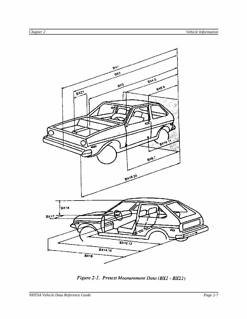
BX1 - BX21 - Pretest Vehicle Measurement Data (millimeters)The fields BX1 through BX21 represent a range of vehicle measurements required for determiningthe extent of damage to the vehicle. The measurements taken before testing are the length of thevehicle and distances between vehicle components:
BX1 - Total Length of Vehicle at CenterlineBX2 - Rear Surface of Vehicle to Front of EngineBX3 - Rear Surface of Vehicle to FirewallBX4 - Rear Surface of Vehicle to Upper Leading Edge of Right DoorBX5 - Rear Surface of Vehicle to Upper Leading Edge of Left DoorBX6 - Rear Surface of Vehicle to Lower Leading Edge of Right DoorBX7 - Rear Surface of Vehicle to Lower Leading Edge of Left DoorBX8 - Rear Surface of Vehicle to Upper Trailing Edge of Right DoorBX9 - Rear Surface of Vehicle to Upper Trailing Edge of Left DoorBX10 - Rear Surface of Vehicle to Lower Trailing Edge of Right DoorBX11 - Rear Surface of Vehicle to Lower Trailing Edge of Left DoorBX12 - Rear Surface of Vehicle to Bottom of A Post of Right SideBX13 - Rear Surface of Vehicle to Bottom of A Post of Left SideBX14 - Rear Surface of Vehicle to Firewall, Right SideBX15 - Rear Surface of Vehicle to Firewall, Left SideBX16 - Rear Surface of Vehicle to Steering ColumnBX17 - Center of Steering Column to A PostBX18 - Center of Steering Column to HeadlinerBX19 - Rear Surface of Vehicle to Right Side of Front BumperBX20 - Rear Surface of Vehicle to Left Side of Front BumperBX21 - Length of Engine Block
Figure 2-1 illustrates these measurements.
Numeric fields, real.
Chapter 2 Vehicle Information
NHTSA Vehicle Data Reference Guide Page 2-5
VEHSPD - Vehicle Speed (kilometers per hour)VEHSPD is the resultant speed of the vehicle immediately before impact.
Numeric field, real.
CRBANG - Crabbed Angle (degrees)CRBANG is the magnitude of the crabbed angle measured clockwise from the longitudinal axis to thevelocity vector of the vehicle. The angle is between 0 degrees and 359 degrees.
The crabbed angle will normally be 0 (forward motion) unless a special test method is employed tointroduce an initial yaw. Figure 2-2 shows an example of CRBANG in which the direction of travelof the vehicle does not correspond to the longitudinal axis.
Numeric field, integer.
PDOF - Principal Direction of Force (degrees)PDOF is the angle (measured clockwise positive) between the vehicle's longitudinal axis and theimpulse vector. The angle is between 0 degrees and 359 degrees.
The principal force is the resultant of forces acting on the vehicle at the point of application. Figure2-3 shows an example of the impulse vector resulting from an impact to a forward-moving vehiclefrom the left side.
Numeric field, integer.
BMPENG - Bumper EngagementBMPENG describes the bumper engagement of vehicle I and vehicle 2. BMPENG applies only tocollisions in which two vehicles moving along the same longitudinal axis collide. A code of DEwould indicate direct engagement of the bumpers.
Coded text, fixed length, 2 characters.
SILENG - Sill EngagementSILENG is the engagement of the side sill (rocker panel area) of vehicle 2 by the bumper of vehicle 1.SILENG applies only to side impacts.
Coded text, fixed length, 2 characters.

Vehicle Information Chapter 2
Page 2-6 NHTSA Vehicle Data Referemce Guide
APLENG - A-Pillar EngagementAPLENG describes the engagement of the A-pillar of a vehicle that has been impacted from the side. APLENG applies only to side impacts.
Coded text, fixed length, 2 characters.
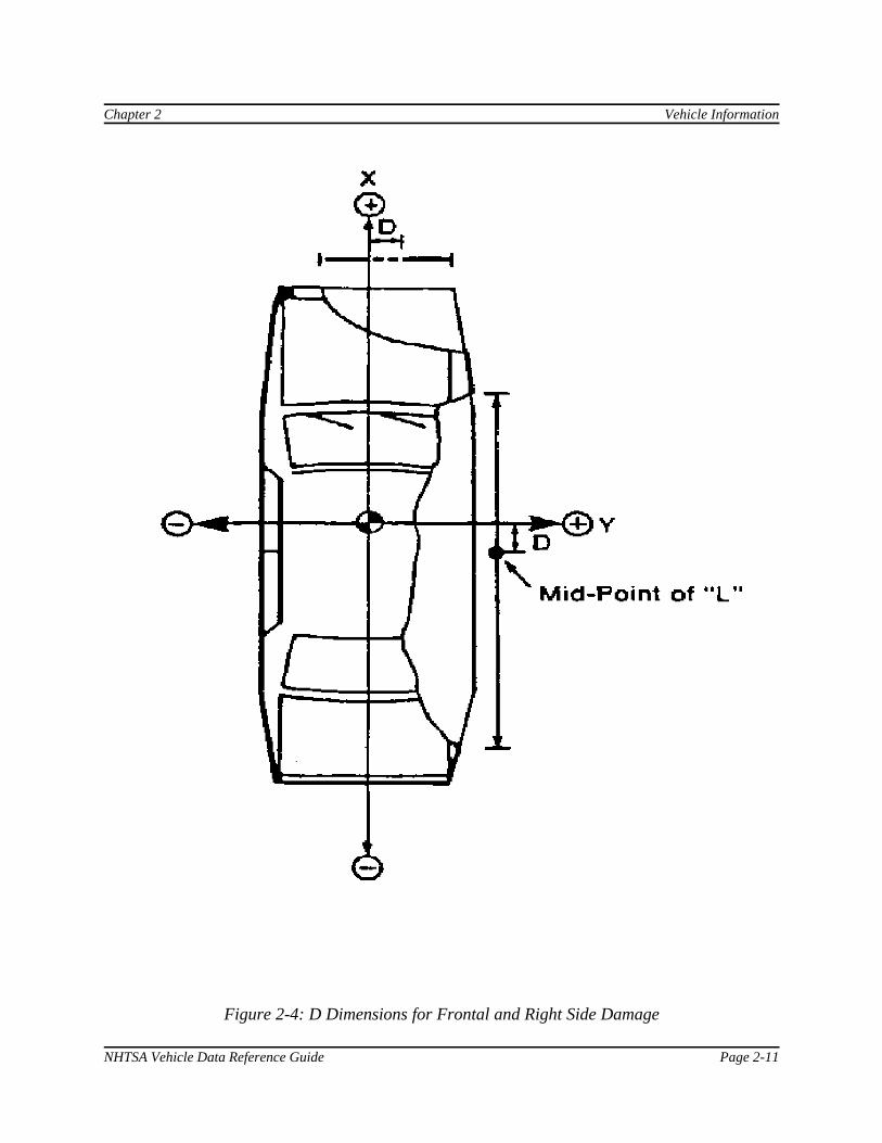
DPD1-DPD6 - Damage Profile Distances (millimeters)Figures 2-4 and 2-5 illustrate the crush profile of the damaged vehicle. The dimensions of the crushare determined by finding the values of L, D, and the DPD's. L is the length of the damaged area; Dis the distance from the midpoint of L to the vehicle center of gravity, measured laterally from the Xaxis for frontal damage and longitudinally from the Y axis for side damage; and DPD (damage profiledistance) specifies the depth of the crush. (L and D are represented elsewhere in the coding asLENCNT and DAMDST.)
The DPDs are a series of points that define the dimensions of the crush. Equally spaced, the DPDsrepresent damage profile distance points from which the depth of crush is measured. The depths aremeasured from the outline that the vehicle would follow were it not damaged to the final crushedposition.
Figure 2-4 portrays the two dimensional coordinate system employed in estimating the crushdimensions. As an illustrative example, in Figure 2-4, a vehicle has sustained frontal and right sidedamage.
To determine D for the right side damage, L, the length of the damage, is measured and divided inhalf, to locate the midpoint of the damage; the distance from the midpoint of L to the lateral, or Y,axis is then measured to determine the value of D. To determine D for the frontal damage, L ismeasured and divided in half-, the distance from the midpoint of L to the longitudinal, or X, axis ismeasured, yielding the value of D.
Figure 2-5 shows DPD dimensions for frontal and right side damage. The DPDs are equally spacedalong the length of L (L is divided into five equal parts if six points are necessary to estimate thedamage; four points are used if the length of the damage is 400 mm or less.)
For side impacts, the six DPD measurements are numbered from the rear to the front. DPD Icorresponds to the beginning of the damage. Unless the damage includes the rear comer of thevehicle, DPD I is 0.0. Unless the damage extends to the front comer, DPD 6 is 0.0. For front and reardamage, the DPD measurements are taken from the vehicle's left to the vehicle's right.
If the orientation of L, D, and DPD is difficult to judge, consult the CDC Column 3 code, whichapplies certain standards in determining the orientation of the damage. The CDC document, alsoknown as 'Collision Deformation Classification,' is contained in Appendix E.
Numeric field, integer.
Chapter 2 Vehicle Information
NHTSA Vehicle Data Reference Guide Page 2-7

Vehicle Information Chapter 2
Page 2-8 NHTSA Vehicle Data Referemce Guide
Figure 2-2. Crabbed Angle (CRBANG)

Chapter 2 Vehicle Information
NHTSA Vehicle Data Reference Guide Page 2-9
Figure 2-3. Principle Direction of Force (PDOF)

Vehicle Information Chapter 2
Page 2-10 NHTSA Vehicle Data Referemce Guide
VDI - Vehicle Damage Index (Collision Deformation Classification)VDI is the vehicle damage index.
SAE Recommended Practice (SAE J224a), 'Collision Deformation Classification' uses this index,composed of seven categories of information, as a basis for uniformly classifying the extent ofdeformation caused in vehicle accidents.
Free text, fixed length, 7 characters.
LENCNT - Total Length of Indentation (millimeters)LENCNT is the length of the total contact damage incurred by the vehicle. Figure 2-6 shows anexample of how the total length of the indentation is the combination of direct and induced damage.
In that example, vehicle 1 impacts vehicle 2. The portion of vehicle 2 that is in direct contact withvehicle 1 represents the direct damage length; while the induced damage is that damage to vehicle 2that results from the impact but that is not in direct contact with vehicle 1.
This definition for the total length of indentation is used except in the following examples:
If a vehicle impacts a vehicle or barrier at 0 degrees (full-frontal impact), the total length ofindentation cannot be greater than the width of the vehicle.
If a narrow object, such as a pole, is impacted by a vehicle and the vehicle 'wraps around' the objectsuch that the total length of indentation is less than the width of the object, then the corrected totallength of indentation will be the width of the object.
Numeric field, integer.
DAMDST - Distance Between Center of Damaged Area and Center of Gravity Axis (millimeters)DAMDST is the distance between the center of the damaged area and the center of gravity axis. Themeasurement is made along the longitudinal axis for side damage and along the lateral axis for frontaldamage. (See Figure 2-4 for possible instances of DAMDST.)
If the center-most point of damage is to the right or front of the center of gravity, the distance ispositive. If the center-most point of damage is to the left or rear of the center of gravity, the distanceis negative. In estimating front or rear damage, assume that the center of gravity lies on thecenterline.
Numeric field, integer.
Chapter 2 Vehicle Information
NHTSA Vehicle Data Reference Guide Page 2-11
Figure 2-4: D Dimensions for Frontal and Right Side Damage

Vehicle Information Chapter 2
Page 2-12 NHTSA Vehicle Data Referemce Guide
Figure 2-5. DPD Dimensions for Frontal and Right Side Damage

Chapter 2 Vehicle Information
NHTSA Vehicle Data Reference Guide Page 2-13
Figure 2-6: Length of Direct Contact Damage (LENCNT)

Vehicle Information Chapter 2
Page 2-14 NHTSA Vehicle Data Referemce Guide
CRHDST - Maximum Crush Distance (millimeters)CRHDST indicates the maximum static crush distance (damage penetration), regardless of itslocation.
Numeric field, integer.
AM - AX21 - Post-test Vehicle Measurement Data (millimeters)The fields AX I through AX21 represent a range of vehicle measurements required for determiningthe extent of damage to the vehicle. The measurements taken after testing involve the length of thevehicle and distances between vehicle components:
AX1 - Total Length of Vehicle at CenterlineAX2 - Rear Surface of Vehicle to Front of EngineAX3 - Rear Surface of Vehicle to FirewallAX4 - Rear Surface of Vehicle to Upper Leading Edge of Right DoorAX5 - Rear Surface of Vehicle to Upper Leading Edge of Left DoorAX6 - Rear Surface of Vehicle to Lower Leading Edge of Right DoorAX7 - Rear Surface of Vehicle to Lower Leading Edge of Left DoorAX8 - Rear Surface of Vehicle to Upper Trailing Edge of Right DoorAX9 - Rear Surface of Vehicle to Upper Trailing Edge of Left DoorAX10 - Rear Surface of Vehicle to Lower Trailing Edge of Right DoorAX11 - Rear Surface of Vehicle to Lower Trailing Edge of Left DoorAX12 - Rear Surface of Vehicle to Bottom of A Post of Right SideAX13 - Rear Surface of Vehicle to Bottom of A Post of Left SideAX14 - Rear Surface of Vehicle to Firewall, Right SideAX15 - Rear Surface of Vehicle to Firewall, Left SideAX16 - Rear Surface of Vehicle to Steering ColumnAX17 - Center of Steering Column to A PostAX18 - Center of Steering Column to HeadlinerAX19 - Rear Surface of Vehicle to Right Side of Front BumperAX20 - Rear Surface of Vehicle to Left Side of Front BumperAX21 - Length of Engine Block
Figure 2-7 illustrates these measurements.
Numeric fields, integer.

Chapter 2 Vehicle Information
NHTSA Vehicle Data Reference Guide Page 2-15
Figure 2-7. Posttest Vehicle Measurement Data (AX1 - AX2)

Vehicle Information Chapter 2
Page 2-16 NHTSA Vehicle Data Referemce Guide
Figure 2-8. Vehicle Orientation on Test Cart (VEHOR)
CARANG - Angle of Moving Test Cart (degrees)CARANG is the magnitude of the angle between the surface of a rollover test cart and the ground. The standard angle specified in FMVSS 208 is 23 degrees.
Numeric field, integer.
VEHOR - Vehicle Orientation on Moving Cart (degrees)VEHOR is the magnitude of the angle of the vehicle orientation in relation to the test cart surface. Ifthe vehicle is positioned sideways on the cart, the magnitude of the angle of orientation is defined as90 degrees, according to FMVSS 208. The angle is between 0 degrees and 90 degrees, as illustratedin Figure 2-8.
Numeric field, integer.
VEHCOM - Vehicle CommentaryVEHCOM is used to describe any special features of the vehicle. The reason for coding any of thecoded fields in this group OTHER or NOT APPLICABLE should be recorded in this field as well. Ifno comments are to be made, enter NO COMMENTS in this field.
Free text, variable length, maximum 70 characters.

NHTSA Vehicle Data Reference Guide Page 3-1
3. BARRIER INFORMATION
The data elements defined below constitute the third test group, Barrier Information. These elementsapply only to a fixed object that doesn't move, such as a bridge rail; a flat angled barrier; a flat barrier;a guard rail; a guard rail terminal; an impact attenuator; a load cell barrier; a luminare; a medianbarrier; a pole; a rollover ramp; or a sign support.
If no barrier is present in a test, section 3, Barrier Information, should be omitted from the datasubmission. The specification file should not include this missing information group by referring to itat all; section 2, Vehicle Information, should be followed directly by section 4, Occupant Information.
Appendix B contains a list of valid codes.
TSTNO - TEST NUMBERTSTNO is a preassigned code (0) which is utilized by the data processing software when loadingASCII format input files into the NHTSA Vehicle database.
Coded text, fixed length, 1 character.
BARRIG - Rigid or Deformable BarrierBARRIG indicates a rigid or deformable barrier.
Coded text, fixed length, 1 character.
BARSHP - Barrier ShapeBARSHP indicates the type of barrier.
Coded text, fixed length, 3 characters.
BARANG - Angle of Fixed Barrier (degrees)BARANG is the magnitude of the angle between the vehicle path and the perpendicular to a barrierthat is fixed and flat. If the vehicle path and the perpendicular are the same, the magnitude of theangle is 0. All other possibilities from 0 to 90 degrees are positive.
Numeric field, integer.

Barrier Information Chapter 3
Page 3-2 NHTSA Vehicle Data Reference Guide
BARDIA - Diameter of Pole Barrier (millimeters)BARDIA is the diameter of a pole barrier.
Numeric field, integer.
BARCOM - Barrier CommentaryBARCOM is further commentary on a particular barrier test procedure. For instance, if the barrier isdeformable, a brief indication of the design and force/deflection characteristics could be indicatedhere. The reason for coding any of the coded fields in this group OTHER or NOT APPLICABLEshould be recorded in this field as well. If no comments, are to be made, enter NO COMMENTS inthis field.
Free text, variable length, maximum 70 characters.

NHTSA Vehicle Data Reference Guide Page 4-1
4. OCCUPANT INFORMATION
The data elements defined below consititute the fourth test group, Occupant Information. Thisinformation group may be omitted from the data submission if no occupant was present for the test. If no occupant information is to be included in the specification file, skip this group and go directly to5, Instrumentation Information.
Appendix B contains a list of valid codes.
TSTNO - TEST NUMBERTSTNO is a preassigned code (0) which is utilized by the data processing software when loadingASCII format input files into the NHTSA Vehicle database.
Coded text, fixed length, 1 character.
VEHNO - Test Vehicle Identification NumberVEHNO is the number that identifies the vehicle containing the test occupant as 1 or 2.
Numeric field, integer.
OCCLOC - Occupant LocationOCCLOC indicates the location of the test occupant in the vehicle. A code of 01 would be enteredfor a left front seat passenger (driver).
Coded text, fixed length, 2 characters.
OCCTYP - Occupant TypeOCCTYP is the type of test occupant, such as the type of dummy or other occupant including acadaver or human volunteer. A code of SD would be used for an HSRI side impact dummy.
Coded text, fixed length, 2 characters.
OCCAGE - Occupant AgeOCCAGE is the age of the nondummy test occupant that applies to a cadaver or human volunteer.
Numeric field, integer..
Occupant Information Chapter 4.
Page 4-2 NHTSA Vehicle Data Reference Guide
OCCSEX - Occupant SexOCCSEX is the sex of the test occupant, applicable to all test occupants except child dummies.
Coded text, fixed length, 1 character.
OCCHT - Occupant Height (millimeters)OCCHT is the height of the nondummy test occupant, measured as the test occupant stands.
Numeric field, integer.
OCCWT - Occupant Weight (kilograms)OCCWT is the weight of the nondummy test occupant.
Numeric field, integer.
MTHCAL - Method of CalibrationMTHCAL indicates which method was used to calibrate the dummy test occupant. A standard Part572 calibration would be coded as P5.
Coded text, fixed length, 2 characters.
DUMSIZ - Dummy Size PercentileDUMSIZ indicates the size of the dummy test occupant, measured either as a standard size percentileor by age classification for child dummies.
Coded text, fixed length, 2 characters.
DUMMAN - Dummy ManufacturerDUMMAN is the manufacturer and the serial number of the dummy occupant. The informationshould be entered as MFG: (manufacturer's name), S/N (dummy serial number).
Free text, variable length, maximum 70 characters.
Chapter 4. Occupant Information
NHTSA Vehicle Data Reference Guide Page 4-3
DUMMOD - Dummy ModificationDUMMOD is the description of the modifications to a prototype dummy test occupant. If nomodifications were made, enter UNMODIFIED.
Free text, variable length, maximum 70 characters.
DUMDSC - Description of the DummyDUMDSC is the description of the calibration and substitution of parts in a dummy test occupant. Ifno comments are to be made, enter NO COMMENTS in this field.
Free text, variable length, maximum 70 characters.
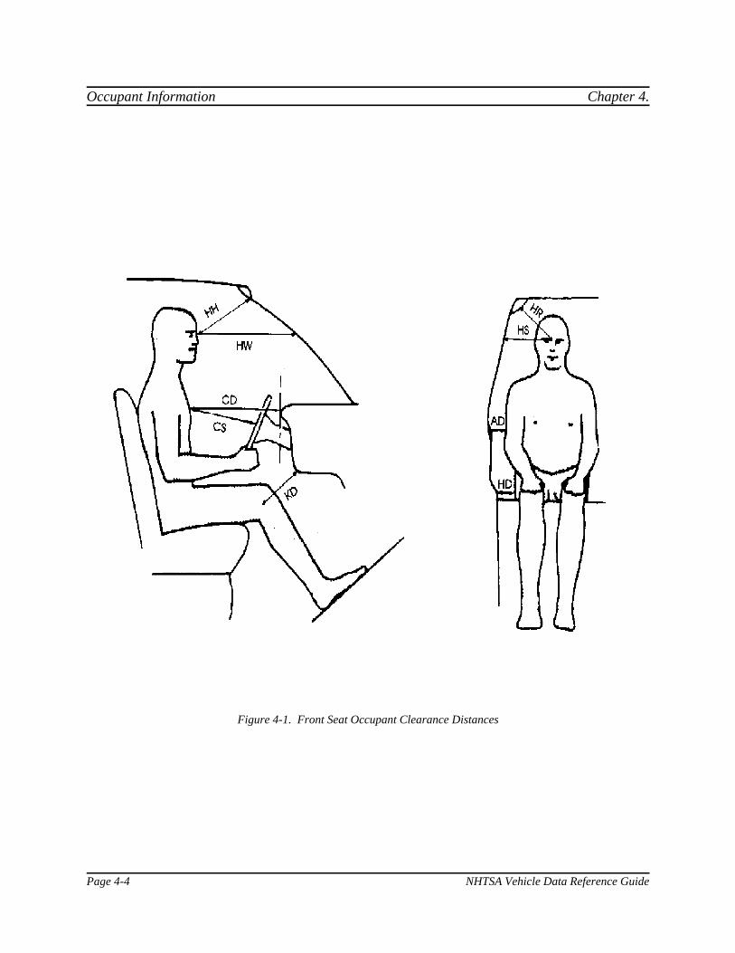
CLEARANCE DISTANCES - Clearance Distances Between Test Occupant and VehicleComponents (millimeters)Clearance distances are the distances between the test occupant and the interior components of thevehicle before the test is conducted. Each dimension is generally defined below and illustrated inFigures 4-1 and 4-2 for front and rear seat test occupants.
<< HH - Head to Windshield Header - Distance from the point where the nose meets theforehead (between the eyes) to the farthest point forward on the header. (Applicable to frontseat occupants only.)
<< HW - Head to Windshield - Horizontal distance from the point where the nose meets theforehead (between the eyes) to the point on the windshield immediately in front of the testoccupant. (Applicable to front seat occupants only.)
<< HR - Head to Side Header - The shortest distance from the point where the nose meets theforehead (between the eyes) to the header (or pillar) immediately to the side of the testoccupant. (Applicable to front and rear seat occupants.)
<< HS - Head to Side Window - Horizontal distance from the point where the nose meets theforehead (between the eyes) to the point on the window (or pillar) immediately to the side ofthe test occupant. (Applicable to front and rear seat occupants.)
<< CD - Chest to Dash - Horizontal distance from the chest of the test occupant (near thesternum) to the dashpanel. (Applicable to front seat occupants only.)
<< CS - Chest to Steering Wheel - Distance from the chest (near the sternum) to the hub of thesteering wheel for a test occupant seated in the driver's position. (Applicable to front seatdriver side occupants only.)
Occupant Information Chapter 4.
Page 4-4 NHTSA Vehicle Data Reference Guide
Figure 4-1. Front Seat Occupant Clearance Distances

Chapter 4. Occupant Information
NHTSA Vehicle Data Reference Guide Page 4-5
Figure 4-2. Rear Seat Occupant Clearance Distances

Occupant Information Chapter 4.
Page 4-6 NHTSA Vehicle Data Reference Guide
CLEARANCE DISTANCES (continued)
<< AD - Arm to Door - Horizontal distance from the midpoint of the upper arm to the door orthe side of the vehicle immediately to the side of the test occupant. (Applicable to front andrear seat occupants.)
< HD - Hip to Door - Horizontal distance from the hip (H-point) to the door or the side of thevehicle immediately to the side of the test occupant. (Applicable to front and rear seatoccupants.)
< KD - Knees to Dash -The shortest distance from the center of the knee pivot bolt's outersurface to the lower dash panel immediately in front of the test occupant. (Applicable to frontseat occupants only.)
<< HB - Head to Seatback - The horizontal distance from the point where the nose meets theforehead (between the eyes) to the seatback immediately in front of the test occupant.(Applicable to rear seat occupant only.)
<< NB - Neck to Seatback - Horizontal distance from the neck to the seatback immediately infront of the test occupant. (Applicable to rear seat occupants only.)
<< CB - Chest to Seatback - Horizontal distance from the chest (near the sternum) to theseatback immediately in front of the test occupant. (Applicable to rear seat occupants only.)
<< KB - Knee to Seatback - Horizontal distance from the center of the knee pivot bolt's outersurface to the back of the front seat. (Applicable to rear seat occupants only.)
Numeric field, integer.
SEPOSN - Seat PositionSEPOSN is the position of the seat at the initiation of the test.
Coded text, fixed length, 2 characters.
CNTRH1 - First Contact Region for HeadCNTRH I is the first point of contact for the test occupant's head.
Coded text, fixed length, 2 characters.

Chapter 4. Occupant Information
NHTSA Vehicle Data Reference Guide Page 4-7
CNTRH2 - Second Contact Region for HeadCNTRH2 is the second point of contact for the test occupant's head.
Coded text, fixed length, 2 characters.
CNTRC1 - First Contact Region for Chest or AbdomenCNTRC I is the first point of contact for the test occupant's chest or abdomen.
Coded text, fixed length, 2 characters.
CNTRC2 - Second Contact Region for Chest or AbdomenCNTRC2 is the second point of contact for the test occupant's chest or abdomen.
Coded text, fixed length, 2 characters.
CNTRL1 - First Contact Region for LegsCNTRL1 is the first point of contact for the test occupant's legs.
Coded text, fixed length, 2 characters.
CNTRL2 - Second Contact Region for LegsCNTRL2 is the second point of contact for the test occupant's legs.
Coded text, fixed length, 2 characters.
HIC - Head Injury CriterionHIC is the computed value of the head injury criterion, based on the resultant acceleration pulse forthe head center of gravity. In computing this value, the contractor shall use the HIC algorithmsupplied by NHTSA.
Numeric, integer.
T1 - Lower Boundary of HIC Time Interval (milliseconds)TI is the lower boundary of the time interval over which the HIC was computed.
Numeric, real.

Occupant Information Chapter 4.
Page 4-8 NHTSA Vehicle Data Reference Guide
T2 - Upper Boundary of HIC Time Interval (milliseconds)T2 is the upper boundary of the time interval over which the HIC was computed.
Numeric, real.
CLIP3M - Thorax Region Peak Acceleration Measurement (g’s)CLIP3M is the maximum 3-millisecond 'clip' value of the chest resultant acceleration, in g's, afterfiltering with a Class 180 filter (300 Hz Butterworth, low pass, refer to SAE Standard J211 B). Incomputing the CLIP3M measurement, the contractor shall use the 'clip' algorithm supplied byNHTSA.
Numeric, real.
LFEM - Left Femur Peak Load Measurement (newtons)LFEM indicates the maximum compression load for the left femur. Listed as a negative number.
Numeric, integer.
RFEM - Right Femur Peak Load Measurement (newtons)RFEM indicates the maximum compression load for the right femur. Listed as a negative number.
Numeric, integer.
CSI - Chest Severity IndexCSI indicates the computed value of the chest severity index.
Numeric, integer.
LBELT - Lap Belt Peak Load Measurement (newtons)LBELT indicates the maximum tension load on the lap belt.
Numeric, integer.
Chapter 4. Occupant Information
NHTSA Vehicle Data Reference Guide Page 4-9
SBELT - Shoulder Belt Peak Load Measurement (newtons)SBELT indicates the maximum tension load on the shoulder belt.
Numeric, integer.
TTI - Thoracic Trauma IndexTTI is the thoracic trauma index value. For a dummy, TTI(d) is computed from the maximum rib andlower spine peak accelerations. In computing this value, the contractor shall use the TTI algorithmsupplied by NHTSA.
Numeric field, real.
PELVG - Pelvic G’sPELVG, the pelvis injury criterion, is the peak lateral acceleration on the pelvis. It is obtained afterfiltering with the FIR100 filtering software supplied by NHTSA.
Numeric field, real.
OCCCOM - Occupant CommentaryOCCCOM is used to describe any distinguishing features of the test occupant. The reason for codingany of the coded fields in this group OTHER or NOT APPLICABLE should be recorded in this fieldas well. If no comments are to be made, enter NO COMMENTS in this field.
Free text, variable length, 70 characters.

Occupant Information Chapter 4.
Page 4-10 NHTSA Vehicle Data Reference Guide
[This page intentionally left blank]

NHTSA Vehicle Data Reference Guide Page 5-1
5. OCCUPANT RESTRAINTS INFORMATION
The data elements defined below comprise the fifth data group, Occupant Restraints Information. Appendix B contains a list of valid codes.
Restraint information is required for each test occupant. For unrestrained occupants, RESTYP =NON. Belts should be coded only if they were used in the test. Inflatable restraints should be codedwhether the test resulted in deployment or not. If an occupant is protected by three restraints, e.g. a 3point belt, and front and side air bags, three restraint records should be generated for that occupant.
TSTNO - TEST NUMBERTSTNO is a preassigned code (0) which is utilized by the data processing software when loadingASCII format input files into the NHTSA Vehicle database.
Coded text, fixed length, 1 character.
VEHNO - Test Vehicle Identification Number VEHNO is the number that identifies the vehicle containing the test occupant as 1 (striking vehicle)or 2 (target vehicle).
Numeric field, integer.
OCCLOC - Occupant LocationOCCLOC indicates the location of the test occupant within the vehicle. A code of 01 would beentered for a left front seat driver.
Coded text, fixed length, 2 characters.
RSTNO - Restraint Number RSTNO is the sequential number assigned to each restraint system in use for a given occupant at thetime of the test. RSTNO = 1 for the first restraint listed for each occupant.
Numeric field, integer.
Occupant Restraints Information Chapter 5
Page 5-2 NHTSA Vehicle Data Reference Guide
RSTTYP - Restraint Type RSTTYP is the type of restraint system in use at a given occupant location. Inflatable restraints areconsidered to be “in use” for occupied seating positions. [RSTTYP is the type of restraint systemcurrently coded in the OCCUPANT section as RESTR1 and RESTR2, i.e. ABG, 3PT, 3PS, ITS(for BMW’s inflatable tubular structure), etc.]
Coded text, fixed length, 3 characters.
RSTMNT - Restraint MountRSTMNT indicates the interior component(s) to which the restraint is mounted or from which itoriginates. For a driver frontal air bag, RSTMNT is the steering wheel hub (SH). Side air bags/airbelts could be mounted in the seatback (SB), door (DR), or side header (HS).
DEPLOY - Inflator/Belt Pretrensioner DeploymentDEPLOY describes the deployment performance of inflatable restraints or the firing of the beltpretensioner during the test.
Coded text, fixed length, 2 characters.
RSTCOM - Restraint CommentaryRSTCOM is used to describe any distinguishing features of the restraint system. If OTHER is usedto code the any of the restraint system fields, descriptive information may be added here. If nocomments are to be made, enter NO COMMENTS here.
Free text, variable length, miximum 70 characters.

NHTSA Vehicle Data Reference Guide Page 6-1
6. INSTRUMENTATION INFORMATION
The data elements defined below constitute the sixth test group, Instrumentation Information. Appendix B contains a list of valid codes.
Approximately twenty milliseconds of data prior to time zero should come with all measurement data;data shall meet the class 1000 specifications of the SAE J211 recommendation; and all data should betruncated at a common time value to avoid extending the pulse well past the period of significantactivity.
The minimum sample rate shall be 10000 Hz. A sample rate should be chosen such that the DELTvalue does not have to be rounded off.
TSTNO - TEST NUMBERTSTNO is a preassigned code (0) which is utilized by the data processing software when loadingASCII format input files into the NHTSA Vehicle database.
Coded text, fixed length, 1 character.
VEHNO - Test Vehicle Identification NumberVEHNO is the number that identifies the vehicle containing the sensor as 1 or 2. VEHNO should becoded 0 if the sensor is attached to a barrier.
Numeric field, integer.
CURNO - Curve NumberCURNO is the sequential number (1,2,3 ... ) assigned to a specific sensor and data curve.
Numeric field, integer.
SENTYP - Sensor TypeSENTYP indicates the type of sensor used for collecting the measurements at the time of the test,such as AC for accelerometer.
Coded text, fixed length, 2 characters.

Instrumentation Information Chapter 6
Page 6-2 NHTSA Vehicle Data Reference Guide
SENLOC - Sensor LocationSENLOC indicates the location of the test occupant or corresponding occupant restraint to which thesensor is attached. SENLOC should correspond to a previously entered value of OCCLOC.
Coded text, fixed length, 2 characters.
SENATT - Sensor AttachmentSENATT indicates where the sensor is attached. For example, the code APLR would be entered foran attachment on the right A-pillar.
Coded text, fixed length, 4 characters.
AXIS - Axis Direction of the SensorAXIS is the axis direction for sensors measuring vector quantities. The global coordinate systems arevehicle fixed; the local systems are local within the vehicle global system. With respect to the vehiclelongitudinal axis, X is positive forward, Y is positive right, (toward the passenger’s door) and Z ispositive down. These can differ depending on the component. For example, with the steeringassembly, positive X is down the column axis and Y is positive right (toward the passenger’s door).
AXIS is always applicable when the measurement is a vector quantitiy (acceleration, force, velocity,and so forth). Figure 6-1 illustrates the body- and vehicle-based coordinate system. Note that thehead accelerometer array is a local coordinate system. The distance, d, is the length of the armbetween HD90 and HD9Y, measured along the Y arm. The reporting of this value of d is describedin the INSCOM field. The length of the X arm and the Z arm are reported in the same manner. Allsignals from anatomical sensors, (HDCG, etc.), are local coordinate systems.
Included in Appendix D are the required sign conventions for various possible measurements. Onlythese sign conventions are acceptable.
Coded text, fixed length, 2 characters.
UNITS - Data Measurement UnitsUNITS indicates the units used to measure the signal of the sensor data. (Refer to Table 1-1 for theonly acceptable units.)
Coded text, fixed length, 3 characters.

Chapter 6. Instrumentation Information
NHTSA Vehicle Data Reference Guide Page 6-3
Figure 6-1: Vehicle, Body, and Head 9-Accelerometer Array

Instrumentation Information Chapter 6
Page 6-4 NHTSA Vehicle Data Reference Guide
PREFIL - Prefilter FrequencyPREFIL is the corner (or cutoff) frequency in Hz of a low-pass filter used for digitizing data. Thisfrequency is defined as where filter gain equals 70 percent (-3dB).
Numeric field, integer.
INSMAN - Manufacturer of the InstrumentINSMAN describes the manufacturer of the instrument. The model and serial number should also beincluded. The format for this field should be: MFG: manufacturer name, S/N: serial number.
Free text, variable length, maximum 70 characters.
CALDAT - Calibration Date (DD/MMM/YYYY)CALDAT is the most recent calibration date of the instrument.
Date text, fixed length, 11 characters.
INSRAT - Instrument RatingINSRAT represents the maximum value that can be accurately measured by the recording system fora channel. INSRAT should be in the same units as the data channel, except in the case of barrier loadcell data where the units of INSRAT are kilonewtons.
Numeric field, integer.
CHLMAX - Channel Maximum RatingCHLMAX represents the full-scale value of the data based upon the actual test setup, including signalconditioning, as a percentage of INSRAT.
Numeric field, integer.
INIVEL - Initial Velocity (kilometers per hour)INIVEL is the initial (time zero) velocity of the sensor along its axis and applies only to linearaccelerometers. If the sensor is a load cell attached to a barrier, the entry for this field should be zero(0.0).
Numeric field, real.
Chapter 6. Instrumentation Information
NHTSA Vehicle Data Reference Guide Page 6-5
NFP - Number of First PointNFP represents the index number of the first point in the data array (less than or equal to 0). Timezero always has an index number of 0. If no data exists prior to time zero, NFP is equal to 0; if 20data points exist prior to time zero, NFP is equal to -20. There may never be more than 10,000points before time zero.
Numeric field, integer.
NLP - Number of Last PointNLP represents the index number of the last point in the data array. If 1,000 points were digitized,and NFP is equal to -100, then NLP is equal to 899. NLP can never be greater than 99,999.
Numeric field, integer.
DELT - Time Increment (microseconds)DELT is the time increment in microseconds between each data point. DELT is assumed to beconstant for all data points for a given sensor (uniform sampling frequency).
Numeric field, integer.
DASTAT - Data StatusDASTAT indicates the status of the data as it appears in the data submission. This field is used toindicate a signal which is invalid (code MN for meaningless), or which becomes questionable orinvalid part of the way through a signal (code CF and explained in INSCOM). If a signal iscomputed, DASTAT is CM. An example of a computed signal would be the resultant acceleration orthe rotational acceleration of the head measured with a nine linear accelerometer array.
Coded text, fixed length, 2 characters.
CHSTAT - Channel StatusCHSTAT indicates whether the data channel is primary or redundant. If, for example, the dummy isinstrumented with a backup triaxial accelerometer in the head, the redundant channels should belabeled R. The occupant’s HIC value would be calculated using the primary head channels, labeled P.
Coded text, fixed length, 1 character.

Instrumentation Information Chapter 6
Page 6-6 NHTSA Vehicle Data Reference Guide
INSCOM - Instrumentation CommentaryINSCOM is any further commentary on the instrumentation data, including any unusual conditionsaffecting the data or a reference to a document that describes problems with a particular curve. Thereasons for coding any of the coded fields in this group OTHER or NOT APPLICABLE should berecorded in this field as well. If no comments are to be made, enter NO COMMENTS.
For Head 9 array accelerometers, INSCOM contains dimensions that precisely locate the giveninstrument. The HD90, X-axis accelerometer, will locate the center of the Head 9 array relative tothe head CG; then the entry in INSCOM for HD90 would read: CG: X: 33MM, Y: 2.5MM, Z: -5.0MM.
The X-axis of HD9Y, HD9X, and HD9Z will contain the distance, d, shown in Figure 6-1, which isthe length of the arm. Units must be shown. For example, if the Y arm is 110 mm long, then theentry in INSCOM for HD9Y, X direction would read: Y-ARM: 110 MM.
Free text, variable length, maximum 70 characters.

NHTSA Vehicle Data Reference Guide Page A-1
APPENDIX A:MAGNETIC MEDIA FORMAT
Each data submission consists of two types of data: descriptive specification data defined in theprevious sections of this Guide, and the measurement data digitized from the test instrumentationsignal traces. Several disks may be required to record the specification and measurement files fora test submitted on diskette.
USING THE ENTREEW PROGRAM TO CREATE SPECIFICATION FILES
NHTSA has developed the data entry program, ENTREEW, in order to facilitate preparation ofthe specification data defined in the previous sections of this Guide. A diskette containing theENTREEW program, Version 4.0, is included in the front of the Guide. Because ENTREEWcontains built-in, on-line checkers for data validation, it is highly recommended that specificationdata be generated using the ENTREEW program.
Equipment Requirements for ENTREEW
ENTREEW is a Windows-based application which has the following minimum requirements:
< IBM PC or compatible with 80386 or better processor.
< 10 Megabytes of disk space.
< Microsoft Windows 3.1 or later.
< 8 Megabytes of memory.
ENTREEW should also run properly under Microsoft Windows 95, Windows NT 3.51 orWindows NT 4.0.
ENTREEW Conversion Utilities
The ENTREEW program output file is in NHTSA’s own binary format (file extension .ENT). The included EWCONV utility supports the export of binary .ENT files to the ASCII .EV4format .EV4 files, which is the accepted data format specified under SAE J211. EWCONV alsosupports the import of .EV4 ASCII data files into the binary .ENT format for editing usingENTREEW.
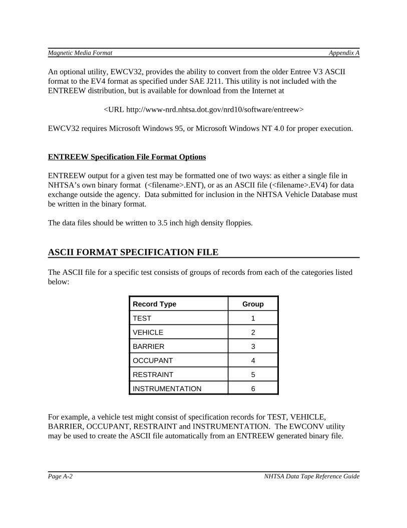
Magnetic Media Format Appendix A
Page A-2 NHTSA Data Tape Reference Guide
An optional utility, EWCV32, provides the ability to convert from the older Entree V3 ASCIIformat to the EV4 format as specified under SAE J211. This utility is not included with theENTREEW distribution, but is available for download from the Internet at
<URL http://www-nrd.nhtsa.dot.gov/nrd10/software/entreew>
EWCV32 requires Microsoft Windows 95, or Microsoft Windows NT 4.0 for proper execution.
ENTREEW Specification File Format Options
ENTREEW output for a given test may be formatted one of two ways: as either a single file inNHTSA’s own binary format (<filename>.ENT), or as an ASCII file (<filename>.EV4) for dataexchange outside the agency. Data submitted for inclusion in the NHTSA Vehicle Database mustbe written in the binary format.
The data files should be written to 3.5 inch high density floppies.
ASCII FORMAT SPECIFICATION FILE
The ASCII file for a specific test consists of groups of records from each of the categories listedbelow:
Record Type Group
TEST 1
VEHICLE 2
BARRIER 3
OCCUPANT 4
RESTRAINT 5
INSTRUMENTATION 6
For example, a vehicle test might consist of specification records for TEST, VEHICLE,BARRIER, OCCUPANT, RESTRAINT and INSTRUMENTATION. The EWCONV utilitymay be used to create the ASCII file automatically from an ENTREEW generated binary file.
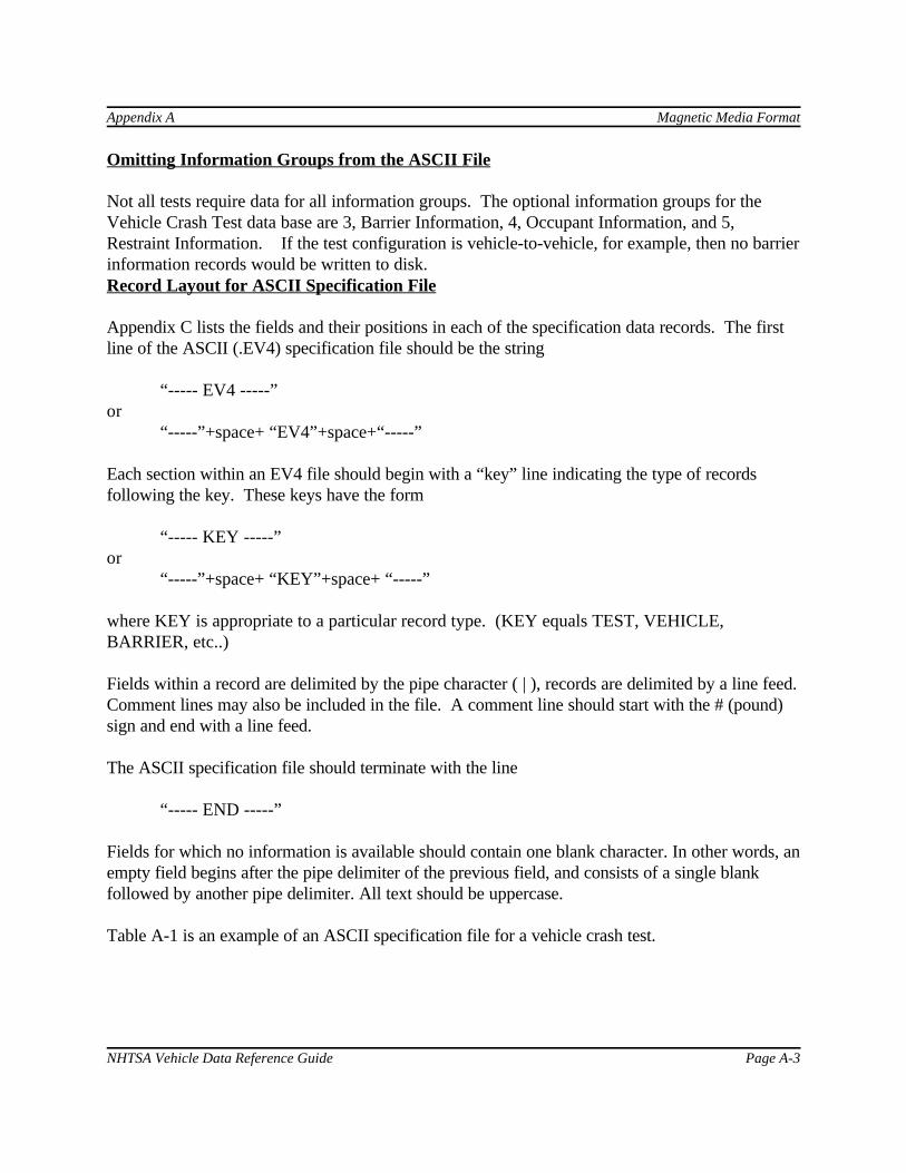
Appendix A Magnetic Media Format
NHTSA Vehicle Data Reference Guide Page A-3
Omitting Information Groups from the ASCII File
Not all tests require data for all information groups. The optional information groups for theVehicle Crash Test data base are 3, Barrier Information, 4, Occupant Information, and 5,Restraint Information. If the test configuration is vehicle-to-vehicle, for example, then no barrierinformation records would be written to disk.Record Layout for ASCII Specification File
Appendix C lists the fields and their positions in each of the specification data records. The firstline of the ASCII (.EV4) specification file should be the string
“----- EV4 -----”or
“-----”+space+ “EV4”+space+“-----”
Each section within an EV4 file should begin with a “key” line indicating the type of recordsfollowing the key. These keys have the form
“----- KEY -----”or
“-----”+space+ “KEY”+space+ “-----”
where KEY is appropriate to a particular record type. (KEY equals TEST, VEHICLE,BARRIER, etc..)
Fields within a record are delimited by the pipe character ( | ), records are delimited by a line feed. Comment lines may also be included in the file. A comment line should start with the # (pound)sign and end with a line feed.
The ASCII specification file should terminate with the line
“----- END -----”
Fields for which no information is available should contain one blank character. In other words, anempty field begins after the pipe delimiter of the previous field, and consists of a single blankfollowed by another pipe delimiter. All text should be uppercase. Table A-1 is an example of an ASCII specification file for a vehicle crash test.

Magnetic Media Format Appendix A
Page A-4 NHTSA Data Tape Reference Guide
LAYOUT FOR MEASUREMENT DATA ON DISK
Each subsequent file after the specification data files contains unfiltered, digitized data collectedfrom the sensors used in the tests. The order of the measurement files corresponds to the order ofthe instrumentation records in the instrumentation group specification records. The measurementfiles are made up of ASCII records of 1 data point each, delimited by a line feed character (ASCIIdecimal 10, hexadecimal \x0a, octal \012). The point specification will allow for any floatingpoint format, but the preferred format is the C format %12.5E. Thus, each record will be 12characters long, e.g. +1.23400E-01. The maximum number of points for one channel is 110,000. There cannot be more than 10,000 data points prior to time zero, nor more than 99,999 after timezero.
The name of the ASCII measurement data files should be the same given to the specification filedescribed above (ENTREEW binary file with extension .ENT or ASCII file with extension .EV4). The file extension should be the curve number of the curve contained in the file, and shouldcorrespond to the curve number in the instrumentation record in the instrumentation specificationgroup. There should be no leading zeros in the file extensions.
If the specification file is named TSTABC.ENT (binary) or TSTABC.EV4 (ASCII), and there are35 measurement (curve) files, the curve files should be named TSTABC.1 through TSTABC.35.
Right: TSTABC.1 TSTABC.12 TSTABC.101
Wrong: TSTABC.T0 TSTABC.012 TSTABCDAT
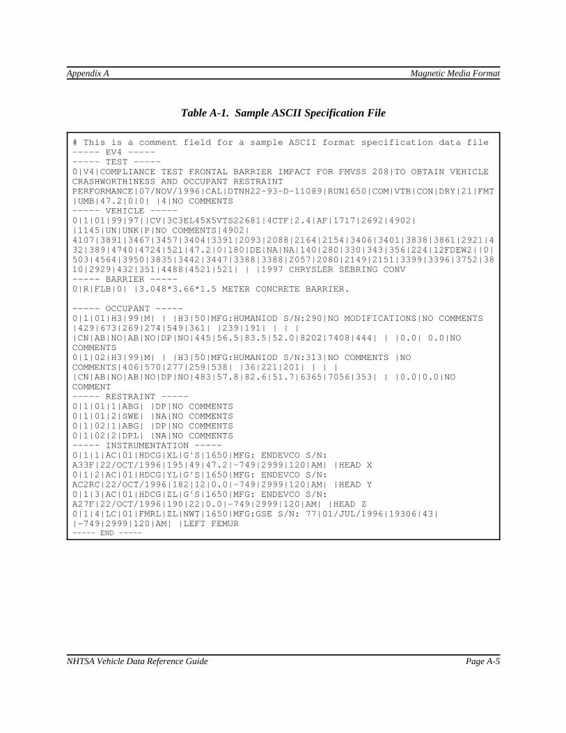
Appendix A Magnetic Media Format
NHTSA Vehicle Data Reference Guide Page A-5
Table A-1. Sample ASCII Specification File
# This is a comment field for a sample ASCII format specification data file----- EV4 ---------- TEST -----0|V4|COMPLIANCE TEST FRONTAL BARRIER IMPACT FOR FMVSS 208|TO OBTAIN VEHICLECRASHWORTHINESS AND OCCUPANT RESTRAINTPERFORMANCE|07/NOV/1996|CAL|DTNH22-93-D-11089|RUN1650|COM|VTB|CON|DRY|21|FMT|UMB|47.2|0|0| |4|NO COMMENTS----- VEHICLE -----0|1|01|99|97||CV|3C3EL45X5VTS22681|4CTF|2.4|AF|1717|2692|4902||1145|UN|UNK|P|NO COMMENTS|4902|4107|3891|3467|3457|3404|3391|2093|2088|2164|2154|3406|3401|3838|3861|2921|432|389|4740|4724|521|47.2|0|180|DE|NA|NA|140|280|330|343|356|224|12FDEW2||0|503|4564|3950|3835|3442|3447|3388|3388|2057|2080|2149|2151|3399|3396|3752|3810|2929|432|351|4488|4521|521| | |1997 CHRYSLER SEBRING CONV----- BARRIER -----0|R|FLB|0| |3.048*3.66*1.5 METER CONCRETE BARRIER. ----- OCCUPANT -----0|1|01|H3|99|M| | |H3|50|MFG:HUMANIOD S/N:290|NO MODIFICATIONS|NO COMMENTS|429|673|269|274|549|361| |239|191| | | ||CN|AB|NO|AB|NO|DP|NO|445|56.5|83.5|52.0|8202|7408|444| | |0.0| 0.0|NOCOMMENTS0|1|02|H3|99|M| | |H3|50|MFG:HUMANIOD S/N:313|NO COMMENTS |NOCOMMENTS|406|570|277|259|538| |36|221|201| | | ||CN|AB|NO|AB|NO|DP|NO|483|57.8|82.6|51.7|6365|7056|353| | |0.0|0.0|NOCOMMENT----- RESTRAINT -----0|1|01|1|ABG| |DP|NO COMMENTS0|1|01|2|SWE| |NA|NO COMMENTS0|1|02|1|ABG| |DP|NO COMMENTS0|1|02|2|DPL| |NA|NO COMMENTS----- INSTRUMENTATION -----0|1|1|AC|01|HDCG|XL|G'S|1650|MFG: ENDEVCO S/N:A33F|22/OCT/1996|195|49|47.2|-749|2999|120|AM| |HEAD X0|1|2|AC|01|HDCG|YL|G'S|1650|MFG: ENDEVCO S/N:AC2RC|22/OCT/1996|182|12|0.0|-749|2999|120|AM| |HEAD Y0|1|3|AC|01|HDCG|ZL|G'S|1650|MFG: ENDEVCO S/N:A27F|22/OCT/1996|190|22|0.0|-749|2999|120|AM| |HEAD Z0|1|4|LC|01|FMRL|ZL|NWT|1650|MFG:GSE S/N: 77|01/JUL/1996|19306|43||-749|2999|120|AM| |LEFT FEMUR----- END -----

Magnetic Media Format Appendix A
Page A-6 NHTSA Data Tape Reference Guide
[this page intentionally left blank]

Codes Appendix B
Page B-30 NHTSA Vehicle Data Reference Guide
MODEL (continued)
CODE DESCRIPTION COMMENT
< WAYNE (make code 66)01 CONVENTIONAL02 FORWARD CONTROL99 OTHER
< WINNEBAGO (make code 60)01 TREKKER99 OTHER
< YUGO (make code 24)01 GV99 OTHER
< OTHER (make code 99)99 OTHER
MODIND
CODE DESCRIPTION COMMENT
M MODIFIED VEHICLE STRUCTURAL AND/OR INTERIORMODIFICATIONS
P PRODUCTION VEHICLE UNMODIFIEDR RESEARCH VEHICLE IMPACTOR OR RSVU UNKNOWN
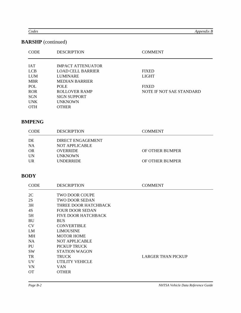
Appendix B Codes
NHTSA Vehicle Data Reference Guide Page B-31
MTHCAL
CODE DESCRIPTION COMMENT
H3 HYBRID IIIHS HSRINA NOT APPLICABLE OCCUPANT NOT A DUMMYNO NONE NO CALIBRATION P5 PART 572UN UNKNOWNOT OTHER
OCCLOC
CODE DESCRIPTION COMMENT
01 LEFT FRONT SEAT02 RIGHT FRONT SEAT03 RIGHT REAR SEAT04 LEFT REAR SEAT05 CENTER FRONT SEAT06 CENTER REAR SEAT07 LEFT THIRD SEAT STATION WAGON/VAN08 CENTER THIRD SEAT STATION WAGON/VAN09 RIGHT THIRD SEAT STATION WAGON/VANOT OTHER OR OUT OF POSITION
OCCSEX
CODE DESCRIPTION COMMENT
F FEMALEM MALEN NOT APPLICABLE OCCUPANT NOT AN ADULT
DUMMYU UNKNOWN
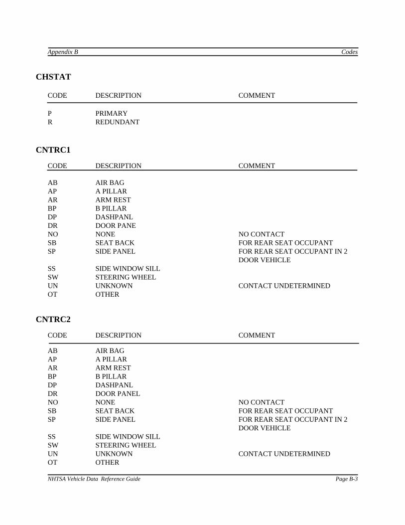
Codes Appendix B
Page B-32 NHTSA Vehicle Data Reference Guide
OCCTYP
CODE DESCRIPTION COMMENT
AO APR OMNIDIRECTIONAL DUMMY APROD
AS APR SIDE IMPACT DUMMY APRSIDBS BIO-SID DUMMYCD CADAVER CADAVRCH CHILD DUMMY CHLDDMES EURO-SID DUMMYH3 HYBRID HI DUMMY HYB3DMHP HUMANOID PEDESTRIAN DUMMY HMNPEDP5 PART 572 DUMMY P572DMSD HSRI SIDE IMPACT DUMMY SIDTR TRRL DUMMY TRRLDMOT OTHER OTHER
RECTYP
CODE DESCRIPTION COMMENT
DIG DIGITAL TAPE RECORDERFMM FM MULTIPLEXOR TAPE RECORDERFMT FM TAPE RECORDEROSC OSCILLOGRAPHUNK UNKNOWNOTH OTHER
RSTMNT
CODE DESCRIPTION COMMENT
AP A PILLARBI BELT - INTEGRATED SEAT MOUNTBC BELT - CONVENTIONAL MOUNTBD BELT - DOOR MOUNTBP B PILLARCP C PILLARAR ARM RESTDR DOOR PANELHR HEAD REST

Appendix B Codes
NHTSA Vehicle Data Reference Guide Page B-33
RSTMNT (continued)
CODE DESCRIPTION COMMENT
HS HEADER - SIDEHW HEADER - WINDSHIELDDM DASH PANEL - MIDDT DASH PANEL - TOPDP DASH PANEL - UNSPECIFIEDOT OTHERNA NOT APPLICABLESB SEAT BACKSP SIDE PANELSS SIDE WINDOW SILLSW STEERING WHEEL
RSTTYP
CODE DESCRIPTION COMMENT
3PT 3 POINT BELT LAP AND SHOULDERABG AIR BAGABT AIR BELTAPP APR PADDINGCHD CHILD RESTRAINTDPL DASHPANELFHP FBRGL. HNCB. PADDING FIBERGLASS HONEYCOMBKNE KNEE RESTRAINT NOTE IF NOT PROVIDED BY MANUFACTURERLAP LAP BELT NO SHOULDER BELTMCP MINICARS PADDINGNON NONE UNRESTRAINEDPAD PADDING NOT APR,MINICARS,OR FIBERGLASS
HONEYCOMBPS2 PASSIVE 2 POINT BELTPS3 PASSIVE 3 POINT BELTRIG RIGID WALLSBK SEAT BACK FOR REAR SEAT OCCUPANTSCE STR. COLUMN - EA ENERGY ABSORBINGSCN STR. COLUMN - NO EA NOT ENERGY ABSORBINGSWE STR. WHEEL - EA ENERGY ABSORBINGSWN STR. WHEEL - NO EA NOT ENERGY ABSORBINGUNK UNKNOWNOTH OTHER

Codes Appendix B
Page B-34 NHTSA Vehicle Data Reference Guide
SENATT
CODE DESCRIPTION COMMENT
ABDI ABDOMEN CONTACT SWITCH I OBLIQUE-ANTERIORABD2 ABDOMEN CONTACT SWITCH 2 LATERALABD3 ABDOMEN CONTACT SWITCH 3 OBLIQUE-POSTERIORABDO ABDOMENABGD AIR BAG DIAGNOSTIC CIRCUITABGL AIR BAG LAMPABGM AIR BAG MANIFOLDABSF AIR BAG SAFING CIRCUITABSQ AIR BAG SQUIB CIRCUITABTF AIR BAG TRIP-SWITCH - FIREWALLABTK AIR BAG TRIP-SWITCH - KNEEABTL AIR BAG TRIP-SWITCH - LEFTABTM AIR BELT MANIFOLDABTR AIR BAG TRIP-SWITCH - RIGHTABTS AIR BAG TRIP-SWITCH - ST. COL.ANKL ANKLE-LEFTANKR ANKLE - RIGHTAPLL A PILLAR - LEFTAPLR A PILLAR - RIGHTBAFF BARRIER FRONT FACINGBMPF BUMPER - FRONTBMPR BUMPER - REARBPLL B PILLAR - LEFTBPLR B PILLAR - RIGHTBRCG BUMPER RIGHT CGBRCL BRAKE CALIPER - LEFTBRCR BRAKE CALIPER - RIGHTCHST CHEST THORAX OR SPINE IN 208 COMPLIANCECPLL C PILLAR - LEFTCPLR C PILLAR - RIGHTCRBV CEREBROVASCULAR SYSTEMCRDV CARDIOVASCULAR SYSTEMDPLC DASHPANEL-CENTERDPLL DASHPANEL-LEFTDPLR DASHPANEL - RIGHTDRLF DOOR - LEFT FRONT DRLR DOOR-LEFTREARDRRF DOOR - RIGHT FRONTDRRR DOOR - RIGHT REARDSLF SILL - LEFT FRONT

Appendix B Codes
NHTSA Vehicle Data Reference Guide Page B-35
SENATT (continued)
CODE DESCRIPTION COMMENT
DSLR SILL - LEFT REARDSRF SILL - RIGHT FRONTDSRR SILL - RIGHT REARENGN ENGINEFFNL FENDER FRONT LEFTFFNR FENDER FRONT RIGHTFLLF FLOORPAN - LEFT FRONTFLLR FLOORPAN - LEFT REARFLRF FLOORPAN - RIGHT FRONTFLRR FLOORPAN - RIGHT REARFLTU FLOORPAN TUNNELFMRL FEMUR - LEFTFMRR FEMUR - RIGHTFOTL FOOT - LEFTFOTR FOOT - RIGHTFRCF FRAME CROSSMEMBER - FRONTFRCR FRAME CROSSMEMBER - REARFRRF FRAME RAIL - FRONTFRRR FRAME RAIL - REARFRSL FRAME SIDE RAIL - LEFTFRSR FRAME SIDE RAIL - RIGHTFWLL FIREWALLHD90 HEAD 9 ARRAY - CENTERHD9X HEAD 9 ARRAY - X ARM FORMERLY HD92, Y AND Z AXES ONLYHD9Y HEAD 9 ARRAY - Y ARM FORMERLY HD9 1, X AND Z AXES ONLYHD9Z HEAD 9 ARRAY - Z ARM FORMERLY HD93, X AND Y AXES ONLYHDCG HEAD CGHDOT HEAD OTHER USE FOR OTHER THAN 9 ACCEL. ARRAY
OR CGHDRL HEADER - LEFTHDRR HEADER - RIGHTHLCR HOOD LATCH CROSSMEMBERKNEL KNEE - LEFTKNER KNEE - RIGHT LCA0 LOAD CELL A10LCAl LOAD CELL A1LCA2 LOAD CELL A2LCA3 LOAD CELL A3LCA4 LOAD CELL A4LCA5 LOAD CELL A5
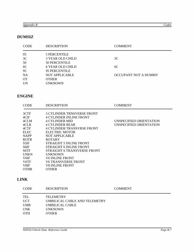
Codes Appendix B
Page B-36 NHTSA Vehicle Data Reference Guide
SENATT (continued)
CODE DESCRIPTION COMMENT
LCA6 LOAD CELL A6LCA7 LOAD CELL A7LCA8 LOAD CELL A8LCA9 LOAD CELL A9LCB0 LOAD CELL B10LCBI LOAD CELL B1LCB2 LOAD CELL B2LCB3 LOAD CELL B3LCB4 LOAD CELL B4LCB5 LOAD CELL B5LCB6 LOAD CELL B6LCB7 LOAD CELL B7LCB8 LOAD CELL B8LCB9 LOAD CELL B9LCC0 LOAD CELL C10LCC1 LOAD CELL C1LCC2 LOAD CELL C2LCC3 LOAD CELL C3LCC4 LOAD CELL C4LCC5 LOAD CELL C5LCC6 LOAD CELL C6LCC7 LOAD CELL C7LCC8 LOAD CELL C8LCC9 LOAD CELL C9LCD0 LOAD CELL D10LCD1 LOAD CELL D1 LCD2 LOAD CELL D2LCD3 LOAD CELL D3LCD4 LOAD CELL D4LCD5 LOAD CELL D5LCD6 LOAD CELL D6LCD7 LOAD CELL D7LCD8 LOAD CELL D8LCD9 LOAD CELL D9LPBI LAP BELT - INBOARDLPBO LAP BELT - OUTBOARDNEKL NECK - LOWERNEKU NECK - UPPERPOLE POLEPULM PULMONARY SYSTEMPVCN PELVIS - CENTER
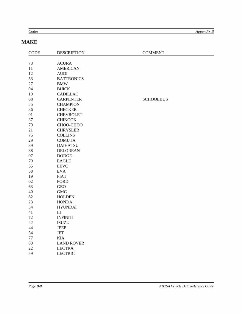
Appendix B Codes
NHTSA Vehicle Data Reference Guide Page B-37
SENATT (continued)
CODE DESCRIPTION COMMENT
PVHP PELVIS - H-POINT TROCHANTERIONPVIL PELVIS - ILIACPVPS PELVIS PUBIC SYMPHYSISPVSA PELVIS, SACRUMRAXL REAR AXLERBLA RIB - LOWER ABDOMENRBLL RIB - LEFT LOWERRBLM RIB - LEFT MIDDLERBLU RIB - LEFT UPPERRBRL RIB - RIGHT LOWERRBRM RIB - RIGHT MIDDLERBRU RIB - RIGHT UPPERRBUA RIB - UPPER ABDOMENREDK REAR DECKROLC ROLLOVER CARTRRLF ROOF RAIL LEFT FRONTRRLR ROOF RAIL LEFT REARRRRF ROOF RAIL RIGHT FRONTRRRR ROOF RAIL RIGHT REAR SECF SEAT - CENTERFRONTSECR SEAT - CENTER REARSELF SEAT - LEFT FRONTSELR SEAT - LEFT REARSERF SEAT - RIGHT FRONTSERR SEAT - RIGHT REARSHBE SHOULDER BELT EXTENS'NSHBT SHOULDER BELTSHLL SHOULDER - LEFTSHLR SHOULDER - RIGHTSLED SLEDSNML STERNUM - LOWERSNMU STERNUM - UPPERSPNL SPINE - LOWER T12SPNM SPINE - MIDDLE T04SPNU SPINE - UPPER T01STCL STEERING COLUMNSTLF SEAT TRACK - LEFT FRONTSTLR SEAT TRACK - LEFF REARSTRF SEAT TRACK - RIGHT FRONT
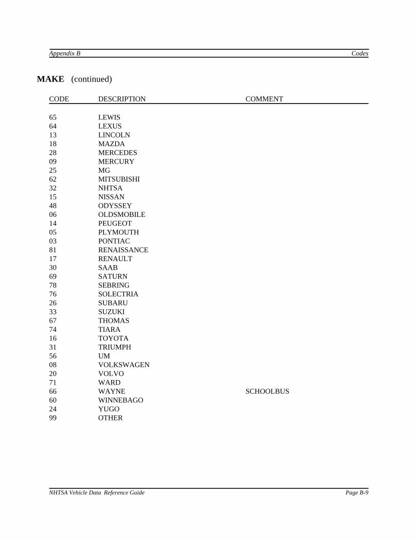
Codes Appendix B
Page B-38 NHTSA Vehicle Data Reference Guide
SENATT (continued)
CODE DESCRIPTION COMMENT
STRR SEAT TRACK - RIGHT REARSULF SUSPENSION - LEFT FRONTSULR SUSPENSION - LEFT REARSURF SUSPENSION - RIGHT FRONTSURR SUSPENSION - RIGHT REARSWHB STEERING WHEEL HUBSWRM STEERING WHEEL RIMTIBL TIBIA - LEFTTIBR TIBIA - RIGHTTRFC TRUCK FLOOR - CENTERTRFL TRUCK FLOOR - LEFTTRFR TRUCK FLOOR - RIGHTVECG VEHICLE CGOTHR OTHER
SENLOC
CODE DESCRIPTION COMMENT
01 LEFT FRONT SEAT02 RIGHT FRONT SEAT03 RIGHT REAR SEAT04 LEFT REAR SEAT05 CENTER FRONT SEAT06 CENTER REAR SEAT07 LEFT THIRD SEAT STATION WAGON/VAN08 CENTER THIRD SEAT STATION WAGON/VAN09 RIGHT THIRD SEAT STATION WAGON/VANNA NOT APPLICABLEOT OTHER OR OUT OF POSITION
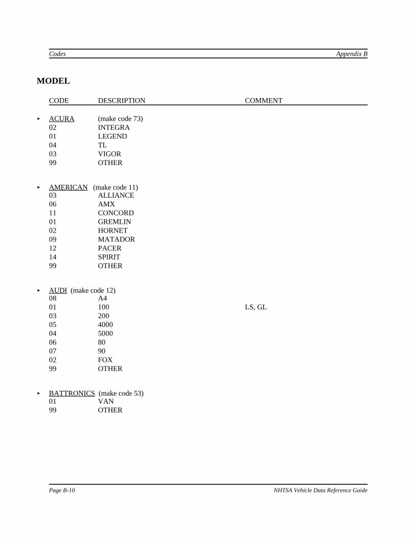
Appendix B Codes
NHTSA Vehicle Data Reference Guide Page B-39
SENTYP
CODE DESCRIPTION COMMENT
AA ANGULAR ACCELEROMETERAC ACCELEROMETERAD ANGULAR DSPLCMENT TRANSDUCERAV ANGULAR VELOCITY TRANSDUCERDS DISPLACEMENT TRANSDUCERET EVENT TIME INDICATOR ON/OFF STYLE SWITCHHL HIGH LEVELLC LOAD CELLPR PRESSURE TRANSDUCERSG STRAIN GAUGETB TIME BASED CHANNELVL VELOCITY TRANSDUCEROT OTHER
SEPOSN
CODE DESCRIPTION COMMENT
CN CENTER POSITION OF ADJUSTMENT RANGEFW FORWARD OF CENTER POSITIONNO NONADJUSTABLE SEATRW REARWARD OF CENTER POSITIONUN UNKNOWN
SILENG
CODE DESCRIPTION COMMENT
DE DIRECT ENGAGEMENT BY COLLIDING OBJECTNA NOT APPLICABLENO NO DIRECT ENGAGEMENTUN UNKNOWN

Codes Appendix B
Page B-40 NHTSA Vehicle Data Reference Guide
STRSEP
CODE DESCRIPTION COMMENT
NA NOT APPLICABLE NO STEERING COLUMN SHEAR CAPSULENO NO SEPARATION OF STEERING COLUMN SHEAR CAPSULESP SEPARATION OF STEERING COLUMN SHEAR CAPSULEUN UNKNOWN
TKCOND
CODE DESCRIPTION COMMENT
DRY DRYICY ICYMUD MUDDYSAN SANDYSNO SNOWYUNK UNKNOWNWET WETOTH OTHER
TKSURF
CODE DESCRIPTION COMMENT
ASH ASPHALTCON CONCRETEDOS DIRT OR SANDUNK UNKNOWNOTH OTHER

Appendix B Codes
NHTSA Vehicle Data Reference Guide Page B-41
TRANSM
CODE DESCRIPTION COMMENT
A4 AUTOMATIC - FOUR WHEEL DRIVEAF AUTOMATIC - FRONT WHEEL DRIVEAR AUTOMATIC - REAR WHEEL DRIVEM4 MANUAL - 4 WHEEL DRIVEMF MANUAL - FRONT WHEEL DRIVEMR MANUAL - REAR WHEEL DRIVENA NOT APPLICABLEUN UNKNOWNOT OTHER
TSTCFN
CODE DESCRIPTION COMMENT
ITB IMPACTOR INTO BARRIERITI IMPACTOR INTO IMPACTORITV IMPACTOR INTO VEHICLEROL ROLLOVERSLB SLED WITH VEHICLE BODYVTB VEHICLE INTO BARRIERVTI VEHICLE INTO IMPACTORVTV VEHICLE INTO VEHICLEOTH OTHER

Codes Appendix B
Page B-42 NHTSA Vehicle Data Reference Guide
TSTPRF
CODE DESCRIPTION COMMENT
AUT AUTLIV AUSTRALIA P/LBAS BUNDESANTALT FUER STRASSENWESECAL CALSPANCAN TRANSPORT CANADADYS DYNAMIC SCIENCEENS ENSCOFOI FEDERAL OUTDOOR IMPACT LABORATORYFRD FORD MOTOR COMPANYGMC GENERAL MOTORS CORP.HDL HEIDELBERGIIH INSURANCE INSTITUTE FOR HIGHWAY
SAFETYKAR KARCO ENGINEERINGMCR MCR TECHNOLOGY FORMERLY MINICARSMCW MEDICAL COLLEGE OF WISCMGA MGA RESEARCHMSE MOBILITY SYSTEMSNTC NTS - CALIFORNIA FORMERLY AETL - CALIFORNIANTV NTS - VIRGINIA FORMERLY AETL - VIRGINIAONS ONSERSWR SWRITNO TNO-RD.VEH. RES'RCH INST.TRC TRC OF OHIOTTI TEXAS TRANSP. INSTITUTEUVA UNIVERSITY OF VIRGINIAVWG VOLKSWAGEN AGOTH OTHER

Appendix B Codes
NHTSA Vehicle Data Reference Guide Page B-43
TSTTYP
CODE DESCRIPTION COMMENT
208 COMPLIANCE - FMVSS 208 OCCUPANT CRASH PROTECTIONCOMPLIANCE TEST
214 COMPLIANCE - FMVSS 214 SIDE IMPACT PROTECTION COMPLIANCETEST
301 COMPLIANCE - FMVSS 214 FUEL SYSTEM INTEGRITY COMPLIANCETEST
303 COMPLIANCE - FMVSS 303 FUEL SYSTEM INTEGRITY OF CNGVEHICLES
BAS BASELINE TEST CONVENTIONAL VEHICLE(S)CLB CALIBRATION TESTCOM COMPLIANCE TEST OTHERCRC CRASH RECORDER TESTDEV TEST PROCEDURE DEVEL.ELE ELECTRIC VEHICLE TESTENC EXPERIMENTAL NEW CAR
ASSESSMENT TESTINV INVALIDATED TESTMOD MODIFIED VEHICLE TEST STRUCTURAL AND/OR INTERIOR
MODIFICATIONSNCA NEW CAR ASSESSMENT TESTOCC OCC PERFORMANCE TESTONC OPTIONAL NEW CAR ASSESSMENT TESTRSB ROADSIDE BARRIER TESTRSV RESEARCH SAFETY VEH. TESTRWS REAL WORLD SIMULATIONUNK UNKNOWNOTH OTHER
UNITS
CODE DESCRIPTION COMMENT
CEN DEGREES CELSIUS TEMPERATUREDEC DECIBELS SOUNDDEG DEGREES ANGULAR DISPLACEMENTDP2 DEG/SEC(2) ANGULAR ACCELERATIONDPS DEG/SEC ANGULAR VELOCITYG'S G'S ACCELERATION

Codes Appendix B
Page B-44 NHTSA Vehicle Data Reference Guide
UNITS (continued)
CODE DESCRIPTION COMMENT
KPA KILOPASCALS ABSOLUTE PRESSUREKPG KILOPASCALS GAUGE PRESSUREKPH KILOMETERS/HOUR VELOCITYMM MILLIMETERS DISPLACEMENTMPM MICROMET/MET STRAINNON DIMENSIONLESS DIMENSIONLESSNSC NEWTON-SECONDS IMPULSENWM NEWTON-METERS TORQUENWT NEWTONS FORCEPST PERCENT STRAIN STRAINRMM RECIPROCAL MM CURVATURESEC SECONDS TIMEVOL VOLTS VOLTAGEOTH OTHER OTHER


Codes Appendix B
Page B-8 NHTSA Vehicle Data Reference Guide
MAKE
CODE DESCRIPTION COMMENT
73 ACURA11 AMERICAN12 AUDI53 BATTRONICS27 BMW04 BUICK10 CADILLAC68 CARPENTER SCHOOLBUS35 CHAMPION36 CHECKER01 CHEVROLET37 CHINOOK79 CHOO-CHOO21 CHRYSLER75 COLLINS29 COMUTA39 DAIHATSU38 DELOREAN07 DODGE70 EAGLE55 EEVC58 EVA19 FIAT02 FORD63 GEO40 GMC82 HOLDEN23 HONDA34 HYUNDAI41 IH72 INFINITI42 ISUZU44 JEEP54 JET77 KIA80 LAND ROVER22 LECTRA59 LECTRIC
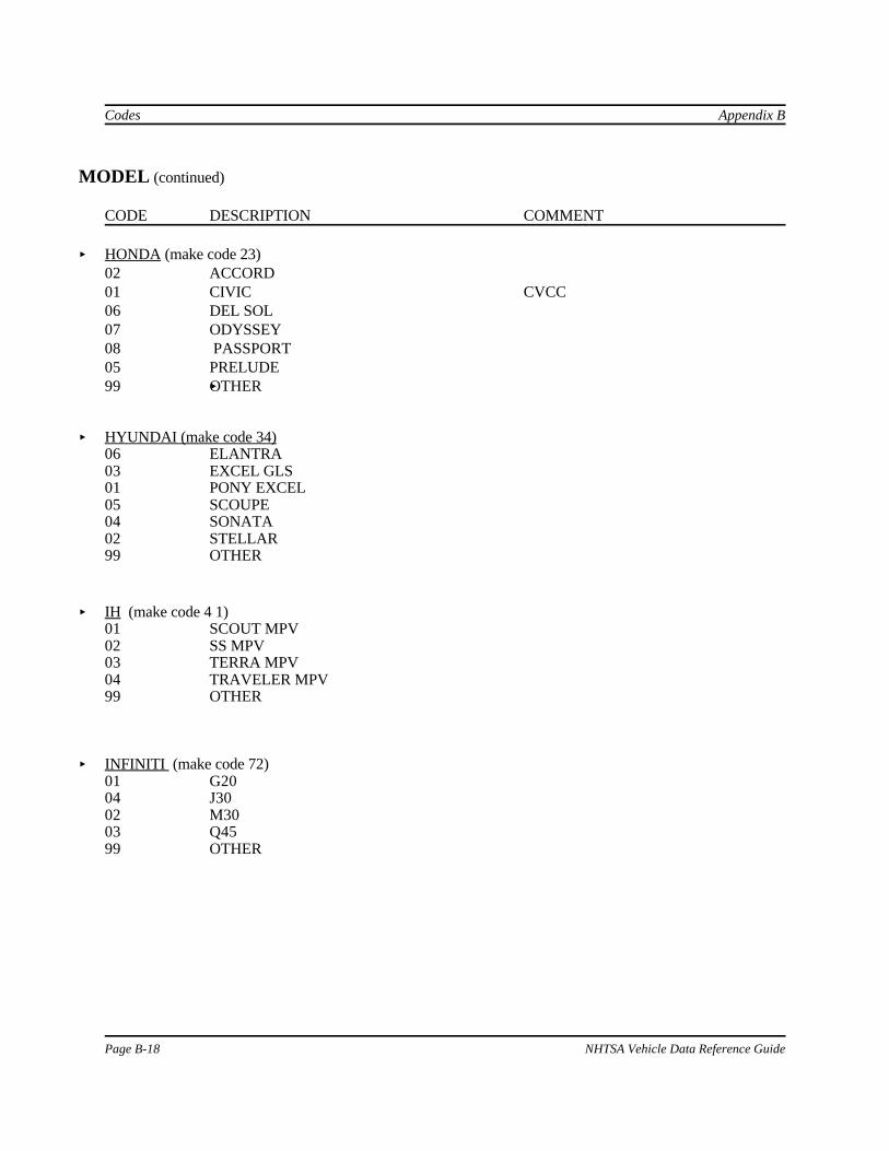
Appendix B Codes
NHTSA Vehicle Data Reference Guide Page B-9
MAKE (continued)
CODE DESCRIPTION COMMENT
65 LEWIS64 LEXUS13 LINCOLN18 MAZDA28 MERCEDES09 MERCURY25 MG62 MITSUBISHI32 NHTSA15 NISSAN 48 ODYSSEY06 OLDSMOBILE14 PEUGEOT05 PLYMOUTH03 PONTIAC81 RENAISSANCE17 RENAULT30 SAAB69 SATURN78 SEBRING76 SOLECTRIA26 SUBARU33 SUZUKI67 THOMAS 74 TIARA16 TOYOTA31 TRIUMPH56 UM08 VOLKSWAGEN20 VOLVO 71 WARD66 WAYNE SCHOOLBUS60 WINNEBAGO24 YUGO99 OTHER

Field Formats Appendix C
Page C-6 NHTSA Vehicle Data Reference Guide
3. BARRIER INFORMATION
FIELD NAME DATA TYPE MAXIMUM FIELDLENGTH/RANGE
TSTNO predefined text=0 1char
BARRIG coded text 1 char
BARSHP coded text 3 char
BARANG integer 0 to 90
BARDIA integer 0 to 9999
BARCOM free text 70 char
4. OCCUPANT INFORMATION
FIELD NAME DATA TYPE MAXIMUM FIELDLENGTH/RANGE
TSTNO predefined text=0 1 char
VEHNO integer 1 to 2
OCCLOC coded text 2 char
OCCTYP coded text 2 char
OCCAGE integer 0 to 99
OCCSEX coded text 1 char
OCCHT integer 0 to 9999
OCCWT integer 0 to 999
MTHCAL coded text 2 char
DUMSIZ coded text 2 char
DUMMAN free text 70 char

Appendix C: Field Formats
NHTSA Vehicle Data Reference Guide Page C -7
4. OCCUPANT INFORMATION (continued)
FIELD NAME DATA TYPE MAXIMUM FIELDLENGTH/RANGE
DUMMOD free text 70 char
DUMDSC free text 70 char
HH integer 0 to 9999
HW integer 0 to 9999
HR integer 0 to 9999
HS integer 0 to 9999
CD integer 0 to 9999
CS integer 0 to 9999
AD integer 0 to 9999
HD integer 0 to 9999
KD integer 0 to 9999
HB integer 0 to 9999
NB integer 0 to 9999
CB integer 0 to 9999
KB integer 0 to 9999
SEPOSN coded text 2 char
CNTRH1 coded text 2 char
CNTRH2 coded text 2 char
CNTRC1 coded text 2 char
CNTRC2 coded text 2 char
CNTRL1 coded text 2 char

Field Formats Appendix C
Page C-8 NHTSA Vehicle Data Reference Guide
4. OCCUPANT INFORMATION (continued)
FIELD NAME DATA TYPE MAXIMUM FIELDLENGTH/RANGE
CNTRL2 coded text 2 char
HIC integer 0 to 9999
T1 float 0 to 999999 (max)
T2 float 0 to 999999 (max)
CLIP3M float 0 to 99999
LFEM integer -99999 to 0
RFEM integer -99999 to 0
CSI integer 0 to 9999
LBELT integer 0 to 99999
SBELT integer 0 to 99999
TTI float 0 to 99999
PELVG float 0 to 99999
OCCCOM free text 70 char

Appendix C: Field Formats
NHTSA Vehicle Data Reference Guide Page C -9
5. RESTRAINTS INFORMATION
FIELD NAME DATA TYPE MAXIMUM FIELDLENGTH/RANGE
TSTNO predefined text=0 1char
VEHNO integer 1 to 2
OCCLOC coded text 2 char
RSTNO integer 1 to 9
RSTTYP coded text 3 char
RSTMNT coded text 2 char
DEPLOY coded text 2 char
RSTCOM free text 70 char
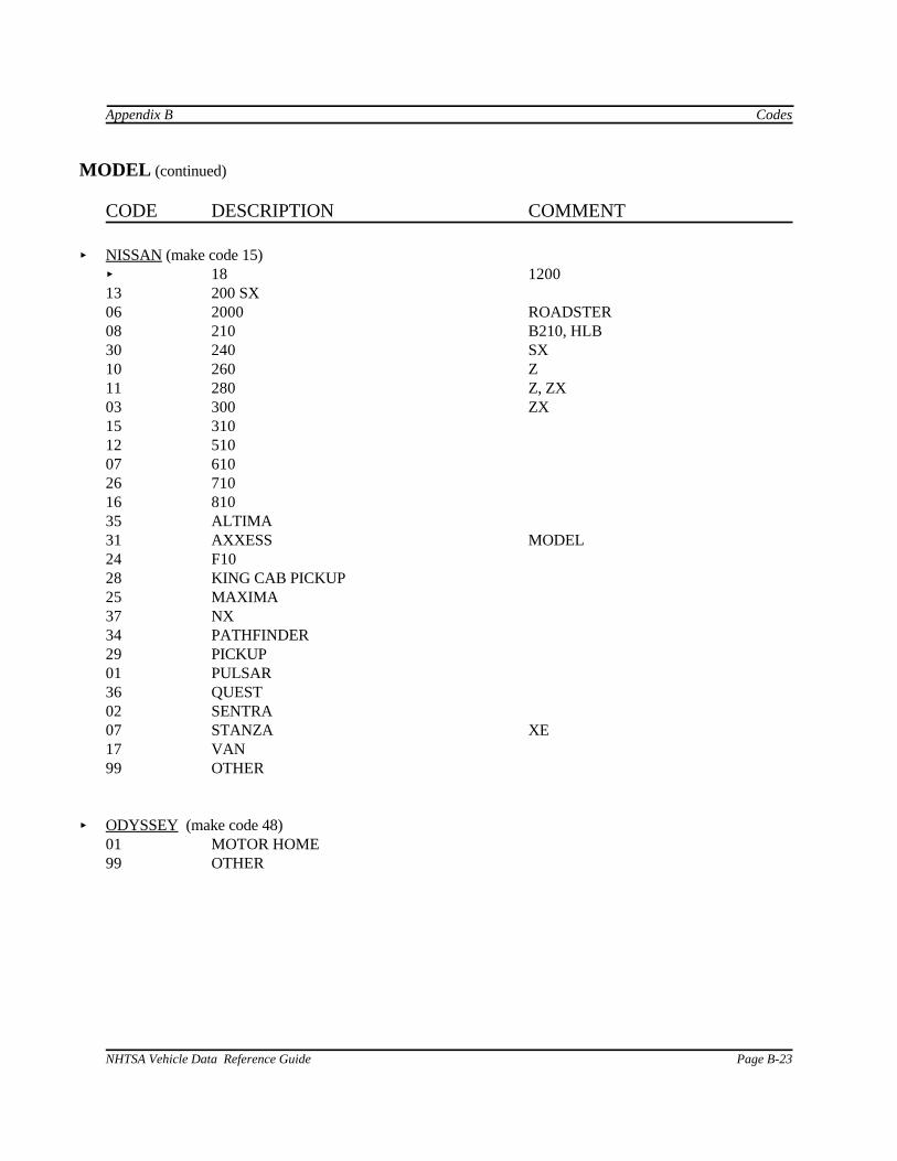
Field Formats Appendix C
Page C-10 NHTSA Vehicle Data Reference Guide
6. INSTRUMENTATION INFORMATION
FIELD NAME DATA TYPE MAXIMUM FIELDLENGTH/RANGE
TSTNO predefined text=0 1 char
VEHNO integer 1 to 2
CURNO integer 1 to 200
SENTYP coded text 2 char
SENLOC coded text 2 char
SENATT coded text 4 char
AXIS coded text 2 char
UNITS coded text 3 char
PREFIL integer 0 to 99999
INSMAN free text 70 char
CALDAT date text 11 char(DD/MMM/YYYY)
INSRAT integer -999999 to 999999
CHLMAX integer 0 to 100
INIVEL float -200 to 200
NFP integer -10000 to 0
NLP integer 0 to 99999
DELT integer 0 to 999999
DASTAT coded text 2 char
CHSTAT coded text 1 char
INSCOM free text 70 char

NHTSA Vehicle Data Reference Guide Page D-1
APPENDIX D:DATA COORDINATE SYSTEM
With the introduction of this version (V4) of the NHTSA data format, all submissions will conform toSAE J211/1 MAR95 Instrumentation for Impact Test. Please refer to SAE J211 for a completedescription of the coordinate system and signal polarities for vehicle occupants.
USING THE COORDINATE SYSTEM CORRECTLY
The rules for determining the sign conventions described below will enable anyone involved inNHTSA-sponsored testing to determine the proper sign and coordinate axis for any measuredquantity.
All coordinate systems are orthoganol, three-dimensional, and right handed. The global coordinatesystems for the vehicle and the test occupants are shown in Figure D-1. The coordinate system forthe nine accelerometer head array is shown in Figure D-2, along with the proper SENATT codes. Table D-1 lists the polarity of the sensor output from various dummy manipulations when using thiscoordinate system.
VEHICLE GLOBAL COORDINATE SYSTEM
< X is positive forward
< Y is positive right (toward the passenger side door)
< Z is positive down
OCCUPANT GLOBAL COORDINATE SYSTEM (all occupant types - OCCTYP)
< X is positive forward (posterior to anterior)
< Y is positive right
< Z is positive down
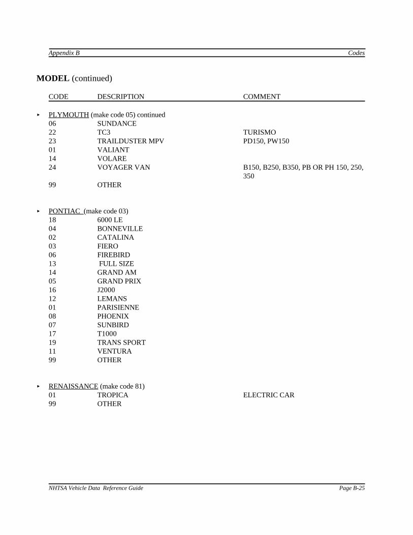
Data Coordinate System Appendix D
Page D-2 NHTSA Vehicle Data Reference Guide
Figure D-1: Vehicle and Body-Based Coordinate Systems

Appendix D Data Coordinate System
NHTSA Vehicle Data Reference Guide Page D-3
Figure D-2: Coordinate System for 9-Accelerometer Array
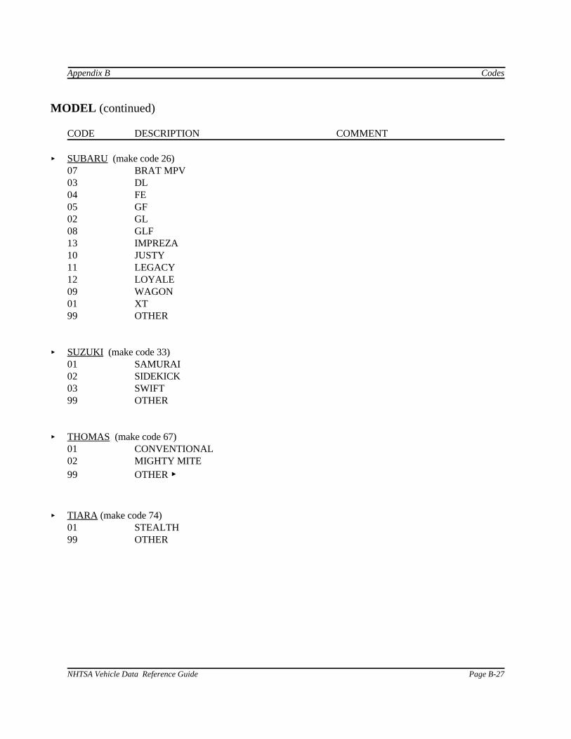
Data Coordinate System Appendix D
Page D-4 NHTSA Vehicle Data Reference Guide
TABLE D.1Dummy Manipulations for Checking Recorded Load Cell
Polarity Relative to Sign Convention -----------------------------------------------------------------------------------------------------Load Cell Measure Dummy Manipulations Polarity------------------------------------------------------------------------------------------------------------------Upper Fx Head readward, chest forward + and Fy Head leftward, chest rightward +lower Fz Head upward, chest downward + neck Mx Left ear toward left shoulder +loads My Chin toward sternum +
Mz Chin toward left shoulder +-------------------------------------------------------------------------------------------------------------------Left shoulder Fx Left shoulder forward, chest rearward + loads Fy Left shoulder rightward, chest leftward + (BIOSID) Fz Left shoulder downward, chest upward +-------------------------------------------------------------------------------------------------------------------Right shoulder Fx Right shoulder forward, chest rearward + loads Fy Right shoulder rightward, chest leftward + (BIOSID) Fz Right shoulder downward, chest upward +-------------------------------------------------------------------------------------------------------------------Clavicle Fx Shoulder forward, chest rearward + loads Fz Shoulder downward, chest rearward +------------------------------------------------------------------------------------------------------------------- Upper Fx Chest rearward, Pelvis forward + and Fy Chest leftward, pelvis rightward + lower Fz Chest upward, pelvis downward + lumbar Mx Left shoulder toward left hip + spine My Sternum toward front of legs +
Mz Right shoulder forward, left shoulder rearward +-------------------------------------------------------------------------------------------------------------------Sacrum load Fy Left H-point pad leftward, chest rightward + (BIOSID)-------------------------------------------------------------------------------------------------------------------Left iliac load Fy Left iliac rightward, chest leftward + (BIOSID)-------------------------------------------------------------------------------------------------------------------

Appendix D Data Coordinate System
NHTSA Vehicle Data Reference Guide Page D-5
TABLE D.1 (continued)-------------------------------------------------------------------------------------------------------------------Load Cell Measure Dummy Manipulations Polarity-------------------------------------------------------------------------------------------------------------------Right iliac load Fy Right iliac rightward, chest leftward + (BIOSID)-------------------------------------------------------------------------------------------------------------------Pubic load Fy Right H-point pad leftward, left pad rightward (-)(side impact)-------------------------------------------------------------------------------------------------------------------Crotch belt Fx Pubic rearward, pelvis forward (-) loads Fz Pubic upward, chest downward (-)-----------------------------------------------------------------------------------------------------------------Iliac lap belt Fx Upper iliac spine rearward, chest forward (-) loads My Upper iliac spine rearward, chest forward +-------------------------------------------------------------------------------------------------------------------Left side Fy Left side of abdomen rightward, +abdominal load chest leftward(Eurosid-1)-------------------------------------------------------------------------------------------------------------------Right side Fy Right side of abdomen leftward, (-)abdominal load chest rightward(Eurosid-1)-------------------------------------------------------------------------------------------------------------------Femur loads Fx Knee upward, upper femur downward +
Fy Knee rightward, upper femur leftward +(dummy in Fz Knee forward, pelvis rearward +seated position, Mx Knee leftward, hold upper femur in place +femurs My Knee upward, hold upper femur in place +horizontal) Mz Tibia leftward, hold pelvis in place +-------------------------------------------------------------------------------------------------------------------Knee clevis Fz Tibia downward, femur upward +-------------------------------------------------------------------------------------------------------------------Upper tibia Fz Tibia downward, femur upward + loads Mx Ankle leftward, hold knee in place +
My Ankle forward, bottom of knee clevis rearward +-------------------------------------------------------------------------------------------------------------------Lower tibia Fx Ankle forward, knee rearward + loads Fy Ankle rightward, knee leftward +
Mx Ankle leftward, hold knee in place +My Ankle forward, bottom of knee clevis rearward +