Embed Size (px)
Citation preview

Data ONTAP® 8.0 7-ModeNetwork Management Guide
NetApp, Inc.495 East Java DriveSunnyvale, CA 94089 U.S.A.Telephone: +1 (408) 822-6000Fax: +1 (408) 822-4501Support telephone: +1 (888) 4-NETAPPDocumentation comments: [email protected] Web: http://www.netapp.com
Part number: 210-04909_B0Updated for Data ONTAP 8.0.1 on 04 November 2010


Contents
Copyright information ............................................................................... 11Trademark information ............................................................................. 13About this guide .......................................................................................... 15
Audience .................................................................................................................... 15
Accessing Data ONTAP man pages .......................................................................... 16
Terminology .............................................................................................................. 16
Where to enter commands ......................................................................................... 17
Keyboard and formatting conventions ...................................................................... 18
Special messages ....................................................................................................... 19
How to send your comments ..................................................................................... 19
Network interfaces on your storage system ............................................. 21Network interface naming ......................................................................................... 21
Maximum number of network interfaces .................................................................. 23
The e0M interface ..................................................................................................... 24
How to use the RLM or BMC to manage Data ONTAP remotely ........................... 25
Ways to configure the RLM .......................................................................... 25
Ways to configure the BMC .......................................................................... 26
How TSO increases outbound throughput ................................................................ 26
Data ONTAP support for TSO ...................................................................... 27
Viewing the TSO statistics ............................................................................ 27
How Data ONTAP uses ACP to increase storage availability .................................. 28
Enabling ACP ................................................................................................ 29
The ACP subnet ............................................................................................ 30
Standards and characteristics of Ethernet frames .................................. 31What jumbo frames are ............................................................................................. 31
Network interface requirements for jumbo frames ....................................... 32
Guidelines to configure clients for jumbo frames ......................................... 32
Flow control .............................................................................................................. 32
Network interface configuration ............................................................... 33Configuring network interfaces ................................................................................. 33
Configuring an IP address for a network interface ....................................... 34
Specifying a subnet mask for a network interface ........................................ 35
Table of Contents | 3

Specifying a broadcast address ..................................................................... 35
Specifying a media type for a network interface ........................................... 36
Specifying an MTU size for a network interface .......................................... 36
Specifying the flow control type for a network interface .............................. 37
Specifying whether a network interface is trusted ........................................ 37
Configuring a partner interface in an HA pair .............................................. 38
Enabling or disabling automatic takeover for a network interface ............... 39
Removing a primary IP address from a network interface ............................ 40
Viewing network interface settings ............................................................... 41
Creating or removing aliases ..................................................................................... 41
Changing the status of an interface ........................................................................... 42
Viewing or modifying interface settings with FilerView .......................................... 42
Blocking or unblocking protocols from network interfaces ...................................... 43
Network interface information you can view ............................................................ 44
Viewing statistics of all active TCP connections .......................................... 44
Viewing or clearing network interface statistics ........................................... 46
Viewing network interface information with FilerView ............................... 49
How routing in Data ONTAP works ........................................................ 51What fast path is ........................................................................................................ 51
How to manage the routing table .............................................................................. 52
What the routed daemon does ....................................................................... 53
When the routed daemon should be turned off ............................................. 53
Routing tables in a vFiler unit environment .................................................. 54
Circumstances that might alter the routing table ........................................... 54
Specifying the default route ...................................................................................... 54
How to enable or disable routing mechanisms .......................................................... 55
Enabling or disabling fast path ...................................................................... 55
Enabling or disabling the routed daemon from the command-line
interface ................................................................................................... 56
Enabling or disabling the routed daemon with FilerView ............................ 56
How to view the routing table and default route information ................................... 57
Viewing the routing table from the command-line interface ........................ 57
Viewing the default route information from the command-line interface .... 58
Viewing the routing table and routing information by using FilerView ....... 59
Modifying the routing table ....................................................................................... 59
How to maintain host-name information ................................................. 61
4 | Data ONTAP 8.0 7-Mode Network Management Guide

How the /etc/hosts file works .................................................................................... 61
Adding a host name in the /etc/hosts file ...................................................... 62
Hard limits for the /etc/hosts file ................................................................... 63
Editing the /etc/hosts file with FilerView ..................................................... 63
Changing the host name of a storage system ................................................ 63
How to configure DNS to maintain host information ............................................... 64
Configuring DNS from the command-line interface ..................................... 65
How DNS resolves host names ..................................................................... 66
DNS name caching ........................................................................................ 66
DNS information you can view ..................................................................... 66
How to use dynamic DNS to update host information .............................................. 67
How dynamic DNS updates work in Data ONTAP ...................................... 68
Support for dynamic DNS updates in Data ONTAP ..................................... 68
Enabling or disabling dynamic DNS updates ............................................... 69
Disabling the transmission of DNS updates for an IP address ...................... 69
Changing the time-to-live setting for DNS entries ........................................ 70
How to use NIS to maintain host information ........................................................... 70
How using NIS slaves can improve performance ......................................... 71
How an NIS master is selected ...................................................................... 71
Creating /etc/hosts from the NIS master ....................................................... 72
Guidelines for using NIS slaves .................................................................... 72
NIS administrative commands ...................................................................... 73
How to configure NIS with Data ONTAP interfaces ................................................ 73
Enabling or disabling NIS using the command-line interface ...................... 74
Specifying the NIS domain name .................................................................. 74
Specifying NIS servers to bind to your storage system ................................ 75
Enabling an NIS slave on your storage system ............................................. 75
What NIS information you can view ......................................................................... 76
Viewing NIS performance statistics .............................................................. 77
Configuring DNS and NIS with FilerView ............................................................... 78
How to change the host-name search order .............................................................. 79
Changing the host-name search order with FilerView .................................. 79
Changing the host-name search order ........................................................... 80
How VLANs work ...................................................................................... 81VLAN membership ................................................................................................... 81
How VLAN membership affects communication ......................................... 82
Table of Contents | 5
GARP VLAN Registration Protocol ......................................................................... 83
GVRP configuration for VLAN interfaces ................................................... 83
VLAN tags ................................................................................................................ 83
Advantages of VLANs .............................................................................................. 84
Prerequisites for setting up VLANs .......................................................................... 85
Guidelines for setting up VLANs in Data ONTAP ................................................... 85
The vlan command syntax ......................................................................................... 86
Creating a VLAN ...................................................................................................... 86
Configuring a VLAN ................................................................................................ 88
How to use VLANs for tagged and untagged network traffic ...................... 89
Adding an interface to a VLAN ................................................................................ 89
Deleting VLANs ....................................................................................................... 90
Enabling or disabling GVRP on your VLAN interface ............................................ 91
Viewing VLAN statistics .......................................................................................... 92
Viewing statistics for a specific VLAN .................................................................... 92
How interface groups work in Data ONTAP ........................................... 95Types of interface groups .......................................................................................... 96
Single-mode interface group ......................................................................... 97
Static multimode interface group .................................................................. 97
Dynamic multimode interface group ............................................................. 98
Load balancing in multimode interface groups ....................................................... 100
IP address and MAC address load balancing .............................................. 100
Round-robin load balancing ........................................................................ 100
Port-based load balancing ........................................................................... 100
Guidelines for configuring interface groups ........................................................... 101
The ifgrp command ................................................................................................. 101
Creating a single-mode interface group .................................................................. 102
Selecting an active interface in a single-mode interface group ................... 103
Designating a nonfavored interface in a single-mode interface group ........ 104
Failure scenarios for a single-mode interface group ................................... 105
Creating a static multimode interface group ........................................................... 105
Creating a dynamic multimode interface group ...................................................... 107
Adding interfaces to an interface group .................................................................. 108
Deleting interfaces from an interface group ............................................................ 109
Viewing interface group status ................................................................................ 110
What the interface group status information table contains ........................ 111
6 | Data ONTAP 8.0 7-Mode Network Management Guide

Viewing interface group statistics ........................................................................... 112
Destroying an interface group ................................................................................. 113
Second-level interface groups ................................................................................. 113
Guidelines for creating a second-level interface group ............................... 114
Creating a second-level interface group ...................................................... 114
Enabling failover in a second-level interface group .................................... 115
Second-level interface groups in an HA pair .......................................................... 116
Creating a second-level interface group in an HA pair ............................... 117
How CDP works with Data ONTAP ....................................................... 121Considerations for using CDP ................................................................................. 121
Enabling or disabling CDP on your storage system ................................................ 122
Configuring hold time for CDP messages ............................................................... 122
Setting the intervals for sending CDP advertisements ............................................ 123
Viewing or clearing CDP statistics ......................................................................... 123
Viewing neighbor information by using CDP ......................................................... 125
How to monitor your storage system with SNMP ................................. 127Types of SNMP traps in Data ONTAP ................................................................... 127
What a MIB is ......................................................................................................... 128
What the SNMP agent does .................................................................................... 128
How to configure the SNMP agent ......................................................................... 128
Enabling or disabling SNMP using the command-line interface ................ 130
Configuring SNMPv3 users ........................................................................ 130
Setting SNMP access privileges .................................................................. 131
Viewing or modifying your SNMP configuration from the command-
line interface .......................................................................................... 131
Modifying your SNMP configuration from FilerView ............................... 132
SNMP command syntax .............................................................................. 132
SNMP security parameters .......................................................................... 133
Example: SNMP commands ....................................................................... 134
User-defined SNMP traps ....................................................................................... 135
How SNMP traps work ............................................................................... 136
How to define or modify a trap ................................................................... 136
Viewing or modifying trap values from the command-line interface ......... 137
Viewing or modifying trap values from FilerView ..................................... 137
Defining traps in a configuration file .......................................................... 137
Example: Trap definitions ........................................................................... 138
Table of Contents | 7

Command syntax for SNMP trap parameters ............................................. 139
SNMP trap parameters ................................................................................ 139
How to diagnose network problems ........................................................ 145Diagnosing transport layer problems ...................................................................... 145
Viewing diagnostic results ...................................................................................... 146
How to diagnose ping problems .............................................................................. 146
Increasing the ping throttling threshold value ............................................. 147
Checking the ping throttling threshold status .............................................. 147
Disabling ping throttling ............................................................................. 147
Protecting your storage system from forged ICMP redirect attacks ....................... 148
Network interface statistics ..................................................................... 149Statistics for Gigabit Ethernet controller VI, VII, and G20 interfaces .................... 149
Statistics for Gigabit and 10 Gigabit Ethernet controllers T204, T210, and T320
interfaces ............................................................................................................ 153
Statistics for the BGE 10/100/1000 Ethernet interface ........................................... 156
Statistics for 10 Gigabit Ethernet Controller IX1 - SFP+ ....................................... 159
Statistics for Dual 10G Ethernet Controller CNA - SFP+ ...................................... 162
Ways to improve your storage system's performance .......................... 165IP port usage on a storage system ........................................................... 167
Host identification ................................................................................................... 167
/etc/services NNTP and TTCP ports ....................................................................... 170
NFS-enabled ports ................................................................................................... 170
Ports not listed in /etc/services ................................................................................ 172
FTP .......................................................................................................................... 172
SSH .......................................................................................................................... 173
Telnet ....................................................................................................................... 173
SMTP ...................................................................................................................... 174
Time service ............................................................................................................ 174
DNS ......................................................................................................................... 174
DHCP ...................................................................................................................... 175
TFTP ........................................................................................................................ 175
HTTP ....................................................................................................................... 175
Kerberos .................................................................................................................. 176
NFS .......................................................................................................................... 176
CIFS ........................................................................................................................ 177
SSL .......................................................................................................................... 177
8 | Data ONTAP 8.0 7-Mode Network Management Guide

SNMP ...................................................................................................................... 177
RSH ......................................................................................................................... 178
Syslog ...................................................................................................................... 179
The routed daemon .................................................................................................. 179
NDMP ..................................................................................................................... 179
SnapMirror and SnapVault ...................................................................................... 180
Error codes for the netdiag command .................................................... 181Index ........................................................................................................... 185
Table of Contents | 9


Copyright information
Copyright © 1994–2010 NetApp, Inc. All rights reserved. Printed in the U.S.A.
No part of this document covered by copyright may be reproduced in any form or by any means—graphic, electronic, or mechanical, including photocopying, recording, taping, or storage in anelectronic retrieval system—without prior written permission of the copyright owner.
Software derived from copyrighted NetApp material is subject to the following license anddisclaimer:
THIS SOFTWARE IS PROVIDED BY NETAPP "AS IS" AND WITHOUT ANY EXPRESS ORIMPLIED WARRANTIES, INCLUDING, BUT NOT LIMITED TO, THE IMPLIEDWARRANTIES OF MERCHANTABILITY AND FITNESS FOR A PARTICULAR PURPOSE,WHICH ARE HEREBY DISCLAIMED. IN NO EVENT SHALL NETAPP BE LIABLE FOR ANYDIRECT, INDIRECT, INCIDENTAL, SPECIAL, EXEMPLARY, OR CONSEQUENTIALDAMAGES (INCLUDING, BUT NOT LIMITED TO, PROCUREMENT OF SUBSTITUTEGOODS OR SERVICES; LOSS OF USE, DATA, OR PROFITS; OR BUSINESSINTERRUPTION) HOWEVER CAUSED AND ON ANY THEORY OF LIABILITY, WHETHERIN CONTRACT, STRICT LIABILITY, OR TORT (INCLUDING NEGLIGENCE OROTHERWISE) ARISING IN ANY WAY OUT OF THE USE OF THIS SOFTWARE, EVEN IFADVISED OF THE POSSIBILITY OF SUCH DAMAGE.
NetApp reserves the right to change any products described herein at any time, and without notice.NetApp assumes no responsibility or liability arising from the use of products described herein,except as expressly agreed to in writing by NetApp. The use or purchase of this product does notconvey a license under any patent rights, trademark rights, or any other intellectual property rights ofNetApp.
The product described in this manual may be protected by one or more U.S.A. patents, foreignpatents, or pending applications.
RESTRICTED RIGHTS LEGEND: Use, duplication, or disclosure by the government is subject torestrictions as set forth in subparagraph (c)(1)(ii) of the Rights in Technical Data and ComputerSoftware clause at DFARS 252.277-7103 (October 1988) and FAR 52-227-19 (June 1987).
Copyright information | 11


Trademark information
NetApp; the NetApp logo; the Network Appliance logo; Bycast; Cryptainer; Cryptoshred;DataFabric; Data ONTAP; Decru; Decru DataFort; FAServer; FilerView; FlexCache; FlexClone;FlexShare; FlexVol; FPolicy; gFiler; Go further, faster; Manage ONTAP; MultiStore; NearStore;NetCache; NOW (NetApp on the Web); ONTAPI; RAID-DP; SANscreen; SecureShare; SimulateONTAP; SnapCopy; SnapDrive; SnapLock; SnapManager; SnapMirror; SnapMover; SnapRestore;SnapValidator; SnapVault; Spinnaker Networks; Spinnaker Networks logo; SpinAccess;SpinCluster; SpinFlex; SpinFS; SpinHA; SpinMove; SpinServer; SpinStor; StorageGRID;StoreVault; SyncMirror; Topio; vFiler; VFM; and WAFL are registered trademarks of NetApp, Inc.in the U.S.A. and/or other countries. Network Appliance, Snapshot, and The evolution of storage aretrademarks of NetApp, Inc. in the U.S.A. and/or other countries and registered trademarks in someother countries. The StoreVault logo, ApplianceWatch, ApplianceWatch PRO, ASUP, AutoSupport,ComplianceClock, DataFort, Data Motion, FlexScale, FlexSuite, Lifetime Key Management,LockVault, NOW, MetroCluster, OpenKey, ReplicatorX, SecureAdmin, Shadow Tape,SnapDirector, SnapFilter, SnapMigrator, SnapSuite, Tech OnTap, Virtual File Manager, VPolicy,and Web Filer are trademarks of NetApp, Inc. in the U.S.A. and other countries. Get Successful andSelect are service marks of NetApp, Inc. in the U.S.A.
IBM, the IBM logo, and ibm.com are trademarks or registered trademarks of International BusinessMachines Corporation in the United States, other countries, or both. A complete and current list ofother IBM trademarks is available on the Web at www.ibm.com/legal/copytrade.shtml.
Apple is a registered trademark and QuickTime is a trademark of Apple, Inc. in the U.S.A. and/orother countries. Microsoft is a registered trademark and Windows Media is a trademark of MicrosoftCorporation in the U.S.A. and/or other countries. RealAudio, RealNetworks, RealPlayer,RealSystem, RealText, and RealVideo are registered trademarks and RealMedia, RealProxy, andSureStream are trademarks of RealNetworks, Inc. in the U.S.A. and/or other countries.
All other brands or products are trademarks or registered trademarks of their respective holders andshould be treated as such.
NetApp, Inc. is a licensee of the CompactFlash and CF Logo trademarks.
NetApp, Inc. NetCache is certified RealSystem compatible.
Trademark information | 13


About this guide
You can use your product more effectively when you understand this document's intended audienceand the conventions that this document uses to present information.
This guide describes how to configure and manage network interfaces, interface groups, virtualLANs (VLANs), routing, and SNMP on storage systems that run Data ONTAP. This guide alsodescribes host-name resolution and SNMP.
This guide describes all storage system models; however, some models do not support all thenetworking interfaces. See the hardware guide for your storage system to identify which interfacesare supported on your system.
Note: This guide applies to systems running Data ONTAP 8.x 7-Mode, including V-Seriessystems. The 7-Mode in the Data ONTAP 8.x 7-Mode product name means that this release hasthe features and functionality you are used to if you have been using the Data ONTAP 7.0, 7.1,7.2, or 7.3 release families. If you are a Data ONTAP 8.x Cluster-Mode user, you use the DataONTAP 8.x Cluster-Mode guides plus any Data ONTAP 8.x 7-Mode guides for functionality youmight want to access with 7-Mode commands through the nodeshell.
Next topics
Audience on page 15
Accessing Data ONTAP man pages on page 16
Terminology on page 16
Where to enter commands on page 17
Keyboard and formatting conventions on page 18
Special messages on page 19
How to send your comments on page 19
AudienceThis document is written with certain assumptions about your technical knowledge and experience.
This document is for systems administrators who are familiar with operating systems that run onstorage system clients such as UNIX, MAC OSX, and Windows. It also assumes that you are familiarwith how Network File System (NFS), Common Internet File System (CIFS), and HyperTextTransfer Protocol (HTTP) are used for file sharing or transfers.
About this guide | 15

Accessing Data ONTAP man pagesYou can use the Data ONTAP manual (man) pages to access technical information.
About this task
Data ONTAP manual pages are available for the following types of information. They are groupedinto sections according to standard UNIX naming conventions.
Types of information Man page section
Commands 1
Special files 4
File formats and conventions 5
System management and services 8
Step
1. View man pages in the following ways:
• Enter the following command at the console command line:
man command_or_file_name
• Click the manual pages button on the main Data ONTAP navigational page in the FilerViewuser interface.
Note: All Data ONTAP 8.x 7-Mode man pages are stored on the system in files whosenames are prefixed with the string "na_" to distinguish them from other man pages. Theprefixed names sometimes appear in the NAME field of the man page, but the prefixes arenot part of the command, file, or service.
TerminologyTo understand the concepts in this document, you might need to know how certain terms are used.
Storage terms
storagecontroller
The component of a storage system that runs the Data ONTAP operating systemand controls its disk subsystem. Storage controllers are also sometimes calledcontrollers, storage appliances, appliances, storage engines, heads, CPU modules,or controller modules.
16 | Data ONTAP 8.0 7-Mode Network Management Guide

storagesystem
The hardware device running Data ONTAP that receives data from and sends datato native disk shelves, third-party storage, or both. Storage systems that run DataONTAP are sometimes referred to as filers, appliances, storage appliances, V-Series systems, or systems.
interfacegroup
In Data ONTAP 8.x, a single virtual interface that is created by grouping togethermultiple physical interfaces. In the Data ONTAP 7.2 and 7.3 release families, thisfunctionality is referred to as a vif.
Cluster and high-availability terms
cluster • In Data ONTAP 8.x Cluster-Mode, a group of connected nodes (storagesystems) that share a global namespace and that you can manage as a singlevirtual server or multiple virtual servers, providing performance, reliability,and scalability benefits.
• In the Data ONTAP 7.1 release family and earlier releases, a pair of storagesystems (sometimes called nodes) configured to serve data for each other ifone of the two systems stops functioning.
HA (highavailability)
In Data ONTAP 8.x, the recovery capability provided by a pair of nodes (storagesystems), called an HA pair, that are configured to serve data for each other if oneof the two nodes stops functioning.
HA pair In Data ONTAP 8.x, a pair of nodes (storage systems) configured to serve data foreach other if one of the two nodes stops functioning. In the Data ONTAP 7.3 and7.2 release families, this functionality is referred to as an active/activeconfiguration.
Where to enter commandsYou can use your product more effectively when you understand how this document uses commandconventions to present information.
You can perform common administrator tasks in one or more of the following ways:
Note: Data ONTAP commands shown in this document are for Data ONTAP 8.x 7-Mode and theData ONTAP 7.x release families. However, some of these commands might also be available atthe nodeshell prompt on systems running Data ONTAP 8.x Cluster-Mode. See the Data ONTAPCluster-Mode Administration Reference for more information.
• You can enter commands either at the system console or from any client computer that can obtainaccess to the storage system using a Telnet or Secure Shell (SSH) session.In examples that illustrate command execution, the command syntax and output shown mightdiffer from what you enter or see displayed, depending on your version of the operating system.
• You can use the FilerView graphical user interface.
About this guide | 17

For information about accessing your system with FilerView, see the Data ONTAP 7-ModeSystem Administration Guide.
• You can enter Windows, ESX, HP-UX, AIX, Linux, and Solaris commands at the applicableclient console.In examples that illustrate command execution, the command syntax and output shown mightdiffer from what you enter or see displayed, depending on your version of the operating system.
• You can use the client graphical user interface.Your product documentation provides details about how to use the graphical user interface.
• You can enter commands either at the switch console or from any client that can obtain access tothe switch using a Telnet session.In examples that illustrate command execution, the command syntax and output shown mightdiffer from what you enter or see displayed, depending on your version of the operating system.
Keyboard and formatting conventionsYou can use your product more effectively when you understand how this document uses keyboardand formatting conventions to present information.
Keyboard conventions
Convention What it means
The NOW site Refers to the NetApp Support site at now.netapp.com.
Enter, enter • Used to refer to the key that generates a carriage return; the key is namedReturn on some keyboards.
• Used to mean pressing one or more keys on the keyboard and then pressing theEnter key, or clicking in a field in a graphical interface and then typinginformation into the field.
hyphen (-) Used to separate individual keys. For example, Ctrl-D means holding down theCtrl key while pressing the D key.
type Used to mean pressing one or more keys on the keyboard.
18 | Data ONTAP 8.0 7-Mode Network Management Guide

Formatting conventions
Convention What it means
Italic font • Words or characters that require special attention.• Placeholders for information that you must supply.
For example, if the guide says to enter the arp -d hostname command,you enter the characters "arp -d" followed by the actual name of the host.
• Book titles in cross-references.
Monospaced font • Command names, option names, keywords, and daemon names.• Information displayed on the system console or other computer monitors.• Contents of files.• File, path, and directory names.
Bold monospaced
fontWords or characters you type. What you type is always shown in lowercaseletters, unless your program is case-sensitive and uppercase letters arenecessary for it to work properly.
Special messagesThis document might contain the following types of messages to alert you to conditions that youneed to be aware of.
Note: A note contains important information that helps you install or operate the systemefficiently.
Attention: An attention notice contains instructions that you must follow to avoid a system crash,loss of data, or damage to the equipment.
How to send your commentsYou can help us to improve the quality of our documentation by sending us your feedback.
Your feedback is important in helping us to provide the most accurate and high-quality information.If you have suggestions for improving this document, send us your comments by e-mail to [email protected]. To help us direct your comments to the correct division, include in thesubject line the name of your product and the applicable operating system. For example, FAS6070—Data ONTAP 7.3, or Host Utilities—Solaris, or Operations Manager 3.8—Windows.
About this guide | 19


Network interfaces on your storage system
Your storage system supports physical network interfaces, such as Ethernet and Gigabit Ethernetinterfaces, and virtual network interfaces, such as interface group and virtual local area network(VLAN). Each of these network interface types has its own naming convention.
Your storage system supports the following types of physical network interfaces:
• 10/100/1000 Ethernet• Gigabit Ethernet (GbE)• 10 Gigabit Ethernet
In addition, some storage system models include a physical network interface named e0M. The e0Minterface is used only for Data ONTAP management activities, such as for running a Telnet, SSH, orRSH session.
Next topics
Network interface naming on page 21
Maximum number of network interfaces on page 23
The e0M interface on page 24
How to use the RLM or BMC to manage Data ONTAP remotely on page 25
How TSO increases outbound throughput on page 26
How Data ONTAP uses ACP to increase storage availability on page 28
Related concepts
Network interface configuration on page 33
How interface groups work in Data ONTAP on page 95
How VLANs work on page 81
Network interface namingNetwork interface names are based on whether the interface is a physical or virtual network interface.Physical interfaces are assigned names based on the slot number of the adapter. Interface groupnames are user specified. VLANs are named by combining the interface name and VLAN ID.
Physical interfaces are automatically assigned names based on the slot where the network adapter isinstalled. Because physical interfaces are Ethernet interfaces, they are identified by a name consistingof "e," the slot number of the adapter, and the port on the adapter (if multi-port adapter). A multiportadapter has letters or numbers imprinted next to its ports.
• e<slot_number> if the adapter or slot has only one port• e<slot_number><port_letter> if the adapter or slot has multiple ports
Network interfaces on your storage system | 21

Interface group names are user specified. An interface group's name should meet the followingcriteria:
• It must begin with a letter.• It must not contain any spaces.• It must not contain more than 15 characters.• It must not already be in use for an interface group.
VLAN interface names are in the following format:
• <physical_interface_name>-<vlan_ID>• <ifgrp_name>-<vlan_ID>
The following table lists interface types, interface name formats, and example of names that use theseidentifiers.
Interface type Interface name format Examples ofnames
Physical interface on asingle-port adapter or slot
e<slot_number> e0
e1
Physical interface on amultiple-port adapter orslot
e<slot_number><port_letter> e0a
e0b
e0c
e0d
e1a
e1b
Interface group Any user-specified string that meets certain criteria web_ifgrp
ifgrp1
VLAN <physical_interface_name>-<vlan-ID> or<ifgrp_name>-<vlan_ID>
e8-2
ifgrp1-3
Host names
When you run the setup command on a storage system for the first time, Data ONTAP creates ahost name for each installed interface by appending the interface name to the host name of thestorage system.
The following table shows examples of host names appended with the interface names.
Interface type Host name
Single-port Ethernet interface in slot 0 toaster-e0
22 | Data ONTAP 8.0 7-Mode Network Management Guide

Interface type Host name
Quad-port Ethernet interface in slot 1 toaster-e1a
toaster-e1b
toaster-e1c
toaster-e1d
Maximum number of network interfacesBeginning with Data ONTAP 7.3, storage systems can accommodate from 256 to 1,024 networkinterfaces per system, depending on the storage system model, system memory, and whether they arein an HA pair.
You should run the sysconfig command and check the Memory size field displayed for the slot 0system board of the storage system to determine your storage system memory.
The number of physical interfaces depends on the storage system model. Each storage system cansupport up to 16 interface groups. The maximum number of VLANs that can be supported equals themaximum number of network interfaces shown in the following table minus the total number ofphysical interfaces, interface groups, vh, and loopback interfaces supported by the storage system.
The maximum number of network interfaces that each system can support is shown in the followingtable. The total number of interfaces can include physical, interface group, VLAN, vh, and loopbackinterfaces.
Storage system memory Maximum number of network interfaces
2 GB or less 128
2 GB or less in an HA pair 256
6 GB or less 256
6 GB or less in an HA pair 512
More than 6 GB 512
More than 6 GB in an HA pair 1,024
Related references
Network interface statistics on page 149
Network interfaces on your storage system | 23
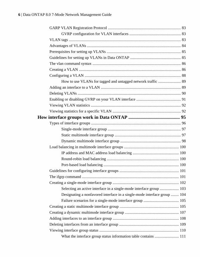
The e0M interfaceSome storage system models have an interface named e0M. The e0M interface is dedicated to DataONTAP management activities. It enables you to separate management traffic from data traffic onyour storage system for security and throughput benefits.
On a storage system that has the e0M interface, the Ethernet port (indicated by a wrench icon on therear of the chassis) connects to an internal Ethernet switch. The internal Ethernet switch providesconnectivity to the e0M interface and the remote management device such as the RLM or the BMC.The following diagram illustrates the connections.
When you set up a system that includes the e0M interface, the Data ONTAP setup scriptrecommends that you use the e0M as the preferred management interface for environments that usededicated LANs to isolate management traffic from data traffic. The setup script then prompts you toconfigure e0M. The e0M configuration is separate from the configuration of the remote managementdevice. Both configurations require unique IP addresses to allow the Ethernet switch to direct trafficto either the e0M interface or the remote management device. For information about how to set upthe e0M interface, see the Data ONTAP 7-Mode Software Setup Guide.
The e0M interface does not support interface groups, VLANs, and jumbo frames.
After you have set up the e0M interface, you can use it to access the storage system with thefollowing protocols, if they have been enabled:
• Telnet• RSH• HTTP or HTTPS• SSH
24 | Data ONTAP 8.0 7-Mode Network Management Guide

• SNMP
How to use the RLM or BMC to manage Data ONTAPremotely
You can manage your storage system locally from an Ethernet connection by using any networkinterface. However, to manage your storage system remotely, the system should have a Remote LANModule (RLM) or Baseboard Management Controller (BMC). These provide remote platformmanagement capabilities, including remote access, monitoring, troubleshooting, and alerting features.
If your data center configuration has management traffic and data traffic on separate networks, youcan configure the RLM or the BMC on the management network.
With the RLM, you can remotely access the storage system in the following ways:
• Through the serial consoleThe RLM is directly connected to the storage system through the serial console. You use the DataONTAP CLI to administer the storage system and the RLM.
• Through an Ethernet connection using a secure shell client applicationYou use the RLM CLI to monitor and troubleshoot the storage system.
With the BMC, you can access the storage system in the following ways:
• Through the serial consoleYou use the Data ONTAP CLI to administer the storage system and the BMC.
• Through an Ethernet connection by using a secure shell client applicationYou use the BMC CLI to monitor and troubleshoot the storage system.
For more information about the RLM and the BMC, see the Data ONTAP 7-Mode SystemAdministration Guide.
Next topics
Ways to configure the RLM on page 25
Ways to configure the BMC on page 26
Ways to configure the RLMBefore using the RLM, you must configure it for your storage system and network. You canconfigure the RLM when setting up a new storage system with RLM already installed, after settingup a new storage system with RLM already installed, or when adding an RLM to an existing storagesystem.
You can configure the RLM by using one of the following methods:
• Initializing a storage system that has the RLM pre-installed
Network interfaces on your storage system | 25

When the storage system setup process is complete, the rlm setup command runsautomatically. For more information about the entire setup process, see the Data ONTAP 7-ModeSoftware Setup Guide.
• Running the Data ONTAP setup scriptThe setup script ends by initiating the rlm setup command.
• Running the Data ONTAP rlm setup commandFor information about using the rlm setup command to configure the RLM, see the DataONTAP 7-Mode System Administration Guide.
When the rlm setup script is initiated, you are prompted to enter network and mail hostinformation.
Ways to configure the BMCBefore using the BMC, you must configure it for your storage system and network. You canconfigure the BMC when setting up a new storage system with BMC already installed or after settingup a new storage system with BMC already installed.
You can configure the BMC by using one of the following methods:
• Initializing a storage system that has the BMCWhen the storage system setup process is complete, the bmc setup command runsautomatically. For more information about the entire setup process, see the Data ONTAP 7-ModeSoftware Setup Guide.
• Running the Data ONTAP setup scriptThe setup script ends by initiating the bmc setup command.
• Running the Data ONTAP bmc setup commandFor information about using the bmc setup command to configure the BMC, see the DataONTAP 7-Mode System Administration Guide.
When the bmc setup script is initiated, you are prompted to enter network and mail hostinformation.
How TSO increases outbound throughputTCP Segmentation Offload (TSO), or Large Send Offload (LSO), is a technique for reducing theCPU usage of the host system in high-bandwidth outbound network connections. In TSO, datasegmentation is offloaded to the NIC that divides the data into the default maximum transmissionunit (MTU) size of the outgoing interface.
When a large amount of data is transmitted to a destination system, TCP in the host system segmentsthe data into MTU sized packets. For each segment , a header buffer is allocated and a TCP header isinserted. The packets are sent down through the layers of the TCP stack, and each layer adds its ownheader to the packet. Processing all the created segments at each layer in the protocol stack canburden the CPU of the controller. This leads to the wastage of CPU cycles in the host system and
26 | Data ONTAP 8.0 7-Mode Network Management Guide

causes an overhead to the host CPU. However, using TSO, this overhead can be passed down to theNIC to improve CPU efficiency of the host.
Next topics
Data ONTAP support for TSO on page 27
Viewing the TSO statistics on page 27
Data ONTAP support for TSOStarting with Data ONTAP 8.0.1, TSO is supported on all Data ONTAP versions. By default, TSO isenabled on all the network interfaces on the storage system. TSO is also enabled on VLANs and anytype of interface groups if the underlying network interfaces support TSO.
TSO is automatically disabled under the following conditions:
• In any type of interface group, if any of the constituent network interfaces do not support TSO• In rate-limited connections such as SnapMirror with the throttle option enabled
For more information about the replication.throttle.enable option, see the options(1)man page.
Viewing the TSO statisticsViewing the TSO statistics enables you to find out whether TSO is functioning and gives you anestimate of the saved CPU cycles.
Step
1. To view the TSO statistics, enter the following command:
netstat -p tcp
Example
The example shows a part of the netstat -p tcp command output.
49759833 segments sent using TSO1637084830596 bytes sent using TSO0 TSO segments truncated0 TSO wrapped sequence space segments
The netstat -p tcp counters related to TSO are listed in the order of appearance in theoutput.
• Segments sent using TSOThis counter indicates the number of segments sent by the application before the NICperforms TSO.For example, when 64 KB of data is transmitted, the TSO segments counter is incrementedby 1.
Network interfaces on your storage system | 27

• Bytes sent using TSOThis counter indicates the number of bytes of segments sent by the application before theNIC performs TSO.For example, when 64 KB of data is transmitted, the TSO bytes counter is incremented by64 KB.
• TSO segments truncatedThis counter indicates the number of times a segment has to be truncated because anapplication sends a buffer that is larger than the maximum size of the packet transmitted byNIC.For example, if the NIC supports a maximum segment size of 48 KB and an applicationsends 64 KB, then the buffer breaks the larger segment in two TSO segments. The firstsegment is 48 KB and the second segment is 16 (64 - 48) KB. This ensures that the NICcard does not transmit a large buffer.
• TSO wrapped sequence space segmentsThis counter indicates the number of times a TSO segment wraps the 32-bit TCP sequencespace.
How Data ONTAP uses ACP to increase storage availabilityACP, or Alternate Control Path, is a protocol that enables Data ONTAP to manage and control a SASdisk shelf storage subsystem. It uses a separate network (alternate path) from the data path, somanagement communication is not dependent on the data path being intact and available.
You do not need to actively manage the SAS disk shelf storage subsystem. Data ONTAPautomatically monitors and manages the subsystem without operator intervention. However, youmust provide the required physical connectivity and configuration parameters to enable the ACPfunctionality.
Note: You can install SAS disk shelves without configuring ACP. However, for maximum storageavailability and stability, you should always have ACP configured and enabled.
After you enable ACP, you can use the storage show acp and acpadmin list all commandsto display information about your ACP subsystem.
Because ACP communication is on a separate network, it does not affect data access in any way.
Next topics
Enabling ACP on page 29
The ACP subnet on page 30
28 | Data ONTAP 8.0 7-Mode Network Management Guide

Enabling ACPACP can increase your storage availability when you use SAS disk shelves. To get the benefits ofACP, you must configure and enable ACP on your storage system.
Before you begin
ACP must be cabled before beginning this procedure. For more information, see the Installation andService Guide for your disk shelf.
If you have not previously configured the network connectivity for ACP, and your platform does nothave a dedicated ACP port, you must gather the following network configuration information for theACP connection:
• Network interfaceAn unused network interface you want to use for ACP traffic (unless your storage system has adedicated ACP port)
• Domain for network interfaceThe network name (an IP address ending in 0) for the private subnet to be used exclusively byACP (if you do not choose to use the default value)
• Netmask for network interfaceThe network mask for the ACP subnet (if you do not want to use the default value)
Step
1. At the Data ONTAP command line, enter the following command:
acpadmin configure
If you have not previously configured the networking information for ACP, you are prompted forthat information.
Example
For example, if you select e0b as the interface for ACP traffic, 198.15.1.0 as the ACP domain,and 255.255.255.0 as the network mask for the ACP subnet, the storage show acpcommand output looks similar to the following example:
my-sys-1> storage show acp
Alternate Control Path: enabled Ethernet Interface: e0b ACP Status: Active ACP IP address: 198.15.1.212 ACP domain: 198.15.1.0 ACP netmask: 255.255.255.0 ACP Connectivity Status: Partial Connectivity
Shelf Module Reset Cnt IP address FW Version Status---------------------------------------------------------------------
Network interfaces on your storage system | 29

7a.001.A 002 198.15.1.145 01.05 active7a.001.B 003 198.15.1.146 01.05 active7c.002.A 000 198.15.1.206 01.05 active7c.002.B 001 198.15.1.204 01.05 active
After you finish
If you want to change your ACP configuration parameters later, you can use the acpadminconfigure command to do so.
The ACP subnetThe ACP subnet is a private Ethernet network that enables the ACP processor in the SAS module tocommunicate both with Data ONTAP and with the SAS IOMs in the disk shelves.
The ACP subnet is separate from the I/O data path that connects the disk shelves to the HBA on thestorage controller. When you configure ACP on one of the system's network interfaces, you mustsupply a private domain name that conforms to the standard for private internet addresses(RFC1918). You can use the system default domain, 198.15.1.0, or another network name (that is, anIP address ending in 0) that conforms to the standard.
If you are configuring ACP for disk shelves attached to an HA pair, you must supply the same ACPdomain name and network mask for both systems.
Attention: Do not connect the ACP port to a routed network, and do not configure switches orhubs between the ACP port and the designated Ethernet port. Doing so is not supported and causesinterruptions in service.
After you select a domain name and network mask for the interface, Data ONTAP automaticallyassigns IP addresses for the ACP interface on the storage controller and both I/O modules on eachdisk shelf on the ACP subnet.
You can use the sysconfig -v command to check whether your ACP subnet is cabled correctly. IfACP is disabled, sysconfig shows ACP connectivity as "NA".
30 | Data ONTAP 8.0 7-Mode Network Management Guide

Standards and characteristics of Ethernet frames
Frame size and Maximum Transmission Unit (MTU) size are the two important characteristics of anEthernet frame. The standard Ethernet (IEEE 802.3) frame size is 1,518 bytes. The MTU sizespecifies the maximum number of bytes of data that can be encapsulated in an Ethernet frame.
The frame size of a standard Ethernet frame (defined by RFC 894) is the sum of the Ethernet header(14 bytes), the payload (IP packet, usually 1,500 bytes), and the Frame Check Sequence (FCS) field(4 bytes). You can change the default frame size on Gigabit Ethernet network interfaces.
The MTU size specifies the maximum payload that can be encapsulated in an Ethernet frame. Forexample, the MTU size of a standard Ethernet frame is 1,500 bytes; this is the default for storagesystems. However, a jumbo frame, with an MTU size of 9,000 bytes, can also be configured.
Next topics
What jumbo frames are on page 31
Flow control on page 32
What jumbo frames areJumbo frames are larger than standard frames and require fewer frames. Therefore, you can reducethe CPU processing overhead by using jumbo frames with your network interfaces. Particularly, byusing jumbo frames with a Gigabit or 10 Gigabit Ethernet infrastructure, you can significantlyimprove performance, depending on the network traffic.
Jumbo frames are packets that are longer than the standard Ethernet (IEEE 802.3) frame size of 1,518bytes. The frame size definition for jumbo frames is vendor-specific because jumbo frames are notpart of the IEEE standard. The most commonly used jumbo frame size is 9,018 bytes.
Jumbo frames can be used for all Gigabit and 10 Gigabit Ethernet interfaces that are supported onyour storage system. The interfaces must be operating at or above 1,000 Mbps.
You can set up jumbo frames on your storage system in the following two ways:
• During initial setup, the setup command prompts you to configure jumbo frames if you have aninterface that supports jumbo frames on your storage system.
• If your system is already running, you can enable jumbo frames by setting the MTU size on aninterface.
Next topics
Network interface requirements for jumbo frames on page 32
Guidelines to configure clients for jumbo frames on page 32
Standards and characteristics of Ethernet frames | 31
Network interface requirements for jumbo framesBefore you enable jumbo frames on your storage system, jumbo frames must be enabled for theswitch ports, client interfaces, and intermediate routers on the network. If your storage system andthe client are on different subnets, the next-hop router must be configured for jumbo frames.
Guidelines to configure clients for jumbo framesWhen configuring clients for jumbo frames, you should verify certain configurations, such as theTCP window size of the client and the MTU size of the client, storage system, and any intermediatesubnet.
The guidelines for configuring clients for jumbo frames are as follows:
• Configure jumbo frames on the client and on your storage system.Find how to configure jumbo frames on your client by checking the network adapterdocumentation for your client.
• Enlarge the client's TCP window size.The minimum value for the client's window size should be two times the MTU size, minus 40,and the maximum value can be the highest value your system allows. Typically, the maximumvalue you can set for your client's TCP window is 65,535. If your storage system is configured tosupport jumbo frames and the client is not, the communication between the storage system andthe client occurs at the client's frame size.
• Configure the storage system and UDP clients to have the same MTU size.User Datagram Protocol (UDP) systems do not negotiate the MTU size. If your storage systemand clients do not have the same MTU size, the storage system might send packets that the clientscannot receive.
• Check the MTU size of any intermediate subnets if your storage system and the client are ondifferent subnets.If the storage system and the client (both configured to use jumbo frames) are on different subnetsand an intermediate subnet does not support jumbo frames, the intermediate router fragments theIP packets and the advantages of using jumbo frames are lost.
Related tasks
Specifying an MTU size for a network interface on page 36
Flow controlFlow control enables you to manage the flow of frames between two directly connected link-partners.Flow control can reduce or eliminate dropped packets due to overrun.
To achieve flow control, you can specify a flow control option that causes packets called Pauseframes to be used as needed. For example, link-partner A sends a Pause On frame to link-partner Bwhen its receive buffers are nearly full. Link-partner B suspends transmission until it receives aPause Off frame from link-partner A or a specified timeout threshold is reached.
32 | Data ONTAP 8.0 7-Mode Network Management Guide

Network interface configuration
Configuring network interfaces involves assigning IP addresses, setting network parameters andhardware-dependent values, specifying network interfaces, and viewing your storage system'snetwork configuration.
When you configure network interfaces, you can do any or all of the following:
• Assign an IP address to a network interface.• Set parameters such as network mask, broadcast address.• Set hardware-dependent values such as media type, MTU size, and flow control.• Specify whether the interface should be attached to a network with firewall security protection.• Specify whether the network interface must be registered with Windows Internet Name Services
(WINS), if CIFS is running and at least one WINS server has been configured.• Specify the IP address of an interface or specify the interface name on an HA pair partner for
takeover mode.• View the current configuration of a specific interface or all interfaces that exist on your storage
system.
Next topics
Configuring network interfaces on page 33
Creating or removing aliases on page 41
Changing the status of an interface on page 42
Viewing or modifying interface settings with FilerView on page 42
Blocking or unblocking protocols from network interfaces on page 43
Network interface information you can view on page 44
Related concepts
Network interfaces on your storage system on page 21
Configuring network interfacesYou can configure network interfaces either during system setup or when the storage system isoperating. When the storage system is operating, you can use the ifconfig command to assign ormodify configuration values of your network interfaces.
During system setup, you can configure the IP addresses for the network interfaces. An ifconfigcommand is included in the /etc/rc file of the root volume for each network interface that youconfigured during the system setup. After your storage system has been set up, the ifconfigcommands in the /etc/rc file are used to configure the network interfaces on subsequent storagesystem reboots.
Network interface configuration | 33

You can use the ifconfig command to change values of parameters for a network interface whenyour storage system is operating. However, such changes are not automatically included in the /etc/rc file. If you want your configuration modifications to be persistent after a reboot, you mustinclude the ifconfig command values in the /etc/rc file.
Next topics
Configuring an IP address for a network interface on page 34
Specifying a subnet mask for a network interface on page 35
Specifying a broadcast address on page 35
Specifying a media type for a network interface on page 36
Specifying an MTU size for a network interface on page 36
Specifying the flow control type for a network interface on page 37
Specifying whether a network interface is trusted on page 37
Configuring a partner interface in an HA pair on page 38
Enabling or disabling automatic takeover for a network interface on page 39
Removing a primary IP address from a network interface on page 40
Viewing network interface settings on page 41
Configuring an IP address for a network interfaceYou can configure IP addresses for your network interface during system setup. To configure the IPaddresses later, you should use the ifconfig command.
About this task
• Network configuration changes made by using the ifconfig command are not automaticallyincluded in the /etc/rc file. To make the configuration changes persistent after reboots, includethe ifconfig command in the /etc/rc file.
• When you configure an IP address, your storage system creates a network mask based on theclass of the address (Class A, B, C, or D) by default.
Step
1. To configure an IP address for a network interface, enter the following command:
ifconfig interface_name IP_address
interface_name is the name of the network interface.
IP_address is the IP address that you want to assign to the network interface.
Example
To configure a quad-port Ethernet interface e3a to use the IPv4 address 192.0.2.10, enter thefollowing command:
ifconfig e3a 192.0.2.10
34 | Data ONTAP 8.0 7-Mode Network Management Guide

Related tasks
Specifying a subnet mask for a network interface on page 35
Specifying a subnet mask for a network interfaceYou must specify a subnet mask if you have created subnets that do not match the class boundary ofthe IPv4 address of the network interface. You can specify a subnet mask for a network interface byusing the ifconfig command.
About this task
Data ONTAP allows you to configure a 32-bit subnet mask with all bits equal to 1.
Step
1. To specify a subnet mask, enter the following command:
ifconfig interface_name netmask mask
interface_name is the name of the network interface.
mask is the subnet mask.
ExampleTo configure a 24-bit mask for the interface e3a that you have already configured, enter thefollowing command:
ifconfig e3a netmask 255.255.255.0
Related tasks
Configuring an IP address for a network interface on page 34
Specifying a broadcast addressYou can use a broadcast address to send a message to all the machines on a subnet. You can specify abroadcast address by using the ifconfig command.
Step
1. To specify a broadcast address, enter the following command:
ifconfig interface_name broadcast address
interface_name is the name of the network interface.
address is the broadcast address.
ExampleTo set a broadcast address of 192.0.2.25 for the network 192.0.2.10 with subnet mask255.255.255.0, enter the following command:
ifconfig e3a broadcast 192.0.2.25
Network interface configuration | 35

Specifying a media type for a network interfaceYou can specify a media type for configuring the speed and duplex of a network interface by usingthe ifconfig command.
Step
1. To specify a media type, enter the following command:
ifconfig interface_name mediatype type
interface_name is the name of the network interface.
type specifies the Ethernet media type used. The possible values are tp, tp-fd, 100tx, 100tx-fd, auto, or 10g-sr.
For more information, see the na_ifconfig(1) man page.
ExampleTo configure the interface e2a as a 100Base-TX full-duplex interface, enter the followingcommand:
ifconfig e2a mediatype 100tx-fd
Specifying an MTU size for a network interfaceThe maximum transmission unit (MTU) size is used to specify the jumbo frame size on GigabitEthernet interfaces. You can specify the MTU size for transmission between your storage system andits client by using the ifconfig command.
Step
1. To specify an MTU size, enter the following command:
ifconfig interface_name mtusize size
interface_name is the name of the network interface.
size is the MTU to be used for the network interface.
ExampleTo specify an MTU size of 9000 for Gigabit Ethernet interface e8, enter the following command:
ifconfig e8 mtusize 9000
Related concepts
Standards and characteristics of Ethernet frames on page 31
What jumbo frames are on page 31
Guidelines to configure clients for jumbo frames on page 32
36 | Data ONTAP 8.0 7-Mode Network Management Guide

Specifying the flow control type for a network interfaceYou can specify the flow control type for a network interface to manage the flow of frames betweentwo directly connected link-partners by using the ifconfig command. You can configure flowcontrol on interfaces operating at or above 1,000 Mbps.
About this task
The configured flow control setting is advertised during autonegotiation. If autonegotiation succeeds,the operational flow control setting is determined based on the negotiated speed and the valueadvertised by the other device. If autonegotiation fails, the configured flow control setting is used.
You can also use the ifstat command to view the operational flow control setting.
Step
1. To specify the flow control type, enter the following command:
ifconfig interface_name flowcontrol value
interface_name is the name of the network interface.
value is the flow control type. You can specify the following values for the flowcontroloption:
none No flow control
receive Able to receive flow control frames
send Able to send flow control frames
full Able to send and receive flow control frames
The default flow control type is full.
ExampleTo turn off flow control on interface e8, enter the following command:
ifconfig e8 flowcontrol none
Related concepts
Flow control on page 32
Specifying whether a network interface is trustedYou can specify whether a network interface is trustworthy or untrustworthy. When you specify aninterface as untrusted (untrustworthy), any packets received on the interface are likely to be dropped.
Network interface configuration | 37
For example, if you run a ping command on an untrusted interface, the interface drops any ICMPresponse packet received.
About this task
Applications such as NFS, CIFS, HTTP can choose to accept packets only from trusted interfaces. Ifthe destination interface is set as untrusted, it can receive packets from untrusted interfaces.Otherwise, the packets from untrusted interfaces are dropped. By default, only HTTP allowsreceiving packets from untrusted interfaces.
Step
1. To specify a network interface as trusted or untrusted, enter the following command:
ifconfig interface_name {trusted|untrusted}
interface_name is the name of the network interface.
trusted specifies that the network interface is to be trusted.
untrusted specifies that the network interface is not to be trusted.
ExampleTo specify that the network attached to interface e8 is not to be trusted for firewall security, enterthe following command:
ifconfig e8 untrusted
Configuring a partner interface in an HA pairTo prepare for a successful takeover in an HA configuration, you can map a network interface to anIP address or to another network interface on the partner node. During a takeover, the networkinterface on the surviving node assumes the identity of the partner interface.
Before you begin
When specifying the partner IP address, you must ensure that both the local network interface and thepartner’s network interface are attached to the same network segment or network switch.
About this task
• If the network interface is an interface group, the partner interface must be denoted by aninterface name and not an IP address.The partner interface can be an interface group or a physical network interface.
• You cannot specify the underlying physical ports of an interface group in a partner configuration.• For the partner configuration to be persistent across reboots, you must include the ifconfig
command in the /etc/rc file.For a successful takeover in both directions, you must repeat the partner configuration in the /etc/rc files of each node.
38 | Data ONTAP 8.0 7-Mode Network Management Guide

• When specifying the partner interface name, you can configure the interfaces symmetrically, forexample map interface e1 on one node to interface e1 on the partner node.Though symmetrical configuration is not mandatory, it simplifies administration andtroubleshooting tasks.
Step
1. Depending on the partner configuration that you want to specify, enter the following command:
If you want specify a Enter the following command...
Partner IP address ifconfig interface_name partner address
interface_name is the name of the network interface.
address is the partner IP address.
Partner interface name ifconfig interface_name partner partner_interface
partner_interface is the name of the partner network interface.
Example: Specifying a partner IP address and partner interface name
Consider node1 and node2 are two storage systems in an HA configuration
If the IP address of the interface e8 on node2 is 198.9.200.38, the following command allowsthe interface e1 of node1 to take over the IP address of node2 for the duration of the takeover:
node1> ifconfig e1 partner 198.9.200.38
Instead of specifying the IP address, you can also specify the partner interface name. Thefollowing command allows the interface e1 of node1 to assume the identity of e8 of node2 forthe duration of the takeover:
node1> ifconfig e1 partner e8
Enabling or disabling automatic takeover for a network interfaceYou can enable or disable negotiated failover for a network interface to trigger automatic takeover ifthe interface experiences a persistent failure. You can use the nfo option of the ifconfig commandto enable or disable negotiated failover.
About this task
• You must include the nfo option in the /etc/rc file for it to persist across reboots.• You can specify the nfo option for an interface group. However, you cannot specify the nfo
option for any underlying physical interface of the interface group.
Network interface configuration | 39

Steps
1. To enable takeover on interface failures, enter the following command:
options cf.takeover.on_network_interface_failure on
2. To enable or disable negotiated failover, enter the following command:
ifconfig interface_name {nfo|-nfo}
interface_name is the name of the network interface.
nfo—Enables negotiated failover
-nfo—Disables negotiated failover
ExampleTo enable negotiated failover on the interface e8 of an HA pair, enter the following command:
ifconfig e8 nfo
Removing a primary IP address from a network interfaceYou can remove a primary IP address from a network interface to disconnect the network interfacefrom the network or reconfigure the network interface.
Before you begin
Ensure that you remove all the manually configured alias addresses for the interface.
Step
1. To remove a primary IP address, enter the following command:
ifconfig interface_name 0
interface_name is the name of the network interface.
Alternatively, to remove a primary IPv4 address, you can use the following command:
ifconfig interface_name 0.0.0.0
Example
To remove the primary address of the interface e3, enter the following command:
ifconfig e3 0
Related tasks
Creating or removing aliases on page 41
40 | Data ONTAP 8.0 7-Mode Network Management Guide
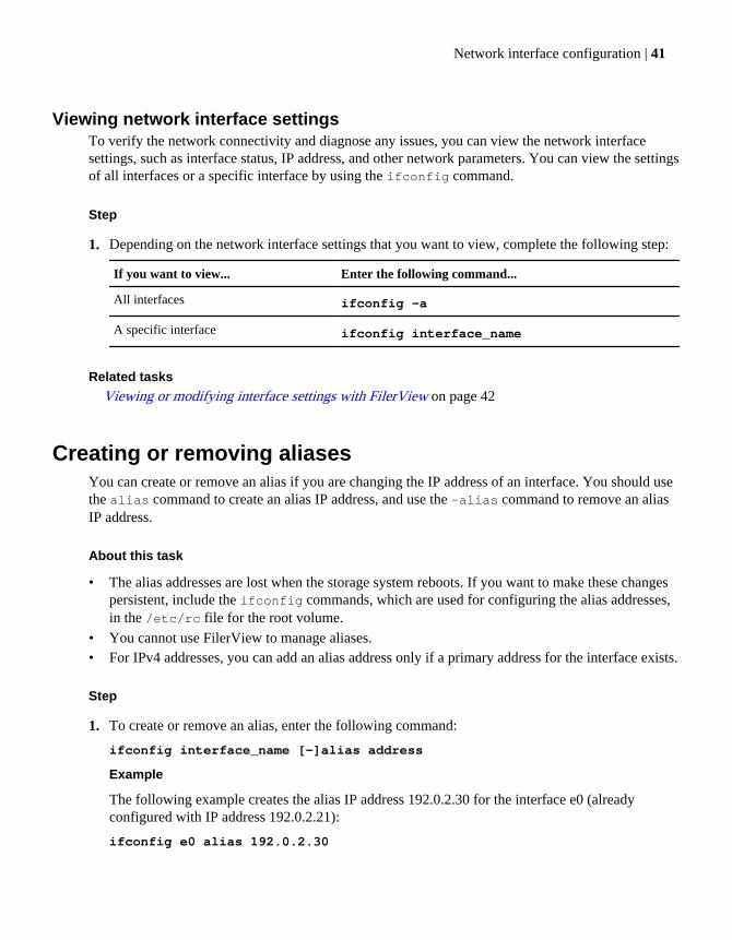
Viewing network interface settingsTo verify the network connectivity and diagnose any issues, you can view the network interfacesettings, such as interface status, IP address, and other network parameters. You can view the settingsof all interfaces or a specific interface by using the ifconfig command.
Step
1. Depending on the network interface settings that you want to view, complete the following step:
If you want to view... Enter the following command...
All interfaces ifconfig -a
A specific interface ifconfig interface_name
Related tasks
Viewing or modifying interface settings with FilerView on page 42
Creating or removing aliasesYou can create or remove an alias if you are changing the IP address of an interface. You should usethe alias command to create an alias IP address, and use the -alias command to remove an aliasIP address.
About this task
• The alias addresses are lost when the storage system reboots. If you want to make these changespersistent, include the ifconfig commands, which are used for configuring the alias addresses,in the /etc/rc file for the root volume.
• You cannot use FilerView to manage aliases.• For IPv4 addresses, you can add an alias address only if a primary address for the interface exists.
Step
1. To create or remove an alias, enter the following command:
ifconfig interface_name [-]alias address
Example
The following example creates the alias IP address 192.0.2.30 for the interface e0 (alreadyconfigured with IP address 192.0.2.21):
ifconfig e0 alias 192.0.2.30
Network interface configuration | 41

The following example removes the 192.0.2.30 alias for the interface e0 specified in the previousexample:
ifconfig e0 -alias 192.0.2.30
Changing the status of an interfaceYou must make an interface inactive before performing tasks such as upgrading an interface,disabling a failed interface, or troubleshooting connectivity issues. You must again make theinterface active after you complete the task. You can make an interface active or inactive by usingthe ifconfig command.
Step
1. To change the status of an interface, enter the following command:
ifconfig interface {up|down}
up—makes the interface active
down—makes the interface inactive
Viewing or modifying interface settings with FilerViewYou can use FilerView to view or modify the settings of all interfaces or a specific interface. Thechanges made by using FilerView are automatically written to the /etc/rc file.
Steps
1. From the list on the left pane, click Network > Manage Interfaces.
2. Depending on whether you want to view or modify the configuration settings, perform thefollowing step:
If you want to... Then...
View interface configuration details Click Show All Interface Details.
Modify an interface configuration Select an interface and click Modify.
42 | Data ONTAP 8.0 7-Mode Network Management Guide

Blocking or unblocking protocols from network interfacesYou can use the interface.blocked.protocol option to block specified network protocols,including CIFS, iSCSI, FTP, or NFS, on selected network interfaces. You can also unblock aprotocol from a network interface.
Step
1. To block or unblock protocols from network interfaces, perform one of the following steps:
If you want to... Enter the following command...
Block a protocol frommultiple network interfaces
optionsinterface.blocked.protocol_name interface_name,interface_name, ...interface_name
protocol_name is the protocol that you want to block.
interface_name is the interface on which you want to block theprotocol.
Note: To block multiple protocols from a single interface, you mustrepeat the command for each protocol.
Unblock a protocol options interface.blocked.protocol_name ""
Example
To block the interface e9 from using the CIFS protocol, enter the following command:
options interface.blocked.cifs e9
To block the CIFS protocol from the interfaces e0a and e0b, enter the following command:
options interface.blocked.cifs e0a,e0b
To block NFS, CIFS, and FTP from the interface e0a, enter the following commands:
options interface.blocked.nfs e0a
options interface.blocked.cifs e0a
options interface.blocked.ftpd e0a
To unblock CIFS from all the network interfaces, enter the following command:
options interface.blocked.cifs ""
Network interface configuration | 43
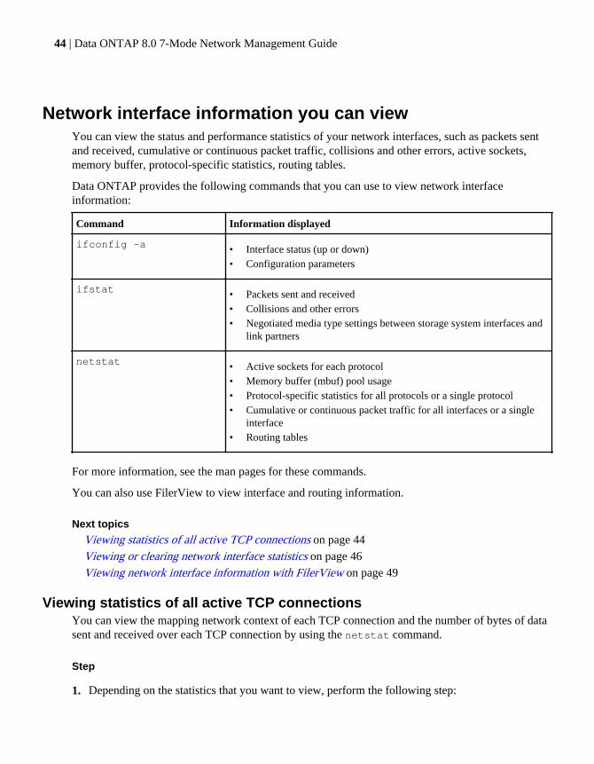
Network interface information you can viewYou can view the status and performance statistics of your network interfaces, such as packets sentand received, cumulative or continuous packet traffic, collisions and other errors, active sockets,memory buffer, protocol-specific statistics, routing tables.
Data ONTAP provides the following commands that you can use to view network interfaceinformation:
Command Information displayed
ifconfig -a • Interface status (up or down)• Configuration parameters
ifstat • Packets sent and received• Collisions and other errors• Negotiated media type settings between storage system interfaces and
link partners
netstat • Active sockets for each protocol• Memory buffer (mbuf) pool usage• Protocol-specific statistics for all protocols or a single protocol• Cumulative or continuous packet traffic for all interfaces or a single
interface• Routing tables
For more information, see the man pages for these commands.
You can also use FilerView to view interface and routing information.
Next topics
Viewing statistics of all active TCP connections on page 44
Viewing or clearing network interface statistics on page 46
Viewing network interface information with FilerView on page 49
Viewing statistics of all active TCP connectionsYou can view the mapping network context of each TCP connection and the number of bytes of datasent and received over each TCP connection by using the netstat command.
Step
1. Depending on the statistics that you want to view, perform the following step:
44 | Data ONTAP 8.0 7-Mode Network Management Guide
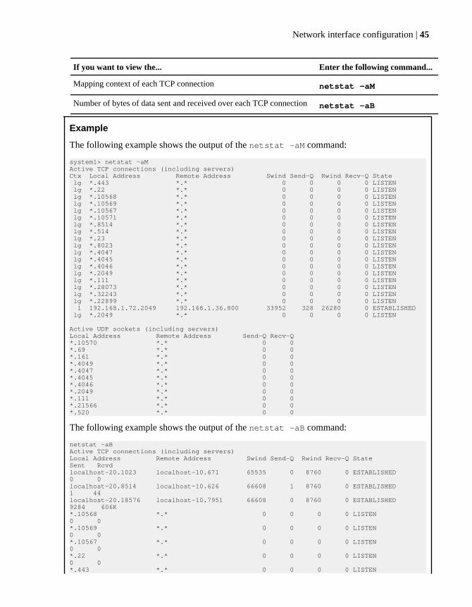
If you want to view the... Enter the following command...
Mapping context of each TCP connection netstat -aM
Number of bytes of data sent and received over each TCP connection netstat -aB
Example
The following example shows the output of the netstat -aM command:
system1> netstat -aMActive TCP connections (including servers)Ctx Local Address Remote Address Swind Send-Q Rwind Recv-Q State lg *.443 *.* 0 0 0 0 LISTEN lg *.22 *.* 0 0 0 0 LISTEN lg *.10568 *.* 0 0 0 0 LISTEN lg *.10569 *.* 0 0 0 0 LISTEN lg *.10567 *.* 0 0 0 0 LISTEN lg *.10571 *.* 0 0 0 0 LISTEN lg *.8514 *.* 0 0 0 0 LISTEN lg *.514 *.* 0 0 0 0 LISTEN lg *.23 *.* 0 0 0 0 LISTEN lg *.8023 *.* 0 0 0 0 LISTEN lg *.4047 *.* 0 0 0 0 LISTEN lg *.4045 *.* 0 0 0 0 LISTEN lg *.4046 *.* 0 0 0 0 LISTEN lg *.2049 *.* 0 0 0 0 LISTEN lg *.111 *.* 0 0 0 0 LISTEN lg *.28073 *.* 0 0 0 0 LISTEN lg *.32243 *.* 0 0 0 0 LISTEN lg *.22899 *.* 0 0 0 0 LISTEN 1 192.168.1.72.2049 192.168.1.36.800 33952 328 26280 0 ESTABLISHED lg *.2049 *.* 0 0 0 0 LISTEN
Active UDP sockets (including servers)Local Address Remote Address Send-Q Recv-Q*.10570 *.* 0 0*.69 *.* 0 0*.161 *.* 0 0*.4049 *.* 0 0*.4047 *.* 0 0*.4045 *.* 0 0*.4046 *.* 0 0*.2049 *.* 0 0*.111 *.* 0 0*.21566 *.* 0 0*.520 *.* 0 0
The following example shows the output of the netstat -aB command:
netstat -aBActive TCP connections (including servers)Local Address Remote Address Swind Send-Q Rwind Recv-Q State Sent Rcvdlocalhost-20.1023 localhost-10.671 65535 0 8760 0 ESTABLISHED 0 0 localhost-20.8514 localhost-10.626 66608 1 8760 0 ESTABLISHED 1 44 localhost-20.18576 localhost-10.7951 66608 0 8760 0 ESTABLISHED 9284 606K *.10568 *.* 0 0 0 0 LISTEN 0 0 *.10569 *.* 0 0 0 0 LISTEN 0 0 *.10567 *.* 0 0 0 0 LISTEN 0 0 *.22 *.* 0 0 0 0 LISTEN 0 0 *.443 *.* 0 0 0 0 LISTEN
Network interface configuration | 45

0 0 *.8514 *.* 0 0 0 0 LISTEN 0 0 *.514 *.* 0 0 0 0 LISTEN 0 0 *.23 *.* 0 0 0 0 LISTEN 0 0 *.8023 *.* 0 0 0 0 LISTEN 0 0 *.32243 *.* 0 0 0 0 LISTEN 0 0 *.22899 *.* 0 0 0 0 LISTEN 0 0
Active UDP sockets (including servers)Local Address Remote Address Send-Q Recv-Q*.10570 *.* 0 0*.69 *.* 0 0*.161 *.* 0 0
Viewing or clearing network interface statisticsYou can use the ifstat command to view the cumulative statistics of packets received and sent on aspecified interface or on all interfaces. You can also use the ifstat command to clear the statistics.
About this task
• The ifstat command displays the cumulative network interface statistics that are gatheredeither from the time of the last reboot or from the last time you cleared them.
• If you use the ifstat command on a storage system that is part of an HA pair, the resultinginformation pertains only to the storage system on which the command was run. The informationdoes not include statistics for the partner node in an HA pair.
• In an HA pair in takeover mode, the ifstat command displays the combined statistics of thepackets processed by the network interface on the local node and those on the partner node.Because the statistics displayed by the ifstat command are cumulative, a giveback does notcause the statistics to zero out.
Step
1. Depending on the statistics that you want to view, perform the following step:
If you want to... Enter the following command...
View the network interface statistics of allinterfaces
ifstat -a
View the network interface statistics of a specificinterface
ifstat interface_name
interface_name is the name of the networkinterface.
Clear the network interface statistics of a networkinterface
ifstat -z interface_name
46 | Data ONTAP 8.0 7-Mode Network Management Guide

The output of the ifstat command depends on the type of interface. For example, Ethernet orGigabit Ethernet interfaces generate different types of statistics.
Example of showing the network interface statistics before and after clearingthem
To view the statistics of the network interface e0a, enter the following command:
ifstat e0a
An output similar to the following is displayed.
system1> ifstat e0a
-- interface e0a (8 days, 20 hours, 10 minutes, 27 seconds) --
RECEIVE Frames/second: 13 | Bytes/second: 800 | Errors/minute: 0 Discards/minute: 0 | Total frames: 897k | Total bytes: 62415k Total errors: 0 | Total discards: 0 | Multi/broadcast: 734k No buffers: 0 | Non-primary u/c: 0 | Tag drop: 0 Vlan tag drop: 0 | Vlan untag drop: 0 | CRC errors: 0 Runt frames: 0 | Fragment: 0 | Long frames: 0 Jabber: 0 | Alignment errors: 0 | Bus overruns: 0 Queue overflows: 0 | Xon: 0 | Xoff: 0 Jumbo: 0 | Reset: 0 | Reset1: 0 Reset2: 0TRANSMIT Frames/second: 2 | Bytes/second: 110 | Errors/minute: 0 Discards/minute: 0 | Total frames: 153k | Total bytes: 24129k Total errors: 0 | Total discards: 0 | Multi/broadcast: 9478 Queue overflows: 0 | No buffers: 0 | Max collisions: 0 Single collision: 0 | Multi collisions: 0 | Late collisions: 0 Timeout: 0 | Xon: 0 | Xoff: 0 Jumbo: 0LINK_INFO Current state: up | Up to downs: 0 | Auto: on
Network interface configuration | 47

Speed: 1000m | Duplex: full | Flowcontrol: none
The following command clears and reinitializes the statistics for the network interface e0a:
ifstat -z e0a
The following sample output shows the network interface statistics for the network interfacee0a immediately after the statistics are cleared.
system1> ifstat e0a
-- interface e0a (0 hours, 0 minutes, 8 seconds) --
RECEIVE Frames/second: 1 | Bytes/second: 32 | Errors/minute: 0 Discards/minute: 0 | Total frames: 7 | Total bytes: 448 Total errors: 0 | Total discards: 0 | Multi/broadcast: 0 No buffers: 0 | Non-primary u/c: 0 | Tag drop: 0 Vlan tag drop: 0 | Vlan untag drop: 0 | CRC errors: 0 Runt frames: 0 | Fragment: 0 | Long frames: 0 Jabber: 0 | Alignment errors: 0 | Bus overruns: 0 Queue overflows: 0 | Xon: 0 | Xoff: 0 Jumbo: 0 | Reset: 0 | Reset1: 0 Reset2: 0TRANSMIT Frames/second: 1 | Bytes/second: 17 | Errors/minute: 0 Discards/minute: 0 | Total frames: 4 | Total bytes: 361 Total errors: 0 | Total discards: 0 | Multi/broadcast: 0 Queue overflows: 0 | No buffers: 0 | Max collisions: 0 Single collision: 0 | Multi collisions: 0 | Late collisions: 0 Timeout: 0 | Xon: 0 | Xoff: 0 Jumbo: 0LINK_INFO Current state: up | Up to downs: 0 | Auto: on
48 | Data ONTAP 8.0 7-Mode Network Management Guide
Speed: 1000m | Duplex: full | Flowcontrol: none
Related references
Statistics for Gigabit Ethernet controller VI, VII, and G20 interfaces on page 149
Statistics for the BGE 10/100/1000 Ethernet interface on page 156
Viewing network interface information with FilerViewYou can view network interface statistics, such as MTU size, incoming and outgoing packets on eachinterface, by using the Network Report in FilerView. You can also view routing informationincluding the routing tables by using the Network Report.
About this task
The Network Report in FilerView provides the same information that you get by running thenetstat -l, routed status, and netstat -rn commands.
Step
1. From the list on the left pane, click Network > Report.
The Network Report displays the interface statistics and routing tables.
Network interface configuration | 49


How routing in Data ONTAP works
You can have Data ONTAP route its own outbound packets to network interfaces. Although yourstorage system can have multiple network interfaces, it does not function as a router. However, it canroute its outbound packets.
Data ONTAP uses two routing mechanisms:
Fast path Data ONTAP uses this mechanism to route NFS packets over UDP and to route allTCP traffic.
Routing table To route IP traffic that does not use fast path, Data ONTAP uses the informationavailable in the local routing table. The routing table contains the routes that havebeen established and are currently in use, as well as the default route specification.
Next topics
What fast path is on page 51
How to manage the routing table on page 52
Specifying the default route on page 54
How to enable or disable routing mechanisms on page 55
How to view the routing table and default route information on page 57
Modifying the routing table on page 59
What fast path isFast path is an alternative routing mechanism to the routing table, in which the responses to incomingnetwork traffic are sent back by using the same interface as the incoming traffic. It providesadvantages such as load balancing between multiple network interfaces and improved storage systemperformance.
Fast path is enabled automatically on your storage system; however, you can disable it.
Using fast path provides the following advantages:
• Load balancing between multiple network interfaces on the same subnet.Load balancing is achieved by sending responses on the same interface of your storage systemthat receives the incoming requests.
• Increased storage system performance by skipping routing table lookups.
How fast path works with NFS-over-UDP
NFS-over-UDP traffic uses fast path only when sending a reply to a request. The reply packet is sentout on the same network interface that received the request packet.
How routing in Data ONTAP works | 51

For example, a storage system named toaster uses the toaster-e1 interface to send reply packets inresponse to NFS-over-UDP requests received on the toaster-e1 interface.
How fast path works with TCP
Data ONTAP can use fast path on every TCP packet transmitted except the first SYN packet (if DataONTAP initiates a connection). The network interface that is used to transmit a packet is the sameinterface that received the last packet.
For TCP connections, if Data ONTAP detects that using fast path in a network setup is not optimal,fast path is turned off automatically.
How fast path affects Telnet sessions and the ping utility
If fast path is enabled and the default router stops working, you cannot use the ping utility tocommunicate with your storage system. However, the Telnet sessions to your storage system can stillbe established from a non-local subnet. This happens because the ping utility uses routing tablelookups.
Fast path not compatible with asymmetric routing
If fast path is enabled on your storage system in an asymmetric network, the destination MACaddress of the response packet will be that of the router that forwarded the incoming packet.However, in asymmetric networks, the router that forwards packets to your storage system is not therouter that forwards packets sent by the storage system. In such scenarios, you must disable fast path.
Related tasks
Enabling or disabling fast path on page 55
How to manage the routing tableYou can manage the routing table automatically by using the routed daemon, or manually by usingthe route command.
Next topics
What the routed daemon does on page 53
When the routed daemon should be turned off on page 53
Routing tables in a vFiler unit environment on page 54
Circumstances that might alter the routing table on page 54
52 | Data ONTAP 8.0 7-Mode Network Management Guide

What the routed daemon doesThe routed daemon performs several functions automatically and can be configured to performseveral additional functions. The routed daemon is enabled by default.
The routed daemon performs the following functions by default:
• Deletes redirected routes after a specified period• Performs router discovery with ICMP Router Discovery Protocol (IRDP)
Router discovery is useful only if there is no static default route.• Listens for Routing Information Protocol (RIP) packets• Migrates routes to alternate interfaces when multiple interfaces are available on the same subnet
For example, the network interface e0a is on 10.1.1.2/24 and e0b is on 10.1.1.3/24. The defaultroute to 10.1.1.1 is through e0a. The subnet route 10.1.1.0/24 is also through e0a. Now if e0a isbrought to the down status, the routed daemon moves the default route to e0b and the subnetroute to e0b. Therefore, this function ensures continued connectivity to the local subnet andremote networks.
The routed daemon can also be configured to perform the following functions:
• Control RIP and IRDP behavior• Generate RIP response messages that update a host route on your storage system• Recognize distant gateways identified in the /etc/gateways file• Authenticate RIPv2 advertisements with Message Digest 5 (MD5) algorithm for improved
network security
For more information about the routed daemon, see the na_routed(1) man page.
When the routed daemon should be turned offIn some circumstances, you should turn off the routed daemon. For example, you should turn it offif you have multiple interfaces on the same subnet and you want to direct network traffic to specificinterfaces.
If you want to direct traffic to specific interfaces, you must turn off the routed daemon, because thedaemon sees all interfaces on a subnet as equivalent.
You can safely turn off the routed daemon if the following conditions are true:
• You do not use RIP or router discovery.• You have a single router per subnet or a network in which redirects are not sent.• You can manage your routing table directly.
Note: Unless you have specific routing needs and understand network routing configuration, youare advised to always keep the routed daemon on. Turning off the routed daemon might causeunexpected routing behavior.
How routing in Data ONTAP works | 53

Related tasks
Enabling or disabling the routed daemon from the command-line interface on page 56
Enabling or disabling the routed daemon with FilerView on page 56
Routing tables in a vFiler unit environmentIf you enable the MultiStore license and have more than one IPspace, Data ONTAP disables therouted daemon. Therefore, routing tables in such vFiler unit environments must be managedmanually with the route command.
The routed daemon runs only in the default IPspace. Data ONTAP does not support runningmultiple instances of the routed daemon in multiple IPspaces. Therefore, if you have multipleIPspaces, the routed daemon is automatically disabled.
All vFiler units in an IPspace share a routing table. Therefore, any commands that display ormanipulate the routing table apply to all vFiler units in that IPspace.
Circumstances that might alter the routing tableCertain events can cause the routing table to be modified. You should check the routing table afterthese events occur to be sure that it is still configured as required.
The routing table might be modified in the following circumstances:
• A new interface is configured with the ifconfig command and there are no existing entries forthe new network number in the routing table.
• You use the route add command to add an entry to the routing table.• Your storage system receives an ICMP redirect packet, which notifies the storage system of a
better first-hop router for a particular destination.
Note: Your storage system ignores ICMP redirect packets if theip.icmp_ignore_redirect.enable option is turned on.
• Your storage system is rebooted after the default route in the /etc/rc file is modified.
Specifying the default routeThe default route entry routes to destinations that are not listed in the routing table. You can specifythe default route in Data ONTAP either during initial setup or by modifying the /etc/rc file.
Steps
1. Open the /etc/rc file in the root volume by using a text editor.
2. Add the following command to the /etc/rc file:
route add default route_IP
route_IP is the IP address of the default route
54 | Data ONTAP 8.0 7-Mode Network Management Guide
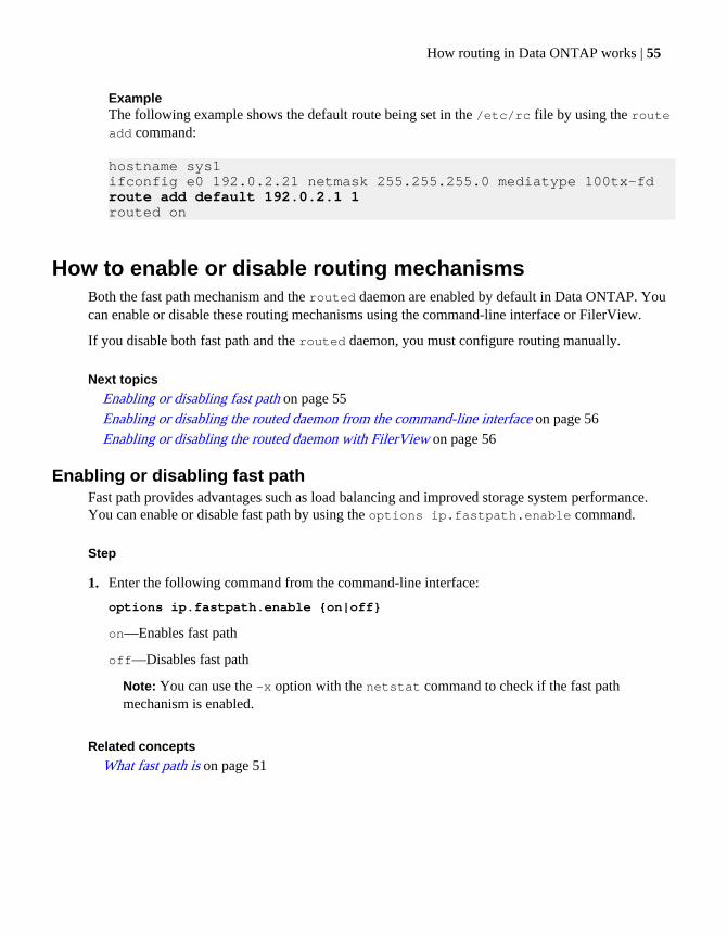
ExampleThe following example shows the default route being set in the /etc/rc file by using the routeadd command:
hostname sys1ifconfig e0 192.0.2.21 netmask 255.255.255.0 mediatype 100tx-fdroute add default 192.0.2.1 1routed on
How to enable or disable routing mechanismsBoth the fast path mechanism and the routed daemon are enabled by default in Data ONTAP. Youcan enable or disable these routing mechanisms using the command-line interface or FilerView.
If you disable both fast path and the routed daemon, you must configure routing manually.
Next topics
Enabling or disabling fast path on page 55
Enabling or disabling the routed daemon from the command-line interface on page 56
Enabling or disabling the routed daemon with FilerView on page 56
Enabling or disabling fast pathFast path provides advantages such as load balancing and improved storage system performance.You can enable or disable fast path by using the options ip.fastpath.enable command.
Step
1. Enter the following command from the command-line interface:
options ip.fastpath.enable {on|off}
on—Enables fast path
off—Disables fast path
Note: You can use the -x option with the netstat command to check if the fast pathmechanism is enabled.
Related concepts
What fast path is on page 51
How routing in Data ONTAP works | 55

Enabling or disabling the routed daemon from the command-line interfaceYou can manage the routing table automatically by using the routed daemon. You can turn on or turnoff the routed daemon by using the routed command.
About this task
You must add the routed command to the /etc/rc file for the routed daemon behavior to persistacross storage system reboots.
Step
1. To enable or disable the routed daemon, enter the following command:
routed {on|off}
on—Turns on the routed daemon
off—Turns off the routed daemon
Related concepts
What the routed daemon does on page 53
When the routed daemon should be turned off on page 53
Related references
The routed daemon on page 179
Enabling or disabling the routed daemon with FilerViewYou can use FilerView to turn on or turn off the routed daemon.
Steps
1. From the list on the left pane, click Network > Configure.
2. Select Yes (for on) or No (for off) from the Routed Enabled drop-down list.
3. Click Apply.
Related concepts
What the routed daemon does on page 53
When the routed daemon should be turned off on page 53
Related references
The routed daemon on page 179
56 | Data ONTAP 8.0 7-Mode Network Management Guide

How to view the routing table and default route informationYou can view the routing table of the storage system and default route information relating to yourroute's destinations, their gateways, how much each route is used, and the interface used by eachroute. Flags showing route status information are also displayed.
Next topics
Viewing the routing table from the command-line interface on page 57
Viewing the default route information from the command-line interface on page 58
Viewing the routing table and routing information by using FilerView on page 59
Viewing the routing table from the command-line interfaceYou can view information such as default route and the routes for specific destination addresses.
Step
1. To view the Data ONTAP routing table, enter one of the following commands:
• netstat -rn
• route -s
Example for interpreting the routing table
The output of the netstat -rn command is as follows:
netstat -rnRouting tables
Internet:Destination Gateway Flags Refs Use Interfacedefault 192.0.2.1 UGS 7 116009 e0a192.0.2/24 link#3 UC 0 0 e0a192.0.2.1 0:15:c6:bf:c6:44 UHL 1 0 e0a192.0.2.68 0:a0:98:7:66:2 UHL 0 1079 lo192.0.2.216 0:a0:98:7:3e:5 UHL 0 0 e0a192.0.2.217 0:a0:98:7:3e:5 UHL 0 0 e0a192.0.2.255 ff:ff:ff:ff:ff:ff UHL 0 9470 e0a127.0.0.1 127.0.0.1 UH 0 11 lo
In this example, the destination can be a host 192.0.2.1, a network 192.0.2/24, or the defaultroute. If the destination is a subnet on a network, the network number is followed by a forwardslash (/) and a number that describes the network mask for that network.
How routing in Data ONTAP works | 57

Routing table flags
The following table describes the Flags column in the netstat -rn output.
Flag Description
U Up—Route is valid
G Gateway—Route is to a gateway router rather than to a directly connected network or host
H Host name—Route is to a host rather than to a network, where the destination address is a completeaddress
R Reject—Set by ARP when an entry expires (for example, the IP address could not be resolved into aMAC address)
D Dynamic—Route added by a route redirect or RIP (if routed is enabled)
M Modified—Route modified by a route redirect
C Cloning—A new route is cloned from this entry when it is used
L Link—Link-level information, such as the Ethernet MAC address, is present
S Static—Route added with the route command
Viewing the default route information from the command-line interfaceYou can view default route information such as whether the routed daemon is turned on or off,default route information, and routing protocols. You can view the default route information by usingthe routed status command.
Step
1. Enter the following command:
routed status
Note: You can also view the default route by using the netstat -rn or route -scommands.
ExampleThe output of the routed status command is as follows:
routed statusRIP snooping is onGateway Metric State Time Last Heardexample-gateway.com 1 ALIVE Wed Mar 18 13:58:56 IST 20090 free gateway entries, 1 used
In the routed status command output, metric is the route property that is used to determinethe preferred route. The route with the lowest metric is the preferred route. You should alwaysuse a metric greater than 0 when adding default routes.
58 | Data ONTAP 8.0 7-Mode Network Management Guide

Viewing the routing table and routing information by using FilerViewYou can view the routing table, routing information, and routing protocols by using FilerView. Youcan view information such as default route and the routes for specific destination addresses.
Step
1. From the list on the left pane, click Network > Report.
The Routing section of the Network Report shows the default route and protocols in effect, aswell as routing tables.
Modifying the routing tableYou might want to add or delete routes in your routing table depending on the changes in yournetwork. You can use the route command to modify the routing table. You cannot modify therouting table using FilerView.
Step
1. Depending on whether you want to add or delete a route from the routing table, perform thefollowing step:
If youwant to...
Enter the following command...
Add aroute
route add destination [gateway metric]
destination is the IP address or host name of the destination for which the route is beingadded or deleted.
gateway is the gateway for the specified destination.
metric indicates the number of hops to the destination. The value of metric shouldbe greater than zero when the route to the destination is through the gateway. The value ofmetric is zero when the destination is on a directly-attached network.
Delete aroute
route delete destination [gateway metric]
Attention: You must not delete a cloned route (denoted by the C flag) from the routingtable; if you do, the network connectivity to that subnet is lost. If you have deleted a clonedroute, you must add the route again to the routing table in either of the following ways:
• Bring the interface that connects to the particular subnet first to the down state and thento the up state.
You can change the state of the interface by using the ifconfig command.
• Delete and reconfigure the IP address on the interface that connects to the particularsubnet.
How routing in Data ONTAP works | 59

For more information about the route command and options, see the na_route(1) man page.
Example
To add a destination with the IP address 192.0.2.25 to the routing table, enter the followingcommand:
route add 192.0.2.25 gateway.com 1
You can verify that the route to this destination is added to the routing table by using thenetstat -rn or route -sn command, as shown in the following output:
system1> netstat -rnRouting tables
Internet:Destination Gateway Flags Refs Use Interfacedefault 192.0.2.1 UGS 4 184855 e0a127.0.0.1 127.0.0.1 UH 0 0 lo192.0.2/24 link#11 UC 2 1238 e0a192.0.2.1 0:d0:d3:0:30:0 UHL 0 40 e0a192.0.2.23 0:1:30:b8:30:c0 UHL 1 0 e0a192.0.2.25 192.0.2.1 UHL 0 1285 lo
In this example, the subnet route, 192.0.2, is a cloned route.
Related tasks
Changing the status of an interface on page 42
Related references
Routing table flags on page 58
60 | Data ONTAP 8.0 7-Mode Network Management Guide

How to maintain host-name information
Data ONTAP relies on correct resolution of host names to provide basic connectivity for storagesystems on the network. If you are unable to access the storage system data or establish sessions,there might be problems with host-name resolution on your storage system or on a name server.
Host-name information can be maintained in one or all of the following ways in Data ONTAP:
• In the /etc/hosts file on your storage system's default volume• On a Domain Name System (DNS) server• On a Network Information Service (NIS) server
If you use more than one of the resources for host-name resolution, the order in which they are usedis determined by the /etc/nsswitch.conf file.
Next topics
How the /etc/hosts file works on page 61
How to configure DNS to maintain host information on page 64
How to use dynamic DNS to update host information on page 67
How to use NIS to maintain host information on page 70
How to configure NIS with Data ONTAP interfaces on page 73
What NIS information you can view on page 76
Configuring DNS and NIS with FilerView on page 78
How to change the host-name search order on page 79
How the /etc/hosts file worksData ONTAP uses the /etc/hosts file to resolve host names to IP addresses. You need to keepthe /etc/hosts file up-to-date. Changes to the /etc/hosts file take effect immediately.
When Data ONTAP is first installed, the /etc/hosts file is automatically created with defaultentries for the following interfaces:
• localhost• All interfaces on your storage system
The /etc/hosts file resolves the host names for the storage system on which it is configured. Thisfile cannot be used by other systems for name resolution.
For more information about file formats, see the na_hosts(5) man page.
You can add IP address and host name entries in the /etc/hosts file in the following two ways:
• Locally—You can add entries by using the command-line interface or FilerView.
How to maintain host-name information | 61

• Remotely—If the file has many entries and you have access to an NIS makefile master, you canuse the NIS makefile master to create the /etc/hosts file. This method prevents errors thatmight be caused by editing the file manually.
Next topics
Adding a host name in the /etc/hosts file on page 62
Hard limits for the /etc/hosts file on page 63
Editing the /etc/hosts file with FilerView on page 63
Changing the host name of a storage system on page 63
Adding a host name in the /etc/hosts fileYou can add the host name and aliases of the storage system in the /etc/hosts file. You can usethe setup command to rewrite the /etc/hosts file.
Step
1. From a workstation that has access to your storage system, edit the /etc/hosts file. Add thefollowing line to the /etc/hosts file:
IP_address host_name aliases
IP_address is the IP address of the host.
host_name is the name of the host.
aliases are the alias names for the host.
Example
To add a host name, myhost, with an IP address 192.0.2.16, add the following line in the /etc/hosts file:
192.0.2.16 myhost newhost myhost-e0a
newhost and myhost-e0a are the alias names for myhost.
The following is a sample /etc/hosts file:
#Auto-generated by setup Tue Apr 21 17:41:40 IST 2009127.0.0.1 localhost192.0.2.16 myhost myhost-e0a# 0.0.0.0 myhost-e0b# 0.0.0.0 myhost-e0c# 0.0.0.0 myhost-e0d
62 | Data ONTAP 8.0 7-Mode Network Management Guide

Hard limits for the /etc/hosts fileYou need to be aware of the hard limits on the line size and number of aliases when you edit the /etc/hosts file.
The hard limits are as follows:
• Maximum line size is 1022 characters.The line size limit includes the end of line character. You can enter up to 1021 characters per line.
• Maximum number of aliases is 34.
Note: There is no limit on file size.
Editing the /etc/hosts file with FilerViewYou can add entries to the local /etc/hosts file if the number of entries is small.
Steps
1. In FilerView, click Network in the list on the left pane.
2. In the list under Network, click Manage Hosts File.
3. Click in the hosts window, then click Insert.
4. Complete the fields in the Create a New /etc/hosts Line window for each host you want to addand click OK.
5. Click Apply in the Manage Hosts File window.
Changing the host name of a storage systemYou can change the host name of a storage system by editing the /etc/hosts file, and then usingthe hostname command.
Steps
1. Edit the /etc/hosts file to include the new host name of the storage system.
2. At the command-line interface of the storage system, enter the following command to specify anew name for the host:
hostname new_name
new_name is the new host name of the storage system. The host name must match the entry madein the /etc/hosts file in Step 1.
Attention: If you skip this step, any manual or scheduled SnapMirror operations might fail.Use the hostname command to specify the correct name before any SnapMirror operations areinitiated.
How to maintain host-name information | 63

How to configure DNS to maintain host informationYou can maintain host information centrally using DNS. With DNS, you do not have to update the /etc/hosts file every time you add a new host to the network. You can configure your storagesystem to use one or more DNS servers either during the setup procedure or later.
If you have several storage systems on your network, maintaining host information centrally savesyou from updating the /etc/hosts file on each storage system every time you add or delete a host.
If you configure DNS during the setup procedure, your storage system's DNS domain name andname server addresses are configured in one of the following ways:
• Automatically if you use Dynamic Host Configuration Protocol (DHCP) to configure onboardinterfaces. Automatic configuration is possible only if all the DHCP-configured DNS serveraddresses are IPv4 addresses.
• Manually if you do not use DHCP—you must enter the values when prompted. A maximum ofthree name server IP addresses can be specified for a DNS server.
If you configure DNS later, you must take the following actions:
• Specify DNS name servers.• Specify the DNS domain name of your storage system.• Enable DNS on your storage system.
You can enable DNS and set DNS configuration values in either of the following ways:
• Using FilerView• Using the command-line interface
If you want to use primarily DNS for host-name resolution, you should specify it ahead of othermethods in the hosts section of the /etc/nsswitch.conf file.
Correct host-name resolution depends on correctly configuring the DNS server. If you experienceproblems with host-name resolution or data availability, check the DNS server in addition to localnetworking.
For more information about storage system DNS resolution of host names, see the na_dns(1) andna_dns(8) man pages.
Next topics
Configuring DNS from the command-line interface on page 65
How DNS resolves host names on page 66
DNS name caching on page 66
DNS information you can view on page 66
64 | Data ONTAP 8.0 7-Mode Network Management Guide

Related concepts
How the /etc/hosts file works on page 61
Configuring DNS from the command-line interfaceYou can configure your storage system to use one or more DNS servers for host-name resolution.You can configure DNS by first creating or editing the /etc/resolv.conf file, then specifying theDNS domain name, and finally enabling DNS through the command-line interface.
Steps
1. Depending on whether you want to create or edit the /etc/resolv.conf file, perform thefollowing step:
If you are... Then...
Creating the /etc/resolv.conf file
By using a text editor, create the /etc/resolv.conf file in the rootvolume. The file can consist of up to three lines, each specifying a nameserver host in the following format.
nameserver ip_address
ip_address is the IP address of the DNS name server.
Editing the /etc/resolv.conf file
From a workstation that has access to the root volume of your storagesystem, edit the /etc/resolv.conf file using a text editor.
2. Enter the following command to specify the DNS domain name:
options dns.domainname domain
domain is the new domain name, which follows the host name of your storage system in thefully qualified domain name.
3. Enter the following command to enable DNS:
options dns.enable {on|off}
on—Enables DNS
off—Disables DNS
Hard limits for the /etc/resolv.conf file
You need to be aware of the hard limits for name servers, domain name, and search domains whenyou create or edit the /etc/resolv.conf file.
The hard limits for the /etc/resolv.conf file are as follows:
• Maximum line size is 256.• Maximum number of name servers is 3.• Maximum domain name length is 256 characters.• Maximum search domains limit is 6.
How to maintain host-name information | 65
Note: You should use only tab or space to separate host names in the search domain list.
• Total number of characters for all search domains is 256.
Note: There is no limit on file size.
How DNS resolves host namesDNS uses certain records for resolving a domain name to an IP address. To determine a host namebased on the IP address, DNS uses the reverse lookup.
For resolving IPv4 addresses, DNS uses the A record. The A record can store a 32-bit address andcan resolve IPv4 addresses.
IPv4 reverse DNS lookups use the in-addr.arpa domain. An IPv4 address is represented in the in-addr.arpa domain by a sequence of bytes, represented as decimal numbers, in reverse order. Thenumbers are separated by dots and end with the suffix .in-addr.arpa.
The following table shows a sample IPv4 address and its reverse DNS lookup:
IP address Reverse lookup domain name
192.0.2.10 10.2.0.192.in-addr.arpa
DNS name cachingDNS name caching speeds up the process whereby the DNS name resolver converts host names intoIP addresses. The DNS name cache stores DNS requests so that they can be easily and quickly foundwhen needed. DNS name caching is enabled by default.
Name caching improves DNS performance during a name server failover and reduces the timeneeded for an HA pair takeover and giveback.
You can disable DNS name caching by using the dns.cache.enable option, but doing so mighthave an adverse performance impact. The dns flush command removes all entries from the DNSname cache. However, the command has no effect if DNS name caching is not enabled.
For more information about the dns flush command and the dns.cache.enable option, see thena_ dns(1) man page.
DNS information you can viewYou can view information about whether DNS and DNS name caching are enabled, configured nameservers, state of these name servers (whether up or down), configured DNS domain name, DNS namecache statistics, and performance statistics for each name server.
The dns info command displays the status of the DNS resolver. If DNS is enabled, the commanddisplays the following information:
• Whether DNS is enabled• Whether DNS name caching is enabled• Caching statistics
66 | Data ONTAP 8.0 7-Mode Network Management Guide

• Cache hits: Number of DNS requests that were found in the cache• Cache misses: Number of DNS requests that were not found in the cache and that required a
DNS query to the name server• Cache entries: Number of entries currently in the DNS name cache• Expired cache entries• Number of cache replacements
• Details about each name server that was polled by your storage system:
• IP address of the DNS server• State of the name server, displayed as "UP," "DOWN," or "NO INFO"• Date of the last DNS request to that name server• Average time in milliseconds for a DNS query• Number of DNS queries made• Number of DNS queries that resulted in errors
• Default DNS domain name of the storage system• Search domains of the storage system
The search domains are domain suffixes that are used to convert unqualified domain names into fullyqualified domain names (FQDN). The search domains are read from the /etc/resolv.conf file.
For more information about the dns info command and the resulting display, see the na_ dns(1)man page.
How to use dynamic DNS to update host informationYou can use dynamic DNS updates to prevent errors and save time when sending new or changedDNS information to the primary master DNS server for your storage system's zone. Dynamic DNSallows your storage system to automatically send information to the DNS servers as soon as theinformation changes on the system.
Without dynamic DNS updates, you must manually add DNS information (DNS name and IPaddress) to the identified DNS servers when a new system is brought online or when existing DNSinformation changes. This process is slow and error-prone. During disaster recovery, manualconfiguration can result in a long downtime.
For example, if you want to change the IP address on interface e0 of storagesystem1, you cansimply configure e0 with the new IP address. The storage system storagesystem1 automaticallysends its updated information to the primary master DNS server.
Note: Data ONTAP supports a maximum of 64 Dynamic Domain Name Server (DDNS) aliases.
Next topics
How dynamic DNS updates work in Data ONTAP on page 68
Support for dynamic DNS updates in Data ONTAP on page 68
Enabling or disabling dynamic DNS updates on page 69
How to maintain host-name information | 67

Disabling the transmission of DNS updates for an IP address on page 69
Changing the time-to-live setting for DNS entries on page 70
How dynamic DNS updates work in Data ONTAPIf dynamic DNS updates are enabled on your storage system, Data ONTAP periodically sendsupdates to the primary master DNS server for its zone. Updates are also sent if any DNS informationchanges on your system.
Your storage system finds the primary master DNS server for its zone by querying the DNS serversconfigured in your storage system's /etc/resolv.conf file. The primary master DNS server mightbe different from the ones configured in your storage system's /etc/resolv.conf file.
By default, periodic updates are sent every 12 hours. A time-to-live (TTL) value is assigned to everyDNS update sent from your storage system. The TTL value defines the time for which a DNS entry isvalid on the DNS server. By default, the TTL value is set to 24 hours, and you can change it.
When your storage system sends an update to the DNS server, it waits up to five minutes to receivean acknowledgement of the update from the server. If it does not receive an acknowledgement, thestorage system sends the update again. This time, the storage system doubles the waiting interval (to10 minutes), before sending the update. The storage system continues to double the waiting intervalwith each retry until a waiting interval of 160 minutes or TTL/2, whichever is less, is reached.
Support for dynamic DNS updates in Data ONTAPWhen you use dynamic DNS updates in Data ONTAP, you must be aware of certain conditions, suchas the types of systems and network interfaces that support dynamic DNS, secure updates, andbehavior of vFiler units with dynamic DNS.
The following conditions apply to dynamic DNS updates:
• By default, dynamic DNS updates are disabled in Data ONTAP.• Dynamic DNS updates are supported on UNIX and Windows systems.• On Windows DNS servers, secure dynamic DNS updates can be used to prevent malicious
updates on the DNS servers. Kerberos is used to authenticate updates.Even if secure dynamic DNS updates are enabled, your storage system initially tries sendingupdates in clear text. If the DNS server is configured to accept only secure updates, the updatessent in clear text are rejected. Upon rejection, the storage system sends secure DNS updates.
• For secure dynamic DNS updates, your storage system must have CIFS running and must beusing Windows Domain authentication.
• Dynamic DNS updates can be sent for the following:
• Physical interfaces• Interface group and VLAN interfaces• vFiler units
• You cannot set TTL values for individual vFiler units. All vFiler units inherit the TTL value thatis set for vfiler0, which is the default vFiler unit and is the same as the physical storage system.
• DHCP addresses cannot be dynamically updated.
68 | Data ONTAP 8.0 7-Mode Network Management Guide

• In a takeover situation, the hosting storage system is responsible for sending DNS updates for IPaddresses for which it is responding.
Enabling or disabling dynamic DNS updatesDynamic DNS enables your storage system to automatically send information to the DNS servers assoon as the information changes on the system. By default, dynamic DNS is disabled on the storagesystem. You can enable dynamic DNS on your storage system by using the optionsdns.update.enable command.
Step
1. Enter the following command:
options dns.update.enable {on|off|secure}
on—Enables dynamic DNS updates
off—Disables dynamic DNS updates
secure—Enables secure dynamic DNS updates
Note: Secure dynamic DNS updates are supported for Windows DNS servers only.
Disabling the transmission of DNS updates for an IP addressYou can disable the transmission of dynamic DNS updates for an IP address by using the ifconfigcommand.
About this task
You should not disable dynamic DNS updates for an interface that is part of an interface group.
Step
1. Enter the following command:
ifconfig interface_name no_ddns IP_address
interface_name is the name of the interface.
IP_address is the IP address of the interface.
ExampleUse the following command to ensure that dynamic DNS updates are not sent from the interfacee0a:
ifconfig e0a no_ddns 192.0.2.30
The following output shows the output of the ifconfig command after the dynamic DNS isdisabled for the interface:
ifconfig e0ae0a: flags=0x2d48867<UP,BROADCAST,RUNNING,MULTICAST,TCPCKSUM> mtu 1500
How to maintain host-name information | 69

inet 192.0.2.30 netmask 0xff000000 broadcast 10.255.255.255 noddnsether 00:a0:98:07:66:02 (auto-1000t-fd-up) flowcontrol full
The ifconfig command output shows the "noddns" keyword that indicates that dynamic DNSupdates are disabled for this IP address.
Changing the time-to-live setting for DNS entriesYou can change the time-to-live setting for DNS entries by using the options dns.update.ttlcommand.
Step
1. Enter the following command:
options dns.update.ttl time
time can be set in seconds (s), minutes (m), or hours (h), with a minimum value of 600 secondsand a maximum value of 24 hours.
ExampleTo set the TTL to two hours, enter the following command:
options dns.update.ttl 2h
Related concepts
How dynamic DNS updates work in Data ONTAP on page 68
How to use NIS to maintain host informationNIS enables you to centrally maintain host information. In addition, NIS enables you to maintain userinformation.
NIS provides the following methods for resolving the storage system's host name:
• Using the /etc/hosts file on the NIS serverYou can download the /etc/hosts file on the NIS server o your storage system's defaultvolume for local host-name lookup.
• Using a hosts map that is maintained as a database on the NIS serverThe storage system uses the hosts map to query during a host lookup request across the network.
Next topics
How using NIS slaves can improve performance on page 71
How an NIS master is selected on page 71
Creating /etc/hosts from the NIS master on page 72
Guidelines for using NIS slaves on page 72
NIS administrative commands on page 73
70 | Data ONTAP 8.0 7-Mode Network Management Guide
How using NIS slaves can improve performanceHost-name resolution by using a hosts map can have a performance impact because each query forthe hosts map is sent across the network to the NIS server. You can improve the performance of yourstorage system by downloading the maps and listening for updates from the NIS master server.
The NIS slave improves performance by establishing contact with an NIS master server andperforming the following two tasks:
• Downloading the maps from the NIS master serverYou can download the maps from the NIS master server to the NIS slave by running the yppushcommand from the NIS server. You can also download the maps by disabling and then enablingthe NIS slave from your storage system. After the maps are downloaded, they are stored in the /etc/yp/nis_domain_name directory. The NIS slave then services all the NIS requests fromyour storage system by using these maps. The NIS slave checks the NIS master every 45 minutesfor any changes to the maps. If there are changes, they are downloaded.
• Listening for updates from the NIS masterWhen the maps on the NIS master are changed, the NIS master administrator can optionallynotify all slaves. Therefore, in addition to periodically checking for updates from the NIS master,the NIS slave also listens for updates from the master.
You cannot configure the NIS slave during the setup procedure. To configure the NIS slave after thesetup procedure is complete, you need to enable NIS slave by setting optionsnis.slave.enable to on.
Note: The NIS slave does not respond to remote NIS client requests and therefore cannot be usedby other NIS clients for name lookups.
Related concepts
Guidelines for using NIS slaves on page 72
Related tasks
Enabling an NIS slave on your storage system on page 75
How an NIS master is selectedIf you enable the NIS slave on your storage system, the NIS servers listed with the nis.serversoption are contacted to determine the master NIS server.
The NIS master can be different from the servers that are listed with the nis.servers option. Insuch a case, the servers listed with the nis.servers option inform the slave about the masterserver.
The NIS slave on your storage system can contact the master only if any one of the followingconditions is true:
• The NIS server has an entry in the hosts map for the master.
How to maintain host-name information | 71

• The /etc/hosts file on your storage system is able to resolve the IP address of the master.
Creating /etc/hosts from the NIS masterYou can create a host file remotely and modify the NIS master to install the host file in the /etcdirectory. This method is useful if you have many entries in your host file.
Steps
1. On the NIS server, open the NIS Makefile with a text editor.
2. Locate the section for hosts.time.
3. Add the following lines at the end of the hosts.time section, replacing dirname with adirectory name of your choice, and toaster 1, toaster2, and so on with names of the storagesystems:
@mntdir=/tmp/dirname_etc_mnt_$$$$;\ if [ ! -d $$mntdir ]; then rm -f $$mntdir; \ mkdir $$mntdir; fi;\ for s_system in toaster1 toaster2toaster3 ; do \ mount $$s_system:/etc $$mntdir;\ mv $$mntdir/hosts $$mntdir/hosts.bak;\ cp /etc/hosts $$mntdir/hosts;\ umount $$mntdir;\done;\ rmdir $$mntdir
4. Save the NIS Makefile.
The /etc/hosts file on your storage system is updated whenever the NIS Makefile is run.
Related concepts
How the /etc/hosts file works on page 61
Guidelines for using NIS slavesWhen using an NIS slave, you should follow certain guidelines, such as the available space in thestorage system, conditions for enabling DNS, and supported configurations.
The following guidelines apply when using the NIS slave:
• The root volume of your storage system must have sufficient space to download maps for the NISslave. Typically, the space required in the root volume is same as the size of the maps on the NISserver.
• If the root volume does not have enough space to download maps, the following occurs:
• An error message is displayed informing you that the space on the disk is not sufficient todownload or update the maps from the NIS master.
• If the maps cannot be downloaded, the NIS slave is disabled. Your storage system switches tousing hosts map on the NIS server for name resolution.
• If the maps cannot be updated, your storage system continues to use the old maps.• If the NIS master server was started with the -d option or if the hosts.byname and
hosts.byaddr maps are generated with the -b option, your storage system must have DNS
72 | Data ONTAP 8.0 7-Mode Network Management Guide

enabled, DNS servers must be configured, and the hosts entry in the /etc/nsswitch.conf filemust contain DNS as an option to use for host name lookup.
If you have your NIS server configured to perform host name lookups using DNS, or if you use DNSto resolve names that cannot be first resolved using the hosts.by* maps, using the NIS slave causesthose lookups to fail. This is because when the NIS slave is used, all lookups are performed locallyusing the downloaded maps. However, if you configure DNS on your storage system, the lookupssucceed.
You can use the NIS slave for the following:
• Interface groups and VLAN interfaces• vFiler units• HA pairs
Note: In an HA pair, you should ensure that the nis.servers options value is the same onboth nodes and that the /etc/hosts file on both nodes can resolve the name of the NISmaster server.
Related concepts
How using NIS slaves can improve performance on page 71
NIS administrative commandsYou can use the NIS administrative commands to view the NIS server information.
Data ONTAP supports the standard NIS administrative commands listed in the following table. Formore information, see each command's man page.
Command Function
ypcat Prints an entire NIS map.
ypgroup Displays the NIS group cache entries.
ypmatch Looks up specific entries in an NIS map.
ypwhich Returns the name of the current NIS server.
How to configure NIS with Data ONTAP interfacesYou can configure your storage system to use one or more NIS servers either during the setupprocedure or later using the Data ONTAP command-line interface or FilerView.
If you want to use NIS primarily for host-name resolution, specify it ahead of other methods in thehosts map in the /etc/nsswitch.conf file.
To configure NIS, you need to do all of the following:
• Specify the NIS server to which your storage system should bind.
How to maintain host-name information | 73

• Specify the NIS domain name of your storage system.• Enable NIS on your storage system.
Correct host-name resolution depends on correctly configuring the NIS server. If you experienceproblems with host-name resolution or data availability, check the NIS server in addition to localnetworking.
For more information about your NIS client, see the na_nis(1) and na_nis(8) man pages.
Next topics
Enabling or disabling NIS using the command-line interface on page 74
Specifying the NIS domain name on page 74
Specifying NIS servers to bind to your storage system on page 75
Enabling an NIS slave on your storage system on page 75
Enabling or disabling NIS using the command-line interfaceYou can enable or disable NIS on your storage system for host-name resolution.
Step
1. Enter the following command:
options nis.enable {on|off}
on—Enables NIS
off—Disables NIS
Specifying the NIS domain nameYou can specify the NIS domain name to which your storage system belongs.
Step
1. Enter the following command:
options nis.domainname domain
domain is the NIS domain name to which your storage system belongs. For example, typical NISdomain names might be sales or marketing. The NIS domain name is usually not the same asthe DNS domain name.
74 | Data ONTAP 8.0 7-Mode Network Management Guide
Specifying NIS servers to bind to your storage systemYou can specify an ordered list of NIS servers to which you want your storage system to bind. Thelist should begin with the closest NIS server (closest in network terms) and end with the farthest one.
About this task
Keep the following in mind before performing the binding procedure:
• Using the NIS broadcast feature can incur security risks.• You can specify NIS servers by IP address or host name. If host names are used, ensure that each
host name and its IP address are listed in the /etc/hosts file of your storage system. Otherwise,the binding with the host name fails.
• You can only specify IPv4 addresses or server names that resolve to IPv4 addresses by usingthe /etc/hosts file on your storage system.
Step
1. Enter the following command to specify the NIS servers and their order:
options nis.servers ip_address, server_name,[*]
The asterisk (*) specifies that broadcast is used to bind to NIS servers if the servers in the list arenot responding. The '*' is the default value. If you do not specify the broadcast option, and noneof the listed servers is responding, NIS services are disrupted until one of the preferred serversresponds.
Example
The following command lists two servers and uses the default broadcast option:
options nis.servers 192.0.2.1,nisserver-1,*
Your storage system first tries to bind to 192.0.2.1. If the binding fails, the storage system triesto bind to nisserver-1. If this binding also fails, the storage system binds to any server thatresponds to the broadcast. However, the storage system continues to poll the preferred servers.When one of the preferred server is found, the storage system binds to the preferred server.
Related concepts
How an NIS master is selected on page 71
Enabling an NIS slave on your storage systemYou can enable an NIS slave on your storage system to reduce traffic over your network.
Step
1. To enable or disable an NIS slave on your storage system, enter the following command:
How to maintain host-name information | 75
options nis.slave.enable {on|off}
Related concepts
How using NIS slaves can improve performance on page 71
Guidelines for using NIS slaves on page 72
What NIS information you can viewYou can view information about NIS master and slave servers, netgroup caches, and performancestatistics.
The nis info command displays the following types of NIS information:
• NIS domain name• Last time the local group cache was updated• Information about each NIS server that was polled by your storage system:
• IP address of the NIS server• Type of NIS server• State of the NIS server• Whether your storage system is bound to the NIS server• Time of polling
• Information about the NIS netgroup cache:
• Status of the cache• Status of the "*.*" entry in the cache• Status of the "*.nisdomain" entry in the cache
• Whether an NIS slave is enabled• NIS master server• Last time the NIS map was checked by the NIS slave• NIS performance statistics:
• Number of YP lookup network retransmission• Total time spent in YP lookups• Number of network retransmission• Minimum time spent in a YP lookup• Maximum time spent in a YP lookup• Average time spent in a YP lookup
• Response statistics for the three most recent YP lookups
For more information about the nis info command and resulting display, see the na_nis(1) manpage.
76 | Data ONTAP 8.0 7-Mode Network Management Guide

Viewing NIS performance statisticsYou can use the nis info command to view NIS performance statistics for your storage system.
Step
1. Enter the following command to view NIS information:
nis info
Example
The following example shows the statistics provided by the nis info command.
system1*> nis info NIS domain is lab.example.com NIS group cache has been disabled
IP Address Type State Bound Last Polled Clientcalls Became Active ----------------------------------------------------------------------------------------------- 192.0.2.12 PREF ALIVE YES Mon Jan 23 23:11:14GMT 2008 0 Fri Jan 20 22:25:47 GMT 2008
NIS Performance Statistics: Number of YP Lookups: 153 Total time spent in YP Lookups: 684 ms, 656 us Number of network re-transmissions: 0 Minimum time spent in a YP Lookup: 0 ms, 1 us Maximum time spent in a YP Lookup: 469 ms, 991 us Average time spent in YP Lookups: 4 ms, 474 us 3 Most Recent Lookups: [0] Lookup time: 0 ms, 1 us Number of network re- transmissions: 0 [1] Lookup time: 5 ms, 993 us Number of network re- transmissions: 0 [2] Lookup time: 0 ms, 1 us Number of network re- transmissions: 0 NIS netgroup (*.* and *.nisdomain) cache status:uninitialized *.* eCode: 0
How to maintain host-name information | 77
*.nisdomain eCode: 0 NIS Slave disabled
Configuring DNS and NIS with FilerViewYou can configure DNS and NIS for host-name resolution by using FilerView. You can alsoconfigure the host-name service configuration file (/etc/nsswitch.conf) with FilerView.
Steps
1. Click Network in the list on the left pane.
2. In the list under Network, click Configure Host Name Resolution (DNS & NIS).
The Host Name Resolution Policy Wizard is displayed.
3. Click Next and complete the steps in the Host Name Resolution Policy Wizard to set or modifythe DNS and NIS configuration values.
You can perform the following tasks by using the Host Name Resolution Policy Wizard:
• Enable DNS and NIS• Enter a DNS domain name• Specify the dynamic DNS update interval• Enable dynamic DNS• Use DNS cache• Specify IP addresses of DNS servers (maximum of three IP addresses)• Specify the domain search list• Specify a NIS domain name• Specify NIS servers• Enable NIS domain search• Enable NIS slave• Enable local caching of NIS group files• Specify the schedule to update the local cache of NIS group files• Define the search order for hosts, password, shadow, group, and netgroup information
Related concepts
How to configure DNS to maintain host information on page 64
DNS name caching on page 66
How to use dynamic DNS to update host information on page 67
How to configure NIS with Data ONTAP interfaces on page 73
Guidelines for using NIS slaves on page 72
How to change the host-name search order on page 79
78 | Data ONTAP 8.0 7-Mode Network Management Guide
How to change the host-name search orderIf you use more than one method for host-name resolution, you must specify the order in which eachname resolution service is used. This order is specified in the /etc/nsswitch.conf file in yourstorage system's root volume. You can change this order at any time.
Data ONTAP creates a default /etc/nsswitch.conf file when you run the setup command onyour storage system. The contents of the default file are as follows:
hosts: files nis dns
passwd: files nis ldap
netgroup: files nis ldap
group: files nis ldap
shadow: files nis
Note: Only the hosts entry in the /etc/nsswitch.conf file pertains to host-name resolution. Forinformation about other entries, see the Data ONTAP 7-Mode System Administration Guide andthe na_nsswitch.conf(5) man page.
By default, the host information is searched in the following order:
• /etc/hosts file• NIS• DNS
You can change the host-name resolution order in either of the following ways:
• By using FilerView• By editing the /etc/nsswitch.conf file
Next topics
Changing the host-name search order with FilerView on page 79
Changing the host-name search order on page 80
Changing the host-name search order with FilerViewYou can use FilerView to change the order in which Data ONTAP searches for host information.
Steps
1. From the list on the left pane, click Network.
2. In the list under Network, click Manage DNS and NIS Name Service.
How to maintain host-name information | 79
3. In the Name Service section, select the desired values from the Hosts drop-down list.
Changing the host-name search orderYou can change the order in which Data ONTAP searches for host information by editing the /etc/nsswitch.conf file.
Steps
1. If the /etc/nsswitch.conf file does not exist in the root volume of the storage system, createit.
2. Edit the file, entering each line in the following format:
hosts: service
service is one or more of the following: files, dns, nis.
3. Save the file.
Example
To change the resolution order to use NIS exclusively, change the hosts line to read as follows:
hosts: nis
80 | Data ONTAP 8.0 7-Mode Network Management Guide
How VLANs work
VLANs provide logical segmentation of networks by creating separate broadcast domains. A VLANcan span multiple physical network segments. The end-stations belonging to a VLAN are related byfunction or application.
For example, end-stations in a VLAN might be grouped by departments, such as engineering andaccounting, or by projects, such as release1 and release2. Because physical proximity of the end-stations is not essential in a VLAN, you can disperse the end-stations geographically and still containthe broadcast domain in a switched network.
Next topics
VLAN membership on page 81
GARP VLAN Registration Protocol on page 83
VLAN tags on page 83
Advantages of VLANs on page 84
Prerequisites for setting up VLANs on page 85
Guidelines for setting up VLANs in Data ONTAP on page 85
The vlan command syntax on page 86
Creating a VLAN on page 86
Configuring a VLAN on page 88
Adding an interface to a VLAN on page 89
Deleting VLANs on page 90
Enabling or disabling GVRP on your VLAN interface on page 91
Viewing VLAN statistics on page 92
Viewing statistics for a specific VLAN on page 92
VLAN membershipAn end-station must become a member of a VLAN before it can share the broadcast domain withother end-stations on that VLAN. The switch ports can be configured to belong to one or moreVLANs (static registration), or end-stations can register their VLAN membership dynamically, withVLAN-aware switches.
VLAN membership can be based on one of the following:
• Switch ports• End-station MAC addresses• Protocol
How VLANs work | 81

In Data ONTAP, VLAN membership is based on switch ports. With port-based VLANs, ports on thesame or different switches can be grouped to create a VLAN. As a result, multiple VLANs can existon a single switch.
How VLAN membership affects communicationAny broadcast or multicast packets originating from a member of a VLAN are confined only amongthe members of that VLAN. Communication between VLANs, therefore, must go through a router.
The following figure illustrates how communication occurs between geographically dispersed VLANmembers.
In this figure, VLAN 10 (Engineering), VLAN 20 (Marketing), and VLAN 30 (Finance) span threefloors of a building. If a member of VLAN 10 on Floor 1 wants to communicate with a member ofVLAN 10 on Floor 3, the communication occurs without going through the router, and packetflooding is limited to port 1 of Switch 2 and Switch 3 even if the destination MAC address to Switch2 and Switch 3 is not known.
Related concepts
VLAN membership on page 81
82 | Data ONTAP 8.0 7-Mode Network Management Guide

GARP VLAN Registration ProtocolGARP VLAN Registration Protocol (GVRP) uses Generic Attribute Registration Protocol (GARP) toallow end-stations on a network to dynamically register their VLAN membership with GVRP-awareswitches. Similarly, these switches dynamically register with other GVRP-aware switches on thenetwork, thus creating a VLAN topology across the network.
GVRP provides dynamic registration of VLAN membership; therefore, members can be added orremoved from a VLAN at any time, saving the overhead of maintaining static VLAN configurationon switch ports. Additionally, VLAN membership information stays current, limiting the broadcastdomain of a VLAN only to the active members of that VLAN.
For more information about GVRP and GARP, see IEEE 802.1Q and IEEE 802.1p (incorporated inthe 802.1D:1998 edition).
GVRP configuration for VLAN interfacesBy default, GVRP is disabled on all VLAN interfaces in Data ONTAP; however, you can enable it.
After you enable GVRP on an interface, the VLAN interface informs the connecting switch about theVLANs it supports. This information (dynamic registration) is updated periodically. This informationis also sent every time an interface comes up after being in the down state or whenever there is achange in the VLAN configuration of the interface.
Related tasks
Enabling or disabling GVRP on your VLAN interface on page 91
VLAN tagsA VLAN tag is a unique identifier that indicates the VLAN to which a frame belongs. Generally, aVLAN tag is included in the header of every frame sent by an end-station on a VLAN.
On receiving a tagged frame, the switch inspects the frame header and, based on the VLAN tag,identifies the VLAN. The switch then forwards the frame to the destination in the identified VLAN.If the destination MAC address is unknown, the switch limits the flooding of the frame to ports thatbelong to the identified VLAN.
How VLANs work | 83
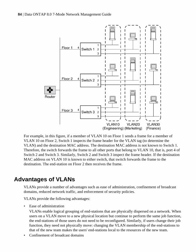
For example, in this figure, if a member of VLAN 10 on Floor 1 sends a frame for a member ofVLAN 10 on Floor 2, Switch 1 inspects the frame header for the VLAN tag (to determine theVLAN) and the destination MAC address. The destination MAC address is not known to Switch 1.Therefore, the switch forwards the frame to all other ports that belong to VLAN 10, that is, port 4 ofSwitch 2 and Switch 3. Similarly, Switch 2 and Switch 3 inspect the frame header. If the destinationMAC address on VLAN 10 is known to either switch, that switch forwards the frame to thedestination. The end-station on Floor 2 then receives the frame.
Advantages of VLANsVLANs provide a number of advantages such as ease of administration, confinement of broadcastdomains, reduced network traffic, and enforcement of security policies.
VLANs provide the following advantages:
• Ease of administrationVLANs enable logical grouping of end-stations that are physically dispersed on a network. Whenusers on a VLAN move to a new physical location but continue to perform the same job function,the end-stations of those users do not need to be reconfigured. Similarly, if users change their jobfunction, they need not physically move: changing the VLAN membership of the end-stations tothat of the new team makes the users' end-stations local to the resources of the new team.
• Confinement of broadcast domains
84 | Data ONTAP 8.0 7-Mode Network Management Guide

VLANs reduce the need to have routers deployed on a network to contain broadcast traffic.Flooding of a packet is limited to the switch ports that belong to a VLAN.
• Reduction in network trafficConfinement of broadcast domains on a network significantly reduces traffic.
• Enforcement of security policiesBy confining the broadcast domains, end-stations on a VLAN are prevented from listening to orreceiving broadcasts not intended for them. Moreover, if a router is not connected between theVLANs, the end-stations of a VLAN cannot communicate with the end-stations of the otherVLANs.
Prerequisites for setting up VLANsYou must meet certain prerequisites for switches and end-stations before you can set up VLANs in anetwork.
The following are the prerequisites for setting up VLANs:
• The switches deployed in the network either must comply with IEEE 802.1Q standards or musthave a vendor-specific implementation of VLANs.
• For an end-station to support multiple VLANs, it must be able to dynamically register (usingGVRP) or must be statically configured to belong to one or more VLANs.
Guidelines for setting up VLANs in Data ONTAPVLANs in Data ONTAP are implemented in compliance with the IEEE 802.1Q standard.
You should keep these guidelines in mind when setting up VLANs in Data ONTAP:
• You cannot set up VLANs using the setup procedure.You must use the command-line interface or FilerView to create, change, or delete VLANs.
• You must add the commands to create VLANs on the storage system to the /etc/rc file to makethe VLANs persistent across reboots.
• You can create any number of VLANs on a NIC (supporting IEEE 802.1Q) on the storagesystem.However, Data ONTAP imposes a limit on the number of interfaces (including physical, interfacegroup, VLAN, vh, and loopback interfaces) per storage system.
• You can create VLANs on physical interfaces and interface groups.• You can use VLANs to support packets of different Maximum Transmission Unit (MTU) sizes
on the same network interface.If a network interface is a member of multiple VLANs, you can specify different MTU sizes forindividual VLANs.
• You can assign an identification number from 1 to 4094 to a VLAN.
How VLANs work | 85

• You must ensure that the interface on your storage system is also a member of its partner'sVLANs in an HA pair.
• You cannot configure any parameters except mediatype for the physical network interfaceconfigured to handle VLANs.
Related concepts
Maximum number of network interfaces on page 23
The vlan command syntaxYou can use the vlan command to create, add interfaces to, delete, modify, and view the statistics ofa VLAN.
The following table gives the syntax of the vlan command:
Command Description
vlan create [-g {on|off}] ifnamevlanid_list
Create a VLAN
vlan add ifname vlanid_list Add an interface to a VLAN
vlan delete -q ifname [vlanid_list] Delete an interface from a VLAN
vlan modify -g {on|off} ifname Enable or disable GVRP on VLAN interfaces
vlan stat ifname [vlanid_list] View the statistics of the network interfaces of aVLAN
For more information about the vlan command, see the na_vlan(1) man page.
Note: The VLANs created or changed using the vlan command are not persistent across rebootsunless the vlan commands are added to the /etc/rc file.
Creating a VLANYou can create a VLAN for ease of administration, confinement of broadcast domains, reducednetwork traffic, and enforcement of security policies. You can use the vlan create command toinclude an interface in one or more VLANs as specified by the VLAN identifier, enable VLANtagging, and optionally enable GVRP.
About this task
• By default, GVRP is disabled on VLAN interfaces created by using the vlan create command;however, you can enable it with the -g option of the vlan create command.
86 | Data ONTAP 8.0 7-Mode Network Management Guide
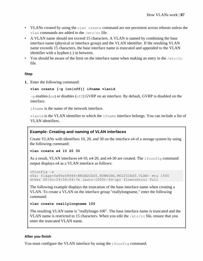
• VLANs created by using the vlan create command are not persistent across reboots unless thevlan commands are added to the /etc/rc file.
• A VLAN name should not exceed 15 characters. A VLAN is named by combining the baseinterface name (physical or interface group) and the VLAN identifier. If the resulting VLANname exceeds 15 characters, the base interface name is truncated and appended to the VLANidentifier with a hyphen (-) in between.
• You should be aware of the limit on the interface name when making an entry in the /etc/rcfile.
Step
1. Enter the following command:
vlan create [-g {on|off}] ifname vlanid
-g enables (on) or disables (off) GVRP on an interface. By default, GVRP is disabled on theinterface.
ifname is the name of the network interface.
vlanid is the VLAN identifier to which the ifname interface belongs. You can include a list ofVLAN identifiers.
Example: Creating and naming of VLAN interfaces
Create VLANs with identifiers 10, 20, and 30 on the interface e4 of a storage system by usingthe following command:
vlan create e4 10 20 30
As a result, VLAN interfaces e4-10, e4-20, and e4-30 are created. The ifconfig commandoutput displays e4 as a VLAN interface as follows:
ifconfig -ae0a: flags=0x80e08866<BROADCAST,RUNNING,MULTICAST,VLAN> mtu 1500ether 00:0c:29:56:54:7e (auto-1000t-fd-up) flowcontrol full
The following example displays the truncation of the base interface name when creating aVLAN. To create a VLAN on the interface group "reallylongname," enter the followingcommand:
vlan create reallylongname 100
The resulting VLAN name is "reallylongn-100". The base interface name is truncated and theVLAN name is restricted to 15 characters. When you edit the /etc/rc file, ensure that youenter the truncated VLAN name.
After you finish
You must configure the VLAN interface by using the ifconfig command.
How VLANs work | 87

Related concepts
Prerequisites for setting up VLANs on page 85
Guidelines for setting up VLANs in Data ONTAP on page 85
Configuring a VLANAfter you create a VLAN, you must configure it with an IP address. By using the ifconfigcommand, you can configure all the parameters for a VLAN interface in the same way that youconfigure the parameters for a physical interface.
About this task
You can configure the following parameters for a VLAN:
• IP address• Network mask• Interface status• Partner
Step
1. Enter the following command:
ifconfig ifname-vlanid IP_address netmask mask
ifname-vlanid is the VLAN interface name.
IP_address is the IP address for this interface.
mask is the network mask for this interface.
Example
Create VLANs with identifiers 1760 on the interface e5a of a storage system by using thefollowing command:
vlan create e5a 1760
Configure the VLAN interface e5a-1760 by using the following command:
ifconfig e5a-1760 192.0.2.11 netmask 255.255.255.0
Related concepts
Configuring network interfaces on page 33
88 | Data ONTAP 8.0 7-Mode Network Management Guide

How to use VLANs for tagged and untagged network trafficYou can configure an IP address for an interface with VLANs. Any untagged traffic goes to the baseinterface and the tagged traffic goes to the respective VLAN.
You can use the ifconfig command to configure an IP address for the underlying interface of theVLAN. Any tagged frame is received by the matching VLAN interface. Untagged traffic is receivedby the native VLAN on the underlying interface.
Note: You should not create a VLAN on a physical interface with the same identifier as the nativeVLAN of the switch. For example, if the network interface e0b is on native VLAN 10, you shouldnot create a VLAN e0b-10 on that interface.
You cannot bring down a network interface that is configured to receive tagged and untagged traffic(IP configured for the underlying interface and VLANs). You must bring down all VLANs on theunderlying interface before you bring down the interface. However, you can delete the IP address ofthe underlying interface.
When you configure a VLAN using GVRP, the GVRP packets are sent as both untagged and taggedfrom the native VLAN.
For information about reverting with a configuration for receiving tagged and untagged frames on thesame network interface, see the Data ONTAP 7-Mode Upgrade Guide.
Adding an interface to a VLANIf a physical interface does not belong to any VLAN, you can use the vlan create command tomake the interface a member of one or more VLANs. However, if the interface is already a memberof a VLAN, you should use the vlan add command to add the interface to subsequent VLANs.
About this task
VLANs created using the vlan add commands are not persistent across reboots unless the vlancommands are added to the /etc/rc file.
Step
1. Enter the following command:
vlan add interface_name vlanid
interface_name is the name of the network interface.
vlanid is the VLAN identifier to which the interface belongs. You can include a list of VLANidentifiers.
How VLANs work | 89
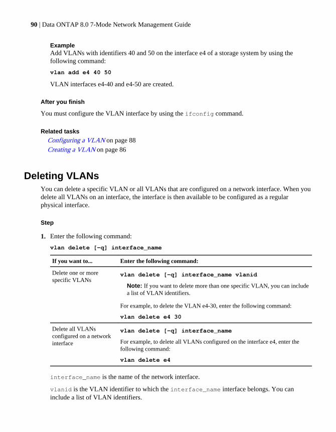
ExampleAdd VLANs with identifiers 40 and 50 on the interface e4 of a storage system by using thefollowing command:
vlan add e4 40 50
VLAN interfaces e4-40 and e4-50 are created.
After you finish
You must configure the VLAN interface by using the ifconfig command.
Related tasks
Configuring a VLAN on page 88
Creating a VLAN on page 86
Deleting VLANsYou can delete a specific VLAN or all VLANs that are configured on a network interface. When youdelete all VLANs on an interface, the interface is then available to be configured as a regularphysical interface.
Step
1. Enter the following command:
vlan delete [-q] interface_name
If you want to... Enter the following command:
Delete one or morespecific VLANs
vlan delete [-q] interface_name vlanid
Note: If you want to delete more than one specific VLAN, you can includea list of VLAN identifiers.
For example, to delete the VLAN e4-30, enter the following command:
vlan delete e4 30
Delete all VLANsconfigured on a networkinterface
vlan delete [-q] interface_name
For example, to delete all VLANs configured on the interface e4, enter thefollowing command:
vlan delete e4
interface_name is the name of the network interface.
vlanid is the VLAN identifier to which the interface_name interface belongs. You caninclude a list of VLAN identifiers.
90 | Data ONTAP 8.0 7-Mode Network Management Guide
-q option invokes the quiet mode.
Result
By default, the vlan delete command prompts you to confirm the deletion.
Note: If you do not want to receive this prompt, use the -q option with the vlan deletecommand. This action invokes the quiet mode, which causes the operation to complete withoutprompting.
Enabling or disabling GVRP on your VLAN interfaceGVRP dynamically registers the VLAN memberships of stations on your network. This reduces theoverhead of maintaining static VLAN configuration on switch ports every time a change occurs inyour network. To enable or disable GVRP on all interfaces of a network adapter, you should use thevlan modify command.
About this task
• When you enable GVRP on a network interface, it is enabled on all the associated VLANs.For example, you can enable GVRP only on the network interface e8 of a storage system.However, you cannot enable or disable GVRP for the VLAN e8-2.
• If you enable GVRP on an interface that is configured to the down status, the state of the interfaceand all associated VLAN interfaces is automatically configured to the up status.This state change occurs so that the interface can start sending VLAN registration frames toregister its VLAN membership with the switch.
• VLANs modified using the vlan modify command are not persistent across reboots unless thevlan commands are added to the /etc/rc file.
Step
1. Enter the following command:
vlan modify -g {on|off} adap_name
-g on enables GVRP.
-g off disables GVRP.
adap_name is the name of the network adapter.
Related concepts
GARP VLAN Registration Protocol on page 83
GVRP configuration for VLAN interfaces on page 83
How VLANs work | 91

Viewing VLAN statisticsYou can use the vlan stat command to view the statistics of all VLANs configured on a networkinterface. You can view the frames received and transmitted on an interface and the number offrames that were rejected because the frames did not belong to any of the VLAN groups.
Step
1. Enter the following command:
vlan stat interface_name
interface_name is the name of the network interface.
ExampleThe following example displays the statistics of all VLANs on a storage system:
vlan stat e4 Vlan Physical Interface: e4 (5 hours, 50 minutes, 38 seconds) -- Vlan IDs: 3,5GVRP: enabled
RECEIVE STATISTICSTotal frames: 0 | Total bytes: 0 |Multi/broadcast: 0
Untag drops:0 | Vlan tag drops: 0
TRANSMIT STATISTICS Total frames: 8 | Total bytes: 368
Vlan Interface: e4-3 (0 hours, 20 minutes, 45 seconds) --
ID: 3 MAC Address: 00:90:27:5c:58:14
Viewing statistics for a specific VLANYou can use the vlan stat command to view the statistics for a specific VLAN configured on anetwork interface. You can view the frames received and transmitted on an interface and the numberof frames that were rejected because the frames did not belong to any of the VLAN groups.
Step
1. Enter the following command:
vlan stat interface_name vlanid
interface_name is the name of the network interface.
92 | Data ONTAP 8.0 7-Mode Network Management Guide

vlanid is the VLAN identifier to which the interface_name interface belongs. You caninclude a list of VLAN identifiers.
How VLANs work | 93


How interface groups work in Data ONTAP
An interface group is a feature in Data ONTAP that implements link aggregation on your storagesystem. Interface groups provide a mechanism to group together multiple network interfaces (links)into one logical interface (aggregate). After an interface group is created, it is indistinguishable froma physical network interface.
The following figure shows four separate network interfaces, e3a, e3b, e3c, and e3d, before they aregrouped into an interface group.
The following figure shows the four network interfaces grouped into a single interface group calledTrunk1.
Different vendors refer to interface groups by the following terms:
• Virtual aggregations• Link aggregations• Trunks• EtherChannel
Interface groups provide several advantages over individual network interfaces:
How interface groups work in Data ONTAP | 95

• Higher throughputMultiple interfaces work as one interface.
• Fault toleranceIf one interface in an interface group goes down, your storage system stays connected to thenetwork by using the other interfaces.
• No single point of failureIf the physical interfaces in an interface group are connected to multiple switches and a switchgoes down, your storage system stays connected to the network through the other switches.
Next topics
Types of interface groups on page 96
Load balancing in multimode interface groups on page 100
Guidelines for configuring interface groups on page 101
The ifgrp command on page 101
Creating a single-mode interface group on page 102
Creating a static multimode interface group on page 105
Creating a dynamic multimode interface group on page 107
Adding interfaces to an interface group on page 108
Deleting interfaces from an interface group on page 109
Viewing interface group status on page 110
Viewing interface group statistics on page 112
Destroying an interface group on page 113
Second-level interface groups on page 113
Second-level interface groups in an HA pair on page 116
Types of interface groupsYou can create three different types of interface groups on your storage system: single-modeinterface groups, static multimode interface groups, and dynamic multimode interface groups.
Each interface group provides different levels of fault tolerance. Multimode interface groups providemethods for load balancing network traffic.
Next topics
Single-mode interface group on page 97
Static multimode interface group on page 97
Dynamic multimode interface group on page 98
96 | Data ONTAP 8.0 7-Mode Network Management Guide

Single-mode interface groupIn a single-mode interface group, only one of the interfaces in the interface group is active. The otherinterfaces are on standby, ready to take over if the active interface fails. All interfaces in a single-mode interface group share a common MAC address.
There can be more than one interface on standby in a single-mode interface group. If an activeinterface fails, your storage system randomly picks one of the standby interfaces to be the next activelink. The active link is monitored and link failover is controlled by the storage system; therefore,single-mode interface group does not require any switch configuration. Single-mode interface groupsalso do not require a switch that supports link aggregation.
The following figure is an example of a single-mode interface group. In the figure, e0 and e1 are partof the SingleTrunk1 single-mode interface group. If the active interface, e0, fails, the standby e1interface takes over and maintains the connection to the switch.
Static multimode interface groupThe static multimode interface group implementation in Data ONTAP is in compliance with IEEE802.3ad (static). Any switch that supports aggregates, but does not have control packet exchange forconfiguring an aggregate, can be used with static multimode interface groups.
Static multimode interface groups do not support IEEE 802.3ad (dynamic), also known as LinkAggregation Control Protocol (LACP). Port Aggregation Protocol (PAgP), the proprietary linkaggregation protocol from Cisco, too is not supported.
In a static multimode interface group, all interfaces in the interface group are active and share asingle MAC address. This logical aggregation of interfaces provides higher throughput than a single-mode interface group. Static multimode interface groups can recover from a failure of up to "n-1"interfaces, where n is the total number of interfaces that form the interface group.
A static multimode interface group requires a switch that supports link aggregation over multipleswitch ports. The switch is configured so that all ports to which links of an interface group areconnected are part of a single logical port. Some switches might not support link aggregation of portsconfigured for jumbo frames. For more information, see your switch vendor's documentation.
How interface groups work in Data ONTAP | 97

Several load-balancing options are available to distribute traffic among the interfaces of a staticmultimode interface group.
The IEEE 802.3 standard states that the transmitting device in an aggregated link determines thephysical interface for transmission. Therefore, Data ONTAP is only responsible for distributingoutbound traffic and cannot control how inbound frames arrive. If an administrator wants to manageor control the transmission of inbound traffic on an aggregated link, it must be modified on thedirectly connected network device.
The following figure is an example of a static multimode interface group. Interfaces e0, e1, e2, ande3 are part of the MultiTrunk1 multimode interface group. All four interfaces in the MultiTrunk1multimode interface group are active.
Several technologies exist that enable traffic in a single aggregated link to be distributed acrossmultiple physical switches. The technologies used to enable this capability vary among networkingproducts. Static multimode interface groups in Data ONTAP conform to the IEEE 802.3 standards. Ifa particular multiple switch link aggregation technology is stated to interoperate or conform to theIEEE 802.3 standards, it should operate with Data ONTAP.
Dynamic multimode interface groupDynamic multimode interface groups can detect not only the loss of link status (as do staticmultimode interface groups), but also a loss of data flow. This feature makes dynamic multimodeinterface groups compatible with high-availability environments. The dynamic multimode interfacegroup implementation in Data ONTAP is in compliance with IEEE 802.3ad (dynamic), also knownas Link Aggregation Control Protocol (LACP).
Dynamic multimode interface groups have some special requirements. They include the following:
• Dynamic multimode interface groups must be connected to a switch that supports LACP.• Dynamic multimode interface groups must be configured as first-level interface groups.• Dynamic multimode interface groups should be configured to use the port-based and IP-based
load-balancing methods.
98 | Data ONTAP 8.0 7-Mode Network Management Guide

In a dynamic multimode interface group, all interfaces in the interface group are active and share asingle MAC address. This logical aggregation of interfaces provides higher throughput than a single-mode interface group.
A dynamic multimode interface group requires a switch that supports link aggregation over multipleswitch ports. The switch is configured so that all ports to which links of an interface group areconnected are part of a single logical port. For information about configuring the switch, see yourswitch vendor's documentation. Some switches might not support link aggregation of portsconfigured for jumbo frames. For more information, see your switch vendor's documentation.
Attention: Data ONTAP supports only the active and passive modes of LACP.
Several load-balancing options are available to distribute traffic among the interfaces of a dynamicmultimode interface group.
The IEEE 802.3 standard states that the transmitting device in an aggregated link determines thephysical interface for transmission. Therefore, Data ONTAP is only responsible for distributingoutbound traffic and cannot control how inbound frames arrive. If an administrator wants to manageor control the transmission of inbound traffic on an aggregated link, it must be modified on thedirectly connected network device.
The following figure is an example of a dynamic multimode interface group. Interfaces e0, e1, e2,and e3 are part of the MultiTrunk1 multimode interface group. All four interfaces in the MultiTrunk1dynamic multimode interface group are active.
Several technologies exist that enable traffic in a single aggregated link to be distributed acrossmultiple physical switches. The technologies used to enable this capability vary among networkingproducts. Dynamic multimode interface groups in Data ONTAP conform to the IEEE 802.3standards. If a particular multiple switch link aggregation technology is stated to interoperate orconform to the IEEE 802.3 standards, it should operate with Data ONTAP.
How interface groups work in Data ONTAP | 99
Load balancing in multimode interface groupsYou can ensure that all interfaces of a multimode interface group are equally utilized for outgoingtraffic by using the IP address, MAC address, round-robin, or port based load-balancing methods todistribute network traffic equally over the network ports of a multimode interface group.
The load-balancing method for a multimode interface group can be specified only when the interfacegroup is created. If no method is specified, the IP address based load-balancing method is used.
Next topics
IP address and MAC address load balancing on page 100
Round-robin load balancing on page 100
Port-based load balancing on page 100
IP address and MAC address load balancingIP address and MAC address load balancing are the methods for equalizing traffic on multimodeinterface groups.
These load-balancing methods use a fast hashing algorithm on the source and destination addresses(IP address and MAC address). If the result of the hashing algorithm maps to an interface that is notin the UP link-state, the next active interface is used.
Note: Do not select the MAC address load-balancing method when creating interface groups on astorage system that connects directly to a router. In such a setup, for every outgoing IP frame, thedestination MAC address is the MAC address of the router. As a result, only one interface of theinterface group is used.
Round-robin load balancingYou can use round-robin for load balancing multimode interface groups. You should use the round-robin option for load balancing a single connection's traffic across multiple links to increase singleconnection throughput. However, this method might cause out-of-order packet delivery.
If the remote TCP endpoints do not handle TCP reassembly correctly or lack enough memory tostore out-of-order packets, they might be forced to drop packets. Therefore, this can lead tounnecessary retransmissions from the storage controller.
Port-based load balancingYou can equalize traffic on a multimode interface group based on the transport layer (TCP/UDP)ports by using the port-based load-balancing method.
The port-based load-balancing method uses a fast hashing algorithm on the source and destination IPaddresses along with the transport layer port number.
100 | Data ONTAP 8.0 7-Mode Network Management Guide
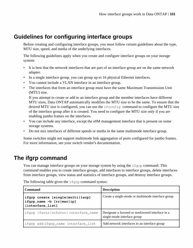
Guidelines for configuring interface groupsBefore creating and configuring interface groups, you must follow certain guidelines about the type,MTU size, speed, and media of the underlying interfaces.
The following guidelines apply when you create and configure interface groups on your storagesystem:
• It is best that the network interfaces that are part of an interface group are on the same networkadapter.
• In a single interface group, you can group up to 16 physical Ethernet interfaces.• You cannot include a VLAN interface in an interface group.• The interfaces that form an interface group must have the same Maximum Transmission Unit
(MTU) size.If you attempt to create or add to an interface group and the member interfaces have differentMTU sizes, Data ONTAP automatically modifies the MTU size to be the same. To ensure that thedesired MTU size is configured, you can use the ifconfig command to configure the MTU sizeof the interface group after it is created. You need to configure the MTU size only if you areenabling jumbo frames on the interfaces.
• You can include any interface, except the e0M management interface that is present on somestorage systems.
• Do not mix interfaces of different speeds or media in the same multimode interface group.
Some switches might not support multimode link aggregation of ports configured for jumbo frames.For more information, see your switch vendor's documentation.
The ifgrp commandYou can manage interface groups on your storage system by using the ifgrp command. Thiscommand enables you to create interface groups, add interfaces to interface groups, delete interfacesfrom interface groups, view status and statistics of interface groups, and destroy interface groups.
The following table gives the ifgrp command syntax:
Command Description
ifgrp create [single|multi|lacp]ifgrp_name -b [rr|mac|ip][interface_list]
Create a single-mode or multimode interface group
ifgrp {favor|nofavor} interface_name Designate a favored or nonfavored interface in asingle-mode interface group
ifgrp add ifgrp_name interface_list Add network interfaces to an interface group
How interface groups work in Data ONTAP | 101
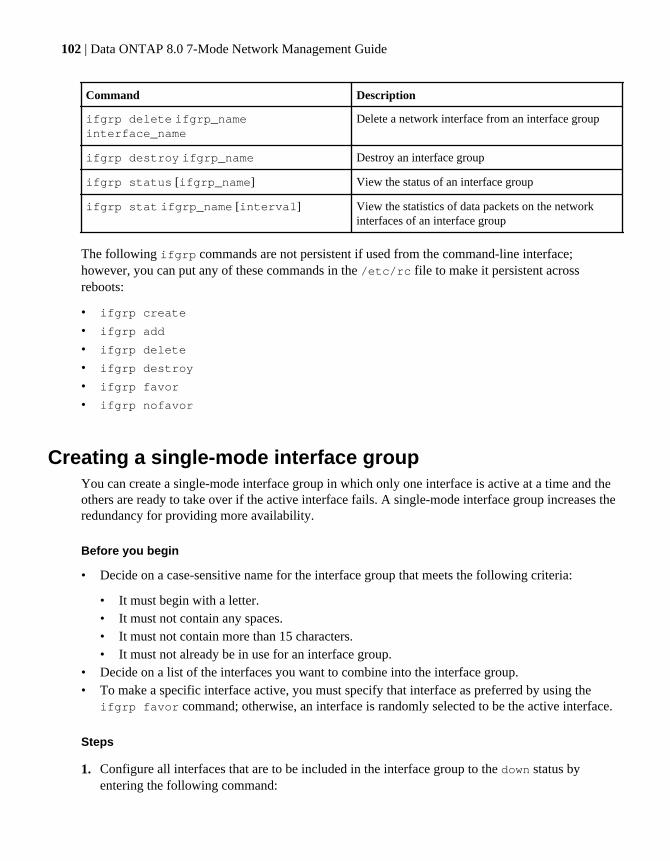
Command Description
ifgrp delete ifgrp_nameinterface_name
Delete a network interface from an interface group
ifgrp destroy ifgrp_name Destroy an interface group
ifgrp status [ifgrp_name] View the status of an interface group
ifgrp stat ifgrp_name [interval] View the statistics of data packets on the networkinterfaces of an interface group
The following ifgrp commands are not persistent if used from the command-line interface;however, you can put any of these commands in the /etc/rc file to make it persistent acrossreboots:
• ifgrp create
• ifgrp add
• ifgrp delete
• ifgrp destroy
• ifgrp favor
• ifgrp nofavor
Creating a single-mode interface groupYou can create a single-mode interface group in which only one interface is active at a time and theothers are ready to take over if the active interface fails. A single-mode interface group increases theredundancy for providing more availability.
Before you begin
• Decide on a case-sensitive name for the interface group that meets the following criteria:
• It must begin with a letter.• It must not contain any spaces.• It must not contain more than 15 characters.• It must not already be in use for an interface group.
• Decide on a list of the interfaces you want to combine into the interface group.• To make a specific interface active, you must specify that interface as preferred by using the
ifgrp favor command; otherwise, an interface is randomly selected to be the active interface.
Steps
1. Configure all interfaces that are to be included in the interface group to the down status byentering the following command:
102 | Data ONTAP 8.0 7-Mode Network Management Guide
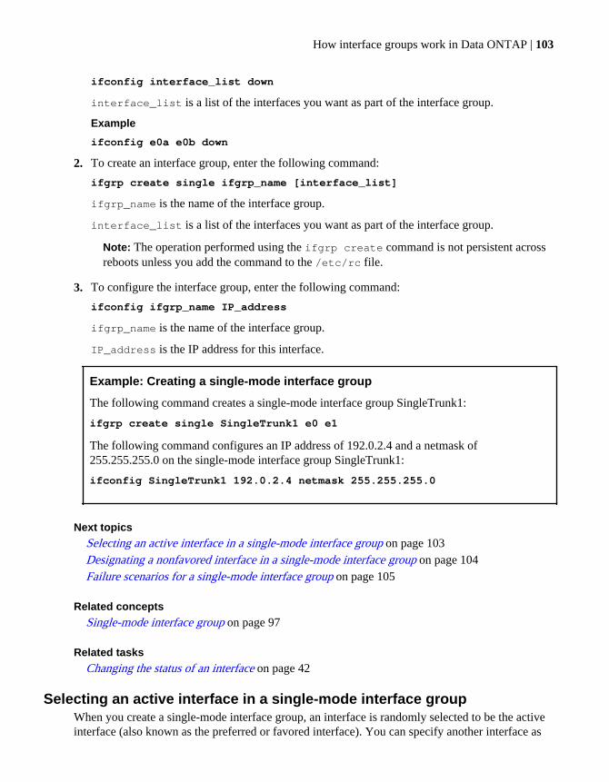
ifconfig interface_list down
interface_list is a list of the interfaces you want as part of the interface group.
Example
ifconfig e0a e0b down
2. To create an interface group, enter the following command:
ifgrp create single ifgrp_name [interface_list]
ifgrp_name is the name of the interface group.
interface_list is a list of the interfaces you want as part of the interface group.
Note: The operation performed using the ifgrp create command is not persistent acrossreboots unless you add the command to the /etc/rc file.
3. To configure the interface group, enter the following command:
ifconfig ifgrp_name IP_address
ifgrp_name is the name of the interface group.
IP_address is the IP address for this interface.
Example: Creating a single-mode interface group
The following command creates a single-mode interface group SingleTrunk1:
ifgrp create single SingleTrunk1 e0 e1
The following command configures an IP address of 192.0.2.4 and a netmask of255.255.255.0 on the single-mode interface group SingleTrunk1:
ifconfig SingleTrunk1 192.0.2.4 netmask 255.255.255.0
Next topicsSelecting an active interface in a single-mode interface group on page 103Designating a nonfavored interface in a single-mode interface group on page 104Failure scenarios for a single-mode interface group on page 105
Related conceptsSingle-mode interface group on page 97
Related tasksChanging the status of an interface on page 42
Selecting an active interface in a single-mode interface groupWhen you create a single-mode interface group, an interface is randomly selected to be the activeinterface (also known as the preferred or favored interface). You can specify another interface as
How interface groups work in Data ONTAP | 103
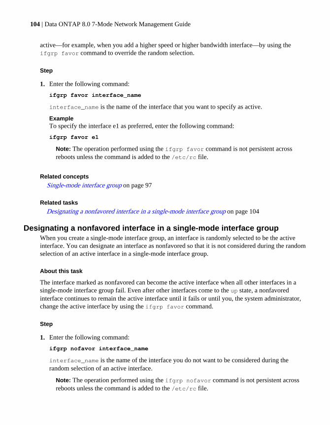
active—for example, when you add a higher speed or higher bandwidth interface—by using theifgrp favor command to override the random selection.
Step
1. Enter the following command:
ifgrp favor interface_name
interface_name is the name of the interface that you want to specify as active.
ExampleTo specify the interface e1 as preferred, enter the following command:
ifgrp favor e1
Note: The operation performed using the ifgrp favor command is not persistent acrossreboots unless the command is added to the /etc/rc file.
Related concepts
Single-mode interface group on page 97
Related tasks
Designating a nonfavored interface in a single-mode interface group on page 104
Designating a nonfavored interface in a single-mode interface groupWhen you create a single-mode interface group, an interface is randomly selected to be the activeinterface. You can designate an interface as nonfavored so that it is not considered during the randomselection of an active interface in a single-mode interface group.
About this task
The interface marked as nonfavored can become the active interface when all other interfaces in asingle-mode interface group fail. Even after other interfaces come to the up state, a nonfavoredinterface continues to remain the active interface until it fails or until you, the system administrator,change the active interface by using the ifgrp favor command.
Step
1. Enter the following command:
ifgrp nofavor interface_name
interface_name is the name of the interface you do not want to be considered during therandom selection of an active interface.
Note: The operation performed using the ifgrp nofavor command is not persistent acrossreboots unless the command is added to the /etc/rc file.
104 | Data ONTAP 8.0 7-Mode Network Management Guide
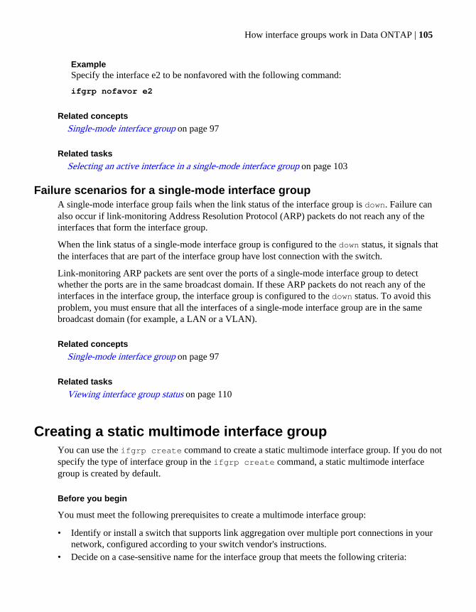
ExampleSpecify the interface e2 to be nonfavored with the following command:
ifgrp nofavor e2
Related concepts
Single-mode interface group on page 97
Related tasks
Selecting an active interface in a single-mode interface group on page 103
Failure scenarios for a single-mode interface groupA single-mode interface group fails when the link status of the interface group is down. Failure canalso occur if link-monitoring Address Resolution Protocol (ARP) packets do not reach any of theinterfaces that form the interface group.
When the link status of a single-mode interface group is configured to the down status, it signals thatthe interfaces that are part of the interface group have lost connection with the switch.
Link-monitoring ARP packets are sent over the ports of a single-mode interface group to detectwhether the ports are in the same broadcast domain. If these ARP packets do not reach any of theinterfaces in the interface group, the interface group is configured to the down status. To avoid thisproblem, you must ensure that all the interfaces of a single-mode interface group are in the samebroadcast domain (for example, a LAN or a VLAN).
Related concepts
Single-mode interface group on page 97
Related tasks
Viewing interface group status on page 110
Creating a static multimode interface groupYou can use the ifgrp create command to create a static multimode interface group. If you do notspecify the type of interface group in the ifgrp create command, a static multimode interfacegroup is created by default.
Before you begin
You must meet the following prerequisites to create a multimode interface group:
• Identify or install a switch that supports link aggregation over multiple port connections in yournetwork, configured according to your switch vendor's instructions.
• Decide on a case-sensitive name for the interface group that meets the following criteria:
How interface groups work in Data ONTAP | 105

• It must begin with a letter.• It must not contain a space.• It must not contain more than 15 characters.• It must not already be in use for an interface group.
• Decide on the interfaces that you want to select as part of the interface group.• Configure all interfaces that are to be included in the interface group to the down status, by using
the ifconfig command.
About this task
You can improve throughput by creating a static multimode interface group. With a multimodeinterface group, all interfaces in the interface group are active and share a single MAC address. Thislogical aggregation of interfaces provides higher throughput than a single-mode interface group.
Steps
1. To create the interface group, enter the following command:
ifgrp create multi ifgrp_name -b {rr|mac|ip|port} [interface_list]
-b describes the load-balancing method.
rr specifies round-robin load balancing.
mac specifies MAC address load balancing.
Note: Do not select the MAC address load-balancing method when creating interface groupson a storage system that connects directly to a router. In such a setup, for every outgoing IPframe, the destination MAC address is the MAC address of the router. As a result, only oneinterface of the interface group is used.
ip indicates IP address load balancing (default).
port indicates port-based load balancing.
ifgrp_name is the name of a previously created interface group.
interface_list is a list of the interfaces you want to add to the interface group.
ExampleTo create a static multimode interface group, comprising interfaces e0, e1, e2, and e3 and usingMAC address load balancing, enter the following command:
ifgrp create multi MultiTrunk1 -b mac e0 e1 e2 e3
2. To configure the interface group, enter the following command:
ifconfig ifgrp_name IP_address netmask mask
Related concepts
Static multimode interface group on page 97
106 | Data ONTAP 8.0 7-Mode Network Management Guide
Load balancing in multimode interface groups on page 100
Related tasks
Changing the status of an interface on page 42
Creating a dynamic multimode interface groupWith a dynamic multimode interface group, all interfaces in the interface group are active and share asingle MAC address. This logical aggregation of interfaces provides higher throughput than a single-mode interface group. Dynamic multimode interface groups can detect both loss of link and loss ofdata flow.
Before you begin
You must meet the following prerequisites to create a multimode interface group:
• Identify or install a switch that supports LACP over multiple port connections in your network,configured according to your switch vendor's instructions.
• Decide on a case-sensitive name for the interface group that meets the following criteria:
• It must begin with a letter.• It must not contain a space.• It must not contain more than 15 characters.• It must not already be in use for an interface group.
• Decide on the interfaces you want to select as part of the interface group.• Configure all interfaces that are to be included in the interface group to the down status, by using
the ifconfig command.
About this task
Data ONTAP logs information about the LACP negotiation for dynamic multimode interface groupsin the /vol0/etc/log/lacp_log file.
Steps
1. To create a dynamic multimode interface group, enter the following command:
ifgrp create lacp ifgrp_name -b {rr|mac|ip|port} [interface_list]
-b specifies the load-balancing method.
rr specifies round-robin load balancing.
mac specifies MAC address load balancing.
Note: Do not select the MAC address load-balancing method when creating interface groupson a storage system that connects directly to a router. In such a setup, for every outgoing IP
How interface groups work in Data ONTAP | 107
frame, the destination MAC address is the MAC address of the router. As a result, only oneinterface of the interface group is used.
ip specifies IP address based load balancing (default).
port indicates port-based load balancing.
ifgrp_name is the name of a previously created interface group.
interface_list is a list of the interfaces that form the interface group.
ExampleTo create a dynamic multimode interface group, comprising interfaces e0, e1, e2, and e3 andusing IP address based load balancing, enter the following command:
ifgrp create lacp MultiTrunk1 -b ip e0 e1 e2 e3
2. To configure the dynamic multimode interface group, enter the following command:
ifconfig ifgrp_name IP_address netmask mask
Related concepts
Dynamic multimode interface group on page 98
Load balancing in multimode interface groups on page 100
Related tasks
Changing the status of an interface on page 42
Adding interfaces to an interface groupYou can add one or more interfaces to an interface group to expand your network. You can addphysical interfaces to an interface group any time after you create it by using the ifgrp addcommand.
Before you begin
• You must configure additional ports on the switch where the new interfaces will be connected.For information about configuring the switch, see your switch vendor's documentation.
• The interface to be added to the interface group must be configured to the down status by usingthe ifconfig command.
Step
1. Enter the following command:
ifgrp add ifgrp_name interface_list
ifgrp_name is the name of a previously configured interface group.
108 | Data ONTAP 8.0 7-Mode Network Management Guide
interface_list is a list of the interfaces you want to add to the interface group.
Note: The operation performed using the ifgrp add command is not persistent across rebootsunless the command is added to the /etc/rc file.
ExampleTo add the interface e4 to the multimode interface group MultiTrunk1, enter with the followingcommand:
ifgrp add MultiTrunk1 e4
Related tasks
Changing the status of an interface on page 42
Deleting interfaces from an interface groupYou might have to delete a physical interface from an interface group—for example, when theinterface needs maintenance or when you want to use the interface for a different purpose. You canuse the ifgrp delete command to delete one or more interfaces from an interface group.
Before you begin
You must configure the interface group to the down state before you can delete a network interfacefrom the interface group. You can configure the interface group to the down status by using thefollowing command:
ifconfig ifgrp_name down
ifgrp_name is the name of the interface group that you want to configure to the down status.
About this task
The operation performed using the ifgrp delete command is not persistent across reboots unlessthe command is added to the /etc/rc file.
Step
1. Enter the following command:
ifgrp delete ifgrp_name interface
ifgrp_name is the name of the interface group.
interface is the interface of the interface group you want to delete.
ExampleTo delete the interface e4 from a multimode interface group MultiTrunk1, enter the followingcommands:
ifconfig MultiTrunk1 down
How interface groups work in Data ONTAP | 109

ifgrp delete MultiTrunk1 e4
Related tasks
Changing the status of an interface on page 42
Viewing interface group statusYou can view the current status of a specified interface group or all single-mode and multimodeinterface groups on your storage system.
Step
1. Enter the following command:
ifgrp status [ifgrp_name]
ifgrp_name is the name of the interface group whose status you want to display.
If you do not specify the interface group name, the status of all interface groups is displayed.
Example
The following example displays the status of the interface group ifgrp1:
ifgrp status ifgrp1default: transmit 'IP Load balancing', Ifgrp Type 'multi_mode', fail 'log'ifgrp1: 1 link, transmit 'none', Ifgrp Type 'single_mode' fail 'default' Ifgrp Status Up Addr_set up: e0b: state up, since 23Jun2009 08:18:12 (00:01:16) mediatype: auto-1000t-fd-up flags: enabled input packets 54, input bytes 4858 output packets 35, output bytes 2830 output probe packets 0, input probe packets 0 strike count: 0 of 10 up indications 1, broken indications 0 drops (if) 0, drops (link) 0 indication: up at 23Jun2009 08:18:12 consecutive 75, transitions 1 broken: e0c: state broken, since 23Jun2009 08:18:22 (00:01:06) mediatype: auto-unknown-down flags: input packets 0, input bytes 0 output packets 0, output bytes 0 output probe packets 0, input probe packets 0 strike count: 0 of 10 up indications 0, broken indications 0 drops (if) 0, drops (link) 0
110 | Data ONTAP 8.0 7-Mode Network Management Guide

indication: broken at 23Jun2009 08:18:22 consecutive 0, transitions 1
What the interface group status information table containsYou can view the status information of an interface group by using the ifgrp status command.
The following table describes the information that is shown in each field and subfield of the ifgrpstatus command output.
Field Subfield Description
default Indicates the default values for fields such as transmit, IfgrpType, and fail. These values apply if you do not specify anyvalues for these fields when creating an interface group.
transmit Indicates the default load-balancing method.
Ifgrp Type Indicates the default interface group type.
fail Indicates the default location where the errors are logged.
ifgrp_name Indicates that the data that follows this field pertains to theinterface group, ifgrp_name.
transmit Indicates the load-balancing method used.
Ifgrp Type Indicates the type of interface group. Possible values aresingle-mode, multi_mode, or lacp.
fail Indicates the location where errors are logged for the interfacegroup.
Ifgrp Status Indicates the current status of the interface group,ifgrp_name.
Addr_set Indicates that a MAC address has been configured for theinterface group, ifgrp_name, and all its interfaces.
state Indicates the current link-state of the interface. Possible valuesare up or down.
since Indicates the date, time, and number of hours since theinterface has been up.
mediatype Indicates the media type that defines the speed and duplex forthat interface.
flags Indicates whether the interface is enabled or disabled to sendand receive data.
How interface groups work in Data ONTAP | 111

Field Subfield Description
strike count Indicates the number of attempts for link-monitoring. When anunderlying link of an interface group does not receive anypackets (including ARP packets that are used for link-monitoring), the strike count gets incremented once in 5seconds. If this strike count reaches 10, the underlying link isbrought "down."
consecutive Indicates the number of consecutively received "up" or"broken" indications from the switch and link interaction.
transitions Indicates the number of indications received that caused a statetransition from "up" to "broken" or "down" to "up".
Viewing interface group statisticsYou can view the statistics for a specific interface group or for all interface groups. The statisticsinclude the number of packets received and sent by each interface group.
Step
1. Enter the following command:
ifgrp stat [ifgrp_name] [interval]
ifgrp_name is the name of the interface group. If you do not specify an interface group, thestatus of all interface groups is displayed.
interval is the interval, in seconds. The default is one second.
Example
The following example displays the output of the ifgrp stat command for a multimodeinterface group created with the round-robin load-balancing method:
ifgrp stat ifgrp0ifgrp (trunk) ifgrp0 e3a e3b Pkts In Pkts Out Pkts In Pkts Out 8637076 47801540 158 159 1617 9588 0 0 1009 5928 0 0 1269 7506 0 0 1293 7632 0 0 920 5388 0 0 1098 6462 0 0
112 | Data ONTAP 8.0 7-Mode Network Management Guide

2212 13176 0 0 1315 7776 0 0
The first row of the output shows the total number of packets received and sent until the timethe ifgrp stat command was run. The following rows show the total number of packetsreceived and sent per second thereafter.
For interface groups created with the round-robin load-balancing option, the outgoing packetsare balanced among the network interfaces of the interface group.
ifgrp stat ifgrp1Interface group (trunk) ifgrp1 e0c e0b Pkts In Pkts Out Pkts In Pkts Out 82 208k 796k 208k 1 27342 104774 27326 2 26522 102088 26560 8 20332 77275 20335 5 27198 103529 27186
Destroying an interface groupYou destroy an interface group when you no longer need it or when you want to use the interfacesthat form the interface group for other purposes. After you destroy the interface group, the interfacesin the interface group act individually rather than as an aggregate.
Steps
1. Configure the interface group to the down status by entering the following command:
ifconfig ifgrp_name down
ifgrp_name is the name of the interface group you want to configure to the down status.
2. Enter the following command:
ifgrp destroy ifgrp_name
ifgrp_name is the name of the interface group you want to destroy.
Second-level interface groupsIf you have more than one multimode interface group, you can use the ifgrp create command togroup them by creating a second layer of interface group called the second-level interface group.Second-level interface groups enable you to provide a standby multimode interface group in case theprimary multimode interface group fails.
You can use second-level interface groups on a single storage system or in an HA pair.
How interface groups work in Data ONTAP | 113
Note: You cannot use LACP interface groups as second-level interface groups.
Next topics
Guidelines for creating a second-level interface group on page 114
Creating a second-level interface group on page 114
Enabling failover in a second-level interface group on page 115
Guidelines for creating a second-level interface groupYou can create a single-mode second-level interface group over two multimode interface groups. Theports of the underlying multimode interface groups should be connected to the same switch. If youcreate a second-level interface group over two multimode interface groups that are connected to twodifferent switches, you should connect the two switches with an inter-switch link (ISL).
For a single-mode interface group, the switch ports must be in the same broadcast domain (forexample, a LAN or a VLAN). Link-monitoring ARP packets are sent over the ports of a single-modeinterface group to detect whether the ports are in the same broadcast domain. If the ports are not inthe same broadcast domain, the interface group is configured to the down status.
When the ports of a single-mode interface group are connected to different broadcast domains, it iscalled a split-network condition. Therefore, a second-level interface group, created over twomultimode interface groups that are connected to two different switches without an ISL, isautomatically configured to the down status.
Creating a second-level interface groupYou can create a second-level interface group by using two multimode interface groups. Second-level interface groups enable you to provide a standby multimode interface group in case the primarymultimode interface group fails.
Before you begin
You must meet the following prerequisites to create a second-level interface group:
• Identify or install a switch that supports link aggregation over multiple port connections in yournetwork, configured according to your switch vendor's instructions.
• Decide on a name for the second-level interface group:
• It must begin with a letter.• It must not contain a space.• It must not contain more than 15 characters.• It must not already be in use for an interface group.
• Decide on a list of the interfaces you want to select as part of the interface group.• Configure all interfaces that are to be included in the interface group to the down status, by using
the ifconfig command.
114 | Data ONTAP 8.0 7-Mode Network Management Guide

Steps
1. Enter the following command to create the first of two multimode interfaces:
ifgrp create multi -b {rr|mac|ip|port} ifgrp_name1 if1 if2
The ifgrp_name1 interface group is composed of two physical interfaces, if1 and if2.
-b—specifies the type of load-balancing method.
rr—specifies the round-robin load-balancing option.
mac—specifies the MAC address load-balancing option.
ip—indicates the IP address load-balancing option (default option).
port—indicates the port-based load-balancing option.
2. Enter the following command to create the second of two multimode interfaces:
ifgrp create multi -b {rr|mac|ip|port} ifgrp_name2 if3 if4
The ifgrp_name2 interface group is composed of two physical interfaces, if3 and if4.
3. Enter the following command to create a single-mode interface from the multimode interfaces:
ifgrp create single ifgrp_name ifgrp_name1 ifgrp_name2
ifgrp_name is the second-level interface group created with two multimode interface groups,ifgrp_name1 and ifgrp_name2.
Example
Use the following commands to create two interface groups and a second-level interfacegroup. In this example, IP address load balancing is used for the multimode interface groups.
ifgrp create multi Firstlev1 e0 e1
ifgrp create multi Firstlev2 e2 e3
ifgrp create single Secondlev Firstlev1 Firstlev2
Related tasks
Changing the status of an interface on page 42
Enabling failover in a second-level interface groupIn a second-level single-mode interface group over two or more multimode interface groups, you canenable the ifgrp.failover.link_degraded option for failing over to a multimode interface
How interface groups work in Data ONTAP | 115

group with higher aggregate bandwidth. The failover happens regardless of whether the currentlyactive interface group is favored or not. By default, this option is off.
Step
1. To enable failover to a multimode interface group with higher aggregate bandwidth when one ormore of the links in the active multimode interface group fail, enter the following command:
options ifgrp.failover.link_degraded on
Second-level interface groups in an HA pairIn an HA pair, you can access data from both storage systems even if one of the storage system in theconfiguration fails.
With a second-level interface group connected in a single-mode configuration, you can maintainconnectivity to your storage system even if one of the switches fails. Therefore, by using the twoconfigurations together, you can achieve a fully redundant storage system connectivity architecture.
The following figure shows second-level interface groups in an HA pair.
When both storage systems are in operation, the following connections exist:
• Firstlev1 in Secondlev 1 connects StorageSystem 1 to the network through Switch 1.• Firstlev2 in Secondlev 1 connects StorageSystem 1 to Switch 2.• Firstlev4 in Secondlev 2 connects StorageSystem 2 to the network through Switch 2.• Firstlev3 in Secondlev 2 connects StorageSystem 2 to Switch 1.
Firstlev2 and Firstlev3 are in standby mode.
If one of the switches fails, the following happens:
• If Switch 1 fails, Firstlev2 and Firstlev4 maintain the connection for their storage systems throughSwitch 2.
116 | Data ONTAP 8.0 7-Mode Network Management Guide

• If Switch 2 fails, Firstlev1 and Firstlev3 maintain the connection for their storage systems throughSwitch 1.
In the following figure, Switch 1 fails in an HA pair. Firstlev2 takes over the MAC address ofFirstlev1 and maintains the connectivity through Switch 2.
Creating a second-level interface group in an HA pairYou can create two second-level interface groups in an HA pair so that you can access data fromboth storage systems even if one of the storage system in the configuration fails.
Before you begin
You must ensure that all interfaces to be included in the interface group are configured to the downstatus. You can use the ifconfig command to configure an interface to the down status.
About this task
The operation performed using the ifgrp create command is not persistent across reboots unlessthe command is added to the /etc/rc file.
Assume StorageSystem1 and StorageSystem2 are the storage systems that are configured in anHA pair.
Steps
1. Enter the following commands on StorageSystem1 to create two multimode interface groups:
ifgrp create multi -b {rr|mac|ip|port} ifgrp_name1 if1 if2
ifgrp create multi -b {rr|mac|ip|port} ifgrp_name2 if3 if4
-b specifies the type of load-balancing method.
rr specifies the round-robin load-balancing option.
mac specifies the MAC address load-balancing option.
How interface groups work in Data ONTAP | 117
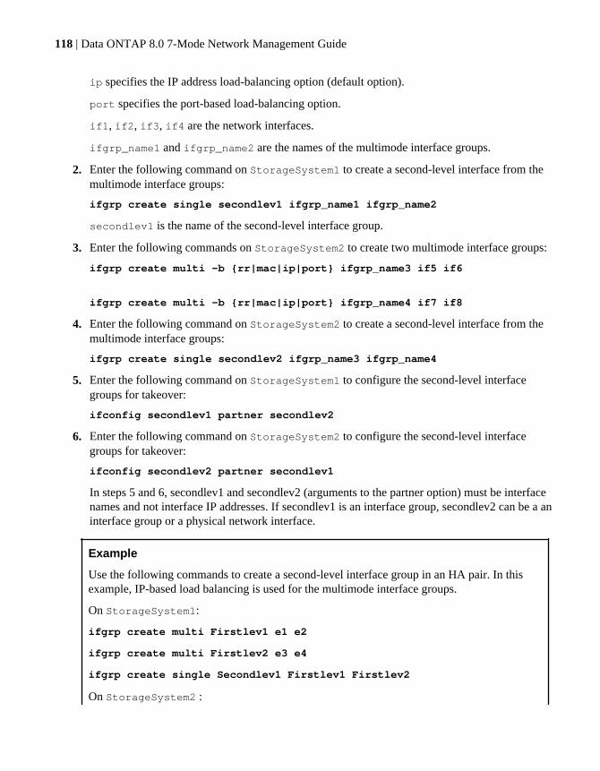
ip specifies the IP address load-balancing option (default option).
port specifies the port-based load-balancing option.
if1, if2, if3, if4 are the network interfaces.
ifgrp_name1 and ifgrp_name2 are the names of the multimode interface groups.
2. Enter the following command on StorageSystem1 to create a second-level interface from themultimode interface groups:
ifgrp create single secondlev1 ifgrp_name1 ifgrp_name2
secondlev1 is the name of the second-level interface group.
3. Enter the following commands on StorageSystem2 to create two multimode interface groups:
ifgrp create multi -b {rr|mac|ip|port} ifgrp_name3 if5 if6
ifgrp create multi -b {rr|mac|ip|port} ifgrp_name4 if7 if8
4. Enter the following command on StorageSystem2 to create a second-level interface from themultimode interface groups:
ifgrp create single secondlev2 ifgrp_name3 ifgrp_name4
5. Enter the following command on StorageSystem1 to configure the second-level interfacegroups for takeover:
ifconfig secondlev1 partner secondlev2
6. Enter the following command on StorageSystem2 to configure the second-level interfacegroups for takeover:
ifconfig secondlev2 partner secondlev1
In steps 5 and 6, secondlev1 and secondlev2 (arguments to the partner option) must be interfacenames and not interface IP addresses. If secondlev1 is an interface group, secondlev2 can be a aninterface group or a physical network interface.
Example
Use the following commands to create a second-level interface group in an HA pair. In thisexample, IP-based load balancing is used for the multimode interface groups.
On StorageSystem1:
ifgrp create multi Firstlev1 e1 e2
ifgrp create multi Firstlev2 e3 e4
ifgrp create single Secondlev1 Firstlev1 Firstlev2
On StorageSystem2 :
118 | Data ONTAP 8.0 7-Mode Network Management Guide

ifgrp create multi Firstlev3 e5 e6
ifgrp create multi Firstlev4 e7 e8
ifgrp create single Secondlev2 Firstlev3 Firstlev4
On StorageSystem1:
ifconfig Secondlev1 partner Secondlev2
On StorageSystem2 :
ifconfig Secondlev2 partner Secondlev1
Related tasks
Changing the status of an interface on page 42
Configuring a partner interface in an HA pair on page 38
How interface groups work in Data ONTAP | 119


How CDP works with Data ONTAP
In a data center, you can use Cisco Discovery Protocol (CDP) to view network connectivity betweena pair of physical or virtual systems and their network interfaces.
CDP is a protocol that enables you to automatically discover and view information about directlyconnected CDP-enabled devices in a network. Each device advertises identification, capabilities, andconnectivity information. This information is transmitted in Ethernet frames to a multicast MACaddress and is received by all neighboring CDP-enabled devices.
Neighboring devices of the storage system that are discovered by using CDP are called CDPneighbors. For two devices to become CDP neighbors, each must have the CDP protocol enabled andcorrectly configured. The functionality of CDP is limited to directly connected networks. CDPneighbors include CDP-enabled devices such as switches, routers, bridges, and so on.
Next topics
Considerations for using CDP on page 121
Enabling or disabling CDP on your storage system on page 122
Configuring hold time for CDP messages on page 122
Setting the intervals for sending CDP advertisements on page 123
Viewing or clearing CDP statistics on page 123
Viewing neighbor information by using CDP on page 125
Considerations for using CDPBy default, Cisco devices or CDP-compliant devices send CDPv2 advertisements. CDP-compliantdevices send CDPv1 advertisements only when they receive CDPv1 advertisements. Data ONTAPsupports only CDPv1. Therefore, when the storage controller sends CDPv1 advertisements, theimmediately connected CDP-compliant devices send back CDPv1 advertisements.
You should consider the following information before enabling CDP on your storage system:
• CDP advertisements are sent only by the ports that are in the up state.In Data ONTAP 8.0.1, the network interface need not be configured with an IP address to be ableto send the CDP advertisement.
• CDP must be enabled on both the transmitting and receiving devices for sending and receivingCDP advertisements.
• CDP advertisements are sent at regular intervals. You can configure the time interval.• When IP addresses are changed at the storage system side, the storage system sends the updated
information in the next CDP advertisement.
Note: Sometimes when IP addresses are changed at the storage system side, the CDPinformation is not updated at the receiving device side (for example, a switch). If you
How CDP works with Data ONTAP | 121
encounter such a problem, you should configure the network interface of the storage system tothe down status and then to the up status.
• Only IPv4 addresses are advertised in CDP advertisements.• For physical network ports with VLANs, all the IP addresses configured on the VLANs on that
port are advertised.• For physical ports that are part of an interface group, all the IP addresses configured on that
interface group are advertised on each physical port.• For an interface group that hosts VLANs, all the IP addresses configured on the interface group
and the VLANs are advertised on each of the network ports.• For packets with MTU size equal to or greater than 1500 bytes, only the number of IP addresses
that can fit into a 1500 MTU-sized packet are advertised.
Enabling or disabling CDP on your storage systemTo discover and send advertisements to CDP-compliant neighboring devices, CDP must be enabledon the storage system. You should use the cdpd.enable option to enable or disable CDP on yourstorage system.
About this task
When the cdpd.enable option is set to on, CDPv1 is enabled on all physical ports of the storagesystem.
Step
1. To enable or disable CDP, enter the following command:
options cdpd.enable {on|off}
on—Enables CDP
off—Disables CDP
Configuring hold time for CDP messagesHold time is the period of time for which all CDP advertisements are stored in a cache in theneighboring CDP-compliant devices. Hold time is advertised by the storage controller in eachCDPv1 packet. You can use the cdpd.holdtime option to configure hold time.
About this task
The value of the cdpd.holdtime option applies to both members of an HA pair.
The default value of hold time is 180 seconds.
122 | Data ONTAP 8.0 7-Mode Network Management Guide
Step
1. To configure the hold time, enter the following command:
options cdpd.holdtime holdtime
holdtime is the time interval, in seconds, for which the CDP advertisements are cached in theneighboring CDP-compliant devices. You can enter values ranging from 10 seconds to 255seconds.
Setting the intervals for sending CDP advertisementsCDP advertisements are sent at periodic intervals. You can increase or decrease the intervals betweenthe sending of each CDP advertisement, depending on the network traffic and change in the networktopology. You can use the cdpd.interval option to configure the time interval for sending CDPadvertisements.
About this task
The value of the cdpd.interval option applies to both the members of an HA pair.
Step
1. To configure the interval for sending CDP advertisements, enter the following command:
options cdpd.interval interval
interval is the time interval after which CDP advertisements should be sent. The defaultinterval is 60 seconds. The time interval can be set between the range of 5 seconds and 900seconds.
Viewing or clearing CDP statisticsYou can analyze the CDP statistics to detect any network connectivity issues. You can use the cdpdshow-stats command to view the CDP send and receive statistics. CDP statistics are cumulativefrom the time they were cleared the last time. To reinitialize the CDP statistics, you can use the cdpdzero-stats command.
Step
1. Depending on whether you want to view or clear the CDP statistics, perform the following step:
If you want to... Enter the following command...
View the CDP statistics cdpd show-stats
Clear the CDP statistics cdpd zero-stats
How CDP works with Data ONTAP | 123
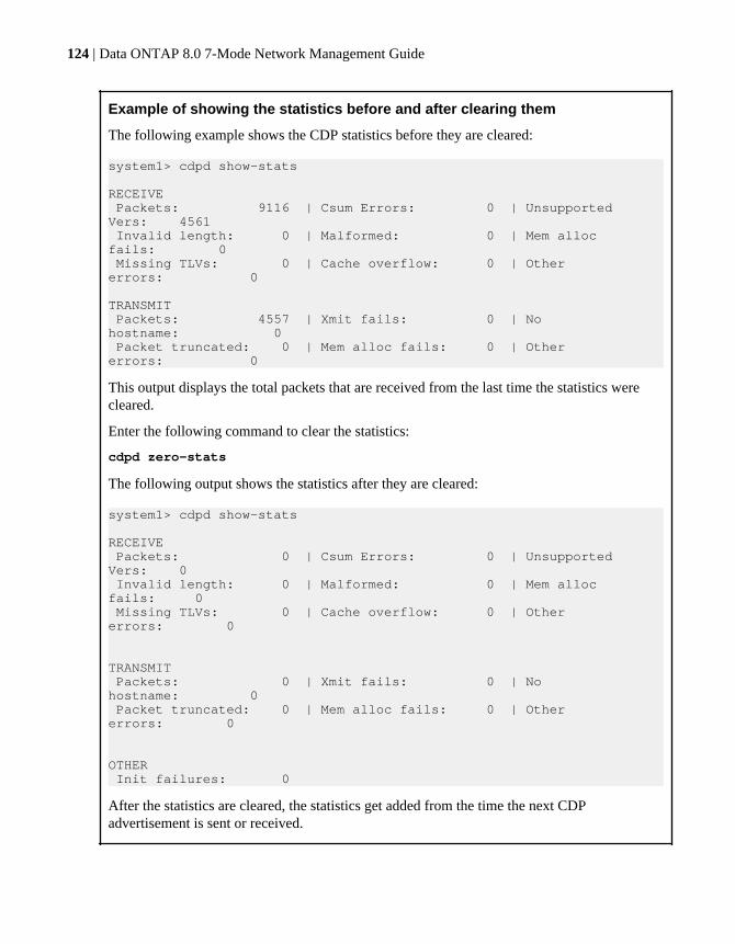
Example of showing the statistics before and after clearing them
The following example shows the CDP statistics before they are cleared:
system1> cdpd show-stats RECEIVE Packets: 9116 | Csum Errors: 0 | Unsupported Vers: 4561 Invalid length: 0 | Malformed: 0 | Mem alloc fails: 0 Missing TLVs: 0 | Cache overflow: 0 | Other errors: 0
TRANSMIT Packets: 4557 | Xmit fails: 0 | No hostname: 0 Packet truncated: 0 | Mem alloc fails: 0 | Other errors: 0
This output displays the total packets that are received from the last time the statistics werecleared.
Enter the following command to clear the statistics:
cdpd zero-stats
The following output shows the statistics after they are cleared:
system1> cdpd show-stats
RECEIVE Packets: 0 | Csum Errors: 0 | Unsupported Vers: 0 Invalid length: 0 | Malformed: 0 | Mem alloc fails: 0 Missing TLVs: 0 | Cache overflow: 0 | Other errors: 0
TRANSMIT Packets: 0 | Xmit fails: 0 | No hostname: 0 Packet truncated: 0 | Mem alloc fails: 0 | Other errors: 0
OTHER Init failures: 0
After the statistics are cleared, the statistics get added from the time the next CDPadvertisement is sent or received.
124 | Data ONTAP 8.0 7-Mode Network Management Guide

Viewing neighbor information by using CDPTo verify your network connectivity, you can view information about the neighboring devicesconnected to each port of your storage system, provided the port is connected to a CDP-compliantdevice. You can use the cdpd show-neighbors command to view neighbor information.
Before you begin
CDP must be enabled on your storage system.
About this task
If a network interface does not have an IP address configured, you can view the CDP information ofthe storage system from the switch. However, you cannot view the CDP information of the switchfrom the storage system.
Step
1. To view information about all CDP-compliant devices connected to your storage system, enterthe following command:
cdpd show-neighbors
Example
The following example shows the output of the cdpd show-neighbors command:
system1> cdpd show-neighborsLocal Remote Remote Remote Hold RemotePort Device Interface Platform Time Capability------ --------------- ---------------------- ---------------- ----- ----------e0a sw-215-cr(4C2) GigabitEthernet1/17 cisco WS-C4948 125 RSIe0b sw-215-11(4C5) GigabitEthernet1/15 cisco WS-C4948 145 SIe0c sw-215-11(4C5) GigabitEthernet1/16 cisco WS-C4948 145 SI
The output lists the Cisco devices that are connected to each port of the storage system. The"Remote Capability" column specifies the capabilities of the remote device that are connectedto the network interface. The following capabilities are available:
• R—Router• T—Transparent bridge• B—Source-route bridge
How CDP works with Data ONTAP | 125

• S—Switch• H—Host• I—IGMP• r—Repeater• P—Phone
126 | Data ONTAP 8.0 7-Mode Network Management Guide
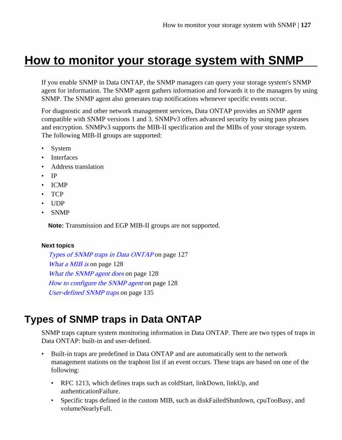
How to monitor your storage system with SNMP
If you enable SNMP in Data ONTAP, the SNMP managers can query your storage system's SNMPagent for information. The SNMP agent gathers information and forwards it to the managers by usingSNMP. The SNMP agent also generates trap notifications whenever specific events occur.
For diagnostic and other network management services, Data ONTAP provides an SNMP agentcompatible with SNMP versions 1 and 3. SNMPv3 offers advanced security by using pass phrasesand encryption. SNMPv3 supports the MIB-II specification and the MIBs of your storage system.The following MIB-II groups are supported:
• System• Interfaces• Address translation• IP• ICMP• TCP• UDP• SNMP
Note: Transmission and EGP MIB-II groups are not supported.
Next topics
Types of SNMP traps in Data ONTAP on page 127
What a MIB is on page 128
What the SNMP agent does on page 128
How to configure the SNMP agent on page 128
User-defined SNMP traps on page 135
Types of SNMP traps in Data ONTAPSNMP traps capture system monitoring information in Data ONTAP. There are two types of traps inData ONTAP: built-in and user-defined.
• Built-in traps are predefined in Data ONTAP and are automatically sent to the networkmanagement stations on the traphost list if an event occurs. These traps are based on one of thefollowing:
• RFC 1213, which defines traps such as coldStart, linkDown, linkUp, andauthenticationFailure.
• Specific traps defined in the custom MIB, such as diskFailedShutdown, cpuTooBusy, andvolumeNearlyFull.
How to monitor your storage system with SNMP | 127

• User-defined traps are defined by snmp traps commands or the FilerView SNMP Trapswindows. These traps are sent using proxy trap ID numbers 11 through 18, which correspond to atrap's MIB priority.
What a MIB isA MIB file is a text file that describes SNMP objects and traps. MIBs are not configuration files.Data ONTAP does not read these files and their contents do not affect SNMP functionality.
Data ONTAP provides two MIB files:
• A custom MIB (/etc/mib/netapp.mib)• An Internet SCSI (iSCSI) MIB (/etc/mib/iscsi.mib)
Data ONTAP also provides a short cross-reference between object identifiers (OIDs) and object shortnames in the /etc/mib/traps.dat file. This file is useful for creating user-defined traps.
Note: The latest versions of the Data ONTAP MIBs and traps.dat files are available online onthe NOW site. However, the versions of these files on the Web site do not necessarily correspondto the SNMP capabilities of your Data ONTAP version. These files are provided to help youevaluate SNMP features in the latest Data ONTAP version.
Related information
NOW site
What the SNMP agent doesThe storage system includes an SNMP agent that responds to queries and sends traps to networkmanagement stations.
The SNMP agent on the storage system has only read privileges—that is, it cannot be used to takecorrective action in response to a trap.
How to configure the SNMP agentYou need to configure the SNMP agent on your storage system to set SNMP values and parameters.You can configure your SNMP agent through the command-line interface or with FilerView.
To configure the SNMP agent on your storage system, you need to perform the following tasks:
• Verify that SNMP is enabled.
Note: SNMP is enabled by default in Data ONTAP.
• If you are running SNMPv3, configure SNMPv3 for read-only access.• Enable traps.
128 | Data ONTAP 8.0 7-Mode Network Management Guide

Although SNMP is enabled by default, traps are disabled by default.• Specify host names of one or more network management stations.
Traps can only be sent when at least one SNMP management station is specified as a traphost.Trap notifications can be sent to a maximum of eight network management stations.
You can perform the following tasks after configuring SNMP:
• Provide courtesy information about storage system location and contact personnel.• Set SNMP access privileges. You can restrict SNMP access on a host or interface basis.• Specify SNMP communities.
Community strings function as group names to establish trust between SNMP managers andclients. Data ONTAP imposes the following limitations on SNMP communities:
• No more than eight communities are allowed.• Only read-only communities are supported.
• Enable query authentication.You can enable authentication failure traps, which are generated when the agent receives querieswith the wrong community string, for the SNMP agent. The traps are sent to all hosts specified astraphosts.
• Create and load user-defined traps.
Note: Storage systems in an HA pair can have different SNMP configurations. For moreinformation, see the na_snmp(1) man page.
Next topics
Enabling or disabling SNMP using the command-line interface on page 130
Configuring SNMPv3 users on page 130
Setting SNMP access privileges on page 131
Viewing or modifying your SNMP configuration from the command-line interface on page 131
Modifying your SNMP configuration from FilerView on page 132
SNMP command syntax on page 132
SNMP security parameters on page 133
Example: SNMP commands on page 134
Related concepts
User-defined SNMP traps on page 135
How to monitor your storage system with SNMP | 129

Enabling or disabling SNMP using the command-line interfaceYou can enable or disable SNMP from the command-line interface by entering the optionssnmp.enable command.
Step
1. Enter the following command:
options snmp.enable {on|off}
on—Enables SNMP
off—Disables SNMP
Configuring SNMPv3 usersTo access MIB objects by using SNMPv3, you should create users with login-snmp capability.
Steps
1. Enter the following command to create a role with login-snmp capability:
useradmin role add role_name -a login-snmp
role_name is the role name with login-snmp capability.
Example
useradmin role add myrole1 -a login-snmp
2. Enter the following command to create a group and add the created role to that group:
useradmin group add group_name -r role_name
group_name is the group name to which you want to add the created role, role_name.
Example
useradmin group add mygroup1 -r myrole1
3. Enter the following command to create a user and add the user to the created group:
useradmin user add user_name -g group_name
user_name is the user name belonging to the group, group_name.
Example
useradmin user add myuser1 -g mygroup1
4. Create a password for the new user.
Ensure that the password has a minimum of eight and a maximum of sixteen characters.
5. Enter the snmpwalk command through the system MIB:
130 | Data ONTAP 8.0 7-Mode Network Management Guide

snmpwalk -v 3 -u user_name -l authNoPriv -A password storage_systemsystem
password is the user's password that you entered in Step 3.
storage_system is the storage system that contains the MIBs.
Example
snmpwalk -v 3 -u myuser1 -l authNoPriv -A johndoe123 host1 system
Setting SNMP access privilegesYou can set SNMP access privileges on a host or an interface by using the command-line interface.The snmp.access option defines a method to restrict access to the storage system on a protocol-by-protocol basis.
About this task
You cannot set access privileges from FilerView.
Step
1. Enter the following command:
options snmp.access access_spec
access_spec consists of keywords and their values. Access can be allowed or restricted by hostname, IP address, and network interface name.
ExampleTo allow access to SNMP for network interfaces e0, e1, and e2, enter the following command:
options snmp.access if=e0,e1,e2
Viewing or modifying your SNMP configuration from the command-lineinterface
You can use the snmp command to view or modify your SNMP configuration values.
Step
1. Enter the following command:
snmp {options values}
options are the available options for the snmp command, such as authtrap, community,contact, init, location, traphost, and traps.
values are the values that you want to set for a particular option.
Related references
SNMP command syntax on page 132
How to monitor your storage system with SNMP | 131

Modifying your SNMP configuration from FilerViewYou can use FilerView to modify your SNMP configuration.
Steps
1. From the list on the left pane, click SNMP > Configure.
The current SNMP configuration is displayed.
2. To set or modify SNMP configuration values, enter configuration values in the drop-down lists ortext fields.
3. Click Apply.
SNMP command syntaxIf you specify one or more values for an option of the SNMP commands, the value of that option isset or changed. However, if no values are specified, the current value of that option is returned.
The following table describes the syntax and parameters of SNMP commands.
Command Description
snmp Displays the current values of all SNMP options, such as init,
community, contact, and traphost.
snmp authtrap [0|1] With a value: Enables (with value 1) or disables (with value 0)authentication failure traps on the SNMP agent.
Without a value: Displays the current value of authtrap set in Data
ONTAP.
snmp community Displays the current list of communities.
snmp community add
rocommunityAdds a community.
Default value: The default community for the SNMP agent in DataONTAP is public. The only access mode available on storage systems isthe default ro (read-only).
snmp community delete
{all | rocommunity }Deletes one or all communities.
snmp contact [contact] With a value: Sets the contact name for your storage system. You mustenclose the contact string in single quotes (' ') if the string contains spaces.
You can enter a maximum of 255 characters for the contact information.
Without a value: Displays the current contact name set in Data ONTAP.
132 | Data ONTAP 8.0 7-Mode Network Management Guide
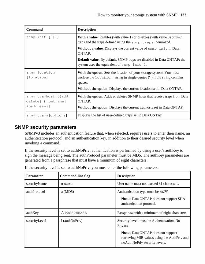
Command Description
snmp init [0|1] With a value: Enables (with value 1) or disables (with value 0) built-intraps and the traps defined using the snmp traps command.
Without a value: Displays the current value of snmp init in Data
ONTAP.
Default value: By default, SNMP traps are disabled in Data ONTAP; thesystem uses the equivalent of snmp init 0.
snmp location
[location]With the option: Sets the location of your storage system. You mustenclose the location string in single quotes (' ') if the string contains
spaces.
Without the option: Displays the current location set in Data ONTAP.
snmp traphost [{add|
delete} { hostname|ipaddress}]
With the option: Adds or deletes SNMP hosts that receive traps from DataONTAP.
Without the option: Displays the current traphosts set in Data ONTAP.
snmp traps [options] Displays the list of user-defined traps set in Data ONTAP
SNMP security parametersSNMPv3 includes an authentication feature that, when selected, requires users to enter their name, anauthentication protocol, and an authentication key, in addition to their desired security level wheninvoking a command.
If the security level is set to authNoPriv, authentication is performed by using a user's authKey tosign the message being sent. The authProtocol parameter must be MD5. The authKey parameters aregenerated from a passphrase that must have a minimum of eight characters.
If the security level is set to authNoPriv, you must enter the following parameters:
Parameter Command-line flag Description
securityName -u Name User name must not exceed 31 characters.
authProtocol -a (MD5) Authentication type must be MD5.
Note: Data ONTAP does not support SHAauthentication protocol.
authKey -A PASSPHRASE Passphrase with a minimum of eight characters.
securityLevel -l (authNoPriv) Security level: must be Authentication, NoPrivacy.
Note: Data ONTAP does not supportretrieving MIB values using the AuthPriv andnoAuthNoPriv security levels.
How to monitor your storage system with SNMP | 133

Parameter Command-line flag Description
context -n CONTEXTNAME Sets the context name used for SNMPv3messages.
Example: SNMP commandsYou can use the snmpget, snmpwalk, snmpbulkget, and snmpbulkwalk commands to retrieveinformation from network elements with SNMP agents.
snmpwalk
The following command retrieves all the variables under the system sys1:
snmpwalk -Os -c public -v 1 sys1 systemsysDescr.0 = STRING: Data ONTAP Release 7.3.1 sysObjectID.0 = OID: enterprises.789.2.3 sysUpTimeInstance = Timeticks: (121596665) 14 days, 1:46:06.65sysContact.0 = STRING: sysName.0 = STRING: sys1.lab.example.com sysLocation.0 = STRING: sysServices.0 = INTEGER: 72
The following command is an example of an SNMPv3 request to retrieve all variables under thesystem sys1:
snmpwalk -v 3 -u joe -l authNoPriv -A joe12 sys1 systemSNMPv2-MIB::sysDescr.0 = STRING: Data ONTAP Release 7.3.1SNMPv2-MIB::sysObjectID.0 = OID:SNMPv2-SMI::enterprises.789.2.3DISMAN-EVENT-MIB::sysUpTimeInstance = Timeticks: (121622059) 14days, 1:50:20.59SNMPv2-MIB::sysContact.0 = STRING: SNMPv2-MIB::sysName.0 = STRING: sys1.lab.example.comSNMPv2-MIB::sysLocation.0 = STRING: SNMPv2-MIB::sysServices.0 = INTEGER: 72
Note: You need to enter authentication information for using SNMPv3.
snmpget
The following command retrieves the system.sysDescr.0 object from the host sys1 by using thepublic community string:
snmpget -c public sys1 system.sysDescr.0system.sysDescr.0 = Data ONTAP Release 8.0 Mon Mar 16 16:56:43 IST 2010
The following command retrieves the value of an ICMP object (OID=56.1.1.1.1) from the host sys1:
134 | Data ONTAP 8.0 7-Mode Network Management Guide
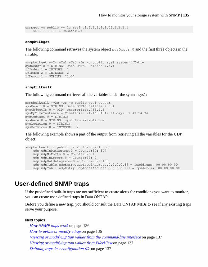
snmpget -c public -v 2c sys1 .1.3.6.1.2.1.56.1.1.1.1 56.1.1.1.1.1 = Counter32: 0
snmpbulkget
The following command retrieves the system object sysDescr.0 and the first three objects in theifTable:
snmpbulkget -v2c -Cn1 -Cr3 -Os -c public sys1 system ifTable sysDescr.0 = STRING: Data ONTAP Release 7.3.1ifIndex.1 = INTEGER: 1ifIndex.2 = INTEGER: 2ifDescr.1 = STRING: "lo0"
snmpbulkwalk
The following command retrieves all the variables under the system sys1:
snmpbulkwalk -v2c -Os -c public sys1 systemsysDescr.0 = STRING: Data ONTAP Release 7.3.1 sysObjectID.0 = OID: enterprises.789.2.3 sysUpTimeInstance = Timeticks: (121603434) 14 days, 1:47:14.34 sysContact.0 = STRING: sysName.0 = STRING: sys1.lab.example.com sysLocation.0 = STRING: sysServices.0 = INTEGER: 72
The following example shows a part of the output from retrieving all the variables for the UDPobject:
snmpbulkwalk -c public -v 2c 192.0.2.19 udp udp.udpInDatagrams.0 = Counter32: 347 udp.udpNoPorts.0 = Counter32: 4 udp.udpInErrors.0 = Counter32: 0 udp.udpOutDatagrams.0 = Counter32: 138 udp.udpTable.udpEntry.udpLocalAddress.0.0.0.0.69 = IpAddress: 00 00 00 00 udp.udpTable.udpEntry.udpLocalAddress.0.0.0.0.111 = IpAddress: 00 00 00 00
User-defined SNMP trapsIf the predefined built-in traps are not sufficient to create alerts for conditions you want to monitor,you can create user-defined traps in Data ONTAP.
Before you define a new trap, you should consult the Data ONTAP MIBs to see if any existing trapsserve your purpose.
Next topics
How SNMP traps work on page 136
How to define or modify a trap on page 136
Viewing or modifying trap values from the command-line interface on page 137
Viewing or modifying trap values from FilerView on page 137
Defining traps in a configuration file on page 137
How to monitor your storage system with SNMP | 135

Example: Trap definitions on page 138
Command syntax for SNMP trap parameters on page 139
SNMP trap parameters on page 139
How SNMP traps workYou can set SNMP traps to inspect the value of MIB variables periodically. Whenever the value of aMIB variable meets the conditions you specify, a trap is sent to the network management stations onthe traphost list. The traphost list specifies the network management stations that receive the trapinformation.
You can set traps on any numeric variable in the MIB. For example, you can set a trap to monitor thefans on your storage system. You can then set the SNMP application on your network managementstation to display a flashing message on your console when a fan stops working.
Traps are persistent across reboots until you remove it or modify it.
Follow these guidelines when creating traps:
• Use the /etc/mib/traps.dat file to find Object Identifiers (OIDs) for objects in the MIB filesof your storage system.
• Ensure that the trap can be generated in the storage system environment.• Do not set traps on tabular data.
It is possible to set traps on row entries in a sequence—for example, an entry in a table. However,if the order in the table is changed by adding or removing rows, you will no longer be trappingthe same numeric variables.
How to define or modify a trapYou can define traps or modify traps you have already defined by entering values from thecommand-line interface, in FilerView, or in a configuration file.
You must supply the following elements when you create or modify traps:
• Trap nameTrap name is the name of the user-defined trap you want to create or change. A trap name mustnot have any embedded periods.
• Trap parameters• Parameter values
Note: When you create a user-defined trap, it is initially disabled by default. You must enable atrap before it can be triggered. You enable traps by using the snmp traps command orFilerView.
136 | Data ONTAP 8.0 7-Mode Network Management Guide

Viewing or modifying trap values from the command-line interfaceYou can view or modify your trap values by using the snmp traps command.
Step
1. Enter the following command:
snmp traps {options variables}
options are the options for SNMP traps such as walk, load, trapname, and so on.
variables are values for the specified option.
Viewing or modifying trap values from FilerViewYou can use FilerView to view or modify a trap value.
Steps
1. From the list on the left pane, click SNMP > Traps.
2. Depending on whether you want to create, modify, or view a trap, perform the following step:
If you want to... Then...
Create a new trap a. Click Add.
b. In the Add an SNMP Trap window, enter the requested information.
c. Click Add again.
View or modify an existingtrap
a. Click Manage for the trap you want to view or modify.
b. To modify the trap, click Modify in the Manage SNMP Traps window.
Defining traps in a configuration fileYou can define SNMP traps in a configuration file and then load the file with the snmp trapsload command. Data ONTAP automatically backs up your SNMP configuration as Snapshot copies,making it easy to transfer user-defined traps to other storage systems and to recover SNMPconfigurations in case of a disaster.
Steps
1. Create a traps configuration file on your storage system.
You can choose the name and location of the file.
Example/etc/mib/mytraps
How to monitor your storage system with SNMP | 137
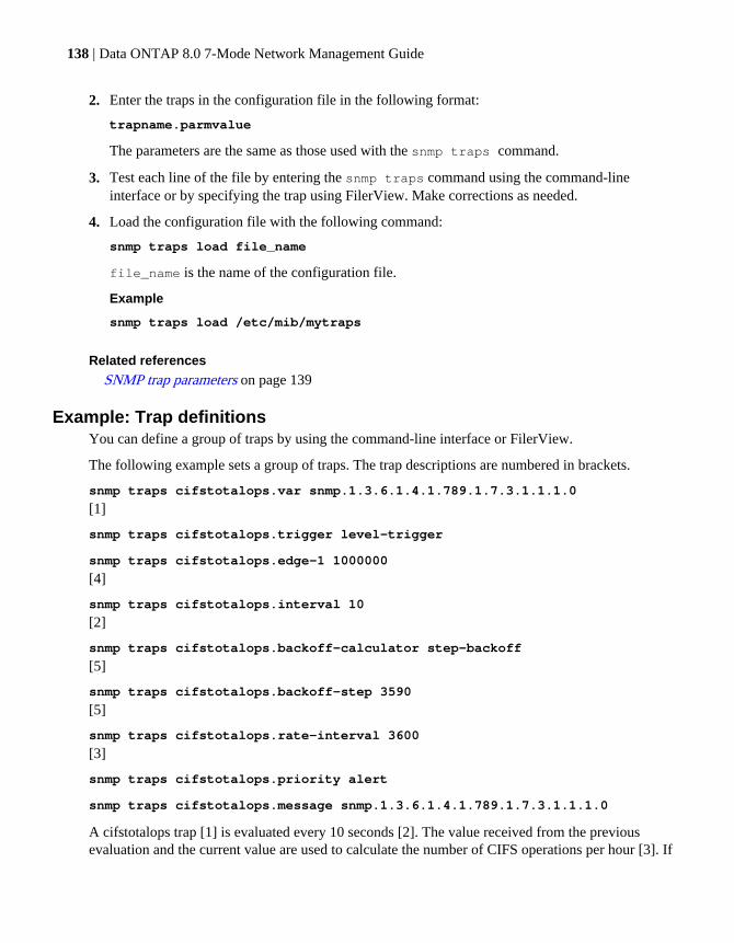
2. Enter the traps in the configuration file in the following format:
trapname.parmvalue
The parameters are the same as those used with the snmp traps command.
3. Test each line of the file by entering the snmp traps command using the command-lineinterface or by specifying the trap using FilerView. Make corrections as needed.
4. Load the configuration file with the following command:
snmp traps load file_name
file_name is the name of the configuration file.
Example
snmp traps load /etc/mib/mytraps
Related references
SNMP trap parameters on page 139
Example: Trap definitionsYou can define a group of traps by using the command-line interface or FilerView.
The following example sets a group of traps. The trap descriptions are numbered in brackets.
snmp traps cifstotalops.var snmp.1.3.6.1.4.1.789.1.7.3.1.1.1.0
[1]
snmp traps cifstotalops.trigger level-trigger
snmp traps cifstotalops.edge-1 1000000
[4]
snmp traps cifstotalops.interval 10
[2]
snmp traps cifstotalops.backoff-calculator step-backoff
[5]
snmp traps cifstotalops.backoff-step 3590
[5]
snmp traps cifstotalops.rate-interval 3600
[3]
snmp traps cifstotalops.priority alert
snmp traps cifstotalops.message snmp.1.3.6.1.4.1.789.1.7.3.1.1.1.0
A cifstotalops trap [1] is evaluated every 10 seconds [2]. The value received from the previousevaluation and the current value are used to calculate the number of CIFS operations per hour [3]. If
138 | Data ONTAP 8.0 7-Mode Network Management Guide
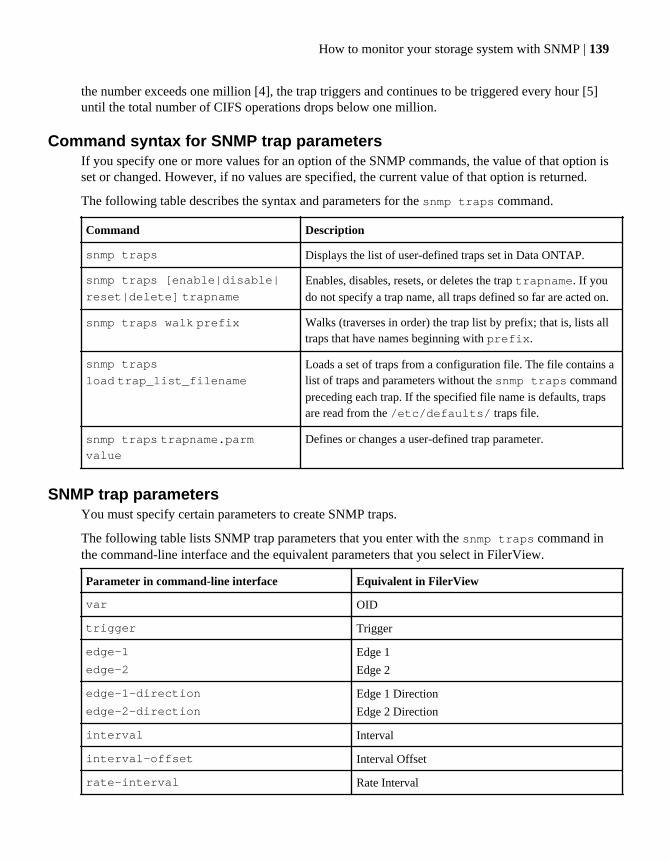
the number exceeds one million [4], the trap triggers and continues to be triggered every hour [5]until the total number of CIFS operations drops below one million.
Command syntax for SNMP trap parametersIf you specify one or more values for an option of the SNMP commands, the value of that option isset or changed. However, if no values are specified, the current value of that option is returned.
The following table describes the syntax and parameters for the snmp traps command.
Command Description
snmp traps Displays the list of user-defined traps set in Data ONTAP.
snmp traps [enable|disable|
reset|delete] trapnameEnables, disables, resets, or deletes the trap trapname. If you
do not specify a trap name, all traps defined so far are acted on.
snmp traps walk prefix Walks (traverses in order) the trap list by prefix; that is, lists alltraps that have names beginning with prefix.
snmp traps
load trap_list_filenameLoads a set of traps from a configuration file. The file contains alist of traps and parameters without the snmp traps command
preceding each trap. If the specified file name is defaults, trapsare read from the /etc/defaults/ traps file.
snmp traps trapname.parmvalue
Defines or changes a user-defined trap parameter.
SNMP trap parametersYou must specify certain parameters to create SNMP traps.
The following table lists SNMP trap parameters that you enter with the snmp traps command inthe command-line interface and the equivalent parameters that you select in FilerView.
Parameter in command-line interface Equivalent in FilerView
var OID
trigger Trigger
edge-1
edge-2
Edge 1
Edge 2
edge-1-direction
edge-2-direction
Edge 1 Direction
Edge 2 Direction
interval Interval
interval-offset Interval Offset
rate-interval Rate Interval
How to monitor your storage system with SNMP | 139
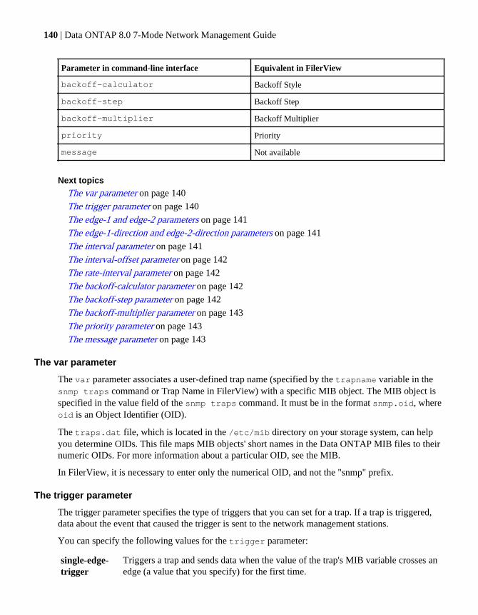
Parameter in command-line interface Equivalent in FilerView
backoff-calculator Backoff Style
backoff-step Backoff Step
backoff-multiplier Backoff Multiplier
priority Priority
message Not available
Next topics
The var parameter on page 140
The trigger parameter on page 140
The edge-1 and edge-2 parameters on page 141
The edge-1-direction and edge-2-direction parameters on page 141
The interval parameter on page 141
The interval-offset parameter on page 142
The rate-interval parameter on page 142
The backoff-calculator parameter on page 142
The backoff-step parameter on page 142
The backoff-multiplier parameter on page 143
The priority parameter on page 143
The message parameter on page 143
The var parameter
The var parameter associates a user-defined trap name (specified by the trapname variable in thesnmp traps command or Trap Name in FilerView) with a specific MIB object. The MIB object isspecified in the value field of the snmp traps command. It must be in the format snmp.oid, whereoid is an Object Identifier (OID).
The traps.dat file, which is located in the /etc/mib directory on your storage system, can helpyou determine OIDs. This file maps MIB objects' short names in the Data ONTAP MIB files to theirnumeric OIDs. For more information about a particular OID, see the MIB.
In FilerView, it is necessary to enter only the numerical OID, and not the "snmp" prefix.
The trigger parameter
The trigger parameter specifies the type of triggers that you can set for a trap. If a trap is triggered,data about the event that caused the trigger is sent to the network management stations.
You can specify the following values for the trigger parameter:
single-edge-trigger
Triggers a trap and sends data when the value of the trap's MIB variable crosses anedge (a value that you specify) for the first time.
140 | Data ONTAP 8.0 7-Mode Network Management Guide

double-edge-trigger
Triggers a trap and sends data when either of two edges is crossed. A double-edge-trigger enables you to set two edges, each with its own direction.
level-trigger Triggers a trap and sends data whenever the trap's value crosses a specified edgevalue.
change-trigger
Keeps track of the last value received from the trap. If the current value differsfrom the previously received value, the trap is triggered.
always-trigger
Enables a trap to always trigger at the specified evaluation interval (specified bythe interval parameter). For example, a trap can trigger every 24 hours for theagent to send the total number of CIFS operations to an SNMP manager.
The edge-1 and edge-2 parameters
The edge-1 and edge-2 parameters of a trap specify the threshold values that are compared duringtrap evaluation to determine whether to fire a trap and send data.
The edge-1 parameter specifies the value for the edge in a single-edge-triggered trap or the first edgein a double-edge-triggered trap. The default value for the edge-1 parameter is MAXINT.
The edge-2 parameter specifies the value for the second edge in a double-edge-triggered trap. Thedefault value for the edge-2 parameter is 0.
Note: The edge-2 parameter is not displayed in FilerView during trap creation unless double-edge-trigger is selected in the trigger parameter.
The edge-1-direction and edge-2-direction parameters
The edge-1-direction and edge-2-direction parameters enable you to set or change the direction thatis used to evaluate a trap. The edge-triggered traps only send data when the edge is crossed in eitherthe up or down direction.
The default value for the edge-1-direction parameter is up and for the edge-2-direction parameter isdown.
Note: You enter the direction values on the same line as the edge value when you run the snmptraps command. The edge-2-direction parameter is not displayed in FilerView during trapcreation unless double-edge-trigger is selected in the trigger parameter.
The interval parameter
The interval parameter is the time, in seconds, between evaluations of a trap.
A trap can only send data as often as it is evaluated, even if the edge values are exceeded sooner. Thedefault value for the interval parameter is 3600.
Note: The maximum value that can be specified for the interval parameter in Data ONTAP is2147482 seconds, which is approximately equal to 24 days.
How to monitor your storage system with SNMP | 141

The interval-offset parameter
The interval-offset parameter is the amount of time, in seconds, until the first trap evaluation.
The default value for the interval-offset parameter is 0. You can set it to a nonzero value toprevent too many traps from being evaluated at once (for example, at system startup).
The rate-interval parameter
The rate-interval parameter specifies the time, in seconds, in which the change in value of atrap's variable (rate of change) is expressed.
If the rate-interval value is set for a trap, the samples of data obtained at the interval points (setusing the interval parameter) for a trap variable are used to calculate the rate of change. If thecalculated value exceeds the value set for the edge-1 or edge-2 parameter, the trap is fired.
For example, to obtain the number of CIFS operations per hour, you specify a rate-interval of3600. If rate-interval is set to 0, no sampling at interval points occurs and trap evaluationproceeds as with any other kind of trap. The default value for the rate-interval parameter is 0.
The backoff-calculator parameter
The backoff-calculator parameter enables you to change the trap evaluation interval for a trapafter a trap fires.
After a trap fires and sends data, you might not want it to be evaluated so often. For instance, youmight want to know within a minute of when a file system is full, but only want to be notified everyhour thereafter that it is still full.
The backoff-calculator parameter can take the following values in the value variable field:
• step-backoff
• exponential-backoff
• no-backoff
The default value for the backoff-calculator parameter is no-backoff.
The backoff-step parameter
The backoff-step parameter specifies the number of seconds by which the trap evaluation intervalis increased.
If a trap interval is 10 and its backoff-step is 3590, the trap is evaluated every 10 seconds until it firesthe first time and sends data, and once an hour thereafter. The default value for the backoff-stepparameter is 0.
Note: The backoff step parameter is not displayed in FilerView during trap creation unless"step" is selected in the Backoff Style field.
142 | Data ONTAP 8.0 7-Mode Network Management Guide
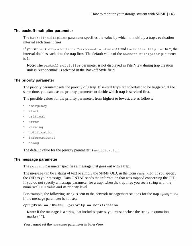
The backoff-multiplier parameter
The backoff-multiplier parameter specifies the value by which to multiply a trap's evaluationinterval each time it fires.
If you set backoff-calculator to exponential-backoff and backoff-multiplier to 2, theinterval doubles each time the trap fires. The default value of the backoff-multiplier parameteris 1.
Note: The backoff multiplier parameter is not displayed in FilerView during trap creationunless "exponential" is selected in the Backoff Style field.
The priority parameter
The priority parameter sets the priority of a trap. If several traps are scheduled to be triggered at thesame time, you can use the priority parameter to decide which trap is serviced first.
The possible values for the priority parameter, from highest to lowest, are as follows:
• emergency
• alert
• critical
• error
• warning
• notification
• informational
• debug
The default value for the priority parameter is notification.
The message parameter
The message parameter specifies a message that goes out with a trap.
The message can be a string of text or simply the SNMP OID, in the form snmp.oid. If you specifythe OID as your message, Data ONTAP sends the information that was trapped concerning the OID.If you do not specify a message parameter for a trap, when the trap fires you see a string with thenumerical OID value and its priority level.
For example, the following string is sent to the network management stations for the trap cpuUpTimeif the message parameter is not set:
cpuUpTime == 10562288.priority == notification
Note: If the message is a string that includes spaces, you must enclose the string in quotationmarks (" ").
You cannot set the message parameter in FilerView.
How to monitor your storage system with SNMP | 143


How to diagnose network problems
You can diagnose problems on your network by using commands such as cdpd, netdiag, ping,and pktt.
cdpd You can use the cdpd command to view information about the devices that advertisethemselves by using the CDPv1 protocol. You can also view information about the CDPneighbors of the storage system and thus detect network connectivity.
netdiag You can use the netdiag command to continuously gather and analyze statistics, andperform diagnostic tests. These diagnostic tests identify and report problems with yourphysical network or transport layers and suggest remedial action.
For more information about the netdiag command along with all available options, seethe na_netdiag(1) man page.
ping You can use the ping command to test whether your storage system can reach otherhosts on your network.
For more information about the ping command, see the na_ping(1) man page.
pktt You can use the pktt command to trace the packets sent and received in the storagesystem's network.
For more information about the pktt command, see the na_pktt(1) man page.
Next topics
Diagnosing transport layer problems on page 145
Viewing diagnostic results on page 146
How to diagnose ping problems on page 146
Protecting your storage system from forged ICMP redirect attacks on page 148
Related references
Error codes for the netdiag command on page 181
Diagnosing transport layer problemsYou can use the netdiag -t command to diagnose problems with the transport layer in yourstorage system.
Step
1. Enter the following command:
How to diagnose network problems | 145

netdiag -t
Example
A storage system whose TCP window size is smaller than the recommended value displays thefollowing output:
Performing transport layer diagnostics.....The TCP receive window advertised by CIFS client192.0.2.13 is 8760. This is less than the recommended value of 32768 bytes. You should increase the TCP receivebuffer size for CIFS on the client. Press enter to continue.
Viewing diagnostic resultsYou can use the netdiag -s command to view a summary of the various diagnostic checks andtests performed on your storage system.
Step
1. Enter the following command:
netdiag -s
How to diagnose ping problemsYou can use the Data ONTAP ping throttling mechanism and its ip.ping_throttle.drop_leveloption to help avoid denial-of-service attacks that can occur when using ICMP.
The ping throttling mechanism is active in intervals of 1 second. If the number of ICMP echo andreply packets that the storage system receives in a one-second interval exceeds the ping throttlingthreshold, the storage system drops all subsequent packets that are received within that one-secondinterval.
Note: Regardless of whether the ping throttling threshold has been reached, clients that send morethan 16 packets per second to a storage system might experience packet loss. To allow clients tosend more than 16 packets per second, you must disable ping throttling.
If your storage system supports a very large number of CIFS clients that use ICMP pings todetermine CIFS shares accessibility, you can increase the ping throttling threshold value in theip.ping_throttle.drop_level option.
If a large number of CIFS clients are experiencing temporary or persistent unavailability of thestorage system, you should check to see if the ping throttling threshold has been exceeded for thestorage system. If so, you can increase the ping throttling threshold value.
146 | Data ONTAP 8.0 7-Mode Network Management Guide
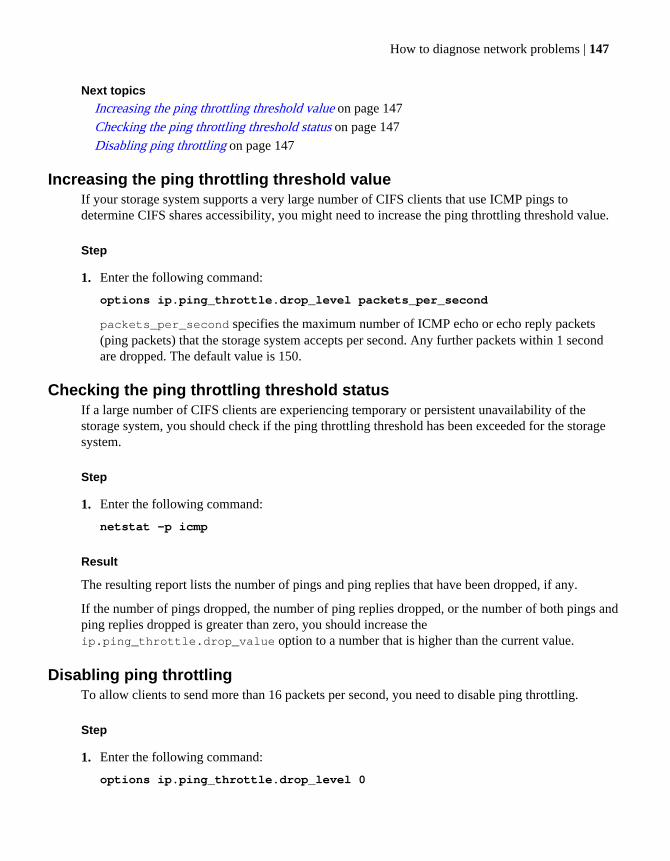
Next topics
Increasing the ping throttling threshold value on page 147
Checking the ping throttling threshold status on page 147
Disabling ping throttling on page 147
Increasing the ping throttling threshold valueIf your storage system supports a very large number of CIFS clients that use ICMP pings todetermine CIFS shares accessibility, you might need to increase the ping throttling threshold value.
Step
1. Enter the following command:
options ip.ping_throttle.drop_level packets_per_second
packets_per_second specifies the maximum number of ICMP echo or echo reply packets(ping packets) that the storage system accepts per second. Any further packets within 1 secondare dropped. The default value is 150.
Checking the ping throttling threshold statusIf a large number of CIFS clients are experiencing temporary or persistent unavailability of thestorage system, you should check if the ping throttling threshold has been exceeded for the storagesystem.
Step
1. Enter the following command:
netstat -p icmp
Result
The resulting report lists the number of pings and ping replies that have been dropped, if any.
If the number of pings dropped, the number of ping replies dropped, or the number of both pings andping replies dropped is greater than zero, you should increase theip.ping_throttle.drop_value option to a number that is higher than the current value.
Disabling ping throttlingTo allow clients to send more than 16 packets per second, you need to disable ping throttling.
Step
1. Enter the following command:
options ip.ping_throttle.drop_level 0
How to diagnose network problems | 147
Protecting your storage system from forged ICMP redirectattacks
You can disable ICMP redirect messages to protect your storage system against forged ICMPredirect attacks.
About this task
To efficiently route a series of datagrams to the same destination, your storage system maintains aroute cache of mappings to next-hop gateways. If a gateway is not the best next-hop for a datagramwith a specific destination, the gateway forwards the datagram to the best next-hop gateway andsends an ICMP redirect message to the storage system. By forging ICMP redirect messages, anattacker can modify the route cache on your storage system, causing it to send all of itscommunications through the attacker. The attacker can then hijack a session at the network level,easily monitoring, modifying, and injecting data into the session.
Step
1. Enter the following command:
options ip.icmp_ignore_redirect.enable on
Your storage system now ignores ICMP redirect messages.
For more information about the ip.icmp_ignore_redirect.enable option, see thena_options(1) man page.
Note: By default, the ip.icmp_ignore_redirect.enable option is off.
148 | Data ONTAP 8.0 7-Mode Network Management Guide

Network interface statistics
You can use the ifstat command to view statistics for the network interfaces supported by DataONTAP. To determine the Ethernet controllers in your system, you can use the sysconfigcommand.
Next topics
Statistics for Gigabit Ethernet controller VI, VII, and G20 interfaces on page 149
Statistics for Gigabit and 10 Gigabit Ethernet controllers T204, T210, and T320interfaces on page 153
Statistics for the BGE 10/100/1000 Ethernet interface on page 156
Statistics for 10 Gigabit Ethernet Controller IX1 - SFP+ on page 159
Statistics for Dual 10G Ethernet Controller CNA - SFP+ on page 162
Statistics for Gigabit Ethernet controller VI, VII, and G20interfaces
The ifstat command output displays several statistics when you use the command for the GigabitEthernet controllers and G20 interfaces.
The statistics in this section are for the following controllers:
• 10/100/1000 Ethernet controller VI and VII• Gigabit Ethernet controller VI• 10/100/1000 Ethernet controller G20• Gigabit Ethernet controller G20
RECEIVE section statistics
The following table describes the statistics in the RECEIVE section of the ifstat command output.
Statistic Definition
Frames/second Rate of received frames per second.
Bytes/second Rate of received bytes per second.
Errors/minute Rate of errors (which led to frames being lost) per minute.
Discards/minute Rate per minute of packets discarded due to unavailable resources.
Total frames Total frames that are received on the interface.
Total bytes Total bytes that are received on the interface.
Network interface statistics | 149

Statistic Definition
Total errors Total errors that occur on the interface.
Total discards Total number of packets that were discarded even though no errorswere detected. This number is a sum of the "No buffers", "Busoverruns", and "Queue overflows" statistics.
Multi/broadcast Total number of multicast or broadcast packets received.
Alignment errors Number of frames that are both misaligned and contain CRC errors.
Non-primary u/c Number of Ethernet frames received for the partner's MAC addressafter a failover in an HA pair.
Tag drop Number of tagged frames dropped on an interface that is notconfigured to support VLAN tagging.
Vlan tag drop Number of tagged frames dropped that do not match the VLAN tagsconfigured on the interface.
Vlan untag drop Number of untagged frames dropped on an interface that is configuredto be part of a VLAN.
CRC errors Number of packets received with bad CRC.
Bad length Total number of received packets with a bad length. These are framescounted as undersize, fragment, oversize, or jabber.
Runt frames Number of received frames that were less than the minimum size (64bytes) and had a valid CRC.
Fragment Number of received frames that were less than the minimum size andhad a bad CRC.
Long frames Number of received frames that were greater than the maximum sizeand had a valid CRC.
Jabber Number of received frames that were greater than the maximum sizeand had a bad CRC.
Bus overruns Number of times the adapter's receive FIFO overflowed and a packetwas dropped. This occurs when the bus is very busy and the adaptercannot transfer data into host memory. This might also occur whenyour storage system CPU is very busy and cannot process the receivedpackets fast enough.
Queue overflows Number of frames dropped on receive due to the driver receive queueoverflowing.
150 | Data ONTAP 8.0 7-Mode Network Management Guide

Statistic Definition
No buffer Number of times the driver could not allocate a buffer and a packetwas dropped. This might happen when your storage system is verybusy. If the count increases continually, it might indicate that asoftware component is not returning buffers.
Xon Number of XON frames received when receive or full flow control isenabled.
Xoff Number of XOFF frames received when receive or full flow control isenabled.
Jumbo Number of good packets received that were larger than the standardEthernet packet size when jumbo frames are enabled.
Reset Number of times the driver reset the NIC because the NIC was in abad state.
Reset1 Number of times the driver reset the NIC because the NIC was in abad state.
Reset2 Number of times the driver reset the NIC because the NIC was in abad state.
TRANSMIT section statistics
The following table describes the statistics in the TRANSMIT section of the ifstat commandoutput.
Statistic Meaning
Frames/second Rate of transmitted frames per second.
Bytes/second Rate of transmitted bytes per second.
Errors/minute Rate of errors (which led to frames being lost) per minute.
Discards/minute Rate per minute of packets discarded due to unavailable resources.
Total frames Total frames that are transmitted on the interface.
Total bytes Total bytes that are transmitted on the interface.
Total errors Total errors that occur on the interface.
Total discards Total number of packets that were discarded even though no errorswere detected. This number is a sum of the "No buffers" and "Queueoverflows" statistics.
Multi/broadcast Total number of multicast or broadcast packets transmitted.
Network interface statistics | 151
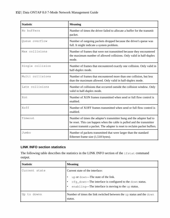
Statistic Meaning
No buffers Number of times the driver failed to allocate a buffer for the transmitpacket.
Queue overflow Number of outgoing packets dropped because the driver's queue wasfull. It might indicate a system problem.
Max collisions Number of frames that were not transmitted because they encounteredthe maximum number of allowed collisions. Only valid in half-duplexmode.
Single collision Number of frames that encountered exactly one collision. Only valid inhalf-duplex mode.
Multi collisions Number of frames that encountered more than one collision, but lessthan the maximum allowed. Only valid in half-duplex mode.
Late collisions Number of collisions that occurred outside the collision window. Onlyvalid in half-duplex mode.
Xon Number of XON frames transmitted when send or full flow control isenabled.
Xoff Number of XOFF frames transmitted when send or full flow control isenabled.
Timeout Number of times the adapter's transmitter hung and the adapter had tobe reset. This can happen when the cable is pulled and the transmittercannot transmit a packet. The adapter is reset to reclaim packet buffers.
Jumbo Number of packets transmitted that were larger than the standardEthernet frame size (1,518 bytes).
LINK INFO section statistics
The following table describes the statistics in the LINK INFO section of the ifstat commandoutput.
Statistic Meaning
Current state Current state of the interface:
• up or down—The state of the link.
• cfg_down—The interface is configured to the down status.
• enabling—The interface is moving to the up status.
Up to downs Number of times the link switched between the up status and the down
status.
152 | Data ONTAP 8.0 7-Mode Network Management Guide

Statistic Meaning
Auto Operational state of autonegotiation:
• on—Autonegotiation is enabled and succeeded.
• off—Autonegotiation failed. This happens when the device to
which the interface is connected has disabled autonegotiation or isincompatible with the interface. This might also indicate that theinterface is in the down status.
Speed Speed of link negotiated or set.
Duplex Duplex of the link negotiated or set.
Flow control The operational flow control setting.
Related tasks
Viewing or clearing network interface statistics on page 46
Statistics for Gigabit and 10 Gigabit Ethernet controllersT204, T210, and T320 interfaces
The ifstat command output displays several statistics when you use the command for the10/100/1000 Ethernet controllers T204V and T204E, and the 10 Gigabit Ethernet controllers T210and T320.
RECEIVE section statistics
The following table describes the statistics in the RECEIVE section of the ifstat command outputwhen you use the command on the 10/100/1000 Ethernet controllers T204V and T204E, and the 10Gigabit Ethernet controllers T210 and T320.
Statistic Meaning
Frames/second Rate of received frames per second.
Bytes/second Rate of received bytes per second.
Errors/minute Rate of errors (which led to frames being lost) per minute.
Discards/minute Rate per minute of packets discarded due to unavailable resources.
Total frames Total frames that are received on the interface.
Total bytes Total bytes that are received on the interface.
Total errors Total errors that occur on the interface.
Network interface statistics | 153

Statistic Meaning
Total discards Total number of packets that were discarded even though no errorswere detected. This number is a sum of the "No buffers", "Busoverruns", and "Queue overflows" statistics.
Multi/broadcast Total number of multicast or broadcast packets received.
Alignment errors Number of frames that are both misaligned and contain CRC errors.
Non-primary u/c Number of Ethernet frames received for the partner's MAC addressafter a failover in an HA pair.
Tag drop Number of tagged frames dropped on an interface that is notconfigured to support VLAN tagging.
Vlan tag drop Number of tagged frames dropped that do not match the VLAN tagsconfigured on the interface.
Vlan untag drop Number of untagged frames dropped on an interface that isconfigured to be part of a VLAN.
CRC errors Number of packets received with bad CRC.
Runt frames Number of received frames that were less than the minimum size (64bytes) and had a valid CRC.
Long frames Number of received frames that were greater than the maximum sizeand had a valid CRC.
Jabber Number of received frames that were greater than the maximum sizeand had a bad CRC.
No buffer Number of times the driver could not allocate a buffer and a packetwas dropped. This might happen when your storage system is verybusy. If the count increases continually, it might indicate that asoftware component is not returning buffers.
Jumbo Number of good packets received that were larger than the standardEthernet packet size when jumbo frames are enabled.
Pause Frames Number of MAC Control PAUSE frames sent to the link partner toinhibit transmission of data frames for a specified period of time. Thiscan help the partner from overrunning the controller's receive buffers.
TRANSMIT section statistics
The following table describes the statistics in the TRANSMIT section of the ifstat commandoutput when you use the command on the 10/100/1000 Ethernet controllers T204V and T204E, andthe 10 Gigabit Ethernet controllers T210 and T320.
154 | Data ONTAP 8.0 7-Mode Network Management Guide
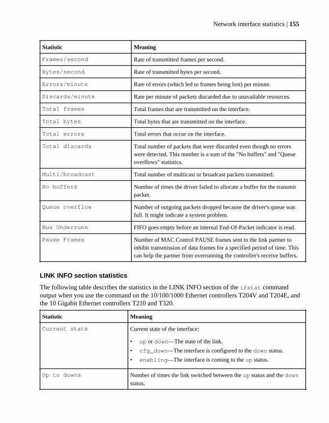
Statistic Meaning
Frames/second Rate of transmitted frames per second.
Bytes/second Rate of transmitted bytes per second.
Errors/minute Rate of errors (which led to frames being lost) per minute.
Discards/minute Rate per minute of packets discarded due to unavailable resources.
Total frames Total frames that are transmitted on the interface.
Total bytes Total bytes that are transmitted on the interface.
Total errors Total errors that occur on the interface.
Total discards Total number of packets that were discarded even though no errorswere detected. This number is a sum of the "No buffers" and "Queueoverflows" statistics.
Multi/broadcast Total number of multicast or broadcast packets transmitted.
No buffers Number of times the driver failed to allocate a buffer for the transmitpacket.
Queue overflow Number of outgoing packets dropped because the driver's queue wasfull. It might indicate a system problem.
Bus Underruns FIFO goes empty before an internal End-Of-Packet indicator is read.
Pause Frames Number of MAC Control PAUSE frames sent to the link partner toinhibit transmission of data frames for a specified period of time. Thiscan help the partner from overrunning the controller's receive buffers.
LINK INFO section statistics
The following table describes the statistics in the LINK INFO section of the ifstat commandoutput when you use the command on the 10/100/1000 Ethernet controllers T204V and T204E, andthe 10 Gigabit Ethernet controllers T210 and T320.
Statistic Meaning
Current state Current state of the interface:
• up or down—The state of the link.
• cfg_down—The interface is configured to the down status.
• enabling—The interface is coming to the up status.
Up to downs Number of times the link switched between the up status and the down
status.
Network interface statistics | 155
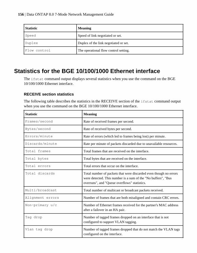
Statistic Meaning
Speed Speed of link negotiated or set.
Duplex Duplex of the link negotiated or set.
Flow control The operational flow control setting.
Statistics for the BGE 10/100/1000 Ethernet interfaceThe ifstat command output displays several statistics when you use the command on the BGE10/100/1000 Ethernet interface.
RECEIVE section statistics
The following table describes the statistics in the RECEIVE section of the ifstat command outputwhen you use the command on the BGE 10/100/1000 Ethernet interface.
Statistic Meaning
Frames/second Rate of received frames per second.
Bytes/second Rate of received bytes per second.
Errors/minute Rate of errors (which led to frames being lost) per minute.
Discards/minute Rate per minute of packets discarded due to unavailable resources.
Total frames Total frames that are received on the interface.
Total bytes Total bytes that are received on the interface.
Total errors Total errors that occur on the interface.
Total discards Total number of packets that were discarded even though no errorswere detected. This number is a sum of the "No buffers", "Busoverruns", and "Queue overflows" statistics.
Multi/broadcast Total number of multicast or broadcast packets received.
Alignment errors Number of frames that are both misaligned and contain CRC errors.
Non-primary u/c Number of Ethernet frames received for the partner's MAC addressafter a failover in an HA pair.
Tag drop Number of tagged frames dropped on an interface that is notconfigured to support VLAN tagging.
Vlan tag drop Number of tagged frames dropped that do not match the VLAN tagsconfigured on the interface.
156 | Data ONTAP 8.0 7-Mode Network Management Guide
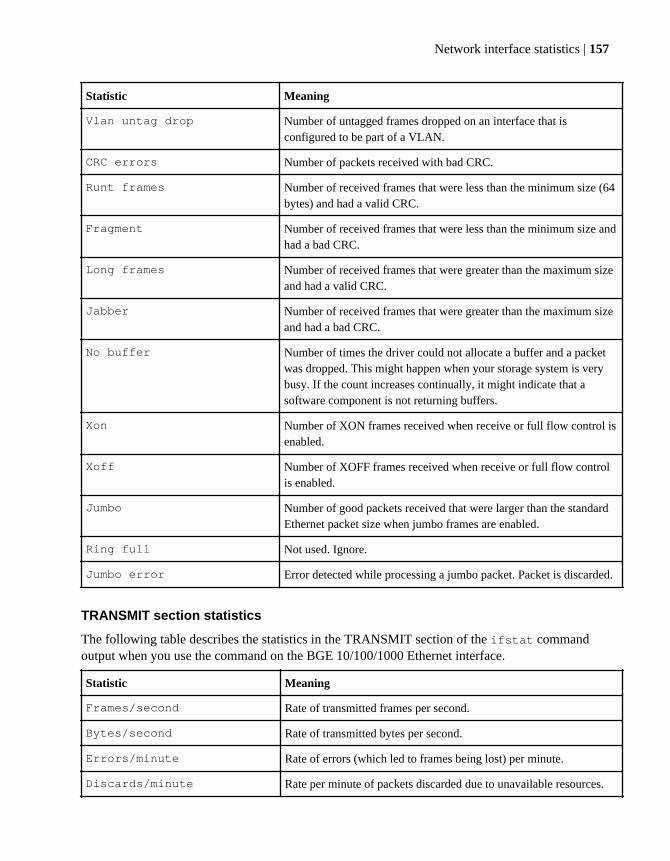
Statistic Meaning
Vlan untag drop Number of untagged frames dropped on an interface that isconfigured to be part of a VLAN.
CRC errors Number of packets received with bad CRC.
Runt frames Number of received frames that were less than the minimum size (64bytes) and had a valid CRC.
Fragment Number of received frames that were less than the minimum size andhad a bad CRC.
Long frames Number of received frames that were greater than the maximum sizeand had a valid CRC.
Jabber Number of received frames that were greater than the maximum sizeand had a bad CRC.
No buffer Number of times the driver could not allocate a buffer and a packetwas dropped. This might happen when your storage system is verybusy. If the count increases continually, it might indicate that asoftware component is not returning buffers.
Xon Number of XON frames received when receive or full flow control isenabled.
Xoff Number of XOFF frames received when receive or full flow controlis enabled.
Jumbo Number of good packets received that were larger than the standardEthernet packet size when jumbo frames are enabled.
Ring full Not used. Ignore.
Jumbo error Error detected while processing a jumbo packet. Packet is discarded.
TRANSMIT section statistics
The following table describes the statistics in the TRANSMIT section of the ifstat commandoutput when you use the command on the BGE 10/100/1000 Ethernet interface.
Statistic Meaning
Frames/second Rate of transmitted frames per second.
Bytes/second Rate of transmitted bytes per second.
Errors/minute Rate of errors (which led to frames being lost) per minute.
Discards/minute Rate per minute of packets discarded due to unavailable resources.
Network interface statistics | 157

Statistic Meaning
Total frames Total frames that are transmitted on the interface.
Total bytes Total bytes that are transmitted on the interface.
Total errors Total errors that occur on the interface.
Total discards Total number of packets that were discarded even though no errorswere detected. This number is a sum of the "No buffers" and "Queueoverflows" statistics.
Multi/broadcast Total number of multicast or broadcast packets transmitted.
No buffers Number of times the driver failed to allocate a buffer for the transmitpacket.
Queue overflow Number of outgoing packets dropped because the driver's queue wasfull. It might indicate a system problem.
Max collisions Number of frames that were not transmitted because theyencountered the maximum number of allowed collisions. Only validin half-duplex mode.
Single collision Number of frames that encountered exactly one collision. Only validin half-duplex mode.
Multi collisions Number of frames that encountered more than one collision, but lessthan the maximum allowed. Only valid in half-duplex mode.
Late collisions Number of collisions that occurred outside the collision window.Only valid in half-duplex mode.
Xon Number of XON frames transmitted when send or full flow control isenabled.
Xoff Number of XOFF frames transmitted when send or full flow controlis enabled.
Jumbo Number of packets transmitted that were larger than the standardEthernet packet size when jumbo frames are enabled.
Deferred Number of frames for which the first transmission was delayedbecause the medium was busy.
MAC Internal Number of frames not transmitted due to an internal MAC sublayererror.
LINK INFO section statistics
The following table describes the statistics in the LINK INFO section of the ifstat commandoutput when you use the command on the BGE 10/100/1000 Ethernet interface.
158 | Data ONTAP 8.0 7-Mode Network Management Guide

Statistic Meaning
Current state Current state of the interface:
• up or down—The state of the link.
• cfg_down—The interface is configured to the down status.
• enabling—The interface is coming to the up status.
Up to downs Number of times the link switched between the up status and the down
status.
Speed Speed of link negotiated or set.
Duplex Duplex of the link negotiated or set.
Flow control The operational flow control setting.
Related tasks
Viewing or clearing network interface statistics on page 46
Statistics for 10 Gigabit Ethernet Controller IX1 - SFP+The ifstat command output displays several statistics when you use the command for the 10Gigabit Ethernet controllers.
RECEIVE section statistics
The following table describes the statistics in the RECEIVE section of the ifstat command output.
Statistic Definition
Frames/second Rate of received frames per second.
Bytes/second Rate of received bytes per second.
Errors/minute Rate of errors (which led to frames being lost) per minute.
Discards/minute Rate per minute of packets discarded due to unavailable resources.
Total frames Total frames that are received on the interface.
Total bytes Total bytes that are received on the interface.
Total errors Total errors that occur on the interface.
Total discards Total number of packets that are discarded even though no errors weredetected. This number is a sum of the "No buffers", "Bus overruns",and "Queue overflows" statistics.
Network interface statistics | 159

Statistic Definition
Multi/broadcast Total number of multicast or broadcast packets received.
No buffers Number of times the driver could not allocate a buffer and a packetwas dropped. This might occur when your storage system is verybusy. If the count increases continually, it might indicate that asoftware component is not returning buffers.
Non-primary u/c Number of Ethernet frames received for the partner's MAC addressafter a failover in an HA pair.
Tag drop Number of tagged frames dropped on an interface that is notconfigured to support VLAN tagging.
Vlan tag drop Number of tagged frames dropped that do not match the VLAN tagsconfigured on the interface.
Vlan untag drop Number of untagged frames dropped on an interface that is configuredto be part of a VLAN.
CRC errors Number of packets received with bad CRC.
Runt frames Number of received frames that were less than the minimum size (64bytes) and had a valid CRC.
Fragment Number of received frames that were less than the minimum size andhad a bad CRC.
Long frames Number of received frames that were greater than the maximum sizeand had a valid CRC.
Jabber Number of received frames that were greater than the maximum sizeand had a bad CRC.
Bus overruns Number of times the adapter's receive FIFO overflowed and a packetwas dropped. This occurs when the bus is very busy and the adaptercannot transfer data into host memory. This might also occur whenyour storage system CPU is very busy and cannot process the receivedpackets quickly.
Xon Number of XON frames received when receive or full flow control isenabled.
Xoff Number of XOFF frames received when receive or full flow control isenabled.
Jumbo Number of good packets received that are larger than the standardEthernet packet size when jumbo frames are enabled.
160 | Data ONTAP 8.0 7-Mode Network Management Guide

TRANSMIT section statistics
The following table describes the statistics in the TRANSMIT section of the ifstat commandoutput.
Statistic Meaning
Frames/second Rate of transmitted frames per second.
Bytes/second Rate of transmitted bytes per second.
Errors/minute Rate of errors (which led to frames being lost) per minute.
Discards/minute Rate per minute of packets discarded due to unavailable resources.
Total frames Total frames that are transmitted on the interface.
Total bytes Total bytes that are transmitted on the interface.
Total errors Total errors that occur on the interface.
Total discards Total number of discarded packets even though no errors are detected.This number is a sum of the "No buffers" and "Queue overflows"statistics.
Multi/broadcast Total number of multicast or broadcast packets transmitted.
No buffers Number of times the driver failed to allocate a buffer for the transmitpacket.
Queue overflows Number of outgoing packets dropped because the driver's queue wasfull. It might indicate a system problem.
Xon Number of XON frames transmitted when send or full flow control isenabled.
Xoff Number of XOFF frames transmitted when send or full flow control isenabled.
Timeout Number of times the adapter's transmitter was hung and the adapterhad to be reset. This might occur when the cable is pulled and thetransmitter cannot transmit a packet. The adapter is reset to reclaimpacket buffers.
Jumbo Number of packets transmitted that are larger than the standardEthernet frame size (1,518 bytes).
LINK INFO section statistics
The following table describes the statistics in the LINK INFO section of the ifstat commandoutput.
Network interface statistics | 161

Statistic Meaning
Current state Current state of the interface:
• up or down—The state of the link.
• cfg_down—The interface is configured to the down status.
• enabling—The interface is moving to the up status.
Up to downs Number of times the link is switched between the up status and the
down status.
Speed Speed of link negotiated or set.
Duplex Duplex of the link negotiated or set.
Flow control The operational flow control setting.
Statistics for Dual 10G Ethernet Controller CNA - SFP+The ifstat command output displays several statistics when you use the command for the Dual10G Ethernet controllers.
RECEIVE section statistics
The following table describes the statistics in the RECEIVE section of the ifstat command output.
Statistic Definition
Frames/second Rate of received frames per second.
Bytes/second Rate of received bytes per second.
Errors/minute Rate of errors (which led to frames being lost) per minute.
Discards/minute Rate of packets discarded per minute due to unavailable resources.
Total frames Total frames received by the interface.
Total bytes Total bytes received by the interface.
Total errors Total errors that occur on the interface.
Total discards Total number of packets that were discarded inspite of undetectederrors. This number is a sum of the "No buffers", "Bus overruns", and"Queue overflows" statistics.
Multi/broadcast Total number of multicast or broadcast packets received.
162 | Data ONTAP 8.0 7-Mode Network Management Guide

Statistic Definition
No buffers Number of times the driver could not allocate a buffer and a packetwas dropped. This might occur when your storage system is busy. Ifthe count increases continually, it might indicate that a softwarecomponent is not returning buffers.
Non-primary u/c Number of Ethernet frames received for the partner's MAC addressafter a failover in an HA pair.
Tag drop Number of tagged frames dropped on an interface that is notconfigured to support VLAN tagging.
Vlan tag drop Number of tagged frames dropped that do not match the VLAN tagsconfigured on the interface.
Vlan untag drop Number of untagged frames dropped on an interface that is configuredto be part of a VLAN.
CRC errors Number of packets received with bad CRC.
Alignment errors Number of frames that are both misaligned and contain CRC errors.
Runt frames Number of received frames that were less than the minimum size (64bytes) and had a valid CRC.
Long frames Number of received frames that were greater than the maximum sizeand had a valid CRC.
Code error Number of received packets/ frames with code errors.
Preamble error Number of received packets/ frames with preamble errors.
Frame length error Number of received frames with frame length errors.
Received VLAN frames Number of received VLAN frames.
TRANSMIT section statistics
The following table describes the statistics in the TRANSMIT section of the ifstat commandoutput.
Statistic Meaning
Frames/second Rate of transmitted frames per second.
Bytes/second Rate of transmitted bytes per second.
Errors/minute Rate of errors (which led to frames being lost) per minute.
Discards/minute Rate of packets discarded per minute due to unavailable resources.
Network interface statistics | 163

Statistic Meaning
Total frames Total frames that were transmitted on the interface.
Total bytes Total bytes that were transmitted on the interface.
Total errors Total errors that occur on the interface.
Total discards Total number of discarded packets even though no errors weredetected. This number is a sum of the "No buffers" and "Queueoverflows" statistics.
Multi/broadcast Total number of multicast or broadcast packets transmitted.
No buffers Number of times the driver failed to allocate a buffer for the transmitpacket.
Queue overflows Number of outgoing packets dropped because the driver's queue wasfull. It might indicate a system problem.
Backplane error Number of PCI backplane errors detected.
Padded sent Number of 16-60 byte frames, padded and sent.
Too long frames Number of frames that were too long but were sent anyway.
Too short frames Number of frames that were too short and illegal and were not sent.
Unmatched length Total descriptor length that does not match transfer length.
LINK INFO section statistics
The following table describes the statistics in the LINK INFO section of the ifstat commandoutput.
Statistic Meaning
Current state Current state of the interface:
• up or down—The state of the link.
• cfg_down—The interface is configured to the down status.
• enabling—The interface is moving to the up status.
Up to downs Number of times the link is switched between the up status and the
down status.
Speed Speed of link negotiated or set.
Duplex Duplex of the link negotiated or set.
Flow control The operational flow control setting.
164 | Data ONTAP 8.0 7-Mode Network Management Guide

Ways to improve your storage system'sperformance
You can improve your storage system's performance by performing certain configuration procedures,such as using interface groups, correcting duplex mismatches, and upgrading to Ethernet interfaces.
The following configuration procedures might improve the performance of your storage system:
• Using static or dynamic multimode interface groups to aggregate the bandwidth of multipleinterfaces
• Using jumbo frames with your network interfaces to reduce CPU processing overhead• Upgrading to a faster network interface
You can increase the storage system's performance by upgrading to a faster network interface (10Gigabit Ethernet interfaces).
• Correcting duplex mismatches on 10Base-T or 100Base-T Ethernet networksOn 10Base-T or 100Base-T Ethernet networks, the speed and duplex settings for the interfaces atboth ends of a link must match exactly. You can use the ifconfig interface command tocheck the duplex setting of your storage system’s interface.If the setting is to autonegotiate, the ifconfig command displays a setting that begins withauto (for example, auto-100tx-fd-up). Otherwise, the ifconfig command displays theconfigured media type setting (for example, 100tx-fd-up).
Note: If one end of the link is set to autonegotiate, the other end must also be set toautonegotiate; otherwise, a mismatch might occur. You can determine the negotiated settingwith the ifstat command.
• Using iSCSI multiconnection sessions to balance the load across interfacesFor each iSCSI session, multiple connections are created. The number of allowed connections isnegotiated during login and session creation. While it is possible to create multiple connectionsover a single physical interface, it is best to use multiple physical interfaces for bandwidthenhancement.
• Enabling fast path on your storage systemFast path provides load balancing by sending responses on the same network interface thatreceives the incoming requests and improved performance by skipping routing table lookups.
Related concepts
Static multimode interface group on page 97
Dynamic multimode interface group on page 98
What jumbo frames are on page 31
Related tasks
Specifying a media type for a network interface on page 36
Ways to improve your storage system's performance | 165

Enabling or disabling fast path on page 55
166 | Data ONTAP 8.0 7-Mode Network Management Guide
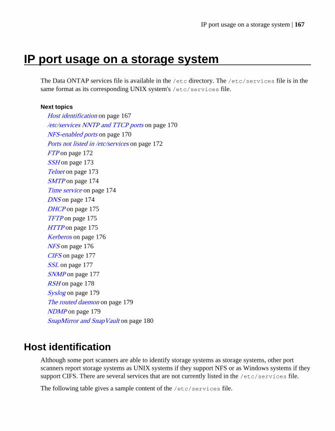
IP port usage on a storage system
The Data ONTAP services file is available in the /etc directory. The /etc/services file is in thesame format as its corresponding UNIX system's /etc/services file.
Next topics
Host identification on page 167
/etc/services NNTP and TTCP ports on page 170
NFS-enabled ports on page 170
Ports not listed in /etc/services on page 172
FTP on page 172
SSH on page 173
Telnet on page 173
SMTP on page 174
Time service on page 174
DNS on page 174
DHCP on page 175
TFTP on page 175
HTTP on page 175
Kerberos on page 176
NFS on page 176
CIFS on page 177
SSL on page 177
SNMP on page 177
RSH on page 178
Syslog on page 179
The routed daemon on page 179
NDMP on page 179
SnapMirror and SnapVault on page 180
Host identificationAlthough some port scanners are able to identify storage systems as storage systems, other portscanners report storage systems as UNIX systems if they support NFS or as Windows systems if theysupport CIFS. There are several services that are not currently listed in the /etc/services file.
The following table gives a sample content of the /etc/services file.
IP port usage on a storage system | 167

Service Port/ Protocol Description
ftp-data 20/tcp # File transfer
protocol
ftp 21/tcp # File transfer
protocol
ssh 22/tcp # SecureAdmin rsh
replacement
telnet 23/tcp # Remote login
(insecure)
smtp 25/tcp # outbound connections
for autosupport
time 37/tcp # Time Service
time 37/udp # Time Service
domain 53/udp # DNS - outbound only
domain 53/tcp # DNS zone transfers -
unused
dhcps 67/udp # DHCP server -
outbound only
dhcp 68/udp # DHCP client - only
first-time setup
tftp 69/udp # Trivial FTP - for
netboot support
http 80/tcp # HTTP license,
FilerView, SecureAdmin
kerberos 88/udp # Kerberos 5 - outbound
only
kerberos 88/tcp # Kerberos 5 - outbound
only
portmap 111/udp # aka rpcbind, used for
NFS
portmap 111/tcp # aka rpcbind, used for
NFS
nntp 119/tcp # unused, shouldn't be
listed here.
168 | Data ONTAP 8.0 7-Mode Network Management Guide

Service Port/ Protocol Description
ntp 123/tcp # Network Time Protocol
ntp 123/udp # Network Time Protocol
netbios-name 137/udp # NetBIOS nameserver -
for CIFS
netbios-dg 138/udp # NetBIOS datagram
service - for CIFS
netbios-ssn 139/tcp # NetBIOS service
session - for CIFS
ssl 443/tcp # Secure FilerView
(SecureAdmin)
cifs-tcp 445/tcp # CIFS over TCP with
NetBIOS framing
snmp 161/udp # For Data Fabric
Manager or other such
tools
ldap 389/tcp # LDAP session
https 443/tcp # SecureAdmin/SSL
shell 514/tcp # rsh, insecure remote
command execution.
syslog 514/udp # outbound only
route 520/udp # for RIP routing
protocol
ldap-ssl 636/tcp # LDAP over SSL
kerberos-sec 750/udp # outbound only, if at
all
kerberos-sec 750/tcp # outbound only, if at
all
nfsd 2049/udp # primary NFS service
nfsd 2049/tcp # primary NFS service
nrv 2050/tcp # Remote Volume
protocol, used in
FlexCache and Restore-
On-Demand
IP port usage on a storage system | 169
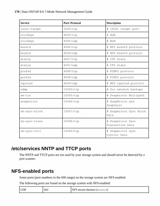
Service Port/ Protocol Description
iscsi-target 3260/tcp # iSCSI target port
nlockmgr 4045/tcp # NLM
nlockmgr 4045/udp # NLM
mountd 4046/tcp # NFS mountd protocol
mountd 4046/udp # NFS mountd protocol
status 4047/tcp # CTP state
status 4047/udp # CTP state
pcnfsd 4048/tcp # PCNFS protocol
pcnfsd 4048/udp # PCNFS protocol
rquotad 4049/udp # NFS rquotad protocol
ndmp 10000/tcp # for network backups
sm-ics 10565/tcp # Snapmirror Multipath
snapmirror 10566/tcp # SnapMirror and
SnapVault
sm-sync-block 10567/tcp # Snapmirror Sync Block
Data
sm-sync-trans 10568/tcp # Snapmirror Sync
Transaction Data
sm-sync-ctrl 10569/tcp # Snapmirror Sync
Control Data
/etc/services NNTP and TTCP portsThe NNTP and TTCP ports are not used by your storage system and should never be detected by aport scanner.
NFS-enabled portsSome ports (port numbers in the 600 range) on the storage system are NFS-enabled.
The following ports are found on the storage system with NFS-enabled:
UDP 602 NFS mount daemon (mountd)
170 | Data ONTAP 8.0 7-Mode Network Management Guide
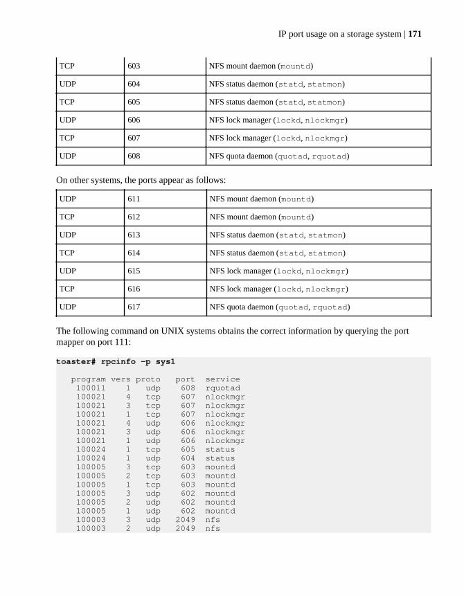
TCP 603 NFS mount daemon (mountd)
UDP 604 NFS status daemon (statd, statmon)
TCP 605 NFS status daemon (statd, statmon)
UDP 606 NFS lock manager (lockd, nlockmgr)
TCP 607 NFS lock manager (lockd, nlockmgr)
UDP 608 NFS quota daemon (quotad, rquotad)
On other systems, the ports appear as follows:
UDP 611 NFS mount daemon (mountd)
TCP 612 NFS mount daemon (mountd)
UDP 613 NFS status daemon (statd, statmon)
TCP 614 NFS status daemon (statd, statmon)
UDP 615 NFS lock manager (lockd, nlockmgr)
TCP 616 NFS lock manager (lockd, nlockmgr)
UDP 617 NFS quota daemon (quotad, rquotad)
The following command on UNIX systems obtains the correct information by querying the portmapper on port 111:
toaster# rpcinfo -p sys1
program vers proto port service 100011 1 udp 608 rquotad 100021 4 tcp 607 nlockmgr 100021 3 tcp 607 nlockmgr 100021 1 tcp 607 nlockmgr 100021 4 udp 606 nlockmgr 100021 3 udp 606 nlockmgr 100021 1 udp 606 nlockmgr 100024 1 tcp 605 status 100024 1 udp 604 status 100005 3 tcp 603 mountd 100005 2 tcp 603 mountd 100005 1 tcp 603 mountd 100005 3 udp 602 mountd 100005 2 udp 602 mountd 100005 1 udp 602 mountd 100003 3 udp 2049 nfs 100003 2 udp 2049 nfs
IP port usage on a storage system | 171
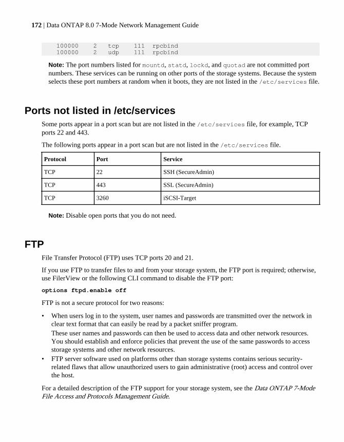
100000 2 tcp 111 rpcbind 100000 2 udp 111 rpcbind
Note: The port numbers listed for mountd, statd, lockd, and quotad are not committed portnumbers. These services can be running on other ports of the storage systems. Because the systemselects these port numbers at random when it boots, they are not listed in the /etc/services file.
Ports not listed in /etc/servicesSome ports appear in a port scan but are not listed in the /etc/services file, for example, TCPports 22 and 443.
The following ports appear in a port scan but are not listed in the /etc/services file.
Protocol Port Service
TCP 22 SSH (SecureAdmin)
TCP 443 SSL (SecureAdmin)
TCP 3260 iSCSI-Target
Note: Disable open ports that you do not need.
FTPFile Transfer Protocol (FTP) uses TCP ports 20 and 21.
If you use FTP to transfer files to and from your storage system, the FTP port is required; otherwise,use FilerView or the following CLI command to disable the FTP port:
options ftpd.enable off
FTP is not a secure protocol for two reasons:
• When users log in to the system, user names and passwords are transmitted over the network inclear text format that can easily be read by a packet sniffer program.These user names and passwords can then be used to access data and other network resources.You should establish and enforce policies that prevent the use of the same passwords to accessstorage systems and other network resources.
• FTP server software used on platforms other than storage systems contains serious security-related flaws that allow unauthorized users to gain administrative (root) access and control overthe host.
For a detailed description of the FTP support for your storage system, see the Data ONTAP 7-ModeFile Access and Protocols Management Guide.
172 | Data ONTAP 8.0 7-Mode Network Management Guide
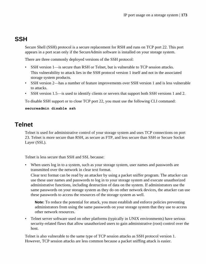
SSHSecure Shell (SSH) protocol is a secure replacement for RSH and runs on TCP port 22. This portappears in a port scan only if the SecureAdmin software is installed on your storage system.
There are three commonly deployed versions of the SSH protocol:
• SSH version 1—is secure than RSH or Telnet, but is vulnerable to TCP session attacks.This vulnerability to attack lies in the SSH protocol version 1 itself and not in the associatedstorage system products.
• SSH version 2—has a number of feature improvements over SSH version 1 and is less vulnerableto attacks.
• SSH version 1.5—is used to identify clients or servers that support both SSH versions 1 and 2.
To disable SSH support or to close TCP port 22, you must use the following CLI command:
secureadmin disable ssh
TelnetTelnet is used for administrative control of your storage system and uses TCP connections on port23. Telnet is more secure than RSH, as secure as FTP, and less secure than SSH or Secure SocketLayer (SSL).
Telnet is less secure than SSH and SSL because:
• When users log in to a system, such as your storage system, user names and passwords aretransmitted over the network in clear text format.Clear text format can be read by an attacker by using a packet sniffer program. The attacker canuse these user names and passwords to log in to your storage system and execute unauthorizedadministrative functions, including destruction of data on the system. If administrators use thesame passwords on your storage system as they do on other network devices, the attacker can usethese passwords to access the resources of the storage system as well.
Note: To reduce the potential for attack, you must establish and enforce policies preventingadministrators from using the same passwords on your storage system that they use to accessother network resources.
• Telnet server software used on other platforms (typically in UNIX environments) have serioussecurity-related flaws that allow unauthorized users to gain administrative (root) control over thehost.
Telnet is also vulnerable to the same type of TCP session attacks as SSH protocol version 1.However, TCP session attacks are less common because a packet sniffing attack is easier.
IP port usage on a storage system | 173
To disable Telnet, you must set options telnet.enable to off.
SMTPSimple Mail Transport Protocol (SMTP) uses TCP port 25. Your storage system does not listen onthis port but makes outgoing connections to mail servers using this protocol when sendingAutoSupport e-mail.
Time serviceYour storage system supports the Network Time Protocol (NTP) for time synchronization.
To synchronize the system time with a network time server, you must ensure that the timed.enableoption is set to on, the timed.proto option is set to ntp, and the timed.servers option is setwith at least one valid time server.
Note: Both controllers in an HA pair should have time synchronization enabled to ensure timeconsistency in the event of controller failover.
For more information about synchronizing the system time, see the Data ONTAP 7-Mode SystemAdministration Guide.
DNSThe Domain Name System (DNS) uses UDP port 53 and TCP port 53. Your storage system does nottypically listen on these ports because it does not run a domain name server. However, if DNS isenabled on your storage system, it makes outgoing connections using UDP port 53 for host name andIP address lookups.
The storage system never uses TCP port 53 because this port is used explicitly for communicationbetween DNS servers. Outgoing DNS queries by your storage system are disabled by turning offDNS support. Turning off DNS support protects against receiving bad information from anotherDNS server.
Because your storage system does not run a domain name server, the name service must be providedby one of the following:
• Network information service (NIS)• An /etc/hosts file• Replacement of host names in the configuration files (such as /etc/exports, /etc/
usermap.cfg, and so on) with IP addresses
DNS must be enabled for participation in an Active Directory domain.
174 | Data ONTAP 8.0 7-Mode Network Management Guide
DHCPClients broadcast messages to the entire network on UDP port 67 and receive responses from theDynamic Host Configuration Protocol (DHCP) server on UDP port 68. The same ports are used forthe BOOTP protocol.
DHCP is used only for the first-time setup of your storage system. Detection of DHCP activity onyour storage system by a port scan other than the activity during the first-time setup indicates aserious configuration or software error.
TFTPTrivial File Transfer Protocol (TFTP) uses TCP port 69. It is used mostly for booting UNIX orUNIX-like systems that do not have a local disk (this process is also known as netbooting) and forstoring and retrieving configuration files for devices such as Cisco routers and switches.
Transfers are not secure on TFTP because it does not require authentication for clients to connect andtransfer files.
Your storage system’s TFTP server is not enabled by default. When TFTP is enabled, theadministrator must specify a directory to be used by TFTP clients, and these clients cannot accessother directories. Even within the TFTP directory, access is read-only. TFTP should be enabled onlyif necessary. You can disable TFTP using the following option:
options tftpd.enable off
You can configure the maximum number of simultaneous connections handled by the TFTP serverby using the tftpd.max_connections option. The default number of TFTP connections is 8. Themaximum number of connections supported is 32.
HTTPHypertext Transport Protocol (HTTP) runs on TCP port 80 and is the protocol used by Web browsersto access Web pages.
Your storage system uses HTTP to access the following:
• Files when HTTP is enabled• FilerView for graphical user interface (GUI) administration• Secure FilerView when SecureAdmin is installed
The SecureAdmin SSL interface accepts connections on TCP port 443. SecureAdmin manages thedetails of the SSL network protocol, encrypts the connection, and then passes this traffic through tothe normal HTTP FilerView interface through a loopback connection. This loopback connection does
IP port usage on a storage system | 175

not use a physical network interface. HTTP communication takes place inside your storage system,and no clear text packets are transmitted.
HTTP is not vulnerable to security attacks because it provides read-only access to documents byunauthenticated clients. Although authentication is not typically used for file access, it is frequentlyused for access to restricted documents or for administration purposes, such as FilerViewadministration. The authentication methods defined by HTTP send credentials, such as user namesand passwords, over the network without encryption. The SecureAdmin product is provided withSSL support to overcome this shortcoming.
Note: In versions earlier than Data ONTAP 7.0, your storage system listens for new connections(by default, set to TCP port 80) even when HTTP is not licensed and FilerView is disabled.However, starting with Data ONTAP 7.0, you can stop your storage system from listening for newconnections by setting the options httpd.enable and httpd.admin.enable to off. If either ofthe options is set to on, your storage system will continue to listen for new connections.
KerberosThere are four Kerberos ports in the /etc/services file: TCP port 88, UDP port 88, TCP port 750,and UDP port 750. These ports are used only for outbound connections from your storage system.Your storage system does not run Kerberos servers or services and does not listen on these ports.
Kerberos is used by your storage system to communicate with the Microsoft Active Directory serversfor both CIFS authentication and, if configured, NFS authentication.
NFSNetwork File System (NFS) is used by UNIX clients for file access. NFS uses port 2049.
NFSv3 and NFSv2 use the portmapper service on TCP or UDP port 111. The portmapper service isconsulted to get the port numbers for services used with NFSv3 or NFSv2 protocols such as mountd,statd, and nlm. NFSv4 does not require the portmapper service.
NFSv4 provides the delegation feature that enables your storage system to grant local file access toclients. To delegate, your storage system sets up a separate connection to the client and sendscallbacks on it. To communicate with the client, your storage system uses one of the reserved ports(port numbers less than 1024). To initiate the connection, the client registers the callback program ona random port and informs the server about it.
With delegations enabled, NFSv4 is not firewall-friendly because several other ports need to beopened up as well.
You can disable the TCP and UDP ports by setting the nfs.tcp.enable and nfs.udp.enableoptions to off.
To disable NFS, you should use the nfs off command.
176 | Data ONTAP 8.0 7-Mode Network Management Guide

CIFSCommon Internet File Service (CIFS) is the successor to the server message block (SMB) protocol.CIFS is the primary protocol used by Windows systems for file sharing.
CIFS uses UDP ports 137 and 138, and TCP ports 139 and 445. Your storage system sends andreceives data on these ports while providing CIFS service. If it is a member of an Active Directorydomain, your storage system must also make outbound connections destined for DNS and Kerberos.
CIFS is required for Windows file service. You can disable CIFS using FilerView or by issuing thecifs terminate command on your storage system console.
Note: If you disable CIFS, be aware that your storage system’s /etc/rc file can be set up toautomatically enable CIFS again after a reboot.
SSLThe Secure Sockets Layer (SSL) protocol provides encryption and authentication of TCPconnections. Data ONTAP supports SSLv2, SSLv3, and Transport Layer Security (TLS) version 1.0.You should use TLSv1.0 or SSLv3 because it offers better security than previous SSL versions.
When SecureAdmin is installed and configured on your storage system, it listens for SSLconnections on TCP port 443. It receives secure Web browser connections on this port and usesunencrypted HTTP, running on TCP port 80, through a loopback connection to pass the traffic toFilerView. This loopback connection is contained within your storage system and no unencrypteddata is transmitted over the network.
You can enable or disable SSL by using FilerView or with the following command:
secureadmin {enable|disable} ssl
For TLS to be used for communication, both the client requesting the connection and the storagesystem must support TLS.
TLS is disabled by default, and setting up SSL does not automatically enable TLS. Before enablingTLS, ensure that SSL has been set up and enabled. To enable or disable TLS, enter the followingcommand:
options tls.enable {on|off}
SNMPSimple Network Management Protocol (SNMP) is an industry-standard protocol used for remotemonitoring and management of network devices over UDP port 161.
SNMP is not secure because of the following reasons:
IP port usage on a storage system | 177

• Instead of using encryption keys or a user name and password pair, SNMP uses a communitystring for authentication. The community string is transmitted in clear text format over thenetwork, making it easy to capture with a packet sniffer.Within the industry, devices are typically configured at the factory to use public as the defaultcommunity string. The public password allows users to make queries and read values but does notallow users to invoke commands or change values. Some devices are configured at the factory touse private as the default community string, allowing users full read-write access.
• Even if you change the read and write community string on a device to something other thanprivate, an attacker can easily learn the new string by using the read-only public communitystring and asking the router for the read-write string.
There are three versions of SNMP:
• SNMPv1 is the original protocol and is not commonly used.• SNMPv2 is identical to SNMPv1 from a network protocol standpoint and is vulnerable to the
same security problems. The only differences between the two versions are in the messages sent,messages received, and types of information. These differences are not important from a securityperspective.
• SNMPv3 is the latest protocol version and includes security improvements but is difficult toimplement and many vendors do not yet support it. SNMPv3 supports several different types ofnetwork encryption and authentication schemes. It allows for multiple users, each with differentpermissions, and solves SNMPv1 security problems while maintaining an important level ofcompatibility with SNMPv2.
SNMP is required if you want to monitor a storage system through an SNMP monitoring tool, suchas DataFabric Manager. The SNMP implementation in the storage system allows read-only access.Regardless of the community string used, the user cannot issue commands or change variables usingSNMP on your storage system.
You should use the snmp.access option to restrict SNMP access to a named set of trusted hosts.
You can disable SNMP entirely by setting the snmp.enable option to off to disable SNMPentirely.
The snmp community delete and snmp community add commands are used to change thecommunity string to something other than the default value.
RSHRemote Shell (RSH) protocol is used for remote command execution. It is less secure than TFTP anduses TCP port 514.
RSH is not secure because passwords are not required for login and commands are easy tomisconfigure. Therefore, you should disable RSH by setting the rsh.enable option to off.
You should use the SSH supplied with SecureAdmin for remote command execution and login. Ifthis is not possible, Telnet is preferred to RSH.
178 | Data ONTAP 8.0 7-Mode Network Management Guide
If RSH is the only alternative, follow these guidelines when using RSH:
• Specify only secure, trusted hosts in the /etc/hosts.equiv file.• Always use IP addresses rather than host names in the /etc/hosts.equiv file.• Always specify a single IP address with a single user name on each line in /etc/hosts.equiv
file.• Use the rsh.access option instead of the trusted.hosts option for access control.• Make sure the ip.match_any_ifaddr option is set to off.
SyslogYour storage system sends messages to hosts specified by the user in the /etc/syslog.conf fileby using the syslog protocol on UDP port 514. It does not listen on this port, nor does it act as asyslog server.
The routed daemonThe routed daemon, routed, listens on UDP port 520. It receives broadcast messages from routers orother hosts using Routing Information Protocol (RIP). These messages are used by your storagesystem to update its internal routing tables to determine which network interfaces are optimal foreach destination.
Your storage system never broadcasts RIP messages containing routes because Data ONTAP is notcapable of acting as a router.
RIP is not secure because an attacker can easily send artificial RIP messages and cause hosts runningthe routed daemon (such as your storage system) to redirect network traffic to the attacker. Theattacker can then receive and shift this traffic for passwords and other information and send it on tothe actual destination, where the intrusion is undetected. This method can also be used as a startingpoint for TCP session attacks.
Because of these security issues, use static routes (those set up using the route command on yourstorage system) instead of using the routed daemon.
NDMPNetwork Data Management Protocol (NDMP) runs on TCP port 10000 and is used primarily forbackup of network-attached storage (NAS) devices, such as storage systems.
The protocol defines three authentication methods:
• NONE—allows authentication without restriction• TEXT—sends a clear text password over the network, similar to Telnet or FTP
IP port usage on a storage system | 179

• MD5—uses the MD5 message digest algorithm along with a challenge-response messageexchange to implement a secure login mechanism
Your storage system supports both the TEXT and MD5 authentication methods. Most NDMP-enabled backup software uses MD5 by default.
To entirely disable the TEXT authentication method, you should set the ndmpd.authtype option tochallenge.
To restrict NDMP commands to certain authorized backup hosts, you should use the ndmp.accessoption.
Regardless of the authentication method used, NDMP sends backup data in decrypted format overthe network, as does most other backup software. A separate network optimized for backup is acommon means to increase performance while retaining data security.
To disable NDMP, you should set the ndmp.enable option to off.
SnapMirror and SnapVaultSnapMirror and SnapVault use TCP port 10566 for data transfer. Network connections are alwaysinitiated by the destination system; that is, SnapMirror and SnapVault pull data rather than push data.
Authentication is minimal with both SnapMirror and SnapVault. To restrict inbound TCPconnections on port 10566 to a list of authorized hosts or IP addresses, you should configure thesnapmirror.access or snapvault.access option. When a connection is established, thedestination storage system communicates its host name to the source storage system, which then usesthis host name to determine if a transfer is allowed. You should confirm a match between the hostname and its IP address. To confirm that the host name and the IP address match, you should set thesnapmirror.checkip.enable option to on.
To disable SnapMirror, you should set the snapmirror.enable option to off. To disableSnapVault, you should set the snapvault.enable option to off.
180 | Data ONTAP 8.0 7-Mode Network Management Guide

Error codes for the netdiag command
Network error codes are generated by the netdiag command. They describe the network problemsand suggest the actions that you can take.
The following table lists some network error codes, describes the problems that the error codes pointto, and suggests actions that you can take to fix the problems.
Note: Only a small fraction of the possible network error messages are presented in the followingtable. If you receive any problem code not listed in this table, contact your technical support.
Error code Description Recommended actions
201 Link not detected. Complete the following steps until you detect a link:
1. Ensure that the cable is connected between the switch port andyour storage system interface, and that both ends are securelyattached.
2. Ensure that the switch port and interface are both configured tothe up status, and one of the following is true:
• Autonegotiation is enabled on both sides
• Autonegotiation is disabled on both sides, and the duplexand speed settings match
3. Because the switch port, cable, or NIC might be faulty, replacethem, one by one, to locate the fault.
4. If the problem persists, contact your technical support.
203 No link is detectedbecause of a speedmismatch.
Change the interface configuration or peer switch portconfiguration to match the speed.
204 The interface is notconfigured to the up
status.
Configure the interface state to the up status.
205 Duplex mismatch. Change the interface or peer switch port duplex setting so that theymatch.
206 Link capacity problem. Upgrade to a faster interface.
Error codes for the netdiag command | 181

Error code Description Recommended actions
207 The interface is nottransmitting orreceiving.
Complete the following steps:
1. Pull the network cable out from the network interface card.
2. Reinsert the cable.
3. Use ifstat to display statistics.
• Link errors, such as CRC, are caused by a faulty switchport, cable, or NIC; replace them one by one to locate thefault.
• Out-of-resource errors are caused by heavy loads.
4. If the problem persists, contact your technical support.
208 Excessive I/O errors. Complete the following steps:
1. Reset the interface card.
2. Check the cables.
3. If the problem persists, contact your technical support.
209 Excessive unsupportedprotocol packets arebeing sent to yourstorage system.
The problem is not with your storage system.
Contact your network administrator to resolve the problem.
301 The IP address and thenetmask areinconsistent with theassigned broadcastaddress.
Change the configuration by using the ifconfig command.
302 The broadcast addressreaches a larger set ofhosts than the standardbroadcast computedfrom the IP address andnetmask.
If this behavior is erroneous, change the configuration.
303 There are excessive IPreassembly errors.
Switch from NFS over UDP to NFS over TCP.
401 The TCP windowadvertised by the clientis too small.
The problem is not with your storage system.
Reconfigure the client.
182 | Data ONTAP 8.0 7-Mode Network Management Guide

Error code Description Recommended actions
402 There is excessivepacket loss on thesending side.
The problem is not with your storage system.
Examine the network and the client for congestion.
403 There is excessivepacket loss on thereceiving side.
The problem is not with your storage system.
Examine the network and the client for congestion.
404 The average TCPpacket size is poor onthe receiving sidebecause the network,client, or both are notenabled to supportjumbo frames.
The problem is not with your storage system.
Enable support for jumbo frames in network devices and theclient.
405 The average TCPpacket size is poor onthe receiving sidebecause of a problemwith the network, client,or both.
The problem is not with your storage system.
Examine the network and client for configured MTUs.
406 The average TCPpacket size is poor onthe receiving sidebecause of a clientapplication problem.
The problem is not with your storage system.
Examine the client application data transmission strategy.
407 Excessive TCP listensocket drops becausethe system isoverloaded or undersecurity attack.
Contact your network administrator to resolve the problem.
408 There are excessivefiltered TCP port dropsbecause the system isunder security attack.
Check your network.
Contact your network administrator to resolve the problem.
Error codes for the netdiag command | 183

Error code Description Recommended actions
409 There are excessiveembryonic TCPconnection dropsbecause the system isunder security attack orbecause a client has abug.
A packet trace might assist in locating the problem. Contact yournetwork administrator to resolve the problem.
410 Excessive TCPchecksum errors. Theseerrors can be caused bybad hardware on theclient, in the networkinfrastructure (forexample, blade inswitch or router), or onthe NIC. These errorscan also be caused by abug in the client.
• Check your client system for bugs.
• Replace hardware components until the problem is resolved.
• Contact your network administrator to resolve the problem.
411 There are packetsbecause of a client.Your system might beunder a security attack.
The problem is not with your storage system.
• Check your client system for bugs.
• Check for a security attack.
451 There are excessiveUDP checksum errors.
Switch from NFS over UDP to NFS over TCP.
601 The DNS server is notreachable.
Examine the DNS server and the path to the DNS server.
602 The NIS server is notreachable.
Examine the NIS server and the path to the NIS server.
184 | Data ONTAP 8.0 7-Mode Network Management Guide

Index/etc/gateways file 53/etc/hosts file 61–63, 72
about 61adding, host name 62changing host name 63creating, from NIS master 72editing, with FilerView 63hard limits 63host-name resolution 61
/etc/nsswitch.conf file 61, 79, 80/etc/resolv.conf file 65, 66, 68/etc/resolv.conf file, hard limits 65/etc/services file 167, 172/etc/syslog.conf file 179
10 Gigabit Ethernet controller 159, 161LINK INFO statistics 159, 161RECEIVE statistics 159, 161statistics 159, 161TRANSMIT statistics 159, 161
10 Gigabit Ethernet interface 153–155statistics 153–155
A
A record 66ACP 28–30
defined 28enabling 29subnet, about 30
alias address 41creating 41deleting 41
Alternate Control Path (ACP) 28defined 28
B
Baseboard Management Controller (BMC) 25blocking protocols 43BMC 26
how to configure 26managing with Data ONTAP commands 26
C
CDP 121–123, 125configuring hold time 122configuring periodicity 123Data ONTAP support 121disabling 122enabling 122online migration 121viewing neighbor information 125viewing statistics 123
CDP (Cisco Discovery Protocol) 121CIFS (Common Internet File Service) 177Cisco Discovery Protocol (CDP) 121commands 23, 33, 34, 37, 41, 42, 44, 46, 52, 54, 56–59,
66, 76, 77, 86, 88–92, 101–105, 107–113, 127,130–132, 134–137, 139, 145–147, 153–155,181
dns flush 66dns info 66ifconfig 33, 34, 37, 41, 42, 54, 88ifconfig -a 44ifgrp add 108ifgrp create 101ifgrp create lacp 107ifgrp create multi 105ifgrp create single 102ifgrp delete 109ifgrp destroy 113ifgrp favor 103ifgrp nofavor 104ifgrp stat 112ifgrp status 110, 111ifstat 37, 44, 46, 153–155netdiag 145, 181netdiag -s 146netstat 44netstat -p icmp 147netstat -rn 57, 58nis info 76, 77ping 145pktt 145route 52, 54, 59route -s 57route add 54routed 56
Index | 185

routed status 58snmp 131, 132snmp authtrap 132snmp community 132snmp contact 132snmp init 132snmp location 132snmp traphost 132snmp traps 127, 132, 136, 137, 139snmp traps load 137snmpbulkget 134, 135snmpbulkwalk 134, 135snmpwalk 130, 134, 135sysconfig 23useradmin group add 130useradmin role add 130useradmin user add 130vlan add 86, 89vlan create 86vlan delete 86, 90vlan modify 86, 91vlan stat 86, 92
Common Internet File Service (CIFS) 177
D
default route 54, 57, 58DHCP 175diagnose network problems 145diagnostic tests 145, 146DNS 61, 64–70, 78, 174
about 64configuration information 66configuring, from the command-line interface 65configuring, with FilerView 78disabling 65disabling, dynamic updates 69dynamic updates 67, 68enabling 65enabling, dynamic updates 69fully qualified domain names (FQDN) 66host-name resolution 61, 64, 66lookup 66modifying dns.update.ttl 70name cache 66port used 174time-to-live (TTL) 68
Domain Name System (DNS) 64DS4243 28
ACP protocol 28
Dual 10G Ethernet controller 162–164LINK INFO statistics 162–164RECEIVE statistics 162–164statistics 162–164TRANSMIT statistics 162–164
duplex settings, correcting mismatches 165dynamic DNS 67–69
about 67, 68disabling 69disabling, for an IP address 69enabling 69in Data ONTAP 68
Dynamic Host Configuration Protocol (DHCP) 64, 175
E
e0M 24error messages 181
error code, netdiag 181networking 181
Ethernet frame 32jumbo frame 32
F
fast path 51, 52, 55about 51, 52disabling 55enabling 55with asymmetric routing 51, 52with NFS-over-UDP 51, 52with ping utility 51, 52with TCP 51, 52with Telnet 51, 52
File Transfer Protocol (FTP) 172FilerView 42, 49, 56, 59, 78, 79, 132, 137
changing host-name search order 79configuring DNS 78configuring NIS 78configuring SNMP 132network interface settings 42network report 49routed daemon 56SNMP traps 137viewing routing table 59viewing, network interface statistics 49
flow control 32, 37about 32, 37options 37
frame 31, 32
186 | Data ONTAP 8.0 7-Mode Network Management Guide

about 31characteristics 31Ethernet 31flow 32frame size 31jumbo 31jumbo frame 31MTU size 31Pause Off 32Pause On 32
FTP 172fully qualified domain names (FQDN) 66
GGARP (Generic Attribute Registration Protocol) 83GARP VLAN Registration Protocol (GVRP) 83Generic Attribute Registration Protocol (GARP) 83Gigabit Ethernet controller 149, 151, 152
LINK INFO statistics 149, 151, 152RECEIVE statistics 149, 151, 152statistics 149, 151, 152TRANSMIT statistics 149, 151, 152
Gigabit Ethernet interface 153–158interface statistics 153–155statistics 156–158
GVRP 85GVRP (GARP VLAN Registration Protocol) 83
Hhost 21, 22, 167
identification 167naming 21, 22
host name 21, 22, 61–64, 70, 73, 79, 80about 21, 22adding, in /etc/hosts file 62changing 63changing search order 79, 80resolution 79resolution, with /etc/hosts file 61resolution, with DNS 64resolution, with NIS 70, 73search order 79
host-name resolution 61, 64, 66, 70, 73, 79, 80about 61, 80FilerView 79using /etc/hosts file 61using DNS 64, 66using NIS 70, 73
HTTP 175
Hypertext Transport Protocol (HTTP) 175
I
ICMP 147, 148ICMP redirect messages 148ICMP Router Discovery Protocol (IRDP) 53IEEE 802.1Q standards 85ifgrp 102, 109, 112, 113
creating single-mode 102deleting interfaces 109destroying 113viewing statistics 112
inter-switch link (ISL) 114interface group 21, 22, 95–98, 100, 101, 103–105, 107,
108, 110, 111, 113–117about 95adding interfaces 108dynamic multimode 96, 98, 107dynamic multimode, LACP log 107failover, second-level 115in an HA pair 116LACP 107load balancing 100load balancing, IP address based 100load balancing, MAC address based 100manage 101naming 21, 22second-level 113, 114, 116, 117selecting preferred interface 103single-mode 96, 97specifying nonfavored interface 104static multimode 96, 97, 105status 111types 96viewing status 110
interface groups 105single-mode, failure scenarios 105
IP address 33–38, 40, 41alias 41broadcast 35configuration 33configuring 34flow control 37media type 36MTU size 36partner IP, specifying 38removing 40subnet mask 35
IP ports 167
Index | 187

J
jumbo frames 31, 32advantages 31, 32configuring 32network requirements 32size 31
K
Kerberos 176
L
LACP (Link Aggregation Control Protocol) 98LACP log file 107Link Aggregation Control Protocol (LACP) 98LINK INFO statistics 153–158
10 Gigabit Ethernet interface 153–155Gigabit Ethernet interface 153–158
load balancing 100IP address based 100MAC address based 100multimode interface groups 100round-robin 100
localhost 61
M
MIB 128/etc/mib/iscsi.mib 128/etc/mib/netapp.mib 128custom mib 128iSCSI MIB 128
multimode interface groups 100load balancing, IP address based 100load balancing, MAC address based 100load balancing, port-based 100load balancing, round-robin 100
N
NDMP (Network Data Management Protocol) 179negotiated failover 39network connectivity 121
discovering 121Network Data Management Protocol (NDMP) 179Network File System (NFS) 176Network Information Service (NIS) 70
network interface 21–23, 33, 37, 39, 41–44, 46, 49, 149,153–155
10 Gigabit Ethernet 2110/100/1000 Ethernet 21automatic takeover 39blocking protocols 43changing status 42clearing statistics 46configuration 33configuring 33down, status 42flow control 37Gigabit Ethernet 21maximum number 23modifying with FilerView 42naming 21, 22nfo 39statistics 149statistics for T204E 153–155statistics for T204V 153–155statistics for T210 153–155statistics for T320 153–155trusted 37types 21unblocking protocols 43untrusted 37up, status 42viewing context statistics 44viewing settings 41viewing statistics 46viewing statistics, FilerView 49
network interfaces 44viewing statistics 44
Network Time Protocol (NTP) 174NFS 176
port used 176NIC 26
CPU efficiency 26LSO 26TSO 26
NIS 61, 70–78about 70administrative commands 71, 73
ypcat 73ypgroup 73ypmatch 73yppush 71ypwhich 73
configure 73configuring, with FilerView 78
188 | Data ONTAP 8.0 7-Mode Network Management Guide

creating /etc/hosts file 72disabling 74enabling 74enabling slave 75host-name resolution 61, 70, 73hosts map 70, 71master 71, 72netgroup cache 76selecting the master server 71slave 71, 72specifying domain name 74specifying servers 75statistics 76viewing information 76viewing, performance statistics 77
NIS (Network Information Service) 70NIS slave 71, 72, 75
about 71enabling 75guidelines 72improve performance 71
NNTP 170NTP 174
O
OID 128options 54, 55, 66, 69–72, 74, 75, 130, 131, 146–148
dns.cache.enable 66dns.update.enable 69dns.update.ttl 70ip.fastpath.enable 55ip.icmp_ignore_redirect.enable 54, 148ip.ping_throttle.drop_level 146, 147nis.domainname 74nis.enable 74nis.server 72nis.servers 71, 75nis.slave.enable 75snmp.access 131snmp.enable 130
P
pause frame 32performance, storage system 165ping 145–147
command 145diagnose problems 146throttling 146
throttling, disabling 147throttling, threshold status 147throttling, threshold value 147
port 176, 179, 180for SnapMirror 180for SnapVault 180NDMP 179NFS 176
port usage 167ports 170
TCP 170UDP 170
ports, IP 167ports, NFS-enabled 170
RRECEIVE statistics 153–158
10 Gigabit Ethernet interface 153–155Gigabit Ethernet interface 153–158
Remote LAN Module (RLM) 25Remote Shell (RSH) 178reverse lookup 66RLM 25
how to configure 25managing with Data ONTAP commands 25
route 54default 54
route metric 58routed daemon 53, 55, 56, 179
about 53disable 55enable 55port usage 179turning off 53, 56turning off, with FilerView 56turning on 56turning on, with FilerView 56
routing 51–59about 51default route 54, 57, 58fast path 51, 52, 55FilerView 56managing routing table 52methods 51modifying routing table 59routed daemon 53, 55, 56routing table 54, 57vFiler units 54viewing with FilerView 59
routing information 58, 59
Index | 189

Routing Information Protocol (RIP) 53, 179routing protocols 58, 59routing table 52, 54, 57–59
commands to manage 52flags 58modify, circumstances 54modifying 59vFiler units 54viewing 57viewing with FilerView 59
RSH 178
S
second-level interface group 114guidelines for creating 114
Secure Shell (SSH) 173Secure Sockets Layer (SSL) 177services file 167Simple Mail Transport Protocol (SMTP) 174Simple Network Management Protocol (SNMP) 127,
177SMTP 174SNMP 127, 128, 130–143, 177
about 127access privileges, setting 131agent 127, 128agent, configure 128authKey security 133authNoPriv security 133authProtocol security 133commands 132, 134, 135configuring group, v3 130configuring role, v3 130configuring users, v3 130configuring, with FilerView 132disabling 130enabling 130examples 134, 135login-snmp capability, v3 130MIBs 127, 128modifying configuration 131modifying, with FilerView 132noAuthNoPriv security 133port usage 177restricting access 131security parameters 133traps 128traps, configuration file 137traps, define 136
traps, examples 138traps, guidelines for creating 136traps, modify 136traps, modifying 137traps, modifying with FilerView 137traps, parameter 142traps, parameters 139–143traps, types 127traps, user-defined 135traps, viewing 137traps, viewing with FilerView 137version 3 (SNMPv3) 127viewing configuration 131
SNMP (Simple Network Management Protocol) 127SNMP traps 127, 135–143
backoff-calculator parameter 142backoff-multiplier parameter 143backoff-step parameter 142built-in 127commands 139configuring, in a file 137creating 136defining 137edge-1 parameter 141edge-1-direction parameter 141edge-2 parameter 141edge-2-direction parameter 141example 138guidelines 136interval parameter 141interval-offset parameter 142loading 137message parameter 143modifying 136, 137modifying, with FilerView 137parameters 139priority parameter 143rate-interval parameter 142trigger parameter 140user-defined 127, 135var parameter 140viewing 137viewing, with FilerView 137
SNMPv3 127, 130, 134, 135about 127configuring group 130configuring role 130configuring users 130example 134, 135login-snmp capability 130
190 | Data ONTAP 8.0 7-Mode Network Management Guide

split-network condition 114SSH 173SSL 177statistics 156–158
Gigabit Ethernet interface 156–158syslog 179
T
TCP Segmentation Offload (TSO) 27Telnet 173TFTP 175time service 174time-to-live (TTL) 68, 70TLS 177TRANSMIT statistics 153–158
10 Gigabit Ethernet interface 153–155Gigabit Ethernet interface 153–158
Transport Layer Security version (TLS) 177transport layer, diagnosing 145Trivial File Transfer Protocol (TFTP) 175TSO 27
Data ONTAP support 27viewing statistics 27
TSO (TCP Segmentation Offload) 27TTCP 170
U
unblocking protocols 43
V
VLAN 21, 22, 81–86, 88–92about 81adding an interface 89advantages 84commands 86configuring 85, 88configuring GVRP 83creating 86deleting 90GVRP 83membership 81, 82modifying 91naming 21, 22prerequisites 85tagged traffic 89tags 83untagged traffic 89viewing statistics 92
Index | 191