Embed Size (px)
Citation preview

Data Communications
Multiplexing

Multiplexing

Frequency Division MultiplexingFDMUseful bandwidth of medium exceeds
required bandwidth of channelEach signal is modulated to a different
carrier frequencyCarrier frequencies separated so signals do
not overlap (guard bands)e.g. broadcast radioChannel allocated even if no data

Frequency Division MultiplexingDiagram

FDM System

FDM of Three Voiceband Signals

Analog Carrier SystemsAT&T (USA)Hierarchy of FDM schemesGroup
12 voice channels (4kHz each) = 48kHzRange 60kHz to 108kHz
Supergroup60 channelFDM of 5 group signals on carriers between 420kHz
and 612 kHz
Mastergroup10 supergroups
Synchronous Time Division MultiplexingData rate of medium exceeds data rate of
digital signal to be transmittedMultiple digital signals interleaved in timeMay be at bit level of blocksTime slots preassigned to sources and fixedTime slots allocated even if no dataTime slots do not have to be evenly
distributed amongst sources

Time Division Multiplexing

TDM System
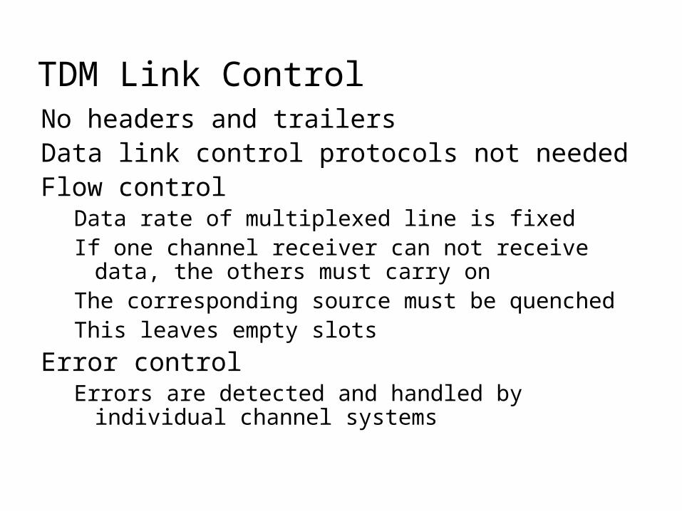
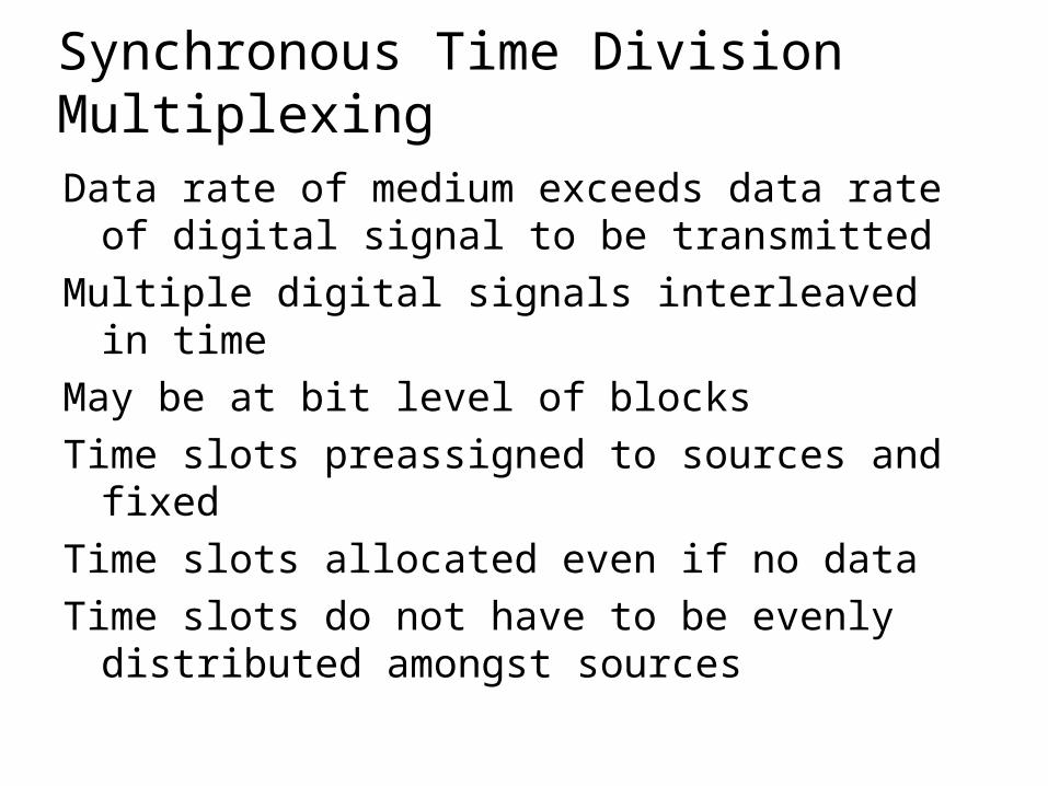
TDM Link ControlNo headers and trailersData link control protocols not neededFlow control
Data rate of multiplexed line is fixedIf one channel receiver can not receive data, the
others must carry onThe corresponding source must be quenchedThis leaves empty slots
Error controlErrors are detected and handled by individual
channel systems

Data Link Control on TDM

FramingNo flag or SYNC characters bracketing TDM
framesMust provide synchronizing mechanismAdded digit framing
One control bit added to each TDM frameLooks like another channel - “control channel”
Identifiable bit pattern used on control channele.g. alternating 01010101…unlikely on a data
channelCan compare incoming bit patterns on each
channel with sync pattern

Pulse StuffingProblem - Synchronizing data sourcesClocks in different sources driftingData rates from different sources not related
by simple rational numberSolution - Pulse Stuffing
Outgoing data rate (excluding framing bits) higher than sum of incoming rates
Stuff extra dummy bits or pulses into each incoming signal until it matches local clock
Stuffed pulses inserted at fixed locations in frame and removed at demultiplexer

TDM of Analog and Digital Sources

Digital Carrier SystemsHierarchy of TDMUSA/Canada/Japan use one systemITU-T use a similar (but different) systemUS system based on DS-1 formatMultiplexes 24 channelsEach frame has 8 bits per channel plus one
framing bit193 bits per frame

Data Communications and Computer Networks Chapter 5
The T-1 multiplexor stream is a continuous series of frames.

Digital Carrier Systems (2)For voice each channel contains one word of
digitized data (PCM, 8000 samples per sec)Data rate 8000x193 = 1.544MbpsFive out of six frames have 8 bit PCM samplesSixth frame is 7 bit PCM word plus signaling bitSignaling bits form stream for each channel
containing control and routing info
Same format for digital data23 channels of data
7 bits per frame plus indicator bit for data or systems control
24th channel is sync

Mixed DataDS-1 can carry mixed voice and data signals24 channels usedNo sync byteCan also interleave DS-1 channels
Ds-2 is four DS-1 giving 6.312Mbps

ISDN User Network InterfaceISDN allows multiplexing of devices over
single ISDN lineTwo interfaces
Basic ISDN InterfacePrimary ISDN Interface

Basic ISDN Interface (1)Digital data exchanged between subscriber and
NTE - Full DuplexSeparate physical line for each directionPseudoternary coding scheme
1=no voltage, 0=positive or negative 750mV +/-10%
Data rate 192kbpsBasic access is two 64kbps B channels and one
16kbps D channelThis gives 144kbps multiplexed over 192kbpsRemaining capacity used for framing and sync

Basic ISDN Interface (2)B channel is basic user channelDataPCM voiceSeparate logical 64kbps connections o
different destinationsD channel used for control or data
LAPD frames
Each frame 48 bits longOne frame every 250s

Frame Structure

Sonet/SDHSynchronous Optical Network (ANSI)Synchronous Digital Hierarchy (ITU-T)CompatibleSignal Hierarchy
Synchronous Transport Signal level 1 (STS-1) or Optical Carrier level 1 (OC-1)
51.84MbpsCarry DS-3 or group of lower rate signals (DS1
DS1C DS2) plus ITU-T rates (e.g. 2.048Mbps)Multiple STS-1 combined into STS-N signalITU-T lowest rate is 155.52Mbps (STM-1)

SONET Frame Format

SONET STS-1 Overhead Octets

Statistical TDMIn Synchronous TDM many slots are wastedStatistical TDM allocates time slots
dynamically based on demandMultiplexer scans input lines and collects
data until frame fullData rate on line lower than aggregate rates
of input lines

Statistical TDM Frame Formats

PerformanceOutput data rate less than aggregate input
ratesMay cause problems during peak periods
Buffer inputsKeep buffer size to minimum to reduce delay

Buffer Size and Delay

Asymmetrical Digital Subscriber LineADSLLink between subscriber and network
Local loop
Uses currently installed twisted pair cableCan carry broader spectrum1 MHz or more

ADSL DesignAsymmetric
Greater capacity downstream than upstream
Frequency division multiplexingLowest 25kHz for voice
Plain old telephone service (POTS)
Use echo cancellation or FDM to give two bandsUse FDM within bands
Range 5.5km

ADSL Channel Configuration

Discrete MultitoneDMTMultiple carrier signals at different frequenciesSome bits on each channel4kHz subchannelsSend test signal and use subchannels with
better signal to noise ratio256 downstream subchannels at 4kHz (60kbps)
15.36MHzImpairments bring this down to 1.5Mbps to 9Mbps

DMT Transmitter

Wavelength Division MultiplexingWavelength division multiplexing multiplexes multiple data streams onto a single fiber optic line.
Different wavelength lasers (called lambdas) transmit the multiple signals.
Each signal carried on the fiber can be transmitted at a different rate from the other signals.
Dense WDM – High number of lambdas
Coarse WDM – A few lambdas

Code Division MultiplexingAlso known as code division multiple access
An advanced technique that allows multiple devices to transmit on the same frequencies at the same time.
Each mobile device is assigned a unique 64-bit code
To send a binary 1, mobile device transmits the unique code
To send a binary 0, mobile device transmits the inverse of code

Code Division MultiplexingReceiver gets summed signal, multiplies it by receiver code, adds up the resulting values
Interprets as a binary 1 if sum is near +64
Interprets as a binary 0 if sum is near –64

Code Division Multiplexing ExampleFor simplicity, assume 8-chip spreading codes
3 different mobiles use the following codes:
-Mobile A: 10111001
-Mobile B: 01101110
-Mobile C: 11001101
Assume Mobile A sends a 1, B sends a 0, and C sends a 1

Code Division Multiplexing ExampleSignal code: 1-chip = +N volt; 0-chip = -N volt
Three signals transmitted:
-Mobile A sends a 1, or 10111001, or +-+++--+
-Mobile B sends a 0, or 10010001, or +--+---+
-Mobile C sends a 1, or 11001101, or ++--++-+
Summed signal received by base station: +3, -1, -1, +1, +1, -1, -3, +3

Code Division Multiplexing ExampleBase station decode for Mobile A:
Signal received: +3,-1,-1,+1,+1,-1,-3,+3
Mobile A’s code: +1,-1,+1,+1,+1,-1,-1,+1
Product result: +3,+1,-1,+1,+1,+1,+3,+3
Sum of Product results: +12
Decode rule: For result near +8, data is binary 1

Code Division Multiplexing ExampleBase station decode for Mobile B:
Signal received: +3,-1,-1,+1,+1,-1,-3,+3
Mobile B’s code: -1,+1,+1,-1,+1,+1,+1,-1
Product result: -3,-1,-1,-1,+1,-1,-3,-3
Sum of Product results: -12
Decode rule: For result near -8, data is binary 0

Optical Spatial Division MultiplexingImproves network utilization of SONET networks
Fact – data traffic is often bursty
Fact – SONET is sync TDM
Sync TDM does not like bursty traffic
OSDM is not limited to multiples of 1.544 Mbps containers

Orthogonal Frequency Division MultiplexingOFDM is a discrete multi-tone technology
Numerous signals of different frequencies are combined to form a single signal for transmission
Before combining, each carrier is phase modulated to represent bits
HomePlug technology modulates data bits on 84 individual carriers ranging from 4 MHz – 21 MHz

Business Multiplexing In ActionXYZ Corporation has two buildings separated by a distance of 300 meters.
A 3-inch diameter tunnel extends underground between the two buildings.
Building A has a mainframe computer and Building B has 66 terminals.
List some efficient techniques to link the two buildings.

Data Communications and Computer Networks Chapter 5

Possible SolutionsConnect each terminal to the mainframe computer using separate point-to-point lines.
Connect all the terminals to the mainframe computer using one multipoint line.
Connect all the terminal outputs and use microwave transmissions to send the data to the mainframe.
Collect all the terminal outputs using multiplexing and send the data to the mainframe computer using a conducted line.

Review Questions1. What is FDM used for? What are its
advantages? Disadvantages?2. If you FDM 20 channels together, each
channel 40,000 Hz, what is total bandwidth?
3. What is TDM used for? What are its advantages? Disadvantages?
4. If you sync TDM 40 voice channels together, what is the total data rate?
5. What is the advantage of stat TDM? Any disadvantages?

Review Questions6. In a T-1, how many frames are
transmitted per second? How many channels within one frame? What is the sync bit used for?
7. In ISDN, how many channels are transmitted on a basic rate service? What is the data rate of each of those channels? What is the D channel used for?