Embed Size (px)
Citation preview

Data Communications:Conversion, Modulation and Multiplexing
Chapter 5
The Management of Telecommunications, 2nd edition
Houston H. Carr and Charles A. Snyder

2Chapter 5
Introduction
Until the early 1990s, voice and fax were served by one network, data by another, television by another. By moving all of these to a digital mode, there is the potential to serve them all with a single transport capability: a single network.

3Chapter 5
Analog voice
The public switched telephone network is an analog network developed to handle voice traffic.
Amplifiers are placed every mile or so to compensate for loss of signal strength due to attenuation.
Boosting analog signals through repeaters amplifies all parts of the signal, including noise.

4Chapter 5
Digital voice
A method of avoiding problems caused by amplifying an analog signal is to convert the analog voice signal to a digital form for transmission.
Digital signals also attenuate over distance, however digital signals are regenerated and amplified instead of just being amplified when required, leaving the noise behind.

5Chapter 5
Digital voice Transmitting voice as data
communications instead of an analog signals provides a cleaner signal at the destination.
Digital voice can be handled the same way as data, with the exception that reception delays are less tolerated for voice than data.
6Chapter 5
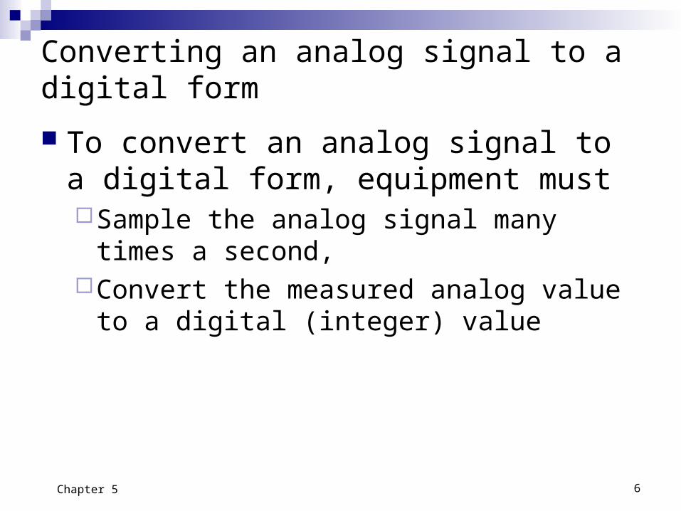
Converting an analog signal to a digital form
To convert an analog signal to a digital form, equipment must Sample the analog signal many times a
second,Convert the measured analog value to a
digital (integer) value

7Chapter 5
Digital Signal Regeneration
From dataprocessingmachine
0 1 0 0 01 1
0 1 0 0 01 1 0 1 0 0 01 1
Regenerativerepeater

8Chapter 5
Sine wave
A sine wave represents a simple analog signal, much like a voice conversation.
Modulating sine-wave signal

9Chapter 5
Converting an Analog Signal to Digital
A device samples the signal strength at each signal, a through n, and measures the values of 1 through 5 volts (analog)
5
6
4
3
2
1
a nklmjghifedcb
a = 1 = 0001
e = 5 = 0101
d = 4 = 0100
c = 3 = 0011
b = 2 = 0010
f = 5 = 0101
g = 4 = 0100o
ooo
o
o
oo
o
o
o
o
o
o

10Chapter 5
Converting analog
signals to digital The analog values
are represented as binary numbers and transmitted over a network as digital data.
Decimal Binary
0 0 0000
1 0 0001
2 0 0010
3 0 0011
4 0 0100
5 0 0101
6 0 0110
7 0 0111
8 0 1000
9 0 1001
10 0 1010
11 0 1011
12 0 1100
13 0 1101
14 0 1110
15 0 1111

11Chapter 5
Converting analog signals to digital The equipment at the receiving end of the
digital circuit converts the binary numbers back to analog signals, voltage levels, using the same timing as the original sampling device.

12Chapter 5
Converting analog signals to digital The fidelity of reproducing the analog signal is
dependent on the sample rate and the number of integer sample points.
A rate of 8,000 times per second is required for a good representation of telephone conversation. This is based on Bell Labs research; the sampling rate is two times the highest frequency.
The system requires 256 integer values of measurement.
13Chapter 5
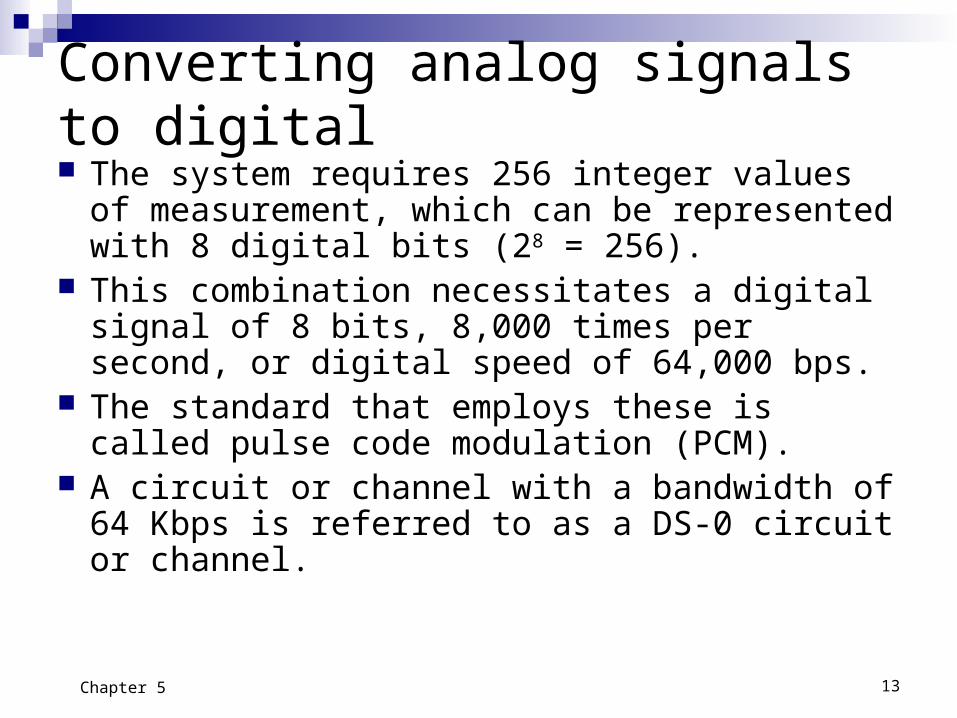
Converting analog signals to digital The system requires 256 integer values of
measurement, which can be represented with 8 digital bits (28 = 256).
This combination necessitates a digital signal of 8 bits, 8,000 times per second, or digital speed of 64,000 bps.
The standard that employs these is called pulse code modulation (PCM).
A circuit or channel with a bandwidth of 64 Kbps is referred to as a DS-0 circuit or channel.

14Chapter 5
Pulse code modulation Pulse Code Modulation (PCM)
samples the level of a voice conversation 8,000 times per second using a scale of 256 integer points,
converts each integer measurement into an 8-bit code, and
Transmits the resultant information at a speed of 64,000 bps.
The receiving unit reverses the process.

15Chapter 5
Adaptive Differential Pulse Code Modulation
Adaptive Differential Pulse Code Modulation (ADPCM) technology measures the signal like PCM, but transmits the difference between successive
measured values instead of the value itself. Allows the use of a 4-bit code to represent the
difference value and reduces the signal requirement to 32,000 bps.
The system uses 3 bits to represent 8 integer values and 1 bit to note whether the change was positive or negative.

16Chapter 5
PCM and ADPCM
Off-the-shelf components can provide PCM (64 Kbps), ADPCM (32 Kbps), and 16 Kbps Digital-to-Analog and Analog-to-Digital conversion without loss of sound quality

17Chapter 5
Channels
TVstation
TV receiver
Channel
Channels are logical paths for communicating data
It is not necessarily a pair of wires. A channel connects the source to
the receiver or destination Thought of as a one-way
communications path. Transmission is usually electrical,
but can also be photonic

18Chapter 5
Circuits A circuit is a means of
connecting two points for communication
Circuits are physical connections and can be divided into channels
A two-way communications path.
Terminal
Computer
Terminal

19Chapter 5
Path A path is a route between any two nodes.
A network consists of a pattern of paths and associated equipment that establishes connections between nodes.
A network is also defined as two or more nodes, connected by one or more channels.
20Chapter 5
Modulation
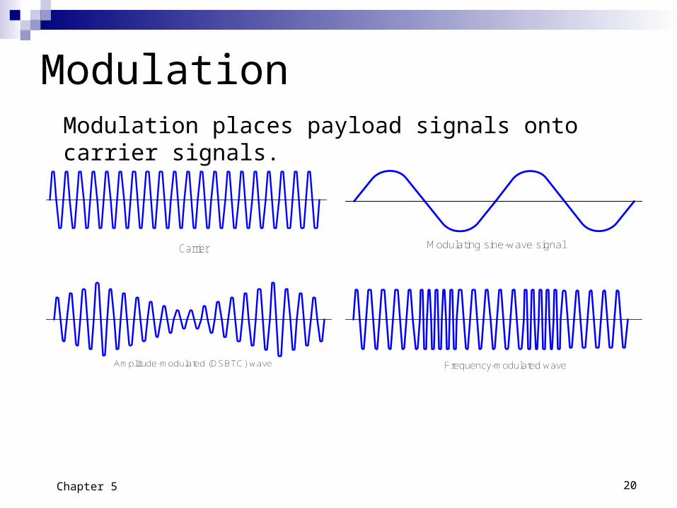
Carrier
Amplitude-modulated (DSBTC) wave Frequency-modulated wave
Modulating sine-wave signal
Modulation places payload signals onto carrier signals.

21Chapter 5
Amplitude Modulation (AM Radio)
Amplitude Modulation is used in AM Radio Music can be superimposed, or modulated, onto
the carrier wave by varying the amplitude of the carrier wave in correlation to the music signal.
Amplitude-modulated (DSBTC) wave

22Chapter 5
Frequency modulation (FM radio)
Frequency modulation is used in FM radio and television.
The analog music signal varies the frequency of the carrier wave.
Frequency-modulated wave

23Chapter 5
Television signals Television uses both amplitude and frequency
modulation to transmit the picture and sound to a television receiver.
Each channel has a 6 MHz bandwidth, superimposed onto a carrier wave range of 50-212 MHz for very high frequency (VHF) channels 2-13, and 450-900 MHz for ultrahigh frequency (UHF) channels 14-84.
The video signal uses amplitude modulation in the range of 0.5 to near 5.75 MHz, with color information being coded at 3.6 MHz using other AM techniques.
24Chapter 5
Signal transmission Neither analog nor digital signals can be
transmitted directly because of the noise in the environment, or as in the case of radio and television, the distance required.
We modulate the desired signals, such as voice and video, onto a carrier frequency, which can be transmitted further.

25Chapter 5
Broadband verses Baseband
Broadband generally refers to wide analog circuits, often divided into channels via Frequency Division Multiplexing (FDM).
Baseband means a single channel, usually with digital data.

26Chapter 5
Compression Compression increases the bandwidth of a
channel without adding or replacing circuits or channels.
Compression is used to reduce the amount of storage required and the amount of bandwidth required in transport by encoding series of occurrences of such things such as blank spaces in a document. This encoding reduces the redundancies transmitted.

27Chapter 5
Effective bandwidth Effective bandwidth is equal to the
channel’s native bandwidth, minus the effects of noise, plus that gained due to compression.
Multplexing
29Chapter 5
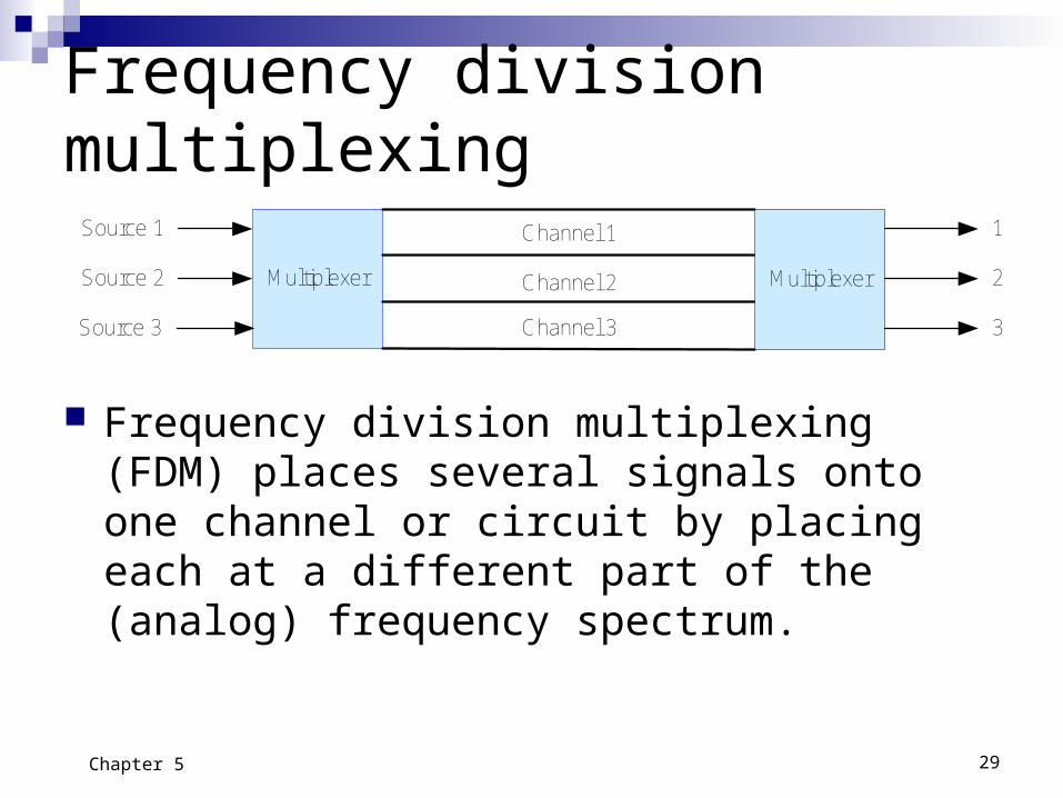
Frequency division multiplexing
Multiplexer Multiplexer
Channel 1
Channel 2
Channel 3
Source 1
Source 2
Source 3
2
3
1
Frequency division multiplexing (FDM) places several signals onto one channel or circuit by placing each at a different part of the (analog) frequency spectrum.

30Chapter 5
Four simultaneous transmissions on a single circuit
Computers Terminals
Multiplexer Multiplexer

31Chapter 5
Divided Channels
When a channel is established but not totally utilized, the potential exists to further divide the channel for additional uses.
Subsidiary communications authorization (SCA) uses subchannel transmission over the FM radio spectrum. Subchannel is a division of a channel, which may be a
division of a circuit.

32Chapter 5
Time division multiplexing Time division multiplexing (TDM) shares the circuit’s time
allocation. Simplistically, TDM physically switches from originator to
originator to share the time available, and the receiving unit does the same in synchronism.
Source 3
Multiplexer
Source 1
Source 2 2
3
1
1 2 3 1 2 3 1 2 3 1 2 3 1 2 3 Multiplexer

33Chapter 5
Time division multiplexing
An alternative method of TDM is for the controller to poll the slaves to see if each wishes to be connected.
Polling provides more control and requires more overhead, but as with statistical methods, active devices have more access time.

34Chapter 5
Statistical Time Division Multiplexing
Source 3
Multiplexer
Source 1
Source 2 2
3
1
Multiplexer1 1 1 3 2 1 1 2 3 1
A special form of TDM. Most common use has been the terminal-host
configuration, where the terminals attached to the CPU are not always transmitting.

35Chapter 5
Statistical Time Division multiplexing STDM shares a single line among multiple
sources on a non-uniform basis. The technology is cost effective in an
environment where multiple computers must communicate directly with other computers, where the time required varies by computer and time, and only a single communications channel is available (non-LAN environment).

Integrated Services Digital Network
37Chapter 5
Integrated Services Digital Network ISDN is a digital replacement of the analog
POTS telephone. ISDN is being used extensively in Western
Europe and Japan by business.
38Chapter 5
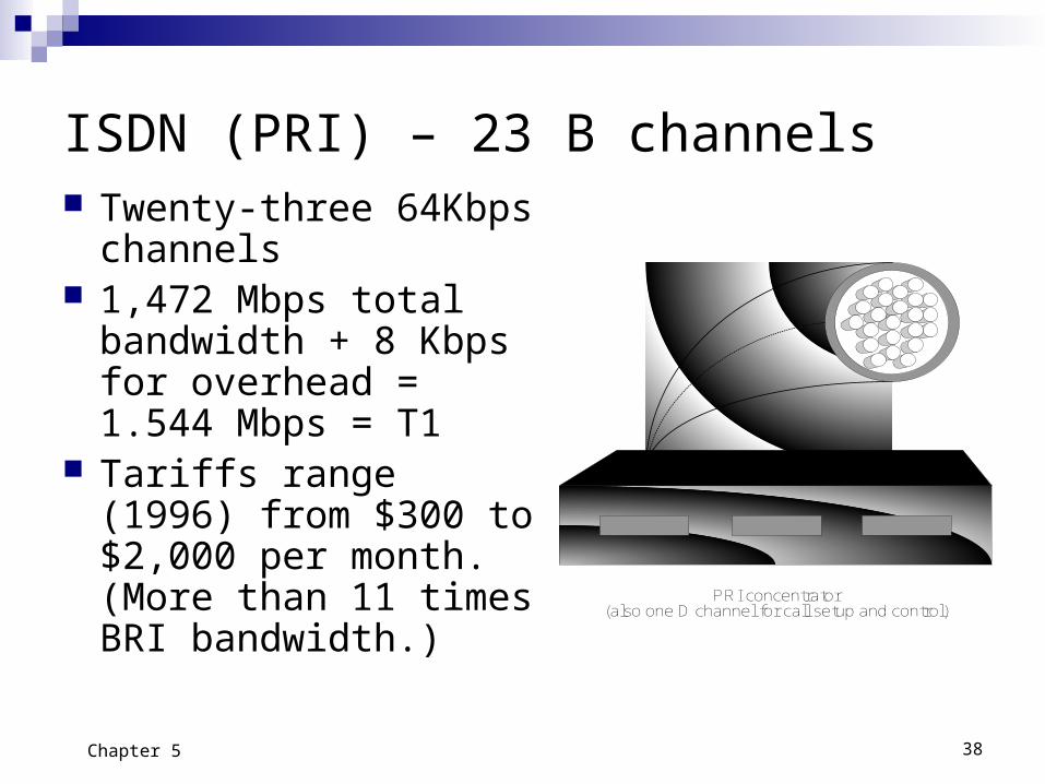
ISDN (PRI) – 23 B channels Twenty-three 64Kbps
channels 1,472 Mbps total
bandwidth + 8 Kbps for overhead = 1.544 Mbps = T1
Tariffs range (1996) from $300 to $2,000 per month. (More than 11 times BRI bandwidth.)
PRI concentrator(also one D channel for call setup and control)

39Chapter 5
ISDN (BRI) - Two B channels Two 64 Kbps (DS-0) bearer
channels per BRI line Bearer channels may be
added for 128 Kbps total bandwidth
One 16 Kbps data or delta channel for control and data
16 Kbps overhead Total bandwidth = 160 Kbps;
usable bandwidth = 144 Kbps Service tariffs can average
(1996) from $30 to $100 per circuit.
BRI concentrator(also one D channel)

40Chapter 5
T1 Leased line - 24 channels Twenty-four 64 Kbps
channels 1.544 Mbps total
bandwidth Service prices (1996)
range from $600 to $750 per month with some drops as low as $300 per month.
T1 leased line

41Chapter 5
POTS verses ISDN Telephone
Characteristics POTS ISDNLocal Loop Twisted-pair, copper Twisted-pair, copper
Channels 1 3
Bandwidth 2,700 Hz analog 160 Kbps digital
Noise level Medium Low and controllable
Signaling Touch-Tone® Data channel
End of Chapter 5
The Management of Telecommunications:
Houston H. Carr and Charles A. Snyder