Embed Size (px)
Citation preview

Data center upgrade proposal (phase one)

Data Center model review and recommendations
2
Executive Summary
Great Lakes began a recent dialogue with a customer regarding current operations and the potential for performance improvement
within the The customer data center.
After a series of initial conversations, the customer expressed a desire to gain an assessment of the current operational status of the
company’s data center, along with data center infrastructure management (DCIM) recommendations which could provide
multi-generational support as the company’s IT needs continue to evolve.
Great Lakes Case & Cabinet was contracted to provide a comprehensive evaluation of the customer’s Data Center and to conduct
complete computational fluid dynamics (CFD) analysis of the facility in its current form. Numerous site visits were conducted and
numerous on-site measurements were taken. The operational capabilities of the current data center were captured in a CFD to
establish baseline standards against which any potential future improvements might be measured.
Great Lakes was also asked to look at the short, medium and long term potential for increased density within the data center as well
as an expansion of IT operations within the space. As part of that effort, Great Lakes would offer infrastructure recommendations,
supported by CFD analysis which would create real world performance estimates of future operations within the data center, as those
recommendations might be implemented.
The following pages outline the scope of work performed by Great Lakes as well as the presentation of data collected, infrastructure recommendations made to
the management of the data center (along with estimates and ROI for recommended solutions) as well as CFD modeling designed to estimate data center
performance conditions as those recommendations might be implemented.

Overview - Phase 1 recommended action plan:
The following recommendations are described to increase the performance
and efficiency of the data center based on the modeling data and discussions
with the data center team.
Phase 1 includes:
Network Core tile migration— pg. 4-6
Migrating floor tiles— pg. 7
Removing under-floor baffle— pg. 8-9
Cold aisle and enclosure containment— pg. 10–16
Eliminate air re-circulation in current enclosures
Deployment of cold aisle containment
Core switch migration— pg. 17-18
Increasing CRAC unit set point (as desired)
Additional Information:
Recommended action plan— pg. 23
Bill of Materials— pg. 24
PUE, Cooling Cost Reduction and ROI— pg. 25
Conclusion— pg. 25

Data Center model review and recommendations
4
Network Core (Baseline)
Enclosure #207
Rendered view Rendered view with airflow patterns
Rendered view with airflow patterns
Enclosure 207 was chosen for an internal view to demonstrate the airflow
patterns inside the enclosure. The excess air introduced by the unsealed
cable cut-out lowers the temperatures inside the enclosures in the row
protecting the side-to-side airflow equipment from overheating.
207

Data Center model review and recommendations
5
Network Core (Phase 1)
Enclosure #207 Rendered view
Rendered view with airflow patterns
Rendered view with airflow patterns
Enclosure 207 was chosen for an internal view to demonstrate the airflow
patterns inside the enclosure. The excess air introduced by the unsealed
cable cut-out lowers the temperatures inside the enclosures in the row
protecting the side-to-side airflow equipment from overheating.
Perforated floor tiles have been moved to provide a higher flow of conditioned air to the equipment. A high
207

Data Center model review and recommendations
6
Network Core (Baseline)
Side to side airflow equipment creating a
cascading heat elevation scenario
Unblocked cable cutouts provide a supply
of cool air inside the enclosure
This reduces the temperature
cascading effect
Network Core (Rearranged floor tiles)
Floor tiles reorganized providing higher flow
of air directly in front of the enclosures
High flow tile installed in front of #207 to
provide additional airflow to core switches
in nearby enclosures
Sampling the temperatures at enclosure
#204 we can see a 7.1o Fahrenheit decline in
temperature.
Temp at 81.5o F
Temp at 74.4o F

Data Center model review and recommendations
7
Under-floor
Baseline
With the under-floor plenum installed, the secondary zone created is highly pressurized. In addition, there is minimal to no load in the
secondary zone. This greatly reduces the efficiency of the two CRAC units installed in the zone. It is recommended that this barrier be removed to allow the
two units to supply additional cooling to the entire room.
Entrance
Data Center model review and recommendations
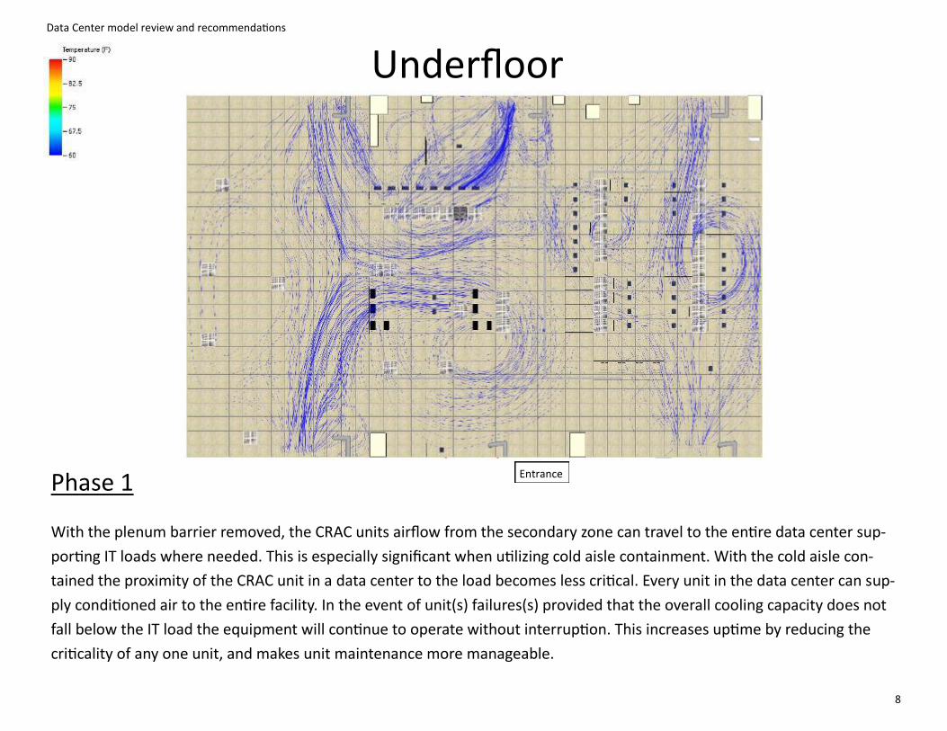
8
Phase 1
With the plenum barrier removed, the CRAC units airflow from the secondary zone can travel to the entire data center sup-
porting IT loads where needed. This is especially significant when utilizing cold aisle containment. With the cold aisle con-
tained the proximity of the CRAC unit in a data center to the load becomes less critical. Every unit in the data center can sup-
ply conditioned air to the entire facility. In the event of unit(s) failures(s) provided that the overall cooling capacity does not
fall below the IT load the equipment will continue to operate without interruption. This increases uptime by reducing the
criticality of any one unit, and makes unit maintenance more manageable.
Underfloor
Entrance

Data Center model review and recommendations
9
Tile Migration
Entrance
Tile migration for phase 1 development. By removing tiles in the hot aisle and locations not directly near IT equipment the under-floor pressure increases
creating a higher velocity of airflow to the equipment providing better cooling. In addition, by reducing the amount of conditioned air mixing with exhaust
air the return temperature to the CRAC units increases which increases the efficiency of the entire HVAC system.

Data Center model review and recommendations
10
Equipment Orientation—Baseline
Entrance
Shown is the current layout of enclosures and floor tiles in the data center. The red X on the CRAC unit indicates that it is currently non-operational.

Data Center model review and recommendations
11
Aisle completion with enclosures
Aisle completion: The following enclosures are recommended to complete the rows. These were based on discussions with IT and their future expansion plans.
GL840ES-2442 enclosures - qty 13 (2 enclosures will replace enclosures highlighted in red)
#1— Qty. 2
#2— Qty. 4 (6)
#3— Qty. 5
GL840ENT-3242MSS enclosures—qty 3
#5— Qty. 3
1
2
3
4

Data Center model review and recommendations
12
Equipment Orientation—Phase 1
Entrance
Phase 1 layout shows the completed rows, migrated tiles overhead panels and aisle doors are hidden to show cold aisles.

Data Center model review and recommendations
13
Server Farm (Baseline)
Unfinished rows increase potential for
recirculation of hot air
Open rack spaces create short circuits inside the
enclosure, allowing conditioned air to bypass
equipment and hot aisle to recirculate back into the
equipment intakes
Server Farm (Phase 1)
Additional enclosures complete rows and segregate hot
and conditioned air
Open rack spaces have filler panels installed to
reduce short circuits
Cisco 6500 switches migrated from EMC
enclosure to 30” wide enclosure
Floor tiles have been moved from other areas in the
datacenter to complete cold aisle
Model temperature comparison shows an 10.9o F
61.1o F
71.9o F

Data Center model review and recommendations
14
Server Farm Cold Aisle Containment
Shown is an overhead view of the complete aisles with containment doors at the end of the aisles and overhead containment panels containing conditioned
air in the cold aisle. This design was tested based on discussion with the data center team based on its ability to reduce the criticality of any one CRAC unit
failure, eliminates hot air re-circulation improving the performance and extending the life of the equipment.

Data Center model review and recommendations
15
San Switch Migration—Phase 1
Cisco Catalyst 6509-E core switches are migrated to two of the GL840ES-3048 enclosures in the 700 row.
Baffle kits are installed to prevent air recirculation from one switch to the next eliminating the potential
for cascading heat issues.

Data Center model review and recommendations
16
San Switch—Phase 1
(side view w/baffles)
Intake side (baffle side hidden)
Exhaust side
Baffles reduce recirculation by directing conditioned air toward the intake side and exhausting the hot air
toward the cold aisle. Used in conjunction with a brush grommet kit, side-to-side airflow operates efficient-
ly in a hot aisle/cold aisle configuration.

Data Center model review and recommendations
17
Baseline—Top View
Entrance
1
1. Highest temp in the cold aisle currently. Model data average temp 73.6F
2. Network core temps outside of the enclosure reach upwards of 75F
2
CRAC Unit Specifications
Set Point 72o F
Supply Temp. 61o F

Data Center model review and recommendations
18
Phase 1—Top View (Polargy panels hidden to make cold aisle visible)
Entrance
1
1. Cold aisle temp consistent at 62.2F
2. Network core temps outside of the enclosure at 73.4F
3. Migrated SAN switches are active and exhausting temps at 82F
By implementing containment, cold aisle temperatures are within a few degrees of under-floor tile supply. This
allows the CRAC units to be increased in one degree increments and cold aisle temps will increase accordingly.
2 3
CRAC Unit Specifications
Set Point 72o F
Supply Temp. 61o F

Data Center model review and recommendations
19
Baseline—Look Down View

Data Center model review and recommendations
20
Phase 1—Look Down View
SAN switch migration creating
temps of 87F

Data Center model review and recommendations
21
CRAC Unit Failure Analysis—Baseline
When the CRAC unit with the highest load on it (conditioning the most air in the data center) is shutdown, the hot air from
the server farm (specifically the blade server enclosures) travels to the next nearest unit. This increases the load on that unit
as well as increases the cold aisle temperatures. This scenario creates massive short cycling of hot air, increasing the
equipment intake temperatures, resulting in equipment “thermal-ing down/off” or failing.
90.1F Temp

Data Center model review and recommendations
22
When cold aisle containment is implemented and the CRAC unit is shut down the hot air continues to travel to the nearest
available unit. However, with the cold aisle contained a consistent flow of conditioned air is supplied into the aisle equipment
intakes; no hot air short cycling can occur, resulting in uninterrupted service in the event of a single unit failure.
Temps taken at enclosure 508 show a delta of 8 degrees Farenheit. In addition temps taken in the cold remain a consistent
60-63 degrees F.
CRAC Unit Failure Analysis— Phase One
82.1F Temp

Data Center model review and recommendations
23
Recommended Action Plan
Network Core tile migration— pg. 4-6
Migrating floor tiles— pg. 9
Removing under-floor baffle— pg. 7-8
Cold aisle and enclosure containment— pg. 10-14
Completing aisles with enclosures pg. 11-13
Eliminate air re-circulation in current enclosures
Install filler panels in open RMU
Install solid top panels— IT3
Install side panel blanks— IT4
Deployment of cold aisle containment
Install Polargy Polar-Plex panels— IT6
Install aisle containment doors— IT1/IT2
Core switch migration— pg. 15-16
Installation of Baffle Kits— ESSAB14
Increasing CRAC unit set point (as desired) - For every degree the set point is raised 4% efficiency gain*
*source: The American Society of Heating Refrigeration and Air Conditioning Engineers TC 9.9

Data Center model review and recommendations
24
PUE, Cooling Cost Reduction and ROI
PUE (Power Usage Effectiveness):
Average PUE for 2011 (based on data provided) 1.84
PUE estimate (after phase 1 completion) 1.39
Current and Projected cooling costs:
Current average monthly cooling cost (based on data provided) $4,153.38
Projected average monthly cooling cost $1,930.75
Estimated savings $2,222.63*
*Projected average savings and ROI can be improved by raising set point(s), reducing fan speed and cycling CRAC units. Performance will vary
based on system flexibility and tolerances

Data Center model review and recommendations
25
Conclusion:
Great Lakes has designed and modeled a solution that provides the customer with a data center upgrade plan designed to in-
crease the energy efficiency and reliability of their current design by segregating hot and cold air, optimizing air delivery, and
deploying cold aisle containment.
Recommendations:
1. Adjust the floor tiles providing airflow to the enclosures at the network core. Moving the tiles directly in front of the en-
closures will allow a greater supply of conditioned air to reach the equipment, greatly improving the exhaust tempera-
ture of the airflow equipment installed in the racks and lowering the internal enclosure temperatures. This effort will
result in a decreased risk of thermal issues: performance degradation, thermal shutdown, and early equipment
mortality.
2. Create and fully contain the cold aisles in the server farm. This can be achieved in several steps: redeploying and consoli-
dating floor tiles; completing the aisles with enclosures; installing filler panels in any unused RMU; and containing the
cold aisle through the use of end of row doors and overhead containment panels.
Through containment, the conditioned air is segregated from hot exhaust air. Contained conditioned air will remain at
delivered temperature until used by the equipment. Another advantage of cold aisle containment is consistency in cold
aisle temperatures which will be very close to the supply temperatures of the CRAC units. Any increase to the set points of
the CRAC unit should proportionally increase the conditioned air supplied to the cold aisle. This should make it much easi-
er to the deliver a consistent supply temperature to every piece of equipment.
Modeling revealed that the removal of the under floor baffle could increase the amount of cooling capacity to the entire
room. A fully open raised floor, in conjunction with cold aisle containment, could reduce the impact a single CRAC unit failure
will have on the data center. This scenario was modeled at the CRAC unit with the highest load in the server farm. Hot aisle
temperatures increased dramatically, while the cold aisle remained at supply temperatures. (pgs. 21-22)

Data Center model review and recommendations
26
Conclusion:
By completing the Phase 1 recommendations, the data centers
overall performance will be improved by:
Better utilizing the conditioned air
Balancing the load per CRAC unit more effectively
Increasing the available capacity (in RMU) on the datacenter floorspace
Significantly reducing recirculation in the enclosure
Improving reliability
Reduced intake temperatures increasing equipment lifespan
Balanced CRAC unit load reduces dependency on a single unit failure
Cold aisle containment allows the server equipment to continue operation even
when closest proximity CRAC unit fails