Embed Size (px)
Citation preview

© 2010 Cisco and/or its affiliates. All rights reserved. This document is Cisco Public Information.
Chapter 8
Data Center Design with VMware ESX 4.0 and Cisco Nexus 5000 and 1000V Series Switches 4.0(4)SV1(1)
and 2000 Series Fabric Extenders

Design Guide
© 2010 Cisco and/or its affiliates. All rights reserved. This document is Cisco Public Information. Page 2 of 42
Contents
Introduction 3 VMware vSphere Concepts 3
Why Distributed Switching? 3 VMware Traffic Requirements 4
Cisco Nexus 1000V Concepts 4 Virtual Supervisor Module 4
VSM Roles 5 VSM Network Adapters 5
VSM-to-VEM Communication 6 Opaque Data 7 Troubleshooting the VSM-to-VEM Connectivity 7 Domain 9
VSM-to-VMware vCenter Communication 9 VMware Distributed Resource Scheduler, High Availability, and Fault Tolerance 9 Port Profiles 10
Uplink Port Profiles 10 Regular Port Profiles 12 Link Between Port Profiles and Uplink Port Profiles 13
Ethernet Ports 13 Virtual Ethernet Ports 14
Layer 2 Forwarding and Loop Prevention with Cisco Nexus 1000V 14 Cisco Nexus 1000V Connected to Two Devices That Support Virtual PortChannels 15 Cisco Nexus 1000V Connected to Two Devices That Do Not Support vPC 15
PortChannel Capabilities on the Cisco Nexus 1000V 15 vPC Configuration with Link Aggregation Control Protocol 16 vPC Host Mode Configuration with Cisco Discovery Protocol 17 vPC Host Mode Configuration Without Cisco Discovery Protocol 17
Design Considerations with the Cisco Nexus 1000V 17 VSM Deployment Considerations 17 Uplink Port Profiles 22
Design with Cisco Nexus 5000 Series Switches (vPC Mode) and 10 Gigabit Ethernet Adapters 22 Design with Cisco Nexus 2148T Series Fabric Extender (vPC Mode) and Quad Gigabit Ethernet Adapters 25 Scaling the Design with Multiple Uplink Port Profiles 29
Design for VMware VMkernel 30 Overall Topology 32
Configuration Steps 34 Cisco Nexus 5000 Series Configuration 34 Configuration of the VSM 35
Configuring Redundancy 37 Initial VSM and Cisco Nexus 1000V Configuration 37
Configuring the System Port Profile 39 Adding VMware ESX Hosts to the Cisco Nexus 1000V 40 Configuring Uplink Port Profiles 41
Design Guide
© 2010 Cisco and/or its affiliates. All rights reserved. This document is Cisco Public Information. Page 3 of 42
Introduction
This chapter provides network design recommendations for the deployment of the Cisco Nexus® 1000V Switch
version 4.0(4)SV1(1) in a VMware vSphere environment.
This chapter assumes that the reader is familiar with the use of VMware ESX 3.5 with Cisco® networking
infrastructure prior to the introduction of the Cisco Nexus 1000V, as described at this URL:
http://www.cisco.com/application/pdf/en/us/guest/netsol/ns304/c649/ccmigration_09186a00807a15d0.pdf.
This chapter discusses the use of VMware vSphere and ESX 4 in conjunction with the Cisco Nexus 1000V and
complements the following publication:
http://www.cisco.com/en/US/prod/collateral/switches/ps9441/ps9902/guide_c07-556626.html.
Additional information about the Cisco Nexus 1000V can be found at these URLs:
● http://www.cisco.com/en/US/products/ps9902/index.html
● http://www.cisco.com/en/US/products/ps9902/product_solution_overview_list.html
The configuration guide for the Cisco Nexus 1000V can be found at this URL:
http://www.cisco.com/en/US/products/ps9902/products_installation_and_configuration_guides_list.html.
VMware vSphere Concepts
This design guide provides guidelines for the deployment of virtualized servers based on VMware vSphere:
http://www.vmware.com/products/vsphere/.
Compared with VMware Virtual Infrastructure 3 (http://www.vmware.com/products/vi/), VMware vSphere networking
includes the following networking improvements:
● Distributed switching with either the native VMware implementation, the VMware vNetwork Distributed Switch
(vDS), or the Cisco Nexus 1000V distributed virtual switch (DVS)
● Support for a new paravirtualized adapter, vmxnet3, which supports 10 Gigabit Ethernet speeds, Message
Signaled Interrupts Extension (MSI-X), receive-side scaling (RSS) when using Microsoft Windows Server
2008 as a guest OS, TCP segmentation offload, TCP, and User Datagram Protocol (UDP) checksum offload
● Better network performance as well as more I/O operations per second (IOPS)
Why Distributed Switching?
Distributed switching, with either the Cisco Nexus 1000V or VMware vDS, simplifies the provisioning of network
properties across the VMware ESX infrastructure.
With VMware vSphere, the user has the choice of deploying the following switching constructs and products:
● Standard virtual switch (vSwitch): This switch construct has local significance; it is provisioned per VMware
ESX host.
● VMware vNetwork Distributed Switch: This is a distributed switch. You can define the switching properties
for up to 64 VMware ESX hosts at a time, instead of having to configure each VMware ESX host individually
for networking. The VMware vNetwork Distributed Switch is configured through VMware vCenter.

Design Guide
© 2010 Cisco and/or its affiliates. All rights reserved. This document is Cisco Public Information. Page 4 of 42
● Cisco Nexus 1000V: This is a distributed switch (encompassing up to 64 VMware ESX hosts at a time), just
like the VMware vNetwork Distributed Switch with the additional benefit of that it can be configured through
the Cisco NX-OS Software command-line interface (CLI). The Cisco Nexus 1000V simplifies the separation of
roles between the network administrator, who manages the network configurations using the Cisco tools, and
the server administrator, who manages the virtual machines using VMware vCenter. Additional benefits
include security and switching features that simplify network troubleshooting and increase the security of
VMware deployments; these features are beyond the scope of this guide.
VMware vSphere introduces the concept of the distributed virtual port group (in contrast to regular port groups). A
distributed virtual port group has characteristics similar to a regular port group (virtual LAN [VLAN] assignment,
network interface card [NIC] teaming policy, quality-of-service [QoS] policy, etc.), but it is configured across multiple
VMware ESX hosts.
The Cisco Nexus 1000V is fully compatible with distributed virtual port groups, using a construct called the port
profile. A port profile as defined on the Cisco Nexus 1000V appears to VMware vCenter as a distributed virtual port
group.
VMware Traffic Requirements
The three most relevant traffic types that you need to consider when deploying virtualized servers are as follows:
● Virtual machine data traffic: You need to consider data traffic transmitted or received by virtual machines.
● VMware ESX management traffic: VMware vCenter Server requires access to the VMware ESX
management interface to monitor and configure the VMware ESX host.
● VMware VMkernel traffic: VMware VMotion uses the VMware VMkernel path to copy the memory from the
originating host to the destination VMware ESX host. VMware VMotion traffic does not constantly require a
high level of bandwidth, requiring high bandwidth only when VMware VMotion is initiated; it usually generates
a burst of data over a period of 10 to 60 seconds. The duration of the virtual machine migration is extended
based on the amount of bandwidth available. Because VMware VMotion processing is mainly a memory
operation, it can easily take advantage of connectivity that exceeds Gigabit Ethernet bandwidth.
Cisco Nexus 1000V Concepts
The Cisco Nexus 1000V is a distributed software switch. It consists of two main components: the virtual supervisor
module (VSM, the control-plane component) and the virtual Ethernet module (VEM, the data-plane component).
Together these components provide the abstraction of a physical switch, whose supervisor is the VSM and whose
line cards are the VEMs that run within each VMware ESX host.
All configurations are performed on the VSM and are propagated to the VEMs that are associated with it.
A VSM can be a virtual machine and can run redundantly just like a redundant supervisor. A single VSM can manage
up to 64 VEMs concurrently.
You can add a VMware ESX host to the Cisco Nexus 1000V vDS from VMware vCenter to make a VMware ESX host
become part of a Cisco Nexus 1000V domain, and as a result run a VEM.
Virtual Supervisor Module
A VSM running as a virtual machine provides the abstraction of a CLI managing a large modular switch. The user
uses Secure Shell (SSH) Protocol at the management interface of the VSM, or simply uses the console—that is, the
virtual machine console screen--to configure the network characteristics of the VMware deployment. Figure 1 shows
an example of the VSM console.

Design Guide
© 2010 Cisco and/or its affiliates. All rights reserved. This document is Cisco Public Information. Page 5 of 42
Figure 1. VSM Console
The VSM forwards the configurations (VLANs, QoS, private VLANs [VLANs], etc.) to all the VEMs that are part of the
same domain (discussed later in this chapter), or, in other words, that are under the same Cisco Nexus 1000V.
VSM Roles
VSMs are typically deployed in pairs, just like supervisors in a modular switch.
A VSM can run in one of the following roles:
● Active: Controls the system and is reachable for configurations as the mgmt0 interface of a physical switch
● Standby: Continuously monitors the active VSM to take over in case of switchover
● Standalone: Default role for the VSM when there is no other VSM peer with which to run redundantly
A dual-VSM configuration allows uninterrupted traffic forwarding with stateful switchover (SSO) when a failure occurs
in the VSM. The two VSMs operate in an active-standby capacity in which only one is active at any given time, while
the other acts as a standby backup. The two VSMs constantly synchronize the state and configuration to provide
transparent and stateful switchover of most services if the active VSM fails.
Useful commands to control the role configuration are as follows:
system redundancy role {standalone | primary | secondary}
show system redundancy status
copy running-config startup-config
VSM Network Adapters
The VSM has virtual machine requirements much like other more traditional guest operating systems. At a high level,
the VSM requires a single virtual CPU, 2 GB of dedicated RAM, and three virtual network adapters of type e1000.

Design Guide
© 2010 Cisco and/or its affiliates. All rights reserved. This document is Cisco Public Information. Page 6 of 42
The VSM requires three network adapters to carry these traffic types:
● User management interface: This interface is the equivalent of mgmt0 interface on a physical switch. This
interface is also the one that is used for VMware Virtual Infrastructure Methodology (VIM) over HTTPS
communication between the VSM and VMware vCenter. This is always Network Adapter 2.
● Ethernet out-of-band management interface (the control interface): This interface carries the low-level
control traffic between the VSM and the VEM. This is always Network Adapter 1.
● Packet interface: This interface is always the third interface on the VSM and is always Network Adapter 3 in
the virtual machine network properties.
The VSM is considered the authoritative container for all configuration information. If the connection between the
VSM and VMware vCenter Server is disrupted, the VSM helps ensure that any configuration changes that have been
made during this period of disrupted communication are propagated to VMware vCenter Server when the link is
restored.
Figure 2 shows the three adapters needed on the VSM and the type of adapter that the VSM requires (E1000). Three
port groups are defined for the VSM: control, management, and packet.
Figure 2. VSM Adapter Properties
VSM-to-VEM Communication
The following are the most important traffic types that make the VEMs and the VSM operate like a single entity:
● Control traffic: This traffic is generated by the Cisco Nexus 1000V and exchanged between the primary and
secondary VSMs as well as the VSMs and VEMs. It requires very little bandwidth (less than 10 KBps) but
demands absolute priority. Control traffic should be considered the most important traffic in a Cisco Nexus
1000V network.

Design Guide
© 2010 Cisco and/or its affiliates. All rights reserved. This document is Cisco Public Information. Page 7 of 42
● Packet traffic: Packet traffic is used to transport selected packets to the VSM for processing. The bandwidth
required for the packet interface is extremely low, and its use is intermittent. If Cisco Discovery Protocol and
Interior Gateway Management Protocol (IGMP) features are turned off, there is no packet traffic at all.
Control and packet VLANs are carried on the uplink from the VMware ESX server to the switch. For this reason, the
initial communication between the VSM and the VEM is aided by VMware vCenter to remove any dependency on the
success of the VSM-to-VEM communication, so that communication can begin even if the network configuration on
the uplinks is not yet functioning.
Opaque Data
The data that the VSM stores on VMware vCenter and as a result on the VEM is referred as opaque data.
This additional information is added to the VMware ESX host through VMware vCenter and can be verified from the
VMware ESX console as follows:
[root@tc-esx02 ~]# /usr/sbin/vemcmd show card
Card UUID type 2: 41483531-3341-5553-4537-33304e34524e
Card name: tc-esx02
Switch name: tc-n1kv04
Switch alias: DvsPortset-0
Switch uuid: e3 29 06 50 10 ea 06 a3-58 e6 63 f3 d9 1e a4 e7
Card domain: 1
Card slot: 1
VEM Control (AIPC) MAC: 00:02:3d:10:01:00
VEM Packet (Inband) MAC: 00:02:3d:20:01:00
VEM Control Agent (DPA) MAC: 00:02:3d:40:01:00
VEM SPAN MAC: 00:02:3d:30:01:00
Management IP address: 10.51.35.102
Max physical ports: 32
Max virtual ports: 216
Card control VLAN: 23
Card packet VLAN: 24
Processors: 4
Processor Cores: 4
Processor Sockets: 2
Physical Memory: 4293214208
Troubleshooting the VSM-to-VEM Connectivity
Each VEM has a MAC address on the control VLAN, and if the communication is properly established, the VSM sees
the VEMs. This connectivity can be verified by using the following command:
tc-n1kv04# show svs neighbor
Active Domain ID: 1
AIPC Interface MAC: 000c-2913-5f0c
Inband Interface MAC: 000c-2913-5f20
Src MAC Type Domain-id Node-id Last learnt (Sec. ago)

Design Guide
© 2010 Cisco and/or its affiliates. All rights reserved. This document is Cisco Public Information. Page 8 of 42
In this example, the VSM does not see any VEM, which indicates a problem in the networking configuration that is
required between the VSM and the VEM.
To trace the Layer 2 communication between the VSM and the VEM, view the Layer 2 forwarding table on the Cisco
Nexus 5000 Series Switch and look specifically for the MAC addresses listed in the output of the /usr/sbin/vemcmd
show card command and show svs neighbor: the VSM Asynchrnonous Inter Process Communication (AIPC) MAC
address and the VEM AIPC MAC address in the /vemcmd show command.
Upon successful configuration, the VSM and VEMs can communicate:
tc-n1kv04# show svs neighbors
Active Domain ID: 1
AIPC Interface MAC: 000c-2913-5f0c
Inband Interface MAC: 000c-2913-5f20
Src MAC Type Domain-id Node-id Last learnt (Sec. ago)
------------------------------------------------------------------------
0002-3d40-0102 VEM 1 0302 53.98
0002-3d40-0103 VEM 1 0402 46.00
When VSM-to-VEM communication is established, the VEMs appear in the VSM as if they were modules in a
modular switch:
tc-n1kv04# show module
Mod Ports Module-Type Model Status
--- ----- -------------------------------- ------------------ ------------
1 0 Virtual Supervisor Module Nexus1000V active *
3 248 Virtual Ethernet Module NA ok
4 248 Virtual Ethernet Module NA ok
Mod Sw Hw
--- --------------- ------
1 4.0(4)SV1(1) 0.0
3 4.0(4)SV1(1) 0.4
4 4.0(4)SV1(1) 0.4
Mod MAC-Address(es) Serial-Num
--- -------------------------------------- ----------
1 00-19-07-6c-5a-a8 to 00-19-07-6c-62-a8 NA
3 02-00-0c-00-03-00 to 02-00-0c-00-03-80 NA
4 02-00-0c-00-04-00 to 02-00-0c-00-04-80 NA
Mod Server-IP Server-UUID Server-Name
--- --------------- ------------------------------------ --------------------
1 10.51.35.114 NA NA
3 10.51.35.103 41483531-3341-5553-4538-31384e375632 tc-esx03.cisco.com

Design Guide
© 2010 Cisco and/or its affiliates. All rights reserved. This document is Cisco Public Information. Page 9 of 42
VEM-to-slot-number mapping can be modified by changing the host vmware id configuration line:
tc-n1kv04# show module vem counters
--------------------------------------------------------------------------------
Mod InNR OutMI InMI OutHBeats InHBeats InAipcMsgs OutTO OutTOC InsCnt RemCnt
--------------------------------------------------------------------------------
3 2 2 2 3924 2680 2852 0 0 2 1
4 2 3 3 3916 3806 5328 0 0 3 2
Domain
Since multiple VSM and VEMs can share the same control and packet VLANs, the system must be able to determine
which VSM goes with which VEM. The concept of the domain is used to bind VSM to VEMs (Figure 3).
Figure 3. The Domain ID “Joins” VEMs that Belong to the Same VSM as Part of the Same vDS
VSM-to-VMware vCenter Communication
The communication between VSM and VMware vCenter uses the management interface (mgmt0) on the VSM. The
protocol runs on HTTPS. The key information is provided to VMware vCenter by pointing the browser to the VSM IP
address and downloading the extension key, extension.xml, which is added to VMware vCenter as a plug-in.
VMware Distributed Resource Scheduler, High Availability, and Fault Tolerance
The Cisco Nexus 1000V supports VMware Distributed Resource Scheduler (DRS), High Availability (HA), and Fault
Tolerance (FT) for the virtual machines connected to it (specifically, the VEM).
For the VSM, as of 4.0(4)SV1(1), VMware DRS cannot be used to manage the VSM virtual machine, and neither
VMware FT nor HA can be used for the VSM virtual machine. In addition, the VSM should not be migrated with
VMware VMotion.

Design Guide
© 2010 Cisco and/or its affiliates. All rights reserved. This document is Cisco Public Information. Page 10 of 42
Port Profiles
As a first approximation, port profiles are the equivalent of a distributed virtual port group on a VMware vNetwork
Distributed Switch. Port profiles are used to configure interfaces. A port profile can be assigned to multiple interfaces,
giving them all the same configuration. Changes to the port profile can be propagated automatically to the
configuration of any interface assigned to it.
In the VMware vCenter Server, a port profile is represented as a distributed virtual port group. The virtual Ethernet
and Ethernet interfaces are assigned in VMware vCenter Server to a port profile to:
● Define port configuration by policy
● Apply a single policy across a large number of ports
● Support both virtual Ethernet and Ethernet ports
Figure 4 shows the different types of port profiles available when using the Cisco Nexus 1000V as a vDS.
Figure 4. Port Profiles Types
Cisco Nexus 1000V vDS
Uplink Port Profiles
Virtual Machine Data Port Profile
Older vSwitch Port Groups
vDS Folder
Networking View
Uplink Port Profiles
Port profiles that are configured as capability uplinks can be assigned by the server administrator to physical ports
(vmnics).
An uplink port profile can also be a system port profile. An uplink port profile is a system port profile when it carries
the system VLANs used for the communication between the VSM and the VEM.
The system port profiles are used to carry the system VLANs:
● System VLANs cannot be deleted when the profile is in use.
● Nonsystem VLANs in a system port profile can be freely added or deleted, even when the profile is in use: that
is, when one or more vDS ports are carrying that profile.
● System VLANs can always be added to a system port profile or a nonsystem port profile, even when the
profile is in use.
● The native VLAN on a system port profile can be a system VLAN or a nonsystem VLAN.

Design Guide
© 2010 Cisco and/or its affiliates. All rights reserved. This document is Cisco Public Information. Page 11 of 42
A typical configuration of an uplink port profile that is also a system port profile looks like this:
port-profile system-uplink
capability uplink
vmware port-group fabric_uplinks
switchport mode trunk
switchport trunk allowed vlan 23-24
<channel-group configuration>
no shutdown
system vlan 23-24
state enabled
Some parameters in this configuration are of special interest:
● capability uplink: This parameter indicates that this port profile is to be used on the physical NICs.
● system vlan: This parameter makes this particular uplink port profile also a system port profile. The most
common use of system vlan is to add the packet and control VLANs to this port profile. These VLANs still
need to be configured under switchport trunk for them to be forwarding.
● state enabled: This parameter indicates that the configuration should be implemented on to all the hosts that
are associated with the Cisco Nexus 1000V DVS.
Every VMware ESX host must have at least one physical interface associated with a system port profile. Without this
port profile, the Cisco Nexus 1000V associations with the VMware ESX host can still happen, but the VEMs will not
appear as line cards or modules on the VSM.
The system VLANs have a special meaning because they are granted network communication in a preferential way
over the regular VLANs, so that even if the PortChannel configuration on the uplink port profile is not fully functional,
the VSM can still configure the VEM.
In the absence of the system VLAN definition, the VEM connectivity would be dependent on a successful
PortChannel configuration on the VSM. But this configuration would require a preexistent functioning PortChannel
configuration to help ensure VSM-to-VEM connectivity. The system VLAN configuration removes this dependency,
allowing the VSM to configure the VEM even if the PortChannel setup has not yet been completed for the virtual
machine production VLANs.
You can assign vmnics to an uplink port profile when you add a VMware ESX host to the Cisco Nexus 1000V from
VMware vCenter and you select the distributed virtual uplink port profile.
This association can be modified later as shown in Figure 5, by selecting a VMware ESX host and selecting the
Networking configuration, the Distributed Virtual Switch view, and then Manage Physical Adapters.

Design Guide
© 2010 Cisco and/or its affiliates. All rights reserved. This document is Cisco Public Information. Page 12 of 42
Figure 5. vmnic to Uplink Port Profile Association
After the VEMs are associated with the VSM, the network adapters of the VMware ESX hosts appear as a Ethernet
module and port as follows:
interface Ethernet4/4
inherit port-profile system-uplink
interface Ethernet4/5
inherit port-profile system-uplink
Regular Port Profiles
Regular port profiles are assigned to virtual machine virtual adapters. In Cisco Nexus 1000V terminology, these
virtual adapters are referred to as virtual Ethernet (vEth) interfaces.
A regular port profile is defined as follows:
port-profile vm-connectivity
vmware port-group connectivity-via-quad-gige
switchport mode access
switchport access vlan 50
no shutdown
state enabled
This would appear on the VMware vCenter server as shown in Figure 6, listed as one of the distributed virtual port
groups.

Design Guide
© 2010 Cisco and/or its affiliates. All rights reserved. This document is Cisco Public Information. Page 13 of 42
Figure 6. Regular Port Profiles Appear as a Distributed Virtual Port Group
Link Between Port Profiles and Uplink Port Profiles
Virtual machines attach to port profiles through the choice of the distributed virtual port group from the VMware
vCenter configuration. The association between the port profile and a VLAN defines the way the traffic flows from the
virtual machine to the outside network.
You can have multiple uplink port profiles for each VMware ESX host, but they cannot have overlapping VLANs,
which would break the uniqueness of the association.
By defining which VLAN is on which port profile and on which uplink port profile, you can control which path the virtual
machines take to communicate to the rest of the network.
Ethernet Ports
With the Cisco Nexus 1000V, the network ports can be of two types:
● Ethernet module and port: The module represents the VMware ESX host, and the port is one of the physical
NICs. This port type is used as an uplink. It is equivalent to a vmnic in VMware terminology.
● Virtual Ethernet ports: A vEth port is equivalent to a vnic in VMware terminology. These ports have a
number that is preserved should the virtual machine move from one VMware ESX host to a different one.

Design Guide
© 2010 Cisco and/or its affiliates. All rights reserved. This document is Cisco Public Information. Page 14 of 42
Virtual Ethernet Ports
When you configure a virtual machine, you can choose the adapter for the virtual machine and the distributed virtual
port group to which that the adapter attaches as shown in Figure 7.
Figure 7. Adapter Selection from the VM Configuration Properties
As you can see in this example, the virtual machine is configured to use the network label connectivity-via-quad-gige,
which is a Cisco Nexus 1000V port profile. The user can also select the proper adapter. The choice of the adapter is
beyond the scope of this guide. For a Gigabit Ethernet configuration, an e1000 or a vmxnet2 are sufficient.
For a 10 Gigabit Ethernet deployment, vmxnet3 allows you to take better advantage of the 10 Gigabit Adapter
acceleration features.
When the virtual machine is up, the vEth associated with it appears in the Cisco Nexus 1000V CLI as follows:
Vethernet1 is up
Port description is vm1-esx07-chariot, Network Adapter 2
Hardware is Virtual, address is 0050.5686.12e4
Owner is VM "vm1-esx07-chariot", adapter is Network Adapter 2
Layer 2 Forwarding and Loop Prevention with Cisco Nexus 1000V
The Cisco Nexus 1000V forwards Layer 2 traffic according to transparent bridging rules that have been modified for a
virtualized server environment. Each VEM within a Cisco Nexus 1000V maintains a Layer 2 forwarding table
independently from the other VMware ESX hosts.
The entries related to the virtual machines locally attached are programmed statically, while the MAC address entries
associated with the uplinks are dynamically learned.

Design Guide
© 2010 Cisco and/or its affiliates. All rights reserved. This document is Cisco Public Information. Page 15 of 42
The Cisco Nexus 1000V does not run any spanning tree (and hence also does not send Bridging Protocol Data Units
[BPDUs]). Loop prevention with multiple physical NICs connected to a Layer 2 topology is achieved by a combination
of PortChannels and MAC address pinning.
Cisco Nexus 1000V Connected to Two Devices That Support Virtual PortChannels
The simplest scenario is a Cisco Nexus 1000V connected to two upstream switches that support virtual PortChannel
(vPC) capability. In this case, the configuration of the port profile consists of a single channel group spanning both
upstream switches. No special loop prevention mechanism is required in this case.
Cisco Nexus 1000V Connected to Two Devices That Do Not Support vPC
If the Cisco Nexus 1000V is connected to two devices that do not support vPC, it divides the physical NICs into two
groups either automatically or through a subgroup ID configuration (defined by the network administrator). To prevent
loops, the Cisco Nexus 1000V behaves as shown in Figure 8. If a frame enters the VEM from one uplink, it will not be
reflected back on any other uplink. If a frame originates from a virtual machine (such as VM11 in the figure) and it
appears on one of the uplinks of the VMware ESX host where VM11 exists, this frame will be dropped.
Figure 8. Loop Prevention Without Spanning Tree
PortChannel Capabilities on the Cisco Nexus 1000V
A user can configure redundant connectivity from the VMware ESX host to the upstream switches by configuring an
uplink port profile with a PortChannel.
The simplest configuration specifies channel-group auto mode on in the uplink port profiles.
If the ports that are using the same port profile are going to different upstream switches, vPC is required if it is
supported by the upstream switches.

Design Guide
© 2010 Cisco and/or its affiliates. All rights reserved. This document is Cisco Public Information. Page 16 of 42
Several possible configuration scenarios exist based on whether the upstream switches are capable or configured to
support PortChannels. vPC host mode is a feature on the Cisco Nexus 1000V that allows interoperating with switches
that are not configured for PortChannels on all ports that connect to the VMware ESX host. vPC host mode can also
use Cisco Discovery Protocol to discover to which device each port is connected, to configure the uplinks correctly.
vPC Configuration with Link Aggregation Control Protocol
In the best scenario, an VMware ESX server is connected to an access switch that is vPC capable. In this case, the
Cisco Nexus 1000V can be configured with uplinks split to two access switches that form a vPC.
Link Aggregation Control Protocol (LACP) would be used both on the upstream switch and in on the Cisco Nexus so
that the PortChannel goes up as a result of the negotiation between the Cisco Nexus 1000V and the access
switches.
In the following uplink configuration, the PortChannel is configured for LACP and active mode is used on the Cisco
Nexus 1000V:
port-profile system-uplink
capability uplink
vmware port-group fabric_uplinks
switchport mode trunk
switchport trunk allowed vlan 23-24,50
channel-group auto mode active
no shutdown
system vlan 23-24
state enabled
A successful configuration will show the VMware ESX vmnic ports in the P state as shown here:
tc-n1kv04# show port-channel summary
Flags: D - Down P - Up in port-channel (members)
I - Individual H - Hot-standby (LACP only)
s - Suspended r - Module-removed
S - Switched R - Routed
U - Up (port-channel)
--------------------------------------------------------------------------------
Group Port- Type Protocol Member Ports
Channel
--------------------------------------------------------------------------------
2 Po2(SU) Eth LACP Eth4/4(P) Eth4/5(P)
3 Po3(SU) Eth LACP Eth6/3(P) Eth6/5(P)
This configuration shows that the channel group numbers (2 and 3) are dynamically generated. The Gigabit Ethernet
uplinks Eth6/3 and 6/5 are connected to two Cisco Nexus 2000 Series Fabric Connectors configured for vPC, and the
10 Gigabit Ethernet ports Eth4/4 and 4/5 are directly connected to two Cisco Nexus 5000 Series Switches configured
for vPC.
If you are using Cisco NX-OS Release 4.1(3)N1 on the Cisco Nexus 5000 Series and the LACP negotiation does not
complete correctly, the cause may be a problem (big ID CSCtb84803) that was fixed in Cisco NX-OS Release
4.1(3)N2(1). Also, if you are using first-generation converged network adapter (CNA) 10 Gigabit Ethernet cards and
LACP negotiation is not successful, you may need to disable lldp transmit on the Cisco Nexus 5000 Series 10
Gigabit Ethernet ports as follows:
(config-if)#no lldp transmit

Design Guide
© 2010 Cisco and/or its affiliates. All rights reserved. This document is Cisco Public Information. Page 17 of 42
vPC Host Mode Configuration with Cisco Discovery Protocol
When the two upstream switches support Cisco Discovery Protocol but do not support vPC, the configuration of the
port profile is as follows:
port-profile system-uplink
capability uplink
channel-group auto mode on sub-group cdp
vPC Host Mode Configuration Without Cisco Discovery Protocol
If the upstream switches do not support Cisco Discovery Protocol or vPC, the network administrator needs to split the
interfaces into groups (subgroups).
Under the main port profile, the configuration is as before:
port-profile system-uplink
capability uplink
channel-group auto mode on sub-group cdp
Because the upstream switches do not support Cisco Discovery Protocol, ports will be operationally down until you
configure subgroup IDs on the member ports as follows:
interface Ethernet3/4
description to_access_switch_1
inherit port-profile system-uplink
sub-group-id 0
channel-group 3 force
!
interface Ethernet3/5
description to_access_switch_2
inherit port-profile system-uplink
sub-group-id 1
channel-group 3 force
!
Design Considerations with the Cisco Nexus 1000V
VSM Deployment Considerations
The VSM can run attached to a standard vSwitch or to a VEM. Both configurations are possible. This guide focuses
on the use of VSM attached to a standard vSwitch. With this approach, the control plane is not dependent on the
forwarding plane that it is managing.
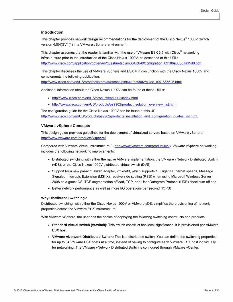
The server running the VSM is connected through 10 Gigabit Ethernet interfaces to the Cisco Nexus 5000 Series
Switch and with dual lights-out management (LOM) to the management network (Figure 9).
Design Guide
© 2010 Cisco and/or its affiliates. All rights reserved. This document is Cisco Public Information. Page 18 of 42
Figure 9. Example of a VSM Placement in a vPC Design with Servers Equipped with 10 Gigabit Ethernet Adapters
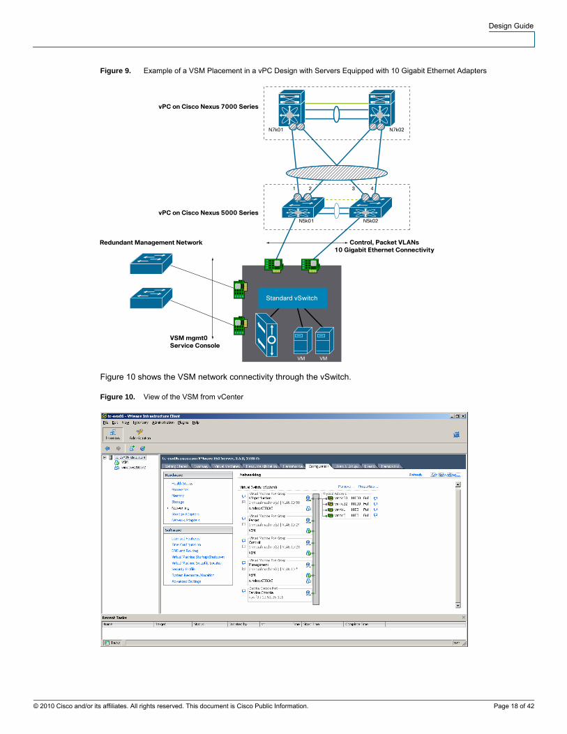
Figure 10 shows the VSM network connectivity through the vSwitch.
Figure 10. View of the VSM from vCenter

Design Guide
© 2010 Cisco and/or its affiliates. All rights reserved. This document is Cisco Public Information. Page 19 of 42
If the Cisco Nexus 5000 Series Switch is configured to support vPC, which is highly desirable when you deploy
VMware, then you should also configure the control and packet port groups for PortChannels as shown in Figure 11.
Figure 11. PortChannel Teaming Configuration on the vSwitch for Packet and Control VLAN
Load Balancing is set to Route based on source MAC hash because the packet and control VLANs at the time of
this writing cannot be routed. Under Active Adapters, you would list only the 10 Gigabit Ethernet adapters, and the
LOM interfaces would be on the Unused Adapters list for this port group.
The configuration on the primary Cisco Nexus 5000 Series Switch would be as follows:
tc-nexus5k01(config)# int eth1/6
tc-nexus5k01(config-if)# channel-group 6 mode on
tc-nexus5k01(config-if)# int po6
tc-nexus5k01(config-if)# vpc 6
tc-nexus5k01(config-if)#int po6
tc-nexus5k01(config-if)# switchport
tc-nexus5k01(config-if)# switchport mode trunk
tc-nexus5k01(config-if)# switchport trunk allowed vlan 23-24
tc-nexus5k01(config-if)# spanning-tree port type edge trunk

Design Guide
© 2010 Cisco and/or its affiliates. All rights reserved. This document is Cisco Public Information. Page 20 of 42
The configuration on the secondary Cisco Nexus 5000 Series Switch would be as follows (identical):
tc-nexus5k01(config)# int eth1/6
tc-nexus5k01(config-if)# channel-group 6 mode on
tc-nexus5k01(config-if)# int po6
tc-nexus5k01(config-if)# vpc 6
tc-nexus5k01(config-if)#int po6
tc-nexus5k01(config-if)# switchport
tc-nexus5k01(config-if)# switchport mode trunk
tc-nexus5k01(config-if)# switchport trunk allowed vlan 23-24
tc-nexus5k01(config-if)# spanning-tree port type edge trunk
Enter a show vpc brief command on the Cisco Nexus 5000 Series Switch to confirm whether the configuration was
completed correctly:
vPC status
----------------------------------------------------------------------------
id Port Status Consistency Reason Active vlans
------ ----------- ------ ----------- -------------------------- -----------
6 Po6 up success success 23-24
If the configuration does not show success, typical causes include lack of configuration of the control and packet
VLANs on the peer link.
You may also want to verify whether any Type-1 or Type 2 inconsistency occurred on the Cisco Nexus 5000 Switch
for those vPC ports:
tc-nexus5k01# show vpc consistency-parameters int po6
Legend:
Type 1 : vPC will be suspended in case of mismatch
Name Type Local Value Peer Value
------------- ---- ---------------------- -----------------------
STP Port Type 1 Edge Trunk Port Edge Trunk Port
STP Port Guard 1 None None
STP MST Simulate PVST 1 Default Default
mode 1 on on
Speed 1 10 Gb/s 10 Gb/s
Duplex 1 full full
Port Mode 1 trunk trunk
Native Vlan 1 1 1
Shut Lan 1 No No
Allowed VLANs - 23-24 23-24
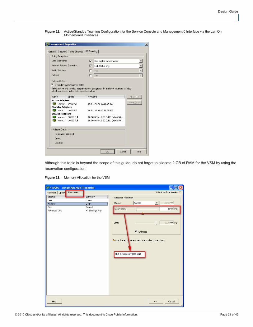
For mgmt0, you can use the classic active-standby behavior on the LOMs that are also used by the service console
(Figure 12).
Design Guide
© 2010 Cisco and/or its affiliates. All rights reserved. This document is Cisco Public Information. Page 21 of 42
Figure 12. Active/Standby Teaming Configuration for the Service Console and Management 0 Interface via the Lan On Motherboard Interfaces
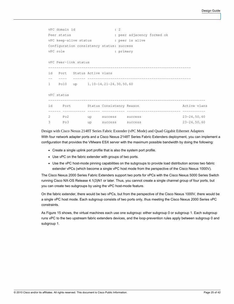
Although this topic is beyond the scope of this guide, do not forget to allocate 2 GB of RAM for the VSM by using the
reservation configuration.
Figure 13. Memory Allocation for the VSM

Design Guide
© 2010 Cisco and/or its affiliates. All rights reserved. This document is Cisco Public Information. Page 22 of 42
The initial configuration on the VSM needs to reflect the control and packet VLANs that have been chosen and the
domain ID. Here is an example of the configuration:
vlan 23
name control_vlan
vlan 24
name packet_vlan
svs-domain
domain id 1
control vlan 23
packet vlan 24
svs mode L2
Uplink Port Profiles
The uplink port profile configuration is the most relevant configuration for the connectivity between the Cisco Nexus
1000V and the upstream switches.
Every VMware ESX host must have at least one interface associated with a system uplink port profile to help ensure
VSM-to-VEM communication.
In addition to the system VLANs, the uplink port profiles need to carry primarily the virtual machine production
VLANs, VMware VMkernel traffic, and, potentially, service console traffic (which in this guide is configured on the
LOM ports).
If you use a unique uplink port profile, it will also be a system port profile, and the system VLAN will include packet
and control VLANs. If the service console uses the Cisco Nexus 1000V path, the service console VLAN should be
listed as one of the system VLANs.
Depending on the capabilities of the upstream switch, several designs are possible.
Design with Cisco Nexus 5000 Series Switches (vPC Mode) and 10 Gigabit Ethernet Adapters
This is the simplest configuration: You configure channel-group auto mode active (or passive, or on) in the uplink
port profile. The active and passive modes are preferred because of the LACP negotiation capabilities.
A typical topology, shown in Figure 14, consists of VMware ESX servers with two 10 Gigabit Ethernet ports with
CNAs (which can also concurrently support TCP/IP traffic and Fibre Channel over Ethernet [FCoE] traffic).

Design Guide
© 2010 Cisco and/or its affiliates. All rights reserved. This document is Cisco Public Information. Page 23 of 42
Figure 14. Cisco Nexus 1000V Topology with vPC on the Cisco Nexus 5000 Series Switches
In this case, the following configurations characterize the design:
● This design requires the creation of one uplink port profile.
● The uplink port profile is also a system port profile, so it carries system VLANs (control and packet).
● The VMware ESX network adapters are connected to both Cisco Nexus 5000 Series Switches.
● The uplink port profile is configured with channel-group auto mode active.
● The system VLANs are defined twice in the uplink port profile: under the system vlan configuration and as
allowed VLANs in the switchport trunk allowed vlan configuration.
● The upstream Cisco Nexus 5000 Series Switch is configured for vPC.
● The system VLANs are trunked on the Cisco Nexus 5000 Series vPC ports as well as on the peer link
(because of vPC).
● The spanning-tree root and secondary roots for system VLANs and VMware VMkernel VLANs are defined as
one of the Cisco Nexus 5000 Series Switches if the VMware ESX cluster exists only in the context of the
Cisco Nexus 5000 vPC pair or as one of the Cisco Nexus 7000 Series Switches if these VLANs span multiple
Cisco Nexus 5000 Series Switches.
● If the VMware ESX cluster is spread across more than one Cisco Nexus 5000 Series Switch, it is better to
place the root for all the VLANs listed above on the Cisco Nexus 7000 Series Switch. In this case, the system
VLANs and the VMware VMkernel VLAN are trunked to the upstream Cisco Nexus 7000 Series Switch.

Design Guide
© 2010 Cisco and/or its affiliates. All rights reserved. This document is Cisco Public Information. Page 24 of 42
The port profile configuration for the channel group is as follows:
port-profile system-uplink
capability uplink
vmware port-group fabric_uplinks
switchport mode trunk
switchport trunk allowed vlan 23-24, <production vlans>, <vmkernel vlan>
channel-group auto mode active
no shutdown
system vlan 23-24
state enabled
The configuration on each Cisco Nexus 5000 vPC peer would be as follows:
interface Ethernet1/2
description tc-esx02
switchport mode trunk
switchport trunk allowed vlan 23-24, <production vlans>, <vmkernel vlan>
untagged cos 0
spanning-tree port type edge trunk
channel-group 2 mode passive
interface port-channel2
switchport mode trunk
switchport trunk allowed vlan 23-24, <production vlans>, <vmkernel vlan>
vpc 2
spanning-tree port type edge trunk
spanning-tree bpdufilter enable
speed 10000
When you enter the show port-channel summary command, you should see that all the PortChannels on the Cisco
Nexus 1000V are in P mode:
tc-n1kv04# show port-channel summary
Flags: D - Down P - Up in port-channel (members)
I - Individual H - Hot-standby (LACP only)
s - Suspended r - Module-removed
S - Switched R - Routed
U - Up (port-channel)
--------------------------------------------------------------------------------
Group Port- Type Protocol Member Ports
Channel
--------------------------------------------------------------------------------
1 Po1(SU) Eth NONE Eth3/3(P) Eth3/4(P)
2 Po2(SU) Eth LACP Eth4/4(P) Eth4/5(P)
On the Cisco Nexus 5000 Series Switch, you also should see that the vPCs are in the up state:
tc-nexus5k01# show vpc br
Legend:
(*) - local vPC is down, forwarding via vPC peer-link
Design Guide
© 2010 Cisco and/or its affiliates. All rights reserved. This document is Cisco Public Information. Page 25 of 42
vPC domain id : 2
Peer status : peer adjacency formed ok
vPC keep-alive status : peer is alive
Configuration consistency status: success
vPC role : primary
vPC Peer-link status
---------------------------------------------------------------------
id Port Status Active vlans
-- ---- ------ --------------------------------------------------
1 Po10 up 1,10-14,21-24,30,50,60
vPC status
----------------------------------------------------------------------------
id Port Status Consistency Reason Active vlans
------ ----------- ------ ----------- -------------------------- -----------
2 Po2 up success success 23-24,50,60
3 Po3 up success success 23-24,50,60
Design with Cisco Nexus 2148T Series Fabric Extender (vPC Mode) and Quad Gigabit Ethernet Adapters
With four network adapter ports and a Cisco Nexus 2148T Series Fabric Extenders deployment, you can implement a
configuration that provides the VMware ESX server with the maximum possible bandwidth by doing the following:
● Create a single uplink port profile that is also the system port profile.
● Use vPC on the fabric extender with groups of two ports.
● Use the vPC host-mode pinning capabilities on the subgroups to provide load distribution across two fabric
extender vPCs (which become a single vPC host mode from the perspective of the Cisco Nexus 1000V).
The Cisco Nexus 2000 Series Fabric Extenders support two ports for vPCs with the Cisco Nexus 5000 Series Switch
running Cisco NX-OS Release 4.1(3)N1 or later. Thus, you cannot create a single channel group of four ports, but
you can create two subgroups by using the vPC host-mode feature.
On the fabric extender, there would be two vPCs, but from the perspective of the Cisco Nexus 1000V, there would be
a single vPC host mode. Each subgroup consists of two ports only, thus meeting the Cisco Nexus 2000 Series vPC
constraints.
As Figure 15 shows, the virtual machines each use one subgroup: either subgroup 0 or subgroup 1. Each subgroup
runs vPC to the two upstream fabric extenders devices, and the loop-prevention rules apply between subgroup 0 and
subgroup 1.

Design Guide
© 2010 Cisco and/or its affiliates. All rights reserved. This document is Cisco Public Information. Page 26 of 42
Figure 15. Cisco Nexus 1000V Topology with vPC on the Cisco Nexus 2148T
On the Cisco Nexus 1000V, you configure an uplink and system port profile as follows:
port-profile uplink-quad-gige
capability uplink
vmware port-group uplink-quad-gige
switchport mode trunk
switchport trunk allowed vlan 23-24, <production vlans>, <vmkernel vlan>
channel-group auto mode on sub-group cdp
no shutdown
system vlan 23-24
state enabled
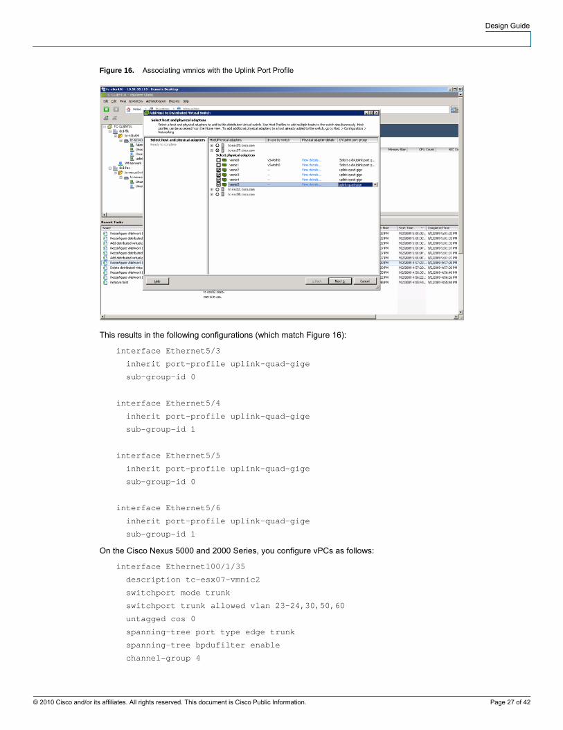
You then add the VMware ESX host to the Cisco Nexus 1000V and associate the vmnics with the distributed virtual
uplink port group as shown in Figure 16.
Design Guide
© 2010 Cisco and/or its affiliates. All rights reserved. This document is Cisco Public Information. Page 27 of 42
Figure 16. Associating vmnics with the Uplink Port Profile
This results in the following configurations (which match Figure 16):
interface Ethernet5/3
inherit port-profile uplink-quad-gige
sub-group-id 0
interface Ethernet5/4
inherit port-profile uplink-quad-gige
sub-group-id 1
interface Ethernet5/5
inherit port-profile uplink-quad-gige
sub-group-id 0
interface Ethernet5/6
inherit port-profile uplink-quad-gige
sub-group-id 1
On the Cisco Nexus 5000 and 2000 Series, you configure vPCs as follows:
interface Ethernet100/1/35
description tc-esx07-vmnic2
switchport mode trunk
switchport trunk allowed vlan 23-24,30,50,60
untagged cos 0
spanning-tree port type edge trunk
spanning-tree bpdufilter enable
channel-group 4

Design Guide
© 2010 Cisco and/or its affiliates. All rights reserved. This document is Cisco Public Information. Page 28 of 42
interface port-channel4
switchport mode trunk
switchport trunk allowed vlan 23-24,30,50,60
vpc 4
spanning-tree port type edge trunk
spanning-tree bpdufilter enable
speed 1000
interface Ethernet100/1/36
description tc-esx07-vmnic3
switchport mode trunk
switchport access vlan 50
switchport trunk allowed vlan 23-24,30,50,60
untagged cos 0
spanning-tree port type edge trunk
spanning-tree bpdufilter enable
channel-group 5
interface port-channel5
switchport mode trunk
switchport access vlan 50
switchport trunk allowed vlan 23-24,30,50,60
vpc 5
spanning-tree port type edge trunk
spanning-tree bpdufilter enable
speed 1000
Use the show command to verify that the two virtual machines, VM1-ESX07 and VM2-ESX07, are pinned to
subgroup 0 and subgroup 1, respectively. You can also see that vmnic2 and vmnic4 are part of the PortChannel
associated with subgroup 0, and that vmnic3 and vmnic5 are part of the PortChannel associated with subgroup 1:
[root@tc-esx07 ~]# /usr/sbin/vemcmd show port
LTL IfIndex Vlan Bndl SG_ID Pinned_SGID Type Admin State CBL Mode Nam
17 1a040200 1 T 303 0 2 PHYS UP UP 1 Trunk vmnic2
18 1a040300 1 T 303 1 2 PHYS UP UP 1 Trunk vmnic3
19 1a040400 1 T 303 0 2 PHYS UP UP 1 Trunk vmnic4
20 1a040500 1 T 303 1 2 PHYS UP UP 1 Trunk vmnic5
47 1b040000 50 0 2 0 VIRT UP UP 4 Access vm1-esx07
48 1b040010 50 0 2 1 VIRT UP UP 4 Access vm2-esx07

Design Guide
© 2010 Cisco and/or its affiliates. All rights reserved. This document is Cisco Public Information. Page 29 of 42
Tune the PortChannel load-balancing algorithm with this command:
tc-n1kv04(config)# port-channel load-balance ethernet source-ip-port
You can use all four available paths. When virtual machine 2 is sending traffic, this traffic is hashed according to the
PortChannel load-balancing algorithm previously selected and could end up on eth5/4 or eth5/6 from the perspective
of the Cisco Nexus 1000V, which is eth100/1/36 or eth101/1/36 from the perspective of the Cisco Nexus 5000 Series
Switch.
If eth100/1/35 fails, the flows are reassigned to eth101/1/35. If both of these fail, virtual machine 1 is repinned to
subgroup 1, thus using vmnic3 and vmnic3 as the following show command illustrates:
[root@tc-esx07 ~]# /usr/sbin/vemcmd show port
LTL IfIndex Vlan Bndl SG_ID Pinned_SGID Type Admin State CBL Mode Name
17 1a040200 1 T 0 0 2 PHYS UP DOWN 0 Trunk vmnic2
18 1a040300 1 T 303 1 2 PHYS UP UP 1 Trunk vmnic3
19 1a040400 1 T 0 0 2 PHYS UP DOWN 0 Trunk vmnic4
20 1a040500 1 T 303 1 2 PHYS UP UP 1 Trunk vmnic5
47 1b040000 50 0 2 1 VIRT UP UP 4 Access vm1-esx07-chariot.eth1
48 1b040010 50 0 2 1 VIRT UP UP 4 Access vm2-esx07-chariot.eth1
Most failures converge within 700 milliseconds (ms).
Scaling the Design with Multiple Uplink Port Profiles
If the physical server has more than four NICs, or if for any reason you need to divide the traffic instead of distributing
it, you will need to configure multiple port profiles for the same VEM.
The two design models previously described become the building blocks for this type of design. You should group
NICs, and for each group you must decide whether you want to implement:
● PortChannels (typically assisted by a vPC configuration on the physical switch)
● vPC host mode with the creation of subgroups
Each group of ports forms a port profile and carries a set of VLANs that is distinct from the set of VLANs in the other
port profiles.
One of the port profiles also carries the system VLANs and the VMware VMkernel VLAN.
For example, if a VMware ESX host carries 20 VLANs and you have 8 NICs, you may want to do as follows:
● Group the NICs into pairs of 2.
● Make sure that each group is dual-attached to separate physical switches.
● Make one of the port profiles the system port profile by assigning system VLANs to it.
● Assign the VMware VMkernel VLAN to the system uplink port profile.
● Spread the 20 VLANs across each of the port profiles (the system uplink port profile can be included as well).
Each port profile would carry 5 VLANs, and the system port profile would also carry the control, packet, and
VMware VMkernel VLANs.

Design Guide
© 2010 Cisco and/or its affiliates. All rights reserved. This document is Cisco Public Information. Page 30 of 42
Design for VMware VMkernel
The transport of the VMware VMkernel traffic has traditionally been implemented by using a dedicated Gigabit
Ethernet port from the VMware ESX server. The combination of vPC technology and 10 Gigabit Ethernet adapters
creates an opportunity to simplify the server network infrastructure by consolidating the VMware VMkernel traffic and
the production traffic.
There are several reasons for doing this:
● VMware VMkernel benefits from additional network bandwidth such as the use of 10 Gigabit Ethernet
adapters.
● The use of designs based on vPC eliminates blocking ports and reduces the possibility of a spanning-tree
loop (which would be the result of a vPC failure followed by a spanning-tree failure).
Thus while the use of the LOM ports for service console connectivity offers convenience, there are several reasons
for use the production NICs to transport VMware VMkernel traffic.
VMware VMkernel traffic benefits for the additional 10 Gigabit Ethernet bandwidth because it can be assimilated to a
memory copy from one VMware ESX host to another VMware ESX host. Memory operations can take advantage of
the available bandwidth because they are not constrained by the I/O performance of local or remote disks.
To implement a VMware VMkernel solution, you need to provision a VLAN that can be local to the Cisco Nexus 5000
Series Switches if the VMware ESX cluster does not span additional Cisco Nexus 5000 Series Switches, or if needed
it can span multiple Cisco Nexus 5000 Series Switch pairs.
This VLAN needs to be trunked on the vPC ports connected to the VMware ESX hosts (which are part of a vPC):
tc-nexus5k01(config)# int po2
tc-nexus5k01(config-if)# switchport trunk allowed vlan add 30
tc-nexus5k01(config-if)# int po3
tc-nexus5k01(config-if)# switchport trunk allowed vlan add 30
In addition, as in all vPC designs, it needs to be trunked on the peer link:
tc-nexus5k01(config-if)# int po10
tc-nexus5k01(config-if)# switchport trunk allowed vlan add 30
The configuration steps need to be repeated on the primary and secondary Cisco Nexus 5000 Series Switches.
The configuration on the Cisco Nexus 1000V requires the addition of the VMware VMkernel VLAN to the appropriate
uplink port profile:
tc-n1kv04(config)# port-profile system-uplink
tc-n1kv04(config-port-prof)# switchport trunk allowed vlan add 30
You also need to create a port profile to attach to the VMware VMkernel interface:
port-profile vmkernel
vmware port-group
switchport mode access
switchport access vlan 30
no shutdown
state enabled

Design Guide
© 2010 Cisco and/or its affiliates. All rights reserved. This document is Cisco Public Information. Page 31 of 42
Figure 17. Carrying the VMkernel on the Production 10 Gigabit Ethernet Adapters
In VMware vCenter, you then need to attach the VMware VMkernel interface to the port profile that was just
provisioned. Go to the Inventory/Host view and select each VMware ESX host. Then select the Configuration tab
and the Distributed Virtual Switch view. Select Manage Virtual Adapters as shown in Figure 18.
Figure 18. Location of the Configuration for the VMkernel Interface

Design Guide
© 2010 Cisco and/or its affiliates. All rights reserved. This document is Cisco Public Information. Page 32 of 42
Add a new virtual adapter and select vmkernel as shown in Figure 19.
Figure 19. Associating the VMkernel with the Port Profile
The virtual adapters will then appear in the Cisco Nexus 1000V as virtual Ethernet interfaces:
tc-n1kv04# show int virtual
--------------------------------------------------------------------------------
Port Adapter Owner Mod Host
--------------------------------------------------------------------------------
Veth1 Net Adapter 2 vm1-esx07-chariot 5 tc-esx07.cisco.com
Veth2 Net Adapter 2 vm2-esx07-chariot 5 tc-esx07.cisco.com
Veth5 centos-esx03-vm5-local e 3 tc-esx03.cisco.com
Veth6 centos-esx03-vm4-local e 3 tc-esx03.cisco.com
Veth7 vmk0 VMware VMkernel 4 tc-esx02.cisco.com
Veth8 vmk0 VMware VMkernel 3 tc-esx03.cisco.com
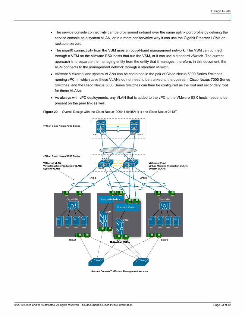
Overall Topology
Figure 20 shows the overall topology for running a VMware ESX deployment with dual 10 Gigabit Ethernet connected
servers:
● vPC is highly recommended on the access layer switches; and it interfaces with PortChannel active mode
configuration on the Cisco Nexus 1000V.
● Every VMware ESX host is configured with a system uplink port profile that also carries the VMware VMkernel
VLAN.
Design Guide
© 2010 Cisco and/or its affiliates. All rights reserved. This document is Cisco Public Information. Page 33 of 42
● The service console connectivity can be provisioned in-band over the same uplink port profile by defining the
service console as a system VLAN, or in a more conservative way it can use the Gigabit Ethernet LOMs on
rackable servers.
● The mgmt0 connectivity from the VSM uses an out-of-band management network. The VSM can connect
through a VEM on the VMware ESX hosts that run the VSM, or it can use a standard vSwitch. The current
approach is to separate the managing entity from the entity that it manages; therefore, in this document, the
VSM connects to the management network through a standard vSwitch.
● VMware VMkernel and system VLANs can be contained in the pair of Cisco Nexus 5000 Series Switches
running vPC, in which case these VLANs do not need to be trunked to the upstream Cisco Nexus 7000 Series
Switches, and the Cisco Nexus 5000 Series Switches can then be configured as the root and secondary root
for these VLANs.
● As always with vPC deployments, any VLAN that is added to the vPC to the VMware ESX hosts needs to be
present on the peer link as well.
Figure 20. Overall Design with the Cisco Nexus1000v 4.0(4)SV1(1) and Cisco Nexus 2148T

Design Guide
© 2010 Cisco and/or its affiliates. All rights reserved. This document is Cisco Public Information. Page 34 of 42
In topologies that use multiple quad Gigabit Ethernet adapters, the following recommendations apply in addition to
the previous ones:
● Create a system uplink port profile and assign at least two vmnics to the system port profile for redundancy,
with each vmnic attached to a different upstream switch.
● VMware VMkernel can be carried in-band, and potentially on the system uplink port profile.
● Divide the remaining vmnics into groups of two, in which each group has one NIC connected to one switch,
and the other NIC is connected to another switch for redundancy. Each group defines an uplink port profile.
● Depending on the capabilities of the upstream switches, you can configure each uplink port profile in channel-
group active mode (if the upstream switch supports vPC and LACP), or you can create subgroups (if the
upstream switch does not support vPC).
In all cases, the access switch ports connected to a VMware ESX host and VEM should be configured as follows:
● They should be trunks.
● The trunk should carry the virtual machine production VLANs, system VLANs, and VMware VMkernel VLAN
as needed, matching the corresponding Cisco Nexus 1000V configuration.
● The spanning-tree port type edge trunk should be enabled
Each VMware ESX host can still run a standard vSwitch to enable simple out-of-band management connectivity for
the virtual machines, which can be used for cluster heartbeats, for example, or in general low-bandwidth Layer 2
connectivity between virtual machines.
Configuration Steps
Cisco Nexus 5000 Series Configuration
This sample configuration shows the steps needed to create the vPC between the VMware ESX host running the
Cisco Nexus 1000V and the Cisco Nexus 5000 Series Switches. This configuration omits the vPC infrastructure
configuration, which should be well known to the reader (and is documented in other guides).
PortChannel 2 is a vPC connecting the 10 Gigabit Ethernet ports of the Cisco Nexus 5000 Series Switch to the two
10 Gigabit Ethernet Intel 82598 adapters on the VMware ESX host.
Replicate the following configuration identically on both Cisco Nexus 5000 Series Switches.
1. Define the port as type edge trunk, configure the port to carry the system VLANs (control and packet), and
configure the channel group for LACP (or for mode on if you prefer a static configuration):
interface Ethernet1/2
description tc-esx02
switchport mode trunk
switchport trunk allowed vlan <system vlans>, <production vlans>, <vmkernel>
untagged cos 0
spanning-tree port type edge trunk
channel-group 2 mode passive

Design Guide
© 2010 Cisco and/or its affiliates. All rights reserved. This document is Cisco Public Information. Page 35 of 42
interface port-channel2
switchport mode trunk
switchport trunk allowed vlan <system vlans>, <production vlans>, <vmkernel>
vpc 2
spanning-tree port type edge trunk
speed 10000
2. Add the system VLANs to the peer link:
int po10
switchport trunk allowed add vlan <system vlans>, <production vlans>, <vmkernel>
3. Verify that the vPC is up by entering the command show vpc brief.
If you are using Cisco NX-OS Release 4.1(3)N1 on the Cisco Nexus 5000 Series Switch and the LACP negotiation
does not complete correctly, the cause may be a problem (bug ID CSCtb84803) that was fixed in Cisco NX-OS
Release 4.1(3)N2(1). Also, if you are using first-generation CNA 10 Gigabit Ethernet cards and LACP negotiation is
not successful, you may need to disable lldp transmit on the Cisco Nexus 5000 Series 10 Gigabit Ethernet ports as
follows:
(config-if)#no lldp transmit
Configuration of the VSM
1. Make sure that the network adapters of the VSM are associated with the appropriate VLANs as shown in the
sample in the following screen:
● Control (often referred to as the AIPC interface): Network Adapter 1
● Management: Network Adapter 2 sharing the traffic with the service console and providing mgmt0 to the VSM
● Packet: Network Adapter 3

Design Guide
© 2010 Cisco and/or its affiliates. All rights reserved. This document is Cisco Public Information. Page 36 of 42
2. Network Adapter 2 uses the LOM vmnics in any of the possible NIC teaming configurations. Network Adapters 1
and 3 share the connectivity to the Cisco Nexus 5000 Series Switch (or the Cisco Nexus 2000 Series Fabric
Extender) in vPC mode. Configure NIC teaming for Network Adapters 2 and 3 as shown here:
Configure the associated interface on the Cisco Nexus 5000 Series Switch is as follows:
interface port-channel6
switchport mode trunk
switchport trunk allowed vlan 23-24
vpc 6
spanning-tree port type edge trunk
speed 10000

Design Guide
© 2010 Cisco and/or its affiliates. All rights reserved. This document is Cisco Public Information. Page 37 of 42
Configuring Redundancy
1. Create an additional VSM by using VMware vCenter Converter with the Cisco Nexus 1000V Open Virtualization
Format (OVF) or Open Virtualization Format Archive (OVA) file as shown here:
2. When the VSM comes up, follow this procedure:
a) Make the VSM standalone.
b) Configure packet and control VLANs and the domain ID.
c) Assign a management IP address to mgmt0 and assign mgmt0 to virtual route forwarding (VRF)
management.
d) Assign a default route to VRF context management.
e) Verify that the VSM can communicate over the management network.
f) Change the role to secondary.
g) Verify that the network adapters of the redundant VSM are connected to the correct port groups
h) Reload the VSM
The two VSMs should form an active-standby relationship.
Initial VSM and Cisco Nexus 1000V Configuration
1. Enter the following command to see the license information:
tc-nexus1kv04# show license host-id
2. Use the product authorization key (PAK) and the host ID to request a license from
http://www.cisco.com/go/license/
install license bootflash:<licence file>
svs-domain
domain id 1

Design Guide
© 2010 Cisco and/or its affiliates. All rights reserved. This document is Cisco Public Information. Page 38 of 42
control vlan 23
packet vlan 24
svs mode L2
3. Make sure that the network adapters on the VSM are correctly assigned and that teaming is correctly configured.
Give the VSM a mgmt0 IP address:
vrf context management
ip route 0.0.0.0/0 10.51.35.97
interface mgmt0
vrf member management
ip address 10.51.35.114/27
4. For the VSM to talk to VMware vCenter, VMware vCenter needs information about the VSM credentials, so
import the XML plug-in (extension.xml, which includes the keys needed to establish an SSL channel between the
VSM and VMware vCenter). Each individual VSM needs its own extension.xml file (and associated extension
key) for it to communicate with VMware vCenter. You can download the extension.xml from
http://{VSM_IP_ADDR}/cisco_nexus_1000v_extension.xml.
5. To check the extension key from the Cisco Nexus 1000V VSM, enter the following command:
show vmware vc extension-key
6. Add the plug-in as shown here:

Design Guide
© 2010 Cisco and/or its affiliates. All rights reserved. This document is Cisco Public Information. Page 39 of 42
7. Register the plug-in as shown here:
8. Establish connectivity between the VSM and vCenter as follows
svs connection VC
protocol vmware-vim
vmware dvs <datacenter name>
remote ip address 10.51.35.115 (ip address of vCenter server)
connect
Configuring the System Port Profile
1. Configure the system VLANs:
vlan 23
vlan 24
2. Configure the system uplink port profiles:
port-profile system-uplink
capability uplink
vmware port-group fabric_uplinks
switchport mode trunk
switchport trunk allowed vlan 23-24
channel-group auto mode active
no shutdown
system vlan 23-24
state enabled

Design Guide
© 2010 Cisco and/or its affiliates. All rights reserved. This document is Cisco Public Information. Page 40 of 42
3. Configure the Cisco Nexus 5000 and 2000 Series ports to carry the system VLANs as follows:
interface Ethernet <Nexus 5k or 2k interface connected to ESX host>
description n5k-intf-to-esx
switchport mode trunk
switchport trunk allowed vlan add 23,24
spanning-tree port type edge trunk
4. When the interfaces are configured for vPC, configure the PortChannel interface on both Cisco Nexus 5000
Series Switches.
Adding VMware ESX Hosts to the Cisco Nexus 1000V
1. Make sure that you have installed the VEM component on the VMware ESX host either by using VMware Update
Manager or by manually copying the vib file (which you can download with your browser from the VSM):
esxupdate -b ./cross_cisco-vem-v100-4.0.4.1.1.27-0.4.2-release.vib update
2. Add hosts to the Cisco Nexus 1000V from VMware vCenter as needed by right-clicking the vDS icon of the Cisco
Nexus1000V (labeld tc-n1kv04 or tc-nexus1kv04) shown here (make sure the Cisco Nexus 1000V is selected):

Design Guide
© 2010 Cisco and/or its affiliates. All rights reserved. This document is Cisco Public Information. Page 41 of 42
3. Select the correct uplink port profile from the distributed virtual uplink port group tab as shown here:
Configuring Uplink Port Profiles
1. Configure the production VLANs:
vlan 50
vlan 60
2. Configure the uplink port profiles by adding them to an existing system uplink port profile:
port-profile system-uplink
switchport trunk allowed vlan add 50,60
3. You can also configure additional uplink port profiles all together and reassign physical interfaces as needed:
port-profile web-traffic-uplink
capability uplink
vmware port-group web-traffic
switchport mode trunk
switchport trunk allowed vlan 50,60
channel-group auto mode active
no shutdown
state enabled

Design Guide
© 2010 Cisco and/or its affiliates. All rights reserved. This document is Cisco Public Information. Page 42 of 42
4. Reassign the physical NICs to the newly defined uplink port profile from VMware vCenter by selecting the
VMware ESX host, selecting the Configuration tab and then Manage Physical Adapters. Here, you can
remove a vmnic from an uplink port profile and move it to a different one, or you can add a vmnic to an uplink
port profile as shown here:
5. If the upstream switches do not support PortChannels, you can change the port profile configuration as follows:
port-profile web-traffic-uplink
capability uplink
vmware port-group web-traffic
switchport mode trunk
switchport trunk allowed vlan 50,60
channel-group auto mode on sub-group cdp
no shutdown
state enabled
6. Define the subgroups by entering the command sub-group [0 | 1 ] on a per-interface basis.
Printed in USA C07-572832-00 02/10