Embed Size (px)
Citation preview

Data Acquisition
Risanuri Hidayat

PC-based Data AcquisitionSystem Overview
In the last few years, industrial PC I/O interface products have become increasingly reliable, ccurate and affordable. PC-based data acquisition and control systems are widely used in industrial and laboratory applications like monitoring, control, data acquisition and automated testing.Selecting and building a DA&C (Data Acquisition and Control) system that actually does what you want it to do requires some knowledge of electrical and computer engineering.
• Transducers and actuators • Signal conditioning • Data acquisition and control hardware • Computer systems software

Data Acquisition System Introduction I
A data acquisition system consists of many components that are integrated to:Sense physical variables (use of transducers)Condition the electrical signal to make it readable by an A/D board

Data Acquisition System Introduction II
Convert the signal into a digital format acceptable by a computerProcess, analyze, store, and display the acquired data with the help of software

Data Acquisition SystemBlock Diagram

Transducers Sense physical phenomena and
translate it into electric signal.
Displacement Level Electric signals ON/OFF switch
Temperature Pressure Light Force

Transducers and Actuators
A transducer converts temperature, pressure, level, length, position, etc. into voltage, current, frequency, pulses or other signals.An actuator is a device that activates process control equipment by using pneumatic, hydraulic or electrical power. For example, a valve actuator opens and closes a valve to control fluid rate.

Signal ConditioningSignal conditioning circuits improve the quality of signals generated by transducers before they are converted into digital signals by the PC's data-acquisition hardware. Examples of signal conditioning are signal scaling, amplification, linearization, cold-junction compensation, filtering, attenuation, excitation, common-mode rejection, and so on.

Signal ConditioningOne of the most common signal conditioning functions is amplification.For maximum resolution, the voltage range of the input signals should be approximately equal to the maximum input range of the A/D converter. Amplification expands the range of the transducer signals so that they match the input range of the A/D converter. For example, a x10 amplifier maps transducer signals which range from 0 to 1 V into the range 0 to 10 V before they go into the A/D converter.

Signal Conditioning Electrical signals are conditioned
so they can be used by an analog input board. The following features may be available:
Amplification Isolation
FilteringLinearization

Data AcquisitionData acquisition and control hardware generally performs one or more of the following functions: analog input, analog output, digital input, digital output and counter/timer functions.

Analog Inputs (A/D)Analog to digital (A/D) conversion changes analog voltage or current levels into digital information. The conversion is necessary to enable the computer to process or store the signals.

Analog Inputs (A/D)The most significant criteria when selecting A/D hardware are: 1. Number of input channels 2. Single-ended or differential input signals 3. Sampling rate (in samples per second) 4. Resolution (usually measured in bits of
resolution) 5. Input range (specified in full-scale volts) 6. Noise and nonlinearity

Analog to Digital (A/D) Converter
Input signalSampling rateThroughput
Resolution Range Gain

A/D Converter: Input Signal
Analog Signal is continuous Example: strain gage. Most of
transducers produce analog signals Digital
Signal is either ON or OFF Example: light switch.

A/D Converter:Sampling Rate
Determines how often conversions take place.
The higher the sampling rate, the better.
Analog Input 4 Samples/cycle8 Samples/cycle16 Samples/cycle

A/D Converter:Sampling Rate
Aliasing. Acquired signal gets distorted if
sampling rate is too small.

A/D Converter:Throughput
Effective rate of each individual channel is inversely proportional to the number of channels sampled.
Example: 100 KHz maximum. 16 channels.
100 KHz/16 = 6.25 KHz per channel.

A/D Converter:Range
Minimum and maximum voltage levels that the A/D converter can quantize
Ranges are selectable (either hardware or software) to accurately measure the signal

A/D Converter: Resolution

Analog Outputs (D/A)The opposite of analog to digital conversion is digital to analog (D/A) conversion. This operation converts digital information into analog voltage or current. D/A devices allow the computer to control real-world events.Analog output signals may directly control process equipment. The process can give feedback in the form of analog input signals. This is referred to as a closed loop control system with PID control. Analog outputs can also be used to generate waveforms. In this case, the device behaves as a function generator.

Analog Outputs (D/A)

Data Acquisition Software It can be the most critical factor in obtaining reliable, high performance operation.Transforms the PC and DAQ hardware into a complete DAQ, analysis, and display system.Different alternatives:
Programmable software. Data acquisition software packages.

Programmable SoftwareInvolves the use of a programming language, such as: C++, visual C++ BASIC, Visual Basic + Add-on tools (such as
VisuaLab with VTX) Fortran Pascal
Advantage: flexibilityDisadvantages: complexity and steep
learning curve

Data Acquisition Software
Does not require programming.Enables developers to design the custom instrument best suited to their application.Examples: TestPoint, SnapMaster, LabView, DADISP, DASYLAB, etc.
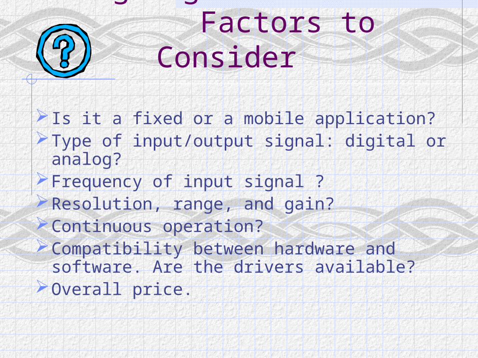
Designing a DAS: Factors to Consider
Is it a fixed or a mobile application?Type of input/output signal: digital or analog?Frequency of input signal ?Resolution, range, and gain?Continuous operation?Compatibility between hardware and
software. Are the drivers available?Overall price.