Embed Size (px)
Citation preview

Dashboard user manual rev2e
- 1 -
User manual
Dashboard for Windows V1.3.x
Waarderveldweg 3 2031 BK Haarlem The Netherlands
Tel +31 23 5149900 Fax +31 23 5322583 Email: [email protected]
Dashboard user manual rev2e
- 2 -
TABLE OF CONTENTS
1 INTRODUCTION ............................................................................................................ 4
2 INSTALLING DASHBOARD ........................................................................................... 5
2.1 Getting started with the Dashboard software ........................................................... 5
3 EXPLAINING THE DASHBOARD ENVIRONMENT ....................................................... 6
3.1 The Menu bar .......................................................................................................... 6 3.1.1 Menu bar – File .................................................................................................... 7 3.1.2 Menu bar – View .................................................................................................. 7 3.1.3 Menu bar – ‘Device name’ (e.g. ‘e-xpert pro’ or ‘OC12-60’) ................................. 7 3.1.4 Menu bar – Tools ................................................................................................. 9 3.1.5 Menu bar – Window ............................................................................................. 9 3.1.6 Menu bar – Help .................................................................................................. 9
4 BATTERY MONITOR CONTROL ..................................................................................10
4.1 Battery monitor display panel .................................................................................10 4.2 Battery monitor status ............................................................................................10 4.3 Battery monitor history ...........................................................................................11
4.3.1 The Battery tab ...................................................................................................12 4.3.2 The Alarms tab ...................................................................................................13
4.4 Battery monitor setup .............................................................................................14 4.4.1 The General tab ..................................................................................................14 4.4.2 The Main Battery Alarms tab ..............................................................................15 4.4.3 The Aux. Battery Alarms tab ...............................................................................17 4.4.4 The Battery tab ...................................................................................................18 4.4.5 The Monitor Display tab ......................................................................................19 4.4.6 The Monitor Processing tab ................................................................................20
5 OMNICHARGE CONTROL ...........................................................................................23
5.1 Omnicharge display panel ......................................................................................23 5.2 Omnicharge setup ..................................................................................................23
5.2.1 The General tab ..................................................................................................23 5.2.2 The Alarms tab ...................................................................................................24
6 POWERSINE COMBI CONTROL .................................................................................27
6.1 Powersine Combi display panel .............................................................................27 6.2 Powersine Combi setup .........................................................................................28
6.2.1 The General tab ..................................................................................................28 6.2.2 The Inverter tab ..................................................................................................29 6.2.3 The Charger tab .................................................................................................31 6.2.4 The Transfer Switch tab ......................................................................................33
7 POWERSINE CONTROL ..............................................................................................36
7.1 Powersine display panel .........................................................................................36
8 CHARGE PROGRAM EDITOR .....................................................................................37
8.1 The General tab .....................................................................................................37 8.2 The Soft Start tab ...................................................................................................39 8.3 The Bulk tab ...........................................................................................................41 8.4 The Ext. Bulk tab ....................................................................................................43

Dashboard user manual rev2e
- 3 -
8.5 The Absorption tab .................................................................................................45 8.6 The Analyze tab .....................................................................................................47 8.7 The Float tab ..........................................................................................................49 8.8 The Pulse tab .........................................................................................................50 8.9 The Equalize tab ....................................................................................................52 8.10 The Stop tab ..........................................................................................................54 8.11 The Error tab ..........................................................................................................56
9 END USER LICENSE AGREEMENT ............................................................................58
Dashboard user manual rev2e
- 4 -
1 INTRODUCTION
Thank you for using Dashboard for Windows. Dashboard is a comprehensive software platform, intended for configuration and readout of TBSLink enabled products from TBS Electronics. It also offers a data logging feature capable of logging all available parameters from your TBS product, for further analysis in for example Microsoft Excel. Dashboard shall evolve continuously with the addition of new features and support for future products.
Currently, the following TBS products are supported:
- e-xpert pro(-hv) and e-xpert 501 battery monitors - Omnicharge OC20-60 programmable automatic battery chargers - Powersine Combi PSC1600-PSC1800 professional inverter-charger series - Powersine PS1000-PS1800 professional inverter series
These TBS products must be connected to your Windows PC by either a USB or RS232 Communication kit (e-xpert series), or a USB to TBSLink Communication kit (Powersine, Powersine Combi and Omnicharge series).

Dashboard user manual rev2e
- 5 -
2 INSTALLING DASHBOARD
For information on the physical connections between the TBS product, the interface box and the PC, please consult the installation guides that are supplied along with all TBS products.
If you connect to your PC using USB, please make sure that you only connect the USB cable to your PC after Dashboard is completely installed.
Dashboard for Windows is compatible with Windows XP, Windows Vista and Windows 7. Please follow the steps below to ensure proper installation of the Dashboard communication software on your PC:
1) Exit all running Windows programs.
2) Run Setup.exe from the USB flash drive or CD-ROM that came with your Communication Kit or download the latest version of Dashboard, extract the .zip file and run Setup.exe.
3) Follow the step-by-step instructions on your screen to complete the software installation. NOTE: When you are not logged on with administrator privileges, Windows may ask you for an administrator password a few times.
4) During installation, you may be asked to acknowledge installation of USB drivers twice.
5) After the software installation is completed, you can connect the USB interface box to a free USB port on your PC.
2.1 Getting started with the Dashboard software
To start the Dashboard communication software after installing, proceed with the following steps:
1) Click on the Windows [START] button.
2) Select [PROGRAMS] followed by [Dashboard].
3) Choose the Dashboard icon to launch the software. When your device is connected to the PC, a corresponding icon will appear in the Device manager.
Dashboard user manual rev2e
- 6 -
3 EXPLAINING THE DASHBOARD ENVIRONMENT
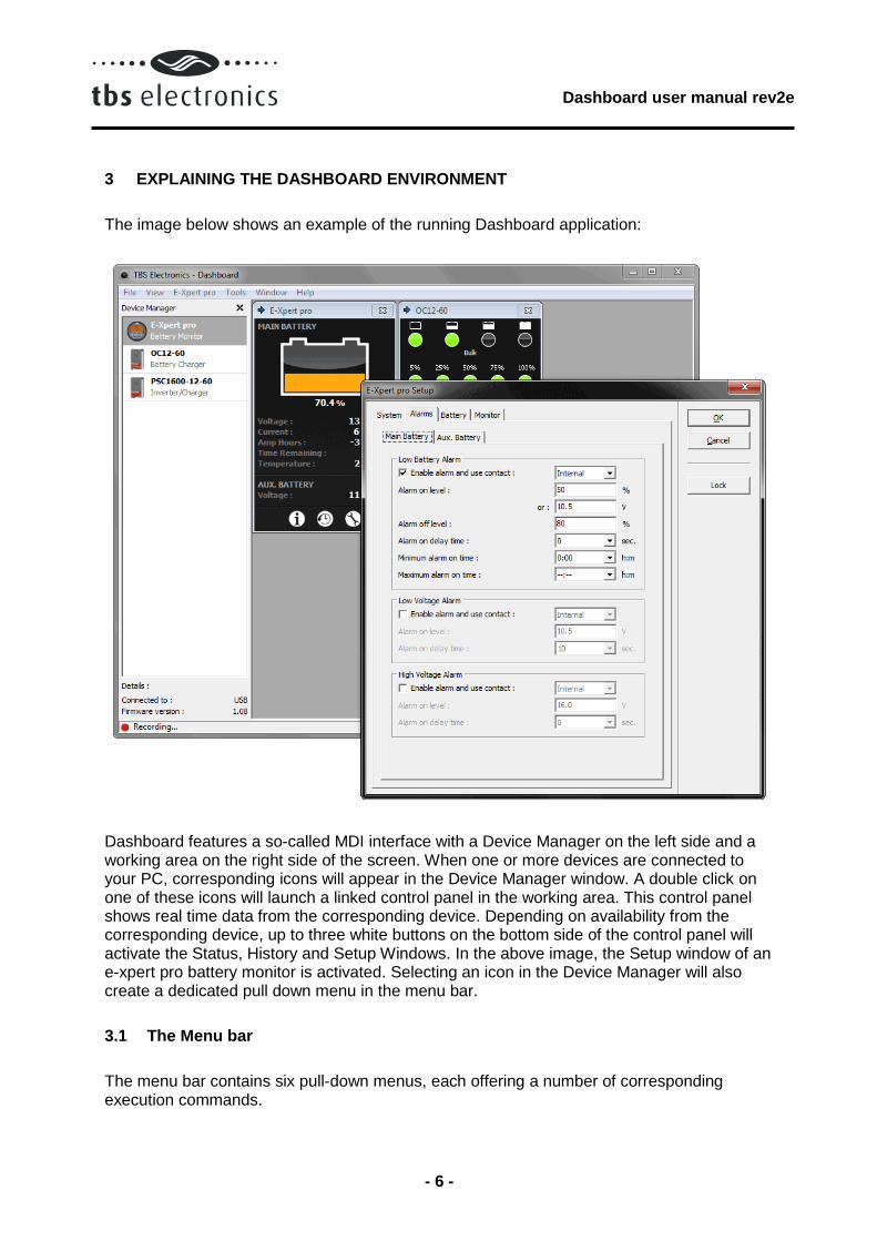
The image below shows an example of the running Dashboard application:
Dashboard features a so-called MDI interface with a Device Manager on the left side and a working area on the right side of the screen. When one or more devices are connected to your PC, corresponding icons will appear in the Device Manager window. A double click on one of these icons will launch a linked control panel in the working area. This control panel shows real time data from the corresponding device. Depending on availability from the corresponding device, up to three white buttons on the bottom side of the control panel will activate the Status, History and Setup Windows. In the above image, the Setup window of an e-xpert pro battery monitor is activated. Selecting an icon in the Device Manager will also create a dedicated pull down menu in the menu bar.
3.1 The Menu bar
The menu bar contains six pull-down menus, each offering a number of corresponding execution commands.

Dashboard user manual rev2e
- 7 -
3.1.1 Menu bar – File
<New Recording...>
Runs the recording wizard to start logging parameter data of your preferred device. Follow the wizard instructions on your screen to setup the recording. During recording a small three button control panel will appear in the working area. This panel will enable you to stop, pause or restart your recording.
<Exit>
Closes the Dashboard application.
3.1.2 Menu bar – View
<Device Manager>
Check or uncheck the Device Manager to enable or disable its appearance on the left side of the screen.
<Status Bar>
Check or uncheck the Status Bar to enable or disable its appearance on the bottom of the screen.
3.1.3 Menu bar – ‘Device name’ (e.g. ‘e-xpert pro’ or ‘OC12-60’)
Since the name of this pull-down menu is depending on the type of TBS product selected in the Device Manager, the contents of this menu will also automatically adapt to this. Currently, four TBS product types are supported in Dashboard and each corresponding device name menu will be explained below:
e-xpert (e-xpert pro or e-xpert 501)
<Show Panel>
Launch the control panel in the working area.
<Status...>
Launch the selected device’s Status Window.
<History...>
Launch the selected device’s History Window.
<Setup...>
Launch the selected device’s Setup Window.
<Rename...>

Dashboard user manual rev2e
- 8 -
Rename the selected device.
<Make Report...>
Create and save a text file that lists all status, history and setup data of the selected device.
Omnicharge (e.g. OC12-60 or OC24-30)
<Show Panel>
Launch the control panel in the working area.
<Setup...>
Launch the selected device’s Setup Window.
<Rename...>
Rename the selected device.
<Make Report...>
Create and save a text file that lists all status and setup data of the selected device.
Powersine Combi (e.g. PSC1600-12-60 or PSC1800-24-35)
<Show Panel>
Launch the control panel in the working area.
<Setup...>
Launch the selected device’s Setup Window.
<Rename...>
Rename the selected device.
<Make Report...>
Create and save a text file that lists all status and setup data of the selected device.
<Update Firmware...>
Update the firmware of the selected device. A wizard will guide you through the update process. A firmware file must be supplied by TBS Electronics.
Inverter (e.g. PS1600-12 or PS1800-24)
<Show Panel>
Launch the control panel in the working area.
<Rename...>

Dashboard user manual rev2e
- 9 -
Rename the selected device.
<Make Report...>
Create and save a text file that lists all status and setup data of the selected device.
3.1.4 Menu bar – Tools
<Charge Program Editor…>
Launch the charge program editor wizard to create or modify Omnicharge and/or Powersine Combi charge programs (see chapter 5.3 for further explanation). Charge program files are interchangeable between all devices capable of charging.
3.1.5 Menu bar – Window
<Cascade>
Cascades all control panels in the working area.
<Tile>
Tile all control panels in the working area.
<Arrange All>
Arrange all control panels in the working area.
3.1.6 Menu bar – Help
<View “User manual”>
Open this user manual (A PDF reader like Adobe Acrobat or Foxit Reader needs to be installed on your system).
<About>
Shows Dashboard version.
Dashboard user manual rev2e
- 10 -
4 BATTERY MONITOR CONTROL
Dashboard allows display, setup and readout of all available parameters of the e-xpert pro, e-xpert pro-hv and e-xpert 501 battery monitors.
4.1 Battery monitor display panel
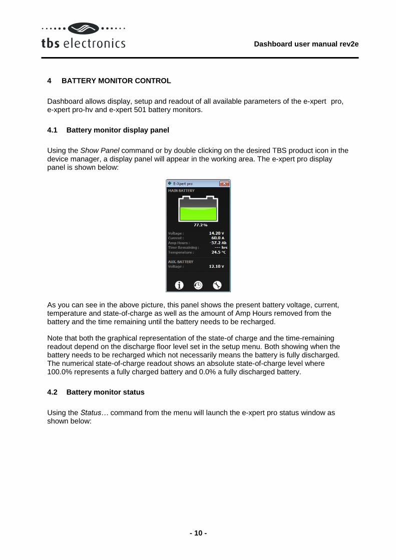
Using the Show Panel command or by double clicking on the desired TBS product icon in the device manager, a display panel will appear in the working area. The e-xpert pro display panel is shown below:
As you can see in the above picture, this panel shows the present battery voltage, current, temperature and state-of-charge as well as the amount of Amp Hours removed from the battery and the time remaining until the battery needs to be recharged.
Note that both the graphical representation of the state-of charge and the time-remaining readout depend on the discharge floor level set in the setup menu. Both showing when the battery needs to be recharged which not necessarily means the battery is fully discharged. The numerical state-of-charge readout shows an absolute state-of-charge level where 100.0% represents a fully charged battery and 0.0% a fully discharged battery.
4.2 Battery monitor status
Using the Status… command from the menu will launch the e-xpert pro status window as shown below:

Dashboard user manual rev2e
- 11 -
The Status window shows the following parameters:
Status group
<Days running>
The number of days the battery monitor is operating to monitor your battery. This item resets when a battery reset is executed.
<Days since synchronized>
The number of days the battery monitor has not been synchronized. This item resets when the battery monitor is synchronized or when a battery reset is executed.
<Charge Efficiency Factor>
The charge efficiency factor (CEF) used by the battery monitor. Depending on the value set in the setup menu, this item displays the automatically calculated CEF or the manually set CEF.
Alarms group
Shows the alarms that are currently active.
4.3 Battery monitor history
Using the History… command from the menu will launch the e-xpert pro history window.

Dashboard user manual rev2e
- 12 -
4.3.1 The Battery tab
The e-xpert pro history window will open on the Battery tab as shown below:
Discharge group
<Average discharge (Ah)>
The average amount of Amp Hours removed from the battery per cycle. This number will be recalculated after each synchronization.
<Average discharge (%)>
The average discharge depth in % state-of-charge. This number will be recalculated after each synchronization.
<Deepest discharge (Ah)>
The deepest discharge that occurred in Amp Hours.
<Deepest discharge (%)>
The deepest discharge that occurred in % state-of-charge.
Total Amp Hours group
<Total Amp Hours removed>
The total number of Amp Hours removed from the battery.

Dashboard user manual rev2e
- 13 -
<Total Amp Hours charged>
The total number of Amp Hours charged to the battery. These Amp Hours are not compensated by the Charge Efficiency Factor (CEF).
Cycles group
<Cycles>
The number of full cycles.
<Synchronizations>
The number of synchronizations that have occurred.
<Full discharges>
The number of times the battery has been fully discharged reaching a state-of-charge of 0.0%.
4.3.2 The Alarms tab
The Alarms tab of the History window is shown below:
Alarms group
<Low Battery alarms>
The number of Low Battery alarms.

Dashboard user manual rev2e
- 14 -
<Main battery low voltage alarms>
The number of Main battery low voltage alarms.
<Auxiliary battery low voltage alarms>
The number of Auxiliary battery low voltage alarms.
<Main battery high voltage alarms>
The number of Main battery high voltage alarms.
<Auxiliary battery high voltage alarms>
The number of Auxiliary battery high voltage alarms.
4.4 Battery monitor setup
Using the Setup… command will launch the e-xpert pro setup window.
4.4.1 The General tab
The e-xpert pro setup window will open on the System tab as shown below:
The System tab of the setup window allows the following settings:
Auto-sync group
Dashboard user manual rev2e
- 15 -
<Charger’s float voltage>
This value must be equal to your battery charger’s float voltage. which is the last stage of the charging process. In this stage the battery is considered full.
<Charger’s float current>
When the charge current is below this percentage of the battery capacity the battery is considered fully charged. Make sure this value is always greater than the minimum current at which the charger maintains the battery or stops charging.
<Auto-sync time>
The time the auto-sync voltage and current above must be met in order to consider the battery as fully charged.
<Auto-sync sensitivity>
Only change this setting when the above parameters are set correctly and automatic synchronization still fails. If automatic synchronization takes too long or does never occur, lower this value. When the battery monitor synchronizes too early, increase this value.
Discharge Floor group
<Level>
The reference point at which the battery needs to be recharged. When the state-of-charge percentage falls below this value the Charge Battery indicator starts flashing while the time remaining readout shows 0:00 and the state-of-charge bar is empty.
Battery Temperature group
Choose to either measure the battery temperature using the optional temperature sensor or set the battery temperature manually.
Time Remaining group
<Averaging filter>
Specifies the time window of the moving averaging filter. There are three settings, where setting 0 gives the fastest Time remaining readout response and setting 2 the slowest. The best setting will depend on the type of battery load and your personal preference.
4.4.2 The Main Battery Alarms tab
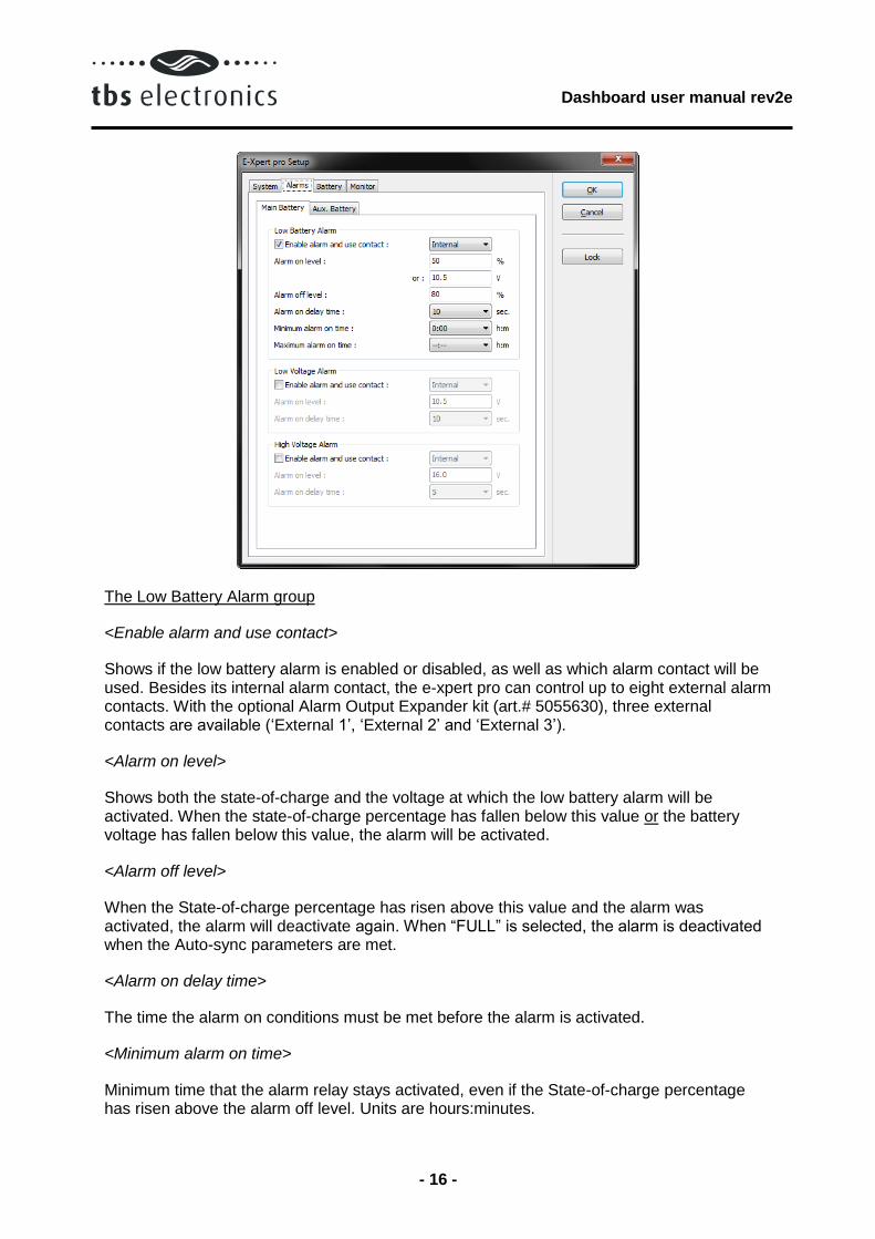
The Main Battery tab on the Alarms tab of the Setup window is shown below:
Dashboard user manual rev2e
- 16 -
The Low Battery Alarm group
<Enable alarm and use contact>
Shows if the low battery alarm is enabled or disabled, as well as which alarm contact will be used. Besides its internal alarm contact, the e-xpert pro can control up to eight external alarm contacts. With the optional Alarm Output Expander kit (art.# 5055630), three external contacts are available (‘External 1’, ‘External 2’ and ‘External 3’).
<Alarm on level>
Shows both the state-of-charge and the voltage at which the low battery alarm will be activated. When the state-of-charge percentage has fallen below this value or the battery voltage has fallen below this value, the alarm will be activated.
<Alarm off level>
When the State-of-charge percentage has risen above this value and the alarm was activated, the alarm will deactivate again. When “FULL” is selected, the alarm is deactivated when the Auto-sync parameters are met.
<Alarm on delay time>
The time the alarm on conditions must be met before the alarm is activated.
<Minimum alarm on time>
Minimum time that the alarm relay stays activated, even if the State-of-charge percentage has risen above the alarm off level. Units are hours:minutes.

Dashboard user manual rev2e
- 17 -
<Maximum alarm on time>
Maximum time that the alarm stays activated even if the state-of-charge percentage is still below the alarm off value. The value “-:--“ indicates infinite at which the relay will stay activated until the state-of-charge has risen above the alarm off level. Units are hours:minutes
The Low- and High Voltage Alarm groups
<Enable alarm and use contact>
Shows if the low- or high voltage alarm is enabled or disabled, as well as which alarm contact will be used. Besides its internal alarm contact, the e-xpert pro can control up to eight external alarm contacts. With the optional Alarm Output Expander kit (art.# 5055630), three external contacts are available (‘External 1’, ‘External 2’ and ‘External 3’).
<Alarm on level>
Shows the voltage at which the low- or high voltage alarm will be activated. Both the low- and high voltage alarms have a hysteresis of 0.1V
<Alarm on delay time>
The time the alarm on conditions must be met before the alarm is activated.
4.4.3 The Aux. Battery Alarms tab
The Aux. Battery tab on the Alarms tab of the Setup window is shown below:
Dashboard user manual rev2e
- 18 -
The Low- and High Voltage Alarm groups
<Enable alarm and use contact>
Shows if the low- or high voltage alarm is enabled or disabled, as well as which alarm contact will be used. Besides its internal alarm contact, the e-xpert pro can control up to eight external alarm contacts. With the optional Alarm Output Expander kit (art.# 5055630), three external contacts are available (‘External 1’, ‘External 2’ and ‘External 3’).
<Alarm on level>
Shows the voltage at which the low- or high voltage alarm will be activated. Both the low- and high voltage alarms have a hysteresis of 0.1V
<Alarm on delay time>
The time the alarm on conditions must be met before the alarm is activated.
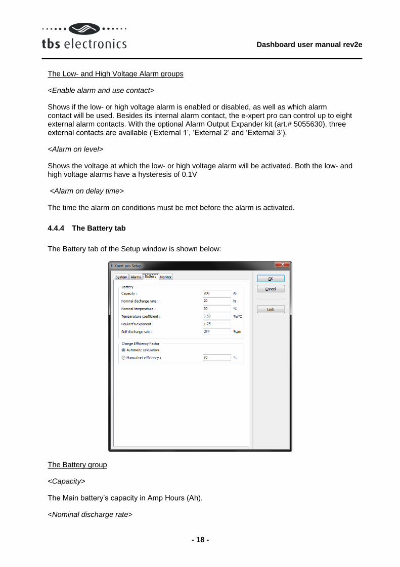
4.4.4 The Battery tab
The Battery tab of the Setup window is shown below:
The Battery group
<Capacity>
The Main battery’s capacity in Amp Hours (Ah).
<Nominal discharge rate>

Dashboard user manual rev2e
- 19 -
The discharge rate (C-rating in hours) at which the battery manufacturer rates your battery’s capacity.
<Nominal temperature>
The temperature at which the battery manufacturer rates your battery’s capacity.
<Temperature coefficient>
The percentage that your battery’s capacity changes with temperature. The unit of this value is percent capacity per degree Celsius. The setting “OFF” disables temperature compensation.
<Peukert’s exponent>
The Peukert’s exponent represents the effect of reducing battery capacity at higher discharge rates. When the Peukert value of your battery is unknown, it is recommended to keep this value at 1.25. A value of 1.00 disables the Peukert compensation.
<Self-discharge rate>
This is the rate at which the battery loses capacity by itself, even when it is not used. The unit of this value is percent capacity per month at the nominal temperature. The setting “OFF” disables self-discharge compensation.
Charge Efficiency Factor group
Choose to either let the battery monitor calculate the Charge Efficiency Factor or set the Charge Efficiency Factor manually.
4.4.5 The Monitor Display tab
The Display tab on the Monitor tab of the Setup window is shown below:

Dashboard user manual rev2e
- 20 -
The Backlight group
Choose how the backlight behaves.
The Temperature Readout Units group
Select how you want to display the battery temperature. In °C or °F.
The Readout Parameters group
Choose which parameters you want to show on the battery monitor itself when in normal operating mode. Dashboard will always show all parameters regardless of this setting.
4.4.6 The Monitor Processing tab
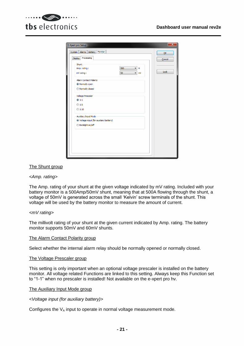
The Processing tab on the Monitor tab of the Setup window is shown below:
Dashboard user manual rev2e
- 21 -
The Shunt group
<Amp. rating>
The Amp. rating of your shunt at the given voltage indicated by mV rating. Included with your battery monitor is a 500Amp/50mV shunt, meaning that at 500A flowing through the shunt, a voltage of 50mV is generated across the small ‘Kelvin’ screw terminals of the shunt. This voltage will be used by the battery monitor to measure the amount of current.
<mV rating>
The millivolt rating of your shunt at the given current indicated by Amp. rating. The battery monitor supports 50mV and 60mV shunts.
The Alarm Contact Polarity group
Select whether the internal alarm relay should be normally opened or normally closed.
The Voltage Prescaler group
This setting is only important when an optional voltage prescaler is installed on the battery monitor. All voltage related Functions are linked to this setting. Always keep this Function set to “1-1” when no prescaler is installed! Not available on the e-xpert pro hv.
The Auxiliary Input Mode group
<Voltage input (for auxiliary battery)>
Configures the VA input to operate in normal voltage measurement mode.

Dashboard user manual rev2e
- 22 -
<Backlight on/off>
Configures the VA input to control the backlight. In this mode, the backlight is switched ON at an input voltage higher than 2V and switched OFF if the voltage is below 1V.
The Communication group
<Request mode>
When enabled, the battery monitor only sends data when requested. When disabled the battery monitor broadcasts data.
<E-Xpert 501 compatibility mode>
When enabled the e-xpert pro sends parameter data in the same format as the E-Xpert 501.
Dashboard user manual rev2e
- 23 -
5 OMNICHARGE CONTROL
Dashboard allows display, setup and readout of all available parameters of your Omnicharge battery charger. Additionally, Dashboard allows you to create new or modify existing charge programs using the Charge Program Editor. This way the Omnicharge can be adapted to all types of batteries.
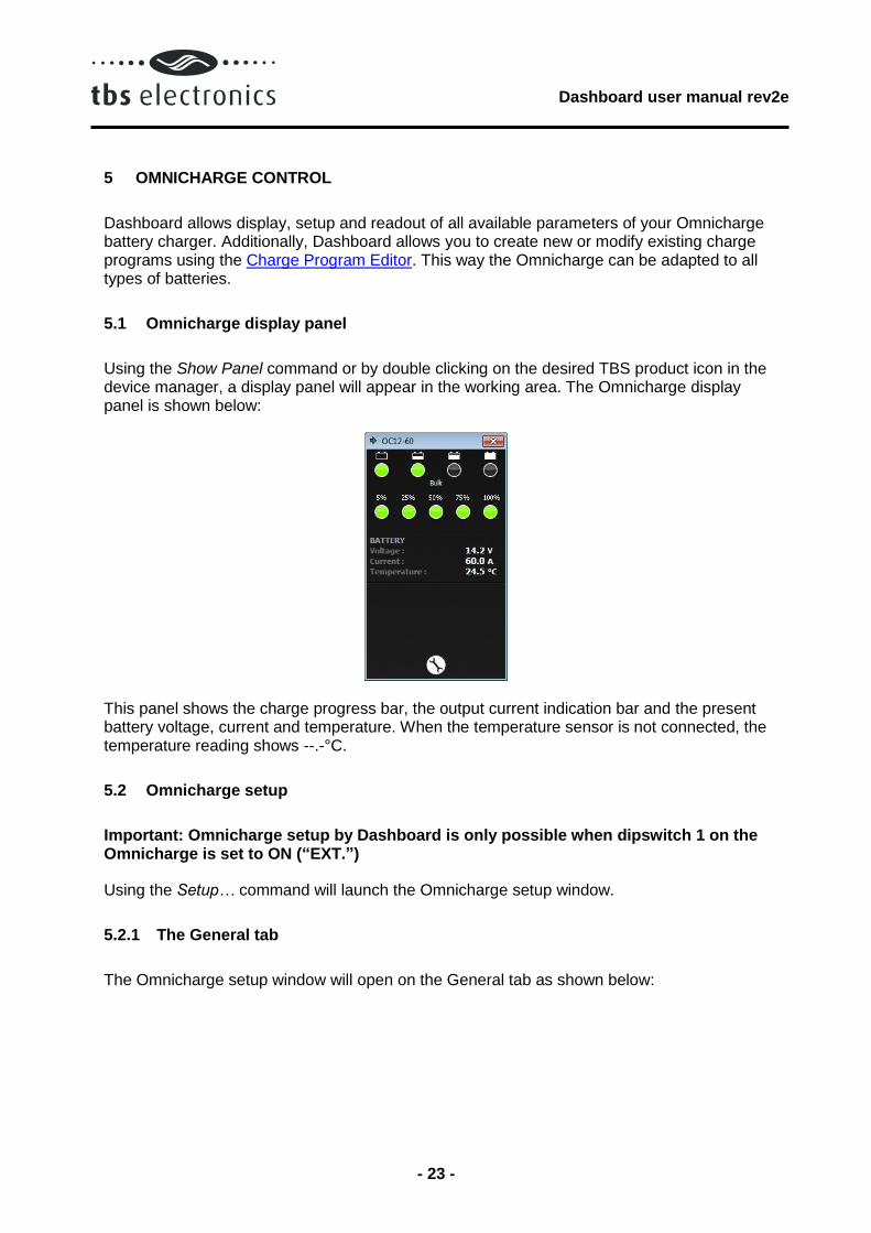
5.1 Omnicharge display panel
Using the Show Panel command or by double clicking on the desired TBS product icon in the device manager, a display panel will appear in the working area. The Omnicharge display panel is shown below:
This panel shows the charge progress bar, the output current indication bar and the present battery voltage, current and temperature. When the temperature sensor is not connected, the temperature reading shows --.-°C.
5.2 Omnicharge setup
Important: Omnicharge setup by Dashboard is only possible when dipswitch 1 on the Omnicharge is set to ON (“EXT.”)
Using the Setup… command will launch the Omnicharge setup window.
5.2.1 The General tab
The Omnicharge setup window will open on the General tab as shown below:
Dashboard user manual rev2e
- 24 -
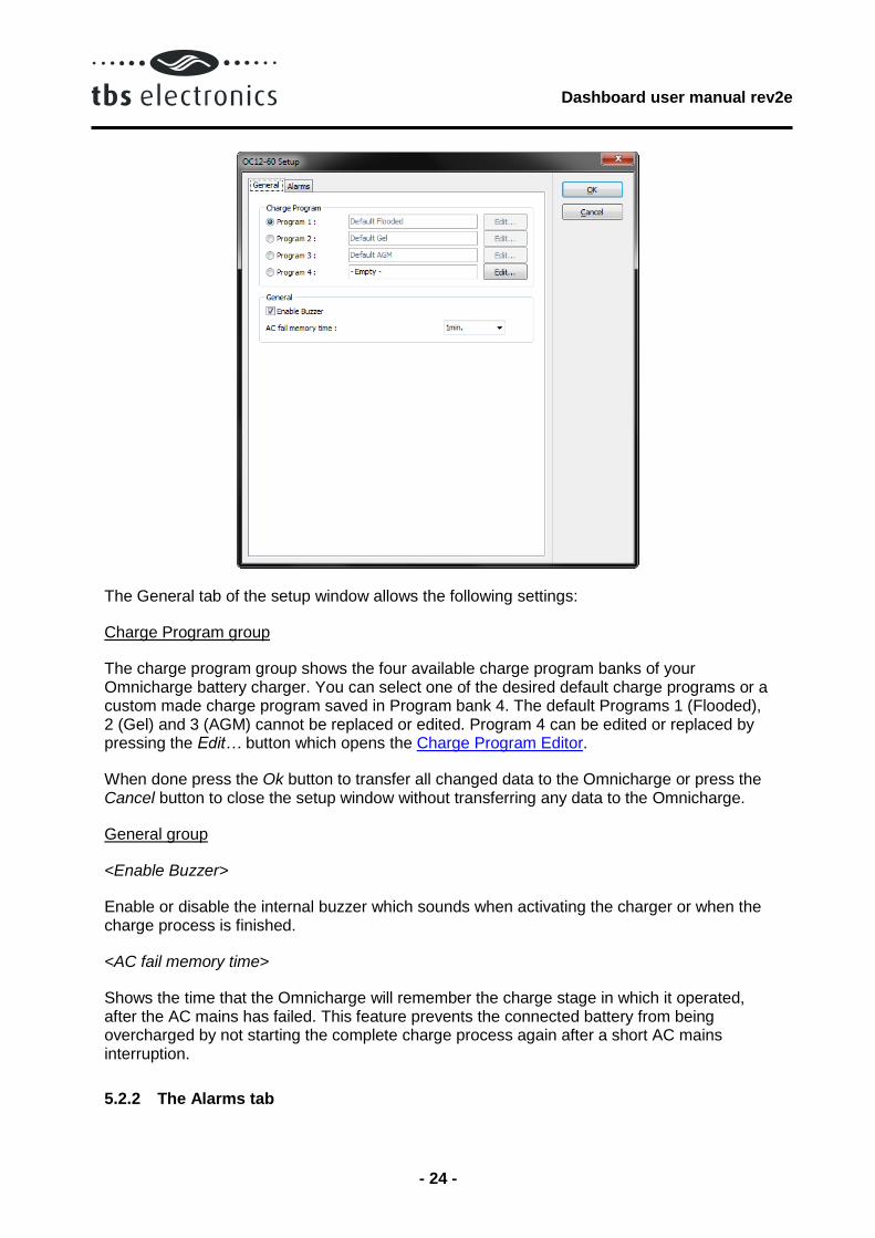
The General tab of the setup window allows the following settings:
Charge Program group
The charge program group shows the four available charge program banks of your Omnicharge battery charger. You can select one of the desired default charge programs or a custom made charge program saved in Program bank 4. The default Programs 1 (Flooded), 2 (Gel) and 3 (AGM) cannot be replaced or edited. Program 4 can be edited or replaced by pressing the Edit… button which opens the Charge Program Editor.
When done press the Ok button to transfer all changed data to the Omnicharge or press the Cancel button to close the setup window without transferring any data to the Omnicharge.
General group
<Enable Buzzer>
Enable or disable the internal buzzer which sounds when activating the charger or when the charge process is finished.
<AC fail memory time>
Shows the time that the Omnicharge will remember the charge stage in which it operated, after the AC mains has failed. This feature prevents the connected battery from being overcharged by not starting the complete charge process again after a short AC mains interruption.
5.2.2 The Alarms tab

Dashboard user manual rev2e
- 25 -
The Alarms tab of the Setup window is shown below:
The following options and parameters can be edited:
Low Voltage Alarm group
<Enable alarm and use contact>
Shows if the battery low voltage alarm is enabled or disabled, as well as which alarm contact will be activated. Please note that the Omnicharge battery chargers will not charge batteries with a voltage lower than 1V/cell (6V @ 12V and 12V @ 24V), to avoid hazardous situations.
<Alarm on level>
Shows the voltage at which the low voltage alarm will be activated.
<Alarm off level>
Shows the voltage at which the low voltage alarm will be deactivated.
<Alarm on delay time>
Shows the time the Alarm on condition must be met before activating the alarm.
High Voltage Alarm group
<Enable alarm and use contact>
Shows if the battery high voltage alarm is enabled or disabled, as well as which alarm contact will be activated.

Dashboard user manual rev2e
- 26 -
<Alarm on level>
Shows the voltage at which the high voltage alarm will be activated.
<Alarm off level>
Shows the voltage at which the high voltage alarm will be deactivated.
<Alarm on delay time>
Shows the time the Alarm on condition must be met before activating the alarm.
Low Temperature Alarm group
<Enable alarm and use contact>
Shows if the battery low temperature alarm is enabled or disabled, as well as which alarm contact will be activated. This alarm will be deactivated automatically when the battery temperature has risen 1°C above the ‘Alarm on level’.
<Alarm on level>
Shows the temperature at which the low temperature alarm will be activated.
High Temperature Alarm group
<Enable alarm and use contact>
Shows if the battery high temperature alarm is enabled or disabled, as well as which alarm contact will be activated. This alarm can only be deactivated by resetting the Omnicharge. This user intervention is needed to check whether the excessive temperature rise was caused by the charging process or not.
<Alarm on level>
Shows the temperature at which the high temperature alarm will be activated.

Dashboard user manual rev2e
- 27 -
6 POWERSINE COMBI CONTROL
Dashboard allows display, setup and readout of all available parameters of your Powersine Combi inverter/charger. Additionally, Dashboard allows you to create new or modify existing charge programs using the Charge Program Editor. This way the Powersine Combi can be adapted to all types of batteries.
6.1 Powersine Combi display panel
Using the Show Panel command or by double clicking on the desired TBS product icon in the device manager, a display panel will appear in the working area. The Powersine Combi display panel is shown below:
The panel’s top section shows the charge progress bar, the power indication bar and the mode indicators. The charge progress bar is only active when in charger mode and gives a rough indication of the charge progress. The power indication bar is a dual function level bar. It indicates the percentage of delivered output power in inverter mode (turns red if more than nominal output power is being delivered to the load). In charger mode, this level bar indicates the percentage of delivered charging current. The mode indicators indicate the operating mode of the Powersine Combi, as well as the status of each different mode :
charger off
on (green)
on (blinking red)
on (red)
Not charging
Charging
Error
Charger disabled

Dashboard user manual rev2e
- 28 -
inverter Off
On (green)
On (blinking red)
On (red)
Not inverting
Inverting or power boosting
Error
Inverter disabled
AC-in Off
On (blinking green)
On (green)
On (blinking red)
On (red
No AC input present, transfer switch open
AC input present and within range, Powersine Combi is synchronizing
AC input approved, transfer switch closed
AC input present but out of range
AC transfer switch disabled
The left side of the middle section shows all measured parameters divided into sections. When no AC-in signal is present the AC INPUT parameters all show ---. When the battery temperature sensor is not connected, the temperature reading shows --.-°C.
The right side of the middle section allows you to set the AC-in current limit and the maximum charge current. These levels can be changed by clicking the – and + signs on the level bars. Note that if either of these limit levels is not allowed to be changed by a remote control, the corresponding level bar is not shown on the panel.
6.2 Powersine Combi setup
Important: Powersine Combi setup by Dashboard is only possible when dipswitch 1 on the Powersine Combi is set to ON (“EXT.”)
Using the Setup… command will launch the Powersine Combi setup window.
6.2.1 The General tab
The Powersine Combi setup window will open on the General tab as shown below:
Dashboard user manual rev2e
- 29 -
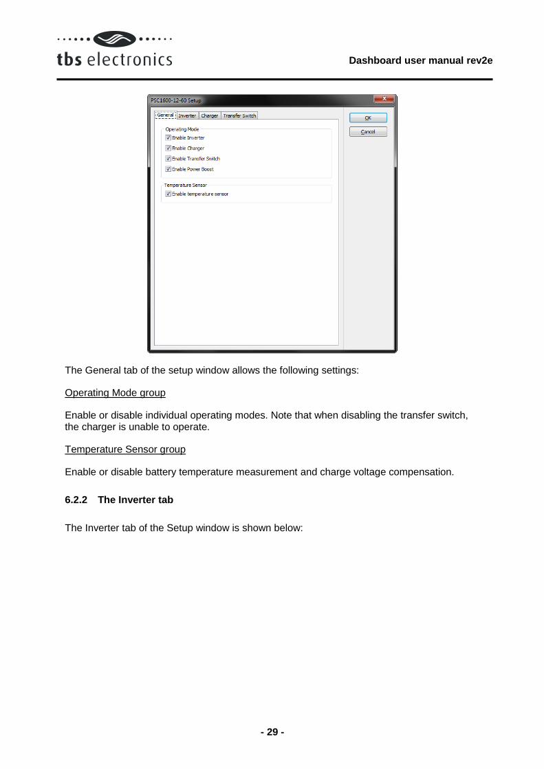
The General tab of the setup window allows the following settings:
Operating Mode group
Enable or disable individual operating modes. Note that when disabling the transfer switch, the charger is unable to operate.
Temperature Sensor group
Enable or disable battery temperature measurement and charge voltage compensation.
6.2.2 The Inverter tab
The Inverter tab of the Setup window is shown below:

Dashboard user manual rev2e
- 30 -
The Inverter tab of the setup window allows the following settings:
Output Voltage group
<Voltage>
The AC-output voltage when operating in inverter mode.
Output Frequency group
Select the AC-output frequency when operating in inverter mode.
Low Battery Protect group
<Enable>
Enable or disable low battery protection with user programmable shutdown, restart and delay values. Turning Low Battery Protect off, results in immediate inverter shutdown when the battery voltage is less than 8.0V.
<Shutdown level>
Low Battery Protect shutdown battery voltage.
<Shutdown delay>
The time the battery voltage has to be below the shutdown level before inverter shutdown.
<Restart level>
Dashboard user manual rev2e
- 31 -
The battery voltage at which the inverter continues operation after a Low Battery Protect shutdown.
<Voltage drop compensation>
Enable if you want to compensate the DC cable voltage drop. This lowers the shutdown level as more current is drawn from the battery.
Automatic Stand By (ASB) group
<Mode>
Turn ASB on or off. If on, the inverter will jump to ASB mode automatically when the connected load power consumption drops below the on level. In ASB mode the inverter pulses its output sine wave in order to detect when the connected load requires more power again. As soon as the load power demand is above the off level, the inverter will automatically jump to continuous mode delivering uninterrupted power to the load. While running in ASB mode, the Powersine Combi itself draws significantly less current from the battery. When disabled, the inverter will always run in continuous mode, which is better for critical loads like computers, clocks and AV equipment
<On level>
ABS on level. The level at which the inverter jumps to ASB mode (starts pulsing).
<Off level>
ASB off level. The level at which the inverter jumps to continuous mode (stops pulsing).
6.2.3 The Charger tab
The Charger tab of the Setup window is shown below:
Dashboard user manual rev2e
- 32 -
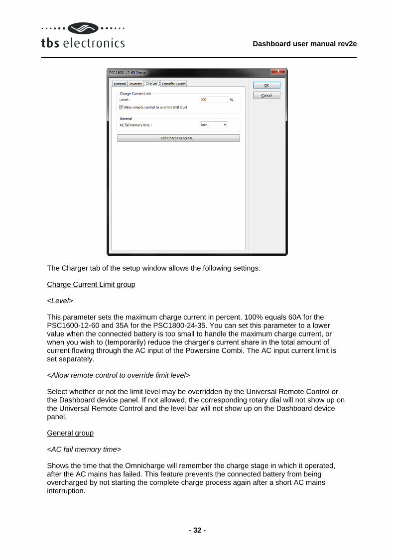
The Charger tab of the setup window allows the following settings:
Charge Current Limit group
<Level>
This parameter sets the maximum charge current in percent. 100% equals 60A for the PSC1600-12-60 and 35A for the PSC1800-24-35. You can set this parameter to a lower value when the connected battery is too small to handle the maximum charge current, or when you wish to (temporarily) reduce the charger‘s current share in the total amount of current flowing through the AC input of the Powersine Combi. The AC input current limit is set separately.
<Allow remote control to override limit level>
Select whether or not the limit level may be overridden by the Universal Remote Control or the Dashboard device panel. If not allowed, the corresponding rotary dial will not show up on the Universal Remote Control and the level bar will not show up on the Dashboard device panel.
General group
<AC fail memory time>
Shows the time that the Omnicharge will remember the charge stage in which it operated, after the AC mains has failed. This feature prevents the connected battery from being overcharged by not starting the complete charge process again after a short AC mains interruption.
Dashboard user manual rev2e
- 33 -
Edit Charge Program button
Press this button to open the Charge Program Editor and edit the custom charge program.
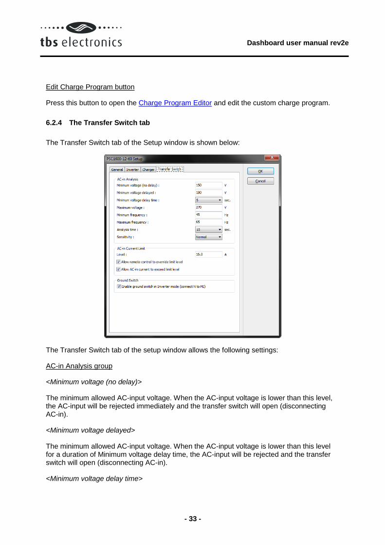
6.2.4 The Transfer Switch tab
The Transfer Switch tab of the Setup window is shown below:
The Transfer Switch tab of the setup window allows the following settings:
AC-in Analysis group
<Minimum voltage (no delay)>
The minimum allowed AC-input voltage. When the AC-input voltage is lower than this level, the AC-input will be rejected immediately and the transfer switch will open (disconnecting AC-in).
<Minimum voltage delayed>
The minimum allowed AC-input voltage. When the AC-input voltage is lower than this level for a duration of Minimum voltage delay time, the AC-input will be rejected and the transfer switch will open (disconnecting AC-in).
<Minimum voltage delay time>

Dashboard user manual rev2e
- 34 -
The time the AC-input voltage has to be lower than Minimum voltage delayed before the AC-input is rejected.
<Maximum Voltage>
The maximum allowed AC-input voltage. When the AC-input voltage is higher than this level, the AC-input will be rejected and the transfer switch will open (disconnecting AC-in).
<Minimum frequency>
The minimum allowed AC-input frequency. When the frequency is lower than this level, the AC-input is rejected and the transfer switch will open (disconnecting AC-in).
<Maximum frequency>
The maximum allowed AC-input frequency. When the frequency is higher than this level, the AC-input is rejected and the transfer switch will open (disconnecting AC-in).
<Analysis time>
The time the AC-input is analyzed before closing the transfer switch (connecting AC-in). This time is used to let the AC-input stabilize, often necessary when using generators.
<Sensitivity>
The sensitivity of the AC-input waveform fidelity analyzer. Higher sensitivity reduces the mains to inverter transfer time but is stricter on waveform fidelity. The setting Very Low disables the waveform fidelity analyzer but has the highest mains to inverter transfer time. The settings Low and Very Low can be used when the AC input signal is distorted or unstable, which could be the case when a small generator is used. The settings High and Very High can be used when the Powersine Combi is connected to a solid grid or quality generator.
AC-in Current Limit group
<Level>
Represents the maximum continuous current that the Powersine Combi will draw from the AC input source. To assure this, the Powersine Combi will either reduce the charge current automatically or (when enabled) activate the AC Input Power Boost feature which will supply the additional power demand by running the inverter in parallel with the AC
<Allow remote control to override limit level>
Select whether or not the limit level may be overridden by the Universal Remote Control or the Dashboard device panel. If not allowed, the corresponding rotary dial will not show up on the Universal Remote Control and the level bar will not show up on the Dashboard device panel.
<Allow AC-in current to exceed limit level>
Select whether or not the AC-input current may exceed the limit level. When not allowed, the Powersine Combi will open the transfer switch (disconnecting AC-in) when it is not capable

Dashboard user manual rev2e
- 35 -
of limiting the AC-in current to the limit level set. This may happen when Power Boost is disabled or the maximum boost capacity is used and the load on the AC-output requires more power.
Ground Switch group
The ground switch is an internal relay that automatically connects AC output Neutral (N) to Protective Earth (PE = chassis) in inverter mode. This enables the use of a ground fault circuit interrupter (GFCI) at the AC output of the Powersine Combi. When a non-grounded (floating-) output is required, this setting can be disabled.

Dashboard user manual rev2e
- 36 -
7 POWERSINE CONTROL
Dashboard allows display of all available parameters of your Powersine DC to AC sinewave inverter.
7.1 Powersine display panel
Using the Show Panel command or by double clicking on the desired TBS product icon in the device manager, a display panel will appear in the working area. The Powersine display panel is shown below:
This panel shows the output current indication bar and the present battery voltage and current and AC output voltage, current, power and frequency. Currently the Powersine inverters cannot be setup remotely.
Dashboard user manual rev2e
- 37 -
8 CHARGE PROGRAM EDITOR
The Charge Program Editor can be launched in two ways. When it is desirable to create or modify a charge program off-line (no Omnicharge or Powersine Combi connected to Dashboard), you can use the Charge Program Editor Wizard which can be launched from the Tools menu. This wizard will ask a few questions before entering the Editor window. Another way to launch the Charge Program Editor is from the Omnicharge or Powersine Combi setup window (see chapter 5.2). This is only possible when a such a device is connected to Dashboard.
CAUTION
The Charge Program Editor enables you to enter charge parameters that may exceed the maximum ratings of your batteries. Take extreme caution when editing charge parameters like absorption, float or equalize voltages. Entering wrong values can damage your batteries permanently or cause fire hazards. TBS Electronics BV is not responsible for any damage caused by incorrect charge program editing.
The Charge Program Editor allows you to create charge programs containing up to 10 different stages. These stages are named ‘Soft Start’, ‘Bulk’, ‘Ext. Bulk’, ‘Absorption’, ‘Analyze’, ‘Float’, ‘Pulse’, ‘Equalize’, ‘Stop’ and ‘Error’. All stages can be configured independently using different tabs inside the Charge Program Editor window. The user can also decide which stage to skip or not. For overall charge program settings, a ‘General’ tab is available as well.
8.1 The General tab
The Charge Program Editor window will open on the General tab as shown below:

Dashboard user manual rev2e
- 38 -
Pressing the Ok button will transfer the charge program to the device. Press Cancel to exit the Charge Program Editor without transferring the charge program.
When you wish to edit or create a charge program, but do not wish to transfer it yet to the device, press the Save to File… button to save the charge program for later use.
When you wish to open an earlier made charge program, press the Open File… button and select the desired file.
The following options and parameters can be edited:
Charge Program group
<Name>
Shows the name of the charge program that will be edited. The maximum length is 16 characters.
Temperature Compensation group
<Nominal battery temperature>
Shows the nominal battery temperature that will be used to calculate the correct temperature compensation voltage.
<Temperature compensation>
Shows the rate of change of charge voltage versus measured battery temperature.
<Max. allowed negative compensation>
Dashboard user manual rev2e
- 39 -
Shows maximum allowed charge voltage reduction controlled by measured battery temperature.
<Max. allowed positive compensation>
Shows maximum allowed charge voltage rise controlled by measured battery temperature.
Global Charge Timer group
<Max. charge time>
Shows the maximum allowed overall duration of a complete charge cycle.
<Max. timer start condition>
Shows the condition at which the maximum charge timer will start.
<On charge time-out go to>
Shows to which stage the charge program will jump when the maximum charger timer has expired.
Start Up group
<First stage>
Shows the first stage at which the charge program will start when a new charge cycle is initiated.
8.2 The Soft Start tab
The Soft Start stage is disabled in the factory default Flooded, GEL and AGM charge programs, but can be enabled in your custom charge program if it is desirable to for example start the charge cycle with a lower charge current until a certain battery voltage level is reached. The Soft Start tab is shown below:

Dashboard user manual rev2e
- 40 -
The following options and parameters can be edited:
<Enable stage>
When this option is checked, the soft start stage will be enabled in your charge program.
Output Status group
<Voltage>
Shows the charge voltage which will be applied to the battery under constant voltage charging conditions.
<Current Limit>
Shows the maximum charge current (%) that will be delivered to the battery under constant current conditions.
Soft Start Timers group
<Min. soft start time>
Shows the minimum allowed duration of the Soft Start stage.
<Max. soft start time>
Shows the maximum allowed duration of the Soft Start stage.
<Max. timer start condition>
Dashboard user manual rev2e
- 41 -
Shows the condition at which the soft start timer will start.
<On time-out go to>
Shows the stage to jump to when the soft start timer has expired.
Soft Start End group
<Soft start end condition>
Shows the condition at which the Soft Start stage will end.
<Soft start end delay time>
Shows the time in which ‘Soft start end condition’ must be met, before the soft start stage is considered to be finished.
<On soft start end go to>
Shows the stage to jump to when the soft start end condition has been met.
Alarm Status group
<Internal alarm contact>
The Omnicharge has one internal alarm contact designated as ‘[1]’. When this option is checked, the internal alarm contact will be activated during the complete soft start stage.
<External alarm contacts>
The Omnicharge is capable to control up to eight external alarm contacts. With the optional Alarm Output Expander kit (art.# 5055630), three external alarm contacts re available (‘[ ]1’, ‘[ ]2’ and ‘[ ]3’). Use this option to choose which external alarm contact will be activated during the complete soft start stage.
8.3 The Bulk tab
The Bulk stage is enabled in the factory default Flooded, GEL and AGM charge programs, but can be disabled in your custom charge program if desirable. The Bulk tab is shown below:

Dashboard user manual rev2e
- 42 -
The following options and parameters can be edited:
<Enable stage>
When this option is checked, the bulk stage will be enabled in your charge program.
Output Status group
<Voltage>
Shows the charge voltage which will be applied to the battery under constant voltage charging conditions.
<Current Limit>
Shows the maximum charge current (%) that will be delivered to the battery under constant current conditions.
Bulk Timers group
<Min. bulk time>
Shows the minimum allowed duration of the bulk stage.
<Max. bulk time>
Shows the maximum allowed duration of the bulk stage.
<Max. timer start condition>

Dashboard user manual rev2e
- 43 -
Shows the condition at which the bulk timer will start.
<On time-out go to>
Shows the stage to jump to when the bulk timer has expired.
Bulk End group
<Bulk end condition>
Shows the condition at which the bulk stage will end.
<Bulk end delay time>
Shows the time in which ‘Bulk end condition’ must be met, before the bulk stage is considered to be finished.
<On bulk end go to>
Shows the stage to jump to when the bulk end condition has been met.
Alarm Status group
<Internal alarm contact>
The Omnicharge has one internal alarm contact designated as ‘[1]’. When this option is checked, the internal alarm contact will be activated during the complete bulk stage.
<External alarm contacts>
The Omnicharge is capable to control up to eight external alarm contacts. With the optional Alarm Output Expander kit (art.# 5055630), three external alarm contacts are available (‘[ ]1’, ‘[ ]2’ and ‘[ ]3’). Use this option to choose which external alarm contact will be activated during the complete bulk stage.
8.4 The Ext. Bulk tab
The Ext. Bulk (Extended Bulk-) stage is disabled in the factory default Flooded, GEL and AGM charge programs, but can be enabled in your custom charge program if it is for example desirable to split the Bulk stage into two, each charging at different end voltages or current limit levels. The Ext. Bulk tab is shown below:

Dashboard user manual rev2e
- 44 -
The following options and parameters can be edited:
<Enable stage>
When this option is checked, the extended bulk stage will be enabled in your charge program.
Output Status group
<Voltage>
Shows the charge voltage which will be applied to the battery under constant voltage charging conditions.
<Current Limit>
Shows the maximum charge current (%) that will be delivered to the battery under constant current conditions.
Ext. Bulk Timers group
<Min. ext. bulk time>
Shows the minimum allowed duration of the extended bulk stage.
<Max. ext. bulk time>
Shows the maximum allowed duration of the extended bulk stage.
<Max. timer start condition>
Dashboard user manual rev2e
- 45 -
Shows the condition at which the extended bulk timer will start.
<On time-out go to>
Shows the stage to jump to when the extended bulk timer has expired.
Ext. Bulk End group
<Ext. bulk end condition>
Shows the condition at which the extended bulk stage will end.
<Ext. Bulk end delay time>
Shows the time in which ‘Ext. bulk end condition’ must be met, before the extended bulk stage is considered to be finished.
<On ext. bulk end go to>
Shows the stage to jump to when the extended bulk end condition has been met.
Alarm Status group
<Internal alarm contact>
The Omnicharge has one internal alarm contact designated as ‘[1]’. When this option is checked, the internal alarm contact will be activated during the complete extended bulk stage.
<External alarm contacts>
The Omnicharge is capable to control up to eight external alarm contacts. With the optional Alarm Output Expander kit (art.# 5055630), three external alarm contacts are available (‘[ ]1’, ‘[ ]2’ and ‘[ ]3’). Use this option to choose which external alarm contact will be activated during the complete extended bulk stage.
8.5 The Absorption tab
The absorption stage is enabled in the factory default Flooded, GEL and AGM charge programs, but can be disabled in your custom charge program if desirable. The Absorption tab is shown below:

Dashboard user manual rev2e
- 46 -
The following options and parameters can be edited:
<Enable stage>
When this option is checked, the absorption stage will be enabled in your charge program.
Output Status group
<Voltage>
Shows the charge voltage which will be applied to the battery under constant voltage charging conditions.
<Current Limit>
Shows the maximum charge current (%) that will be delivered to the battery under constant current conditions.
Absorption Timers group
<Min. absorption time>
Shows the minimum allowed duration of the absorption stage.
<Max. absorption time>
Shows the maximum allowed duration of the absorption stage.
<Max. timer start condition>
Dashboard user manual rev2e
- 47 -
Shows the condition at which the absorption timer will start.
<On time-out go to>
Shows the stage to jump to when the absorption timer has expired.
Absorption End group
<Absorption end condition>
Shows the condition at which the absorption stage will end.
<Absorption end delay time>
Shows the time in which ‘Absorption end condition’ must be met, before the absorption stage is considered to be finished.
<On absorption end go to>
Shows the stage to jump to when the absorption end condition has been met.
Alarm Status group
<Internal alarm contact>
The Omnicharge has one internal alarm contact designated as ‘[1]’. When this option is checked, the internal alarm contact will be activated during the complete absorption stage.
<External alarm contacts>
The Omnicharge is capable to control up to eight external alarm contacts. With the optional Alarm Output Expander kit (art.# 5055630), three external alarm contacts are available (‘[ ]1’, ‘[ ]2’ and ‘[ ]3’). Use this option to choose which external alarm contact will be activated during the complete absorption stage.
8.6 The Analyze tab
The analyze stage is disabled in the factory default Flooded, GEL and AGM charge programs, but can be enabled in your custom charge program if desirable. This stage can for example be used to check the voltage response of the battery, after a certain charge program stage has been applied to the battery.
The analyze stage will allow the battery voltage to drop, by disabling the charger’s output and monitor if the battery voltage does not drop too deep within a certain amount of time. The Analyze Timer group is used for determining the timeframe wherein the voltage drop is monitored. The Analyze Fail group is used to detect if the battery voltage drops to deep.
In the example below, the analyze stage will take 2 minutes. If within this 2 minute timeframe the voltage is not lower than or equal to 12.5V for 5 seconds, the charger will jump to the float stage. If the voltage is lower than or equal to 12.5V for 5 seconds, the charger will jump to the error stage.

Dashboard user manual rev2e
- 48 -
The Analyze tab is shown below:
The following options and parameters can be edited:
<Enable stage>
When this option is checked, the analyze stage will be enabled in your charge program.
Analyze Timer group
<Max. analyze time>
Shows the maximum duration of the analyze stage.
<On time-out go to>
Shows the stage to jump to when the ‘Max. analyze time’ has expired.
Analyze Fail group
<Analyze fail condition>
Shows the condition at which the analyze stage will fail.
<Analyze fail delay time>
Shows the time in which ‘Analyze fail condition’ must be met, before the analyze stage is considered to be failed.
<On analyze fail go to>
Dashboard user manual rev2e
- 49 -
Shows the stage to jump to when the analyze fail condition has been met.
Alarm Status group
<Internal alarm contact>
The Omnicharge has one internal alarm contact designated as ‘[1]’. When this option is checked, the internal alarm contact will be activated during the complete analyze stage.
<External alarm contacts>
The Omnicharge is capable to control up to eight external alarm contacts. With the optional Alarm Output Expander kit (art.# 5055630), three external alarm contacts are available (‘[ ]1’, ‘[ ]2’ and ‘[ ]3’). Use this option to choose which external alarm contact will be activated during the complete analyze stage.
8.7 The Float tab
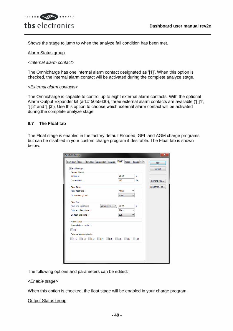
The Float stage is enabled in the factory default Flooded, GEL and AGM charge programs, but can be disabled in your custom charge program if desirable. The Float tab is shown below:
The following options and parameters can be edited:
<Enable stage>
When this option is checked, the float stage will be enabled in your charge program.
Output Status group
Dashboard user manual rev2e
- 50 -
<Voltage>
Shows the charge voltage which will be applied to the battery under constant voltage charging conditions.
<Current Limit>
Shows the maximum charge current (%) that will be delivered to the battery under constant current conditions.
Float Timer group
<Max. float time>
Shows the maximum allowed duration of the float stage.
<On time-out go to>
Shows the stage to jump to when the float timer has expired.
Float End group
<Float end condition>
Shows the condition at which the float stage will end.
<Float end delay time>
Shows the time in which ‘Float end condition’ must be met, before the float stage is considered to be finished.
<On float end go to>
Shows the stage to jump to when the float end condition has been met.
Alarm Status group
<Internal alarm contact>
The Omnicharge has one internal alarm contact designated as ‘[1]’. When this option is checked, the internal alarm contact will be activated during the complete float stage.
<External alarm contacts>
The Omnicharge is capable to control up to eight external alarm contacts. With the optional Alarm Output Expander kit (art.# 5055630), three external alarm contacts are available (‘[ ]1’, ‘[ ]2’ and ‘[ ]3’). Use this option to choose which external alarm contact will be activated during the complete float stage.
8.8 The Pulse tab

Dashboard user manual rev2e
- 51 -
The Pulse stage is enabled in the factory default Flooded, GEL and AGM charge programs, but can be disabled in your custom charge program if desirable. This stage can be used to deliver a short ‘refresh’ charge to the battery when it is connected to the charger for an extended time. The Pulse tab is shown below:
The following options and parameters can be edited:
<Enable stage>
When this option is checked, the pulse stage will be enabled in your charge program.
Output Status group
<Voltage>
Shows the charge voltage which will be applied to the battery under constant voltage charging conditions.
<Current Limit>
Shows the maximum charge current (%) that will be delivered to the battery under constant current conditions.
Pulse Timer group
<Max.pulse time>
Shows the maximum allowed duration of the pulse stage.
<On time-out go to>

Dashboard user manual rev2e
- 52 -
Shows the stage to jump to when the pulse timer has expired.
Pulse End group
<Pulse end condition>
Shows the condition at which the pulse stage will end.
<Pulse end delay time>
Shows the time in which ‘Pulse end condition’ must be met, before the pulse stage is considered to be finished.
<On pulse end go to>
Shows the stage to jump to when the pulse end condition has been met.
Alarm Status group
<Internal alarm contact>
The Omnicharge has one internal alarm contact designated as ‘[1]’. When this option is checked, the internal alarm contact will be activated during the complete pulse stage.
<External alarm contacts>
The Omnicharge is capable to control up to eight external alarm contacts. With the optional Alarm Output Expander kit (art.# 5055630), three external alarm contacts are available (‘[ ]1’, ‘[ ]2’ and ‘[ ]3’). Use this option to choose which external alarm contact will be activated during the complete pulse stage.
8.9 The Equalize tab
The Equalize stage is enabled in the factory default Flooded charge program and disabled in the factory default GEL and AGM charge programs. Please make sure that if you wish to enable this stage, you will only be charging battery types which are allowed to be equalized. Sealed batteries can explode when equalizing these! Enabling the equalize stage does not mean that the charger will automatically equalize your battery, but only that it will respond to pressing the equalize switch at the bottom side of your Omnicharge battery charger. The Equalize tab is shown below:

Dashboard user manual rev2e
- 53 -
The following options and parameters can be edited:
<Enable stage>
When this option is checked, the equalize stage can be activated by pressing the recessed equalize switch at the bottom side of your Omnicharge battery charger. Please note that the equalize stage can only be activated when the charger is operating in the float or pulse stage.
Output Status group
<Voltage>
Shows the charge voltage which will be applied to the battery under constant voltage charging conditions.
<Current Limit>
Shows the maximum charge current (%) that will be delivered to the battery under constant current conditions.
Equalize Timers group
<Min. equalize time>
Shows the minimum allowed duration of the equalize stage.
<Max. equalize time>
Shows the maximum allowed duration of the equalize stage.

Dashboard user manual rev2e
- 54 -
<Max. timer start condition>
Shows the condition at which the equalize timer will start.
<On time-out go to>
Shows the stage to jump to when the equalize timer has expired.
Equalize End group
<Equalize end condition>
Shows the condition at which the equalize stage will end.
<Equalize end delay time>
Shows the time in which ‘Equalize end condition’ must be met, before the equalize stage is considered to be finished.
<On equalize end go to>
Shows the stage to jump to when the equalize end condition has been met.
Alarm Status group
<Internal alarm contact>
The Omnicharge has one internal alarm contact designated as ‘[1]’. When this option is checked, the internal alarm contact will be activated during the complete equalize stage.
<External alarm contacts>
The Omnicharge is capable to control up to eight external alarm contacts. With the optional Alarm Output Expander kit (art.# 5055630), three external alarm contacts are available (‘[ ]1’, ‘[ ]2’ and ‘[ ]3’). Use this option to choose which external alarm contact will be activated during the complete equalize stage.
8.10 The Stop tab
The stop stage is disabled in the factory default Flooded, GEL and AGM charge programs, but can be enabled in your custom charge program if desirable. This stage can be used to stop the charge process after the absorption stage, instead of going to the float stage. In the error stage the charger output will be turned off. The Stop tab is shown below:

Dashboard user manual rev2e
- 55 -
The following options and parameters can be edited:
<Enable stage>
When this option is checked, the stop stage will be enabled in your charge program.
Stop Timer group
<Max. stop time>
Shows the maximum duration of the stop stage.
<On time-out go to>
Shows the stage to jump to when the ‘Max. stop time’ has expired.
Stop End group
<Stop end condition>
Shows the condition at which the stop stage will end.
<Stop end delay time>
Shows the time in which ‘Stop end condition’ must be met, before the stop stage is considered to be finished.
<On stop end go to>
Shows the stage to jump to when the stop end condition has been met.
Dashboard user manual rev2e
- 56 -
Alarm Status group
<Internal alarm contact>
The Omnicharge has one internal alarm contact designated as ‘[1]’. When this option is checked, the internal alarm contact will be activated during the complete stop stage.
<External alarm contacts>
The Omnicharge is capable to control up to eight external alarm contacts. With the optional Alarm Output Expander kit (art.# 5055630), three external alarm contacts are available (‘[ ]1’, ‘[ ]2’ and ‘[ ]3’). Use this option to choose which external alarm contact will be activated during the complete stop stage.
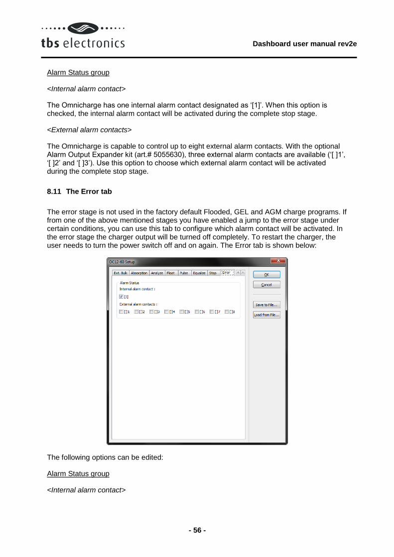
8.11 The Error tab
The error stage is not used in the factory default Flooded, GEL and AGM charge programs. If from one of the above mentioned stages you have enabled a jump to the error stage under certain conditions, you can use this tab to configure which alarm contact will be activated. In the error stage the charger output will be turned off completely. To restart the charger, the user needs to turn the power switch off and on again. The Error tab is shown below:
The following options can be edited:
Alarm Status group
<Internal alarm contact>

Dashboard user manual rev2e
- 57 -
The Omnicharge has one internal alarm contact designated as ‘[1]’. When this option is checked, the internal alarm contact will be activated until the user manually resets the charger.
<External alarm contacts>
The Omnicharge is capable to control up to eight external alarm contacts. With the optional Alarm Output Expander kit (art.# 5055630), three external alarm contacts are available (‘[ ]1’, ‘[ ]2’ and ‘[ ]3’). Use this option to choose which external alarm contact will be activated during the error stage.
Dashboard user manual rev2e
- 58 -
9 END USER LICENSE AGREEMENT
IMPORTANT READ CAREFULLY
SOFTWARE PRODUCT here means Software, image files, all accompanying files, data and materials received with your order of Dashboard.
Please read the following terms and conditions carefully before using this SOFTWARE PRODUCT.
By clicking on the “I ACCEPT” button, by opening the package that contains the SOFTWARE PRODUCT, or by copying, downloading, accessing or otherwise using the SOFTWARE PRODUCT, you agree to be bound by the terms of this License and you represent that you are authorized to enter into this Agreement on behalf of your corporate entity (if applicable). If you do not agree to any of the terms of this License or do not wish to be bound by the terms of this License, click the “I DO NOT ACCEPT” button, and do not install, access, use or distribute the SOFTWARE PRODUCT. Your use, distribution or installation of this copy of this SOFTWARE PRODUCT indicates your acceptance of this License.
TBS Electronics BV is the owner of the copyright of this SOFTWARE PRODUCT. All of its derivatives, title and accompanying materials are the exclusive property of TBS Electronics BV. All rights of any kind, which are not expressly granted in this License, are entirely and exclusively reserved to and by TBS Electronics BV. You may not rent, lease, transfer, modify, translate, reverse engineer, de-compile, disassemble or create derivative works based on this SOFTWARE PRODUCT. You may not make access to SOFTWARE PRODUCT available to others in connection with a service bureau, application service provider, or similar business. There are no third party beneficiaries of any promises, obligations or representations made by TBS Electronics BV herein.
This SOFTWARE PRODUCT, all accompanying files, data and materials, are distributed "AS IS" and with no warranties of any kind, whether express or implied. The user must assume all risk of using the SOFTWARE PRODUCT. This disclaimer of warranty constitutes an essential part of the agreement.
Any liability of TBS Electronics BV will be limited exclusively to refund of purchase price. In addition, in no event shall TBS Electronics BV, or its principals, shareholders, officers, employees, affiliates, contractors, subsidiaries, or parent organizations, be liable for any incidental, consequential, punitive or any other damages (including, but not limited to, procurement of substitute goods or services; Loss of use, data, or profits, or business interruption) whatsoever relating to the use of SOFTWARE PRODUCT.
In addition, in no event does TBS Electronics BV authorize you to use this SOFTWARE PRODUCT in applications or systems where SOFTWARE PRODUCT 's failure to perform can reasonably be expected to result in a physical injury, or in loss of life. Any such use by you is entirely at your own risk, and you agree to hold TBS Electronics BV harmless from any claims or losses relating to such unauthorized use.
Warrantee covers defects in the SOFTWARE PRODUCT, which prevents successfully installing the SOFTWARE PRODUCT on the buyer's computer provided that the buyer's computer meets the SOFTWARE PRODUCT's minimum system requirements. Warrantee does not cover fitness of purpose, not meeting of expectations or needs in the mind of the

Dashboard user manual rev2e
- 59 -
buyer.
This SOFTWARE PRODUCT is for personal use only and may be installed and used by on only one computer. Its component parts may not be separated for use on more than one computer. SOFTWARE PRODUCT may be accessed through a network only after obtaining a site license. All components accompanying the software are copyrighted by TBS Electronics BV and may not be taken apart, modified, used or published with other software or means except with the SOFTWARE PRODUCT software and may not be distributed or copied in any manner.
You may not disclose to other persons the data or techniques relating to this SOFTWARE PRODUCT that you know or should know that it is a trade secret of TBS Electronics BV in any manner that will cause damage to TBS Electronics BV.
This SOFTWARE PRODUCT and all services provided may be used for lawful purposes only. Transmission, storage, or presentation of any information, data or material in violation of the buyer's Country, State or City law is strictly prohibited. This includes, but is not limited to: Copyrighted material, material we judge to be threatening or obscene, or material protected by trade secret and other statute. You agree to indemnify and hold TBS Electronics BV harmless from any claims resulting from the use of this SOFTWARE PRODUCT, which may damage any other party.
This Agreement constitutes the entire statement of the Agreement between the parties on the subject matter, and merges and supersedes all other or prior understandings, purchase orders, agreements and arrangements. This Agreement shall be governed by the laws of The Netherlands.
Waarderveldweg 3 2031 BK Haarlem The Netherlands
Tel +31 23 5149900 Fax +31 23 5322583 Email: [email protected]