Embed Size (px)
Citation preview
DatasheetMarch 2017
Daniel™ 3812 Two-Path Liquid Ultrasonic Flow Meter

DatasheetLiquid Ultrasonic Flow Meter
www.Emerson.com
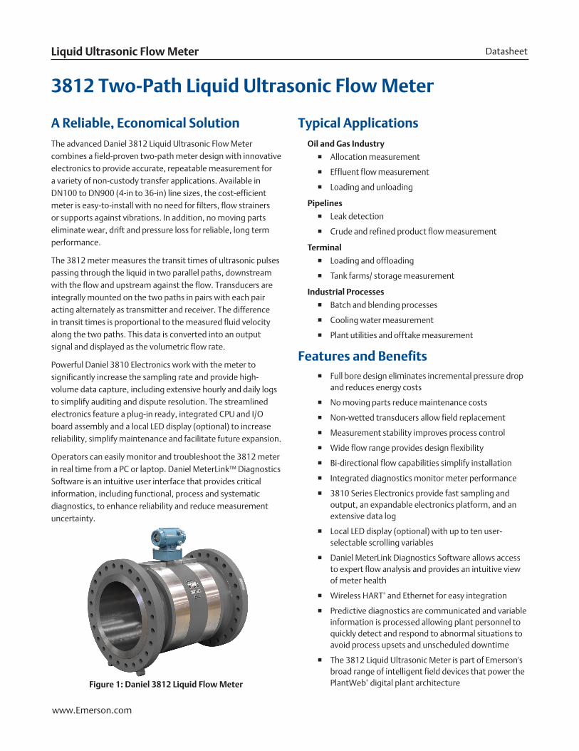
A Reliable, Economical Solution The advanced Daniel 3812 Liquid Ultrasonic Flow Meter combines a field-proven two-path meter design with innovative electronics to provide accurate, repeatable measurement for a variety of non-custody transfer applications. Available in DN100 to DN900 (4-in to 36-in) line sizes, the cost-efficient meter is easy-to-install with no need for filters, flow strainers or supports against vibrations. In addition, no moving parts eliminate wear, drift and pressure loss for reliable, long term performance.
The 3812 meter measures the transit times of ultrasonic pulses passing through the liquid in two parallel paths, downstream with the flow and upstream against the flow. Transducers are integrally mounted on the two paths in pairs with each pair acting alternately as transmitter and receiver. The difference in transit times is proportional to the measured fluid velocity along the two paths. This data is converted into an output signal and displayed as the volumetric flow rate.
Powerful Daniel 3810 Electronics work with the meter to significantly increase the sampling rate and provide high-volume data capture, including extensive hourly and daily logs to simplify auditing and dispute resolution. The streamlined electronics feature a plug-in ready, integrated CPU and I/O board assembly and a local LED display (optional) to increase reliability, simplify maintenance and facilitate future expansion.
Operators can easily monitor and troubleshoot the 3812 meter in real time from a PC or laptop. Daniel MeterLink™ Diagnostics Software is an intuitive user interface that provides critical information, including functional, process and systematic diagnostics, to enhance reliability and reduce measurement uncertainty.
3812 Two-Path Liquid Ultrasonic Flow Meter
Typical ApplicationsOil and Gas Industry
� Allocation measurement
� Effluent flow measurement
� Loading and unloading
Pipelines
� Leak detection
� Crude and refined product flow measurement
Terminal
� Loading and offloading
� Tank farms/ storage measurement
Industrial Processes
� Batch and blending processes
� Cooling water measurement
� Plant utilities and offtake measurement
Features and Benefits � Full bore design eliminates incremental pressure drop
and reduces energy costs
� No moving parts reduce maintenance costs
� Non-wetted transducers allow field replacement
� Measurement stability improves process control
� Wide flow range provides design flexibility
� Bi-directional flow capabilities simplify installation
� Integrated diagnostics monitor meter performance
� 3810 Series Electronics provide fast sampling and output, an expandable electronics platform, and an extensive data log
� Local LED display (optional) with up to ten user-selectable scrolling variables
� Daniel MeterLink Diagnostics Software allows access to expert flow analysis and provides an intuitive view of meter health
� Wireless HART® and Ethernet for easy integration
� Predictive diagnostics are communicated and variable information is processed allowing plant personnel to quickly detect and respond to abnormal situations to avoid process upsets and unscheduled downtime
� The 3812 Liquid Ultrasonic Meter is part of Emerson's broad range of intelligent field devices that power the PlantWeb® digital plant architectureFigure 1: Daniel 3812 Liquid Flow Meter
March 2017Daniel 3812
www.Emerson.com
Meter SpecificationsCharacteristics
� Transit-time based measurement
� Full bore spool piece with integral mount transducers
� Dual-path (four transducer) chordal design
Meter Performance
� Linearity is ± 0.30% of measured value over a 1.2 to 12.2 m/s (4 to 40 ft/s) range
� Repeatability is ± 0.10% of measured value
Velocity Range
� 1.2 to 12.2 m/s (4 to 40 ft/s) with an over-range of 0.3 to 14.6 m/s (1 to 48 ft/s)
Transducer Capsule
� Field replaceable
� Intrinsically safe
Electronics PerformancePower
� 10.4 to 36 VDC
� 8 watts typical; 15 watts maximum
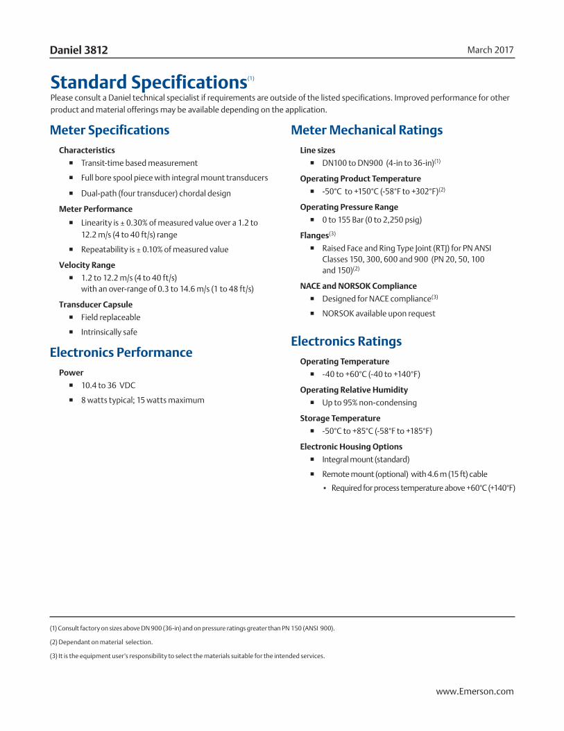
Standard Specifications(1)
Please consult a Daniel technical specialist if requirements are outside of the listed specifications. Improved performance for other product and material offerings may be available depending on the application.
(1) Consult factory on sizes above DN 900 (36-in) and on pressure ratings greater than PN 150 (ANSI 900).
(2) Dependant on material selection.
(3) It is the equipment user’s responsibility to select the materials suitable for the intended services.
Meter Mechanical Ratings Line sizes
� DN100 to DN900 (4-in to 36-in)(1)
Operating Product Temperature
� -50°C to +150°C (-58°F to +302°F)(2)
Operating Pressure Range
� 0 to 155 Bar (0 to 2,250 psig)
Flanges(3)
� Raised Face and Ring Type Joint (RTJ) for PN ANSI Classes 150, 300, 600 and 900 (PN 20, 50, 100 and 150)(2)
NACE and NORSOK Compliance
� Designed for NACE compliance(3)
� NORSOK available upon request
Electronics RatingsOperating Temperature
� -40 to +60°C (-40 to +140°F)
Operating Relative Humidity
� Up to 95% non-condensing
Storage Temperature
� -50°C to +85°C (-58°F to +185°F)
Electronic Housing Options
� Integral mount (standard)
� Remote mount (optional) with 4.6 m (15 ft) cable
▪ Required for process temperature above +60°C (+140°F)
DatasheetLiquid Ultrasonic Flow Meter
www.Emerson.com
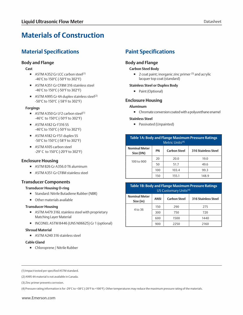
Material Specifications
Body and FlangeCast
� ASTM A352 Gr LCC carbon steel(1) -46°C to 150°C (-50°F to 302°F)
� ASTM A351 Gr CF8M 316 stainless steel -46°C to 150°C (-50°F to 302°F)
� ASTM A995 Gr 4A duplex stainless steel(2) -50°C to 150°C (-58°F to 302°F)
Forgings
� ASTM A350 Gr LF2 carbon steel(1) -46°C to 150°C (-50°F to 302°F)
� ASTM A182 Gr F316 SS -46°C to 150°C (-50°F to 302°F)
� ASTM A182 Gr F51 duplex SS -50°C to 150°C (-58°F to 302°F)
� ASTM A105 carbon steel -29° C to 150°C (-20°F to 302°F)
Enclosure Housing � ASTM B26 Gr A356.0 T6 aluminum
� ASTM A351 Gr CF8M stainless steel
Transducer Components Transducer Housing O-ring
� Standard: Nitrile Butadiene Rubber (NBR)
� Other materials available
Transducer Housing
� ASTM A479 316L stainless steel with proprietary Matching Layer Material
� INCONEL ASTM B446 (UNS N06625) Gr 1 (optional)
Shroud Material
� ASTM A240 316 stainless steel
Cable Gland
� Chloroprene / Nitrile Rubber
Materials of Construction
Paint Specifications
Body and FlangeCarbon Steel Body
� 2 coat paint; inorganic zinc primer (3) and acrylic lacquer top coat (standard)
Stainless Steel or Duplex Body
� Paint (Optional)
Enclosure HousingAluminum
� Chromate conversion coated with a polyurethane enamel
Stainless Steel
� Passivated (Unpainted)
Table 1A: Body and Flange Maximum Pressure Ratings Metric Units(4)
Nominal Meter
Size (DN)PN Carbon Steel 316 Stainless Steel
100 to 90020 20.0 19.0
50 51.7 49.6
100 103.4 99.3
150 155.1 148.9
Table 1B: Body and Flange Maximum Pressure Ratings US Customary Units(4)
Nominal Meter
Size (in)ANSI Carbon Steel 316 Stainless Steel
4 to 36150 290 275
300 750 720
600 1500 1440
900 2250 2160
(1) Impact tested per specified ASTM standard.
(2) A995 4A material is not available in Canada.
(3) Zinc primer prevents corrosion.
(4) Pressure rating information is for -29°C to +38°C (-20°F to +100°F). Other temperatures may reduce the maximum pressure rating of the materials.

March 2017Daniel 3812
www.Emerson.com
Standard Flow Ranges
Table 2A: Daniel 3812 Flow Ranges Metric Units
Nominal
Meter Size (DN) Meter I.D. (mm) Pipe Schedule
Fluid Velocity (m/s) Flow Rate (m3/hr)
Min Max Over-Range Min Max Over-Range
100 102.3 Sch 40 0.61 12.2 14.6 18 360 433
150 154.1 Sch 40 0.61 12.2 14.6 41 818 982
200 202.7 Sch 40 0.61 12.2 14.6 71 1,417 1,700
250 254.5 Sch 40 0.61 12.2 14.6 112 2,233 2,679
300 303.2 Sch 40 0.61 12.2 14.6 158 3,170 3,803
350 333.4 SCh 40 0.61 12.2 14.6 192 3,831 4,597
400 381.0 Sch 40 0.61 12.2 14.6 250 5,004 6,005
450 428.65 Sch 40 0.61 12.2 14.6 317 6,334 7,601
500 477.82 Sch 40 0.61 12.2 14.6 394 7,871 9,445
600 574.65 Sch 40 0.61 12.2 14.6 569 11,383 13,660
750 742.95 STD 0.61 12.2 14.6 951 19,028 22,833
900 895.35 STD 0.61 12.2 14.6 1,382 27,635 33,162
Table 2B: Daniel 3812 Flow Ranges US Customary Units
Nominal
Meter Size (in) Meter I.D. (in)
Pipe
Schedule
Fluid Velocity (ft/s) Flow Rate (BPH) Flow Rate (GPM)
Min Max Over-Range Min Max Over-Range Min Max Over-Range
4 4.026 Sch 40 2 40 48 113 2,267 2,721 79 1,587 1,905
6 6.065 Sch 40 2 40 48 257 5,146 6,175 180 3,602 4,322
8 7.981 Sch 40 2 40 48 446 8,910 10,692 312 6,237 7,485
10 10.020 Sch 40 2 40 48 702 14,045 16,853 492 9,831 11,797
12 11.938 Sch 40 2 40 48 997 19,936 23,923 698 13,955 16,746
14 13.124 Sch 40 2 40 48 1,205 24,094 28,913 843 16,866 20,239
16 15.000 Sch 40 2 40 48 1,574 31,474 37,769 1,102 22,032 26,438
18 16.876 Sch 40 2 40 48 1,992 39,839 47,807 1,394 27,887 33,465
20 18.812 Sch 40 2 40 48 2,475 49,504 59,405 1,733 34,653 41,583
24 22.624 Sch 40 2 40 48 3,580 71,599 85,920 2,506 50,120 60,144
30 29.25 STD 2 40 48 5984 119,680 143,617 4189 83,776 100,531
36 35.25 STD 2 40 48 8691 173,816 208,580 6084 121,671 146,005
DatasheetLiquid Ultrasonic Flow Meter
www.Emerson.com
(1) The analog-to-digital conversion accuracy is within ±0.05% of full scale over the operating temperature range.
(2) AI-1 and AI-2 are electronically isolated and operate in sink mode. The input contains a series resistance so HART® Communicators can be connected to configure sensors.
(3) A 24 Volt DC power supply is available to provide power to the sensors.
(4) The analog output zero scale offset error is within ±0.1% of full scale and gain error is within ±0.2% of full scale. The total output drift is within ±50 ppm of full scale per °C.
Table 4: CPU Module I/O Connections
I/O Connection Type Qty Description
Communication
Serial Communications Serial RS232/RS485 Port
1 ▪ Modbus RTU/ASCII
▪ 115 kbps baud rate
▪ RS232/RS485 Full Duplex
▪ RS485 Half Duplex
Ethernet Port (TCP/IP) 100BaseT 1 ▪ Modbus TCP
Digital and Analog Inputs
Digital Input(1) Contact Closure 1 ▪ Status
▪ Single polarity
Analog Inputs(2) 4-20 mA 2 ▪ AI-1 Temperature(3)
▪ AI-2 Pressure (3)
Digital, Analog and Frequency Outputs
Frequency/Digital Outputs TTL/Open Collector 3 ▪ User Configurable
Analog Outputs(2, 4) 4-20 mA 2 ▪ Independently configurable analog outputs
▪ HART® 7 Compliant, consult factory for HART 5Note: Maximum wire gauge is 18 AWG.
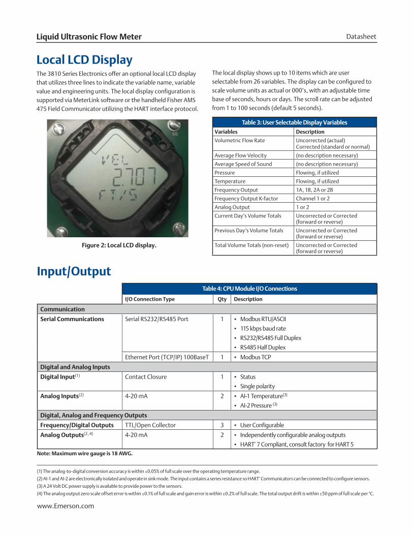
Local LCD Display
Input/Output
The 3810 Series Electronics offer an optional local LCD display that utilizes three lines to indicate the variable name, variable value and engineering units. The local display configuration is supported via MeterLink software or the handheld Fisher AMS 475 Field Communicator utilizing the HART interface protocol.
The local display shows up to 10 items which are user selectable from 26 variables. The display can be configured to scale volume units as actual or 000’s, with an adjustable time base of seconds, hours or days. The scroll rate can be adjusted from 1 to 100 seconds (default 5 seconds).
Table 3: User Selectable Display Variables
Variables Description
Volumetric Flow Rate Uncorrected (actual) Corrected (standard or normal)
Average Flow Velocity (no description necessary)
Average Speed of Sound (no description necessary)
Pressure Flowing, if utilized
Temperature Flowing, if utilized
Frequency Output 1A, 1B, 2A or 2B
Frequency Output K-factor Channel 1 or 2
Analog Output 1 or 2
Current Day’s Volume Totals Uncorrected or Corrected (forward or reverse)
Previous Day’s Volume Totals Uncorrected or Corrected (forward or reverse)
Total Volume Totals (non-reset) Uncorrected or Corrected (forward or reverse)
Figure 2: Local LCD display.
March 2017Daniel 3812
www.Emerson.com
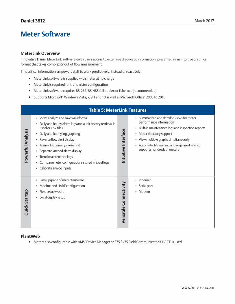
Meter Software
MeterLink OverviewInnovative Daniel MeterLink software gives users access to extensive diagnostic information, presented in an intuitive graphical format that takes complexity out of flow measurement.
This critical information empowers staff to work predictively, instead of reactively.
� MeterLink software is supplied with meter at no charge
� MeterLink is required for transmitter configuration
� MeterLink software requires RS-232, RS-485 full duplex or Ethernet (recommended)
� Supports Microsoft® Windows Vista, 7, 8.1 and 10 as well as Microsoft Office® 2003 to 2016
Table 5: MeterLink Features
Pow
erfu
l An
alys
is
▪ View, analyze and save waveforms
▪ Daily and hourly alarm logs and audit history retrieval in Excel or CSV files
▪ Daily and hourly log graphing
▪ Reverse flow alert display
▪ Alarms list primary cause first
▪ Separate latched alarm display
▪ Trend maintenance logs
▪ Compare meter configurations stored in Excel logs
▪ Calibrate analog inputs
Intu
itiv
e In
terf
ace
▪ Summarized and detailed views for meter performance information
▪ Built-in maintenance logs and inspection reports
▪ Meter directory support
▪ View multiple graphs simultaneously
▪ Automatic file naming and organized saving, supports hundreds of meters
Qu
ick
Star
tup
▪ Easy upgrade of meter firmware
▪ Modbus and HART configuration
▪ Field setup wizard
▪ Local display setup
Ver
sati
le C
on
nec
tivi
ty
▪ Ethernet
▪ Serial port
▪ Modem
PlantWeb � Meters also configurable with AMS™ Device Manager or 375 / 475 Field Communicator if HART® is used
DatasheetLiquid Ultrasonic Flow Meter
www.Emerson.com
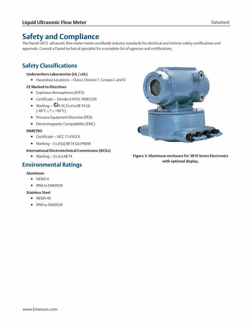
Safety and ComplianceThe Daniel 3812 ultrasonic flow meter meets worldwide industry standards for electrical and intrinsic safety certifications and approvals. Consult a Daniel technical specialist for a complete list of agencies and certifications.
Safety ClassificationsUnderwriters Laboratories (UL / cUL)
� Hazardous Locations — Class I, Division 1, Groups C and D
CE Marked to Directives
� Explosive Atmospheres (ATEX)
� Certificate — Demko II ATEX 1006133X
� Marking — II 2G Ex d ia IIB T4 Gb (-40°C ≤ T ≤ +60°C)
� Pressure Equipment Directive (PED)
� Electromagnetic Compatibility (EMC)
INMETRO
� Certificate — NCC 11.0163 X
� Marking — Ex d [ia] IIB T4 Gb IP66W
International Electrotechnical Commission (IECEx)
� Marking — Ex d ia IIB T4
Environmental RatingsAluminum
� NEMA 4
� IP66 to EN60529
Stainless Steel
� NEMA 4X
� IP66 to EN60529
Figure 3: Aluminum enclosure for 3810 Series Electronics with optional display.
March 2017Daniel 3812
www.Emerson.com
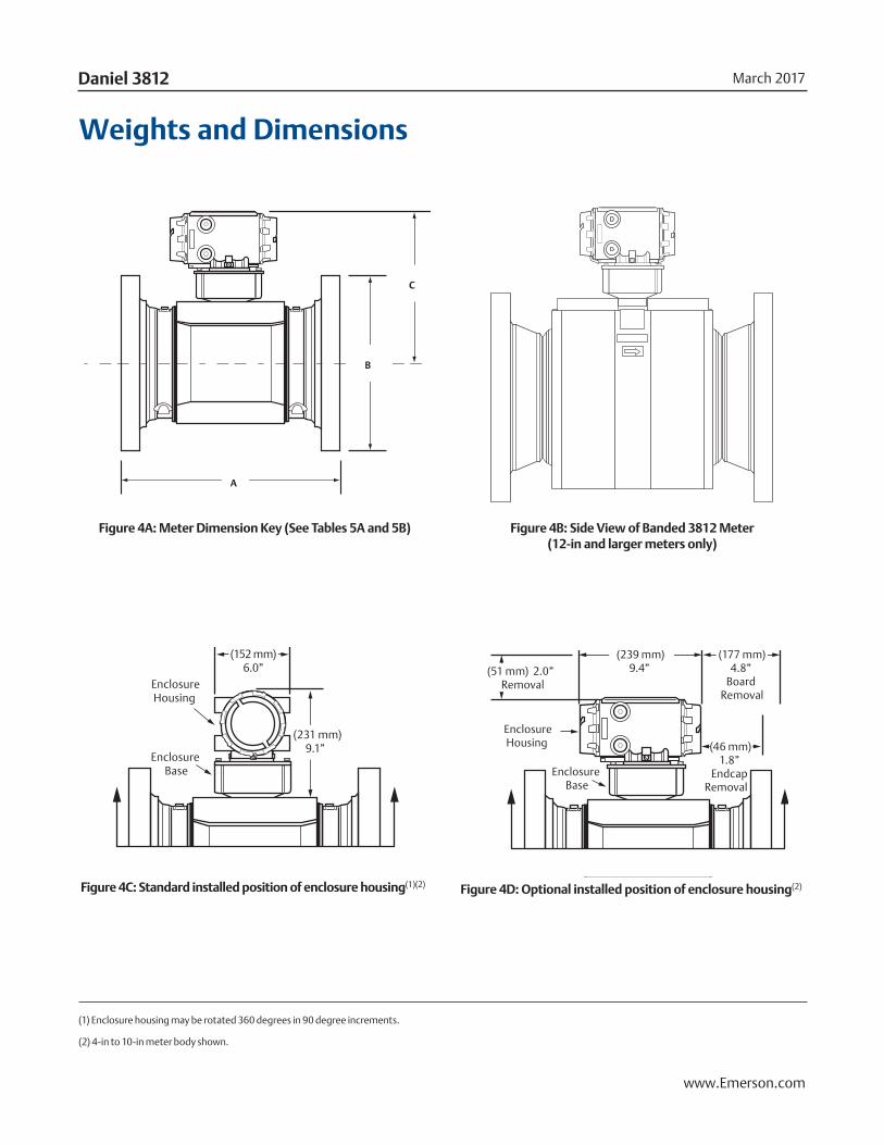
Weights and Dimensions
A
C
B
EnclosureHousing
Enclosure Base
EnclosureHousing
(51 mm) 2.0” Removal
(231 mm)9.1”
(239 mm)9.4”
(46 mm)1.8”
Endcap Removal
(177 mm)4.8”
Board Removal
(152 mm)6.0”
Enclosure Base
A
C
B
EnclosureHousing
Enclosure Base
EnclosureHousing
(51 mm) 2.0” Removal
(231 mm)9.1”
(239 mm)9.4”
(46 mm)1.8”
Endcap Removal
(177 mm)4.8”
Board Removal
(152 mm)6.0”
Enclosure Base
A
C
B
EnclosureHousing
Enclosure Base
EnclosureHousing
(51 mm) 2.0” Removal
(231 mm)9.1”
(239 mm)9.4”
(46 mm)1.8”
Endcap Removal
(177 mm)4.8”
Board Removal
(152 mm)6.0”
Enclosure Base
Figure 4D: Optional installed position of enclosure housing(2)
Figure 4A: Meter Dimension Key (See Tables 5A and 5B) Figure 4B: Side View of Banded 3812 Meter (12-in and larger meters only)
Figure 4C: Standard installed position of enclosure housing(1)(2)
(1) Enclosure housing may be rotated 360 degrees in 90 degree increments.
(2) 4-in to 10-in meter body shown.
DatasheetLiquid Ultrasonic Flow Meter
www.Emerson.com
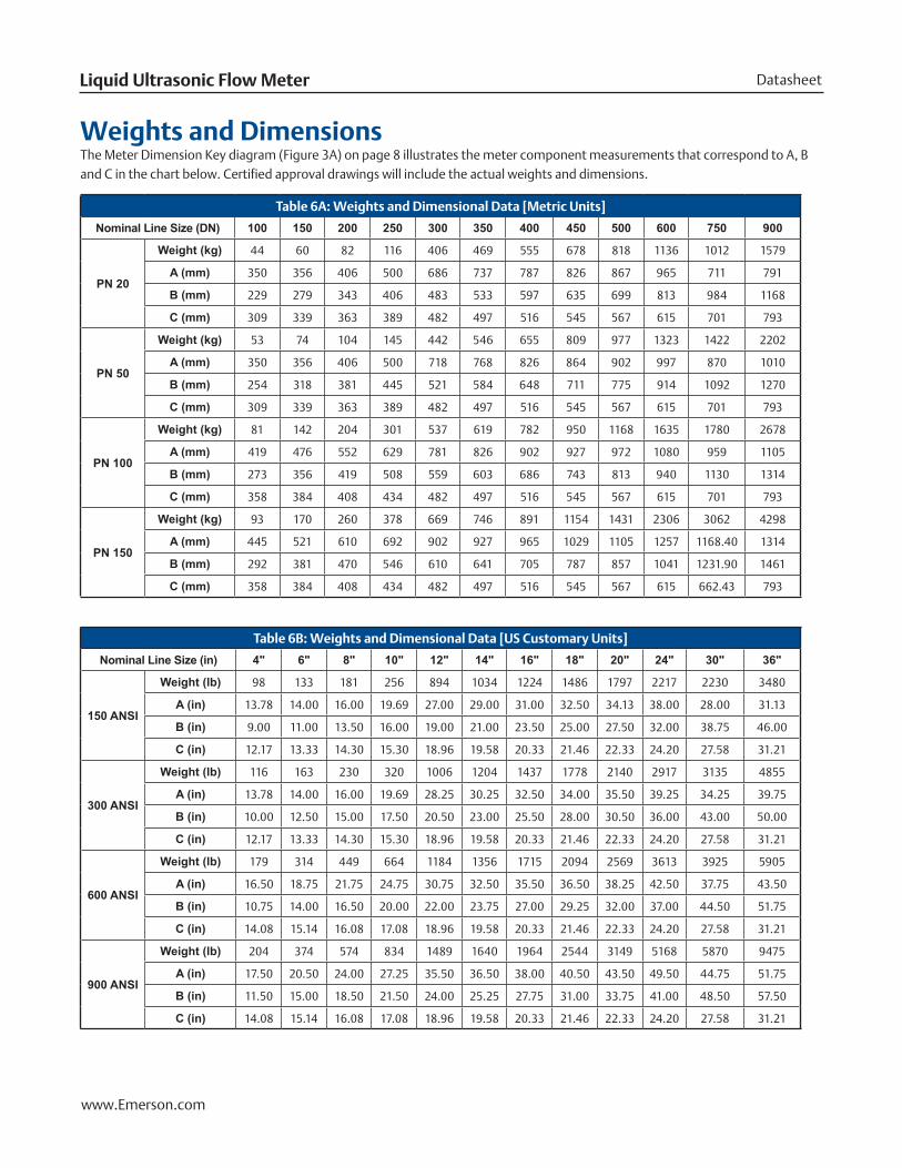
Table 6A: Weights and Dimensional Data [Metric Units]
Nominal Line Size (DN) 100 150 200 250 300 350 400 450 500 600 750 900
PN 20
Weight (kg) 44 60 82 116 406 469 555 678 818 1136 1012 1579
A (mm) 350 356 406 500 686 737 787 826 867 965 711 791
B (mm) 229 279 343 406 483 533 597 635 699 813 984 1168
C (mm) 309 339 363 389 482 497 516 545 567 615 701 793
PN 50
Weight (kg) 53 74 104 145 442 546 655 809 977 1323 1422 2202
A (mm) 350 356 406 500 718 768 826 864 902 997 870 1010
B (mm) 254 318 381 445 521 584 648 711 775 914 1092 1270
C (mm) 309 339 363 389 482 497 516 545 567 615 701 793
PN 100
Weight (kg) 81 142 204 301 537 619 782 950 1168 1635 1780 2678
A (mm) 419 476 552 629 781 826 902 927 972 1080 959 1105
B (mm) 273 356 419 508 559 603 686 743 813 940 1130 1314
C (mm) 358 384 408 434 482 497 516 545 567 615 701 793
PN 150
Weight (kg) 93 170 260 378 669 746 891 1154 1431 2306 3062 4298
A (mm) 445 521 610 692 902 927 965 1029 1105 1257 1168.40 1314
B (mm) 292 381 470 546 610 641 705 787 857 1041 1231.90 1461
C (mm) 358 384 408 434 482 497 516 545 567 615 662.43 793
Table 6B: Weights and Dimensional Data [US Customary Units]
Nominal Line Size (in) 4" 6" 8" 10" 12" 14" 16" 18" 20" 24" 30" 36"
150 ANSI
Weight (lb) 98 133 181 256 894 1034 1224 1486 1797 2217 2230 3480
A (in) 13.78 14.00 16.00 19.69 27.00 29.00 31.00 32.50 34.13 38.00 28.00 31.13
B (in) 9.00 11.00 13.50 16.00 19.00 21.00 23.50 25.00 27.50 32.00 38.75 46.00
C (in) 12.17 13.33 14.30 15.30 18.96 19.58 20.33 21.46 22.33 24.20 27.58 31.21
300 ANSI
Weight (lb) 116 163 230 320 1006 1204 1437 1778 2140 2917 3135 4855
A (in) 13.78 14.00 16.00 19.69 28.25 30.25 32.50 34.00 35.50 39.25 34.25 39.75
B (in) 10.00 12.50 15.00 17.50 20.50 23.00 25.50 28.00 30.50 36.00 43.00 50.00
C (in) 12.17 13.33 14.30 15.30 18.96 19.58 20.33 21.46 22.33 24.20 27.58 31.21
600 ANSI
Weight (lb) 179 314 449 664 1184 1356 1715 2094 2569 3613 3925 5905
A (in) 16.50 18.75 21.75 24.75 30.75 32.50 35.50 36.50 38.25 42.50 37.75 43.50
B (in) 10.75 14.00 16.50 20.00 22.00 23.75 27.00 29.25 32.00 37.00 44.50 51.75
C (in) 14.08 15.14 16.08 17.08 18.96 19.58 20.33 21.46 22.33 24.20 27.58 31.21
900 ANSI
Weight (lb) 204 374 574 834 1489 1640 1964 2544 3149 5168 5870 9475
A (in) 17.50 20.50 24.00 27.25 35.50 36.50 38.00 40.50 43.50 49.50 44.75 51.75
B (in) 11.50 15.00 18.50 21.50 24.00 25.25 27.75 31.00 33.75 41.00 48.50 57.50
C (in) 14.08 15.14 16.08 17.08 18.96 19.58 20.33 21.46 22.33 24.20 27.58 31.21
Weights and DimensionsThe Meter Dimension Key diagram (Figure 3A) on page 8 illustrates the meter component measurements that correspond to A, B and C in the chart below. Certified approval drawings will include the actual weights and dimensions.
March 2017Daniel 3812
www.Emerson.com
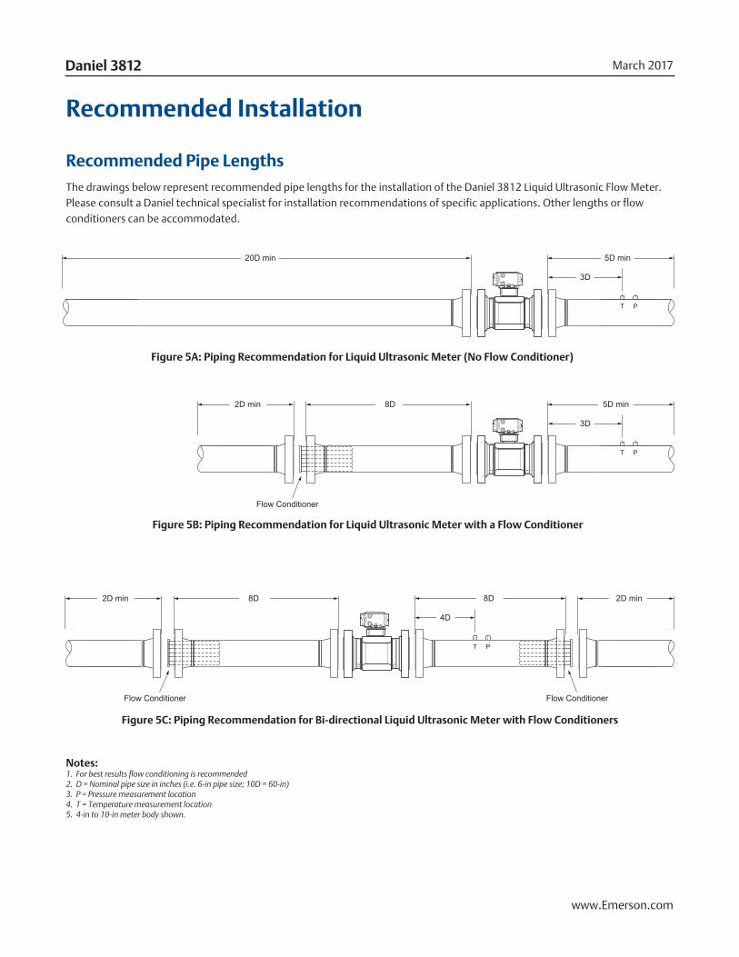
8D 8D
4D
2D min 2D min
Flow Conditioner Flow Conditioner
8D
3D
2D min 5D min
Flow Conditioner
3D
20D min 5D min
T P
T P
T P
T P
8D 8D
4D
2D min 2D min
Flow Conditioner Flow Conditioner
8D
3D
2D min 5D min
Flow Conditioner
3D
20D min 5D min
T P
T P
T P
T P
8D 8D
4D
2D min 2D min
Flow Conditioner Flow Conditioner
8D
3D
2D min 5D min
Flow Conditioner
3D
20D min 5D min
T P
T P
T P
T P
Notes: 1. For best results flow conditioning is recommended 2. D = Nominal pipe size in inches (i.e. 6-in pipe size; 10D = 60-in) 3. P = Pressure measurement location 4. T = Temperature measurement location5. 4-in to 10-in meter body shown.
Recommended Installation
Recommended Pipe LengthsThe drawings below represent recommended pipe lengths for the installation of the Daniel 3812 Liquid Ultrasonic Flow Meter. Please consult a Daniel technical specialist for installation recommendations of specific applications. Other lengths or flow conditioners can be accommodated.
Figure 5A: Piping Recommendation for Liquid Ultrasonic Meter (No Flow Conditioner)
Figure 5B: Piping Recommendation for Liquid Ultrasonic Meter with a Flow Conditioner
Figure 5C: Piping Recommendation for Bi-directional Liquid Ultrasonic Meter with Flow Conditioners
DatasheetLiquid Ultrasonic Flow Meter
www.Emerson.com
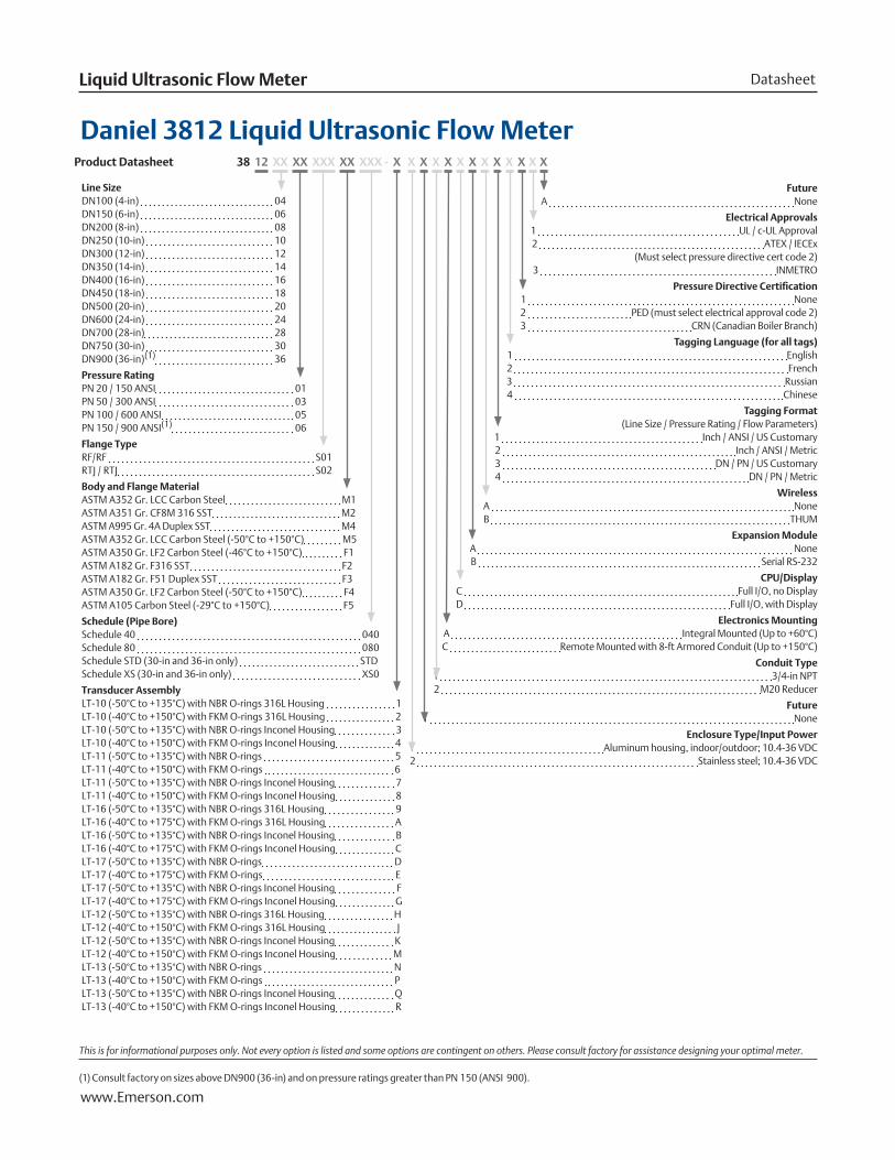
Line SizeDN100 (4-in) 04DN150 (6-in) 06 DN200 (8-in) 08DN250 (10-in) 10DN300 (12-in) 12DN350 (14-in) 14DN400 (16-in) 16DN450 (18-in) 18DN500 (20-in) 20DN600 (24-in) 24DN700 (28-in) 28 DN750 (30-in) 30DN900 (36-in)(1) 36
Pressure RatingPN 20 / 150 ANSI 01PN 50 / 300 ANSI 03PN 100 / 600 ANSI 05PN 150 / 900 ANSI(1) 06
Flange TypeRF/RF S01RTJ / RTJ S02
Body and Flange MaterialASTM A352 Gr. LCC Carbon Steel M1ASTM A351 Gr. CF8M 316 SST M2ASTM A995 Gr. 4A Duplex SST M4ASTM A352 Gr. LCC Carbon Steel (-50°C to +150°C) M5ASTM A350 Gr. LF2 Carbon Steel (-46°C to +150°C) F1ASTM A182 Gr. F316 SST F2ASTM A182 Gr. F51 Duplex SST F3ASTM A350 Gr. LF2 Carbon Steel (-50°C to +150°C) F4ASTM A105 Carbon Steel (-29°C to +150°C) F5
Schedule (Pipe Bore)Schedule 40 040Schedule 80 080Schedule STD (30-in and 36-in only) STDSchedule XS (30-in and 36-in only) XS0
Transducer AssemblyLT-10 (-50°C to +135°C) with NBR O-rings 316L Housing 1LT-10 (-40°C to +150°C) with FKM O-rings 316L Housing 2LT-10 (-50°C to +135°C) with NBR O-rings Inconel Housing 3LT-10 (-40°C to +150°C) with FKM O-rings Inconel Housing 4 LT-11 (-50°C to +135°C) with NBR O-rings 5LT-11 (-40°C to +150°C) with FKM O-rings 6LT-11 (-50°C to +135°C) with NBR O-rings Inconel Housing 7LT-11 (-40°C to +150°C) with FKM O-rings Inconel Housing 8LT-16 (-50°C to +135°C) with NBR O-rings 316L Housing 9LT-16 (-40°C to +175°C) with FKM O-rings 316L Housing ALT-16 (-50°C to +135°C) with NBR O-rings Inconel Housing BLT-16 (-40°C to +175°C) with FKM O-rings Inconel Housing CLT-17 (-50°C to +135°C) with NBR O-rings DLT-17 (-40°C to +175°C) with FKM O-rings ELT-17 (-50°C to +135°C) with NBR O-rings Inconel Housing FLT-17 (-40°C to +175°C) with FKM O-rings Inconel Housing GLT-12 (-50°C to +135°C) with NBR O-rings 316L Housing HLT-12 (-40°C to +150°C) with FKM O-rings 316L Housing JLT-12 (-50°C to +135°C) with NBR O-rings Inconel Housing KLT-12 (-40°C to +150°C) with FKM O-rings Inconel Housing MLT-13 (-50°C to +135°C) with NBR O-rings NLT-13 (-40°C to +150°C) with FKM O-rings PLT-13 (-50°C to +135°C) with NBR O-rings Inconel Housing QLT-13 (-40°C to +150°C) with FKM O-rings Inconel Housing R
FutureA None
Electrical Approvals1 UL / c-UL Approval2 ATEX / IECEx
(Must select pressure directive cert code 2)3 INMETRO
Pressure Directive Certification1 None2 PED (must select electrical approval code 2)3 CRN (Canadian Boiler Branch)
Tagging Language (for all tags)1 English2 French3 Russian4 Chinese
Tagging Format (Line Size / Pressure Rating / Flow Parameters)
1 Inch / ANSI / US Customary2 Inch / ANSI / Metric3 DN / PN / US Customary4 DN / PN / Metric
Wireless A NoneB THUM
Expansion ModuleA NoneB Serial RS-232
CPU/DisplayC Full I/O, no DisplayD Full I/O, with Display
Electronics MountingA Integral Mounted (Up to +60°C) C Remote Mounted with 8-ft Armored Conduit (Up to +150°C)
Conduit Type1 3/4-in NPT2 M20 Reducer
Future1 None
Enclosure Type/Input Power1 Aluminum housing, indoor/outdoor; 10.4-36 VDC2 Stainless steel; 10.4-36 VDC
Daniel 3812 Liquid Ultrasonic Flow MeterProduct Datasheet 38 12 XX XX XXX XX XXX - X X X X X X X X X X X X X
(1) Consult factory on sizes above DN900 (36-in) and on pressure ratings greater than PN 150 (ANSI 900).
This is for informational purposes only. Not every option is listed and some options are contingent on others. Please consult factory for assistance designing your optimal meter.
©2017 Emerson. All Rights Reserved. Unauthorized duplication in whole or in part is prohibited. Printed in the USA. DAN-LUSM-3812-DS-0317
The Emerson logo is a trademark and service mark of Emerson Electric Co. Daniel Measurement and Control, Inc. (“Daniel”) is an Emerson Automation Solutions business unit and a subsidiary of Daniel Industries, Inc. The Daniel name and logo are trademarks of Daniel Industries, Inc. All other trademarks are the property of their respective companies.
Emerson Automation Solutions
Daniel Measurement and Control, Inc. North America / Latin America: Headquarters USA - Houston, Texas T +1.713.467.6000 USA Toll Free 1.888.FLOW.001
www.Emerson.com/Daniel
Europe: Stirling, Scotland, UK T +44.1786.433400 Middle East, Africa: Dubai, UAE T +971.4.811.8100 Asia Pacific: Singapore T +65.6777.8211
Scan with your smart phone for more information