Embed Size (px)
Citation preview

43POLISH MARITIME RESEARCH, No 3/2011
INTRODUCTION
Crankshafts are applied everywhere it is necessary to convert reciprocating motion into rotational one or inversely. In engines and compressors they are commonly used.
Piston combustion engine in operation generates vibrations which result from occurrence of periodically varying gas and inertia forces. The forces generate the following kinds of vibrations:
• bending vibrations,• axial vibrations,• torsional vibrations.
The first two kinds of vibrations occurring in car combustion engines do not constitute any great danger for life time of their crankshafts but for ship large-power engines axial vibrations of crankshafts are a serious problem. Such vibrations cause that the entire system consisted of engine crankshaft, flywheel, shaft line and screw propeller displaces periodically along its axis. Axial vibration amplitude of the system practically depends on a design solution of screw propeller, namely, number of its blades.
However irrespective of an used dynamical engine operation system torsional vibrations are the most dangerous for its crankshaft. Out of many forces acting in the crankshaft-piston system the force T (Fig. 1) tangent to the circle described by crank, makes crankshaft rotating. The force T, one of two components of the force S acting along crankshaft axis, is that periodically changing [8, 9, 11, 12]. Its frequency for two-stroke engines is equal to 2π, and for four-stroke ones - to 4π. Changes
Wojciech Homik, Ph. D.Rzeszów University of Technology
Damping of torsional vibrations of ship engine crankshafts – general selection methods
of viscous vibration damper
ABSTRACT
This paper describes causes of torsional vibrations generated in ship engine crankshafts. Means for damping the torsional vibrations as well as general methods for selection of viscous torsional vibration dampers for a given type of engine are also presented. Exemplary results of calculations connected with selection of a viscous torsional vibration
damper intended for a six-cylinder engine, are attached.
Keywords: torsional vibrations; torsional vibration damping; torsional vibration dampers; crankshaft; natural vibration frequency
Fig. 1. Distribution of forces in crankshaft - piston system
POLISH MARITIME RESEARCH 3(70) 2011 Vol 18; pp. 43-4710.2478/v10012-011-0016-9

44 POLISH MARITIME RESEARCH, No 3/2011
of the force T generate accelerations of engine crankshaft rotational motion and in consequence torsional vibrations which change along with changing shaft line rotational speed. Worth mentioning that crankshaft deflection is limited only by shaft line torsional stiffness and torsional vibration amplitude can exceed its permissible values. In the case of lack of damping vibration run curve tends to infinity for any speed which generates a resonance harmonic.
Torsional damage of crankshaft, i.e. one of a changeable stiffness, takes place when the permissible amplitude value (permissible twist angle) φdop is exceeded (1) [2, 3].
(1)
where:Ms – torque,Li – reduced length of shaft segment,G – shear modulus,Ioi – polar moment of inertia.
Many formulae are used for calculating the reduced length of crankshaft, i.e. shaft segment between cylinder axes. Among the most known the following may be numbered:• Carter formula,• Ker Wilson formula,• Tulpin formula.
The formulae may be reduced to the general form as follows (2) [1, 2, 3, 8, 9]:
(2)
where:I – cross-section inertia moments,k – set of quantities which account for crank geometry,
and the indices stand for:cg – main journal,ck – crank journal,rw – crank arm,o – reduced value.
Importance of the problem in question, i.e. danger of shaft damage due to occurrence of torsional vibrations in propulsion systems of floating objects resulted in that Polish Register of Shipping (PRS) issued a specialty rule publication entirely devoted to the calculating of crankshafts of combustion-ignition engines [10]. One of its sections contains guidelines and conditions to be abide by crankshaft designers.
DAMPING OF TORSIONAL VIBRATIONS OF CRANKSHAFTS OF SHIP ENGINES
For many years for the damping of torsional vibrations of ship engine crankshafts the following kinds of dampers have been used:• frictional dampers,• rubber dampers (Photo 1),• viscous dampers (Photo 2),• spring dampers (Photo 3).
Among the above mentioned group of dampers the viscous one is most popular and successfully used for controlling vibration level of ship large-power medium-speed engines [4, 5].
GENERAL METHODS OF SELECTION AND DESIGN OF VISCOUS DAMPERS
OF TORSIONAL VIBRATIONS
In advance of commencing design of a viscous torsional vibration damper its designer should obtain, from engine producer, an appropriate set of necessary data [6].
The data should contain the information on: • kind of fuel (petrol, diesel oil),• number of cylinders,• type of engine (two-stroke, four-stroke),• minimum rotational speed of engine,• maximum rotational speed of engine,• range of operational speed of engine (if not constant),• ignition sequence,• main journal diameter,• crank journal diameter,• cylinder diameter,• mean indicated pressure,• total weight of masses in reciprocating axial motion,• torsional stiffness of shaft between cylinders,• permissible value of twist angle of shaft,• limitations for damper gabarites.
The above specified data make it possible to form, for real propulsion system, a substitute vibrating system which enables to calculate:- its natural frequency Ω [rad/s] (3),- resonance rotational speeds:
(3)
where:Ωw – natural vibration frequency of w-form,w – vibration form number,h – harmonic’s order; for two-stroke engines: h = 1, 2, 3, 4,…; for four-stroke engines: h = 0.5, 1, 1.5, 2, 2.5, 3, 3.5, 4…
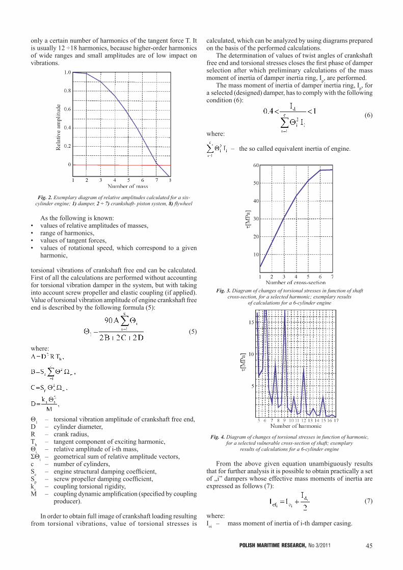
- relative torsional vibration amplitudes Θi of particular masses of the system (Fig. 2), as well as:
- range of harmonics in the area where calculations have to be performed (4):
(4)
For the so determined range of harmonics, values of the tangent force Th are calculated with accounting for the mean indicated pressure. Despite that the determined range of harmonics may be very wide it is sufficient, basing on multi-year experience, to take into account, in the performed analysis,
Photo 1 Photo 2 Photo 3
45POLISH MARITIME RESEARCH, No 3/2011
only a certain number of harmonics of the tangent force T. It is usually 12 ÷18 harmonics, because higher-order harmonics of wide ranges and small amplitudes are of low impact on vibrations.
Fig. 2. Exemplary diagram of relative amplitudes calculated for a six-cylinder engine; 1) damper, 2 ÷ 7) crankshaft- piston system, 8) flywheel
As the following is known:• values of relative amplitudes of masses,• range of harmonics,• values of tangent forces,• values of rotational speed, which correspond to a given
harmonic,
torsional vibrations of crankshaft free end can be calculated. First of all the calculations are performed without accounting for torsional vibration damper in the system, but with taking into account screw propeller and elastic coupling (if applied). Value of torsional vibration amplitude of engine crankshaft free end is described by the following formula (5):
(5)
where:
Θ1 – torsional vibration amplitude of crankshaft free end,D – cylinder diameter,R – crank radius,Th – tangent component of exciting harmonic,Θi – relative amplitude of i-th mass,ΣΘi – geometrical sum of relative amplitude vectors,c – number of cylinders,Se – engine structural damping coefficient,Sp – screw propeller damping coefficient,ks – coupling torsional rigidity,M – coupling dynamic amplification (specified by coupling
producer).
In order to obtain full image of crankshaft loading resulting from torsional vibrations, value of torsional stresses is
calculated, which can be analyzed by using diagrams prepared on the basis of the performed calculations.
The determination of values of twist angles of crankshaft free end and torsional stresses closes the first phase of damper selection after which preliminary calculations of the mass moment of inertia of damper inertia ring, Ip, are performed.
The mass moment of inertia of damper inertia ring, Ip, for a selected (designed) damper, has to comply with the following condition (6):
(6)
where:
– the so called equivalent inertia of engine.
Fig. 3. Diagram of changes of torsional stresses in function of shaft cross-section, for a selected harmonic; exemplary results
of calculations for a 6-cylinder engine
Fig. 4. Diagram of changes of torsional stresses in function of harmonic, for a selected vulnerable cross-section of shaft; exemplary
results of calculations for a 6-cylinder engine
From the above given equation unambiguously results that for further analysis it is possible to obtain practically a set of „i” dampers whose effective mass moments of inertia are expressed as follows (7):
(7)
where:Ioi – mass moment of inertia of i-th damper casing.

46 POLISH MARITIME RESEARCH, No 3/2011
Now, having the preliminarily selected set of „i” dampers, oneperforms identical calculations as for the system without damper but extended by the effective mass moment of inertia Iefi.
For every i-th system equipped with i-th damper the following is determined:• system natural frequency,• range of harmonics, • resonance speeds,• values of relative amplitudes (Fig. 5),• values of twist angles of crankshaft free end,• values of torsional stresses (Fig. 6).
Comparative analysis of the obtained results makes it possible to select, from the set of „i” dampers, that most effective in a given dynamic system.
Fig. 5. Diagrams of relative amplitudes of particular equivalent systems for the whole set of preliminarily selected dampers; exemplary results
of calculations for a 6-cylinder engine
Fig. 6. Diagrams of torsional stresses in function of the most loaded cross-sections of shaft for the whole set of preliminarily selected dampers;
exemplary results of calculations for a 6-cylinder engine
Viscous torsional vibration damper is that to which the fluid friction phenomenon is applied to effect vibration damping [7]. Therefore also value of friction moment resulting from friction forces acting on working surfaces of damper ring and casing, decides on its effectiveness.
The total value of friction moment which appears on damper inertia ring may be expressed as follows (8):
Mtp = Mtpz + Mtpw + Mtpb (8)
and, that of friction moment on working surfaces of damper casing (9):
Mto = Mtoz + Mtow + Mtob (9)
where:Mt – friction moment,
and the indices stand for: p – ring,o – casing,z – outer surface,w – inner surface,b – side surface.
Value of the friction moment does not depend only and solely on the geometrical parameters of damper but also on the fluid kinematic viscosity (10):
(10)
where:η – dynamic fluid viscosity,ρ – fluid density.
During selection of fluid viscosity intended for damper it should be remembered that the viscosity changes along with temperature changing.
As already mentioned, the vibration damping in the designed device is effected due to friction, hence energy dissipated by damper is transformed into heat. The heat generated in damper during the initial phase of its work is transferred mainly to the environment and partly used for heating the damper. It so long proceeds until the damper obtains the so-called saturation temperature.
After reaching the saturation temperature by the damper a justified concern arises that it may become seized due to its overheating resulting not only from the transformation of dissipated energy into heat but also its operation in an elevated environmental temperature (operation of damper in engine chamber) (Photo 4).
Photo 4. Image of an overheated and seized viscous torsional vibration damper, acc. tests made by the DAMPOL
In practice the detrimental phenomenon makes that the damper, instead to damp vibrations, starts to excite them. The damper, if correctly designed, should operate reliably for 20000 ÷ 30000 h in negative temperatures and first of all higher temperatures even as high as 120°C. Laboratory tests performed on viscous torsional vibration dampers demonstrated that events of seizing the dampers occurred when their working temperature values exceeded by 60°C the temperature for which they were designed.
Satisfactory effects of damper operation are reached when it operates within the temperature range from 75° ÷ 90°C in continuous cycle of work.

47POLISH MARITIME RESEARCH, No 3/2011
In view of damper operation effectiveness it is recommended to keep the specific power dissipated by damper lower than 8.6 [KM/m2] (counted per total surface area of its inertia member).
The range of heat flow within damper depends on:• working conditions (a.o. engine rotational speed)• damper size, • damper design (of screw bolted casing or cold shut one)and is expressed as follows (11):
H = h · Ap (11)
where:H – permissible heat flow rate [J/h],Ap – total surface area of inertia member,h = 18 ÷ 22 [MJ/m2/h] – for instantaneous operation at critical
speed,h = 9 ÷ 11 [MJ/m2/h] – for dampers used for small high-speed
engines intended for continuous operation at critical speeds, such as those applied to cars,
h = 4.5 ÷ 5.5 [MJ/m2/h] – for dampers of large low-speed engines intended for continuous operation at critical speeds, such as those used in ships.
Note: The paper has been financially supported by the National Science Centre - Research Project No N N509 547440.
BIBLIOGRAPHY
1. Brun R.: High-speed combustion-ignition engines (in Polish). WKiŁ (Transport and Communication Publishers), 1973
2. Dąbrowski Z.: Machine shafts (in Polish). PWN (State Scientific Publishers), 1999
3. Dąbrowski Z. Maksymiuk M.: Shafts and axles (in Polish). PWN, 1984
4. Homik W.: Diagnostics, maintenance and regeneration of torsional vibration dampers for crankshafts of ship diesel engines. Polish Maritime Research, No 1/2010
5. Homik W.: Assessment criteria of merits of viscous torsional vibration damper for combustion engine crankshaft.Western Scientific Centre of Ukrainian Transport Academy - Transportna Akademia Ukraini. Praci Zachodnowo Naukowo Centrum, NR 19 str 90-94, 2009,
6. Homik W.: Designing viscous torsional vibration dampers (in Polish). Przegląd Mechaniczny No.10/2007
7. Homik. W.: Torsional vibrations of crankshaft of engine without damper and that fitted with viscous torsional vibration damper (in Polish). Przegląd Mechaniczny No. 9/2008
8. Jędrzejowski J.: Mechanics of car engine crank systems (in Polish). WKiŁ, 1986
9. Niewiarowski K.: Piston combustion engines (in Polish). WKiŁ, 1973
10. Polish Register of Shipping: Calculation of crankshafts of compression-ignition engines (in Polish). Publication No. 8/P, Gdańsk, 2007
11. Wajand J. A., Wajand J. T.: Medium - and high - speed piston combustion engines (in Polish). PWN, 1984
12. Wajand J.A.: Self ignition engines (in Polish). WKiŁ, 1973.
CONTACT WITH THE AUTHORWojciech Homik, Ph. D.
Rzeszów University of TechnologyThe Faculty of Mechanical Engineering and Aeronautics
Al. Powstańców Warszawy 8, 35-959 Rzeszów, POLAND
tel.: 17 865 1100 w 1637, 17 865 1637e-mail: [email protected]: [email protected]