Embed Size (px)
Citation preview
DAMPING OF COMPOSITE MATERIAL
STRUCTURES WITH RIVETED JOINTS
A thesis submitted in partial fulfillment of the requirements for a degree of
Bachelor of Technology
in
Mechanical Engineering
by
NIKHIL CHINTHAPATLA
Roll No. : 108ME053
Department of Mechanical Engineering
National Institute of Technology, Rourkela
2012
ii
DAMPING OF COMPOSITE MATERIAL
STRUCTURES WITH RIVETED JOINTS
A thesis submitted in partial fulfillment of the requirements for a degree of
Bachelor of Technology
in
Mechanical Engineering
by
NIKHIL CHINTHAPATLA
Roll No. : 108ME053
Under the guidance of
Prof. B. K. NANDA
Department of Mechanical Engineering
National Institute of Technology, Rourkela
2012

iii
National Institute of Technology
Rourkela
CERTIFICATE
This is to certify that the thesis entitled “DAMPING OF COMPOSITE MATERIAL
STRUCTURES WITH RIVETED JOINTS” submitted by Mr. NIKHIL
CHINTHAPATLA in partial fulfillment of the requirements for the award of
Bachelor of Technology Degree in Mechanical Engineering at National Institute
of Technology, Rourkela (Deemed University) is an authentic work carried out
by him under my guidance.
To the best of my knowledge the matter embodied in the thesis has not been
submitted to any University/Institute for the award of any Degree or Diploma
Prof. B.K. NANDA
Department of Mechanical Engineering
National Institute of Technology
Rourkela – 769008 DATE:
iv
ACKNOWLEDGEMENT
I express my deep sense of gratitude and reverence to my thesis supervisor Prof. B. K.
Nanda, Professor, Mechanical Engineering Department, National Institute of Technology,
Rourkela, for his invaluable encouragement, helpful suggestions and supervision throughout
the course of this work and providing valuable department facilities.
I would like to thank Prof. K. P. Maity, Head of the Department, Prof. C. K. Biswas,
Chairman of Production Engineering, Prof. S. K. Sahoo and Prof. R. K. Behera, faculty
Adviser.
DATE: NIKHIL CHINTHAPATLA
108ME053
v
ABSTRACT
Vibration and noise reduction are crucial in maintaining high performance level and
prolonging the useful life of machinery, automobiles, aerodynamic and spacecraft structures.
It is observed that damping in materials occur due to energy release due to micro-slips along
frictional interfaces and due to varying strain regions and interaction between the metals. But
it was found that the damping effect in metals is quite small that it can be neglected. Damping
in metals is due to the micro-slips along frictional interfaces. Composites, however, have
better damping properties than structural metals and cannot be neglected. Typically, the
range of composite damping begins where the best damped metal stops.
In the present work, theoretical analysis was done on various polymer matrix composite
(glass fibre polyesters) with riveted joints by varying initial conditions. Strain energy loss
was calculated to calculate the damping in composites. Using FEA model, load variation w.r.t
time was observed and the strain energy loss calculated was utilised in finding the material
damping for Carbon fibre epoxy with riveted joints. Various simulations were performed in
ANSYS and these results were utilised to calculate the loss factor, Rayleigh‘s damping
constants and logarithmic decrement.
These results can be used in designing machine tools, aircrafts, spacecraft‘s, satellites, missile
systems and automobiles effectively to maximise the damping capacity and to improve their
performances and the product life.
vi
CONTENTS
01. COVER PAGES i - iii
02. ACKNOWLEDGEMENT iv
03. ABSTRACT v
04. LIST OF TABLES AND FIGURES vii
05. INTRODUCTION 01
1.1 BACKGROUND 1.2 OBJECTIVE OF THE WORK
06. LITERATURE REVIEW 03 2.1 INTRODUCTION 2.2 OVERVIEW ON DAMPING
2.3 PAST RESEARCH ON DAMPING
07. COMPOSITES 07
08. DAMPING 09
4.1 DEFINITON OF DAMPING 4.2 TYPES OF DAMPING 4.2.1 MATERIAL DAMPING
4.2.1.1 ENERGY BALANCE APPROACH 4.2.2 FLUID DAMPING
4.2.3 STRUCTURAL DAMPING 4.3 DAMPING MECHANISM IN COMPOSITE MATERIALS
09. VISCO ELASTIC DAMPING 15 5.1 FACTORS AFFECTING VISCO ELASTIC DAMPING 5.2 MATERIALS UTILISED
10. MATHEMATICAL MODELLING 17
6.1 STRUCTURAL DAMPING FACTOR
6.2 COMPLEX STIFFNESS
11. MODELLING AND ANALYSIS OF COMPOSITES WITH RIVETS 19
7.1 MODELLING 7.2 ANALYSIS OF MODEL IN ANSYS 7.2.1 GENERAL OVERVIEW OF DAMPING IN ANSYS
7.2.2 RAYLEIGH DAMPING
12. FINITE ELEMENTAL ANALYSIS 23
8.1 MODAL ANALYSIS 8.2 HARMONIC RESPONSE ANALYSIS
8.3 TRANSIENT DYNAMIC ANALYSIS
13. RESULTS AND CONCLUSION 29
14. REFERENCES 30
vii
LIST OF TABLES AND FIGURES
TABLES:
01. PROPERTIES OF CARBON-FIBRE EPOXY COMPOSITE 16
02. FREQUENCY OUTPUT OF MODAL ANALYSIS 24
03. MAXIMUM AND MINIMUM OF DEFORMATION WITH TIME 27
FIGURES:
01. (Fig 3.1) TYPES OF FIBRE REINFORCED MATERIALS 07
02. (Fig 4.1) MASS-SPRING DAMPER SYSTEM 09
03. (Fig 4.2) RVE MODEL 11
04. (Fig 7.1) MODEL DESIGNED ON CATIA V5R17 19
05. (Fig 7.2) VARIOUS VIEWS OF DRAFTING 19
06. (Fig 7.3) RAYLEIGH DAMPING 22
07. (Fig 8.1) ANSYS MODEL 23
08. (Fig 8.2) MODE Vs. FREQUENCY GRAPH 24
09. (Fig 8.3) MODAL ANALYSIS 25
10. (Fig 8.4) HARMONIC RESPONSE ANALYSIS 25
11. (Fig 8.5) AMPLITUDE Vs. FREQUENCY GRAPH 26
12. (Fig 8.6) PHASE ANGLE Vs. FREQUENCY GRAPH 26
13. (Fig 8.7) MAXIMUM DEFORMATION Vs. TIME GRAPH 28
14. (Fig 8.8) MINIMUM DEFORMATION Vs. TIME GRAPH 28

Page | 1
CHAPTER 1
INTRODUCTION
1.1 BACKGROUND
Damping capacity is an extent of a material's ability to dissipate elastic-strain energy during
mechanical vibration or wave propagation. Complications involving vibration arise in many
regions of mechanical, civil and aerospace engineering. The damping of a structural
component or element is often a significantly overlooked criterion for good mechanical
design. Numerous mechanical failures over a seemingly infinite multitude of structures
occurred due to lack of damping in structural elements. For accounting the damping effects in
a structural material, lots of researches and studies have been done in the field to suppress the
vibration and to minimize the mechanical failures.
Since it was found that damping materials can be utilised in treatment in passive damping
technology to mechanical components and structures to increase the damping performance,
there had been a commotion on the on-going research and studies over the last few periods to
either alter the existing materials and components, or to develop an entirely new type of
material to improve the structural dynamics of components for which damping concept could
be applied. Composite structures are generally polymers, which give various ranges of
different compositions which result in different material properties as well as behaviour.
Hence, composite damping structures and materials can be developed and tailored quite
efficiently for a specific purpose and application.
Problems involving vibration and damping occur in many regions of mechanical, civil and
aerospace engineering. Engineering composite structures and materials are generally
fabricated using a variety of connections which include bolted, riveted, welded and bonded
joints etc. The dynamics of mechanical joints is a topic of special importance due to their
strong effect on the performance of the structural material. Moreover, the inclusion of the
Page | 2
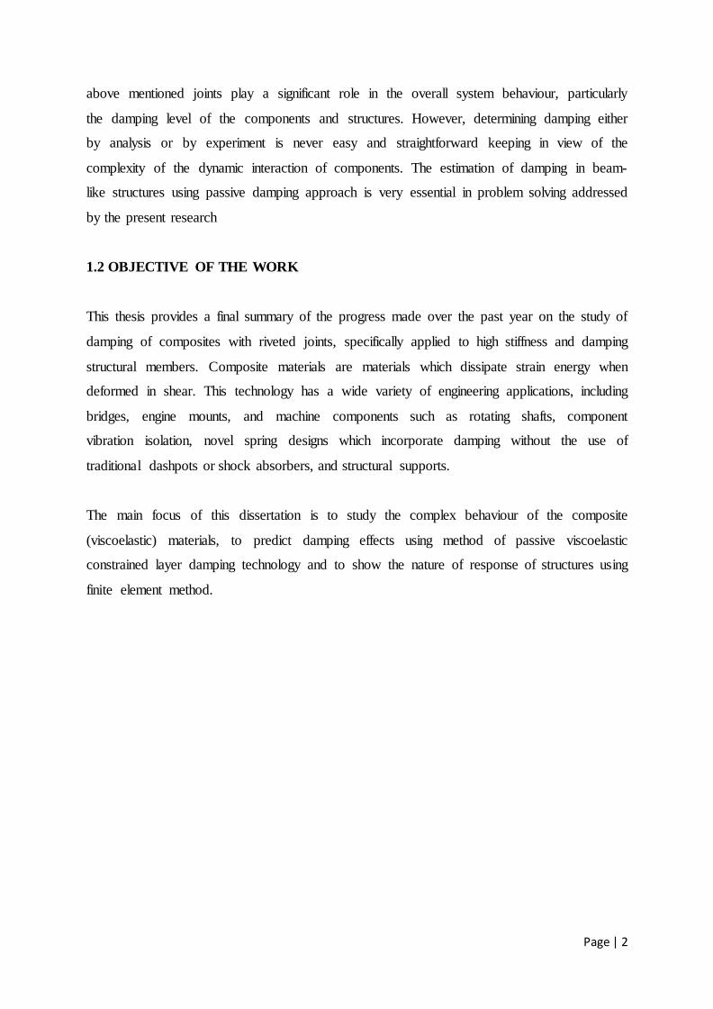
above mentioned joints play a significant role in the overall system behaviour, particularly
the damping level of the components and structures. However, determining damping either
by analysis or by experiment is never easy and straightforward keeping in view of the
complexity of the dynamic interaction of components. The estimation of damping in beam-
like structures using passive damping approach is very essential in problem solving addressed
by the present research
1.2 OBJECTIVE OF THE WORK
This thesis provides a final summary of the progress made over the past year on the study of
damping of composites with riveted joints, specifically applied to high stiffness and damping
structural members. Composite materials are materials which dissipate strain energy when
deformed in shear. This technology has a wide variety of engineering applications, including
bridges, engine mounts, and machine components such as rotating shafts, component
vibration isolation, novel spring designs which incorporate damping without the use of
traditional dashpots or shock absorbers, and structural supports.
The main focus of this dissertation is to study the complex behaviour of the composite
(viscoelastic) materials, to predict damping effects using method of passive viscoelastic
constrained layer damping technology and to show the nature of response of structures using
finite element method.
Page | 3
CHAPTER 2
LITERATURE REVIEW
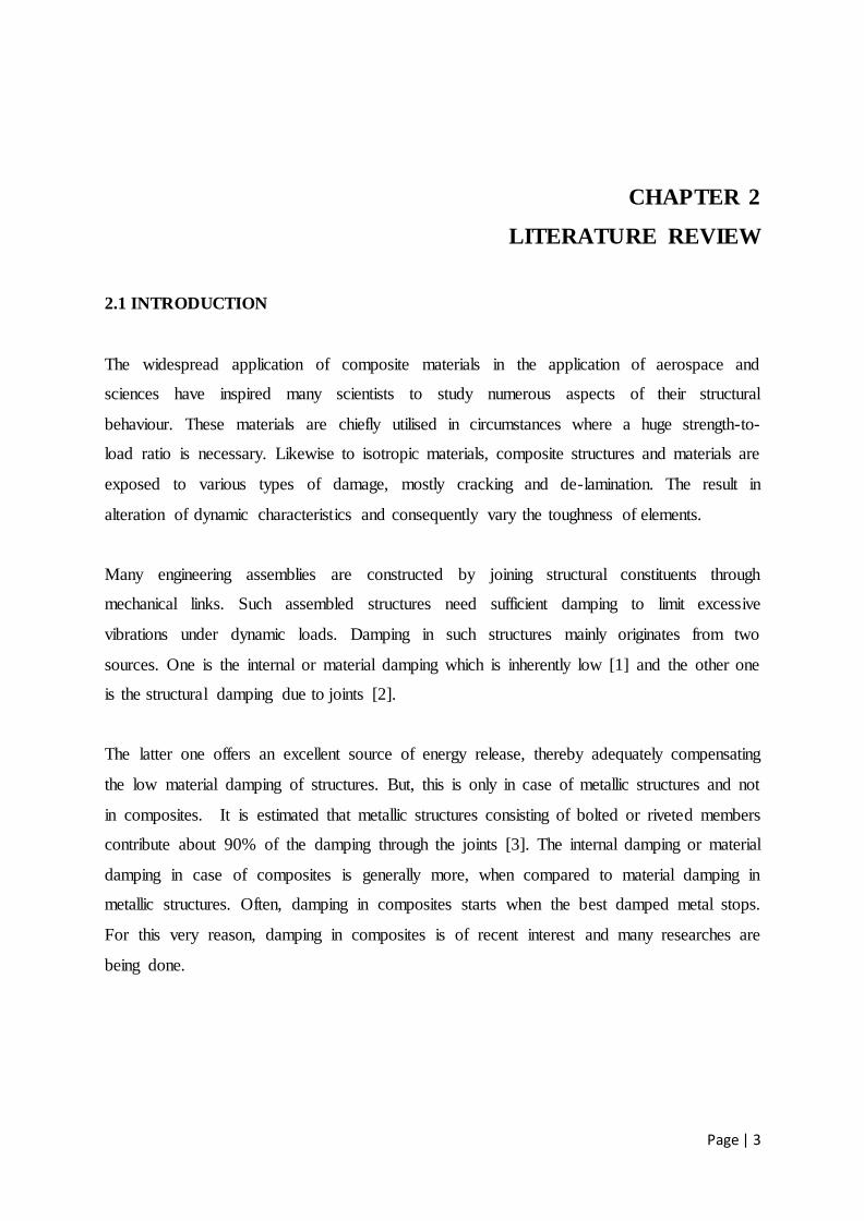
2.1 INTRODUCTION
The widespread application of composite materials in the application of aerospace and
sciences have inspired many scientists to study numerous aspects of their structural
behaviour. These materials are chiefly utilised in circumstances where a huge strength-to-
load ratio is necessary. Likewise to isotropic materials, composite structures and materials are
exposed to various types of damage, mostly cracking and de-lamination. The result in
alteration of dynamic characteristics and consequently vary the toughness of elements.
Many engineering assemblies are constructed by joining structural constituents through
mechanical links. Such assembled structures need sufficient damping to limit excessive
vibrations under dynamic loads. Damping in such structures mainly originates from two
sources. One is the internal or material damping which is inherently low [1] and the other one
is the structural damping due to joints [2].
The latter one offers an excellent source of energy release, thereby adequately compensating
the low material damping of structures. But, this is only in case of metallic structures and not
in composites. It is estimated that metallic structures consisting of bolted or riveted members
contribute about 90% of the damping through the joints [3]. The internal damping or material
damping in case of composites is generally more, when compared to material damping in
metallic structures. Often, damping in composites starts when the best damped metal stops.
For this very reason, damping in composites is of recent interest and many researches are
being done.
Page | 4
2.2 OVERVIEW ON DAMPING
The 3 crucial factors that determine the dynamic responses of a structural material and its
noise propagation features are mass, rigidity and damping. Mass and rigidity are associated
with storage of energy. Damping results in the release of energy by a vibration system. For a
linear system, when the forcing frequency is the equal to the natural frequency of the system,
the response is very huge and can easily cause hazardous consequences. In the frequency
domain, the response near the natural frequency is "controlled damping". Larger damping can
help to decrease the amplitude of resonating structures. Increased damping also results in
faster deterioration of free vibration, reduced dynamic stresses, smaller structural response to
noise and sound, and increased noise propagation loss above the threshold frequency. A lot of
literatures have been published on damping due to vibration. ASME published a collection of
papers on structural damping in 1959 [6]. Lazan's book published in 1968 gave a very good
idea on damping research work, discussed different mechanisms and forms of damping, and
studied damping at both the microscopic and macroscopic levels [7]. Lazan conducted
comprehensive studies into the general nature of material damping and presented damping
results data for almost 2000 materials and test conditions. Lazan's results show that the
logarithmic decrement values increase with dynamic stress, i.e., with vibration amplitude,
where material damping is the dominant mechanism. This book is also valuable as a
handbook because it contains more than 50 pages of data on damping properties of various
materials, including metals, alloys polymers, composites, glass, stone, natural crystals,
particle-type materials, and fluids. About 20 years later, Nashif, Jones and Henderson
published another comprehensive book on vibration damping [8]. Jones himself wrote a
handbook especially on viscoelastic damping 15 years later [9]. Sun and Lu's book published
in 1995 presents recent research accomplishments on vibration damping in beams, plates,
rings, and shells [10]. Finite element models on damping treatment are also summarized in
this book. There is also other good literature available on vibration damping [11-
13].Damping in vibrating mechanical systems has been subdivided into two classes: Material
damping and system damping, depending on the main routes of energy release. Coulomb
(1784) postulated that material damping arises due to interfacial friction between the grain
boundaries of the material under dynamic condition. Further studies on material damping
have been made by Robertson and Yorgiadis (1946), Demer (1956), Lazan (1968) and
Birchak (1977). System damping arises from slip and other boundary shear effects at mating
surfaces, interfaces or joints between distinguishable parts. Murty (1971) established that the
Page | 5
energy released at the support is very small compared to material damping.
2.3 REVIEW OF PAST RESEARCH ON DAMPING OF COMPOSITE MATERIALS
Bert [14] and Nashif et al.[15] had done survey on the damping capacity of fibre reinforced
composites and found out that composite materials generally exhibit higher damping than
structural metallic materials. Chandra et al. [16] has done research on damping in fibre-
reinforced composite materials.
Composite damping mechanisms and methodology applicable to damping analysis is
described and had presented damping studies involving macro-mechanical, micromechanical
and Viscoelastic approaches. Gibson et al.[17] and Sun et al.[18,19] assumed viscoelasticity
to describe the behaviour of material damping of composites.
The concept of specific damping capacity (SDC) was adopted in the damped vibration
analysis by Adams and his co-workers [20-21], Morison [22] and Kinra et al [23].
The concept of damping in terms of strain energy was apparently first introduced by Ungar
et.al [24] and was later applied to finite element analysis by Johnson et.al [25]. Gibson et.al
[26] has developed a technique for measuring material damping in specimens under forced
flexural vibration. Suarez et al [27] has utilised Random and Impulse Techniques for
Measurement of Damping in Composite Materials. The random and impulse techniques
utilize the frequency-domain transfer function of a material specimen under random and
impulsive excitation. Gibson et al [28] utilised the modal vibration response measurements to
characterize, quickly and accurately the mechanical properties of fibre-reinforced composite
materials and structures.
Lin et al. [29] predicted SDC in composites under flexural vibration using finite element
method based on modal strain energy (MSE) method considering only two inter laminar
stresses and neglecting transverse stress.
Koo KN et al. [30] studied the effects of transverse shear deformation on the modal loss
factors as well as the natural frequencies of composite laminated plates by using the finite
element method based on the shear deformable plate theory.
Page | 6
SINGH S. P et al. [31] analysed damped free vibrations of composite shells using a first order
shear deformation theory in which one assumes a uniform distribution of the transverse shear
across the thickness, compensated with a correction factor.
Polymeric materials are widely utilised for sound and vibration damping. One of the more
notable properties of these materials, besides the high damping ability, is the strong
frequency dependence of dynamic properties; both the dynamic modulus of elasticity and the
damping characterized by the loss factor [30-35].
Mycklestad [32] was one of the pioneering scientists into the investigation of complex
modulus behaviour of viscoelastic materials (Jones, 2001, Sun, 1995). Viscoelastic material
properties are generally modelled in the complex domain because of the nature of visco-
elasticity. Viscoelastic materials possess both elastic and viscous properties. The typical
behaviour is that the dynamic modulus increases monotonically with the increase of
frequency and the loss factor exhibits a wide peak [8, 33].
It is rare that the loss factor peak, plotted against logarithmic frequency, is symmetrical with
respect to the peak maximum, especially if a wide frequency range is considered. The
experiments usually reveal that the peak broadens at high frequencies. In addition to this, the
experimental data on some polymeric damping materials at very high frequencies, far from
the peak centre, show that the loss factor–frequency curve ‗‗flattens‘‘ and seems to approach
a limit value, while the dynamic modulus exhibits a weak monotonic increase at these
frequencies [34-38]. These phenomena can be seen in the experimental data published by
Madigosky and Lee [34], Rogers [35] and Capps [36] for polyurethanes, and moreover by
Fowler [37], Nashif and Lewis [38] for other polymeric damping materials.
The computerized methods of acoustical and vibration calculus require the mathematical
form of frequency dependences of dynamic properties. A reasonable method of describing
the frequency dependences is to find a good material model fitting the experimental data.
Page | 7
CHAPTER 3
COMPOSITES
Composite materials are naturally occurring materials or synthetically prepared from 2 or
more constituent materials with considerably different physical or chemical properties or both
which remain isolated and dissimilar at the macroscopic or microscopic scale within the
completed structure. The elements are assorted in such a way so that they can retain their
distinctive physical state and which are not solvable with each other nor a new chemical
compound is formed. One element is known as reinforcing state which is embedded in
another phase called matrix. The most visible applications are pavement in roadways in the
form of either steel and aggregate reinforced Portland cement or asphalt concrete.
Most of the fibres are utilised as the reinforcing state and are even tougher than the matrix
and this matrix is utilised in holding the fibres intact. Examples: Aluminium‘s matrix
implanted in boron fibres and an epoxy matrix implanted with glass or carbon fibres. These
fibres may be long or short, directionally aligned or randomly orientated, or some sort of
mixture, depending on the intended use of the material. Commonly utilised materials for the
matrix are polymers, metals, ceramics, carbon and fibres are carbon (graphite) fibres, aramid
fibres and boron fibres.
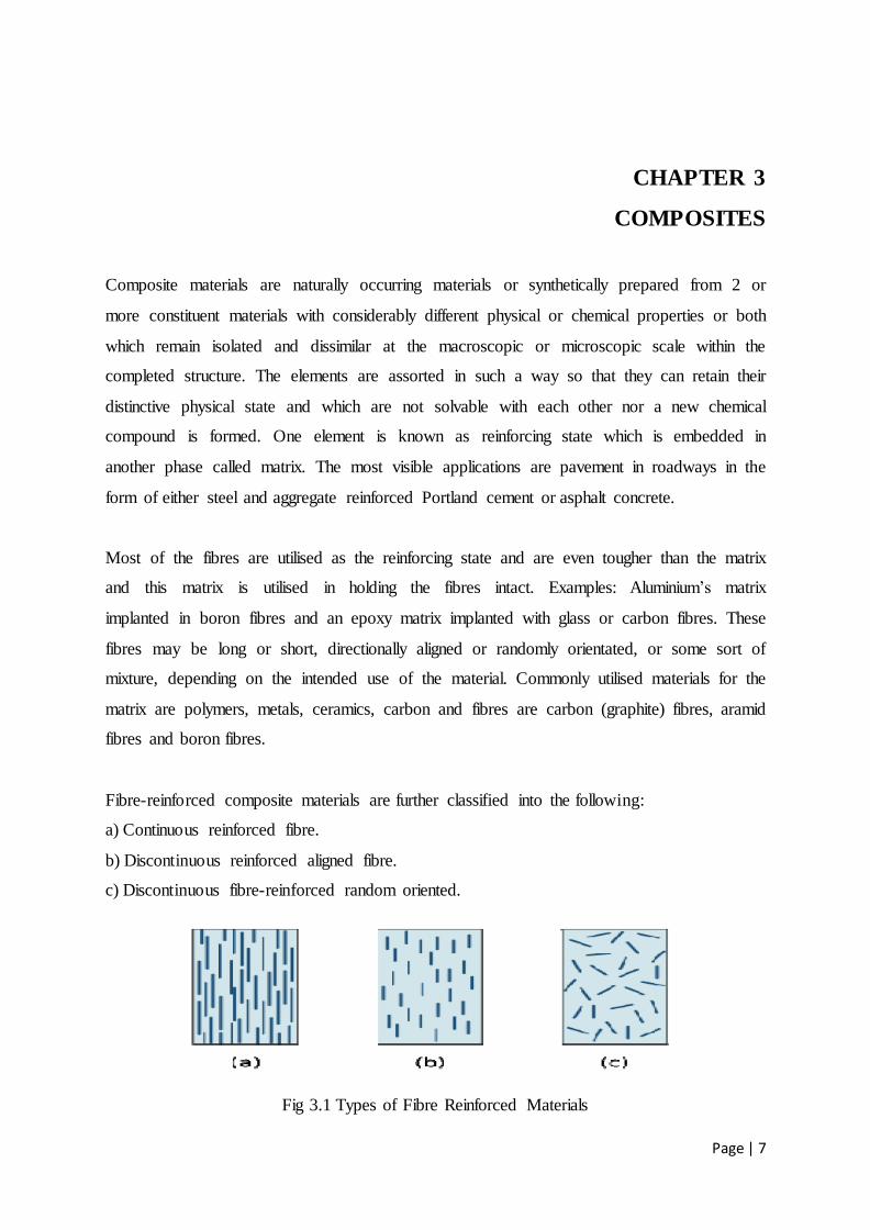
Fibre-reinforced composite materials are further classified into the following:
a) Continuous reinforced fibre.
b) Discontinuous reinforced aligned fibre.
c) Discontinuous fibre-reinforced random oriented.
Fig 3.1 Types of Fibre Reinforced Materials
Page | 8
Composites utilised in this work are Carbon epoxy fibre.
Carbon fibre is made up of extremely thin fibres of carbon. It is utilised as an reinforcing
agent for many polymer products; the resulting composite material is commonly known as
Carbon fibre epoxy. Uses for regular carbon-fibre include applications in the fields of
automotive engineering and also aerospace engineering, like Formula One. The toughest and
most costly of these essences, carbon nanotubes, are enclosed in some principally polymer
baseball bats, car parts and also golf clubs where economically they are available.
Epoxy is a polymer used for thermosetting which is formed by reaction of an epoxide "resin"
with polyamine "hardener". Epoxy has a widespread variety of applications, including fibre-
reinforced plastic materials and universal purpose adhesives. The uses for epoxy materials are
for outer layers which include adhesives, coatings and materials using such composite as
those using carbon fibre and fibreglass reinforcements (although polyester, vinyl ester, and
other thermosetting resins are generally utilised for glass-reinforced plastic).
The damping rising due to the interactions in-between fibres and matrix can be very huge and
are very complex in nature because of many properties of composites which affect the
interactions. For example, length, fibre orientation, and interface all affect the damping
properties. But the effect of length on damping can be neglected, since it is very small.
Damping is generally more when the orientation of fibres is off the axis by 5 to 30 degrees.
Page | 9
CHAPTER 4
DAMPING
4.1 DEFINITION OF DAMPING
In physics, damping is a phenomenon in which the amplitude of an oscillation tends to reduce
after every cycle in an oscillatory motion, particularly in case of harmonic oscillator. Friction
is generally considered as one such damping effect. In engineering terms, damping can be
mathematically modelled as any force which is in sync with the velocity of object and
opposite in direction to it. If such a force is proportional to the speed or velocity, as for a
simple mechanical gelatinous damper, the force F may be related to the velocity v given by
F= -cv, where c is the viscous damping coefficient (N-s/m).
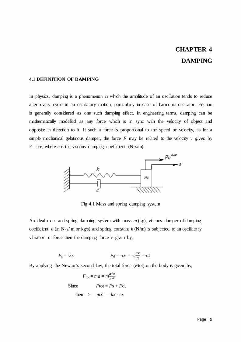
Fig 4.1 Mass and spring damping system
An ideal mass and spring damping system with mass m (kg), viscous damper of damping
coefficient c (in N-s/ m or kg/s) and spring constant k (N/m) is subjected to an oscillatory
vibration or force then the damping force is given by,
Fs = -kx Fd = -cv = -c
=-cẋ
By applying the Newton's second law, the total force (Ftot) on the body is given by,
Ftot = ma = m
Since Ftot = Fs + Fd,
then => m = -kx - cẋ

Page | 10
This differential equation can be rearranged as:
+ ẋ +
,
δ =
√ ω0=√
.
where ωo, is the un-damped natural frequency of the vibratory system and δ, is known as the
damping ratio of the spring.
Depending upon the value of δ, the motion of mass shown in the above Figure can be divided
into the following three cases given below:
(1) Oscillatory motion when 0.1<δ;
(2) Non Oscillatory motion when 0.1>δ and
(3) Critical damped motion when 0.1=δ. In last case, the general solution of the system is
Viscous damping can be utilised whatever may be the form of the excitation. The viscous
damping is the Rayleigh-type damping given by
4.2 TYPES OF DAMPING
Three main types of damping are present in any mechanical system:
1) Internal damping (Damping due to material properties)
2) Structural damping (Damping at joints and interfaces)
3) Fluid damping (Damping through fluid and structure interactions)
4.2.1 MATERIAL (Internal) DAMPING
Material or internal damping of materials generally originates from the energy release
associated with microstructure defects, such as grain boundaries and impurities; thermo
elastic properties and effects can be utilised by local temperature gradients resulting from the
non-uniform stresses, as in vibrating beams; eddy current effects in ferromagnetic materials;
displacement motion in metals; and chain motion in polymers. Several simulations have been
employed to represent energy release can be utilised by internal damping. This variety of
Page | 11
models is primarily a result of the vast range of engineering materials; no single model can
satisfactorily represent the internal damping characteristics of all materials.
4.2.1.1 ENERGY BALANCE APPROACH [50]
The loss factor ε is commonly utilised to characterize energy release, due to inelastic
behaviour, in a material subjected to cyclic loading. Assuming linear damping behaviour, ε is
defined by Vantomme [50] as;
ε =
where is the amount of energy released during the loading cycle and W is the strain
energy stored during the cycle.
Now considering ε1, ε2 and ε12 : ε1 – normal loading in fibre direction of UD lamina (longitudinal loss factor) ε2 – normal loading perpendicular to fibres (transverse loss factor)
ε12—in plane shear loading (shear loss factor)
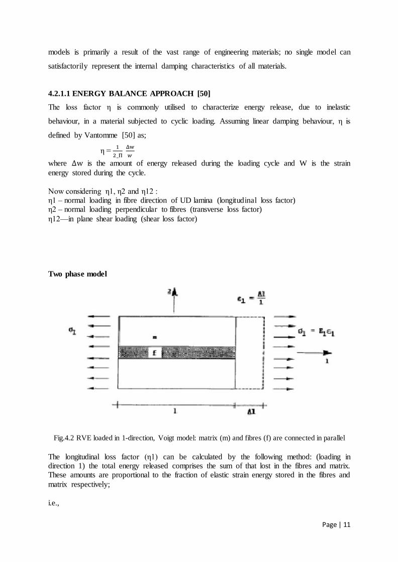
Two phase model
Fig.4.2 RVE loaded in 1-direction, Voigt model: matrix (m) and fibres (f) are connected in parallel
The longitudinal loss factor (ε1) can be calculated by the following method: (loading in direction 1) the total energy released comprises the sum of that lost in the fibres and matrix. These amounts are proportional to the fraction of elastic strain energy stored in the fibres and
matrix respectively;
i.e.,
Page | 12
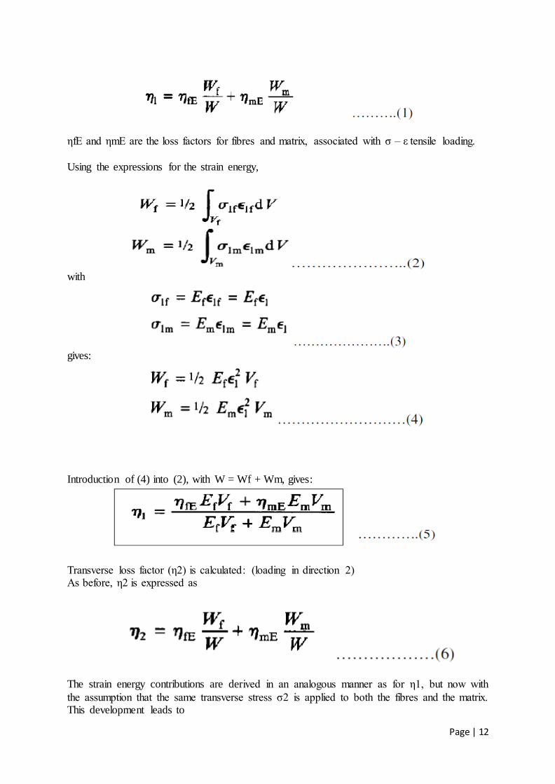
εfE and εmE are the loss factors for fibres and matrix, associated with ζ – ε tensile loading.
Using the expressions for the strain energy,
with
gives:
Introduction of (4) into (2), with W = Wf + Wm, gives:
Transverse loss factor (ε2) is calculated: (loading in direction 2) As before, ε2 is expressed as
The strain energy contributions are derived in an analogous manner as for ε1, but now with
the assumption that the same transverse stress ζ2 is applied to both the fibres and the matrix. This development leads to
Page | 13
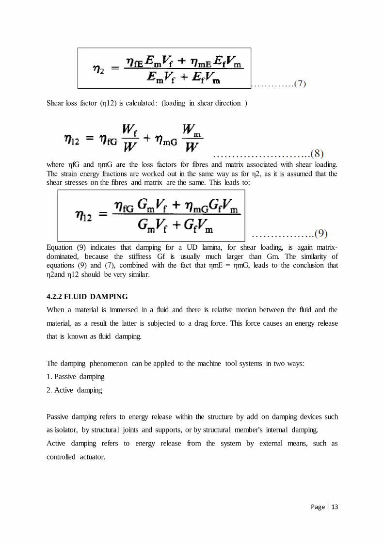
Shear loss factor (ε12) is calculated: (loading in shear direction )
where εfG and εmG are the loss factors for fibres and matrix associated with shear loading.
The strain energy fractions are worked out in the same way as for ε2, as it is assumed that the shear stresses on the fibres and matrix are the same. This leads to:
Equation (9) indicates that damping for a UD lamina, for shear loading, is again matrix-
dominated, because the stiffness Gf is usually much larger than Gm. The similarity of equations (9) and (7), combined with the fact that εmE = εmG, leads to the conclusion that
ε2and ε12 should be very similar.
4.2.2 FLUID DAMPING
When a material is immersed in a fluid and there is relative motion between the fluid and the
material, as a result the latter is subjected to a drag force. This force causes an energy release
that is known as fluid damping.
The damping phenomenon can be applied to the machine tool systems in two ways:
1. Passive damping
2. Active damping
Passive damping refers to energy release within the structure by add on damping devices such
as isolator, by structural joints and supports, or by structural member's internal damping.
Active damping refers to energy release from the system by external means, such as
controlled actuator.

Page | 14
4.2.3 STRUCTURAL DAMPING
Rubbing friction or contact among different elements in a mechanical system causes
structural damping [49]. Since the release of energy depends on the particular characteristics
of the mechanical system, it is very difficult to define a model that represents perfectly
structural damping. Coulomb-friction model is an imperative utilised to describe energy
released due to friction. Regarding structural damping (energy released by contact or impacts
at joints), energy release is determined by means of the coefficient of restitution of the two
components that are in contact. Assuming an ideal Coulomb friction, the damping force at a
join can be expressed through the following expression:
f = c.sgn ( )
where:
f = damping force, = relative displacement at the joint, c= friction parameter
and the signum function is defined by:
sgn (x) = 1 for x ≥ 0
sgn (x) = -1 for x < 0
4.3 DAMPING MECHANISMS IN COMPOSITE MATERIALS
Damping mechanisms in composite materials differ entirely from those in conventional
metals and alloys [23]. The different sources of energy release in fibre-reinforced composites
are:
a) Viscoelastic nature of matrix and/or fibre materials
(b) Damping due to interphase
(c) Damping due to damage which is of two types:
(i) Frictional damping due to slip in the unbound regions between fibre and matrix.
(ii) Damping due to energy release in the areas of matrix cracks and broken fibres etc.
(d) Damping in Viscoelastic materials.
(e) Damping in Thermo elastic materials.

Page | 15
CHAPTER 5
VISCOELASTIC DAMPING
5.1 FACTORS AFFECTING VISCO ELASTIC DAMPING:
Important viscoelastic behaviours that affect in damping are:
Creep under constant stress
Relaxation under constant strain
Hysteresis loop due to cyclical stress
Strain rate dependency on strain rate curve
These behaviours are discussed in the later sections of the chapter. This paper describes the
damping behavior of carbon epoxy composite with riveted joint. The rivets utilised are mode
of structural steel.
5.2 MATERIALS UTILISED
The composite material utilised in the analysis Carbon Fibre Composite Materials, Fibre /
Epoxy resin (120°C Cure).
MECHANICAL PROPERTIES:
Fibres @ 0° (UD), 0/90° (fabric) to loading axis, Dry, Room Temperature, Vf = 60%
(UD), 50% (fabric)
Epoxy resin and Standard CF Fabric

Page | 16
Table 1: Properties of CARBON-FIBRE EPOXY Composite

Page | 17
CHAPTER 6
MATHEMATICAL MODELLING
6.1 STRUCTURAL DAMPING FACTOR (γ):
The viscous damping coefficient c, hysteretic damping coefficient h and the damping ratio δ
are considered to be the 3 important factors in damping of structures. But, there is another
very vital factor, structural damping factor γ, to describe the property of the damping
material.
The forced motion equation of a single spring mass system with a hysteretic damper is
For a harmonic problem, it becomes
For the modal damping, , therefore, we have
where, is known as the structural damping factor or modal damping ratio.
For the viscous damping, similarly, the viscous damping factor is γ=2δ.
6.2 COMPLEX STIFFNESS
The damping of the whole structure can be influenced by the polymer material due to its
material stiffness as well as by its damping. These 2 properties are conveniently quantified by
the complex Young‘s modulus or the complex shear modulus and are usually assumed to
be equal for a given material.
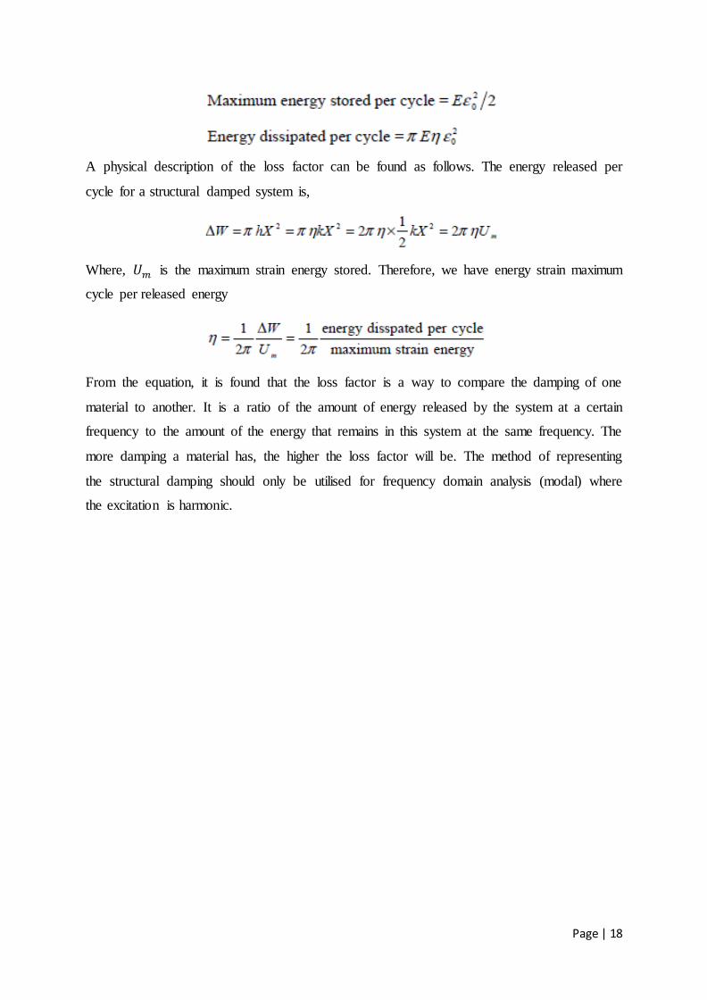
When the material is subjected to cyclic stress and strain with amplitude and , the
maximum energy stored and released per cycle in a unit volume are as
Page | 18
A physical description of the loss factor can be found as follows. The energy released per
cycle for a structural damped system is,
Where, is the maximum strain energy stored. Therefore, we have energy strain maximum
cycle per released energy
From the equation, it is found that the loss factor is a way to compare the damping of one
material to another. It is a ratio of the amount of energy released by the system at a certain
frequency to the amount of the energy that remains in this system at the same frequency. The
more damping a material has, the higher the loss factor will be. The method of representing
the structural damping should only be utilised for frequency domain analysis (modal) where
the excitation is harmonic.
Page | 19
CHAPTER 7
MODELING AND ANALYSIS OF
THE COMPOSITE WITH RIVETS
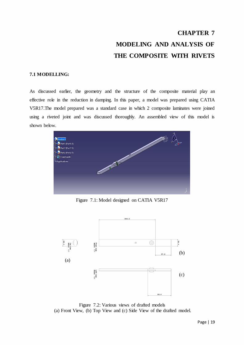
7.1 MODELLING:
As discussed earlier, the geometry and the structure of the composite material play an
effective role in the reduction in damping. In this paper, a model was prepared using CATIA
V5R17.The model prepared was a standard case in which 2 composite laminates were joined
using a riveted joint and was discussed thoroughly. An assembled view of this model is
shown below.
Figure 7.1: Model designed on CATIA V5R17
Figure 7.2: Various views of drafted models (a) Front View, (b) Top View and (c) Side View of the drafted model.
(a)
(b)
(c)

Page | 20
7.2 ANALYSIS OF THE MODEL IN ANSYS
In this paper, using ANSYS software harmonic and modal analysis along with transient
response and dynamic explicit modelling have been done for vibration damping. Several key
points were deduced after the analysis of the model prepared.
7.2.1 GENERAL OVERVIEW OF DAMPING IN ANSYS
The damping matrix C in ANSYS may be utilised in harmonic, damped modal and transient
analysis as well as substructure generation. In its most general form, it is:
Where,
α constant mass matrix multiplier
β constant stiffness matrix multiplier
βj constant stiffness matrix multiplier
βc variable stiffness matrix multiplier
δ constant damping ratio, the damping ratio δ should be 2ε where ε is the loss factor.
f frequency in the range between fb (beginning frequency) and fe (end frequency);
[Cδ] frequency-dependent damping matrix
[Cδ] may be calculated from the stated δr (damping ratio for mode shape r) and is
never clearly computed.
is the rth mode shape
fr frequency associated with mode shape r

Page | 21
δ constant damping ratio
δ mr modal damping ratio for mode shape r
[Ck] element damping matrix
7.2.2 RAYLEIGH DAMPING (α AND β):
The most common form of damping is the Rayleigh type damping.
[C] = α[M] + β[K].
In this representation, the matrix becomes the modal coordinates which is the major
advantage of using this model.
C’ is the diagonal, so for the rth mode, the equation of motion can be uncoupled. Each one is
of the form
Let
The equation reduces to
Where, δmr is the rth
modal damping ratio.
The values of α and β are not known directly, but are calculated from modal damping ratios,
δmr. It is the ratio of actual damping to critical damping for a particular mode of vibration, r.
From the above equation, we have
In many practical structural problems, the mass proportional damping α, represents frictional
damping and may be ignored when (α = 0). In such case, the β damping can be estimated
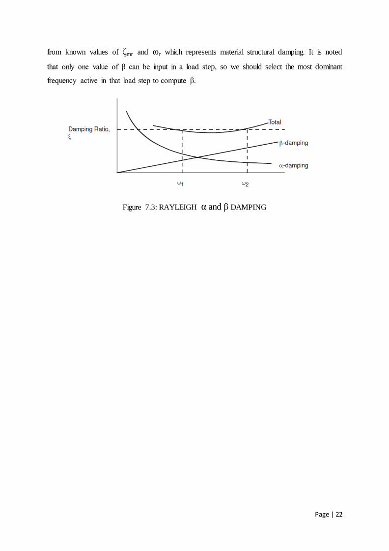
Page | 22
from known values of δmr and ωr which represents material structural damping. It is noted
that only one value of β can be input in a load step, so we should select the most dominant
frequency active in that load step to compute β.
Figure 7.3: RAYLEIGH α and β DAMPING

Page | 23
CHAPTER 8
FINITE ELEMENTAL ANALYSIS OF THE MODEL
In this paper, various structural analyses have been done for the previously prepared model
which was prepared in CATIA and then imported to ANSYS.
8.1 MODAL ANALYSIS
Modal analysis determines the natural frequency and mode shape of a structure. The natural
frequency and mode shape are important parameters in the design of a structure for dynamic
loading conditions and can be utilised in spectrum analysis or a mode superposition harmonic
or transient analysis.
Figure 8.1: ANSYS Modal
Page | 24
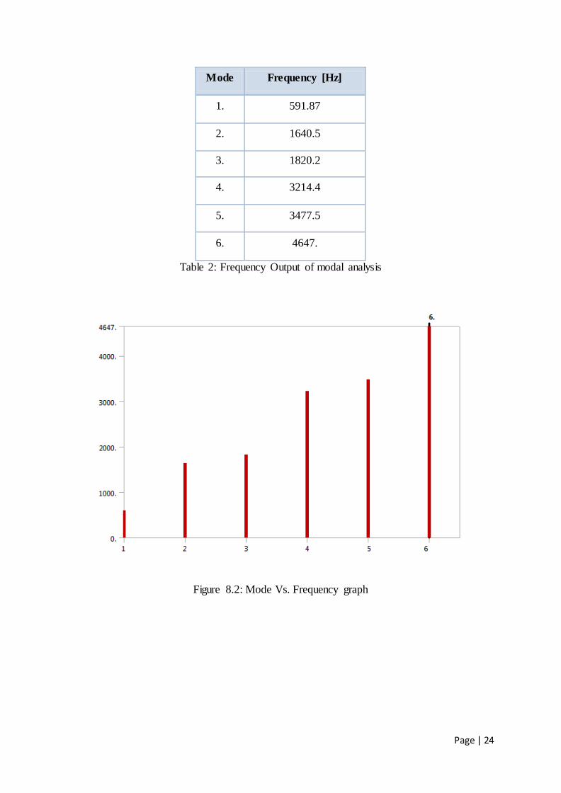
Mode Frequency [Hz]
1. 591.87
2. 1640.5
3. 1820.2
4. 3214.4
5. 3477.5
6. 4647.
Table 2: Frequency Output of modal analysis
Figure 8.2: Mode Vs. Frequency graph
Page | 25
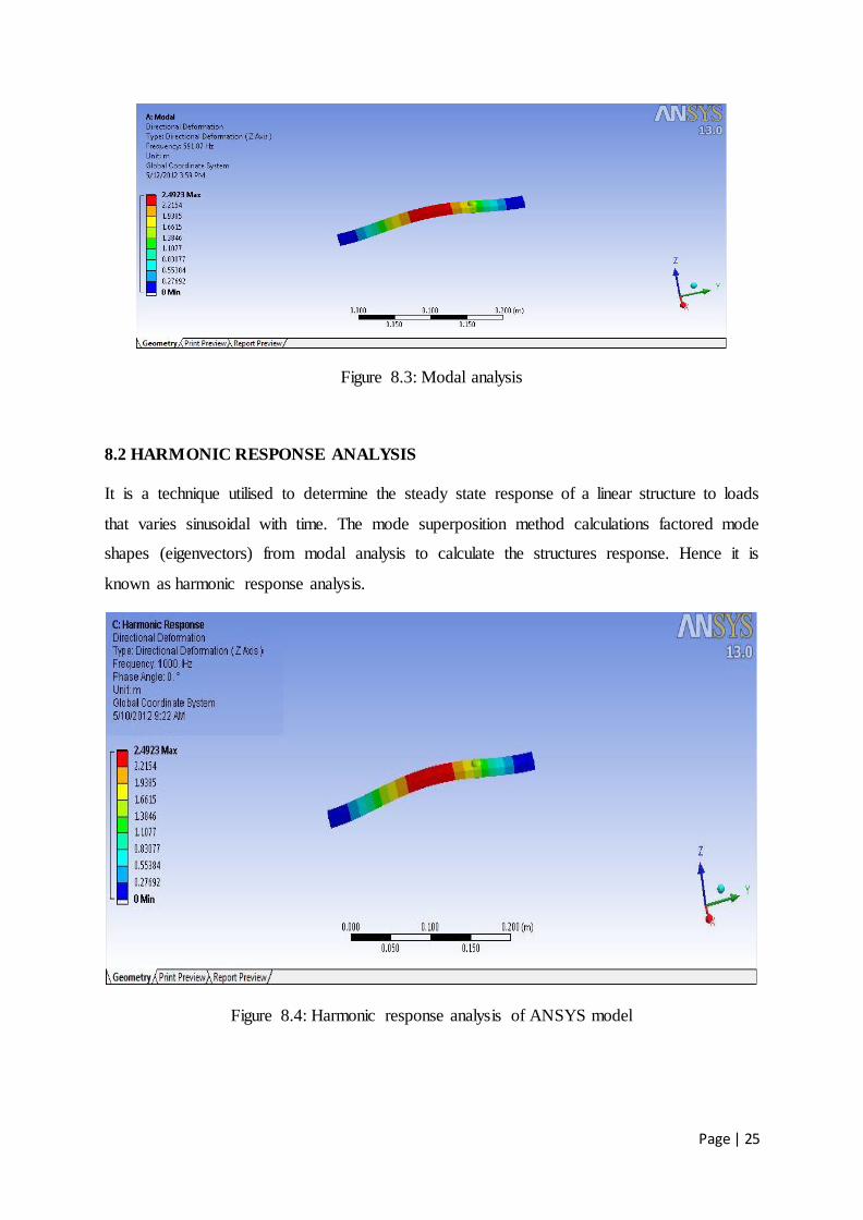
Figure 8.3: Modal analysis
8.2 HARMONIC RESPONSE ANALYSIS
It is a technique utilised to determine the steady state response of a linear structure to loads
that varies sinusoidal with time. The mode superposition method calculations factored mode
shapes (eigenvectors) from modal analysis to calculate the structures response. Hence it is
known as harmonic response analysis.
Figure 8.4: Harmonic response analysis of ANSYS model
Page | 26
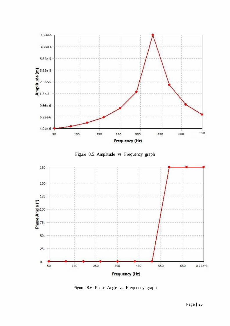
Figure 8.5: Amplitude vs. Frequency graph
Figure 8.6: Phase Angle vs. Frequency graph
Page | 27
8.3 TRANSIENT DYNAMIC ANALYSIS
It is also called time history analysis. It is the technique utilised to determine the dynamic
response of a system under the action of any time dependent load.
The basic equation of motion solved by a transient dynamic analysis is
(M){u‖}+(C){u‘}+(K){u}={f(t)}
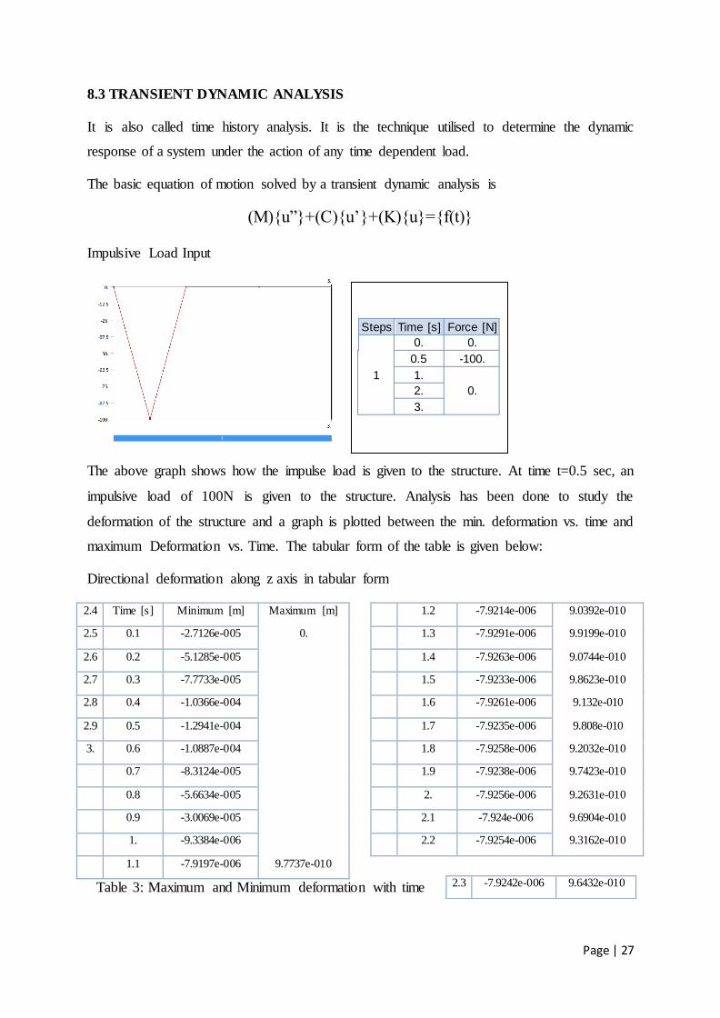
Impulsive Load Input
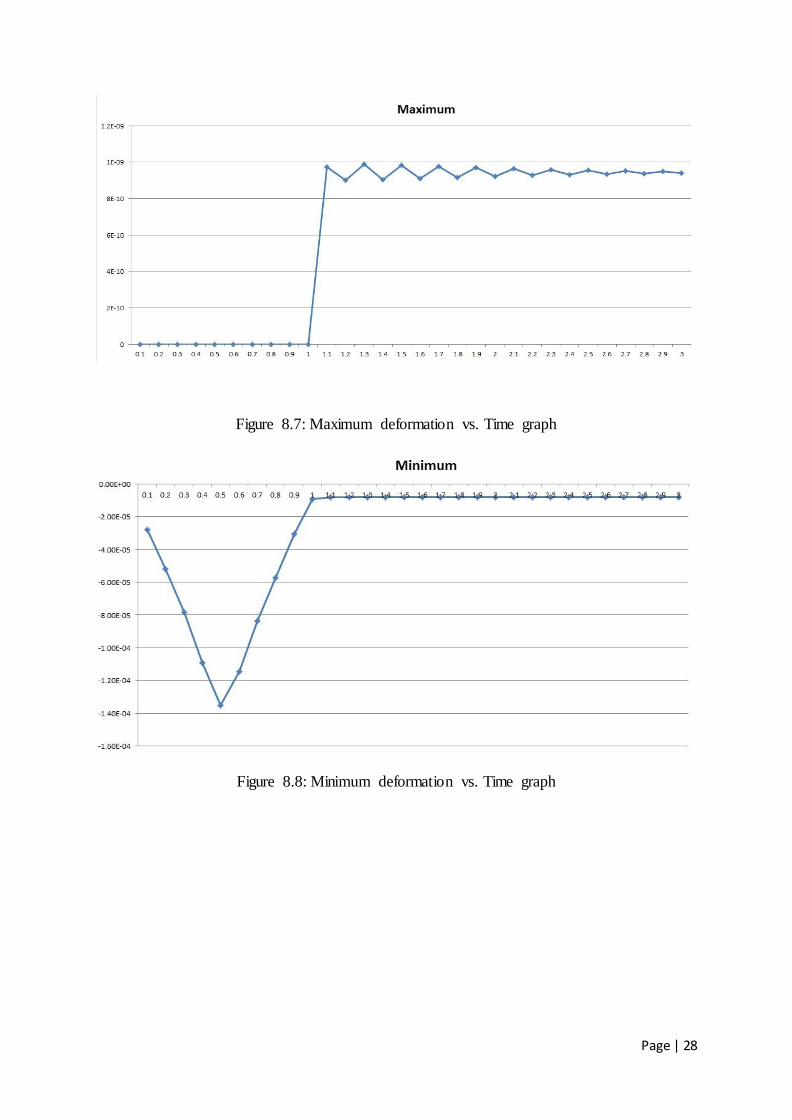
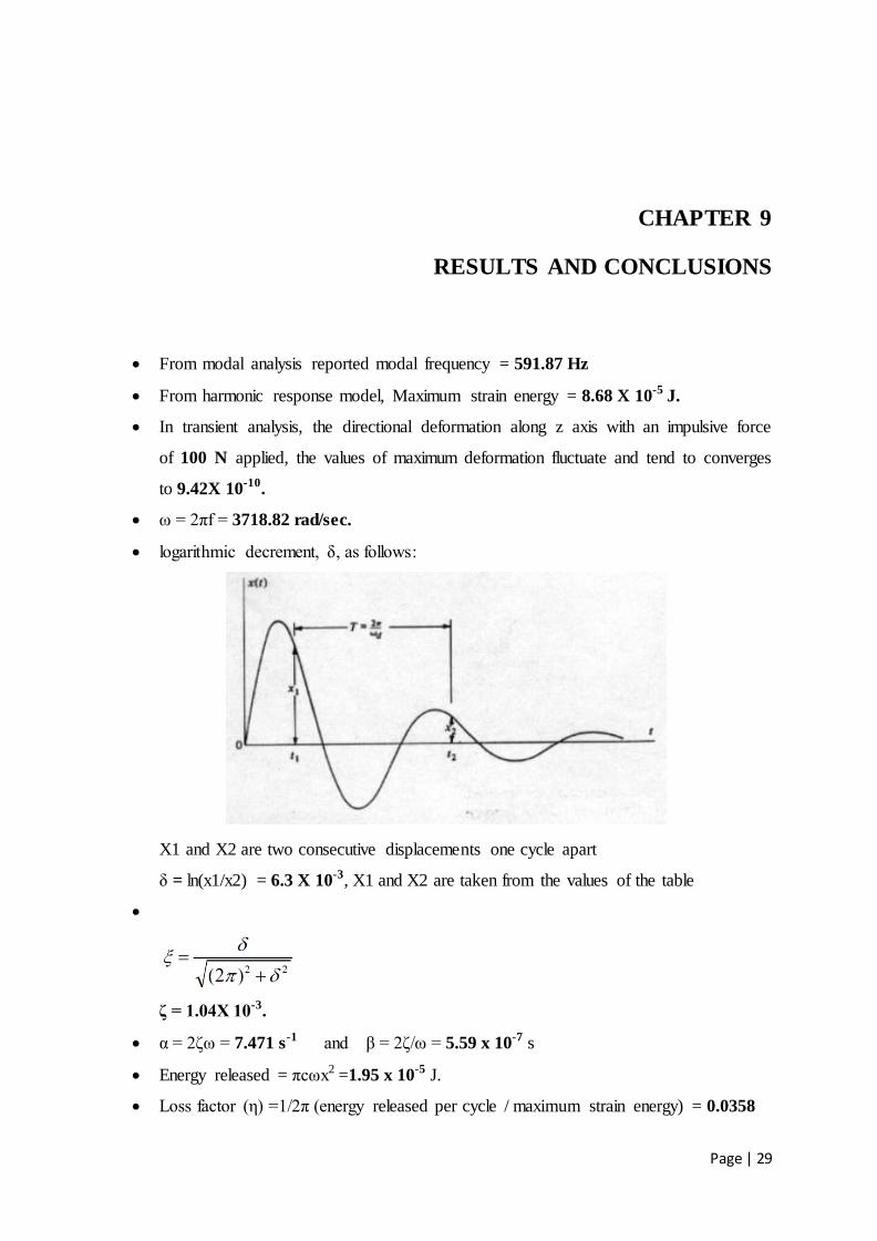
The above graph shows how the impulse load is given to the structure. At time t=0.5 sec, an
impulsive load of 100N is given to the structure. Analysis has been done to study the
deformation of the structure and a graph is plotted between the min. deformation vs. time and
maximum Deformation vs. Time. The tabular form of the table is given below:
Directional deformation along z axis in tabular form
2.4 Time [s] Minimum [m] Maximum [m]
2.5 0.1 -2.7126e-005 0.
2.6 0.2 -5.1285e-005
2.7 0.3 -7.7733e-005
2.8 0.4 -1.0366e-004
2.9 0.5 -1.2941e-004
3. 0.6 -1.0887e-004
0.7 -8.3124e-005
0.8 -5.6634e-005
0.9 -3.0069e-005
1. -9.3384e-006
1.1 -7.9197e-006 9.7737e-010
1.2 -7.9214e-006 9.0392e-010
1.3 -7.9291e-006 9.9199e-010
1.4 -7.9263e-006 9.0744e-010
1.5 -7.9233e-006 9.8623e-010
1.6 -7.9261e-006 9.132e-010
1.7 -7.9235e-006 9.808e-010
1.8 -7.9258e-006 9.2032e-010
1.9 -7.9238e-006 9.7423e-010
2. -7.9256e-006 9.2631e-010
2.1 -7.924e-006 9.6904e-010
2.2 -7.9254e-006 9.3162e-010
Table 3: Maximum and Minimum deformation with time 2.3 -7.9242e-006 9.6432e-010
Steps Time [s] Force [N]
1
0. 0.
0.5 -100.
1.
0. 2.
3.
Page | 28
Figure 8.7: Maximum deformation vs. Time graph
Figure 8.8: Minimum deformation vs. Time graph
Page | 29
CHAPTER 9
RESULTS AND CONCLUSIONS
From modal analysis reported modal frequency = 591.87 Hz
From harmonic response model, Maximum strain energy = 8.68 X 10⁻⁵ J.
In transient analysis, the directional deformation along z axis with an impulsive force
of 100 N applied, the values of maximum deformation fluctuate and tend to converges
to 9.42X 10⁻¹⁰.
ω = 2πf = 3718.82 rad/sec.
logarithmic decrement, δ, as follows:
X1 and X2 are two consecutive displacements one cycle apart
δ = ln(x1/x2) = 6.3 X 10⁻³, X1 and X2 are taken from the values of the table
ζ = 1.04X 10⁻³.
α = 2δω = 7.471 s-1 and β = 2δ/ω = 5.59 x 10⁻⁷ s
Energy released = πcωx2 =1.95 x 10⁻⁵ J.
Loss factor (ε) =1/2π (energy released per cycle / maximum strain energy) = 0.0358
Page | 30
REFERENCES
1. Cochardt, A.W., 1954, A method for determining the internal damping of machine members,
ASME, Journal of Applied Mechanics, Vol. 76, No. 9, pp. 257-262.
2. Goodman, L.E. and Klumpp, J.H., 1956, Analysis of slip damping with reference to turbine-
blade vibration, ASME, Journal of Applied Mechanics, Vol. 23, pp. 421–429.
3. Beards, C.F., 1992, Damping in structural joints, The Shock and Vibration Digest, Vol. 24, No.
7, pp. 3-7.
6. Ruzicka, J. E., ―Structural Damping‖. ASME, New Jersey (1959).
7. Lazan, B. J., ―Damping of Materials and Members in Structural Mechanics‖. Pergamon
Press, London (1968)
8. Nashif, A. D., Jones, D. I. G. and Henderson, J. P., ―Vibration Damping‖. John Wiley &
Sons, Inc., New York (1985).
9. Jones, D. I. G., ―Handbook of Viscoelastic Vibration Damping‖. John Wiley & Sons, Inc.,
New York (2001).
10. Sun, C. T., Lu, Y. P., ―Vibration Damping of Structural Elements‖. Prentice Hall PTR,
Englewood Cliffs, NJ , (1995).
11. Beards, C. F., ―Structural Vibration Analysis: Modeling, Analysis, and Damping of
Vibrating Structures‖. Halsted Press, Chichester (1983).
12. Ungar, E. E., "Structural Damping", Chapter 12 in Noise and Vibration Control
Engineering: Principles and Applications, Leo. L. Beranek (Editor). John Wiley & Sons,
Inc.,(1992).
13. Mead, D. J., ―Passive Vibration Control‖. John Wiley & Sons, New York (1999).
14. Bert, C.W., ―Composite materials: A survey or the damping capacity of fibre reinforced
composites in damping applications for vibration control‖, AMD-Vol. 38. (1980).
15. Nashif, A.D, Jones, D.I.G and Henderson, J.P. Vibration Damping, Wiley, New York,
(1985).
16. Chandra, R., Singh S.P, and Gupta.K Damping studies in fibre-reinforced composites—a
review. Composite Structs, 46(1), 41-51, (1999).
17. Gibson, R.F., Chaturvedi, S.K. and Sun, C.T., ―Complex moduli of aligned discontinuous
Page | 31
fibre-reinforced polymer composites‖, J. Mater Sci., Vol. 17. pp. 3499-3509 (1982).
18. Gibson, R.F., Chaturvedi, S.K. and Sun, C.T., ―Internal damping of short-fibre reinforced
polymer matrix composites‖, Comput. Struct 20, pp. 391—401, (1985).
19. Sun, C.T , Wu, J.K. and Gibson, R.F., ―Prediction of material damping of laminated
polymer matrix composits'‘. J. Mater. Sci. 22, pp. 1006-1012, (1987).
20. Adams, R.D. and Bacon, D.G.C, ―Effect of fibre orientation and laminate geometry on
the dynamic properties of CFRP , J Compos.Mater. 7, pp. 402-428, (1973).
21. Lin D.X, Ni R.G and Adams R.D, ―Prediction and measurement of the vibrational
damping parameters of carbon and glass fibre-reinforced plastics plates‖, J. Composite.
Materials. 18, pp. 132 -152 (1984).
22. Ni R.G and Adams R.D., ―A rational method for obtaining the dynamic mechanical
properties of lamina for predicting the stiffness and damping of laminated plates and beams‖,
Composites 15, pp. 193—199, (1984).
23. Morison W.D, ―The prediction of material damping of laminated composites‖, Can.
Aeronaut. Space J. 28, pp. 372-382, (1982).
24. Kinra, V.K., Wren G.G., Rawal S.P. and Misra. M.S. ―On the influence of ply-angle on
damping and modulus of elasticity of a metal-matrix composite‖, Metall. Trans, 22A. pp.
641- 651. (1991).
25. Ungar, E.E. and Kerwin, J.R., ―Loss factors or viscoelastic systems in terms of energy
concepts,‖ J Acoust. Soc. Am., 34, No. 7, 954.958, (1962).
27. Johnson C. D. and Kienholz D. A., ―Finite element prediction of damping in structures
with constrained Viscoelastic layers,‖ AIAA J., 20, No. 9, 1284-1290,(1982).
28. Gibson, R. F. and Plunkett R. , ―A forced-vibration technique for measurement of material
damping. Experimental Mechanics‖, Volume 17, Number 8 / August, : 297-302, (1977).
29. Suarez, S. A., Gibson, R. F. and Deobold, L. R., ―Random and Impulse Techniques for
Measurements of Damping in Composite Materials,‖ Experimental Techniques, Vol. 8, No.
10, pp. 19–24,(1984).
30. Gibson Ronald, F. ―Modal vibration response measurements for characterization of
composite materials and structures‖. Composites science and technology, American Society
of Mechanical Engineers, Aerospace Division's Symposium (1999) 2000, vol. 60,pp. 2757-
2802 (42 ref.), pp. 2769-2780.
31. Lin D.X, Ni R.G, Adams R.D. ―Prediction and measurement of the vibrational damping
Page | 32
parameters of carbon-glass fibre-reinforced plastic Plates‖. J Comp Mater; 18: 132-52.(1984).
32. Koo K.N, Lee.I. ―Vibration and damping analysis of composite laminates using
deformable finite element‖. AIAA J; 31 (4): 728-35,(1993).
33. Singh S.P., Gupta K., ―Damped free vibrations of layered composite cylindrical shells‖.
J Sound Vib 172 (2) : 191-209 (1994).
34. Myklestad N. O., ―Journal of Applied Mechanics. The concept of complex damping‖. 19,
284-286,(1952).
35. Corsarov R.D., Sperling L.H., ―Sound and Vibration Damping with Polymers‖, ACS
Symposium Series, Vol. 424, American Chemical Society, Washington, DC, (1990).
36. Madigosky, W.M., Lee G.F., ―Improved resonance technique for materials
characterization‖, Journal of the Acoustical Society of America, 73, 1374–1377, (1983).
37. Rahman, M., Mansur, A. and Karim, B. ―Non-conventional material for machine tool
structures‖[J]. JISM International Journal, Series C, 44(1), 1–11, (2001).
38. Lee, D.G., Chang, S.H. and Kim, H.S. ―Damping improvement of machine tool columns
with polymer matrix fibre composite materials‖. Compos. Struct., 43,155–163, (1998).