Embed Size (px)
Citation preview

Damage Assessment of a Wellhead Using Geometric Analysis
3D Modelling Case Study
www.welaptega.com

Wellhead Repair 3D Modelling Case Study
2 | P a g e
Case Study: Damage Assessment of a Wellhead using 3D Computer-based
Photogrammetry as a Geometric Analysis Tool
Location: UK Oil and Gas Sector
The Project:
During installation, a wellhead was impacted by a Blow-out Preventer (BOP), resulting in inward bending
of the inner tree hub, deformation and smearing of material at the top and outer BOP mating surfaces of
the outer hub, and wedging of the gasket between the inner and outer hubs. The client required the
geometry of the wellhead to facilitate removal and replacement of the damaged gasket.
Figure 1: Wellhead and Tree Cap Prior to Gasket Removal
The Solution:
Welaptega constructed two 3D models to provide the geometry of the wellhead prior to, and following
the removal of the gasket. A marker and two magnets were placed on the wellhead during photography
to provide scaling references.

Wellhead Repair 3D Modelling Case Study
3 | P a g e
Data Collection:
The 3D modeling system was deployed to a depth of approximately 140m to capture images of the
wellhead from the camera stations shown in the following figure. Camera stations are represented in
purple, and the model point cloud is shown in yellow.
Figure 2: Camera Stations Used for Image Capture
A total of 164 images were processed to generate the model shown in the following figures.
Figure 3: Wellhead 3D Model I (2D)
Figure 4: Wellhead 3D Model I (2D with photo-overlay)

Wellhead Repair 3D Modelling Case Study
4 | P a g e
The same model is provided below in 3D. Rotate by clicking the model to activate, then clicking and
dragging the mouse cursor. The model surface can be viewed in using different surfaces by changing the
“Model Render Mode” setting.
*Click model to activate.
Figure 5: Wellhead 3D Model I (3D)
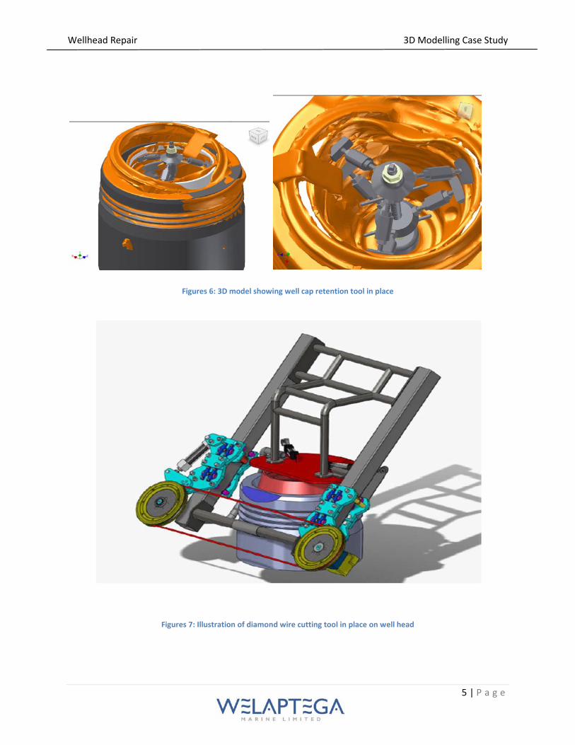
The wellhead I model was exported as a *.stp file and provided to the client to facilitate the design of
several remote and diver-operated tool systems, including a tool to hold the well cap in place (Figure 6)
a diamond wire cutting tool to remove smeared material and dress sealing faces (Figure 7), and a tool to
assist with the removal of the damaged gasket.
Divers were then deployed to remove the damaged gasket, grind the outer hub surface to be flush with
the rest of the wellhead, and cut or bend the internal tree cap to prevent obstruction of tooling to be
deployed at a later date.
Wellhead Repair 3D Modelling Case Study
5 | P a g e
Figures 6: 3D model showing well cap retention tool in place
Figures 7: Illustration of diamond wire cutting tool in place on well head

Wellhead Repair 3D Modelling Case Study
6 | P a g e
Following the removal of the gasket and excess material the entire wellhead was surveyed (Figure 8) and
a second 3D model of the wellhead was created (Figure 9 and 10).
Figures 8: Survey photographs of the wellhead following removal of the gasket
Figure 9: Wellhead II 3D Model
Figure 10: Wellhead II 3D Model (with Photo-overlay)

Wellhead Repair 3D Modelling Case Study
7 | P a g e
The model that is illustrated in Figure 9 is provided below in 3D (Figure 11). The model can be rotated
by ‘left’ clicking the model to activate the 3D mode, and then clicking and dragging the mouse cursor.
The model surface can be viewed in using different surfaces by changing the “Model Render Mode”
setting (right click).
*Click model to activate.
Figure 11: Wellhead II 3D Model (3D)
Results:
Both 3D models were provided to the client as *.stp files, which allowed them to be imported into of
the standard 3D CAD/CAM software packages.
The first 3D model (wellhead I ) was used to design as ‘the plug’ to design the well cap retention tool,
the gasket pulling tool, and the diamond wire cutting tool that was used to remove excess material.
The second model (wellhead II) was used to assess the condition of the sealing surface for the
replacement gasket, and then was used by the valve assembly manufacturer to design the new interface.