Embed Size (px)
Citation preview

-i-
DAM SAFETY PROJECT REVIEW GUIDE
[WEB PAGE VERSION]
September 23, 1994(Third Revision June/1/2000)
(SUPERSEDES "Project Review Guide," Revised May 16, 1996)
This Guide is Subject to Change. Prior to beginning a new project, call the office of the State
Engineer for status of updates.
303-866-3581
Dam Safety BranchDivision of Water ResourcesOffice of the State Engineer
Department of Natural ResourcesDenver, Colorado

-ii-
PURPOSE OF THE DAM SAFETY PROJECT REVIEW GUIDE
This document has been created to provide a technical guidefor the engineering community involved with the design of damsunder the Colorado Statutes and the "Rules and Regulations for DamSafety and Dam Construction." In addition, this guide has beenwritten to help the engineer follow the rules for a specificproject. The guide is divided into three parts plus references.
Part I - ADMINISTRATIVE REQUIREMENTS: Lists the requireddocuments, description of the documents, and fees associatedwith filing an application to build, repair or to modify ajurisdictional dam in Colorado.
Part II - DESIGN AND TECHNICAL CRITERIA: Outlines, clarifies,and supplements the technical requirements of the Rules andRegulations.
Part III - CONSTRUCTION: Provides information concerningexpectations for monitoring, recording and documenting theconstruction of any work on a dam.
No document can be inclusive of all design problems confrontedby an engineer, nor can it be expected to foresee future changes tolaw and rules. In addition, no guide can be a substitute for soundengineering judgment or experience. Therefore, this guide issubject to change as improved techniques and policies become known.
Because this a guide for the engineering community,suggestions and comments for additions and changes are welcome atany time. Please write or call the following:
Colorado Division of Water ResourcesDam Safety Branch1313 Sherman Street Rm 818Denver, Colorado 80203303-866-3581

-iii-
CONTENTS
LIST OF FIGURES -v-
PART I. ADMINISTRATIVE REQUIREMENTS
A. Filing an Application I-1 1. Preliminary Filing2. Supplemental Filing3. Final Filing
B. Document Descriptions I-2 1. Application Forms2. Construction Plans (Drawing Standards)3. Construction Specifications Standards4. Hazard Classification Report5. Hydrology Report6. Geotechnical and Structural Analysis Report7. Design Report8. Instrumentation Plan9. Cost Estimate
10. Filing Fee
PART II. DESIGN AND TECHNICAL CRITERIA
A. Hazard Classification II-11. Purpose2. Criteria for Hazard Classification3. Criteria for Size of Dam4. Hazard Classification Report
B. Hydrologic Design II-51. Design Rainfall2. Inflow Design Flood Parameters3. Incremental Damage Analysis4. Hydrology Report
C. Geotechnical Criteria for Investigation and Design II-141. Geotechnical/Geological Reports2. Static Stability3. Seismic Stability4. Design Criteria5. Concrete Dams
D. Spillway Design Considerations II-261. General Polices2. Design Considerations3. Terminal Structures4. Fuse Plugs & "Hydroplus" system gates (tm)

-iv-
E. Outlet Design Considerations II-281. Outlet Capacity Requirements2. Outlet Design Considerations
F. Reservoir & Area II-301. Seepage2. Reservoir Slides3. Reservoir Site Cleaning4. Reservoir Rights of Way5. Accessibility to Dam
G. Water Diversion Control Plans II-311. Diversion Control2. Design Considerations3. Approval of Plan
H. Instrumentation Plan II-321. Purpose2. Required Instrumentation3. Design Criteria
I. Monitoring Plan II-351. Purpose2. Frequency of Measurement3. Recording and Reporting Instrument Readings4. Analysis of Data
J. Emergency Preparedness Plan II-40
PART III. CONSTRUCTION
A. Construction Quality control III-11. Purpose2. Construction Schedule3. Preconstruction Meeting for Class I Dams4. Class II and Class III Dams
B. Role of Engineers During Construction III-51. State Engineer2. Project Engineer
C. End of Construction Documentation III-71. Final Inspection Schedule2. Project Close and Documentation
REFERENCES III-8

-v-
LIST OF FIGURES
Figure PageII-1 Design Rainfall for New or Enlarged Dams II-5II-2 Design Rainfall for Evaluation of Spillway
Enlargement on Existing Dams II-5II-3 Precipitation Depth-Duration Values for HEC-1
"PH" Card II-7II-4 Arkansas River LAG Coefficients (USBR) II-10II-5 Seismic Stability Analysis Decision Flow Chart DeletedII-6 Instrumentation Requirements for New or
Enlarged Dams II-32II-7 Instrumentation Requirements for Existing Dams II-32II-8 Field Seepage Data Record II-37II-9 Field Piezometer Data Record II-38II-10 Field Movement Monument Survey Data Record II-39III-1 Construction Control & Reporting Requirements III-4

I-1
PART I
ADMINISTRATIVE REQUIREMENTS
A. FILING AN APPLICATION:
1. Preliminary Filing: The documents listed below must besubmitted as an application for approval to construct a newjurisdictional dam or enlargement in Colorado (only applicabledocuments are required for repairs or modifications to existingdams See Rule 6.A.). The various reports may be submitted in asingle bound document.
a. Application Form 1 eachb. Construction Plans (24x36 prints) 1 eachc. Construction Specifications 1 eachd. Classification Report 2 eache. Hydrology Report 2 eachf. Geotechnical and Structural
Analysis Report 2 eachg. Design Report 2 eachh. Instrumentation and Monitoring Plan 2 eachi. Detailed Cost Estimate
(include in design report)j. Filing Fee 1 check
(NOTE: Additional copies of reports, drawings andspecifications may be requested by the StateEngineer as required.)
2. Supplemental Filing: If any minor corrections arerequired to the application, the engineer should submit thefollowing items:
a. Corrected documents as per review memo .b. Revised cost estimate, if change occurs.
3. Final Filing: Once a design is considered acceptable forconstruction, the design engineer will be notified to submit thefinal documents consisting of the items listed below. Approvalwill occur as quickly as possible after the final documents havebeen received.
a. Two copies of any corrected report documents.b. Only the final mylar cover sheet drawing (24x36).c. Four complete sets of blue/black prints (24x36).d. A minimum of five sets of specifications.

I-2
B. DOCUMENT DESCRIPTIONS
1. Application Forms: Application forms are available at nocost from the State Engineer. There are three different forms. Onefor each type of work an owner may expect to perform on ajurisdictional dam. (Copies are found under forms) They are:
a. Application for the review of plans andspecifications for the construction or enlargement of areservoir dam.
b. Application for the review of plans andspecifications for the alteration, modification, orrepair of a reservoir dam.
c. Application for removal or breach of a reservoirdam.
2. Construction Plans (Drawing Standards): (See Rule5.A.(2))
a. The plans shall show the design of the dam andeach appurtenant structure in sufficient detail so thatthe contractor or builder is able to construct thestructure from the plans and specifications. Recorddrawings filed with the State Engineer shall beoriginals, or a high quality reproducible archival copyof the original, and shall be prepared in an appropriatescale so details are legible, drawn with permanent inkon high quality Mylar or equivalent, submitted in anoverall size of 24 inches high and 36 inches wide. Sizelimits are required due to the book and cabinet filingsystem used.
b. Drawings shall have a minimum margin of two (2)inches for binding on the left side (24-inch edge) anda 1/2 inch margin on the right, top and bottom edges.
c. MINIMUM size letters shall be 1/8 inch, or Leroy100 template or equivalent. This permits readablereduced drawings made from microfilm documents.
d. All drawing sheets shall have bar scales in orderto allow scaling of reduced drawings.
e. Each sheet shall have in the lower right-handcorner a 1/2 inch by 3 inch space for the StateEngineer's file number.

I-3
f. Use of the Professional Engineer Seal onreproducible drawings is in a state of administrativeflux. Until final rules by the Board of ProfessionalEngineers are promulgated, the acceptable alternative isdescribed below in I.B.2.h.(7).
g. Each sheet shall be numbered sequentially with thefirst or cover sheet being sheet number one inconjunction with the total number of sheets in the planset; e.g., "Sheet 1 of 6".
h. The front cover sheet, Sheet 1, shall show as aminimum, the following information:
(1) Title or name of the dam (use the officialrecord name).
(2) The name of the owner.
(3) Drawing index including drawing title anddrawing number as described in B.2.g. above.
(4) Water Division , Water District
(5) County where dam is located.
(6) Vicinity map showing location of dam.
(7) Responsible design engineer's printed name, PEnumber, and signature shown in lower right 1/4of drawing. Format as follows:
(signature) Colo. PE No______ (printed name of engineer)
(8) State Engineer's approval statement:
Approved on the ______day of __________,20__.
________________________ State Engineer
By: ________________________ Assistant State Engineer

I-4
(9) Provide space near lower right-hand corner foradding "AS-CONSTRUCTED" statement as follows:
"These plans represent the AS-CONSTRUCTEDconditions of ________dam to the best of ourknowledge and judgement, based in part oninformation furnished by others as of the ___day of__________, 20__
(signature) Colo PE No______ (printed name of engineer)
3. Construction Specifications Standards (See Rule 5.A.(3))
a. Cover sheet shall show at least the following:
(1) Title or name of dam (identical to plans).
(2) Water Division , Water District
(3) County.
(4) Design engineer's seal and signature (as required by CRS 12-25-117)
b. The title page or first sheet behind the covershall show as minimum the following:
(1) Title or name of dam (identical to plans).
(2) Water Division , Water District
(3) County.
(4) Design engineer's seal and signature (as required by CRS 12-25-117)
(5) State Engineer approval
Approved on the day of , 20
State Engineer
By: Assistant State Engineer
c. The specifications shall be indexed.

I-5
d. Final specifications shall be submitted on a goodgrade of white 8-1/2" X 11" paper.
e. Each set of specifications filed shall be bound,and shall include ONLY the technical specifications andother information required herein. PLEASE DO NOTinclude contract administration documents such as noticeto bidders, bid bond, equal opportunity, etc.
f. The General Conditions section of thespecifications shall include the following statementthat:
"Approved plans and specifications shall not bematerially changed without the prior writtenapproval of the State Engineer," AND
"The State Engineer has the authority to requirethe material used and the work of construction tobe accomplished according to rules and regulationsand that construction shall not be consideredcomplete until the State Engineer has accepted thesame in writing." AND
"The owner's engineer will monitor the quality ofconstruction as specified in Rule 9 of the Rulesand Regulations for Dam Safety and DamConstruction, September 30, 1988."
4. Hazard Classification Report: The classification reportis generally the first document prepared since the design standardsare driven by the consequences of a dam failure. This report may besubmitted to the State Engineer for an opinion prior to beginningthe design phase. The report shall be indexed and bound. A filingfee is not required. The standards and criteria for the analysisare found in this guide in PART II.A. Hazard Classification. SeeRules and Regulations, Rule 5.A.(4).
5. Hydrology Report: The hydrology report provides thebasis for approving the size of a reservoir dam spillway. Standards and criteria used by this office for review and analysisare found in PART II.B - Hydrologic Design. The report shall beindexed and bound. This report may be submitted for an opinion ofthe State Engineer before filing an application for approval. Afiling fee is not required. See Rules and Regulations, Rule5.A.(5).
6. Geotechnical and Structural Analysis Report: This reportcontains the information concerning the geology, seismicity, and

I-6
investigation of the soil strength properties from field andlaboratory tests and the availability of materials to assure thedam can be constructed as designed and approved. It also includesa definitive analysis of the stability of the dam during thedifferent loading conditions which the dam may be subjected to. The standards and criteria are found in PART II.C - GeotechnicalInvestigation and Design. The report shall be indexed and bound.See Rules and Regulations, Rule 5.A.(6).
7. Design Report: The intent of the Design Report is toprovide a narrative of the engineer's design philosophy and themethods used to design the various components of the dam notdiscussed in other reports. When copies of the calculations,assumptions, and applicable references are included, a record ofdesign is established and the review process is made easier. Thereport shall be indexed, legible, and clearly documented.Controversial designs and new concepts should be documented andaccompanied with a the calculations and a copy of the pertinentparts of the references which support the design. No furtherdiscussion within this guide is provided for this report. SeeRules and Regulations, Rule 5.A.(7).
8. Instrumentation and Monitoring Plan: The minimumrequirements are found in the Rules and Regulations for Dam Safetyand Dam Construction, however, "PART II.H - Instrumentation Plan"and "PART II.I - Monitoring Plan" provide more definitiverecommendations and reporting format. See Rules and Regulations,Rule 5.A.(8).
9. Cost Estimate: A detailed estimate of cost of theconstruction including engineering fees shall be provided. This isnormally incorporated in the Design Report. The State Engineerrecognizes the sensitivity of this information until theconstruction bid date has closed. For record purposes the filesare not considered public until after a construction contract hasbeen awarded or after the expiration of the plans andspecifications in five years. See Rules and Regulations, Rule5.A.(9).
10. Filing Fee: Effective 1 July 1990, CRS 37-80-110requires a fee of $3.00 per $1000.00 of construction costsincluding the engineering fees. The minimum fee is $100.00 and themaximum fee is $3000.00. The check should be made payable to theSTATE ENGINEER. See Rules and Regulations "Supplement, Paragraph 3.FEES FOR RESERVOIR DAMS."

1
II-1
PART II
DESIGN AND TECHNICAL CRITERIA
A. HAZARD CLASSIFICATION AND SIZE OF DAM:
1. Purpose: The purpose of the Hazard ClassificationStudy is to evaluate the potential consequences of the subject damfailure on residents and property below the dam and to identify thestandards for the investigation, design, and construction whichapply to the proposed project. The purpose of the sizedetermination is to apply the appropriate design standards to theproject.
2. Criteria for Hazard Classification
a. The hazard class is based upon followingassumptions:
(1) The dam fails by erosion of embankmentmaterials initiated by piping, embankment slides ordeterioration of the outlet works.
(2) At the time of failure, reservoir waters arestored to the crest of the emergency spillway.
(3) The dam fails at the maximum section. Areservoir with multiple dams must be analyzed asseparate structures. Design standards of themaximum hazard class applies to all embankments.
b. Because of the sensitivity of the time for a dam tocompletely fail, several reasonable failure rates shouldbe considered. This is especially important if there isa range of reasonable failure rates which would cause adam to be considered for either of two hazardclassifications depending upon the selected failurerate.
c. If the analysis shows loss of life is expected, thedam is classified as Class I. Use of the flood plain byoccasional campers and fishermen is not controlling forthese analyses, since these individuals are expected tobe warned by rising waters and to flee for their lives.

2
II-2
However, the existence of a large establishedcampground adjacent to the stream should be consideredfor Class I. No loss of life is expected to occur if theincreased depth of flow is two feet or less and theproduct of the average flood plain flow velocity and thedepth of flow at a critical area is less than seven. Ifthe failure of the subject dam can cause the failure ofanother Class I dam located downstream, the dam isautomatically considered Class I. Should no loss oflife be expected, the next question of concern isproperty damage.
d. A Class II dam is a dam for which significant damage is expected to occur, but no loss of human lifeis expected in the event of failure of the dam. Significant damage is defined as damage to structureswhere people generally live, work or recreate, or damageto public or private facilities exclusive of unpavedroads and picnic areas. Damage means rendering thestructure uninhabitable or inoperable. It is presumedthat damage is expected to occur when a structure is inmore than two feet of water, or the product of the waterdepth and the average flood plain flow velocity isgreater than seven. A detailed analysis of damage toeach structure may be made as an alternative to theabove presumptions.
e. A Class III dam is one for which no loss of humanlife is expected, and damage to structures and publicfacilities as defined for a Class II dam is not expectedin the event of a failure of the dam.
f. A Class IV dam is a dam for which no loss of humanlife is expected, and which damage will occur only tothe dam owner's property in the event of failure of thedam.
g. In some cases, a classification study may requirean analysis of floods across the state line.
3. Criteria for Size of Dam
a. A "Minor Dam" does not exceed 20 feet in verticalheight and 100 acre-feet in capacity.
b. A "Small Dam" is greater than 20 feet in verticalheight but equal to or less than both 40 feet and 1,000acre-feet in capacity, or is greater than 100 acre-feetbut equal to or less than both 1,000 acre-feet incapacity and 40 feet in vertical height.

3
II-3
c. An "Intermediate Dam" is greater than 20 feet invertical height but equal to or less than both 100 feet and 50,000 acre-feet in capacity, or is greater than1,000 acre-feet in capacity but equal to or less thanboth 50,0000 acre-feet in capacity and 100 feet invertical height.
d. A "Large Dam" is greater than 100 feet in verticalheight, or greater than 50,000 acre-feet in capacity.
4. Hazard Classification Report
a. The report shall include floodplain maps showingthe inundated areas. In the case of a single reservoirwith multiple dams, an analysis of each dam and itsdownstream channel is required.
b. Include cross-sections showing elevations, locationof structures, and channel width at critical sectionswhere development or structures exist. The sectionsshall show the dam break total discharge, averagevelocity and the flood stage elevation.
c. Provide a tabulation of the dam break and channeldischarge parameters and values used for the finalestimated dam break study.
d. The sensitivity study should be summarized intabular form showing the parameters and the results foreach cross-section, and also should show the final studyparameters for comparison purposes.
e. The conclusion shall include the recommended hazardclassification using the criteria as shown above.
f. Append the final computer output to the report in 8-1/2" x 11" paper format.
g. Provide an appendix listing all computer programsand references used for the study.
h. The computer programs that are used by this officeare:
(1) U.S. Army Corps of Engineers "HEC-1 FloodHydrograph Package" (September 1981, or latestversion.) (Requires assuming the dam is overtoppingat the spillway elevation with a small base flowcausing the failure at the maximum section)
(2) National Weather Service "BREACH - An Erosion

4
II-4
Model for Earthen Dam Failures" program by Dr. D.L. Fread,(January 1985) can be used to evaluate thebreach parameters used in the HEC-1 FloodHydrograph Package.
(3) National Weather Service DAMBRK program by Dr.D. L. Fread provides a dynamic analysis of theflood routing downstream of the dam.
5
II-5
B. HYDROLOGIC DESIGN
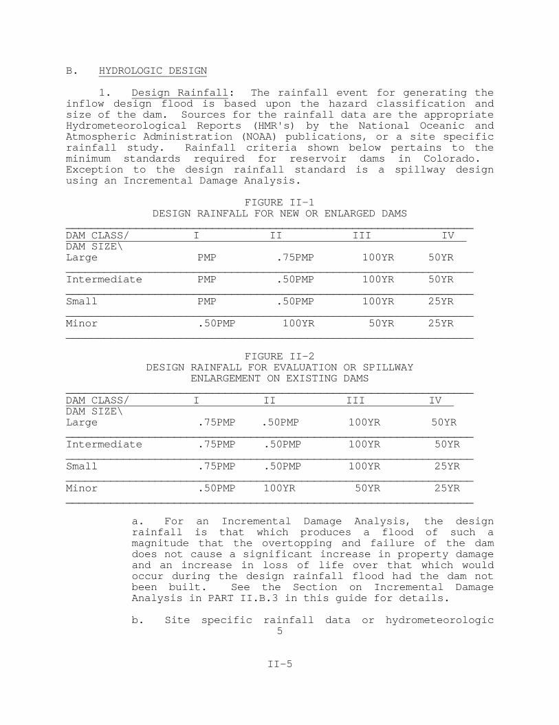
1. Design Rainfall: The rainfall event for generating theinflow design flood is based upon the hazard classification andsize of the dam. Sources for the rainfall data are the appropriateHydrometeorological Reports (HMR's) by the National Oceanic andAtmospheric Administration (NOAA) publications, or a site specificrainfall study. Rainfall criteria shown below pertains to theminimum standards required for reservoir dams in Colorado. Exception to the design rainfall standard is a spillway designusing an Incremental Damage Analysis.
FIGURE II-1DESIGN RAINFALL FOR NEW OR ENLARGED DAMS
________________________________________________________________DAM CLASS/ I II III IV DAM SIZE\Large PMP .75PMP 100YR 50YR________________________________________________________________Intermediate PMP .50PMP 100YR 50YR________________________________________________________________Small PMP .50PMP 100YR 25YR________________________________________________________________Minor .50PMP 100YR 50YR 25YR________________________________________________________________
FIGURE II-2DESIGN RAINFALL FOR EVALUATION OR SPILLWAY
ENLARGEMENT ON EXISTING DAMS________________________________________________________________DAM CLASS/ I II III IV DAM SIZE\Large .75PMP .50PMP 100YR 50YR________________________________________________________________Intermediate .75PMP .50PMP 100YR 50YR________________________________________________________________Small .75PMP .50PMP 100YR 25YR________________________________________________________________Minor .50PMP 100YR 50YR 25YR________________________________________________________________
a. For an Incremental Damage Analysis, the designrainfall is that which produces a flood of such amagnitude that the overtopping and failure of the damdoes not cause a significant increase in property damageand an increase in loss of life over that which wouldoccur during the design rainfall flood had the dam notbeen built. See the Section on Incremental DamageAnalysis in PART II.B.3 in this guide for details.
b. Site specific rainfall data or hydrometeorologic

6
II-6
analysis is determined by following the procedures usedby the National Weather Service or as outlined in theUnited States Bureau of Reclamation (USBR) FloodHydrology Manual (1989), Chapter 3.
c. When using stream gaging stations and rainfall gagedata for determining base data for inflow design floodshaving a frequency equivalent to or more frequent thanthe 100 year event, the analysis procedure will besubject to the State Engineer's approval, or thecalculation shall be based on procedures outlined in thepublication:
"United States Water Resources Council, Guidelinesfor Determining Flood Flow Frequencies, Bulletin #17B of the Hydrology Subcommittee, Revised Edition,Interagency Advisory Committee on Water Data, U.S.Department of the Interior, Geological Survey,Office of Water Data Coordination, Reston,Virginia, 22092, March, 1982"
d. Design Rainfall or Precipitation values are foundin the United States Department of Commerce, NationalOceanic and Atmospheric Administration (NOAA)- NationalWeather Service publications.
(1) Probable Maximum Precipitation (PMP) valuesfor Colorado may be determined from the followingsources:
(a) Hydrometeorological Report No. 51 -"Probable Maximum Precipitation Estimates,United States East of the 105th Meridian."(HMR-51) and Hydrometeorological Report No. 52 - "Application of Probable MaximumPrecipitation Estimates- United State East ofthe 105th Meridian" (HMR-52)
(b) Hydrometeorological Report No. 49 -"Probable Maximum Precipitation, Colorado andGreat Drainages." (HMR-49) This area is westof the Continental Divide.
(c) Hydrometeorological Report No. 55A -"Probable Maximum Precipitation Estimates,United States Between the Continental Divideand the 103rd Meridian." (HMR-55A)
(2) For 100, 50, or 25 year design storms the NOAA
7
II-7
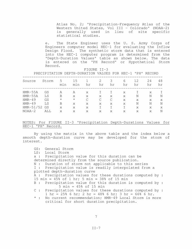
Atlas No. 2; "Precipitation-Frequency Atlas of theWestern United States, Vol III - Colorado" (NOAA-2)is generally used in lieu of site specificstatistical studies.
e. The State Engineer uses the U. S. Army Corps ofEngineers computer model HEC-1 for evaluating the InflowDesign Flood. The synthetic storm data that is enteredinto the HEC-1 computer program is determined from the"Depth-Duration Values" table as shown below. The datais entered on the "PH Record" or Hypothetical StormRecord.
FIGURE II-3PRECIPITATION DEPTH-DURATION VALUES FOR HEC-1 "PH" RECORD
----------------------------------------------------------------Source Storm 5 15 1 2 3 6 12 24 48 min min hr hr hr hr hr hr hr----------------------------------------------------------------HMR-55A GS A A x I I x I x IHMR-55A LS B x x x x x N N NHMR-49 GS * * C C C x x x xHMR-49 LS B x x x x x N N NHMR-51/52 GS x x x I I I x x xNOAA-2 ALL x x x x x x x x N
NOTES: For FIGURE II-3 "Precipitation Depth-Durations Values forHEC-1 "PH" Record.
By using the matrix in the above table and the index below asmooth depth-duration curve may be developed for the storm ofinterest.
GS: General StormLS: Local Stormx : Precipitation value for this duration can be determined directly from the source publication.N : Duration of storm not applicable to this seriesI : Precipitation value is readily interpolated from a plotted depth-duration curveA : Precipitation values for these durations computed by :
15 min = 45% of 1 hr; 5 min = 38% of 15 minB : Precipitation value for this duration is computed by :
5 min = 45% of 15 minC : Precipitation values for these durations computed by :
1 hr = 25% 6 hr; 2 hr = 48% 6 hr; 3 hr = 66% 6 hr.* : No current recommendation; HMR-49 Local Storm is more
critical for short duration precipitation.

8
II-8
2. Inflow Design Flood Parameters: The inflow design floodis based upon the probable future flow of water and is based onreasonable hydrologic and geologic factors. For the purpose of theState Engineer's review, the dimensionless unit hydrographtechnique will be used to evaluate hydrology studies and evaluatethe adequacy of existing or proposed spillways. The United StatesBureau of Reclamation Flood Hydrology Manual is the adoptedreference. Chapter 4 outlines the procedure. In addition the 1987, Third Edition of the USBR Design of Small Dams, Chapter 3,has a brief discussion of the same procedure. The State Engineerwill accept other hydrological methods provided similar inflowdesign flood magnitudes, time to peak, and volumes are obtained. Parameters used in the procedure are developed as follows:
a. Evaluate the watershed basin parameters using botha map and a field reconnaissance considering thefollowing:
(1) The size of the drainage basin or each sub-basin should not exceed 500 square miles. Sub-basins with significantly different characteristicswith respect to the others should be evaluatedseparately.
(2) Identify the length of the longest watercourse and the characteristics of the channelroughness during the flooding conditions for eachbasin or sub-basin. Specific attention should bemade to over bank flow retarding vegetation, andoverland flow for floods equal to or greater thanthe flood event being evaluated.
(3) Determine the end point elevations for eachbasin or sub-basin water course identified above.
(4) Determine soil permeability or infiltration properties of the various portions the basins usingthe four general SCS types noting the vegetalcover and current land use. Identify location andproximity of facilities where people live, work orplay that may be within the floodplain.
b. The State Engineer has chosen the Army Corps ofEngineers HEC-1 computer program for making anindependent evaluation of the Inflow Design Flood. Thefollowing discussion includes the HEC-1 options andinput modifications used by the State Engineer.
(1) Drainage areas greater than 500 square milesshould be split into smaller basins. Major stemsof the stream system which differ significantly in

9
II-9
shape, steepness, geology or land use/vegetativecover should also be analyzed separately and thencombined. When combining several hydrographs withthe HEC-1 program using the USBR unit hydrographsit will be found that the unit of time betweenhydrograph ordinates can be different for eachbasin. To properly combine each basin, theordinate time increments must be the same. It issuggested to use the unit hydrograph time incrementfor the largest subbasin for each of the smallersubbasins.
(2) In cases where the reservoir area is large inrelation to the full basin area, an analysis of thereservoir as a separate subbasin can produce alower peak runoff because the intense portion ofthe design rainfall will generally occur and routeout of the reservoir before the basin peak canarrive.
(3) The rainfall distribution for all designstorms is the "Balanced Storm" or a triangularprecipitation distribution as generated by the HEC-1 "PH" input record. We do not recommendusing the rainfall distribution arrangement asshown in Figure 3-9 of the USBR Flood HydrologyManual. By using the "PH" record input for theHEC-1 precipitation, the "Balanced Storm" will beautomatically developed. The PH record variable"TRSDA" (Storm Drainage Area) must be assigned thevalue of ".01" because the rainfall arealreductions should have been made using theappropriate HMR or NOAA Atlas procedures.
(4) The State Engineer has adopted the USBR FloodHydrology Manual definition for lag time (or "Lg")as the time from the center of the unit rainfallexcess to the time that 50 percent of the volume ofthe unit runoff has passed the concentration pointor the point of interest.
(5) Selection of the appropriate Unit Hydrographand Lag Time from Chapter 4 of the USBR FloodHydrology Manual, should be based on thegeographical characteristics of the area. Forexample, some mesa-like areas which are found inthe "Rocky Mountains" hydrographic region are mostlikely to have a hydrologic response equivalent tothe hydrographic region "Southwest Desert, GreatBasin and Colorado Plateau." In addition, adrainage basin completely within the San Luis

10
II-10
Valley lowlands would be expected to have ahydrologic response equivalent to the "GreatPlains" hydrographic region. It is also expectedthe basin hydrologic response data for study basinsprimarily below 7,000 feet and east of the FrontRange, to be determined from the "Great Plains"hydrographic region. For the area west of thisline, the hydrologic response data would bedetermined from the "Rocky Mountains" hydrographicregion according to the appropriate storm type. Forhighly developed urbanized areas, use thehydrologic data for urban basins.
(6) Tables 4-1, 4-2, and 4-3 in the USBR FloodHydrology Manual are the study results of severaldrainage basins with various parameters which showthe reconstructed Ct and Kn values for differentriver drainages. A thorough understanding ofSection 4.1(e) of the USBR Flood Hydrology Manualwill be essential during this step. A sensitivityanalysis of the lag is recommended because changesin the Kn values can make major differences in thefinal hydrograph peaks. The following unpublished table, although different from the USBR FloodHydrology Manual, shows some general basindescriptions with corresponding Ct and Kn valuesdeveloped through reconstruction by the USBR duringtheir PMF Study of the Arkansas River above thePueblo Dam.
FIGURE II-4 ARKANSAS RIVER LAG COEFFICIENTS (USBR)
GROUND COVER CT Kn
Above Timberline/ Tundra Outcrop 1.0 .0385Snow Covered Area 4.8 .1846Forest Good Cover 3.2 .1231Range/Pasture/Sage/Grass 2.4 .0923Rocky Canyons 0.5 .0192
(7) Antecedent Moisture Conditions: For PMF's inlarge drainage areas subject to snowmelt flooding,the seasonal PMF should be superimposed upon the100 year snowmelt flood. Chapter 4 of the USBRFlood Hydrograph Manual provides an excellentdiscussion on this topic.
(8) Initial Abstractions and Infiltration: Given

11
II-11
that pre-wetting or antecedent moisture conditionscan prevail, studies should assume no initialabstractions and then use the minimum infiltrationloss rates throughout the duration of the PMP. Incases of depression areas or highly vegetatedareas, an Initial Abstraction may be considered. Minimum infiltration rates are based on the fourSCS soil groups and may be estimated using the USBRFlood Hydrology Manual , Chapter 4, page 112.
(9) Starting water levels for flood routing.Exceptions to the criteria presented below will beallowed by the State Engineer for good cause shown.
(a) For the snowmelt component of the inflowdesign flood, begin the reservoir and spillwaystage at the snowmelt flood discharge rate.
(b) For rainfall inflow design floods, beginthe reservoir spillway stage at the elevationof the emergency spillway crest.
(c) Flood control dams may be started at thefirst uncontrolled service spillway.
3. Incremental Damage Analysis: The concept of IncrementalDamage Analysis (IDA) is based on the idea that there are reservoirdams so small in capacity in relation to the drainage basin that adam failure caused by an overtopping inflow flood is insignificantin relation to the damage that would be caused by the same inflowflood had the dam not been built. Conceptually, this can reduce therequired spillway capacity and therefor the cost of construction.The following criteria and procedures outline the requirements andjustification for an IDA spillway.
a. An IDA shall be based upon a comparison of twofloods: First, a base flow flood of a such a magnitudethat will just cause a dam failure by overtopping,routing the flood downstream assuming "no dam" is inplace and second, the "overtopping dam failure" flooddue to the base flow flood. The area between thecompared flood stage elevations is known as theincremental zone. A spillway capacity that passes thebase flow flood will be acceptable where it can be shownthat the dam failure flood would not cause additionalloss of life and would not cause significant incrementaldamage downstream. Design freeboard requirements willstill apply.
b. For comparison of the two floods, no additionalloss of life or "significant" incremental damage is

12
II-12
expected if the incremental increase in depth of flow istwo feet or less and the product of (1) the averagefloodplain flow velocity (in feet per second) and (2)the incremental depth of flood (in feet) is less thanseven within the incremental zone.
c. The IDA must continue far enough downstream of thedam to assure the study is conclusive. The study shallinclude intermediate cross sections where critical areasand structures exist, and where channel transitionsaffect the depth and velocity of the flow.
d. There are three computer dam break programscurrently used by the State Engineer for evaluating anIDA. These are: 1) The HEC-1 Flood Hydrograph Packageby the US Army Corps of Engineers, 2) The NationalWeather Service "DAMBRK" by Dr. D. L. Fread, and 3) TheNational Weather Service "BREACH" by Dr. D. L. Fread. Our use of these methods does not preclude the use ofother methods or programs. However, the other methodswill be expected to produce similar results.
e. Documentation of the incremental damage analysisshall include but not be limited to: Topographic mapsof the affected areas, cross-sections and profile of thedownstream channel showing the flood stages for"overtopping dam failure" and "base flow" (no dam). Include the velocities and discharges for each floodstage. Documentation shall include the computerprintouts showing flood discharges, stage, andvelocities, with respect to time.
4. Hydrology Report: The hydrology study shall be basedupon accepted engineering practice and the report shall includesufficient detailed information so that the reviewer may reproducethe results of the study. The following information shall beincluded.
a. Location of proposed dam by quarter section,section, township, range, and principle meridian; andthe bearing and distance from Station 0+00 point on thedam, to a section corner. The distance and bearing neednot be a field survey but the dam should be easy tolocate accurately on a 1:24,000 scale map.
b. Basin description shall include: The name of streamimpounded or indicate the dam is off stream and name thetributary or drainage basin; elevation of the dam crestand range of the basin elevation in accordance with U.S.

13
II-13
Coast and Geodetic Survey (USCGS) elevation; discuss thebasin development, drainage network, geological setting,soils, and vegetative cover; and discuss future growthpotential based on the most authoritative sourcesavailable.
c. Topographic map of drainage of area above and belowthe dam. Indicate the drainage area in square miles.
d. Discuss the development of the unit hydrograph,source of the data and the development of the lag time.If the hydrograph is based on an actual flood event,include a description of the reconstruction study.
e. Discuss the development and source of the rainfalldata, distribution of the storm magnitude.
f. Discuss rainfall interception and infiltrationlosses and loss rates.
g. Summarize the results of the hydrology study,including the peak inflow design flood hydrograph,volume of flood, and the hazard classification. Alsoprovide information concerning the computer program usedand a listing of all input data.
h. Include an outlet discharge capacity rating tablefor each foot of head above the inlet or control sectionif the hydrology study includes credit for the outletdischarge capacity. Include the equations fordetermining the discharge rate.
i. Include a spillway discharge capacity rating tablefor each foot of head above the control section,including the dam crest elevation. Include theequations for determining the discharge rate for thespillway.
j. Include a table showing the reservoir area in(acres) and storage capacity (in acre-feet) for eachfoot of gage height from zero storage to the crest ofthe dam. Indicate the maximum elevation of the deadstorage level, outlet invert or elevation, and theelevation of the spillway(s). The gage height shall bereferenced to the USCGS elevation.

14
II-14
C. GEOTECHNICAL CRITERIA FOR INVESTIGATION AND DESIGN
1. Geotechnical/Geological Reports: A completegeotechnical and geological investigation must be conducted insufficient detail to support a structural design for all new orenlarged dams. Feasibility level investigations and reports are notacceptable for design purposes. The extent of investigation,testing, and evaluation required varies with the hazard class andsize of the dam, however it is desirable to ensure that an adequatelevel of investigation is done for every dam. The geotechnicalreport should include an evaluation of the foundation and thematerials available for construction. The report should alsoinclude a description of the geological structures, faults,tectonism, slide history, mining history and seismic activity as itrelates to the site and hazard classification. The report mustinclude a discussion of the design requirements as indicated withinthis section. The minimum requirements for a geotechnicalinvestigation are outlined below and only applicable portions ofthese investigation requirements should be used for any work onexisting dams.
a. Class I and Class II dams.
(1) Geology - Provide a geological assessment forthe following items:
(a) Regional setting.
(b) Local area.
(c) Dam foundation.
(d) Slide potential of reservoir rim.
(e) Areal and regional seismic history andpotential as required.
(2) Geotechnical investigation of foundation.
(a) Drilled test holes shall penetrate intobedrock or have a depth of 1.5 times theproposed height of the dam, whichever is less.(b) Development of complete drilling logs,field data, and collection of laboratorysamples, following USBR Design of Small Damsrecommendations.(c) Appropriate Standard penetration testsfor all drill holes.
15
II-15
(d) Field soils classification using theUnified Soil Classification System.
(e) Drill hole water level.
(f) In-situ permeability tests as required.
(g) Gradation tests of foundation materials,especially in the vicinity of possible drainsystems.
(h) Obtain undisturbed samples for testing.
(i) In-situ density.
(j) Shear strength tests of foundationmaterials.
(k) Compressibility of foundation materials.
(l) Rock quality of foundation rock.
(m) Presence of dispersive clays or clayeymaterials that exhibit residual strengthproperties in the foundation soils.
(n) Undesirable characteristics of foundationrock (e.g., open fractures, presence ofsoluble salts, low shear strength materials,etc.)
(o) Foundation drill logs developed duringthe geotechnical investigations shall be shownon a profile of the dam foundation alongcenterline, both on the plans and in theGeotechnical Report.
(3) For each of the Borrow Materials.
(a) Identify the availability and location ofenough borrow material to construct the dam asspecified.
(b) Gradation analysis for each class ofproposed materials.
(c) Laboratory classification of soils.
(d) Compressibility.
(e) Remodeled permeability, if appropriate.

16
II-16
(f) Shear strength characteristics.
(g) Proctor compaction test curves.
(h) Presence of dispersive clays.
(4) Spillway Site Investigation - Rock.
(a) Geologic description of the rock.
(b) Bedding and jointing characteristics.
(c) Adequacy of site to accommodate proposedspillway.
(5) Spillway Site Investigation - Earth.
(a) Soil Classification.
(b) Soil logs along the channel profileextending at least 5 feet below the bottom ofthe spillway channel.
(c) Density or bearing capacity of soils.
(d) Gradation of soils.
(6) Geologic and geotechnical earthquakeinvestigations for seismic loading conditions onall Class I dams and all Large and IntermediateClass II dams. (Not required for Small and MinorClass II dams.)
(a) The geologic investigation shall includeinformation on the faults and fault history inthe immediate and regional areas which mayaffect the dam. In addition, the reservoirperimeter must be evaluated for slidepotential under earthquake conditions.
(b) Evaluate the liquefaction potential ofborrow and foundation soils.
(c) If a deformation analysis is necessary,determine the dynamic shear strength of thefoundation and borrow materials.
b. Large, Intermediate, and Small Class III dams.

17
II-17
(1) Geology - Include information on thefollowing:
(a) Local area.
(b) Dam foundation.
(c) Slide potential of reservoir rim.
(2) Geotechnical investigation of foundation.
(a) Drilling to and penetration into bedrockor 1.5 times the height of the dam, whicheveris less.
(b) Development of complete drilling logs.
(c) Standard penetration tests.
(d) Field classification of soils.
(3) Geotechnical investigation of borrowmaterials.
(a) Demonstrate availability of sufficientquantity of specified borrow materials.
(b) Gradation of proposed materials.
(c) Laboratory soil classifications.
(d) Proctor compaction test curves.
(4) Spillway investigation - as listed above forClass I and Class II dams in C.1.a.(4).
c. Minor Class III and all Class IV dams.
(1) Geology - Include information on thefollowing.
(a) Local area.
(b) Dam foundation.
(2) Geotechnical investigation of foundation.
(a) Field soil classifications.
(3) Geotechnical investigation of borrow

18
II-18
materials.
(a) Demonstrate availability of sufficientquantity of specified borrow materials.
(b) Field classification of soils.
2. Static Stability: The slopes must be stable under allconditions of operation. For dams up to 50 feet high, the methodsand procedures for determining slopes outlined in the United StatesBureau of Reclamation publication Design of Small Dams, 2nd Editionand newer editions are acceptable. For dams over 50 feet inheight, static stability analyses using an acceptable computationalmethod commonly used in the industry shall be performed toestablish slopes that meet the following design criteria:
a. The minimum factor of safety under high normalwater level steady state seepage conditions is 1.5.
b. The minimum factor of safety for rapid drawdownconditions is 1.2. Various water levels and steadystate piezometric surfaces should be considered.
c. The minimum factor of safety after constructionshould be 1.25 for both upstream and downstream slopes.
d. Shear strength parameters should normally be basedon consolidated undrained triaxial shear tests with porepressure measurements as required.
e. Both effective stress and total stress analysis aresatisfactory.
f. For those dams which require consideration ofresidual shear strength of foundation materials, theminimum factor of safety using residual strengthparameters may be less than those described above. TheState Engineer shall determine the minimum allowablesafety factor.
3. Seismic Stability: Seismic stability analysis isrequired for all New and Enlarged Class I dams of any size, and forall New and Enlarged, Intermediate or Large size Class II dams.
a. Dams requiring seismic analysis shall be designedto withstand at least the predicted earthquake loadswith a full reservoir under steady state seepageconditions. Predicted earthquake loads shall be basedon an analysis of active or potentially active faultswhich may affect the dam, and on general considerationsof seismicity in the associated seismotechtonic province(Reference Colorado Geological Survey, Bulletin 43 by

19
II-19
Kirkham and Rogers.) Detailed field investigationsindicating fault inactivity may be used to supplantclassification as a "potentially active fault". Thepredicted ground motions at the dam site shall bedetermined from fault rupture and energy attenuationrelationships acceptable to the State Engineer.
b. For dams requiring seismic stability analysis, theminimum analysis required is a pseudo-static analysisutilizing an appropriately selected load coefficient ofno less than 0.05. Larger load coefficients or a morerigorous analysis may be required, as discussed below.
c. Dams which require seismic analysis, and which havecohesionless materials in the embankment or foundation,shall be evaluated for liquefaction potential. Theevaluation will generally consider, as a minimumscreening process, the anticipated earthquake magnitudeversus estimated epicentral distance of movement on thecausative fault. In general, the results of standardpenetration tests (SPT) shall be considered andevaluated versus seismic loading to evaluateliquefaction susceptibility. Other analysis techniquesmay also be employed as necessary or advisable. If theevaluation indicates that the material in question maybe liquefiable under the design earthquake loading, thepotential for liquefaction shall be eliminated, or thedesign shall incorporate systems to limit the effects ofliquefaction to prevent excessive deformation and damfailure.
d. For dams which require seismic analysis, a pseudo-static analysis is sufficient if all of the followingconditions are satisfied:
(1) The dam and foundation materials are notsubject to liquefaction.
(2) The dam is a well built (densely compacted)structure and predicted peak bedrockaccelerations at the dam site are 0.2g orless, or the dam is constructed of clay on aclay or rock foundation and the predicted peakbedrock accelerations are 0.35g or less.
(3) The static stability analysis safety factors,for critical failure surfaces involving the damcrest (other than for the infinite slope case) aregreater than 1.5.

20
II-20
(4) Freeboard is a minimum of 3% of the embankmentheight, but no less than 3 feet.
e. If pseudo-static analysis is used, the minimumacceptable factor of safety obtained by this method is1.0. The pseudo-static load coefficient used shall beat least one-half of the predicted peak bedrockacceleration (g's), and not less than 0.05.
f. Where pseudo-static analysis is not appropriate, adeformation analysis, using techniques and methodologieswhich are generally used in practice and are acceptableto the State Engineer, shall be performed. Thefreeboard remaining following the predicted deformationof the dam shall not be less than 3 feet, nor shalldeformation be so excessive that failure of the dam byinternal erosion is likely.
g. Defensive design measures shall be incorporated indams subject to earthquake loading, such as extrafreeboard, wider than normal core zones, filters,drains, and zoning located to reduce embankmentsaturation.
4. Design Criteria:
a. The embankment must be safe against failure due toovertopping by providing adequate freeboard or have ahardened surface that resists erosion.
b. The embankment must not over stress the foundation.(1) Design and treatment of the foundation isdependent upon the type of dam being designed andinsitu materials within the foundation. Withlittle control over the insitu materials the weakpoints of a dam are generally within thefoundation. Several methods for treating andstabilizing the foundation are available and eachis used to address a specific foundation weakness. The USBR Design of Small Dams discusses thetreatment of rock, pervious and impervious soilfoundations, cutoff trenches and installation ofgrout curtains and slurry trench cutoffs. Inaddition, it discusses the control of seepageduring construction and for final design.(2) Several books have been written concerningonly the subject of foundation design andtreatment. Appropriate foundation design will beevaluated on a case by case basis.
c. Appurtenant structures must be designed and

21
II-21
constructed to not jeopardize the safety of the dam.
d. Minimum compacted densities for embankmentmaterials with a significant content of fine grainedmaterials shall be 95 percent of maximum dry density asdetermined by ASTM D-698 (Standard Proctor) or 90percent of maximum dry density as determined by ASTM D-1557 (Modified Proctor). Impervious zones with cohesivematerials shall be controlled using the Standard Proctorcriteria to maintain the plastic nature of the material.
e. The minimum density for cohesionless materialsplaced within an embankment shall be 70 percent relativedensity, as determined by ASTM D-4253 and ASTM D-4254.
f. Minimum Freeboard Requirements.
(1) New Dams and Enlargements, the largest of:
(a) Maximum height which will preventovertopping by wave action; or
(b) Inflow Design Flood maximum water surfaceplus one foot of residual freeboard; or(c) A minimum of 5 feet
(2) Existing Dams, the largest of:
(a) Maximum height which will preventovertopping by wave action; or
(b) Maximum height required to pass theInflow Design without overtopping; or
(c) A minimum of 3 feet.
h. Camber of the dam crest above the nominal designelevation shall be provided, based on considerations ofdam height and material compressibility, in order tomaintain freeboard. The maximum camber generally rangesbetween 2 to 4 percent of the maximum dam height.i. Crest width shall be equal to H/5 + 10 feet, whereH = maximum vertical height of the dam. However, theminimum crest width shall not be less than 12 feet. Themaximum crest width required is limited to 25 feet.
j. Filter and Drain Design - Seepage through theembankment, abutments, foundation, and under and aroundappurtenances shall be controlled to prevent internalerosion and external sloughing. Drain capacity shouldbe sized to carry seepage flows several times more than

22
II-22
the predicted maximum.
(1) Chimney drains, filter and drainage blankets,toe drains, and relief wells should be locatedwhere the drainage is most effective according tothe most recent literature.
(2) Granular filters and drains must beappropriately graded to prevent migration ofparticles from the base soil into the filter/drain,and to provide sufficient permeability for readyremoval of seepage from the base soil. Design ofgranular filters and drains should conform to SCSSoil Mechanics Note No. 1, 1986, or U.S.Bureau ofReclamation Design of Small Dams 3rd Edition,unless deviations are substantiated by approvedlaboratory tests. The procedure and results ofwhich are subject to review and approval.
(3) Granular filters and drains shall have aminimum thickness of 12 inches. Where the maximumparticle size of the filter/drain materials exceedsone inch, the filter/drain thickness shall beincreased at the rate of one foot of filter/drainper inch of increase in maximum particle size. Themaximum particle size shall not exceed 3 inches.
(4) Concrete sand meeting the gradationrequirements of ASTM C-33 may be used as a filterfor all fine-grained base soils as defined by theUnified Soils Classification System.
(5) Sand filters and drains shall not contain anexcess of 4 percent of the material by weightpassing the #200 sieve size. This will assuresufficient drain permeability.
(6) Granular filters must be constructed of hard,durable mineral particles, which are not subject toexcessive breakdown under repeated cycles ofwetting and drying.
(7) Perforated or slotted drain pipes may be usedto collect and remove seepage from granular filtersand drains. Underdrains and collection pipes mustbe constructed of non-corrosive materials. Slotsand perforations shall be sized according to SCSSoil Mechanics Note No. 1, 1986 or the U.S.Bureauof Reclamation Design of Small Dams 3rd Edition. Sufficient open area of perforations or slots shallbe provided to handle anticipated seepage rates

23
II-23
with minimal head loss across the opening.
(8) Granular envelopes around perforated orslotted drain pipe must have a minimum dimension of6 inches of drain material around the outside ofthe pipe. The maximum particle size shall notexceed 1/2 inch unless the envelope thickness isincreased at the rate of one foot per inch ofmaximum particle size.
(9) Geotextiles shall not be used as filters in anarea where they are not readily accessible andreplaceable in a safe manner. In areas wheregeotextiles may be used, their design must conformto the current industry state-of-the-art withrespect to material properties, filtering ability,permeability, and clogging criteria. An availablereference is SCS Technical Note No. 30, 1990.
k. Slope Protection - The embankment and groins mustbe protected against external erosion.
(1) Rock riprap shall be well graded, durable, andadequately sized to withstand anticipated waveaction. Wave analysis shall be based on factorssuch as wind velocity, wind direction, fetch, andslope angle.
(a) Wave characteristics may be determinedfrom references such as:
Corps of Engineers, Engineering TechnicalLetter ETL 1110-2-221, "Wave Runup andWind Setup on Reservoir Embankments,"Nov., 1976, or
U.S. Bureau of Reclamation ACER Technical Memorandum No. 2 "FreeboardCriteria and Guidelines for ComputingFreeboard Allowances for Storage Dams"December 1981., or
U.S. Soil Conservation Service,Engineering Technical Release No. 69, May24, 1983.
(b) Riprap stone and size and required layerthickness may be determined from referencessuch as:

24
II-24
Earth and Earth-Rock Dams by Sherard,et.al., 1963, or
U.S. Soil Conservation Service,Engineering Technical Release No. 69, May24, 1983.
(c) In general, maximum rock size shall beabout 1.5 times the average rock size, and thelayer thickness shall be equal to or slightlylarger than the maximum rock size. Amongother references, standard gradations andbedding thickness for different average rocksizes may be obtained from U.S. SoilConservation Service, Technical Release No.69, May 24, 1983.
(2) Riprap must be placed on a well-graded,pervious sand and gravel bedding. Use ofgeotextile fabric directly beneath the riprap isnot recommended, due to puncture and tearingproblems. However, the geotextile fabric may beused under a suitable bedding which protects thefabric during installation. Riprap bedding shouldconsist primarily of gravel, ranging from coarsesand to coarse gravel. Bedding should not includefine sand or more than 4% minus 200 sieve.
(3) Alternative methods of upstream slopeprotection may be used where warranted ordesirable, and when properly designed andconstructed. Soil cement shall conform to thedesign and construction criteria of the PortlandCement Association. Other proposed means ofupstream slope protection will be evaluated on acase-by-case basis.(4) Downstream slopes and groins shall beprotected from erosion caused by surface runoff. Downstream slope protection usually consists ofseeding native grasses into a topsoil placed on theslope, although alternative methods, such aserosion blankets or armoring with rock, may beused.
l. The dam crest shall be accessible by equipment andvehicles for emergency operations and maintenance. Awearing surface, such as road base material or asphaltshall be provided to prevent rutting of the crest.

25
II-25
5. Concrete Dams: The design of Concrete, Roller CompactedConcrete or Soil Cement dams are not discussed in this guide atthis time. It is suggested the design engineer seek currentreferences on the subject.

26
II-26
D. SPILLWAY DESIGN CONSIDERATIONS: Spillways are the safetyrelief valves for reservoir dams. They should be capable ofpassing and withstanding the sustained forces of the inflow designflood without causing unacceptable damage.
1. General Polices
a. Over-the-embankment spillways are discouraged fornew construction because of settlement problems, howeverthey will be considered on a case by case basis when aspillway cannot be reasonably built elsewhere.
b. Pipe or conduit spillways, which serve as the onlyspillway for the dam, are discouraged unless the designstorm can be completely retained within the reservoirand the ungated pipe should be able to drawdown thereservoir water surface level enough within seven daysto safely store a 100-year storm. The minimum sized pipeor conduit should not be less than 30 inches. Exceptions will be considered on a case by case basis.
c. Spillway Right-Of-Way: The owner must either ownor have an easement for the spillway channel down to thenatural channel including the stilling basin. In caseswhere the spillway discharges into an adjacent drainagebasin thereby increasing the natural flow, the dam ownermust own or possess a Right-Of-Way easement in the floodchannel downstream to the location where the maximumdischarge would no longer create additional significantdamage.
2. Design Considerations:
a. The design of the spillway and channel protectionshall be based on the duration and volume of thefrequent flows. Earth spillways shall be protected fromfrequent flow by a service spillway that carries themajority of reservoir inflows.
b. The reservoir and dam shall be safe during allranges of spillway operation flow.
c. Spillways subject to snow and ice conditions shallbe evaluated for blockage during the spring. Placing thespillway on the sunny side of the reservoir orminimizing snow drift development can help mitigate theproblem. Potential for weathering of the approachchannel, chute and energy dissipation system should beconsidered and appropriate protection provided.

27
II-27
d. Spillway flow control should be stable at a fixedlocation and should not become submerged by downstreamconditions during any discharge. In addition, the shapeof the weir should be designed to prevent excessivenegative pressures on the downstream face of the weir.
e. All spillway channels not protected by concretelining or in sound rock shall have concrete erosioncontrol beams across the channel. An analysis of "bulklength" as developed by the U.S. Soil ConservationService in TR-052 "A Guide for Design an Layout of EarthEmergency Spillways as Part of Emergency SpillwaysSystems for Earth Dams" shall be used to justify theunprotected spillway design.
f. Channels shall be designed to either eliminatestanding or cross-wave problems or have sufficientfreeboard to contain the flow. Usual freeboard is 3 to6 feet above the maximum expected discharge watersurface.
h. For extreme concrete channel velocities approaching100 feet per second, special designs to mitigate channelcavitation are required.
i. Log booms shall be installed where logs and otherdebris may block spillway flow or damage spillwaystructures.
3. Terminal Structures: Generally, the increased flowvelocities for spillways must be dissipated. The decision whetherto dissipate the spillway energy for the maximum discharge is afinancial one. Below are listed some guidance when consideringfull capacity protection:
a. The spillway and channel must be located away fromthe dam and terminate far enough downstream to preventerosion of the dam and appurtenances. The naturalchannel below the spillway should not experiencesignificant damage beyond that which would occur had thedam not been built.b. While energy dissipators do not need to be designedto control 100 percent of the maximum discharge, thestructures and dam must be capable of withstanding theforces from the full spillway discharge capacity.
4. Fuse plugs and "Hydroplus Systems" (Trade Mark):Erodible section or dump type spillways shall be designed usingIncremental Damage Analysis criteria outlined in Section II-B-3above.

28
II-28
E. OUTLET DESIGN CONSIDERATIONS:
1. Outlet capacity requirements:
a. Emergency release requirements for all Class I damsis based on lowering the water surface elevation 5 feetin 5 days beginning at the high water line. Other Classof dams shall be designed using the same criteria.
b. Outlets shall be capable of passing inflow to thereservoir with a minimum of ten feet of head, in orderto meet the demands of downstream senior water rights,and shall include the owner's reservoir releaserequirements. It is recommended that the reservoirinflow rate should be at least the mean annual peakflow. The State Division Engineer has final approval ofthe required administrative outlet capacity.
2. Outlet Design considerations:
a. Outlet size and capacity could be controlled by theneed to by-pass the stream flow during construction. This option should not be overlooked in the design andplanning phase.
b. Outlets are costly structures and are oftendifficult and very expensive to replace or repair. Design capacities, equipment and materials should becarefully considered to attain the longest lifepossible.
c. Outlets shall have trash racks unless excepted bythe State Engineer for good cause shown.
(1) For trash racks that are not accessible forcleaning, the maximum velocity through the rackshould be limited to 2 feet per second. If therack is accessible for cleaning the velocity mayapproach 5 feet per second however vibrations maybecome a problem.
(2) Trash racks shall be structurally designed fora loading condition of 25 percent of the maximumreservoir head.
(3) Trash racks may be eliminated when the basinis free from trees and other heavy brush that maycause clogging of the outlet system. Trash racksshall be required when the reservoir becomesaccessible to the public.
d. Except for ungated outlets on flood control dams,

29
II-29
all new dams shall have operating, guard gates, orbulkhead provisions installed at the upstream end of theconduit. Outlet intakes that are being replaced shallinclude new guard gate systems designed and installed.
e. All principal outlets that are tied to transmissionpipelines shall have a by-pass or blowoff valve thatwill meet the outlet capacity requirements discussed inE.1 above.
f. All outlets shall have energy dissipators, plungebasins, or have adequate riprap to prevent undesirableerosion of the surrounding structures.
g. When pipe velocities exceed 50 feet per second,special attention shall be given to cavitation.
h. Air venting of the outlet should be considered toprevent vibrations caused by surging and for mitigationof cavitation.
i. Outlet conduits shall have anti-piping controlsystems. This may include anti-seep (cut-off) collars,Soil Conservation Service sand collars, or installationof a filter envelope along the downstream portion of theoutlet pipe.
j. Outlet systems that use hydraulic controls shallhave multiple backup lines or systems to ensure theywill be operable. Hydraulic lines should be installedin buried or encased conduits to allow easy replacementand minimize potential for damage.
k. For outlet gates and equipment that operate byelectricity, accessible standby generators must beavailable and periodically tested.
l. All pressure flow pipes within dams must be shoptested by the manufacturer at a hydrostatic pressureequivalent to 1 1/2 times the operating pressure. Afterinstallation, the pipe and joints shall be tested forleakage. The leakage test procedure should meet theAmerican Water Works Association standard for the designpressure.

30
II-30
F. RESERVOIR AND AREA
1. Seepage: Leakage through the reservoir abutments anddownstream channel may be detrimental to the valley wall stability.In some cases, the leakage may be desirable as a contribution tominimum stream flows, or it may provide ground water recharge forother important works. In any case, the effects of reservoirleakage need to be thoroughly investigated and the adverse effectsmitigated.
2. Reservoir Slides: Local soil and rock mass stabilitymust be evaluated to assure that the reservoir water levels do notcause the mass to become unstable.
a. Reservoir perimeter slides may be caused bylubrication or lowering internal strengthcharacteristics of the soil mass by the rapid rise andlowering of the water level in the reservoir, or by waveerosion undercutting banks and slopes. Consequences ofa landmass slide could be:
(1) Sudden release of a large soil and rock massinto the reservoir basin causing large waves thatcould overtop and breach the dam.
(2) Slow sliding masses that will reduce thereservoir capacity causing overtopping, or possiblyplugging or inundating the outlet works. Whensliding is directed onto the dam itself deformationand cracking of the dam and structures may occur.
b. Leakage into the reservoir basin and rim mayactivate local faults and increase the frequency andmagnitude of seismic activity.
3. Reservoir Site Cleaning: The reservoir basin shall becleared of loose logs and debris to minimize the effects on thetrashracks and spillway during first filling.
4. Reservoir Rights-of-Way: The design of reservoir damsor enlargements must assure that private property, exclusive ofmarina type structures within the flood stage zone, is not damagedduring flooding. This may be accomplished by either directownership or ownership of a floodway easement.
5. Accessibility to Dam: The dam crest and appurtenantstructures shall be accessible by equipment and vehicles during anemergency. Spillways and outlets especially shall be accessible,and wherever possible, alternate access routes should be provided.

31
II-31
G. WATER DIVERSION CONTROL PLANS: The responsibility fordiversion and control of the stream or river during construction isgenerally the responsibility of the contractor. However the designengineer usually provides information concerning the frequency ofstream flow levels and often proposes a control plan forconsideration. Because the coffer dam is generally included in thedam embankment the design engineer and the State Engineer have aninterest in the construction and design of the diversion structure. Under Rule 9.A.(3) the State Engineer must approve the diversioncontrol plan.
1. Diversion and Control: Diversion and control of astream or river is a high risk operation if a coffer dam isrequired. Factors to consider in the design include:
a. Risk of failure to the lives of workers andresidents downstream.
b. Length of time the risk will exist.
c. Cost of equipment down time while the flood passes,cost of clean up, and the cost of reconstruction.
2. Design Considerations: The diversion structure shall bedesigned for a minimum of a 25-year flood event if failure isexpected to cause loss of life. The design engineer shall providerecommended procedures for diversion and control of the stream ifthe diversion structure is to be incorporated in the dam. In anycase, the design documents shall contain information concerning themagnitude and frequency of predicted floods during construction.
3. Approval of Plan: The contractor's flood protectionplan for Class I and Class II dams shall be prepared byprofessional engineer and approved by the State Engineer prior tobeginning the construction for diversion.

32
II-32
H. INSTRUMENTATION PLAN
1. Purpose: Instrumentation devices are used to monitorthe performance of a dam over time. Accordingly, the StateEngineer requires a plan for instrumentation and schedules for theperiodic measurement, evaluation, and reporting of a damsperformance. A recommended reference for the design and measurementof instrumentation is Chapter 12 of the Colorado Dam Safety Manual,1983 or Geotechnical Instrumentation of Monitoring FieldPerformance, John Dunnicliff, Wiley-Interscience Publication, 1988.
2. Required Instrumentation: Planning for instrumentationrequires a knowledge of the design and predicted behavior of thedam and an estimate of the precision required for each device to beinstalled. Special instrumentation or additional requirements willbe directed on a case by case basis and would only be required insituations where unusual conditions exist. The following tablesshow the minimum instrumentation normally required for the variousclassifications of dams for both new/enlarged dams and existingdams:
FIGURE II-6INSTRUMENTATION REQUIREMENTSFOR NEW AND ENLARGED DAMS
Class Class Class ClassInstrumentation I II III IV
Surface Movement Monuments X X XSeepage Measurement Weirs X X XGage Rods X X X XPiezometers X X100 Foot Station Markers X XStream Measuring Flumes As Required by the State Engineer
FIGURE II-7INSTRUMENTATION REQUIREMENTS
FOR EXISTING DAMS
Class Class Class ClassInstrumentation I II III IV
Surface Movement Monuments X Seepage Measurement Weirs X X XGage Rods X X X XPiezometers As Required by the State Engineer100 Foot Station Markers As Required by the State EngineerStream Measuring Flumes As Required by the State Engineer
3. Design Criteria: Instruments shall be designed to be

33
II-33
long lasting, or easily replaceable so that little or nocorrelation between old and new data is required. The followingminimum standards are required by the State Engineer:
a. Surface movement monuments must be permanent and beperiodically monitored by precise survey instruments. To prevent disturbance by surface impacts, frost action,or vandalism, it is strongly recommended that the upperportion of the monument be encased in a larger steel orconcrete pipe. Location of monuments should be at themaximum section and spaced at such intervals such thatthe performance of the dam can be measured. The designengineer shall recommend monument locations based upondam design, foundation conditions, potential of abutmentslide areas and other locations that warrantobservation.
b. Drainage or seepage measurement weirs shall bepermanent and installed to prevent water from flowingaround or under the weir. The weirs shall be constructedto meet appropriate standards for measurement devicessimilar to those defined in the USBR Water MeasurementManual. Deviations from standards will requirecalibration and acceptance by the State Engineer. It isintended that the weir approach basins be designed toallow visual inspection of the water flowing from thesource in order to detect whether soil particles arecarried in the discharge.
c. Gage rods shall be installed in the proximity ofthe outlet on all dams. The zero mark of the gage shallbe established as the invert elevation of the entranceto the lowest outlet. The gage shall be clearly markedin feet and tenths of feet and extend to within one footof the dam crest. If the Division Engineer requires, thegage shall be marked in hundredths of a foot. Gage rodsshall be correlated with the reservoir storage capacitytable and the USGS datum.
d. Piezometers are devices for measuring thehydrostatic pressure within a dam. Measurement of thewater level in a piezometer is generally performed by anelectric sounding device such as an "M" Scope or adipping tape. The depth to or elevation of the watersurface may be made by measuring the pressure head at anisolated point in the foundation or by measuring theintegrated or average pressure up through theembankment. Most dams have open standpipe orobservation wells that measure the average pressure inthe embankment. These well systems are more durablethan other types of piezometers, but they respond very

34
II-34
slowly to changes in the water level within theimpervious section of the dam. The top few feet of eachpiezometer should be in a strong encasement to preventequipment damage or destruction by vandals.
e. Station markers shall be installed along the crestof the dam away from the vehicle traffic lanes. Thesemarkers will allow quick location of a problem area thatcan be related to construction drawing records on file. This information can play an important role in quicklydeveloping remedial actions to prevent the failure ofthe dam. In addition, the location of maintenance itemscan be easily dispatched to a work crew.

35
II-35
I. MONITORING PLANS: Once the instrumentation is designed amonitoring plan must be developed. It shall include the frequencyof monitoring, who is responsible for collecting and reportingmeasurements, and provide for the plotting and interpretation ofthe results.
1. Purpose: There are three major reasons to monitor theperformance of dams and their foundations. They are:
1) To observe the performance of the dam in orderto detect abnormal changes early enough to preventfailure;
2) To determine if the dam is performing asdesigned; and
3) To improve scientific knowledge of damperformance in general.
2. Frequency of Measurements: Once instruments areinstalled at a dam, they need to be systematically measuredaccording to an established schedule and as soon as possible afteran unusual events such as an earthquake, heavy flooding, or whenunforeseen conditions develop. The schedule should be based on theloading conditions and operation schedule of the reservoir. Thereare three basic plans that must be developed.
a. First Filling Plan: The objective of the FirstFilling Plan is to provide a close observation andinstrument monitoring schedule while the reservoir levelis rising for the first time. The first filling rateshould be slow enough to allow the dam to adjust to thenew load and seepage forces. Some dams may require eachsuccessive reservoir water level held steady for a weekor two before filling to the next increment. Others maybe large enough that the filling rate is normally slow.The plan is the responsibility of the design engineer,subject to approval of the State Engineer.
b. First Five-Year Plan: The objectives of an afterconstruction or first five-year instrumentationmonitoring plan include the following:
(1) Establish baseline historical performance suchas drain discharge rates as a function of reservoirgage height and embankment response time.
(2) Establish baseline historical performance forpiezometer response versus reservoir gage height.(3) Evaluate embankment settlement ofconsolidation rate after construction versus time.
36
II-36
(4) To determine if the dam is performing asdesigned.
c. Long Term monitoring Plans: The long term plan shall be based on the normal operating schedule of thedam. The time schedule for reading instruments shouldinclude the times when the reservoir is at its lowestand at its maximum storage. Embankment movementmonuments are to be read once a year for 5 years thenthe interval may be changed to every 5 years provided nosignificant movement occurs.
d. In addition, when reservoirs are over 50% full allClass I and Class II dams must be monitored at leasttwice a month and Class III dams must be monitored atleast once every three months. These periodicobservations should include reading the reservoir gagelevel and the drainage weirs as a minimum. Thesereadings must be compared with previous data to detectany emerging or developing problems with the dam.
3. Recording and Reporting Instrument Readings: The designengineer should develop a system for and train the owners personnelin the proper measurement of the instruments, recording andreducing the data into a usable form.
a. Accurate measurement and recording ofinstrumentation data cannot be overly emphasized.Suggested forms for recording the data are attached tothis section as FIGURES II-8, II-9, and II-10 forSeepage Reading Record, Piezometer Reading Record, andCrest Movement Survey Record respectively. The formsshown in the Dam Safety Manual, Office of the StateEngineer, Publication, 1988, can also be used.
b. The dam owner taking the reading should immediatelyreduce and plot the data on the relevant graphs to seeif the readings make any sense or if there are anyanomalies that indicate an emerging problem that shouldbe resolved by an engineer. This will provide anopportunity to recheck the data for a reading error orto take appropriate action.
4. Analysis of data: The data should be reduced andplotted on appropriate graphs and maintained by the owner. Thesegraphs should be reviewed by the owner's engineer for comment andsent to the State Engineer annually.

23
II-23
FIGURE II-8FIELD SEEPAGE DATA RECORD
RESERVOIR__________________________________________ DATE________________COMPANY____________________________________________WATER DIVISION_________ DAMID______________________
Date Observer
Reservoir Level Outlet Seepage Sta_____ Seepage Sta_____ Remarks
GageHeight(feet)
Elevation(feet)
FlumeGage (feet)
Discharge(cfs)
GageReading
(feet)
FlowRate
(gpm)
Quality GageReading
(feet)
FlowRate
(gpm)
Quality

24
II-24
FIGURE II-9FIELD PIEZOMETER DATA RECORD
RESERVOIR_________________________________________ DATE______________COMPANY___________________________________________WATER DIVISION________ DAMID______________________
Date ObserverReservoir
Water Level(feet)
Piezometer No. 1Station_______________________Offset________________________El. Top Casing________________Total Depth __________________
Piezometer No. 2Station_______________________Offset________________________El. Top Casing________________Total Depth __________________
Piezometer No. 3Station_______________________Offset________________________El. Top Casing________________Total Depth __________________
Piezometer No. 4Station_______________________Offset________________________El. Top Casing________________Total Depth __________________
Depth toWater(feet)
WaterElevation
(feet)
Depth toWater(feet)
WaterElevation
(feet)
Depth toWater(feet)
WaterElevation
(feet)
Depth toWater(feet)
WaterElevation
(feet)

25
II-25
FIGURE II-10FIELD MONUMENT SURVEY DATA RECORD
RESERVOIR_________________________________________ DATE______________COMPANY___________________________________________WATER DIVISION________ DAMID______________________
MonumentPoint
Number
Station
Initial Survey Data Survey Date______ Changes
Elev.(ft)
Coordinates Elev.(ft)
CoordinatesElev.(ft)
North(ft)
East(ft)
North(ft)
East(ft)
North(ft)
East(ft)
A positive (+) value in "Changes" indicates an upward vertical movement or a horizontal movement to the North or East direction.A negative (-) value in "Changes" indicates a downward vertical movement or a horizontal movement to the South or West direction.

41
II-41
J. EMERGENCY PREPAREDNESS PLAN
1. An Emergency Preparedness Plan, or EPP, is a formal plan thatidentifies potential emergency conditions at dam, and prescribes the proceduresto be followed to save lives, and minimize property damage, in the event thedam fails. Despite the efforts to provide for the safety of dams through controlof design and construction, and periodic safety evaluations of dams, our statehas experienced catastrophic failure of dams. Therefore, it is necessary to beprepared for reacting to conditions at dams which could lead to their failure. By pre-planning the coordination of actions by the dam owners and theresponsible local, State and Federal officials, timely notification, warning,and evacuation can occur which will save lives and minimize property damage.
2. Rule 16 from the State Engineer's Rules and Regulations for Dam Safetyand Dam Construction requires that an EPP be prepared for existing Class I andClass II dams. In addition, Rule 10, Acceptance of Construction, requires thata plan be prepared before the State Engineer will approve these classes of damsfor storage.
3. The State Engineer has provided a "Model for Preparing a Dam SafetyEmergency Preparedness Plan" which is used by the owners of dams to preparetheir plans. This document is not included in this guideline, however a copy isavailable at the Denver Office of the State Engineer, and Division Engineer’soffices. The dam owner is encouraged to prepare as much of the plan as possiblebecause it is the process of preparing the plan that helps the dam owner to beprepared for an emergency.

1
III-1
PART III
CONSTRUCTION
A. CONSTRUCTION QUALITY CONTROL
1. Purpose: The extent of the construction control should be the same for all dams,however regulation requirements are based on the size and hazard classification of the dam. Construction quality control which includes observation and materials testing duringconstruction cannot be overly emphasized. Preparation of detailed plans and specificationsare only the first-half of the process. The second-half is the task of the construction teamto construct a safe and functional dam according the designer's criteria but modified asnecessary according to unanticipated conditions that were not identified during the originalsite investigation.
2. Construction Schedule: The construction schedule requires cooperation among allthe parties especially in quality control. To facilitate coordination, the regulationsrequire that no less than 30 days prior to construction, the project engineer shall submit ageneral plan for construction observation to the State Engineer for his review and approval.The State Engineer will provide written comments and approval within 10 working days. Theconstruction observation plan includes:
a. The date when construction is expected to begin exclusive of mobilization.
b. The names and qualifications of the project engineer and staff in charge ofconstruction.
c. The construction observation schedule. This includes discussion of thefrequency of site visits by the responsible project engineer and staff.

2
III-2
d. An observation plan for an engineering geologist or geologist to inspect andobserve the exposed foundation and cutoff trench for changed conditions.
e. Provisions for the gate manufacture to inspect the installation of the gateunless waived by the State Engineer.
f. A list of testing firms and personnel that will sample and conduct thematerial tests.
g. A list of applicable testing processes and standards including the frequencyof tests for each material. Test frequency should be based on the volume ofmaterials placed that day and a daily minimum, including tests of materials offsite if applicable.
4. Preconstruction Meeting for Class I Dams: Construction of Large, Intermediate andSmall Class I dams requires close coordination among the contractor, design or projectengineer, quality control engineer, and the office of the State Engineer. To facilitate thecooperation, the Rules and Regulations require the project engineer, contractor and the StateEngineer to meet no less than one week prior to construction. During this meeting, the StateEngineer will discuss the roles of the State Engineer, owner's project engineer, and thecontractor to ensure that the responsibilities and authority relationships are clearlyestablished. In addition, a tentative list of items the State Engineer will want to observeduring construction will be provided including a list of state personnel to contactconcerning any matters of construction. Below are listed the items that should be availableat the preconstruction meeting:
a. Project engineer's construction quality control planb. Contractor's diversion and care of stream plan
c. Project engineer's periodic reporting of construction plan.
d. State Engineer's List of inspection items & contacts
e. Contractors emergency preparedness and construction safety plan (recommended)

3
III-3
5. Class II and Class III Dams: The quality control requirements for these dams aresignificantly relaxed. The requirements for all dams are tabulated on Table III-1Construction Control & Reporting Requirement, however the Rules and Regulationsfor Dam Safety and Dam Construction - "Rule 9- Construction Quality Control"provides a more detailed discussion of the requirements.

FIGURE III-1
CONSTRUCTION CONTROL & REPORTING REQUIREMENTS
Size of Dams: L = Large, I = Intermediate, S = Small, M = Minor
HAZARD CLASS
-------------SIZE
CLASS I CLASS II CLASS III CLASS IV
L I S M L I S M L I S M L I S M
1 Engineer Construction Plan- 30 days before construction x x x 1 1 1 1 1 1 1 1 2 2 2 2 2
2 State Engineer comments on plan due 10 working daysafter of plan
x x x
3 Preconstruction meeting 7 days prior construction x x x
Diversion and Care of Stream Plan Required x x x
Contractor Construction Control Plan x x x
4 Maintain Construction Records x x x x x x x x x x x
5 Periodic Progress Report x x x x x x x x x x x
6 5 Day notice to State Engineer of key Inspection Itemssuch as cutoff trench, etc. x x x x x x x
7 10 Day notice to State Engineer of Final Inspection x x x x x x x x x x x x X x x x
8 Final Construction Report and Completion Documents(per Rule 10) x x x x x x x x x x x x X x x x
x indicates a required activity for the hazard class and size of structure.1 indicates a shorter than 30 day advance notice of construction maybe allowed.2 indicates a notice of construction is required.

5
III-5
B. ROLE OF ENGINEERS DURING CONSTRUCTION
1. State Engineer: The State Engineer's function is toassure that downstream properties and lives are safe from the damduring construction and to assure the work is in compliance withapproved plans and specifications. This is accomplished through theoversight of the owner's project engineer by the State Engineer asfollows:
a. Construction observations
b. Review of construction progress reports
c. Review and approval of change orders
d. Discussions with the owner's project engineer
e. Performance of a final inspection at the completionof the project to verify that the construction has beencompleted as approved and to make a determination of thesafe storage level.
2. Project Engineer: The owner's project engineer has theprimary responsibility to assure construction quality andcompliance with approved plans and specifications. Thisresponsibility cannot be delegated. To meet this responsibilitythe project engineer provides the following:
a. Adequate observation and testing to assurecompliance with approved plans and specifications.
b. Observation of site conditions and any changes asit relates to the approved plans and specifications.
c. Prepare change orders as necessary to accommodatediffering site conditions or other unanticipatedproblems.
d. Provide authoritative presence on-site to maketechnical decisions and provide intra-organizationalcoordination.
e. Provide engineering judgement at the dam site.
f. Documentation of construction including periodicprogress reports:
(1) Description of construction progress, weatherconditions, problems encountered, resolution ofproblems, etc.

6
III-6
(2) Record a summary of test results for theperiod (Proctor density soil tests, insitu soildensity tests, concrete cylinder breaks, aggregatetests, pertinent instrument readings, outletconduit pressure test results, etc.)
(3) Representative photos of the work performedduring the month. (May be color copies such asXerox.)

7
III-7
C. END OF CONSTRUCTION AND DOCUMENTATION
1. Final Inspection Schedule: The project engineer shallprovide no less than 10 days notice to the State Engineer of thedate of the Final Construction Inspection.
2. Project Close Out and Documentation: After the finalconstruction inspection has taken place and all correcteddiscrepancies are completed, the project engineer shall completethe following:
a. Provide a written letter to the State Engineerindicating that the project is complete and in generalcomports with the approved plans, specifications andchange orders.
b. Prepare "AS-CONSTRUCTED" drawings at thecompletion of the project which includes a set of highquality mylar drawings and a set of paper prints allmeeting the requirements of Rule 5 in both form andcontent.
c. Complete and file a final construction report whichincludes a list of design and construction changes,summaries of materials testing results and geologicobservations, photographs showing the sequence ofconstruction, a discussion of problems encountered andsolutions used to correct the problems.
d. Provide a record of the location of permanentmonuments and instrumentation as well as initial surveysand readings, if required.
e. Assure a schedule for monitoring the first fillingof the reservoir, approved by the State Engineer,includes filling rates, elevations to hold water levelsfor observation, and a schedule for inspecting andmonitoring the instrumentation during this period.
f. Assure a long term Instrumentation and MonitoringPlan, accepted by the State Engineer, containsprovisions for the engineer to review the monitoring ofinstrumentation and performance of the dam for a periodof at least 5 years. The remaining monitoring scheduleshall be in conformance with Rule 15.C.(2) and (3).
g. An Emergency Preparedness Plan, if required, mustbe approved by the State Engineer before the dam isplaced into service. A separate guide "Guidelinefor Preparing a Dam Safety Emergency PreparednessPlan" is available at the Office of the StateEngineer.

8
III-8
REFERENCES
American Society for Testing Materials, Annual Book of Standards, Section 04.08 Soil and Rock, Building
Stones, Philadelphia, PA.
Colorado, Rules and Regulations for Dam Safety and Dam Construction (September 30, 1988).
Cudworth, A. G., Flood Hydrology Manual, Bureau of Reclamation,United States Department of the Interior, Denver, CO., U.S.
Government Printing Office, 1989.
Fread, D. L., 1982. "DAMBRK: The NWS dam-break flood forcastingmodel." Hydrologic Research Laboratory, National Weather Service,Silver Spring, MD., 56 p.
Fread, D. L., January 1985. "Breach: An Erosion Model for EarthenDam Failures". Hydrologic Research Laboratory, NationalWeather Service, Silver Spring, MD., 34 p.
Hansen, E. M., F. K. Schwarz, and J. T. Riedel, Probable MaximumPrecipitation Estimates, Colorado River and Great BasinDrainages, Hydrometeorological Report No.49, NationalWeather Service, National Oceanic and AtmosphericAdministration, Department of Commerce, Washington, DC.,U.S. Government Printing Office, 1977.
Hansen, E. M., L. C. Schreiner and J. F. Miller, Application ofProbable Maximum Precipitation Estimates-United States East of the105th Meridian, Hydrometeorological Report No. 52, National WeatherService, National Oceanic and Atmospheric Administration,Department of Commerce, Washington, DC, U.S. Government PrintingOffice, 1982.
Hydrologic Engineering Center, HEC-1 Flood Hydrograph Package,Users Manual, U.S. Army Corps of Engineers, Davis,Calif., U.S. Government Printing Office, 1990.
Jansen, Robert B., ed. Advanced Dam Engineering for Design, Construction, And Rehabilitation, New York: Van Nostrand
Reinhold, 1988.
Miller, J. F., E. M. Hansen, D.D. Fenn, L.D. Schreiner, and D.T.Jensen, Probable Maximum Precipitation Estimates-UnitedStates Between the Continental Divide and the 103rdMeridian, Hydrometeorological Report No. 55A, NationalWeather Service, National Oceanic and AtmosphericAdministration, Department of Commerce, Washington, DC,U.S. Government Printing Office, June 1988.

9
III-9
Miller, J. F., R. H. Frederick, R. J. Tracy, Precipitation Frequency Atlas of the Western United States,
Volume III-Colorado : NOAA ATLAS 2, National WeatherService, National Oceanic and AtmosphericAdministration, Department of Commerce, Washington,DC,U.S. Government Printing Office 1973.
Scherard, James L., Richard J. Woodward, Stanley F. Gizienski, and William A. Clevenger, Earth and Earth-Rock
Dams, Wiley and Sons, 1963.
Schreiner, L. C., and J. T. Riedel, Probable Maximum PrecipitationEstimates-United States East of the 105 th Meridian,Hydrometeorological Report No. 51, National WeatherService, National Oceanic and AtmosphericAdministration,Department of Commerce, Silver Springs,MD, U.S. Government Printing Office, 1978.
U.S. Department of Commerce, National Oceanic and AtmosphericAdministration, National Weather Service, Precipitation-FrequencyAtlas of the Western States, Volume III-Colorado, Silver Springs,MD, 1973
U.S. Department of the Interior, Bureau of Reclamation, Design ofArch Dams, Washington, D.C., Government Printing Office,1977.
U.S. Department of the Interior, Bureau of Reclamation, Design ofGravity Dams, Washington, D.C., Government PrintingOffice, 1976.
U.S. Department of the Interior, Bureau of Reclamation, Design ofSmall Dams. 2nd ed., Washington, D.C., GovernmentPrinting Office,1973; (revised reprint, Washington D.C.,Government Printing Office, 1977.)
U.S. Department of the Interior, Bureau of Reclamation, Design ofSmall Dams. 3rd ed., Washington, D.C., GovernmentPrinting Office, 1987
U.S. Department of the Interior, Bureau of Reclamation, ACER Technical Memorandum No. 6, "Guidlines For Determining Whether
Normally Inundated Outlet Works Features Should Be Examined",Washington, D.C., Government Printing Office, 1985.
United States Water Resources Council, Guidelines for DeterminingFlood Flow Frequencies, Bulletin # 17B of the HydrologySubcommittee, (Revised Edition) March 1982.