Embed Size (px)
Citation preview

DAIS: A DIGITAL AIRBORNE IMAGING SYSTEM
James Lutes
Space Imaging, 12076 Grant Street, Thornton, CO 80241 USA – [email protected]
KEY WORDS: Digital, Photogrammetry, Calibration, Accuracy, Orthoimage ABSTRACT: Space Imaging’s Digital Airborne Imaging System (DAIS-1™) is a 12-bit multispectral imaging platform for the generation of orthomosaics at ground sample distances ranging from 0.3 to 2 meters. At the core of the system is a custom-built four-camera assembly utilizing narrow field-of-view sensors, with exterior orientation parameters provided by an onboard GPS/IMU navigation platform. Because all data collection is digital and no ground control is needed, seamless orthomosaics suitable for 1:4800 base mapping and land cover classification are generated within a very short time of overflight. Before the system was brought online, rigorous calibration procedures were required to ensure geometric accuracy and radiometric balancing of the final image product. This paper describes the DAIS platform and discusses the laboratory and field calibration required to prepare the system for production of accurate, tonally balanced orthomosaics.
Table 1. DAIS technical specifications 1. INTRODUCTION Cameras Manufacturer/model: Dalsa CA-D7-1024T digital
frame cameras Array size: 1024×1024 pixels Pixel size: 12×12 microns (100% fill
factor) Spectral resolution: 12 bits (4096 grey levels) per
pixel Lenses Nominal focal length: 28 mm Aperture range: F2.8 to F16 Angular field of view: 24.6 degrees Interference Filters Filter bandpasses: Blue: 450-530 nm Green: 520-610 nm Red: 640-720 nm Near IR: 770-880 nm Camera mount Model: Zeiss T-AS Gyro-Stabilized Roll/pitch compensation range:
±5 degrees
Yaw compensation range:
±6.5 degrees
Degree of stabilization: 1:10 to 1:30 Camera control unit Frame capture rate: 1 frame each 3.5 seconds Storage capacity: Sufficient for 8 hours
continuous imaging Sensor Orientation Position: Post-processed kinematic GPS
�x: 0.3 m �y: 0.3 m �z: 0.3 m
Attitude: Applanix POS/AV 510 post-processed with GPS �roll: 20 arcsec �pitch: 20 arcsec �yaw: 60 arcsec
DAIS-1 began commercial operation in 1999 with the aim of complementing imagery products offered by Space Imaging’s IKONOS satellite. The four-camera assembly collects imagery in the same spectral bands as IKONOS at resolutions ranging from 0.3 to 2 meters, making it a useful tool for mapping and classification. DAIS is a direct georeferencing (DG) system. GPS and inertial measurement unit (IMU) measurements are used to determine camera position and attitude for each image frame, instead of computing these parameters from ground control and tiepoints. This greatly simplifies the workflow; since no points need to be manually identified on the images, a single operator can easily handle the labour required to process a typical dataset of two to three thousand frames. One downside of this approach is that the lack of measured points on the images removes the redundancy that is normally used to refine the exterior orientation and/or camera model parameters. Therefore, accurate calibration of the geometric properties of the camera system is necessary. A combination of laboratory and test range measurements are used to achieve this, allowing DAIS to deliver orthorectified image products meeting an accuracy specification of 4 meters CE90.
2. PLATFORM CHARACTERISTICS
In comparison to the digital photogrammetric cameras currently in the marketplace, DAIS is a small and relatively simple system. The camera and data collection systems were custom built for Space Imaging by TerraSystems, Inc., a Hawaii-based company. Four 1K×1K digital cameras collect imagery in four spectral bands, while onboard GPS and inertial measurements are combined with GPS base station data to provide exterior orientation parameters for the image frames. Technical specifications of the various hardware components are listed in Table 1.
The four DAIS cameras are panchromatic, having sensitivity in the spectral range of 400 to 1000 nm (Dalsa, Inc., 1999).
DAIS: A DIGITAL AIRBORNE IMAGING SYSTEM
Pecora 15/Land Satellite Information IV/ISPRS Commission I/FIEOS 2002 Conference Proceedings
Optical interference filters are used to limit the radiation reaching each camera. The filters typically used on DAIS closely match the spectral bandpasses of Space Imaging’s IKONOS satellite, allowing our customers to easily complement satellite coverage with higher-resolution aerial imagery.
3. DATA PROCESSING
Minimization of operator interaction was a key requirement in development of the DAIS data processing workflow. Because of the cameras’ narrow field of view, a lot of image frames are required to cover a given project area. For example, at a ground sample distance of 1 meter, 195 frames are required to cover a 10 km × 10 km area with 30% forward lap and 20% sidelap. Therefore, it was crucial to minimize the labour re-quired per image. This was accomplished in two ways: (1) by offering data products and accuracy levels that do not require significant manual work, and (2) by automating as many pro-duction steps as possible. In terms of data products and accuracy levels, the most suitable combination for DAIS is an orthorectified image mosaic accurate to 4 m CE90, at pixel resolutions ranging from 0.3 to 2 meters. According to the system’s error budget (described in section 5.1), this is achievable using no ground control and a Digital Elevation Model (DEM) with accuracy better than 12 m LE90. All imagery orders within the United States are covered by the publicly available USGS National Elevation Dataset (NED) (USGS, 2002a), which has an accuracy level in the range of 8.4 m LE90 (Dial et al., 2001). Therefore, neither ground control point (GCP) measurement nor significant DEM editing are required to meet the stated accuracy specifications. Without the need for GCP measurement or significant DEM editing, the procedure for generating orthomosaics can be highly automated. Six major stages of production are required to generate the final product; these processing steps are outlined below. 3.1
3.2
3.3
3.4
Image Preprocessing
Upon receiving the data at the office, several preprocessing stages are required to prepare the collected imagery for orthorectification. The data preprocessing proceeds as follows:
1. Gains are applied to each band depending upon the aperture settings and integration times (analogous to shutter speed in film cameras) used for data collection.
2. A dark current correction is applied to remove the effect of noise in the data collection electronics.
3. A radiometric flat field correction is used to remove vignetting effects, non-uniform detector sensitivities, and anomalies due to dust and scratches on the CCD arrays.
4. Values are interpolated for any dead pixels in the CCD arrays.
5. The four image bands are coregistered, using image band 1 (blue) as a reference.
6. The four coregistered image bands are corrected for lens distortion.
Band-to-band image registration is performed by first using image correlation to determine the (spatially varying) offsets between bands, and then warping each band to the reference band. Coregistration accuracy is typically better than 0.3 pixel. At the end of the image preprocessing step, each image has been radiometrically corrected and the four bands have been geometrically adjusted to a common, distortion-free image coordinate system.
Exterior Orientation Parameters
The exterior orientation parameters describe the position and attitude of the camera during each image exposure. In traditional aerial photogrammetry, these parameters are derived entirely from GCPs and tiepoints measured in the images. In GPS-assisted photogrammetry, the camera positions are measured but the attitude must still be derived from measured points. In direct georeferencing systems, both position and attitude are measured directly. DAIS uses a ground-based GPS base station, a GPS antenna and receiver onboard the aircraft, and an IMU directly attached to the camera housing to achieve position and attitude measurement.
Data Collection
A crew of two persons (a pilot and a camera technician) performs all flight planning and in-the-field data collection. No site preparation is required prior to data collection; in fact, it is generally not necessary to enter the area that will be imaged. This is advantageous when collecting imagery in areas where site access may be a problem.
Postprocessing software from Applanix is used to determine exterior orientation parameters for the collected images. First, the GPS data (from both the ground and the aircraft) is processed to determine the camera’s position and velocity at one-second increments. The IMU measurements are then combined with the position and velocity estimates using a Kalman filter/smoother. This yields the camera attitude and a refined position estimate corresponding to the time of each image exposure.
During each day of data collection, a GPS base station is set up on a well-known control point within 50 to 100 miles of the project area – usually, a control point at a nearby airport is used. Imagery is collected only when the sun elevation is higher than 30 degrees to minimize the appearance of shadows in the final product.
Orthorectification At the end of each day, the collected data (navigation and image data from the hard drives on the plane, as well as the GPS base station data) is downloaded to portable hard disks, quality checked, and shipped back to the office for processing. Most of the collected data is thus processed before the crew returns from the field, simplifying identification and recollection of problem areas.
Once the exterior orientation parameters have been determined, the images are ready for orthorectification. A simple photogrammetric block is created in ERDAS® OrthoBASE™, holding both the camera model (principal point location and principal distance) and the exterior orientation parameters fixed. The images are then orthorectified using either a customer-supplied DEM or a subset of the USGS National Elevation Dataset.
DAIS: A DIGITAL AIRBORNE IMAGING SYSTEM
Pecora 15/Land Satellite Information IV/ISPRS Commission I/FIEOS 2002 Conference Proceedings

3.5 Tonal Balancing
After orthorectification, tonal balancing is performed to remove the effect of uneven illumination of the image frames. This uneven illumination is primarily due to the changing camera-ground-sun geometry in different parts of the image; for example, the lower left corner of each frame may receive a more direct reflection of the sun’s rays than does the upper right corner. This results in a ‘checkerboard’ illumination pattern when the images are mosaicked together, as shown in Figure 1. The illumination pattern changes slowly as the apparent position of the sun changes.
Figure 2. After tonal balancing
3.6 Mosaicking
The final step in data processing is mosaicking the orthorectified, tonally balanced frames together. Because of the geometric and tonal consistency of the images, this is a simple matter – for the most part, default cutlines automatically generated by the mosaicking software can be used. The mosaic is cut into tiles according to customer specification and delivered on CD, DVD, portable hard disk drives, or any other media requested by the customer. Figure 1. Before tonal balancing
4. SYSTEM CALIBRATION Within the narrow field of view of the DAIS sensor, this illumination pattern can be approximately represented as a linear trend in brightness. An empirical correction for the brightness variation is derived using automated software which scans the overlap region between frames and computes the difference in brightness. The brightness differences are modeled as a ‘tilt’ in the X- and Y-directions about the center of each image frame, and each pixel is corrected depending on its X and Y coordinate differences from the center. Applying the correction as a tilt about the center preserves absolute radiometry while improving frame-to-frame consistency.
It can readily be seen that the data processing workflow for DAIS is much simpler than that for traditional aerial photogrammetric systems. Removal of the need to identify and measure points on the images, in particular, makes it very easy for a single person to carry out all data processing tasks. This is the greatest advantage offered by direct georeferencing. Of course, the customer buying the image product is concerned with more than data processing costs. Geometric and radiometric accuracy are also important, as these have a direct effect on the usefulness of the data. Therefore, special care has been taken to ensure that the characteristics of the data collection system are well understood and correctly accounted for.
To account for the slowly changing sun position while still providing enough redundancy for a valid solution, the correction parameters are derived on a per-flightline basis. Figure 2 illustrates the resultant corrected images – radiometric consistency is significantly improved while maintaining overall tone.
A combination of laboratory and field measurements have been used to determine the various radiometric and geometric properties of the system. These calibration techniques are discussed below.
DAIS: A DIGITAL AIRBORNE IMAGING SYSTEM
Pecora 15/Land Satellite Information IV/ISPRS Commission I/FIEOS 2002 Conference Proceedings
4.1
4.2
Radiometry
Radiometric calibration of DAIS was accomplished by sending the system (all four cameras and interference filters) to the Sensor Calibration Laboratory at NASA Ames Research Center in California. This facility carries out calibration of Earth-viewing sensor systems for NASA’s Earth Observing System program, as well as private clients (Gore, 1998). To begin the calibration, the camera system was placed in darkness and the response of the detectors was measured. This is the so-called ‘dark current’, a characterization of the electronic noise in the system. The dark current response is an additive noise term, and it is corrected by subtracting the measured values from all collected imagery. The second part of radiometric calibration was the determination of the response of the camera system under known lighting conditions. To do this, the system was placed in an integrating sphere, a device that provides a precisely known uniform light source. Imagery was collected under a variety of light intensities, aperture settings and integration times. This enabled the determination of correction terms to account for optical vignetting, dust and scratches on the CCD arrays, and non-uniform detector sensitivity. Gain parameters were also derived to normalize the effect of using different aperture settings and integration times.
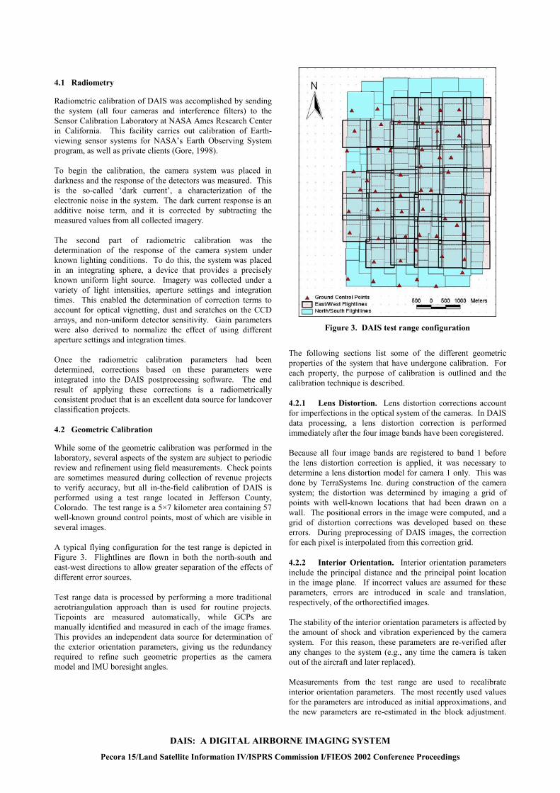
Figure 3. DAIS test range configuration
The following sections list some of the different geometric
properties of the system that have undergone calibration. For each property, the purpose of calibration is outlined and the calibration technique is described.
Once the radiometric calibration parameters had been determined, corrections based on these parameters were integrated into the DAIS postprocessing software. The end result of applying these corrections is a radiometrically consistent product that is an excellent data source for landcover classification projects.
4.2.1
4.2.2
Lens Distortion. Lens distortion corrections account for imperfections in the optical system of the cameras. In DAIS data processing, a lens distortion correction is performed immediately after the four image bands have been coregistered.
Geometric Calibration
While some of the geometric calibration was performed in the laboratory, several aspects of the system are subject to periodic review and refinement using field measurements. Check points are sometimes measured during collection of revenue projects to verify accuracy, but all in-the-field calibration of DAIS is performed using a test range located in Jefferson County, Colorado. The test range is a 5×7 kilometer area containing 57 well-known ground control points, most of which are visible in several images.
Because all four image bands are registered to band 1 before the lens distortion correction is applied, it was necessary to determine a lens distortion model for camera 1 only. This was done by TerraSystems Inc. during construction of the camera system; the distortion was determined by imaging a grid of points with well-known locations that had been drawn on a wall. The positional errors in the image were computed, and a grid of distortion corrections was developed based on these errors. During preprocessing of DAIS images, the correction for each pixel is interpolated from this correction grid.
A typical flying configuration for the test range is depicted in Figure 3. Flightlines are flown in both the north-south and east-west directions to allow greater separation of the effects of different error sources.
Interior Orientation. Interior orientation parameters
include the principal distance and the principal point location in the image plane. If incorrect values are assumed for these parameters, errors are introduced in scale and translation, respectively, of the orthorectified images.
Test range data is processed by performing a more traditional aerotriangulation approach than is used for routine projects. Tiepoints are measured automatically, while GCPs are manually identified and measured in each of the image frames. This provides an independent data source for determination of the exterior orientation parameters, giving us the redundancy required to refine such geometric properties as the camera model and IMU boresight angles.
The stability of the interior orientation parameters is affected by the amount of shock and vibration experienced by the camera system. For this reason, these parameters are re-verified after any changes to the system (e.g., any time the camera is taken out of the aircraft and later replaced). Measurements from the test range are used to recalibrate interior orientation parameters. The most recently used values for the parameters are introduced as initial approximations, and the new parameters are re-estimated in the block adjustment.
DAIS: A DIGITAL AIRBORNE IMAGING SYSTEM
Pecora 15/Land Satellite Information IV/ISPRS Commission I/FIEOS 2002 Conference Proceedings

As with lens distortion, interior orientation parameters are estimated for camera 1 only because of the band-to-band coregistration step. 4.2.3
4.2.4
4.2.5
5.1
IMU-Camera Boresight Angles. Boresight angles are the difference in orientation between the camera body coordinate system and the axes of the IMU. Small errors in the boresight angles lead to systematic errors in translation and rotation of the orthorectified images (for cameras with a larger field of view, significant nonlinear effects may be introduced but these are negligible in the case of DAIS). As with interior orientation parameters, the stability of the boresight angles depends on the amount of shock and vibration experienced. Because it is very rigidly mounted to the camera frame, the boresight angles have been quite stable over the lifetime of the camera system; they do have to be redetermined, however, after the IMU has been removed for maintenance. To determine IMU boresight angles, a block adjustment is performed on test range data. Both ground control points and the perspective center locations are held fixed, while the primarily IMU-derived attitude is given virtually no weight in the adjustment. This gives a solution for the image exterior orientation parameters that is not biased by incorrect boresight angles. To determine the correct boresight angles, the attitude component of the exterior orientation parameters estimated in the block adjustment are compared with those determined by the Applanix postprocessing software. This software contains a module specifically designed for boresight angle determination using this method. Once the boresight angles have been estimated, the IMU data is reprocessed with the correct values. The corrected exterior orientation parameters are re-inserted into the photogrammetric block and the data is reprocessed, this time holding all exterior orientation parameters fixed and treating the ground control points as check points only. The estimated residual errors for these check points then serve as an indicator of the quality of the new boresight calibration.
Time Latency. Time latency is the difference in synchronization between timetags of the GPS measurements, IMU measurements, and image exposures. Any error in determination of this parameter results in a more-or-less constant position error in the flight direction. Because DAIS is almost always flown with the image y-axis within a few degrees of the flight direction, this parameter has an almost identical effect as the principal point y location. Therefore, these two parameters are lumped together and no attempt is made to separately estimate the time latency.
IMU Lever Arm and GPS Antenna Offset. The lever arm and antenna offset are the position differences between the IMU and the GPS antenna, respectively, from the principal point of camera 1 in the camera body coordinate system. These position differences were measured by Space Imaging personnel when the camera was first installed in the plane and are treated as unchanging parameters.
5. ACCURACY EVALUATION
The primary advantage of performing periodic system calibration is that it allows us to use a very simple processing workflow for everyday production work. The position and attitude of each exposure station, as well as geometric
characteristics of the platform, are all treated as known quantities because they have been measured or computed. Aerotriangulation is not necessary to determine or improve any of these parameters. The downside of treating these quantities as fixed is that any errors in the calibrated parameters propagate directly into position error in the orthorectified images. Therefore, it was important to derive an error budget for the system to gain an understanding of the accuracy that can be attained.
Error Budget
The achievable accuracy of orthorectified images from DAIS is a function of the accuracies achieved for calibration of the different components of the system. The major error sources, and their magnitudes, are listed below.
Table 2. Error sources affecting ortho accuracy
Parameter Standard Deviation Band-to-band registration 0.3 pixels Lens distortion 0.3 pixels Principal point 0.3 pixels Principal distance 0.01 mm Boresight angles �roll = �pitch = 3.5 arcsec �yaw = 6.5 arcsec GPS antenna offset �x = �y = �z = 2.5 cm IMU lever arm �x = �y = �z = 1 cm GPS positions �x = �y = �z = 0.3 m IMU attitude �roll = �pitch = 20 arcsec �yaw = 60 arcsec DEM error 5 m
In terms of their effect on the orthorectified imagery, some of these error sources are a function of flying height and thus ground sample distance (GSD) while some are not. Table 3 lists the error budget for some commonly used GSD values.
Table 3. Error budget for common GSD values
Source Error contribution (m)
0.5 m GSD
1.0 m GSD
2.0 m GSD
Registration 0.15 0.30 0.60 Lens distortion 0.15 0.30 0.60 Principal point 0.15 0.30 0.60 Principal distance 0.07 0.13 0.26 Boresight angles 0.03 0.06 0.11 GPS ant. offset 0.04 0.04 0.04 IMU lever arm 0.01 0.01 0.01 GPS position 0.43 0.43 0.43 IMU attitude 0.17 0.34 0.68 DEM Error 0.79 0.79 0.79 TOTAL CE90 (m) 2.05 2.37 3.34
For the parameters in Table 3 that change with the angle from nadir (for example, DEM and camera attitude errors), a mean value of 9 degrees is used. This is slightly more than half the angular distance from the center of the image to the corner. The accuracy specification for DAIS imagery products calls for a CE90 value of 4 meters. It can readily be seen that, given the
DAIS: A DIGITAL AIRBORNE IMAGING SYSTEM
Pecora 15/Land Satellite Information IV/ISPRS Commission I/FIEOS 2002 Conference Proceedings
DAIS: A DIGITAL AIRBORNE IMAGING SYSTEM
Pecora 15/Land Satellite Information IV/ISPRS Commission I/FIEOS 2002 Conference Proceedings
5.2
assumed error budget, this is a conservative estimate. The value of 4 meters CE90 was chosen because it matches the USGS National Map Accuracy Standards for 1:4800 mapping (USGS, 2002b). It also allows us to relax the DEM accuracy requirement, for example, in mountainous regions; a DEM accurate to only 12 m LE90 (standard deviation of 7.3 meters) will still allow the accuracy specification to be met at a GSD of 2 meters.
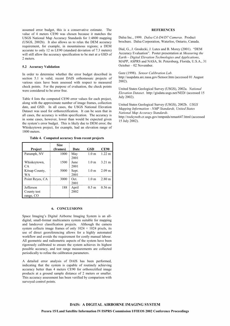
Accuracy Validation
In order to determine whether the error budget described in section 5.1 is valid, recent DAIS orthomosaic projects of various sizes have been assessed with respect to measured check points. For the purpose of evaluation, the check points were considered to be error free. Table 4 lists the computed CE90 error values for each project, along with the approximate number of image frames, collection date, and GSD. In all cases, the USGS National Elevation Dataset was used for orthorectification. It can be seen that in all cases, the accuracy is within specification. The accuracy is in some cases, however, lower than would be expected given the system’s error budget. This is likely due to DEM error; the Whiskeytown project, for example, had an elevation range of 1800 meters.
Table 4. Computed accuracy from recent projects
Project Size
(frames) Date GSD CE90 Parumph, NV 1000 May
2001 1.0 m 1.22 m
Whiskeytown, CA
1500 June 2001
1.0 m 3.21 m
Kitsap County, WA
5000 Sept. 2001
1.0 m 2.09 m
Point Reyes, CA 3000 Oct. 2001
1.0 m 2.80 m
Jefferson County test range, CO
188 April 2002
0.5 m 0.56 m
6. CONCLUSIONS
Space Imaging’s Digital Airborne Imaging System is an all-digital, small-format multicamera system suitable for mapping and landcover classification projects. Although the camera system collects image frames of only 1024 × 1024 pixels, its use of direct georeferencing allows for a highly automated workflow and avoids the requirement for costly manual labour. All geometric and radiometric aspects of the system have been rigorously calibrated to ensure the system achieves its highest possible accuracy, and test range measurements are collected periodically to refine the calibration parameters. A detailed error analysis of DAIS has been performed, indicating that the system is capable of routinely achieving accuracy better than 4 meters CE90 for orthorectified image products at a ground sample distance of 2 meters or smaller. This accuracy assessment has been verified by comparison with surveyed control points.
REFERENCES
Dalsa Inc., 1999. Dalsa CA-D4/D7 Cameras. Product brochure. Dalsa Corporation, Waterloo, Ontario, Canada.
Dial, G., J. Grodecki, J. Lutes and B. Morey (2001). “DEM Accuracy Evaluation”. Poster presentation at Measuring the Earth – Digital Elevation Technologies and Applications, MAPP, ASPRS and NASA, St. Petersburg, Florida, U.S.A., 31 October – 02 November.
Gore (1998). Sensor Calibration Lab. http://asapdata.arc.nasa.gov/Sensor.htm (accessed 01 August 2002).
United States Geological Survey (USGS), 2002a. National Elevation Dataset. http://gisdata.usgs.net/NED/ (accessed 15 July 2002).
United States Geological Survey (USGS), 2002b. USGS Mapping Information - NMP Standards, United States National Map Accuracy Standards. http://rockyweb.cr.usgs.gov/nmpstds/nmas647.html (accessed 15 July 2002).