Embed Size (px)
Citation preview

IINNDDEEXX
ESApro - P&ID 1
ESApro P&ID
Release V7
USER MANUAL (rev. 6.0)
ESAin Srl Via Montevideo 15/3 16129 GENOVA
Tel. 010/311544 Fax. 010/313606 http://www.esain.com
E-mail: [email protected]
This publication may not be reproduced in any form, by any method, for any purpose either entirely or in part.
AutoCAD is a registered trademark of Autodesk Inc.

IINNDDEEXX
ESApro - P&ID 2
1. INTRODUCTION ................................................................................................................... 3 2. ESAPRO-P&ID AND AUTOCAD ............................................................................................... 4
2.1 THE USER INTERFACE ............................................................................................ 4 3 P&I DIAGRAM DRAFT ......................................................................................................... 6
3.1 PIPE CLASS .............................................................................................................. 6 3.2 LINE ........................................................................................................................... 7 3.3 LINE MANAGER ...................................................................................................... 13 3.4 LINE MANAGEMENT ............................................................................................... 19 3.5 INTERACTION BETWEEN COMPONENTS AND PIPING CLASS ......................... 24 3.6 SYMBOL INSERTION, GENERALITIES .................................................................. 26
3.6.1 SCALE FACTORS ................................................................................................... 27 3.6.2 LINE COMPONENTS INSERTION AND ALIGNMENT............................................ 28 3.6.3 VALVES INSERTION PECULIARITIES ................................................................... 32 3.6.4 INSTRUMENT INSERTION ..................................................................................... 33 3.6.5 REDUCERS ............................................................................................................. 35 3.6.6 EQUIPMENT AND NOZZLES .................................................................................. 35 3.6.7 SYMBOLS ................................................................................................................ 36
3.7 EDIT SCHEME ......................................................................................................... 38 3.8 COMPONENT TAGGING ........................................................................................ 40 3.9 LINE TAGGING ........................................................................................................ 46 3.10 ISA STANDARD COMPLIANCE .............................................................................. 48 3.11 KKS STANDARD COMPLIANCE ............................................................................. 48 3.12 ANNOTATIONS ....................................................................................................... 50 3.13 OBJECT PROPERTIES ........................................................................................... 52 3.14 CROSS REFERENCES AND MULTISHEET ........................................................... 54 3.15 WORKING OPTIONS ............................................................................................... 58 3.16 SIZES AND TITLE BLOCKS .................................................................................... 62
4 DATABASE MANAGEMENT AND BILLS OF MATERIALS ................................................ 63 4.1 SYMBOL LIBRARY MANAGEMENT ....................................................................... 64 4.2 PIPING CLASSES MANAGEMENT ......................................................................... 67 4.3 PROJECTS MANAGEMENT ................................................................................... 73 4.4 BILL OF MATERIALS ............................................................................................... 78 4.5 MANAGEMENT OF BILL OF MATERIALS MODELS .............................................. 81 4.6 FIND DUPLICATE TAGS ......................................................................................... 84 4.7 NOMINAL DIAMETER TABLE ................................................................................. 85 4.8 INSTRUMENT TYPE LIBRARY ............................................................................... 85 4.9 CUSTOM LIBRARIES .............................................................................................. 86 4.10 INSULATING CLASS LIBRARY ............................................................................... 87 4.11 OTHER TABLES ...................................................................................................... 88 4.12 UTILITIES ................................................................................................................. 89
A. CUSTOMIZATION PROCEDURES .................................................................................... 95 A.1 SYMBOL ARRANGEMENT ..................................................................................... 95 A.2 GRAPHIC SYMBOL DRAWING ............................................................................... 97 A.3 TITLE BLOCK CUSTOMIZATION .......................................................................... 101

IINNSSTTAALLLLAATTIIOONN
ESApro - P&ID 3
1. INTRODUCTION
ESApro-P&ID is an AutoCAD application which strongly enhances the activity of process diagrams drawing and material list generation. Graphic and data management modules perfectly complement each other so to create an efficient environment for the easy control of the whole work. The plant drawing is easily made through mechanisms of line management and automatic component positioning that set the designer free of concentrating on the conceptual part of his work.
At the same time characteristic data are associated to the plant elements in automatic and controlled way under the supervision of Piping Class. Manual entry is not needed.
Once finished the diagram draft, material lists may be extracted from the drawings according to templates freely prearranged by the user. Material lists may be directed to screen, printer or to ASCII, Excel and Access files.
A number of utility programs for Piping Class and Project management as well as for database maintenance are available. Other programs are dedicated to the user’ symbols customization.

PP&&IIDD DDIIAAGGRRAAMM DDRRAAFFTT
ESApro - P&ID 4
2. ESApro-P&ID and AutoCAD
In the following paragraphs we’ll examine the program functions dedicated to the graphic draft of a process diagram and those that contemporarily enable to enter all data related to the plant elements. These data will be used to generate the material lists.
2.1 THE USER INTERFACE
The installation program creates two different working environment, one called”ESApro PID V7” and the other “ESApro V7 Classic”, in the former case the interface being Ribbon.
In the latter are Pull down Menus and Tool bars. In all cases the interface of ESApro P&ID is sided by the AutoCAD interface which is not modified

PP&&IIDD DDIIAAGGRRAAMM DDRRAAFFTT
ESApro - P&ID 5
There also is a dedicated toolpallet.

PP&&IIDD DDIIAAGGRRAAMM DDRRAAFFTT
ESApro - P&ID 6
3 P&I DIAGRAM DRAFT
In the following paragraphs we will widely explain the concepts and the procedures for the realisation of a P&ID layout under the control of Pipe Class
3.1 PIPE CLASS
The creation of a P&ID layout is controlled by Pipe Classes, the lists of the available components for a project. To a new line must be assigned a class and then all its defined data will be inserted into the related line and components. The Class Pipe enables the insertion on the line of the components allowed in order to simplify the procedure. Instruments and machinery are not influenced by this operation.
The aims of Class are:
• To build up a number of data related to the allowed components only (ex: Low Pressure Steam).
• To transfer automatically the predefined data to the allowed components.
• To prevent the insertion of unwanted data.
For more details on the creation andthe maintenance procedures of a Pipe Class see chapter 4.2 “Pipe Class Managment”

PP&&IIDD DDIIAAGGRRAAMM DDRRAAFFTT
ESApro - P&ID 7
3.2 LINE
This is the fundamental command for the generation of P&ID under the control of Piping Classes. It is launched from the P&ID menu by the keyboard shortcut LL or by the related toolbar. This opens a dialog window for the definition of the line data.
The first page is identified by the “Identifying and Descriptive” tag and contains the identifying data of the line, Class, ND, and also some descriptive parameters.
In order to create a new line it is necessary to enter a Line Number, a Class and a Nominal Diameter, all highlighted in light blue. Such data are used by the program to extract all the pre-defined data in Class. The Line number together with Unit/System and Branch determines its identification name which must not be replied; it can contain a whatever combination of alphanumeric characters and determines the continuity of the line which means that has in common all parts and components shared by the line . The Fluid Type can eventually be a

PP&&IIDD DDIIAAGGRRAAMM DDRRAAFFTT
ESApro - P&ID 8
part of a line identification data otherwise it must be considered just as a descriptive data. Unit/System , “Number” and “Fluid Type” are displayed on pull down menus or filled in. The “Branch” field can only be filled in.
When it is necessary to continue an existing line its identification name and all other data must not be changed. To this purpose select “Continue Line ” in the creation mask and draw the line starting from one end where all the necessary data will be acquired , the flux direction included.
When the “Unit/System”, “Number” and “Branch” data of a new line will be the same ones of a pre-existing one the program sends an “error” message. However, the generation of two lines with the same name is allowed as it can be necessary in some cases. For example when two parts of the same line are on different drawings of a multi sheet P&ID , or two separated parts of the same line generated by editing procedures and subsequently reconnected in the end . Also when it is necessary to continue the same line but with different characteristics. When two parts of the same line are separated geometrically it is possible to maintain the logic continuity with the aid of tools which will be described further on. Thus, excluding the previously explained cases, two parts with the same identifying data and separated, physically or logically, are a mistake of duplication or separation. Then the set of all parts and components of a line with an identification data is a continuous chain of elements logically connected, unifiliar, with a direction , one starting point and one and only end.
Two pull down menus are available in the “Class and ND” section . They display the Classes of the system and the related nominal diameters.
The mask in the “Descriptive” section contains the “Service”, “Area” and “Nozzle From /To” fields. The “Service” field as well as the “Fluid Type” displays the values already present in the system . The “Nozzle From” and the “Nozzle To” fields contain the tags of the nozzles connectected by the line. And they are not the “From” and “To” tags of the equipment or of the line-ends of the main line. They all have to be filled in by the user and do not need the presence of the drawings of the nozzles., which can be inserted as symbols but will not affect the logic of the program and the related “Nozzle List” whose data will be taken from the predefined fields on the creation mask of the line. Therefore the line is connected to the line as “From” and “To” to the

PP&&IIDD DDIIAAGGRRAAMM DDRRAAFFTT
ESApro - P&ID 9
lines or to the equipment : But the names of the connected nozzles are inserted in the due fields even if they are not drawn.
“Line status“ is a parameter representing the working progress of the line. The various possibilities are: “In progress”, “Revision”, “Supported”, “Stress Analysis”, “Generated sketch” and “Finished”. Some status are obviously more appropriate during the line generation in ESApro Piping 3D with which shares the line’s definition mask.
In the second page, identifiable by “Process and Insulation” are contained Pressure, Temperature, Insulation, and the tracing and jacketing data. The insulation data are made of a tag, a material and a thickness. The Insulation Class are defined in the library of the “Specifics Management” environment described further on. Once selected a class all the reletad data and the predefined thicknesses will be loaded into the line’s creation mask .
In the third page, identified by the “Custom and Notes” pull down menu, up to eight fields are available to the purpose. The “Custom 1-8” tags can be customized in the “Specific Management” environment as it will be explained further on.
Once data are set, a broken line representing the pipe line can be drawn. The program takes care of setting the object snaps “End”, ”Mid“, ”Near”, “Quadrant” and “Perpendicular” in order to help the drafting and the connection to pre-existing graphic elements. If a line is started or ended on another line or equipment or different P&ID object, this last one will be highlighted with a cross to mean that its tag will be stored into the line respectively “From” or “To”. These information are also displayed in the command line together with the Line Number. During the operation the symbol pointing out the line direction displays and the various line segments are highlighted These marks are temporary and are erased whenever an operation causes a screen refresh. In case of error of the line drawing the “Undo” option is available for going back to the previous point. Only rectilinear segments are allowed. Curved pieces of pipeline must be approximated with a series of short straight segments.

PP&&IIDD DDIIAAGGRRAAMM DDRRAAFFTT
ESApro - P&ID 10
When the automatic numbering is enabled in the “Project Options”, described further on, the program automatically allocate a progressive number to each new line. It is anyhow allowed to overwrite it with a generic alphanumeric code. The line number box has a pull down list that contains all the already used codes; it can be useful as a guide before assigning a new code, or for picking up an existing code to re-use it for a line branch as described next. If the user respects the convention stating that the line number of a branch changes with respect to the origin line, the consequence will be that each line will have unique “From” and “To”. Otherwise if the user prefers that the main line and its branches have the same line number, the branch concept must be used. In this case the same line number will be allocated both to the main line and to its branches but their branch numbers will have to be different (the box at the right of the line’s number )
To this purpose the “Branch” field at the side of the “Line Number” must be filled with a whichever alphanumeric string. The distinction between main line and branches, that must always exist, is ensured by the combination of the two codes while the same Line Number cause them to be recognized as a unique homogeneous group. In this case a set of lines may have more “From” and “To” which will be considered in the line list with the following criteria: the connections among lines belonging to the same group are ignored while the tags of the external objects the various branches are connected to, will be taken as “From” or “To”, depending on the direction of the branches themselves. The same concept applies to the System (in the box at the left of the line’s number). In two different line Systems two lines can exist at the same time with the same number and branch. If the user whishes to insert the “Fluid Type” option this will have the same function as “System” that is to say that two lines with different fluids are allowed to bare the same line number. The “Area” data has though a different meaning, as it indicates the geographical area of a plant the line belongs to. It is for this reason that it will change when passing through different parts of a plant even if System+Number+Branch will remain the same.

PP&&IIDD DDIIAAGGRRAAMM DDRRAAFFTT
ESApro - P&ID 11
In the figure shown you can see a set of lines to which an identical line number 001 has been assigned. On the contrary different branch codes, not displayed neither on the drawing nor on the documentation generated by the program, are assigned to various pieces. On the line list you can see, besides the other data, “From” and “To” derived from the flux direction. The criteria for assigning the line number depends on the company standard and for this reason they are very different from case to case. The program does not set particular conditions except for the creation of a branch where the above described concepts must be kept in mind. If a line is built by joining two contiguous pieces with different Line Numbers you may see that the continuity is interrupted. The main tool for visualizing in particular configuration, direction and connection correctness of a line is command “Show Line”. Whenever a segment of a line is touched the same marks that were visible at the moment of its creation will be displayed. On the contrary the “Object Properties” command must be used in order to modify the information stored on a line. Both commands are described in detail at par. 3.3 and 3.11. Symbols indicating the direction of the flux on a line will automatically be inserted provided they are enabled on the Working Options control panel described in the follow- up. These symbols are updated as a consequence of modification operation (component insertion or deletion) or flux direction inversion which may be performed through the “Invert Line“ command. By means of the “Insert Flow” command flux direction symbols can also be inserted manually where the automatic procedure does not provide for it, while they can be deleted through the usual AutoCAD “Erase” command.
While creating a line, a possible existing equipment is automatically connected provided that the line physically touches the equipment. In this case the equipment is marked with a green or yellow X to highlight

PP&&IIDD DDIIAAGGRRAAMM DDRRAAFFTT
ESApro - P&ID 12
the fact that it becomes the line “From” or “To”. Commands for connecting lines, equipment or other P&ID elements to a pre-existing line will be described in the following paragraph.
A branch can start from the common vertex of two segments which are part of a line. As a matter of fact this configuration is equivalent to a branch starting from the middle of a straight segment. This second representation is suggested because it directly distinguishes the main line from the branch without the need to mark the lines in any way. In the figure shown below two equivalent configuration are displayed. The one on the right is more clear.
Generally no more than two lines can start or converge to one knot. In case that more than two lines are compelled to start or converge to a knot, the previous insertion of a symbolic manifold, called Connection, is needed. The Connection is a small black ball that may be freely positioned anywhere on the drawing or at a line end; in this case it automatically connects to the line itself. Once positioned Connection gives the possibility of connecting lines to its quadrants or in general to its boundary. If the lines are two we refer back to the previous case therefore the Connection symbol could be omitted. Flow directions can directed into the knot or out of it . Furthermore lines may differentiate one from each other with the previously described mechanism of the branch code. Also in this case, like for the inner connections of lines belonging to a group with the same line number, the knot is ignored when computing “From” and “To”. Entities on the other side of the knot are connected if they have a different line number or further on ignored if they have the same line number, until an outer line or equipment is reached.
PP&&IIDD DDIIAAGGRRAAMM DDRRAAFFTT
ESApro - P&ID 13
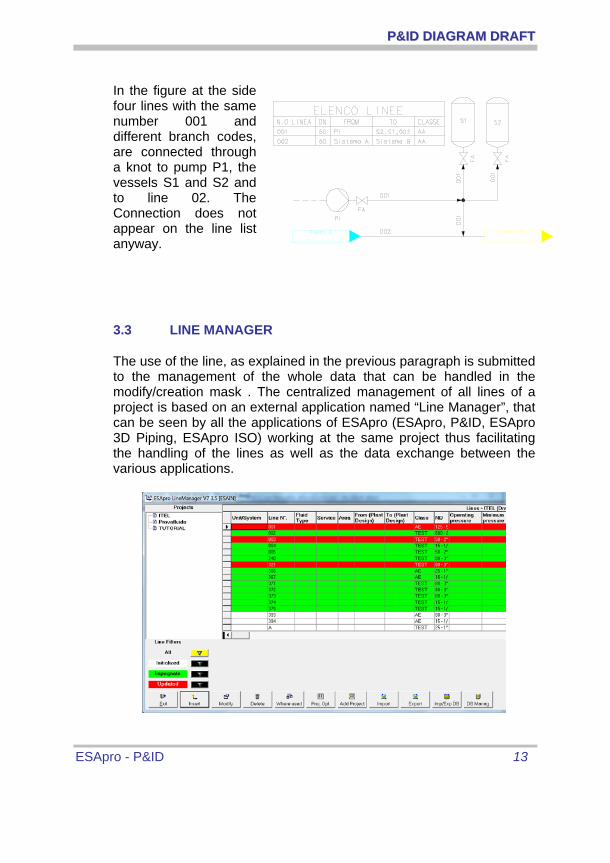
In the figure at the side four lines with the same number 001 and different branch codes, are connected through a knot to pump P1, the vessels S1 and S2 and to line 02. The Connection does not appear on the line list anyway.
3.3 LINE MANAGER
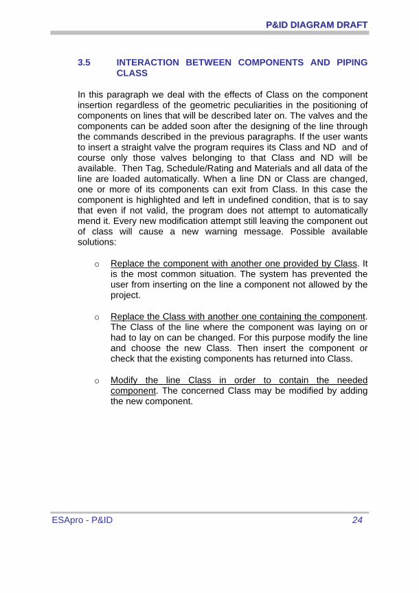
The use of the line, as explained in the previous paragraph is submitted to the management of the whole data that can be handled in the modify/creation mask . The centralized management of all lines of a project is based on an external application named “Line Manager”, that can be seen by all the applications of ESApro (ESApro, P&ID, ESApro 3D Piping, ESApro ISO) working at the same project thus facilitating the handling of the lines as well as the data exchange between the various applications.

PP&&IIDD DDIIAAGGRRAAMM DDRRAAFFTT
ESApro - P&ID 14
Two operation modes are available: first open one of the two through “Working Options”
• Lines List from “Line Manager” or Predefined
• Lines List by “Graphics”
Predefined Lines List Mode
This system comes useful when a Supervisor handles the project and also in case of plant with great quantities of lines and drawings(ex: P&ID multilayers, shared 3D mouldings or manual creation of isometric sketches) . In this working mode the line list is predefined by the Supervisor, who defines quantities and lines . The users are bound to use those lines lists when creating a new line .
In this phase the usual mask is available where the users can handle only those lines inizialized by “Line Manager”. In this case the background tone of the line becomes light blue . Only the data contained in “Parts Data” are allowed to be modified as they can change along the line (ex: Area, Class, ND, Insulation....) The change of data in the “General” option is not allowed . The user then is free to create a line with diameters differing from the default in “Line Manager” and also with a different “Insulation Class”. Viceversa the user is not allowed to modify “Fluid Type” or “Prroject Pressure” whose choice is up to the Supervisor.
In the following diagram are available a summary of lines data , and the two tipologies they belong to as well as the environment where they can be modified.

PP&&IIDD DDIIAAGGRRAAMM DDRRAAFFTT
ESApro - P&ID 15
Field Type To be modified in
Unit/System General Line Manager
Line Number General Line Manager
Branch General Graphic , branch are parts of the main line..
Area Parts Graphic
Class Parts Graphic
ND Parts Graphic
Service General Line Manager
Fluid General Line Manager
From/To (3DP/ISO only)
General Graphic for ESApro P&ID, Line Manager for ESApro 3D Piping and ISO.
Nozzle From/To Parts Graphic, a line can have more than one nozzle connected to branchs.
Line Status General Line Manager
Presssures General Line Manager
Temperatures General Line Manager
Insulation Class Parts Graphic
Tracing/ Jacket Parts Graphic
Customs/ Notes General Line Manager.

PP&&IIDD DDIIAAGGRRAAMM DDRRAAFFTT
ESApro - P&ID 16
Lines List by “Graphics" mode
This mode does not necessitate the intervention of a Supervisor. The line data are defined in the creation/modify mask already described. The procedure then is exactly the same as for the previous versions of ESApro, where “Line Manager” was not included. Only, the data of the line here are defined in a graphic environment and feed anyway the centralized data of “Line Manager”. Two different users then will be able to work at the same line without the risk of creating clashing data . But the “General “ fields can be modified and as a consequence each user will be entitled to modify the line through the “Modify Data” option or through the “ESApro Line Manager” application as it will be described further on. In case of a line already iniziailized in “Line Manager” the background colour of the line creation form turns to light blue, otherwise it will remain white.
“Line Manager” can be accessed through its button in Ribbon, on the P&ID V7 menu or on the Toolbars. Its mask will provide the name of the data base and the current mode (“Line Manager or “Graphic”) on the column on the left. On the right is displayed the list of the lines and all the related data fields . The lines have different colours according to their status. Their status and only that is displayed in the section “Line Filters”
• White, line inizialized in “Line Manager” or in “Graphic” In the first case the line is inizialized by the insert button, while in the second case as soon as the creation process begins . In any case the line creation mask is just the same.
• Green, engaged line. A line is always considered engaged when used in a drawing and appears in the line library of the project. The procedure is carried out through the “Data Extraction” command “ which also will save the document. Therefore the “Line manager” is not updated in real time.
• Red, modified line The line can be modified through the “Modify” command in Line Manager or in Graphics through the “Modify Data”, as described further on. Bare in mind that the same line can be used in many drawings which will need to be updated. In fact when this happens the colour of the line turns from Red to Blue. When modifying parts of a line it is not necessary to update nor the drawings or the colour of the line. The variation of a white line not

PP&&IIDD DDIIAAGGRRAAMM DDRRAAFFTT
ESApro - P&ID 17
engaged does not imply the change of colour as it has not been used yet in any document. The drawings are updated, once open and when returning to the drawing from “Line manager”, or through the “Batch” procedure as it will be described further on. When all the drawings are updated the line will return into “Line Manager” and its colour will turn to Green.
Let’s consider now the details of the commands in “Line manager”
Exit: terminates the current session of “Line Manager”
Insert: displays the creation mask of a new line. The data fields of ”Part” and those of “General” are highlighted with different colours. To create a line means to inizialize it and its colour is white. When creating a new line, if filled with data already present, the program will send an error message.
Modify: displays the same mask used for the creation of a new line. When modifying a white un-used line none of the drawings is updated and the colour remains White. When a line is engaged (Green) its colour changes only if a data in “General” is changed. The “Part” data are considered as default and can be modified locally in the drawings. Mind that when cancelling a modification which has turned the line from “Green” to “Red” it remains “Red”, as the line before the cancellation might have been used by somebody else on another document.
Delete: erases a line in “Line manager” only if the line is engaged, but if it is not it does not. Mind that once finished the project the lines in White colour can be deleted as not used anywhere in the project.
Where used: displays a report with the documents of the project containing the modified lines in colour red. The drawings to update are found when starts the saving procedure in “Line Manager” through the “Project Options” mask that will be described further.
Project Options: displays the “Project Options” window which will be described later on.
Add Project: allows the definition of a new project without going through the “Project” environment, where the procedure is carried out and that we will explain further on.

PP&&IIDD DDIIAAGGRRAAMM DDRRAAFFTT
ESApro - P&ID 18
Import/Export Line: defines an external Excel file to import/Export into “Line Manager” a list of lines from. Data base structure must comply with a template under the name: Import_Lines.xlsx in the folder ...\ESApro V7\Common.
Imp/Exp DB: displays the “Import/Export from Database” window which will be described later on.
Database Management: allows the access to the “Database Procedure” as described further on.
As already said on the desktop is displayed an icon (P&ID Update Batch) that launches the update of the drawings of a project following modifications of lines data contained in “Line Manager” . Once chosen a Database, pressed the “Database management” command, and also chosen a project will be displayed all those drawings that need to be updated. Other drawings can be selected and forcibly updated. The “Exit” command terminates the procedure. “Update Dr.“ launches the update and “Database Management”opens the application “Database Management" described further on.

PP&&IIDD DDIIAAGGRRAAMM DDRRAAFFTT
ESApro - P&ID 19
3.4 LINE MANAGEMENT
At the Line of the P&ID menu or of the Tool Bar or Ribbon are grouped some commands for the line maintenance.
o Show line, is the main command to highlight the line’s course and for the diagnosis of the continuity of the line considered as a sequence of pipes and components. Each piece of pipe and each component keep the address of its contiguous elements. These information, together with the same Identification Line Number, ensure that the line is considered as a chain of continuous elements having a well defined path from “From” to “To”. The “Show line” command requires the selection of a part of a line and then highlights the whole line. At the line ends two symbols appear, a green box and a yellow arrow that shows its start point, end point and direction. Whether the line starts or ends on other lines or equipment or components, this command displays respectively the line number or the equipment or component tags connected as “From” or “To” on the command line. Furthermore “From” and “To” are highlighted on the drawing with an “X” that disappears at the first screen re-drawing. Further operations and material list extraction can be compromised if the command terminates with an error message or does not display the expected line or if “From” and “To” are disconnected. In this case the following commands of line mending and maintenance are provided:
o Lines grouping: this utility command enables an AutoCAD selection of all parts and entities of a line. It is like a switch that activates or dis-activates the process. An option is available to include all the branches with the same number of the main line. The command can be used for all pourposes when selecting a whole line.
o Piping Class changing, is a symbol that can be placed between two connected lines that have different Classes. Automatically obtains the names of the classes and displays them next to the symbol. In case of updating the names of the classes are automatically synchronized. Tthe

PP&&IIDD DDIIAAGGRRAAMM DDRRAAFFTT
ESApro - P&ID 20
symbol can be positioned above or below the line which it is inserted.
o Object Properties, this command is the main tool for examining and modifying the content of each P&ID object. In this context we’ll describe its effect upon the lines. For a full description see Chapter 3.11 “Object Properties”. When you click on any line piece, the same window used for its creation is displayed. Once made the modifications, they will be applied to all the line pieces with the same line number and to all the components laying on them. If on the line there are one or more reducers, they divide the line into separate parts. The same effect is generated by symbols of reference from a sheet to another one. Then the modification of a line laying on more sheets is limited to the current visible sheet; the reason for that is to compel the user to verify the modification effects on the line sheet by sheet. Anyhow that part of a line affected by the modification is highlighted on the drawing. If line parameters changing causes pipes or components exiting from Class then they will be highlighted in red. No mark means that all components belong rightly to Class. If instead of clicking on a line or component the user presses “Enter” the modality of selection and modification of single line pieces and components is set. In this way it will be possible for example to change the material of a line piece going through a corrosive environment or, if needed, its Line Number or Class.
o Invert line, simply inverts the flow direction of a line. “From” and “To” will be reciprocally exchanged. The effect of this command can be seen with “Show line”. Possible flow direction symbols will be automatically updated.
For the above mentioned reasons, the deletion of a line element through standard AutoCAD commands would cause the reference to a no longer existing object to remain into the contiguous elements. The line continuity would be spoiled. In fact the program intercepts every call to the AutoCAD “Erase” command and if applied to P&ID elements it provides the required adjustments. The “Erase” command, suitably modified, also provides some useful functions. If a valve or a component are erased the gap is automatically filled. In case of three-

PP&&IIDD DDIIAAGGRRAAMM DDRRAAFFTT
ESApro - P&ID 21
way valves also the branch gap is filled. If components lay at the end of a line they are simply removed and their reference I s deleted from the remaining components. Also in case that a line piece is erased in order to subsequently modify the line path, the references to the removed piece are corrected. If an equipment component is erased all the connected lines are corrected.
o Mend: shows the options “Adjust” and “Synchronize”. The first one corrects a line reference to a no more excisting object. If a line or a component have a wrong reference no operation can be performed on them. In this case with the “Mend” command touch the line end pointed out by a small magenta square. The wrong reference is removed and the line can be modified again. If the line shows problems in recognizing connections the “Synchronize” option can be used. This option requires the ordered selection in the flow direction of all the line components and eventually of "From" and "To" elements. Eventually discordant directions are removed and the line is correcly reconnected.
o Connect Line, is used to connect lines and equipment to an existing line. As previously mentioned if a line starts or ends on another pre-existing line or equipment the latter will be stored into line “From” or line “To”. If the line or equipment are inserted afterwards the reference must be set by the “Connect Line” command that requires to approximately select the line end and the element to be connected to.
Once performed this operation, you can verify with the “Show Line” command that the connected line or equipment have been stored in “From” or “To”.

PP&&IIDD DDIIAAGGRRAAMM DDRRAAFFTT
ESApro - P&ID 22
The copy of parts of a diagram P&ID, is a process activated by the AutoCAD “COPY” and “MIRROR” commands, and also by the “cut and paste” functions between two drawings and by the insertion of a block containing P&ID objects after its explosion.
Command “ARRAY” is not managed and then cannot be used on P&ID objects. In general the purpose of such commands is to enable the duplication of any part of an existing plant but do not be misled when inserting valves or components on the lines as they need to be entered through the commands the program provides. After the standard operation of selection and positioning, the program takes control to rename all the new lines in order to prevent the generation of duplicated line numbers.
Then it provides the reconnection of new lines and equipment. In case the copy does not include all the old line components, the new one will be suitably corrected in order to acknowledge the disconnected parts and to ensure their congruency. On the mask provided are listed all the lines to rename. They are temporarely named “#” followed by the old number or , when the option “Automatic line numbers” is enabled, the first available number. It is up to the user to accept such procedure and change it with the command “Modify Data”, or as an alternative to assign the new number. As said before the “System”, “Fluid” and “Branch”

PP&&IIDD DDIIAAGGRRAAMM DDRRAAFFTT
ESApro - P&ID 23
fields are included, as the new number can be obtained also by their composition.
The copying process does not take into account either the branches that maintain the original value and code or the possible equipment, instruments and other components. Their code modification will be made, if necessary with the “Object Properties” command.
PP&&IIDD DDIIAAGGRRAAMM DDRRAAFFTT
ESApro - P&ID 24
3.5 INTERACTION BETWEEN COMPONENTS AND PIPING CLASS
In this paragraph we deal with the effects of Class on the component insertion regardless of the geometric peculiarities in the positioning of components on lines that will be described later on. The valves and the components can be added soon after the designing of the line through the commands described in the previous paragraphs. If the user wants to insert a straight valve the program requires its Class and ND and of course only those valves belonging to that Class and ND will be available. Then Tag, Schedule/Rating and Materials and all data of the line are loaded automatically. When a line DN or Class are changed, one or more of its components can exit from Class. In this case the component is highlighted and left in undefined condition, that is to say that even if not valid, the program does not attempt to automatically mend it. Every new modification attempt still leaving the component out of class will cause a new warning message. Possible available solutions:
o Replace the component with another one provided by Class. It is the most common situation. The system has prevented the user from inserting on the line a component not allowed by the project.
o Replace the Class with another one containing the component. The Class of the line where the component was laying on or had to lay on can be changed. For this purpose modify the line and choose the new Class. Then insert the component or check that the existing components has returned into Class.
o Modify the line Class in order to contain the needed component. The concerned Class may be modified by adding the new component.

PP&&IIDD DDIIAAGGRRAAMM DDRRAAFFTT
ESApro - P&ID 25
The modification of Piping Classes already in use must be carried out with care as in some cases the P&ID is not automatically updated. Typical situations are:
o Modification of class data of a component.(ex: materials) All components of that type are automatically updated.
o Modification of class data of a pipe. All lines made with that class are automatically updated. For each drawing the possible line tags must be updated with the “Update Tags” command.
o Addition of a component to the class. No need for updating as no component of that type can exist on the drawing.
o Deletion of a component from the class. All components must be removed from the drawings. The “Drawing check” command displays all the components out of class.
o Deletion of a class. The program prevents the deletion of classes referring to one or more drawings.
Furthermore we point out that a Piping Class could have been used on drawings belonging not only to the same project but also to other ones. In this case its modification or deletion could affect more projects, either already filled or still in progress. Therefore we suggest to use a different database for each project as it will be described further on. In this way independent environments may be created where Piping Classes are not affected one by the other.

PP&&IIDD DDIIAAGGRRAAMM DDRRAAFFTT
ESApro - P&ID 26
3.6 SYMBOL INSERTION, GENERALITIES
Through the dialogue window “Layer Management” the user can determine the colour and the layer of the P&ID elements . The lines are built on a system called “PID LINES” followed by System, or Line Number or the fluid type. As an alternative they can be designed on the current layer or in a predefined layer. The layer’s colour is assigned by the colour default available further below. The lines match the values of the layers they belong to and so do the valves and the lines’ components, but the last ones can hold a different colour . Al the other elements of P&ID as Instruments, Instruments Line and Signal Lines are designed on the current layer or the fixed layer. Their colour can be chosen. Also an explicit colour may be applied to lines. Its value must be set in the “Working Options” dialogue box and is displayed whenever the line thickness is switched on in AutoCAD. In case lines belonging to different layers and having different colours, linotypes and thickness exist on the drawing, the program provides to respect these specifications at the component insertion, so that the user will not have to worry about it. Each property described above has just an aesthetic purpose and doesn’t affect the P&ID system logics.
The insertion of a component can be carried out through the Menu, Toolbar and Ribbon interfaces.
For those elements under the control of the pipe Class (Valves and line Components) it is required to select a line before the choice of a list of

PP&&IIDD DDIIAAGGRRAAMM DDRRAAFFTT
ESApro - P&ID 27
allowable components. For the other elements (regulating Valves, Instruments and Equipment) are available specific dialogue windows..
In order to be inserted a component needs to be picked up from the current library through the related dialogue window and then positioned. The P&ID menu gives access to all the library components. Almost all procedure commands implement the automatic repetition. Therefore components may be inserted one after the other in sequence and it is necessary to press (ESC ro ENTER) to exit the command.
3.6.1 SCALE FACTORS
There are two scale factors for controlling the component dimensions. Setting is made through the “Print scale” item into the “Working Options” dialogue window (see paragraph 3.13).
The first one, called “Print scale”, scales all the graphic components in order to fit a particular requirement. For instance if the P&ID diagram is drafted on an existing lay-out to be printed in scale 1:100, setting “100” as scale factor this command forces the program to enlarge a hundred times title block, symbol and text dimensions.
When the drawing is printed in scale 1:100, everything will go back to normality. Obviously the “Print Scale” must be set at the start of the drawing while further variations are not necessary.
The other factor, “Ask X and Y scale”, allows to individually scale and if needed distort a symbol with the due respect for its original dimensions. At the symbol insertion the program requests the two multiplying factors for X and Y dimensions and then continues . After the insertion remember to switch off the check box in the “Working Options” window in order to prevent further continuous requests. Furthermore a lot of equipment can directly be scaled or stretched through the greeps.

PP&&IIDD DDIIAAGGRRAAMM DDRRAAFFTT
ESApro - P&ID 28
3.6.2 LINE COMPONENTS INSERTION AND ALIGNMENT
The program offers a function for the automatic alignment of valves, components placed in-line instruments and reducers, which permits their positioning in the nearest point available on the line. While dragging on the lines, without clicking, the program shows in real time the component’s state. In detail:
• The component automatically aligns according to the line direction.
• Inside the AutoCAD’s cursor distance range, the component is attracted by the line. Besides it springs on lines and components end and mid points. These points are confirmed by a small yellow circle called PSnap. Its dimension is equal to the AutoCAD selection cursor’s and can be consequently regulated. Angle and three way valves spring at the lines intersections.
• If the class requests it, the component visualizes the threaded, flanged, socket-weld style when the line is touched.
• If the component is positioned on a instrumental line, it is reduced to half its original symbol dimension.
• Check valvs, components or instruments which request that, are automatically orientated to the direction of the line flow. Changing the flow direction also changes the components orientation.
• In any case of wrong positioning or non correspondence to the line’s class, a red cross

PP&&IIDD DDIIAAGGRRAAMM DDRRAAFFTT
ESApro - P&ID 29
appears on the component to warn the user. In this case the left clicking is ignored. It is also ignored when the component is inserted in out of the line.
To terminate the insertion of a component left click with the mouse. Immediately after that it will be possible to insert a new component and so on. To terminate the process press ESC or ENTER. In any case the component takes its characteristics from the line itself and from the Class, just like DN, other descriptive data and representation attributes like colour and layer according to the previously explained rules. Afterwards the line is automatically trimmed and the component inserted into the gap. The command “Object Properties” (detailed below) permits the inversion, the rotation, the shift and the duplication of a valve or component in the line, after it has been inserted.
Insert command vary according to the typology of the component.
Valves and straight components show the following options at the command line:
Select a Line, a Valve to replace or (Alignment /Invert /Rotate /reFerence) <Esc or Enter to
Gli strumenti in linea e le riduzioni non richiedono la scelta della linea preventiva per l'identificazione della Classe tubazioni, non ne sono sottoposti, ma per il resto condividono le opzioni e la tecnica di inserimento di valvole e componenti.
In-line instruments and reductions do not require the previous choice of the line to identificate the pipe Class, but they share the same options and insertion technique of valves and components.
Unusually these options, put in round instead of square brackets, do not need the pressing of ENTER after the capital letter.
Alignement, shifts the insertion point of the valve or the component repeatedly to the midpoint, to the left or to the right. Here a cross-shaped cursor is

PP&&IIDD DDIIAAGGRRAAMM DDRRAAFFTT
ESApro - P&ID 30
shown. This control is useful to align a component to the other or at the end of a line, with the help of PSsnap.
Invert, switch the right side with the left side of the valve or the component. It is useful to orientate a component which does not automatically align to the flow direction, like a blind flange or a reducer. Check valves or preset components instead, align themselves automatically to the flow direction.
Rotate, rotate the valve or the component of 180° around the line. It is useful especially for the most bulky control valves, when the preset positioning interferes with already existing parts.
reFerence, aligns the valve or the component to a point on another line. The object has to be previously hooked to the destination line while pressing “F”, otherwise a warning message is sent by the program. It is therefore possible to select the alignment which is confirmed by PSnap. In most cases the point will belong to a similar object already put on a parallel line, but generally any selected point is projected onto the line where the component to be aligned lies. The program visualizes a guide and shows the alignement in real time.

PP&&IIDD DDIIAAGGRRAAMM DDRRAAFFTT
ESApro - P&ID 31
The “Edit component” command, which can be found in drop-down menu, toolbars and ribbon offers the following modify options about valves, components and in line instruments, already lying on the lines:
Select an option [Invert /Rotate /Move /Duplicate] <Terminate>:
Invert, switch the right side with the left side of the valve or the component. Not those that align themselves automatically to the flow direction.
Rotate, rotate the valve or the component 180° around the line.
Move, allows to reposition an existing valve or component. The line is closed again and the component can be replaced by using the same “line component insertion” method. If the component is compatible the new position can also be found on another line. The component will take its properties from the line like DN and Class, but those data manually submitted by the user (tag, custom fields and normaly open/close status, etc.) will remain unchanged.
Duplicate, is similar to Move but it does not delete the original component. It is useful for example for control valves, to maintain the data present in an existing object.
The command does not act on fixed positioning components, like angle or three way valves. The reducer only accept Move along the existing line.

PP&&IIDD DDIIAAGGRRAAMM DDRRAAFFTT
ESApro - P&ID 32
3.6.3 VALVES INSERTION PECULIARITIES
The valve insertion command has some useful peculiarities: if you point an existing object instead of a line, a new object for the selected command replaces the old one. The new object automatically takes the place of the old one and its relevant data are picked up from the line and from the Class. Three or four-way valves are inserted with a single click on the lines intersection.
Note that three or four-way valves require two or three lines to be arranged beforehand. The valve is regarded as belonging to one of them, considered the main one, from which Class data will be taken. The other lines are derived from the main one and therefore must have different line or branch codes, will contain the valve in “From” or “To” depending on the flow
direction.
Instead, the orientation of angle valves is determined by the pointed line.
The control valves insertion command gives the user the possibility to combine actuators and valves. Actuators have to be considered as special objects that cannot be inserted on their own but must always be combined with a valve body. In order to do that the user has to click on the actuator and the valve in the command pannel in order to have immediately displayed the composite symbol. The insertion technique is still the same as the one for valves and components.

PP&&IIDD DDIIAAGGRRAAMM DDRRAAFFTT
ESApro - P&ID 33
3.6.4 INSTRUMENT INSERTION
There are three instrument categories:
o In-line instruments (i.e. the orifice plate FE in figure) that, as already mentioned, follow the same insertion rules as in-line components.
o Instruments connected to a process line or equipment (i.e. the FT in figure) by a pipe-line. The user must point the line or equipment and then draw the line piece at whose end the instrument is positioned. The line piece made by this command is a special type of line called “Instrument Line”. The tag of the process line or equipment the instrument is connected to is recorded in the instrument field “Location”. The field “System” is also acquired from the connected element.
o Other instruments (i.e. the FI in figure) that are freely inserted on the drawing and then connected through special signal lines.
All instruments have the same data structure whose relevant input form is displayed at the end of the graphic insertion. “Tag/Loop Number” and “Instrument Type” are displayed downside and upside respectively. The “Instrument line” that the program automatically draws when inserting an instrument connected to a pipeline can also be independently built through the “Instrument Line” command in order to build additional connections to an instrument (see for example the second line of the FT in figure)

PP&&IIDD DDIIAAGGRRAAMM DDRRAAFFTT
ESApro - P&ID 34
The instrument line represents an hydraulic connection between the process line or equipment and the instrument, therefore it is characterized by Piping Class, ND and other basic properties. They, even if in a smaller number respect to process lines, must be enough in number to allow the exact identification of the objects lying on the instrument line itself (i.e. root valves). The instrument line has no line number, it cannot be tagged and is not on the line lists. When starting from an existing line it takes its data, except the ND, and displays them in a check and modify dialogue box. The ND is pre-set at 20 – 3/4”. When it starts from equipment or any other component default the displayed data can be freely modified. When inserted on an instrument line a valve is automatically reduced to an half of its original dimension and besides it can be located in the tag of the original instrument or the name of the line or of the equipment connected to the instrument line. A choice between the two options can be made on the “Project Options” window and the line or equipment tag is stored in its “Location” field. Instrument symbols may further on be connected each other by means of the ISA standard signal lines shown in figure. The “Insert Flow” command operates on the Signal Lines also.

PP&&IIDD DDIIAAGGRRAAMM DDRRAAFFTT
ESApro - P&ID 35
3.6.5 REDUCERS
Reducers are not considered components but functional symbols whose aim is just to show a change of the line ND and therefore are excluded from the material lists. The reducer must be inserted on a line with the usual method and its direction may be reversed if needed. At this point the reducer mark shows the same diameter for both sides. Then the “Object properties” command allows the user to change the diameter, and as an option the other characteristics of one of the two branches on the reducer side. In fact the reducer behaves as a stop to the modification commands. The change of the nominal diameter on one branch will update all the components laying on it and also the line tag.
3.6.6 EQUIPMENT AND NOZZLES
Machinery, vessels and general equipment that will not be inserted on line but that determine their starting points or ends, may be manually positioned on the drawing with the same method used to insert an AutoCAD block. After their insertion a window will displayed for entering their data, but the entering of data is not compulsory. Equipments do not keep track of those lines connected to them. Vice versa lines get equipment into their “From” or “To” depending on the direction. It is possible to insert a symbol, “User Equipment” command, in order to replace a equipment whose graphic symbol is not available in the library. The command displays the list of the library’s equipment that the user has to stick to. Therefore the data associated to a symbol , a light blue dot (which will not be printed), can be those of a pump, of a compressor or of a generic equipment. The object’s graphics can be drawn with AutoCAD or inserted using an already existing block. Trough the command “Connect Line” the lines are connected to the user equipment symbol , replacing the missing equipment.

PP&&IIDD DDIIAAGGRRAAMM DDRRAAFFTT
ESApro - P&ID 36
Equipment nozzles can be tagged in order to generate the Nozzle List as shown in figure. To this purpose when creating a line you have to fill in the fields “From Nozzle” and “To Nozzle”. All lines entering or exiting a piece of equipment will still have in their “From” or “To” the equipment tag but in addition they will contain the nozzle tags also. Nozzles do not need to be graphically represented, but if they are do take care to always connect the line to the equipment and not to the nozzle symbol. In order to display the nozzle tag on the drawing use the “Display Data” command and select the nozzle tags “From” and “To”. About the Nozzle List generation see chapter 5 “Models for Bills of Materials”. 3.6.7 SYMBOLS
They are non functional objects that can be freely positioned on the drawing. They own the “Tag” field by which they are entitled to appear on a line “From” or “To” if connected . For example a symbol may be used to insert a nozzle, a drain or a vessel vent and to connect one or more lines with the tag set by the user on the symbol as “From” or “To” without the need to define the nozzle, drain or vent as an on line component or equipment. Symbols are not inserted in the material lists but they can appear in the legends. Unlike all the other P&ID elements that have a predefined data structure assigned by the program during the customization procedure, symbols can keep the attributes defined by the user. At the end of the symbol graphic insertion the user will be normally requested to enter the attribute values. Two symbols deserve a particular mention, the connection and the break/jumper. They are not really simple symbols but line accessories having their own specific insertion commands.

PP&&IIDD DDIIAAGGRRAAMM DDRRAAFFTT
ESApro - P&ID 37
Connection, as already described, is used to create a knot from which two or more lines depart. It is a small black balloon. It can take other lines at its free quadrants or in general at its periphery. The break/jumper symbol is used for aesthetic purpose when two lines cross each other. The program automatically cuts one of the two lines but it can leave a gap between the two resulting segments or insert the jumper symbol depending on the setting of the “Insert cut symbol” at the item “Line creation” of the “Working options” window. The same
window enables the set-up of the dimension of the jumper or gap. If the “jumping” manual command is used for lines cutting, bare in mind that the jumper is put on the first touched line, matching layer and colour of the interested elements. The logical continuity of the cut line is not affected by the cutting operation.
The “Jump” command also allows the user to mend a cut line. An “Enter” is required first then the selection of the two pieces. Finally the line is continuous once again.

PP&&IIDD DDIIAAGGRRAAMM DDRRAAFFTT
ESApro - P&ID 38
3.7 EDIT SCHEME
From P&ID menu, Tollbars orl Ribbon, “Edit Scheme” command allows you to quickly rearrange the position of the components and the routes of the lines already drawn. At the same time a series of checks constrains the movement not to produce incorrect conditions or faults in the logic of the network. During handling of lines and components the "Pipe Snap" function is enabled which allows you to take references from contiguous objects and align accordingly components or parts concerned.
The implementing rules change depending on the selected component:
• Component, selecting a valve, a component of the line or an online instrument activates the scrolling on the line segment to which they belong. Moving can be constrained by the extremes of the stroke (before the change of direction), or the presence of other components or branches. The latter can not be exceeded because it would change the ubication. If you require this functionality use the command "Edit Components".
• Angled valve, shares two traits for which is enabled the displacement of one of the two. Instead directly select the desired line.
• Three-way valve, if selected will move the entire main line to which it belongs. Select the branch line for its contemporary scrolling with the three-way valve.
• Connected instrument, after the selection is enabled the displacement in the direction of the last segment of the instrumental line connected to it, which is updated accordingly.
• Reference symbols, flow along the line of which they constitute the extreme.
• Line segment, selecting it drags all the components and the other segments of the stroke (between the two changes of direction). Are adjusted at the same time all other lines connected to the ends and the intermediate branches. The stroke is constrained not to exceed the extremes of connected lines or component therein that is encountered first. Are
PP&&IIDD DDIIAAGGRRAAMM DDRRAAFFTT
ESApro - P&ID 39
dragged along the stretch any related texts, the line tags, the arrows of flow direction and the symbol of class change. If the stroke to be moved is branch of another line, the limits are the ends of the main line or the first component you come across.
At the end of the process the program, if the cut is enabled, automatically cuts all lines affected by the shift in the event that they cross. Conversely do not reconnects any previously cut, if the intersection is removed. To connect the meeting of two separate sections use the appropriate option of "Overtake" command.
The program does not currently manages the movement of multiple lines if you drag the equipment to which they are connected. A similar limit exists for the point inserted by the command "Connection". Also do not update the signal lines that may be connected to an instrument.

PP&&IIDD DDIIAAGGRRAAMM DDRRAAFFTT
ESApro - P&ID 40
3.8 COMPONENT TAGGING
In general components may be marked with a visible tag which can be a prefix, a progressive number or a suffix.
At the insertion of any P&ID element, the (eventual) prefix and suffix set in the “Working Options” at the item “Automatic Prefixes” are displayed. There are three possibilities:
1. Prefix and suffix are taken out from the Component database
2. Prefix is taken from Class. Only prefix as suffix is not managed by the “From Class” option.
3. Prefix and suffix do not appear at all at the component insertion if the “User prefix” is set. In this case they can be entered in the automatic numbering phase as described in the following paragraph.
The “Object Properties” command allows the user to enter a manual tag at any time. The “modify” window can be displayed soon after the valve insertion or the on line component insertion (see the relevant option in the “Working Options” window) in order to immediately insert or modify the tag.
It is possible to check immediately whether the entered tag is duplicated in the current drawing or in the whole project (“Duplication check” in the “Working Options” window). This is particularly useful whenever the user chooses to manually enter the tag. The check-out of the whole project works out only for those drawings which have already undergone the “Data Extraction” procedure. In order to finish the check of all the Project drawings, including those finished after the current one, it is used the “Find duplicate tags” command in the pull down Projects of the P&ID Menu. After selecting the Project a list will display the related duplicated tags and drawings. The list is available on screen or as Excel file or Access table.
The void tags or those containing just the prefix from Class or database without progressive number are not considered duplicated.

PP&&IIDD DDIIAAGGRRAAMM DDRRAAFFTT
ESApro - P&ID 41
The only text, visible on the drawing next to a component, is the tag, except for instruments showing instrument type and loop number. As a default all the other data are not visible but they can be viewed on the “Display Data” command. It displays a window for selecting the field to be visualized and then drives the positioning on the drawing.
Then the command provides to point at an object of the same type in order to get and visualize the same datum (for instance the capacity of a group of vessels). But if the datum or the object are different the command must be re-executed. We point out that visualized data can come through the input window from Class, from the line or from the previous user compilation. Therefore do not operate directly with AutoCAD on the visualized text as it will be automatically updated as a consequence of the modification of the related environments.
Tag is located in a default position, pre-set at the moment of symbol definition during the customization procedure. If necessary the “Edit data” command of the "P&ID" menu allows the user to re-position, rotate and scale tags and any other visible data. In order to activate such process click the datum and proceed. In this way the integrity between graphic entity and data will be preserved. We remind the reader that this procedure contemporarily manages graphics and data and this link must never be broken in order not to lose very important functions of bill of material automatic generation.

PP&&IIDD DDIIAAGGRRAAMM DDRRAAFFTT
ESApro - P&ID 42
The “Explode” AutoCAD command must not be used on the elements generated by ESApro-P&ID otherwise lists will result incorrect or incomplete. The on line components tags can be taken from Class or database depending on the setting picked out in the window “Working Options” item “Automatic Prefixes”. When equipment are just a few , tags are usually manually entered at their insertion.
In all cases a powerful procedure is provided for the automatic tagging of valves, on line components, instrumentation and equipment which adds a progressive number to the existing prefixes and suffixes independent from their insertion method. Said procedure is selected by the “Automatic Tagging” item in the P&ID menu or in the related toolbar. A dialogue box drives the user through this operation.
In the higher part of the mask components to be numbered are defined. Two methods are provided:
1. By category (Valves, on line components etc...). In this case a single progressive number will be defined for all the elements of a category. For instance if category “valve” is selected the numbering process will make no distinction among the various valve typologies.
2. By component. In this case just one component type will be numbered. In order to select said component type the user must enter its code or press the “Select” button and then point it on the
PP&&IIDD DDIIAAGGRRAAMM DDRRAAFFTT
ESApro - P&ID 43
drawing. In this way, for instance, gate valves will take progressive numbers independent from globe valves.
In the lower part of the mask it is defined the way the numbering acts on the selected components. In “Prefix and Suffix” it is defined where the part before and after the progressive number are taken from. As already said they can come from the Symbol Database or from Class. But if “User Prefix” is selected, values for Prefix and Suffix will directly be entered in the related boxes of the “Manual Parameters” area of the mask. The number of digits to be used for the progressive number is set in the “Numbering Type” box of the “Numbering Settings” area. Progressive numbers are not added when checking the “No numbering” box so that both Class and Database prefix and suffix can be restored. The last used number is generally found by the program but alternatively it is possible to force any value in the “Last Number” box having previously unchecked the “Find Last Number” box. If the “Select Numbering Area” is activated , the numbering process is restricted to those components selected on the drawing. At last numbering will take place according to the requested settings by pressing “Numbering”. Numbering does not operate on the already numbered components. A component to be considered liable to numbering must not have tag or a standard Class or Database Prefix. If the re-numbering of a given type of components is required the “Reset” operation must be performed beforehand. Select the components and then press the “Reset” button. Tags will be cleared and components re-numbered. The order the program adopts for the numbering depends on the component insertion chronology and it is nearly random.

PP&&IIDD DDIIAAGGRRAAMM DDRRAAFFTT
ESApro - P&ID 44
“Select Numbering Area” can be used in order to affect the ordering sequence “. The selection is made with the standard AutoCAD tools. The selection made on the window will give the possibility for a given range of progressive number to be used in a given area. The selection of a single object will allow the user to precisely address the numbering order. The program will keep on seeking the last used number, adding prefixes, suffixes and applying the requested format. The “P&ID/Tagging” menu provides the “Find Components and Lines” command used for making inquiries based on Component Tags or Line Identifiers. It has four options for the “Inquiry Type”:
o “Component by tag”, lists the tags of all the components or enables to enter one in the upper left box. Once selected the tag and pressed the “Find” button the program finds the component with the wanted tag and highlights it with a yellow circle. Pressing the “Enter” key in sequence eventual other components with the same tag can be found. In case the component is off the screen it will be pulled back to the center. If a null string is entered in the upper left box all the components without a tag will be displayed.
o “Duplicate tags”, similar to the previous option, it does not require the input of a tag but it finds all the duplicated ones. The visualization in sequence of all the components with identical tags occurs in the same way as at the previous point.
o “Lines by number”, lists the line numbers and by pressing the “Find” button highlights the selected one.

PP&&IIDD DDIIAAGGRRAAMM DDRRAAFFTT
ESApro - P&ID 45
o “Lines by number and system”, works as the previous one but it uses System + Line Number as a search key; it is useful for those who use KKS standard.
o “Hold Components” is a list of components not perfectly defined. Press “Find” to highlight the selected list.
o “Search in” searches the whole drawing or a selected area.
o “Handle” can find whatever component through the univocal exadecimal code assigned by AutoCAD (ex: 2F9) It can be very useful when during the drawing check out , ESApro P&ID stops on the unvalid component and points out the Handle to make a search with.
o The options in the Filter area of the mask ignores the difference between capital and small characters and uses the wild cards (*,?) in the search string.

PP&&IIDD DDIIAAGGRRAAMM DDRRAAFFTT
ESApro - P&ID 46
3.9 LINE TAGGING
Even lines can get an identifier that usually is a combination of the line data. As this combination can vary from case to case, a tool is available for defining your own tagging model.
1. Definition of the tagging model in the “Project” environment. All tags inserted on drawings belonging to a given Project will match (agree to) the corresponding model.
2. Line tag insertion with the “Line ID” command of P&ID menu or the related toolbar.
Tag composition and appearance are controlled through the dialogue box activated by the command “Tag” in “Project Option”
All data available for tagging are listed on the left side of the window. Those chosen for tagging on the right. In order to add a field just highlight it on the list on the left and then press the insertion arrow. In order to remove a field operate in the other way around. Fields can be re-ordered with the arrows on the low right set. In the low box an example is shown for checking the tag settings. Keep in mind that only the data combination is defined in this mask, actual field values will be

PP&&IIDD DDIIAAGGRRAAMM DDRRAAFFTT
ESApro - P&ID 47
taken from the specific line. In the “Prefix” and “Suffix” columns constant strings can be entered which will precede or follow the value taken from the line. For example ND before value 3” and a hyphen soon after so to distinguish it from the next datum.
With the obtained model lines can quickly be tagged through the “Line Tag” command. It is enough to touch the line close to the point where the tag has to appear.
The tag composition model is stored into the drawing and will be valid until its eventual modification that has to be made in the “Project” environment and that will be applied to all the related drawings. In such case all tags on the drawings will automatically be updated at their opening just to match the new structure. The line tag is also automatically updated as a consequence of modifications of the line data. At last we underline that, as a line can change characteristics along its path (for instance the ND), the tag does not generically depend from the line but more precisely from the segment touched when inserting the tag. For this reason when a line segment with a link to a Tag is erased, said link is broken and the Tag becomes useless.
The “Check Drawing” command is capable of locating this problem which is solved by erasing the orphan tag and re-creating it on a new segment.

PP&&IIDD DDIIAAGGRRAAMM DDRRAAFFTT
ESApro - P&ID 48
3.10 ISA STANDARD COMPLIANCE
Through the “Working Options” window the program can be set in order to tag control valves and instruments according to the ISA standard. Then if a valve is combined with an actuator through the already described procedure, after its insertion on the line a balloon with Tag/Loop Number and Instrument Type will display ready to be positioned. The instrument type value can be selected in a pull down list referring to the “Instrument Types” library described further on. The on line instruments have the same behaviour except for the generic one, a balloon that keeps data within its periphery. Also the signal lines, already described, satisfy the ISA standard. The balloon can be dynamically re-positioned with the “Notes Editing” command.
3.11 KKS STANDARD COMPLIANCE
With the “Working Options” window the program can be set to perform tagging according to the KKS standard. Implications are the following ones:
o Lines, when creating a line the “System” becomes a mandatory field. A line is identified by the combination “System / Line Number”. As a consequence two lines with the same number but different “System” are not considered duplicate. It is possible to perform the KKS tagging with the same method previously described by setting the line number prefix to “BR” as provided by KKS. Furthermore the system is displayed within a “flag” positioned above the rest of the tag and turned as the flux direction.

PP&&IIDD DDIIAAGGRRAAMM DDRRAAFFTT
ESApro - P&ID 49
o Valves: as the required standard prefix AA is taken from Symbol Database the user must be careful to correctly compile it. The progressive number following the prefix can be inserted manually or by the already described automatic procedure. In the mask “Working Options” section “Tag and ND” it is possible to set the tagging in such a way that the “System” is displayed before the valve tag. The two tagging options are shown below.
o On line components, similarly to valves the required standard prefix is taken from the Symbol Database. Therefore the Symbol Database must be fed by the user in accordance with the standard. In this case too it is possible to place the “system” beforehand.
o Equipment, the tag prefix is taken from the database and visualized together with the system. As usual the progressive number can be inserted manually or with the automatic procedure.
o Instruments, balloons have an oval shape according to standard. The Instrument Type is visualized in the upper part while the System and Tag in the lower one. The progressive number can be inserted manually or by the already described automatic procedure.

PP&&IIDD DDIIAAGGRRAAMM DDRRAAFFTT
ESApro - P&ID 50
3.12 ANNOTATIONS
A program is provided that allows the user to put different types of notes on the drawings. Said procedure is launched through the item “Annotation” of the P&ID menu or through the related toolbar and offers the following options for drawing:
- Leader with text on more rows
- Leader with a maximum of three rows within a balloon. As a function of the number of rows the layout changes as shown in figure.
- Leader with text on more rows within a rectangular box
- Leader with text on more rows within an oval label. Also in this case the layout changes as a function of the number of rows as shown in figure.
In all cases the box is dimensioned on the basis of the text size as well. The leader configuration and the text layout are controlled by dimension style settings.

PP&&IIDD DDIIAAGGRRAAMM DDRRAAFFTT
ESApro - P&ID 51
The option “Annotation Settings” allows the user to define other parameters which control the note generation.
- Choice to write a free text or activate an automatic numbering. In this case start-number, step, prefix and suffix can be set.
- Choice of colors of leader, box and text.
- No leader drawing
It is also provided a command “Edit Annotations” for the note dynamic re-positioning. By pointing text or box the label can be moved elsewhere. The leader top remains hooked on to the original point while the end is re-connected to the box in the new position. On the contrary if it is picked up the leader the command allows the contemporary movement of label and leader.

PP&&IIDD DDIIAAGGRRAAMM DDRRAAFFTT
ESApro - P&ID 52
3.13 OBJECT PROPERTIES
It is the main tool for examining and modifying the content of whichever P&ID object. It can be launched with the “Object Properties” command of the P&ID menu, by the “XL” shortcut or through the toolbars or the Ribbon, or just double-clicking on the object. The consequence on the various P&ID objects are described below:
o Lines, when pointing at any segment of a line the same mask used for its creation is displayed. Once carried out the modifications they will be applied to all the segments with the same line number and to all the components laying on them. If one or more reducers are present, they divide the line in separated branches for data modification purpose.
The same effect is generated by cross reference symbols from one sheet to another. Therefore the modification of a line lying on more sheets is restricted to the current visible sheet. In any case that part of the line interested to the modification is highlighted on the drawing. If a change of the line parameters causes the exit of one or more pipes or components from Class, they will be highlighted with a red symbol. Vice versa the absence of signs means that they belong to Class. If “Enter” is pressed, rather then pointing a line or a component the user has the possibility of selecting and modifying specific segments of line or components. In such way it will be possible, for example, to change the material of a line sector passing through a corrosive environment or, if needed, Class or Line Number. This function cannot be enabled with a double-click.
o Valves, Components instruments connected to the pipeline, if you point at such objects laying on a line it is possible to modify the single element. Line and other objects on it will not be interested to the modification. Modification can be made to the component data

PP&&IIDD DDIIAAGGRRAAMM DDRRAAFFTT
ESApro - P&ID 53
only, not to data coming from Class or Line.which are only visually listed. At the bottom of the mask you can find the address of the Datasheet of the line’s valve or line component, generated with the “ESApro Instrumentation” extra module. Beside the “Uncertain” mark indicates that the object has not been completely defined. If the user wants to represent a valve normally closed check on “Closed” to get a black valve.
o Equipment, the same mask used for their creation and modification concerns the pointed object only.
o Instruments, the same mask used for their creation is displayed. The connected ones connected to lines through a coupling or to equipment, are dynamically linked to them through the value stored in the “location” field. If Line Number or Equipment Tag change the “Location” field is automatically updated.

PP&&IIDD DDIIAAGGRRAAMM DDRRAAFFTT
ESApro - P&ID 54
o Cross Reference or Multisheet Symbols, it is displayed the same mask used for their creation. We will be dealing in detail with the multisheet management in the next paragraph.
3.14 CROSS REFERENCES AND MULTISHEET
ESApro P&ID multisheet support enables the creation of large diagrams subdivided into more .DWG files. To this purpose it is necessary to continue the broken lines of a drawing upon another one and so on. The link performed by attaching to the line-ends the suitable reference symbols causes the lines to result continuous from “From” to “To”, as if they were drawn on a single large virtual drawing.
The generic diagram of a multisheet P&ID is shown below:

PP&&IIDD DDIIAAGGRRAAMM DDRRAAFFTT
ESApro - P&ID 55
Once drawings are finished and assigned the various sheet links (that is once inserted all references) the system will be capable of correctly recognizing the multisheet links and getting the physical “Froms” and “Tos” of the line ideally connected. The resulting line list will be displayed like the one below.
LINE N° ND CLASS FROM TO
001 80 A03 SYSTEM X SYSTEM Y
The line references are set by the “Insert Cross Reference” command. Point to the end of the line to be referenced and then the following window will appear:
Three types of reference are available through this window

PP&&IIDD DDIIAAGGRRAAMM DDRRAAFFTT
ESApro - P&ID 56
External System: the text entered in the box becomes at all effects the line “From” or “To”. The command will insert an arrow with its tip in the line flux direction.
External Drawing: allows the user to cross reference a line present in more drawings within a project. It is required to enter or select on the list a drawing number belonging to the same project. The list is available only if the drawing has already been made and inserted into the project database. The program will insert an arrow with the same direction of the line and reporting on text the number of the line origin or destination drawing. The arrow text and the number of the drawing to be connected can be modified at every time with the “Object Properties” command.
Line section: this option gives the possibility to reference two pieces of the same line within the same drawing. This mechanism prevents from drawing a line which is too long and going over a lot of other lines or equipment.
A function has been added in order to check the status of references among the various drawings. As the check is carried out just on data stored in the drawing database, it can only be launched after the data extraction of the related drawings. The check-out is performed within the project table pressing “Links” after the selection of the concerned drawings.

PP&&IIDD DDIIAAGGRRAAMM DDRRAAFFTT
ESApro - P&ID 57
During the check operation the following conditions are tested:
o The drawing number specified in a reference does not exist or is not yet present in the database.
o The drawing number specified in a reference does exist but a line with the corresponding number has not been found
o A line is present on more sheets but references are missing.
When building the Line List the program operates as follows:
o The Line List of the current drawing shows only the local ends, that is in case of a line starting from (or reaching for) an external drawing, the drawing identifier (drawing number) indicated on the reference will be “From” or “To”.
o The Line List of the whole project or more drawings, launched by the P&ID environment, will take into account eventual references among different sheets and will show the physical From and To (ex. the tags of the connected equipment) of the line passing through the various sheets.
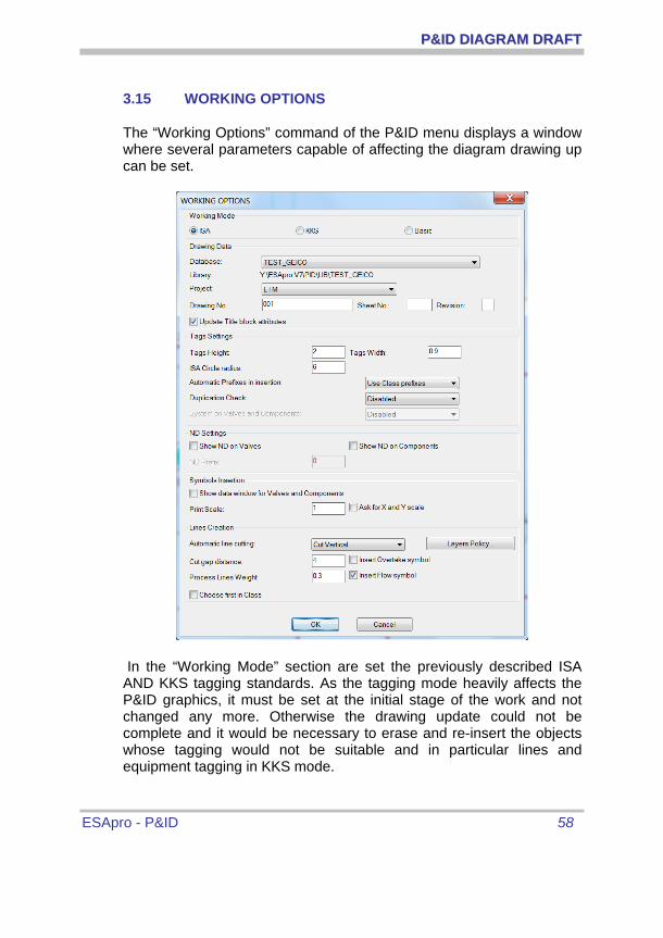
PP&&IIDD DDIIAAGGRRAAMM DDRRAAFFTT
ESApro - P&ID 58
3.15 WORKING OPTIONS
The “Working Options” command of the P&ID menu displays a window where several parameters capable of affecting the diagram drawing up can be set.
In the “Working Mode” section are set the previously described ISA AND KKS tagging standards. As the tagging mode heavily affects the P&ID graphics, it must be set at the initial stage of the work and not changed any more. Otherwise the drawing update could not be complete and it would be necessary to erase and re-insert the objects whose tagging would not be suitable and in particular lines and equipment tagging in KKS mode.

PP&&IIDD DDIIAAGGRRAAMM DDRRAAFFTT
ESApro - P&ID 59
The working database appearing on AutoCAD status line. can be set in the “Drawing Database” section
Each Database can contain different definitions of Classes, Tables and Projects. It is possible then to delimit each project within a Database whose future modifications will not affect other projects referring to different Databases. For this reason we suggest to create one Project per Database even thought more projects are allowed. The current database is stored into the drawing and is displayed at its re-opening. The database of an existing P&ID diagram can be changed. But it could necessitate the update of the lines when Classes and the symbol libraries are differing. In case of conflict the program will provide the necessary information. The program will make the updating of the whole drawing and will report eventual conflicts with the new Piping Classes.
The drawing identifying data must be specified in order to correctly transfer the components data to the Project Database. Said data are Project Code, Drawing Number, sheet Number , optional, and Revision level that initially can be blank. Said data will be mandatorily requested when launching “Data Extraction” that performs a general drawing diagnosis and data transfer to the Project Database. We point out that the Project Code cannot be entered directly but it must be chosen from the list of the already created ones. The Project creation is made in the P&ID menu Project.
If the “Update Title Block Attributes” box is checked, Project, Drawing Number, Sheet and Revision are transferred to the title box, provided it has been customized as required by the program. We remind that said customization is not mandatory; for further information see appendix A8.
In the “Tags Setting” section it is possible to set:
o The height of the component tag.
o The widening factor of tags. The value “1” keeps the original width unchanged.
o The ISA circles radius related to the equipment and to the valves (valvola di regolazione)

PP&&IIDD DDIIAAGGRRAAMM DDRRAAFFTT
ESApro - P&ID 60
o The prefix/suffix origin by choosing among Piping Class (that provides only the prefix), Symbol Archive and free manual compilation. We remind that the so assigned tag can also take a progressive number through the automatic numbering process.
o The visualisation of the system near valves and on line components (available in the KKS tagging system only).
In the “ND Setting” section it is possible to set:
o The visualisation of the nominal diameter at the side of the lines’ valves or components and a prefix. Mind that the predefined mesurment of the ND (millimetres or inches) is established in the attachments of each pipe Class used by P&ID.
In the “Symbol Insert” section:
o The visualisation of the ND near valves and on line components. We remind that the measure unit for ND is set in the P&ID Menu when the Project which the drawing belongs to is defined.
o For components or valves, the visualisation of the data window soon after the object has been inserted. The reason for that is the prompt tag compilation in case the user adopts the manual insertion
o The real time control of the possible duplication of tags entered in the current drawing and on the Project.
In the “Components Scale” section two scale factors can be inserted:
o "Print Scale", scales all the graphic elements for particular needs (i.e. drawing of a P&ID on an existing lay-out which will be printed on a scale 1:100).
o "Ask for X/Y scale", allows the user to individually scale and possibly distort a symbol at the insertion. This option remains active and must be reset when no longer needed.

PP&&IIDD DDIIAAGGRRAAMM DDRRAAFFTT
ESApro - P&ID 61
In the “Line Creation” section the following settings are provided:
o When two lines cross each other, which of the two (horizontal, vertical) is automatically cut. Such automatism can be disabled, in such case the user has at his disposal the manual command which selects the line to cut that is the first selected one.
o The size of the gap created by cutting one of two crossing lines.
o Whether a jumper symbol must be inserted on the gap in order to connect the two parts of the cut line.
o The line physical thickness which will be visible when the line thickness visualization is enabled in AutoCAD.
o The automatic insertion of flow direction symbol on the lines.
o In case of alternatives in Piping Class, whether the program must offer the choice of the possible options or automatically choose the component displayed as first in class and therefore considered the preferential one (see “Piping Class Management” further on).
Many of the above described options once modified will automatically update the drawing in order to match the new settings.
PP&&IIDD DDIIAAGGRRAAMM DDRRAAFFTT
ESApro - P&ID 62
3.16 SIZES AND TITLE BLOCKS
This part of the program deals with the insertion of the standard size borders (A0–A4) supplied with the program and the title block containing the current drawing data. These functions are available on the P&ID menu, “Title Block” or in the notation section of the Ribbon.
The selection of a size enables the insertion of the sheet border dragged through its center. The title block insertion requires its positioning within the border. A title block completed with borders can be also used avoiding in this way the border insertion.
The user can arrange text attributes into his own title block (for that purpose see the AutoCAD manuals). If said attributes include those related to Project Code, Drawing Number, sheet number and Revision the program will automatically fill them with values taken from the “Working Options” settings. For further information on title block customization see Appendix A8.

DDAATTAABBAASSEE MMAANNAAGGEEMMEENNTT AANNDD BBIILLLLSS OOFF MMAATTEERRIIAALLSS
ESApro - P&ID 63
4 DATABASE MANAGEMENT AND BILLS OF MATERIALS
The P&ID program is equipped with an external procedure accessible through the “Specific Management” command of the P&ID pull down, through the “SP” shortcut or through the related toolbar button, or in Ribbon. This procedure manages the database tables, in particular Symbols and Projects, and allows the generation of Piping Classes and Bill of Materials. Initially a mask displays giving access to various functions. The environment is made of a series of masks and commands complying with the standards of Windows. Windows are re-sizable and can fit your own needs. The set configuration is memorized and explained in the next working session.

DDAATTAABBAASSEE MMAANNAAGGEEMMEENNTT AANNDD BBIILLLLSS OOFF MMAATTEERRIIAALLSS
ESApro - P&ID 64
4.1 SYMBOL LIBRARY MANAGEMENT
On the P&ID menu press “Components” and access to the P&ID symbols management window. It is used for consulting , modifying and deleting components. Data linked to each symbol will be used whenever a component has to be identified, in the of Piping Classes creation and in Bills of Material extraction.
Every symbol is identified by its own code as described at paragraph A.1 “Symbols Arrangement”. Codes are listed below.
Description Group Actuators 0A Valves 00 o 01 Pipes 03 Line’s components 04 o 05 Motors 06 o 07 Generators 08 o 09 Pumps/ejectors 10 o 11 Compressors 12 o 13 Exchangers 14 o 15 Vessels 16 o 17 Instruments 18 o 19 Component’s symbols 20 o 21 Instrument’s symbols 22 o 23 Equipment’s symbols 24 o 25 Equipments 26 o 27

DDAATTAABBAASSEE MMAANNAAGGEEMMEENNTT AANNDD BBIILLLLSS OOFF MMAATTEERRIIAALLSS
ESApro - P&ID 65
At the top of the window there is a pull down menu where one of the groups, where the P$ID components are subdivided, can be selected Such choice filters only those components related to the selected group. The window below shows how to correct the data of a selected symbol through a mask as in the figure. Otherwise the line chosen on the list can be directly modified: the modalities are as follows.
o The Arrows allow the user to move around the various fields and from one line to another.
o Double click or F2 allow the modification of the selected data.
Bare attention to the data entered in these modes as they are recorded at once in the symbol library and cannot be modified. Symbol and code are not modifiable as they are the result of the customization procedure as well as the component type. But it is possible to automaticaly align the direction of a component on the line if "Oriented with Flow" is checked. The check on “update all databases in the library …..” allows the modifification in all databases shared by the library. Otherwise the modification applies only to the current database. For further information about the customization of the symbol go to the

DDAATTAABBAASSEE MMAANNAAGGEEMMEENNTT AANNDD BBIILLLLSS OOFF MMAATTEERRIIAALLSS
ESApro - P&ID 66
“Customization Symbol Library” appendix. Five different languages are available for the descriptions as well as for the prefix and the suffix as they are part of the tag of the drawing: the defined description can be a progressive number applied later through manual or automatic procedures.
At the side of the symbol there is a pull down menu with an index containing all the possible graphic modification of a component, but only for valves and line components.
The Delete button removes a symbol from the list unless used in Class and Documents.
The Export command inserts the symbol list into an Excel file.

DDAATTAABBAASSEE MMAANNAAGGEEMMEENNTT AANNDD BBIILLLLSS OOFF MMAATTEERRIIAALLSS
ESApro - P&ID 67
4.2 PIPING CLASSES MANAGEMENT
The “Class” concept has already been explained in chapter 3.1.
Once in “Specific Managment” enable the Class Table with the pull down menu “Tables/Classes” or press “Class” on the upper application bar. The list of the existing Classes will be displayed on the windows.
The window up above displays the list of the existing Classes. On the left there are buttons for the creation “New”, the duplication “Copy”, the removal “Delete” , “Export” to get an hard copy of the class selected on Excell. The second down button, “Detail” leads into the environment for the component management of the selected Class. The upper button “Exit” closes the application window.
The button “Attachments” for each pipe diameter sets whether the ND will be displayed in mm or inches.

DDAATTAABBAASSEE MMAANNAAGGEEMMEENNTT AANNDD BBIILLLLSS OOFF MMAATTEERRIIAALLSS
ESApro - P&ID 68
The creation of a new class requires the definition of its characteristics as shown on the window.
By pressing OK the new Class definition is inserted on the list in colour red to state that Class is still lacking details.
Through “Copy” a new class definition is immediately generated and a copy of the highlighted one can be made with the “Copy of …” command before the original Class name. Then all the needed modifications will be performed, including the change of the default name assigned by the program. To modify the value of a data field of a Class the user must highlight it with a click and then with an other one the over-writing will be enabled.
The “Detail” button or a double click on a Class of the list brings to the window that allows the user to enter the Class components.

DDAATTAABBAASSEE MMAANNAAGGEEMMEENNTT AANNDD BBIILLLLSS OOFF MMAATTEERRIIAALLSS
ESApro - P&ID 69
On the lower left there are the usual buttons for Inserting, Modifying, Deleting and Exiting from the window. The two arrows above “Insert” and “Modify” are used for the priority management in case of alternatives in Class, as described further down.
Furthermore two areas can be recognized:
o An upper one, yellow coloured, containing the detail of the components already inserted.
o A lower one where it is possible to enter the detail of a new component or to see and possibly modify data of an existing one.
An icon above on the left represents the selected component and at its right a small pull down menu contains one of the possible representations of the object called “Visualisation style”.
An icon on the left upper part of the window displays the selected component symbol.

DDAATTAABBAASSEE MMAANNAAGGEEMMEENNTT AANNDD BBIILLLLSS OOFF MMAATTEERRIIAALLSS
ESApro - P&ID 70
The insertion of a new component can work in two ways:
o By locating the wished component through the pull down list available in the “Component” box. The list contains all the objects defined in Symbol Table even the customized ones. Every component displays its internal code, Mind that only the valves and the line components are under the Class control , therefore this list will not include instruments and equipment. Its description and its figure for an easier identification and its characteristic data. Press “Insert” a The “Visualisation style” command enables the wished representation for each size range with the same code. For instance the representation of threaded ends up to a certain ND, and then flanged representation. The internal code does not change and then the Class remains valid even when in another project the visualisation style is different.
o By highlighting a component already existing in the list. A copy of the selected component is created capable of being subsequently modified. Press “Insert” to create a new record Both the original row and the duplicated one are highlighted in red, in order to make clear that. there are more versions of the same component for the same size range. When you need to modify an existing component it is enough to highlight it, make the needed changes and then press “Modify” in order to performe the upgrade.of the line.
You can insert a component in a given class more than once with the same diameter. This configuration is called “Alternative in Class”. Let’s suppose that a ball valve for a given diameter is admitted threaded as well as socket welded. In order to enable this alternative insert twice the valve symbol, whose description in “Symbol Table” is generically “Ball Valve”, choose the same diameter range, specify two different end types, and possibly other differences such as material or part number and the “Visualisation style”.
The two rows on the list will be displayed in red in order to highlight that for the same symbol there are diameters overlapping each other. In this way it is easy to diagnose and correct a possible error. When inserting the component with an alternative in Class the user will be asked to choose one of the versions and then the command will normally terminate. On the contrary if the “Choose First in Class” box of the

DDAATTAABBAASSEE MMAANNAAGGEEMMEENNTT AANNDD BBIILLLLSS OOFF MMAATTEERRIIAALLSS
ESApro - P&ID 71
“Working Options” window is checked the components displayed first among the alternatives are inserted without any further request. The order of the alternative components in Class can be changed with the arrows above the “Insert” and “Modify” buttons. In a possible bill of materials the two versions can be recognized from the different value of the end type field. Another way for implementing this variant is to customize two distinct symbols and insert them into the table with different code and description. For further information on this subject see paragraphs 4.3 “Line Management” and “Interaction between Components and Piping Class”
Now let’s examine the characteristic data that can be linked to a component.
o In the “From ND” “To ND” boxes it can be specified the nominal diameter range in which the component data are constant. This operation saves the user a lot of time and reduces the risk of typing errors. Diameters are selected within an user customizable pull down list.
o In the “Tag Prefix” box it can be specified the prefix that will be displayed at the side of the graphic symbol on the drawing. It can be subsequently integrated with a numeric progressive. For further details see paragraph “4.6 Component Tagging” and “4.13 Working Options” also)
o In the “Standard”, “Schedule/Rating” and “Material” boxes the relevant data for the component or pipe can be entered through pull down lists whose values are stored in suitable tables as described further on. Otherwise the first fitting datum is reached by entering one or more characters. For example by entering “3” into the “Schedule/Rating” box the item “300 LB” is immediately reached.
o “Part Number” “Manufacturer” and “Model” respectively indicate part number for the linkage with the enterprise management software, manufacturer and model number of the component.
o In the “End Type” box end type codes can be entered such as “butt weld”, “socket weld”, “threaded” and “flange” end type. The first two box are provided for the two ends of straight-way and angle components, the third for the branch end type of

DDAATTAABBAASSEE MMAANNAAGGEEMMEENNTT AANNDD BBIILLLLSS OOFF MMAATTEERRIIAALLSS
ESApro - P&ID 72
three-way components and the fourth for the second branch end type of four-way components. In this case also pull down lists are available whose values are stored in suitable customizable tables as described further on.
o At last five fields called “User 1-5” are available for other items not provided in the standard Class data and the “Notes” field. . We clarify the difference between these available data and those of the components. The values contained in the Class “User 1-5” fields are automatically attached to the object at every insertion. On the contrary the object available fields “Available 1-8” can get different values accordingly with the object. For example the “User 1” Class field is used to specify the finishing and is set on “galvanized”. All the objects of that type inserted into the drawing will get the value “galvanized”. Furthermore the “Available 1” field is used to specify the colour of the same object. In this case it is possible to differentiate the object freely assigning “Red” to one of them, “Green” to another one and so on. In the “Modify” mask of the component “User 1” field “galvanized” that comes from Class will be visible but not modifiable. On the contrary the “Available 1” “Red” field of an object will be visible and modifiable at any time.
The “Delete” button removes elements from the Piping Class. Before executing this command the program asks for a confirmation .
By the way the defined Classes described as above remain available without limit for future drawings.
We remind that Classes are restricted to their own Project Database and cannot interfere with those belonging to different Project Databases.

DDAATTAABBAASSEE MMAANNAAGGEEMMEENNTT AANNDD BBIILLLLSS OOFF MMAATTEERRIIAALLSS
ESApro - P&ID 73
4.3 PROJECTS MANAGEMENT
The item “Project” of the “P&ID V7” menu provides a mask for creating, modifying, visualizing, exporting, printing and deleting Projects and related drawings. Actually drawings are not physically deleted but their definition and data related to the contained components are removed from the Database. In order to restore a drawing definition it is enough to execute the “Data Extraction” operation described further on. In the P&ID environment, in order to specify the current drawing project the user will go to the “Working Options” mask and through the suitable pull down menu he will get the list displaying all the items of the Project Table for the selection.

DDAATTAABBAASSEE MMAANNAAGGEEMMEENNTT AANNDD BBIILLLLSS OOFF MMAATTEERRIIAALLSS
ESApro - P&ID 74
This item is used for the following operations:
o Insert, creates a new Project. The mask is displayed for filling in the code and description.
The code is the code reported in the material
list when the column “Project” is required. The
description is not mandatory.
o Modify, allows the change of the Project description and units through the same mask used for “Insert”.
o Delete, removes the Project definition and the related drawings from the database. The AutoCAD files are never deleted. The deleted Project can be recalled through the “Data extraction” of each drawing.
o Links, checks the cross references among the various drawings of a multisheet P&ID. For further information see chapter “Cross References and Multisheet”.
o Export, exports the list of the Project drawings in Excel.
o "Copy", allows the copy of a selected project with a new name thus creating an alternative project with the same starting values. When necessary all the lines contained in Line manager can be copied as well. The list of the drawings is not reported. The drawings of the newly named project must be open first and then the project assigned to the Working Options.

DDAATTAABBAASSEE MMAANNAAGGEEMMEENNTT AANNDD BBIILLLLSS OOFF MMAATTEERRIIAALLSS
ESApro - P&ID 75
The window “Option” allows the user to set up a series of parameters valid for all the drawings of the project. It follows a list of the various settings
Root Valves location: defines if the location of the root valves of a connected instrument must be the instrument itself rather then the line or the equipment the instrument is built on
Ignore drawing name in Library: through this command the program ignores the name of the AutoCAD file during the storage of the drawings and it acknowledges the Project, the Drawing Number and the Revision only . Then the same drawing number from two AutoCAD files is not accountable as a duplicate. Example: in case the company standards impose to rename the AutoCAD file when the revision index changes.
Revision management: it saves the lists of previous revisions ( the option is available in the module P&ID Plus only).
Tag: it defines the line tag for the whole Project. The command “Line Tag” in the AutoCAD environment will use such composition. See paragraph 3.7 “Line Tagging” for further information about the use of the mask.

DDAATTAABBAASSEE MMAANNAAGGEEMMEENNTT AANNDD BBIILLLLSS OOFF MMAATTEERRIIAALLSS
ESApro - P&ID 76
In the “Line and Drawings” pull down menu in the “Lines” section.
Line creation mode: The lines of the project will be predefined in “Line Manager” by a supervisor or the lines will be created first in a graphic environment and then entered into “Line Manager”
Lines numbering criteria: determines if the line tag must contain, beside the usual Unit/System+Number also the Fluid. In this case it is allowed to assign the same line Number to lines with different Fluids. This procedure though might affect P&ID Piping and Sketch and cannot be modified if some drawings have already been extracted from the Project.
Lines numbering : the Line Number of the creation mask can be assigned in automatic as progressive or inserted manually
In the “Drawing” section.
“Disable drawing update at the opening “ inhibits the automatic updating of a drawing at its opening caused by a data modification in “Line Manager”.

DDAATTAABBAASSEE MMAANNAAGGEEMMEENNTT AANNDD BBIILLLLSS OOFF MMAATTEERRIIAALLSS
ESApro - P&ID 77
Saving procedures : determines the saving procedure of the drawings of a Project for each ESApro application so to update, when necessary, all the drawings of a Project.

DDAATTAABBAASSEE MMAANNAAGGEEMMEENNTT AANNDD BBIILLLLSS OOFF MMAATTEERRIIAALLSS
ESApro - P&ID 78
4.4 BILL OF MATERIALS
Once completed the P&ID with graphics and data, bill of materials can be extracted.
At first the project database has to be updated with new drawing data with the “Data Extraction” command. This operation loads all data of the drawing components into the Database with the project and drawing number previously specified through “Working Options”. During the data extraction process a full drawing check is performed and eventual problems are reported. The drawing check can also be carried out by the “Drawing Check” command. Its options allow the user to inspect the correctness of lines and components on the whole drawing or on a selected subset.
Some objects can be arranged so that they will not become a part of the bill of material. For example the parts of existing lines or the parts provided by a third party. “Xclude from bill of material” command allows the selction of such objects. Also another option is available to re-install objects previously selected. The excluded objects are positioned upon the “ESApro-xclude” layer in light blue colour and dashed line so to easily trace them. Such characteristics can be changed at will. Press once the “Line Grouping” command to select a whole line and its branches.
Then bills of materials, customized by procedures described at paragraph 4.5 “Management of Bill of Materials Models”, can be extracted from the Database. Bills of materials can be put on the drawing under the form of a table or sent to the monitor or system printer or exported as an ASCII, XLS; Access file. Let’s look in detail into the generation procedure.
The “Create material list” command launched from the “P&ID” Menu requires the choice of a BOM model and displays a tab on the drawing. Theese tabs are automatically added during the “Data Exctraction “ procedure, described further on. Then it generates a table on the drawing. In order to make the choice of models easier they have been divided in homogeneous groups. Therefore you have to choose

DDAATTAABBAASSEE MMAANNAAGGEEMMEENNTT AANNDD BBIILLLLSS OOFF MMAATTEERRIIAALLSS
ESApro - P&ID 79
a group first. In this case the list is limited to the current drawing. The tab is then generated and remains hooked to the cursor to be definetly positioned.
The graphic entities constituting the table are put on layers with the prefix “tab_”. In such a way different colours can be assigned to frames, titles, descriptions, symbols in order to adhere to their own printing standards.
A template is provided to automatically generate a legend with the only description next to the column of symbols. It provides two versions that cover the handling of instruments. In one case, the generic symbol is listed with its description, eg.: "Local ISA Instrument". In the other are listed separately all kinds of Instruments made by the same symbol, eg.: "Pressure indicator" , "Temperature indicator". In the example it can be noticed also the use of two contemporary languages for descriptions.
In order to direct the BOM to other destinations it is required to generate them with the P&ID Menu procedure activated by the “P&ID “Specific Management” pull down or the shortcut “SP” or the provided toolbar button. Then press the “BOM” button. The dialogue window is shown in figure with the Project list on the left and the related drawings on the right. It is now possible to choose both the project and the group

DDAATTAABBAASSEE MMAANNAAGGEEMMEENNTT AANNDD BBIILLLLSS OOFF MMAATTEERRIIAALLSS
ESApro - P&ID 80
of drawings which the bills of materials have to be extracted from. In the upper part, once selected a group, a pull down list shows the same models previously used when generating the table on the drawing. The model fully defines the content and the appearance of the Bill of Materials. In the lower part of the mask the output for the Bill of Materials can be selected choosing on the screen display or ASCII file or EXCEL worksheet or printer.

DDAATTAABBAASSEE MMAANNAAGGEEMMEENNTT AANNDD BBIILLLLSS OOFF MMAATTEERRIIAALLSS
ESApro - P&ID 81
4.5 MANAGEMENT OF BILL OF MATERIALS MODELS
The Bill of Materials Models are user-defined collection of information that specify the appearance and the content of the Bills of Materials. Once created they are stored into the database and remain available for future use in any P&ID Project.
Select “List Models” in the “Projects” pull down menu and the environment for managing these structures will be available.
In the upper part of the mask a pull down list shows the BOM types organized in homogeneous groups of components. Down below there is the list of the models in yellow and in the lower part the detail of the selected model in blue. On the left there are buttons for the management of the two environments. Press “Insert” and a mask appears in the upper part of the window where necessary data for a new model creation can be entered. The same mask appears when modifications to a model are required. The description value recognizes the "Model" within the list while “Title” is the heading of the out and out table. In the pull down list “Language” one or two of the five languages provided on the table for the components description can be chosen. At last by pressing the question mark beside the “Groups” box a list appears which contains all the groups of suitable components for the selected model type. The user can select one or more of said groups in order to filter the bill of materials. On the example at the side only the Pumps/Ejectors group has been enclosed in an equipment list.

DDAATTAABBAASSEE MMAANNAAGGEEMMEENNTT AANNDD BBIILLLLSS OOFF MMAATTEERRIIAALLSS
ESApro - P&ID 82
Modifications to an existing model can also be directly carried out in the yellow list using the same rules previously described for the symbol table. The “Delete” button removes the selected model. “Copy” creates a new model equal to the selected one which will subsequently be possible to adjust for the new requirements. In the lower part of the mask the model detail is defined. The aim is to specify which data has to appear on the BOM and their order. “Insert” offers a mask for adding a new column to the model. In the “Field” pull down list the required field is selected. In the “Heading” box the column title is entered. In the filter box one or more values can be entered, delimited by commas, in order to restrict the BOM to the components with one of those values in the selected field. For example for the field “line number” all the components belonging to line “0132” could be filtered. In the field “Exclude” a filter working in the opposite way can be set, so that the BOM would be restricted to all components which have in the field a value different from those specified.
The two arrows at the side of the field list are used for setting up the order of appearance of columns on the BOM. Once selected a row can slip up or down until it reaches for the desired position.
We point out that the BOM sorting-out starts from the first column onwards. Therefore if ND column is in first position the BOM will be sorted out by increasing ND and, if Class column is in second position, at equal ND, the BOM will be sorted out by class and so on. Sometimes it can be useful to set a data field in the BOM sorting out or in a filter but without displaying it. To this purpose uncheck the “Visualization” box.

DDAATTAABBAASSEE MMAANNAAGGEEMMEENNTT AANNDD BBIILLLLSS OOFF MMAATTEERRIIAALLSS
ESApro - P&ID 83
An interesting example is represented by the “Component Code” field. Once selected the question mark at the side of Filter, the list of the components existing inside the table is shown in order to make the choice easier. The Component Code can be useful either for building a filter or for sorting-out the BOM by homogeneous groups as well. However it will not be displayed as not useful for the documents of the project
If the “Quantity” field appears on a list keep in mind the concept used for calculations making. Two objects are considered equal when all data fields requested in the list have the same value. In this case the quantities’ numeric field is increased. Therefore the quantity depends on the columns existing on the list. For example valves will be summarized but shared line by line. On the contrary if the line list field is removed from the model all the equal valves will be grouped even if laying on different lines.
In case of modification a mask is offered similar to that for the insertion. Otherwise the user can directly work on the list with the already described conventions. “Delete” removes the line relevant to the selected field.
The Nozzle List is shown in the figure. It is not customizable and can be exported in ASCII, EXCEL file format.

DDAATTAABBAASSEE MMAANNAAGGEEMMEENNTT AANNDD BBIILLLLSS OOFF MMAATTEERRIIAALLSS
ESApro - P&ID 84
4.6 FIND DUPLICATE TAGS
The “Find Duplicate Tags” command of the P&ID Menu, pulls down “Projects” to check that no duplicated tags exist on all the Project drawings.
Once selected a project a list of the duplicated tags and of the drawings related will appear on the mask as shown below. Said list can be displayed or redirected to an Excel file or to an Access table.
The program does not consider duplicated blank tags or those containing the standard Class or Table prefix still missing of the progressive number.

DDAATTAABBAASSEE MMAANNAAGGEEMMEENNTT AANNDD BBIILLLLSS OOFF MMAATTEERRIIAALLSS
ESApro - P&ID 85
4.7 NOMINAL DIAMETER TABLE
New values can be added to the nominal diameter table through the procedure “Files/Diameters”. “Insert” and “Modify” offer the same mask where it is possible to add or modify a diameter in the double representation of meters or inches. The denomination in inches is optional. If needed a ND can be removed with the “Delete” button.
4.8 INSTRUMENT TYPE LIBRARY
Instruments are generically described in the symbol library. For instance a pressure gauge is described as “Instrument connected to the line” . But only after the user has inserted it and characterized it with the instrument type “PI” the pressure gauge will be acknowledge by the program. Therefore the generical description cannot be used in an instrument list. At its place will be found instead the description entered in “Instrument Types” library corresponding to the selected code.

DDAATTAABBAASSEE MMAANNAAGGEEMMEENNTT AANNDD BBIILLLLSS OOFF MMAATTEERRIIAALLSS
ESApro - P&ID 86
4.9 CUSTOM LIBRARIES
In order to define unexpected feature all components which can be inserted in a P&ID diagram have 8 data fields, generically defined as Custom 1-8. In this library it is possible to customize the Custom 1-8 prompts, so that they fully acknowledge the significance the user want them to have. The customization can be applied to each category of predefined objects in EASpro P&ID. Moreover in Equipment, where are represented the generic those which cannot be inserted in pumps, exchangers, compressors, etc. It is possible to customize the available fields of each equipment. Insert the equipment in the lower part of the mask and proceed to fill in the descriptions.

DDAATTAABBAASSEE MMAANNAAGGEEMMEENNTT AANNDD BBIILLLLSS OOFF MMAATTEERRIIAALLSS
ESApro - P&ID 87
4.10 INSULATING CLASS LIBRARY
It is a library where the user can define for each Insulating Class its code, material, a mnemonic description, and, according to their diameters, the related thicknesses as well. Such data are used during the creation of a line. Once selected an Insulating Class, the materials, and the previously defined thicknesses can be downloaded into the line’s mask.

DDAATTAABBAASSEE MMAANNAAGGEEMMEENNTT AANNDD BBIILLLLSS OOFF MMAATTEERRIIAALLSS
ESApro - P&ID 88
4.11 OTHER TABLES
In the pull down menu “File” other items appear: “Materials”, “Standards”, “Ratings”, “End Types”. They are additional tables where a set of pre-defined values can be stored. Said predefined values are used in the pull down menus when required. Vantages are the following:
o No manual input is required thus improving efficiency and minimizing possible typing errors.
o When entered a set of characters the first datum beginning with that set is selected. For example if the digit “3” is typed in the “Rating” field, the system immediately offers “300 LB”.
o Entered data are standardized. It will prevent from meeting the same rating once written “300 LB”, or “300#” and so on. This makes the operation of inquiring or filtering into the database all inclusive and reliable.
The maintenance and feeding operations of these tables are very easy: Insertion of new data or deletion are provided. Records in the tables appear in alphabetical order.

DDAATTAABBAASSEE MMAANNAAGGEEMMEENNTT AANNDD BBIILLLLSS OOFF MMAATTEERRIIAALLSS
ESApro - P&ID 89
4.12 UTILITIES
In the “Utilities” pull down Menu some procedures for aiding the P&ID environment setting are available.
Database Management, allows the maintenance of the ESApro P&ID working Databases
ESApro P&ID can handle more databases. Each one of those , once created can contain Materials, Classes and Projects independently from those of another Project Database. The main purpose for that is to isolate each Project into one Database, even if more Projects can be contained in one database. This is how the materials and the classes of the project are modifiable without affecting other projects.
From the 2009 edition of ESApro onward the database is SQL Server. Such choice been made in order to guarantee the compatibility with the 64 bit platform and to increase the level of security in he net environment.

DDAATTAABBAASSEE MMAANNAAGGEEMMEENNTT AANNDD BBIILLLLSS OOFF MMAATTEERRIIAALLSS
ESApro - P&ID 90
All existing Databases are listed on the mask. All the libraries, Classes and Projects can be independently customized in each Database. Each database can be assigned a different symbol library.
Once selected a Database, at first only “ESAin” exists, and pressing “Open” it enables the setting up of the current database in the “Specifics Management” environment. The name is shown on the application tool bar up above. If other operators are connected they will be able to keep working on their current database. Mind that the Database set in a AutoCAD drawing through “Working Option” is not affected by such a choice.
Select a Database and press “Copy” to create a new copy of the Project Database. The program automatically checks out that no other users are interfering with the project, but if so sends an error message. Then a mask displays to name the project ( no empty spaces or special digits are allowed) .
It is also visualized the name of the file containing the symbol library of the original Database. Its name can be maintained or a new one can be chosen. In the first case the new Database will share the library with the original one otherwise the original library is duplicated in a new folder so that the

DDAATTAABBAASSEE MMAANNAAGGEEMMEENNTT AANNDD BBIILLLLSS OOFF MMAATTEERRIIAALLSS
ESApro - P&ID 91
modification will not affect the original one. In any case initially the library is the same as the original, otherwise Classes might end up beeing uncorrect. Beside it is possible to cancel all data of the original Database in order to create an empty new one. This can be useful when it does not exist a Database similar to those required by the new Project. In this case it is possible to import the data from other databases through the procedure “Import/Export data from-to Databases“ which will be described further on. In any case the Classes and the libraries imported from the original database, can all be independently modified. Once ended the procedure the Database is set as the current database.
The program will create two file for each new Database created by the operator, which the SQL server relies on. By convention the name of the file is the following one: NewProject.MDF, NewProject_LOG.LDF, where NewProject is the name of the Database. Such files, when used by the database, cannot be treated by the operating system and therefore cannot be copied or loaded into another environment. All the management procedures of the files must be carried on through the commands provided by the application.
Press “Import” to insert a new Database. It is imported from the folder the operator indicates. The name of the database is the same as the MDF file’s name without the extension. The program checks there are not other databases with the same name.
Press “Export” to create a new copy of the Database and move it in other working environment. The choice of the folder where to process the database is up to the user. It is also possible to rename the database. The program checks no other operators are working at the same time at the same database.
Press “Delete” to permanently remove a database either from the procedure and the system disk. A window will display asking to confirm the procedure. While proceeding the program verifies that no other operators are working at the database. The “Delete” procedure is necessary when the project is completed or just before importing a Database with the same name in order to work on an updated version.
Press “Back-up” in order to export at the same time all Databases of the procedure to create one copy for safety reasons. The operator will

DDAATTAABBAASSEE MMAANNAAGGEEMMEENNTT AANNDD BBIILLLLSS OOFF MMAATTEERRIIAALLSS
ESApro - P&ID 92
choose the export folder. At the same time the program denies the access to any other operators at the moment of the back-up.
After many updating procedures it is advisable to use the “Compact“ command in order to reduce the size of the Database.
One Database is available at least, when autoCAD with ESApro P&ID is open. When none open Database is required in order to perform the procedures just described, ESApro P&ID must be disabled. To this purpose the “Database Managment” program icon is on the desktop of of Windows(ESApro GDB V7) so to be enabled outside ESApro P&ID. Its working procedure is exactly the same as that used in “Utility” , except for the “Update” command. This last option can update obsolete imported databases without affecting the data contained in the Datbase libraries.
Password Change, enters or replaces the password for accessing to functions of modification and deletion on the Database and Class management. If the password frame remains blank no restriction to the procedure use will be effective.
Class acquisition from the Piping Environment, allows to import a Class already defined in ESApro 3D Piping environment. On the mask the user can choose one of the Project Databases. In the lower part Classes belonging to the selected Database will appear. Once selected a Class by pressing “Import” it will be imported into the current Database of the P&ID. The correspondence between Piping and P&ID objects is set in the Piping 3D component table. In case of modification the Piping Class will need to be re-imported into the P&ID environment in order to use the updated version in this environment as well. Any modification made to the imported Class within the P&ID environment does not update the Piping 3D Class.

DDAATTAABBAASSEE MMAANNAAGGEEMMEENNTT AANNDD BBIILLLLSS OOFF MMAATTEERRIIAALLSS
ESApro - P&ID 93
Import / Export data between databases, allows the exchange of data between one database and an other. It is required the name of the secondary database, that’s to say the library from or to the data are exported or imported.
Once defined the secondary library, its data display on the lower part of the mask ( pale blue background), while the components of the secondary library at the moment used by ESApro, display above.
The components types which can be handled in the up-dating process are:
o Tabs ( only ESApro 3D Piping, ISO )
o Classes
o Supports ( only ESApro 3D Piping )
o Equipment ( only ESApro 3D Piping , ISO )

DDAATTAABBAASSEE MMAANNAAGGEEMMEENNTT AANNDD BBIILLLLSS OOFF MMAATTEERRIIAALLSS
ESApro - P&ID 94
o BOM templates
o Insulation Classes
o Symbols
o Typologies ( only ESApro 3D Piping , ISO )
Use the related buttons on the upper part of the mask to enable the required data.
Export, in order to export data they must be first selected in the primary Database (upper part of the window) then press the low “Export” button.
Import, in order to import data they must be first selected in the secondary Database (lower part of the window) then press the low “Import” button.
In case data existing in the primary or secondary database need to be overwritten check the “Overwrite Existing Data” box; otherwise the already existing components (with the same identifier) will not be imported or exported.
In order to perform the import/export of whole data simply use the red arrow button in the upper part of the toolbar.
Also in this case the overwriting checkbox controls whether the already existing components has to be imported or not.

CCUUSSTTOOMMIIZZAATTIIOONN PPRROOCCEEDDUURREESS
ESApro - P&ID 95
A. CUSTOMIZATION PROCEDURES
In the following paragraphs we will describe the procedures for adding, modifying or deleting the symbology used by the P&ID program.
We will also explain how to customize the title block so to enable the automatic loading of the anagraphic data of the drawing.
A.1 SYMBOL ARRANGEMENT
In order to insert a new object into the P&ID environment a code needs to be assigned to it. before describing the customization procedures the Symbol Table arrangement will be then explained. The library elements have been divided into groups. Each element is identified by a four digit code, the first two standing for the group and the last two being a progressive number from 0 to 99. With few exceptions, each element type has two group codes. In such way for every group up to two hundreds components can be defined. The following table states the component group identifier.
Description Group Actuators 0A Valves 00 o 01 Pipes 03 Line’s components 04 o 05 Motors 06 o 07 Generators 08 o 09 Pumps/ejectors 10 o 11 Compressors 12 o 13 Exchangers 14 o 15 Vessels 16 o 17 Instruments 18 o 19 Component’s symbols 20 o 21 Intrument’s symbols 22 o 23 Equipment’s symbols 24 o 25 Equipments 26 o 27
CCUUSSTTOOMMIIZZAATTIIOONN PPRROOCCEEDDUURREESS
ESApro - P&ID 96
The combined code Group + Progressive is the element name and is shown on the Symbol Table. Therefore 0032 identifies a valve as its group is 00 or 01 and progressive number from 00 to 99. One only explicit description on the table corresponds to this criteria (example: Gate).
Actuators are different; their group code is 0A. They are never inserted alone but always combined with a valve. In this case the name of the combined object that is created is the sum of valve and actuator names. For example 00020A01 represents valve 0002 (ex. Sphere) driven by actuator 0A01 (ex. Mechanical Release).

CCUUSSTTOOMMIIZZAATTIIOONN PPRROOCCEEDDUURREESS
ESApro - P&ID 97
A.2 GRAPHIC SYMBOL DRAWING
In order to generate a component symbol, the graphic part must be drawn as normally in AutoCAD. At this point launch the procedure of customization in the Instrument section, or in Ribbon or in the Toolbar. A mask displays with all the various customize, add, modify, and delete options.

CCUUSSTTOOMMIIZZAATTIIOONN PPRROOCCEEDDUURREESS
ESApro - P&ID 98
The “Create new P&ID symbol” option displays the window where the following fields are listed
• Select a component type: and on the left are displayed the first two ciphres of the code assigned to each group.
• New code: displays the first available code of the component required. The “Symbol library” button enables the list of the existing components as a reference thus allowing the user to choose a free number code.
• Component type: the user has to indicate the number of.ways. of the component, when suitable, which can be 2,3,4 or angled Aside , for the 2 ways only, when it is required to invert the direction at the insertion The choice applied to the instruments is between connected, non connected or in line. The equipment will require the positioning of the tag
• Description: describes in five different languages the new object and the note will be visualized in the material lists. The first two languages are respectively Italian and English.
• Prefix Suffix: represent two alphanumeric codes which, togheter with the progressive number inserted on the drawng, will create the component tag. Another very useful.possibility for the creation of the tag is available in Pipe Class. Compose in this library a static tag attached to the component, in Classes a tag that can be different for each Class and also for a different ND.
Digit OK to visualize a mask where the user is required to:
• Select the graphic entities corresponding to the required component.
• Point at its insertion.
• Indicate the two ends left and right allowing the line cutting for linear components.
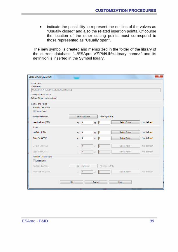
CCUUSSTTOOMMIIZZAATTIIOONN PPRROOCCEEDDUURREESS
ESApro - P&ID 99
• indicate the possibility to represent the entities of the valves as “Usually closed” and also the related insertion points. Of course the location of the other cutting points must correspond to those represented as “Usually open”.
The new symbol is created and memorized in the folder of the library of the current database “...\ESApro V7\Pid\Lib\<Library name>” and its definition is inserted in the Symbol library.

CCUUSSTTOOMMIIZZAATTIIOONN PPRROOCCEEDDUURREESS
ESApro - P&ID 100
The “Help” button displays a window clarifying which are the points required in order to match the types of objects to customize.
The customization mask allows to add a new representation style to an existing component, for valves and line components. A new style satisfies the two most common requirements. To have , in the first case , a different look , for different diameters, of threaded objects, socket welds, flanged, or butt weld. Second case to obtain a different look when it is required by the Project. At the moment of the selection of the pipe Classes it is possible to select the component style between the available ones. Once selected the component the procedure is the same as for creation, that is to say style with index zero.
The same procedure is applied to the modification of an existing style, once chosen of course the component code and the style.
“Delete component Style” erases an unwanted style.
A symbol in the library can be updated through the related AutoCAD file. Geometrical solutions can be applied unless they interfere with the references points.
The Instrument type , ND and Tag can be repositioned.

CCUUSSTTOOMMIIZZAATTIIOONN PPRROOCCEEDDUURREESS
ESApro - P&ID 101
A.3 TITLE BLOCK CUSTOMIZATION
In general any user title block can be used. The customization purpose is just to synchronize the data “Project”, “Drawing Number”, "Sheet Number" and “Revision” entered in the “Working Options” window with those existing in the user title block.
Actually the title block is a simple AutoCAD block with a number of text attributes such as Title, Scale, Company, Draftsman etc. Usually there are also the basic identifying data, Project, Drawing Number, Sheet Number and Revision that ESApro P&ID uses for filing the drawings and that are filled in through the “Working Options” window. If these data exist as title block attributes also, the program automatically updates them so saving a double data entering. To this purpose attributes tags must have specific tags as described below:
Attribute Tag Description COMM Project Code NDIS Drawing Number REVISIONE Revision Number NFOG Sheet Number
Therefore the steps for the customization are the following:
- Draw the title block and attach your own text attributes.
- Attach also Project Code, Drawing Number, Sheet Number and Revision Number attributes according to the above table.
- Save the new title block
The title block is ready. Project Code, Drawing Number and Revision Number entered in the “Working Options” will automatically be transferred into the title block.