Embed Size (px)
Citation preview

SPACEWIRE-RT D6.1 – Draft SpaceWire-RT Standard Grant Agreement: 263148 Dissemination level: Public (PU)
Page 1 of 157 Version: 1.00 Status: Released © SPACEWIRE-RT Consortium 2013
D6.1 Draft SpaceWire-RT Standard
Lead Beneficiary: University of Dundee Author(s): Steve Parkes, UNIVDUN Work Package: WP6 Task: Task 1 Version: 1.00 Last modified: 27/05/2013 Status: Released Approved by: S.M. Parkes Date: 24th May 2013
Disclaimer: The material contained in this document is provided for information purposes only. No warranty is given in relation to use that may be made of it and neither the copyright owners or the European Commission accept any liability for loss or damage to a third party arising from such use.
Copyright Notice:
Copyright SPACEWIRE-RT Consortium 2013. All rights reserved.

SpaceFibre Specification Draft F1: 7th May 2013
SpaceFibre Specification Draft F1
LIKELY TO CHANGE!
Authors: Steve Parkes Albert Ferrer Alberto Gonzalez Chris McClements

SpaceFibre Specification Draft F1: 7th May 2013
3
Copyright © 2013 University of Dundee
This page is blank intentionally.

SpaceFibre Specification Draft F1: 7th May 2013
4

SpaceFibre Specification Draft F1: 7th May 2013
5
Change log
Draft Authors Details
Draft A
31st Oct 2007
S.M. Parkes
C. McClements
Initial version.
Draft B
22nd Sept 2011
S.M. Parkes Extensive revisions and re drafted in ECSS format.
Draft C
8th Dec 2011
S.M. Parkes
Albert Ferrer
Technical corrections following prototyping and other minor revisions.
Draft D
29th Feb 2012
S.M. Parkes
Albert Ferrer
Alberto Gonzalez
Technical corrections and clarifications following review.
Draft E1
28th Sept 2012
S.M. Parkes
Albert Ferrer
Alberto Gonzalez
Retry layer completed.
Lane initialisation state diagram simplified.
Data word identification state diagram simplified.
Control symbols changed to improve robustness.
Service interfaces improved.
Quality of service specification improved.
Management parameters added.
Electrical connectors and cable added to physical layer.
Other corrections and clarifications throughout the document.
Draft F1
7th May 2013
S.M. Parkes
Albert Ferrer
Alberto Gonzalez
Various updates following simulation of the SpaceFibre standard by SUAI and comments from NEC, MELCO and JAXA.
Restructuring of the protocol stack.
Additional specification information added throughout the document.

SpaceFibre Specification Draft F1: 7th May 2013
6
Table of contents
Change log ................................................................................................................. 5
1 Scope ..................................................................................................................... 11
2 Normative references ........................................................................................... 12
3 Terms, definitions and abbreviated terms .......................................................... 13
3.1 Terms defined in other standards............................................................................ 13
3.2 Terms specific to the present standard ................................................................... 13
3.3 Abbreviated terms ................................................................................................... 18
3.4 Conventions ............................................................................................................ 19
4 Principles .............................................................................................................. 20
4.1 SpaceFibre purpose ............................................................................................... 20
4.2 Guide to clause 5 .................................................................................................... 20
4.3 SpaceFibre overview .............................................................................................. 22
5 Requirements ........................................................................................................ 25
5.1 Overview................................................................................................................. 25
5.2 SpaceFibre service interface specifications ............................................................ 25
5.2.1 SpaceFibre protocol stack ......................................................................... 25
5.2.2 Network layer service interface ................................................................. 26
5.2.3 Quality layer service interface ................................................................... 29
5.2.4 Multi-lane layer service interface ............................................................... 30
5.2.5 Lane layer service interface....................................................................... 32
5.2.6 Physical layer service interfaces ............................................................... 33
5.2.7 Management layer service interface .......................................................... 35
5.3 Formats .................................................................................................................. 37
5.3.1 Control word format ................................................................................... 37
5.3.2 SpaceFibre Characters ............................................................................. 53
5.3.3 Frame Format ........................................................................................... 56
5.3.4 SpaceFibre packet format ......................................................................... 59
5.3.5 Control word and frame precedence ......................................................... 60
SpaceFibre Specification Draft F1: 7th May 2013
7
5.3.6 K-code summary ....................................................................................... 61
5.3.7 Control word symbol summary .................................................................. 62
5.4 Network layer .......................................................................................................... 62
5.4.1 Network structure ...................................................................................... 62
5.4.2 Packet switching scheme .......................................................................... 63
5.4.3 Messages broadcasting ............................................................................ 66
5.4.4 Network management ............................................................................... 66
5.5 Quality layer ............................................................................................................ 66
5.5.1 Virtual channels......................................................................................... 66
5.5.2 Broadcast messages ................................................................................. 77
5.5.3 Frames ...................................................................................................... 78
5.5.4 Retry ......................................................................................................... 80
5.6 Multi-lane layer ..................................................................................................... 100
5.6.1 Multi-lane control ..................................................................................... 100
5.6.2 Multi-lane synchronisation ....................................................................... 101
5.6.3 Multi-lane distribution .............................................................................. 102
5.6.4 Multi-lane concentration .......................................................................... 102
5.6.5 Multi-lane selection ................................................................................. 103
5.7 Lane layer ............................................................................................................. 103
5.7.1 Lane initialisation and standby management ........................................... 103
5.7.2 Data rate adjustment ............................................................................... 119
5.7.3 Idle words................................................................................................ 119
5.7.4 Parallel loopback ..................................................................................... 120
5.7.5 8B/10B encode/decode ........................................................................... 120
5.7.6 Symbol synchronisation .......................................................................... 123
5.7.7 Word Synchronisation ............................................................................. 127
5.8 Physical layer ....................................................................................................... 127
5.8.2 Serialisation ............................................................................................ 128
5.8.3 Electrical SpaceFibre medium ................................................................. 129
5.8.4 Fibre optic driver and receiver ................................................................. 134
5.9 Management layer ................................................................................................ 134
5.9.2 Configuration parameters ........................................................................ 134
5.9.3 Status parameters ................................................................................... 136
5.9.4 Reset ...................................................................................................... 138
5.10 SpaceFibre conformance ...................................................................................... 140
5.10.1 Overview ................................................................................................. 140
5.10.2 Partial implementations ........................................................................... 140

SpaceFibre Specification Draft F1: 7th May 2013
8
Annex A (informative) Serial Data Link Concepts .............................................. 141
A.1 Data Scrambling ................................................................................................... 141
A.2 8B/10B Encoding and Decoding ........................................................................... 142
A.2.1 8B/10B Encoding .................................................................................... 143
A.2.2 8B/10B Decoding .................................................................................... 145
A.2.3 Disparity .................................................................................................. 148
A.3 Serialisation and De-Serialisation ......................................................................... 150
A.4 Receive Clock Recovery ....................................................................................... 150
A.5 Symbol Synchronisation ....................................................................................... 151
A.6 Receive Elastic Buffer ........................................................................................... 153
Annex B (informative) Example of SpaceFibre CRC implementation ............... 156
B.1 Overview............................................................................................................... 156
B.2 VHDL implementation of SpaceFibre CRC ........................................................... 156
Bibliography ........................................................................................................... 157
Figures Figure 4-1 Overview of SpaceFibre CODEC ........................................................................ 22
Figure 5-1 Overview of SpaceFibre CODEC ........................................................................ 26
Figure 5-2 Fills in a virtual channel buffer ............................................................................. 55
Figure 5-3 Data Frame Format ............................................................................................. 56
Figure 5-4 Idle Frame Format ............................................................................................... 57
Figure 5-5 Broadcast Frame Format ..................................................................................... 58
Figure 5-6 Scrambler / De-Scrambler ................................................................................... 78
Figure 5-7 Data Word Identification State Machine ............................................................... 81
Figure 5-8 Receive Error State Machine ............................................................................... 97
Figure 5-9 Lane Initialisation State Machine ....................................................................... 104
Figure 5-10 Receive Synchronisation State Machine.......................................................... 124
Figure 5-11 Transmitter Signals ......................................................................................... 129
Figure 5-12 Transmitter test circuit ..................................................................................... 130
Figure 5-13 Transmitter eye pattern mask .......................................................................... 130
Figure 5-14: Receiver eye pattern mask ............................................................................. 131
Figure 5-15 SpaceFibre EGSE cable assembly .................................................................. 132
Figure 5-16 SpaceFibre flight cable assembly .................................................................... 133
Figure 5-17 SpaceFibre EGSE to flight adaptor cable assembly......................................... 133
Figure 5-18 SpaceFibre flight connector saver ................................................................... 134

SpaceFibre Specification Draft F1: 7th May 2013
9
Tables Table 5-1 Transmit SerDes Interface (10-bit) ........................................................................ 34
Table 5-2 Transmit SerDes Interface (20-bit) ........................................................................ 34
Table 5-3 Transmit SerDes Interface (40-bit) ........................................................................ 34
Table 5-4 Receive SerDes Interface (10-bit) ......................................................................... 34
Table 5-5 Receive SerDes Interface (20-bit) ......................................................................... 34
Table 5-6 Receive SerDes Interface (40-bit) ......................................................................... 35
Table 5-7: Lane control words .............................................................................................. 38
Table 5-8: Lane Synchronisation Control words ................................................................... 43
Table 5-9: Retry Control word ............................................................................................... 44
Table 5-10: Data Framing Control words .............................................................................. 48
Table 5-11: Flow control word .............................................................................................. 52
Table 5-12: Receive error indication control word ................................................................. 53
Table 5-13: SpaceFibre N-Char Symbols ............................................................................. 54
Table 5-14: Fill control word Symbol ..................................................................................... 55
Table 5-15: Meaning of K-codes ........................................................................................... 61
Table 5-16: Meaning of control word symbols....................................................................... 62
Table 5-17: Routing switch addresses .................................................................................. 63
Table 5-18 Precedence for Different Qualities of Service ..................................................... 72
Table 5-19 RxNothing State ................................................................................................. 82
Table 5-20 RxDataFrame State ............................................................................................ 83
Table 5-21 RxBroadcastFrame State ................................................................................... 84
Table 5-22 RxBroadcast&DataFrame State .......................................................................... 85
Table 5-23 RxIdleFrame State .............................................................................................. 86
Table 5-24 Valid Positive State ............................................................................................. 98
Table 5-25 Valid Negative State ........................................................................................... 98
Table 5-26 Error Positive State ............................................................................................. 99
Table 5-27 Error Negative State ......................................................................................... 100
Table 5-28 ColdReset State ............................................................................................... 105
Table 5-29 ClearLine State ................................................................................................. 106
Table 5-30 Disabled State .................................................................................................. 108
Table 5-31 Wait State ......................................................................................................... 109
Table 5-32 Started State .................................................................................................... 110
Table 5-33 InvertRxPolarity State ....................................................................................... 111
Table 5-34 Connecting State .............................................................................................. 112
Table 5-35 Connected State ............................................................................................... 114
Table 5-36 Active State ...................................................................................................... 116

SpaceFibre Specification Draft F1: 7th May 2013
10
Table 5-37 PrepareStandby State ...................................................................................... 117
Table 5-38 LossOfSignal State ........................................................................................... 118
Table 5-39 5B/6B Encoding ................................................................................................ 122
Table 5-40 3B/4B Encoding ................................................................................................ 123
Table 5-41 LostSync State ................................................................................................. 125
Table 5-42 CheckSync State .............................................................................................. 126
Table 5-43 Ready State ...................................................................................................... 126
Table 5-44 Transmit Serial Interface ................................................................................... 128
Table 5-45 Receiver Serial Interface .................................................................................. 128
Table 5-46 SpaceFibre Interface Configuration Parameters ............................................... 135
Table 5-47 SpaceFibre Interface Status Parameters .......................................................... 137
Table 5-48 Effects of Cold Reset and Warm Reset ............................................................ 139

SpaceFibre Specification Draft F1: 7th May 2013
11
1 Scope
SpaceFibre is a very high-speed serial link designed specifically for use onboard spacecraft. SpaceFibre is able to operate over fibre-optic and electrical cable and support data rates of 2 Gbit/s in the near future and up to 5 Gbit/s long-term. It aims to complement the capabilities of the widely used SpaceWire onboard networking standard: improving the data rate by a factor of 10, reducing the cable mass and providing galvanic isolation. Multi-laning improves the data-rate further to well over 20 Gbits/s.
SpaceFibre provides a coherent quality of service mechanism able to support best effort, bandwidth reserved, scheduled and priority based qualities of service. It substantially improves the fault detection, isolation and recovery (FDIR) capability compared to SpaceWire.
SpaceFibre aims to support high data-rate payloads, for example synthetic aperture radar and hyper-spectral optical instruments. It provides robust, long distance communications for launcher applications and supports avionics applications with deterministic delivery constraints through the use of virtual channels. SpaceFibre enables a common onboard infrastructure to be used across many different mission applications resulting in cost reduction and design reusability. SpaceFibre uses a packet format which is the same as SpaceWire enabling simple connection between existing SpaceWire equipment and high-speed SpaceFibre links and networks. Applications developed for SpaceWire can be readily transferred to SpaceFibre.
This standard covers the protocols required to form a point-to-point link between two units. It does not cover the definition of SpaceFibre packets and SpaceFibre networks, which form the upper layers of SpaceFibre providing compatibility with SpaceWire at those levels.
The SpaceFibre standard specifies the interfaces to the user application and to the physical medium. Some other intermediate interfaces are also specified permitting interoperability at these intermediate levels. The functions that a SpaceFibre interface has to implement are specified. Connector and cable characteristics for SpaceFibre optical and copper implementations are also specified.
This standard may be tailored for the specific characteristic and constraints of a space project in conformance with ECSS-S-ST-00.

SpaceFibre Specification Draft F1: 7th May 2013
12
2 Normative references
The following normative documents contain provisions which, through reference in this text, constitute provisions of this specification. For dated references, subsequent amendments to, or revision of any of these publications do not apply. However, parties to agreements based on this specification are encouraged to investigate the possibility of applying the more recent editions of the normative documents indicated below. For undated references, the latest edition of the publication referred to applies.
ECSS-S-ST-00-01 ECSS system - Glossary of terms
ECSS-E-ST-50-12C
Space engineering - SpaceWire - Links, nodes, routers and networks
ESCC 07072-ST-MDSA HDR-01
ESCC draft specification High data rate connector and assembly “MDSA HDR” for space use.
Serial ATA Revision 3.0, clause 6.6.1.

SpaceFibre Specification Draft F1: 7th May 2013
13
3 Terms, definitions and abbreviated terms
3.1 Terms defined in other standards For the purpose of this Specification, the terms and definitions from ECSS-S-ST-00-01 and ECSS-E-50-50 apply.
3.2 Terms specific to the present standard 3.2.1 active lanes
lanes that are ready to send data and control words, i.e. whose lane initialisation state machine is in the active state
3.2.2 available bandwidth
number of data or control words that could have been sent since the bandwidth credit was last updated
3.2.3 bandwidth credit
relative amount of link bandwidth that a virtual channel has accumulated
3.2.4 bandwidth credit limit
maximum amount of positive or negative bandwidth credit that a virtual channel is allowed to accumulate
3.2.5 character
N-char or Fill
3.2.6 comma
K28.5 or K28.7 control code
3.2.7 control code
8B/10B K-code
3.2.8 control flag
1-bit flag that when set to zero indicates that the associated character is a data character and when set to one indicates that the associated character is an EOP, EEP or Fill character
3.2.9 control word a word used to transfer protocol control information

SpaceFibre Specification Draft F1: 7th May 2013
14
3.2.10 current running disparity
the accumulated disparity of a bit stream from when it started to the present moment in time
3.2.11 data character 8-bit data value
3.2.12 data word
word of data comprising four SpaceFibre N-Chars or Fill characters
3.2.13 D-code
representation of an 8B/10B data code comprising a D/K flag (which is set to zero) and an 8-bit data character
3.2.14 D-symbol 10-bit symbol formed by 8B/10B encoding of a D-code
3.2.15 D/K flag
1-bit flag which when set to zero indicates that an associated character contains a D-code or when set to one contains a K code
3.2.16 device node or routing switch
3.2.17 disparity
number of ones in a bit stream minus the number of zeros in that bit stream
3.2.18 even disparity
the same number of ones and zeros in a bit stream
3.2.19 expected bandwidth percentage
percentage of overall link bandwidth that a virtual channel is expected to use
3.2.20 Fill
character used for word alignment that can occur in a data frame after an EOP or EEP to fill the data word containing the EOP or EEP
3.2.21 header deletion
removal of the leading data character of a packet by a routing switch after it has been used to determine the output port that the packet is to be forwarded to and before the packet is switched to that output port
3.2.22 init comma initialisation comma
3.2.23 Initialisation comma K28.5 control code
3.2.24 invalid symbol symbol that contains a disparity error, i.e. it results in a running disparity greater than one or less than minus one, or is a symbol that does not occur in the 8B/10B decoding table, i.e. is not a valid symbol for an 8-bit data character or control code
SpaceFibre Specification Draft F1: 7th May 2013
15
3.2.25 K-code
representation of an 8B/10B control code comprising a D/K flag which is set to one and an 8-bit character identifying one of 12 possible K-codes
3.2.26 K-symbol 10-bit symbol formed by 8B/10B encoding of a K-code
3.2.27 lane
SpaceFibre physical connection between two devices
3.2.28 leading data character
very first data character sent over a link or the first data character following the EOP or EEP that terminated the previous SpaceFibre packet
3.2.29 link SpaceFibre connection between two devices that incorporates one or more lanes
3.2.30 link bandwidth
number of data and control words that can be sent over a SpaceFibre link in one second
3.2.31 N-Char SpaceFibre data character, EOP or EEP
3.2.32 negative bandwidth credit limit
minimum amount of bandwidth credit that a virtual channel is allowed to accumulate
3.2.33 negative disparity more zeros than ones in a bit stream
3.2.34 neutral disparity the same number of ones as zeros in a bit stream
3.2.35 node
end-point on the SpaceFibre network that is the source and destination of SpaceFibre packets and broadcast messages
3.2.36 permanent error error on a link that cannot be recovered
3.2.37 persistent error
error on a lane that can be recovered only by re-initialising the faulty lane and resending the data
3.2.38 point to point link link connecting two nodes
3.2.39 positive disparity more ones than zeros in a bit stream
3.2.40 positive bandwidth credit limit
maximum amount of bandwidth credit that a virtual channel is allowed to accumulate

SpaceFibre Specification Draft F1: 7th May 2013
16
3.2.41 priority precedence
the static precedence value of a virtual channel derived from the setting of the priority quality of service management parameter for that virtual channel
3.2.42 ready virtual channel virtual channel with data ready to send and space in the virtual channel buffer at the far end of the link
3.2.43 required lanes the lanes that are required to be used to form a SpaceFibre link
3.2.44 reserved bandwidth the portion of link bandwidth that is set aside for use by a specific virtual channel
3.2.45 routing switch device comprising several SpaceFibre ports and a switch matrix that switches packets arriving on one port out of another port according to the destination address of the packet and the contents of a routing table, that validates and broadcasts broadcast messages out of all of the ports except the one on which the broadcast message arrived, and which includes a configuration port for configuring the ports and routing switch
3.2.46 schedule list of time slots during which a virtual channel is permitted to send data frames
3.2.47 symbol
D-symbol or K-symbol
3.2.48 symbol rate rate at which symbols can be handled in the transmitter and receiver
3.2.49 symbol word a group of four consecutive symbols that when decoded will form a data word or control word
3.2.50 time slot
an identified interval of time used for scheduling the transmission of data frames
3.2.51 transient error
error on a link that can be recovered by resending the data without re-initialising the link
3.2.52 unrecognised symbol
symbol that does not appear in the 8B/10B symbol table
3.2.53 used bandwidth
the amount of data sent by a particular virtual channel in the last data frame, which is zero for all virtual channels except the one that sent the last data frame

SpaceFibre Specification Draft F1: 7th May 2013
17
3.2.54 used lane
lane that is being used by the SpaceFibre link
3.2.55 valid symbol
symbol that does not contain a disparity error and is found in the 8B/10B decoding table
3.2.56 word
data word or control word
3.2.57 word rate
rate at which words can be handled in the transmitter and receiver

SpaceFibre Specification Draft F1: 7th May 2013
18
3.3 Abbreviated terms The following abbreviations are defined and used within this standard:
Abbreviation Meaning
8B/10B 8-bit/10-bit
AC alternating current
ACK acknowledgement
BC broadcast channel
BER bit error rate
CML current mode logic
CODEC coder/decoder
CRC cyclic redundancy code
DMA direct memory access
EBF end broadcast frame
EDF end data frame
EEP error end of packet
EOP end of packet
FCT flow control token
FDIR fault detection, isolation and recovery
FIFO first in first out
SEQ_NUM Sequence Number
ID identifier
IDLE idle control word
iLLCW inverse lane layer control word
INIT1 initialisation control word
iINIT1 inverse initialisation control word
INIT2 initialisation control word 2
iINIT2 inverse initialisation control word 2
INIT3 initialisation control word 3
LLCW lane layer control word
LOS loss of signal
LS least-significant
LSB least-significant bit
LSYNC lane synchronisation control word
MAC medium access controller
MS most-significant
MSB most-significant bit

SpaceFibre Specification Draft F1: 7th May 2013
19
NACK negative acknowledgement
PCB printed circuit board
PLL phase locked loop
PRBS pseudo-random bit sequence
QoS quality of service
RMAP remote memory access protocol
RX receive
SBF start of broadcast frame
SDF start of data frame
SIF start of idle frame
SOIS spacecraft onboard interface services
TBA to be advised
TBC to be confirmed
TX transmit
VC virtual channel
VCB virtual channel buffer
VHDL VHSIC hardware description language
VHSIC very high speed integrated circuit
VML voltage mode logic
3.4 Conventions In this document hexadecimal numbers are written with the prefix 0x, for example 0x34 and 0xDF15.
Binary numbers are written with the prefix 0b, for example 0b01001100 and 0b01.
Decimal numbers have no prefix.
A value that is reserved shall be set to zero by the transmitter and should be ignored by the receiver.

SpaceFibre Specification Draft F1: 7th May 2013
20
4 Principles
4.1 SpaceFibre purpose The aim of SpaceFibre is to provide point-to-point and networked interconnections for very high data-rate instruments, mass-memory units, processors and other equipment, on board a spacecraft. SpaceFibre operates over both electrical and fibre-optic cables. It provides robust, long distance communications for launcher applications and supports avionics applications with deterministic delivery constraints through the use of virtual channels. SpaceFibre enables a common onboard network technology to be used across many different mission applications resulting in cost reduction and design reusability. SpaceFibre uses a packet format which is the same as SpaceWire enabling simple connection between existing SpaceWire equipment and high-speed SpaceFibre links and networks. SpaceFibre provides a coherent quality of service mechanism able to support best effort, bandwidth reserved, scheduled and priority based qualities of service. It substantially improves the fault detection, isolation and recovery (FDIR) capability compared to SpaceWire.
4.2 Guide to clause 5 Clause 5 of this standard provides the normative requirements. The SpaceFibre specification is separated into several functional layers.
Section 5.1 is a short introduction to the following sub-sections.
Section 5.2 outlines the SpaceFibre protocol stack and describes the service interface specification for each of its layers. There are three service interfaces to SpaceFibre: the SpaceFibre Packet Service which is used to send and receive SpaceFibre packets over SpaceFibre; the Broadcast Message Service which is used to broadcast and receive short messages with low latency; and the Management Service which is used to configure and control the SpaceFibre link and to read status and error information.
Section 5.3 describes the formats of control words, SpaceFibre characters, and frames which are used in SpaceFibre to initialise a link, to send data, and to detect and recover from errors. It also describes the SpaceFibre packet format, which is the same as SpaceWire.
Section 5.4 covers the network layer which is responsible for sending and receiving SpaceFibre packets and broadcast messages over a SpaceFibre network.

SpaceFibre Specification Draft F1: 7th May 2013
21
Section 5.5 covers the quality layer which is responsible for providing quality of service and for supporting FDIR at the link level. Several qualities of service are supported concurrently by SpaceFibre: priority, bandwidth reservation, and scheduled. A SpaceFibre packet is sent by placing it into a virtual channel buffer and received by reading it out of the corresponding virtual channel buffer at the other end of the SpaceFibre link. Each virtual channel buffer is configured to provide a specific quality of service. The SpaceFibre packet information is segmented to support interleaving of data from several virtual channels taking into account the quality of service of each virtual channel. The quality layer provides flow control across the link to avoid sending data when there is no room for it in buffers at the far end of the link. A medium access controller in the quality layer is responsible for appropriate multiplexing of data segments over the link, taking into account flow control information and quality of service. The quality layer is also responsible for broadcasting and receiving short messages, known as broadcast messages, over a link with low latency. The packet data, broadcast messages and flow control information are encapsulated in frames which are sent and received over the SpaceFibre link. The information in data frames is scrambled to mitigate EM emissions. Error detection, isolation and recovery, at the link level is provided by the quality layer. It adds Sequence Numbers and CRC checksums to the frames and flow control tokens (FCTs) to the frames to be sent over the link. A retry buffer is provided to hold information until its correct reception at the far end of the link has been acknowledged. If a frame or FCT goes missing or arrives containing an error, the contents of the retry buffer are resent to rapidly recover from the fault. SpaceFibre packet and broadcast messages are delivered without error, which simplifies error handling and FDIR at the application level. Negative acknowledgements are used to support rapid recovery from detected errors. The quality layer also provides a mechanism for sending idle frames when there is no application information to be sent. Idle frames optionally contain a pseudo-random bit sequence which can be used for bit error rate (BER) testing of the link and for reducing EM emissions.
Section 5.6 covers the multi-lane layer which is responsible for multi-lane operation of a SpaceFibre link allowing information to be sent over several individual physical lanes to enhance throughput. The way in which multiple lanes are controlled and synchronised is specified, along with the mechanism for distributing information over several lanes on the transmit side and concentrating it back into a single information stream at the receive side of the link. A SpaceFibre link is the logical data link, which can comprise one or more physical lanes. The use of multiple lanes is optional.
Section 5.7 covers the lane layer which is responsible for sending information in the form of a stream of data and control words over a single lane. It provides mechanisms for initialising a lane, re-initialising the link in the event of a persistent error, and adjusting for clock differences between the local clock and clock at the far end of the lane. The lane layer provides an optional parallel loopback facility for test purposes. The lane layer includes the encoding of data and control words before they are sent over a lane and for decoding words received at the other end of the lane. SpaceFibre uses 8B/10B encoding. In the receiver the lane layer provides 8B/10B symbol synchronisation and data and control word synchronisation. Each data or control word is constructed from four 8B/10B symbols. 8B/10B encoding provides a DC balanced signal which can be AC coupled, supporting galvanic isolation.

SpaceFibre Specification Draft F1: 7th May 2013
22
Section 5.8 covers the physical layer which is responsible for transmitting the 8B/10B symbols as a serial bit stream and for recovering 8B/10B symbols from the received serial bit stream. The receiver provides bit synchronisation to recover the bit stream from the signals received by the physical layer. A mechanism for receive signal inversion is provided to permit freedom in routing the high-speed differential SpaceFibre signals on a PCB. A serial loopback facility is also provided for test purposes. SpaceFibre uses current mode logic (CML) for its electrical signalling. The electrical characteristics of SpaceFibre drivers, receivers, PCB tracks, connectors and electrical cable are specified. The optical characteristics of the fibre optic version are provided. Where appropriate, connector mechanical information is also provided.
Section 5.9 covers the management layer, which is responsible for configuring and controlling the SpaceFibre interface and for reporting error and status information. The values of the configuration parameters following reset are provided.
Section 5.10 covers conformance of implementation to the SpaceFibre specification and describes permitted partial implementations of the SpaceFibre specification.
4.3 SpaceFibre overview An overview of the SpaceFibre protocol stack is provided in Figure 4-1.
Quality Layer
Lane Layer
VC Interface
Multi-Lane Layer
Physical Layer
BC Interface
Physical Interface
Network Layer
Packet Interface
Man
agem
ent L
ayer
ManagementInterface
Broadcast Message Interface
Figure 4-1 Overview of SpaceFibre CODEC
There are six conceptual layers to the SpaceFibre CODEC:
The Network layer is responsible for the transfer of application information over a SpaceFibre network. It provides two services: Packet Transfer Service and Broadcast Message Service. The Packet Transfer Service transfers

SpaceFibre Specification Draft F1: 7th May 2013
23
SpaceFibre packets over the SpaceFibre network, using the same packet format and routing concepts as SpaceWire uses. SpaceFibre supports both path and logical addressing. The broadcast message service is responsible for broadcasting short messages (8 bytes) to all nodes on the network. These messages can carry time and synchronisation signals and be used to signal the occurrence of various events on the network.
The Management layer is responsible for configuring, controlling and monitoring the status of all the layers in the SpaceFibre protocol stack. For example it can configure the QoS settings of the virtual channels in the QoS and FDIR layer.
The Quality layer is responsible for providing quality of service and managing the flow of information over a SpaceFibre link. It frames the information to be sent over the link to support QoS and scrambles the packet data to reduce electromagnetic emissions. The Quality layer also provides a retry capability, detecting any frames or control codes that go missing or arrive containing errors and resending them. With this inbuilt retry mechanism SpaceFibre is very resilient to transient errors.
The Multi-Lane layer is responsible for operating several SpaceFibre lanes in parallel to provide higher data throughput. In the event of a lane failing the Multi-Lane layer provide support for graceful degradation, automatically spreading the traffic over the remaining working links.
The Lane layer is responsible for lane initialisation and error detection. In the event of an error the lane is automatically re-initialised. The Lane layer encodes data into symbols for transmission using 8B/10B encoding and decodes these symbols in the receiver. 8B/10B codes are DC balanced supporting AC coupling of SpaceFibre interfaces.
The Physical layer is responsible for serialising the 8B/10B symbols and for sending them over the physical medium. In the receiver the Physical layer recovers the clock and data from the serial bit stream, determines the symbol boundaries and recovers the 8B/10B symbols. Both electrical cables and fibre-optic cables are supported by SpaceFibre.
There are three different types of interface to a SpaceFibre interface: the virtual channel interface used to send and receive SpaceFibre packets, the broadcast channel interface used to broadcast short messages across a SpaceFibre network and to receive those broadcast messages, and the link management interface used to configure and control the SpaceFibre interface.
The virtual channel interface of the SpaceFibre interface comprises a number of virtual channel buffers for sending SpaceFibre packets (output VC buffers) and the same number for receiving SpaceFibre packets (input VC buffers). There is also an interface for sending broadcast messages and an interface for receiving broadcast messages. The SpaceFibre interface is configured and controlled via registers the interface to which is application dependent.
The output VC buffer interface is used to send SpaceFibre packets. Conceptually, each output VC buffer has a FIFO type interface that can accept SpaceFibre data characters and EOP markers. To send a SpaceFibre packet over a SpaceFibre virtual channel, the SpaceFibre packet destination address and cargo are loaded sequentially into the appropriate output VC buffer, followed by an EOP. The form of the interface to the VC buffer is application dependent.

SpaceFibre Specification Draft F1: 7th May 2013
24
Interfaces to the input VC buffers are used to read SpaceFibre packets that have been received over the corresponding SpaceFibre virtual channel. Each input VC buffer has a FIFO type interface, from which SpaceFibre data characters and EOP markers can be read.
The broadcast channel interface to the SpaceFibre CODEC comprises a set of registers for writing the parameters of a broadcast message (broadcast channel, broadcast sequence number, and the message) and a similar set of registers for reading received broadcast messages. The user registers to be notified on the reception of specific classes of broadcast message.
The service interface specifications for each layer of the SpaceFibre protocol stack are provided in section 5.2.

SpaceFibre Specification Draft F1: 7th May 2013
25
5 Requirements
5.1 Overview This section provides the normative requirements for SpaceFibre. It begins, in section 5.2 by specifying the services that SpaceFibre provides. In section 5.3 the formats of data characters, symbols, words, control words, frames and packets are specified. The subsequent sections specify each of the layers of SpaceFibre:
• Network layer (section 5.4 )
• Quality layer (section 5.5)
• Multi-lane layer (section 5.6)
• Lane layer (section 5.7)
• Physical layer (section 5.8)
• Management layer (section 5.9)
5.2 SpaceFibre service interface specifications In this section the SpaceFibre protocol stack and the related service interfaces are specified.
5.2.1 SpaceFibre protocol stack a. The SpaceFibre protocol stack shall be as illustrated in Figure 5-1.

SpaceFibre Specification Draft F1: 7th May 2013
26
Quality Layer
Lane Layer
Virtual ChannelService
Multi-Lane Layer
Physical Layer
Broadcast Channel Service
Physical Interface
Network Layer
Packet Service
Man
agem
ent L
ayer
ManagementService
Broadcast Message Service
Multi-Lane Service
Lane Service
SerDes Interface
Figure 5-1 Overview of SpaceFibre CODEC
b. The Network layer shall be responsible for the transfer of application information over a SpaceFibre network.
c. The Quality layer shall be responsible for providing quality of service for information delivery, for managing the flow of information over a SpaceFibre link, and for resending information when an error is detected. The Quality layer also provides a retry capability, detecting any errors.
d. The Multi-Lane layer shall be responsible for operating several SpaceFibre lanes in parallel to provide higher data throughput.
e. The Lane layer shall be responsible for lane initialisation, error detection, and encoding the information to be sent over a link using 8B10B encoding.
f. The Physical layer shall be responsible for serialising the 8B/10B symbols for sending and receiving them over the physical electrical or fibre optic medium, and for decoding the received 8B/10B symbols.
g. The Management layer shall be responsible for configuring, controlling and monitoring the status of all the layers in the SpaceFibre protocol stack.
NOTE For example it can configure the QoS settings of the virtual channels in the Quality layer.
5.2.2 Network layer service interface a. The Network layer shall be responsible for the transfer of application
information over a SpaceFibre network using two services: a Packet Transfer Service and Broadcast Message Service.

SpaceFibre Specification Draft F1: 7th May 2013
27
b. The Packet Transfer Service shall be used to transfer SpaceFibre packets over the SpaceFibre network.
NOTE SpaceFibre packets have the same format and asas SpaceWire packets.
c. The Broadcast Message Service shall be used to broadcast short messages to all nodes on the network.
NOTE These messages can carry time and synchronisation signals and can be used to signal occurrence of various events on the network.
5.2.2.1 SpaceFibre packet service The service primitives that shall be associated with the SpaceFibre packet service are:
SEND_PACKET.request; READ_PACKET.indication;
5.2.2.1.1 SEND_PACKET.request
Function The SEND_PACKET.request primitive shall be used to send a SpaceFibre packet across a SpaceFibre network through a virtual channel.
Semantics The SEND_PACKET.request primitive shall provide the following parameters:
SEND_PACKET.request (Virtual Channel, SpaceFibre Packet)
When Generated When the user has a packet to send over the SpaceFibre network, it shall generate a SEND_PACKET.request primitive to request to send a SpaceFibre packet over the network using a specific virtual channel.
Effect On Receipt On receipt of the SEND_PACKET.request primitive the SpaceFibre node receiving the request shall send the SpaceFibre packet over the SpaceFibre network using the specified virtual channel.
5.2.2.1.2 READ_PACKET.indication
Function A SpaceFibre node receiving a SpaceFibre packet shall pass a READ_PACKET.indication primitive to the Read SpaceFibre Packet service user to indicate that a SpaceFibre packet has arrived over a particular virtual channel and is waiting to be read.
Semantics The READ_PACKET.indication primitive provides parameters as follows:
READ_PACKET.indication (Virtual Channel, SpaceFibre Packet).
When Generated The READ_PACKET.indication primitive shall be passed to the Read Packet service user when a SpaceFibre packet is received.

SpaceFibre Specification Draft F1: 7th May 2013
28
Effect On Receipt The effect on receipt of the RX_PACKET.indication primitive by the Read Packet service user shall be that the service user reads the received SpaceFibre packet.
5.2.2.2 Broadcast message service The service primitives that shall be associated with the broadcast message service are:
BROADCAST_MESSAGE.request; BROADCAST_MESSAGE.indication;
5.2.2.2.1 BROADCAST_MESSAGE.request
Function The BROADCAST_MESSAGE.request primitive shall be used by the SpaceFibre network layer to request a SpaceFibre node to send a broadcast message over the SpaceFibre network.
Semantics The BROADCAST_MESSAGE.request primitive shall provide the following parameters:
BROADCAST_MESSAGE.request (Broadcast Channel, Broadcast Type, Message).
When Generated When the SpaceFibre user has a broadcast message to send it shall generate a BROADCAST_MESSAGE.request primitive to request a SpaceFibre node to send the broadcast message of a particular type over a specific broadcast channel.
Effect On Receipt On receipt of the BROADCAST_MESSAGE.request primitive the SpaceFibre node shall send the broadcast message over the specified broadcast channel immediately, subject to link priority rules.
5.2.2.2.2 BROADCAST_MESSAGE.indication
Function The function of the BROADCAST_MESSAGE.indication primitive shall be to indicate to the SpaceFibre user that a broadcast message has arrived over a particular broadcast channel and to pass that message to the SpaceFibre user.
Semantics The BROADCAST_MESSAGE.indication primitive provides parameters as follows:
BROADCAST_MESSAGE.indication (Broadcast Channel, Broadcast Type, Late, Message).
When Generated The BROADCAST_MESSAGE.indication primitive shall be passed to the SpaceFibre user, when a valid broadcast message is received.
Effect On Receipt The effect on receipt of the BROADCAST_MESSAGE.indication primitive by the SpaceFibre user shall be for the user to read the broadcast message.

SpaceFibre Specification Draft F1: 7th May 2013
29
5.2.3 Quality layer service interface
5.2.3.1 Virtual Channel service The service primitives that shall be associated with the Virtual Channel service are:
TX_PACKET.request; RX_PACKET.indication;
5.2.3.1.1 TX_PACKET.request
Function The TX_PACKET.request primitive shall be used to send a SpaceFibre packet through a Virtual Channel of a SpaceFibre link.
Semantics The TX_PACKET.request primitive shall provide the following parameters:
TX_PACKET.request (Virtual Channel, SpaceFibre Packet Data)
When Generated When the user has a packet or part of a packet to send over the SpaceFibre link, it shall generate a TX_PACKET.request primitive to request to send the SpaceFibre Packet Data over a specific Virtual Channel of the SpaceFibre link.
Effect On Receipt On receipt of the TX_PACKET.request primitive, the SpaceFibre interface shall send the SpaceFibre packet data over the specified Virtual Channel as soon as permitted by the SpaceFibre medium access controller.
5.2.3.1.2 RX_PACKET.indication
Function The SpaceFibre interface shall pass a RX_PACKET.indication primitive to the SpaceFibre network layer to indicate that SpaceFibre packet data or part of a packet has arrived over a particular Virtual Channel and is waiting to be read.
Semantics The RX_PACKET.indication primitive provides parameters as follows:
RX_PACKET.indication (Virtual Channel, SpaceFibre Packet Data).
When Generated The RX_PACKET.indication primitive shall be passed to the SpaceFibre network layer when SpaceFibre packet data is received.
Effect On Receipt The effect on receipt of the RX_PACKET.indication primitive by the SpaceFibre network layer shall be that the received SpaceFibre packet data is read from the specified Virtual Channel by the SpaceFibre network layer.
5.2.3.2 Broadcast message service The service primitives that shall be associated with the broadcast channel service are:
TX_BROADCAST.request; RX_BROADCAST.indication;

SpaceFibre Specification Draft F1: 7th May 2013
30
5.2.3.2.1 TX_BROADCAST.request
Function The TX_BROADCAST.request primitive shall be used by the SpaceFibre network layer to requests the SpaceFibre interface to send a broadcast message through a SpaceFibre broadcast channel.
Semantics The TX_BROADCAST.request primitive shall provide the following parameters:
TX_BROADCAST.request (Broadcast Channel, Broadcast Sequence Number, Broadcast Type, Late, Message).
When Generated When the SpaceFibre network layer has a broadcast message to send it shall generate a BROADCAST.request primitive to request the SpaceFibre interface to send the broadcast message over a specific broadcast channel.
Effect On Receipt On receipt of the TX_BROADCAST.request primitive the SpaceFibre interface shall send the broadcast message over the specified broadcast channel immediately, subject to link priority rules.
5.2.3.2.2 RX_BROADCAST.indication
Function The function of the RX_BROADCAST.indication primitive shall be to indicate to the SpaceFibre network layer that a broadcast message has arrived over a particular broadcast channel and to pass that message to the SpaceFibre network layer.
Semantics The RX_BROADCAST.indication primitive provides parameters as follows:
RX_BROADCAST.indication (Broadcast Channel, Broadcast Sequence, Broadcast Type, Late, Message).
When Generated The RX_BROADCAST.indication primitive shall be passed to the SpaceFibre network layer, when a valid broadcast message is received.
Effect On Receipt The effect on receipt of the RX_BROADCAST.indication primitive by the SpaceFibre network layer shall be for the network layer to validate and forward valid broadcast messages.
5.2.4 Multi-lane layer service interface The service primitives that shall be associated with the multi-lane layer service are:
TX_WORD.request; TX_WORD.indication; RX_WORD.indication;
SpaceFibre Specification Draft F1: 7th May 2013
31
5.2.4.1 TX_WORD.request
5.2.4.1.1 Function The quality layer shall pass a TX_WORD.request primitive to the multi-lane layer to send a data word or control word that forms part of a data frame, broadcast frame, idle frame, FCT, ACK or NACK over the SpaceFibre link.
5.2.4.1.2 Semantics The TX_WORD.request primitive shall provide the following parameters:
TX_WORD.request (Word)
5.2.4.1.3 When Generated The TX_WORD.request primitive shall be passed to the multi-lane layer when the quality layer has information to send over the SpaceFibre link.
5.2.4.1.4 Effect On Receipt On receipt of the TX_WORD.request primitive the multi-lane layer shall send the data word or control word over the SpaceFibre interface.
5.2.4.2 TX_WORD.indication
5.2.4.2.1 Function The multi-lane layer shall pass a TX_WORD.indication primitive to the quality layer to indicate that it is ready to accept a new data or control word.
5.2.4.2.2 Semantics The TX_WORD.indication primitive shall have no parameters.
5.2.4.2.3 When Generated The TX_WORD.indication primitive shall be passed to the Quality layer when the Multi-lane layer can accept a new request to transfer a data or control word.
5.2.4.2.4 Effect On Receipt On receipt of the TX_WORD.indication primitive the quality layer shall send a new TX_WORD.request as soon as there is another data or control word ready to send.
5.2.4.3 RX_WORD.indication
5.2.4.3.1 Function The multi-lane layer shall pass a RX_WORD.indication primitive to the quality layer to indicate that a data word or control word has been received.
5.2.4.3.2 Semantics The RX_WORD.indication primitive provides parameters as follows:
RX_WORD.indication (Word).
5.2.4.3.3 When Generated The RX_WORD.indication primitive shall be passed to the quality layer when a data word or control word is received.
5.2.4.3.4 Effect On Receipt The effect on receipt of the RX_WORD.indication primitive by the quality layer shall result in the word being accepted by the quality layer.

SpaceFibre Specification Draft F1: 7th May 2013
32
5.2.5 Lane layer service interface The service primitives that shall be associated with the lane layer service are:
TX_WORD.request; TX_WORD.indication; RX_WORD.indication; LINK_STATE.indication.
5.2.5.1 TX_WORD.request
5.2.5.1.1 Function The multi-lane layer shall pass a TX_WORD.request primitive to the lane layer to send a data word or control word that forms part of a data frame, broadcast frame, idle frame, FCT, ACK or NACK over the SpaceFibre link.
5.2.5.1.2 Semantics The TX_WORD.request primitive shall provide the following parameters:
TX_WORD.request (Word)
5.2.5.1.3 When Generated The TX_WORD.request primitive shall be passed to the lane layer when the multi-lane layer has information to send over the SpaceFibre link.
5.2.5.1.4 Effect On Receipt On receipt of the TX_WORD.request primitive the lane layer shall send the data word or control word over the SpaceFibre link.
5.2.5.2 TX_WORD.indication
5.2.5.2.1 Function The lane layer shall pass a TX_WORD.indication primitive to the multi-lane layer to indicate that it is ready to accept a new data or control word.
5.2.5.2.2 Semantics The TX_WORD.indication primitive shall have no parameters.
5.2.5.2.3 When Generated The TX_WORD.indication primitive shall be passed to the multi-lane layer when the lane layer can accept a new request to transfer a data or control word.
5.2.5.2.4 Effect On Receipt On receipt of the TX_WORD.indication primitive the multi-lane layer shall send a new TX_WORD.request as soon as there is another data or control word ready to send.
5.2.5.3 RX_WORD.indication
5.2.5.3.1 Function The lane layer shall pass a RX_WORD.indication primitive to the multi-lane layer to indicate that a data word or control word has been received.
5.2.5.3.2 Semantics The RX_WORD.indication primitive provides parameters as follows:

SpaceFibre Specification Draft F1: 7th May 2013
33
RX_ WORD.indication (Word).
5.2.5.3.3 When Generated The RX_ WORD.indication primitive shall be passed to the multi-lane layer when a data word or control word is received.
5.2.5.3.4 Effect On Receipt The effect on receipt of the RX_ WORD.indication primitive by the multi-lane layer shall be that the received word is taken by the multi-lane layer and interleaved with words from other lanes.
5.2.5.4 LANE_STATUS.indication
5.2.5.4.1 Function The lane layer shall pass a LANE_STATUS.indication primitive to the multi-lane layer to indicate that the status of the lane has changed.
5.2.5.4.2 Semantics The LANE_STATUS.indication primitive provides parameters as follows:
LANE_STATUS.indication (Lane Status).
NOTE The lane status values are TBD.
5.2.5.4.3 When Generated The LANE_STATUS.indication primitive shall be passed to the multi-lane layer when the lane status has changed.
5.2.5.4.4 Effect On Receipt
On receipt of the LANE_STATUS.indication primitive the multi-lane layer shall react depending on the lane status. If the lane status is lane not ready, the multi-lane layer will stop sending words to the lane layer and cease reading words from that layer. The multi-lane layer will also resynchronise the remaining active lanes. If the lane status is lane ready, the multi-lane layer will resynchronise the active lanes and start sending words to the lane layer and reading words from that layer.
5.2.6 Physical layer service interfaces
5.2.6.1 SerDes interface a. The SerDes Interface shall pass coded, but unsynchronised, symbols
between the Encoding and Serialisation parts of the SpaceFibre interface.
b. The SerDes interface shall comprise a Transmit SerDes interface and a Receive SerDes interface.
c. The SerDes interfaces shall be 10-bit, 20-bit or 40-bit wide.
5.2.6.1.2 Transmit SerDes Input The Transmit SerDes Input shall contain the signals listed in Table 5-1, Table 5-2, or Table 5-3.

SpaceFibre Specification Draft F1: 7th May 2013
34
Table 5-1 Transmit SerDes Interface (10-bit)
Signal Dir Function SerDes_Txdata(9:0) In 10-bit wide data containing one symbol for
transmission.
Table 5-2 Transmit SerDes Interface (20-bit)
Signal Dir Function SerDes_Txdata(19:0) In 20-bit wide data containing two symbols for
transmission.
Table 5-3 Transmit SerDes Interface (40-bit)
Signal Dir Function SerDes_Txdata(39:0) In 40-bit wide data containing four symbols for
transmission.
5.2.6.1.3 Receive SerDes Output The Receive SerDes Output shall contain the signals listed in Table 5-4, Table 5-5, or Table 5-6.
Table 5-4 Receive SerDes Interface (10-bit)
Signal Dir Function SerDes_Rxdata(9:0) Out 10-bits of received data. This data is NOT
symbol synchronised i.e. the 10-bits can contain some bits from one symbol and the rest of the bits from the next symbol.
RX_Signal OUT 1 bit that indicates if there is a signal at the receiver.
Table 5-5 Receive SerDes Interface (20-bit)
Signal Dir Function SerDes_Rxdata(19:0) Out 20-bits of received data. This data is NOT
symbol synchronised i.e. the 20-bits can contain some bits from one symbol, the following complete symbol, and the rest of the bits from the next symbol.
RX_Signal OUT 1 bit that indicates if there is a signal at the receiver.

SpaceFibre Specification Draft F1: 7th May 2013
35
Table 5-6 Receive SerDes Interface (40-bit)
Signal Dir Function SerDes_Rxdata(39:0) Out 40-bits of received data. This data is NOT
symbol synchronised i.e. the 40-bits can contain some bits from one symbol, the following complete three symbols, and the rest of the bits from the next symbol.
RX_Signal OUT 1 bit that indicates if there is a signal at the receiver.
5.2.7 Management layer service interface
5.2.7.1 Link management service The service primitives that shall be associated with the link status service are:
WRITE_MANAGEMENT_PARAMETER.request READ_MANAGEMENT_PARAMETER.request READ_MANAGEMENT_PARAMETER.response LINK_STATUS.indication.
5.2.7.1.1 WRITE_MANAGEMENT_PARAMETER.request
Function The function of the WRITE_MANAGEMENT_PARAMETER.request primitive shall be to write a management parameter to a SpaceFibre node or routing switch on the SpaceFibre network.
Semantics
a. The WRITE_MANAGEMENT_PARAMETER.request primitive shall provide parameters as follows:
WRITE_MANAGEMENT_PARAMETER.request (Parameter Identifier, New Parameter Value).
When Generated The WRITE_MANAGEMENT_PARAMETER.request primitive shall be generated when a management parameter in the SpaceFibre CODEC is to be changed.
Effect On Receipt The effect on receipt of the WRITE_MANAGEMENT_PARAMETER.request primitive shall be to update the specified management parameter with the new values provided in the request.
5.2.7.1.2 READ_MANAGEMENT_PARAMETER.request
Function The function of the READ_MANAGEMENT_PARAMETER.request primitive shall be to read the value of a management parameter from the SpaceFibre interface.
Semantics

SpaceFibre Specification Draft F1: 7th May 2013
36
a. The READ_MANAGEMENT_PARAMETER.request primitive shall provide parameters as follows:
READ_MANAGEMENT_PARAMETER.request (Parameter Identifier).
When Generated The READ_MANAGEMENT_PARAMETER.request primitive shall be generated when the value of a management parameter in the SpaceFibre interface is to be read.
Effect On Receipt The effect on receipt of the READ_MANAGEMENT_PARAMETER.request primitive shall be for the SpaceFibre interface to respond with a READ_MANAGEMENT_PARAMETER.response primitive containing the value of the specified management parameter.
5.2.7.1.3 READ_MANAGEMENT_PARAMETER.response
Function The function of the READ_MANAGEMENT_PARAMETER.response primitive shall be to provide the value of a management parameter requested by a READ_MANAGEMENT_PARAMETER.request primitive.
Semantics
a. The READ_MANAGEMENT_PARAMETER.response primitive shall provide parameters as follows:
READ_MANAGEMENT_PARAMETER.response (Parameter Value).
When Generated The READ_MANAGEMENT_PARAMETER.response primitive shall be generated when the SpaceFibre interface receives a READ_MANAGEMENT_PARAMETER.request primitive.
Effect On Receipt The effect on receipt of the READ_MANAGEMENT_PARAMETER.response primitive by the user of the SpaceFibre interface shall be determined by the user application.
5.2.7.1.4 LINK_STATUS.indication
Function The function of the LINK_STATUS.indication primitive shall be to indicate that the status of the SpaceFibre link has changed.
Semantics
a. The LINK_STATUS.indication primitive shall provide parameters as follows:
LINK_STATUS.indication(Status).
b. The Status parameter shall contain one of the following status types:
1. TBD
When Generated
SpaceFibre Specification Draft F1: 7th May 2013
37
The LINK_STATUS.indication primitive shall be generated when the status of the SpaceFibre link changes.
Effect On Receipt The effect on receipt of the LINK_STATUS.indication primitive by the SpaceFibre interface user shall be user defined.
5.3 Formats In this section the formats of control words and frames are specified.
5.3.1 Control word format Several types of control word shall be used by SpaceFibre:
• Lane control words
• Lane synchronisation control words
• Retry control words
• Framing control words
• Flow control words
• Receive error indication control words
5.3.1.1 Lane control words a. The lane control words shall be used to initialise a SpaceFibre lane, to
indicate loss of signal, and to indicate that a lane is about to go into standby.
NOTE The lane control words are constructed as shown in Table 5-7.
b. The comma shall be in the least significant symbol position and shall be sent first.

SpaceFibre Specification Draft F1: 7th May 2013
38
Table 5-7: Lane control words
Name Control word Function SKIP Comma, LLCW, SKIP, SKIP
K28.7, D14.6, D31.3, D31.3
Sent every N control words or data words to support the receiver elastic buffer operation and skip-tick indication. N must be less than or equal to 5000.
IDLE Comma, LLCW, IDLE, IDLE
K28.7, D14.6, D15.6, D15.6
Sent when the link is initialized and the quality layer does not provide valid words to be sent.
INIT1 Init Comma, LLCW, INIT1, INIT1
K28.5, D14.6, D6.2, D6.2
Send as part of the initialisation handshake.
D6.2 has even disparity.
inverse INIT1
Init Comma, iLLCW, iINIT1, iINIT1
K28.5, D17.1, D25.5, D25.5
Received as part of the initialisation handshake if the signals are inverted.
INIT2 Init Comma, LLCW, INIT2, INIT2
K28.5, D14.6, D6.5, D6.5
Send as part of the initialisation handshake.
D6.5 has even disparity.
inverse INIT2
Init Comma, iLLCW, iINIT2, iINIT2
K28.5, D17.1, D25.2, D25.2
Received as part of the initialisation handshake if the signals are inverted.
INIT3 Init Comma, LLCW, INIT3, Capability
K28.5, D14.6, D24.1, D0.0-D31.7
Send as part of the initialisation handshake.
The capability field describes the capability of the end of the lane sending the INIT3. This can be used to exchange information about the capability of the SpaceFibre interface at the other end of the lane, so that the two ends of the lane can operate in the most efficient way possible.
STANDBY
Comma, LLCW, STBY, STBY
K28.7, D14.6, D30.3, D30.3
Indicates that transmitter is moving to the Standby state and will tri-state its driver.
LOS Comma, LLCW, LoS, Data
K28.7, D14.6, D4.3, D0.0-D31.7
Indicates that the end of the link sending the

SpaceFibre Specification Draft F1: 7th May 2013
39
LOST_SIGNAL control word has lost signal on its receiver. The data character is used to indicate the cause of the Loss of Signal.
NOTE The specific values of the K-codes and data symbols used in the control words have been designed to maximise the Hamming distance between one code and other code, helping to reduce the likelihood of an undetected error.
5.3.1.1.2 Skip control word
a. The Skip control word (SKIP) shall be used to support operation of the receive elastic buffer in the SpaceFibre receiver.
b. The Skip control word shall begin with a comma (K28.7), which is in the least significant symbol position of the control word and is sent first.
c. The second symbol in the Skip control word shall be the Lane Layer Control Word (LLCW) identifier, which has the value D14.6 and identifies the control word as being a control word generated and used by the lane layer.
d. The third symbol in the Skip control word shall identify the lane layer control word as being a Skip control word, and has the value D31.3.
e. The fourth and final symbol in the Skip control word shall be a copy of the third symbol.
5.3.1.1.3 Idle control word
a. The Idle control word (IDLE) shall be sent during initialisation and subsequently to keep the lane running when there is no other information to send.
b. The Idle control word (IDLE) shall begin with a comma (K28.7), which is in the least significant symbol position of the control word and is sent first.
c. The second symbol in the Idle control word shall be the Lane Layer Control Word (LLCW) identifier, which has the value D14.6 and identifies the control word as being a control word generated and used by the lane layer.
d. The third symbol in the Idle control word shall identify the Lane Layer Control Word as being a Idle control word, and has the value D15.6.
e. The fourth and final symbol in the Idle control word shall be a copy of the third symbol.
5.3.1.1.4 INIT1 control word
a. The INIT1 control word, used during lane initialisation, shall begin with an initialisation comma (K28.5), which is in the least significant symbol position of the control word and is sent first.

SpaceFibre Specification Draft F1: 7th May 2013
40
NOTE The initialisation comma has the property that its inverse is identical to the non-inverted initialisation comma.
b. The second symbol in the INIT1 control word shall be the Lane Layer Control Word (LLCW) identifier, which has the value D14.6 and identifies the control word as being a control word generated and used by the lane layer.
c. The third symbol in the INIT1 control word shall identify the Lane Layer Control Word as being an INIT1 control word, and has the value D6.2.
d. The fourth and final symbol in the INIT1 control word shall be a copy of the third symbol.
5.3.1.1.5 Inverse INIT1 control word
a. The Inverse INIT1 control word (iINIT1) shall begin with an initialisation comma (K28.5), which is in the least significant symbol position of the control word and is sent first.
b. The second symbol in the Inverse INIT1 control word shall be the Inverse Lane Layer Control Word (iLLCW) identifier, which has the value D17.1 and identifies the control word as being a control word generated and used by the lane layer.
c. The third symbol in the Inverse INIT1 control word shall identify the Lane Layer Control Word as being an Inverse INIT1 control word, and has the value D25.5.
d. The fourth and final symbol in the Inverse INIT1 control word shall be a copy of the third symbol.
e. The Inverse INIT1 control word shall not be generated by the SpaceFibre CODEC.
NOTE The Inverse INIT1 is formed when the PCB layout in a SpaceFibre transmitter or receiver crosses over the two signals (CML+ and CML-) making up the differential signal.
5.3.1.1.6 INIT2 control word
a. The INIT2 control word, used during lane initialisation, shall begin with an initialisation comma (K28.5), which is in the least significant symbol position of the control word and is sent first.
b. The second symbol in the INIT2 control word shall be the Lane Layer Control Word (LLCW) identifier, which has the value D14.6 and identifies the control word as being a control word generated and used by the lane layer.
c. The third symbol in the INIT2 control word shall identify the Lane Layer Control Word as being an INIT2 control word, and has the value D6.5.
d. The fourth and final symbol in the INIT2 control word shall be a copy of the third symbol.

SpaceFibre Specification Draft F1: 7th May 2013
41
5.3.1.1.7 Inverse INIT2 control word
a. The Inverse INIT2 control word (iINIT2) shall begin with an initialisation comma (K28.5), which is in the least significant symbol position of the control word and is sent first.
b. The second symbol in the Inverse INIT2 control word shall be the Inverse Lane Layer Control Word (iLLCW) identifier, which has the value D17.1 and identifies the control word as being a control word generated and used by the lane layer.
c. The third symbol in the Inverse INIT2 control word shall identify the Lane Layer Control Word as being an Inverse INIT2 control word, and has the value D25.2.
d. The fourth and final symbol in the Inverse INIT2 control word shall be a copy of the third symbol.
e. The Inverse INIT2 control word shall not be generated by the SpaceFibre CODEC.
NOTE The Inverse INIT2 is formed when the PCB layout in a SpaceFibre transmitter or receiver crosses over the two signals (CML+ and CML-) making up the differential signal.
5.3.1.1.8 INIT3 control word
a. The INIT3 control word, used during lane initialisation, shall begin with an initialisation comma (K28.5), which is in the least significant symbol position of the control word and is sent first.
b. The second symbol in the INIT3 control word shall be the Lane Layer Control Word (LLCW) identifier, which has the value D14.6 and identifies the control word as being a control word generated and used by the lane layer.
c. The third symbol in the INIT3 control word shall identify the Lane Layer Control Word as being an INIT3 control word, and has the value D24.1.
d. The fourth and final symbol in the INIT3 control word (Capability) shall contain control flags and information about the capability of the lane, and be a data symbol with any value from D0.0 to D31.7.
NOTE It is not necessary for the Capability field to have valid inverse symbols, since by the time INIT3s are being sent any necessary receiver inversion will have been completed.
e. The Capability symbol shall contain several fields as follows:
1. Bit 0: the Remote_Flush flag,
2. Bit 1: the Lane_Start flag,
3. Bit 2: the Data_Scrambled flag,
4. Bits 3 to 7: reserved, which shall be set to zero when transmitted and ignored when received.
f. The Remote_Flush flag shall take on one of the following values:

SpaceFibre Specification Draft F1: 7th May 2013
42
0, which means that a flush of the virtual channels and quality layer in the SpaceFibre CODEC receiving the INIT3 control word is NOT required; 1, which means that a flush of the virtual channels and quality layer in the SpaceFibre CODEC receiving the INIT3 control word is required.
g. The Lane_Start flag shall take on one of the following values: 0, which means that the SpaceFibre CODEC sending the INIT 3 control word is set to auto-start; 1, which means that the SpaceFibre CODEC sending the INIT 3 control word is set to lane start.
h. The Data_Scrambled flag shall take on one of the following values: 0, which means that the SpaceFibre CODEC sending the INIT 3 control word will NOT scramble data in its data frames; 1, which means that the SpaceFibre CODEC sending the INIT 3 control word will scramble data in its data frames.
5.3.1.1.9 Standby control word
a. The Standby control word (STANDBY) shall be used to inform the far end of a lane that the SpaceFibre interface is about to go into standby mode with its line driver turned off.
b. The Standby control word shall begin with a comma (K28.7), which is in the least significant symbol position of the control word and is sent first.
c. The second symbol in the Standby control word shall be the Lane Layer Control Word (LLCW) identifier, which has the value D14.6 and identifies the control word as being a control word generated and used by the lane layer.
d. The third symbol in the Standby control word shall identify the Lane Layer Control Word as being a Standby control word, and has the value D30.3.
e. The fourth and final symbol in the Standby control word shall be a copy of the third symbol.
5.3.1.1.10 Loss of signal control word
a. The Loss of Signal control word (LOS) shall be used to inform the far end of a lane that the local receiver is not receiving a signal or that a persistent error has occurred, i.e. too many RX_ERRORs were received in a short period of time.
b. The Loss of Signal control word shall begin with a comma (K28.7), which is in the least significant symbol position of the control word and is sent first.
c. The second symbol in the Loss of Signal control word shall be the Lane Layer Control Word (LLCW) identifier, which has the value D14.6 and identifies the control word as being a control word generated and used by the lane layer.
d. The third symbol in the Loss of Signal control word shall identify the Lane Layer Control Word as being a Loss of Signal control word, and has the value D4.3.

SpaceFibre Specification Draft F1: 7th May 2013
43
e. The fourth and final symbol in the Loss of Signal control word (LoS Cause symbol) shall contain information about the cause of the loss of signal, and be a data symbol with any value from D0.0 to D31.7.
f. The LoS_Cause symbol shall contain two fields as follows:
1. Bit 0: the LoS_Cause flag,
2. Bits 1 to 7: reserved, which shall be set to zero when transmitted and ignored when received.
g. The LoS_Cause flag shall take on one of the following values: 0, which means that the receiver in the SpaceFibre CODEC sending the LOS control word is not receiving a strong enough signal, 1, which means that the receiver in the SpaceFibre CODEC sending the LOS control word is detecting too many receive errors to operate reliably.
h. The Loss of Signal control word shall not be sent when the receiver has received eight Standby control word signalling that the other end of the link is about to enter standby mode and turn off its line driver.
5.3.1.2 Lane synchronisation control words a. Lane synchronisation control words shall be used to synchronise words
flowing over multiple lanes.
NOTE Lane synchronisation control words are constructed as illustrated in Table 5-8.
Table 5-8: Lane Synchronisation Control words
Name Control word Function LSYNC Comma, LSYNC, LANE#, Reserved
K28.7, D23.3, D0.0-D10.0, D0.0
Lane Synchronisation.
Contains lane number, which indicates the order in which words are to be read from each lane, starting with lane number 1. A lane number of zero (null) indicates that although the lane is running it is not to be used as an active lane. Data will not be sent over a null lane and the lane concentrator will not read data from a null lane.
a. The Lane Sync control word (LSYNC) shall begin with a comma (K28.7), which is in the least significant symbol position of the control word and is sent first.
b. The second symbol in the Lane Sync control word shall identify the control word as being a Lane Sync control word, and has the value D23.3.

SpaceFibre Specification Draft F1: 7th May 2013
44
c. The third symbol in the Lane Sync control word shall contain lane number, which indicates the order in which words are to be read from each lane, and shall be a data symbol in the range D0.0 to D10.0 (TBC).
d. The lane number D0.0 is the null lane number and indicates that this lane is not being used.
e. The lane numbers D1.0 to D10.0 (TBC) shall indicate the order in which data is to be extracted from each lane, starting with the lowest number lane first.
f. The fourth and final symbol in the Lane Sync control word shall be reserved and set to D0.0.
5.3.1.3 Retry control words a. Retry control words shall be used to acknowledge data frames, broadcast
frames and FCTs that are received correctly and to negatively acknowledge those that are received incorrectly.
NOTE The retry control words are constructed as illustrated in Table 5-9.
Table 5-9: Retry Control word
Name Control word Function ACK Comma, ACK, SEQ_NUM, CRC
K28.7, D2.5, D0.0-D31.7, D0.0-D31.7
Frame Acknowledge.
Indicates that a data frame, broadcast frame or FCT has been received without error and in order.
Sequence number is the Sequence Number (SEQ_NUM) from the data frame, broadcast frame or FCT that is being acknowledged.
CRC is an 8-bit CRC that is used to confirm the integrity of the ACK.
NACK Comma, NACK, SEQ_NUM, CRC
K28.7, D27.5, D0.0-D31.7, D0.0-D31.7
Frame Negative Acknowledge.
Indicates that a data frame, broadcast frame or FCT has not been received correctly.
Sequence number is the Sequence Number (SEQ_NUM) of the last correctly received data frame, FCT, or broadcast frame.
CRC is an 8-bit CRC that is
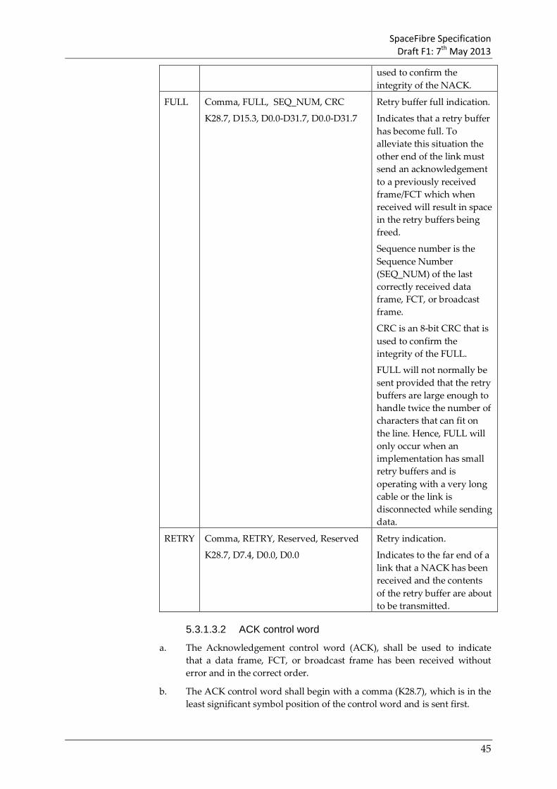
SpaceFibre Specification Draft F1: 7th May 2013
45
used to confirm the integrity of the NACK.
FULL Comma, FULL, SEQ_NUM, CRC
K28.7, D15.3, D0.0-D31.7, D0.0-D31.7
Retry buffer full indication.
Indicates that a retry buffer has become full. To alleviate this situation the other end of the link must send an acknowledgement to a previously received frame/FCT which when received will result in space in the retry buffers being freed.
Sequence number is the Sequence Number (SEQ_NUM) of the last correctly received data frame, FCT, or broadcast frame.
CRC is an 8-bit CRC that is used to confirm the integrity of the FULL.
FULL will not normally be sent provided that the retry buffers are large enough to handle twice the number of characters that can fit on the line. Hence, FULL will only occur when an implementation has small retry buffers and is operating with a very long cable or the link is disconnected while sending data.
RETRY Comma, RETRY, Reserved, Reserved
K28.7, D7.4, D0.0, D0.0
Retry indication.
Indicates to the far end of a link that a NACK has been received and the contents of the retry buffer are about to be transmitted.
5.3.1.3.2 ACK control word
a. The Acknowledgement control word (ACK), shall be used to indicate that a data frame, FCT, or broadcast frame has been received without error and in the correct order.
b. The ACK control word shall begin with a comma (K28.7), which is in the least significant symbol position of the control word and is sent first.

SpaceFibre Specification Draft F1: 7th May 2013
46
c. The second symbol in the ACK control word shall identify the control words as being an ACK control word, and has the value D2.5.
d. The third symbol in the ACK control word shall contain a Sequence Number (SEQ_NUM), which is the Sequence Number of the data frame, FCT, or broadcast frame that is being acknowledged, i.e. that has been correctly received at the far end of the link.
e. The fourth and final symbol in the ACK control word shall contain an 8-bit CRC covering all the symbols in the ACK control word, which is used to confirm the integrity of the ACK when received before its contents are acted upon.
NOTE The CRC includes the data part of the comma K-code.
5.3.1.3.3 NACK control word
a. The Negative Acknowledgement control word (NACK), shall be used to indicate that a data frame, FCT, or broadcast frame has not been received correctly.
b. The NACK control word shall begin with a comma (K28.7), which is in the least significant symbol position of the control word and is sent first.
c. The second symbol in the NACK control word shall identify the control words as being a NACK control word, and has the value D27.5.
d. The third symbol in the NACK control word shall contain a Sequence Number (SEQ_NUM), which is the Sequence Number of the last correctly received data frame, FCT, or broadcast frame.
NOTE All data frames, FCTs, and broadcast frames that have already been sent following that indicated in the NACK will be resent.
e. The fourth and final symbol in the NACK control word shall contain an 8-bit CRC covering all the symbols in the NACK control word, which is used to confirm the integrity of the NACK when received before its contents are acted upon.
NOTE The CRC includes the data part of the comma K-code.
5.3.1.3.4 FULL control word
a. The Full control word (FULL), shall be used to indicate that a retry buffer has become full.
b. The FULL control word shall begin with a comma (K28.7), which is in the least significant symbol position of the control word and is sent first.
c. The second symbol in the FULL control word shall identify the control words as being a FULL control word, and has the value D15.3.
d. The third symbol in the FULL control word shall contain a Sequence Number (SEQ_NUM) of the last data frame, FCT or broadcast frame sent over the SpaceFibre link.

SpaceFibre Specification Draft F1: 7th May 2013
47
e. The fourth and final symbol in the FULL control word shall contain an 8-bit CRC covering all the symbols in the FULL control word, which is used to confirm the integrity of the FULL when received before its contents are acted upon.
NOTE The CRC includes the data part of the comma K-code.
5.3.1.3.5 RETRY control word
a. The Retry control word (RETRY), shall be used to indicate that the contents of the retry buffer is about to be sent.
b. The RETRY control word shall begin with a comma (K28.7), which is in the least significant symbol position of the control word and is sent first.
c. The second symbol in the RETRY control word shall identify the control words as being a RETRY control word, and has the value D7.4.
d. The third and fourth symbols in the RETRY control word are reserved and shall be set to D0.0.
5.3.1.4 Framing control words a. Framing control words shall be used to encapsulate the data frames,
broadcast frames, and idle frames being sent across the link.
NOTE Framing control words are illustrated in Table 5-10.

SpaceFibre Specification Draft F1: 7th May 2013
48
Table 5-10: Data Framing Control words
Name Control word Function SDF Comma, SDF, VC, Reserved
K28.7, D16.2, D0.0-D31.7, D0.0
Start of Data Frame.
Contains type of frame and virtual channel, number.
SBF Comma, SBF, BC, BC_SEQ#
K28.7, D29.2, D0.0-D31.7, D0.0-D31.7
Start of Broadcast Frame.
SIF Comma, SIF, SEQ_NUM, CRC
K28.7, D4.2, D0.0-D31.7, D0.0-D31.7
Start of Idle Frame.
Contains type of frame, and the SEQ_NUM of the last data frame, broadcast frame, or FCT sent.
Note there is no end of idle frame control word.
EDF EDF, SEQ_NUM, CRC_LS, CRC_MS
K28.0, D0.0-D31.7, D0.0-D31.7, D0.0-D31.7
End of Data Frame.
Contains the Sequence Number and 16-bit CRC for the frame.
Note that the EDF starts with K28.0 which is not a comma. This code differentiates all other control words from the EDF control word.
Note the sequence number is over the link NOT per VC.
EBF EBF, RSVD/LATE, SEQ_NUM, CRC
K28.2, D0.0-D1.0, D0.0-D31.7, D0.0-D31.7
End of Broadcast Frame.
Contains the Sequence Number and the 8-bit CRC for the frame.
Note that the EBF starts with K28.2 which is not a comma. This code differentiates all other control words from the EBF control word.
Note the sequence number is over the link NOT per VC.

SpaceFibre Specification Draft F1: 7th May 2013
49
5.3.1.4.2 Sequence Number
a. The Sequence Number (SEQ_NUM), used in the Start of Idle Frame (SIF), End of Data Frame (EDF), End of Broadcast Frame (EBF) and in the FCT (see section 5.3.1.5) and FULL (see section 5.3.1.3.4) control words, shall contain two fields: a polarity flag and a 7-bit Sequence Count.
b. The 7-bit Sequence Count field shall contain a modulo-128 integer, which is incremented each time a new data frame, broadcast frame or FCT is sent.
c. The 7-bit Sequence Count field shall be set to zero following a cold reset or remote flush.
d. The polarity flag shall be set to zero following a cold reset or remote flush.
e. The polarity flag shall be indicated in the bit 7 of the Sequence Number (SEQ_NUM).
f. If the polarity flag is zero, the polarity of the Sequence Number shall be considered positive.
g. If the polarity flag is one, the polarity of the Sequence Number shall be considered negative.
h. The polarity flag shall be inverted every time a new retry is started.
NOTE The polarity flag is used to distinguish frames, ACKs and NACKs sent before a retry starts from those that follow a retry. Each time a new retry starts the polarity bit is flipped to distinguish the new sequence of frames etc. from the old sequence.
5.3.1.4.3 Start of data frame control word
a. The Start of Data Frame control word (SDF), shall be used to indicate the start of a data frame.
b. The SDF control word shall begin with a comma (K28.7), which is in the least significant symbol position of the control word and is sent first.
c. The second symbol in the SDF control word shall identify the control words as being an SDF control word, and has the value D16.2.
d. The third symbol in the SDF control word shall contain the virtual channel number that this data frame is travelling over.
e. The fourth and final symbol in the SDF control word is reserved and shall be set to D0.0.
5.3.1.4.4 Start of broadcast frame control word
a. The Start of Broadcast Frame control word (SBF), shall be used to indicate the start of a broadcast frame.
b. The SBF control word shall begin with a comma (K28.7), which is in the least significant symbol position of the control word and is sent first.
SpaceFibre Specification Draft F1: 7th May 2013
50
c. The second symbol in the SBF control word shall identify the control words as being an SBF control word, and has the value D29.2.
d. The third symbol in the SBF control word shall contain the broadcast channel number that this broadcast frame is travelling over.
e. The fourth and final symbol in the SBF control word shall contain the broadcast sequence number (BC_SEQ#) for the broadcast channel and the Broadcast Type (B_TYPE).
NOTE The broadcast sequence number is used to support the broadcasting of the broadcast frame by SpaceFibre routers, in a similar way to the time-code value in SpaceWire supports the broadcast of time-codes.
5.3.1.4.5 Start of idle frame control word
a. The Start of Idle Frame control word (SIF), shall be used to indicate the start of an idle frame.
b. The SIF control word shall begin with a comma (K28.7), which is in the least significant symbol position of the control word and is sent first.
c. The second symbol in the SIF control word shall identify the control word as being a SIF control word, and has the value D4.2.
d. The third symbol in the SIF control word shall contain the Sequence Number of the last data frame, FCT or broadcast frame sent over the SpaceFibre link.
e. The fourth symbol of the SIF control word shall contain an 8-bit CRC covering the entire control word.
NOTE There is no end of idle frame control word. Idle frames are ended by a SDF, SBF or SIF.
5.3.1.4.6 End of data frame control word
a. The End of Data Frame control word (EDF), shall be used to indicate the end of a data frame.
b. The EDF control word shall begin with the control code K28.0, which is in the least significant symbol position of the control word and is sent first.
NOTE K28.0 is not a comma.
c. The second symbol in the EDF control word shall contain the Sequence Number of the current data frame.
d. The third symbol of the EDF control word shall contain the least significant byte of a 16-bit CRC which covers the entire data frame including the SDF and EDF.
e. The fourth symbol of the EDF control word shall contain the most significant byte of a 16-bit CRC which covers the entire data frame including the SDF and EDF.

SpaceFibre Specification Draft F1: 7th May 2013
51
5.3.1.4.7 End of broadcast frame control word
a. The End of Broadcast Frame control word (EBF), shall be used to indicate the end of a broadcast frame.
b. The EBF control word shall begin with the control code K28.2, which is in the least significant symbol position of the control word and is sent first.
NOTE K28.2 is not a comma.
c. The second symbol in the EBF control word shall contain the LATE flag in bit 0, which indicates that the broadcast frame is late, i.e. has been subject to a retry.
d. The remaining bits (bits 1 to 7) of the second symbol of the EBF control word shall be reserved, set to zero when transmitted and ignored when received.
e. The third symbol in the EBF control word shall contain the Sequence Number of the current broadcast frame.
f. The fourth symbol of the EBF control word shall contain an 8-bit CRC covering the entire broadcast frame including the SBF and EBF.
5.3.1.5 Flow control word a. The Flow control word supports flow control across virtual channels.
NOTE The flow control word is illustrated in Table 5-11.

SpaceFibre Specification Draft F1: 7th May 2013
52
Table 5-11: Flow control word
Name Control word Function FCT FCT, Channel#., SEQ_NUM, CRC
K28.3, D0.0-D31.7, D0.0-D31.7, D0.0-D31.7
Flow Control Token
Indicates that the receive buffer for a specific virtual channel has room for another complete data frame.
FCT is a K-code (K28.3) indicating that this control word is an FCT.
Channel number identifies the virtual channel which this FCT is for.
The SEQ_NUM is a Sequence Number added to the FCT by the quality layer to check for missing, duplicate or out of sequence data frames, broadcast frames and FCTs.
CRC is an 8-bit CRC used to ensure that the FCT does not contain any errors.
a. The Flow Control Token control word (FCT), shall be used to indicate that the receive buffer for the specified virtual channel has room for another complete data frame.
b. The FCT control word shall begin with the K28.3 K-code which is in the least significant symbol position of the control word and is sent first.
c. The second symbol in the FCT control word shall contain the virtual channel number that this FCT is for.
d. The third symbol in the FCT control word shall contain the Sequence Number of the current FCT.
NOTE The FCT shares the same Sequence Numbers as the data frames and broadcast frames.
e. The fourth and final symbol in the FCT control word shall contain an 8–bit CRC covering the entire FCT including the FCT symbol, which is used to check the integrity of the FCT when received, before it is acted upon.
5.3.1.6 Receive error indication control word a. The receive error indication control word is used by the lane layer to
indicate that a disparity error or invalid code error or other form of error was detected in the received data stream.

SpaceFibre Specification Draft F1: 7th May 2013
53
NOTE The receive error indication control words are illustrated in Table 5-12
Table 5-12: Receive error indication control word
Name Control word Function RXERR Error, Reserved, Reserved, Reserved
K0.0, D0.0, D0.0, D0.0
Receive error indication.
Indicates that an error has been detected in the received data stream by the decoder.
Any word containing one or more symbols in error will be replaced by the RXERR control word.
The received data stream is replace by RXERR control words whenever the receive synchronisation state machine is not in the ready state.
b. The receive error indication control word (RXERR), shall be used to indicate that the received data or control word contained an error or is likely to have contained an error.
c. The receive error indication control word shall comprise one error symbol (K0.0) followed by three symbols each set to D0.0.
d. Since the receive error indication control word contains invalid symbols it shall not be transmitted, and is only used in the receiver to indicate receive errors to higher layers.
e. When loss of signal is detected at least one (RXERR) word shall be passed up to the multi-lane or quality layer
f. The RXERR control word may be passed up to the multi-lane or quality layer continuously when the receiver has no signal on its inputs (LOS).
g. Data and control words shall not be passed up to the multi-lane or quality layer when the receiver has no signal on its inputs (LOS).
5.3.2 SpaceFibre Characters
5.3.2.1 SpaceFibre N-Chars a. SpaceFibre data characters shall be directly represented by data symbols
D0.0 to D31.7.
NOTE For example, SpaceFibre data character 0x39 is represented by data symbol D25.1 (see annex A.2).
NOTE SpaceFibre N-chars, data characters, EOPs and EEP are equivalent to SpaceWire N-Chars, data

SpaceFibre Specification Draft F1: 7th May 2013
54
characters, EOPs and EEPs carrying the same type of information, although with a different encoding.
NOTE The SpaceFibre N-Chars are constructed as illustrated in Table 5-13.
Table 5-13: SpaceFibre N-Char Symbols
Name Symbol Function Data D0.0 to D31.7 Each SpaceFibre character
contains one byte of data. Data byte 0x00 is represented by symbol D0.0, data byte 0x01 by D01.0, and so on up to data byte 0xFF which is represented by D31.7.
EOP K29.7 Represents a SpaceFibre EOP. This can occur at any point in the data field of a data frame, indicating the end of a SpaceFibre packet. The data byte following the EOP is the first byte of the next packet.
EEP K30.7 Represents a SpaceFibre EEP. This can occur at any point in the data field of a data frame, indicating that the SpaceFibre packet has terminated with an error. The data byte following the EEP is the first byte of the next packet.
b. The SpaceFibre EOP shall be represented by K29.7.
NOTE K29.7 is not a comma.
c. The SpaceFibre EEP shall be represented by K30.7.
NOTE K30.7 is not a comma.
d. One EOP or EEP symbol shall be allowed to appear anywhere within the data field of a data frame.
e. The EOP and EEP symbols shall indicate the end of a SpaceFibre packet.
f. The data symbol following an EOP or EEP symbol shall be the first data symbol of the subsequent SpaceFibre packet.
5.3.2.2 Fill control character a. The Fill control character shall be represented by K27.7
NOTE K27.7 is not a comma.
NOTE The Fill control character is constructed as illustrated in Table 5-14.

SpaceFibre Specification Draft F1: 7th May 2013
55
NOTE This character is called a Fill control character because it is used to fill out space at the end of a SpaceFibre packet.
Table 5-14: Fill control word Symbol
Name Symbol Function Fill K27.7 Used when there is not a multiple
of 4 N-Chars in an output VCB to be sent. For example, if there are three N-Chars in an output VCB and the last one is an EOP, it is important to send this tail end of the SpaceFibre packet, without waiting for data from another packet to be added to the buffer. Since SpaceFibre sends data in words of four N-Chars each it is necessary to have a character that will fill out the space at the end of the words. A sequence of Fills will contain one, two or three Fills but never any more.
b. The Fill character shall be allowed to appear only after an EOP or EEP and is used, when required, to fill the remaining characters in the word containing the EOP or EEP.
NOTE This can be used to support 32-bit alignment of the VCBs. An example showing several small packets in part of a frame, some 32-bit aligned and others packed into 32-bits, is provided in Figure 5-2, where D represents a data character, E an EOP, and F a Fill.
D D D D
D E F F
F F D D
D D D D
E F F F D D E D
D D D D
E F F F Figure 5-2 Fills in a virtual channel buffer
c. When the data available from the output virtual channel buffer to be put in the data frame is not a multiple of four N-Chars, Fill characters shall be added to the end of the data field to pad the last word out to a complete data word.

SpaceFibre Specification Draft F1: 7th May 2013
56
NOTE This will happen when there is one or more EOPs or EEPs in the output VCB. If following the last EOP or EEP added to the output VCB, no more data has been added, there might not be a multiple of 4 N-chars in the buffer. When the last data incorporating the EOP or EEP is read out of the output VCB the space following the EOP or EEP must be filled with Fill characters to form a complete 4 N-Char data word.
d. Fills shall be transported across the SpaceFibre link and placed in the input virtual channel buffer at the receiving end of the link.
5.3.3 Frame Format a. A frame shall contain user data, from a virtual channel or broadcast
channel, or idle data.
b. Three types of frame shall be supported: data frame, broadcast frame, idle frame.
5.3.3.1 Data frame a. A data frame shall start with a start of data frame (SDF) control word.
NOTE The data frame is illustrated in Figure 5-3.
0 7 8 15 16 23 24 31
COMMA SDF VC RESERVED DATA 1 LS DATA 1 DATA 1 DATA 1 MS DATA 2 LS DATA 2 DATA 2 DATA 2 MS
... ... ... ... DATA N LS DATA N DATA N DATA N MS
EDF SEQ_NUM CRC_LS CRC_MS Figure 5-3 Data Frame Format
b. A data frame shall end with an end of data frame (EDF) control word.
c. A data frame shall contain between one and 64 data words each.
d. Each data word shall contain four SpaceFibre N-Chars or Fills.
e. The virtual channel (VC) field in the data frame shall identify the VC sending the data frame and into which it is to be received.
f. The reserved field in the start of data frame (SDF) is reserved and shall be set to D0.0 and shall be ignored by the receiver when the word is identified.
g. The end of data frame shall contain a 16-bit CRC covering the SDF control word, the data in the data frame, and the EDF control word.

SpaceFibre Specification Draft F1: 7th May 2013
57
h. The Sequence Number (SEQ_NUM) in the end of frame shall contain the Sequence Number for the current frame.
5.3.3.2 Idle frames a. An idle frame shall start with an idle frame control word.
NOTE An idle frame is illustrated in Figure 5-4. 0 7 8 15 16 23 24 31
COMMA SIF SEQ_NUM CRC SEED LS SEED SEED SEED MS
PRBS 1 LS PRBS 1 PRBS 1 PRBS 1 MS PRBS 2 LS PRBS 2 PRBS 2 PRBS 2 MS
... ... ... ... PRBS N LS PRBS N PRBS N PRBS N MS
Figure 5-4 Idle Frame Format
b. An idle frame shall contain between zero and 64 data words.
c. An idle frame shall end with the start of a data frame, broadcast frame, or next idle frame.
NOTE There is no end of idle frame control word.
d. The Sequence Number (SEQ_NUM) shall be the Sequence Number of the last sent data frame, broadcast frame or FCT.
e. The PRBS in an idle frame shall contain a pseudo-random bit sequence (PRBS).
NOTE Sending a PRBS avoids an EMI emission peak when idles frames are being transmitted and enables a PRBS test to be made at the receiver.
f. The Seed field is the first data word following the start of idle frame (SIF) control word and shall be set to a pseudo-random number which is used to seed the PRBS words in the idle frame.
NOTE This permits a SpaceFibre receiver to decode and check the PRBS in the idle frame. This can be used to check the health of the physical layer, after lane initialisation.
g. The PRBS shall be generated using the algorithm described in section 5.5.3.2.3.
h. At the end of an idle frame the next pseudo-random word that would have been sent in the next data word of an idle frame shall be kept and used as the seed value of the next data frame.
NOTE In this way the PRBS carries on across a sequence of idle words.
i. The Seed field of the first idle frame following a cold reset shall be set to 0xFFFF.

SpaceFibre Specification Draft F1: 7th May 2013
58
j. An idle frame shall be terminated as soon as there is a broadcast frame, or data frame to send.
k. An idle frame shall be terminated in any case when 64 PRBS words have been sent.
NOTE This means that the length of the idle frame can contain zero to 64 idle words depending on when there are more broadcast or data frames to send.
l. An idle frame shall contain at least a start of idle frame (SIF) control word.
5.3.3.3 Broadcast frame a. A broadcast frame shall start with a start of broadcast frame (SBF) control
word.
NOTE The broadcast frame is illustrated in Figure 5-5.
0 7
8 15 16 23 24 31
COMMA SBF BC B_SEQ#/B_TYPE DATA 1 MS DATA 1 DATA 1 DATA 1 MS DATA 2 LS DATA 2 DATA 2 DATA 2 MS
EBF RSVD/LATE SEQ_NUM CRC Figure 5-5 Broadcast Frame Format
b. A broadcast frame shall end with an end of broadcast frame (EBF) control word.
c. A broadcast frame shall contain two data words each containing four data bytes.
d. The broadcast channel (BC) field in the SBF control word shall identify the broadcast channel transmitting and receiving the broadcast frame.
e. The B_SEQ#/B_TYPE field shall contain two sub-fields: a 3-bit Broadcast Sequence Number (B_SEQ#) field in bit positions 7:5 and a 5-bit Broadcast Type (B_TYPE) field in bit positions 4:0.
f. The Broadcast Sequence Number (B_SEQ#) field in the SBF shall contain an incrementing sequence number specific to the broadcast channel.
NOTE Each BC has its own broadcast sequence number (B_SEQ#) which is used to support the broadcast of the broadcast frame across a SpaceFibre network.
g. The Broadcast Type (B_TYPE) field shall contain a broadcast type, which indicates the type of broadcast message and the meaning of the subsequent eight data bytes.

SpaceFibre Specification Draft F1: 7th May 2013
59
h. The end of broadcast frame shall contain a RSVD/LATE field which contains two sub-fields: a 7-bit Reserved (RSVD) field and a 1-bit LATE flag in the least significant position.
i. The Reserved (RSVD) field in the EBF shall be set to zero when transmitted and ignored when received.
j. The LATE flag in the EBF shall be set to one when the broadcast frame is resent during a retry, and set to zero otherwise.
NOTE This is used to signal to a receiving node that a broadcast frame has been delayed due to one or more retries. If the broadcast message contains time synchronisation the end user application might decide to ignore the broadcast message because it was late. If the broadcast message contains event signalling information it might still be useful to the application even though it arrives late.
k. The Sequence Number (SEQ_NUM) in the end of broadcast frame shall contain the sequence number of the frame.
NOTE This sequence number is used to support retry.
l. The end of broadcast frame shall contain an 8-bit CRC covering the SBF control word, the data in the data frame, and the EBF control word.
5.3.4 SpaceFibre packet format a. A SpaceFibre packet shall comprise a destination address, a cargo and an
end of packet (EOP) or error end of packet (EEP) marker.
NOTE This is the same format as a SpaceWire packet.
b. The destination address shall comprise zero or more data characters that describe the path to or the identity of the destination of the packet.
c. The cargo shall contain the data that is to be transferred from the source of the packet to the destination of the packet.
d. A SpaceFibre packet shall normally be terminated by an EOP marker, which signals the end of one packet and the start of the next packet.
e. If an error has occurred in a packet resulting in some of the data in the packet being lost, the packet shall be terminated by an EEP.
f. The data character following an EOP or EEP marker is the first data character of the next packet, which is usually the destination address or the first part of the destination address.
g. A SpaceFibre packet shall be able to take on any length.
h. Packets of zero length, i.e. an EOP or EEP followed immediately by another EOP or EEP, shall not be generated by a packet source.
NOTE Zero length packets can occur on a network after an error, but will be discarded by a routing switch.

SpaceFibre Specification Draft F1: 7th May 2013
60
5.3.5 Control word and frame precedence a. During lane initialisation, prior to a link being established, only the
following Lane Layer Control Words shall be sent: SKIP, INIT1, iINIT1, INIT2, iINIT2, INIT3, IDLE.
b. During lane initialisation the Lane Layer Control Words shall have the following precedence:
(1) SKIP, highest precedence
(2) INIT1, iINIT1, INIT2, iINIT2, INIT3
(3) IDLE, lowest precedence
c. Once one or more lanes have been established to form a link, the control words and frames shall have the following precedence:
(1) SKIP
(2) LOST_SIGNAL
(3) Standby
(4) LSYNC
(5) RETRY
(6) Broadcast frame
(7) ACK/NACK
(8) FCT
(9) Data frame
(10) FULL
(11) Idle frame
(12) IDLE, lowest precedence.
NOTE It is not possible for an ACK and NACK to be waiting to be sent at the same time: one replaces the other.
d. A SKIP control word shall be inserted within a data frame, broadcast frame or idle frame.
e. A LOST_SIGNAL control word shall be inserted within a broadcast, data or idle frame.
f. A Standby control word shall be inserted within a broadcast, data or idle frame.
g. An LSYNC control word shall be inserted within a broadcast, data or idle frame.
h. A RETRY control word shall be inserted within a broadcast, data or idle frame.
i. A broadcast frame shall be inserted within a data frame.
j. A broadcast frame shall end an idle frame.
k. An ACK control word shall be inserted within a data or idle frame.
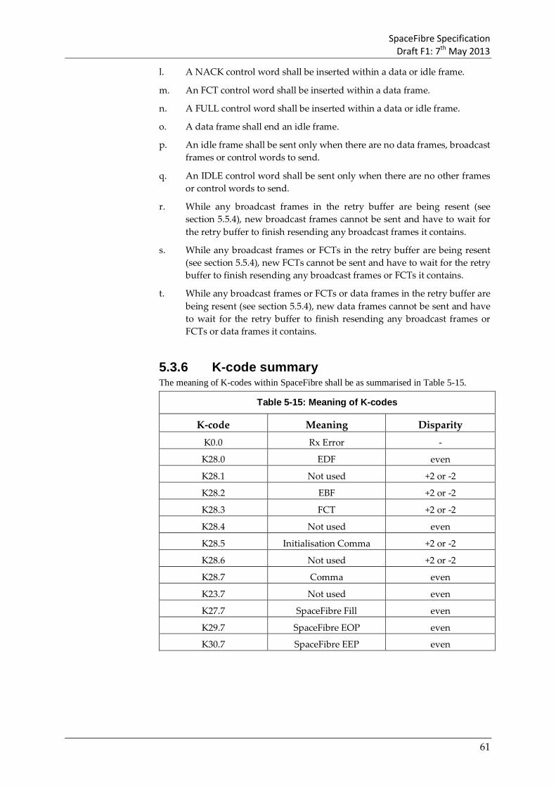
SpaceFibre Specification Draft F1: 7th May 2013
61
l. A NACK control word shall be inserted within a data or idle frame.
m. An FCT control word shall be inserted within a data frame.
n. A FULL control word shall be inserted within a data or idle frame.
o. A data frame shall end an idle frame.
p. An idle frame shall be sent only when there are no data frames, broadcast frames or control words to send.
q. An IDLE control word shall be sent only when there are no other frames or control words to send.
r. While any broadcast frames in the retry buffer are being resent (see section 5.5.4), new broadcast frames cannot be sent and have to wait for the retry buffer to finish resending any broadcast frames it contains.
s. While any broadcast frames or FCTs in the retry buffer are being resent (see section 5.5.4), new FCTs cannot be sent and have to wait for the retry buffer to finish resending any broadcast frames or FCTs it contains.
t. While any broadcast frames or FCTs or data frames in the retry buffer are being resent (see section 5.5.4), new data frames cannot be sent and have to wait for the retry buffer to finish resending any broadcast frames or FCTs or data frames it contains.
5.3.6 K-code summary The meaning of K-codes within SpaceFibre shall be as summarised in Table 5-15.
Table 5-15: Meaning of K-codes
K-code Meaning Disparity K0.0 Rx Error -
K28.0 EDF even
K28.1 Not used +2 or -2
K28.2 EBF +2 or -2
K28.3 FCT +2 or -2
K28.4 Not used even
K28.5 Initialisation Comma +2 or -2
K28.6 Not used +2 or -2
K28.7 Comma even
K23.7 Not used even
K27.7 SpaceFibre Fill even
K29.7 SpaceFibre EOP even
K30.7 SpaceFibre EEP even

SpaceFibre Specification Draft F1: 7th May 2013
62
5.3.7 Control word symbol summary The data values assigned to particular control word symbols within SpaceFibre shall be as summarised in Table 5-16.
Table 5-16: Meaning of control word symbols
D-code Meaning Disparity D14.6 / D17.1 LLCW/i_LLCW even
D23.3 LSYNC odd
D2.5 ACK odd
D27.5 NACK odd
D7.4 RETRY odd
D16.2 SDF odd
D29.2 SBF odd
D4.2 SIF odd
D15.3 FULL odd
D31.3 SKIP odd
D15.6 IDLE odd
D6.2 / D25.5 INIT1/iINIT1 even
D6.5 / D25.2 INIT2/iINIT2 even
D24.1 INIT3 odd
D30.3 STANDBY odd
D4.3 LoS odd
5.4 Network layer In this section the SpaceFibre network layer is specified.
5.4.1 Network structure a. A SpaceFibre network shall comprise two or more SpaceFibre nodes and
zero or more SpaceFibre routing switches.
b. SpaceFibre nodes and SpaceFibre routing switches shall be interconnected with SpaceFibre links.
c. A routing switch shall be used to interconnect many nodes together so that they can communicate one with another without having to have a dedicated point to point link from each node to every other node that it wishes to communicate with.
5.4.1.2 Links a. A SpaceFibre link shall connect two SpaceFibre devices.
b. A SpaceFibre link shall comprise one or more lanes.

SpaceFibre Specification Draft F1: 7th May 2013
63
5.4.1.3 Nodes a. Nodes shall host the applications using the SpaceFibre network and
provide one or more SpaceFibre interfaces to the network.
5.4.1.4 Routing Switch a. A SpaceFibre routing switch shall transfer packets from the input port of
the switch where the packet arrives, to a particular output port determined by the packet destination address.
5.4.2 Packet switching scheme a. A routing switch shall use the leading data character of a packet to
determine which output port the packet is to be forwarded through.
b. A routing table within the routing switch shall specify the mapping from value of the leading data character to the output port and also whether the leading data character is to be removed before the packet is switched to the output port.
c. The routing table shall be as illustrated in Table 5-17.
Table 5-17: Routing switch addresses
Leading data character
Address type
Port packet is routed to Header deletion
0 Path Internal Configuration Port Always
1-31 Path Physical Output Ports 1-31 respectively
Always
32-254 Logical A look-up table specifies the mapping from the leading data character (logical address) to the output port the packet is to be forwarded through. There is one entry in this table for each value of the logical address (32-255). Each entry is configured to specify the output port to be used for each possible logical address.
Optional on each output port. Header deleted if the physical output port is a gateway between distinct regions. Header can also be deleted on final link to a node.
255 Logical Reserved logical address. Not applicable.
NOTE A leading data character with a value of 0 results in the packet being routed to the routing switch configuration port.
NOTE A leading data character with a value of 6 results in the packet being routed to output port 6.
NOTE A leading data character with a value of 49 results in the packet being routed to the output

SpaceFibre Specification Draft F1: 7th May 2013
64
port that is referred to in location 49 of the routing table within the routing switch.
d. A NULL routing table entry shall mean that the routing table entry is undefined and if referenced results in the packet being spilt and an invalid address error being recorded.
e. A logical address shall not be allowed to access the internal configuration port (port 0) which shall be accessed using path addressing only.
f. Address 255 is reserved for future use and shall not be used.
5.4.2.2 Path addressing a. A path address shall describe the path through the SpaceFibre network
from the source of the packet to its destination.
b. A path address shall comprise one or more data characters at the start of a packet, with each data character in the range 0-31.
c. When a SpaceFibre packet arrives at a routing switch and the leading data character is in the range 0 to 31, the leading data character shall be removed and the packet shall be switched out of the port indicated by that data character.
NOTE Removing the leading path address character after it has been used exposes the next path address character for use at the next router on the path to the destination.
d. The complete path address shall comprise a sequence of data characters, one for each router to be encountered on the path from the packet source to the packet destination.
e. A SpaceFibre routing switch shall always implement path addressing.
5.4.2.3 Logical addressing a. A logical address shall comprise a single data character at the start of a
packet, with a value in the range 32 to 255.
b. When a SpaceFibre packet arrives at a routing switch and the leading data character is in the range 32 to 255, the leading data character shall be used as an index into a routing table to determine which port the packet is to be forwarded through.
c. The logical address shall not be removed from the packet when the packet is forwarded.
5.4.2.4 Header deletion a. Header deletion shall always be applied to path addresses.
b. When header deletion applies, the leading data character (destination identifier) of each packet shall be deleted before the packet is sent out of the specified output port.

SpaceFibre Specification Draft F1: 7th May 2013
65
c. One and only one data character (destination identifier) shall be deleted by each routing switch with header deletion enabled that is traversed by the packet.
5.4.2.5 Routing switch a. A SpaceFibre routing switch may implement logic addressing as well as
path addressing.
b. The number of ports on a routing switch shall be limited to 32 including the internal configuration port, port 0.
NOTE This is because only ports 0 to 31 can be accessed by path addressing.
c. Routing switches may be implemented with any number of ports from 3 to 32, including the internal configuration port.
d. Accessing an output port that does not exist shall result in the packet being spilt and an invalid address error being recorded.
5.4.2.6 Routing switch operation a. The SpaceFibre routing switch shall operate as follows:
1. When a packet arrives at a routing switch the output port that it is to be forwarded through shall be determined from the leading data character of the packet and the routing table.
2. The packet shall be switched to the virtual channel in the specified output port that has the same virtual channel number as the virtual channel on which the packet arrived in the routing switch input port.
3. If the virtual channel in the output port is free, i.e. not currently transmitting a packet, it shall be allocated to transmit the newly arrived packet.
4. Once the connection has been made between the input port virtual channel and the output port virtual channel, data will be forwarded from the input virtual channel to the output virtual channel as they arrive, provided that the output virtual channel is able to accept them.
5. If the output virtual channel is not able to accept more data, the input virtual channel shall hold its data until the output virtual channel become ready to accept more data.
6. The virtual channel in the output port shall not change the connection between an input port and an output port until the packet that it is currently transmitting has been sent or terminated following an error.
7. If the virtual channel in the required output port is busy sending a packet from another input port, the newly arrived packet shall wait at the input port until the assigned output port is free to transmit the new packet.

SpaceFibre Specification Draft F1: 7th May 2013
66
8. When a virtual channel in an output port finishes transmission of its current packet, it shall be available to accept a packet from another input port.
9. If the specified output port does not have a virtual channel with the same virtual channel number as that on which the packet arrived in the input port, the packet shall be split and an invalid output port error recorded by the routing switch.
5.4.2.7 Regional logical addressing a. SpaceFibre shall also support regional logical addressing which is a
special case of logical addressing.
b. A routing switch shall be configurable to remove the logical address character at the start of a packet when a packet is forwarded.
NOTE Removal of the logical address character exposes a second data character which is the path or logical address to use at the next routing switch. This mechanism enables more than 224 nodes to be access using logical addressing.
5.4.3 Messages broadcasting a. Message broadcasting is yet to be defined.
5.4.4 Network management a. The network management is yet to be defined.
5.5 Quality layer In this section the Quality Layer of SpaceFibre is specified.
5.5.1 Virtual channels
5.5.1.1 Virtual channel buffering a. The application interface to the SpaceFibre CODEC shall comprise one or
more output virtual channel buffers and the same number of input virtual channel buffers.
b. There shall be a maximum of 256 virtual channels.
c. There shall be an output virtual channel buffer and an input virtual channel buffer for each virtual channel.
d. A particular virtual channel shall be identified by its virtual channel number.

SpaceFibre Specification Draft F1: 7th May 2013
67
e. An output virtual channel buffer shall be large enough to hold at least 256 SpaceFibre N-Chars.
NOTE This corresponds to one full SpaceFibre data frame.
f. To send a SpaceFibre packet over a particular virtual channel the application shall write the N-Chars forming the SpaceFibre packet into the virtual channel buffer, starting with the leading N-Chars of the SpaceFibre packet.
g. If the output virtual channel buffer becomes full the application shall wait until there is more room in the output virtual channel buffer.
NOTE SpaceFibre packets can be any length. Packets greater than the size of the output virtual channel buffer will not fit into the buffer and will have to be written in as space is made available in the buffer when data is read out and sent over the SpaceFibre link.
h. As soon as one SpaceFibre packet has been written into the output virtual channel buffer, it shall be possible to start writing the next SpaceFibre packet to be sent over that virtual channel, provided that there is room in the output virtual channel buffer for at least one more N-Char.
NOTE This means that it is possible to have many small packets waiting for transmission in the output virtual channel buffer.
i. SpaceFibre packets shall be sent over a virtual channel in the order in which they are written into the output virtual channel buffer for that virtual channel.
j. An output virtual channel at one end of a SpaceFibre link shall be paired with the input virtual channel at the other end of the SpaceFibre link which has the same virtual channel number.
k. When SpaceFibre packets are received they shall be placed in the input virtual channel buffer for the virtual channel that they were sent over.
l. An input virtual channel buffer shall be large enough to hold at least 256 SpaceFibre N-Chars.
NOTE This value is implementation dependent, but normally the buffer size would be sufficient for at least 1024 SpaceFibre N-Chars.
m. SpaceFibre N-Chars shall appear in an input virtual channel buffer in the same order in which they were written into the corresponding output virtual channel buffer at the other end of the link.
n. When there are N-Chars available in an input virtual channel buffer, the host application shall be informed that there is data available to read from that input virtual channel buffer.
o. The host application can read data from the input virtual channel buffer whenever it wants to, provided that there is data available in the input channel buffer.

SpaceFibre Specification Draft F1: 7th May 2013
68
p. When during initialisation the INIT3 capability field requests a remote flush, all output virtual buffers shall be flushed and for each output virtual buffer, if the last character written by the host application was not an EOP, all new data characters will be discarded up to and including the next EOP.
NOTE This is similar to SpaceWire error handling, which spills the current packet being transmitted when a disconnection error occurs. This ensures that the receiver will not get an incomplete packet with an invalid header.
q. When during initialisation the INIT3 capability field requests a remote flush, all input virtual buffers shall be flushed and for each input virtual buffer, an EEP shall be the next symbol read by the host application if the last symbol read was not an EOP.
NOTE This is equivalent to SpaceWire error handling, which uses the EEP to indicate at the receiver side that the link was disconnected and that the last chuck of packet provided is in error.
5.5.1.2 Segmentation a. Each output virtual channel buffer shall keep track of the number of N-
Chars written into it and the number read out.
b. When there are at least 256 N-Chars in the output virtual channel buffer, or it contains at least one EOP or EEP or the priority level is 0, 1, 2 or 3, that virtual channel buffer shall indicate that is has data ready to form a data frame to a medium access controller, which controls which output channel is to be permitted to next send a data frame over the SpaceFibre link.
c. When informed that it is now permitted to send a data frame over the SpaceFibre link, an output virtual channel buffer shall pass up to 256 N-Chars, to the medium access controller for sending over the SpaceFibre link.
d. If the output virtual channel buffer contains one or more EOPs or EEPs and less than 256 N-Chars, it shall send all the N-chars it contains to the medium access controller.
e. If the number of N-Chars being sent in a data frame is not a multiple of four N-Chars, one, two or three Fills shall be added to pad out the last data word of the data frame.
f. When a data frame is received, the N-Chars it contains shall be placed in the appropriate input virtual channel buffer.

SpaceFibre Specification Draft F1: 7th May 2013
69
5.5.1.3 Flow control
5.5.1.3.1 TX FCT Control
a. Each input virtual channel buffer shall keep track of the number of N-Chars and Fills written into it from the SpaceFibre receiver and read out, using an input space counter for that input virtual channel buffer.
NOTE If a frame contains an EOP or EEP it is possible that as well as N-Chars it contains some Fills which are used to pad out the number of N-Chars to a multiple of four. At the link level these Fills are treated in the same way as N-Chars and are transferred across the link and placed in the input virtual channel buffer at the far end of the link.
b. On cold-reset or remote flush, the input space counter shall be set to the amount of space in the buffer, counted as the number of N-Chars and Fills the buffer can contain.
c. On warm-reset, the input space counter shall not be modified.
d. If the value of the input space counter is greater than or equal to 256 the input VC buffer shall request the transmitter to send an FCT.
NOTE After cold reset this can result in several FCTs being sent for a virtual channel if its input buffer can hold more than 256 N-Chars or Fills.
e. For each FCT sent by a specific input virtual channel, 256 shall be subtracted from the corresponding input space counter to reserve that much space for the N-Chars and Fills that the FCT will permit to be sent from the far end of the link.
NOTE An FCT is effectively exchanged for 256 N-Chars and Fills.
f. Each time the end user application reads out an N-Char or Fill from the input VC buffer, the input space counter shall be incremented by one.
g. The input space counter shall indicate the amount of space available in the input virtual channel buffer.
h. When FCTs are being requested to be sent for several different virtual channel buffers, they shall be arbitrated fairly.
i. The input space counter shall have a minimum size of 256 N-Chars or Fills.
NOTE Normally the input VC buffers and hence input space counter would be significantly larger than 256.
5.5.1.3.2 RX FCT Control
a. Each output virtual channel buffer shall contain an FCT credit counter which shall indicate how much more data it is permitted to send.
b. On cold-reset or remote flush, the FCT credit counter shall be set to zero.

SpaceFibre Specification Draft F1: 7th May 2013
70
c. On warm-reset, the FCT credit counter shall not be modified.
d. When an FCT is received for a particular virtual channel, 256 shall be added to the FCT credit counter for that virtual channel.
e. When a data frame is sent by a particular virtual channel, the number of N-Chars and Fills sent in the data frame shall be subtracted from the FCT credit counter.
f. A virtual channel shall not be permitted to send data frames when its FCT credit counter is less than 256, unless its output VCB contains an EOP or EEP, in which case it can send N-Chars and Fills up to the limit indicated by the FCT transmit credit counter for that virtual channel.
g. When a data frame is ready to send, the amount of data in the frame shall be compared to the value of the FCT credit counter and if the FCT credit counter is greater than or equal to the amount of data in the frame waiting to be sent, that data frame shall be sent.
h. If the FCT credit counter overflows, the FCT causing the overflows shall be discarded, the FCT credit counter saturated to its maximum value and the error reported in a status register.
5.5.1.4 Medium access control a. A medium access controller shall determine which virtual channel is
allowed to send the next data frame.
b. Only output virtual channel buffers indicating that they have data ready to form a data frame, shall be permitted to compete for sending the next data frame.
c. Only virtual channels whose FCT credit counter indicates that its input virtual channel buffer at the far end of the SpaceFibre link has room to accept the amount of data to be sent in the next data frame shall be permitted to compete for sending the next data frame.
d. Each output virtual channel buffer, with data ready to send in its output virtual channel buffer and space available in its input virtual channel buffer at the far end of the SpaceFibre link (a ready virtual channel), shall compete for sending the next data frame, if it is allowed to do so in the current time slot.
5.5.1.4.2 Quality of service
a. Each virtual channel shall support the following qualities of service: priority, bandwidth reservation, and scheduled.
b. It shall be possible to set the quality of service parameters of each virtual channel individually so that different qualities of service can be applied to different virtual channels.
c. Upon cold reset the quality of service for each virtual channel shall be set to lowest priority.
5.5.1.4.3 Schedule
a. Time shall be split into a number of time-slots of equal duration specified by the time slot duration management parameter, see section 5.9.2.

SpaceFibre Specification Draft F1: 7th May 2013
71
NOTE Typical time-slot duration is 100 μs.
b. Time for use in the scheduled quality of service shall be taken from the local time register, which is regularly updated by the time-distribution broadcast channels.
c. The local time register shall provide an indication of when one time-slot finishes and the next one starts, together with the number of that time-slot.
d. The number of time-slots in a schedule shall be specified by a management parameter, see section 5.9.2.
e. The schedule shall indicate in which time-slots a particular virtual channel is permitted to send data frames.
NOTE For each virtual channel there will be a list of time-slots in which it is allowed to send data.
f. It shall be possible for several virtual channels to be scheduled to send data in the same time-slot.
g. If two or more virtual channels are scheduled to send data in the same time-slot, the medium access controller shall send data from the virtual channel with the highest precedence, see section 5.5.1.4.4.
h. When a time-slot starts, for which a specific virtual channel is scheduled to send data, has data ready to send in its output virtual channel buffer and has space in its input virtual channel buffer at the far end of the SpaceFibre link, it shall compete with other virtual channels for sending frames over the link based on its precedence.
i. A virtual channel that is not scheduled in the current time-slot shall not be allowed to compete for sending data over the link.
j. At the end of the time-slot, any virtual channel sending data frames shall cease sending them after the current data frame has been sent, unless that particular virtual channel buffer is also scheduled to send data in the next time-slot.
k. The scheduling of traffic from virtual channels over the SpaceFibre link, shall take into account the fact that at the start of a time-slot, there might still be a complete data frame to send over the link from the previous time-slot.
l. When a SpaceFibre network is not required to use the scheduling quality of service, the schedule for each virtual channel shall be set to use all time-slots.
5.5.1.4.4 Precedence
a. A virtual channel shall compete with other virtual channels for sending frames over the link based on the current precedence of the virtual channel and its schedule.
b. The medium access controller shall use the precedence of each virtual channel to determine which ready virtual channel is permitted to send a data frame.

SpaceFibre Specification Draft F1: 7th May 2013
72
c. The precedence of each virtual channel shall be compared when the last word of the previous frame is being passed to the framing layer for transmission.
d. The virtual channel buffer that is ready and which has the highest precedence shall be permitted to send the next data frame.
e. The precedence of a virtual channel shall be determined by its quality of service parameters and its bandwidth credit.
f. The precedence of a virtual channel shall be calculated as the sum of the priority precedence plus the current value of bandwidth credit for that virtual channel.
Precedence = Priority Precedence + Bandwidth Credit
NOTE The priority precedence for a virtual channel is derived directly from its priority level parameter.
NOTE Precedence is calculated taking into account the qualities of service mechanisms outlined in Table 5-18.
g. If the Bandwidth credit is below the Minimum Bandwidth Credit Threshold, the Priority Precedence shall be set to zero.
Table 5-18 Precedence for Different Qualities of Service
Quality of Service Precedence
Priority A priority virtual channel is only allowed to send data when no other virtual channel with a higher priority setting is ready to send data.
Several priority levels are supported.
If two or more priority virtual channels set to the same priority level are both ready to send data, the one with the highest bandwidth credit is permitted to send a data frame first.
If a SpaceFibre network is required to operate using priority only, each virtual channel has to be assigned a different priority level.
Best effort quality of service is obtained when a virtual channel has its priority quality of service parameter set to the lowest priority.
Bandwidth Reserved Bandwidth reservation determines the precedence of a virtual channel based on the link bandwidth reserved for that virtual channel and its recent link utilisation.
Each virtual channel computes a bandwidth credit based on the link bandwidth reserved for that virtual channel and its recent link utilisation.

SpaceFibre Specification Draft F1: 7th May 2013
73
A virtual channel with large reserved bandwidth and low recent bandwidth utilisation has high bandwidth credit. A virtual channel with similar reserved bandwidth and higher recent bandwidth utilisation has lower bandwidth credit.
Within a specific priority level virtual channels compete for sending the next data frame based on their current bandwidth credit.
A bandwidth reserved virtual channel is only allowed to send data when there are no other virtual channels with higher priority that are ready to send data, and the virtual channel has the highest bandwidth credit of all of the virtual channels of the same priority level that are ready to send data.
If a SpaceFibre network that just uses bandwidth reservation is required, this can be achieved by simply setting all virtual channels to use the same priority level.
Scheduled Scheduled quality of service provides a means of ensuring fully deterministic allocation of SpaceFibre network resources.
Time is separated into a series of time-slots during which a virtual channel can be scheduled to send data. When a time-slot arrives in which a virtual channel is scheduled, it can send data based on its precedence.
During all the other time-slots when the virtual channel is not scheduled to send data, it is not permitted to send any data even when no other virtual channel has data to send.
If a virtual channel scheduled in the current time-slot does not have data to send during its time-slot or does not have space in its VCBs at the far end of the link, other virtual channels allowed to transmit in the current time-slot are permitted to use the otherwise wasted bandwidth.
If each virtual channel uses a different slot to send data, a simple scheduled quality of service is provided, without considering priority or bandwidth reservation.
5.5.1.4.5 Bandwidth credit
a. Bandwidth Credit shall be updated every time a data frame has been sent on any virtual channel.
b. If no data frame is sent, the Bandwidth Credit shall be updated after an interval approximately equal to the time it takes to send a full data frame, or less.

SpaceFibre Specification Draft F1: 7th May 2013
74
NOTE The clause means that every 66 words or less the Bandwidth Credit is updated.
NOTE When no data is sent the Used Bandwidth is zero, see section 5.5.1.4.5g.
c. The Available Bandwidth shall be measured for the SpaceFibre links as the number of data or control words that can be sent since the Bandwidth Credit was last updated, allowing for multi-lane operation.
NOTE . When specifying a bandwidth allocation for a virtual channel it is useful to think in terms of the percentage of overall link capacity being allocated. It is then straightforward to allocate a percentage of the bandwidth to each virtual channel, leaving some spare capacity for possible broadcast messages and general contingency.
NOTE When setting the bandwidth allocations each virtual channel is allocated a little bit more bandwidth than it requires, so that the counter is nominally saturated, and the sum of all virtual channel bandwidth allocations is less than 100%, to leave some margin for broadcasts, ACKs, FCT, etc.
d. A virtual channel shall specify a portion of the Link Bandwidth that it wishes or expects to use, i.e. its Expected Bandwidth Percentage, including the overhead due to the use of frame delimiters and other control words.
NOTE This information is to be provided for all virtual channels regardless of the quality of service they are providing, using management parameters.
NOTE The overhead for the frame delimiters is normally 2 words for every 64 data words. The Expected Bandwidth Percentage assigned to each virtual channel should account for this protocol overhead.
NOTE The overhead related with the sending of other control words is normally two words, an ACK and an FCT for every data frame sent in both directions. The sum of all Expected Bandwidth Percentages should account for this overhead. For example, if broadcasts are no being sent, the sum of all Expected Bandwidth Percentages should not exceed the 66/(66+2) = 97% of the link bandwidth.
e. The Expected Bandwidth Percentage shall be greater than zero for all virtual channels, even when they are not expected to be used.

SpaceFibre Specification Draft F1: 7th May 2013
75
f. Used Bandwidth shall be the amount of data words sent by a particular virtual channel, including frame delimiters, since the last time the Bandwidth Credit was updated.
NOTE This is zero for all virtual channels except for the one that sent a data frame.
g. Bandwidth Credit shall be calculated independently for each virtual channel as follows:
)(∑ −=centagendwidthPerExpectedBa
dthUsedBandwiandwidthAvailableBreditBandwidthC
h. Bandwidth Credit shall be permitted to go negative.
NOTE A negative value indicates that the virtual channel is using more than its expected amount of link bandwidth.
i. Bandwidth Credit shall saturate at plus or minus the Bandwidth Credit Limit, i.e. if the Bandwidth Credit reaches a Bandwidth Credit Limit it is set to the value of the Bandwidth Credit Limit.
j. The Bandwidth Credit Limit shall be set to a value not smaller than the Link Bandwidth.
NOTE This leads to a virtual channel reaching positive saturation after 1 second when no data is being sent by that virtual channel. After this period of time the virtual channel effectively starts to forget what it has send or not sent previously.
k. When the Bandwidth Credit for a virtual channel reaches the Positive Bandwidth Credit Limit and stays at that value for at least the Virtual Channel Idle Time Limit, the virtual channel shall indicate in a status register that it is idle and using much less bandwidth than expected.
NOTE A network management application is able to use this information to check correct utilisation of link bandwidth by its various virtual channels.
NOTE The Virtual Channel Idle Time Limit is a configuration parameter that applies to all virtual channels. A typical value is 1 ms.
l. A Minimum Bandwidth Credit Threshold shall be set, below which a virtual channel is deemed to be using more than its allocated bandwidth.
m. The Minimum Bandwidth Credit Threshold shall be set at approximately 90% of the value of the Negative Bandwidth Credit Limit.
n. When the Bandwidth Credit for a virtual channel reaches the Minimum Bandwidth Credit Threshold it shall indicate in a status register that the virtual channel is using more bandwidth than expected.

SpaceFibre Specification Draft F1: 7th May 2013
76
o. When the Bandwidth Credit value for a virtual channel is below the Minimum Bandwidth Credit Threshold, it shall set the priority precedence of that virtual channel to zero.
NOTE This prevents a virtual channel with high priority from hogging much more bandwidth that it is expected to use.
p. Bandwidth Credit shall be set to zero on cold reset.
q. Bandwidth Credit shall not be altered on warm reset.
r. Upon cold reset the Expected Bandwidth Percentage for virtual channel zero (VC0) shall be set to 10% and all the other virtual channel set to the minimum possible value.
NOTE After cold reset the local application or a remote application can set the Expected Bandwidth Percentage of each virtual channel as required.
NOTE Virtual channel zero (VC0) is used for configuration, control and monitoring of the SpaceFibre network.
5.5.1.4.6 Priority quality of service
a. There shall be sixteen (TBC) priority levels: 0 to 15, where priority level 0 has the highest precedence and 15 has the lowest precedence.
b. Priority level 15 shall have a Priority Precedence value of P, where P is equal to the Bandwidth Credit Limit.
NOTE Precedence = Priority Precedence + Bandwidth Credit
c. Priority level 14 shall have a Priority Precedence value of 3P.
NOTE This means that the precedence at one priority level cannot overlap with that of an adjacent priority level, regardless of the current Bandwidth Credit value.
d. Priority level 13 shall have a Priority Precedence value of 5P.
e. The priority levels shall generally have a Priority Precedence value of 2P(15-N)+P, where N is the priority level, resulting in priority level 1 having Priority Precedence of 29P.
f. Priority level 0 shall have a Priority Precedence value of 31P.
g. Each virtual channel shall be able to be assigned any of the sixteen priority levels.
h. It shall be possible to set more than one virtual channel to the same priority level.
i. When more than one virtual channel has the same priority level, the one with the highest Bandwidth Credit value shall be selected to send the next data frame.

SpaceFibre Specification Draft F1: 7th May 2013
77
5.5.1.4.7 Bandwidth reservation quality of service
a. Virtual channels, scheduled to send data in a particular time-slot, with the same Priority Precedence shall compete based only on the bandwidth credit of that virtual channel.
NOTE If all virtual channels use the same priority level, bandwidth reserved quality of service is used without taking into account any other factor.
5.5.2 Broadcast messages a. A Broadcast Bandwidth Credit Counter shall be associated with the
broadcast mechanism to monitor and limit the amount of link bandwidth used by broadcast messages.
b. There shall be one Broadcast Bandwidth Credit Counter for all the broadcast channels, monitoring and controlling the aggregate bandwidth of all broadcast channels.
c. The Broadcast Bandwidth Credit Counter shall be decreased by one every time a broadcast frame has been sent.
NOTE The broadcast frame has a fixed size of four words so for the Broadcast Bandwidth Credit the measurement unit is 4 words or a broadcast frame.
d. A management parameter called the Expected Broadcast Bandwidth Percentage shall specify a portion of the Link Bandwidth that is to be reserved for the broadcast messages including the overhead of the broadcast frame delimiters.
e. The Broadcast Bandwidth Credit Counter shall saturate at the Broadcast Bandwidth Credit Limit, i.e. if the Broadcast Bandwidth Credit reaches a Broadcast Bandwidth Credit Limit it is set to the value of the Broadcast Bandwidth Credit Limit.
f. The Broadcast Bandwidth Credit Limit shall be set to 1024 on cold reset and warm reset.
g. The Broadcast Bandwidth Credit Counter shall never be allowed to go negative.
h. When the Broadcast Bandwidth Credit Counter is zero no broadcast frames shall be sent.
i. The Broadcast Bandwidth Credit shall be increased by one after the interval equal to the time it takes to send the number of words of 4 divided by the Expected Broadcast Bandwidth Percentage.
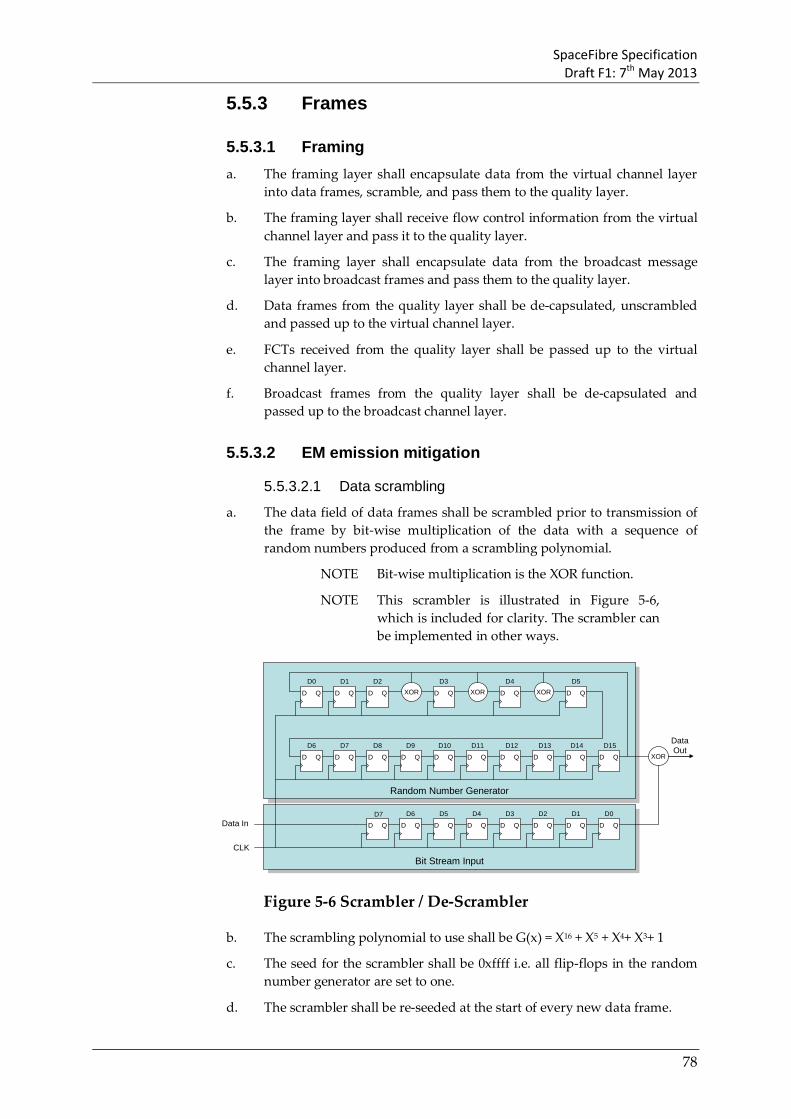
SpaceFibre Specification Draft F1: 7th May 2013
78
5.5.3 Frames
5.5.3.1 Framing a. The framing layer shall encapsulate data from the virtual channel layer
into data frames, scramble, and pass them to the quality layer.
b. The framing layer shall receive flow control information from the virtual channel layer and pass it to the quality layer.
c. The framing layer shall encapsulate data from the broadcast message layer into broadcast frames and pass them to the quality layer.
d. Data frames from the quality layer shall be de-capsulated, unscrambled and passed up to the virtual channel layer.
e. FCTs received from the quality layer shall be passed up to the virtual channel layer.
f. Broadcast frames from the quality layer shall be de-capsulated and passed up to the broadcast channel layer.
5.5.3.2 EM emission mitigation
5.5.3.2.1 Data scrambling
a. The data field of data frames shall be scrambled prior to transmission of the frame by bit-wise multiplication of the data with a sequence of random numbers produced from a scrambling polynomial.
NOTE Bit-wise multiplication is the XOR function.
NOTE This scrambler is illustrated in Figure 5-6, which is included for clarity. The scrambler can be implemented in other ways.
Random Number GeneratorRandom Number Generator
Bit Stream InputBit Stream Input
D Q D Q D Q D Q D Q
D Q D Q D Q D Q D Q D Q D Q D Q
D Q D Q D Q D Q D Q D Q D Q D Q
D Q
D Q D Q
XOR XOR XOR
XOR
Data In
CLK
D7 D6 D4D5 D3 D2 D1 D0
D9 D11D10 D12 D13 D14 D15D6 D8D7
D3 D4 D5D0 D2D1
DataOut
Figure 5-6 Scrambler / De-Scrambler
b. The scrambling polynomial to use shall be G(x) = X16 + X5 + X4+ X3+ 1
c. The seed for the scrambler shall be 0xffff i.e. all flip-flops in the random number generator are set to one.
d. The scrambler shall be re-seeded at the start of every new data frame.

SpaceFibre Specification Draft F1: 7th May 2013
79
e. The single bit output sequence from the random number generator shall be XORed with the bit sequence from the data word.
f. The least-significant bit of the least-significant character in each word shall be scrambled first.
g. When an EOP or EEP or Fill occurs in the data it shall not be replaced by scrambled data but the scrambler shall continue to generate random numbers normally using the value of the 8-bit character associated with the EOP, EEP, or Fill K-Code.
NOTE If the EOP or EEP or Fill control code was replaced by scrambled data it would not be possible to distinguish it from a data value.
5.5.3.2.2 Data Unscrambling
a. When data frames are received they shall be unscrambled by multiplying (XORing) the received data with the same scrambling sequence as was used for scrambling.
b. The control codes representing EOP or EEP shall not be unscrambled.
5.5.3.2.3 Idle frame scrambling
a. The PRBS field of idle frames shall be filled with a pseudo-random bit sequence produced from a pseudo-random bit sequence generation polynomial.
b. The pseudo-random bit sequence generation polynomial to use shall be G(x) = X16 + X5 + X4+ X3+ 1.
c. On cold reset and warm reset the initial seed for the PRBS generator shall be 0xffff, i.e. all flip-flops in the random number generator set to one.
d. The initial seed value shall form the SEED field in the first idle frame sent after cold or warm reset.
e. The single bit output sequence from the random number generator shall form the PRBS in the idle frame.
f. The least-significant bit of the least-significant character in each word shall be filled with PRBS first.
g. At the end of an idle frame the current seed, i.e. value contained in the flip-flops in the random number generator, shall be retained and used to form the seed value of the next idle frame to be sent.
h. The next idle frame shall have its SEED field filled with the retained seed value from the random number generator.
i. The random number generator shall be set to the retained seed value and used to generate the random number to be placed in the PRBS field of the next idle frame.
NOTE In this way a long PRBS results spread over many idle frames. This PRBS sequence spreads the EM emission spectrum from the idle frames. It can also be used to help measure receiver eye

SpaceFibre Specification Draft F1: 7th May 2013
80
patterns when the lane is idle and just sending idle frames.
NOTE Having the seed in each idle frame allows the idle frame contents to be validated if required.
5.5.3.3 Frame reception a. Data frames that are received without error and in the correct order shall
be passed from the quality layer to the framing layer.
b. FCTs received without error and in the correct order shall be passed from the quality layer to the framing layer.
c. Broadcast frames that are received without error and in the correct order shall be passed from the quality layer to the framing layer.
5.5.4 Retry
5.5.4.1 Data words identification state machine a. The Data Word Identification state machine shall be used to identify
which type of frame a data word belongs to, in order to support de-multiplexing of different frame types.
NOTE The state diagram for the Data Word Identification state machine is illustrated in Figure 5-7.

SpaceFibre Specification Draft F1: 7th May 2013
81
RxIdleFrame
SIF
RxDataFrame
RxBroadcast&DataFrame
RxNothingRxBroadcast
Frame
SBFSBF SDF
SDF
EDF
EBF
EBF
SBF
Cold Reset ORRemote Flush OR
Warm ResetSDF ORSBF ORSIF OR
EDF
SDF ORSIF OR
EBF
SDF ORSBF ORSIF OR
EDF
Frame ErrorRX_ERR ORRETRY OR
CRC Error OR Sequence Error OR
Frame Error
Frame Error
Frame Error
EDF OREBF
Frame Error
Figure 5-7 Data Word Identification State Machine
5.5.4.1.2 RxNothing state
a. The RxNothing state shall be entered on one of the following conditions:
1. Following a cold reset, warm reset or remote flush indication.
2. From the RxDataFrame state, when an EDF is received.
3. From the RxBroadcastFrame state, when an EBF is received.
4. From any state when a RX_ERROR, a RETRY, a sequence error, a CRC error or an unexpected control word (Frame Error) is received.
NOTE A sequence error occurs when the Sequence Count in a SEQ_NUM of a data frame, FCT or broadcast frame is not one more (using modulo 128) than the value in the Receive Sequence Counter or the polarity flag is different. It also occurs when the Sequence Number of an idle frame or a FULL word does not match the value of the Receive Sequence Number.
b. When in the RxNothing state the Data Word Identification state machine shall initiate the following actions:
1. Indicate that no frame data is being received.

SpaceFibre Specification Draft F1: 7th May 2013
82
2. Discard any EBF and EDF that are received.
c. The Data Word Identification state machine shall leave the RxNothing State on one of the following conditions, which shall be evaluated in the order given:
1. When an SBF is received, move to the RxBroadcastFrame state.
2. When an SDF is received, move to the RxDataFrame state.
3. When an SIF is received, move to the RxIdleFrame state.
NOTE No action is taken in the RxNothing state when an EDF or EBF is received.
d. The RxNothing state is summarised in Table 5-19.
Table 5-19 RxNothing State
State RxNothing
Entry Following a cold reset or warm reset or remote flush
From the RxDataFrame state, when an EDF is received.
From the RxBroadcastFrame state, when an EBF is received.
From any state when a RX_ERROR, a RETRY, a sequence error a CRC error or an unexpected control word (Frame Error) is received.
Action Indicate that no frame data is being received.
Exit When an SBF is received, move to the RxBroadcastFrame state.
When an SDF is received, move to the RxDataFrame state.
When an SIF is received, move to the RxIdleFrame state.
5.5.4.1.3 RxDataFrame state
a. The RxDataFrame state shall be entered on one of the following conditions:
1. From the RxNothing state, when an SDF is received.
2. From the RxIdleFrame state, when an SDF is received.
3. From the RxBroadcast&DataFrame state, when an EBF is received.
b. When in the RxDataFrame state the Data Word Identification state machine shall initiate the following actions:
1. Indicate that data words being received belong to a data frame.
c. The Data Word Identification state machine shall leave the RxDataFrame state on one of the following conditions, which shall be evaluated in the order given:
1. When an RETRY is received, move to the RxNothing state.
2. When an RXERR is received, move to the RxNothing state.
3. When a CRC error is detected, move to the RxNothing state.

SpaceFibre Specification Draft F1: 7th May 2013
83
4. When a sequence error is detected, move to the RxNothing state.
5. When an SBF is received move to the RxBroadcast&DataFrame state.
6. When an EDF is received, move to the RxNothing state.
7. When an SDF, SIF or EBF is received (Frame Error) move to the RxNothing state.
d. The RxDataFrame state is summarised in Table 5-20.
Table 5-20 RxDataFrame State
State RxDataFrame
Entry From the RxNothing state, when an SDF is received.
From the RxIdleFrame state, when an SDF is received.
From the RxBroadcast&DataFrame state, when an EBF is received.
Action Indicate that data words being received belong to a data frame.
Exit When an RETRY is received, move to the RxNothing state.
When an RXERR is received, move to the RxNothing state.
When a CRC error is detected, move to the RxNothing state.
When a sequence error is detected, move to the RxNothing state.
When an SBF is received move, to the RxBroadcast&DataFrame state.
When an EDF is received, move to the RxNothing state.
When an SDF, SIF or EBF is received (Frame Error) move to the RxNothing state.
5.5.4.1.4 RxBroadcastFrame state
a. The RxBroadcastFrame state shall be entered on one of the following conditions:
1. From the RxNothing state, when an SBF is received.
2. From the RxIdleFrame state, when an SBF is received.
b. When in the RxBroadcastFrame state the Data Word Identification state machine shall initiate the following actions:
1. Indicate that data words being received belong to a broadcast frame.
2. Count the number of data words being received.
c. The Data Word Identification state machine shall leave the RxBroadcastFrame state on one of the following conditions, which shall be evaluated in the order given:
1. When an RETRY is received, move to the RxNothing state.

SpaceFibre Specification Draft F1: 7th May 2013
84
2. When an RXERR is received, move to the RxNothing state.
3. When a CRC error is detected, move to the RxNothing state.
4. When a sequence error is detected, move to the RxNothing state.
5. When an EBF is received, move to the RxNothing state.
6. When an SDF, SBF, SIF or EDF is received (Frame Error) move to the RxNothing state.
d. The RxBroadcastFrame state is summarised in Table 5-21.
Table 5-21 RxBroadcastFrame State
State RxBroadcastFrame
Entry From the RxNothing state, when an SBF is received.
From the RxIdleFrame state, when an SBF is received.
Action Indicate that data words being received belong to a broadcast frame.
Count the number of data words being received.
Exit When an RETRY is received, move to the RxNothing state.
When an RXERR is received, move to the RxNothing state.
When a CRC error is detected, move to the RxNothing state.
When a sequence error is detected, move to the RxNothing state.
When an EBF is received, move to the RxNothing state.
When an SDF, SBF, SIF or EDF is received (Frame Error) move to the RxNothing state.
5.5.4.1.5 RxBroadcast&DataFrame state
a. The RxBroadcast&DataFrame state shall be entered on the following condition:
1. From the RxDataFrame state, when an SBF is received.
b. When in the RxNothing state the Data Word Identification state machine shall initiate the following actions:
1. Indicate that data words being received belong to a broadcast frame.
2. Count the number of data words being received.
c. The Data Word Identification state machine shall leave the RxBroadcast&DataFrame state on one of the following conditions, which shall be evaluated in the order give:
1. When an RETRY is received, move to the RxNothing state.
2. When an RXERR is received, move to the RxNothing state.

SpaceFibre Specification Draft F1: 7th May 2013
85
3. When a CRC error is detected, move to the RxNothing state.
4. When a sequence error is detected, move to the RxNothing state.
5. When an EBF is received and the data word counter is equal to two, move to the RxDataFrame state.
6. When an EBF is received and the data word counter is not equal to two, move to the RxNothing state.
7. When an SDF, SBF, SIF or EDF is received (Frame Error) move to the RxNothing state.
d. The RxBroadcast&DataFrame state is summarised in Table 5-22.
Table 5-22 RxBroadcast&DataFrame State
State RxBroadcast&DataFrame
Entry From the RxDataFrame state, when an SBF is received.
Action Indicate that data words being received belong to a broadcast frame.
Exit When an RETRY is received, move to the RxNothing state.
When an RXERR is received, move to the RxNothing state.
When a CRC error is detected, move to the RxNothing state.
When a sequence error is detected, move to the RxNothing state.
When an EBF is received and the data word counter is equal to two, move to the RxDataFrame state.
When an EBF is received and the data word counter is not equal to two, move to the RxNothing state.
When an SDF, SBF, SIF or EDF is received (Frame Error) move to the RxNothing state.
5.5.4.1.6 RxIdleFrame state
a. The RxIdleFrame state shall be entered on one of the following conditions:
1. From the RxNothing state, when an SIF is received.
b. When in the RxIdleFrame state the Data Word Identification state machine shall initiate the following actions:
1. Indicate that data words being received belong to an idle frame.
c. The Data Word Identification state machine shall leave the RxIdleFrame state on one of the following conditions, which shall be evaluated in the order give:
1. When an RETRY is received, move to the RxNothing state.
2. When an RXERR is received, move to the RxNothing state.
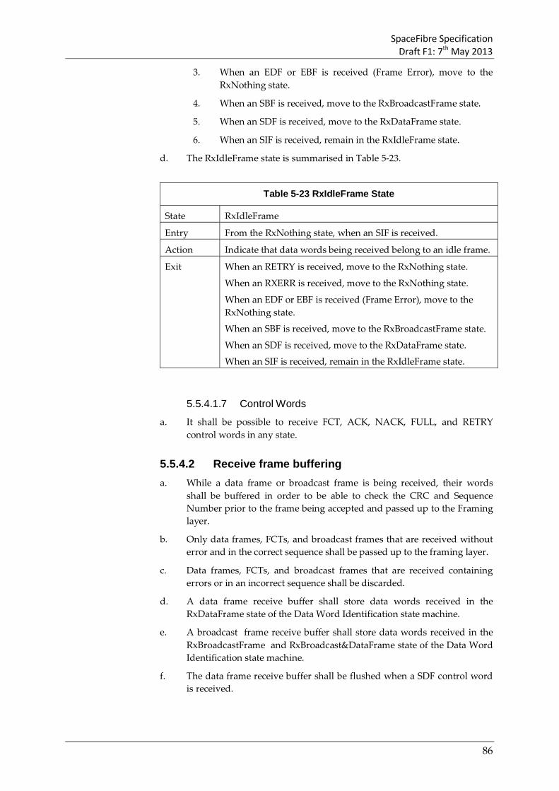
SpaceFibre Specification Draft F1: 7th May 2013
86
3. When an EDF or EBF is received (Frame Error), move to the RxNothing state.
4. When an SBF is received, move to the RxBroadcastFrame state.
5. When an SDF is received, move to the RxDataFrame state.
6. When an SIF is received, remain in the RxIdleFrame state.
d. The RxIdleFrame state is summarised in Table 5-23.
Table 5-23 RxIdleFrame State
State RxIdleFrame
Entry From the RxNothing state, when an SIF is received.
Action Indicate that data words being received belong to an idle frame.
Exit When an RETRY is received, move to the RxNothing state.
When an RXERR is received, move to the RxNothing state.
When an EDF or EBF is received (Frame Error), move to the RxNothing state.
When an SBF is received, move to the RxBroadcastFrame state.
When an SDF is received, move to the RxDataFrame state.
When an SIF is received, remain in the RxIdleFrame state.
5.5.4.1.7 Control Words
a. It shall be possible to receive FCT, ACK, NACK, FULL, and RETRY control words in any state.
5.5.4.2 Receive frame buffering a. While a data frame or broadcast frame is being received, their words
shall be buffered in order to be able to check the CRC and Sequence Number prior to the frame being accepted and passed up to the Framing layer.
b. Only data frames, FCTs, and broadcast frames that are received without error and in the correct sequence shall be passed up to the framing layer.
c. Data frames, FCTs, and broadcast frames that are received containing errors or in an incorrect sequence shall be discarded.
d. A data frame receive buffer shall store data words received in the RxDataFrame state of the Data Word Identification state machine.
e. A broadcast frame receive buffer shall store data words received in the RxBroadcastFrame and RxBroadcast&DataFrame state of the Data Word Identification state machine.
f. The data frame receive buffer shall be flushed when a SDF control word is received.

SpaceFibre Specification Draft F1: 7th May 2013
87
g. The broadcast frame receive buffer shall be flushed when a SBF control word is received.
h. The data and broadcast frame receive buffers shall be flushed when the Data Word Identification state machine enters the RxNothing state.
i. A data frame shall be passed up to the framing layer for de-framing when an EDF is received without errors.
j. A broadcast frame shall be passed up to the framing layer for de-framing when an EBF is received without errors and the broadcast frame contains two data words.
k. When a cold reset, warm reset or remote flush is requested the data frame receive buffer and broadcast frame receive buffer, shall be emptied.
5.5.4.3 CRC for data frame a. A 16-bit CRC checksum shall be applied to data frames.
b. The CRC shall cover an entire data frame, from and including the comma in the start of data frame control word, up to and including the Sequence Number in the end of data frame control word.
c. When a control code is to be included in the CRC calculation, its data value shall be used.
NOTE For example, K28.7 the comma code is replaced by D28.7 in the CRC calculation.
d. When an EOP or EEP or Fill occurs in the data the value of the control code representing the EOP or EEP or Fill shall be included in the CRC generation.
NOTE For example, an EOP is represented by K29.7 so the value D29.7 would be included in the CRC calculation. Including an EOP or EEP or Fill in the CRC calculation means that they are protected by the CRC checksum.
e. The 16-bit CRC calculation shall be the CRC-16-CCITT.
f. The least-significant bit of the least-significant character in each word shall be computed first.
5.5.4.4 CRC for broadcast frame, FCT, ACK and NACK a. 8-bit CRC An 8-bit CRC checksum shall be applied to broadcast frames,
FCTs, FULLs, ACKs and NACKs.
b. The 8-bit CRC shall cover an entire broadcast frame, from and including the comma in the start of broadcast frame control word, up to and including the Sequence Number in the end of broadcast frame control word.
c. When a control code is to be included in the CRC calculation, its data value shall be used.

SpaceFibre Specification Draft F1: 7th May 2013
88
NOTE For example, K28.7 the comma code is replaced by D28.7 in the CRC calculation.
d. The 8-bit CRC calculation procedures shall:
1. use modulo 2 arithmetic for polynomial coefficients;
2. use a systematic binary (n+16,n) block code, where (n+8) is the number of bits of the codeword ( )c x and n is divisible by 8; n is the number of bits covered by the CRC;
3. use the following generating polynomial: 8 2( ) 1g x x x x= + + +
4. use byte format as input and output, for which the bits are represented as:
7 6 5 4 3 2 1 0b b b b b b b b
where 7b is the most significant bit and 0b is the least significant bit;
e. The 8-bit CRC generation procedure shall behave as follows:
1. The procedure accepts an n-bit input which is used to construct ( )m x , where:
(a) the n-bit input is defined to be the set of bits ,i jB grouped
into / 8n bytes where { }0,1, , / 8 1i n= − is the byte
index and { }7,6, ,0j = is the bit index;
(b) the / 8n input bytes correspond to the fields covered by the CRC excluding the CRC byte; the first byte transmitted has index 0i = ; the last byte transmitted has index / 8 1i n= − ;
(c) ( )m x is a polynomial 00
22
11 ... xmxmxm n
nn
n +++ −−
−−
having binary coefficients im ;
(d) ( )m x can be represented as an n-bit vector where coefficient
1nm − of the highest power of x is the most significant bit
and coefficient 0m of the lowest power of x is the least significant bit;
(e) the bit vector representation of ( )m x is formed by concatenating the / 8n bytes of the input in transmission order, where the least significant bit 0b of each byte is taken
first and the most significant bit 7b of each byte is taken last:
1 0,0 2 0,1 3 0,2 7 0,6 8 0,7, , , , , ,n n n n nm B m B m B m B m B− − − − −= = = = =
9 1,0 10 1,1 11 1,2 15 1,6 16 1,7, , , , , ,n n n n nm B m B m B m B m B− − − − −= = = = =
7 /8 1,0 6 /8 1,1 5 /8 1,2 1 /8 1,6 0 /8 1,7, , , , ,n n n n nm B m B m B m B m B− − − − −= = = = =

SpaceFibre Specification Draft F1: 7th May 2013
89
2. The procedure generates the remainder polynomial ( )r x given by the equation:
8( ) ( ) modulo ( )r x m x x g x = ⋅
where 7 6 07 6 0( )r x r x r x r x= + + and ir are binary coefficients;
3. The Header and Data CRC are formed from the 8-bit vector representation of ( )r x ; the least significant bit 0b of the CRC byte
is coefficient 7r of the highest power of x , while the most
significant bit 7b of the CRC byte is coefficient 0r of the lowest power of x :
7 0 6 1 5 2 4 3 3 4 2 5 1 6 0 7, , , , , , ,b r b r b r b r b r b r b r b r= = = = = = = =
NOTE 1 The codeword 8( ) ( ) ( )c x m x x r x= ⋅ + is formed by concatenating the bit vector representations of
( )m x and ( )r x .
NOTE 2 When a Galois version of a Linear Feedback Shift Register is used for CRC generation, its initial value is zero.
NOTE 3 Example VHDL and C-code implementations of this CRC algorithm are included in clause Annex B.
f. If the CRC generation procedure is applied to the bytes covered by the CRC excluding the CRC byte then the generated CRC shall be compared directly with the expected CRC byte. If the generated and expected CRC bytes are equal then no errors have been detected; if they are different then an error has been detected.
g. If the CRC generation procedure is applied to the bytes covered by the CRC including the CRC byte then the output of the CRC generation procedure shall be zero if no errors have been detected and non-zero if an error has been detected.
NOTE 1 When the codeword *( )c x is input to the CRC generator then the remainder is the syndrome:
* 8( ) ( ) modulo ( )s x c x x g x = ⋅ .
NOTE 2 The codeword *( )c x is the concatenation of the Header or Data bytes covered by the CRC, followed by the CRC byte.
5.5.4.5 Sequence Numbering
5.5.4.5.1 Sequence Numbers on transmission
a. A single 7-bit Transmit Sequence Counter shall be maintained in the transmit side of the SpaceFibre CODEC to hold the 7-bit Sequence Count in the SEQ_NUM of the last data frame, broadcast frame or FCT control word that was sent.
b. The 7-bit Transmit Sequence Counter shall operate modulo 128.

SpaceFibre Specification Draft F1: 7th May 2013
90
c. A Transmit Polarity Flag shall be associated with the 7-bit Transmit Sequence Counter together forming the Sequence Number (SEQ_NUM), see section 5.3.1.4.2.
d. The Transmit Sequence Counter shall be cleared to zero on cold reset of the SpaceFibre CODEC.
e. The Transmit Polarity Flag shall be cleared to zero on cold reset of the SpaceFibre CODEC.
f. The Transmit Sequence Counter shall be cleared to zero on remote flush indication.
g. The Transmit Polarity Flag shall be cleared to zero on remote flush indication.
h. The Transmit Sequence Counter shall not be modified on warm reset of the SpaceFibre CODEC.
i. The Transmit Polarity Flag shall not be modified on warm reset of the SpaceFibre CODEC.
j. The Transmit Polarity Flag shall be inverted each time a new retry operation begins.
k. The Transmit Sequence Counter and associated polarity flag shall provide Sequence Numbers for data frames, FCTs, broadcast frames, idle frames and FULL words.
l. Immediately prior to an end of data frame, end of broadcast frame, or FCT control word being passed from the quality layer to the lane layer, the current value of the Transmit Sequence Counter shall be incremented and the new value together with the current value of the polarity flag placed in the Sequence Number (SEQ_NUM) field of the end of data frame, end of broadcast frame, or FCT control word.
NOTE Every 128 sequence numbers the counter will roll over repeating the series of sequence numbers.
m. When an idle frame is passed from the quality layer to the lane layer, the current value of the Transmit Sequence Counter together with the current value of the polarity flag shall be placed in the Sequence Number (SEQ_NUM) field of the start of idle frame (SIF) control word.
5.5.4.5.2 Sequence Numbers on reception
a. A single 7-bit Receive Sequence Counter shall be maintained in the receive side of the SpaceFibre CODEC to hold the 7-bit Sequence Count in the SEQ_NUM of the last data frame, broadcast frame or FCT control word that was received correctly.
b. The 7-bit Receive Sequence Counter shall operate modulo 128.
c. A Receive Polarity Flag shall be associated with the 7-bit Receive Sequence Counter together called the Receive Sequence Number, the value of which is checked against received Sequence Numbers (SEQ_NUM).

SpaceFibre Specification Draft F1: 7th May 2013
91
d. The Receive Polarity Flag shall be determined by the Receive Error State Machine.
e. The Receive Sequence Counter shall be cleared to zero on cold reset of the SpaceFibre CODEC.
f. The Receive Polarity Flag shall be cleared to zero on cold reset of the SpaceFibre CODEC.
g. The Receive Sequence Counter shall be cleared to zero on remote flush indication.
h. The Receive Polarity Flag shall be cleared to zero on remote flush indication.
i. The Receive Sequence Counter shall not be modified on warm reset of the SpaceFibre CODEC.
j. The Receive Polarity Flag shall not be modified on warm reset of the SpaceFibre CODEC.
k. The 7-bit Receive Sequence Counter together with the Receive Polarity Flag shall be used to check the sequence numbers of data frames, FCTs broadcast frames, idle frames and FULL control words.
l. When an EDF, EBF, SIF, FCT, or FULL control word with a valid CRC passes into the quality layer from the multi-lane layer, its Sequence Number (SEQ_NUM) shall be checked against the current value of the Receive Sequence Counter and Receive Polarity Flag.
m. If the Sequence Count of the SEQ_NUM of a received EDF, EBF or FCT is one more than the Receive Sequence Counter and the polarity flag of the SEQ_NUM matches the Receive Polarity Flag, the data frame, broadcast frame or FCT shall be accepted.
NOTE A sequence error occurs when the Sequence Count in a SEQ_NUM of a data frame, broadcast frame or FCT is not one more (using modulo 128) than the value in the Receive Sequence Counter or the polarity flag is different. It also occurs when the Sequence Number of an idle frame or FULL control word does not match the value of the Receive Sequence Number.
n. If the Sequence Number (SEQ_NUM) of a received SIF or FULL has the same value as the Receive Sequence Number the idle frame shall be accepted.
NOTE An idle or FULL frame carries the Sequence Number of the last data frame, broadcast frame or FCT transmitted.
o. When a data frame, FCT or broadcast frame is accepted, the Receive Sequence Counter shall be incremented.
p. If the Sequence Number (SEQ_NUM) of a received EDF, EBF or FCT is not one more than the Receive Sequence Counter, the data frame, FCT or broadcast frame shall be rejected.
SpaceFibre Specification Draft F1: 7th May 2013
92
q. When a data frame, FCT or broadcast frame is rejected, the Receive Sequence Counter shall not be incremented.
r. If the polarity flags of the received SEQ_NUM and the local receive sequence counter do not match, the data frame, FCT, broadcast or idle frame shall be rejected.
NOTE See section 5.5.4.9 more information about the value of the polarity flag of the Receive Sequence Number.
5.5.4.6 Frame retry buffering a. Data frames, FCTs and broadcast frames shall be placed in dedicated
frame retry buffers, as they pass from the frame layer to the quality layer, and are sent over the SpaceFibre link.
NOTE The retry buffers are not intermediate buffers: they only contain frames/FCTs that have been sent over the SpaceFibre link.
NOTE The total number of frames or FCT words that can be stored in the frame retry buffers after they are sent is less than 128, because of the size of SEQ_NUM.
b. The data frames, FCTs, and broadcast frames in the retry buffers shall be referenced by the Sequence Number (SEQ_NUM) given to them when they are sent over the SpaceFibre link.
c. When an ACK is received, all data frames, FCTs and broadcast frames, sent with a Sequence Count less than or equal to the Sequence Count in the ACK shall be deleted from the frame retry buffers, taking into account counter roll over effects (i.e. calculation is modulo 128).
d. A NACK received with the polarity flag in the Sequence Number (SEQ_NUM) which is different to the Transmit Polarity Flag shall be ignored and not cause a retry.
NOTE This prevents an error from causing multiple retries.
e. When a NACK is received with a valid CRC and with a polarity flag in the Sequence Number field equal to the Transmit Polarity Flag, the NACK shall be accepted.
f. When a NACK is accepted, all the data frames, FCTs, and broadcast frames with a Sequence Count less than or equal to that of the NACK shall be removed from the frame retry buffer, since the NACK has signalled that they have been received correctly.
g. When a NACK is accepted, the data frame, FCT or broadcast frame, which has a Sequence Count one more than that of the NACK shall be resent together with all data frames, FCTs and broadcast frames which have higher Sequence Count values, since the NACK has signalled that they have not been received correctly.

SpaceFibre Specification Draft F1: 7th May 2013
93
NOTE See section 5.5.4.8.2 for reasons why a NACK is transmitted.
h. When the contents of the retry buffers are resent, the broadcast frames should always be sent before FCT and data frames, even if the broadcast frames were not sent before the NACK was received. The frame precedence detailed in section 5.3.4 shall prevail.
i. When the contents of the retry buffers are resent they shall be given new Sequence Counts following on from the last correctly received Sequence Count plus one and incrementing with each frame/FCT that is retried or otherwise sent.
NOTE The data frames, FCTs, and broadcast frames that are resent have the polarity flag in the FR-SEQ# set to the new polarity value of the Transmit Polarity Flag determined in section 5.5.4.9
j. The number of retries shall be recorded and made available in a status register.
k. On cold reset and remote flush the frame/FCT retry buffers shall be emptied.
l. On a cold reset and remote flush the number of retries shall be cleared to zero.
m. On warm reset the frame/FCT retry buffers shall not be emptied
n. On a warm reset the number of retries shall be cleared.
o. The size of the frame retry buffers shall be implementation dependent.
NOTE The frame retry buffer should be long enough to hold all the data and control words that can fit on the line for as long as it takes to send a frame and receive an ACK in reply.
NOTE When multiple lanes are used proportionally more data can be held on the line.
p. When a retry buffer becomes full, no more data for this buffer shall be accepted from the framing layer.
q. When one or more of the retry buffers is full, FULL control words shall be sent following the precedence detailed in section 5.3.4.
r. When a total of 128 frames or FCTs are pending to be acknowledged FULL words shall be sent.
NOTE 128 is the maximum number of frames or FCTs that can be outstanding due to the size of the Sequence Number.
s. When all the frame retry buffers are full, only FULLs, ACKs and NACKs shall be sent by the quality layer.
t. If a broadcast frame is resent during a retry the LATE flag in the RSVD/LATE field of the end of broadcast frame (EBF) shall be set to one, otherwise the LATE flag shall be zero.

SpaceFibre Specification Draft F1: 7th May 2013
94
NOTE The LATE flag set to one indicates that the broadcast frame has been delayed.
5.5.4.7 Idle frames a. Idle frames shall be generated when there are no data frames, FCTs,
broadcast frames or FULLs to send.
b. The Sequence Number field in the start of idle frame shall be set to the current value of the Transmit Sequence Number, including the polarity flag.
NOTE After a cold reset or remote flush this counter is set to zero so if an idle frame is the first frame sent after cold reset, its Sequence Number field will be zero. If a data frame, FCT, or broadcast frame is the first frame sent after a cold reset its Sequence Number field will be one.
c. The start of idle frame control word shall be followed by a series of pseudo-random data words which will form a pseudo random bit sequence when transmitted as described in section 5.5.3.2.3
5.5.4.8 ACK/NACK control
5.5.4.8.1 Sending ACKs
a. When a data frame, broadcast frame, FCT or FULL is received without a sequence error or CRC error, an ACK shall be requested to be sent
b. ACKs shall be sent as soon as possible after being requested, taking into account control word precedence, see section 5.3.4.
NOTE ACKs are not buffered before they are sent
c. After an ACK is sent there shall be a minimum of 15 words before another ACK is sent.
NOTE This ensures that the bandwidth reserved quality of service works independently of the size of data frames.
d. If another data frame, broadcast frame, FCT or FULL is received while an ACK is pending, only one ACK shall be sent.
NOTE An ACK need not be sent for every data frame, broadcast frame, FCT or FULL.
e. When an ACK is sent, it shall contain the current value of the Receive Sequence Counter and the Receive Polarity Flag.
f. When a NACK is requested to be sent, any pending ACK shall be cancelled and not sent.
5.5.4.8.2 Sending NACKs
a. A NACK shall be requested to be sent under any of the following conditions:

SpaceFibre Specification Draft F1: 7th May 2013
95
1. When a RX_ERR control word is received, or a CRC error or a sequence error occurs while the Data Word Initialisation state machine is in the RxDataFrame, RxBroadcastFrame, or RxData&BroadcastFrame states,
2. When the type of frame received cannot be identified or if an unrecognised word is received or if a word is received in an unexpected place in a frame,
3. When a received idle frame or a FULL control word contains a Sequence Number which is not the same as the Receive Sequence Number.
NOTE A NACK requested to be sent means that a NACK will be pending to be sent if it cannot be sent immediately.
NOTE The idle Sequence Number ought to have the same sequence number as the last correctly received data frame, FCT, or broadcast frame i.e. be the same as the current value of the Receive Sequence Counter. If this is not the case it indicates that a frame that has been sent has not been received, so a NACK is sent to indicate the last correctly received data frame, FCT or broadcast frame.
NOTE When an idle frame is received that has the correct Sequence Number there is no need to send an ACK. The correct Sequence Number indicates that the last data frame, FCT or broadcast frame has been received correctly. If the ACK sent for this frame has gone missing, it does not matter unless the frame retry buffer fills up which will not happen unless more data frames, FCTs or broadcast frames are sent. In which case other ACKs will be sent.
b. A NACK requested to be sent shall be sent as soon as possible taking into account control word precedence (see section 5.3.4) and using the polarity flag value determined by the Receive Error State Machine (see section 5.5.4.9).
c. When a NACK is sent it shall contain the current value of the Receive Sequence Counter with the Receive Polarity Flag inverted.
d. When an ACK is requested to be sent, any pending NACK shall be cancelled and not sent.
NOTE A pending NACK is one that has been requested to be sent but was not able to be sent immediately because control or data words with higher precedence were being sent.
5.5.4.8.3 Receiving ACKs
a. When an ACK is received it shall be checked for errors using its CRC.

SpaceFibre Specification Draft F1: 7th May 2013
96
b. An ACK is considered valid when it has a valid CRC and the polarity flag of its Sequence Number has the same value as the Transmit Polarity Flag.
c. When a valid ACK is received, all data frames, broadcast frames, and FCTs sent with a Sequence Count less than or equal to the Sequence Count in the ACK shall be deleted from the frame retry buffer, taking into account counter roll over effects (i.e. calculation is modulo 128).
5.5.4.8.4 Receiving NACKs
a. When a NACK is received it shall be checked for errors using its CRC.
b. A NACK is considered valid when it has a valid CRC and the polarity flag of its Sequence Number has the same value as the Transmit Polarity Flag.
c. When a valid NACK is received the following actions shall be executed in the specified order:
1. All data frames, FCTs and broadcast frames, sent with a Sequence Count less than or equal to the Sequence Count in the NACK shall be deleted from the frame retry buffers, taking into account counter roll over effects (i.e. calculation is modulo 128).
2. The Transmit Sequence Counter is set to the value of the NACK sequence Count.
3. The polarity flag of the Transmit Sequence Number shall be inverted.
4. Any record of the sequences numbers sent related to the content of the retry buffers shall be cleared.
NOTE When the frames/FCTs are resent they will be given new sequence numbers.
5. A RETRY word shall be sent before the contents of the retry buffer are sent
6. The contents of the retry buffers shall be sent following the precedence indicated in section 5.3.4.
5.5.4.9 Receive Error State Machine a. The Receive Error State Machine shall be used to determine the state of
the Receive Polarity Flag field of the Receive Sequence Number.
NOTE The state diagram for the Receive Error State Machine is illustrated in Figure 5-8

SpaceFibre Specification Draft F1: 7th May 2013
97
Valid Positive(ACKs sent are
positive)
NACK requested to be sent
Valid Negative(ACKs sent are
negative)
Error Positive(NACKs sent are
negative)
Error Negative(NACKs sent are
positive)
ACK requested to be sent
Invalid frame sequence number received with positive polarity
Invalid frame sequence number received with negative polarity
ACK requested to be sent
Cold ResetWarm Reset
Remote Flush
NACK requested to be sent
Figure 5-8 Receive Error State Machine
5.5.4.9.2 Valid Positive State
a. The Valid Positive state shall be entered on the following conditions:
1. ColdReset command.
2. WarmReset command.
3. Remote Flush.
4. From the Error Positive state, when an ACK is requested to be sent.
b. When in the Valid Positive state the Receive Polarity Flag shall be positive.
NOTE ACKs will therefore be sent with a positive Sequence Number.
c. The Receive Error State Machine shall leave the Valid Positive state on the following conditions:
1. When a NACK is requested to be sent, move to the Error Negative state, before sending the NACK.
NOTE Note the NACK will therefore be sent with a positive Sequence Number, because NACKs are sent with the opposite polarity of that indicated by the Receive Error State Machine.
NOTE The Valid Positive state is summarised in Table 5-24.

SpaceFibre Specification Draft F1: 7th May 2013
98
Table 5-24 Valid Positive State
State Valid Positive
Entry ColdReset command.
WarmReset command.
Remote Flush.
From the Error Positive state, when an ACK is requested to be sent.
Action The Receive Polarity Flag shall be positive and ACKs sent with a positive Sequence Number.
Exit When a NACK is requested to be sent, move to the Error Negative state, before sending the NACK with a positive Sequence Number.
5.5.4.9.3 Valid Negative State
a. The Valid Negative state shall be entered on the following conditions:
1. From the Error Negative state, when an ACK is requested to be sent.
b. When in the Valid Negative state the Receive Polarity Flag shall be negative.
NOTE ACKs will therefore be sent with a negative Sequence Number.
c. The Receive Error State Machine shall leave the Valid Negative state on the following conditions:
1. When a NACK is requested to be sent, move to the Error Positive state, before sending the NACK.
NOTE Note the NACK will therefore be sent with a negative Sequence Number.
NOTE The Valid Negative state is summarised in Table 5-25.
Table 5-25 Valid Negative State
State Valid Negative
Entry From the Error Negative state, when an ACK is requested to be sent.
Action The Receive Polarity Flag shall be negative and ACKs send with a negative Sequence Number.
Exit When a NACK is requested to be sent, move to the Error Positive state, before sending the NACK with a negative Sequence Number.
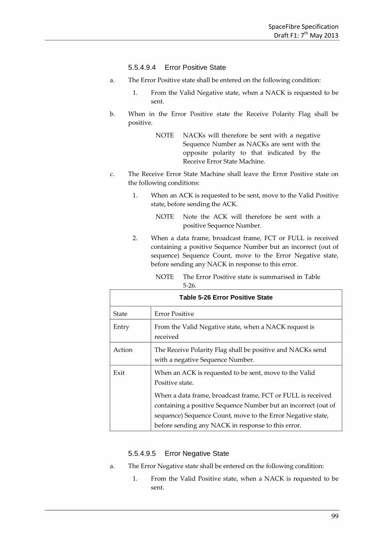
SpaceFibre Specification Draft F1: 7th May 2013
99
5.5.4.9.4 Error Positive State
a. The Error Positive state shall be entered on the following condition:
1. From the Valid Negative state, when a NACK is requested to be sent.
b. When in the Error Positive state the Receive Polarity Flag shall be positive.
NOTE NACKs will therefore be sent with a negative Sequence Number as NACKs are sent with the opposite polarity to that indicated by the Receive Error State Machine.
c. The Receive Error State Machine shall leave the Error Positive state on the following conditions:
1. When an ACK is requested to be sent, move to the Valid Positive state, before sending the ACK.
NOTE Note the ACK will therefore be sent with a positive Sequence Number.
2. When a data frame, broadcast frame, FCT or FULL is received containing a positive Sequence Number but an incorrect (out of sequence) Sequence Count, move to the Error Negative state, before sending any NACK in response to this error.
NOTE The Error Positive state is summarised in Table 5-26.
Table 5-26 Error Positive State
State Error Positive
Entry From the Valid Negative state, when a NACK request is received
Action The Receive Polarity Flag shall be positive and NACKs send with a negative Sequence Number.
Exit When an ACK is requested to be sent, move to the Valid Positive state.
When a data frame, broadcast frame, FCT or FULL is received containing a positive Sequence Number but an incorrect (out of sequence) Sequence Count, move to the Error Negative state, before sending any NACK in response to this error.
5.5.4.9.5 Error Negative State
a. The Error Negative state shall be entered on the following condition:
1. From the Valid Positive state, when a NACK is requested to be sent.

SpaceFibre Specification Draft F1: 7th May 2013
100
b. When in the Error Negative state the Receive Polarity Flag shall be negative.
NOTE NACKs will therefore be sent with a positive Sequence Number.
c. The Receive Error State Machine shall leave the Error Negative state on the following conditions:
1. When an ACK is requested to be sent, move to the Valid Negative state, before sending the ACK.
NOTE Note the ACK will therefore be sent with a negative Sequence Number.
2. When a data frame, broadcast frame, FCT or FULL is received containing a negative Sequence Number but an incorrect (out of sequence) Sequence Count, move to the Error Positive state, before sending any NACK in response to this error.
NOTE The Error Negative state is summarised in Table 5-27.
Table 5-27 Error Negative State
State Error Negative
Entry From the Valid Positive state, when a NACK request is received
Action The Receive Polarity Flag shall be negative and NACKs send with a positive Sequence Number.
Exit When an ACK is requested to be sent, move to the Valid Negative state.
When a data frame, broadcast frame, FCT or FULL is received containing a negative Sequence Number but an incorrect (out of sequence) Sequence Count, move to the Error Positive state, before sending any NACK in response to this error.
5.6 Multi-lane layer In this section the Multi-Lane Layer of SpaceFibre is specified.
5.6.1 Multi-lane control a. The Required Number of Lanes management parameter (required lanes)
shall specify the number of lanes that are to be used to form the SpaceFibre link.
b. The number of lanes that are active and ready to send data and control words (active lanes) shall be indicated from the lane layer to the multi-lane layer.
SpaceFibre Specification Draft F1: 7th May 2013
101
c. If the number of required lanes is less than the number of active lanes, the number of used lanes shall be set to the number of required lanes.
d. If the number of required lanes is the same as the number of active lanes, the number of used lanes shall be set to the number of required lanes.
e. If the number of required lanes is more than the number of active lanes, the number of used lanes shall be set to the number of active lanes.
f. Each lane shall be given a lane number, starting at 1 and incrementing for each physical link.
NOTE For example, if there are four possible lanes they would be given lane numbers 1, 2, 3 and 4.
5.6.2 Multi-lane synchronisation a. When the number of required lanes or the number of active lanes
changes, lane synchronisation shall occur.
b. During lane synchronisation the number of used lanes shall be determined.
c. Lanes shall be assigned lane umbers as follows: the lowest number lane that is active is assigned lane number 1, the next lowest number lane that is active is assigned lane number 2, and subsequent lanes are assigned lane numbers in this way until enough lanes have been assigned lane numbers to cover the number of used lanes.
d. All other physical links that are active shall be assigned a null lane number (zero).
e. An LSYNC control word shall be sent over each of the active lanes containing the lane number assigned to that lane.
f. The LSYNC control word shall be sent over each of the active lanes at approximately the same time, i.e. within the time it takes to transmit one control word (TBC).
g. Once the LSYNC control word has been sent, data and control words can be distributed over the used lanes for transmission.
h. When an LSYNC control word is received, the lane synchroniser shall wait for LSYNC control words to be received over each of the other active lanes.
i. When LSYNC control words have been received on all active lanes, the lane concentrator shall be updated with the lanes it is to concentrate data from.
j. The active lanes that receive an LSYNC control word containing a null (zero) shall not be included in the lane concentration.
k. The active lanes that receive an LSYNC control word containing a lane number shall be included in the lane concentration.

SpaceFibre Specification Draft F1: 7th May 2013
102
l. If an LSYNC control word is not received on a lane when LSYNC control words are received on the other active lanes, all the lanes are instructed to reinitialise.
NOTE Link re-initialisation will automatically invoke resynchronisation of the lanes.
m. If the received LSYNC control words do not form a proper integer series (i.e. 1, 2, 3, etc) of lane numbers with no duplicate lane numbers, other than possible duplicate null lanes, and no missing lane numbers, all the lanes are instructed to reinitialise.
NOTE This is likely to be because it was lost and replaced by an RXERR control word or the result of a serious error in the transmitter, which re-initialisation might not correct.
n. If after invoking re-initialisation of lanes, lane synchronisation still fails, the error shall be flagged as a permanent error and the user application informed.
5.6.3 Multi-lane distribution a. Data and control words to be sent over the SpaceFibre link shall be
distributed over the used lanes.
b. The first data or control word shall be sent over the lowest number used lane, the next data or control word over the next lowest number used lane, and so on with data or control words being sent over each of the used lanes.
c. Data and control words shall not be sent over active lanes which are not used lanes.
NOTE Such lanes are providing hot standby and will be sending IDLE control words.
5.6.4 Multi-lane concentration a. When a data or control word arrives over a lane, it shall be placed in a
small synchronisation FIFO.
b. There shall be one synchronisation FIFO for each lane.
c. The synchronisation FIFO shall be able to store at least three data or control words.
d. Data or control words shall be read out of the synchronisation FIFOs for each used lane in lane number order.
e. Following lane synchronisation, the first data or control word shall be read out of the lane with the lowest lane number, the next data or control word over the next lowest number used lane, and so on with data and control words being read out of the synchronisation FIFOs of each of the used lanes.

SpaceFibre Specification Draft F1: 7th May 2013
103
NOTE The lane numbers of the concentrator can be different to that of the distributor.
5.6.5 Multi-lane selection It shall be possible to switch off or bypass multi-lane operation so that the SpaceFibre link operates over one lane only.
5.7 Lane layer In this section the Lane Layer of SpaceFibre is specified.
5.7.1 Lane initialisation and standby management a. The Lane Initialisation state machine shall control the initialisation of the
SpaceFibre link: establishing the connection and responding to standby management requests.
NOTE The state diagram for the lane initialisation state machine is illustrated in Figure 5-9.
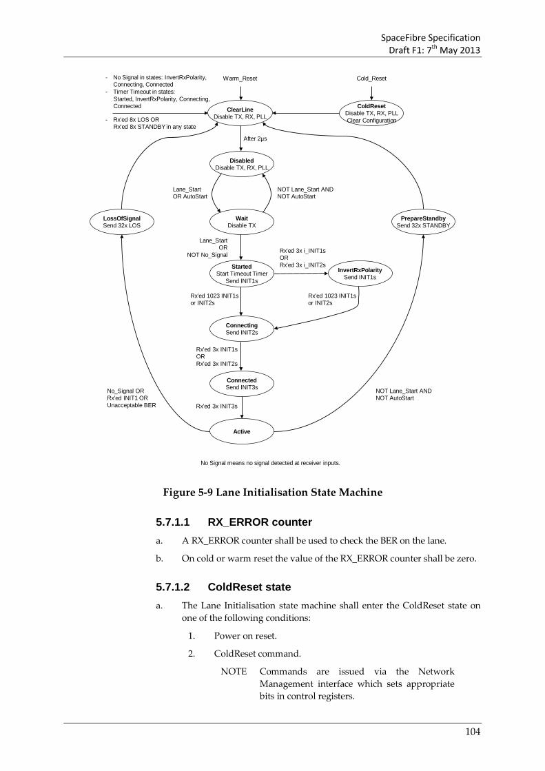
SpaceFibre Specification Draft F1: 7th May 2013
104
WaitDisable TX
ClearLineDisable TX, RX, PLL
InvertRxPolaritySend INIT1s
StartedStart Timeout Timer
Send INIT1s
Warm_Reset
ConnectingSend INIT2s
Cold_Reset
DisabledDisable TX, RX, PLL
After 2μs
No Signal means no signal detected at receiver inputs.
Rx’ed 1023 INIT1sor INIT2s
Lane_StartOR AutoStart
NOT Lane_Start ANDNOT AutoStart
ColdResetDisable TX, RX, PLLClear Configuration
Lane_StartOR
NOT No_SignalRx’ed 3x i_INIT1sOR Rx’ed 3x i_INIT2s
Rx’ed 1023 INIT1sor INIT2s
ConnectedSend INIT3s
Rx’ed 3x INIT1sOR Rx’ed 3x INIT2s
Active
Rx’ed 3x INIT3s
PrepareStandbySend 32x STANDBY
LossOfSignalSend 32x LOS
No_Signal ORRx’ed INIT1 ORUnacceptable BER
NOT Lane_Start ANDNOT AutoStart
- No Signal in states: InvertRxPolarity, Connecting, Connected
- Timer Timeout in states:Started, InvertRxPolarity, Connecting,Connected
- Rx’ed 8x LOS OR Rx’ed 8x STANDBY in any state
Figure 5-9 Lane Initialisation State Machine
5.7.1.1 RX_ERROR counter a. A RX_ERROR counter shall be used to check the BER on the lane.
b. On cold or warm reset the value of the RX_ERROR counter shall be zero.
5.7.1.2 ColdReset state a. The Lane Initialisation state machine shall enter the ColdReset state on
one of the following conditions:
1. Power on reset.
2. ColdReset command.
NOTE Commands are issued via the Network Management interface which sets appropriate bits in control registers.

SpaceFibre Specification Draft F1: 7th May 2013
105
b. When in the ColdReset state the Lane Initialisation state machine shall initiate the following actions:
1. Reset of the SpaceFibre Lane.
2. Reset of all the Lane Configuration registers.
3. Assert the Cold_Reset_Flag.
NOTE This flag is used to indicate that it was a cold reset that caused the re-initialisation.
4. Disable the transmitter driver, receiver and related transmit PLL and receive clock recovery.
NOTE This is to save power.
c. The Lane Initialisation state machine shall leave the ColdReset state on one of the following conditions:
1. Unconditionally, move to the ClearLine state.
d. The ColdReset state is summarised in Table 5-28.
Table 5-28 ColdReset State
State ColdReset
Entry Power on reset.
ColdReset command.
Action Reset of the SpaceFibre Lane.
Reset of all the Lane Configuration registers.
Disable the transmitter driver, receiver and related transmit PLL and receive clock recovery.
Exit Unconditionally, move to the ClearLine state.
5.7.1.3 ClearLine state a. The Lane Initialisation state machine shall enter the ClearLine state on
one of the following conditions:
1. From the ColdReset state, unconditionally.
2. On WarmReset command.
3. From the Started state, when the initialisation timeout timer expires.
NOTE The initialisation timeout timer is started in the Start state and stopped in the Active state. It will timeout if initialisation takes longer than 2 ms. This period allows plenty of time for the receive clock recovery at the far end of the lane to lock onto the transmitted signal, a response to be generated, returned to the near end and the local receiver to lock onto the returned signal.

SpaceFibre Specification Draft F1: 7th May 2013
106
4. From the InvertRxPolarity state, when the initialisation timeout timer expires.
5. From the Connecting state, when the initialisation timeout timer expires.
6. From the Connected state, when the initialisation timeout timer expires.
7. From any state when 8 consecutive LOS words are received.
8. From any state when 8 consecutive STANDBY words are received.
9. From the InvertRxPolarity state, when No Signal is detected at the receiver.
10. From the Connected state, when No Signal is detected at the receiver.
11. From the Connecting state, when No Signal is detected at the receiver.
12. From the PrepareStandby state, after sending 32 STANDBY control words.
13. From the LossOfSignal state, after sending 32 LOST_SIGNAL control words.
b. When in the ClearLine state the Lane Initialisation state machine shall initiate the following actions:
1. Start a 2 μs timeout timer.
2. Disable the transmitter driver, receiver and related transmit PLL and receive clock recovery.
3. Do NOT reset the Lane Configuration registers.
4. Switch off receiver bit inversion.
c. The Lane Initialisation state machine shall leave the ClearLine state on one of the following conditions, which are to be evaluated in the order given:
1. When ColdReset is asserted, move to the ColdReset state.
2. When the 2 μs timeout timer expires, move to the Disabled state.
NOTE This is more than long enough for signals to propagate through the longest permitted fibre optic cable (100m) and back again, and to allow time for the signals to be processed at each end of the cable. The result is that the lanes forming the link will be completely reset at the near end of the link and at least warm reset at the far end.
d. The ClearLine state is summarised in Table 5-29.
Table 5-29 ClearLine State
State ClearLine

SpaceFibre Specification Draft F1: 7th May 2013
107
Entry From the ColdReset state, unconditionally.
On WarmReset command.
From the Started state, when the initialisation timeout timer expires.
From the InvertRxPolarity state, when the initialisation timeout timer expires.
From the Connecting state, when the initialisation timeout timer expires.
From the Connected state, when the initialisation timeout timer expires.
From any state when 8 LOS words are received.
From any state when 8 consecutive STANDBY words are received.
From the InvertRxPolarity state, when No Signal is detected at the receiver.
From the Connected state, when No Signal is detected at the receiver.
From the Connecting state, when No Signal is detected at the receiver
From the PrepareStandby state, after sending 32 STANDBY control words.
From the LossOfSignal state, after sending 32 LOST_SIGNAL control words.
Action Start a 2 μs timeout timer.
Disable the transmitter driver, receiver and related transmit PLL and receive clock recovery.
Do NOT reset the Lane Configuration registers.
Switch off receiver bit inversion.
Exit When ColdReset is asserted, move to the ColdReset state.
When the 2 μs timeout timer expires, move to the Disabled state.
5.7.1.4 Disabled state a. The Lane Initialisation state machine shall enter the Disabled state on the
following condition:
1. From the ClearLine state, after waiting there for 2μs.
b. When in the Disabled state the Lane Initialisation state machine shall initiate the following action:
1. Disable the transmitter driver, receiver and related transmit PLL and receive clock recovery.
c. The Lane Initialisation state machine shall leave the Disabled state on one of the following conditions, which are to be evaluated in the order given:

SpaceFibre Specification Draft F1: 7th May 2013
108
1. When ColdReset is asserted, move to the ColdReset state.
2. When WarmReset is asserted, move to the ClearLine state.
3. When Lane_Start OR AutoStart is asserted, move to the Wait state.
4. When 8 consecutive LOST_SIGNAL or 8 consecutive STANDBY control words have been received, move to the ClearLine state.
d. The Disabled state is summarised in Table 5-30.
Table 5-30 Disabled State
State Disabled
Entry From the ClearLine state, after waiting there for 2μs.
Action Disable the transmitter driver, receiver and related transmit PLL and receive clock recovery.
Exit When ColdReset is asserted, move to the ColdReset state.
When WarmReset is asserted, move to the ClearLine state.
When Lane_Start OR AutoStart is asserted, move to the Wait state.
When 8 consecutive LOST_SIGNAL OR 8 consecutive STANDBY control words have been received, move to the ClearLine state.
5.7.1.5 Wait state a. The Lane Initialisation state machine shall enter the Wait State on one of
the following conditions:
1. From the Disabled state, when Lane_Start OR AutoStart is asserted.
b. When in the Wait State the Lane Initialisation state machine shall initiate the following actions:
1. Disable the transmitter driver and related transmit PLLs.
2. Enable the receiver, and receiver clock recovery.
3. Enable reception of Lane Layer Control Words (LLCW).
c. The Lane Initialisation state machine shall leave the Wait State on one of the following conditions, which are to be evaluated in the order given:
1. When ColdReset is asserted, move to the ColdReset state.
2. When WarmReset is asserted, move to the ClearLine state.
3. When Lane_Start AND AutoStart are both deasserted, move to the Disabled state.
4. When Lane_Start is asserted OR No_Signal is deasserted, move to the Started state.
5. When 8 consecutive LOST_SIGNAL or 8 consecutive STANDBY control words have been received, move to the ClearLine state.

SpaceFibre Specification Draft F1: 7th May 2013
109
d. The Wait State is summarised in Table 5-35.
Table 5-31 Wait State
State Wait
Entry From the Disabled state, when Lane_Start OR AutoStart is asserted.
Action Disable the transmitter driver and related transmit PLLs.
Enable the receiver, and receiver clock recovery.
Enable reception of Lane Layer Control Words (LLCW).
Exit When ColdReset is asserted, move to the ColdReset state.
When WarmReset is asserted, move to the ClearLine state.
When Lane_Start AND AutoStart are both deasserted, move to the Disabled state.
When Lane_Start is asserted OR No_Signal is deasserted, move to the Started state.
When 8 consecutive LOST_SIGNAL or 8 consecutive STANDBY control words have been received, move to the ClearLine state.
5.7.1.6 Started state a. The Lane Initialisation state machine shall enter the Start state on the
following condition:
1. From the Wait state, when Lane_Start is asserted or No_Signal is deasserted.
b. When in the Start state the Lane Initialisation state machine shall initiate the following actions:
1. Start a 2 ms initialisation timeout timer, on entry to the state.
NOTE 2 ms allows plenty of time for the receive clock recovery at the far end of the lane to lock onto the transmitted signal, a response to be generated and returned to the near end.
2. Enable the transmitter, transmitter PLL, receiver, and receiver clock recovery.
3. Send INIT1 control words.
4. Receive lane layer control words (LLCW).
c. The Lane Initialisation state machine shall leave the Start state on one of the following conditions, which are to be evaluated in the order given:
1. When ColdReset is asserted, move to the ColdReset state.
2. When WarmReset is asserted, move to the ClearLine state.
3. When a total of 1023 INIT1 or INIT2 control words are received without any intervening RXERR control words, move to the Connecting state.

SpaceFibre Specification Draft F1: 7th May 2013
110
4. When three inverse INIT1 or three inverse INIT2 control words are received without any intervening RXERR control words, move to the InvertRxPolarity state.
5. When the initialisation timeout timer expires, move to the ClearLine state.
6. When 8 consecutive LOST_SIGNAL or 8 consecutive STANDBY control words have been received, move to the ClearLine state.
d. The Start state is summarised in Table 5-32.
Table 5-32 Started State
State Started
Entry From the Wait state, when Lane_Start is asserted and No_signal is de-asserted.
Action Start a 2 ms initialisation timeout timer, on entry to the state.
Enable the transmitter, transmitter PLL, receiver, and receiver clock recovery.
Send INIT1 control words.
Receive lane layer control words (LLCW).
Exit When ColdReset is asserted, move to the ColdReset state.
When WarmReset is asserted, move to the ClearLine state.
When a total of 1023 INIT1 or INIT2 control words are received without any intervening RXERR control words, move to the Connecting state.
When three inverse INIT1 or three inverse INIT2 control words are received without any intervening RXERR control words, move to the InvertRxPolarity state.
When the initialisation timeout timer expires, move to the ClearLine state.
When 8 consecutive LOST_SIGNAL or 8 consecutive STANDBY control words have been received, move to the ClearLine state.
5.7.1.7 InvertRxPolarity state a. The Lane Initialisation state machine shall enter the InvertRxPolarity
state on one of the following conditions:
1. From the Started state, when three inverse INIT1 control words are received without any intervening RXERR control words.
2. From the Started state, when three inverse INIT2 control words are received without any intervening RXERR control words.
b. When in the InvertRxPolarity state the Lane Initialisation state machine shall initiate the following actions:
1. Enable the transmitter, transmitter PLL, receiver, and receiver clock recovery.

SpaceFibre Specification Draft F1: 7th May 2013
111
2. Switch on receiver bit inversion.
3. Receive lane layer control words (LLCW).
c. The Lane Initialisation state machine shall leave the InvertRxPolarity state on one of the following conditions, which are to be evaluated in the order given:
1. When ColdReset is asserted, move to the ColdReset state.
2. When WarmReset is asserted, move to the ClearLine state.
3. When No Signal is detected at the receiver inputs, move to the ClearLine state.
4. When a total of 1023 INIT1 or INIT2 control words are received without any intervening RXERR control words, move to the Connecting state.
5. When the initialisation timeout timer expires, move to the ClearLine state.
6. When 8 consecutive LOST_SIGNAL or 8 consecutive STANDBY control words have been received, move to the ClearLine state.
d. The StartPolarity state is summarised in Table 5-33.
Table 5-33 InvertRxPolarity State
State InvertRxPolarity
Entry From the Started state, when three inverse INIT1 control words are received without any intervening RXERR control words.
From the Started state, when three inverse INIT2 control words are received without any intervening RXERR control words.
Action Enable the transmitter, transmitter PLL, receiver, and receiver clock recovery.
Switch on receiver bit inversion.
Receive lane layer control words (LLCW).
Exit When ColdReset is asserted, move to the ColdReset state.
When WarmReset is asserted, move to the ClearLine state.
When No Signal is detected at the receiver inputs, move to the ClearLine state.
When a total of 1023 INIT1 or INIT2 control words are received without any intervening RXERR control words, move to the Connecting state.
When the initialisation timeout timer expires, move to the ClearLine state.
When 8 consecutive LOST_SIGNAL or 8 consecutive STANDBY control words have been received, move to the ClearLine state.

SpaceFibre Specification Draft F1: 7th May 2013
112
5.7.1.8 Connecting state a. The Lane Initialisation state machine shall enter the Connecting state on
one of the following conditions:
1. From the Started state, when a total of 1023 INIT1 or INIT2 control words are received without any intervening RXERR control words.
2. From the InvertRxPolarity state, when a total of 1023 INIT1 or INIT2 control words are received without any intervening RXERR control words.
b. When in the Connecting state the Lane Initialisation state machine shall initiate the following actions:
1. Enable the transmitter, transmitter PLL, receiver, and receiver clock recovery.
2. Send INIT2 control words.
3. Receive lane layer control words (LLCW).
c. The Lane Initialisation state machine shall leave the Connecting state on one of the following conditions, which are to be evaluated in the order given:
1. When ColdReset is asserted, move to the ColdReset state.
2. When WarmReset is asserted, move to the ClearLine state.
3. When No Signal is detected at the receiver inputs, move to the ClearLine state.
4. When three INIT2 control words are received without any intervening RXERR control words, move to the Connected state.
5. When three INIT3 control words are received with the same initialisation parameters and without any intervening RXERR control words, move to the Connected state
6. When the initialisation timeout timer expires, move to the ClearLine state.
7. When 8 consecutive LOST_SIGNAL or 8 consecutive STANDBY control words have been received, move to the ClearLine state.
d. The Connecting state is summarised in Table 5-35.
Table 5-34 Connecting State
State Connecting
Entry From the Started state, when a total of 1023 INIT1 or INIT2 control words are received without any intervening RXERR control words.
From the InvertRxPolarity state, when a total of 1023 INIT1 or INIT2 control words are received without any intervening RXERR control words.
Action Enable the transmitter, transmitter PLL, receiver, and receiver clock recovery.

SpaceFibre Specification Draft F1: 7th May 2013
113
Send INIT2 control words.
Receive lane layer control words (LLCW)
Exit When ColdReset is asserted, move to the ColdReset state.
When WarmReset is asserted, move to the ClearLine state.
When No Signal is detected at the receiver inputs, move to the ClearLine state.
When three INIT2 control words are received without any intervening RXERR control words, move to the Connected state.
When three INIT3 control words are received with the same initialisation parameters and without any intervening RXERR control words, move to the Connected state.
When the initialisation timeout timer expires, move to the ClearLine state.
When 8 consecutive LOST_SIGNAL or 8 consecutive STANDBY control words have been received, move to the ClearLine state.
5.7.1.9 Connected state a. The Lane Initialisation state machine shall enter the Connected state on
one of the following conditions:
1. From the Connecting state, when three INIT2 control words are received without any intervening RXERR control words.
2. From the Connecting state, when three INIT3 control words are received with the same initialisation parameters and without intervening RXERR control words.
b. When in the Connected state the Lane Initialisation state machine shall initiate the following actions:
1. Enable the transmitter, transmitter PLL, receiver, and receiver clock recovery.
2. Send INIT3 control words with the initialisation parameters set in the most significant byte as follows:
(a) Bit 0: the Remote_Flush flag,
(b) Bit 1: the Lane_Start flag,
(c) Bit 2: the Data_Scrambled flag,
(d) Bits 3 to 7: reserved bits that are set to zero when transmitted and ignored when received.
3. Receive lane layer control words (LLCW).
4. Store the initialisation parameters supplied by the INIT3 control word most significant value.
5. When leaving this state deassert the Cold_Reset_Flag.
NOTE This flag is used to indicate that it was a cold reset that caused the re-initialisation.
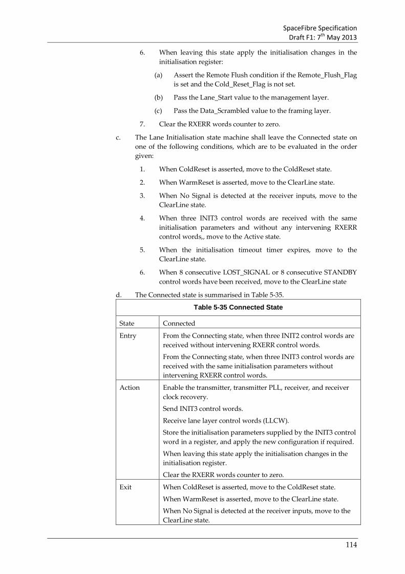
SpaceFibre Specification Draft F1: 7th May 2013
114
6. When leaving this state apply the initialisation changes in the initialisation register:
(a) Assert the Remote Flush condition if the Remote_Flush_Flag is set and the Cold_Reset_Flag is not set.
(b) Pass the Lane_Start value to the management layer.
(c) Pass the Data_Scrambled value to the framing layer.
7. Clear the RXERR words counter to zero.
c. The Lane Initialisation state machine shall leave the Connected state on one of the following conditions, which are to be evaluated in the order given:
1. When ColdReset is asserted, move to the ColdReset state.
2. When WarmReset is asserted, move to the ClearLine state.
3. When No Signal is detected at the receiver inputs, move to the ClearLine state.
4. When three INIT3 control words are received with the same initialisation parameters and without any intervening RXERR control words,, move to the Active state.
5. When the initialisation timeout timer expires, move to the ClearLine state.
6. When 8 consecutive LOST_SIGNAL or 8 consecutive STANDBY control words have been received, move to the ClearLine state
d. The Connected state is summarised in Table 5-35.
Table 5-35 Connected State
State Connected
Entry From the Connecting state, when three INIT2 control words are received without intervening RXERR control words.
From the Connecting state, when three INIT3 control words are received with the same initialisation parameters without intervening RXERR control words.
Action Enable the transmitter, transmitter PLL, receiver, and receiver clock recovery.
Send INIT3 control words.
Receive lane layer control words (LLCW).
Store the initialisation parameters supplied by the INIT3 control word in a register, and apply the new configuration if required.
When leaving this state apply the initialisation changes in the initialisation register.
Clear the RXERR words counter to zero.
Exit When ColdReset is asserted, move to the ColdReset state.
When WarmReset is asserted, move to the ClearLine state.
When No Signal is detected at the receiver inputs, move to the ClearLine state.

SpaceFibre Specification Draft F1: 7th May 2013
115
When three INIT3 control words are received with the same initialisation parameters and without any intervening RXERR control words, move to the Active state.
When the initialisation timeout timer expires, move to the ClearLine state.
When 8 consecutive LOST_SIGNAL or 8 consecutive STANDBY control words have been received, move to the ClearLine state
5.7.1.10 Active state a. The Lane Initialisation state machine shall enter the Active state on the
following conditions:
1. From the Connected state, when three INIT3 control words with the same capability field value have been received without intervening RXERR control words.
NOTE The Lane Initialisation state machine enters the Active state when initialisation is complete.
b. When in the Active state the Lane Initialisation state machine shall initiate the following actions:
1. Stop the initialisation timeout timer.
2. Enable the transmitter, transmitter PLL, receiver, and receiver clock recovery.
3. Enable transmission of data and control words from the multi-lane or quality layer.
4. Pass received data and control words up to the multi-lane or quality layer.
5. Increase the RXERR words counter when a RXERR is received.
6. Decrease the RXERR words counter by one every time 16384 more words have been received.
7. Filter out Lane control words (see Table 5-7) so that they are not passed up to the multi-lane or quality layer.
NOTE They are used by the Lane Initialisation state machine and nothing is passed up to the multi-lane layer or quality layer in their place.
c. The Lane Initialisation state machine shall leave the Active state on one of the following conditions, which are to be evaluated in the order given:
1. When ColdReset is asserted, move to the ColdReset state.
2. When WarmReset is asserted, move to the ClearLine state.
3. When No Signal at Receiver signal is asserted indicating that there is a loss of signal at the receiver, move to the LossOfSignal state.

SpaceFibre Specification Draft F1: 7th May 2013
116
4. When the RX_ERR words counter reaches 255, move to the LossOfSignal state.
NOTE If the RXERR words error counter reaches 255 the bit error rate in the lane is very high and the lane needs to be reinitialised to try to recover correct operation.
5. When an INIT1 control word is received, move to the LossOfSignal state.
6. When the Lane_Start and Auto_Start signals are both de-asserted, move to the PrepareStandby state.
7. When 8 consecutive LOST_SIGNAL or 8 consecutive STANDBY control words have been received, move to the ClearLine state.
d. The Active state is summarised in Table 5-36 Active State.
Table 5-36 Active State
State Active
Entry From the Connected state, when three INIT3 control words with the same initialisation parameters have been received without intervening RXERR control words..
Action Stop the initialisation timeout timer.
Enable the transmitter, transmitter PLL, receiver, and receiver clock recovery.
Enable transmission of data and control words from the multi-lane control or quality layer.
Pass received data and control words up to the multi-lane control or quality layer.
Increase the RXERR words counter when a RXERR is received.
Decrease the RXERR words counter by one every time 16384 more words have been received.
Filter out Lane control words (see Table 5-7) so that they are not passed up to the multi-lane control or quality layer.
Exit When ColdReset is asserted, move to the ColdReset state.
When WarmReset is asserted, move to the ClearLine state.
When No Signal at Receiver signal is asserted indicating that there is a loss of signal at the receiver, move to the LossOfSignal state.
When the RX_ERR words counter reaches 255, move to the LossOfSignal state.
When an INIT1 control word is received, move to the LossOfSignal state.
When the Lane_Start and Auto_Start signals are both de-asserted, move to the PrepareStandby state.
When 8 consecutive LOST_SIGNAL or 8 consecutive STANDBY control words have been received, move to the ClearLine state.

SpaceFibre Specification Draft F1: 7th May 2013
117
5.7.1.11 PrepareStandby state a. The Lane Initialisation state machine shall enter the PrepareStandby state
on the following condition:
1. From the Active state, when Lane_Start and AutoStart signals are both de-asserted.
b. When in the PrepareStandby state the Lane Initialisation state machine shall initiate the following action:
1. Send 32 STANDBY control words.
NOTE 32 STANBY control words are sufficient to make sure that the first STANDBY control word has passed through the receive pipeline and receive elastic buffer at the far end of the lane, before the subsequent No Signal at receiver, caused by the near end of the lane entering the ClearLine state, is detected by the far end receiver.
c. The Lane Initialisation state machine shall leave the PrepareStandby state on one of the following conditions, which are to be evaluated in the order given:
1. When ColdReset is asserted, move to the ColdReset state.
2. When WarmReset is asserted, move to the ClearLine state.
3. When 32 STANDBY control words have been sent, move to the ClearLine state.
4. When 8 consecutive LOST_SIGNAL or 8 consecutive STANDBY control words have been received, move to the ClearLine state.
d. The PrepareStandby state is summarised in Table 5-37.
Table 5-37 PrepareStandby State
State PrepareStandby
Entry From the Active state, when Lane_Start and Auto_Start signals are both de-asserted.
Action Send 32 STANDBY control words.
Exit When ColdReset is asserted, move to the ColdReset state.
When WarmReset is asserted, move to the ClearLine state.
When 32 STANDBY control words have been sent, move to the ClearLine state.
When 8 consecutive LOST_SIGNAL or 8 consecutive STANDBY control words have been received, move to the ClearLine state.

SpaceFibre Specification Draft F1: 7th May 2013
118
5.7.1.12 LossOfSignal state a. The Lane Initialisation state machine shall enter the LossOfSignal state on
the following conditions:
1. From the Active state when No Signal at Receiver signal is asserted, indicating that there is no signal present on the receiver inputs.
2. From the Active state when the RX_ERR words counter overflows.
NOTE A counter increases its value every time a RX_ERR word is received, and periodically decreases its value (leaky-bucket counter). The overflow of this counter causes the output condition from Active state and an indication of a persistent error.
b. When in the LossOfSignal state the Lane Initialisation state machine shall initiate the following actions:
1. Send 32 LOST_SIGNAL control words.
2. Pass at least one (RXERR) word up to the multi-lane or quality layer.
c. The Lane Initialisation state machine shall leave the LossOfSignal state on one of the following conditions, which are to be evaluated in the order given:
1. When ColdReset is asserted, move to the ColdReset state.
2. When WarmReset is asserted, move to the ClearLine state.
3. When 32 LOST_SIGNAL control words have been sent, move to the ClearLine state.
4. When 8 consecutive LOST_SIGNAL or 8 consecutive STANDBY control words have been received, move to the ClearLine state.
d. The LossOfSignal state is summarised in Table 5-38.
Table 5-38 LossOfSignal State
State LossOfSignal
Entry From the Active state when No Signal at Receiver signal is asserted, indicating that there is no signal present on the receiver inputs.
From the Active state when the RX_ERR words counter overflows.
Action Send 32 LOST_SIGNAL control words.
Pass at least one (RXERR) word up to the multi-lane or quality layer.
Exit When ColdReset is asserted, move to the ColdReset state.
When WarmReset is asserted, move to the ClearLine state.
When 32 LOST_SIGNAL control words have been sent, move to

SpaceFibre Specification Draft F1: 7th May 2013
119
the ClearLine state.
When 8 consecutive LOST_SIGNAL or 8 consecutive STANDBY control words have been received, move to the ClearLine state.
5.7.2 Data rate adjustment a. The transmitters at each end of a lane shall send data at the same nominal
data signalling rate.
b. The maximum permitted difference in the data signalling rates, when each end of the lane is operating at nominally the same data signalling rate (e.g. 2 Gbits/s) shall be 100 parts per million.
NOTE The data signalling rate of a transmitter at one end of a lane and a receiver at the other end of a lane might be different due to differences in the local clocks being used at each end of the lane.
c. A receive elastic buffer shall be used to compensate for differences in the data signalling rate at each end of the lane.
d. Skip control words shall be inserted regularly in the transmit data stream.
NOTE When a SKIP arrives at the receiver at the other end of the lane it might have been inverted by PCB layout to form an inverse SKIP control word.
e. A skip control word shall be sent every 5,000 words.
f. When a skip or inverse skip control word is read from a receive elastic buffer that is more than half full, the skip or inverse skip control word shall be removed from the receive elastic buffer and the following character shall be read from the buffer.
g. When a skip or inverse skip control word is read from a receive elastic buffer that is less than half full, the skip or inverse skip control word shall be left in the buffer, so that it can be read again the next time the buffer is read.
h. A particular skip or inverse skip control word shall be read at most twice, i.e. the second time it is read it is removed from the receive elastic buffer.
5.7.3 Idle words a. When there is no other data or control word to send an idle word shall be
sent.
NOTE It is essential not to have gaps in the data being sent because the PLL in the receiver has to maintain lock on the incoming data stream.
b. When received, idle or inverse idle control words shall be discarded when they are read out of the receive elastic buffer.

SpaceFibre Specification Draft F1: 7th May 2013
120
NOTE Although only IDLEs are sent they might be inverted into inverse IDLEs by the time they reach the receiver.
5.7.4 Parallel loopback a. A parallel loopback facility should be provided in the SpaceFibre CODEC
for test purposes.
NOTE This facility is optional.
b. When enabled, the parallel loopback shall pass the stream of words to be transmitted from the lane layer to the receive input of the lane layer.
NOTE This connects the output of the transmit side of the lane layer to the input of the receive side of the lane layer.
5.7.5 8B/10B encode/decode a. The SpaceFibre CODEC shall use 8B/10B encoding to encode each 8-bit
data character or control code into a 10-bit symbol that is transmitted.
NOTE 8B/10B encoding is described in A2.2.
b. To ensure DC balancing of the transmitted signal account shall be kept of the current running disparity in the transmitter.
c. If the current running disparity is positive when encoding an 8-bit character or control code, the symbol for that data character or control code which has negative disparity shall be used.
d. If the current running disparity is positive when encoding an 8-bit character or control code, and there is no symbol for that data character or control code which has negative disparity, the symbol with neutral shall be used.
e. If the current running disparity is negative when encoding an 8-bit character or control code, the symbol for that data character or control code which has positive disparity shall be used.
f. If the current running disparity is negative when encoding an 8-bit character or control code, and there is no symbol for that data character or control code which has positive disparity, the symbol with neutral shall be used.
g. To detect disparity errors account shall be kept of the current running disparity in the receiver.
h. If the current running disparity is more than plus one or less minus one, this shall indicate a disparity error.
i. If a disparity error occurs, it shall be indicated to the receive synchronisation state machine and the current symbol shall be set to K0.0.
j. When a symbol is received it shall be decoded into an 8-bit data character or control code using the 8B/10B symbol table.

SpaceFibre Specification Draft F1: 7th May 2013
121
k. If an unrecognised symbol is received then a symbol error shall be indicated to the receive synchronisation state machine and the current symbol shall be set to K0.0.
l. The 8B/10B encoding shall with the least-significant five bits being encoded as detailed in Table 5-39 and the most significant three bits being encoded as detailed in Table 5-40.

SpaceFibre Specification Draft F1: 7th May 2013
122
Table 5-39 5B/6B Encoding Input Output
Data Input Data bits 43210
(EDCBA)
Current Running Disparity -ve
abcdei
Current Running Disparity +ve
abcdei D00.y 00000 100111 011000
D01.y 00001 011101 100010
D02.y 00010 101101 010010
D03.y 00011 110001
D04.y 00100 110101 001010
D05.y 00101 101001
D06.y 00110 011001
D07.y 00111 111000 000111
D08.y 01000 111001 000110
D09.y 01001 100101
D10.y 01010 010101
D11.y 01011 110100
D12.y 01100 001101
D13.y 01101 101100
D14.y 01110 011100
D15.y 01111 010111 101000
D16.y 10000 011011 100100
D17.y 10001 100011
D18.y 10010 010011
D19.y 10011 110010
D20.y 10100 001011
D21.y 10101 101010
D22.y 10110 011010
D/K23.y 10111 111010 000101
D24.y 11000 110011 001100
D25.y 11001 100110
D26.y 11010 010110
D/K27.y 11011 110110 001001
D28.y 11100 001110
K28.y 11100 001111 110000
D/K29.y 11101 101110 010001
D/K30.y 11110 011110 100001
D31.y 11111 101011 010100
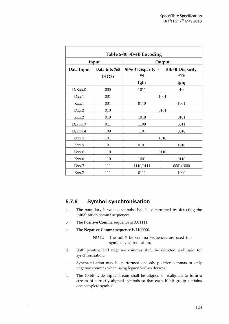
SpaceFibre Specification Draft F1: 7th May 2013
123
Table 5-40 3B/4B Encoding Input Output
Data Input Data bits 765
(HGF)
5B/6B Disparity -ve
fghj
5B/6B Disparity +ve
fghj D/Kxx.0 000 1011 0100
Dxx.1 001 1001
Kxx.1 001 0110 1001
Dxx.2 010 0101
Kxx.2 010 1010 0101
D/Kxx.3 011 1100 0011
D/Kxx.4 100 1101 0010
Dxx.5 101 1010
Kxx.5 101 0101 1010
Dxx.6 110 0110
Kxx.6 110 1001 0110
Dxx.7 111 1110/0111 0001/1000
Kxx.7 111 0111 1000
5.7.6 Symbol synchronisation a. The boundary between symbols shall be determined by detecting the
initialisation comma sequences.
b. The Positive Comma sequence is 0011111.
c. The Negative Comma sequence is 1100000.
NOTE The full 7 bit comma sequences are used for symbol synchronisation.
d. Both positive and negative commas shall be detected and used for synchronisation.
e. Synchronisation may be performed on only positive commas or only negative commas when using legacy SerDes devices.
f. The 10-bit wide input stream shall be aligned or realigned to form a stream of correctly aligned symbols so that each 10-bit group contains one complete symbol.

SpaceFibre Specification Draft F1: 7th May 2013
124
g. The 10-bit wide input stream shall be realigned every time a comma sequence is detected in a different position to the position of the last comma detected.
h. When a 20-bit or 40-bit interface is being used from the 8B/10B receiver, realignment may occur on the first comma in a word, i.e. when there are two or more commas in a 20-bit or 40-bit word it will be the comma in the lower significant bit position that is used for symbol realignment.
5.7.6.2 Receive Synchronisation State Machine a. A receive synchronisation state machine shall be used to determine when
incoming symbols are properly synchronised.
NOTE The state diagram for the receive synchronisation state machine is illustrated in Figure 5-10.
CheckSync
LostSync
Ready
Comma sequence received
> 4 Four RX errors OR
Word realignment
All symbols in a word are valid
One symbol in a word is
invalid
No comma sequence received
Word realignment
Not RX error ANDNot word realignment
RX error = disparity or invalid symbol error
ColdResetOR WarmReset
Word realignment = word synchronisation lost (i.e. comma sequence in position other than LS byte)
RX error
Figure 5-10 Receive Synchronisation State Machine
5.7.6.2.2 LostSync State
a. The LostSync state shall be entered on one of the following conditions:
1. ColdReset command.
2. WarmReset command.
3. From the CheckSync state, when word realignment occurs or when a total of more than four symbols are received that are invalid or contain a disparity error.
4. From the Ready state, when word realignment occurs.
b. When in the LostSync state the Receive Synchronisation state machine shall initiate the following actions:
1. Replace any received data and control words with RXERR control words.

SpaceFibre Specification Draft F1: 7th May 2013
125
c. The Receive Synchronisation state machine shall leave the LostSync State on one of the following conditions, which shall be evaluated in the order given:
1. When a comma sequence is received, move to the CheckSync state.
d. The LostSync state is summarised in Table 5-41.
Table 5-41 LostSync State
State LostSync
Entry ColdReset command.
WarmReset command.
From the CheckSync state, when word realignment occurs or when a total of more than four symbols are received that are invalid or contain a disparity error.
From the Ready state, when word realignment occurs.
Action Replace received data and control words with RXERR control words.
Exit When a comma sequence is received, move to the CheckSync state.
5.7.6.2.3 CheckSync State
a. The CheckSync state shall be entered on one of the following conditions:
1. From the LostSync state, when a comma sequence is received.
2. From the Ready state, when a disparity error occurs or an invalid symbol is detected.
b. When in the CheckSync state the Receive Synchronisation state machine shall initiate the following actions:
1. If any symbol in a received word is invalid or has a disparity error, replace that received word with an RXERR control word.
2. Count the number of symbols received that are invalid or contain a disparity error.
c. The Receive Synchronisation state machine shall leave the CheckSync State on one of the following conditions, which shall be evaluated in the order given:
1. When ColdReset is asserted, move to the LostSync state.
2. When WarmReset is asserted, move to the CheckSync state.
3. When word realignment occurs, move to the LostSync state.
4. When a total of more than four symbols are received that are invalid or contain a disparity error, move to the LostSync state.
NOTE These four invalid or erroneous symbols need not be sequential i.e. there may be valid symbols interspersed amongst them.

SpaceFibre Specification Draft F1: 7th May 2013
126
5. When all symbols within a word are valid, move to the Ready state.
d. The CheckSync state is summarised in Table 5-42.
Table 5-42 CheckSync State
State CheckSync
Entry From the LostSync state, when a comma sequence is received.
From the Ready state, when a disparity error occurs or an invalid symbol is detected.
Action If any symbol in a received word is invalid or has a disparity error, replace that received word with an RXERR control word.
Count the number of symbols received that are invalid or contain a disparity error.
Exit When ColdReset is asserted, move to the LostSync state.
When WarmReset is asserted, move to the CheckSync state.
When word realignment occurs, move to the LostSync state.
When a total of more than four symbols are received that are invalid or contain a disparity error, move to the LostSync state.
When all symbols within a word are valid, move to the Ready state.
5.7.6.2.4 Ready State
a. The Ready state shall be entered on one of the following conditions:
1. From the CheckSync state, when all symbols within a word are valid.
b. When in the Ready state the Receiver Synchronisation state machine shall initiate the following actions:
1. Receive symbols.
c. The Receiver Synchronisation state machine shall leave the Ready state on one of the following conditions, which shall be evaluated in the order given:
1. When ColdReset is asserted, move to the LostSync state.
2. When WarmReset is asserted, move to the CheckSync state.
3. When a disparity error occurs or an invalid symbol is received, move to the CheckSync state.
4. When word realignment occurs, move to the LostSync state.
d. The Ready state is summarised in Table 5-43.
Table 5-43 Ready State
State Ready
Entry From the CheckSync state, all symbols within a word are valid.
Action Receive symbols.
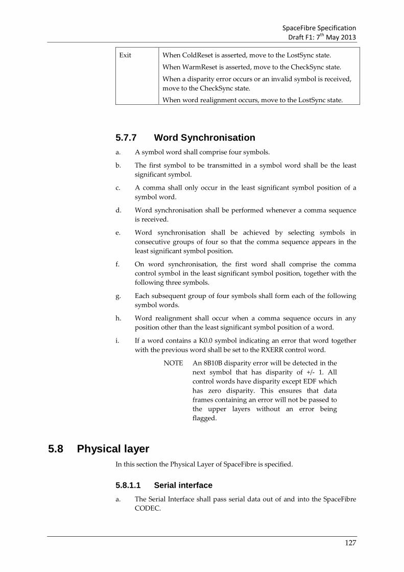
SpaceFibre Specification Draft F1: 7th May 2013
127
Exit When ColdReset is asserted, move to the LostSync state.
When WarmReset is asserted, move to the CheckSync state.
When a disparity error occurs or an invalid symbol is received, move to the CheckSync state.
When word realignment occurs, move to the LostSync state.
5.7.7 Word Synchronisation a. A symbol word shall comprise four symbols.
b. The first symbol to be transmitted in a symbol word shall be the least significant symbol.
c. A comma shall only occur in the least significant symbol position of a symbol word.
d. Word synchronisation shall be performed whenever a comma sequence is received.
e. Word synchronisation shall be achieved by selecting symbols in consecutive groups of four so that the comma sequence appears in the least significant symbol position.
f. On word synchronisation, the first word shall comprise the comma control symbol in the least significant symbol position, together with the following three symbols.
g. Each subsequent group of four symbols shall form each of the following symbol words.
h. Word realignment shall occur when a comma sequence occurs in any position other than the least significant symbol position of a word.
i. If a word contains a K0.0 symbol indicating an error that word together with the previous word shall be set to the RXERR control word.
NOTE An 8B10B disparity error will be detected in the next symbol that has disparity of +/- 1. All control words have disparity except EDF which has zero disparity. This ensures that data frames containing an error will not be passed to the upper layers without an error being flagged.
5.8 Physical layer In this section the Physical Layer of SpaceFibre is specified.
5.8.1.1 Serial interface a. The Serial Interface shall pass serial data out of and into the SpaceFibre
CODEC.

SpaceFibre Specification Draft F1: 7th May 2013
128
b. The serial interface shall comprise a transmitter serial output and a receiver serial input.
5.8.1.1.1 Transmit serial output The Transmit Serial Output shall contain the signals listed in Table 5-44.
Table 5-44 Transmit Serial Interface
Signal Function Txp Positive side of the differential serial transmitter output.
Txn Negative side of the differential serial transmitter output.
5.8.1.1.2 Receive serial input The Receive Serial Input shall contain the signals listed in Table 5-45.
Table 5-45 Receiver Serial Interface
Signal Function Rxp Positive side of the differential serial receiver input.
Rxn Negative side of the differential serial receiver input.
5.8.2 Serialisation
5.8.2.1 Bit Synchronisation a. The receive clock used to sample the incoming bit stream, shall be
generated by a clock recovery circuit that matches the phase of a local receive clock to the transitions of the incoming bit stream.
b. Sampling of the bit stream should be close (+/- 20% TBC) to the centre of the bit period.
c. The clock recovery circuit should indicate in a status register when bit synchronisation is achieved.
NOTE This is for status information only.
5.8.2.2 Serialiser/deserialiser a. 10-bit symbols shall be transmitted serially over the physical medium.
b. At the transmitter a serialiser shall be used to convert each parallel 10-bit symbol into a serial bit stream with each bit of the symbol being send one after the other.
NOTE One, two or four symbols can be provided to the serialiser in parallel.
c. The least significant bit of the 10-bit symbol shall be transmitted first.
d. At the receiver the incoming bit stream shall be converted to a 10-bit word by sampling the bit stream with a receive clock in a deserialiser.
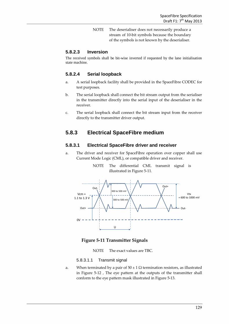
SpaceFibre Specification Draft F1: 7th May 2013
129
NOTE The deserialiser does not necessarily produce a stream of 10-bit symbols because the boundary of the symbols is not known by the deserialiser.
5.8.2.3 Inversion The received symbols shall be bit-wise inverted if requested by the lane initialisation state machine.
5.8.2.4 Serial loopback a. A serial loopback facility shall be provided in the SpaceFibre CODEC for
test purposes.
b. The serial loopback shall connect the bit stream output from the serialiser in the transmitter directly into the serial input of the deserialiser in the receiver.
c. The serial loopback shall connect the bit stream input from the receiver directly to the transmitter driver output.
5.8.3 Electrical SpaceFibre medium
5.8.3.1 Electrical SpaceFibre driver and receiver a. The driver and receiver for SpaceFibre operation over copper shall use
Current Mode Logic (CML), or compatible driver and receiver.
NOTE The differential CML transmit signal is illustrated in Figure 5-11.
Vcm = 1.1 to 1.3 V
U
0V
Out+
Out- Out+
Out-
Vtx= 600 to 1000 mV
300 to 500 mV
300 to 500 mV
Figure 5-11 Transmitter Signals
NOTE The exact values are TBC.
5.8.3.1.1 Transmit signal
a. When terminated by a pair of 50 ± 1 Ω termination resistors, as illustrated in Figure 5-12 , The eye pattern at the outputs of the transmitter shall conform to the eye pattern mask illustrated in Figure 5-13.

SpaceFibre Specification Draft F1: 7th May 2013
130
50Ω
50Ω
Out+
Out- Vterm
Zbias
Vcc
Vout+
Vout-
Figure 5-12 Transmitter test circuit
0.18U 0.12U0.4U
0V
+300mV
Differential Signal
Amplitude(Out+) – (Out-)
-300mV
0.12U 0.18U
+500mV
-500mV
Figure 5-13 Transmitter eye pattern mask
a. The two outputs of the CML transmitter (Out+ and Out-) shall have a common mode voltage, Vcm, of 1.1 V to 1.3 V.
b. The differential output of the transmitter (Out+ - Out-) shall have amplitude of 600 mV to 1000 mV, as illustrated in Figure 5-13.
c. The differential output of the transmitter (Out+ - Out-) shall have a rise time (Tr) and fall time (Tf) of less than 50 ps.
5.8.3.1.2 Receive signal
a. The eye pattern measured at the receiver inputs shall not be permitted to enter the mask region shaded in Figure 5-14.
b. The receive eye pattern shall be measured across the receiver termination resistor using a using a wide bandwidth oscilloscope with differential probes (bandwidth of at least 5 GHz for a 2.5 Gbits/s signal).
c. Where the termination resistors are internal to an integrated circuit, the receive eye pattern may be measured within 2 cm of the receiver pins on the integrated circuit.

SpaceFibre Specification Draft F1: 7th May 2013
131
0.3U 0.12U1.6U
0V
+100mVDifferential
Signal Amplitude(In+) – (In-)
-100mV
0.12U 0.3U
+500mV
-500mV
Figure 5-14: Receiver eye pattern mask
d. The positive input threshold for the differential receive signal shall be +100 mV.
e. A differential signal greater than the positive input threshold shall result in logic 1 at the receiver output.
f. The negative input threshold for the differential receive signal shall be -100 mV.
g. A differential signal less than the negative input threshold shall result in logic 0 at the receiver output.
5.8.3.2 Electrical SpaceFibre PCB tracks a. The PCB tracks for electrical SpaceFibre shall be 100 ohms differential
impedance +/- 5 ohms.
b. Two pairs of differential PCB tracks shall be used for a bi-directional SpaceFibre link, one pair for each direction.
5.8.3.3 EGSE electrical connectors a. For electrical ground support equipment (EGSE) external serial ATA
connectors shall be used as specified in Serial ATA Revision 3.0, clause 6.5.1.
5.8.3.4 EGSE cable a. For electrical ground support equipment (EGSE) external serial ATA
cable shall be used specified in Serial ATA Revision 3.0, clause 6.6.1.
5.8.3.5 EGSE cable assemblies a. For electrical ground support equipment (EGSE) a crossover external
serial ATA cable shall be used.

SpaceFibre Specification Draft F1: 7th May 2013
132
b. The EGSE cable assembly shall be terminated at each end by an External Serial ATA cable receptacle as detailed in Serial ATA Revision 3.0, clause 6.5.1 and Figure 93 of that specification.
c. The EGSE cable assembly shall use the external serial ATA cable specified clause 5.8.3.4.
d. The EGSE cable assembly shall be wired as illustrated in Figure 5-15.
TX +
TX -
A +
A -
GND
GND
2
3
1
4
B -
B +
GND
5
6
7
RX -
RX +
6
5
7
4
3
2
1
B +
B -
GND
GND
A -
A +
GND
TX -
TX +
RX +
RX -
shield
cable assembly
cable receptacle
cable receptacle
deviceplug
deviceplug
shieldPCB
tracksPCB
tracksSpaceFibreCODEC
SpaceFibreCODEC
Figure 5-15 SpaceFibre EGSE cable assembly
5.8.3.6 Flight electrical connectors a. For flight equipment connections conforming to ESCC specification (draft
07072-ST-MDSA HDR -01) shall be used.
5.8.3.6.1 Male connectors
a. Male two way connectors (variant 05) shall be used for cable assemblies.
5.8.3.6.2 Female connectors
a. Female two way connectors (variant 08) shall be used for EGSE to flight adaptor cable assemblies.
5.8.3.6.3 PCB mounting female connectors
a. Female two way PCB panel mounting connectors (variant 02) or female two way PCB mounting connectors (variant 11) shall be used for connecting to a PCB.
5.8.3.7 Flight cable a. Flight cable shall be PTFE coaxial cable that conforms to the cable
specification in ESCC specification (draft 07072-ST-MDSA HDR -01), clause 4.4.7.
5.8.3.8 Flight cable assemblies a. Male connectors 2 way connectors conforming to clause 5.8.3.6 shall be
used on flight cable assemblies.
b. The flight cable assembly shall use the co-axial cable specified in clause 5.8.3.7.
c. The flight cable assembly shall be wired as illustrated in Figure 5-16.

SpaceFibre Specification Draft F1: 7th May 2013
133
TX +
TX -
1
2
1
2
3
4
3
4
RX -
RX +
4
3
2
1
4
3
2
1
TX -
TX +
RX +
RX -
cable assembly
connectormale
connectormale
connectorfemale
Individual shields
PCBtracks
PCBtracks
SpaceFibreCODEC
SpaceFibreCODEC
backshellconnector
bodyconnector
body backshell
connectorfemale
Figure 5-16 SpaceFibre flight cable assembly
5.8.3.1 EGSE to flight adaptor cable assemblies a. The EGSE to flight adaptor cable assembly shall allow a SpaceFibre EGSE
unit to connect to a flight cable assembly.
b. One end of the EGSE to flight adaptor cable assembly shall be terminated by an External Serial ATA cable receptacle as detailed in Serial ATA Revision 3.0, clause 6.5.1 and Figure 93 of that specification.
c. The other end of the EGSE to flight adaptor cable assembly shall be terminated by a female 2 way connector conforming to clause 5.8.3.6.2.
d. The EGSE to flight adaptor cable assembly shall use the co-axial cable specified in clause 5.8.3.7.
e. The EGSE to flight adaptor cable assembly shall be wired as illustrated in Figure 5-17.
4
3
2
1
4
3
2
1
TX -
TX +
RX +
RX -
cable assembly
connectormale
connectorfemale
Individual shields
PCBtracks
SpaceFibreCODEC
Flight Unit
backshellconnector
body
TX +
TX -
A +
A -
GND
GND
2
3
1
4
B -
B +
GND
5
6
7
RX -
RX +
cable receptacle
deviceplug
PCBtracks
SpaceFibreCODEC
EGSE Unit
Figure 5-17 SpaceFibre EGSE to flight adaptor cable assembly
f. The lengths of the co-axial cables used in the cable assembly shall be matched to within 1% and to within +/- 3 mm maximum.
5.8.3.2 Flight connector savers a. One male 2 way connector and one female 2 way connector conforming
to clause 5.8.3.6 shall be used on flight connector savers.
b. The flight connector shall use the co-axial cable specified in clause 5.8.3.7 to wire between the connectors.
c. The flight connector saver shall be wired as illustrated in Figure 5-16.

SpaceFibre Specification Draft F1: 7th May 2013
134
1
2
3
4
1
2
3
4
Connector saver
connectormale
connectorfemale
Individual shields
backshellbackshell
Figure 5-18 SpaceFibre flight connector saver
d. The length of the co-axial cables used in the flight connector shall be of the same length within +/- 1 mm and of maximum length 100 mm.
5.8.4 Fibre optic driver and receiver
5.8.4.1 Fibre optic driver and receiver a. TBA
5.8.4.2 Fibre optic connectors a. TBA
5.8.4.3 Fibre optic cables a. TBA
5.9 Management layer In this section the Management Layer of SpaceFibre is specified.
a. The management layer shall provide a means of configuring the SpaceFibre interface and reading its status.
b. Configuration of the SpaceFibre interface shall be performed by writing to management parameters via the management interface.
c. Reading of the status of the SpaceFibre interface shall be performed by reading status values via the management interface.
5.9.2 Configuration parameters a. It shall be possible to read and write configuration parameters via the
management interface.
b. The configuration parameters are listed in Table 5-46.
c. The configuration parameters shall be cleared on cold reset.

SpaceFibre Specification Draft F1: 7th May 2013
135
Table 5-46 SpaceFibre Interface Configuration Parameters
Layer Parameter Description Cold Reset value
Virtual Channel
VC number (VC buffer)
Virtual Channel number assigned to the hardware buffer identified by the VC buffer parameter.
This parameter shall only be configured following a cold reset.
Each VC is given a consecutive number starting a 0.
Priority level (VC buffer)
Priority level (0-15) assigned to a particular virtual channel.
15
Expected Bandwidth (VC buffer)
The fraction of overall link bandwidth assigned to a particular virtual channel.
See section 5.5.1.4.5 r)
Number of Time Slots
Number of time slots in the schedule.
The maximum number of time slots in a schedule shall be 256. An implementation may provide a hardcoded value that cannot be changed.
256
Allocated Time Slots (VC buffer)
The time slots in which a particular virtual channel is permitted to send data frames.
This parameter is an array of N bits, where N is the number of time slots in the schedule. A bit is set to one to indicate that the virtual channel can send data in the corresponding time slot.
All ones
Virtual Channel Idle Time Limit
Determines the maximum time a channel can be idle without sending data before the underuse indication is raised. The period value can be hardcoded or can be provided by an optional configuration parameter for all VC channels or for each VC channel independently.
1 ms
Multi-Lane layer
Required lanes
Required number of lanes to be used to form the SpaceFibre link.
Lane Layer Start mode (lane)
Asserts or deasserts Lane_Start for the corresponding lane.
0

SpaceFibre Specification Draft F1: 7th May 2013
136
Autostart (lane)
Asserts or deasserts AutoStart for the corresponding lane.
0
5.9.3 Status parameters a. It shall be possible to read and write configuration parameters via the
management interface.
b. The mandatory status parameters shall be as listed in Table 5-47.
c. Implementations may provide additional status information for debugging purpose.
NOTE Basic protocol and interface debugging can be done using just the mandatory status parameters.
d. The way the status parameters are cleared shall be implementation dependent.
e. The status parameters shall be cleared on warm reset. and cold reset.

SpaceFibre Specification Draft F1: 7th May 2013
137
Table 5-47 SpaceFibre Interface Status Parameters
Layer Parameter Description
Virtual Channel
BW over use (VC buffer)
Indicates that the hardware buffer is using much more bandwidth than expected and has reached the minimum bandwidth credit value.
BW under use (VC buffer)
Indicates that the hardware buffer is using less bandwidth than expected and that the bandwidth credit has remained at its maximum value for a certain time (the maximum expected Idle time).
Has Credit (VC buffer)
Indicates that there is space in the input buffer at the other end of the link (destination).
Input buffer overflow (VC buffer)
Indicates that an input buffer is receiving data when it is full. This should not happen and indicates a fatal protocol error.
Broadcast layer
BC missed Set when the broadcast sequence is two more than the last value.
Sequence error
Set when the broadcast sequence is different and not one or two more than the last value received. Should not be set when it is the first value received after a cold reset.
Quality layer
CRC-16 error Set when a CRC-16 error has occurred. This indicates that one or multiple lanes are producing multiple bit errors, which is not expected under nominal operation.
CRC-8 or sequence error
Set when a CRC-8 or a sequence error occurs. This can occur under nominal operation.
Retry buffer empty
Set when the retry buffer is empty. This indicates that all data from the virtual channels has been sent and acknowledged.
Number of retries
The number of retries made by the SpaceFibre CODEC. Incremented by one for every retry event initiated.
Lane Layer Lane Active (lane)
Set when the lane is in active state
LossOfSignal (lane)
Set when LossOfSignal is detected in Active state.
RxError Counter
Value of the RxError Counter. Can be used to obtain the current BER.

SpaceFibre Specification Draft F1: 7th May 2013
138
(lane)
RxError overflow (lane)
Set when RxError counter overflows in Active state.
Standby (lane)
Set when Standby words are received.
Timeout (lane)
Set when a connection timeout occurs.
LOS (lane)
Set when Loss Of Signal words are received.
Remote Flush (lane)
Set when a Remote Flush is received.
RX Polarity
(lane)
Set when the receiver polarity is inverted.
Serialisation Symbol Sync Set when symbol synchronisation is achieved.
5.9.4 Reset a. The effects of cold reset on the SpaceFibre interface shall be as indicated
in Table 5-48.
b. The effects of warm reset on the SpaceFibre interface shall be as indicated in Table 5-48.

SpaceFibre Specification Draft F1: 7th May 2013
139
Table 5-48 Effects of Cold Reset and Warm Reset
Layer Variable Cold Reset
Warm Reset
Virtual Channel Output VCBs Flushed Unchanged
Input VCBs Flushed Unchanged
FCT counter Cleared Unchanged
Priority level Set to 15 Unchanged
Expected Bandwidth
VC0 set to 10%
All other VCs set to 0%
Unchanged
Bandwidth credit
Set to zero
Set to zero
Input space counter
Set to buffer size
Unchanged
FCT credit counter
Set to zero
Unchanged
Allocated time slots
Set to 1 Unchanged
Virtual channel idle time limit
1ms Unchanged
Broadcast Message BC Sequence counter
Set to zero
Unchanged
Quality Transmit Sequence Counter
Set to zero
Unchanged
Receive Sequence Counter
Set to zero
Unchanged
Retry buffers Flushed Unchanged
PRBS seed Set to 0xffff ffff
Unchanged
Multi-lane control Required number of lanes
Set to one Unchanged
Distribution lane numbers
Clear Clear

SpaceFibre Specification Draft F1: 7th May 2013
140
Concentration lane numbers
Clear Clear
Lane Capability parameters
Reset Unchanged
Receiver bit inversion
Off Off
Start mode Off Unchanged
Autostart On Unchanged
Physical PLL Reset Reset
5.10 SpaceFibre conformance
5.10.1 Overview
5.10.2 Partial implementations Single lane
Bit inversion
Only positive or only negative comma synchronisation
Parallel loopback

SpaceFibre Specification Draft F1: 7th May 2013
141
Annex A(informative) Serial Data Link Concepts
This section provides an overview of several key concepts for high-speed serial data links.
A.1 Data Scrambling Data scrambling is a technique used to reduce the electro-magnetic (EM) emissions from a communications system. The data signal is convolved with a wideband signal which results in the spectrum of the data being broadened. Possible peaks in the EM spectrum of the original data signal are spread out reducing the energy at any single frequency. Note that data scrambling does not guarantee reduced peaks in the EM spectrum since it is possible that the scrambling produces a bit sequence with a higher spectral peaks than the original signal. However, for regular bit sequences it is likely to reduce the spectral peaks.
A random number generator is used to produce the wideband signal which is XORed with the data being transmitted. At the beginning of each frame being transmitted the random number generator is reseeded with a specific value. A similar random number generator in the receiver, seeded with the same seed as in the transmitter at the start of every new frame, is used to de-scramble the data. The incoming data is XORed with the random number sequence to reveal the original data stream.
The random number generator is implemented using a linear feedback shift register as shown in Figure A-1. An example scrambling/de-scrambling polynomial is that used in PCI-Express:
G(x) = X16 + X5 + X4+ X3+ 1
The seed for the random number generator is FFFFh i.e. all flip-flops in the random number generator are set to 1.

SpaceFibre Specification Draft F1: 7th May 2013
142
Random Number GeneratorRandom Number Generator
Bit Stream InputBit Stream Input
D Q D Q D Q D Q D Q
D Q D Q D Q D Q D Q D Q D Q D Q
D Q D Q D Q D Q D Q D Q D Q D Q
D Q
D Q D Q
XOR XOR XOR
XOR
Data In
CLK
D7 D6 D4D5 D3 D2 D1 D0
D9 D11D10 D12 D13 D14 D15D6 D8D7
D3 D4 D5D0 D2D1
DataOut
Figure A-1 Scrambler / De-Scrambler
A.2 8B/10B Encoding and Decoding 8B/10B encoding encodes 8-bit data bytes into 10-bit characters for transmission. The 8B/10B encoding has several advantages over direct 8-bit transmission.
1. It provides a transmitted data stream with roughly the same number of 1’s as 0’s giving the data a zero DC bias, improving the transmission characteristics and enabling AC coupling.
2. Since a 10-bit code has 1024 possible values and not all of these are needed to send an 8-bit value there are spare valid codes left over that can be used for control codes.
3. It guarantees that there will be sufficient number of bit transitions in the serial data stream to enable the recovery of the bit clock using a phase-locked loop. A maximum of five consecutive ones or zeros are ensured with 8B/10B encoding.
4. Since all characters, both data and control characters, are transmitted with 10-bits the bit and character transmission rates are constant simplifying the transmission and reception of characters.
5. Codes that are unused by the 8B/10B encoding can be used to detect link errors i.e. if an unused code occurs then there has been a transmission error.
6. The current running disparity following 8B/10B encoding is always +1 or -1, any other value indicates a disparity error.
To avoid significant DC components 8B/10B encoding uses only the 10-bit codes that contain either 5 ones and 5 zeros, 6 ones and 4 zeros, or 4 ones and 6 zeros. There are enough of these to encode the 8-bit data byte and several possible control codes. Characters encoded with 5 ones and 5 zeros have neutral disparity and will produce zero DC bias. However, if a sequence of bytes was transmitted that contained characters all with 6 ones and 4 zeros the DC

SpaceFibre Specification Draft F1: 7th May 2013
143
component would slowly increase. A similar opposite effect would occur if the characters all contained 4 ones and 6 zeros. To prevent this increasing DC bias and to maintain an equal number of transmitted ones and zeros each character with an unequal number of ones and zeros has two possible codes one with 6 ones and 4 zeros and the other with 4 ones and 6 zeros.
Every time the transmitter sends a character with 6 ones and 4 zeros it will record the fact that it has sent more ones than zeros and the next time it has to send a character with an uneven number of bits it will choose the code that has 4 ones and 6 zeros. This keeps the average number of ones and zeros the same and eliminates any DC bias in the transmitted signal. The Current Running Disparity variable is set to one (positive) when more ones have been sent than zeros and to zero (negative) when more zeros have been sent than ones. Characters with 5 ones and 5 zeros have neutral disparity and do not affect the Current Running Disparity value. When a character with an unequal number of ones and zeros is to be sent, the value of the Current Running Disparity will determine which of the two possible 10-bit codes will be sent. If the Current Running Disparity is positive then the option with 4 ones and 6 zeros is sent, if it is negative then the other option with 6 ones and 4 zeros is transmitted.
Once all 256 possible values of an 8-bit data byte have been assigned a code with 5 ones and 5 zeros or a pair of codes with unequal numbers of ones and zeros, there are just 12 valid codes left out of the possible 1024 values of a 10-bit code. The others have more than six ones or more than six zeros and are invalid.
A.2.1 8B/10B Encoding 8B/10B encoding is normally done using a pair of look-up tables as shown in Figure A-2 rather than a single look-up table.
5B/6BEncoder
3B/4BEncoder
RunningDisparity
5 ls-bits 6-bits
3 ms-bits 4-bits
8-bit DataInput
Control/DataInput (K/D)
10-bit EncodedOutput5B/6B Disparity
3B/4B Disparity
Figure A-2 8B/10B Encoder
The 5B/6B and 3B/4B approach to 8B/10B encoding has lead to a specific notation for representing codes resulting from this encoding. This is illustrated in Figure A-3.

SpaceFibre Specification Draft F1: 7th May 2013
144
7 6 5 4 3 2 1 0
H G F E D C B A
H G F E D C B A
H G FE D C B A
ms ls
D/K
D/K
D/K
Data/Control
ASCII Character
8B/10B Notation
Sub-Blocks
Swap Sub-Blocks
Decimal values D/K XX Y
Notation D/KXX.Y
1 0 1 0 1 1 0 0
1 0 1 0 1 1 0 0
1 0 1 0 1 1 0 0
1 0 10 1 1 0 0
D
D
D
D 12 5
D12.5
1 0 1 1 1 1 0 0
1 0 1 1 1 1 0 0
1 0 1 1 1 1 0 0
1 0 11 1 1 0 0
K
K
K
K 28 5
K28.5
Examples
Figure A-3 8B/10B Notation The five least-significant bits are encoded first using a 5B/6B encoder. This takes into account whether the 5 least significant bits are part of a control or data word as determined by the K/D input and also the current running disparity of the link. The 5B/6B encoding table is given in Table A-1. This table has the following properties:
• The six bit outputs consist of either three ones and three zeros, four ones and two zeros or two ones and four zeros.
• When the output code has neutral disparity (three ones and three zeros) there is one code independent of the running disparity (except for D07.y which has two codes based on the running disparity). The complement of a neutral disparity code also has neutral disparity and, except for D07.y, corresponds to a different input symbol. By definition, using a neutral disparity code will not affect the running disparity.
• When the output code has non-neutral disparity (four ones and two zeros or two ones and four zeros) there are two alternative codes provided which are the complement of each other. The code that is applied when the current running disparity of the link is negative (-ve) has four ones and two zeros which will then make the disparity out of the 5B/6B encoder positive. Similarly when the current running disparity is positive (+ve) the code with two ones and four zeros is applied making the 5B/6B disparity negative.
• The coding table is organised to minimise the amount of logic needed to implement it so that wherever possible there is a one to one mapping of bits from the 5-bit input to the 6-bit output. Note that K28.y must be treated as a special case.

SpaceFibre Specification Draft F1: 7th May 2013
145
The six-bit output of the 5B/6B encoder forms the six least-significant bits of the 8B/10B encoder output. The 5B/6B disparity is used in the encoding of the three most-significant bits of the 8-bit input data. The 5B/6B disparity, three most significant bits of the input data and the control/data flag (K/D) are fed into a separate 3B/4B encoder which produces the four most significant bits of the 8B/10B encoder output and a new value for the running disparity. The contents of the 3B/4B encoding table are given in Table A-2. This table has the following properties:
• Only 13 possible codes are valid, those shown in Table A-2.
• When the output code has non-neutral disparity there are two codes which are the complement of each other (with the exception of the codes for Dxx.7). One of these two codes will be used depending on the 5B/6B disparity. If the 5B/6B disparity is negative then the option with three ones and one zero will be used resulting in an overall positive disparity which will be the new value of the running disparity. The opposite is the case when the 5B/6B disparity is positive.
• The encoding for Dxx.7 has an alternative coding to prevent five consecutive ones being transmitted. The -ve current running disparity alternative (0111b) is used for D17.7, D18.7 and D20.7. The +ve current running disparity alternative (1000b) is used for D11.7, D13.7 and D14.7. This does complicate the encoding somewhat because these special cases have to be identified in the input data stream and the alternative code activated.
The complete 8B/10B encoding is performed by combining the results of the 5B/6B and 3B/4B encoding steps.
A.2.2 8B/10B Decoding The task of decoding 8B/10B symbols is more complicated than the encoding process since a large number of input codes are mapped to a few valid output codes. Care must be taken to ensure that invalid 8B/10B codes are not accidentally considered to be valid simply because the 5B/6B and 3B/4B components are individually valid. An example is 1110101110b which has a valid 5B/6B component 111010b (-D23.y) and a valid 3B/4B component 1110b (Dxx.7 normal encoding). This is invalid because the alternative Dxx.7 encoding 0111b encoding ought to have been used.
Additional care must be taken with the 3B/4B decoder since the 4-bit input cannot distinguish between K and D codes. For example, 0110b represents either -Kxx.1, or Dxx.6 or +Kxx.6.

SpaceFibre Specification Draft F1: 7th May 2013
146
Table A-1 5B/6B Encoding Input Output
Data Input Data bits 43210
(EDCBA)
Current Running Disparity -ve
abcdei
Current Running Disparity +ve
abcdei D00.y 00000 100111 011000
D01.y 00001 011101 100010
D02.y 00010 101101 010010
D03.y 00011 110001
D04.y 00100 110101 001010
D05.y 00101 101001
D06.y 00110 011001
D07.y 00111 111000 000111
D08.y 01000 111001 000110
D09.y 01001 100101
D10.y 01010 010101
D11.y 01011 110100
D12.y 01100 001101
D13.y 01101 101100
D14.y 01110 011100
D15.y 01111 010111 101000
D16.y 10000 011011 100100
D17.y 10001 100011
D18.y 10010 010011
D19.y 10011 110010
D20.y 10100 001011
D21.y 10101 101010
D22.y 10110 011010
D/K23.y 10111 111010 000101
D24.y 11000 110011 001100
D25.y 11001 100110
D26.y 11010 010110
D/K27.y 11011 110110 001001
D28.y 11100 001110
K28.y 11100 001111 110000
D/K29.y 11101 101110 010001
D/K30.y 11110 011110 100001
D31.y 11111 101011 010100

SpaceFibre Specification Draft F1: 7th May 2013
147
Table A-2 3B/4B Encoding Input Output
Data Input Data bits 765
(HGF)
5B/6B Disparity -ve
fghj
5B/6B Disparity +ve
fghj D/Kxx.0 000 1011 0100
Dxx.1 001 1001
Kxx.1 001 0110 1001
Dxx.2 010 0101
Kxx.2 010 1010 0101
D/Kxx.3 011 1100 0011
D/Kxx.4 100 1101 0010
Dxx.5 101 1010
Kxx.5 101 0101 1010
Dxx.6 110 0110
Kxx.6 110 1001 0110
Dxx.7 111 1110/0111 0001/1000
Kxx.7 111 0111 1000
The 12 control characters are listed in Table A-3. Three of these characters (K28.1, K28.5 and K28.7) contain a unique seven bit pattern (0011111 or 1100000) which does not occur in any of the data codes and which cannot be produced by concatenating any other two data or control codes. This pattern is known as the “comma” pattern and is widely used for performing receive code synchronisation (character alignment). The comma pattern is underlined in Table A-3.
Note that K28.7 followed by certain other data or control codes can produce a false comma, but the correct one comes first.
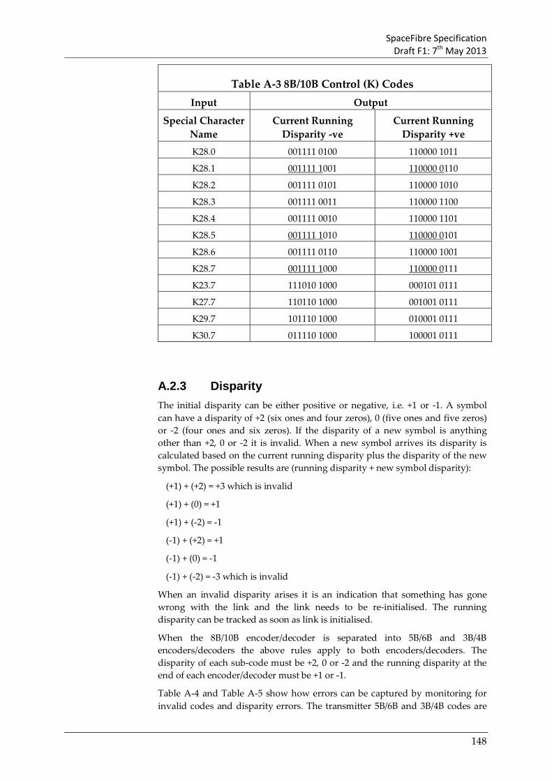
SpaceFibre Specification Draft F1: 7th May 2013
148
Table A-3 8B/10B Control (K) Codes Input Output
Special Character Name
Current Running Disparity -ve
Current Running Disparity +ve
K28.0 001111 0100 110000 1011
K28.1 001111 1001 110000 0110
K28.2 001111 0101 110000 1010
K28.3 001111 0011 110000 1100
K28.4 001111 0010 110000 1101
K28.5 001111 1010 110000 0101
K28.6 001111 0110 110000 1001
K28.7 001111 1000 110000 0111
K23.7 111010 1000 000101 0111
K27.7 110110 1000 001001 0111
K29.7 101110 1000 010001 0111
K30.7 011110 1000 100001 0111
A.2.3 Disparity The initial disparity can be either positive or negative, i.e. +1 or -1. A symbol can have a disparity of +2 (six ones and four zeros), 0 (five ones and five zeros) or -2 (four ones and six zeros). If the disparity of a new symbol is anything other than +2, 0 or -2 it is invalid. When a new symbol arrives its disparity is calculated based on the current running disparity plus the disparity of the new symbol. The possible results are (running disparity + new symbol disparity):
(+1) + (+2) = +3 which is invalid
(+1) + (0) = +1
(+1) + (-2) = -1
(-1) + (+2) = +1
(-1) + (0) = -1
(-1) + (-2) = -3 which is invalid
When an invalid disparity arises it is an indication that something has gone wrong with the link and the link needs to be re-initialised. The running disparity can be tracked as soon as link is initialised.
When the 8B/10B encoder/decoder is separated into 5B/6B and 3B/4B encoders/decoders the above rules apply to both encoders/decoders. The disparity of each sub-code must be +2, 0 or -2 and the running disparity at the end of each encoder/decoder must be +1 or -1.
Table A-4 and Table A-5 show how errors can be captured by monitoring for invalid codes and disparity errors. The transmitter 5B/6B and 3B/4B codes are

SpaceFibre Specification Draft F1: 7th May 2013
149
shown followed by the running disparity (+1 or -1) after the code has been sent. The initial running disparity is -1 in both examples. In Table A-4 a single bit error converts the D00.0 character sent into a code whose 4B component does not appear in the 3B/4B coding table and has a disparity of -4. This is immediately detected as a coding error.
Table A-4 Detection of error by invalid code Character Transmitted Received
D00.0 100111 +1 0100 -1 100111 +1 0000 -3
ERROR
In Table A-5 an error occurs in the first line with the D08.1 character being changed to the D05.1 character. D05.1 is a valid character so goes undetected. The running disparity should however be positive but because of the error it is negative. The characters that follow have neutral disparity so the running disparity remains unchanged and no error is detected. Eventually a character, D15.1, is sent which does not have neutral disparity. At the transmitter the running disparity is negative prior to D15.1 so that character is encoded as 101000 1001 which has negative disparity. When this is received at the receiver the negative disparity causes an error because the running disparity there is already negative. The error has been caught by disparity but several characters were sent before the error became apparent.
The receiver should look out for both invalid characters and disparity errors. It is also important that a CRC code is added to each packet sent to ensure that any error in a packet is detected.
Table A-5 Detection of error by invalid disparity Char Transmitted Received Char D08.1 111001 +1 1001 +1 101001 -1 1001 -1 D05.1
D09.1 100101 +1 1001 +1 100101 -1 1001 -1 D09.1
D10.1 010101 +1 1001 +1 010101 -1 1001 -1 D10.1
D11.1 110100 +1 1001 +1 110100 -1 1001 -1 D11.1
D12.1 001101 +1 1001 +1 001101 -1 1001 -1 D12.1
D13.1 101100 +1 1001 +1 101100 -1 1001 -1 D13.1
D14.1 011100 +1 1001 +1 011100 -1 1001 -1 D14.1
D15.1 101000 -1 1001 -1 101000 -3
ERROR
D15.1

SpaceFibre Specification Draft F1: 7th May 2013
150
A.3 Serialisation and De-Serialisation Serialisation is the conversion of a parallel data stream into a serial one. The parallel 10-bit data word is loaded into a shift register and then shifted out using a transmit clock signal to drive the shift register. A new character has to be loaded into the parallel input of the shift register as soon as the previous 10-bit character has been shifted out to prevent a gap in the serial data.
De-serialisation is the opposite of serialisation. The serial data is shifted into a shift register using a receive clock (also called a bit clock). Recovery of the receive clock from the transmitted serial data stream is described in section A.4 Once a full 10-bit character has been shifted into the shift register it is read out in parallel. The 10-bit character must be read out at the correct point in the serial data stream i.e. when a complete new 10-bit character is in the shift register. Character synchronisation is described in section A.5.
A.4 Receive Clock Recovery Recovery of the receive clock (bit clock) from the received serial data stream is done using a phase-locked loop (PLL). A typical phase-locked loop is shown in Figure A-4.
PhaseDetector Loop Filter
VoltageControlledOscillator
Input Signal(data with
embedded clock)
ReferenceClock
RecoveredBit Clock
PhaseDifference
FilteredControlVoltage
Figure A-4 Typical Phase-Locked Loop The phase of the incoming data stream is compared to the phase of a reference clock signal. The detected phase difference is filtered, removing noise and providing an average phase difference. The filtered phase difference is used to control the frequency of the reference clock. If there is a positive phase difference with edges in the data stream occurring before edges in the reference clock then the reference clock frequency must be increased so that it catches up with the data stream edges. If there is a negative phase difference then the reference clock is occurring too early so must be slowed down, in which case the reference clock frequency is reduced.
When locked so that there is no phase difference, the reference clock can be used to recover the data-bits from the serial stream.
High frequency phase locked loops are normally implemented using a voltage controlled oscillator and an analogue loop filter.

SpaceFibre Specification Draft F1: 7th May 2013
151
The time taken for a PLL to lock onto a signal is dependent upon the design of the PLL and the difference between the input bit stream phase and the PLL reference clock phase. Typically it takes at least 5000 edges in the bit stream for a PLL to lock although it can be substantially longer for some PLL designs.
A.5 Symbol Synchronisation Symbol synchronisation is necessary in the receiver to separate out each symbol from the received bit stream. To do this is it necessary to identify where a symbol starts, after that each individual symbol can be separated by simply counting 10-bits for each symbol. Identifying the start of a symbol is used using the 8B/10B Comma bit sequences. Comma sequences are unique seven bit sequences:
• Plus Comma 0011111
• Negative Comma 1100000
An illustration of symbol synchronisation using a plus comma is shown in Figure A-5. The start of the next character occurs on the fourth bit after the end of the detected plus comma.
01001100111110010101011100
CommaStart of Symbol
Figure A-5 Symbol Synchronisation Using a Plus Comma Note that SpaceFibre uses all 10-bits of the commas for symbol synchronisation, rather than just 7-bits.
There are two principal means of performing symbol synchronisation. The first method, shown in Figure A-6, performs the symbol synchronisation after de-serialisation, while the second method, illustrated in Figure A-7, does it during de-serialisation.
Figure A-6 shows the received bit stream being fed into the de-serialising shift register. As soon as ten bits have been received the de-serialised data is loaded into a register. The exact position of the ten bits in the data stream is not important. After a further ten bits have been received the data in the register is loaded into a second register and the de-serialised data is loaded into the first register. The 20 bits in these two registers are examined for a possible comma, using the comma detect circuitry. The combinatorial logic in the comma detect circuitry outputs a Comma Detect signal when a comma is found and registers the position of the start of the next character. The Start of Symbol is used to drive a 20:10 multiplexer which select the ten-bits of a character from the 20-bits in the two registers.
With this approach comma detection is done at a clock rate of one tenth of that of the bit stream. The comma detect circuitry has to simultaneously look for a comma in ten possible bit positions, requiring 10 correlators.

SpaceFibre Specification Draft F1: 7th May 2013
152
DeserialiserBit Stream
Register
Register
20:10 Mux
CommaDetect10 10
Aligned 10B Code
Start ofSymbol
CommaDetect
Bit Clock DivideBy 10
Figure A-6 Symbol Alignment After De-serialisation The other approach, shown in Figure A-7, performs comma detection at the bit clock rate. The bit stream is fed into a 10-bit shift register (de-serialiser). The 10-bit parallel output from the shift register fed to a 10-bit character register and to a Comma Detect circuit. The Comma Detect circuit looks for a Comma in the last seven bits of the shift register (i.e. the first seven bits to enter the shift register). When a comma is detected the data in the shift register are loaded into the data register. A bit counter is used to count the 10-bits in each character, loading the data register from the shift register every 10 bits. The comma detect circuit resets the counter, re-synchronising the bit counter and forcing the data in the shift register to be loaded into the data register.
This approach requires the comma detect circuitry to operate at the rate of the bit clock and needs a high-speed bit counter. The amount of circuitry is significantly less that the other approach.

SpaceFibre Specification Draft F1: 7th May 2013
153
DeserialiserBit Stream
Register
CommaDetect
Aligned 10B Code
Start ofCharacter
CommaDetect
Bit Counter
Reset
Bit Clock
Figure A-7 Character Alignment During De-serialisation
A.6 Receive Elastic Buffer The two ends of a link are both expected to operate at the same frequency. In practice, however, there will be slight differences in the clocks at the two ends of the link. This can cause receive buffer overflow or under-run problems unless the difference in the two clock speeds is compensated for. This is achieved using a Receive Elastic Buffer and associated SKIP characters.
The receive clock (bit clock) is recovered from the incoming bit stream, so is at the same frequency as the transmit clock at the other end of the link. After de-serialisation and character synchronisation the incoming data must be transferred from the receive clock domain to the local system clock domain. In passing between these two clock domains, slight differences in the clock frequencies must be accommodated. This is achieved using the Receive Elastic Buffer.
The normal situation with a Receive Elastic Buffer is illustrated in Figure A-8. Data is written into the buffer using a write pointer which operates at the receive character rate (RXRECCLK). It is read out by read pointer which operates at the user system character rate (RXUSRCLK).
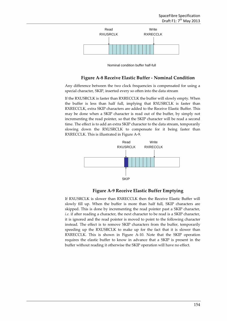
SpaceFibre Specification Draft F1: 7th May 2013
154
ReadRXUSRCLK
WriteRXRECCLK
Nominal condition buffer half-full
Figure A-8 Receive Elastic Buffer - Nominal Condition Any difference between the two clock frequencies is compensated for using a special character, SKIP, inserted every so often into the data stream
If the RXUSRCLK is faster than RXRECCLK the buffer will slowly empty. When the buffer is less than half full, implying that RXUSRCLK is faster than RXRECCLK, extra SKIP characters are added to the Receive Elastic Buffer. This may be done when a SKIP character is read out of the buffer, by simply not incrementing the read pointer, so that the SKIP character will be read a second time. The effect is to add an extra SKIP character to the data stream, temporarily slowing down the RXUSRCLK to compensate for it being faster than RXRECCLK. This is illustrated in Figure A-9.
ReadRXUSRCLK
WriteRXRECCLK
SKIP
Figure A-9 Receive Elastic Buffer Emptying
If RXUSRCLK is slower than RXRECCLK then the Receive Elastic Buffer will slowly fill up. When the buffer is more than half full, SKIP characters are skipped. This is done by incrementing the read pointer past a SKIP character, i.e. if after reading a character, the next character to be read is a SKIP character, it is ignored and the read pointer is moved to point to the following character instead. The effect is to remove SKIP characters from the buffer, temporarily speeding up the RXUSRCLK to make up for the fact that it is slower than RXRECCLK. This is shown in Figure A-10. Note that the SKIP operation requires the elastic buffer to know in advance that a SKIP is present in the buffer without reading it otherwise the SKIP operation will have no effect.

SpaceFibre Specification Draft F1: 7th May 2013
155
ReadRXUSRCLK
WriteRXRECCLK
SKIP
Figure A-10 Receive Elastic Buffer Filling Up For the Receive Elastic Buffer to work properly there must be sufficient SKIPs in the data stream, so that they can be remove if necessary. The frequency of SKIPs depends on the size of the elastic buffer and the maximum frequency difference between RXUSRCLK and RXRECCLK.
Assume that the nominal operational frequency is F symbols per second and that the maximum clock difference, is D Hz, then the time, T, taken for the elastic buffer to have one symbol too many or one symbol too few is given by:
T = 1 / (Receive Clock Frequency – User Clock Frequency)
T = 1/ ( (F+D) – (F-D) )= 1/ (2D)
In this time the number of symbols sent is
N = (F+D).T
which is approximately
N ≈ F/(2D)
since F is much greater than D.
Now D/F is the maximum clock drift, so
N ≈ 1/(2P)
Where P is the maximum drift in the clock.
For a ±100 ppm maximum clock drift, which is readily achievable using crystal oscillators, D, is 10-4, and the number of symbols sent before the elastic buffer is one symbol out is 5000. A SKIP symbol must thus be sent every 5000 symbols to prevent the Elastic buffer from ever being more than one symbol out. This is the case independent of the size of the symbols.
In SpaceFibre the receive elastic buffer stores control and data words rather than individual symbols. The SKIP control word is therefore four symbols lone, i.e. one word long.

SpaceFibre Specification Draft F1: 7th May 2013
156
Annex B (informative) Example of SpaceFibre CRC
implementation
B.1 Overview In this example implementations of the CRC used by SpaceFibre are provide in VHDL and C-code.
B.2 VHDL implementation of SpaceFibre CRC

SpaceFibre Specification Draft F1: 7th May 2013
157
Bibliography
ECSS-ST-S-00 ECSS system - Description, implementation and general requirements
ECSS-E-ST-50 Space engineering - Communications
ECSS-E-HB-50 Space engineering - Communications guidelines
ECSS-E-ST-40 Space engineering - Software
http://www.spacewire.esa.int SpaceWire website