Embed Size (px)
Citation preview

IST-2003-511598 (NoE)
COGAIN
Communication by Gaze Interaction
Network of Excellence
Information Society Technologies
D5.3 Eye Tracking Hardware Issues
Due date of deliverable: 28.02.2007 Actual submission date: 04.04.2007
Start date of project: 1.9.2004 Duration: 60 months Siauliai University
Project co-funded by the European Commission within the Sixth Framework Programme (2002-2006) Dissemination Level
PU Public x PP Restricted to other programme participants (including the Commission Services) RE Restricted to a group specified by the consortium (including the Commission Services) CO Confidential, only for members of the consortium (including the Commission Services)
Communication by Gaze Interaction (COGAIN), IST-2003-511598
04.04.2007 1/47
Daunys G., Böhme, M., Droege, D., Villanueva, A., Delbrück, T., Hansen, D.W., Stepankova, O., Ramanauskas, N., and Kumpys, L. (2007) D5.3 Eye Tracking Hardware Issues. Communication by Gaze Interaction (COGAIN), IST-2003-511598: Deliverable 5.3. Available at http://www.cogain.org/results/reports/COGAIN-D5.3.pdf Contributors: Gintautas Daunys (SU)
Martin Böhme (UzL) Detlev Droege (UNI KO-LD) Arantxa Villanueva (UPNA) Tobi Delbrück (UNIZH) Dan Witzner Hansen (ITU, DTU) Olga Stepankova (CTU) Nerijus Ramanauskas (SU) Laimonas Kumpys (SU)

Communication by Gaze Interaction (COGAIN), IST-2003-511598
04.04.2007 2/47
Table of Contents
EXECUTIVE SUMMARY.......................................................................................................................................................... 4
1 INTRODUCTION ................................................................................................................................................................ 5 1.1 Eye tracker components............................................................................................................................................ 5 1.2 Objectives of the deliverable ..................................................................................................................................... 6
2 CAMERAS FOR EYE TRACKING..................................................................................................................................... 7 2.1 Classes of cameras................................................................................................................................................... 7 2.2 Image sensor............................................................................................................................................................. 8 2.3 Spectral sensitivity..................................................................................................................................................... 9 2.4 Resolution and frame rate ....................................................................................................................................... 13 2.5 Interface .................................................................................................................................................................. 15
2.5.1 Analogue camera standards......................................................................................................................... 15 2.5.2 USB .............................................................................................................................................................. 16 2.5.3 Firewire (IEEE-1394) .................................................................................................................................... 17 2.5.4 Camera Link ................................................................................................................................................. 17 2.5.5 Gigabit Ethernet............................................................................................................................................ 17
2.6 Recommendations for camera selection ................................................................................................................. 18
3 OPTICAL SYSTEMS........................................................................................................................................................ 19 3.1 Lens parameters ..................................................................................................................................................... 19
3.1.1 Lens focal length and magnification ............................................................................................................. 19 3.1.2 F-number and image depth .......................................................................................................................... 20
3.2 Other lens parameters............................................................................................................................................. 21 3.3 Calibration distortion models ................................................................................................................................... 22
4 OTHER COMPONENTS FOR GAZE TRACKERS.......................................................................................................... 24 4.1 Lighting.................................................................................................................................................................... 24 4.2 Camera mounting systems...................................................................................................................................... 24
4.2.1 Eagle MotorPod............................................................................................................................................ 24 4.2.2 Indoor Pan/Tilt unit ....................................................................................................................................... 25 4.2.3 Directed Perception model PTU-D46 ........................................................................................................... 25 4.2.4 Edmund Optics articulated arm .................................................................................................................... 25
4.3 Ultrasonic range finders .......................................................................................................................................... 25
5 EYE TRACKING USING ADI BLACKFIN PROCESSORS ............................................................................................. 27 5.1 Architecture of ADI Blackfin processors .................................................................................................................. 27 5.2 uClinux .................................................................................................................................................................... 28 5.3 Results .................................................................................................................................................................... 29
6 EYE TRACKER LAYOUT SIMULATION AND EXPERIMENTAL RESULTS................................................................. 30 6.1 Simulation framework.............................................................................................................................................. 30
6.1.1 Introduction................................................................................................................................................... 30 6.1.2 Geometric conventions................................................................................................................................. 30 6.1.3 A Short example ........................................................................................................................................... 31 6.1.4 Functions ...................................................................................................................................................... 33

Communication by Gaze Interaction (COGAIN), IST-2003-511598
04.04.2007 3/47
7 DEVELOPED SYSTEMS ................................................................................................................................................. 34 7.1 UzL.......................................................................................................................................................................... 34 7.2 UNI KO-LD .............................................................................................................................................................. 35 7.3 SU ........................................................................................................................................................................... 36 7.4 UPNA ...................................................................................................................................................................... 36 7.5 UNIZH ..................................................................................................................................................................... 38 7.6 CTU......................................................................................................................................................................... 39
8 REFERENCES ................................................................................................................................................................. 40
APPENDIX A: MANUFACTURERS OF CAMERAS WITH FIREWIRE (IEEE-1394) INTERFACE ...................................... 42
APPENDIX B: MAIN MANUFACTURERS OF LENSES ....................................................................................................... 45
APPENDIX C: INTERNET SHOPS FOR HARDWARE COMPONENTS .............................................................................. 46
APPENDIX D: USEFUL LINKS.............................................................................................................................................. 47

Communication by Gaze Interaction (COGAIN), IST-2003-511598
04.04.2007 4/47
Executive Summary
This deliverable is about hardware for eye tracking. The eye tracker and its main components are analysed in Section 1. The video cameras and their main parameters are described in Section 2. The key component of a camera is its image sensor, which properties significantly influence the camera properties. Another important issue is the camera’s connectivity to a computer because a big amount of information must be transferred from the image sensor to the computer. Section 3 is devoted to the optical system of an eye tracker. Finding of a compromise between the large zoom of the eye image and the depth of image is also an important issue. The optical system must ensure good focusing of the eye, despite that it moves. Most state of the art systems use infrared lighting. Possible sources of infrared lighting are described in Section 4. Here, the camera mounting and easy orientation issues are also discussed. Ways of creating portable eye trackers are analysed in Section 5. Application of Analog Devices Blackfin DSP processors and uClinux operation system are analysed in this section. A framework for eye tracker hardware simulation is presented in Section 6. Mathworks Matlab implementation developed at University of Lübeck is available for download from COGAIN website. Finally, the eye tracking systems developed at the COGAIN partner institutions are described in Section 7.

Communication by Gaze Interaction (COGAIN), IST-2003-511598
04.04.2007 5/47
1 Introduction
An eye tracker is a device for measuring angular eye position. Only a few years ago the standard in eye tracking was for systems to be intrusive, i.e. they either required the user’s head to be fixated or the equipment to be mounted on the user’s head. Systems have now evolved to the point where the user is allowed much more freedom in head movements while maintaining good accuracy (1 degree or better). For example, electro-oculography (EOG) was a popular method forty years ago. This type of system measures the potential differences at specific points of the skin around the eye via electrodes. Movements of the eye inside its orbit cause signal variations. While EOG systems produce good results, intrusiveness and lack of handling head movements are among their limitations. Bite bars and head-mounted eye trackers have previously been used since they, by construction, minimize head movements relative to the camera observing the user. These methods implicitly assume that an observed pupil position change corresponds to a fixed gaze change relative to the head. The results obtained with these kinds of systems seem to be satisfactory when it comes to accuracy. Despite the effort involved in constructing more comfortable head mounted systems, less invasive techniques are obviously desirable. The ideal in this respect would be an eye tracker with a minimal degree of invasion, allowing relatively free head movement while maintaining high accuracy. The last few years have seen the development of so called remote eye trackers, which do not require the user to wear helmets nor to be fixated. Instead, the systems employ strategies using one or several cameras, with possible use of external light sources emitting invisible light (infrared - IR) on the user. The light sources produce stable reflections on the surface of the eye, which are observable in the images. The first remote eye tracking systems that appeared in the literature used multiple cameras (Shih et al, 2000; Beymer and Flickner, 2003; Ohno and Mukawa, 2004; Brolly and Mulligan, 2004; Yoo and Chung, 2005), usually in some kind of stereo setup. The first single camera remote eye tracker with high accuracy (0.5 to 1 degree) and a good tolerance to user movement was a commercial system (Tobii 2002), but implementation details have not been made available. Recently, several academic groups have built similar single-camera systems (Hennessey et al., 2006; Guestrin and Eizenman, 2006; Meyer et al., 2006). Guestrin and Eizenman’s system (2006) allows only small head movements, but it appears that their well-founded approach would allow greater head movements with a higher-resolution camera. The advantage of a single-camera system is of course the reduced cost and smaller size. In the following sections we will detail the underlying models used to infer gaze based on the use of image data and the possible knowledge of the system geometry. We will merely focus on eye trackers based on video (a.k.a. video occulography) and with a special emphasis on eye trackers that extract features such as the reflections and centre of the pupil for gaze estimation.
1.1 Eye tracker components An eye tracker consists of several parts; a general overview of these is provided in Figure 1. A video-based eye tracker obtains its information from one or more cameras (Image Data). The first step of an eye tracker is to find the initial eye position (Detection component) in the images. The position is used for initializing the Eye Tracking component, which, in turn, aims at following the eye over time. Based on information obtained from the eye region and possibly head pose, the Gaze Estimation component will then determine where the user is looking. This information is then used in the gaze-based application. The objective is to review all possible feature combinations and to evaluate the ability of the resulting models to estimate gaze.

Communication by Gaze Interaction (COGAIN), IST-2003-511598
04.04.2007 6/47
Figure 1. Eye tracker components
Eye tracker software components were analysed in deliverable D5.2 “Report on new approaches to Eye Tracking” (Daynys et al. 2006). The focus of the current deliverable is mainly on the hardware components of the system. The hardware components must ensure good quality image data with required features such as the eye pupil and the glints produced by infrared light sources. The main hardware component of an eye tracker is the camera.
1.2 Objectives of the deliverable The aim of deliverable is provide information about hardware components of an eye tracker. First, a designer must choose a camera for image acquisition. A camera is characterised by a set of parameters such as the sensor type, interface, frame rate, resolutions and others. The way how to achieve the best compromise between features of camera and its price is one of the objectives. Next important component, which can be considered separately from camera, is its optical system. Lenses are also described by a set of parameters e.g. focal distance, F-number, aberrations. In eye tracker lenses must ensure high quality image of eye, i.e. optimal magnification, minimal blur, and minimal geometrical distortions. Other components also are needed for eye tracker design. For example: light sources for glint formation; and systems for camera mounting and adjusting its orientation in relation to the user’s eye.

Communication by Gaze Interaction (COGAIN), IST-2003-511598
04.04.2007 7/47
2 Cameras for Eye Tracking
A camera is a key hardware component of an eye tracker. Other technical solutions are mainly influenced by the choice of a camera. The camera’s technical properties have considerable impact on the performance and stability of the employed algorithms. Furthermore, the influence of several external conditions, e.g. lighting conditions, can be minimized by a proper choice. The aim of the current section is to share information between partners about good practice and provide criteria for camera selection.
2.1 Classes of cameras Majority of cameras on market can be classified into 5 classes:
• machine vision cameras; • CCTV (Closed Circuit Television) cameras; • webcams; • camcorders; • digital still cameras.
Machine vision cameras are developed for video data transfer to computer for further data analysis by machine vision algorithms. Machine vision cameras have big variety because of different frame rate, resolution, connectivity, image sensor type, spectral response. Functionally machine vision cameras are most suitable for eye tracking, as they transfer uncompressed digital data. A disadvantage is the high price of such cameras. CCTV cameras are mainly used in surveillance systems. They deliver analogue video signal by NTSC, PAL or SECAM standard. Analogue signal can be transferred by long cables to monitor or writing devices. Because the target is visual output, CCTV cameras deliver interlaced frames by frame rate of 30 or 25 fps (frames per second). Most CCTV cameras operate in low light conditions. They have sensitive sensors. Some cameras are optimised for near infrared range. The last two features are attractive for eye tracking. Also price are lower than for machine vision cameras. Webcams were introduced recently. Their purpose is deliver video information through Internet in real time. Most of web cameras have frame rate of 30 fps. To reduce the data transfer volume, they deliver compressed video data. Webcams have built in optical lenses. Inside the cameras there are colour response image sensors. Infrared light is an artefact for webcams. Usually they have filters to remove infrared illumination. Functionally webcams are not the best choice for eye tracking. Attractive features include low price, digital output with (fully available for most PC’s) USB connectivity. Camcorders are portable devices for recording video images on an internal storage device. Nowadays camcorders are digital. Some of them could be used as webcams. Their benefit against webcams is a better optical system with a possibility of optical zooming. Sony camcorders also have “Night Vision” function. In this regime a built in infrared light source is used for scene lighting. Most camcorders also have Firewire (i-Link for Sony camcorders) connectivity, which has advantages compared with USB. Though the prices for camcorders are significantly higher than for webcams, camcorders are more preferable for eye tracking than webcams because of the above mentioned features. A disadvantage, as for most of all cameras, is the (low) frame rate of NTSC or PAL video.
Communication by Gaze Interaction (COGAIN), IST-2003-511598
04.04.2007 8/47
Digital still cameras are devices used to capture and to store photographs in a digital format. More advanced cameras also have a video function. The benefit of still cameras is their higher resolution combined with high quality optics. However, the benefit invokes a disadvantage: a lower frame rate as for camcorders.
2.2 Image sensor Every camera, which in real time can be connected to a computer, has the following elements:
• optical system; • image sensor; • interface circuit.
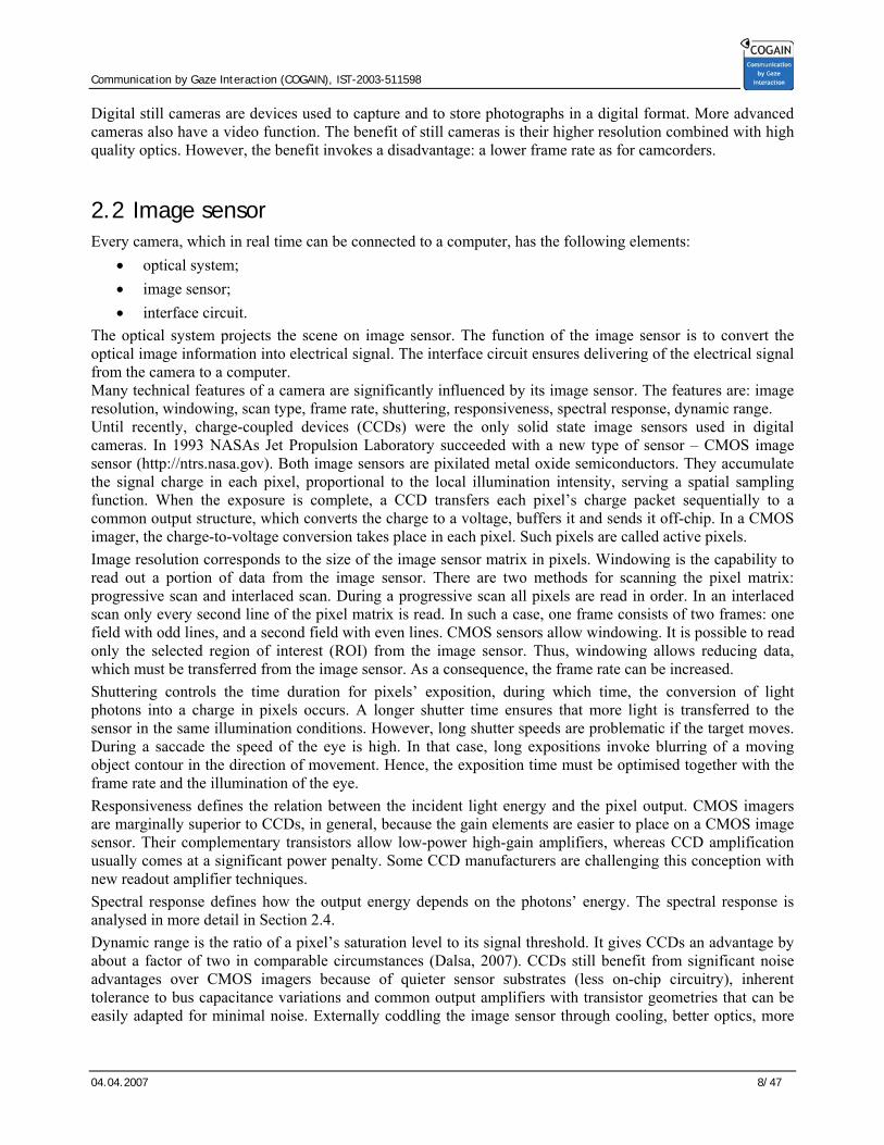
The optical system projects the scene on image sensor. The function of the image sensor is to convert the optical image information into electrical signal. The interface circuit ensures delivering of the electrical signal from the camera to a computer. Many technical features of a camera are significantly influenced by its image sensor. The features are: image resolution, windowing, scan type, frame rate, shuttering, responsiveness, spectral response, dynamic range. Until recently, charge-coupled devices (CCDs) were the only solid state image sensors used in digital cameras. In 1993 NASAs Jet Propulsion Laboratory succeeded with a new type of sensor – CMOS image sensor (http://ntrs.nasa.gov). Both image sensors are pixilated metal oxide semiconductors. They accumulate the signal charge in each pixel, proportional to the local illumination intensity, serving a spatial sampling function. When the exposure is complete, a CCD transfers each pixel’s charge packet sequentially to a common output structure, which converts the charge to a voltage, buffers it and sends it off-chip. In a CMOS imager, the charge-to-voltage conversion takes place in each pixel. Such pixels are called active pixels. Image resolution corresponds to the size of the image sensor matrix in pixels. Windowing is the capability to read out a portion of data from the image sensor. There are two methods for scanning the pixel matrix: progressive scan and interlaced scan. During a progressive scan all pixels are read in order. In an interlaced scan only every second line of the pixel matrix is read. In such a case, one frame consists of two frames: one field with odd lines, and a second field with even lines. CMOS sensors allow windowing. It is possible to read only the selected region of interest (ROI) from the image sensor. Thus, windowing allows reducing data, which must be transferred from the image sensor. As a consequence, the frame rate can be increased. Shuttering controls the time duration for pixels’ exposition, during which time, the conversion of light photons into a charge in pixels occurs. A longer shutter time ensures that more light is transferred to the sensor in the same illumination conditions. However, long shutter speeds are problematic if the target moves. During a saccade the speed of the eye is high. In that case, long expositions invoke blurring of a moving object contour in the direction of movement. Hence, the exposition time must be optimised together with the frame rate and the illumination of the eye. Responsiveness defines the relation between the incident light energy and the pixel output. CMOS imagers are marginally superior to CCDs, in general, because the gain elements are easier to place on a CMOS image sensor. Their complementary transistors allow low-power high-gain amplifiers, whereas CCD amplification usually comes at a significant power penalty. Some CCD manufacturers are challenging this conception with new readout amplifier techniques. Spectral response defines how the output energy depends on the photons’ energy. The spectral response is analysed in more detail in Section 2.4. Dynamic range is the ratio of a pixel’s saturation level to its signal threshold. It gives CCDs an advantage by about a factor of two in comparable circumstances (Dalsa, 2007). CCDs still benefit from significant noise advantages over CMOS imagers because of quieter sensor substrates (less on-chip circuitry), inherent tolerance to bus capacitance variations and common output amplifiers with transistor geometries that can be easily adapted for minimal noise. Externally coddling the image sensor through cooling, better optics, more

Communication by Gaze Interaction (COGAIN), IST-2003-511598
04.04.2007 9/47
resolution or adapted off-chip electronics still cannot make CMOS sensors equivalent to CCDs in this regard. The dynamic range can be defined in decibels or effective number of bits. The parameter causes number of output bits for pixel; usually it is 8, 10, or 12. An important image sensor parameter for selecting the optical system is the sensor’s format because lens must produce image of approximately the same size. Format is evaluated from the sensor width. There are formats of sensors of 1”, 2/3”, 1/2”, 1/3”, 1/4”, and 1/6”. Their geometrical size is given in Table 2.1.
Sensor format Height, mm Width, mm
1” 9.6 12.8
2/3” 6.6 8.8
1/2” 4.8 6.4
1/3” 3.6 4.8
1/4” 2.4 3.2
1/6” 1.8 2.4
Table 2.1. Geometrical size of image sensors
2.3 Spectral sensitivity In general, any spectral domain could be used for gaze detection. However, these domains severely influence the methods which can be used. Almost all image sensors (except some infrared sensors for thermovisors) are made on silicon basis. Photosites of sensor are sensitive to all light wave lengths of visual range and also in near ultraviolet and near infrared. Silicon based image sensors are sensitive to light with wavelengths up to 1050 nm. Sensitivity to light other, as of visible range, is an artefact for consumer cameras. To filter out unwanted artefacts, COTS (commercial off-the-self) cameras often come with coated lenses, limiting the bandwidth to the visible light spectrum. Most of the CCD cameras on market today are using Super HAD technology. Super HAD will provide two times better sensitivity and six db better smear rejection ratio than the former, old type CCD. Two micro lenses on top of each photo diode will collect more photons from incoming light than the old CCD made by SONY or any other manufacturer. Spectral response of Sony ICX059CL sensor, based on Super HAD technology, is shown in Figure 2.2.

Communication by Gaze Interaction (COGAIN), IST-2003-511598
04.04.2007 10/47
Figure 2.2. Relative spectral response of Sony ICX059CL sensor (Sony Global, 2007) Sensitivity to near infrared light is useful for security applications, in low light conditions. To increase sensitivity in near infrared zone, SONY invented the Ex-View technology. The spectral response of the Sony sensor with Ex-View technology ICX428ALLis shown in Figure 2.3. Sony Ex-view CCD have 2-3 times better sensitivity on near infrared zone ( 800~ 900 nm) compare to Super HAD.
Figure 2.3. Relative spectral response of Sony ICX428ALL sensor (Sony Global, 2007)
Basler A601f, A602f, A622f cameras have CMOS image sensors. Their quantum efficiency characteristics are shown in Figure 2.4. Common features of all sensors are that they are sensitive to near infrared light. On the other hand, their sensitivity is significantly lower in infrared region to compare with 500-600 nm region.

Communication by Gaze Interaction (COGAIN), IST-2003-511598
04.04.2007 11/47
Figure 2.4. Quantum efficiency of Basler A601f/A602f cameras – yellow, A622f – blue (Basler, 2007) By form of spectral characteristic high sensitivity in infrared region has Kodak sensor 9618, which spectral characteristic is shown in Figure 2.5.
Figure 2.5 Spectral response of Kodak 9618 sensor (Kodak, 2007)
The colour image sensor has a Bayer filter on a grid of photosensors. Bayer filter is a colour filter array to separate red, green and blue components from full waves range. The term derives from the name of its inventor, Dr. Bryce E. Bayer of Eastman Kodak. The filter pattern is: 50% green, 25% red and 25% blue, hence it is also called RGBG or GRGB. An example of the filter is shown in Figure 2.6.

Communication by Gaze Interaction (COGAIN), IST-2003-511598
04.04.2007 12/47
Figure 2.6. Bayer filter of colour image sensor
This implies that for using the corneal reflection method, visible light sources have to be used. These, however, might blind the user and cause fatigue to the eye. As a consequence, the majority of COTS cameras are not suitable for the corneal reflection method, but require separate eye and head pose estimation. While using colour information to detect the position of the head is helpful, Bland and white (B&W) cameras could be used as well. However, if no dedicated light source is present in the system, the setup highly suffers from varying environmental lighting conditions. Using cameras without an IR limiting coating offers the possibility to use IR lights for the corneal reflection method, as IR lights are not visible to the user. Spectral characteristics suggest that for IR light it is better to use an IR LED, which emits light more close to visible region. The GaAsAl IR emitting diodes are most suitable, because they produce light of 880 nm. Spectral response near 880 nm wavelength is important. From spectral characteristics we obtain that quantum efficiency is 5-10 times smaller than at the maximum. Best image sensors seem are Sony Ex-View technology sensors, listed in Table 2.2.
Sensor Image size (type)
TV system
Effective pixels (H x V)
Sensitivity Typ. (mv)
ICX428ALL 1/2 EIA 768 x 494 1,400
ICX428ALB 1/2 EIA 768 x 494 1,400
ICX429ALL 1/2 CCIR 752 x 582 1,400
ICX429ALB 1/2 CCIR 752 x 582 1,400
ICX254AL 1/3 EIA 510 x 492 1,600
ICX255AL 1/3 CCIR 500 x 582 1,600
ICX258AL 1/3 EIA 768 x 494 1,000
ICX259AL 1/3 CCIR 752 x 582 1,000
ICX278AL 1/4 EIA 768 x 494 800
ICX279AL 1/4 CCIR 752 x 582 800
Table 2.2. Black and white image sensors with Ex-view CCD technology from Sony (Sony Global 2007)

Communication by Gaze Interaction (COGAIN), IST-2003-511598
04.04.2007 13/47
2.4 Resolution and frame rate The quality of a digital image depends in part on the number of pixels used to create the image. The maximum number that one can capture depends on how many pixels there are on the image sensor used to capture the image. Resolution can be of two kinds: optical and interpolated. The optical resolution of a camera is an absolute number because an image sensor's pixels are physical entities that can be counted. To improve resolution in certain limited respects, the resolution can be increased using software. This process, called interpolated resolution, adds pixels to the image. To do so, software evaluates those pixels surrounding each new pixel to determine what its colours should be. What's important to keep in mind is that interpolated resolution doesn't add any new information to the image—it just adds pixels and makes the file larger. Interpolation is often used for coloured images. An example is given in Figure 2.7 (Micron 2007). The next algorithm is used:
• Have blue, need green and red. G= average of 4 neighbouring greens. R= average of 4 neighbouring reds.
• Have green, need blue and red. B= average of 2 neighbouring blues. R= average of 2 neighbouring reds.
• Have red, need green and blue. G= average of 4 neighbouring greens. B= average of 4 neighbouring blues
Figure 2.7 Interpolation of pixels (Micron, 2007) More pixels add detail and sharpen edges. If any digital image is enlarged enough, the pixels will begin to show-an effect called pixelization. The more pixels there are in an image, the more it can be enlarged before pixelization occurs. Although better resolution often means better images, increasing of photosites matrix isn't easy and creates other problems. For example:
• It adds significantly more photosites to the chip so the chip must be larger and each photosite smaller. Larger chips with more photosites increase difficulties (and costs) of manufacturing. Smaller photosites must be more sensitive to capture the same amount of light.
• Bigger resolution image needs more data bytes to store or transfer. This is illustrated in Table 2.3.

Communication by Gaze Interaction (COGAIN), IST-2003-511598
04.04.2007 14/47
Abbreviation Name Width, pixels
Height, pixels
Number of pixels
Needed data rate, Mbs
QCIF Quarter Common Intermediate Format 176 144 25,300 6.07
QVGA Quarter Video Graphics Array 320 240 76,800 18.43
CIF Common Intermediate Format 352 288 101,400 24.34
VGA Video Graphics Array 640 480 307,200 73.73
MPEG2 ML MPEG2 Main Level 720 576 414,720 99.53
SVGA Super Video Graphics Array 800 600 480,000 115.20
XGA Extended Graphics Array 1024 768 786,400 188.74
1.3 megapixel 1280 1024 1,310,720 314.57
2-megapixel 1600 1200 1,920,000 460.80
Table 2.3. Cameras resolutions and needed data rate to transfer data with frame rate 30 fps Some assumptions have to be made to narrow the choice of possible hardware setups. They were made with a “usual” user setup in mind that is an ordinary desktop or portable computer as a base. Most users have a normal distance of 35-50 cm between their head and the computer monitor. During work, they do move the head vertically and horizontally and might also rotate their head by some amount. The head motion is small enough (+/- 15 cm horizontally, +/- 10 cm vertically) to use a camera with fixed focal length if chosen appropriate. This limitation does however enforce a minimum resolution of the camera of 640x480 pixels to achieve usable results. We show the resulting image of an eye taken with a 1/3 inch camera chip at a resolution of 720x576 pixels, equipped with an 8mm lens, at a distance of approximately 40 cm in Figure 2.8.
Figure 2.8. Zoomed in of the eye taken with a 720x576 camera, 8mm lens at 40cm
The size of approx. 26 pixels diameter for the iris and approx. 7 pixels for the pupil in this example show the minimum resolution to do a sufficiently accurate image processing. The reflection of two windows (middle left and right in the iris) and of a infrared light (lower middle) can be distinguished.

Communication by Gaze Interaction (COGAIN), IST-2003-511598
04.04.2007 15/47
Eye movements tend to be very rapid, as well as short head movements. To take advantage of successive frames, a sufficiently high frame rate is required. Tests showed 12 fps to be too slow, while good results were achieved at 25 fps. To avoid the localisation of the eyes in every frame, information from the preceding frames is used to estimate the position in the current frames. This considerably reduces the CPU load as opposed to a complete search for every frame. Thus, the higher demands for processing at a larger frame rate are easily compensated by the gain achieved from looking into the past.
2.5 Interface The connection of the camera to the computer also has to be considered. With current computers, the use of USB cameras seems to be the method of choice, as numerous models are available and every current computer is equipped with USB connectors. Alternatively, a FireWire connection (IEEE 1394) or standard frame grabber hardware for analogous cameras could be used.
2.5.1 Analogue camera standards1 CCIR The CCIR is a standards body that originally defined the 625 line 25 frames per second TV standard used in many parts of the world. The CCIR standard defines only the monochrome picture component, and there are two major colour encoding techniques used with it, PAL and SECAM. The CCIR standard uses 1:2 interlace which means that each 625 line TV image is composed from 2 video fields, each consisting of 312 lines of picture information. The first video field contains just the odd numbered lines from the 625 line picture, the second field contains just the even ones. CCIR video format is the format used is the European Broadcast Standard. The picture has 582 lines and uses interlacing. Horizontal sync rates of 15625 Hz and field rate of 50 Hz. CCIR electrical signal is 75 ohm system and 1.0V volt (peak-to-peak, including sync) signal. Here is some data of CCIR video signal:
Line period 64 us (Micro-seconds) Line blanking 12.05 +- 0.25 us Line sync 4.7 +- 0.1 us Front porch: 1.65 +- 0.1 us
For color television (PAL standard) the following extra details were defined: Color burst start 5.6 +- 0.1 us after sync start. Color burst 10 +- 1 cycles Color sub carrier 4.433 MHz
RS-170 standard The EIA (Electronic Industry Association) is the standards body that originally defined the 525 line 30 frame per second TV standard used in North America, Japan, and a few other parts of the world. The EIA standard, also defined under US standard RS-170A, defines only the monochrome picture component but is mainly
1 Section reference: RS-170 Video signal (by T. Engdahl) http://www.epanorama.net/documents/video/rs170.html
Communication by Gaze Interaction (COGAIN), IST-2003-511598
04.04.2007 16/47
used with the NTSC colour encoding standard, although a version which uses the PAL colour encoding standard does also exist. An RS-170 video frame contains 525 lines and is displayed 60 times per second for a total of 15,750 lines, or 15.75 KHz. Of these lines, only the odd or even lines are displayed with each frame. A total of 60 frames per second allows 30 frames per second, or a 30-Hz update of each line. RS-170 was the original "black-and-white" television signal definition, per EIA. The original standard defined a 75 ohm system and a 1.4 volt (peak-to-peak, including sync) signal. Signal level specifications form RS-170 were:
White: +1.000 V Black: +0.075 V Blank: (0V reference) Sync: - 0.400 V
Nowadays RS-170 details are quite much in use, although the nominal signal level used nowadays is generally 1.0V (peak to peak). This 1.0V level was adopted from RS-343 standard to video industry. Black and white (monochrome) cameras are the simplest. They have single output cable which carries an RS-170 video signal. RS-170 signals are usually transferred using coaxial cable connected to BNC or RCA connectors. Frame grabber hardware needs to be employed to connect cameras emitting a classical analogue signal. They transform this signal to a digital image frame by frame, which is then supplied to the system. These cards need to be installed into the system, either as a PCI extension card for desktop computers or as pluggable “PC-Cards” for notebooks. They are usually limited to the resolution of standard TV (e.g. 720x576 for PAL). As they are directly connected to the internal system bus they don't need to compress the images, thus avoiding compression artefacts.
2.5.2 USB2 USB was designed from the ground up to be an interface for communicating with many types of peripherals without the limits and frustrations of older interfaces. Every recent PC and Macintosh computer includes USB ports that can connect to standard peripherals such as keyboards, mice, scanners, cameras, printers, and drives as well as custom hardware for just about any purpose. Windows detects the peripheral and loads the appropriate software driver. No power supply required. The USB interface includes power-supply and ground lines that provide a nominal +5V from the computer’s or hub’s power supply. A peripheral that requires up to 500 milliamperes can draw all of its power from the bus instead of having to provide a power supply. In contrast, peripherals that use other interfaces may have to choose between including a power supply inside the device or using a bulky and inconvenient external supply. Speed. USB supports three bus speeds: high speed at 480 Megabits/sec., full speed at 12 Megabits/sec., and low speed at 1.5 Megabits/sec. The USB host controllers in recent PCs support all three speeds. The bus speeds describe the rate that information travels on the bus. In addition to data, the bus must carry status, control, and error-checking signals. Plus, all peripherals must share the bus. So the rate of data transfer that an individual peripheral can expect will be less than the bus speed. The theoretical maximum rate for a
2 Section reference: Axelson, 2005
Communication by Gaze Interaction (COGAIN), IST-2003-511598
04.04.2007 17/47
single data transfer is about 53 Megabytes/sec. at high speed, 1.2 Megabytes/sec. at full speed, and 800 bytes/sec. at low speed.
2.5.3 Firewire (IEEE-1394)3 FireWire (IEEE 1394a) provides a similar bandwidth as USB 2 (nominal 400 Mbit/s, effective ~ 380 Mbit/s) and is the standard connection for digital video cameras. Being designed for mass data transfer, improved versions with transfer rates of up to 3000 Mbit/s (375 Mbyte/s) have been developed and standardized, but are usually not found in standard computing equipment. Special transfer protocols for live image capture with cameras (IIDC-1394 DCAM protocol) have been developed for the FireWire interface, putting special focus on uncompressed image data. This protocol is widely used for industrial and scientific image processing, but also in COTS “web cams”. Firewire is a better choice for most machine vision applications because of the high degree of standardization in the hardware, the software interface, the computer interface, and the lower costs. Cables are typically twenty or thirty dollars and can be purchased at your local computer store. No framegrabber is required, and many computers now include built-in firewire ports, so there are no framegrabber costs or connection issues. If a computer does not have a built-in firewire port, then a PCI or Cardbus firewire interface can be bought for less than a hundred dollars at your local computer retail outlet. In addition to the low-cost, standardized interface hardware associated with Firewire, there is also a standardized software interface for cameras called DCAM, or IIDC. This software interface standard means than any compliant camera can be operated by any compliant driver. This greatly reduces integration problems and provides true plug-and-play operability.
2.5.4 Camera Link3 Camera Link is a parallel interface that offers very high data rates. However, it is generally the most expensive interface option and the most difficult to integrate. Although Camera Link is faster than other interfaces, the cameras themselves are very often no faster than cameras operating on Firewire. Camera link cables often cost hundreds of dollars, are non-standard between camera manufacturers, and must be matched to a frame grabber that typically costs over $1000. Camera Link does not have an associated standardized communication protocol such as that associated with Firewire. This means that each different manufacturer's Camera Link cameras requires a higher degree of integration effort than DCAM-compliant Firewire cameras. Because of cost, standardization, ease of use, and ease of integration issues, serial interfaces such as Firewire and Gigabit Ethernet are rapidly gaining dominance over older interface types such as Camera Link.
2.5.5 Gigabit Ethernet3 Gigabit Ethernet, also called GigE, is a serial network standard that has very high bandwidth, very long cable lengths, and offers relatively low costs due to its widespread use in computer networking hardware. A new camera interface standard called GigE Vision™ emerging as the interface of choice for machine vision cameras. The additional speed and cable length of Gigabit Ethernet are significant reasons why GigE Vision will become the dominant machine vision interface in the near future. But there are more reasons than these that GigE will soon dominate the camera interface choice. One of the main draw-backs of Camera Link and USB 2 is that there is no standardized camera communication protocol. The Automated Imaging Association's GigE Vision standard provides a truly plug and play interface standard.
3 Section reference: Prosilica 2007
Communication by Gaze Interaction (COGAIN), IST-2003-511598
04.04.2007 18/47
2.6 Recommendations for camera selection Native light as well as infrared light approaches have been tested by COGAIN partners. While the former still poses problems to be solved, the latter (IR) gave promising results. At partner UNI KO-LD, different cameras were tested for the corneal reflection approach.
- a FireWire camera from UniBrain, Inc, (Unibrain 2007) named Fire-I, offering 640x480 pixel in colour at up to 30 fps at a price of €109,-
- a low cost USB 2 based PC-Camera (“web cam”) named SN9C201 from an unknown manufacturer, providing 640x480 at 25 fps for approx. €15,-
- a small high sensitivity camera with a conventional, analogue video output named 2005XA from RF-Concepts, Ltd. (RF-Concepts, 2007) At approx. €90,-
While it is almost impossible to get detailed technical information concerning the low cost “web cam”, the other cameras are suitably documented. The Fire-I camera employs a Sony ICX098BQ sensor chip. The device complies to the IIDC-1394 Digital Camera protocol, V1.04 (DCAM). The RF-Concepts 2005XA camera was mainly chosen for its ability to work under weak illumination conditions. It is based on the Sony CXD2463R controller and a ICX059CL sensor, which employs Sony’s Exview HAD CCD technology. The camera produces images with a resolution up to 768x576 pixels at a frame rate of 25 fps. Due to its good image quality and its sensitivity to infrared light the camera was already used in an earlier project. The standard lens with 3,6mm focal length was replaced with a 8mm lens. For this camera, an illumination of only 0.003 lux is sufficient to provide images, while usual cameras need at least 1-2 lux. This sensitivity is of major importance when using infrared light only (see 4.1). Alternatively, a Pan-Tilt-Zoom (PTZ) camera might be considered, however such cameras need considerably more space, are more expensive and require active control for the positional parameters by implementing an appropriate head tracking and therefore were not chosen for our tests. Furthermore, the available models do not meet the sensitivity requirements which turned out to be crucial (see 4.2). As tracking in visible light lacks a geometric reference to estimate the gaze direction, it has to be accompanied by a geometrically accurate head pose estimation. While such approaches are under further investigation, as they don't require an additional infrared light source and thus perfectly meet the intention to set up a system from COTS hardware, we also tried to setup an infrared based system using a minimum of extra hardware. This however requires a camera with a sufficiently high IR sensitivity.
Communication by Gaze Interaction (COGAIN), IST-2003-511598
04.04.2007 19/47
3 Optical Systems
An optical system has significant influence on parameters and quality of the obtained image. We cannot achieve desirable zoom of the eye or obtain sharp edges of elements if the lens is not fitted for the camera. Often machine vision camera is sold without lenses. There is big choice for lenses in market. The purpose of current section is to help to select lens for eye tracker camera.
3.1 Lens parameters
3.1.1 Lens focal length and magnification For thin lenses is valid equation:
Fdd IO
111=+ ; (3.1)
where dO – distance from object to lens; dI- distance from centre of lenses to plane of image, F – focal length of lens. Magnification of lens m is obtained from equation:
O
I
O
I
dd
hhm == ; (3.2)
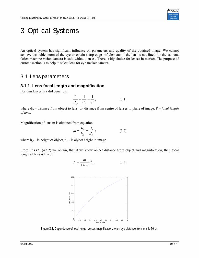
where hO – is height of object, hI – is object height in image. From Eqs (3.1)-(3.2) we obtain, that if we know object distance from object and magnification, then focal length of lens is fixed:
Odm
mF+
=1
. (3.3)
0 0.1 0.2 0.3 0.4 0.5 0.6 0.7 0.8 0.9 10
50
100
150
200
250
Magnification
Foca
l len
gth,
mm
Figure 3.1. Dependence of focal length versus magnification, when eye distance from lens is 50 cm

Communication by Gaze Interaction (COGAIN), IST-2003-511598
04.04.2007 20/47
The dependence of focal length versus magnification, when eye distance from lens is 50 cm, is shown in Figure 3.1. It is important to notice that, when magnification is 0.1, we need lens with focal length 45,5 mm. This indicates that for obtaining big zoom of the eye we need lens with big focal length. Wide angle lenses have small focal lengths. For eye tracking we need narrow angle lens.
3.1.2 F-number and image depth4 The aperture stop or stop of a lens is the limiting aperture associated with the lens that determines how large an axial beam may pass through the lens. The stop is also called an iris. The marginal ray is the extreme ray from the axial point of the object through the edge of the stop. The entrance pupil is the image of the stop formed by all lenses preceding it when viewed from object space. The exit pupil is the image of the stop formed by all lenses following it when viewed from image space. These pupils and the stop are all images of one another. The principal ray is defined as the ray emanating from an off-axis object point that passes through the centre of the stop. In the absence of pupil aberrations, the principal ray also passes through the centre of the entrance and exit pupils. As the obliquity angle of the principal ray increases, the defining apertures of the components comprising the lens may limit the passage of some of the rays in the entering beam thereby causing the stop not to be filled with rays. The failure of an off-axis beam to fill the aperture stop is called vignetting. The ray centred between the upper and lower rays defining the oblique beam is called the chief ray. When the object moves to large off-axis locations, the entrance pupil often has a highly distorted shape, may be tilted, and/or displaced longitudinally and transversely. Due to the vignetting and pupil aberrations, the chief and principal rays may become displaced from one another. In some cases, the principal ray is vignetted. The field stop is an aperture that limits the passage of principal rays beyond a certain field angle. The image of the field stop when viewed from object space is called the entrance window and is called the exit window when viewed from image space. The field stop effectively controls the field of view of the lens system. Should the field stop be coincident with an image formed within or by the lens system, the entrance and exit windows will be located at the object and/or image(s). A telecentric stop is an aperture located such that the entrance and/or exit pupils are located at infinity. This is accomplished by placing the aperture in the focal plane. Consider a stop placed at the front focal plane of a lens. The image is located at infinity and the principal ray exits the lens parallel to the optical axis. This feature is often used in metrology since the measurement error is reduced when compared to conventional lens systems because the centroid of the blur remains at the same height from the optical axis even as the focus is varied. The focal ratio or F-number (FN) of a lens is defined as the effective focal length divided by the entrance pupil diameter Dep. When the object is not located at infinity, the effective FN is given by
)1( mFNFNeff −= ∞ (3.4)
The numerical aperture of a lens is defined as
ii UnNA sin= (3.5)
where ni is the refractive index in which the image lies and Ui is the slope angle of the marginal ray exiting the lens. If the lens is aplanatic, then
NAFNeff 2
1= (3.6)
4 Section source: Johnson, 1994.
Communication by Gaze Interaction (COGAIN), IST-2003-511598
04.04.2007 21/47
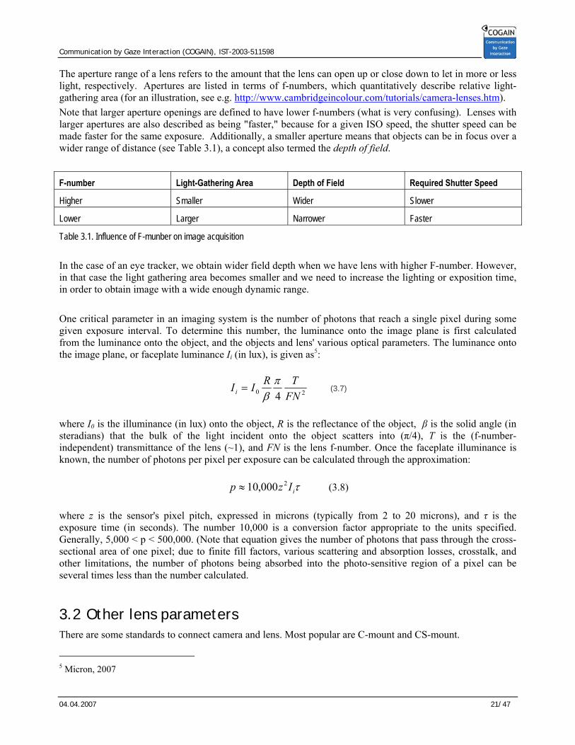
The aperture range of a lens refers to the amount that the lens can open up or close down to let in more or less light, respectively. Apertures are listed in terms of f-numbers, which quantitatively describe relative light-gathering area (for an illustration, see e.g. http://www.cambridgeincolour.com/tutorials/camera-lenses.htm). Note that larger aperture openings are defined to have lower f-numbers (what is very confusing). Lenses with larger apertures are also described as being "faster," because for a given ISO speed, the shutter speed can be made faster for the same exposure. Additionally, a smaller aperture means that objects can be in focus over a wider range of distance (see Table 3.1), a concept also termed the depth of field.
F-number Light-Gathering Area Depth of Field Required Shutter Speed
Higher Smaller Wider Slower
Lower Larger Narrower Faster
Table 3.1. Influence of F-munber on image acquisition In the case of an eye tracker, we obtain wider field depth when we have lens with higher F-number. However, in that case the light gathering area becomes smaller and we need to increase the lighting or exposition time, in order to obtain image with a wide enough dynamic range. One critical parameter in an imaging system is the number of photons that reach a single pixel during some given exposure interval. To determine this number, the luminance onto the image plane is first calculated from the luminance onto the object, and the objects and lens' various optical parameters. The luminance onto the image plane, or faceplate luminance Ii (in lux), is given as5:
20 4 FNTRIIi
πβ
= (3.7)
where I0 is the illuminance (in lux) onto the object, R is the reflectance of the object, β is the solid angle (in steradians) that the bulk of the light incident onto the object scatters into (π/4), T is the (f-number-independent) transmittance of the lens (~1), and FN is the lens f-number. Once the faceplate illuminance is known, the number of photons per pixel per exposure can be calculated through the approximation:
τiIzp 2000,10≈ (3.8)
where z is the sensor's pixel pitch, expressed in microns (typically from 2 to 20 microns), and τ is the exposure time (in seconds). The number 10,000 is a conversion factor appropriate to the units specified. Generally, 5,000 < p < 500,000. (Note that equation gives the number of photons that pass through the cross-sectional area of one pixel; due to finite fill factors, various scattering and absorption losses, crosstalk, and other limitations, the number of photons being absorbed into the photo-sensitive region of a pixel can be several times less than the number calculated.
3.2 Other lens parameters There are some standards to connect camera and lens. Most popular are C-mount and CS-mount.
5 Micron, 2007

Communication by Gaze Interaction (COGAIN), IST-2003-511598
04.04.2007 22/47
C-mount6 lenses provide a male thread which mates with a female thread on the camera. The thread is nominally 1 inch in diameter, with 32 threads per inch, designated as "1-32 UN 2A" in the ANSI B1.1 standard for unified screw threads. Distance from the lens mount flange to the focal plane is 17.526 mm (0.69 inches) for a C-mount. The same distance for CS-mount is 12.52 mm as other parameters are identical. C-mount lens can be mounted on CS camera using 5 mm extension ring. Most board lenses are threaded for M12 x 0.5mm. Many lenses have thread for filter. There are many different diameters for filter thread.
3.3 Calibration distortion models7 Interior Orientation Parameters (IOP) consist of the focal length, principal point coordinates, and image coordinate corrections that compensate for various deviations from the assumed perspective geometry. The perspective geometry is established by the collinearity condition, which states that the perspective center, the object point and the corresponding image point must be collinear (Kraus, 1993). A distortion in the image signifies that there is a deviation from collinearity. Potential sources of the deviation from collinearity are the radial lens distortion, de-centric lens distortion, atmospheric refraction, affine deformations and out-of-plane deformations (Fraser, 1997). All these sources of distortion are represented by explicit mathematical models whose coefficients are called the distortion parameters (e.g., K1, K2, K3… for radial lens distortion, P1, P2, P3
for de-centric lens distortion, and A1, A2 for affine deformations).
Radial lens distortion (RLD): The radial lens distortion occurs when the path of a light ray is altered as it passes through the perspective center of the lens. It is caused by large off-axial angles and lens manufacturing flaws, and takes place along a radial direction from the principal point. The correction for the radial distortion of the measured point is modeled by the polynomial series in the following equations (Kraus, 1997):
⎪⎩
⎪⎨⎧
+−+−+−=Δ
+−+−+−=Δ
...)1()1()1(
...)16()1()1(6
34
22
1
34
22
1
yrKyrKyrKy
xrKxrKxrKx
RLD
RLD
Where 22 )()( PP yyxxr −+−= ,
K1, K2
and K3
are the radial lens distortion parameters, xp
and yp
are the image coordinates of the principal
point, and x and y are the image coordinates of the measured point. The K1 term alone will usually suffice in
medium accuracy applications and for cameras with a narrow angular field of view. The inclusion of K2 and
K3 terms might be required for higher accuracy and wide-angle lenses. The decision as to whether incorporate
one, two, or three radial distortion terms can be based on statistical tests of significance. Another reason why estimating only K1
would be preferable is that estimating more than the required amount of distortion
parameters could increase the correlation between unknown parameters and this will likely affect the IOP estimates.
6 http://en.wikipedia.org/wiki/C_mount 7 Section reference: Pullivelli, 2005.

Communication by Gaze Interaction (COGAIN), IST-2003-511598
04.04.2007 23/47
De-centric lens distortion (DLD): The de-centric lens distortion is caused by inadequate centering of the lens elements of the camera along the optical axis. The misalignment of the lens components causes both radial and tangential distortions, which can be modeled by the following correction equations (Brown, 1966):
⎪⎩
⎪⎨⎧
++=Δ
++=Δ
xyPyrPy
xyPxrPx
DLD
DLD
122
2
222
1
2)2(
2)2(
Where: P1 and P
2 are the de-centric lens distortion parameters.

Communication by Gaze Interaction (COGAIN), IST-2003-511598
04.04.2007 24/47
4 Other Components for Gaze Trackers
4.1 Lighting Eye lighting is an important issue for eye tracking. Ambient light is hardly controlled. One of the factors that disturb the lighting of the eye is the computer monitor. When image brightness changes, it invokes eye illumination changes. The eye acts as a mirror and in the recorded image one could see the eye image with overlaid monitor’s image. It is better to avoid the ambient light variation using additional and stronger light source. As has already been considered, it is better to use infrared light sources. Small infrared light sources are infrared light emitting diodes (LEDs). Near infrared region LEDs are produced from solid solution GaAlAs or GaAs. GaAs LEDs gives 940 nm waves. More preferable are LEDs from GaALAs. Because it is solid solution, its composition can be controlled. It causes changes is semiconductor forbidden energy gap. So GaAlAs LED can be turned on different wavelengths as 850, 860, 870, or 880 nm. Some manufacturers of IR LEDS:
• Epitex, Japan, (http://www.epitex.com/global/index.htm); • Opto Diode Corporation, US, (http://www.optodiode.com); • Kingbright, Taiwan. (http;//www.kingbright.com). Kingbright Electronic Europe GmbH distributes
devices in EU countries; • Everlight Electronics Co, LTd., Taiwan (http://www.everlight.com).
IR LEDs can be purchased in many electronics components shops or online shops as:| • http://www.digikey.com; • http://www.conrad.de; • http://www.mouser.com.
4.2 Camera mounting systems The camera must be mounted so that mounting would easily allow to change the camera orientation. The simplest solution is to use tripos with pan & tilt head. A more advanced solution is a pan & tilt device, controlled from the PC. The best case is when the system controls not only camera orientation but also focusing and zoom of camera.
4.2.1 Eagle MotorPod The Eagletron (http://www.trackercam.com) MotorPod is a computer-controlled pan/tilt base for any camera under 2 lbs. It lets you turn and swivel your camera up, down, left, and right under the control of your PC. You can even control the optical zoom of compatible camcorders. MotorPod comes with the same sophisticated control software as the TrackerPod®, giving you features like Internet remote control, programmable video capture, and motion detection. It also works with Camcorders, Webcams Under 2 lbs. Maximum angles of rotation: 160 degrees pan and 110 degrees tilt. Maximum speed of movement: 53 degrees per second. MotorPod Interfaces to PC via USB port. Standard 1/4" #20 mounting thread screw on camcorder

Communication by Gaze Interaction (COGAIN), IST-2003-511598
04.04.2007 25/47
Optical zoom control available for Camcorders that use an IEEE 1394 (Firewire) interface and support the zoom command set (eg. Panasonic NV-GS70, Canon ZR in US, Canon MV in Europe, Canon Elura and Opturaseries). MotorPod comes free with TrackerCam® Software. Price for MotorPod is around 170USD on internet shop http://www.trackercam.com). Sony camcorder users: a special model of PowerPod, the PowerPod-LANC offers you optical zoom control Firewire or USB or video capture card interface between camcorder and PC.
4.2.2 Indoor Pan/Tilt unit Indoor Pan/Tilt unit includes the following features (http://www.rmassa.com/manu/hitachi.htm):
• Quiet operation using high torque stepper motors; • Serial RS-485 or RS-232 control; • Adjustable preset speeds with proportional speed control: • Adjustable end stops; • Supplies 12 VDC power for camera operation. Optional camera control module for full camera
control; • Price $2,024.
4.2.3 Directed Perception model PTU-D46 Manufacturer Directed Perception (http://www.dperception.com) offers some pan tilt systems models. Technical data of model MODEL PTU-D46-17:
• Simple control from host computer via RS-232/485; • Speeds to 300°/second; • Resolution to 0.012857° ; • Rated payload 6 lbs (2.72kg); • Price $2,100.
4.2.4 Edmund Optics articulated arm Edmund Optics (http://www.edmundoptics.com) offers different solution from pan & tilt system – articulated arm. It is designed for reaching into areas not easily accessible with standard 1/4-20 mounting, these “arms” can be positioned in any angular setting (180°) via the ball-pivot assembly. A total 360° rotation can be achieved by tilting/turning the knuckle about the shaft. Position can be locked into place with the easily handled knob or with the tamper-resistant set screw (Allen Key included). Applications range from mounting optical assemblies to fixturing CCD cameras. Individual components are available as well as One-arm and Two-arm packages. One-arm package includes two knuckles and one shaft. Extended One-arm package includes three knuckles and two shafts for added reach and range. Two-arm package includes four knuckles and two shafts for separate arm requirements, such as alignment of dual branch fibber optic light guides. Nylon washers provided with knuckles to avoid scratching anodized surfaces. Additional hardware pins (not included) are available.
4.3 Ultrasonic range finders For gaze control systems is important to be able to define the distance of the user’s eye from the computer screen. Ultrasonic range finders could help in such case. Robot Electronics (http://www.robot-

Communication by Gaze Interaction (COGAIN), IST-2003-511598
04.04.2007 26/47
electronics.co.uk/shop/Ultrasonic_Rangers1999.htm) offers ultrasonic range finder SRF02 with USB connectivity. Its parameters are:
• Range - 15cm - 6m; • Frequency - 40KHz; • Analogue Gain - Automatic 64 step gain control; • Light Weight - 4.6gm; • Size - 24mm x 20mm x 17mm height; • Voltage - 5v only required; • Connection to USB by USBI2C module (purchased separately). • Price for SRF02 - 15 EUR; USBPIC2 - 25 EUR.

Communication by Gaze Interaction (COGAIN), IST-2003-511598
04.04.2007 27/47
5 Eye Tracking Using ADI Blackfin Processors
Currently eye tracking algorithms are operating on desktop or laptop computers with powerful processors. It is also interest to implement algorithms on small computing devices that reduce the size of the eye tracking system. Small computing devices can be integrated with a video camera. Such a system is called smart camera. Using a smart camera the need for bulk data transfers from camera to desktop computer disappears. The output data from eye tracker take more time less data bytes than video data. A wireless data transfer interface, which allows bigger user mobility, can be used in a such case.
5.1 Architecture of ADI Blackfin processors The Micro Signal Architecture (MSA) core was jointly developed by Intel and Analog Devices Inc. (ADI) (http://www.analog.com/processors/blackfin/). From year 2000 ADI has put this core into it’s Blackfin processor family8. The family includes over 15 different devices/speed grade options, including a dual core chip where each core can run at 600MHz. The MSA core has the advantages of RISC-like microprocessor instruction set. It combines a dual-MAC (Multiply/Accumulate), and single-instruction, multiple-data (SIMD) multimedia capabilities into a single instruction-set architecture. Since the core was recently developed, it takes advantage of the experience that processor architects have gained over the past 25 years and attempts to meet the needs of DSP, microcontroller, and multimedia processing algorithms that are popular today. The DSP features include one instruction port and two separate data ports mapped to a unified 4GB memory space; two 16-bit, single-cycle throughput multipliers; two 40-bit split data ALUs; two 32-bit pointer ALUs with support for circular and bit-reversed addressing; two loop counters that allow nested, zero overhead looping; and hardware support for on-the-fly saturation and clipping. The microcontroller features include arbitrary bit manipulation; mixed 16-bit and 32-bit instruction encoding for high code density; memory protection; stack pointers and scratch SRAM for context switching; flexible power management; and an extensible, nested, and prioritized interrupt controller for real-time control. The multimedia features include four auxiliary 8-bit data ALUs and a rich set of alignment-independent, packed byte operation instructions. These instructions enable the acceleration of fundamental operations associated with video and imaging based applications. The Blackfin ADSP-BF533 device contains several on-chip peripherals. These include:
• Parallel Peripheral Interface (PPI); • Serial Ports (SPORTs); • Serial Peripheral Interface (SPI); • General-purpose timers; • Universal Asynchronous Receiver Transmitter (UART); • Real-Time Clock (RTC); • Watchdog timer; • General-purpose I/O (programmable flags).
8 http://docs.blackfin.uclinux.org/doku.php?id=blackfin_basics

Communication by Gaze Interaction (COGAIN), IST-2003-511598
04.04.2007 28/47
The Blackfin processor architecture structures memory as a single, unified 4Gbyte address space using 32-bit addresses. All resources, including internal memory, external memory, and I/O control registers, occupy separate sections of this common address space. Level 1 (L1) memories are located on the chip and are faster than the Level 2 (L2) off-chip memories. The processor has three blocks of on-chip memory that provide high bandwidth access to the core. This memory is accessed at full processor speed:
• L1 instruction memory - This consists of SRAM and a 4-way set-associative cache. • L1 data memory - This consists of SRAM and/or a 2-way set-associative cache. • L1 scratchpad RAM - This memory is only accessible as data SRAM and cannot be configured as
cache memory. External (off-chip) memory is accessed via the External Bus Interface Unit (EBIU). This 16-bit interface provides a glueless connection to a bank of synchronous DRAM (SDRAM) and as many as four banks of asynchronous memory devices including flash memory, EPROM, ROM, SRAM, and memory-mapped I/O devices. The PC133-compliant SDRAM controller can be programmed to interface to up to 128M bytes of SDRAM. The asynchronous memory controller can be programmed to control up to four banks of devices. Each bank occupies a 1M byte segment regardless of the size of the devices used, so that these banks are only contiguous if each is fully populated with 1M byte of memory. Blackfin processors do not define a separate I/O space. All resources are mapped through the flat 32-bit address space. Control registers for on-chip I/O devices are mapped into memory-mapped registers (MMRs) at addresses near the top of the 4G byte address space. These are separated into two smaller blocks: one contains the control MMRs for all core functions and the other contains the registers needed for setup and control of the on-chip peripherals outside of the core. The MMRs are accessible only in Supervisor mode. They appear as reserved space to on-chip peripherals. At Siauliai University for eye tracking were tested with two Blacfin processors: BF537 and BF 561. Their main parameters are presented in Table 5.1.
Specification Processor BF537 Processor BF561
Frequency 600 MHz 600 MHz
Number of operations per second (MAC)
1 200 000 2 400 000
Size of internal SRAM 132KB 328KB
Width of external memory bus 16 bits 32 bits
DMA controllers 1 of 16 bits 2 of32 bits
Table 5.1. Main parameters of processors BF537 and BF561 (Analog Devices, 2007)
5.2 uClinux uClinux is an operating system that is derived from the Linux kernel. It is intended for microcontrollers without Memory Management Units (MMU’s). It is available on many processor architectures, including the Blackfin processor. The official uClinux site is at http://www.uclinux.org/. Information on the ADI Blackfin

Communication by Gaze Interaction (COGAIN), IST-2003-511598
04.04.2007 29/47
processor can be found at blackfin.uclinux.org. Also it is known uClinux implementations for next microprocessors:
• Motorola DragonBall, ColdFire; • ARM7 TDMI; • Intel i960; • Microblaze; • NEC V850E; • Renesas H8.
Using uClinux it is possible to run different programs, which run on Linux OS. Only it is necessary to recompile source code by GNU Toolchain compiler and because of difference between Intel and Blackfin processors and to implement little changes. Tests with BF537-Ezkit development board revealed that uClinux is very stable system. The longest test time was one week.
5.3 Results As performance test was selected edge detection function cvCanny which is found in Open CV library (OpenCV, 2007). It was measured how many cycle the function needs to process 720x288 resolution image. The next results werw obtained:
• BF537-Ezkit card with BF537 0.1 revision processor , uClinux version 2.6.16.11-ADI-2006R1blackfin, compilator gcc version 3.4.5 ADi 2006R1 - 493-821 million cycles;
• BF561-Ezkit BF561 0.3 with BF561 0.3 two core processor, uClinux version 2.6.16.27-ADI-2006R2 - 46.6-66.2 million cycles.
Results revealed that two cores processor BF561 operates twice faster than Bf537 processor.
Function Duration in cycles, millions
Threshold 100 Threshold 1
getImage() 22.40 26.69
cvCanny() 45.84 65.49
sendto() 3.74 3.8
Kadro trukmė 72.00 95.99
Table 5.2. Function execution duration on processor BF561 Time for the execution of cvCanny function strongly depends on the threshold for edge detection. For a higher threshold, the execution time becomes smaller.

Communication by Gaze Interaction (COGAIN), IST-2003-511598
04.04.2007 30/47
6 Eye Tracker Layout Simulation and Experimental Results
6.1 Simulation framework
6.1.1 Introduction This section describes a collection of routines for simulating eye trackers – in particular, the gaze estimation step. To get started, start interpolate_test.m (which tests a simple interpolation-based algorithm) from a Matlab9 command line. The project uses a pseudo-object-oriented philosophy, i.e. Matlab structures are used to represent the various objects in the system (eyes, lights, cameras), and methods are implemented as functions that take the object they operate on as their first argument. The name of a method should start with the name of the type of object it operates on (e.g. eye look_at(), camera_project()); methods that create objects (“constructors”) have the suffix make (e.g. eye_make(), camera_make()).
6.1.2 Geometric conventions The following conventions are used in geometrical calculations:
• All points and vectors are represented in homogeneous coordinates; • All vectors are column vectors; • All coordinate systems are right-handed; • Note: For a camera whose image plane is the x-y-plane, this would mean that its optical axis points
along the negative z-axis; • All measurements are in metres; • Object transformation matrices always transform object coordinates to world coordinates.
Figure 6.1 Coordinate system
A transformation matrix is of the form, shown in Figure 6.2. Here d is just the position of the object in world coordinates; and to rotate an object around the centre of its local coordinate system by a matrix B, we just concatenate B onto A.
9 For more information about Matlab, see e.g. http://www.mathworks.com

Communication by Gaze Interaction (COGAIN), IST-2003-511598
04.04.2007 31/47
Figure 6.2 Form of transformation matrix
6.1.3 A Short example The following short example is designed to introduce some of the functions in the framework. The source files for the functions contain more detailed documentation. The example code can also be run using the file example.m. To begin with, we will run a test of a simple interpolation-based gaze estimation method: Interpolate_test(); The test requires a few moments to run; when it is finished, it shows a plot that visualizes the relative magnitude and direction of the error at different positions of the screen. Note that the size of the error arrows is not to the same scale as the screen coordinates. Eye, light, and camera objects As mentioned above, the framework follows an object-oriented philosophy. An eye object, for example, is created like this: e=eye_make(7.98e-3, [1 0 0; 0 0 1; 0 1 0]); The eye has a corneal radius of 7.98 mm and its optical axis points along the negative y-axis. (In the eye’s local coordinate system, the optical axis points along the negative z-axis. By specifying an eye-to-world transformation matrix that exchanges the y- and z-axis, we make the optical axis of the eye point along the negative y-axis of the world coordinate system.) We new position the centre of the eye at (x, y, z) = (0, 0.5, 0.2) (all coordinates in metres): e.trans(1:3, 4)=[0 500e-3 200e-3]’; Note that we use the subscript (1:3, 4) to access the position vector in the transformation matrix (denoted by d in the previous section). Next, we will create a light and set its position to (0.2, 0, 0): l=light_make(); l.pos=[200e-3 0 0 1]’; Because lights are modelled as perfect point light sources, they do not have an orientation, and hence they do not need a full transformation matrix; only the position has to be specified. We also create a camera: c=camera_make(); In its local coordinate system, the camera points out along the negative z-axis. We want to change the camera’s orientation so that it points along the positive y-axis, towards the eye: c.trans(1:3,1:3)=[1 0 0; 0 0 -1; 0 1 0];
Communication by Gaze Interaction (COGAIN), IST-2003-511598
04.04.2007 32/47
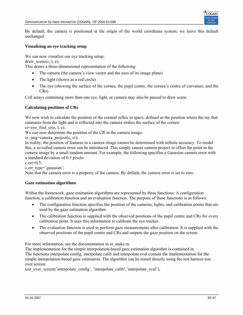
By default, the camera is positioned at the origin of the world coordinate system; we leave this default unchanged. Visualizing an eye tracking setup We can now visualize our eye tracking setup: draw_scene(c, l, e); This draws a three-dimensional representation of the following:
• The camera (the camera’s view vector and the axes of its image plane) • The light (shown as a red circle) • The eye (showing the surface of the cornea, the pupil centre, the cornea’s centre of curvature, and the
CRs) Cell arrays containing more than one eye, light, or camera may also be passed to draw scene. Calculating positions of CRs We now wish to calculate the position of the corneal reflex in space, defined as the position where the ray that emanates from the light and is reflected into the camera strikes the surface of the cornea: cr=eye_find_cr(e, l, c); We can now determine the position of the CR in the camera image: cr_img=camera_project(c, cr); In reality, the position of features in a camera image cannot be determined with infinite accuracy. To model this, a so-called camera error can be introduced. This simply causes camera project to offset the point in the camera image by a small random amount. For example, the following specifies a Gaussian camera error with a standard deviation of 0.5 pixels: c.err=0.5; c.err_type=’gaussian’; Note that the camera error is a property of the camera. By default, the camera error is set to zero. Gaze estimation algorithms Within the framework, gaze estimation algorithms are represented by three functions: A configuration function, a calibration function and an evaluation function. The purpose of these functions is as follows:
• The configuration function specifies the position of the cameras, lights, and calibration points that are used by the gaze estimation algorithm.
• The calibration function is supplied with the observed positions of the pupil centre and CRs for every calibration point. It uses this information to calibrate the eye tracker.
• The evaluation function is used to perform gaze measurements after calibration. It is supplied with the observed positions of the pupil centre and CRs and outputs the gaze position on the screen.
For more information, see the documentation in et_make.m. The implementation for the simple interpolation-based gaze estimation algorithm is contained in The functions interpolate config, interpolate calib and interpolate eval contain the implementation for the simple interpolation-based gaze estimation. The algorithm can be tested directly using the test harness test over screen: test_over_screen(’interpolate_config’, ’interpolate_calib’,’interpolate_eval’);

Communication by Gaze Interaction (COGAIN), IST-2003-511598
04.04.2007 33/47
6.1.4 Functions This function summarizes the most important functions in the framework. Detailed documentation for the functions can be found in the Matlab source files. Eye functions: eye_make Creates a structure that represents an eye. eye_draw Draws a graphical representation of an eye. eye _ind_cr Finds the position of a corneal reflex. eye_find_refraction Computes observed position of intraocular objects. eye_get_pupil_image Computes image of pupil boundary. eye_get_pupil Returns an array of points describing the pupil boundary. eye_look_at Rotates an eye to look at a given position in space. eye_refract_ray Computes refraction of ray at cornea surface. Light functions: light_make Creates a structure that represents a light. light_draw Draws a graphical representation of a light. Camera functions: camera_make Creates a structure that represents a camera. camera_draw Draws a graphical representation of a camera. camera_pan_tilt Pans and tilts a camera towards a certain location. camera_project Projects points in space onto the camera’s image plane. camera_take_image Computes the image of an eye seen by a camera. camera_unproject Unprojects a point on the image plane back into 3D space. Optical helper functions: reflect_ray_sphere Reflects ray on sphere refract _ray_sphere Refracts ray at surface of sphere find_reflection Finds position of a glint on the surface of a sphere find_refraction Computes image produced by refracting sphere Test harnesses test_over_observer Computes gaze error at different observer positions test_over_screen Computes gaze error at different gaze positions on screen Preimplemented gaze estimation algorithms beymer_* Method of Beymer and Flicker (2003). interpolate_* Simple interpolation-based method. shihwuliu_* Method of Shih, Wu, and Liu (2000). yoo_* Method of Yoo and Chung (2005).

Communication by Gaze Interaction (COGAIN), IST-2003-511598
04.04.2007 34/47
7 Developed Systems
In this section, the systems build by COGAIN partners are briefly described from the hardware point of view (see COGAIN deliverable D5.2 by Daynys et al. 2006 for more information about the systems). The performance of eye tracking systems significantly depends on used algorithms. The full analysis of systems performance is out the scope of current deliverable.
7.1 UzL
Figure 7.1. View of system build in UzL Components of UzL (Universität zu Lübeck) system:
• Camera Lumenera Lu 125 M (interface USB 2.0, resolution 1280x1024, frame/rate: 15 Hz, price around 800 EUR, link: www.lumenera.com);
• Optics - Pentax 16mm C-mount lens C1614-M (fixed focus, price around 100EUR, links: http://www.pentax.de/_de/cctv/products/index.php?cctv&products&ebene1=1&ebene2=8&produkt=C31634KP, http://www.phoeniximaging.com/c1614-m.htm);
• Illuminators Epitex L870 (lighting range 870 nm, viewing half angle +/- 15 degrees). • Fillter Heliopan RG 830 (infrared filter, price arround 50EUR, link:
http://www.heliopan.de/produkte/infrarotfilter.shtml). The camera allows a ROI to be defined, and frame rate increases linearly as the size of the ROI is reduced. However, a major disadvantage is that the position of the ROI cannot be changed while the camera is streaming frames; instead, the camera has to be stopped, the ROI can then be changed, and then the camera must be restarted. For this reason, it is not practicable to track the user's head with a moving ROI. Price for hardware components (without computer) is around 1000 EUR.

Communication by Gaze Interaction (COGAIN), IST-2003-511598
04.04.2007 35/47
7.2 UNI KO-LD
Figure 7.2. View of UNI KO-LD system
Camera and IR lights are on a rigg to test different distances between camera and eyes. To test different illumination intensities, there are 9 infrared LEDs, but are used only up to 3 most of the time. At partner UNI KO-LD (Universität Koblenz-Landau), different cameras were tested for the corneal reflection approach.
• a FireWire camera from UniBrain, Inc, named Fire-I, offering 640x480 pixel in color at up to 30 fps at a price of 109,- EUR;
• a low cost USB 2 based PC-Camera (“web cam”) named SN9C201 from an unknown manufacturer, providing 640x480 at 25 fps for approx. 15,- EUR;
• a small high sensitivity camera with a conventional, analogue video output named 2005XA from RF-Concepts, Ltd. At 90,- EUR.

Communication by Gaze Interaction (COGAIN), IST-2003-511598
04.04.2007 36/47
7.3 SU
Figure 7.3. SU eye tracking system
Components of SU (Siauliu Universitetas) system: • Camera - Basler 602f (monochrome CMOS sensor, resolution 656x491, ROI, frame rate until 300 fps
with small ROI, price around 1200 EUR); • Lens - Pentax zoom C6ZE (C-mount, for sensor 2/3”, focal length 12.5-75 mm, manual zoom and
focus, minimal focusing distance 1 m, filter screw size 49 mm, price around 615 EUR); • Close up lens – Pentax CP2/49 ( 2D, for focusing in close distance, less than 1 m) • Illumination - IR LED 880 nm 5 mm (of unknown manufacturer) • Filter - infrared filter Hoya R-72 (passes only infrared rays above 720 nm).
7.4 UPNA
Figure 7.4 UPNA1 system

Communication by Gaze Interaction (COGAIN), IST-2003-511598
04.04.2007 37/47
Components of the UPNA1 (Universidad Publica de Navarra) system : • Camera- Hamamatsu c5999 (monochrome CCD camera, sensor 2/3”, resolution 640x480, frame rate
until 30 fps with price around 3000 EUR). Is not longer manufactured. High sensitivity in the infrared.
• Lens-Navitar zoom lens - (C-mount, for sensor 2/3”, focal length 75-135 mm, manual zoom and focus, price around 800 EUR);
• Illumination – Hamamatsu IR LED 880 nm L7558-01. • Filter –band pass filter (880nm) Ealing.
Figure 7.5 UPNA system
Components of UPNA2 system *: • Camera- standard CCD camera (monochrome, resolution 1024x768, frame rate until 30 fps with price
around 800-900 EUR); • Lens - (C-mount, for sensor 2/3”, focal length 25/35 mm, manual zoom and focus, filter screw size
25 mm, price around 180 EUR); • Illumination - IR LED 890 nm (of unknown manufacturer) • Filter - infrared.
* detailed information about some hardware elements is restricted by the system manufacturer.

Communication by Gaze Interaction (COGAIN), IST-2003-511598
04.04.2007 38/47
7.5 UNIZH
Figure 7.6 Silicon retina system from UNIZH
Components of UNIZH (Universität Zürich, also referred as UNI-ETH) system
• Camera: UNIZH own custom-designed event-based temporal contrast silicon retina. USB 2 interface. • Resolution: 128x128 (spatial). Frame/rate: >10k. Sensitivity: 120dB. Price: >1000 euro, limited
availablity • Link: http://siliconretina.ini.uzh.ch. UNIZH is developing new event-driven tracking algorithms
around this sensor. • Illuminators: IR LED. Lighting range: 10cm. A single LED is near the lens, in line with the optical
axis, to illuminate the eye. • Lens: Standard 8mm mini lens, mounted on glasses near eye • Infrared filters are not used.

Communication by Gaze Interaction (COGAIN), IST-2003-511598
04.04.2007 39/47
7.6 CTU
Figure 7.7. The I4Control ® system
Components of the CTU (Czech Technical University) I4Control system
• Camera: ordinary small camera with composite video output. Resolution: 320x240 pixels, frame/rate: 25 images/second or less – the rate can be chosen w.r.t. performance of the used computer.
• A common grab card for PC. • The optics: provided by the camera manufacturer - no special modifications are applied. • Illuminators: IR diodes. • Infrared filters are not used.
The camera is attached to the frame of spectacles. On the same frame close to the camera are located IR diodes. USB interface is used to switch on/off the camera and to change the infra-red illumination strength. The system automatically modifies the strength of IR signal to minimize the value of the ratio between the strength of the IR signal (which should be as low as possible) and results of the algorithm for detection of pupil position (these should be as good as possible). Video signal is processed by the common grab card in PC. The pilot series of several pieces will be produced in May 2007 – each is expected to cost less than 700 EUR. It is expected that the final product will be significantly cheaper.

Communication by Gaze Interaction (COGAIN), IST-2003-511598
04.04.2007 40/47
8 References
Analog Devices (2007). Analog Devices: Embedded Processing and DSP: Blackfin Processors Home. http://www.analog.com/processors/blackfin/
Axelson, J. (2005) USB Complete. http://www.lvr.com/files/usb_complete_chapter1.pdf Basler (2007). Basler 601f, 602f and 622f Data Sheet. Available online at
http://www.baslerweb.com/downloads/15581/A600Boardlevel.pdf Beymer, D. and Flickner, M. (2003). Eye gaze tracking using an active stereo head. In Proceedings of
Computer Vision and Pattern Recognition (CVPR), volume 2, pp. 451–458. Blackfin uclinux (2007). Linux on the Blackfin Processors. http://blackfin.uclinux.org Brolly, X. L. C. and Mulligan, J. B. (2004). Implicit calibration of a remote gaze tracker. In Proceedings of
the 2004 Conference on Computer Vision and Pattern Recognition Workshop (CVPRW ’04), volume 8, pp. 134.
Brown, D.C., (1966). Decentering distortion of lenses. Photogrammetric Engineering, 32(3): 444–462. Dalsa (2007) Dalsa Disital Imaging Technical Papers. http://vfm.dalsa.com/support/techpapers/techpapers.asp Daunys, G. et al. (2006) D5.2 Report on New Approaches to Eye Tracking. Communication by Gaze
Interaction (COGAIN), IST-2003-511598: Deliverable 5.2. Available at http://www.cogain.org/results/reports/COGAIN-D5.2.pdf
EdmundOptics (2007). Edmund Optics, Ltd. homepage. http://www.edmundoptics.com Guestrin, E. D. and Eizenman M. (2006) General theory of remote gaze estimation using the pupil center and
corneal reflections. IEEE Transactions on Biomedical Engineering, vol. 53(6), pp. 1124–1133. Johnson R. B. (1994). Chapter 1. Lenses. In Handbook of Optics, Second Edition. McGraw-Hill , Inc. Hennessey, C., Noureddin, B., and Lawrence, P. (2006). A single camera eye-gaze tracking system with free
head motion. In Proceedings of Eye Tracking Research & Applications (ETRA), pp. 87–94. Kraus, K. (1993). Advanced Methods and Applications. Vol.2. Fundamentals and Estándar Processes. Vol.1.
Institute for Photogrammetry Vienna University of Technology. Ferd. Dummler Verlag. Bonn. Kraus K., (1997). Choice of Additional Parameters, Photogrammetry Volume 2 – Advanced Methods and
Applications, Fred. Dümmlers Verlag, Bonn, pp. 133–136. Lumenera (2007). http://www.lumenera.com Meyer, A., Bohme, M., Martinetz, T., and Barth E. (2006). A single-camera remote eye tracker. In Perception
and Interactive Technologies, volume 4021 of Lecture Notes in Artificial Intelligence, pages 208–211. Springer, 2006.
Micron (2007). Micron Imaging Technology. http://www.micron.com/innovations/imaging/ NASA (2007). NASA Technical Reports server. http://ntrs.nasa.gov Ohno, T. and Mukawa, N. (2004). A free-head, simple calibration, gaze tracking system that enables gaze-
based interaction. In Eye Tracking Research and Applications (ETRA), pp. 115–122, 2004. OpenCV (2007). Sourceforge.net: Open Computer Vision Library.
http://sourceforge.net/projects/opencvlibrary Prosilica (2007) Why Firewire? http://www.prosilica.com/support/why_firewire.htm Pullivelli, A. (2005) Low-Cost Digital Cameras: Calibration, Stability Analysis, and Applications. Thesis.
Department of Geomatics Engineering, University of Calgary. Available online at http://www.geomatics.ucalgary.ca/Papers/Thesis/AH/05.20216.AnoopPullivelli.pdf
RF-Concepts (2007). CCTV cameras. http://www.rfconcepts.co.uk

Communication by Gaze Interaction (COGAIN), IST-2003-511598
04.04.2007 41/47
Shih, S.-W., Wu, Y.-T.and Liu J. (2000). A calibration-free gaze tracking technique. In Proceedings of the 15th Inter-national Conference on Pattern Recognition, pp. 201–204.
Smith W. J. (2000). Modern Optical Engineering. Third Edition. McGraw-Hill , Inc. Sony Global (2007). B/W video camera CCD.
http://www.sony.net/Products/SC-HP/pro/image_senser/bw_video.html Tobii (2002). Tobii 1750 eye tracker, Tobii Technology AB, Stockholm, Sweden, http://www.tobii.se. Eagletron (2007). USB pan/tilt tripods by Eagletron. http://www.trackercam.com uClinux (2007). uClinux™ - Embedded Linux Microcontroller project. http://www.uclinux.org Unibrain (2007). UniBrain homepage. http://www.unibrain.com Yoo, D. H., Chung, M. J. (2005). A novel non-intrusive eye gaze estimation using cross-ratio under large
head motion. Computer Vision and Image Understanding, vol 98, 1, pp. 25–51.

Communication by Gaze Interaction (COGAIN), IST-2003-511598
04.04.2007 42/47
Appendix A: Manufacturers of cameras with FireWire (IEEE-1394) interface
Manufacturer Internet address Type of sensors
Aglaia www.aglaia-gmbh.de Color, mono, CMOS
Allied Vision Technologies www.aliedvisiontech.com Color, mono, CMOS, CCD
AME Optimedia www.vcam.com.tw Color CCD
AOS www.aostechnologies.com Mono CMOS
Apple www.apple.com Color CCD
Basler www.baslerweb.com Mono, color, CMOS, CCD
Baumer Optronic www.baumeroptronic.de Mono, color, CMOS, CCD
Canon www.canon.com Color, CCD, CMOS
C-Cam Technologies www.vector-international.be/C-Cam/Cindex.html Color, mono, CMOS
CCD Direct www.ccddirect.com Mono, color, CCD
Cohu www.cohu-cameras.com Mono, color, CCD
Cool Stream www.cool-stream.net Color, CCD
Dage-MTI www.dagemti.com IR, color, mono, CCD
Desert Star www.desertstar.com Mono, color, CCD, CMOS
Diagnostic Instruments www.diaginc.com Mono, color, CCD
DVC Company www.dvcco.com IR, mono, color, CCD
First Vision www.1stvision.com Mono. Color, CCD
Fuji www.fujifilm.com Color, CCD
Hamamatsu usa.hamamatsu.com Mono, CCD
Hasselblad www.hasselblad.se Color, CCD
Hitachi www.hitachižke-eu.com Mono, color, CCD
The Imaging Source www.1394imaging.com Mono, color, CCD
IMI Tech. www.imi-tech.com Color, CCD
Integrated Design Tools www.idtpiv.com Mono, CCD
iRez www.irez.com Color, CCD
ISG www.isgchips Mono, color, CMOS

Communication by Gaze Interaction (COGAIN), IST-2003-511598
04.04.2007 43/47
Jenoptik www.progres-camera.com Mono, color, CCD, CMOS
JVC pro.jvc.com Color, CCD, 3CCD
Kamera Werk Dresden www.kamera-werk-dresden.de Mono, color, CMOS
Kappa www.kappa.de Mono, color, CCD
Kodak www.kodak.com Color, CMOS
Leaf www.leafamerica.com Color
Leica Photo www.leica-camera.com Color, CCD
Leica Microsystems www.leica-microsystems.com Mono, color, CCD
Megavision www.mega-vision.com Color, CCD
NET GmBH www.net-gmbh.com Mono, color, CCD
Olympus www.olympus.com Color, CCD
Optronics www.optronics.com Mono, color, CCD
Optronis www.optronis.com Color, CMOS
PCO www.pco.de Mono, CMOS
Perkin Elmer www.perkinelmer.de Mono
Phase One www.phaseone.com Color
Philips www.apptech.philips.com/industrialvision Mono, CMOS
Photonic Science www.photonic-science.co.uk Mono
Photron www.photron.com Mono, color, CMOS
Phytec www.phytec.de Mono, color, CCD
Point Grey www.ptgrey.com Mono, color, CMOS, CCD
Princeton Instruments www.piacton.com Mono, CCD
Prosilica www.prosilica.com Mono, color, CMOS, CCD
Q-Imaging www.qimaging.com Mono, color, CCD, CMOS
Redlake www.redlake.com Mono, color, CCD
Scion www.scioncorp.com Mono, color, CCD
Sigma www.sigmaphoto.com Color, CMOS
Sensovation www.sensovation.com Mono, color, CCD, CMOS
Sinar www.sinarbron.com Color, CCD
Soft Imaging www.soft-imaging.com Color, CCD
Soliton www.solitontech.com Mono, CMOS
Sony www.sony-vision.com Mono, color, CCD, 3CCD

Communication by Gaze Interaction (COGAIN), IST-2003-511598
04.04.2007 44/47
Suekage www.suekage.com/index.html Color
Toshiba Teli www.toshiba-teli.co.jp/english Mono, color, CCD, CMOS
Theta Systems www.theta-system.de Mono, color, CMOS, CCD
Thorlabs www.thorlabs.com Mono, color, CCD
TI www.ti.com Color, CCD
Unibrain www.unibrain.com Mono, color, CCD
VDS-Vosskuhler www.vdsvossk.de/en Mono, color, CCD
Videre Design www.videredesign.com Mono, color, CMOS, CCD
Visible Solutions www.visiblesolutions.com Mono, color, CMOS
Vitana www.pixelink.com Mono, color, CMOS
VX Technologies www.vxtechnologies.com Mono, color, CCD
Zeiss www.zeiss.com Color, CCD

Communication by Gaze Interaction (COGAIN), IST-2003-511598
04.04.2007 45/47
Appendix B: Main manufacturers of lenses
Manufacturer Internet address
COMPUTAR http://www.computar.jp/
http://www.cbceurope.com/
Edmund Optics www.edmundoptics.com
Fujinon www.fujinon.co.jp/en
Leica Technologies, Inc. www.leica.com
Navitar Inc. www.navitar.com/
Pentax www.pentax.com
www.pentax.co.uk
Schneider Optics Inc www.schneideroptics.de/index_e.htm
www.schneideroptics.com
Tamron www.tamron.com

Communication by Gaze Interaction (COGAIN), IST-2003-511598
04.04.2007 46/47
Appendix C: Internet shops for hardware components
Internet address Remarks
www.1stvision.com Cameras
www.adorama.com IR filters, tripods, pan & tilt heads
www.bhphotovideo.com Pan & tilt heads, tripods, webcams
www.ccddirect.com Cameras
www.edmundoptics.com Machine vision cameras, lenses, articulated arm
www.imaginghardware.com Cameras, lenses
www.rfconcepts.co.uk Cameras, lenses
www.rmassa.com Cameras, lenses, framegrabbers

Communication by Gaze Interaction (COGAIN), IST-2003-511598
04.04.2007 47/47
Appendix D: Useful links
Internet address Remarks
http://www.cambridgeincolour.com/tutorials/camera-lenses.htm About camera lenses
http://vfm.dalsa.com/support/techpapers/techpapers.asp About Image sensors
http://www.micron.com/products/cmos/ CMOS image sensors