Embed Size (px)
Citation preview
D5.1 Evaluation of existing methods and principles
Heidi Dahl, Mass Soldal Lund, Ketil Stølen (SIN), Valentino Meduri, Massimo Felici, Alessandra Tedeschi (DBL), Veronique Normand, Benjamin Fontan (THA), Frank Innerhofer-Oberperfler (UIB), Fabio Massacci, Elisa Chiarani (UNITN)
Document information
Document Number D5.1
Document Title Evaluation of existing methods and principles
Version 3.0
Status Final
Work Package WP 5
Deliverable Type Report
Contractual Date of Delivery 31 July 2009
Actual Date of Delivery 31 July 2009
Responsible Unit SIN
Contributors SIN, UNITN, DBL, THA, UIB
Keyword List Evaluation, language, methods, principles, risk analysis, evolving systems
Dissemination level PU
Evaluation of existing methods and principles |
version 3.0 | page 2 / 59
Document change record
Version Date Status Author (Unit) Description
0.1 11 March 2009 Draft Heidi Dahl (SIN) Outline
1.0 27 March 2009 Draft Heidi Dahl, Mass
Soldal Lund, Ketil
Stølen (SIN)
First draft of SotA
chapters
1.1 21 June 2009 Working Heidi Dahl, Mass
Soldal Lund, Ketil
Stølen (SIN),
Valentino Meduri,
Massimo Felici,
Alessandra
Tedeschi (DBL),
Frank Innerhofer-
Oberperfler (UIB),
Fabio Massacci
(UNITN)
Problem characterization,
more SotA included
1.2 24 June 2009 Working Heidi Dahl, Mass
Soldal Lund, Ketil
Stølen (SIN),
Veronique
Normand,
Benjamin Fontan
(THA)
Introduction, more SotA
included, first draft of
evaluation and
conclusion
1.3 3 July 2009 Working Heidi Dahl (SIN) More SotA included,
evaluation and
conclusions, appendix
with glossary
2.0 31 July 2009 Draft Heidi Dahl (SIN) Final version completed
with input from internal
reviewers
3.0 31 July 2009 Final Elisa Chiarani
(UNITN)
Final version for
deliverable
Evaluation of existing methods and principles |
version 3.0 | page 3 / 59
Executive summary
Work Package 5 of the SecureChange project will develop four main artefacts: a language, a method, a documentation framework and a tool supporting risk analysis of evolving systems. Change and evolution in risk analysis can be categorised into tree perspectives and four kinds.
The perspectives on change are:
1. The maintenance/a posteriori perspective.
2. The before-after/a priori perspective.
3. The continuous perspective.
The kinds of changes relevant for risk analysis are:
1. Changes to target.
2. Changes to environment assumptions.
3. Changes to scope.
4. Changes to knowledge.
Success criteria for each of the four artefacts are defined with respect to each of the perspectives, and used to evaluate existing methods and principles relevant to the work package. This evaluation shows that the state-of-the-art provides partial support for the criteria defined for the maintenance/a posteriori perspective, little, but some, support for the before-after/a priori perspective, and almost no support for the continuous perspective. On the other hand, the continuous perspective is the most general and interesting, and it is support for the continuous perspective that should be our goal in the work package.

Evaluation of existing methods and principles |
version 3.0 | page 4 / 59
Index
DOCUMENT INFORMATION 1
DOCUMENT CHANGE RECORD 2
EXECUTIVE SUMMARY 3
1 INTRODUCTION 6
2 PROBLEM CHARACTERIZATION 7
2.1 Perspectives on Change 7
2.2 Kinds of Change 8 2.2.1 Changes to the Target 8 2.2.2 Changes to Environment Assumptions 9 2.2.3 Changes to the Scope of the Analysis 10 2.2.4 Changes in our Knowledge 10 2.2.5 Process of Change 10
2.3 Change in the SecureChange Case Studies 10 2.3.1 Air Traffic Management (ATM) Case Study 11
2.4 Evaluation Criteria 13 2.4.1 Language 14 2.4.2 Method 15 2.4.3 Documentation Framework 15 2.4.4 Tool 16
3 STATE-OF-THE-ART 17
3.1 Risk Management 17 3.1.1 Microsoft’s Security Risk Management 18 3.1.2 NIST SP800-30 18 3.1.3 The ProSecO Approach to Risk Management 18 3.1.4 The Integrated Risk Picture for ATM in Europe 20
3.2 Risk Modelling 21 3.2.1 Fault Trees 21 3.2.2 Event Trees 22 3.2.3 Cause-Consequence Diagrams 22 3.2.4 Attack Trees 23 3.2.5 OCTAVE Threat Tree 24 3.2.6 Bayesian Networks 25 3.2.7 Markov Diagrams 25 3.2.8 CORAS Risk Modelling Language 26 3.2.9 Domain-Specific Modelling Language for Security Analysis 27 3.2.10 Misuse Cases 28
Evaluation of existing methods and principles |
version 3.0 | page 5 / 59
3.2.11 UMLsec 29 3.2.12 SecureUML 29 3.2.13 Microsoft’s Threat Modelling (DREAD) 30 3.2.14 The ProSecO Approach to Risk Modelling 30 3.2.15 Tropos Goal-Risk Modelling 32 3.2.16 ADONIS 33
3.3 Risk Analysis 34 3.3.1 Hazard and Operability Analysis (HazOp) 35 3.3.2 Failure Mode Effect Analysis/Failure Mode Effect and Criticality Analysis (FMEA/FMECA) 35 3.3.3 Operationally Critical Threat, Asset and Vulnerability Evaluation (OCTAVE) 36 3.3.4 CCTA Risk Analysis and Management Method (CRAMM) 36 3.3.5 Facilitated Risk Assessment Process (FRAP) 37 3.3.6 Strengths, Weaknesses, Opportunities and Threats (SWOT) Analysis 37 3.3.7 The CORAS Method for Risk Analysis 38 3.3.8 Security DSML Risk Analysis Approach 39 3.3.9 Risk Analysis for the Integrated Risk Picture for ATM in Europe 40 3.3.10 The ProSecO Approach to Risk Analysis 40 3.3.11 Tropos Risk Assessment and Treatment 41
3.4 Change Management in Relation to Risk Management an d Analysis 42 3.4.1 The ProSecO Approach 43 3.4.2 Maintenance of Risk Analyses in CORAS 44 3.4.3 Other Approaches 46
4 EVALUATION 47
4.1 Language 47
4.2 Method 48
4.3 Documentation Framework 48
4.4 Tool 49
5 CONCLUSIONS 50
5.1 Language 50
5.2 Method 50
5.3 Documentation Framework 51
5.4 Tool 51
APPENDIX: GLOSSARY 52
REFERENCES 54

Evaluation of existing methods and principles |
version 3.0 | page 6 / 59
1 Introduction
The purpose of this deliverable is to evaluate existing methods and principles for risk assessment and risk analysis of security, privacy and dependability. In this evaluation we identify strengths and weaknesses of existing methods and techniques with respect of assessing and analysing risk of long-lived, changing and evolving systems.
The purpose of this state of the art is twofold: Firstly, it defines the point of departure for Work Package 5, the basis on which we will be building the results of the work package. The other function of the report is to gain an overview of the competences of the partners involved in the work package, so that our resources are used as efficiently as possible.
The evaluation is based on a number of initial success criteria defined for the work package. These are based on an analysis and classification of changes and evolution we expect long-lived systems to exhibit, as well as requirements to methodological support from the industrial case studies. The success criteria may be seen as part of the specification of the innovations expected to come out of Work Package 5 of the SecureChange project. Obviously, we do not expect the criteria to be fulfilled within the state-of-the-art; the purpose of the evaluation is to identify the starting point, as well as useful approaches and ideas.
The reminder of this deliverable is structured as follows:
– In Section 2 we present a first classification of kinds of change, provide a brief presentation of the industrial case studies, and define initial success criteria for the innovations of Work Package 5.
– In Section 3 we present the state-of-the-art itself; i.e. existing approaches to management, modelling, assessment and analysis of risk and of change.
– In Section 4 we evaluate the state-of-the-art from Section 3 with respect to the criteria presented in Section 2.
– In Section 5 we provide conclusions and directions for Work Package 5.
– In the appendix we provide a glossary of central risk analysis concepts.
Evaluation of existing methods and principles |
version 3.0 | page 7 / 59
2 Problem Characterization
A risk analysis typically focuses on a particular configuration of the target at a particular point in time, and is valid under the assumptions made in the analysis. However, both the risk analysis target and its environment change over time. We therefore need methods and techniques for having these changes reflected in the risk analysis.
How we handle changes in a risk analysis depends to a large degree on the context and the types of changes we are dealing with: Are the changes the results of maintenance or of bigger, planned changes? Are the changes a transition from one stable state of the target to another or the continuous evolution of a target designed to change over time? Do the changes occur in the target or in the environment of the target? The answers to such questions decide how we handle the changes. We therefore start by looking at different perspectives on change in Section 2.1 and different types of changes in Section 2.2. In Section 2.3 we look specifically at changes in the SecureChange case studies, and in Section 2.4 we define evaluation criteria based on the discussions of this problem characterisation.
2.1 Perspectives on Change As stated above, the context of the changes is of importance for what kind of approach we choose for dealing with the changes in risk analysis. There are two dimensions to what we define as the change perspective. The first is whether the change was planned or not, i.e. if the risk analysis is pro- or re-active. The second dimension is captured by the concepts of evolution and revolution:
– Evolution: Smaller changes that accumulate over time. Bug fixes and upgrades of computer systems are typically an evolution.
– Revolution: Major changes that have large effects on the target. The rollout of a new system is a typical example of a revolution.
Using these two dimensions, we identify three different viewpoints or perspectives on change:
1. The maintenance perspective (a posteriori perspective): Sometimes the target evolves over time, changes accumulate unnoticed, and risk analysis documentation and results may become outdated. An outdated risk analysis may give a false picture of the risks associated with the target and when changes occur we may need to conduct a new risk analysis. Conducting a risk analysis from scratch is expensive and time-consuming, and we would rather like to update the documentation from the risk analysis that we have already conducted. In terms of the dimensions defined above, the maintenance perspective is a reactive evolution.
2. The before-after perspective (a priori perspective): We often plan and anticipate changes, and major changes to the target may even be the motivation for a risk analysis. Such planned changes require special treatment for two reasons: First, it is very important to have a clear understanding of what characterises

Evaluation of existing methods and principles |
version 3.0 | page 8 / 59
the target “as-is” and what characterises the target “to-be”, and of what are the differences between these two. Second, the process of change may itself be a source of risks. In terms of the perspective dimensions, before-after is proactive revolution.
3. The continuous perspective: There may be cases where we plan for the target to evolve over time or where we can anticipate gradual changes, e.g. if we plan to gradually increase the number of components working in parallel, if we plan to gradually include more and more sites into a system, or if we foresee an increase in users of a system or the number of attacks by an adversary. What is common to such cases is that the target can be described as function of time. Obviously then, it would be a benefit if we could also do a risk analysis that is a function of time. Such a risk analysis would give a risk picture not for one or a few, but for any future point in time. In terms of the perspective dimensions, the continuous perspective is proactive evolution.
When it comes to the last combination of the perspective dimensions, reactive revolution, this would be a large unforeseen change that necessitates a new risk analysis. As for the maintenance perspective, in this situation we would prefer to be able to update the documentation from previous analyses rather than start from scratch. In the following we will limit the success criteria to the first three perspectives, as the fourth will have the same success criteria as the first.
2.2 Kinds of Change During the preliminary stages of a risk analysis, information is collected and organised to describe the target of analysis and its environment. The scope for the analysis is also set, defining the parts of the system relevant to the analysis. Change in any of these three descriptions may cause changes in the outcome of the risk analysis. Such a change may occur as a result of changes in the system, its environment, or the scope, or simply because we have gained new information. We therefore distinguish between four broad categories of changes, for all three of the already mentioned perspectives on change:
1. Changes to the target.
2. Changes to the assumptions about the environment of the target.
3. Changes to the scope of the analysis.
4. Changes in our knowledge about the target and its environment.
In the following, we have a closer look at each of these kinds of changes in Sections 2.2.1–2.2.4. The process of changing the target may itself be a source of risks. This is discussed in Section 2.2.5.
2.2.1 Changes to the Target
Changes to the target must be expected, even in what we would consider a stable system. Consider for example bug fixes distributed from third party software vendors. Another obvious example of changes to the target is implementation of treatments identified in a security risk analysis. But changes may also be more extensive, such as
Evaluation of existing methods and principles |
version 3.0 | page 9 / 59
introduction of new functionality in a software system or replacement of software or hardware components. We allow full generality when defining the target, and changes to the target may be as general as the target itself. It is therefore necessary to characterise in more detail what changes to the target may constitute. In all, we distinguish between six different kinds of changes to the target of analysis:
1. Changes to the functions/functionality of the target: This represent changes to all physical or logical parts of the target that exhibit relevant behaviour. This may be computer hardware and software, but also mechanical and moving parts.
2. Changes to the non-functional properties of the target: This includes, among other things, changes to security mechanisms and safety systems, and introduction of barriers.
3. Changes to the processes of the target: There are often work processes associated with the target. These may be of equal importance to the risk analysis as the components of the target, and changes to the processes must be considered changes to the target. Such changes also include organisational changes that may be of relevance.
4. Changes in policies associated with the target: Policies restrict the functionality and the processes of a system. This means that changes in policies may be of equal relevance to the risk analysis as changes to the components or the processes of the target.
5. Change in assets: It may be that the value of an asset is reassessed, an asset is completely removed from the target (for example because it is transferred to another party, or because the new asset value equals zero), or new assets are introduced.
6. Change of party: There are two ways in which change of party may be relevant in a risk analysis. First, there may be organisational changes with respect to the customer of an analysis that may result in change of party. An example might be that the company for which a risk analysis was conducted is bought by another company, and the new owners have different priorities. Second, we may want to use an earlier conducted risk analysis as a template or pattern for later risk analyses. This may be the case if we are doing a risk analysis of a system or organisation similar to (or even the same as) earlier analysed targets, or if we are doing a risk analysis in a very similar domain. In this case we may think of it as a risk analysis parameterised with party that we apply as a template or a pattern.
2.2.2 Changes to Environment Assumptions
It is not only changes to the target of analysis itself that may affect and outdate risk analysis documentation and results. There can be changes to the world outside the boundaries of the target that might be of equal or even greater relevance for the risk picture of the target.
One specific change of the environment is that a new kind of threat emerges or that a threat disappears or is no longer relevant for the risk analysis. Obvious examples of new threats (in a computer security setting) are the invention of new kinds of computer
Evaluation of existing methods and principles |
version 3.0 | page 10 / 59
viruses or hacker attacks. On a higher level, the emergence of electronic warfare and cyber crime are other examples.
Another kind of change in the environment is changes in the likelihood of threat scenarios due to changes in external factors. An example of this is threat scenarios involving blackouts. The likelihood of such threat scenarios may be dependent on stability of external power supply, so if there are changes in the reliability of the external power supply, the likelihood of the threat scenarios might change.
2.2.3 Changes to the Scope of the Analysis
Sometimes it is not changes to the target or its environment that triggers the need for changes in the security risk analysis results, but changes to the assumptions made in the analysis. There are several reasons why we might want to change the assumptions after completion of a risk analysis and most often changes in the assumptions means we do changes to the scope of the analysis. It might be that parts of a system was assumed to be secure and for that reason kept outside the target of the analysis, but that we later get evidence for the contrary (or for other reason start to doubt the validity of the assumption) and therefore want include them in the target.
2.2.4 Changes in our Knowledge
As a final type of change that can affect our risk analysis results we must consider is the possibility of changes in our knowledge about the target and its environment. Risk analysis results are usually dependent on expert opinions and estimated likelihood and consequence values. If we get new or better knowledge about the target or its environment, for example through monitoring, we might want to change our estimates to correspond to this updated knowledge. Changes in our knowledge may also reveal for us new threats and threat scenarios.
2.2.5 Process of Change
When dealing with larger, planned changes there is another important aspect of the change we need to handle – the process of change itself. In the transition from its old to its new state, the target may be particularly vulnerable to threats, and risks may originate from the changes of the target themselves. In these cases we should also consider doing a risk analysis of the change process itself in addition to a risk analysis of the new state of the target. This is particularly relevant for the before-after perspective on change.
2.3 Change in the SecureChange Case Studies The theories and technologies developed in Work Package 5 of the SecureChange project will be evaluated in two industrial case studies: the POPS case study and the ATM case study. In the following we briefly introduce the ATM case and its requirements to the research of Work Package 5. Please note that as the case studies will be finalised by M12, this description is preliminary.
Evaluation of existing methods and principles |
version 3.0 | page 11 / 59
2.3.1 Air Traffic Management (ATM) Case Study
In Air Traffic Management (ATM) the increase in air traffic is pushing the human performances to the limit, and the level of automation is growing dramatically to deal with the need for fast decisions and higher traffic load. In addition, there is an increase in data exchange between aircraft and ground, and between Area Control Centers (ACCs), due to new systems, equipments and ATM strategies. Therefore, there is a growing relevance for dependability, security and privacy aspects. Software and devices must adapt to evolution of processes, introduction of new services, and modification of the control procedures. This adaptation shall preserve safety, security and dependability and be able to face new and unexpected security problems arising from evolution.
The ATM case study will focus on the Control Work Position (CWP) and how CWP is fed by data and information for safe management of air traffic. In particular, it will focus on how the introduction of innovative and integrated planning tools that will support Air Traffic Controllers (ATCOs) in Queue Management will impact on the CWP and on the overall ATM system architecture, as well as how new Aircraft Derived Data (ADD) inputs will impact on these tools.
An additional challenge is that changes may affect different system levels. This highlights a hierarchical nature of change/evolution, and that changes occurring at one level might affect other levels eventually. Dealing with change/evolution requires the ability to see risks at different levels of abstractions and to relate the levels of abstraction to each other.
2.3.1.1 Controller Working Position (CWP)
The Controller Working Position (CWP) is based on a large monitor, where aircraft are represented with smaller label indicating the aircrafts position and all related information (call sign, altitude, speed, etc.) and another large monitor with more than one window containing detailed information of all aircraft data (electronic progress strips) necessary to the Planning Controller. This kind of CWP is a full digital system, to contrast it with the old classic system – based on a round radar screen and aircraft data written on paper strips.
The CWP is the device showing to ATCOs information about air traffic, integrated with information from decision support tools such as the Arrival and Departure Manager, and from Safety nets such as the Short Term Conflict Alert. On the basis of this information the ATCOs take decisions to ensure a smooth, safe and efficient air traffic flow. The CWP can be directly connected with the data acquisition devices (today mainly radars) or with a unit that centralise and filter the information. CWP can be specialised for specific control purposes and several CWP are usually connected together in a network to support the co-operative work of the controllers.
The CWPs will operate in a quickly evolving environment and must exhibit a strong ability to adapt for possible changes. These may happen at different levels affecting:
– The controlled process: Improved aircraft performances, increasing air traffic, new trajectory-based environment, etc.

Evaluation of existing methods and principles |
version 3.0 | page 12 / 59
– The system architecture: Introduction of new controller supporting tools such as the Medium Term Conflict Detection facilities, the Arrival and Departure Managers (AMAN and DMAN), new Data-link services, etc.
– The control procedures: Introduction of new procedures using reduced separation minima between aircraft, partial delegation of responsibilities between ground and airborne, etc.
In spite of this adaptation, CWPs will have to preserve the current security performances and in addition be able to face new and unexpected possible security threats that may arise from the evolution of the operational environment. For example, new operational procedures or new tools may facilitate the malicious identification of aircraft positions.
The ATM Scenario will consider several adaptations where security performances have to be preserved, and where the CWPs shall be able to face these new and unexpected Security problems.
Main safety and S&D concerns are the role of Aircraft Derived Data as inputs for the CWP and its new prediction, monitoring and alerting tools, the integration old and new supporting tools, that can present unexpected and unpredictable interactions, the trust of the operators in the new proposed tool and procedures, the de-skilling of the operators as consequence of an increase of automation, the new tools as possible source of distraction or mistakes.
2.3.1.2 Queue Management Tools
Terminal areas require specific attention not only because of the complexity of the traffic but also because of the environmental constraints. One of the major challenges in these very high sensitive areas is to take benefit of new aircraft capabilities to optimise flow management and to become more efficient while decreasing the environmental impact.
Queue Management Tools, i.e. Arrival Manager (AMAN), Departure Manager (DMAN) and Surface Manager (SMAN), are ATCO’s decision support tools based on planning algorithms that will increase punctuality, predictability, and efficiency both with respect to the airport resources and to the overall network capacity.
AMAN is an aircraft arrival sequencing tool helping to manage and better organise the air traffic flow in the approach phase. The AMAN is directly linked to the airport organisation and the turnaround process because arrival sequencing/metering is important for airline operational control and airport operations (e.g. ground handlers) in order to organise the ground flow efficiently. AMAN calculates sequences on the basis of predicted times of arrival at a sequencing point, typically the initial approach fix, which is a navigation point usually 5-10 minutes before landing.
DMAN is a ground based planning tool. It assisted ATCOs in managing departure traffic, by providing take-off schedules as well as optimised and conflict-free climbing trajectories, in order to achieve optimal use of runway capacity and TMA airspace. As soon as the proportion of departing flights compared to the whole traffic is significant, managing departure traffic before take-off is mandatory. For each departure, as soon as the flight plan is available to the ground system, the DMAN allocated a runway and computed a scheduled takeoff time. The departure sequence is regularly updated to cope with the current traffic situation. The DMAN is adaptable to any airport
Evaluation of existing methods and principles |
version 3.0 | page 13 / 59
configuration, i.e. runways used in single or mixed mode (Arrival or Departure, Arrival and Departure). It is able to support a safe and optimised handling of the share of runway usage between incoming and outgoing flows, in co-operation with an Arrival Manager.
SMAN is a planning and optimisation tool for airport surface traffic, closing the gap between AMAN and DMAN, with which it has to be coordinated and integrated. It is responsible for calculating the taxing time and managing the flight's progression on its trajectory during its routing between the apron and the runway. SMAN also detects push-backs, line-ups, take-offs or special events such as passages made to the de-icing units.
These tools will be introduced in the timeframe 2008-2020 for the management of queues and sequences in the approach, departure and taxing phases of flight. All the three tools will be integrated locally in 2013 and in 2020 a networked distributed environment will be implemented.
In 2016 the usage of Aircraft Derived Data (ADD) as inputs for Queue Management Tools will start. Aircraft Derived Data are avionics data transmitted from the aircraft to the ground for surveillance scopes. The supplied data may be displayed to the Air Traffic Controller and/or be used in ground processing functions and decision support tools.
There are some concerns on the data availability and integrity. First of all, the fixed and limited channel data bandwidth can be a problem, causing the overlapping and corruption of some data packets. Also the frequency of data transmissions can be not often as needed. In general, the types and quality of data available from a particular airframe depend on the sophistication of the avionics. Modern digital aircraft are more likely to have data available (and more easily accessible) than (older) analogue ones. A critical complication for the operational utility of ADD is that data quality (e.g. accuracy of position, airspeed, etc.) can vary significantly between dissimilarly equipped aircraft. Moreover, the non-secure nature of the ADD transmissions can cause many problems: the ADD data can easily exploited by malicious actors or false ADD can be injected into the system. Consequently, operational tools and procedures will have to be designed and implemented to detect and handle these threats.
2.4 Evaluation Criteria The goal of Work Package 5 of the SecureChange project is to develop methods and techniques for assessing security, privacy and dependability for long-lived and evolving systems. In this report we focus on four of the artefacts Work Package 5 will develop to meet these goals: a language, a method, a documentation framework and a tool supporting risk analysis of evolving systems.
In the following, we formulate success criteria for these four artefacts. The criteria focus on the core innovations planned for Work Package 5 of SecureChange, which is to say on handling changes in risk analysis documentation. There will of course also be other criteria for success, which more or less give them selves, such as scalability and ease of use. We do, however, choose to not specify such success criteria in detail in this document.

Evaluation of existing methods and principles |
version 3.0 | page 14 / 59
The success criteria are used to evaluate the state-of-the art. As the artefacts for which the success criteria are formulated will advance the state-of-the-art, we obviously do not expect the criteria to be fulfilled by the state-of-the-art. The purpose of the evolution is to identify the staring point, as well as useful approaches and ideas, for the development of the artefacts.
The following sections present the success criteria, organised by artefact and perspective on change.
2.4.1 Language
L1. Language support for maintenance of risk analys is documentation
L1.1. Support for describing the target of analysis as a collection of parts, entities, components etc. and the relation between these. Such modelling support should facilitate:
– Describing how parts or entities are related and interact.
– Defining the border or interface towards the environment or surroundings of the target.
L1.2. Support for associating or assigning the assets, threats, unwanted incidents, vulnerabilities, risks etc. identified in a risk analysis to parts or entities of the target.
L2. Language support for before-after risk analysis
L2.1 Modelling support for showing different states/stages of the target descriptions and the relations between them. (Something like snapshot diagrams in [35].)
L2.2. Support for modelling of the process of change.
L2.3. Support for relating threats, unwanted incidents, risks etc. to parts of the change process.
L2.4. Support for threat and risk models that can show the risk picture at various states/stages of the target.
L2.5. Support for relating target descriptions and risk pictures to different stages of a change process.
L3. Language support for risk analysis of evolving systems
L3.1. Support for expressing target as a function of time
L3.2. Support for expressing the risk picture as a function of time.
L3.3. Support for relating an evolving risk picture to the description of an evolving target.
L3.4. Support for hierarchical models for organising threat and risk models in different levels of abstraction and relating the levels in such a way that changes/evolution on one level are reflected on other levels.
Evaluation of existing methods and principles |
version 3.0 | page 15 / 59
2.4.2 Method
M1. Methodological support for maintenance of risk analysis documentation
M1.1. Guidelines for associating/relating parts of a target description to parts of a risk picture.
M1.2. Guidelines for identifying affected parts of target descriptions and risk pictures.
M1.3. Guidelines for updating threat and risk models after maintenance of the target.
M2. Methodological support for before-after risk an alysis
M2.1. Guidelines for doing risk analysis of a process of change.
M2.2. Guidelines for doing (parallel) risk analyses of different stages/states of a target in change.
M2.3. A method/calculus for estimating risk levels in time-limited risk picture.
M3. Methodological support for risk analysis of evo lving systems
M3.1. Guidelines for making a target description of an evolving target.
M3.2. Guidelines for doing risk analysis of an evolving target.
M3.3. Guidelines/calculus for defining an evolving risk picture, including relations to the description of an evolving target and relations between different levels of abstraction.
M3.4. A method/calculus for evaluating target descriptions and risk pictures (expressed as function of time) for given points in time.
M3.5. A method/calculus for updating and validating risk analysis documentation based on evidence and consistency.
2.4.3 Documentation Framework
D1. Documentation framework to support maintenance of risk analysis documentation
D1.1. Support for documentation of the target of analysis (implementation of L1.1).
D1.2. Support for documentation of risk analyses.
D1.3. Support for relating parts of elements of the target documentation to parts or elements of the risk analysis documentation (implementation of L1.2).
D2. Documentation framework to support before-after risk analysis
D2.1. Support for documentation of change processes (implementation of L2.2)
D2.2. Support for documentation of the target at different stages/states of a change process and relating these to the documentation of the change process (implementation of L2.1 and L2.5)

Evaluation of existing methods and principles |
version 3.0 | page 16 / 59
D2.3. Support for documentation of risk analyses of change processes with relations to the description of the change process (implementation of L2.3)
D2.4 Support for documentation of risk analyses of different stages/states of the target and relating these to the target documentation and the documentation of the change process (implementation of L2.4 and L2.5).
D3. Documentation framework to support risk analysi s of evolving systems
D3.1. Support for documentation expressed as functions of time (implementation of L3.1 and L3.2)
D3.2. Support for documenting relations between an evolving target and an evolving risk picture (implementation of L3.3).
D3.3. Support for hierarchical documentation with relation between different levels of abstraction (implementation of L3.4).
2.4.4 Tool
T1. Tool support for maintenance of risk analysis d ocumentation
T1.1. Functionality for identifying parts or elements of risk analysis documentation that are affected by changes in the target description/documentation (automation of M1.2)
T1.2. Functionality for updating risk analysis documentation (versioning).
T2. Tool support for before-after risk analysis
T2.1. Functionality for parallel definition of risk pictures associated with different stages/states of target in the process of change.
T2.2. Functionality for presentation of risk pictures for different stages or phases in a change process.
T3. Tool support for risk analysis of evolving syst ems
T3.1. Functionality for defining relations between the target documentation and risk analysis documentation and between different levels of abstractions, and for evaluating the risk picture based on these relations (automation of M3.3).
T3.2. Functionality for evaluating a target description and a risk picture for a given point in time (automation of M3.4).
T3.3. Functionality for updating and validating risk analysis documentation based on evidence and consistency (automation of M3.5).

Evaluation of existing methods and principles |
version 3.0 | page 17 / 59
3 State-of-the-Art
This section presents state-of-the-art for risk management, modelling and analysis, as well as change management in relation to risk management and analysis. In Sections 3.1, 3.2 and 3.3 we present approaches to risk management, risk modelling and risk analysis, respectively. In Section 3.4 we look at approaches to change management in the context risk management and risk analysis. In Chapter 4, these approaches are evaluated against the success criteria.
3.1 Risk Management Risk management is the culture, processes and structures that are directed towards realizing potential opportunities whilst managing adverse effects. Figure 1 shows the generic risk management process from the Australian standard for risk management [88].
Figure 1 Risk management process
In the figure we also show what we consider risk assessment and risk analysis in the context of risk management. An important observation is that a risk analysis is a process that is conducted within a limited period of time in order to provide a risk picture, while risk management – including tasks “Communicate and consult” and “Monitor and review” – is (ideally) a continuous and ongoing activity.
Evaluation of existing methods and principles |
version 3.0 | page 18 / 59
In this section we present different approaches to risk management. Risk analysis and related methods and techniques are treated in Section 3.3. Risk assessment is a part of risk analysis. In this document, risk assessment will not be treated separately, but is presented together with risk analysis.
3.1.1 Microsoft’s Security Risk Management
As the name indicates, the Microsoft security risk management process [67] includes more than just a risk analysis method. The process consists of four phases, where the first and the second correspond to our interpretation of a risk analysis method.
1. Assessing risk: During this phase data about assets, threats, vulnerabilities, existing security controls and suggested treatments is gathered. This information is then analysed in facilitated discussions (what we call structured brainstorming sessions) and the outcome should be a list of risks.
2. Conducting decision support: The list of risks from the previous phase function as input to an assessment of the various control or treatment solutions that are proposed. The outcome of this phase is a set of treatment options that are considered to be appropriate for mitigating the risks.
3. Implementing controls: The decided risk treatments are implemented.
4. Measuring program effectiveness: In this phase the implemented treatments are monitored to verify their effectiveness. This phase also covers the ongoing process of watching out for new, potential risks.
3.1.2 NIST SP800-30
The U.S. National Institute of Standards and Technology publishes standards and best practice guidelines for a wide range of IT security related topics. The NIST SP800-30 Risk Management Guide for Information Technology Systems [72] provides a foundation for the development of an effective risk management program, containing both the definitions and the practical guidance necessary for assessing and mitigating risks identified within IT systems. The publication is therefore more like a guideline than a standard and in a comparison with OCTAVE the authors claim that
“following the OCTAVE guidance will meet the spirit and intent of the NIST guidance for conducting the risk assessment as part of a total risk management program described in NIST SP 800-30” [90].
3.1.3 The ProSecO Approach to Risk Management
ProSecO is a process model for security engineering. It was elaborated with the goal to provide capabilities for the systematic analysis, assessment and management of IT security requirements and risks both in an enterprise context and in an IT system [49]. ProSecO is based on an enterprise modelling approach that integrates technical and business oriented concepts on different levels of abstraction. A key element of the approach is the provision of traceability of model elements, security requirements, threats and controls.

Evaluation of existing methods and principles |
version 3.0 | page 19 / 59
ProSecO delivers a set of models, a defined process and basic metrics to monitor the security management process. The process is targeted towards collaborative security management in organisations, distributing the responsibility for security to those stakeholders (Figure 2) that possess the best knowledge about specific areas.
Figure 2 ProSecO: The overall picture
ProSecO consists of the following main parts:
– An enterprise model – the functional system view – that defines relevant business and technical artefacts of an organization and their dependencies.
– A security model that defines security related concepts (i.e. requirements, threats, risks, controls) and their relations.
– A defined process which guides security analysts throughout their activities.
The key idea of ProSecO is that any security related aspect is put in the context of the functional system view (e.g., specifying which data objects have to be kept confidential or which actions are non-repudiable). Important principles of the ProSecO approach are:
Modularity
– Different levels of abstraction can be analysed independently of each other (e.g. separating organisational requirements from technical requirements).
– Different subdomains can be analysed independently of each other (e.g. separating the analysis of the organisational structure of hospitals and general practitioners).
– The notions of requirements, risks and controls are clearly separated and may be considered independently of each other.
– The models need not to be complete in order to support a risk analysis.
Traceability

Evaluation of existing methods and principles |
version 3.0 | page 20 / 59
– Dependencies between modelled artefacts at the business, application and technical layer can be traced and provide a frame for propagating requirements and risk assessments.
– Security aspects can be traced along the levels of abstraction starting with general security objectives (which may be derived from legal regulations) and arriving at the implemented security controls. Security controls may range from organisational rules (e.g. four eyes principle) to technical components (encryption, firewalls).
– The analyser is provided with aggregated information about the state of the security analysis process at any time.
Continuous analysis
The initialisation phase of the framework is characterised by the identification and enrolment of different participants – domain owners – of the IT security risk management process (Figure 2). These stakeholders are identified by the Chief Information Security Officer and can range from business people, application owners and developers to database and network administrators. Depending on the scope of analysis the Chief Security Officer will identify various domain owners that have the responsibility for a specific layer of the enterprise model. The domain owners identify further stakeholders that are responsible for modelling the detailed aspects corresponding to their specific know-how.
The security risk management is conceived as a process accompanying the whole lifecycle of a system. The aim of this process is
– To identify security objectives.
– To elicit security requirements.
– To detect threats and evaluate risk.
– To design and to implement security controls meeting the requirements and counteracting the risks.
This core process is extended in two directions. First, all core actions are performed in the context of some model element and the security related information (requirements, threats, controls) is attached with these model elements. For this purpose a meta-model for the security related concepts is introduced: The ProSecO Security Meta-model. Each of the concepts in this meta-model is provided with a state indicating the state of analysis. For instance, a security requirement may be pending or evaluated.
Second, the core process is conceived as a micro-process that is continuously executed on a defined part of the Functional Model. In order to support modular analysis the Functional Model is divided into sub-models with a responsible for each sub-model. In this view a set of security processes concurrently executed by the sub-model responsible on their sub-models is obtained.
3.1.4 The Integrated Risk Picture for ATM in Europe
One peculiarity of the ATM domain is its complexity. The risks associated with the coupling and complex interactions emerging among system components are characterising for many technology systems [74], in particular ATM systems. The
Evaluation of existing methods and principles |
version 3.0 | page 21 / 59
socio-technical nature of such systems involves diverse entities interacting within operational environments. The SHEL model characterises the socio-technical nature of ATM systems [21], highlighting the distributed nature of such systems.
EUROCONTROL, through the Safety Regulation Commission (SRC), is developing a harmonised framework for the safety regulation of ATM, for implementation by member states. The core of the framework is represented by harmonised safety regulatory requirements, ESARRs. ESARR 4 “Risk Assessment and Mitigation in ATM” [23], [24], [25] and ESARR 6 “Software in ATM systems” [26] are of particular relevance for SecureChange.
In order to support the deployment of ATM systems, EUROCONTROL is developing the Integrated Risk Picture Methodology (IRP) [27], [28], [29]:
“The IRP is the output of a “risk model”, representing the risks of aviation accidents, with particular emphasis on ATM contributions. In order to ensure that the risk model reflects ATM as it develops in the future, the risk model is founded on an “ATM model”, describing the ATM system whose risks are modelled.”
3.2 Risk Modelling By “risk modelling” we understand the activity of making models (or descriptions) of the risks associated with a target of analysis. Another way of putting it is that risk modelling is to define or describe the risk picture related to the target. In order to do risk modelling it is necessary to have the appropriate means to describe the risks. In this section we do a review of available approaches to describing risks; more specifically of diagram-based languages for describing or modelling risks.
3.2.1 Fault Trees
The fault tree notation is used in fault tree analysis (FTA) [46] to describe the causes of an event. Fault trees are well known and widely used within risk analysis, and are becoming more common in security analysis, typically of systems that may have consequences for safety. The notation provides a way of structuring the order of events, and is particular useful if there exist numerical statistical data to use in calculations. Fault trees may for example be used to model the findings of HazOp analyses [87]. The top node represents an unwanted incident, or failure, and the different events that can lead to the top event are modelled as intermediate nodes or leaf nodes (see the left part of Figure 3). The probability of the top node is calculated based on the probability of the leaf nodes and the logical gates “and” and “or”.
Fault trees can be used both qualitatively to specify the different paths that lead to the unwanted incident, as well as quantitatively to estimate the likelihood of the top node incident [1]. The leaf nodes in a fault tree must be independent of each other; otherwise one has to apply special methods for computing likelihood values. An incident model that takes the fault tree notation a step further into a more complex structure is the MORT (Management Oversight and Risk Tree) [53], which is more common within safety risk modelling. There exist specialized methods for quantitative analysis of fault trees (e.g. [32]) and also methods that takes into account uncertainty regarding the likelihood estimates (e.g. [54]).

Evaluation of existing methods and principles |
version 3.0 | page 22 / 59
The modelling notation used in FTA is quite easy to understand and particularly useful for systems consisting of hardware/software modules. Whenever the system also includes people's behaviour, the notation becomes too rigid. It is not feasible to set numerical fault rates for humans in the same manner as for e.g. hardware components. FTA does cover the outcome of the unwanted incident and provides therefore only one side of the risk picture.
3.2.2 Event Trees
Event trees [45] use a tree notation to represent the outcome (or consequences) from an event and the probability of the various consequences (see the right part of Figure 3). In the same manner as a fault tree, the event tree is both qualitative (shows the outcomes from and event) and quantitative (estimates the likelihood of each outcome). When constructing an event tree it is normal to use a binary split from the initial event, towards the final consequences (success/failure). The event tree lets the modeller specify every detail about the expected outcome from an unwanted incident. It also includes the barriers, or the mechanisms that shall prevent the consequences of an unwanted incident from escalating, and describes what the outcome will be if the barriers fail to work.
Similar to the fault tree, also event trees provides half the risk picture, excluding the chain of events that may lead to the incident. However, the tree will grow rapidly when the number of barriers is high, and it does not allow for showing how a failure in a barrier may initiate a new unwanted incident. Nevertheless, the underlying idea of event trees is very valuable, but there is room for an improved and possible more flexible notation.
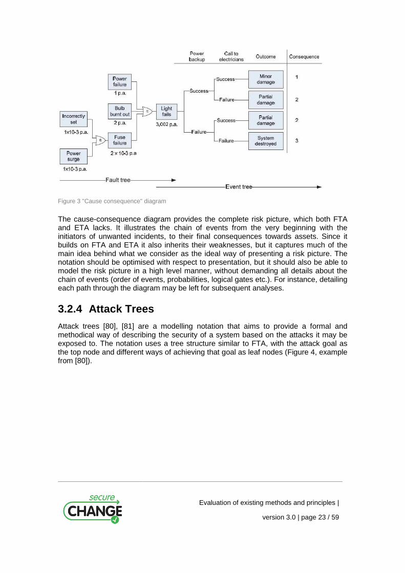
3.2.3 Cause-Consequence Diagrams
The cause-consequence diagram [71] combines the features of both fault tree and event tree. When constructing a cause-consequence diagram, the staring point is an unwanted incident. From this incident the diagram is developed backwards to find its causes (fault tree) and forwards to find its consequences (event tree). Figure 3 shows an example of a cause-consequence diagram.
Evaluation of existing methods and principles |
version 3.0 | page 23 / 59
Figure 3 "Cause consequence" diagram
The cause-consequence diagram provides the complete risk picture, which both FTA and ETA lacks. It illustrates the chain of events from the very beginning with the initiators of unwanted incidents, to their final consequences towards assets. Since it builds on FTA and ETA it also inherits their weaknesses, but it captures much of the main idea behind what we consider as the ideal way of presenting a risk picture. The notation should be optimised with respect to presentation, but it should also be able to model the risk picture in a high level manner, without demanding all details about the chain of events (order of events, probabilities, logical gates etc.). For instance, detailing each path through the diagram may be left for subsequent analyses.
3.2.4 Attack Trees
Attack trees [80], [81] are a modelling notation that aims to provide a formal and methodical way of describing the security of a system based on the attacks it may be exposed to. The notation uses a tree structure similar to FTA, with the attack goal as the top node and different ways of achieving that goal as leaf nodes (Figure 4, example from [80]).

Evaluation of existing methods and principles |
version 3.0 | page 24 / 59
Figure 4 Attack tree example
There exist an extension of attack trees called defence trees [9] which, in addition to representing attack strategies performed by an attacker, also represents the possibly countermeasures that may be implemented in the target system to mitigate the attacks. Since the notation is based on fault trees we get the same difficulties with respect to expressing logical gates, assigning likelihood/probability values to threat scenarios and computing precise likelihoods. Attack trees do however allow for less precise likelihood values (e.g. possible/impossible like in Figure 4), something which makes it easier to use for high-level analysis. Its focus is more on human behaviour than system behaviour since it represents different ways of attacking a system. In many cases it may be valuable to represent both how the system reacts to a security breach caused by a human, and a non-human source.
3.2.5 OCTAVE Threat Tree
The OCTAVE method for security analysis has its own tree notation which has much in common with event trees, but also fault trees. OCTAVE threat trees illustrate the source of an incident, the method and the motive behind the incident, which can be compared to fault trees. At the same time it illustrates the outcome of the incident that is more like an event tree. The OCTAVE threat tree can be seen as taking the tree notation one step closer to security risk analysis, in particular information security. The use of deliberate and accidental threats (in OCTAVE called motive) is for instance in accordance with ISO/IEC13335 Information security. Mixing two well established techniques like FTA and ETA in this way makes it more difficult to exploit the benefits from computerized FTA or ETA tools, and also conflicts with many analysis methods that recommend using these analysis techniques. The intention of adapting the tree notations to more security focused analysis by integrating security related concepts is however good.

Evaluation of existing methods and principles |
version 3.0 | page 25 / 59
3.2.6 Bayesian Networks
A Bayesian network [60], [62], [74], [78], [86], is a directed, acyclic graph. The intermediate nodes represent causes or contributing factors to the top node, which in Figure 5 is a “system failure” (taken from [74]). A Bayesian network is both a graphical and a probabilistic model that may be used to for instance predict the number of faults in a software component [33]. In Figure 5 the causes that contribute strongest to the event (A1-A3) are placed directly before the event. The causes are grouped into three categories: organisational factors, human factors and technical factors. When a Bayesian network is analysed quantitatively, each node holds a table with a probability distribution reflecting its parent nodes. For any manipulation of the probabilities of the nodes, the effects both forwards (towards child nodes and the top node) and backwards (towards parent nodes) can be computed [21]. A Bayesian network can be utilized both quantitatively and qualitatively. If the Bayesian network is analysed qualitatively, it provides relations between causes and effects. When analysed quantitatively, one uses its powerful mathematical model for computing probabilities, which is not only based on the probabilities for the leaf nodes like in fault trees, but also on intermediate nodes.
Figure 5 Example of a BN
3.2.7 Markov Diagrams
Markov analysis [43], [47], [58], is a stochastic mathematical analysis method that looks at sequences of events and analyses the tendency of which event that will be followed by another. Markov analysis may be used to analyse the reliability of systems that have a large degree of component dependencies. In contrast to FTA, Markov analysis does not assume complete component independence. It is also well suited to analyse systems that may partially fail or experience degraded states. A Markov analysis considers the system as a number of states, and transmissions between these states. The states are modelled graphically and statistical calculations are performed to determine the probability of each state transmission. Markov analysis is among others promoted by ISO/IEC61508. Markov models are more suitable for showing the

Evaluation of existing methods and principles |
version 3.0 | page 26 / 59
operation modes of a system where one may transit forth and back between states, than a chain of events of a security attack which is more likely to be a one way chain. Nevertheless, describing the operation modes of a system also includes describing the different barriers that should prevent an attack or reduce the consequences of an attack and for this purpose Markov analysis may be a useful tool. Using Markov analysis requires a well-specified system and may not be as suitable for high-level analyses.
Figure 6 Markov model
3.2.7.1 Riskit Graph
The Riskit method [59] includes a risk modelling technique based on a graph notation that makes it possible to specify factors that may influence a software development project. The Riskit method deals with project risks and has main focus on supporting software development organizations in developing their products. The evaluation and management of risks that might occur during the operation of software has therefore been left out [59] (p. 12). Riskit uses its own definitions inspired by for instance organisational strategy research [36]. A factor may be compared to a threat scenario, while the event is an unwanted incident. Reaction can be compared to consequence, and the effect set can be seen as a further detailing of the consequence. Riskit lacks threats, possibly because it unusual to consider deliberate harmful actions towards a software development project when assessing the project risk. It also lacks the notion of vulnerabilities.
3.2.8 CORAS Risk Modelling Language
The CORAS risk modelling language has been designed to support communication, documentation and analysis of security threat and risk scenarios. It was originally defined as a UML profile, and has later been customised and refined in several aspects, based on experiences from industrial case studies, and by empirical investigations. It consists of the graphical syntax of the CORAS diagrams, and a textual syntax and semantics translating the graphical elements into English [16].

Evaluation of existing methods and principles |
version 3.0 | page 27 / 59
Figure 7 CORAS threat diagram
CORAS threat diagrams are used during the risk identification and estimation phases of the CORAS risk analysis process (step 4 and 5; see Section 3.3.7). They describe how different threats exploit vulnerabilities to initiate threat scenarios and unwanted incidents, and which assets the unwanted incidents affect. A threat diagram organises this information in a directed acyclic graph, offering the same flexibility as cause-consequence diagrams and Bayesian networks, but using a graphical syntax that is more intuitive and easy to read. At the same time the semantics ensures that the translation of a diagram into English is unique.
CORAS diagrams were originally designed for qualitative analysis. Likelihood and consequence values are assigned directly by workshop participants during brainstorming sessions. However, the CORAS method provides a calculus [13] for computing likelihood and consequence values. The likelihood of a vertex may be deduced given the likelihood assigned to its parent vertices and the relations leading to it, and the likelihood of a vertex composed of several sub-vertices may be deduced from their likelihoods. The calculus is also used to checking the consistencies of assigned likelihood values.
3.2.9 Domain-Specific Modelling Language for Securi ty Analysis
The Security DSLM [69] was developed as part of the MODELPLEX project (EU, 034081). It consists of two diagram types, the Lite Diagram showing an overview, and the Detailed Diagram used for displaying detailed partial views of the model. The diagrams model security needs, risks and security objectives, defined in Section 3.3.8, and how they relate to the architecture of the system.
The main characteristic of the Lite Diagram is that it shows the entire model through a “filter” that lets us view only the architectural components. The purpose of this diagram is to show an un-detailed (or light) view of the model, in which the security information
Evaluation of existing methods and principles |
version 3.0 | page 28 / 59
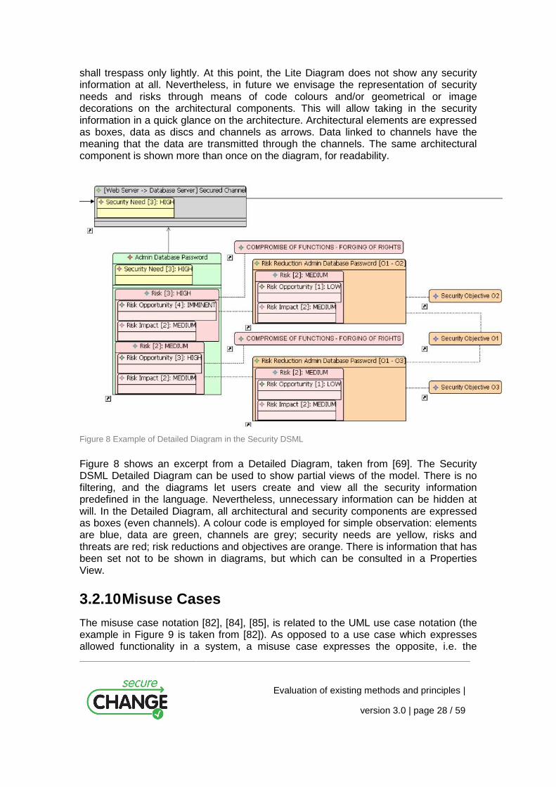
shall trespass only lightly. At this point, the Lite Diagram does not show any security information at all. Nevertheless, in future we envisage the representation of security needs and risks through means of code colours and/or geometrical or image decorations on the architectural components. This will allow taking in the security information in a quick glance on the architecture. Architectural elements are expressed as boxes, data as discs and channels as arrows. Data linked to channels have the meaning that the data are transmitted through the channels. The same architectural component is shown more than once on the diagram, for readability.
Figure 8 Example of Detailed Diagram in the Security DSML
Figure 8 shows an excerpt from a Detailed Diagram, taken from [69]. The Security DSML Detailed Diagram can be used to show partial views of the model. There is no filtering, and the diagrams let users create and view all the security information predefined in the language. Nevertheless, unnecessary information can be hidden at will. In the Detailed Diagram, all architectural and security components are expressed as boxes (even channels). A colour code is employed for simple observation: elements are blue, data are green, channels are grey; security needs are yellow, risks and threats are red; risk reductions and objectives are orange. There is information that has been set not to be shown in diagrams, but which can be consulted in a Properties View.
3.2.10 Misuse Cases
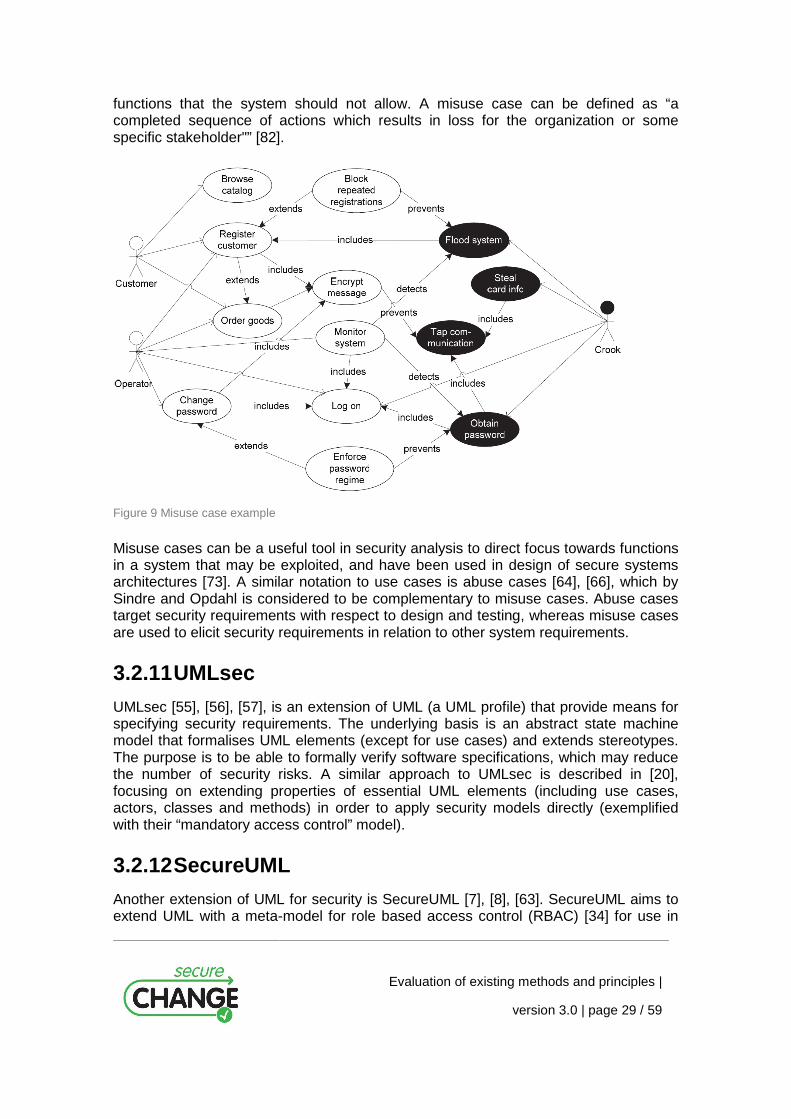
The misuse case notation [82], [84], [85], is related to the UML use case notation (the example in Figure 9 is taken from [82]). As opposed to a use case which expresses allowed functionality in a system, a misuse case expresses the opposite, i.e. the
Evaluation of existing methods and principles |
version 3.0 | page 29 / 59
functions that the system should not allow. A misuse case can be defined as “a completed sequence of actions which results in loss for the organization or some specific stakeholder"” [82].
Figure 9 Misuse case example
Misuse cases can be a useful tool in security analysis to direct focus towards functions in a system that may be exploited, and have been used in design of secure systems architectures [73]. A similar notation to use cases is abuse cases [64], [66], which by Sindre and Opdahl is considered to be complementary to misuse cases. Abuse cases target security requirements with respect to design and testing, whereas misuse cases are used to elicit security requirements in relation to other system requirements.
3.2.11 UMLsec
UMLsec [55], [56], [57], is an extension of UML (a UML profile) that provide means for specifying security requirements. The underlying basis is an abstract state machine model that formalises UML elements (except for use cases) and extends stereotypes. The purpose is to be able to formally verify software specifications, which may reduce the number of security risks. A similar approach to UMLsec is described in [20], focusing on extending properties of essential UML elements (including use cases, actors, classes and methods) in order to apply security models directly (exemplified with their “mandatory access control” model).
3.2.12 SecureUML
Another extension of UML for security is SecureUML [7], [8], [63]. SecureUML aims to extend UML with a meta-model for role based access control (RBAC) [34] for use in
Evaluation of existing methods and principles |
version 3.0 | page 30 / 59
model driven security engineering. The “Model Driven Security” approach is based on first specifying systems models and their security requirements and then use tools to generate the system architecture from these specifications. The approach combines system modelling and system security in a detailed level with particular focus on RBAC. RBAC is also targeted in [76] where the authors model the concept as reusable UML templates, more specifically by proposing a class diagram template for RBAC and use object diagram templates to specify RBAC constraints.
3.2.13 Microsoft’s Threat Modelling (DREAD)
In [40], [42], [89], Microsoft presents what they call threat modelling for software applications. The process involves defining threats to a system, ranking them according to their risk level, and finally choosing between different techniques of mitigating them. By using their threat model STRIDE, the risk analysis will be focused towards particular threat scenarios (i.e. Spoofing, Tampering, Repudiation, Information disclosure, Denial of Service, and Elevation of privilege). To support the process they make use of data flow diagrams [19], [36], to describe the target, and a kind of tree notation to rank risks (quite similar to attack trees). The threat modelling takes place in the design phase to help reveal potential risks, but it is also claimed to be helpful in code review and testing.
In [69], another method called threat modelling is presented. The process resembles [89] but claims that the sequence and description of steps is different and the execution of steps is extended to suit complex, networked systems. The threat modelling is used as a basis for defining security requirements to a system and consists of three steps:
1. Characterising the system.
2. Identifying assets and access points.
3. Identifying threats.
Only step 1 seems to involve modelling, the other two assess the models from step 1 using check lists for common threats, vulnerabilities, attack goals etc. Attack trees [80] are mentioned during threat identification, but only as an additional mean that may be used to support the process. The outcome of the process is a threat profile for the system that is used for security requirement elicitation.
The process presented in [91] is claimed to be a lightweight formal complement to Microsoft’s threat modelling approach. The process focuses on modelling functions, threats, and threat reducing efforts and then it checks the consistency between security threats and functions. Finally, it verifies the lack of threats in the refined model of indented functions and threats that have been mitigated. The process employs high level Petri nets (Predicate/Transition nets) [38], a formal method with both a graphical as well as a mathematical notation, often used to describe distributed systems.
3.2.14 The ProSecO Approach to Risk Modelling
In this section a description of the security meta-model that provides the relevant concepts for the security risk analysis of the ProSecO approach is given. Business objectives, security requirements and threats and security controls constitute security concepts that are defined in the Security Meta-Model (Figure 10) of the ProSecO

Evaluation of existing methods and principles |
version 3.0 | page 31 / 59
approach. Each element of the functional models and of the associated security models is associated with a state indicating the state of the security analysis process.
Figure 10 The ProSecO Security Meta-Model
At each point of time during the security analysis, the system is described by a set of interrelated model elements, where these model elements either adhere to the Functional Model or to the Security Model. We call each such set of interrelated model elements a Security Model.
The basic goal of the ProSecO approach is to support IT security management with a comprehensive process that integrates business and technical aspects. For this purpose business assets are modelled like business processes, organisational units, roles and information objects as well as the IT infrastructure on various layers of abstraction, with the intention to map their dependencies. This Functional System View describes the system at different levels of abstraction ranging from business processes to the functional and technical architecture. The elements of the Functional Model (e.g., business processes, information objects, components) drive the security analysis through their interrelations.
The goal of the Security Analysis Process is to attach the model elements of the Functional Model in a systematic way with security related information. Below the core security concepts and their interrelationships are presented. The ProSecO Security Meta-Model is shown in Figure 10. In this meta-model the class ModelElement represents any model element of the Functional Meta-models. More precisely, ModelElement is considered to be a supertype of all classes in the Functional Meta-models.
In the following the main concepts of the Security Meta Model are described:
– Security Objective: A Security Objective describes a general security goal to the system. Security Objectives in many cases originate in legal requirements and general availability, integrity and confidentiality requirements. For the purpose of the Security Analysis, Security Objectives are associated with model elements of the business layer (business processes or information types).

Evaluation of existing methods and principles |
version 3.0 | page 32 / 59
– Security Requirement: A Security Requirement is a detailed context-dependent explication of a Security Objective. It breaks a Security Objective down in several more detailed descriptions. The context of a Security Requirement is derived from the model element for which it is defined. Security Requirements are linked to Security Objectives to depict their paths of inheritance.
– Threat: A Threat is the description of an adverse event that is considered as potentially having a negative impact. A Threat by itself is not interesting for the analysis; it only becomes relevant if a targeted model element and a related security requirement is identified. Once the threat has been assessed and estimated regarding its impact, it becomes a risk.
– Risk: A Risk is therefore defined as a triplet consisting of a targeted model element, a related security requirement and a threat that potentially undermines the requirement. Risk is evaluated either quantitatively or qualitatively using an assessment of the impact and probability of the event. Moreover, every risk is evaluated in the context of the currently implemented security controls.
– Security Control: A Security Control is any measure or safeguard that has been put in place to mitigate the identified risks.
3.2.15 Tropos Goal-Risk Modelling
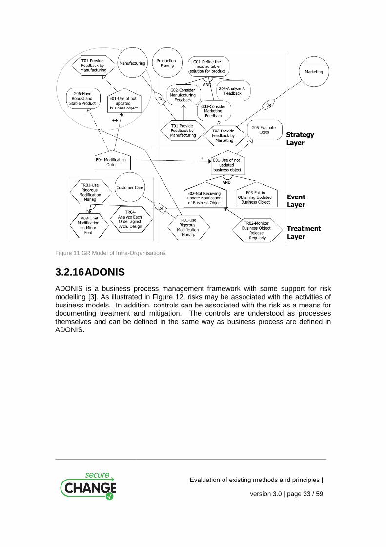
The Tropos Goal-Risk (GR) framework [4] is a formal framework that allows for tool-supported risk assessment and treatment selection. This framework extends the Tropos Goal Model [39] by adopting the idea of the three layers analysis introduced by Feather et al. [30] in their Defect Detection and Prevention (DDP) framework. These three layers, Strategy, Event and Treatment (see Figure 11), are used to reason about uncertain events that obstruct business goals, and to evaluate the effectiveness of treatments in mitigating such events.
The GR framework was initially developed for assessing the risks of single actors during early requirement analysis, but has been extended to assess and treat risks by considering also the interdependency among the actors within an organisation. Through this extension analysts can assess the risk perceived by each actor, taking into account the organisational environment where the actor acts. This provides a method assisting analysts in determining the treatments to be introduced in order to reach an acceptable risk level.
Evaluation of existing methods and principles |
version 3.0 | page 33 / 59
Figure 11 GR Model of Intra-Organisations
3.2.16 ADONIS
ADONIS is a business process management framework with some support for risk modelling [3]. As illustrated in Figure 12, risks may be associated with the activities of business models. In addition, controls can be associated with the risk as a means for documenting treatment and mitigation. The controls are understood as processes themselves and can be defined in the same way as business process are defined in ADONIS.

Evaluation of existing methods and principles |
version 3.0 | page 34 / 59
Figure 12 ADONIS support for risk modelling
3.3 Risk Analysis As explained in the introduction to Section 3.1, risk analysis is a process designed for identifying and describing the risk picture with respect to a target of analysis. Further, while risk management is a continuous and ongoing activity, risk analysis is an activity that terminates with a risk picture (and possible recommendations for treatments and mitigations) as the outcome. Most risk analysis methods follow more or less the risk analysis process shown in Figure 1, or a subset of it as in the case of risk assessment methods. However, most risk analysis methods include pragmatics; i.e. they instantiate the risk analysis process with techniques for e.g. risk identification and risk estimation and provide guidelines for how to carry out each of the activities of the risk analysis process. In this section we look at concrete risk analysis methods, as well as techniques for doing risk identification, estimation and evaluation.
Evaluation of existing methods and principles |
version 3.0 | page 35 / 59
3.3.1 Hazard and Operability Analysis (HazOp)
HazOp (Hazard and Operability) analysis [48] is a well known risk identification technique used in all forms for risk analyses. A HazOp is a structured brainstorming with the aim of finding ways system behaviour may deviate from design intention, and whether these deviations can lead to unwanted incidents (hazards). The participant must all have thorough knowledge of one or more aspects of the system analysed. The input to the analysis is system documentation of any kind, and in addition the analysis leader uses specialised guidewords to ensure that all aspects are covered. The guidewords are used in questions like “what if the service delivers too much data?”, “what if the service delivers too little data?”, “too slow response or too early?” and so on. This is meant to mitigate the weakness that the information gathered during a HazOp is restricted to the already existing knowledge within the group. The idea is that the guidewords can make people think of aspects they have not been thinking of before. A similar technique that is commonly used within safety analysis is called HazId (Hazard Identification). This is basically a simplified HazOp that uses checklists rather than guidewords, and it is often used early in the analysis process or for smaller risk analyses. HazOp can be tailored to fit any domain and system; for instance in [77] the method is especially targeting software. These kinds of methods represent particular suitable situations for using graphical security risk modelling languages since a common understanding and communication between the participants are crucial to the quality of the findings. Similar to FMEA/FMECA tables (see below), also HazOp tables are unsatisfactory for showing relationships between the findings (the different rows in the table). There is clearly a need for both documentation methods, where one keeps detailed information about each risk in tables while the relationships between the risks are documented graphically.
3.3.2 Failure Mode Effect Analysis/Failure Mode Eff ect and Criticality Analysis (FMEA/FMECA)
FMEA/FMECA (Failure Mode Effect Analysis/Failure Mode Effect and Criticality Analysis) [10] is a method that assess potential failures of individual components within a system. The method is usually conducted in two steps, first the failure modes and their effects are identified (FMEA). Then the failure modes are ranked according to their criticality and their probability (FMECA). The basis of the FMEA/FMECA is functional description of the system, where each component is analysed to identify all possible or failure modes and classify them according to their criticality. The FMEA/FMECA is a bottom-up approach especially suitable for detecting a system’s possible failure modes, and determining their consequences. The failure identification is normally organised as a brainstorming, structured by the system’s functional descriptions. The findings are documented in a table where each separate module’s potential failure modes are investigated with respect to failure detection method, failure effect and how critical it may be. It is not obvious how to document relations between failure modes in different modules, neither how the effects may be common for several modules. This is a common problem of tables, where relations between different rows are difficult to show. In this regard, a graphical language may be useful to document relations between the findings instead of, or in addition to the conventional FMEA/FMECA tables.
Evaluation of existing methods and principles |
version 3.0 | page 36 / 59
3.3.3 Operationally Critical Threat, Asset and Vulnerability Evaluation (OCTAVE)
OCTAVE (Operationally Critical Threat, Asset, and Vulnerability Evaluation) [2] is a risk based strategic assessment and planning technique for security. OCTAVE is conducted in three phases:
1. Identify critical assets and the threats to those assets.
2. Identify the vulnerabilities that expose the assets to threats.
3. Develop an appropriate treatment strategy.
Phase 1 normally involves two workshops, the first with senior management to define the scope of the analysis, and the second with staff that have a more technical expertise on the target of analysis. The workshops may have a form of a structured brainstorming where people with different competences and backgrounds participate. The intermediate findings are documented in tables and form the basis for developing asset-based threat profiles using a simple graphical tree-structure. The approach in OCTAVE is quite similar to the one used in the CORAS method for risk analysis (see Section 3.3.7).
3.3.4 CCTA Risk Analysis and Management Method (CRAMM)
CRAMM (CCTA Risk analysis and Management Method), is the UK Government’s Risk Analysis and Management Method [3]. It is owned by the UK government’s Security Service, but managed by Siemens/Insight (http://www.cramm.com). In CRAMM, risk analysis is identification and assessment of security risks while risk management is concerned with identifying appropriate countermeasures, or treatments for those risks.
Risk management according to CRAMM includes three phases:
1. Asset identification and valuation (including dependencies between assets).
2. Threat and vulnerability identification.
3. Treatment (countermeasure) identification.
The information is gathered through interviewing the owners of the assets, the users of the system, the technical support staff, and the security manager. In this manner, CRAMM is more like a review of the security of a product, conducted during system development or for an already running system. The documentation produced during a CRAMM review uses a standardized CRAMM format, mostly in the form of specialized tables. CRAMM may help an organisation to achieve compliance with ISO17799 [51], and the outcome is compliant with the mandatory documentation needed to achieve ISO27001 certification (BS7799-2) [13], [52]. The concepts and activities in CRAMM were a source of inspiration for the CORAS method for risk analysis (see Section 3.3.7).
Evaluation of existing methods and principles |
version 3.0 | page 37 / 59
3.3.5 Facilitated Risk Assessment Process (FRAP)
Facilitated Risk Assessment Process (FRAP) is developed by Peltier Associates (http://www.peltierassociates.com). A risk assessment according to FRAP focuses on security aspects of systems or business processes. The assessment team consists of representatives with competence on technical aspects, as well as business and management aspects. FRAP has focus on threats, vulnerabilities and consequences towards data integrity, confidentiality and availability. A risk assessment with FRAP consists of the following three phases:
– Pre-FRAP meeting: The objective of this meeting is to decide on the system description and scope of the assessment, as well as assembling an assessment team.
– The FRAP session: This phase consists of three activities: First, it is decided which roles each participant will have in the brainstorming session, reviews and agrees on the definitions and scope of the risk assessment. Second, a brainstorming to identify potential risks within the scope of the assessment id conduced. Third, the identified risks are prioritised according to how vulnerable the system is, and what impact the risks may have. When the risks are sufficiently specified, the participants may also suggest possible controls or treatments for the risks.
– The post-FRAP meeting(s): These meetings aim to further analyse the information gathered at the FRAP session. The outcome is an overview of risks and how they should be mitigated by existing or new controls (treatments). The final report contains a complete documentation of the process, including an action plan for the recommended treatments.
3.3.6 Strengths, Weaknesses, Opportunities and Threats (SWOT) Analysis
A SWOT analysis [44] is used to evaluate the Strengths, Weaknesses, Opportunities, and Threats associated with a project or business activity in a top-down manner. SWOT analysis is usually used in project or business planning, and the objective is to define a goal, strategy or actions, and find means to achieve it (e.g. increase income, reduce development time). In risk analysis it is used to get an initial overview of the risk picture and helps scoping the analysis to focus where it is most needed. In a risk analysis the objective of a SWOT will be to protect the assets within the target of analysis and then find:
1. Strengths: Attributes of the target that are helpful in protecting assets.
2. Weaknesses: Attributes of the target that are harmful to achieve sufficient protection of the assets.
3. Opportunities: External conditions that are helpful in protecting assets.
4. Threats: External conditions that are harmful to achieve sufficient protection of the assets.

Evaluation of existing methods and principles |
version 3.0 | page 38 / 59
A SWOT analysis takes form as a brainstorming session involving a cross-functional team consisting of people with different background and view of the target system. The information they come up with may be used as input to a more detailed risk analysis.
The findings are typically documented in various forms of table formats, adjusted to the particular need of the analysis, but often structured according to the four SWOT aspects. A risk focused SWOT analysis may benefit considerably from using an easily understandable graphical approach to model its findings. This will for instance make it possible to illustrate how a threat in one area may exploit a weakness in another, or how an opportunity may become a weakness if seen from a different point of view.
3.3.7 The CORAS Method for Risk Analysis
The CORAS method [11] is a model-based method for conducting risk analysis. It provides a customised language for threat and risk modelling (see Section 3.2.8), and comes with detailed guidelines explaining how the language should be used to capture and model relevant information during the various stages of the analysis. The Unified Modelling Language (UML) is typically used to model the target of the analysis. For documenting intermediate results and for presenting the overall conclusions, diagrams in the CORAS language are used. The CORAS method provides a computerised tool [16] designed to support documenting, maintaining and reporting analysis results through risk modelling.
In the CORAS method a risk analysis is conducted in seven steps:
– Step 1: The first step involves an introductory meeting. The main item on the agenda for this meeting is to get the representatives of the client to present their overall goals of the analysis and the target they wish to have analysed. Hence, during the initial step the analysts will gather information based on the client’s presentations and discussions.
– Step 2: The second step also involves a separate meeting with representatives of the client. However, this time the analysts will present their understanding of what they learned at the first meeting and from studying documentation that has been made available to them by the client. The second step also involves a rough, high-level security analysis. During this analysis the first threats, vulnerabilities, threat scenarios and unwanted incidents are identified. They will be used to help with directing and scoping the more detailed analysis still to come.
– Step 3: The third step involves a more refined description of the target to be analysed, and also all assumptions and other preconditions being made. Step three is terminated once all this documentation has been approved by the client.
– Step 4: This step is organised as a workshop, drawn from people with expertise on the target of the analysis. The goal is to identify as many potential unwanted incidents as possible, as well as threats, vulnerabilities and threat scenarios.
– Step 5: The fifth step is also organised as a workshop, this time with the focus on estimating consequences and likelihood values for each of the identified unwanted incidents.
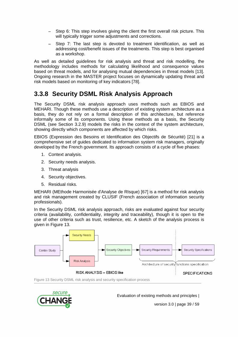
Evaluation of existing methods and principles |
version 3.0 | page 39 / 59
– Step 6: This step involves giving the client the first overall risk picture. This will typically trigger some adjustments and corrections.
– Step 7: The last step is devoted to treatment identification, as well as addressing cost/benefit issues of the treatments. This step is best organised as a workshop.
As well as detailed guidelines for risk analysis and threat and risk modelling, the methodology includes methods for calculating likelihood and consequence values based on threat models, and for analysing mutual dependencies in threat models [13]. Ongoing research in the MASTER project focuses on dynamically updating threat and risk models based on monitoring of key indicators [78].
3.3.8 Security DSML Risk Analysis Approach
The Security DSML risk analysis approach uses methods such as EBIOS and MEHARI. Though these methods use a description of existing system architecture as a basis, they do not rely on a formal description of this architecture, but reference informally some of its components. Using these methods as a basis, the Security DSML (see Section 3.2.9) models the risks in the context of the system architecture, showing directly which components are affected by which risks.
EBIOS (Expression des Besoins et Identification des Objectifs de Sécurité) [21] is a comprehensive set of guides dedicated to information system risk managers, originally developed by the French government. Its approach consists of a cycle of five phases:
1. Context analysis.
2. Security needs analysis.
3. Threat analysis
4. Security objectives.
5. Residual risks.
MEHARI (MEthode Harmonisée d'Analyse de RIsque) [67] is a method for risk analysis and risk management created by CLUSIF (French association of information security professionals).
In the Security DSML risk analysis approach, risks are evaluated against four security criteria (availability, confidentiality, integrity and traceability), though it is open to the use of other criteria such as trust, resilience, etc. A sketch of the analysis process is given in Figure 13.
Figure 13 Security DSML risk analysis and security specification process
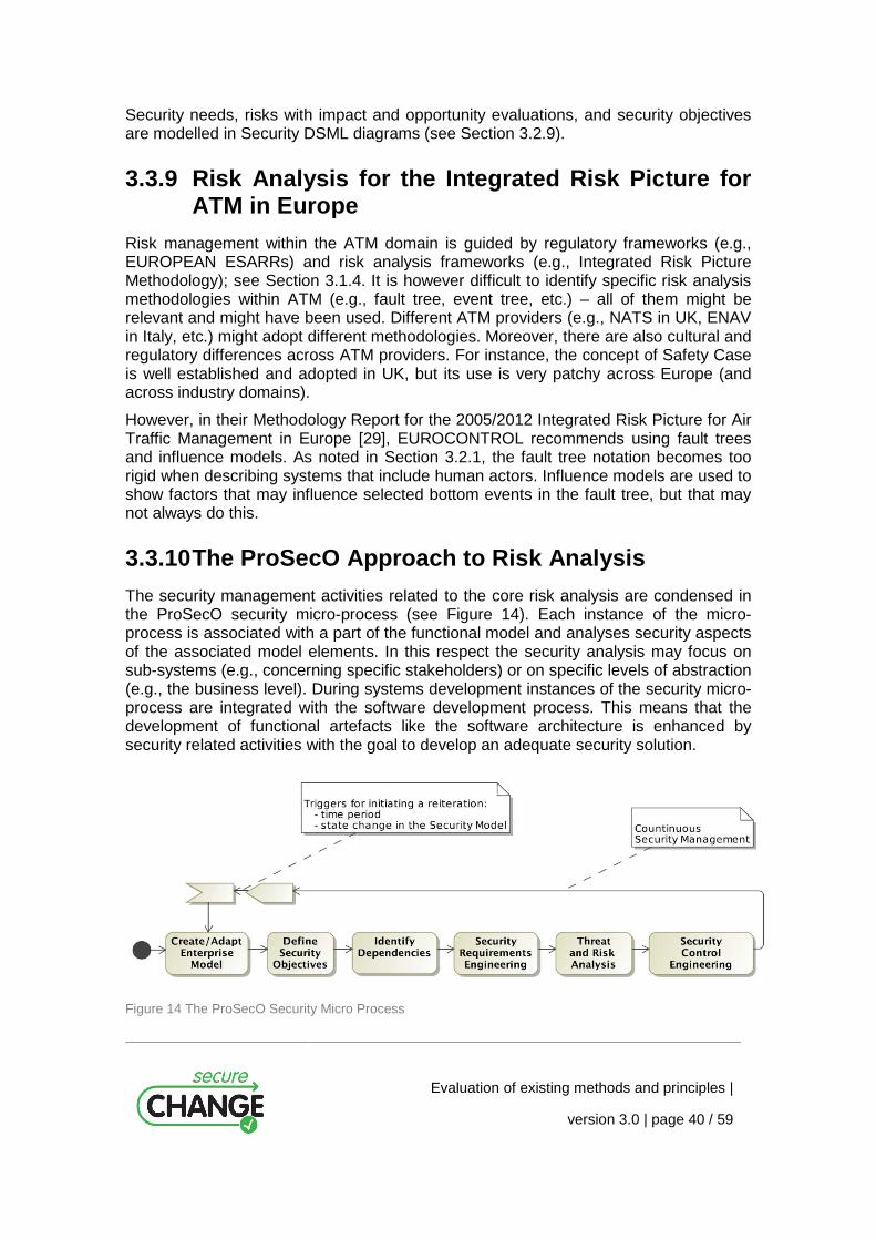
Evaluation of existing methods and principles |
version 3.0 | page 40 / 59
Security needs, risks with impact and opportunity evaluations, and security objectives are modelled in Security DSML diagrams (see Section 3.2.9).
3.3.9 Risk Analysis for the Integrated Risk Picture for ATM in Europe
Risk management within the ATM domain is guided by regulatory frameworks (e.g., EUROPEAN ESARRs) and risk analysis frameworks (e.g., Integrated Risk Picture Methodology); see Section 3.1.4. It is however difficult to identify specific risk analysis methodologies within ATM (e.g., fault tree, event tree, etc.) – all of them might be relevant and might have been used. Different ATM providers (e.g., NATS in UK, ENAV in Italy, etc.) might adopt different methodologies. Moreover, there are also cultural and regulatory differences across ATM providers. For instance, the concept of Safety Case is well established and adopted in UK, but its use is very patchy across Europe (and across industry domains).
However, in their Methodology Report for the 2005/2012 Integrated Risk Picture for Air Traffic Management in Europe [29], EUROCONTROL recommends using fault trees and influence models. As noted in Section 3.2.1, the fault tree notation becomes too rigid when describing systems that include human actors. Influence models are used to show factors that may influence selected bottom events in the fault tree, but that may not always do this.
3.3.10 The ProSecO Approach to Risk Analysis
The security management activities related to the core risk analysis are condensed in the ProSecO security micro-process (see Figure 14). Each instance of the micro-process is associated with a part of the functional model and analyses security aspects of the associated model elements. In this respect the security analysis may focus on sub-systems (e.g., concerning specific stakeholders) or on specific levels of abstraction (e.g., the business level). During systems development instances of the security micro-process are integrated with the software development process. This means that the development of functional artefacts like the software architecture is enhanced by security related activities with the goal to develop an adequate security solution.
Figure 14 The ProSecO Security Micro Process
Evaluation of existing methods and principles |
version 3.0 | page 41 / 59
The goal of the risk analysis is the identification of potential threats which could undermine a specific security requirement which is attributed to a specific functional model element (i.e. a system, a process, a role). To support the threat and risk analysis existing threat catalogues like the German IT-Grundschutz Catalogues [15] or EBIOS [21], Section 4 “Tools for assessing ISS risks” can provide valuable input in the identification of potential threats. Additional scenarios for incidents can stem from internal loss databases or collections of incidents from publicly announced security incidents [50].
After the identification of potential threats which could target functional model elements and their related security requirements, the resulting risk is assessed. Risks are assessed using either a qualitative assessment of their probability and impact or a quantitative assessment. In [12], a method using number of attacks and likelihood of propagation as a quantitative assessment approach is described.
3.3.11 Tropos Risk Assessment and Treatment
The Tropos risk assessment and treatment process is shown in Figure 15 (from [5]). The process is divided into the following four steps:
1. Goal operationalisation aims to analyse actors’ goals and the tasks used to achieve them. First, goals are identified. Actors may not be able to fully achieve their goals by themselves, so they can either appoint other actors to fulfil them entirely, or decompose them and assign part of them to other actors. Thus, goals are used as input for goal refinement or goal dependency. This phase also identifies the necessary means for achieving the goals.
2. Event operationalisation aims to analyse events and their impact on the strategy layer. First, the events relevant for the application domain are identified and depicted in the event layer. These are then analysed through refinement and contribution analysis. Finally, their impact over the strategy layer is described and their likelihood estimated. The framework allows analysts to model events with multi-impacts. This permits to do trade-off analysis when an event acts as a risk for some goals and as an opportunity for other goals.
3. Risk reasoning calculates the risk level perceived by each actor in the organisation.
4. Treatment operationalisation intends to refine the Goal-Risk model (see Section 3.2.14) in case the risk-level is higher than the risk acceptance defined by actors. First, treatments are identified along with their effect in mitigating the risks. Analysts need to ensure that treatments do not introduce any unacceptable negative influences over the strategy layer. To this end, contribution analysis is used to model the influences of treatments on the strategy layer.

Evaluation of existing methods and principles |
version 3.0 | page 42 / 59
Figure 15 Tropos risk assessment and treatment process
3.4 Change Management in Relation to Risk Management and Analysis
Change and configuration management, as well as maintenance of software systems and other kinds of systems, are broad fields of both research and applications. A thorough presentation and evaluation of these fields are clearly outside the scope of this report. We therefore restrict the presentation, and in this section existing approaches that see change management and maintenance in connection with risk analysis.
Evaluation of existing methods and principles |
version 3.0 | page 43 / 59
3.4.1 The ProSecO Approach
In the ProSecO approach change management is responsible for controlling all changes of elements of the security model. Changes are modelled by modifying the state of related security elements (see Figure 10). Each activity of the security process, e.g. adding new risks or adding new functional model elements, may lead to a state change of related elements in the Security Model. For example adding a security control that prevents a specific risk may lead to state changes of the respective risk and the related model elements.
Therefore the status changes of the security elements reflect the status and progress of the overall security management process. Reports and summaries of the status attributes can be used to govern the security management process and to identify tasks that still have to be accomplished by the domain owners. In addition state changes may trigger new risk analysis activities and propagate state changes along the dependency relations of the functional models. Consider for example a change to a specific security requirement. All the related threats and associated risks have to be re-assessed accordingly to reflect the change in the security requirement.
Using state attributes of the various elements of the security model, the goal is to identify and reflect changes such as security leaks, changed requirements (e.g., new legal regulations) or adapted configurations of the security architecture. Some state changes may require specific actions on a particular related model element denoting the responsible domain owner to accomplish the relevant tasks of the security process. For example if a new threat was attributed to a functional model element the respective domain owner is required to assess the related risks.
In the ProSecO approach possible changes are defined by the enumeration of different states of the elements of the security model. State machines reflect the possible states of the various elements of the security model and identify the allowed changes and actions and ensure that all changes are implemented in a controlled manner. In addition the different states and state changes have to fulfil certain constraints, which are also predefined.
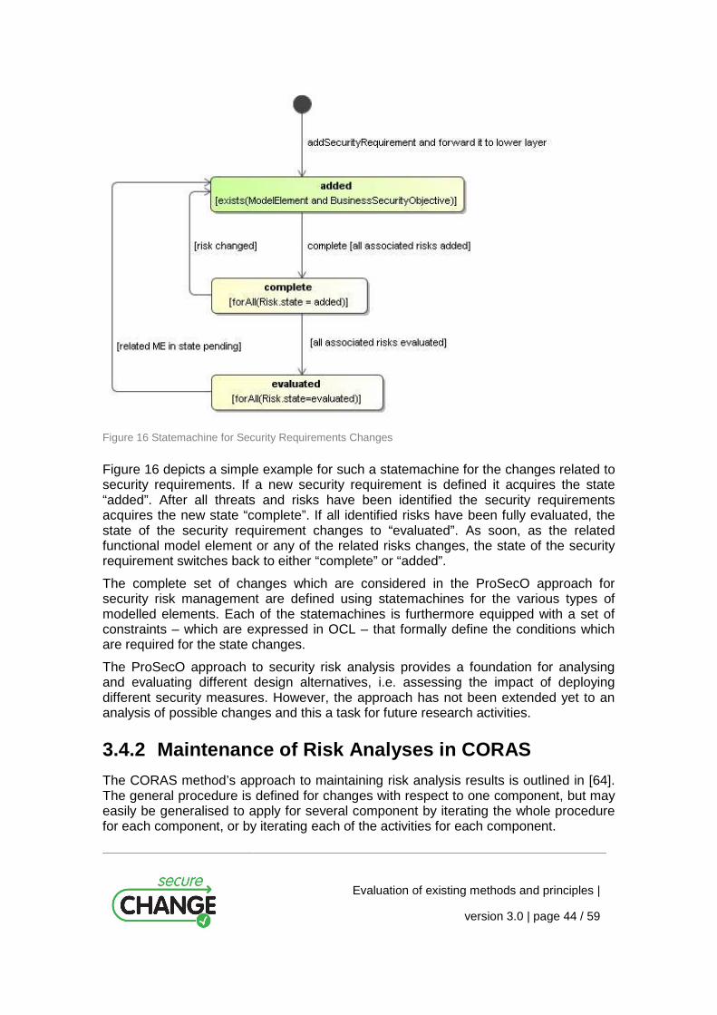
Evaluation of existing methods and principles |
version 3.0 | page 44 / 59
Figure 16 Statemachine for Security Requirements Changes
Figure 16 depicts a simple example for such a statemachine for the changes related to security requirements. If a new security requirement is defined it acquires the state “added”. After all threats and risks have been identified the security requirements acquires the new state “complete”. If all identified risks have been fully evaluated, the state of the security requirement changes to “evaluated”. As soon, as the related functional model element or any of the related risks changes, the state of the security requirement switches back to either “complete” or “added”.
The complete set of changes which are considered in the ProSecO approach for security risk management are defined using statemachines for the various types of modelled elements. Each of the statemachines is furthermore equipped with a set of constraints – which are expressed in OCL – that formally define the conditions which are required for the state changes.
The ProSecO approach to security risk analysis provides a foundation for analysing and evaluating different design alternatives, i.e. assessing the impact of deploying different security measures. However, the approach has not been extended yet to an analysis of possible changes and this a task for future research activities.
3.4.2 Maintenance of Risk Analyses in CORAS
The CORAS method’s approach to maintaining risk analysis results is outlined in [64]. The general procedure is defined for changes with respect to one component, but may easily be generalised to apply for several component by iterating the whole procedure for each component, or by iterating each of the activities for each component.
Evaluation of existing methods and principles |
version 3.0 | page 45 / 59
The procedure is built around the contents of three sets:
– PAA: The set of possibly affected assets.
– AA: The set of affected assets.
– AR: The set of affected risks.
The procedure is outlined in the following (C refers to the component to be maintained):
1. Update system description. The system description, i.e., the system documentation, must be updated to reflect the changes.
2. Update description of the target of analysis. The target description is a subset of the system description and must be updated accordingly. The target for a risk analysis may only be a certain part or feature of the component in question. Hence, the first step when maintaining a risk analysis is to check whether the changes are within the target of analysis. If they are not, the existing analysis carries over unchanged.
3. Identify PAA. The set of assets that may be affected by C are identified. Although a change is within the target of analysis, it does not have to be of relevance for any of the identified assets. If there are no affected assets, the original risk analysis can be kept.
4. Update assets analysis (re-evaluate ranking). PAA potentially consists of two kinds of assets: assets for which risk analysis results already exists and new assets. New assets must be ranked and “old” assets must be re-evaluated taking the changes into consideration.
5. Update threats and vulnerabilities (identify AA). All assets in PAA must be analysed with respect to threats and vulnerabilities. There may be new threats and vulnerabilities, vulnerabilities may no longer be relevant, or the change may indicate that frequency and consequence values have changed. If any of this applies, or the asset is new, has received a new rank, or has become irrelevant, then the asset is added to AA. The relevant vulnerabilities and any new threats must be recorded for further analysis. As in Step 3, if AA is empty, then the original risk analysis can be kept.
6. Update unwanted incidents (identify AR). Now only the assets in AA are considered. The threats and vulnerabilities that were noted in Step 5 must be analysed with respect to relevance for any new or earlier identified unwanted incidents. New unwanted incidents must be documented. Risk related to affected unwanted incidents and new unwanted incidents are added to AR.
7. Analyse, evaluate and treat AR. All risks in AR are analysed, evaluated and treated in accordance with the risk analysis process and the risk analysis documentation is updated accordingly.
Comparing these steps to the steps of the CORAS method (see Section 3.3.7), Steps 1–4 update the information gathered in the introductory phase (Steps 1–3), Steps 5 and 6 update the risk identification (Step 4), and Step 7 update the risk estimation, evaluation and treatment (Steps 5–7).

Evaluation of existing methods and principles |
version 3.0 | page 46 / 59
3.4.3 Other Approaches
While change in risk management is not yet thoroughly researched, searching for literature on change in risk management turns some relevant papers. The extent to which these papers are concerned with integrating change in risk analysis, and maintenance of risk analysis results, is however limited. While some papers are concerned with dealing proactively with risks introduced by system changes, in some cases, such as [40], the system is merely reanalysed. Other papers, such as [61], analyses in what way change in itself is a risk, and how change affects the security of a system.
A more promising approach is presented in [82], where Susan A. Sherer presents an approach to using risk analysis to manage software maintenance. The main process of updating a risk analysis may be summarised by the following questions:
1. Does the change eliminate any risks? If yes, remove them.
2. Does the change add any new risks? If yes, add them, including risk estimation.
3. Does the change affect the user’s or the system’s ability to prevent the consequences of risks? If yes, update consequence estimates.
This approach would still demand a revision of the previous analysis, but it focuses on how the risk picture responds to changes in the system.

Evaluation of existing methods and principles |
version 3.0 | page 47 / 59
4 Evaluation
In this section we evaluate the state-of-the-art described in the previous section with respect to the criteria identified in Section 2. The evaluation follows the same structure as the criteria: In Section 4.1 we evaluate with respect to language, in Section 4.2 with respect to method, in Section 4.3 with respect to documentation framework and in Section 4.4 with respect to tool.
4.1 Language Several (but far from all) of the languages investigated have some support for associating elements of risk models to parts of the target description (L1.2).
– UML based approaches such as mis-use cases may utilize built in mechanisms in the UML for relating elements from different UML diagram, or a suitable profile for doing so may be defined.
– In the Thales DSML, architectural components and (security) information are modelled and both security needs and risks are associated with these components. Risk reduction components are related to risks and security objectives. This means that risks are related to parts of the target, but it is at the cost of not having relations between risks and other elements of risk analysis.
– In ProSecO, risks are related to elements of a functional model of the target. In addition the model elements are related to security objective and security requirements and risks are related to threats and security controls (for treatment and mitigation).
– Tropos is mainly a language for modelling and decomposition of goals. Events (unwanted incidents) may be related to the goals, and the events may be decomposed similar to the top event of a fault three. In addition, treatments, represented as tasks, can be associated with the events of the event threes.
– CORAS has support for modularizing risk models, which means that each module of the model may be associated with a part of the target description.
– In ADONIS, risks can be associated with the activities of a business model.
The only approach with some support for modelling states, states or phases of a change (L2.1) is ProSecO. All elements of a ProSecO security model (security objectives, security requirements, functional elements and risks) have a state which gives the status of the element. When the models change, elements of the model may be transferred to states that indicate that additional risk analysis is needed. ProSecO also gives some support to modelling of the change process (L2.2) by means of state machines that define the state changes of the elements of the security model.
Several languages exist for modelling of processes in general (e.g. UML, SPEM, BPML), but are not presented in this deliverable. We can still assume that they to some degree may be applied for modelling of change processes (L2.2). However, the only

Evaluation of existing methods and principles |
version 3.0 | page 48 / 59
approach we are aware of that allows you to assign risk related information to the processes (L2.3) is ADONIS.
None of the languages for risk modelling investigated have any support for defining an evolving risk picture or for incorporating time into the risk models (L3.x); structurally they are all every static. Some of them, however, provide support for updating qualitative values annotated to the diagrams, in the sense that by changing the input values, the derived output values can be automatically updated. These languages include fault threes, Markov models, Bayesian networks and the CORAS language.
4.2 Method In the state-of-the-art we find some methodological support for handling of changes and maintenance in relation to risk analysis:
– The CORAS method provides guidelines for identifying parts of risk analysis documentation affected by changes and for maintaining risk analysis documentation (M1.2 & M1.3).
– The ProSecO provides guidelines for relating risk analysis documentation to target descriptions, for identifying parts of the risk analysis documentation affected by changes, and for identifying parts of the target in need for additional risk analysis in the face of change (M1.1, M1.2 & M1.3)
However, both approaches are restricted to component-based systems and system descriptions, and to discrete changes.
The CORAS method also provides a calculus than can be applied to update risk values is a risk model (M3.5), but the model itself is static. The same is true for some of the other risk analysis methods such as fault trees, Bayesian networks and Markov models.
4.3 Documentation Framework Support for some of the requirements to the documentation framework is found among the approached to risk management investigated. In particular, the ProSecO approach provides support for documentation of target descriptions (D1.1), documentation of risk analyses (D1.2) and relating target descriptions with risk analysis documentation (traceability) (D1.3). ProSecO also has some support for specifying change processes (using state machines) and relating them to the target and risk models (D2.1 & D2.2). In addition, ADONIS provides some support for documenting risks to stages of a process (D2.3).
Support for documentation of risk analysis of different stages of a change process (D2.4) or support for documentation of evolving targets (D3.1) and evolving or hierarchical risk models (D3.2 & D3.3), we have not found within the state-of-the-art.
Evaluation of existing methods and principles |
version 3.0 | page 49 / 59
4.4 Tool There exists tool support for several of the approaches evaluated in this report. However, because the state-of-the-art only provide partial support for the success criteria defined for language, method and documentation framework, the same will be true with respect to tool. There is possibly some support for some of the criteria (T1.1, T1.2 & T2.2) in the ProSecO approach, and current work on the CORAS method in other project will possibly result in tool support for automated or semi-automated calculations on risk levels in risk models. Except from this, it is difficult to see any real support for our success criteria for tools.

Evaluation of existing methods and principles |
version 3.0 | page 50 / 59
5 Conclusions
The four main innovations of Work Package 5 of the SecureChange project will be a language, a method, a documentation framework and a tool supporting risk analysis of evolving systems. In this report we have provided a classification that characterises three perspectives (maintenance/a posteriori, before-after/a priori and continuous perspective) and four kinds of changes (changes to target, environment assumptions, scope and knowledge) that are relevant for risk analysis.
Based on the perspectives, success criteria for each of the main innovations are defined, and these criteria are used to evaluate existing methods and principles. This evaluation showed that the state-of-the-art provides partial support for the criteria defined for the maintenance/a posteriori perspective, little but some support for the before-after/a priori perspective, and almost no support for the continuous perspective. On the other hand, the continuous perspective is the most general and interesting – it might even be that the other two perspectives can be considered special cases of the continuous perspective – and it is support for the continuous perspective that should be our goal in the project.
For the reminder of this section, we draw conclusions with respect to each of the main innovations/artefacts to be developed in the work package.
5.1 Language Risk modelling languages exists that provide some support for doing risk analysis of changes in the maintenance perspective and the before-after perspective. This is not a surprise, as doing two risk analyses and making two risk pictures, one “before picture” and one “after picture” is always an options. For the continuous perspective, however, very little support was found.
The most flexible and expressive of the risk modelling languages is probably the CORAS language. We therefore expect the future work in Work package 5 to be based on this language. The CORAS language, however, lacks the relations to the target models, as well as a number of other features specified in the success criteria, and in the development of the language we should incorporate principles from the other approaches such as the relations from risk to other elements of a security model in ProSecO and the relations from risks to activities of processes in ADONIS.
5.2 Method Among the risk analysis methods evaluated in this report, the CORAS method seems to be the most complete, while the ProSecO approach seems to be one with the most explicit support for handling changes. The work on defining a method for risk analysis for evolving systems should probably look to both of these approaches as starting points for the work. Further, the work should profit on earlier and ongoing work on change and maintenance within these two approaches.
Evaluation of existing methods and principles |
version 3.0 | page 51 / 59
5.3 Documentation Framework In the state-of-the-art evaluated in this report, the ProSecO risk management is the only approach that provides support for documentation of changes in risk analyses. The approach is restricted in scope, and a more elaborate and expressive meta-model is needed for the documentation framework to be developed. Still, the work on defining the documentation framework should probably look to the principles of ProSecO as a starting point. In addition, it will probably be necessary to look into general repository technology.
5.4 Tool The tool support of a language or a method is obviously very dependent on the properties of the language, method, etc. it is implementing. In this early stage in the project, when the language and method of Work Package 5 are still unspecified, it is difficult to draw any strong conclusions with respect to development of the tool. This means the evaluation with respect to tool and technologies must be reiterated at a later time when the other artefacts of the work package have been specified. We do, however, believe that both the ProSecO and the CORAS approaches will be worth looking at when we come to this point.
Evaluation of existing methods and principles |
version 3.0 | page 52 / 59
Appendix: Glossary
Terminology is not consistently applied within the field of risk management and risk analysis. For this reason, the terminology used in the various approaches presented in this report might also be somewhat inconsistent. We have, however, strived at keeping the terminology consistent at least in the general parts of the report. In this glossary, we provide the definitions we apply, for a number of central concepts in risk analysis.
Target: The target of the analysis is the system, organisation, enterprise, etc., or parts thereof, that is the subject of the risk analysis.
Scope: The scope of the analysis is the extent or range of the analysis; the scope defines the border of the analysis, i.e. what is held inside of and what is held outside of the analysis.
Focus: The focus of the analysis is the main issue or central area of attention in the risk analysis; the focus is within the scope of the analysis.
Environment: The environment of the target is the surrounding things of relevance that may affect or interact with the target; in the most general case, the rest of the world.
Context: The context of the analysis is the premises for and background of the analysis; this includes the purposes of the analysis and to whom the analysis is addressed.
Assumptions: The assumptions of the analysis are what we take as granted or accept as true (although they may not be so); the assumptions may be about the target and about the environment; the results of the analysis are valid only under these assumptions.
Target description: The target description is a description of the target including its focus, scope, environment and assumptions; only the parts or aspects of the environment that are relevant for the target and the analysis are included in the target description.
Party: An organisation, company, person, group or other body on whose behalf the risk analysis is conducted.
Asset: Something to which a party assigns value and hence for which the party requires protection.
Indirect asset: An asset the harm to which is completely determined by the harm to other assets with respect to the target of analysis.
Direct asset: An asset that is not indirect.
Threat: A potential cause of an unwanted incident.
Threat scenario: A chain or series of events that is initiated by a threat and that may lead to an unwanted incident.

Evaluation of existing methods and principles |
version 3.0 | page 53 / 59
Vulnerability: A weakness, flaw or deficiency that opens for, or may be exploited by, a threat to cause harm to or reduce the value of an asset.
Unwanted incident: An event that harms or reduces the value of an asset.
Likelihood: The frequency or probability of something to occur.
Consequence: The impact of an unwanted incident on an asset in terms of harm or reduced asset value.
Risk: The likelihood of an unwanted incident and its consequence for a specific asset.
Risk level: The level or value of a risk as derived from its likelihood and consequence.
Treatment scenario: The implementation, operationalisation or execution of appropriate measures to reduce risk level.
Treatment category: A general approach to treating risks; the categories are avoid, reduce consequence, reduce likelihood, transfer and retain.

Evaluation of existing methods and principles |
version 3.0 | page 54 / 59
References
[1] AIChE, “Guidelines for Chemical Process Quantitative Risk Analysis”, American Institute of Chemical Engineers, Center for Chemical Process Safety, 1989.
[2] Alberts, C., J., and Dorofee, A. J., “OCTAVE Criteria Version 2.0”, Tech. report CMU/SEI-2001-TR-016. ESC-TR-2001-016, 2001.
[3] ADONIS. “Risk management and compliance with ADONIS: Community Edition”.
[4] Asnar, Y. and Giorgini, P., “Modelling Risk and Identifying Countermeasures in Organizations”. In Proc. of CRITIS ’06, LNCS 4347, pages 55–66. Springer, 2006.
[5] Asnar, Y., Moretti, R., Sebastianis, M., and Zannone, N., “Risk as Dependability Metrics for the Evaluation of Business Solutions: A Model-driven Approach”, ARES, pp.1240-1247, 2008 Third International Conference on Availability, Reliability and Security, 2008.
[6] Barber, B. and Davey, J., “The Use of the CCTA Risk Analysis and Management Methodology CRAMM in Health Information Systems”, in Proc. MEDINFO'92, pp. 1589-1593, 1992.
[7] Basin, D., Doser, J., and Lodderstedt, T., “Model Driven Security for Process-Oriented Systems”, in Proc. 8th ACM symposium on Access control models and technologies (SACMAT'03), pp. 100-110, 2003.
[8] Basin, D., Doser, J., and Lodderstedt, T., “Model Driven Security: from UML Models to Access Control Infrastructures”, ACM Transactions on Software Engineering and Methodology, vol. 15 (1), pp. 39-91, 2006.
[9] Bistarelli, S., Fioravanti, F., and Peretti, P., “Defence tree for economic evaluations of security investment”, in Proc. 1st Int. Conference on Availability, Reliability and Security (ARES'06), pp. 416-423, 2006.
[10] Bouti, A. and Kadi, A. D., “A state-of-the-art review of FMEA/FMECA”, International Journal of Reliability, Quality and Safety Engineering, vol. 1, pp. 515-543, 1994.
[11] den Braber, F., Hogganvik, I., Lund, M. S., Stølen, K., and Vraalsen, F. “Model-based security analysis in seven steps – a guided tour to the CORAS method”. BT Technology Journal, 25(1):101-117, January 2007.
[12] Breu, R., Innerhofer-Oberperfler, F., and Yautsiukhin, A., “Quantitative assessment of enterprise security system”. International Workshop on Privacy and Assurance. In Proceedings of ARES 2008, pp. 921-928, 2008.
[13] Brændeland, G., Dahl, H. E. I., and Stølen, K. “A modular approach to the modelling and analysis of risk scenarios with mutual dependencies”. Technical report A8360, SINTEF ICT, 2008.
[14] BS7799-2, Information Security Management Systems - Specification with guidance for use (replaced by ISO27001): British Standards Institute (BSI), 1999.
Evaluation of existing methods and principles |
version 3.0 | page 55 / 59
[15] BSI (Federal Office for Information Security), “IT-Grundschutz Catalogues”, Version 2005, URL: http://www.bsi.bund.de/english/gshb/download/index.htm 2005.
[16] The CORAS Method, http://coras.sourceforge.net/, retrieved 22/6-09.
[17] Dahl, H. E. I. and Hogganvik, I., and Stølen, K. “Structured semantics for the CORAS security risk modelling language#. Technical report STF07 A970, SINTEF Information and Communication Technology, 2007.
[18] DCSSI (Direction centrale de la sécurité des systèmes d'information), “EBIOS: Expression des Besoins et Identification des Objectifs de Sécurité. Section 4. Tools for Assessing ISS Risks”, Version 2.0, 2004.
[19] Demarco, T. and Plauger, P. J., “Structured Analysis and Systems specification”, Prentice-Hall, 1979.
[20] Doan, T., Demurjian, S., Ting, T. C., and Ketterl, A., “MAC and UML for Secure Software Design”, in Proc. ACM Workshop on Formal Methods in Security Engineering (FMSE'04), pp. 75-85, 2004.
[21] EBIOS – Expression of Needs and Identification of Security Objectives, http://www.ssi.gouv.fr/en/confidence/ebiospresentation.html, retrieved 23/6-09.
[22] Edwards, E., “Man and machine: Systems for safety”, in Proc. British Airline Pilots Associations Technical Symposium, British Airline Pilots Associations, pp. 21–36, 1972.
[23] ESARR Advisory Material/Guidance Document (EAM/GUI), EAM 4/GUI 1, Explanatory Material on ESARR 4 Requirements, Edition 2.0, 2005.
[24] ESARR Advisory Material/Guidance Document (EAM/GUI), EAM 4/GUI 2, ESARR 4 and Related Safety Oversight, Edition 4.0, 2006.
[25] EUROCONTROL safety regulatory requirements (ESARR), ESARR 4 – risk assessment and mitigation in ATM, Edition 1.0, 2001.
[26] EUROCONTROL safety regulatory requirements (ESARR), ESARR 6 – Software in ATM Systems, Edition 1.0, 2003.
[27] EUROCONTROL, 2004 Baseline Integrated Risk Picture for Air Traffic Management in Europe, EEC Note No. 15/05, 2005.
[28] EUROCONTROL, Main Report for the 2005/2012 Integrated Risk Picture for Air Traffic Management in Europe, EEC Note No. 05/06, 2006.
[29] EUROCONTROL, Methodology Report for the 2005/2012 Integrated Risk Picture for Air Traffic Management in Europe, 2006.
[30] Feather, M. S., Cornford, S. L., Hicks, K. A., and Johnson, K. R. “Applications of Tool Support for Risk-Informed Requirements Reasoning”. CSSE, 20(1), 2005.
[31] Fenton, N. and Neil, M., “Combining evidence in Risk Analysis using Bayesian Networks”. Agena White Paper, W0704/01, v01.01, 2004.
Evaluation of existing methods and principles |
version 3.0 | page 56 / 59
[32] Fenton, N. and Ohlsson, N., “Quantitative Analysis of Faults and Failures in a Complex Software System”, IEEE Transactions on Software Engineering, vol. 26, 2000.
[33] Fenton, N., Krause, P., and Neil, M., “Software Measurement: Uncertainty and Causal Modeling”, IEEE Software, vol. 19 (4), pp. 116-122, 2002.
[34] Ferraiolo, D. F., Sandhu, R., Gavrila, S., Kuhn, D. R., and Chandramouli, R., “Proposed NIST standard for role-based access control”, ACM Transactions on Information System Security (TISSEC), vol. 4 (3), pp. 224-274, 2001.
[35] Seehusen, F. and Stølen, K. “Graphical specification of dynamic network structure”, in Proc. Seventh International Conference on Enterprise Information Systems (ICEIS 2005), volume 3, pp. 203-210, INSTICC Press, 2005.
[36] Freeman, R. E., Strategic Management: A Stakeholder Approach: Ballinger Publishing, 1984.
[37] Gane, C. and Sarson, T., Structured Systems Analysis: Tools and Techniques: McDonnell Douglas Information, 1977.
[38] Genrich, H. J., “Predicate/transition nets”, in Advances in Petri Nets vol. LNCS 254-255, W. Brauer, W. Resig, and G. Rozenberg, Eds.: Springer-Verlag, 1987, pp. 207-247.
[39] Giorgini, P., Mylopoulos, J., and Sebastiani, R. “Goal-Oriented Requirements Analysis and Reasoning in the Tropos Methodology”. EAAI, 18(2):159–171, 2005.
[40] Goel, S., and Chen, V. “Can business process reengineering lead to security vulnerabilities: Analyzing the reengineered process”. International Journal of Production Economics, 115 (1): 104-112, 2008.
[41] Howard, M. and LeBlanc, D., Writing Secure Code, 2 ed, Microsoft Press, 2003.
[42] Howard, M. and Lipner, S., The Security Development Lifecycle, Microsoft Press, 2006.
[43] Howard, R. A., Dynamic Probabilistic Systems: Volume 1, Markov models: John Wiley & Sons, 1971.
[44] Humprey, A., “SWOT - Strengths, Weaknesses, Opportunities, Threats”, Stanford University, 1960-1970.
[45] IEC60300-3-9, Dependability management - Part 3: Application guide - Section 9: Risk analysis of technological systems - Event Tree Analysis (ETA), 1995.
[46] IEC61025, Fault Tree Analysis (FTA), 1990.
[47] IEC61165, Application of Markov techniques, 1995.
[48] IEC61882, Hazard and operability studies (HAZOP studies) - Application guide, 2001.
[49] Innerhofer-Oberperfler, F. and Breu, R. “Using an Enterprise Architecture for IT Risk Management”. In Proc. of ISSA'06: Information Security South Africa Conference, 2006.
[50] Innerhofer-Oberperfler, F. and Breu, R., “An empirically derived loss taxonomy based on publicly known security incidents”, in Proc. ARES/CISIS 2009, Fukuoka, Japan, 2009.
Evaluation of existing methods and principles |
version 3.0 | page 57 / 59
[51] ISO/IEC17799, Information technology – Security techniques – Code of practice for information security management (ISO27002), 2005.
[52] ISO27001, Information technology – Security techniques – Information security management systems – Requirements, 2005.
[53] Johnson, W. G., MORT Safety Assurance Systems, Marcel Dekker, 1980.
[54] Jøsang, A., Bradley, D., and Knapskog, S. J., “Belief-Based Risk Analysis”, in Proc. Australasian Information Security Workshop 2004 (AISW'04), (32), pp. 63-68, 2004.
[55] Jürjens, J., “Sound Methods and Effective Tools for Model-based Security Engineering with UML”, in Proc. Int. Conference on Software Engineering (ICSE'05), pp. 322-331, 2005.
[56] Jürjens, J., "UMLsec: Extending UML for secure systems development", in Proc. UML 2002 - The Unified Modeling Language, (LNCS 2460), pp. 412-425, 2002.
[57] Jürjens, J., Secure Systems Development with UML, Springer, 2005.
[58] Kemeny, J. G. and Snell, J. L., Finite Markov chains, Springer-Verlag, 1976.
[59] Kontio, J., “Software Engineering Risk Management: A Method, Improvement Framework, and Empirical Evaluation”, in Dept. of Computer Science and Engineering: Helsinki University of Technology, 2001.
[60] Krause, P. and Clark, D., Representing Uncertain Knowledge: An Artificial Intelligence Approach, Intellect Press, 1993.
[61] Lee, E., Park, Y., and Shin, J. G. “Large engineering project risk management using a Bayesian belief network”. Expert Syst. Appl. 36, 3 (Apr. 2009), 5880-5887.
[62] Lindley, D. V., Introduction to Probability and Statistics from a Bayesian Viewpoint, Cambridge University Press, 1965.
[63] Lodderstedt, T., Basin, D., and Doser, J., “SecureUML: A UML-Based Modeling Language for Model-Driven Security”, in Proc. UML'02, LNCS, (2460), pp. 426-441, 2002.
[64] Lund, M. S., den Braber, F., and Stølen, K. “Maintaining results from security assessments”, in Proc. Seventh European Conference on Software Maintenance and Reengineering (CSMR 2003), pp. 341-350, IEEE Computer Society, 2003.
[65] McDermott, J. and Fox, C., “Using abuse case models for security requirements analysis”, in Proc. 15th Computer Security Applications Conference (ACSAC’99), pp. 55-66, 1999.
[66] McDermott, J., "Abuse-case-based assurance arguments", in Proc. 17th Computer Security Applications Conference (ACSAC'O1), pp. 366-374, 2001.
[67] MEHARI: Information risk analysis and management methodology, https://www.clusif.asso.fr/en/production/mehari/, retrieved 23/6-09.
[68] Microsoft, “The Security Risk Management Guideline”, Microsoft Solutions for Security and Compliance, Microsoft Security Centre of Excellence, 2006.

Evaluation of existing methods and principles |
version 3.0 | page 58 / 59
[69] MODELPLEX deliverable D3.3.g: “DSML for security analysis”, 2009.
[70] Myagmar, S., Lee, A. J., and Yurcik, W., “Threat Modeling as a Basis for Security Requirements”, in Proc. Symposium on Requirements Engineering for Information Security (SREIS'05), 2005.
[71] Nielsen, D. S., “The Cause/Consequence Diagram Method as a Basis for Quantitative Accident Analysis”, Danish Atomic Energy Commission, RISO-M-1374, 1971.
[72] NIST, “Risk Management Guide for Information Technology Systems”, U.S. National Institute of Standards and Technology (NIST), NIST Special Publication SP800-30, 2002.
[73] Pauli, J. and Xu, D., “Threat-driven architectural design of secure information systems”, in Proc. 7th International Conference on Enterprise Information Systems (ICEIS’05), pp. 136-143, 2005.
[74] Perrow, C., Normal accidents: living with high-risk technologies, Princeton University Press, 1999.
[75] Rausand, M. and Høyland, A., System reliability Theory: Models, Statistical Methods, and Applications, 2 ed, Wiley, 2004.
[76] Ray, I., Li, N., France, R., and Kim, D.-K., ”Using UML To Visualize Role-Based Access Control Constraints”, in Proc. SACMAT'04, pp. 115-124, 2004.
[77] Redmill, F., Chudleigh, M., and Catmur, J., HAZOP and Software HAZOP: Wiley, 1999.
[78] Refsdal, A. and Stølen, K. “Employing key indicators to provide a dynamic risk picture with a notion of confidence”, to appear in proc. IFIP Trust Management 2009, Springer, 2009.
[79] Savage, L. J., The Foundations of Statistical Inference, J. Wiley, 1962.
[80] Schneier, B., “Attack trees: Modeling security threats”, Dr. Dobb's Journal, vol. 24 (12), pp. 21-29, 1999.
[81] Schneier, B., Secrets & Lies: Digital Security in a Networked World, John Wiley & Sons, 2000.
[82] Sherer, S. A., “Using risk analysis to manage software maintenance”, Journal of Software Maintenance, vol. 9 (6), pp. 345-364, 1997.
[83] Sindre, G. and Opdahl, A. L., “Capturing Security Requirements through Misuse Cases”, in Proc. 14th Norwegian Informatics Conference (NIK'2001), pp. 219-230, 2001.
[84] Sindre, G. and Opdahl, A. L., “Eliciting Security Requirements by Misuse Cases”, in Proc. TOOLS-PACIFIC, pp. 120-131, 2000.
[85] Sindre, G. and Opdahl, A. L., “Templates for Misuse Case Description”, in Proc. Workshop of Requirements Engineering: Foundation of Software Quality (REFSQ'01), pp. 125-136, 2001.
[86] Spiegelhalter, D. J., “Probabilistic reasoning in predictive expert systems”, in Proc. 2nd Annual Conference on Uncertainty in Artificial Intelligence (UAI'86), pp. 47-67, 1986.

Evaluation of existing methods and principles |
version 3.0 | page 59 / 59
[87] Stålhane, T. and Wedde, K. J., “Practical experience with the application of HazOp to a software intensive system”, in Proc. Joint ESCOM and ENCRESS Conference, pp. 271-281, 1998.
[88] Standards Australia, Standards New Zealand. “Australian/New Zealand Standard. Risk Management, 2004”. AS/NZS 4360:2004.
[89] Swiderski, F. and Snyder, W., Threat Modeling, Microsoft Press, 2004.
[90] West, S. and Andrews, A. D., “OCTAVE-Best Practices Comparative Analysis”, Prepared for U.S. Army Medical Research and Materiel Command, ATI IPT Technical Report 03-4, 2003.
[91] Xu, D. and Nygard, K., “A Threat-Driven Approach to Modeling and Verifying Secure Software”, in Proc. Int. Conference on Automated Software Engineering (ASE'05), pp. 342-346, 2005.