Embed Size (px)
Citation preview
PHAROS (606982) D4.1
D4.1 Satellite-based Messaging Uplink for In-Situ
Sensors Specification
Instrument Collaborative Project
Call / Topic FP7-SPACE-2013-1 / SPA.2013.1.2-01
Project Title Project on a Multi-Hazard Open Platform for Satellite Based Downstream Services
Project Number 606982
Project Acronym PHAROS
Project Start Date 01/12/2013
Project Duration 30 months
Contributing WP WP 4; Task 4.1
Dissemination Level PU
Contractual Delivery Date M15
Actual Delivery Date 01/03/2015
Editor M.A. Marchitti (DLR)
Contributors M. A. Marchitti, J. Mulero Chaves (DLR), R. Campo, F. Collard (EUT), K. Jäckel, H. Podolski (IQWIRE)
PHAROS (606982) D4.1
Document History
Version Date Modifications Source
0.1 01/08/2014 First draft including the ToC DLR
0.2 31/10/2014 Inputs to Section 4 (first draft); first inputs to Section 2; ToC update
DLR
0.3 19/01/2015 Input to Section 3 and 5 IQWIRE
0.4 27/01/2015 Input to Section 3.2 EUT
0.5 04/02/2015 Requirements review EUT
0.6 09/02/2015 Update to Section 3.3 and 5 IQWIRE
0.7 09/02/2015 Sections 4 and 3.4 EUT
0.8 20/02/2015 Version for QA DLR
0.9 24/02/2015 QA reviewed version AVA
1.0 01/03/2015 First Issue DLR
01/03/2015 i
PHAROS (606982) D4.1
Table of Contents
List of Figures ........................................................................................................................ iv
List of Tables .......................................................................................................................... v
List of Acronyms .................................................................................................................... vi
Executive Summary .............................................................................................................. 1
1 Introduction .................................................................................................................... 2
2 Technical Requirements ................................................................................................. 3
2.1 Functional Requirements......................................................................................... 4
2.2 Interfacing Requirements ........................................................................................ 6
2.3 Non-Functional Requirements ................................................................................. 7
3 Reference Scenario ........................................................................................................ 9
3.1 Sensor Networks Solutions ....................................................................................11
3.1.1 Physical and technological description ............................................................11
3.1.2 High level description and integration - Sensor Observation Service ...............14
3.2 Communication Networks Solutions .......................................................................16
3.2.1 Satellite based solutions ..................................................................................16
3.2.2 Terrestrial based solutions ..............................................................................20
3.3 The FireWatch System ...........................................................................................21
3.3.1 Fire Detection Principles .................................................................................21
3.3.2 System Overview and Performance of FireWatch ...........................................22
3.3.3 Role within the PHAROS system.....................................................................26
3.4 The satellite system solution ..................................................................................29
4 F-SIM Protocol Specification .........................................................................................31
4.1 F-SIM general description ......................................................................................31
4.2 Functional system architecture using F-SIM protocol .............................................32
4.3 Functional terminal architecture using F-SIM protocol ............................................33
4.4 F-SIM physical layer adaptation from S-MIM ..........................................................35
4.4.1 Higher flexibility through new physical configurations ......................................35
4.4.2 Specific Adaptations from S-MIM ....................................................................36
4.5 F-SIM link layer description ....................................................................................37
4.5.1 Logon procedure .............................................................................................38
4.5.2 F-SIM signalling ..............................................................................................39
4.5.3 Power control ..................................................................................................39
4.6 F-SIM demodulation process ..................................................................................39
4.7 F-SIM performance ................................................................................................41
01/03/2015 ii

PHAROS (606982) D4.1
5 Interfaces ......................................................................................................................42
5.1 FireWatch and F-SIM integration ............................................................................42
5.2 FireWatch Interface ................................................................................................43
6 Conclusions ...................................................................................................................45
7 References ....................................................................................................................46
01/03/2015 iii
PHAROS (606982) D4.1
List of Figures
Figure 3-1: PHAROS Long Term System Architecture Diagram ............................................ 9
Figure 3-2: Reference Scenario ............................................................................................10
Figure 3-3: General interfacing of sensors and actuators to control networks (adapted from [7]) ........................................................................................................................................11
Figure 3-4: Sensor and actuator interface node (adapted from [9]) .......................................12
Figure 3-5: ISO layers of a fully IP sensor network ...............................................................13
Figure 3-6: Example sensor network based on Ethernet I/F and IP protocol for world wide access (adapted from [11]) ...................................................................................................14
Figure 3-7: SOS GetObservation Example ...........................................................................15
Figure 3-8: Prototype of an OGC-conformant temperature sensor .......................................16
Figure 3-9: O&M XML listing temperature sensor (extract) ..................................................16
Figure 3-10: Satellite Network architecture ...........................................................................17
Figure 3-11: Smoke detection behind horizon line ................................................................22
Figure 3-12: Detection range as a function of cloud size and visibility ..................................23
Figure 3-13: System elements ..............................................................................................23
Figure 3-14: Dataflow within the Firewatch System ..............................................................24
Figure 3-15: FireWatch Alert message .................................................................................25
Figure 3-16: Satellite system integrated in PHAROS ............................................................29
Figure 4-1: F-SIM System Functional Architecture ...............................................................32
Figure 4-2: IST Functional Architecture ................................................................................34
Figure 4-3: F-SIM spreading and modulation ........................................................................35
Figure 4-4: Demodulation process ........................................................................................40
Figure 4-5: F-SIM performances ...........................................................................................41
Figure 5-1: FireWatch Network with additional sensors ........................................................44
01/03/2015 iv
PHAROS (606982) D4.1
List of Tables
Table 2-1: Technical Requirement specification template ...................................................... 3
Table 2-2: Development Levels ............................................................................................. 4
Table 3-1: SOS mandatory requests ....................................................................................14
Table 3-2: Satellite solutions comparison .............................................................................19
Table 3-3: Terrestrial solutions comparison ..........................................................................21
Table 3-4: SP Events and Observations service specification ..............................................27
Table 3-5: SP-SG Sensor Events specification (elements) ...................................................28
Table 3-6: SG-SP Alert specification ....................................................................................28
Table 4-1: Differences between S-MIM and F-SIM ...............................................................31
Table 4-2: requirements to be satisfied by the terminal output signal phase noise mask ......37
Table 5-1: possible F-SIM configurations, when a burst length of 1513 B is selected ...........43
Table 5-2: Summary of sensor messages characteristics, when a specific F-SIM configuration is selected (Bandwidth 10MHz, info byte/burst 1513 B, burst duration 75 ms) .43
Table 5-3: Interface Properties Summary .............................................................................44
01/03/2015 v
PHAROS (606982) D4.1
List of Acronyms
3GPP 3rd Generation Partnership Project
AB Advisory Board
AD/DA Analog-to-digital/digital-to-analog
ADSL Asymmetric Digital Subscriber Line
ARQ Automatic Repeat Request
BACnet Building Automation and Control Networks
CAPEX Capital Expenditures
CCD Charged Coupled Device
DLR Deutschen Zentrums für Luft- und Raumfahrt – German Aerospace Center
DSL Digital Subscriber Line
DVB Digital Video Broadcasting
DVB-S2 Digital Video Broadcasting – Second Generation
EDGE Enhanced Data rates for GSM Evolution
EIRP Equivalent Isotropical Radiated Power
ESA European Space Agency
ESRI Environmental System Research Institute
ESSA Enhanced Spread Spectrum Aloha
EoC Ethernet-over-Coax
ETSI European Telecommunications Standards Institute
F-SIM Fixed Satellite Interactive Messaging
FDD Frequency Division Duplexing
FL Forward Link
G/T Figure of merit
GEO Geostationary Earth Orbit
GSM Global System for Mobile Communications
GPRS General packet radio service
GUI Graphical User Interface
HD High Definition
HSDPA Highs Speed Downlink Packet Access
HSPA Highs Speed Packet Access
01/03/2015 vi
PHAROS (606982) D4.1
HSUPA Highs Speed Uplink Packet Access
HTS High Throughput Satellite
HTTP Hypertext Transfer Protocol
IDU Indoor Unit
IF Infrared
IMU Interactive satellite terminal Monitoring Unit
IP Internet Protocol
IPS Internet Protocol Suite
IR Infrared
IST Interactive Satellite Terminals
JSON JavaScript Object Notation
JPEG Joint Photographic Experts Group
LAN Local Area Network
LIDAR Light detection and ranging
LL Link Layer
LTE Long Term Evolution
LEO Low Earth Orbit
LNB Low Noise Block
LonWorks Local operating network
M2M Machine to Machine
MAC Media Access Control
MATLAB Matrix Laboratory
MBED Platform and operating system for internet-connected devices
MEO Medium Earth Orbit
ModBus Serial communication protocol
MSS Maximum Segment Size
NCR Network Clock Reference
NOC Network Operating Center
ODU Outdoor Unit
OFMD Ortogonal Frequency Division Multiplexing
OGC Open Geospatial Consortium
OPEX Operating Expense
01/03/2015 vii

PHAROS (606982) D4.1
OVSF Orthogonal variable spreading factor
PCCH Physical Control Channel
PDCH Physical Data Channel
PDU Packet Data Unit
PHAROS Project on a Multi-Hazard Open Platform for Satellite Based Downstream Services
PLL Phase Locked Loop
PLR Packet Loss Ratio
QoS Quality of Service
RL Return Link
RLE Return Link Encapsulator
RF Radio Frequency
RX Receiver
ROLIS Rosetta Lander Imaging System
SAT SSA Access Table
SCADA Supervisory Control and Data Acquisition
SCT SSA Configuration Table
SCU Satellite terminal Control Unit
SDYT SSA Dynamic Table
SF Spreading Factor
SFD Saturation Flux Density
SG Service Gateway
SHP ESRI Shape File
S-MIM S-band Mobile Interactive Multimedia
SOS Sensor Observation Service
SP Service Platform
SSA Spread Spectrum Aloha
STB Set-top-box
SWE Sensor Web Enablement
TCP Transmission Control Protocol
TX Transmitter
TDMA Time Division Multiple Access
TFI Transport Format Indication
01/03/2015 viii
PHAROS (606982) D4.1
UWB Ultra Wide Band
UMTS Universal Mobile Telecommunications System
UTRAN Universal Terrestrial Radio Access Network
VHF Very High Frequency
VSAT Very Small Aperture Terminal
WCDMA Wideband Code Division Multiple Access
WiFi WLAN
WiMax Worldwide Interoperability for Microwave Access
WLAN Wireless Local Area Network
XML Extensible Markup Language
Z-Wave Wireless communications protocol for home automation
ZigBee Wireless mesh network standard
01/03/2015 ix

PHAROS (606982) D4.1
Intentionally blank
01/03/2015 x
PHAROS (606982) D4.1
Executive Summary This deliverable presents the specification for the satellite based uplink for in-situ sensor data. The main task contributing to this deliverable is Task 4.1 (Satellite-based uplink for in-situ sensor data) which started in month 7 and is planned to finish in month 24. The main motivation behind introducing a satellite link to interface sensor networks to the service platform is to be found in the additional resilience that such a link would provide, and the strategic relevance that this represents in a context such as PHAROS.
The objectives of task 4.1 are drawn as follows:
• Review the F-SIM standard, in particular the parts that deal with the random access return link, according to the requirement of the PHAROS applications.
• Realise and evaluate a data interface between the terrestrial FireWatch system and the prototype satellite terminal. To do this, a deep understanding of the FireWatch as selected in-situ sensor network to be used during the PHAROS short term approach has been necessary.
• Implement the required adaptations at the satellite prototype terminal as well as at the hub.
• Identify CAPEX and OPEX.
The work performed to specify the PHAROS overall system architecture, described in D2.9 [1], the set of requirements and the system engineering process documented in D2.5 [2] have been used as a basis for the present deliverable. Moreover, the outcome of the Advisory Board (AB) and end user workshop held in Barcelona, in October 2014, has highlighted two important things that have taken into account for preparing the document: (i) the importance of providing a system able to integrate different available sensor networks, (the importance of meteorological data was highlighted) which has led to broaden the discussion within the task and extend it to analyse the scenario from a higher level perspective which included different sensor networks and (ii) the possibility of using communication systems alternative to the satellite one on which the task is focused that may be possibly considered for the long term approach.
Additionally, during the first discussions which took place at the beginning of the task, it was decided by the involved partners (in Task 4.1 as well as in Task 2.2 – Service sustainability and business plan) not to document the identified CAPEX and OPEX in the current deliverable, but to include them in D2.2 [3] (draft) and D2.3 [4] (final version). The rationale behind this decision is the fact that the overall analysis of the CAPEX and OPEX for the whole system and for each of its modules is planned to be carried out within the context of Task 2.2 and must be documented in the Task 2.2-related documents. Therefore, to avoid duplication of this information, it seems to be reasonable to perform the complete analysis in a unique document where all related information can be found, rather than providing an independent section within this document. This decision does not have any impact in the time and working plan, since both activities run in parallel and the submission of the deliverables related to each of them is planned for the same point in time.
01/03/2015 1
PHAROS (606982) D4.1
1 Introduction The deliverable reflects the work carried out in the framework of Task 4.1 and presents the specification of the satellite based up-link used for connecting in-situ networks with the PHAROS service platform. In particular, the adaption which is required to adapt the S-MIM (S-band Mobile Interactive Multimedia) standard to be operated in Ka-band and the rationale behind the employment of a different standard, F-SIM, to operate this link, is presented.
The document describes the reference scenario taken into account for this task, describing the different components while moving from a general to particular perspective. The document analyses different communication alternatives which might be used to interconnect in-situ sensor networks to the service platform and describes the particularities of the chosen satellite solution. Thereafter, focusing on the satellite solution, the F-SIM protocol used for the transmission of data from the sensor network to the platform is described, while finally, a description of the interfaces to interconnect the in-situ sensor network with the satellite terminal is provided.
The specification contained in this deliverable will serve as basis for the implementation to be carried out within the task, while any variation with respect to the specification will be documented in D4.2 (to be submitted in November 2015).
The document is structured as follows:
• Section 2 presents the technical requirements identified to trigger the design of this corresponding module and which will be the basis for the implementation phase. The technical requirements identified in the document have been derived from the system requirements specified in D2.5 [2].
• Section 3 outlines the reference scenario used for the provided analysis. Moreover, the in-situ sensor network solutions that have been considered and all the possible communication solutions that may be used to interconnect the sensor networks and the service platform are described, highlighting the ones that will be considered in the PHAROS short term approach.
• Section 4 presents in detail the F-SIM protocol specification. In particular, it describes how the F-SIM physical layer has been adapted based on S-MIM and gives an account of the F-SIM link layer and the protocol’s performance.
• Section 5 intends to detail the interfaces between the FireWatch system and the satellite terminal, glancing at problematics that may arise from the integration between FireWatch and F-SIM.
• Finally, Section 6 provides the conclusions of the document.
01/03/2015 2
PHAROS (606982) D4.1
2 Technical Requirements This section presents a description of the technical requirements to be fulfilled by the satellite-based messaging uplink to interconnect the in-situ sensors with the PHAROS service platform.
These requirements are based on the user and system requirements firstly identified in Deliverable D2.4 [5] and later reviewed and documented in Deliverable D2.5 [2]. In order to allow tracking these technical requirements during the implementation of the specified system module after the submission of the present document, a working copy of them is included in D2.5 [2] to allow further revisions of the requirements and track their status in the next issues of the document (D2.6, to be submitted in November 2015, and D2.7, to be submitted in May 2016).
Technical requirements have been defined classifying them according to the following categories:
• Functional requirements: these are the requirements related to the functionalities identified for the satellite-based messaging uplink.
• Interfacing requirements: these requirements are focused on the capability of the system module to interconnect with the other system elements.
• Non-functional requirements: related to qualitative features to be provided by the satellite-based uplink, rather than on the functionalities to be provided.
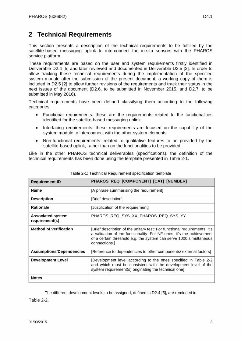
Like in the other PHAROS technical deliverables (specifications), the definition of the technical requirements has been done using the template presented in Table 2-1.
Table 2-1: Technical Requirement specification template
Requirement ID PHAROS_REQ_[COMPONENT]_[CAT]_[NUMBER]
Name [A phrase summarising the requirement]
Description [Brief description]
Rationale [Justification of the requirement]
Associated system requirement(s)
PHAROS_REQ_SYS_XX, PHAROS_REQ_SYS_YY
Method of verification [Brief description of the unitary test: For functional requirements, it’s a validation of the functionality. For NF ones, it’s the achievement of a certain threshold e.g. the system can serve 1000 simultaneous connections.]
Assumptions/Dependencies [Reference to dependencies to other components/ external factors]
Development Level [Development level according to the ones specified in Table 2-2 and which must be consistent with the development level of the system requirement(s) originating the technical one]
Notes
The different development levels to be assigned, defined in D2.4 [5], are reminded in
Table 2-2.
01/03/2015 3
PHAROS (606982) D4.1
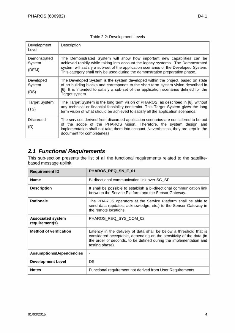
Table 2-2: Development Levels
Development Level
Description
Demonstrated System
(DEM)
The Demonstrated System will show how important new capabilities can be achieved rapidly while taking into account the legacy systems. The Demonstrated system will satisfy a sub-set of the application scenarios of the Developed System. This category shall only be used during the demonstration preparation phase.
Developed System
(DS)
The Developed System is the system developed within the project, based on state of art building blocks and corresponds to the short term system vision described in [6]. It is intended to satisfy a sub-set of the application scenarios defined for the Target system.
Target System
(TS)
The Target System is the long term vision of PHAROS, as described in [6], without any technical or financial feasibility constraint. This Target System gives the long term vision of what should be achieved to satisfy all the application scenarios.
Discarded
(D)
The services derived from discarded application scenarios are considered to be out of the scope of the PHAROS vision. Therefore, the system design and implementation shall not take them into account. Nevertheless, they are kept in the document for completeness
2.1 Functional Requirements This sub-section presents the list of all the functional requirements related to the satellite-based message uplink.
Requirement ID PHAROS_REQ_SN_F_01
Name Bi-directional communication link over SG_SP
Description It shall be possible to establish a bi-directional communication link between the Service Platform and the Sensor Gateway.
Rationale The PHAROS operators at the Service Platform shall be able to send data (updates, acknowledge, etc.) to the Sensor Gateway in the remote locations.
Associated system requirement(s)
PHAROS_REQ_SYS_COM_02
Method of verification Latency in the delivery of data shall be below a threshold that is considered acceptable, depending on the sensitivity of the data (in the order of seconds, to be defined during the implementation and testing phase).
Assumptions/Dependencies -
Development Level DS
Notes Functional requirement not derived from User Requirements.
01/03/2015 4
PHAROS (606982) D4.1
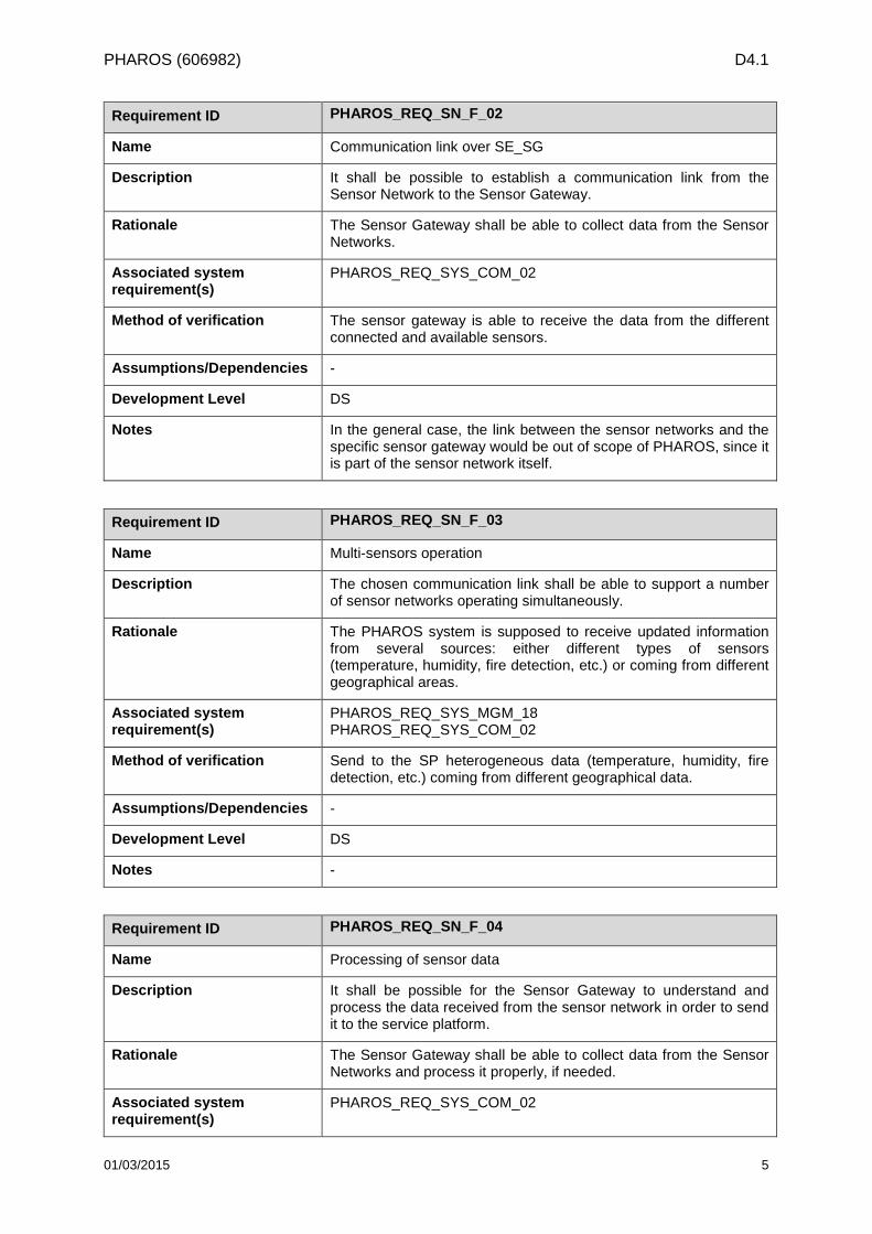
Requirement ID PHAROS_REQ_SN_F_02
Name Communication link over SE_SG
Description It shall be possible to establish a communication link from the Sensor Network to the Sensor Gateway.
Rationale The Sensor Gateway shall be able to collect data from the Sensor Networks.
Associated system requirement(s)
PHAROS_REQ_SYS_COM_02
Method of verification The sensor gateway is able to receive the data from the different connected and available sensors.
Assumptions/Dependencies -
Development Level DS
Notes In the general case, the link between the sensor networks and the specific sensor gateway would be out of scope of PHAROS, since it is part of the sensor network itself.
Requirement ID PHAROS_REQ_SN_F_03
Name Multi-sensors operation
Description The chosen communication link shall be able to support a number of sensor networks operating simultaneously.
Rationale The PHAROS system is supposed to receive updated information from several sources: either different types of sensors (temperature, humidity, fire detection, etc.) or coming from different geographical areas.
Associated system requirement(s)
PHAROS_REQ_SYS_MGM_18 PHAROS_REQ_SYS_COM_02
Method of verification Send to the SP heterogeneous data (temperature, humidity, fire detection, etc.) coming from different geographical data.
Assumptions/Dependencies -
Development Level DS
Notes -
Requirement ID PHAROS_REQ_SN_F_04
Name Processing of sensor data
Description It shall be possible for the Sensor Gateway to understand and process the data received from the sensor network in order to send it to the service platform.
Rationale The Sensor Gateway shall be able to collect data from the Sensor Networks and process it properly, if needed.
Associated system requirement(s)
PHAROS_REQ_SYS_COM_02
01/03/2015 5
PHAROS (606982) D4.1
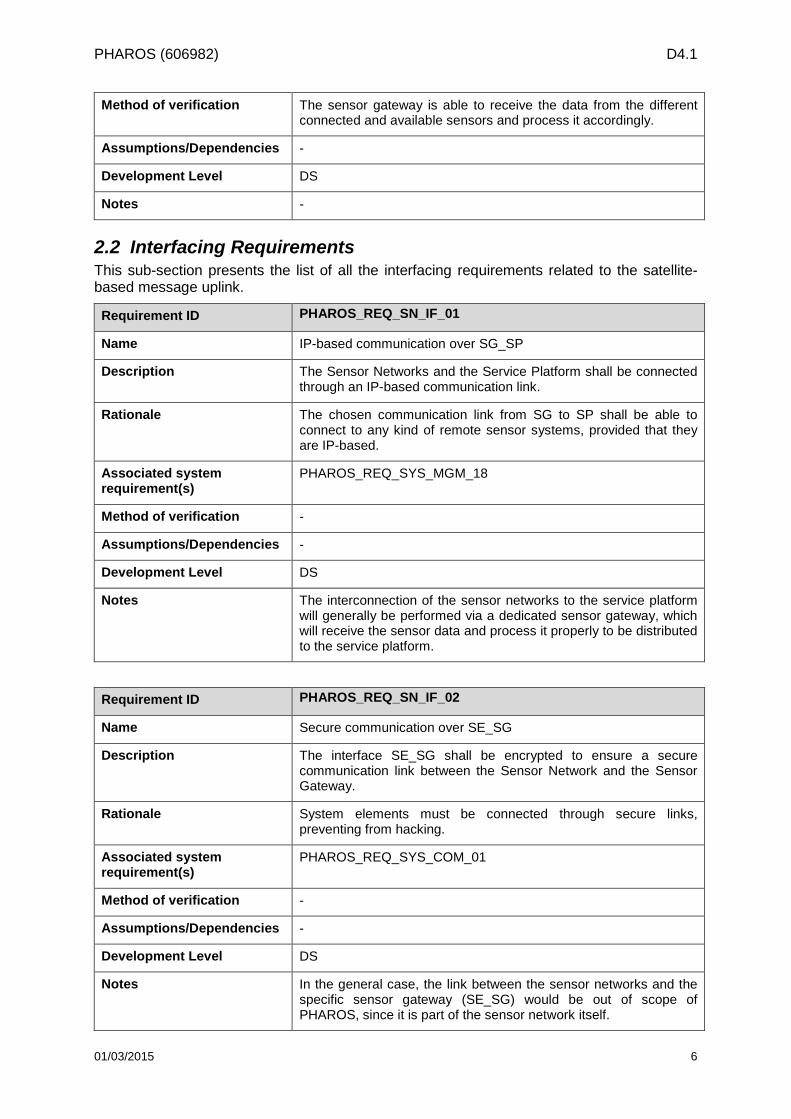
Method of verification The sensor gateway is able to receive the data from the different connected and available sensors and process it accordingly.
Assumptions/Dependencies -
Development Level DS
Notes -
2.2 Interfacing Requirements This sub-section presents the list of all the interfacing requirements related to the satellite-based message uplink.
Requirement ID PHAROS_REQ_SN_IF_01
Name IP-based communication over SG_SP
Description The Sensor Networks and the Service Platform shall be connected through an IP-based communication link.
Rationale The chosen communication link from SG to SP shall be able to connect to any kind of remote sensor systems, provided that they are IP-based.
Associated system requirement(s)
PHAROS_REQ_SYS_MGM_18
Method of verification -
Assumptions/Dependencies -
Development Level DS
Notes The interconnection of the sensor networks to the service platform will generally be performed via a dedicated sensor gateway, which will receive the sensor data and process it properly to be distributed to the service platform.
Requirement ID PHAROS_REQ_SN_IF_02
Name Secure communication over SE_SG
Description The interface SE_SG shall be encrypted to ensure a secure communication link between the Sensor Network and the Sensor Gateway.
Rationale System elements must be connected through secure links, preventing from hacking.
Associated system requirement(s)
PHAROS_REQ_SYS_COM_01
Method of verification -
Assumptions/Dependencies -
Development Level DS
Notes In the general case, the link between the sensor networks and the specific sensor gateway (SE_SG) would be out of scope of PHAROS, since it is part of the sensor network itself.
01/03/2015 6
PHAROS (606982) D4.1
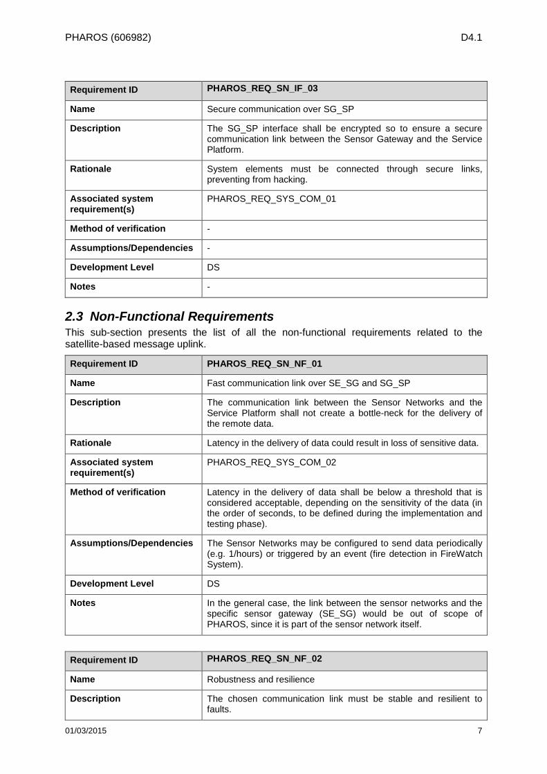
Requirement ID PHAROS_REQ_SN_IF_03
Name Secure communication over SG_SP
Description The SG_SP interface shall be encrypted so to ensure a secure communication link between the Sensor Gateway and the Service Platform.
Rationale System elements must be connected through secure links, preventing from hacking.
Associated system requirement(s)
PHAROS_REQ_SYS_COM_01
Method of verification -
Assumptions/Dependencies -
Development Level DS
Notes -
2.3 Non-Functional Requirements This sub-section presents the list of all the non-functional requirements related to the satellite-based message uplink.
Requirement ID PHAROS_REQ_SN_NF_01
Name Fast communication link over SE_SG and SG_SP
Description The communication link between the Sensor Networks and the Service Platform shall not create a bottle-neck for the delivery of the remote data.
Rationale Latency in the delivery of data could result in loss of sensitive data.
Associated system requirement(s)
PHAROS_REQ_SYS_COM_02
Method of verification Latency in the delivery of data shall be below a threshold that is considered acceptable, depending on the sensitivity of the data (in the order of seconds, to be defined during the implementation and testing phase).
Assumptions/Dependencies The Sensor Networks may be configured to send data periodically (e.g. 1/hours) or triggered by an event (fire detection in FireWatch System).
Development Level DS
Notes In the general case, the link between the sensor networks and the specific sensor gateway (SE_SG) would be out of scope of PHAROS, since it is part of the sensor network itself.
Requirement ID PHAROS_REQ_SN_NF_02
Name Robustness and resilience
Description The chosen communication link must be stable and resilient to faults.
01/03/2015 7
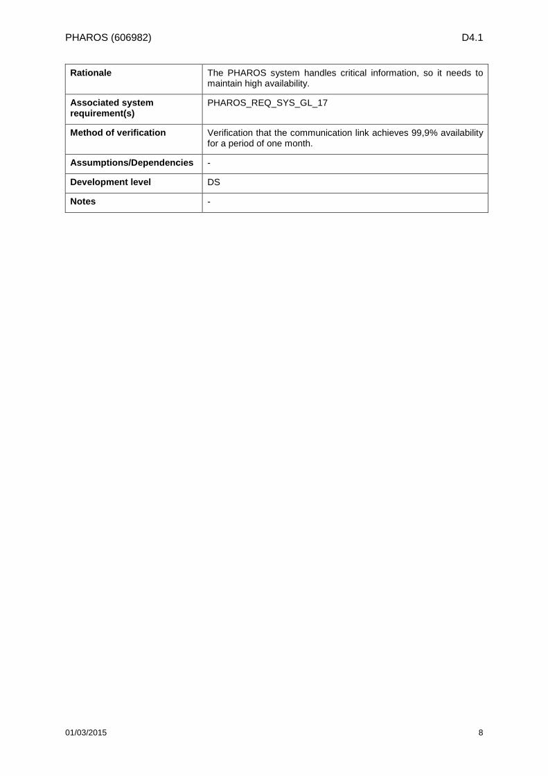
PHAROS (606982) D4.1
Rationale The PHAROS system handles critical information, so it needs to maintain high availability.
Associated system requirement(s)
PHAROS_REQ_SYS_GL_17
Method of verification Verification that the communication link achieves 99,9% availability for a period of one month.
Assumptions/Dependencies -
Development level DS
Notes -
01/03/2015 8
PHAROS (606982) D4.1
3 Reference Scenario This section describes the reference scenario that will be considered for designing and specifying the PHAROS system throughout the duration of the project and beyond (short and long term approaches).
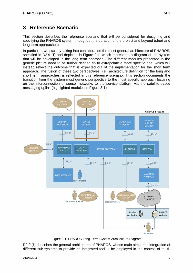
In particular, we start by taking into consideration the most general architecture of PHAROS, specified in D2.9 [1] and depicted in Figure 3-1, which represents a diagram of the system that will be developed in the long term approach. The different modules presented in the generic picture need to be further defined so to extrapolate a more specific one, which will instead reflect the outcome that is expected out of the implementation for the short term approach. The fusion of these two perspectives, i.e., architecture definition for the long and short term approaches, is reflected in this reference scenario. This section documents the transition from the system most generic perspective to the most specific approach focusing on the interconnection of sensor networks to the service platform via the satellite-based messaging uplink (highlighted modules in Figure 3-1).
ALERTINGCHANNELS
SERVICE PLATFORMWORKFLOW ENGINE GATEWAY
EO DATA PROCESSOR
SENSOR GATEWAY
SIMULATION SERVICES
DECISION SUPPORT SERVICES
ALERTING GATEWAYUSER INTERFACE
EO_SP SG_SP SS_SP DS_SP
UI_SPSU_SP AG_SP
PRIMARY USERS
EO SERVICE PROVIDER
SENSOR NETWORK
EXTERNALSERVICES
SECONDARY USER SERVICES
AG_AC
DA_EO SE_SG
EX_SP
SECONDARY USERS
PHAROS SYSTEM
DATA REPOSITORY GIS ENGINE
RECIPIENTS
PHAROS Web site
Receiver Application
EXTERNAL EM SYSTEMS
OTHER AUTHORITIES
ES_SP RC_SP
Figure 3-1: PHAROS Long Term System Architecture Diagram
D2.9 [1] describes the general architecture of PHAROS, whose main aim is the integration of different sub-systems to provide an integrated tool to be employed in the context of multi-
01/03/2015 9
PHAROS (606982) D4.1
hazard disaster and risk management. In this context, in-situ networks are intended to acquire data to be used for risk and emergency monitoring and management. In the short term approach, taking into account the expertise of the Consortium and the characteristics of the selected scenario to be used for the implementation and the pilot demonstration phases, the data is transmitted via a satellite link, while alternative communication systems, as the terrestrial ones, can be considered for the long term approach. The advantage of offering a wide variety of communication channels resides in the resultant possible effectiveness improvement that can be achieved.
In order to select a solution that is suitable to be implemented in the system, a set of solutions has been considered and evaluated. In particular, Section 0 provides an overview of Sensor Network solutions which could increase the added value of the overall system, while Section 3.2 presents different communication solutions, both satellite and terrestrial, which could be used to interconnect the available in-situ sensor networks to the service platform.
In the most general case, sensor gateways are entities that lay between the Sensor Network and the Service Platform (SP). They gather the data received from the sensors and process it prior to sending it forward, so to make it readable at the SP. Given the wide variety of data typology that could be gathered from the different sensor networks to be potentially plugged to the system, the gateway is very specific to the selected sensors that are being considered.
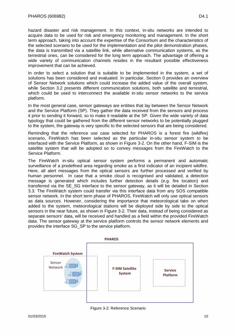
Reminding that the reference use case selected for PHAROS is a forest fire (wildfire) scenario, FireWatch has been selected as the particular in-situ sensor system to be interfaced with the Service Platform, as shown in Figure 3-2. On the other hand, F-SIM is the satellite system that will be adopted so to convey messages from the FireWatch to the Service Platform.
The FireWatch in-situ optical sensor system performs a permanent and automatic surveillance of a predefined area regarding smoke as a first indicator of an incipient wildfire. Here, all alert messages from the optical sensors are further processed and verified by human personnel. In case that a smoke cloud is recognised and validated, a detection message is generated which includes further detection details (e.g. fire location) and transferred via the SE_SG interface to the sensor gateway, as it will be detailed in Section 3.3. The FireWatch system could transfer via this interface data from any SOS compatible sensor network. In the short term phase of PHAROS, FireWatch will only use optical sensors as data sources. However, considering the importance that meteorological take on when added to the system, meteorological stations will be deployed side by side to the optical sensors in the near future, as shown in Figure 3-2. Their data, instead of being considered as separate sensors’ data, will be received and handled as a field within the provided FireWatch data. The sensor gateway at the service platform controls the sensor network elements and provides the interface SG_SP to the service platform.
PHAROS
F-SIM Satellite SystemC
C
CSensor Network
Service Platform
FireWatch System
M
M
M
Figure 3-2: Reference Scenario
01/03/2015 10
PHAROS (606982) D4.1
In the following sub-sections, the different elements that build up the reference scenario will be described. The two first sub-sections present the elements from a general perspective (sensor networks and communication solutions) while the third and fourth sub-sections provide an overview of the particular sensor network to be integrated in PHAROS in the short term approach (FireWatch) and the selected satellite uplink solution to communicate the sensor network with the service platform.
3.1 Sensor Networks Solutions This section provides an overview about the operation and integration of different sensor networks.
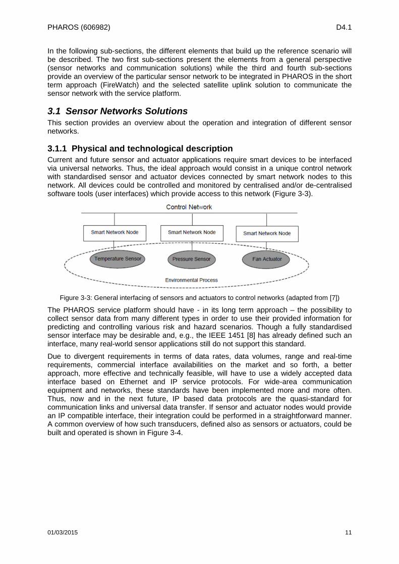
3.1.1 Physical and technological description Current and future sensor and actuator applications require smart devices to be interfaced via universal networks. Thus, the ideal approach would consist in a unique control network with standardised sensor and actuator devices connected by smart network nodes to this network. All devices could be controlled and monitored by centralised and/or de-centralised software tools (user interfaces) which provide access to this network (Figure 3-3).
Figure 3-3: General interfacing of sensors and actuators to control networks (adapted from [7])
The PHAROS service platform should have - in its long term approach – the possibility to collect sensor data from many different types in order to use their provided information for predicting and controlling various risk and hazard scenarios. Though a fully standardised sensor interface may be desirable and, e.g., the IEEE 1451 [8] has already defined such an interface, many real-world sensor applications still do not support this standard.
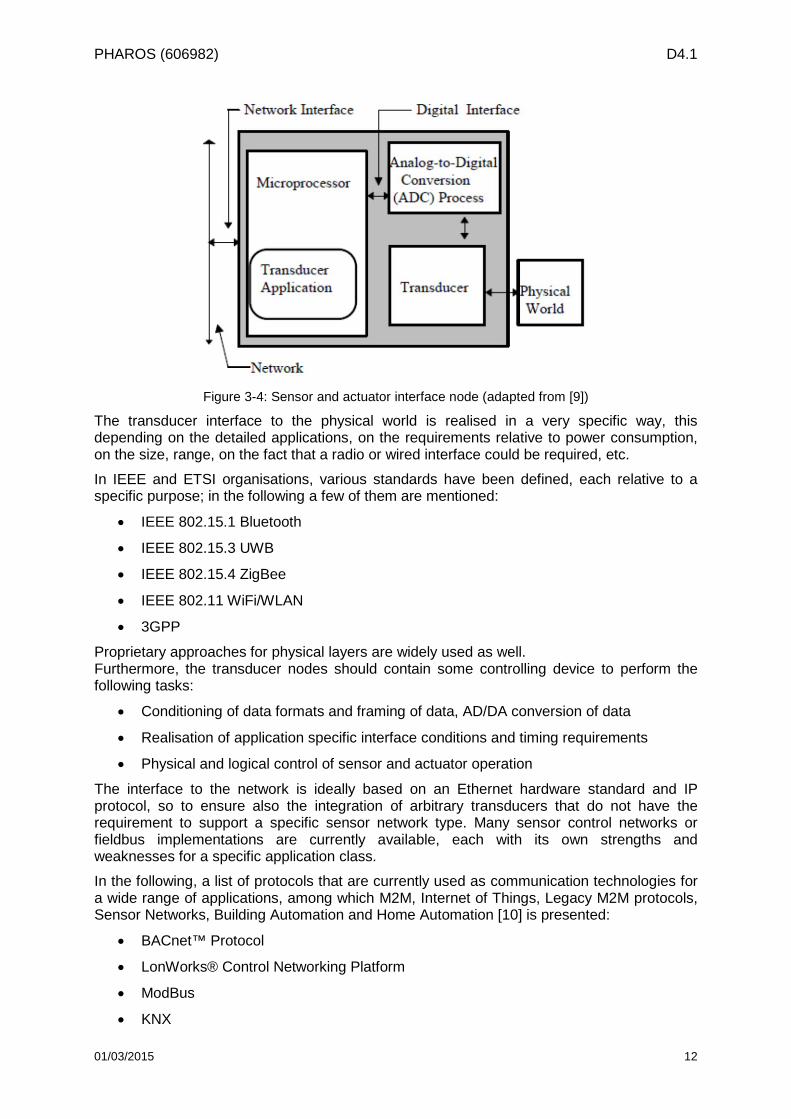
Due to divergent requirements in terms of data rates, data volumes, range and real-time requirements, commercial interface availabilities on the market and so forth, a better approach, more effective and technically feasible, will have to use a widely accepted data interface based on Ethernet and IP service protocols. For wide-area communication equipment and networks, these standards have been implemented more and more often. Thus, now and in the next future, IP based data protocols are the quasi-standard for communication links and universal data transfer. If sensor and actuator nodes would provide an IP compatible interface, their integration could be performed in a straightforward manner. A common overview of how such transducers, defined also as sensors or actuators, could be built and operated is shown in Figure 3-4.
01/03/2015 11
PHAROS (606982) D4.1
Figure 3-4: Sensor and actuator interface node (adapted from [9])
The transducer interface to the physical world is realised in a very specific way, this depending on the detailed applications, on the requirements relative to power consumption, on the size, range, on the fact that a radio or wired interface could be required, etc.
In IEEE and ETSI organisations, various standards have been defined, each relative to a specific purpose; in the following a few of them are mentioned:
• IEEE 802.15.1 Bluetooth
• IEEE 802.15.3 UWB
• IEEE 802.15.4 ZigBee
• IEEE 802.11 WiFi/WLAN
• 3GPP
Proprietary approaches for physical layers are widely used as well. Furthermore, the transducer nodes should contain some controlling device to perform the following tasks:
• Conditioning of data formats and framing of data, AD/DA conversion of data
• Realisation of application specific interface conditions and timing requirements
• Physical and logical control of sensor and actuator operation
The interface to the network is ideally based on an Ethernet hardware standard and IP protocol, so to ensure also the integration of arbitrary transducers that do not have the requirement to support a specific sensor network type. Many sensor control networks or fieldbus implementations are currently available, each with its own strengths and weaknesses for a specific application class.
In the following, a list of protocols that are currently used as communication technologies for a wide range of applications, among which M2M, Internet of Things, Legacy M2M protocols, Sensor Networks, Building Automation and Home Automation [10] is presented:
• BACnet™ Protocol
• LonWorks® Control Networking Platform
• ModBus
• KNX
01/03/2015 12
PHAROS (606982) D4.1
• ZigBee
• Z-Wave
IP-based protocols:
• 6LoWPAN and RPL
• ZigBee Smart Energy 2.0
• ETSI M2M
Interfacing the smart transducers to all these different control networks and supporting the wide variety of protocols, besides requiring a significant effort, is also costly to transducer manufacturers or the PHAROS provider. However by using Ethernet and IP protocol network interfaces, a converter to this standard could be provided by each transducer device. Via TCP/IP gateways, a world-wide data access and transfer scheme is available.
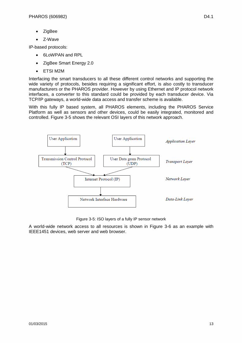
With this fully IP based system, all PHAROS elements, including the PHAROS Service Platform as well as sensors and other devices, could be easily integrated, monitored and controlled. Figure 3-5 shows the relevant OSI layers of this network approach.
Figure 3-5: ISO layers of a fully IP sensor network
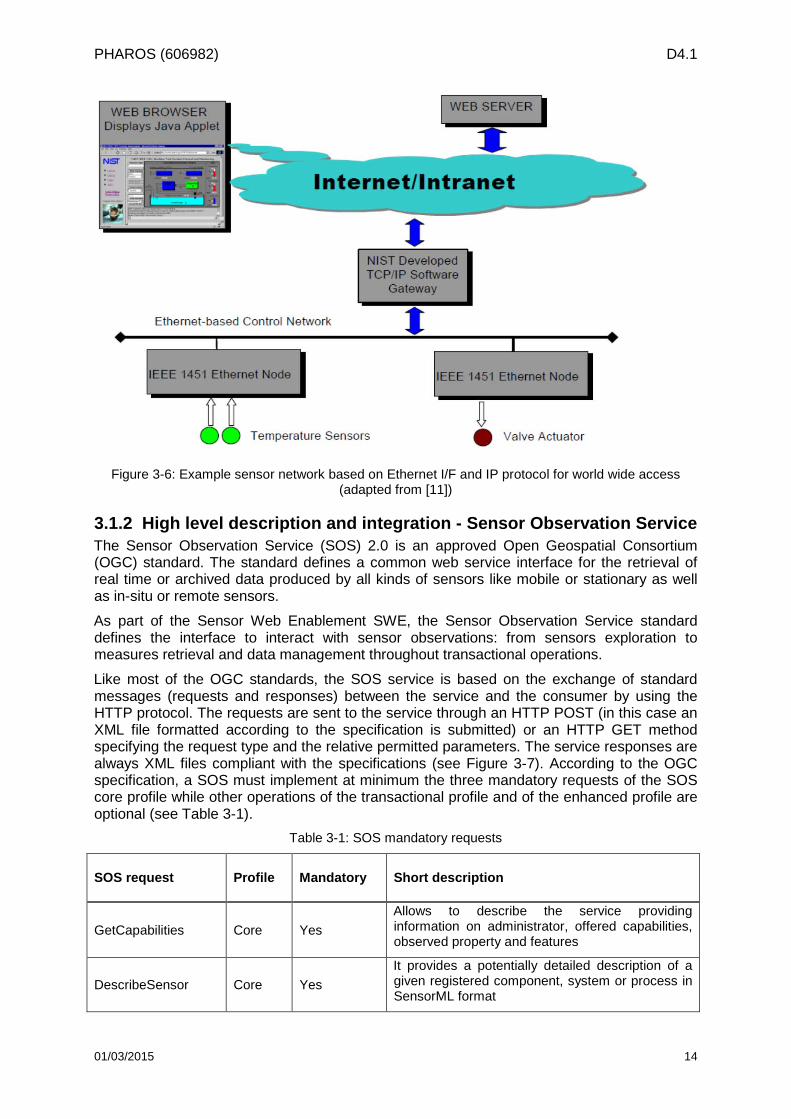
A world-wide network access to all resources is shown in Figure 3-6 as an example with IEEE1451 devices, web server and web browser.
01/03/2015 13
PHAROS (606982) D4.1
Figure 3-6: Example sensor network based on Ethernet I/F and IP protocol for world wide access (adapted from [11])
3.1.2 High level description and integration - Sensor Observation Service The Sensor Observation Service (SOS) 2.0 is an approved Open Geospatial Consortium (OGC) standard. The standard defines a common web service interface for the retrieval of real time or archived data produced by all kinds of sensors like mobile or stationary as well as in-situ or remote sensors.
As part of the Sensor Web Enablement SWE, the Sensor Observation Service standard defines the interface to interact with sensor observations: from sensors exploration to measures retrieval and data management throughout transactional operations.
Like most of the OGC standards, the SOS service is based on the exchange of standard messages (requests and responses) between the service and the consumer by using the HTTP protocol. The requests are sent to the service through an HTTP POST (in this case an XML file formatted according to the specification is submitted) or an HTTP GET method specifying the request type and the relative permitted parameters. The service responses are always XML files compliant with the specifications (see Figure 3-7). According to the OGC specification, a SOS must implement at minimum the three mandatory requests of the SOS core profile while other operations of the transactional profile and of the enhanced profile are optional (see Table 3-1).
Table 3-1: SOS mandatory requests
SOS request Profile Mandatory Short description
GetCapabilities Core Yes Allows to describe the service providing information on administrator, offered capabilities, observed property and features
DescribeSensor Core Yes It provides a potentially detailed description of a given registered component, system or process in SensorML format
01/03/2015 14
PHAROS (606982) D4.1
GetObservation Core Yes
It provides observations based on the setting of filters that includes timing, processes, phenomena, feature of interest, and other parameters in O&M model
RegisterSensor Transactional No
It provides capability to automatically register a new sensor to the existing service
InsertObservation Transactional No
It provides capability to dynamically insert new observation(s) related to a registered sensor
Figure 3-7: SOS GetObservation Example
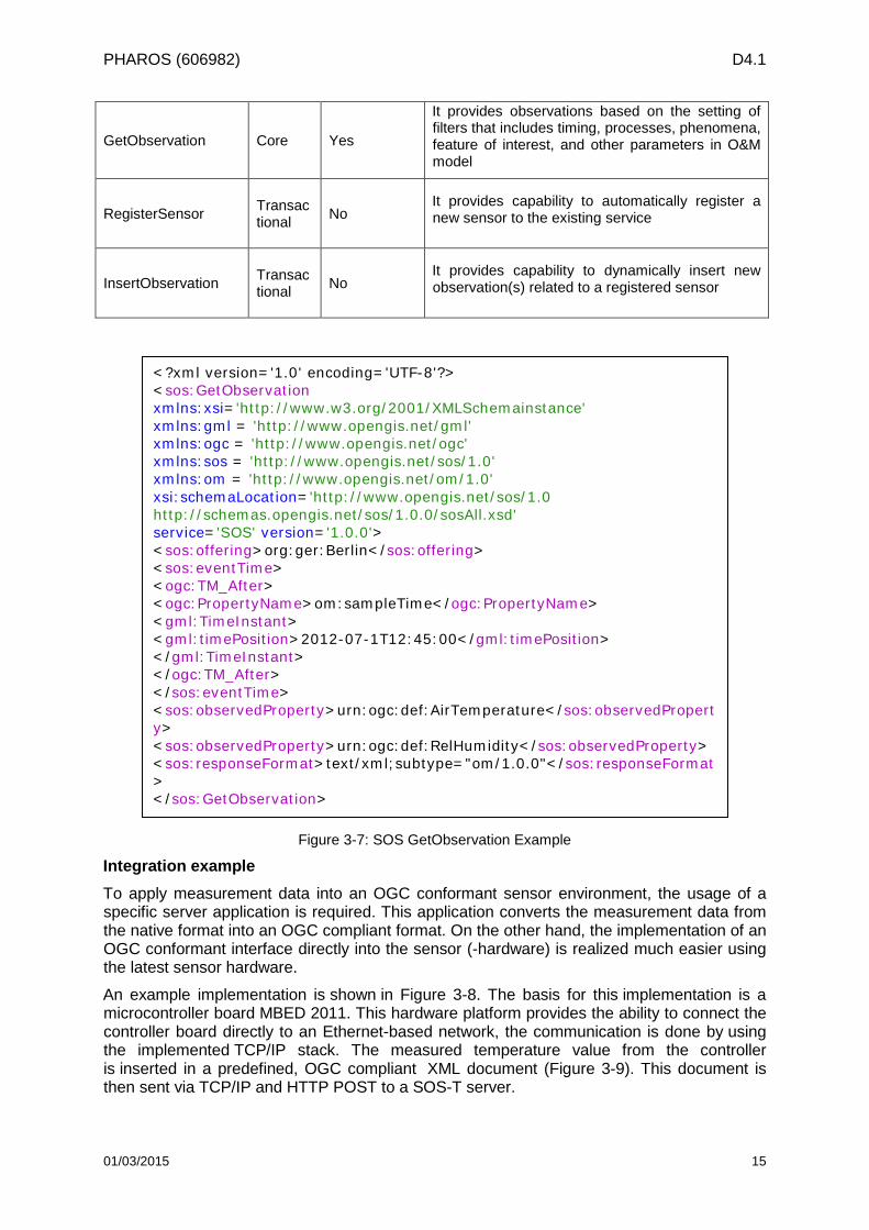
Integration example To apply measurement data into an OGC conformant sensor environment, the usage of a specific server application is required. This application converts the measurement data from the native format into an OGC compliant format. On the other hand, the implementation of an OGC conformant interface directly into the sensor (-hardware) is realized much easier using the latest sensor hardware.
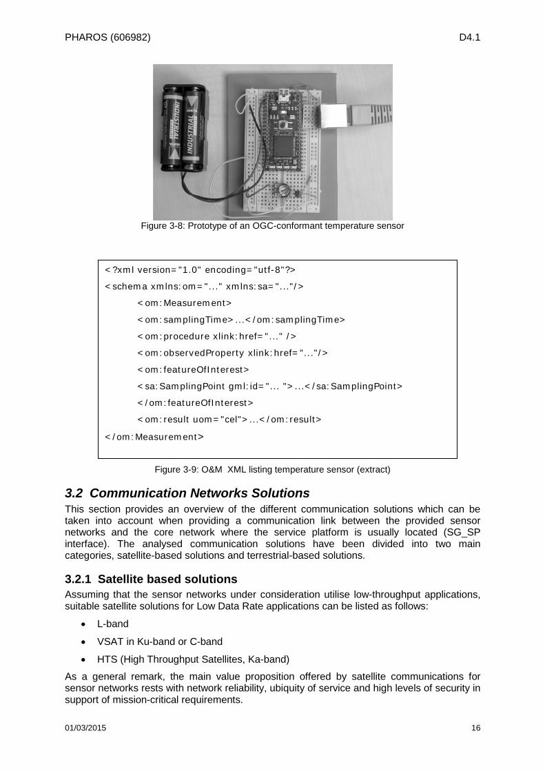
An example implementation is shown in Figure 3-8. The basis for this implementation is a microcontroller board MBED 2011. This hardware platform provides the ability to connect the controller board directly to an Ethernet-based network, the communication is done by using the implemented TCP/IP stack. The measured temperature value from the controller is inserted in a predefined, OGC compliant XML document (Figure 3-9). This document is then sent via TCP/IP and HTTP POST to a SOS-T server.
<?xml version='1.0' encoding='UTF-8'?> <sos:GetObservation xmlns:xsi='http://www.w3.org/2001/XMLSchemainstance' xmlns:gml = 'http://www.opengis.net/gml' xmlns:ogc = 'http://www.opengis.net/ogc' xmlns:sos = 'http://www.opengis.net/sos/1.0' xmlns:om = 'http://www.opengis.net/om/1.0' xsi:schemaLocation='http://www.opengis.net/sos/1.0 http://schemas.opengis.net/sos/1.0.0/sosAll.xsd' service='SOS' version='1.0.0'> <sos:offering>org:ger:Berlin</sos:offering> <sos:eventTime> <ogc:TM_After> <ogc:PropertyName>om:sampleTime</ogc:PropertyName> <gml:TimeInstant> <gml:timePosition>2012-07-1T12:45:00</gml:timePosition> </gml:TimeInstant> </ogc:TM_After> </sos:eventTime> <sos:observedProperty>urn:ogc:def:AirTemperature</sos:observedProperty> <sos:observedProperty>urn:ogc:def:RelHumidity</sos:observedProperty> <sos:responseFormat>text/xml;subtype="om/1.0.0"</sos:responseFormat> </sos:GetObservation>
01/03/2015 15
PHAROS (606982) D4.1
Figure 3-8: Prototype of an OGC-conformant temperature sensor
Figure 3-9: O&M XML listing temperature sensor (extract)
3.2 Communication Networks Solutions This section provides an overview of the different communication solutions which can be taken into account when providing a communication link between the provided sensor networks and the core network where the service platform is usually located (SG_SP interface). The analysed communication solutions have been divided into two main categories, satellite-based solutions and terrestrial-based solutions.
3.2.1 Satellite based solutions Assuming that the sensor networks under consideration utilise low-throughput applications, suitable satellite solutions for Low Data Rate applications can be listed as follows:
• L-band
• VSAT in Ku-band or C-band
• HTS (High Throughput Satellites, Ka-band)
As a general remark, the main value proposition offered by satellite communications for sensor networks rests with network reliability, ubiquity of service and high levels of security in support of mission-critical requirements.
<?xml version="1.0" encoding="utf-8"?>
<schema xmlns:om="..." xmlns:sa="..."/>
<om:Measurement>
<om:samplingTime>...</om:samplingTime>
<om:procedure xlink:href="..." />
<om:observedProperty xlink:href="..."/>
<om:featureOfInterest>
<sa:SamplingPoint gml:id="... ">...</sa:SamplingPoint>
</om:featureOfInterest>
<om:result uom="cel">...</om:result>
</om:Measurement>
01/03/2015 16
PHAROS (606982) D4.1
Whenever there is a requirement for collecting data from remote “white” areas where no type of communication is provided for lack of terrestrial infrastructures (no base stations for GSM/UMTS coverage, no cables for wired connection), the satellite represents the unique solution to provide connectivity.
Additionally, when dealing with hazardous events, it may happen that a terrestrial infrastructure was initially available and used to connect the remote sensors, but suddenly it becomes not available as a consequence of the event itself. For very sensible communications, the satellite is used as a secondary link, in order to back-up (whole or part of) the functionalities of the terrestrial primary link when it is not operating.
On the other hand, the satellite communication may introduce further latency in the link that could have impact on applications where real-time is important. This latency is due to the physical distance run by the data starting from the remote sensor networks to the satellite in orbit (from 100 Km for low orbits and 36.000 Km for geostationary orbits) and back to the satellite hub, and cannot be compressed. However, when considering that in the case of geostationary satellites this path takes ~250milliseconds, then it is an acceptable balance with the benefits of an omni-present link.
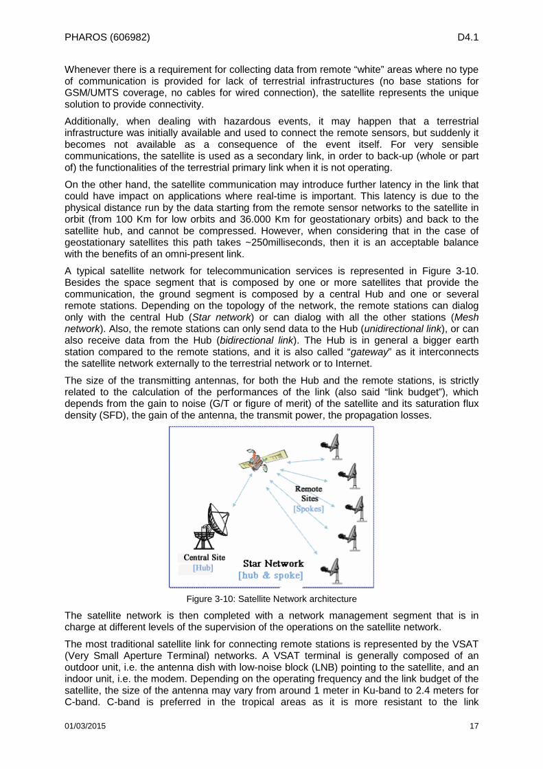
A typical satellite network for telecommunication services is represented in Figure 3-10. Besides the space segment that is composed by one or more satellites that provide the communication, the ground segment is composed by a central Hub and one or several remote stations. Depending on the topology of the network, the remote stations can dialog only with the central Hub (Star network) or can dialog with all the other stations (Mesh network). Also, the remote stations can only send data to the Hub (unidirectional link), or can also receive data from the Hub (bidirectional link). The Hub is in general a bigger earth station compared to the remote stations, and it is also called “gateway” as it interconnects the satellite network externally to the terrestrial network or to Internet.
The size of the transmitting antennas, for both the Hub and the remote stations, is strictly related to the calculation of the performances of the link (also said “link budget”), which depends from the gain to noise (G/T or figure of merit) of the satellite and its saturation flux density (SFD), the gain of the antenna, the transmit power, the propagation losses.
Figure 3-10: Satellite Network architecture
The satellite network is then completed with a network management segment that is in charge at different levels of the supervision of the operations on the satellite network.
The most traditional satellite link for connecting remote stations is represented by the VSAT (Very Small Aperture Terminal) networks. A VSAT terminal is generally composed of an outdoor unit, i.e. the antenna dish with low-noise block (LNB) pointing to the satellite, and an indoor unit, i.e. the modem. Depending on the operating frequency and the link budget of the satellite, the size of the antenna may vary from around 1 meter in Ku-band to 2.4 meters for C-band. C-band is preferred in the tropical areas as it is more resistant to the link
01/03/2015 17
PHAROS (606982) D4.1
degradation caused by the rain and other atmospheric agents. Typical VSAT terminals provide data-rates of 5 Mbps in reception and 2 Mbps in transmission. The cost of the equipment is in the order of 2-3 K€ per unit. VSAT are used for example for remote monitoring of Oil & Gas pipelines and SCADA (Supervisory Control and Data Acquisition) applications, where only 1 terminal is installed to relay many of these remote sensors. However, the operational costs of the VSAT make them valuable for bigger volume of traffic in the order of Mbytes or even GBytes per month, i.e. for backhauling of data from the remote sites. As any other satellite network system, the VSATs are connected to an Earth Station with a Hub operating the received signals, that could be installed directly at the headquarters of the network, or in a different location, as a teleport and then connected to the external service headquarters.
Other satellite solutions that are suitable for connecting remote sensors are based on MSS (Mobile Satellite Services) at lower frequencies, typically in L-band or S-band. These services are operated by geostationary (GEO) and non-geostationary satellites. In the case of non-geostationary satellites, a constellation of several satellites orbiting around the Earth in low- (LEO) or medium-orbit (MEO) ensure a continuous coverage on the deserved regions. Examples of MSS in L-band are the voice communication services (satellite phones) by INMARSAT (GEO), IRIDIUM (LEO), GLOBALSTAR (LEO), Thuraya (GEO). Available bandwidth in these frequency bands is lower than in the higher frequencies. Most of the services providers have specific offers for machine-to-machine applications, where a very low data-rate is required from time to time, and for the called ‘store and forward’ terminals. These mobile solutions are also suitable for applications on-board of vehicles or vessels on the sea. Another advantage compared to the VSAT solution is that the equipment for MSS is smaller in size, with compact form-factors. An interesting case in this category is represented by Orbcomm, which with its constellation of around 30 satellites in low orbit (LEO) provides machine-to-machine services in VHF frequency.
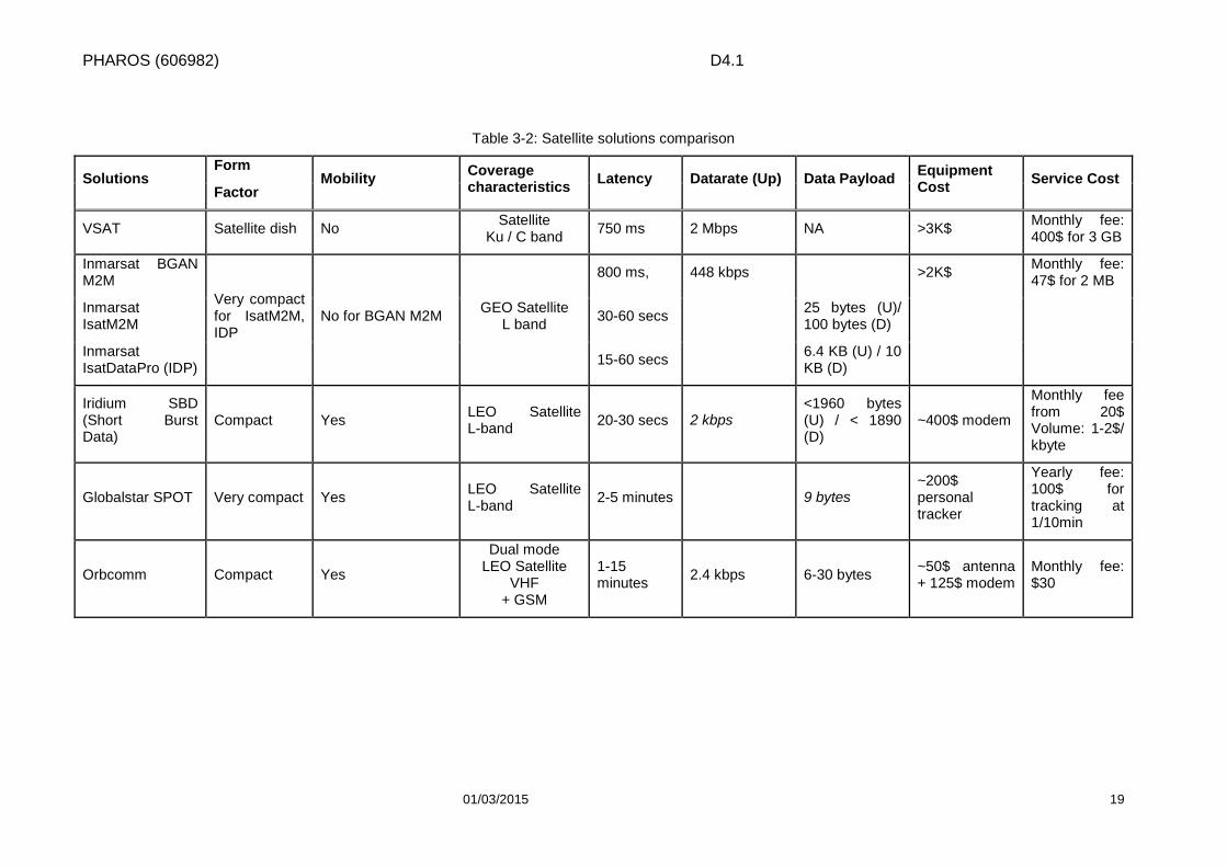
The Table 3-2 summarises the main characteristics for the satellite solutions for M2M.
In the last decade, the new generation of High-Throughput Satellites (HTS) in Ka-band have introduced broadband bidirectional networks and services via satellite, ensuring high-performances comparable to terrestrial ADSL with competitive costs. HTS satellites have multi-beam coverages with average a hundred of spots of 500 Km-diameter. A colour scheme model allows the frequency reuse over the spots, thus multiplying the total capacity in terms of bandwidth of the system. In comparison to the traditional satellites with large beam coverages, the costs of these new HTS satellites remain in the same row order of magnitude (construction, launch), while the throughput offered by the HTS is in the order of x10s, therefore the cost/Gbps is reduced and the provided services are cost-effective.
01/03/2015 18
PHAROS (606982) D4.1
Table 3-2: Satellite solutions comparison
Solutions Form
Mobility Coverage characteristics Latency Datarate (Up) Data Payload Equipment
Cost Service Cost Factor
VSAT Satellite dish No Satellite Ku / C band 750 ms 2 Mbps NA >3K$ Monthly fee:
400$ for 3 GB
Inmarsat BGAN M2M
Very compact for IsatM2M, IDP
No for BGAN M2M GEO Satellite L band
800 ms, 448 kbps >2K$ Monthly fee: 47$ for 2 MB
Inmarsat IsatM2M 30-60 secs 25 bytes (U)/
100 bytes (D)
Inmarsat IsatDataPro (IDP) 15-60 secs 6.4 KB (U) / 10
KB (D)
Iridium SBD (Short Burst Data)
Compact Yes LEO Satellite L-band 20-30 secs 2 kbps
<1960 bytes (U) / < 1890 (D)
~400$ modem
Monthly fee from 20$ Volume: 1-2$/ kbyte
Globalstar SPOT Very compact Yes LEO Satellite L-band 2-5 minutes 9 bytes
~200$ personal tracker
Yearly fee: 100$ for tracking at 1/10min
Orbcomm Compact Yes
Dual mode LEO Satellite
VHF + GSM
1-15 minutes 2.4 kbps 6-30 bytes ~50$ antenna
+ 125$ modem Monthly fee: $30
01/03/2015 19
PHAROS (606982) D4.1
3.2.2 Terrestrial based solutions As it has been already pointed out in the previous section, in general terms a satellite link can be seen both as a complement and a back up to terrestrial solutions. Given the natural resilience of satellite systems to earthly disastrous events, to consider it as such is especially relevant in those cases when terrestrial connections could easily become unavailable, compromising thus point to point communications. However, terrestrial connections represent not only faster but also ubiquitous solutions, allowing a seamless connection in pre-disaster phases. Therefore it is relevant that the most widespread terrestrial based solutions (GSM, GPRS, EDGE, UMTS, LTE, WiMAX, DSL) should be listed among alternative solutions to the satellite link. Apart from DSL, which provides internet access over a telephone line, the technologies that have been taken into consideration provide wireless voice and internet connection. A short introduction to these terrestrial based solutions is provided in the following.
Widely acknowledge among the major mobile phone standards, GSM comprises a set of protocols of second generation for digital networks. It offers circuit-switching services with the highest achievable data rate of 9.6 kbps, operating at 900 MHz and 1800 MHz and TDMA signalling over FDD carriers. Originally designed for voice communication, it has been developed in several phases by ETSI, aiming at offering higher data rates (High Speed Circuit-Switched Data service) and internet access via GPRS Core Network. GPRS is a packet oriented service that has been developed to support packet switching services in GSM by adding new network elements. It offers a higher data rate than GSM, up to a nominal 160 kbit/s. Another extension to GSM/GPRS, based on GSM physical layer, is EDGE, which allows for more communication capabilities, reaching 384 kbit/s. GPRS and EDGE are considered 2.5G technology, such as transitions from 2G to 3G.
UMTS is a 3G standard based on evolved GSM core network and WCDMA radio technology, which offers greater spectral efficiency and higher bandwidth than 2G and 2.5G technology, due to different data coding and spectral bandwidth usage. UTRAN has been the first radio scheme implemented in UMTS, however HSPA has been later developed to offer high speed uplink packet access (HSUPA) and high speed downlink packet access (HSDPA), both potentially offering 10Mbit/s.
LTE has been appointed by 3GPP as the global standard for the fourth generation of broadband mobile networks; it is based on UMTS and makes it evolve towards a packet only system. Compared to 3G wireless networks, LTE is a low cost system, as it deploys a smaller number of network elements and in general a simplified architecture with respect to its predecessors, providing thus higher performance in terms of latency, data rates and backwards compatibility with other communication systems. LTE offers high speed connection, reached through HSDPA (peak of 300Mbit/s) and HSUPA (peak of 75Mbit/s). A variety of channels are used, from 1.4 MHz to 20 MHz, with 100 MHz max aggregated bandwidth by aggregating up to 5 component carriers (LTE release 10).
WiMAX is a 4G candidate system; it is based on the interoperable implementation of IEEE 802.16 standards, ratified by the WiMAX forum. It enables the delivery of broadband services and can accommodate fixed and mobile usage models across a range of applications. The IEEE 802.16 standard was developed to deliver non-line-of-sight connectivity between a subscriber station and base station. Like LTE, WiMAX is IP based, supports advanced MIMO, and use modulation technology based on OFMD. Both support mobility of the terminal. With respect to LTE, WiMAX is cheaper to deploy, but misses the 3G compatibility.
DSL is a family of technology used to provide cabled internet access. Data rate varies considerably from few hundreds kbps to over 100Mbit/s, depending on the specific DSL 01/03/2015 20
PHAROS (606982) D4.1
technology. The equipment is constituted by a router and a modem, which can be connected to the user both via LAN and WLAN.
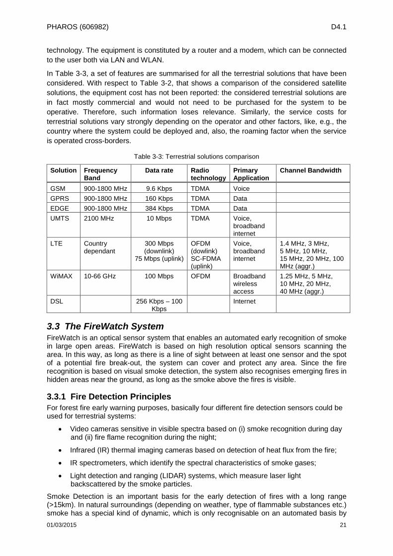
In Table 3-3, a set of features are summarised for all the terrestrial solutions that have been considered. With respect to Table 3-2, that shows a comparison of the considered satellite solutions, the equipment cost has not been reported: the considered terrestrial solutions are in fact mostly commercial and would not need to be purchased for the system to be operative. Therefore, such information loses relevance. Similarly, the service costs for terrestrial solutions vary strongly depending on the operator and other factors, like, e.g., the country where the system could be deployed and, also, the roaming factor when the service is operated cross-borders.
Table 3-3: Terrestrial solutions comparison
Solution Frequency Band
Data rate Radio technology
Primary Application
Channel Bandwidth
GSM 900-1800 MHz 9.6 Kbps TDMA Voice GPRS 900-1800 MHz 160 Kbps TDMA Data EDGE 900-1800 MHz 384 Kbps TDMA Data UMTS 2100 MHz 10 Mbps TDMA Voice,
broadband internet
LTE Country dependant
300 Mbps (downlink)
75 Mbps (uplink)
OFDM (dowlink) SC-FDMA (uplink)
Voice, broadband internet
1.4 MHz, 3 MHz, 5 MHz, 10 MHz, 15 MHz, 20 MHz, 100 MHz (aggr.)
WiMAX 10-66 GHz 100 Mbps OFDM Broadband wireless access
1.25 MHz, 5 MHz, 10 MHz, 20 MHz, 40 MHz (aggr.)
DSL 256 Kbps – 100 Kbps
Internet
3.3 The FireWatch System FireWatch is an optical sensor system that enables an automated early recognition of smoke in large open areas. FireWatch is based on high resolution optical sensors scanning the area. In this way, as long as there is a line of sight between at least one sensor and the spot of a potential fire break-out, the system can cover and protect any area. Since the fire recognition is based on visual smoke detection, the system also recognises emerging fires in hidden areas near the ground, as long as the smoke above the fires is visible.
3.3.1 Fire Detection Principles For forest fire early warning purposes, basically four different fire detection sensors could be used for terrestrial systems:
• Video cameras sensitive in visible spectra based on (i) smoke recognition during day and (ii) fire flame recognition during the night;
• Infrared (IR) thermal imaging cameras based on detection of heat flux from the fire;
• IR spectrometers, which identify the spectral characteristics of smoke gases;
• Light detection and ranging (LIDAR) systems, which measure laser light backscattered by the smoke particles.
Smoke Detection is an important basis for the early detection of fires with a long range (>15km). In natural surroundings (depending on weather, type of flammable substances etc.) smoke has a special kind of dynamic, which is only recognisable on an automated basis by 01/03/2015 21
PHAROS (606982) D4.1
means of modern identification technology, computer science and image processing software.
It is common understanding that terrestrial systems based on CCD video cameras sensitive in visible and near IR spectra are today the best and the most effective solutions for realising automatic surveillance and automatic forest fire detection systems. The additional use of the NIR-area guarantees deeper penetration of “hazy” atmospheric conditions with a multiplier factor of 1.4-1.6. In almost every country that encounters high risk of forest fires, at least one of such systems has been proposed and developed. In all these systems, automatic forest fire detection is based on smoke recognition during the day and flame recognition during the night.
3.3.2 System Overview and Performance of FireWatch As anticipated, the forest fire early warning system FireWatch is based on a smoke detection technology. The basic patent pending technology for the smoke detection algorithm as well as the camera design have been developed by the German Aerospace Centre DLR during the program ROLIS (Rosetta Lander Imaging System), which is the imaging unit of the landing spacecraft onto the comet Churyumov-Gerasimenko. Satellite and lander performed a successful operation in November 2014 and transmitted brilliant pictures back to Earth.
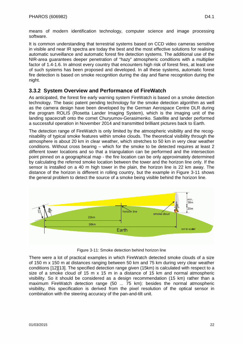
The detection range of FireWatch is only limited by the atmospheric visibility and the recog-nisability of typical smoke features within smoke clouds. The theoretical visibility through the atmosphere is about 20 km in clear weather, which stretches to 50 km in very clear weather conditions. Without cross bearing – which for the smoke to be detected requires at least 2 different tower locations and so that a triangulation can be performed and the intersection point pinned on a geographical map - the fire location can be only approximately determined by calculating the referred smoke location between the tower and the horizon line only. If the sensor is installed on a 40 m high tower in the plain, the horizon line is 22 km away. The distance of the horizon is different in rolling country, but the example in Figure 3-11 shows the general problem to detect the source of a smoke being visible behind the horizon line.
Figure 3-11: Smoke detection behind horizon line
There were a lot of practical examples in which FireWatch detected smoke clouds of a size of 150 m x 150 m at distances ranging between 50 km and 75 km during very clear weather conditions [12][13]. The specified detection range given (15km) is calculated with respect to a size of a smoke cloud of 15 m x 15 m in a distance of 15 km and normal atmospheric visibility. So it should be considered as a design recommendation (15 km) rather than a maximum FireWatch detection range (50 ... 75 km): besides the normal atmospheric visibility, this specification is derived from the pixel resolution of the optical sensor in combination with the steering accuracy of the pan-and-tilt unit.
01/03/2015 22
PHAROS (606982) D4.1
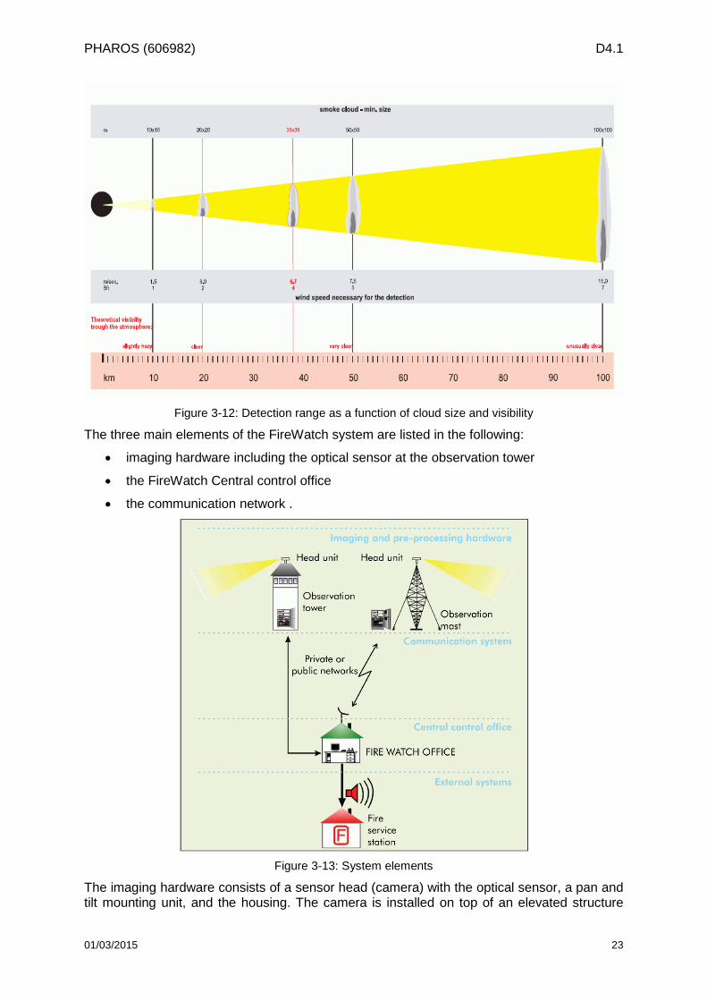
Figure 3-12: Detection range as a function of cloud size and visibility
The three main elements of the FireWatch system are listed in the following:
• imaging hardware including the optical sensor at the observation tower
• the FireWatch Central control office
• the communication network .
Figure 3-13: System elements
The imaging hardware consists of a sensor head (camera) with the optical sensor, a pan and tilt mounting unit, and the housing. The camera is installed on top of an elevated structure
01/03/2015 23
PHAROS (606982) D4.1
such as a tower or a mast. Each unit covers a radius of 10 to 15 km depending on the visibility and the local elevation profile, as previously described.
The optical sensor contains a high resolution CCD (Charged Coupled Device) chip with a resolution of 1360 x 1024 pixels. The extremely high grey scale resolution of 14 bit (gray scale of 16.384) enables the application of special image-processing software.
The CCD sensor is sensitive to light with wavelengths from the near infrared to the visible ranges. An interference rejection filter (band-pass filter) and a low pass filter are installed in front of the sensor to limit the detected wavelength to visible or near infrared light, which allows the FireWatch system to switch to night vision. The lens of the CCD sensor have been developed specifically for the FireWatch system.
A local computer is installed at each tower to control the sensor movements and pre-process the acquired images. During the image pre-processing phase, the algorithm compares the current frame with previous frames and determines if there have been changes. The pre-processing step handles not only the automatic detection of smoke within the observed area, but also the transmission of the corresponding alerts to the central office via e.g. radio links, whenever a smoke cloud is detected.
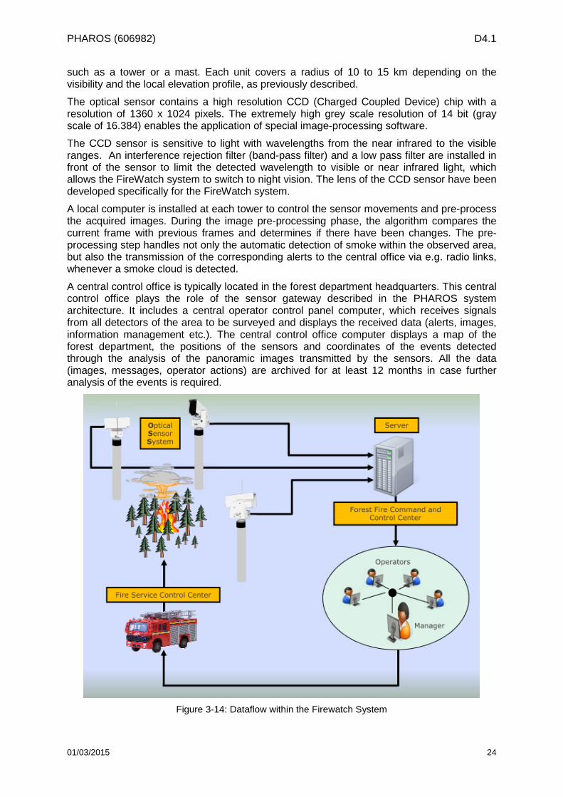
A central control office is typically located in the forest department headquarters. This central control office plays the role of the sensor gateway described in the PHAROS system architecture. It includes a central operator control panel computer, which receives signals from all detectors of the area to be surveyed and displays the received data (alerts, images, information management etc.). The central control office computer displays a map of the forest department, the positions of the sensors and coordinates of the events detected through the analysis of the panoramic images transmitted by the sensors. All the data (images, messages, operator actions) are archived for at least 12 months in case further analysis of the events is required.
Figure 3-14: Dataflow within the Firewatch System
01/03/2015 24
PHAROS (606982) D4.1
Each sensor operates both during the day and the night. A sensor rotates automatically in a circle of 360° capturing images of the area with the number of images taken during one rotation depending mainly on the lens and its opening angle. These images are processed by the tower computer and checked for indications of smoke.
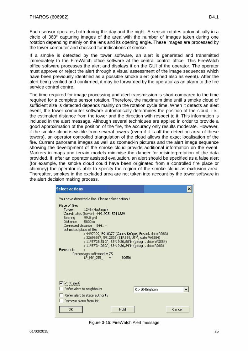
If a smoke is detected by the tower software, an alert is generated and transmitted immediately to the FireWatch office software at the central control office. This FireWatch office software processes the alert and displays it on the GUI of the operator. The operator must approve or reject the alert through a visual assessment of the image sequences which have been previously identified as a possible smoke alert (defined also as event). After the alert being verified and confirmed, it may be forwarded by the operator as an alarm to the fire service control centre.
The time required for image processing and alert transmission is short compared to the time required for a complete sensor rotation. Therefore, the maximum time until a smoke cloud of sufficient size is detected depends mainly on the rotation cycle time. When it detects an alert event, the tower computer software automatically determines the position of the cloud, i.e., the estimated distance from the tower and the direction with respect to it. This information is included in the alert message. Although several techniques are applied in order to provide a good approximation of the position of the fire, the accuracy only results moderate. However, if the smoke cloud is visible from several towers (even if it is off the detection area of these towers), an operator controlled triangulation of the cloud allows the exact localisation of the fire. Current panorama images as well as zoomed-in pictures and the alert image sequence showing the development of the smoke cloud provide additional information on the event. Markers in maps and terrain models minimise the danger for misinterpretation of the data provided. If, after an operator assisted evaluation, an alert should be specified as a false alert (for example, the smoke cloud could have been originated from a controlled fire place or chimney) the operator is able to specify the region of the smoke cloud as exclusion area. Thereafter, smokes in the excluded area are not taken into account by the tower software in the alert decision making process.
Figure 3-15: FireWatch Alert message
01/03/2015 25
PHAROS (606982) D4.1
Typically, during day time operation the system has to make 270 decisions per hour, whether smoke is detected in the recorded images or not. If the detection algorithms discover on the captured images something that could indicate smoke, an alert is sent to the FireWatch office. An event is therefore always an image that includes one or more suspicious points, marked by red rectangles. An event that announced an alert and is not attributed to a fire is interpreted as a false positive alert. Such a false positive alert can be generated by moving automobiles, shadows, airplanes, air turbulences, smog, fog, dust, tree branches, sun reflections and more. An event that looks like a cloud of smoke of a fire, for example smoke from a chimney or rising mist, is not a false positive alert in this sense but a proper decision. The false alert rate is defined as the ratio of number of false alerts to the number of evaluated scenarios. The required testing accuracy should not exceed a rate of 10%. However, this is a statistical value with a wide dispersion, depending on the weather conditions and a proper system parameter adjustment performed by the operator.
The high number of FireWatch systems installed in the last decade and the large scale effective operations in the same period, done with the help of long-term records and extensive research results from the German Forest Department, has played a key role in the continuous technological upgrading, performance gain and high reliability of the FireWatch system. Based on long term statistical data and information from the German Forest Department, the practical achievable rate of false positive alerts of detected fires is less than 3%, while detection reliability remains well above 90% [14].
The FireWatch system distinguishes itself from other similar systems by the following main features and components:
• High geometric resolution of 1360 x 1024 pixels (in contrast to 768 x 576 pixels, TV standard of most competitors)
• Extremely high grey scale resolution of 14 bit (grey scale of 16.384) enables the application of more effective image processing procedures
• Extended spectral sensitivity across a wide range of visible light which goes all the way to near infrared (480 nm to 1200 nm VIS+NIR) achieved by the using a new sensor generation in the FireWatch camera (3rd generation)
• The use of special reversible filters (interference and edge filters) for day/night application ensures a successful accentuation in contrasts, as well as rejection of unwanted light sources (e.g. headlights, street lighting, light from villages or towns against the sky)
The outstanding features of the new camera generation (high signal-to-noise ratio, night vision capacity) were confirmed and certified by DLR.
3.3.3 Role within the PHAROS system Besides providing real time alert messaging, FireWatch also provides other relevant data about the identified wildfires (e.g. geographical location, time of occurrence, images, live sequences), which result useful for the situation assessment performed by the PHAROS operators at the Service Platform, as well as additional information to local rescue personnel.
Within PHAROS, FireWatch provides real-time input data for the Wildfire Analyst Simulator.
All data exchange and all service calls are directed to the Service Platform. The SP works as a central access point (proxy) for all service calls and responses. In order to do so, FireWatch needs a set of core parameters for each service, as specified in D5.3 [15] and reported in the following, as well as in Table 3-4:
• Service ID (a unique identifier per service)
• Assumed consumers, i.e., a non-exhaustive list of the peer modules which are expected to consume the service; this list is informative rather than normative
• Data exchanged (high-level description of the information exchanged) 01/03/2015 26
PHAROS (606982) D4.1
• Operations/Methods supported
• Main parameters (to be included in the service call)
• Data representation protocol (e.g. XML, JSON etc.)
• Communication protocol (mostly HTTP)
• Response (description of expected response) Table 3-4: SP Events and Observations service specification
Service ID SP_EVS
Assumed consumers (via reference point)
Sensor Gateway (SG_SP)
Data exchanged Bundle (e.g. compressed file) containing geodata and camera images
Operations Alarm
Main parameters Timestamp, unique id
Data representation protocol SHP (ESRI shape file), JPEG (Camera Screenshot)
Communication protocol HTTP (POST)
Response ACK
Notes SP is expected to notify the DSS by communicating the event accordingly through the appropriate workflow.
This service specification allows the publication of detected fires and observations derived from processed sensor information. Data from the FireWatch system to be communicated include (as reported in more detail in Table 3-5 and Table 3-6):
• Unique id of detected fires
• Detection timestamp
• Point of origin (e.g. ignition point in case of fire)
• Current perimeter of detected fires
• Images captured by the local camera sensors
The Sensor Gateway uses an HTTP POST operation to upload to the SP a set of several elements describing the event (ID, time, location, ...), the perimeter of the affected area in the format of a shape file and one or more files containing sensor images (e.g. camera captures from the FireWatch detection tower).
01/03/2015 27
PHAROS (606982) D4.1
Table 3-5: SP-SG Sensor Events specification (elements)
Service ID SP_SG_EVS
SP_SG_ALERT
Data of detected fire (Unique ID, timestamp, location of fire, coordinates of sensor, bearing, ...)
SP_SG_IMAGE Image (png, jpg, tiff) with Unique ID of tower, image
SP_SG_STREAM H264 - Stream Unique ID of tower, image (opt.)
SP_SG_PERIM Shapefile (perimeter of affected area)
SP_SG_FIRENAME Allocation of unique name by PHAROS operator
Table 3-6: SG-SP Alert specification
Service ID SP_SG_ALERT
Assumed consumers (via reference point)
User interface, data repository
Data exchanged Fire info
Operations PostFireAlert
Main parameters Unique ID, timestamp, location of fire, coordinates of sensor, bearing, ...
Data representation protocol XML
Communication protocol TCP, HTTP ( POST )
Response OK ( HTTP 201) Error
Notes ---
In the following, an example for fire alert data in XML format which is transmitted from the FireWatch central (sensor gateway) to the SP is reported. <alert localtime=" 14:20:58" date=" 2015-02-05" machine_id="10505" machine_ref="146" alertxml_version="1.1"> <firelocation utmx="14618410" utmy="3367086" south="0" kml="Alert_146_US_FourPts_587.kml"/> <reference ref_name="Jollyville_Fire"/> <alerttype> <suspicion value="false"/> <test value="false"/> <miss value="false"/> </alerttype> <annotations>large fire south of jollyville</annotations> <detections> <detection> <tower name="US_FourPts" number="10506" utmx="14611060" utmy="3362639" z="45"/> <sequence name="10506_20150205_U_141813_1125"/> <ImgId value="1423167658"/> <bearing value="58.7"/> <distance value="8586" unit="m"/> <imagepoint x="347" y="131"/> </detection> <detection>
01/03/2015 28
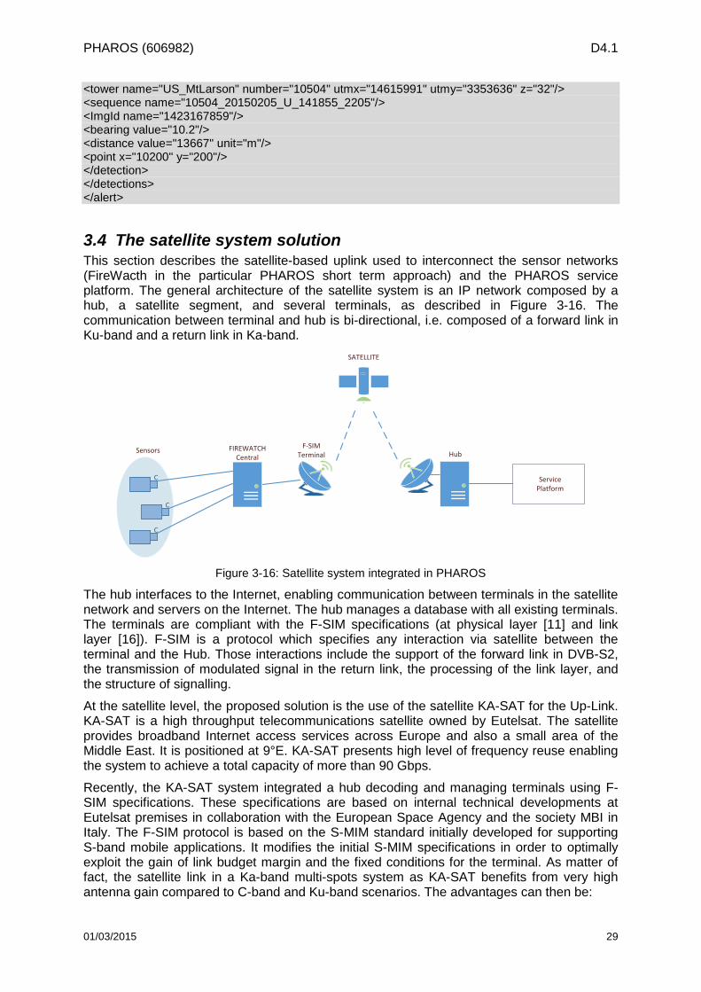
PHAROS (606982) D4.1
<tower name="US_MtLarson" number="10504" utmx="14615991" utmy="3353636" z="32"/> <sequence name="10504_20150205_U_141855_2205"/> <ImgId name="1423167859"/> <bearing value="10.2"/> <distance value="13667" unit="m"/> <point x="10200" y="200"/> </detection> </detections> </alert>
3.4 The satellite system solution This section describes the satellite-based uplink used to interconnect the sensor networks (FireWacth in the particular PHAROS short term approach) and the PHAROS service platform. The general architecture of the satellite system is an IP network composed by a hub, a satellite segment, and several terminals, as described in Figure 3-16. The communication between terminal and hub is bi-directional, i.e. composed of a forward link in Ku-band and a return link in Ka-band.
FIREWATCH Central
SATELLITE
C
C
C
F-SIM Terminal HubSensors
Service Platform
Figure 3-16: Satellite system integrated in PHAROS
The hub interfaces to the Internet, enabling communication between terminals in the satellite network and servers on the Internet. The hub manages a database with all existing terminals. The terminals are compliant with the F-SIM specifications (at physical layer [11] and link layer [16]). F-SIM is a protocol which specifies any interaction via satellite between the terminal and the Hub. Those interactions include the support of the forward link in DVB-S2, the transmission of modulated signal in the return link, the processing of the link layer, and the structure of signalling.
At the satellite level, the proposed solution is the use of the satellite KA-SAT for the Up-Link. KA-SAT is a high throughput telecommunications satellite owned by Eutelsat. The satellite provides broadband Internet access services across Europe and also a small area of the Middle East. It is positioned at 9°E. KA-SAT presents high level of frequency reuse enabling the system to achieve a total capacity of more than 90 Gbps.
Recently, the KA-SAT system integrated a hub decoding and managing terminals using F-SIM specifications. These specifications are based on internal technical developments at Eutelsat premises in collaboration with the European Space Agency and the society MBI in Italy. The F-SIM protocol is based on the S-MIM standard initially developed for supporting S-band mobile applications. It modifies the initial S-MIM specifications in order to optimally exploit the gain of link budget margin and the fixed conditions for the terminal. As matter of fact, the satellite link in a Ka-band multi-spots system as KA-SAT benefits from very high antenna gain compared to C-band and Ku-band scenarios. The advantages can then be:
01/03/2015 29
PHAROS (606982) D4.1
• The use of a reduced power at the antenna input port
• The increase of the user terminal bitrate
The main interest of the F-SIM protocol resides in two important characteristics. On one hand, the protocol presents an excellent trade-off between the occupied bandwidth for the communication and an acceptable user bitrate allowing transmitting data like small video sequences. It is characterised by the possibility to be adapted to the user bitrate and the bandwidth to different service requirements. On the other hand, the advantage is to reach very good performances in terms of spectral efficiency even using a very simplified access scheme. In fact, the system is able to correctly demodulate total loads superior to 2 bits/s/Hz, up to now inconceivable for a system exploiting a totally random and unsynchronised access scheme. The terminals using F-SIM specifications represent a very low-cost effective solution compared to the other ones available today.
This global performance is made possible not only by the characteristics of the protocol but by the exploitation of an innovative power control algorithm too. The latter optimises the power used by each terminal in function of the service requirements. This terminal power control is operating in open loop thus not causing any unwanted signalling overhead.
01/03/2015 30
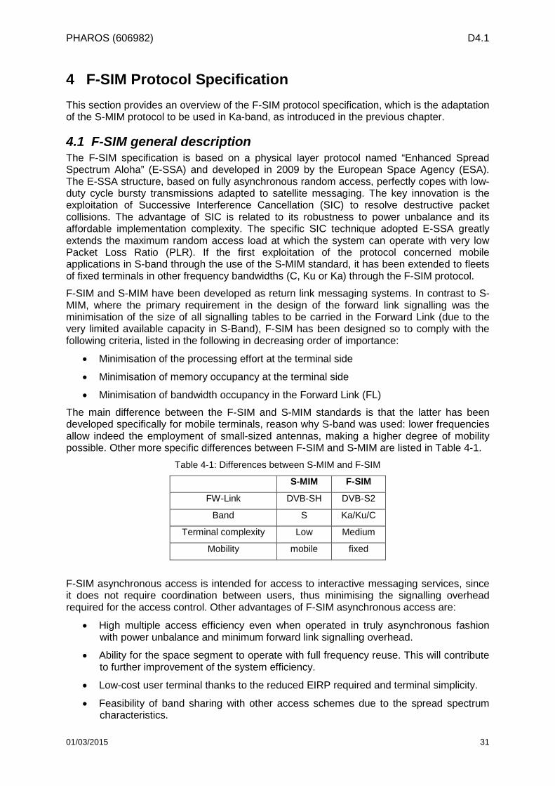
PHAROS (606982) D4.1
4 F-SIM Protocol Specification This section provides an overview of the F-SIM protocol specification, which is the adaptation of the S-MIM protocol to be used in Ka-band, as introduced in the previous chapter.
4.1 F-SIM general description The F-SIM specification is based on a physical layer protocol named “Enhanced Spread Spectrum Aloha” (E-SSA) and developed in 2009 by the European Space Agency (ESA). The E-SSA structure, based on fully asynchronous random access, perfectly copes with low-duty cycle bursty transmissions adapted to satellite messaging. The key innovation is the exploitation of Successive Interference Cancellation (SIC) to resolve destructive packet collisions. The advantage of SIC is related to its robustness to power unbalance and its affordable implementation complexity. The specific SIC technique adopted E-SSA greatly extends the maximum random access load at which the system can operate with very low Packet Loss Ratio (PLR). If the first exploitation of the protocol concerned mobile applications in S-band through the use of the S-MIM standard, it has been extended to fleets of fixed terminals in other frequency bandwidths (C, Ku or Ka) through the F-SIM protocol.
F-SIM and S-MIM have been developed as return link messaging systems. In contrast to S-MIM, where the primary requirement in the design of the forward link signalling was the minimisation of the size of all signalling tables to be carried in the Forward Link (due to the very limited available capacity in S-Band), F-SIM has been designed so to comply with the following criteria, listed in the following in decreasing order of importance:
• Minimisation of the processing effort at the terminal side
• Minimisation of memory occupancy at the terminal side
• Minimisation of bandwidth occupancy in the Forward Link (FL)
The main difference between the F-SIM and S-MIM standards is that the latter has been developed specifically for mobile terminals, reason why S-band was used: lower frequencies allow indeed the employment of small-sized antennas, making a higher degree of mobility possible. Other more specific differences between F-SIM and S-MIM are listed in Table 4-1.
Table 4-1: Differences between S-MIM and F-SIM
S-MIM F-SIM
FW-Link DVB-SH DVB-S2
Band S Ka/Ku/C
Terminal complexity Low Medium
Mobility mobile fixed
F-SIM asynchronous access is intended for access to interactive messaging services, since it does not require coordination between users, thus minimising the signalling overhead required for the access control. Other advantages of F-SIM asynchronous access are:
• High multiple access efficiency even when operated in truly asynchronous fashion with power unbalance and minimum forward link signalling overhead.
• Ability for the space segment to operate with full frequency reuse. This will contribute to further improvement of the system efficiency.
• Low-cost user terminal thanks to the reduced EIRP required and terminal simplicity.
• Feasibility of band sharing with other access schemes due to the spread spectrum characteristics.
01/03/2015 31
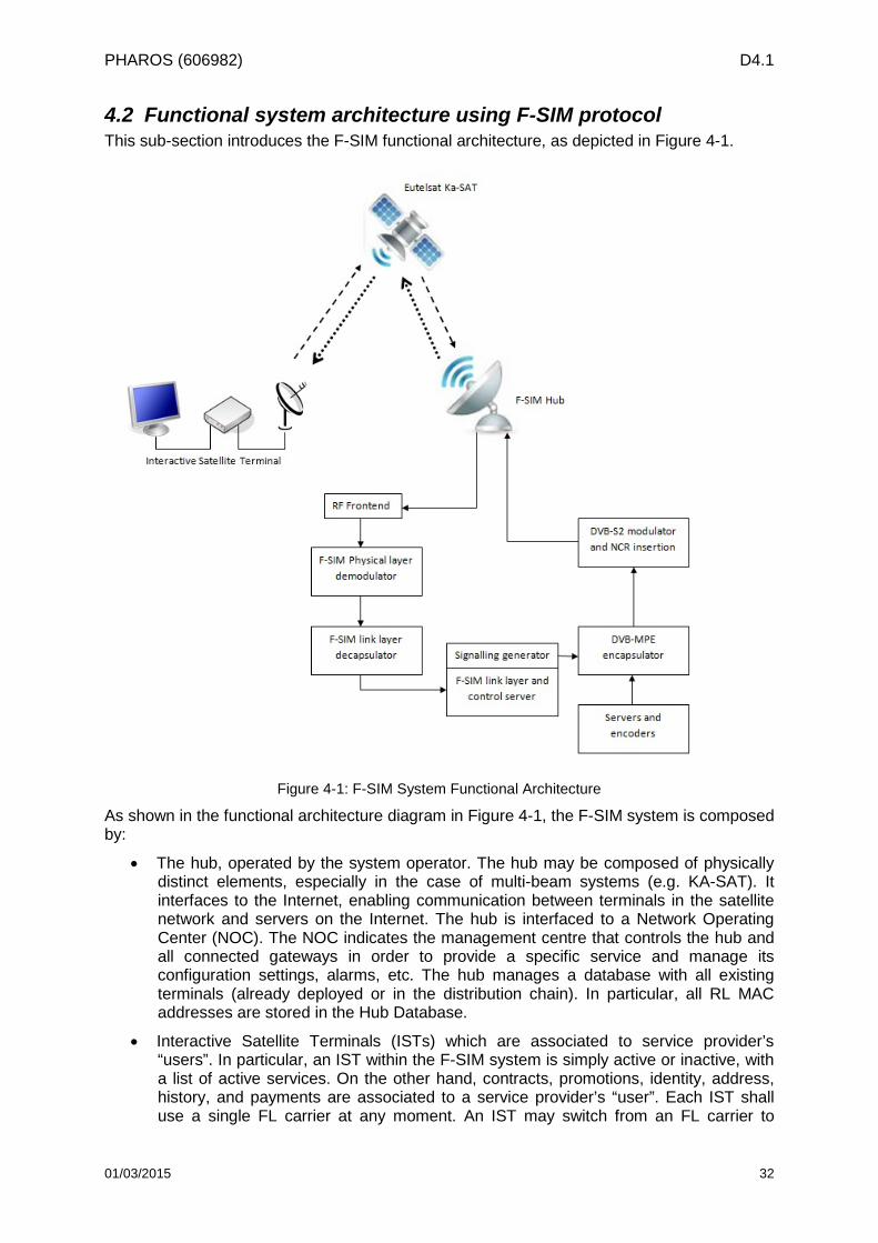
PHAROS (606982) D4.1
4.2 Functional system architecture using F-SIM protocol This sub-section introduces the F-SIM functional architecture, as depicted in Figure 4-1.
Figure 4-1: F-SIM System Functional Architecture
As shown in the functional architecture diagram in Figure 4-1, the F-SIM system is composed by:
• The hub, operated by the system operator. The hub may be composed of physically distinct elements, especially in the case of multi-beam systems (e.g. KA-SAT). It interfaces to the Internet, enabling communication between terminals in the satellite network and servers on the Internet. The hub is interfaced to a Network Operating Center (NOC). The NOC indicates the management centre that controls the hub and all connected gateways in order to provide a specific service and manage its configuration settings, alarms, etc. The hub manages a database with all existing terminals (already deployed or in the distribution chain). In particular, all RL MAC addresses are stored in the Hub Database.
• Interactive Satellite Terminals (ISTs) which are associated to service provider’s “users”. In particular, an IST within the F-SIM system is simply active or inactive, with a list of active services. On the other hand, contracts, promotions, identity, address, history, and payments are associated to a service provider’s “user”. Each IST shall use a single FL carrier at any moment. An IST may switch from an FL carrier to
01/03/2015 32
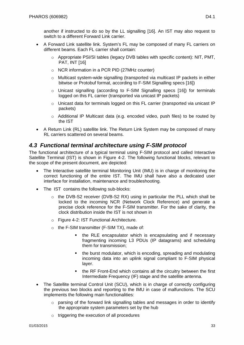
PHAROS (606982) D4.1
another if instructed to do so by the LL signalling [16]. An IST may also request to switch to a different Forward Link carrier.
• A Forward Link satellite link. System’s FL may be composed of many FL carriers on different beams. Each FL carrier shall contain:
o Appropriate PSI/SI tables (legacy DVB tables with specific content): NIT, PMT, PAT, INT [16]
o NCR information in a PCR PID (27MHz counter)
o Multicast system-wide signalling (transported via multicast IP packets in either bitwise or Protobuf format, according to F-SIM Signalling specs [16])
o Unicast signalling (according to F-SIM Signalling specs [16]) for terminals logged on this FL carrier (transported via unicast IP packets)
o Unicast data for terminals logged on this FL carrier (transported via unicast IP packets)
o Additional IP Multicast data (e.g. encoded video, push files) to be routed by the IST
• A Return Link (RL) satellite link. The Return Link System may be composed of many RL carriers scattered on several beams.
4.3 Functional terminal architecture using F-SIM protocol The functional architecture of a typical terminal using F-SIM protocol and called Interactive Satellite Terminal (IST) is shown in Figure 4-2. The following functional blocks, relevant to the scope of the present document, are depicted:
• The Interactive satellite terminal Monitoring Unit (IMU) is in charge of monitoring the correct functioning of the entire IST. The IMU shall have also a dedicated user interface for installation, maintenance and troubleshooting.
• The IST contains the following sub-blocks:
o the DVB-S2 receiver (DVB-S2 RX) using in particular the PLL which shall be locked to the incoming NCR (Network Clock Reference) and generate a precise clock reference for the F-SIM transmitter. For the sake of clarity, the clock distribution inside the IST is not shown in
o Figure 4-2: IST Functional Architecture.
o the F-SIM transmitter (F-SIM TX), made of:
the RLE encapsulator which is encapsulating and if necessary fragmenting incoming L3 PDUs (IP datagrams) and scheduling them for transmission;
the burst modulator, which is encoding, spreading and modulating incoming data into an uplink signal compliant to F-SIM physical layer.
the RF Front-End which contains all the circuitry between the first Intermediate Frequency (IF) stage and the satellite antenna.
• The Satellite terminal Control Unit (SCU), which is in charge of correctly configuring the previous two blocks and reporting to the IMU in case of malfunctions. The SCU implements the following main functionalities:
o parsing of the forward link signalling tables and messages in order to identify the appropriate system parameters set by the hub
o triggering the execution of all procedures
01/03/2015 33
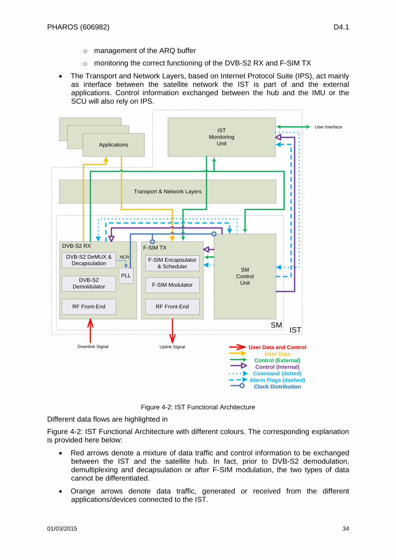
PHAROS (606982) D4.1
o management of the ARQ buffer
o monitoring the correct functioning of the DVB-S2 RX and F-SIM TX
• The Transport and Network Layers, based on Internet Protocol Suite (IPS), act mainly as interface between the satellite network the IST is part of and the external applications. Control information exchanged between the hub and the IMU or the SCU will also rely on IPS.
ApplicationApplication
Applications
IST Monitoring
Unit
User Interface
Transport & Network Layers
SMControl
Unit
Downlink Signal Uplink Signal
IST
User Data and ControlUser Data
Control (External)Control (Internal)
Command (dotted)Alarm Flags (dashed)
Clock Distribution
SM
RF Front-End
F-SIM Modulator
F-SIM Encapsulator & Scheduler
RF Front-End
DVB-S2 Demoldulator
DVB-S2 DeMUX & Decapsulation
DVB-S2 RX F-SIM TX
PLL
NCR
Figure 4-2: IST Functional Architecture
Different data flows are highlighted in
Figure 4-2: IST Functional Architecture with different colours. The corresponding explanation is provided here below:
• Red arrows denote a mixture of data traffic and control information to be exchanged between the IST and the satellite hub. In fact, prior to DVB-S2 demodulation, demultiplexing and decapsulation or after F-SIM modulation, the two types of data cannot be differentiated.
• Orange arrows denote data traffic, generated or received from the different applications/devices connected to the IST.
01/03/2015 34
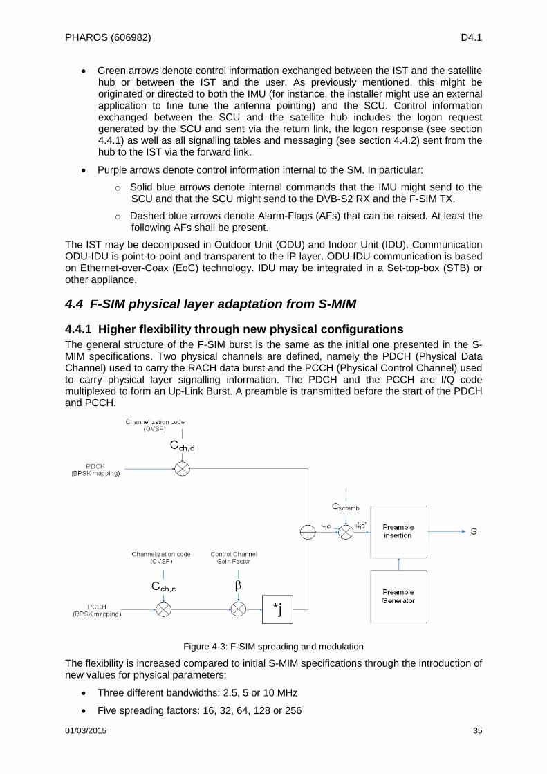
PHAROS (606982) D4.1
• Green arrows denote control information exchanged between the IST and the satellite hub or between the IST and the user. As previously mentioned, this might be originated or directed to both the IMU (for instance, the installer might use an external application to fine tune the antenna pointing) and the SCU. Control information exchanged between the SCU and the satellite hub includes the logon request generated by the SCU and sent via the return link, the logon response (see section 4.4.1) as well as all signalling tables and messaging (see section 4.4.2) sent from the hub to the IST via the forward link.
• Purple arrows denote control information internal to the SM. In particular:
o Solid blue arrows denote internal commands that the IMU might send to the SCU and that the SCU might send to the DVB-S2 RX and the F-SIM TX.
o Dashed blue arrows denote Alarm-Flags (AFs) that can be raised. At least the following AFs shall be present.
The IST may be decomposed in Outdoor Unit (ODU) and Indoor Unit (IDU). Communication ODU-IDU is point-to-point and transparent to the IP layer. ODU-IDU communication is based on Ethernet-over-Coax (EoC) technology. IDU may be integrated in a Set-top-box (STB) or other appliance.
4.4 F-SIM physical layer adaptation from S-MIM
4.4.1 Higher flexibility through new physical configurations The general structure of the F-SIM burst is the same as the initial one presented in the S-MIM specifications. Two physical channels are defined, namely the PDCH (Physical Data Channel) used to carry the RACH data burst and the PCCH (Physical Control Channel) used to carry physical layer signalling information. The PDCH and the PCCH are I/Q code multiplexed to form an Up-Link Burst. A preamble is transmitted before the start of the PDCH and PCCH.
Figure 4-3: F-SIM spreading and modulation
The flexibility is increased compared to initial S-MIM specifications through the introduction of new values for physical parameters:
• Three different bandwidths: 2.5, 5 or 10 MHz
• Five spreading factors: 16, 32, 64, 128 or 256
01/03/2015 35
PHAROS (606982) D4.1
• Six burst sizes: 38, 78, 150, 300, 625 and 1513 bytes
The information relative to the physical configuration used is contained in the PCCH with the field called Transport Format Indication (TFI).
It allows managing many scenarios:
• In case of terminals experiencing an excessive positive link margin they can switch to a higher bitrate with reduced spreading factor. In this case they will be able to transmit packets of larger sizes in less time. For example, in Ka-band multi-spots system with clear sky conditions, the terminal can use spreading factors like 16 or 32. Even if the processing gain is lower compared to spreading factor of 256 (10*log10(16)=12dB and 10*log10(256)=24dB), the higher antenna gain will compensate it.
• At the opposite, it the terminal suffers from a rain event, it has the possibility to use a more robust spreading factor. The processing gain will be higher and can counterbalance the rain attenuation.
• The terminal can choose the optimal burst length according to the kind of service. For example, if the terminal must transmit one short information coming from a sensor, it has the possibility to do it without consuming too much bandwidth. From another side, if the terminal needs to convey a video sequence, it can choose the longest bursts for improving the transmission efficiency.
• The useful bandwidth can be adapted to the available bandwidth into the satellite transponder. As matter of fact, the bandwidth ready for use is dependent on the frequency range and the satellite. In these conditions, it is clearly interesting to provide flexibility relative to the bandwidth for the F-SIM specifications.
However, if the combination of a set of physical parameters results in a burst duration exceeding 300 ms, the associated configuration is not possible due to the introduction of a too big latency in the demodulation process (too high complexity for decoding and interference cancellation).
4.4.2 Specific Adaptations from S-MIM One of the main purposes of the F-SIM protocol is allowing the simultaneous use of different physical configurations described in the section 4.4.1. In order to be able to perform it, the specifications are based on several essential conditions:
• The preamble size is proportional to the Spreading Factor (SF). It means that if we compare two modes using different spreading factors, the ratio of two spreading factors shall be equal to the ratio of the preamble sizes:
( )( )
( )( )2_
1_21
configsizepreambleconfigsizepreamble
configSFconfigSF
=
• With the channelisation operation, data symbols in the so-called I- and Q-branches are independently multiplied with an OVSF code. The control channel at the Q-branch may be adjusted by the gain factor β≤1. The value of this parameter can be chosen according to the burst configuration and the satellite link conditions.
• The stability in terms of clock and frequency shall respect requirements in order to make possible a good demodulation of all packets:
o Internal clock shall be locked to the NCR in the Forward Link and provide a reference with precision better than ±0.25ppm to be used for signal generation and upconversion.
o Central frequency of emitted signal shall be within ±1.5kHz from nominal frequency.
01/03/2015 36
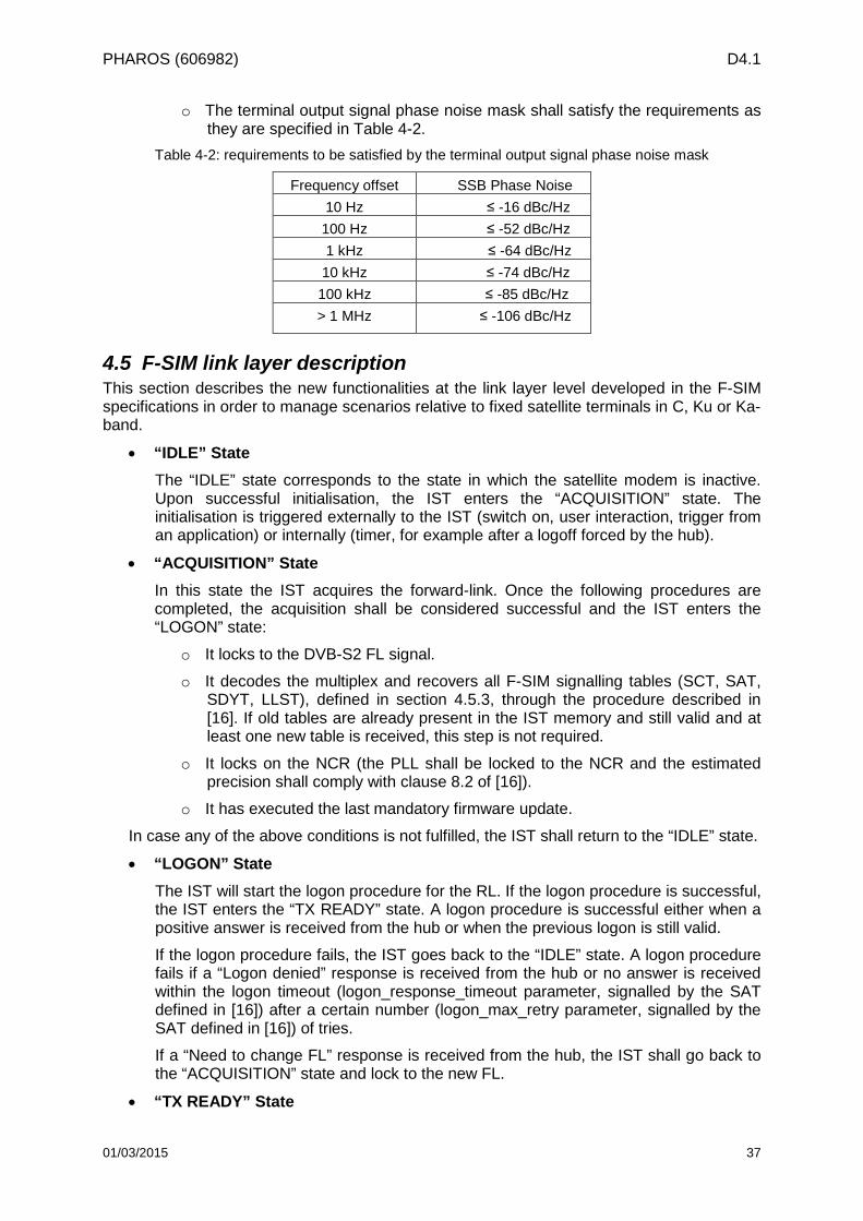
PHAROS (606982) D4.1
o The terminal output signal phase noise mask shall satisfy the requirements as they are specified in Table 4-2.
Table 4-2: requirements to be satisfied by the terminal output signal phase noise mask
Frequency offset SSB Phase Noise 10 Hz ≤ -16 dBc/Hz 100 Hz ≤ -52 dBc/Hz 1 kHz ≤ -64 dBc/Hz 10 kHz ≤ -74 dBc/Hz 100 kHz ≤ -85 dBc/Hz > 1 MHz ≤ -106 dBc/Hz
4.5 F-SIM link layer description This section describes the new functionalities at the link layer level developed in the F-SIM specifications in order to manage scenarios relative to fixed satellite terminals in C, Ku or Ka-band.
• “IDLE” State The “IDLE” state corresponds to the state in which the satellite modem is inactive. Upon successful initialisation, the IST enters the “ACQUISITION” state. The initialisation is triggered externally to the IST (switch on, user interaction, trigger from an application) or internally (timer, for example after a logoff forced by the hub).
• “ACQUISITION” State In this state the IST acquires the forward-link. Once the following procedures are completed, the acquisition shall be considered successful and the IST enters the “LOGON” state:
o It locks to the DVB-S2 FL signal.
o It decodes the multiplex and recovers all F-SIM signalling tables (SCT, SAT, SDYT, LLST), defined in section 4.5.3, through the procedure described in [16]. If old tables are already present in the IST memory and still valid and at least one new table is received, this step is not required.
o It locks on the NCR (the PLL shall be locked to the NCR and the estimated precision shall comply with clause 8.2 of [16]).
o It has executed the last mandatory firmware update.
In case any of the above conditions is not fulfilled, the IST shall return to the “IDLE” state.
• “LOGON” State The IST will start the logon procedure for the RL. If the logon procedure is successful, the IST enters the “TX READY” state. A logon procedure is successful either when a positive answer is received from the hub or when the previous logon is still valid.
If the logon procedure fails, the IST goes back to the “IDLE” state. A logon procedure fails if a “Logon denied” response is received from the hub or no answer is received within the logon timeout (logon_response_timeout parameter, signalled by the SAT defined in [16]) after a certain number (logon_max_retry parameter, signalled by the SAT defined in [16]) of tries.
If a “Need to change FL” response is received from the hub, the IST shall go back to the “ACQUISITION” state and lock to the new FL.
• “TX READY” State
01/03/2015 37
PHAROS (606982) D4.1
In the “TX READY” state the IST is allowed to send data traffic over the RL following the procedure described in [16]. Transmission can be remotely disabled by the hub, or by the IST, in which case the IST enters the “RX ONLY” state. In case the logon expires (timeout), the IST goes back to the “LOGON” state. If the IST is forced to logoff by the IST or by the hub, it goes back to the “IDLE” state.
• “RX ONLY” State In the “RX ONLY” state the IST is not allowed to send data traffic over the RL but it continues receiving and decoding the FL signal. Transmission can be remotely enabled by the hub, or by the IST, in which case the IST enters the “TX READY” state. If the transmission was disabled by the hub, then it has to be re-enabled by the hub and if it was disabled by the IST, then the IST shall re-enable it. In case the logon expires (timeout), the IST goes back to the “LOGON” state. If the IST is forced to logoff by the IST or by the hub, it goes back to the “IDLE” state.
4.5.1 Logon procedure This section describes the logon procedure to access the return link for the terminal. This is the first necessary step for the terminal to connect to the satellite network. The logon procedure is driven by different parameters described in this section. The logon procedure is composed of three main algorithms: the cold logon, the warm logon and the beam search logon.
• Beam search logon
This type of logon shall be executed in multi-spot beam coverage if the interactive satellite terminal does not have a specific beam to access the return link. Its purpose is to identify, with the help of the hub, the correct return link beam. In this type of logon, the satellite terminal is attempting to log onto all possible carriers with increasing transmitted power levels until it gets a response from the hub. The response from the hub might indicate a successful login but it might also indicate the need to change the forward link carrier or to execute a tuning of the beam selection. In the first case, the satellite terminal will go back to the acquisition state, lock onto the new forward link carrier and initiate a new logon. In the second case, the response from the hub will contain a list of carriers the satellite terminal should use to refine its logon, since the fact that the hub was able to decode a logon request sent via a certain carrier does not mean that this is the best possible carrier for that terminal. Therefore, the satellite terminal shall send logon requests in all carriers indicated by the hub with the same power level, until it gets a positive response from the hub.
• Cold logon
A satellite terminal shall perform a cold logon when the previous logon is no longer valid but the satellite terminal has a carrier which is compatible with the current signalling. Typically this happens after its installation or reset. The cold logon shall be also executed upon failure of a warm logon.
• Warm logon
The warm logon is similar to the cold logon except that the power control mechanism to be used is the one specified in the signalling tables through the power control strategy for the chosen physical configuration corresponding to the logon service. For all remaining parameters, the satellite terminal relies on the last known configuration. Typically the warm logon is executed periodically upon expiration of the previous logon facility to allow refreshing some information.
01/03/2015 38
PHAROS (606982) D4.1
4.5.2 F-SIM signalling This section describes the tables sent to the terminal via the forward link allowing giving to the terminal the necessary parameters for reception and transmission.
The SSA Configuration Table (SCT) is used to signal the parameters of the full set of available transmission formats that can be used by the F-SIM TX and the characteristics of the full set of RL beams and carriers.
The SSA Access Table (SAT) contains the full list of the available service classes and the related QoS and load control parameters. It also establishes a correspondence between service classes, RL carrier pools in which those services are authorised, and the subset of transmission formats that can be used within each carrier pool.
The SSA Dynamic Table (SDYT) provides information about the actual load status and the parameters for the uplink power control. Since this table is sent more frequently and shall be continuously checked by the SM, there will be one SDYT for each RL carrier. After successful logon, the SM shall initially identify the subset of SDYTs relevant to its RL carrier(s). SDYTs not belonging to this subset do not need to be continuously monitored by the SM in the “TX READY”” and “RX ONLY” states.
The Link Layer Service signalling table (LLST) provides the list of allowed IP addresses per service class, together with header compression parameters.
The RLE encapsulation protocol specified in [11] is used in F-SIM to encapsulate all packets that shall be sent in the satellite uplink. The adopted RLE configuration is very similar to S-MIM, only the following changes have been applied:
• The maximum ALPDU size has been extended to 8191 bytes.
• An optional PPDU_label_byte is added to all continuation fragments (S = 0 and E = 0) and used as counter whenever fragmentation takes place.
4.5.3 Power control In this section, a procedure is defined through which the terminal chooses the transmission format and transmission power to be used to send a packet over the return link.
When spread spectrum Aloha is used with interference cancellation at the receiver, the distribution of the power with which the packets are received has a great influence on the maximum achievable spectral efficiency. For example, when all packets use the same modulation and coding, the spectral efficiency is maximised when the reception power of packets follows a uniform distribution in dB. Another example is the case in which all packets are received with the same power. In this case, interference cancellation does not provide any capacity gain compared to a “standard receiver” without interference cancellation. Hence, in order to guarantee an efficient use of the spectrum it is necessary to devise a mechanism which allows controlling the distribution of the power with which packets are received at the gateway demodulator.
4.6 F-SIM demodulation process The interest of the F-SIM protocol compared to the S-MIM one is proposing the simultaneous use of different physical configurations. This is possible thanks to an innovative concept of iterative detection, demodulation and cancellation at the demodulator, to reduce multiple-access interference. The Figure 4-4 below presents the required demodulation scheme at the hub when terminals (sharing the same carrier) can use different F-SIM modes.
For the sake of simplicity, the scheme presents only one SIC iteration. The scheme is based on a simple use case with the following conditions:
• 3 spreading factors used in the system (16, 64, 256)
01/03/2015 39
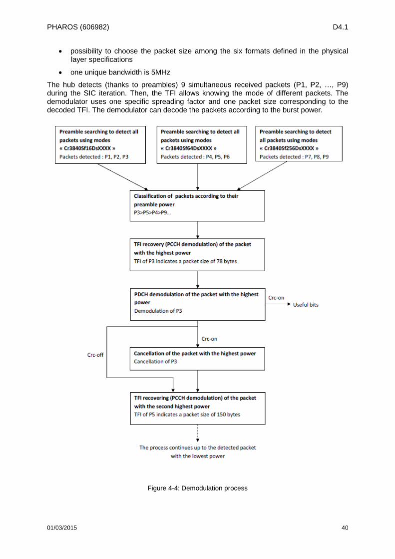
PHAROS (606982) D4.1
• possibility to choose the packet size among the six formats defined in the physical layer specifications
• one unique bandwidth is 5MHz
The hub detects (thanks to preambles) 9 simultaneous received packets (P1, P2, …, P9) during the SIC iteration. Then, the TFI allows knowing the mode of different packets. The demodulator uses one specific spreading factor and one packet size corresponding to the decoded TFI. The demodulator can decode the packets according to the burst power.
Figure 4-4: Demodulation process
01/03/2015 40
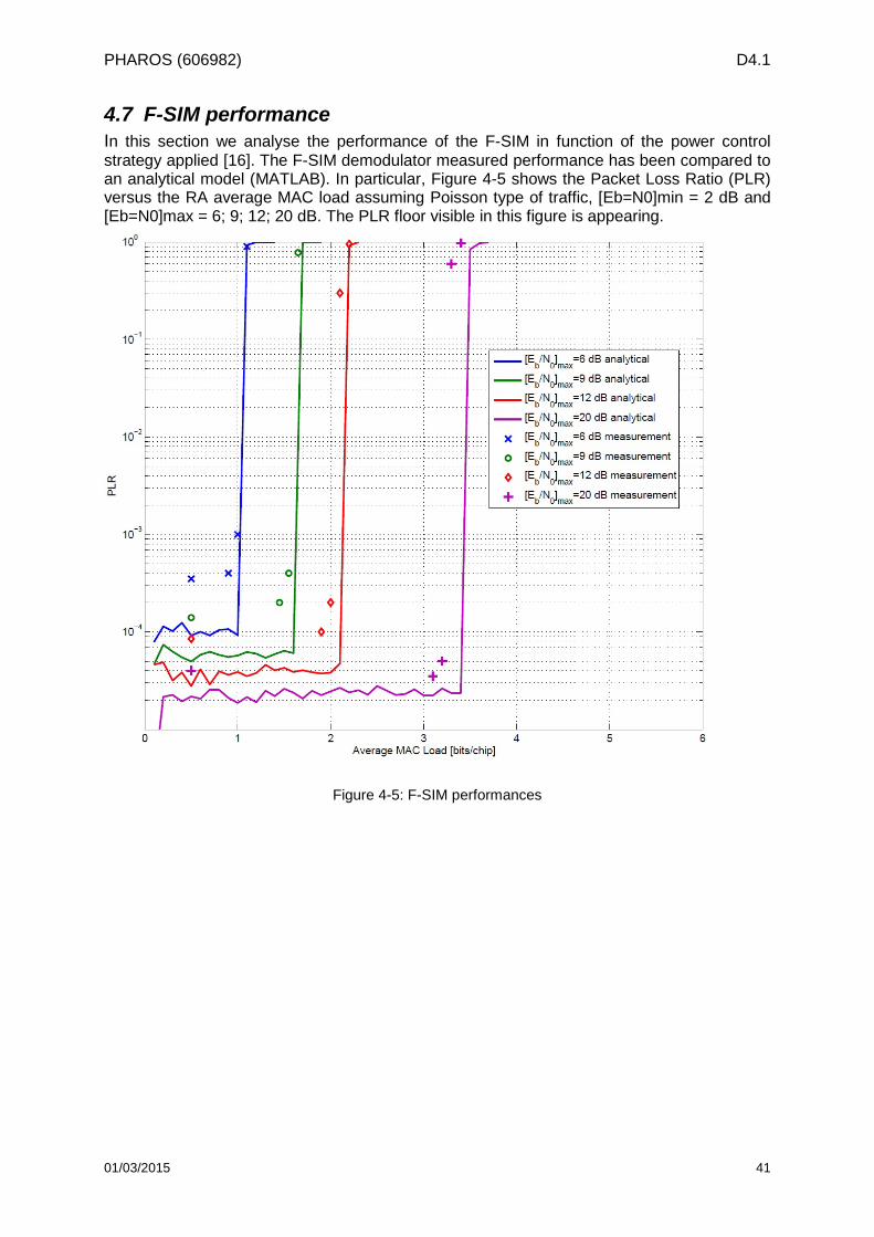
PHAROS (606982) D4.1
4.7 F-SIM performance In this section we analyse the performance of the F-SIM in function of the power control strategy applied [16]. The F-SIM demodulator measured performance has been compared to an analytical model (MATLAB). In particular, Figure 4-5 shows the Packet Loss Ratio (PLR) versus the RA average MAC load assuming Poisson type of traffic, [Eb=N0]min = 2 dB and [Eb=N0]max = 6; 9; 12; 20 dB. The PLR floor visible in this figure is appearing.
Figure 4-5: F-SIM performances
01/03/2015 41
PHAROS (606982) D4.1
5 Interfaces
5.1 FireWatch and F-SIM integration In the forest fire scenario that has been selected as PHAROS use case for the pilot phase, it is foreseen the presence of a satellite terminal that collects data coming from the FireWatch Central (sensor gateway) in a configuration that does not necessarily require mobility for the terminal. Since the terminal is fixed, there is no special constraint to be enforced either on its size or on the energy consumption. This means that, on one hand, higher frequencies can be used, so to grant a higher data rate, and, on the other hand, that it is possible to have higher complexity at the terminal, which, in the specific F-SIM case, can translate into offering a higher level of security (by means of the presence of authentication and encryption schemes) and log in procedures, which can be critical in handling sensitive data such as those which need potentially be transmitted during a forest fire emergency.
In order to assess possible bottlenecks that could derive from the integration of FireWatch with F-SIM within PHAROS, it is useful to briefly review in this section the typical configuration of FireWatch. Each FireWatch Central is managed by a human operator, who can monitor up to 8 sensors (typically 4-6). Different operators may be located in the same physical office; the typical number of operators in an office is 3 or 4. A medium sized network is composed of 100 sensors (Brandenburg, approx. 30.000km2) which are controlled by 6 FireWatch Centrals. In comparison with the raw data coming from the sensors, data from the FrieWatch Central to the service platform is highly compressed and finally processed so that for the transmission of alerts a smaller bandwidth is sufficient.
The typical sizes of the payload sent from the sensor to the FireWatch centrals varies and depends on the type of message that is meant to be sent, as listed in the following:
• Alert Message : 10 KB • Image: 100 KB • High Definition (HD) Image (on demand from operators): 300 KB
In the PHAROS short term approach, the FireWatch central is connected to a single sensor network composed of 6 optical sensors. These sensors transmit up to 300 times per day; however, if no smoke is detected, no transmission takes place. The number of transmissions depends also on the type of message that is being sent, typically large sized images are sent only upon request of an operator and do not exceed 2 transmissions per day, as reported in Table 5-2. Neither the sensors nor the FireWatch centrals are mobile.
Moreover, given that a set of actions comprising verification, bearing, triangulation, decision process, etc., should be carried by each single operator, the operators could only in theory handle one alert every 1-3 minutes. Only validated alerts are transmitted over the F-SIM channel to the service platform.
The F-SIM standard allows the transmission of messages with different payload sizes, however, given the relatively large size of the messages that are sent from the sensor to the central, it is reasonable to send the largest possible sized fragment over the F-SIM channel, which is 1513 Bytes. Table 5-1 shows all the possible F-SIM configurations, when a packet of such length is considered. Moreover, assuming that it is of interest to send the message from the FireWatch Central to the Service Platform as fast as possible, the correspondent bandwidth and burst duration of the relative configuration are as follows:
• Info byte/burst: 1513 B
• Bandwidth: 10 MHz
• Burst duration: 75 ms
01/03/2015 42
PHAROS (606982) D4.1
Table 5-1: possible F-SIM configurations, when a burst length of 1513 B is selected
Info Byte [B] 1513 1513 1513 Bandwidth [MHz] 2.5 5 10 Spreading Factor 16 16 32 16 32 64 Burst Duration [ms] 300 150 300 75 150 300
With this packet length, in order to be transmitted over the satellite channel, the messages are divided respectively in 7 fragments for an Alert Message, 70 for a normal definition image and 200 for an HD image. The transmission time, when no retransmission protocols are considered, is also reported in Table 5-2. As it can be observed, the large number of fragments to be sent for a HD image, or even a normal image, suggests that employing resizing and coding strategies, to reduce the size of the packets, would be beneficial, as well as the adoption of an ARQ strategy. Table 5-2 suggests which technique could be employed, so to ensure a reliable transmission, when different typologies of alert are considered.
Table 5-2: Summary of sensor messages characteristics, when a specific F-SIM configuration is selected (Bandwidth 10MHz, info byte/burst 1513 B, burst duration 75 ms)
# TX per day
Payload size
# Frames required
TX time Technique required
Alert 0-300 10 KB 7 0.5 [s] ARQ Image 0-300 100 KB 70 5 [s] ARQ HD Image 0-2 300 KB 200 15 [s] ARQ, coding, resizing
5.2 FireWatch Interface Due to its completely IP-based concept, the FireWatch system could be easily connected to an existing IP-network. The internal traffic from the optical sensors (camera), other sensors to be added (e.g. weather sensors, as depicted in Figure 5-1) and sensor networks is transferred via a private network (e.g. 192.168.0.0, 10.0.0.0) by means of radio or wired connections. All external traffic is transferred via separate VPN-connections to ensure a high security level.
A separate WAN-port of the existing router at the FireWatch control office is configured for the connection of the Sensor Gateway to the PHAROS platform via the satellite terminal using TCP/IP connection. The properties of the needed interface are summarised in Table 5-3.
01/03/2015 43
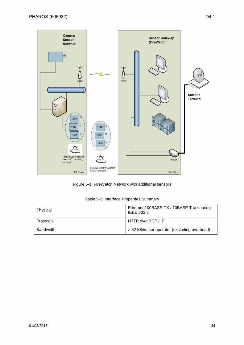
PHAROS (606982) D4.1
Figure 5-1: FireWatch Network with additional sensors
Table 5-3: Interface Properties Summary
Physical Ethernet 100BASE-TX / 10BASE-T according IEEE 802.3
Protocols HTTP over TCP / IP
Bandwidth > 52 kBit/s per operator (excluding overhead)
01/03/2015 44
PHAROS (606982) D4.1
6 Conclusions This section provides the conclusion of the work carried out within the task dedicated to the satellite based messaging up link for in-situ sensor networks. An important aspect to take into consideration regards the reasons which have led to select a satellite system for the communication between the sensors responsible for the collection of data in the fire scenario that has been considered, and the service platform. Those reasons lie in the natural resilience that a satellite system can offer against earthly disasters, which can prove to be an essential resource in disparate emergency scenarios in every phase of the disaster management cycle. However, the importance of alternative solutions to carry through this communication is not undervalued. It is this the reason why, given also the modular and flexible approach that has been followed for the design of PHAROS, a number of potential alternatives, both satellite and terrestrial, has been reviewed as plausible parts of the PHAROS picture, possibly for the long term approach. Likewise, in order to give the same flexible fashion to each component of the chain, a number of sensor based technologies has been reviewed.
As a second step, the selection of two specific technologies, FireWatch and F-SIM, responsible for the collection of sensor data and the communication via satellite between the emergency location and the Service Platform, respectively, has been made and justified. In particular, FireWatch is a system that enables early fire recognition in large open areas, thanks to its smoke detection capabilities, and is therefore particularly suited for the type of scenario of interest in PHAROS. Furthermore, F-SIM, a protocol developed mainly for the return link messaging, copes perfectly with the bursty transmission typical for emergency alert notification, and its selection allows for very low Packet Error Rate against an affordable implementation complexity. Additionally, the low cost user terminals favour an easy adoption of the PHAROS platform in the context of multi-hazard prevention.
01/03/2015 45
PHAROS (606982) D4.1
7 References [1] J. Mulero Chaves (Ed.), “PHAROS Deliverable D2.9: PHAROS System Architecture –
Final”, submitted in November 2014.
[2] J. Mulero Chaves (Ed.), “PHAROS Deliverable D2.5: PHAROS Requirements and System Engineering – Second Issue”, submitted in February 2015.
[3] P. Burgos (Ed.), “PHAROS Deliverable D2.2: Business Model Spreadsheet and Business Plan Report – Draft”, to be submitted in February 2015.
[4] P. Burgos (Ed.), “PHAROS Deliverable D2.3: Business Model Spreadsheet and Business Plan Report – Final”, to be submitted in September 2015.
[5] J. Mulero Chaves (Ed.), “PHAROS Deliverable D2.4: PHAROS Requirements and System Engineering – First Issue”, submitted in July 2014.
[6] J. Mulero Chaves (Ed.), “PHAROS Deliverable D2.1: PHAROS Service Concept Specification”, submitted in July 2014.
[7] R. Schneeman: “Implementing a Standards-based Distributed Measurment and Control Application on the Internet“, NIST 1999
[8] R. Schneeman, K. Lee, “Multi-Network Access to IEEE P.1451 Smart Sensor Information Using World Wide Web Technology“, NIST
[9] H. Poor, “An Introduction to Signal Detection and Estimation“, New York: Springer-Verlag, 1985, ch. 4.
[10] O. Hersent, D. Boswarthick, O. Elloumi, “The Internet of Things, Key Applications and Protocols”, Wiley, 2012.
[11] Eutelsat Technical Specifications, "Satellite Earth Stations and Systems; Air Interface for Fixed Satellite Interactive Multimedia (F-SIM); Part 3: Physical Layer Specification, Return Link Asynchronous Access", Version 1.02.01, 2013.
[12] S. Matthews, A. Sullivan, J. Gould, R. Hurley, P. Ellis, J. Larmour Number, “Evaluation of three fire detection systems“ CSE-BDA-002, Bushfire Cooperative Research Centre Prepared, 2010.
[13] D. Schroeder , “Evaluation of three wildfire smoke detection systems“, FERIC report, vol.5, No.24, 2004.
[14] A. Nowzad et al., “Development of an Automatic Smoke Detection Algorithm using Color Images and a Fuzzy Logic Approach for Real-Time Forest Fire Detection Applications“, 5th International Conference on Automatic Fire Detection, Duisburg, Germany, 14. - 16. October 2014.
[15] G. Gardikis (Ed.), “PHAROS Deliverable D5.3: Interfaces and Service Gateway Design Document”, submitted in January 2015.
[16] Eutelsat Technical Specifications, "Air Interface for Fixed Satellite Interactive Multimedia (F-SIM): Link Layer and System Signalling Specification", 1.7, July 2014.
01/03/2015 46