Embed Size (px)
Citation preview

ST3000 Autopilot
ST3000 Autopilot Service Manual 83004-2 1
Warning
CE Marking of Equipment/Replacement Parts
If the Autohelm equipment under repair, test, calibration, installation or setting to work carries the European CE mark,only parts and components supplied or approved for such use by Raytheon should be used in order to maintain
compliance with the relevant CE requirements.
Incorporation, use or attachment, by any means, of parts or components not supplied for or not approved for such use byRaytheon or, if supplied or approved for use by Raytheon, not properly fitted in accordance with instructions published,
provided or recommended by Raytheon, may cause the equipment to malfunction and, in particular, to become unsafe orto no longer meet the relevant CE requirements. In these circumstances, Raytheon Marine Europe Ltd excludes liability
to the fullest extent permissible in law for any loss or damage including any liability for its contribution to such loss ordamage by its negligent acts or omissions .
Z155, ST3000 AutopilotService Manual
D296

ST3000 Autopilot
2 ST3000 Autopilot Service Manual 83004-2
Chapter 1. Before DismantlingBefore dismantling the autohelm ST3000 check the phase of the autopilot (IfPCB condition allows) by driving the pilot, in standby mode, with the coursechange keys.
+10 key –10 key
Aft facing actuator Clockwise actuator rotation Anticlockwise actuator rotation
Forward facing actuator Anticlockwise actuator rotation Clockwise actuator rotation
All new spares PCBs are factory set to operate the pilot with the drive unitfacing aft. A replacement PCB for an installation with the drive unit facingforward requires resetting.
To reset the operating sense press the +1° and -1° course keys together for5 seconds.
The unit beeps for 10 seconds to confirm changeover and the display showsthe new setting, either ‘Port’ (actuator sprocket facing forward) or ‘Starb’(actuator sprocket facing aft’).
The autopilot may be calibrated t to suit a particular vessel. Note thecalibration settings and set up the new PCB if required.
If the spares PCB contains software of a higher issue than before then therelevant Operating Supplement must be supplied when the equipment isreturned to the customer.
Note: Replacement PCBs require setting up to ST3000.Refer to Autopilot type selection on page 3 for instructions.
ST3000 Autopilot
ST3000 Autopilot Service Manual 83004-2 3
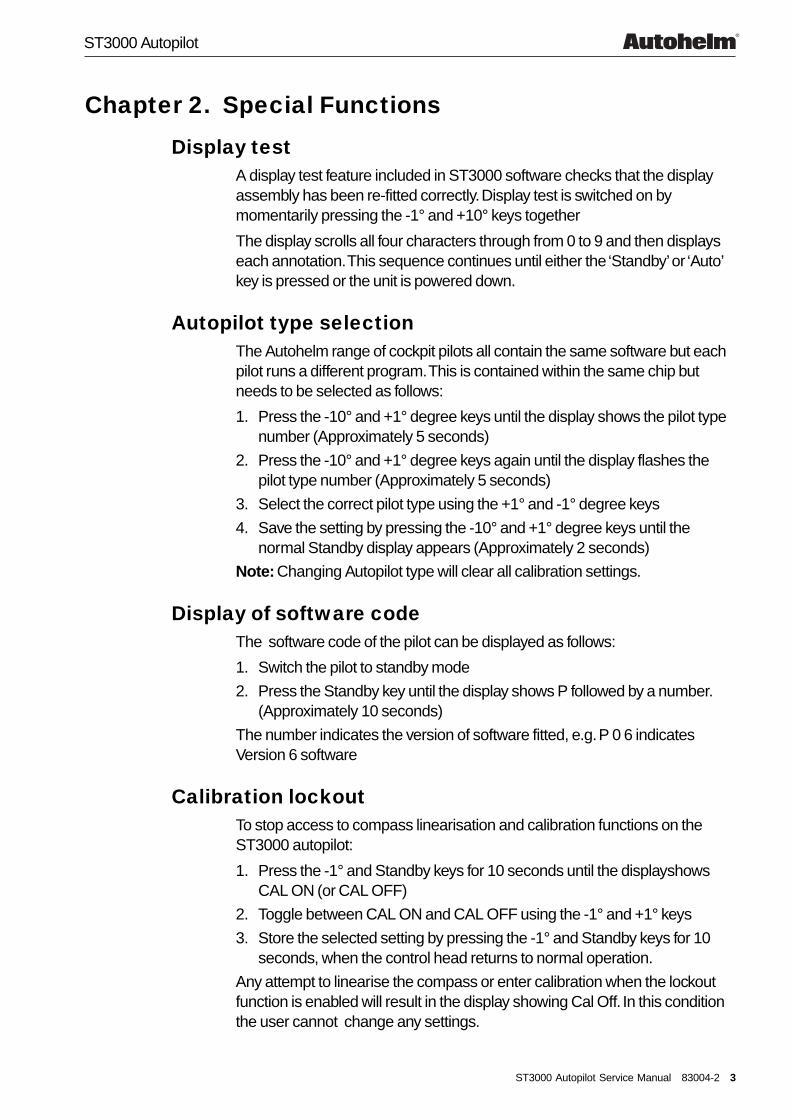
Chapter 2. Special Functions
Display testA display test feature included in ST3000 software checks that the displayassembly has been re-fitted correctly. Display test is switched on bymomentarily pressing the -1° and +10° keys together
The display scrolls all four characters through from 0 to 9 and then displayseach annotation. This sequence continues until either the ‘Standby’ or ‘Auto’key is pressed or the unit is powered down.
Autopilot type selectionThe Autohelm range of cockpit pilots all contain the same software but eachpilot runs a different program. This is contained within the same chip butneeds to be selected as follows:
1. Press the -10° and +1° degree keys until the display shows the pilot typenumber (Approximately 5 seconds)
2. Press the -10° and +1° degree keys again until the display flashes thepilot type number (Approximately 5 seconds)
3. Select the correct pilot type using the +1° and -1° degree keys
4. Save the setting by pressing the -10° and +1° degree keys until thenormal Standby display appears (Approximately 2 seconds)
Note: Changing Autopilot type will clear all calibration settings.
Display of software codeThe software code of the pilot can be displayed as follows:
1. Switch the pilot to standby mode
2. Press the Standby key until the display shows P followed by a number.(Approximately 10 seconds)
The number indicates the version of software fitted, e.g. P 0 6 indicatesVersion 6 software
Calibration lockoutTo stop access to compass linearisation and calibration functions on theST3000 autopilot:
1. Press the -1° and Standby keys for 10 seconds until the displayshowsCAL ON (or CAL OFF)
2. Toggle between CAL ON and CAL OFF using the -1° and +1° keys
3. Store the selected setting by pressing the -1° and Standby keys for 10seconds, when the control head returns to normal operation.
Any attempt to linearise the compass or enter calibration when the lockoutfunction is enabled will result in the display showing Cal Off. In this conditionthe user cannot change any settings.

ST3000 Autopilot
4 ST3000 Autopilot Service Manual 83004-2
Chapter 3. Functional Test
Overall function
Change motor.Restart.
Change faultyitem(s). Restart.
Connect actuator toControl Head and apply
power to unit
Hold unit vertical. Rotate it in clockwise
direction; check actuatorrotates anti-clockwise
(STBD set up) orclockwise (PORT set up)
Check fluxgate(SECT 5.6)
No
Yes
OKChange PCB.
Restart.
Unit beeps, and shows 3000 and then displays a magnetic
heading, with flashing 'C'
Press & Hold +10 key.Check motor runs.
OKNo
Yes
Press & Hold -10 key.Check actuator runs.
Disconnect power andremove drive module.
Disconnect motor spadeterminals and apply 10V DCto motor terminals. Check
motor runs. (See Figure 3).
OK
Press AUTO and checkdisplay shows 'A'
followed by a heading.
OK
Change PCB.Restart.OK
No
Yes
Change motor.Restart.
No
Yes
OK
Hold unit vertical, rotateit an anti-clockwise direction;
check actuator rotatesclockwise (STBD set up) or
anti-clockwise (PORT set up)
OK
Unit OK
No
Yes
No
Yes
OKNo
Yes
Change PCB.Restart.
Change fluxgate.Restart.
No
Yes
OK
Reverse 10V on motor.Check motor runs.
Check motor connectionsand wires.
OK
Change PCB.Restart.
No
Yes
No
Yes
D4103-1

ST3000 Autopilot
ST3000 Autopilot Service Manual 83004-2 5
Fluxgate compass assemblyRemove the fluxgate assembly (see Figure 2).
The compass can be checked with a DVM as follows:
Connect meter across Resistance
1 and 2 <10 ohms
3 and 5 < 5 ohms
3 and 4 < 5 ohms
1 and 3 Open circuit
D4104-1
12
34
5
No connection
Figure 1. Fluxgate electrical connections

ST3000 Autopilot
6 ST3000 Autopilot Service Manual 83004-2
Chapter 4. Disassembly/Assembly
SeaTalk Deck Plug
Screw (x2)
Pin carrier
Plug pin screw (x3)
Plug pin (x3)
Metal sleeve (x3)
Brown wireBlue wire
Yellowwire
Plug body
Cableclamp
Cableseal
Clampnut
Cable assembly(3016-104)
D4107-1
Assemble sleeve to wire. Pinch sleeve with pliers. Insertsleeve into plug pin and tighten screw to retain. Cut off excess metal sleeve to prevent short circuit.Repeat process for remaining wires.
Electrical connections
Wire colour Description
Brown +12V nominal supply
Blue 0V supply
ST3000 Autopilot Display Unit
Spare parts list
The item numbers refer to Figure 2: ST3000 Autopilot display unit.
Item Spare Description Part No. Comments
– Control Head Q056 Complete head
LCD kit, including Q0534 LCD surround5 LCD6 Elastomer7 Diffuser8 Reflector27 Locking wedge (x5)
9 PCB assembly Q044 LCD not included
13 Fluxgate assembly M022
30 SeaTalk deck plug assembly D326

ST3000 Autopilot
ST3000 Autopilot Service Manual 83004-2 7
Not
es:
A. K
eypa
ds c
ome
bond
ed to
faci
a on
late
r un
its.
B. E
nsur
e th
at th
e flu
xgat
e lo
om is
form
ed a
roun
d th
e ou
tsid
e
of t
he r
ear
case
pill
ar. F
ailu
re to
do
so m
ay r
esul
t in
the
g
imba
l act
ion
bein
g im
paire
d an
d th
e au
topi
lot p
erfo
rman
ce
deg
rade
d.C
. Ear
ly p
rodu
ctio
n un
its h
ave
a sp
acer
(29
) w
hich
is e
ffect
ivel
y
rep
lace
d by
usi
ng 4
wed
ges
(27)
on
late
r un
its.
129
(N
ote
C)
45
67
89
27 (
x4)
2 (x
6)(N
ote
A)
3 (x
6)28
1014
16 17 18 19 20
15 (
x4)
21 22 23 24 25 26
Not
e B
1. F
acia
2. K
eypa
d (x
6) 3
. Act
uato
r (x
6) 4
. LC
D s
urro
und
5. L
CD
6. E
last
omer
con
nect
or 7
. Diff
user
8. R
efle
ctor
9. P
CB
10. S
eal
11. G
imbo
l sup
port
(x2
)12
. Gim
bol s
uppo
rt s
crew
(x2
)13
. Flu
xgat
e as
sem
bly
14. R
ear
case
15. C
ase
scre
w (
x4)
16. F
luxg
ate
grou
nd
Inse
rt w
edge
(27
) as
sho
wn
to s
ecur
e di
spla
y be
zel l
eg
Wed
ge (
27)
PC
B (
9)
Dis
play
beze
l (4)
Ear
ly u
nits
Late
r un
its
Impo
rtan
t: T
he fl
uxga
te lo
om in
som
eea
rly u
nits
is w
ired
diffe
rent
ly.
17. F
luxg
ate
driv
e18
. Flu
xgat
e se
nse
B19
. Flu
xgat
e se
nse
com
mon
20. F
luxg
ate
sens
e A
21. S
eaT
alk
data
(ye
llow
)22
. Shi
eld
(scr
een
- bl
ack
slee
ve)
23. +
12V
sup
ply
(bro
wn)
24. G
roun
d (b
lue)
25. M
otor
(bl
ack)
26. M
otor
(re
d)27
. Wed
ge (
x4)
28. S
him
29. S
pace
r (e
arly
uni
ts o
nly)
30. S
eaT
alk
deck
plu
g as
sem
bly
11 (x
2)12
(x2
)13
D41
01-1
30
Figure 2: ST3000 Autopilot display unit

ST3000 Autopilot
8 ST3000 Autopilot Service Manual 83004-2
ST3000 Drive Actuator
Spare parts list
The item numbers refer to Figure 3: ST3000 Autopilot drive actuator.
Item Spare Description Part No. Comments
– ST3000 drive module Q45 Complete drive
ST3000Gearbox/Driveassembly, including Q102
1 Pin2 Clutch flange3 Gearbox housing4 Seal
2,1 Clutch flange & pin H006 Also part of Q102
7 Motor Q101
10 Pod H001
Motor replacement
If the gearbox is noisy when the motor is replaced, remove motor, rotategearbox a small amount, and refit.

ST3000 Autopilot
ST3000 Autopilot Service Manual 83004-2 9
D41
02-1
Pip
Blu
e(M
2)B
row
n(M
1)
Blu
e(M
2)
Bro
wn
(M1)
Red
dot
12
34
57
6
89
10
1716
15
11 12 13 14
1. P
in2.
Clu
tch
flang
e3.
Gea
rbox
hou
sing
4. S
eal
5. F
lux
ring
6. L
ocat
ion
scre
w7.
Driv
e m
otor
8. C
ap9.
Sea
l
10. P
od11
. Shr
oud
12. G
rip13
. Sea
l14
. Loc
atio
n rin
g15
. Rec
epta
cle
16. S
ocke
t17
. 'O
' rin
g
Not
e:C
onne
ct a
10v
dc
supp
ly to
the
actu
ator
pl
ug a
nd m
easu
re th
e ru
nnin
g cu
rren
t of
the
driv
e un
it.<
2A
- D
rive
heal
thy
> 2
A -
Driv
e fa
ulty
Figure 3. ST3000 Drive Actuator

ST3000 Autopilot
10 ST3000 Autopilot Service Manual 83004-2
Chapter 5. PCB Details
D4108-1
Figure 4: Circuit Diagram

ST3000 Autopilot
ST3000 Autopilot Service Manual 83004-2 11
PCB Layout
D4105-1Taken from Drawing No: 4155-010 Issue: J Date: 07.03.97
Figure 5: PCB Component Layout

ST3000 Autopilot
12 ST3000 Autopilot Service Manual 83004-2
PCB Component list
D4106-1Taken from Drawing No: 4155-010 Issue: J Date: 07.03.97
Raytheon Marine Company676 Island Pond RoadManchesterNew Hampshire 03109-5420
Tel: (001 603) 647 7530Fax: (001 603) 634 4756
Raytheon Marine Europe LimitedAnchorage Park, PortsmouthHampshire PO3 5TD
Tel: (01705) 693611Fax: (01705) 694642http: //www.raytheon.com