Embed Size (px)
Citation preview

PROPRIETARY RIGHTS STATEMENT This document contains information, which is proprietary to the NEWCOM# Consortium.
Network of Excellence
NEWCOM#
Network of Excellence in Wireless Communications#
FP7 Contract Number: 318306
WP 2.3 – Flexible communication terminals and net-works
D23.4
Final results obtained in the lab infrastructures
Contractual Delivery Date: October 31, 2015 Actual Delivery Date: November 20, 2015 Responsible Beneficiary: CNRS/EURECOM Contributing Beneficiaries: CNIT, Bilkent, INOV, TUD Estimated Person Months: 15 Dissemination Level: Public Nature: Report Version: 1.0
Ref. Ares(2015)5420898 - 27/11/2015

PROPRIETARY RIGHTS STATEMENT This document contains information, which is proprietary to the NEWCOM# Consortium.
This page is left blank intentionally

FP7 Contract Number: 318306 Deliverable ID: WP2.3 / D2.3.3
Distribution Level: Public Page 3
Document Information
Document ID: D23.4 Version Date: November 15, 2015 Total Number of Pages: 33 Abstract: Final report on tools and their integration on the experimental
setups: Description of the hardware and software developments carried out by the partners during the final year of the NoE and their integration into the three experimental setups. Final report on dissemination activities.
Keywords: EuWin, EURECOM, OpenAirInterface, experimental research, cloud RAN, TVWS, 4G/5G coexistence, localization, channel reciprocity
Authors
Full Name Beneficiary / Organisation
e-mail Role
Florian Kaltenberger CNRS/Eurecom florian.kaltenberger @eurecom.fr
Editor
Raymond Knopp CNRS/Eurecom [email protected] Contributor
Riadh Ghaddab CNRS/Eurecom [email protected] Contributor
Navid Nikaein CNRS/Eurecom [email protected] Contributor
Geroge Arvanitakis CNRS/Eurecom [email protected] Contributor
Xiwen Jiang CNRS/Eurecom [email protected] Contributor
Carlo Condo CNIT/Polito [email protected] Contributor
Andrea Biroli CNIT/Polito [email protected] Contributor
Guido Masera CNIT/Polito [email protected] Contributor
Carmine Vitiello CNIT/Pisa [email protected] Contributor
Sina Khatibi INOV [email protected] Contributor
Luisa Caeiro INOV [email protected] Contributor
Lucio Studer Ferreira INOV [email protected] Contributor
Luis M. Correia INOV [email protected] Contributor
Lucio Studer Ferreira INOV [email protected] Contributor
Andreas Festag TUD [email protected] Contributor
Martin Dannenberg TUD [email protected]
Contributor
Erdal Arikan Bilkent [email protected] Contributor
Ioannis Dagres IASA [email protected] Contributor
Andreas Polydoros IASA [email protected] Contributor
Oliver Holland KCL [email protected] Contributor
Roberto Verdone CNIT/Bologna [email protected] EuWin Director

FP7 Contract Number: 318306 Deliverable ID: WP2.3 / D2.3.3
Distribution Level: Public Page 4
Reviewers
Full Name Beneficiary / Organisation
e-mail Date
Roberto Verdone CNIT/UniBO [email protected] October 15, 2015 Marco Luise CNIT/UniPI [email protected] November 15, 2015
Version history
Issue Date of Issue Comments 0.1 August 24, 2015 First Draft 0.2 October 15, 2015 Internal review made by the Track Leader 1.0 November 15, 2015 Final version

FP7 Contract Number: 318306 Deliverable ID: WP2.3 / D2.3.3
Distribution Level: Public Page 5
Executive Summary
The objective of Work-package 2.3 is to set up and maintain the EuWIn facilities at Eurecom (EuWIN@CNRS/Eurecom). The general focus is on networked signal processing for collabo-rative communications, development methodologies for massive radio networks in support of the Internet of Things, and technical enablers for white-space exploitation in the presence of a primary communication system. The main “product” of the EuWIN@CNRS/Eurecom lab is the OpenAirInterface.org experi-mental wireless platform. The platform provides an open-source software defined radio solu-tion for 4G networks. The software modem runs on Eurecom’s own hardware target Ex-pressMIMO2 and since October 2014 also on the National Instruments/ETTUS B2x0 and X3x0 targets. The latter development was made possible through a close collaboration with National Instruments. During the course of NEWCOM# the OpenAirInterface platform and software modem has gained significant attention from both industry and academia inside and outside the network. This is partially due to the training and dissemination activities conducted by NEWCOM#. More details and some of the achieved results are reported in this deliverable. This delivera-ble further gives an update on the various joint research actions (JRAs) for the third year.

FP7 Contract Number: 318306 Deliverable ID: WP2.3 / D2.3.3
Distribution Level: Public Page 6
Table of Contents
1. Introduction ......................................................................................................... 8 1.1 Glossary .................................................................................................................. 8 1.2 List of Joint Research Activities (JRAs) ............................................................ 10 1.3 Description of the Main WP Achievemnts in the Reporting Period ................. 10
1.3.1 Most significant results ....................................................................................... 10 1.3.2 Success Stories .................................................................................................. 11 1.3.3 Spreading of results ............................................................................................ 11
2. Detailed Activity and Achieved Results ......................................................... 12 2.1 JRA #1 Cloud RAN ............................................................................................... 12
2.1.1 Description of Activity ......................................................................................... 12 2.1.2 Relevance with the identified fundamental open issues ..................................... 12 2.1.3 Main Results Achieved in the Reporting Period ................................................. 12 2.1.4 Publications ........................................................................................................ 13
2.2 JRA #2 Cellular Broadcasting ............................................................................. 13 2.2.1 Description of Activity ......................................................................................... 13 2.2.2 Relevance with the identified fundamental open issues ..................................... 14 2.2.3 Main Results Achieved in the Reporting Period ................................................. 14 2.2.4 Publications ........................................................................................................ 14
2.3 JRA 3 4G/5G coexistence using spectrum overlay ........................................... 14 2.3.1 Description of Activity ......................................................................................... 14 2.3.2 Relevance with the identified fundamental open issues ..................................... 14 2.3.3 Main Results Achieved in the Reporting Period ................................................. 15 2.3.4 Publications ........................................................................................................ 15
2.4 JRA 4 OAI Lab setup for joint teaching activities ............................................. 16 2.4.1 Description of Activity ......................................................................................... 16 2.4.2 Relevance with the identified fundamental open issues ..................................... 16 2.4.3 Main Results Achieved in the Reporting Period ................................................. 16 2.4.4 Publications ........................................................................................................ 16
2.5 JRA 5 Multihop coding for networks .................................................................. 16 2.6 JRA 6 Localization with distributed antennas ................................................... 16
2.6.1 Description of Activity ......................................................................................... 16 2.6.2 Relevance with the identified fundamental open issues ..................................... 17 2.6.3 Main Results Achieved in the Reproting Period and planned activities .............. 17 2.6.4 Publications ........................................................................................................ 17
2.7 JRA 7 Exploiting Channel Reciprocity in MIMO TDD channels ....................... 17 2.7.1 Description of Activity ......................................................................................... 17 2.7.2 Relevance with the identified fundamental open issues ..................................... 18 2.7.3 Main Results Achieved in the Reporting Period ................................................. 18 2.7.4 Publications ........................................................................................................ 18
3. General Conclusions and Prospects .............................................................. 19
4. Annex I: Detailed Description of Main technical WP Achievements ........... 20 4.1 Implementation of Virtual Radio Resources Management in OAI ................... 20
4.1.1 Introduction ......................................................................................................... 20 4.1.2 OAI extensions to support multiple VNOs/Groups ............................................. 21 4.1.3 Reference Scenario ............................................................................................ 23 4.1.4 Numeric Results ................................................................................................. 24
4.2 UFMC study and experimentation ...................................................................... 26

FP7 Contract Number: 318306 Deliverable ID: WP2.3 / D2.3.3
Distribution Level: Public Page 7
4.3 Localization experiments ..................................................................................... 29

FP7 Contract Number: 318306 Deliverable ID: WP2.3 / D2.3.3
Security: Public Page 8
1. Introduction 1.1 Glossary 3GPP Third generation Partnership ACK Acknowledgement ACLR Adjacent channel leakage ratio ADC Analogue digital convertor AM Acknowledged Mode AMBA Advanced Microcontroller Bus Architecture ASIC Application Specific Integrated Circuit AVCI Advanced VCI BB Baseband BCH Broadcast Channel BE Best Effort BG Best ffort with minimum Guaranteed CCCH Common Control Channel CFI Control Format Indicator CPU Central Processing Unit CQI Channel Quality Indicator CRC Cyclic Redundancy Code CTS Clear to send DAB Digital Audio Broadcast DAC Digital analogue convertor DCCH Dedicated Control Channel DCI Downlink Control Information DD Digital Dividend DDR Double data rate DLSCH Downlink Shared Channel DMA Direct memory access DoW Description of Work DSP Digital Signal Processor DTCH Dedicated Transport Channel EC European commission eNB Enhanced Node B EuWin European Laboratory of Wireless Communications for the Future Internet FDD Frequency division duplex FE Front-end FFT Fast Fourier Transform FPGA Field programmable gate array GPIO General Purpose Input Output GSM Global System for Mobile Communications HARQ Hybrid Automated Repeat Request HI Hybrid ARQ indicator

FP7 Contract Number: 318306 Deliverable ID: WP2.3 / D2.3.3
Security: Public Page 9
IEEE Institute of Electrical and Electronics Engineers IoT Internet of Things IP Internet Protocol JRA Joint Research Activities LNA Low noise amplifier LTE Long term evolution LXRT Linux Real Time MAC Medium access control MIMO Multiple-Input Multiple-Output NAK Non-Acknowledgement NAS Non Access Stratum NFS Network file system NITOS Network Implementation Testbed using Open Source code OAI OpenAirInterface OEDL OMF Experiment Description Language OFDM Orthogonal Frequency division multiplexing OMF cOntrol and Management Framework OS Operating System OSD OpenAir Scenario Descriptor PA Power amplifier PBCH Physical Broadcast Channel PC Personal Computer PCFICH Physical Contrl Format Indicator Channel PCI Peripheral Component Interconnect PCIe PCI express PDCCH Physical Downlink Control Channel PDCP Packet Data Convergence Protocol PDSCH Physical downlink Shared Channel PDU Packed Data Unit PHICH Physical Hybrid-ARQ Indicator Channel PHP Hypertext Preprocessor PHY Physical PMI Precoding Matrix Indicator PRACH Physical Random Access Channel PSS Primary Synchronization Signal PUSCH Physical Uplink Shared Channel RA Random Access RB Resource Block RF Radio frequency RI Rank Indicator RLC Radio Link Controller RRC Radio Resource Controller RRM Radio Resource Manager RTAI Real-time Application Interface

FP7 Contract Number: 318306 Deliverable ID: WP2.3 / D2.3.3
Security: Public Page 10
RTS Ready to send RX Receiver SIMD Single Instruction Multiple Data SLA Service Level Agreement SMA SubMiniature version A SNR Signal to Noise Ratio SRS Sounding Reference Signal SSS Secondary Synchronization Signal SVN Subversion TB Transport Block TDD Time division duplex TM Transmission Mode TVWS Television white space TX Transmitter UCI Uplink Control Information UE User Equipment ULSCH Uplink Shared Channel UM Unacknowledged Mode UMTS Universal Mobile Telecommunications system VCI Virtual Component Interface VNO Virtual Network Operators VRRM Virtual Radio Resource Management WCDMA Wideband Code division multiple access WiMAX Worldwide Interoperability for Microwave Access 1.2 List of Joint Research Activities (JRAs)
• JRA #1 Cloud RAN • JRA #2 Cellular Broadcasting • JRA #3 4G/5G coexistence using spectrum overlay • JRA #4 OAI Lab setup for joint teaching activities • JRA #5 Multihop coding for networks • JRA #6 Localization with distributed antennas • JRA #7 Exploiting Channel Reciprocity in MIMO TDD channels
1.3 Description of the Main WP Achievemnts in the Reporting Period 1.3.1 Most significant results
• In terms of JRAs, the most active ones were o JRA#1 on cloud RAN, which produced 2 papers and one tutorial at ICC 2015.
It further lead to closer collaboration between EURECOM and Inov with the MCN FP7 project. Last but not least a lot of results from the JRA have been integrated in the OpenAirInterface platform.
o JRA#3 on 4G/5G coexistene, which resulted in a joint paper from Eurecom and TUD at EuCNC 2015 as well as a close collaboration between Eurecom, University of Pisa and Alcatel-Lucent Stuttgart.
o JRA#6 on localization, with two joint publications at EuCNC.

FP7 Contract Number: 318306 Deliverable ID: WP2.3 / D2.3.3
Security: Public Page 11
o JRA#7 on exploiting channel reciprocity, which produced also 1 joint paper. • WP2.3 showed a strong presence at EUCNC Paris with
o An exhibition booth showing for the first time the OpenAirInterface eNB com-municating with an off-the-shelf UE
o A presentation of Joint IASA/EURECOM 4G/5G coexistence localization measurement JRA at EUCNC
o A presentation of Joint TUD/Eurecom JRA at EUCNC o A presentation on OpenAirInterface for 5G in a special session
1.3.2 Success Stories
• OpenAirInterface has gained even more attention and is used by more industrials and academics than ever before. This is partly due to the fact that OpenAirInterface now also supports the very popular USRP B210 software radio boards from ETTUS/NI.
• Motivated by this attention Eurecom has created the OpenAirInterface 5G software
alliance was created. The goal of this non-profit organization is to drive innovation in 5G and to leverage the crowdsourcing effect both from industrial and academic users. It strives to make OpenAirInterface become the de facto reference implementation for new 3GPP standards through its open-source policy starting from Release 12 LTE. The resulting development can be used in both publicly-funded collaborative projects as well as industry-driven initiatives aiming to demonstrate 5G features at the earliest possible stage. To find out more about the alliance visit www.openairinterface.org
• The production of the ExpressMIMO2 cards has been outsourced to a French SME, which accepts direct orders.
• Three visitors were hosted at CNRS-Eurecom during this reporting period o Carmine Vitiello (CNIT) - PhD Student: First steps toward 5G modem pro-
totyping o Yi Chu (Univeristy of York) - Young researcher: Software defined radio
hardware investigation on 4G and beyond 4G networks o Alejandro de la Fuente (University Carlos III of Madrid) - PhD student: Re-
source allocation for multicast service in 4G/5G mobile networks
1.3.3 Spreading of results
• ETSI Workshop Sophia-Antipolis Nov 2014 • Presentation at DG Connect Concertation Session on 5G Prototyping • Presentation of OpenAirInterface at FOSDEM (Main Open-Source Event in Europe)
Jan/Feb 2015 • Mobile World Congress, Barcelona Feb 2015 • Participation at the Newcom# dissemination event 26th february 2015 in Nokia, Mu-
nich • Celtic Event Vienna April 2015 • Participation at the Newcom# dissemination event 4th may 2015 in Ericsson, Stock-
holm • CRAN tutorial in collaboration with China Mobile at ICC 2015, London, June 2015 • EuCNC Paris June 2015 • Mobicom Paris September 2015

FP7 Contract Number: 318306 Deliverable ID: WP2.3 / D2.3.3
Security: Public Page 12
2. Detailed Activity and Achieved Results 2.1 JRA #1 Cloud RAN CNIT-Polito, CNRS-Eurecom, Bilkent, and Inov
2.1.1 Description of Activity This JRA is a joint effort between CNIT-Polito, CNRS-Eurecom, Bilkent, and Inov. Some industry collaboration notably with Alcatel-Lucent (France, Germany) and members of the Chinese C-RAN project (Agilent, Orange, IBM), as well as collaboration with the FP7 Mo-bileCloud Networking project should also be mentioned, although for the latter they are out-side the scope of Newcom#, both the project and the external partners benefit from the de-velopment that is injected into OAI. The main motivation for this work is twofold. First to pro-vide an experimental all software CRAN solution using only x86-based processing. Secondly we provide a framework for studying the feasibility of using hardware accelerators for the channel decoders in software defined radios, with target architectures CRAN or basestation pooling applications. 2.1.2 Relevance with the identified fundamental open issues Cloud RAN (also called or basestation pooling) is one of the emerging arcitectures for 5G networks. It aims to simplify a radio network by centralizing signal processing in servers, much like data centers in the internet. One of the potential scenarios is a basestation server in a downtown core driving several so-called remote-radio heads (RRH) from a common pro-cessing center. Some could be small-cells and others macro-cells. Yet another solution would be to centralize signal processing at macro-cell locations (i.e. in the technical room below a cell-tower) where all small-cells co-located with the macro-cell are also processed. Both architectures rely on efficient optical networks using transport protocols such as CPRI or OBSAI to relay I/Q samples to from the server machines. The RRH is a key enabling technology for such systems and is now almost a commodity piece of hardware in the cellu-lar industry. It contains all the RF circuitry as well as A/D and D/A converters driv-ing/receiving from the transport medium. The main benefit from this architecture is to allow the computational resources (and hence power consumption) to be optimally matched to the spatio-temporal statistics of traffic in a fairly large geographic area. Traditional cell sites (macro or small-cell) are dimensioned with sufficient computation resources to handle a fully-loaded cell, even if the cell is only partially loaded at any given time, thus wasting computation resources and consequently power. Moreover, since signal processing is centralized it allows for more sophisticated spatio-temporal processing of radio signals which could dramatically increase spectral-efficiency (i.e. through distributed or network MIMO which is also known as cooperative multipoint – CoMP transmission and reception). 2.1.3 Main Results Achieved in the Reporting Period With the collaboration of Eurecom, INOV implemented in OAI a Virtual Radio Resources Manager (VRRM), detailed in Annex 4.1. VRRM enables to support multiple Enterprise End-Users (EEUs) – also known as VNOs – respecting specific Service Level Agreements (SLAs), sharing a common mobile infrastructure. VRRM translates EEUs capacity require-ments and SLAs into a set of polices for lower levels. VRRM estimates the achievable capac-ity in the RAN and optimises its fair allocation to the EEU’s services. VRRM was integrated in OAI. The OAI scheduler was changed to implement VRRM policies. The VRRM server is able to communicate with OAI, to get from OAI info on UEs, resources and achieved data rate per EEU. On the other side, VRRM specifies to OAI policies and maximum rate per EEU. This implementation was assessed and evaluated for various scenarios. This coopera-tive work was achieved thanks to a visit to EURECOM premises and several teleconfer-ences.

FP7 Contract Number: 318306 Deliverable ID: WP2.3 / D2.3.3
Security: Public Page 13
Another main result is presented in [11], where we evaluate bottlenecks of the OpenAirInter-face cloud performance, provide feasibility studies on C-RAN execution, and introduce rec-ommendations for cloud architecture that significantly reduces the encountered execution problems. In typical cloud environments, the OAI processing time deadlines cannot be guar-anteed. Our proposed cloud architecture shows good characteristics for OAI cloud execution. As an example, in our setup more than 99.5% processed LTE subframes reach reasonable processing deadlines close to performance of a dedicated machine of a single core CPU. Another ongoing research, that aims to extend the previous one is the ethernet transport of IQ samples. Such an interface is under development for the existing lte-softmodem software from EURECOM. It aims to enable the transport via ethernet of IQ samples from a base sta-tion running on a specific machine to another machine where na antenna or users are avail-able. This raises several challenges of synchronisation, besides the high needed speeds to respect the intrinsic LTE system time constrains. This will enable to evaluate the perfor-mance of a real BBU instantiated on a virtual environment, a proof of concept tha still raises several issues in terms of the realtime processing needs these systems require. 2.1.4 Publications
[1] Alyafawi, Islam; Schiller, Eryk; Braun, Torsten; Dimitrova, Desislava; Gomes, Andre; Nikaein, Navid, “Critical issues of centralized and cloudified LTE-FDD radio access networks,” ICC 2015, IEEE International Conference on Communications, 8-12 June 2015, London, United Kingdom
[2] N. Nikaein, “Processing Radio Access Network Functions in the Cloud: Critical Issues and Modeling”, MCS workshop, 2015.
[3] Navid Nikaein, Raymond Knopp, Chih-Lin I, “Cloud Radio Access Networks: Princi-ples, Challenges, Technologies,” tutorial at ICC 2015, IEEE International Conference on Communications, 8-12 June 2015, London, United Kingdom
[4] S. Khatibi and L. Correia, “A model for virtual radio resource management in virtual RANs”, EURASIP Journal on Wireless Communications and Networking, Vol. 2015, No. 1, 2015, p. 68
[5] Nikaein, Navid; Knopp, Raymond; Gauthier, Lionel; Schiller, Eryk; Braun, Torsten; Pichon, Dominique; Bonnet, Christian; Kaltenberger, Florian; Nussbaum, Dominique, “Demo - Closer to cloud-RAN: RAN as a service,” MOBICOM 2015, 21st Annual In-ternational Conference on Mobile Computing and Networking (SIGMOBILE 2015 Demos), September 7-11, 2015, Paris, France
2.2 JRA #2 Cellular Broadcasting CNRS-Supelec, CNRS-Eurecom, Ucam, KCL
2.2.1 Description of Activity Multimedia Broadcast Multicast Services (MBMS) is a point-to-multipoint interface specifica-tion for existing and upcoming 3GPP cellular networks, which is designed to provide efficient delivery of broadcast and multicast services. The topic is clearly multidisciplinary, but N# knowledge can have a large impact on the long term evolution of the topic. In WP23 we are mainly interested in the experimental aspects of such scenarios and have thus initiated a collaboration with the ICT-ACROPOLIS NoE. Under the lead of Kings College London, they have submitted an application to the English regulator OFCOM to use TVWS spectrum to trial different TVWS devices and services. Among them is also Eurecom’s OpenAirInterface platform, which will be used to trial LTE eMBMS. For more detail see the Appendix

FP7 Contract Number: 318306 Deliverable ID: WP2.3 / D2.3.3
Security: Public Page 14
2.2.2 Relevance with the identified fundamental open issues Cellular broadcasting is one of the key technologies for 4G and 5G. It provides scalable ac-cess for any number of users, which is interesting for very dense scenarios like stadion events or similar. The main services will be video streaming, but are not limited to it. Other services might include software updates, news, and others. 2.2.3 Main Results Achieved in the Reporting Period Eurecom participated in the OFCOM TVWS trials by providing their experimental equipment. This equipment includes an ExpressMIMO2 card with an additional RF frontent to provide the required performance. Some initial results are reported in [2]. 2.2.4 Publications
[1] B. Zayen, F. Kaltenberger, and R. Knopp, Opportunistic Spectrum Sharing and White Spa-‐ce Access: The Practical Reality. Wiley, 2015, ch. OpenAirInterface and ExpressMIMO2 for spectrally agile communication.
[2] Holland, Oliver et al., ”Some initial results and observations from a series of trials within the ofcom TV white spaces pilot,” VTC 2015-Spring, IEEE 81st Vehicular Technology Conference, 11-14 May 2015, Glasgow, Scotland
2.3 JRA 3 4G/5G coexistence using spectrum overlay TUD, CNRS-EURECOM, CNIT-Pisa
2.3.1 Description of Activity 5G networks will very likely include a new waveform that will more easily enable low-latency communications and dynamic spectrum access (DSA) by exploiting spectrum holes. Current OFDMA and SC-FDMA waveforms of 4G systems are not very well suited for this purpose because of their strict synchronization constraints and their rather large adjacient channel leakage ratios (ACLR). Several waveforms have been proposed for this purpose, for exam-ple Generalized Frequency Division Multiplexing (GFDM), and Universal Filtered Multi-Carrier (UFMC). The goal of this JRA is twofold. Firstly, Eurecom and UniPi focus on the study and develop-ment of reduced-complexity UFMC waveform and relative aspects about RF spectrum fea-tures at varying of number of employed subcarriers. UFMC waveform has been implemented jointly by Eurecom and UniPi on uplink of 4G system based on Eurecom’s OpenAirInterface for the eNB and UE and using Ettus USRP B210 as hardware. Secondly, joint experiments to evaluate the impact of the new waveforms on an existing 4G system were conducted. We compare both TUD’s implementation of GFDM and UniPi’s im-plementation of UFMC with the legacy 4G waveforms OFDM and SC-FDMA. 2.3.2 Relevance with the identified fundamental open issues In the last years mobile traffic is changing its characteristics to short packet transmissions with very low latency and low power consumption. OFDM architecture, adopted in last mobile standard, such as LTE, results really robust against multipath channel and has easy imple-mentation based on FFT algorithm but it shows not really efficient in this kind of new scenar-io. Indeed OFDM needs a strict synchronization in order to maintain orthogonality between subcarriers and power consumption of this process is not negligible. Furthermore cyclic pre-fix presence represents a bound for latency and spectral efficiency while Out Of Band (OOB) emission restricts the possibility about opportunistic and dynamic spectrum access. UFMC waveform has been built from classical OFDM architecture but improving its drawbacks. Talking about transmitter structure, cyclic prefix has been removed and subcarriers are

FP7 Contract Number: 318306 Deliverable ID: WP2.3 / D2.3.3
Security: Public Page 15
grouped into several subbands. IFFT operations has been performed in each subband and the outgoing signal has been filtered and then summed with those coming from the other subbands in order to arrange a wideband signal. In this way UFMC maintains the OFDM architecture benefits but increasing spectrum efficiency thanks to the cyclic prefix absence, decreasing OOB emission by the employment of filter and showing a good robustness for frequency misalignments. In our case we designed filter length as cyclic prefix dimension, so we can able to implement UFMC on 4G communication system. In order to alleviate the spectrum scarcity due to the high bandwidth demands from new de-vices and applications, cellular network operators may deploy a Dynamic Spectrum Access (DSA) overlay. In such a scenario, an operator opportunistically uses spectrum as a second-ary user to augment its spectrum holding. While DSA is an important direction to increase the spectral efficiency, research for new waveforms is carried out for 5G systems. These wave-forms address drawbacks for OFDM used in 4G LTE-based systems, such as OFDM’s need for frequency orthogonality and time synchronicity. One of the approaches for new wave-forms is Generalized Frequency Division Multiplexing (GFDM) a digital multi-carrier trans-ceiver concept that employs pulse shaping filters to provide control over the transmitted sig-nal’s spectral properties, a cyclic prefix that enables an efficient FFT-based frequency do-main equalization scheme, as well as tail biting as a way to make the prefix independent of the filter length. One specific GFDM feature is the ultra-low out-of band radiation due adjust-able Tx-filtering. This feature makes GFDM attractive to be used by the secondary user in a DSA overlay network, where the ultra-low out-of band radiation minimizes the impact of the secondary system on the primary system. As such, DSA with the new waveform enables coexistence between 4G and 5G systems. 2.3.3 Main Results Achieved in the Reporting Period Mainly this activity is addressed to implement a new branch on OpenAirInterface tool in order to give new possibilities of experimentation, evaluating impacts of UFMC on real system and in real scenarios. Our work aims to decrease the complexity of the waveform in order to allow real-time execution of the waveform without weaken RF characteristics. In these terms we simplified digital signal processing at the transmitter by performing lower dimension IFFT and using upsampling and baseband filter. In this way the operations number decreases substan-tially. UFMC showed a notable decreasing of OOB emission therefore it can facilitate dynam-ic spectrum access. Furthermore it decreases interference between adjacent signals that access to contiguous resources. Frequency and timing misalignments are still under study as well as the coexistence between OFDMA or SC-FMDA and new proposal waveform UFMC, highlighting new benefits of the latter architecture to its employment on 5G. Moreover, two papers have been produced. In [1] we present experimental results that eval-uate the impact of the new GFDM waveform on an existing 4G system. The 4G system was based on Eurecom’s OpenAirInterface for the eNB and a commercial UE. The 5G system was emulated using the LabVIEW/PXI platform with corresponding RF adapter modules from National Instruments and TUD’s GFDM implementation. The experimental results show that GFDM can be used with about 5 dB higher transmit power than a corresponding orthogonal frequency division multiplexing (OFDM) system, before any impact on the primary system is noticeable. The results from our real-time measurements were validated by simulations. In [2] we extend this work by including the UFMC waveform in the comparison. 2.3.4 Publications
[1] Kaltenberger, F.; Knopp, R.; Danneberg, M. & Festag, A. Experimental Analysis and Simulative Validation of Dynamic Spectrum Access for Coexistence of 4G and Future 5G Systems European Conference on Networks and Communications (EuCnC 2015), 2015

FP7 Contract Number: 318306 Deliverable ID: WP2.3 / D2.3.3
Security: Public Page 16
[2] Kaltenberger, F.; Knopp, C Vitiello, R.; Danneberg, M. & Festag, “Experimental Anal-ysis of 5G Candidate Waveforms and their Coexistence with 4G Systems”, Joint NEWCOM/COST Workshop on Wireless Communications JNCW 2015, October 14 – 15, 2015, Hotel Plaza, Barcelona, Spain
2.4 JRA 4 OAI Lab setup for joint teaching activities CNRS-EURECOM, IASA
2.4.1 Description of Activity This JRA has been created for EURECOM to support IASA in the setup of a lab based on the OpenAirInterface and the ExpressMIMO2 platform. IASA is affiliated with the Physics Department of University of Athens, where the lab is been host. The main objective of this activity is to enhance the teaching activities in the University of Athens in the area of wireless communications systems and networks, by providing a tool for experimentation and educa-tion. The joint work of the two institutions comprise the setup of the lab, with all the related supporting actions, the creation of educational material, and the establishment of some basic experimental activities for the education of IASA’s personnel to the new tool. 2.4.2 Relevance with the identified fundamental open issues One of the fundamental objectives of Newcom# are the transfer of knowledge and teaching. The benefit is twofold:
• IASA personnel will be trained on using OpenAirInterface, an open/source soft-ware/hardware platform designed for innovation in the area of digital communications. This will be the first hardware platform owned by IASA and it is our belief that it will contribute substantially to increase its competiveness.
• New engineers and scientists will be educated and trained on a quite promising area. 2.4.3 Main Results Achieved in the Reporting Period IASA has acquired two ExpressMIMO2 cards from Eurecom, which have been delivered in spring 2014. During the summer, with some remote support from EURECOM, IASA setup the necessary equipment in their lab and installed the ExpressMIMO2 cards. Up to now some basic experimental tests were performed to verify the functionality of the cards. IASA is also in the process of implementing some needed software tools in order to be able to use seamlessly the platform with Matlab. 2.4.4 Publications n/a
2.5 JRA 5 Multihop coding for networks CNRS-EURECOM, IASA
This JRA has been removed
2.6 JRA 6 Localization with distributed antennas IASA, CNRS-EURECOM
2.6.1 Description of Activity This Activity deals with the performance evaluation of passive RSS based transmitter localization and power estimation via distributed sensor networks. It is the extension of the work started in [1], targeting three aspects a) Algorithmic design b) Propagation model and

FP7 Contract Number: 318306 Deliverable ID: WP2.3 / D2.3.3
Security: Public Page 17
spatial correlation c) Prior information. We tried to provide answers for the following questions: a) what is the needed density of a (real-time) measurement network for a target localization performance? b) what is the density reduction requirement when utilizing past measurements? Finally, the last and most important question is: how close are those conclusions to the true performance encountered in practice? This JRA involves theoretical as well as experimental research. The experimental part belongs to this JRA and the theoretical part to JRA1.2.3-1: Multiple source detection, locali-zation, and transmit power estimation in lognormal fading environment At JRA1.2.3-1 we addressed the performance evaluation via the Cramer-Rao Lower Bound (CRLB) of power-based localization of a source in spatially-correlated log-normal propagation. The novel element was the inclusion and assessment of the impact of conditioning measurements (CM) on such performance. In this JRA we provide an experi-mental justification of the derived performance bounds. In comparison with the last report, a new campaign was conducted, using a very dence grid of measurments. 2.6.2 Relevance with the identified fundamental open issues Localization is an important feature of 4G and 5G networks with many different applications. Indoor localization is a non-trivial problem, since coverage of Global Navigation Satellite Sys-tem (GNSS) is usually not given. This JRA explores methods for single and multi-source in-door localization using simple RSS measruements and evaluates them experimentally. 2.6.3 Main Results Achieved in the Reproting Period and planned activities Using semi-analysis we were able to examine how the performance scales without the need to set-up large costly experimental campaigns. How close this view to the reality depends on the modeling assumptions. The simplicity of the adopted model does not allow us to make any strong conclusion. Experimental campaigns are needed to verify, at least, the tenden-cies. An experimental campaign at an indoor environment is presented herein in order to practically assess the gains of the spatial correlation.
More detailed explanations and results are given in the appendix 2.6.4 Publications [1] Arvanitakis, George; Kaltenberger, Florian; Dagres, Ioannis; Polydoros, Andreas; Kliks,
Adrian, “Power-based localization in correlated log-normal fading aided by conditioning measurements”, EUCNC 2015, European Conference on Networks and Communica-tions, June 29-July 2, 2015, Paris, France
[2] Arvanitakis, George; Dagres, Ioannis;Kaltenberger, Florian; Polydoros, Andreas; “Cramer Rao lower bound for multi-source localization in spatial correlated environment”, EUCNC 2015, European Conference on Networks and Communications, June 29-July 2, 2015, Paris, France
2.7 JRA 7 Exploiting Channel Reciprocity in MIMO TDD channels CNRS-EURECOM, VUT, Linköping University
2.7.1 Description of Activity The performance of MIMO systems relies to a great extent on the available channel state information at the transmitter (CSIT). In FDD systems, this CSIT is obtained by feedback and is therefore subject to low resolution and delay. In TDD systems, channel reciprocity can be exploited to infer CSIT from the uplink channel. Especially multi-user MIMO and massive MIMO systems rely to a great extent on the exploitation of channel reciprocity to gain CSIT.

FP7 Contract Number: 318306 Deliverable ID: WP2.3 / D2.3.3
Security: Public Page 18
However, while the physical radio channel is reciprocal, the effects of the radio frequency circuits is not and must be calibrated. In this JRA several avenues of reciprocity are investigated. In the first activity, which is most-ly joint work between EURECOM and VUT, we investigate the estimation of channel reci-procity parameters in the presence of frequency. In the second activity, which is mostly joint work between Eurecom and Linköping university, we investigate the effect of mutual coupling and cross-talk on the estimation of channel reciprocity compensation matrix. For this work a new simplified methodology to acquire bidirectional channel measurements with a multiple ExpressMIMO2 cards is used. The cards are perfectly synchronized and thus we avoid the problematic of frequency offsets. 2.7.2 Relevance with the identified fundamental open issues One of the key technologies for 5G systems is massive MIMO, where the disadvantages of CSIT feedback mechanism become even more severe due to the large CSIT overhead in the uplink. To release the full potential of massive MIMO, channel reciprocity in TDD systems thus becomes a property of great importance to acquire CSIT. Compensating the hardware non-symmetry using calibration techniques turns out to be an enabler of practical Massive MIMO systems. Existing calibration methods can be classified into two families: absolute calibration and rela-tive calibration. As additional hardware is needed in absolute calibration which appears not to be a cost-effective solution, our study focuses on relative calibration, where the calibration parameters are estimated via signal processing using bidirectional transmission between eNB and UE. Since these hardware related parameters are quite stable, they can be used during a long time once they are estimated. Experiments are eagerly needed to reveal the properties of the calibrations parameters. Es-pecially, the diagonal assumption of the compensation matrix for a MIMO system widely adopted in previous literature is never verified by experiment, which drives us to set up a measurement experiment. 2.7.3 Main Results Achieved in the Reporting Period Thi JRA has been mostly dormant in this reporting period since the main people from VUT and Linkoping that were involved in this JRA are no longer at their institutions. There has however been one publication [1] as a result of the work from the previous period. 2.7.4 Publications [1] Jiang, X.; Cirkic, M.; Kaltenberger, F.; Larsson, E. G.; Deneire, L. & Knopp, R., “MIMO-
TDD Reciprocity and Hardware Imbalances: Experimental Results”, ICC 2015, IEEE In-ternational Conference on Communications, 8-12 June 2015, London, United Kingdom

FP7 Contract Number: 318306 Deliverable ID: WP2.3 / D2.3.3
Security: Public Page 19
3. General Conclusions and Prospects In general, the workpackage has been very active with 6 active JRAs (and one dormant JRAs). Several joint papers were produced and some papers are in the pipeline. Moreover, the OpenAirInterface platform, which is the core product of the EuWin@EURECOM lab, is gaining significant attention, both within the network and outside (academia and industry).
OpenAirInterface currently provides a standard-compliant implementation under a GNU GPLv3 license of a subset of Release 10 LTE for UE, eNB, MME, HSS, SGw and PGw on standard Linux-based computing equipment (Intel x86 PC architectures). It can be used in conjunction with standard RF laboratory equipment available in many labs (i.e. National In-struments/Ettus USRP and PXIe platforms) in addition to custom RF hardware provided by EURECOM to implement these functions to a sufficient degree to allow for real-time interop-eration with commercial devices. Some industrial users have been working OpenAirInter-face-based systems integrated with commercially-deployable remote radio-head equipment and have provided demonstrations at major industrial tradeshows (Mobile World Congress Asia 2014, Mobile World Congress Barcelona in 2013, IMIC 2013). The current major indus-trial users of OpenAirInterface for collaborative projects are Agilent, China Mobile, IBM, Al-catel-Lucent, Thales, National Instruments and Orange. The primary future objective is to provide an open-source reference implementation which follows the 3GPP standardization process starting from Rel-12 and the evolutionary path towards 5G and that is freely-available for experimentation on commodity laboratory equipment.
The output of this WP2.3 will help extend OpenAirInterface towards the definition of 5G sys-tems. In particular the open-source policy will hopefully help to drive innovation in 5G by fol-lowing the standard as it is being drafted and to leverage the crowdsourcing effect both from industrial and academic users. To this end, the JRAs #1 (cloud RAN), #3 (4G/5G coexist-ence), and #7 (exploiting TDD reciprocity) are a first step in this direction. The resulting de-velopment can be used in both publicly-funded collaborative projects as well as industry-driven initiatives aiming to demonstrate 5G features at the earliest possible stage. Moreover, the results can be replicated in several locations independently through the combination of open-source and commodity hardware. This then becomes a truly distributed experimental facility with a very large number of potential contributors.

FP7 Contract Number: 318306 Deliverable ID: WP2.3 / D2.3.3
Security: Public Page 20
4. Annex I: Detailed Description of Main technical WP Achievements Detailed descrirption of what mentioned in Section 1, one by one
4.1 Implementation of Virtual Radio Resources Management in OAI
4.1.1 Introduction The concept of virtualisation of radio resources and the comprehensive management models are presented in Section 4.5 of deliverable D11.2. This document describes the implementa-tion of Virtual Radio Resource Management (VRRM) within OpenAirInterface (OAI). The aim is to demonstrate the download operation of groups of users, belonging to different Virtual Network Operators (VNOs) on the same infrastructure while providing them different type of services with pre-defined requirements. The infrastructure for implementing the concept of virtualisation of radio resources is a cloud host environment with OAI servers. OAI is a software-based LTE eNodeB developed in Linux used as cellular network emulator [1]. In addition to OAI servers, there is a windows-based VRRM server deployed on the same network domain, as it is shown in Figure 1. The VRRM server issues policies based on information and statics received from the infrastructure emu-lator.
Figure 1 - VRRM and OAI servers on the cloud host environment.
These servers are connected through an internal network managed by cloud provider. These links can carry information and control signals among servers. Figure 2 shows the chosen approach that is to define a bidirectional interface between OAI and VRRM server to:
• Transfer the scenarios and configurations from OAI to VRRM, • Send calculated policies from VRRM to OAI, • Retrieve real-time statics and information of VNOs form OAI for VRRM, • Send updated policies from VRRM to OAI.
Figure 2 - Simplified block diagram of VRRM and OAI interaction.

FP7 Contract Number: 318306 Deliverable ID: WP2.3 / D2.3.3
Security: Public Page 21
In addition, the scheduler of OAI requires modifications to support the VRRM policies for mul-ti-tenancy. These changes enable OAI to have multiple groups of subscribers, each one rep-resenting the subscribers of a VNO. With this approach, it is possible to impose different pol-icies per VNO/group, offering different service quality to terminals according to the VNO/group they belong to, and collecting statistics of operation separately in order to adapt the scheduler to meet the diverse requirements. The following modification on OAI was de-fined for the implementation:
• Adding group-based statics to eNodeB; • Introducing new set of long-time statics using the already implemented listing con-
cept; • Changing the codes to initialise, fill, and use the aforementioned statics; • Changing the algorithm of MAC scheduler in order to support the groups policies; • Adding support for bidirectional connection and the required protocols; • Changing the codes to add the groups’ information into the XML file.
In the following the implementation is described.
4.1.2 OAI extensions to support multiple VNOs/Groups In addition to the development of the VRRM server, OAI also needs some changes to sup-port multiple VNOs or groups operating on the same infrastructure. One fundamental re-quirement is to gather statics per group/VNO instead of whole UEs. OAI stores UEs key performance indicators, e.g., total data rates offered to the UEs in down-links. Based on the codes that gathers these statistics, new set of codes has been added to gather the same statistics but for each group. The group-based statics that has been added to OAI are:
• Group MAC PDUs (Protocol Data Units) per sub-frame (dlsch_group_pdus_tx), • Group transferred size per sub-frame (dlsch_group_bytes_tx), • Group download data rate per sub-frame (dlsch_group_bitrate), • Group MCS (Modulation and Coding Scheme) per sub-frame (dlsch_group_mcs), • Group active UEs per sub-frame (dlsch_group_active_ue).
These statistics are used by the scheduler to enforce the VRRM’s policies and manage radio resources. However, the reports for the VRRM server contain statistics over an observation window. This observation window may be as long as the decision window discussed in VRRM modelling [2]. In order to calculate this long-term statistic, the statistics obtained in each sub-frame are collected. This task is fulfilled by using the already implemented concept of listing in OAI. The following set of list variable was added:
• List for group bitrate (dlsch_listg_bitrate), • List for group Modulation and Coding Scheme (MCS) (dlsch_listg_mcs), • List for group active UEs (dlsch_listg_active_ue).
The key methods implemented in the downlink scheduler of OAI are storing the UEs’DL-SCH (Downlink – Shared Chanel) buffer, calculating the number of required RBs by each UE, pre-allocation and allocation of the RBs to the UEs, as shown in Figure 3. In the following, the changes introduced in the scheduler to support multiple VNOs or groups are described.

FP7 Contract Number: 318306 Deliverable ID: WP2.3 / D2.3.3
Security: Public Page 22
Store the DLSCH buffers
Calculate the number of RBs
required by each UESort the UEs Pre-allocation of
RBs to UEsTwo round
allocation of RBs
Fig-ure 3 – Flowchart of downlink scheduler.
First, a modification is introduced in the Sorting function of UEs. Originally, the UEs were sorted based on the following aspects:
• HARQ round: the users that are in their second round of HARQ are given higher pri-ority,
• Bytes in the buffer: the users that have more bytes to receive are moved to the be-ginning of the user list.
• Maximum time of SDU creation: the users with more tolerance of delay pushed to the back of list opening up space for other users.
• UE ID: in the case all the other criteria match, the UE ID is the last sorting criterion.
This function was changed in order to put the users of VNOs with higher priority on the top of the list before checking the other criteria. Based on the policies received from VRRM, each VNO is received a portion of available RBs. The goal is to start the user list with the users of VNO with biggest share of RBs. The flowchart of sorting UEs is depicted in Figure 4. The changes is presented in blue while the rest with the boxes in green.
Based on VNO priority
Based on HARQ priority
Based on bytes in the
buffer
Based on Delay Based on CQI Based on UE
ID
Figure 4 - UE sorting algorithms.
In order to add multi-tenancy, the pre-allocation procedure is changed by calling a new func-tion that maps the assigned data rate of each VNO to its share of available resources. For each frame, the sharing of available resources is updated based on the policies received from VRRM, minimum data rate for each VNO, and key performance indicators, namely, the average MCS per VNO. In the first step the number of RBs per VNO is calculated by dividing the minimum data rate assigned by average MCS achieved. The adaptation to the maximum number of RBs available for the eNode B is considered in a second step, in order to avoid overbooking. Then, the same pre-allocation procedure is done but this time only per VNO. In better words, the average RBs per VNO is calculated and used instead of average RB of the former ap-proach. The flowchart of the pre-allocation procedure with the new algorithms is illustrated in Figure 5 that shows how the changes are implemented. It is worth noting that the primary goal was to implement the support for virtualisation of radio resources with minimum chang-es in OAI.

FP7 Contract Number: 318306 Deliverable ID: WP2.3 / D2.3.3
Security: Public Page 23
Any active UE in the VNO? Enough RBs
available in VNO shares?
Calculate min. required RBs
per VNOY
ES
NO
Pre-allocate min. RB unit to
each UE
Calculate average RBs per
UE of VNO
YES
Pre-allocate average RBs to
each UE of VNO
NO
Pre-allocate nothing
For all active UEs
Control OR Data
Does UE require the average RB?
Pre-allocate the required RBs
Pre-allocate average RBs to
each UE
Done
Con
trol
Data
YES
For all VNOs
Done
Pre-allocate min. RB unit
NO
Translate policies
Figure 5 - Changed pre-allocation procedure.
4.1.3 Reference Scenario An urban scenario is considered for the simulations. The details of the reference scenario are provided through the OpenAirInterface Scenario Descriptor (OSD) XML file. Each OSD XML file is composed of five key parts, each of them defining a subset of components as follows:
• Environment/system configuration, including fading and antenna, • Topology configuration, including area, UE/eNB distribution and mobility, • Application configuration, including predefined and customized traffic profiles. • Emulation configuration, including emulation time and performance metrics, • VRRM configuration, including the number of VNOs, their requirements, etc.
Environment/system configuration is set for free-space propagation model scenario consider-ing an AWGN channel. The operational frequency of the system is set to 1.9 GHz frequency. Concerning Topology configuration, only one cell is considered with the eNodeB located in the centre of the cell. UEs are randomly distributed considering static mobility type. The detailed specification of Environment and System configuration parameters is described in Table 1 and Table 2, respectively.
Table 1 – Environment/system configuration parameters. Parameter Value
FADING LARGE_SCALE Urban FREE_SPACE_MODEL PATHLOSS_EXPONENT 2
PATHLOSS_0_dB -100 SMALL_SCALE AWGN
WALL_PENETRATION_LOSS_dB 5 SYSTEM_BANDWIDTH_MB 7.68 SYSTEM_FREQUENCY_GHz 1.9
ANTENNA eNB_ANTENNA RX_NOISE_LEVEL_dB 5 NUMBER_OF_SECTORS 1
BEAM_WIDTH_dB 1.13 ANTENNA_GAIN_dBi 16
TX_POWER_dBm 40 UE_ANTENNA RX_NOISE_LEVEL_dB 1
ANTENNA_GAIN_dBi 5

FP7 Contract Number: 318306 Deliverable ID: WP2.3 / D2.3.3
Security: Public Page 24
TX_POWER_dBm 20
Table 2 – Topology configuration parameters. Parameter Value
AREA X_m 800 Y_m 800
MO
BIL
ITY
UE_MOBILITY RANDOM_UE_DISTRIBUTION NUMBER_OF_NODES 10 UE_MOBILITY_TYPE STATIC
eNB_MOBILITY eNB_INITIAL_DISTRIBUTION Fixed eNB_COORDINATES POS_x 400
POS_y 400 RANDOM_eNB_DISTRIBUTION NUMBER_OF_CELLS 1
eNB_MOBILITY_TYPE STATIC
The Application configuration is set to use “Full buffer”, where the buffers always have unlim-ited amount of packet to transmit (i.e., the value for IDT is set to zero). Finally, the reference scenario considers two VNOs with 4 UEs each: a Best effort with minimum Guaranteed (BG) VNO and a Best Effort (BE) VNO. The BG VNO has 4 Mbps of guaranteed data rate, while the VNO BE is served totally in best effort manner. In addition, VNO BG has higher serving priority by means of having higher serving (𝑊!"#) and violation (𝑊!) weights. The serving and violation weight in VNO BG are 0.06 and 0.54, respectively. The same values in VNO BE are 0.04 and 0.36.
4.1.4 Numeric Results The VRRM model estimation of the total network capacity is 4.17 Mbps. On the ground of this estimation, the model for VRRM optimises the allocation of resources to these two VNOs. Then, the policy is issued for OAI, based on which 4.1 Mbps is the VNO BGs share from the available resources, and the rest goes to the VNO BE. By means of delaying the activities of one VNO, meaning the UEs of the VNO only enter the network after some pre-defined time, it is possible to study the effect of demand changes on the VNOs with different SLAs. The scenario considers two situations:
a) Delayed VNO BG, the subscribers of VNO BG join the network with a delay while the subscribers of VNO BE start at the beginning of the simulation,
b) Delayed VNO BE is the opposite of the former situation where the activities of VNO BE’s UEs are delayed.
Figure 6 illustrates the allocated data rate to each of the VNOs during the simulation time. According to the graphs, at the beginning of simulation all network capacity is assigned to the only active VNO since the other users are not requesting any. However, the allocated data rate reduces as the other VNO starts its activity. For delayed VNO BG, it can be seen that the allocated data rate to VNO BE reduces from 6.72 Mbps to 7.7% of its initial value (i.e., 0.52 Mbps) as the VNO BG starts. The VNO BG’s data rate reaches to 4.62 Mbps, greater than the minimum guaranteed data rate. However, when the delayed VNO BE situation is studied, the reduction of data rate for VNO BG is only 32.5% of the initial value. It can be seen that the effect of network load on the VNO BG is considerably lower than the VNO BE, and the minimum guaranteed data rate set of VNO BG is satisfied.

FP7 Contract Number: 318306 Deliverable ID: WP2.3 / D2.3.3
Security: Public Page 25
a) Delayed VNO BG b) Delayed VNO BE
Figure 6 - Allocated data rates to the VNOs. The number of active UEs for each of the VNOs is illustrated in Figure 7. It can be seen in average 3.7 UEs being served when there is one of the VNOs active. However, the number of active UEs of VNO BG is not affected by the activity of the other UEs. In contrast, the av-erage number of active UEs of VNO BE decreases to 0.94, equivalent of 25.4% of its original value.
a) Delayed VNO BG b) Delayed VNO BE
Figure 7 – Number of active UEs. Finally, the allocated data rate per active UE for each of the VNOs is demonstrated in Figure 8. Each active UE of VNO BE when there is no activity from other VNO receives 1.7 Mbps, but this value decreased to 0.54 Mbps (31.7% of its initial value) as soon as the VNO BG starts its activity. As it was expected, the reduction of the same value in VNO BG was only 0.6 Mbps equivalent of 33.3% it original value. In addition, it is interesting to point out the total network data rates reduces as the average number of active UEs increases in the se-cond part of simulations.

FP7 Contract Number: 318306 Deliverable ID: WP2.3 / D2.3.3
Security: Public Page 26
a) Delayed VNO BG b) Delayed VNO BE
Figure 8 – Allocated data rate per active UEs. 4.2 UFMC study and experimentation Joint UNIPI and EURECOM activity focus on testing UFMC waveform on real scenario in order to evaluate its features, thus we decided to employ UFMC on a real-system, such as LTE. OpenAirInterface represents the best tool for developing and testing UFMC waveform because it is based on SDR hardware and implements LTE eNB with release 10 and LTE UE with release 8. Starting from this point, we decide to work on LTE uplink level, modifying transmitter modulator, based on OFDMA or SC-FDMA, and adapting standard receiver. In according with literature and supposing we work on 10MHz band, we built an UFMC trans-mitter as described in Figure 9, using a 1024-IDFT and a Dolph-Chebyshev filter per each branch, both shifted to the center of the respective subband. Filter length L has been fixed to the same length of OFDM cyclic prefix plus one (73 or 81), in order to maintain the same output length at the end of the convolution operation. DFT operation is optionally and it can be used in case of SC-UFMC with comparing to SC-FDMA. Its dimension is fixed to 12B, where B is PRB number and 12 is the number of resource element per PRB (in number of subcarriers).
Figure 9 - Classical UFMC transmitter scheme
At the beginning our studies focused on reduction of computational complexity of the trans-mitter in order to allow real-time execution of the code on common laptop equipped by USRP platform. Especially in case of few PRB transmission, classical scheme doesn’t show good computational performance because a 1024-IDFT operation is performed over 12, 24 o 36 complex samples and producing 1024 complex samples that will be filtered entirely. Fur-thermore using a shifted version of the filter, convolution operation is performed using com-plex filter taps, redoubling the amount of operations. For simplifying transmitter scheme, we

FP7 Contract Number: 318306 Deliverable ID: WP2.3 / D2.3.3
Security: Public Page 27
think to decrease IDFT dimension using a correct upsampling and move frequency shift op-eration to the end of transmission chain per subband as depicted in Figure 10.
Figure 10 - Modified UFMC transmitter scheme
IDFT dimension, which is indicated with 𝑁!, represents the heart of our computational com-plexity reduction process because a value too small leads to have an high upsampling factor thus overlapping of replicated signals in frequency domain while a value too high leads to have a small upsampling rate wasting useful computational resources. Starting from an IDFT dimension of 𝑁! = 16, found as 2 !"#! !"! using only one PRB, with upsampling factor of !"#$
!!,
we tested several sizing of our scheme evaluating UFMC spectrum(blue) shape in terms of OOB emission and in-band signal, comparing with OFDM spectrum(red) and showing in Fig-ure 11 the behaviour in a single subband. Using 16-IDFT dimension and upsampling factor of 64, we can find spurious repetitions within filter bandwidth that create heavy OOB emissions and therefore the quality of our signal is not good. Employing 32-IDFT and upsampling factor of 32, we can find contributes of spurious repetition at the edges of filter bandwidth and it damages the spectrum in terms of OOB emission because they are not attenuated enough (around -30dB). Using 64-IDFT and upsampling factor of 16, finally we have not in-band spu-rious repetition and only one contribute at -60db out of band, much lower than OFDM OOB emission. Comparing 64IDFT with 1024IDFT, we can note that the spectrums have more or less the same shape and features but saving a lot of computational resources on IDFT oper-ation and filtering. For this reason we define 𝑁!= min(64,2 !"#! !"! ) improving computational performance of our scheme without losing spectrum features.

FP7 Contract Number: 318306 Deliverable ID: WP2.3 / D2.3.3
Security: Public Page 28
Figure 11 - UFMC spectrum(blue) at varying of IDFT dimension comparing with OFDM
spectrum(red) About receiver, we exploits the same scheme of regular LTE pusch receiver but only adding a functional block to retrieve time synchronization from external function, as depicted in Fig-ure 12. Time synchronization is achieved exploiting DRS signals contained into each third multicarrier symbol of LTE slot. Therefore taking a single subframe, we can exploit two DRS signals for retrieving time synchronism. Here we take a time window of two times employed DFT dimension, in our case 2048. We perform 2048DFT and multiply it with 2048DFT com-plex conjugate of DRS signal transmitted, performed square complex magnitude and retriev-ing the delay as peak of this last function.

FP7 Contract Number: 318306 Deliverable ID: WP2.3 / D2.3.3
Security: Public Page 29
Figure 12 - UFMC receiver
4.3 Localization experiments The set-up was the following: for the sensor network we used one OAI platform, controlling four antennas, each one acting as a different sensor (Rx) located far apart from each other (with lengthy cables). A signal generator was used as a transmitter (Tx) to be localized. The signal generator was tuned at the same central frequency (Fc) with the sensors. Characteris-tics of Tx and Rx are shown at Table 3.
Table 3: Transmitter / Receiver characteristics
Transmitting signal Receiver antennas
Random OFDM symbols Fc = 1.9076 GHz
0dBm power Gain = 20dB
Isotropic at (x-‐y) plate Isotropic at (x-‐y) plate
Bandwidth = 5 MHz
Tx was placed at totally 1846 different positions (grid with step 10𝑐m), blue dots, as we see at Figure 13. Red dots depict the positions of four Rxs. The total area for this experiment was ≈ 130 𝑚!. The high density of the measurement campaign covers two purposes. The first one is the need to average out the fast fading. The second one is the need to measure the shadow fading correlation. For the fast-fading averaging, we used 9 neighbor points to pro-duce one. This reduced the grid density, from a 10cm step to 30cm. This 30cm is the granu-larity of our measurement campaign for estimating the spatial correlation.

FP7 Contract Number: 318306 Deliverable ID: WP2.3 / D2.3.3
Security: Public Page 30
Figure 13: Set up of the experimental procedure, red dots indicate the Rxs positions and blue dots the different Tx positions
A different processing procedure was followed in order to visualize this correlation by using a two dimensional moving average filter directly on the dense measurements. The results are depicted in Figure 14 for Rxs 1 & 3, where the parameters of the propagation model were estimated by a simple least-squares fit. The correlation can be seen visually. Taking also into account the positions of the Rxs, the existence of angular correlation is also evident.
Figure 14: Shadow Fading for Rx1 (up) and Rx3 (down)

FP7 Contract Number: 318306 Deliverable ID: WP2.3 / D2.3.3
Security: Public Page 31
Another question that arises regarding the modeling relates to the Gaussianity of the shadow fading. Figure 15 shows the histogram of shadow fading variables for the second Rx and the Gaussian fitting curve. The amount of points is not enough for a smooth result, but the ten-dency on following a Gaussian distribution can be verified. The model parameters (path-loss, shadow-fading variance) for each Rx is different as opposed to the theoretical modeling as-sumptions where it was consider the same.
Figure 15: Histogram of Shadow Fading As next step we calculate the de-correlation distance of the environment. At Figure 16 we depict the estimated correlation with respect to distance for all Rxs. The average de-correlation distance is 𝑑! ≈ 0.65m.The minimum de-correlation value is ≈ 0.3, observed, as expected, for the non-line of sight Rx (#4). We should mention that without the fast-fading averaging, the de-correlation distance is less than 7cm.
Figure 16: Correlation w.r.t distance for each sensor
FP7 Contract Number: 318306 Deliverable ID: WP2.3 / D2.3.3
Security: Public Page 32
Lastly: what is the performance gain when exploiting CM. We follow an assessment based on the CRLB. More specifically a slight modification of it to support the different propagation parameters per sensor (another deviation from the theoretical model). The key parameter in this assessment is the estimated shadow fading variance (per sensor). Without the CM the shadow fading is modeled as zero-mean. This is not the case with CM.
Using various interpolation techniques (for a given set of CM) we estimate the mean, and then the shadow fading variance that best describes the measurements. The interpolation techniques used for this scope are three deterministic (Linear, Voronoi regions, and Weighted Voronoi) and one probabilistic (Kriging).
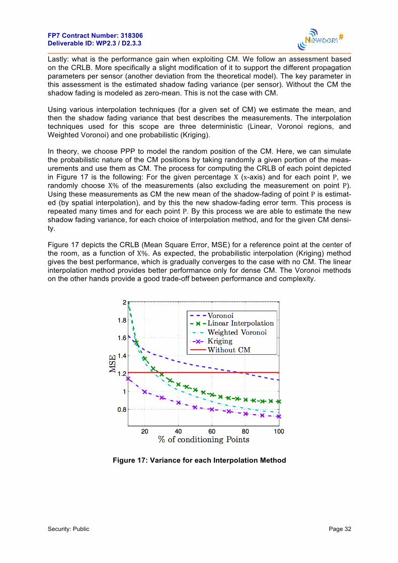
In theory, we choose PPP to model the random position of the CM. Here, we can simulate the probabilistic nature of the CM positions by taking randomly a given portion of the meas-urements and use them as CM. The process for computing the CRLB of each point depicted in Figure 17 is the following: For the given percentage X (x-axis) and for each point P, we randomly choose X% of the measurements (also excluding the measurement on point P). Using these measurements as CM the new mean of the shadow-fading of point P is estimat-ed (by spatial interpolation), and by this the new shadow-fading error term. This process is repeated many times and for each point P. By this process we are able to estimate the new shadow fading variance, for each choice of interpolation method, and for the given CM densi-ty.
Figure 17 depicts the CRLB (Mean Square Error, MSE) for a reference point at the center of the room, as a function of X%. As expected, the probabilistic interpolation (Kriging) method gives the best performance, which is gradually converges to the case with no CM. The linear interpolation method provides better performance only for dense CM. The Voronoi methods on the other hands provide a good trade-off between performance and complexity.
Figure 17: Variance for each Interpolation Method

FP7 Contract Number: 318306 Deliverable ID: WP2.3 / D2.3.3
Security: Public Page 33
Comments and suggestions for the improvement of this document are most welcome and should be sent to:
________________________________________________________________________
http://www.newcom-project.eu