Embed Size (px)
Citation preview

D-TACQ 2G User Guide D-TACQ Solutions Ltd
D-TACQ 2G User Guide
Prepared By: Peter Milne
Date: 01 June 2010.
Date first issue: 7 September 2009
Primary Instruction and Command Reference for D-TACQ Intelligent Data Acquisition Cards:
• ACQ132CPCI
• ACQ196CPCI
• ACQ216CPCI
• WAV232CPCI
• ACQ164CPCI
Comments, corrections and constructive criticism welcome! :
How to read this document:
We do not recommend reading the whole text in detail, it is more of a reference. However for users unfamiliar with the ACQxxx architecture, at least a skim-read of Sections 1-13 is recommended.
It is 140+ pages long : best not to print it.
Recommended way to view: Load in Acroread, use the Bookmarks window for navigation - each section is book marked.
Rev 52 Page 1 of 151 Date: 19 June 2012

D-TACQ 2G User Guide D-TACQ Solutions Ltd
Rev Date Description
1 18 May 04 First issue
2 20 May 04 Work in progress
3 02 Jun 04 Add routing examples
4 23 Jul 04 Add RTMAO16 description
5 23 Jul 04 dio32
6 09 Aug 04 FAWG description
7 20 Aug 04 Data interface description23 January 2008
8 07 Sep 04 Customization via /ffs/rc.local
9 20 Oct 04 Add clock routing scenarios
10 19 Nov 04 Add ssh login descr.
11 24 Feb 05 Routing concept diagram
12 1 March 05 Add to Low Latency section
13 15 March 05 Cal and Vin
14 1 April 05 Ll control updated, RTMDDS
15 10 April 05 Host Pull, Target Push distinction
16 16 May 05 Clarify remote if def.
17 29 July 05 LLCONTROL V2
18 01 Aug 05 Tidy up on LLCONTROL V2
19 02 Aug 05 Improve raw/cooked description.
20 10 Aug 05 Add counter and sundry service changes
21 01 Nov 05 Mean device and friends
22 10 Nov 05 MdsPutCh
23 02 Jan 06 Add rescue section, correct remote.update
24 05 Jan 06 Improve voltage range FAQ
25 09 Feb 06 AO, acq2sh comments.
26 06 May 06 Dt100d operational issues and options
27 13 June 06 Improved Trigger, Event defs
28 18 Sep 06 Calibration file, Channel Block commands
29 20 Sep 06 Improve MDSplus Thin Client coverage
30b 26 Sep 06 Full MDSplus/AO example.
31 01 Nov 06 /etc/postshot.d, calibrate changes
32 03 Jan 07 improve FAWG doc.
33 07 Jan 07 FTP server
34 11 Apr 07 corrected calibration formula
35 03 Aug 07 command sequence FAQ.
36 23 Jan 08 update
Rev 52 Page 2 of 151 Date: 19 June 2012

D-TACQ 2G User Guide D-TACQ Solutions Ltd
Rev Date Description
37 23 May 08 new /ffs structure
38 12 June 08 restored pre_post_mode (thanks Atma!)
40 07 August 08 Repeating Gate Mode, PREPs.
43 08/15/09 ACQ132 document update
44 09/07/09 ACQ132 setExternalClock
45 10/30/09 setExternalClock div detail
46 26/01/10 ACQ132 FIR
47 15/02/10 INTCLK_NOICS, LO_ICS opts for ACQ132CPCI
48 01/06/10 DualRate
49 17/09/10 Document set.acq1xx.role.
50 25/11/10 ACQ164 NACC accumulator.
52 19 June 2012 ACQ196 NACC accumulator.
Rev 52 Page 3 of 151 Date: 19 June 2012

D-TACQ 2G User Guide D-TACQ Solutions Ltd
Table of Contents1 Introduction...............................................................................................................10
1.1 Welcome............................................................................................................101.1.1 Hard real time under Linux.......................................................................10
1.2 Intended Audience............................................................................................111.3 Scope.................................................................................................................111.4 Glossary.............................................................................................................12
1.4.1 Signal Processing Terminology:...............................................................121.4.2 Filter Terminology:....................................................................................121.4.3 Software References..................................................................................131.4.4 References..................................................................................................13
1.5 Notation.............................................................................................................132 Recommended Deployments....................................................................................14
2.1 Standalone Networked......................................................................................142.1.1 Network Topology.....................................................................................14
2.2 Backplane Peripheral Mode..............................................................................142.3 System Slot Controller......................................................................................15
3 Getting Started..........................................................................................................164 Trouble Shooting.......................................................................................................17
4.1 Front Panel LEDs..............................................................................................174.2 Console Interface...............................................................................................17
5 Architecture Overview..............................................................................................185.1 2G Overview.....................................................................................................185.2 Operating Software...........................................................................................185.3 Flash Memory Layout.......................................................................................185.4 Boot sequence...................................................................................................19
6 Personality................................................................................................................206.1 Boot loader........................................................................................................20
6.1.1 IP address..................................................................................................206.1.2 Bootcmd....................................................................................................206.1.3 Rescue........................................................................................................21
6.2 Customization Scripts.......................................................................................216.2.1 Typical /ffs/rc.local.options:.....................................................................22
7 Command and Monitoring Interfaces.......................................................................247.1 CPCI Backplane................................................................................................247.2 Dt100d remote service......................................................................................247.3 Web Service Interface.......................................................................................247.4 Web interface....................................................................................................247.5 Console Interface...............................................................................................257.6 Telnet interface..................................................................................................257.7 Ssh interface......................................................................................................257.8 FTP client..........................................................................................................257.9 FTP server.........................................................................................................267.10 SFTP server.....................................................................................................267.11 SAMBA server................................................................................................267.12 Restrict access to services using TCPwrapper...............................................26
8 Updating Firmware...................................................................................................27
Rev 52 Page 4 of 151 Date: 19 June 2012

D-TACQ 2G User Guide D-TACQ Solutions Ltd
8.1 What Images are involved:...............................................................................278.2 From host computer via ssh..............................................................................278.3 Via CPCI Backplane.........................................................................................278.4 Via Ethernet using nfs.......................................................................................288.5 Via Ethernet using anonymous ftp...................................................................288.6 Via Kermit (serial or Ethernet).........................................................................28
8.6.1 Using kermit via serial port.......................................................................288.6.2 Using kermit via telnet..............................................................................298.6.3 From a website using wget........................................................................29
9 Concepts....................................................................................................................309.1 Clock and Trigger Routing................................................................................309.2 Calibration.........................................................................................................31
9.2.1 Offset Adjust.............................................................................................319.2.2 Gain Adjust................................................................................................319.2.3 Numeric Calibration Procedure.................................................................319.2.4 Calibration Table.......................................................................................339.2.5 Polarity......................................................................................................339.2.6 Full automation example:..........................................................................349.2.7 Calibration Table Example:......................................................................35
10 Command Reference...............................................................................................3610.1 Operating Modes.............................................................................................36
10.1.1 Linear Timebase......................................................................................3610.1.2 Regions of Interest - PRE Programmed triggers....................................3610.1.3 Discontiguous Timebase: Repeating Gate Mode....................................3610.1.4 Random Multiple Events: MULTIVENT...............................................37
10.2 acqcmd Interface: (see ICD)...........................................................................3810.3 dt100 remote interface....................................................................................3810.4 Shell command interface.................................................................................38
10.4.1 High level command Clock Role setting................................................3910.4.2 Signals.....................................................................................................3910.4.3 Generic Pre/Post Mode............................................................................4410.4.4 Repeating Gate Mode..............................................................................4510.4.5 Input Voltage Range................................................................................4610.4.6 Channel Mask and Channel Count..........................................................4710.4.7 Block Technique for Setting Channel Mask...........................................4710.4.8 Access fields in calibration file...............................................................4810.4.9 set.autozero : start an autozero process (Acq196 only)..........................4910.4.10 Analog Output Control..........................................................................5010.4.11 RTM DIO32 Control.............................................................................6010.4.12 Timer Counter........................................................................................6010.4.13 Monitor state with acqstate / statemon................................................62
11 Data Interface: Transient Data...............................................................................6511.1 Introduction.....................................................................................................6511.2 Host Pull vs Target Push.................................................................................6511.3 Post Processing...............................................................................................6611.4 Custom Post-Shot Processing.........................................................................6611.5 Data Devices on target:...................................................................................6711.6 Combing the data............................................................................................67
Rev 52 Page 5 of 151 Date: 19 June 2012

D-TACQ 2G User Guide D-TACQ Solutions Ltd
11.7 Efficient Comb Read With readd...................................................................6811.8 MDSplus Thin Client......................................................................................69
11.8.1 Mdsshell detail:.......................................................................................6911.8.2 mdsPut special features...........................................................................7011.8.3 mdsPutCh - device-aware upload...........................................................7111.8.4 mdsValue - retrieve and store values......................................................74
11.9 MDSplus Thick Client....................................................................................7611.10 Rolling mean Channel data available during shot........................................7611.11 Rolling mean Cross-section data available during shot...............................7611.12 Logical to Memory Channel mapping table.................................................7711.13 Host Pull Examples.......................................................................................78
11.13.1 Access from host computer via PCI bus...............................................7811.13.2 Remote access via dt100d.....................................................................7811.13.3 Remote access via dt100-hub................................................................7811.13.4 Remote access via networked file system............................................7811.13.5 http GET................................................................................................78
11.14 Target Push Examples...................................................................................7911.14.1 MDSplus thin client..............................................................................7911.14.2 FTP client..............................................................................................8011.14.3 Remotely specify an ftp batch job........................................................80
12 Data Interface: Continuous Streaming...................................................................8212.1 Introduction.....................................................................................................8212.2 Ethernet: Host-Pull Streaming........................................................................8212.3 Ethernet: Target-Push Streaming....................................................................8212.4 CPCI Backplane: Target-Push Streaming......................................................8312.5 Cabled PCI-Express: Target-Push Streaming................................................83
13 Putting it all together – Use Cases.........................................................................8413.1 Chassis clock master uses local derived clock...............................................8413.2 Chassis Master uses plant clock, distributes derived clock...........................8513.3 Slave Derives Clock from Backplane.............................................................8613.4 Slave Uses Backplane Clock Directly............................................................8713.5 Internal Clock, optional backplane Clock Master..........................................8813.6 ACQ216 Precision Internal Clock using RTM-DDS.....................................8913.7 ACQ216 Internal Clock Multiplier ................................................................9013.8 External Clock with precision RTM-DDS multiplier....................................91
14 Appendix: PREPs - Regions of Interest.................................................................9314.1 Preprogrammed Triggers ...............................................................................93
14.1.1 Example 1: "Dark Calibration"...............................................................9314.1.2 Example 2: Event as Trip. ......................................................................93
14.2 Mechanism......................................................................................................9314.2.1 Overview.................................................................................................9314.2.2 Enabling preps.........................................................................................9414.2.3 Operational issues...................................................................................9414.2.4 Device Nodes:..........................................................................................9514.2.5 Specification............................................................................................9514.2.6 Run Time Status polling..........................................................................9514.2.7 Summary..................................................................................................9614.2.8 Data Handling.........................................................................................96
Rev 52 Page 6 of 151 Date: 19 June 2012

D-TACQ 2G User Guide D-TACQ Solutions Ltd
14.2.9 Recommendation for immediately handling PREP data........................9614.2.10 How does acton_prep run......................................................................9714.2.11 Channelized Data..................................................................................97
15 Appendix: D-TACQ Low Latency Mode..............................................................9915.1 Notes on achieving Hard Real Time performance.........................................9915.2 LLC Module..................................................................................................10015.3 Signals...........................................................................................................10115.4 Typical Plant Operating Scenario.................................................................10215.5 Bus Level Protocol........................................................................................10215.6 Description of Operation...............................................................................10415.7 LLCONTROL Host side application............................................................10415.8 Setup for Low Latency control.....................................................................10415.9 Digital IO......................................................................................................10615.10 Host Side Driver Capability.......................................................................10715.11 LLCONTROL V2 Performance Enhancement:..........................................108
15.11.1 Feature Set...........................................................................................10815.11.2 Programming Interface........................................................................10915.11.3 SYNC_2V combined IO vectors minimize latency............................11215.11.4 SYNC_2V_AO32 ...............................................................................11215.11.5 SYNC_2V_RFM.................................................................................112
16 Appendix: Low Latency mode on ACQ216.........................................................11316.1 Initialisation:.................................................................................................11316.2 Operation:......................................................................................................113
17 Appendix: RTM-DDS...........................................................................................11517.1 Clock Source.................................................................................................11617.2 Output Routing..............................................................................................11617.3 Control signal direction in relation to front-side board...............................11617.4 Operational Considerations for DDS............................................................116
18 Appendix: Linux Tips...........................................................................................11718.1 Dt100-hub configuration...............................................................................11718.2 Port forward remote satellite........................................................................11718.3 Hook to services via lsa................................................................................11718.4 Access MDSplus via shell scripts on x86 host.............................................118
18.4.1 Submitting continuous framed data to MDSplus.................................11818.4.2 Extracting data from MDSplus to export to analysis...........................118
19 Appendix: FAQ.....................................................................................................11919.1 What is the Voltage Encoding?....................................................................11919.2 How to run custom inetd services.................................................................12019.3 When do you use acqcmd -b, acqcmd -s, acq2sh?.......................................120
19.3.1 Summary of acqcmd/shell usage...........................................................12119.4 Why doesn't my command line argument work?.........................................12119.5 How do I set up public key login..................................................................122
19.5.1 First check if you already have a public key set up:............................12219.5.2 Create host public keys.........................................................................12219.5.3 Copy the keys to the target....................................................................12219.5.4 Check it Works......................................................................................12219.5.5 Save the keys to non-volatile disk system............................................122
19.6 Trigger, Event – What, Why, When?...........................................................123
Rev 52 Page 7 of 151 Date: 19 June 2012

D-TACQ 2G User Guide D-TACQ Solutions Ltd
19.6.1 What:.....................................................................................................12319.6.2 Why.......................................................................................................12319.6.3 When......................................................................................................123
19.7 What sequence must commands be issued in?.............................................12419.8 What is the sample phase when using derived clock?..................................124
20 Appendix: ICD changes for 2G............................................................................12520.1 Remote Commands (replaces ICD 4.10.1)...................................................125
20.1.1 Overview...............................................................................................12520.1.2 Command Summary..............................................................................12620.1.3 Dt100d operational considerations.......................................................131
20.2 acqcmd command synopsis..........................................................................13221 Appendix: acq200.pp Postprocess Script.............................................................13322 Appendix: ACQ216CPCI Add-ons......................................................................134
22.1 RTMDDS......................................................................................................13422.2 FPGA Personality.........................................................................................135
23 Appendix: ACQ132CPCI Add-ons......................................................................13623.1 Valid Channel Masks....................................................................................13623.2 CLOCK.........................................................................................................138
23.2.1 Oversampling: Decimate/Accumulate..................................................13823.2.2 Internal Clock........................................................................................13823.2.3 External Clock.......................................................................................13923.2.4 Clock Diagnostic...................................................................................140
23.3 ACQ132-32-65G: High Speed Transients RGM..........................................14223.3.1 Timebase................................................................................................142
23.4 GPG Gate Pulse Generator...........................................................................14323.4.1 Low Level Interface:.............................................................................14323.4.2 High Level Interface..............................................................................144
23.5 Multi-Rate Capability...................................................................................14523.5.1 Restrictions:...........................................................................................146
23.6 Switched DualRateMode..............................................................................14623.6.1 Example:................................................................................................146
23.7 Oversampling FIR Filter...............................................................................14823.7.1 Available Personalities..........................................................................14823.7.2 Select.Personality..................................................................................149
24 ACQ164CPCI Special Characteristics.................................................................15024.1 Accumulate/Decimate function....................................................................150
25 ACQ196CPCI Special Features............................................................................15125.1 Pulse Generator.............................................................................................15125.2 Final Stage Filter: Accumulate/Decimate function......................................151
25.2.1 Examples:..............................................................................................151
Rev 52 Page 8 of 151 Date: 19 June 2012

D-TACQ 2G User Guide D-TACQ Solutions Ltd
Copyright and Attribution.Document created using OpenOffice.Org www.openoffice.org.
This document and D-TACQ Software comprising platform Linux port, Linux kernel modules and most applications are released under GNU GPL/FDL:
Document:
Copyright (c) 2004-10 Peter Milne, D-TACQ Solutions Ltd.
Permission is granted to copy, distribute and/or modify this document under the terms of the GNU Free Documentation License, Version 1.2, with no Invariant Sections, no Front-Cover Texts, and no Back-Cover Texts.
Software:
Copyright (C) 2004-10 Peter Milne, D-TACQ Solutions Ltd.
This program is free software; you can redistribute it and/or modify it under the terms of the GNU General Public License version 2 as published by the Free Software Foundation.
This program is distributed in the hope that it will be useful, but WITHOUT ANY WARRANTY; without even the implied warranty of MERCHANTABILITY or FITNESS FOR A PARTICULAR PURPOSE. See the GNU General Public License for more details.
You should have received a copy of the GNU General Public License along with this program; if not, write to the Free Software Foundation, Inc., 59 Temple Place, Suite 330, Boston, MA 02111-1307 USA
Rev 52 Page 9 of 151 Date: 19 June 2012

D-TACQ 2G User Guide D-TACQ Solutions Ltd
1 Introduction
1.1 Welcome
The D-TACQ second generation (2G) series is a revolutionary concept in Data Acquisition. We take the D-TACQ simultaneous ADC array, combined with a high bandwidth FPGA data path to fast DDR memory. This is managed by an on-board microprocessor – a 400MIPS ARM device; an embedded system running an advanced operating system. Not some specialist system, but Linux. Using Linux means that there is a familiar environment with excellent connectivity and data management facilities built in, and the system may be customized and extended using simple shell scripts and or by writing higher level applications in the familiar memory protected POSIX environment.
D-TACQ believes this is an ideal platform for High Performance Simultaneous Data Acquisition.
1.1.1 Hard real time under Linux.
How do we expect true real time performance from Linux? The answer is, we don't. D-TACQ 2G has one critical interrupt, related to the acquisition FIFO. This is handled by the ARM FIQ interrupt; the FIQ operates outside the control of Linux and is never masked. The job of the FIQ is to arm the on-board DMAC and to detect external events; driver code under Linux has the responsibility of maintaining queues of empty DMA descriptors going to the FIQ and dequeuing full DMA descriptors coming back from the DMAC. Provided the queues are long compared with the maximum Linux task latency (and they are), Linux has sufficient real time capability for this task.
Please note that 2G is an exceedingly high bandwidth system (500 MBytes/sec sustained transfer to memory on ACQ216CPCI). When operating at full speed, the FIQ/DMA operation will occupy most of the available CPU resources and so the system will become unresponsive to application input. Applications requiring significant real time data processing are best handled in the FPGA .
In addition, it is possible to extend the capability of 2G using kernel modules; typically the kernel modules will disable interrupts altogether during capture and take complete control of microprocessor execution. An example of this is the Low Latency Control module.
Rev 52 Page 10 of 151 Date: 19 June 2012

D-TACQ 2G User Guide D-TACQ Solutions Ltd
1.2 Intended Audience
Users of D-TACQ 2G products, software developers integrating the products with existing data management systems, and software developers developing applications to enhance the product.
1.3 Scope
This guide is generic to all 2G products. Where products vary in detail, examples are provided for each.
Current applicable products are:
• ACQ196CPCI
• ACQ216CPCI
• ACQ132CPCI
• ACQ164CPCI
• WAV232CPCI
Functionality specific to each of these products is handled in a separate appendix.
Rev 52 Page 11 of 151 Date: 19 June 2012

D-TACQ 2G User Guide D-TACQ Solutions Ltd
1.4 Glossary
ACQxxx : generic reference to D-TACQ 2G card eg ACQ196CPCI, ACQ216CPCI
ADC: Analog to Digital Converter.
ARM: Advanced RISC Machine – a microprocessor architecture.
CompactPCI : industrial formfacto with Eurocard mechanics, PCI signaling
XSCALE: Intel implementation of the ARM architecture, used on D-TACQ 2G.
D-TACQ: D-TACQ Solutions Ltd.
DDR: Double Data Rate (double edged clocking memory standard).
DMA: Direct Memory Access, DMAC: DMA Controller.
ES: Event Signature - a marker inserted in the data stream at the point of an external event occurrence.
FIQ: ARM architecture Fast Interrupt.
FPGA: Field Programmable Gate Array.
PCI: Commonly used computer bus.
PLL: Phase Locked Loop
POSIX: Portable Operating System based on Unix (Unix API).
PS_CLK: Plant System CLK (typically at front panel)
SCLK: Sample Clock (to ADC)
ROI: Region Of Interest
RTM: Rear Transition Module.
RTOS : Real Time Operating System.
TARGET: in this context, an ACQxxx acquisition card, either connected via PCI backplane or Ethernet.
HOST: A computer that provides support for TARGET. Usually an x86 Linux computer, may connect either via PCI backplane or by Ethernet.
diskless : computer running with no local hard disk.
1.4.1 Signal Processing Terminology:
SNR: Signal to Noise Ratio
1.4.2 Filter Terminology:
AAF: Anti-Alias Filter (analog).
FIR: Finite Impulse Response (digital) filter
ISR: Input Sample Rate
OSR: Output Sample Rate
Rev 52 Page 12 of 151 Date: 19 June 2012

D-TACQ 2G User Guide D-TACQ Solutions Ltd
PASSBAND: Passband of the filter (3dB), frequency where roll-off starts.
STOPBAND: Stopband of the filter - frequency where maximum attenuation is obtained.
1.4.3 Software References
dt100rc : D-TACQ supplied HOST client reference program and GUI
acq_demux : D-TACQ API example program.
streamer: D-TACQ API example program.
kst: Open Source plot program suitable for large binary data sets
DirFile : simple binary file format
ftp : (Internet) File Transfer Protocol
1.4.4 References
1. Interface Control Document ICD : this is the primary command reference, and is unchanged from the 1G product range, except where overridden by new commands (see 20.1)
2. ACQxxx Hardware Installation Guide3. D-TACQ Network Attached Satellite Data Acquisition (dtNasDaq.pdf)4. SoftwareInstallationGuideR35. Intel 80321 IO Processor Developer's Manual (273517-002)
1.5 Notation
• command : indicates name of a program (command)
• preformatted text : literal input or output from terminal session.
• Defined Term : some term or acronym specific to this domain (perhaps referenced in the glossary)
Rev 52 Page 13 of 151 Date: 19 June 2012

D-TACQ 2G User Guide D-TACQ Solutions Ltd
2 Recommended Deployments
2.1 Standalone Networked
ACQxxx devices are capable, where fitted with Ethernet, of operating as diskless satellite units. This is outlined in [3].
The satellite may be controlled:
• Directly via applications using the dt100 Remote Network Protocol as described in (ICD). D-TACQ supplies dt100rc as an example of such and application.
• indirectly via a dt100-hub middle layer server, allowing existing support software to run with the minimum change. Dt100 Networked Attached Satellite DAQ mode.
• Directly from the Linux shell on the box – the familiar acqcmd protocol is available on the box; it is feasible directly automate a local telnet shell session from a remote machine (e.g. using expect). Or it is possible to write a local server application (e.g. mdsip); this exercise would involve porting to the embedded ARM-LINUX environment.
• It is possible to write a local control process. Examples of this is the autozero and calibrate processes.
2.1.1 Network Topology
When operating on the Ethernet, best performance will be achieved if a dedicated “field bus” Ethernet can be deployed between the middle layer machine and the ACQxxx. This is not only for reasons of performance, but security as well:
• controlled link means maximum network bandwidth available for data upload.
• Controlled link mean that the embedded network interface is not exposed to uncontrolled incoming packet activity during the critical real time capture phase. The capture process has to handle real time data flows of up to 320MB/sec, and it has to check for remote abort packets on the network interface, so it is not possible to simply ignore network packets. If the acquisition card is connected direct to the global Ethernet, it is highly likely that it will be exposed to random, unrepeatable bursts of network activity – maybe not even addressed to it, that could cause hard to trace failures.
2.2 Backplane Peripheral Mode
ACQxxx cards by default act as CompactPCI PCI peripheral devices. The full speed 64 bit, 66MHz interface is supported, and so the ACQxxx will work with what ever speed and bus width is selected by the system slot card.
ACQxxx has a full master/slave interface, and, for maximum performance will
Rev 52 Page 14 of 151 Date: 19 June 2012

D-TACQ 2G User Guide D-TACQ Solutions Ltd
master data on the bus.
For installation instructions for Host side driver for this mode, please refer to [4]
2.3 System Slot Controller
By factory configuration option, ACQxxx cards are able to perform the system slot function for other cards in the CompactPCI chassis. In addition, ACQ196 has a jumper option for “Standalone Mode” where the card isolates itself from the
backplane PCI logic.
Rev 52 Page 15 of 151 Date: 19 June 2012
J1
J2
J3
J5
J4
Rear Tran s it ion m od uleTMAO
100BaseTEth RJ45
32 DIO/68W SCSI2
16 AO/68W SCSI2
32 AIon 68W SCSI2
32 AIon 68W SCSI2
32 AIon 68W SCSI2
EXT CLK, TRIG on LEMO
JP10:IN: Stand alon eOUT: PCI
JP11:IN: Defau ltOUT: Jtag – n ot for custom er use.

D-TACQ 2G User Guide D-TACQ Solutions Ltd
3 Getting Started1. Mechanical installation: refer to “Installation Guide”. Currently it is mandatory
that each front side board have an accompanying RTM at the rear side.
WARNING: Please ensure compatible RTM:
ACQxxx must only be used with an ACQxxx RTM
ACQxxx must only be used with an ACQxxx RTM
Quick Check: ACQxxx RTM has twin RJ45 for dual Ethernet, ACQ196 RTM has single RJ-45
2. Jumpers: There is one user jumper on ACQ196CPCI: JP10. For standalone applications, JP10 should be fitted, for system slot and peripheral mode operation it should be removed. There are no user jumpers on ACQ216CPCI.
3. Console. Connect to console port to check configuration of firmware. Requires 9Way D null-modem cable and a terminal emulator. D-TACQ uses and recommends kermit (http ://www.columbia.edu/kermit/ ). Terminal emulator should be set to 38400 baud, 8bit, [one stop] no parity.
4. Power up and confirm boot up through to Linux prompt. There is no longer any need to modify boot parameters in normal operation. If it doesn't appear to boot, please refer to “Trouble Shooting” in next section.
5. For standalone operation, make an Ethernet. connection to the RJ45 socket on the RTM. It is recommended that this connection be part of a data-acquisition-private network. A full duplex switched connection will work best, for ACQ196 a dedicated cross-over cable to a dedicated client NIC is also a valid option. Default IP address settings are obtained by DHCP. Alternatively a static IP address may be configured by editing a boot script. (#6.2 )
6. Check the system boots normally. If the console is connected, you will see boot prompts, if the front panel LEDs are visible, you will see the lamp sequence, as described in 4.1.
7. D-TACQ recommends use of the point and click dt100rc remote control program for initial testing. For serious volume data management and storage, D-TACQ recommends MDSplus (www.mdsplus.org). MDSplus control is provided via either the dt100-hub network interface, or via backplane drivers. MDSplus support is also available on the card, allowing automated submit of post-shot capture data direct to an MDSIP server.
8. Refer to the embedded web pages for diagnostics and status. The web pages are presented at port 80. D-TACQ recommends firefox or mozilla rev 1.5 or better for best viewing effect.
Rev 52 Page 16 of 151 Date: 19 June 2012

D-TACQ 2G User Guide D-TACQ Solutions Ltd
4 Trouble Shooting
4.1 Front Panel LEDs1. On reset, all LEDs are out.
2. On release of reset, the boot loader lights all 4 LEDs (lamp test)
3. The lamp test remains in effect during LINUX boot up (about 1 minute).
4. When Linux is running, LEDs 3 and 4 are extinguished. LED2 (RED) will flash at about a 1Hz rate. LED1 (GREEN) indicates CPU idle – in normal rest state, this is one, and then will flash according to CPU activity.
4.2 Console Interface.
The RS232 console interface is provides the next level of access for customization and debug. Configuration of the boot loader is as described in #6.1.
Rev 52 Page 17 of 151 Date: 19 June 2012

D-TACQ 2G User Guide D-TACQ Solutions Ltd
5 Architecture Overview
5.1 2G Overview
The D-TACQ 2G architecture comprises :
• Analog front end array, one converter device per channel for simultaneous capture.
• Fast data path to control FPGA.
• Internal logic for data marshaling, trigger detection and clocking in the FPGA.
• Internal FIFO buffers in the FPGA
• Fast local bus to microprocessor
• High performance, low power microprocessor (400MHz, XSCALE/ARM arch)
• Very high speed 200MHz DDR bus to local memory
• 64bit/66MHz PCI interface to backplane.
• Optional Ethernet interface (2 x 1000baseT on ACQ216, 1x 1000baseT on ACQ132/ACQ164, 1x100baseT on ACQ196).
• The system is fully firmware controlled – both operating microprocessor and FPGA firmware images are stored in flash memory and may be upgraded in system without difficulty.
5.2 Operating Software
The local microprocessor runs Linux. This is a full virtual memory implementation, 2.6.x series. All kernel source code is available under GPL. The Linux system is stored in flash memory as a compressed kernel image. Initial and additional compressed file system images are held in flash memory, and expanded into a local ram disk at run time. The ram disk is self sizing, but is typically 20MB. An additional flash sector is formatted as JFFS2 to allow non-volatile disk storage, e.g. for calibration data and local customization. Finally, the FPGA image is stored in a dedicated sector. It is possible that alternative FPGA images may be stored in the file system images.
5.3 Flash Memory Layout f0000000-f001ffff : /dev/mtd0 Bootldr f0020000-f003ffff : /dev/mtd1 Env f0040000-f01bffff : /dev/mtd2 SafeKrn f01c0000-f01fffff : /dev/mtd3 FPGA f0200000-f03fffff : /dev/mtd4 SafeRd f0400000-f05fffff : /dev/mtd5 FieldKrn f0600000-f07fffff : /dev/mtd6 FieldRd f0000000-f0bbffff : /dev/mtd7 extra f0bc0000-f0f3ffff : /dev/mtd8 home f0f40000-f0ffffff : /dev/mtd9 cal
Rev 52 Page 18 of 151 Date: 19 June 2012

D-TACQ 2G User Guide D-TACQ Solutions Ltd
• mtd0, mtd1: Boot loader partitions: writable by u-boot only• mtd2..mtd7: compressed images held in flash, Linux updateable.• mtd8, mtd9: jffs2 flash file systems, for non-volatile customizations.
5.4 Boot sequence.
Boot loader U-Boot
bootm <vmlinux.img> <initrd.img>
Linux kernel boot up.
Mounts initrd as a ram disk, runs:
init
runs:
/etc/init.d/rc.sysinit
configures local ram disk file system
starts networking
sets hostname and installs core devices
calls
/acq200/start.local
expands file system image in mtd7 and mounts as ram disk at /extra
calls
/usr/local/bin/start.local MACHINE
more initialisation based on extra disk.
calls start.MACHINE
Mounts mtd9 as /ffs
runs /ffs/cal/autozero if it exists
runs /ffs/rc.local if it exists.
gets options from /ffs/rc.local.options
runs /ffs/user/rc.user if it exists
Rev 52 Page 19 of 151 Date: 19 June 2012

D-TACQ 2G User Guide D-TACQ Solutions Ltd
6 Personality
Please Note: Boot loader setup is now for expert users only.
Initial setup (notably static IP address) is now achieved via custom boot script
/ffs/user/rc.user (Section6.2)
6.1 Boot loader
The boot loader is U-Boot (www.u-boot.org), and the boot loader interface is via the console port.
By default, the boot loader will attempt to auto boot Linux.
To break into the boot loader, press space bar within 3 seconds.
U-Boot is configured by means of boot parameters.
A typical setup is as follows:
setenv bootdelay 3setenv baudrate 38400setenv ramdisk ramdisk_size=16384 root=/dev/ram0setenv console console=ttyS0,38400setenv hn hostname=acq196_001setenv ba acq100=acq196setenv bootcmd bootm a0400000 a0600000setenv mac gEmac0=10:01setenv sn serialnum=d30001setenv ipa ip0=dhcpsetenv boota $console $ramdisk $hn $sn $macsetenv bootargs $boota $ipa $basetenv bootcmd bootm a0400000 a0600000saveenv
6.1.1 IP address
Default is to use dhcp. Alternately a static IP address may be set as follows:
setenv ipS ip0=192.168.0.1setenv bootargs $boota $ipS $ba
saveenv
Please note: this is superseded by Linux boot script /ffs/rc.local (# 6.2 )
6.1.2 Bootcmd
The actual kernel and ramdisk images to be booted are specified as:
Rev 52 Page 20 of 151 Date: 19 June 2012

D-TACQ 2G User Guide D-TACQ Solutions Ltd
setenv bootcmd bootm a0400000 a0600000
6.1.3 Rescue
In the event that the default “field” images do not work, there is the possibility to fall back on stored “safe” images in order to boot safely, and reprogram the “field” images:
setenv bootcmd bootm a0040000 a0200000boot
It is not necessary to save this command to flash – it is preferred to boot right away, repair the images, and on the next boot, U-Boot will default back to the field images and run them.
6.2 Customization Scripts
The non-volatile flash file system allows storage of system personality and customisation.
Two flash file system partitions are implemented:
1. /dev/mtd9 mapped as /ffs : 768K : custom boot, personality, patches
2. /dev/mtd8 mapped as /bigffs: 3584K : additional software eg EPICS image
Board specific personality can be added in /ffs/user/rc.user
A number of boot time options may be selected in /ffs/rc.local.options
These files may be edited locally in place.
A common requirement is to select a static IP address, and a command is provided for this:
/sbin/set.static_ip
example: to set a static IP address 192.168.111.222:
/sbin/set.static_ip IP0 192.168.111.222
In general, /ffs/rc.local should NOT be edited, changes will not be preserved through firmware updates. User customization should be made in /ffs/user/rc.user. The following directories are preserved through firmware update:
/ffs/cal /ffs/user /ffs/dropbear
/ffs/rc.local.options is backed up to /ffs/rc.local.options.orig
/bigffs is not touched by normal firmware update.
Rev 52 Page 21 of 151 Date: 19 June 2012

D-TACQ 2G User Guide D-TACQ Solutions Ltd
6.2.1 Typical /ffs/rc.local.options:
#!/bin/sh # local configuration options for rc.local # set static IP address from local file ONLY IF the file exists #IP0=192.168.0.123 #IP1=0.0.0.0 # remote logging #RLOG=YES #RLOGHOST=192.168.0.1 # telnet, http enabled by default, uncomment to disable #DISABLE_TELNET=YES #DISABLE_HTTPD=YES # usually a good idea to run this SSHD=YES # Clock Trigger Role - preset Clock Trigger behaviour # choose one or none # uncomment one of the following lines to configure clock and trigger routing # NB: only ONE master device per chassis!! #CT_ROLE=LEMO_MASTER ;# lemo in drives fpga and PXI - flashes LED4 for LEMO ID #CT_ROLE=PXI_SLAVE ;# fpga driven from PXI #CT_ROLE=FPGA_MASTER ;# fpga drives PXI for looptest - LED4 solid
# MDSplus thin client - stub it out if not needed #MDSSHELL=YES
# mean device - subrate data during pre/post #MEAN_DEV=YES # EPICS - enable if needed. NB needs special EPICS image in /bigffs #EPICS=YES # For ACQ216CPCI-M5-RTMDDS: #M5=YES #RTMDDS=YES # Live scope demo #SCOPE_DEMO=YES # for low-latency control mode (LLC) uncomment next line #LLC=YES # use this to activate DIO32 support. ONLY IF RTM WITH DIO32 IS FITTED #DIO32=YES # NTP client, and ntp host for client #NTP=YES #NTPCLIENT=192.168.0.1 # external state monitor service #STATED=YES # ftp daemon #FTPD=YES # watchdog timer #WDT=YES # remote access to AO fungen or voltage source #FGD=YES
Rev 52 Page 22 of 151 Date: 19 June 2012

D-TACQ 2G User Guide D-TACQ Solutions Ltd
#VSD=YES
Rev 52 Page 23 of 151 Date: 19 June 2012

D-TACQ 2G User Guide D-TACQ Solutions Ltd
7 Command and Monitoring Interfaces
7.1 CPCI Backplane
Standard acqcmd device interface by memory resident device driver.
Also offers extend able remote-shell interface.
7.2 Dt100d remote service
Operates on Ethernet, listening at port 53504.
Implements dt100 remote protocol (see ICD).
Compatible with dt100rc and dt100-hub.
The latter is a host side Linux driver, combined with a proxy server, emulates the backplane device interface. Instructions for use of dt100-hub are to be found in the README file for the dt100-hub source code package.
7.3 Web Service Interface
ACQxxx offers an remote RPC service based on SOAP.
The cards feature an embedded service built around the excellent gSOAP product.
At the lowest level, the standard acq2sh/acqcmd interface is offered.
Example cross platform remote client applications are provided running on both Linux and Windows. Binary executables and source code are provided for C++ remote clients. A VB.NET example is also provided.
A high level API is also offered, currently this is only available to remote clients coded in C++ and linked to gSOAP.
A full overview of the SOAP interface is available at:
http://www.d-tacq.com/details_page.php?prod_id=applications&page_id=2
The interface is documented at:
http://www.d-tacq.com/resources/SOAPI/html/index.html
7.4 Web interface
Web server based on thttp operates at port 80.
A series of cgi screens for monitoring and test are available at: /cgi-bin/home.cgi.
Please note: The Web interface is not intended as a production tool, since the setups generated are neither automated not persistent. The value of the Web interface is quick access to control parameters, allowing easy manual setup of tests.
D-TACQ recommends that users use the Web interface for initial setup. Once a
Rev 52 Page 24 of 151 Date: 19 June 2012

D-TACQ 2G User Guide D-TACQ Solutions Ltd
working scenario is achieved, to record and possibly script the same command sequence, consult the web log (with target based event log, logread, or, if using remote syslog facility, review the host syslog – usually /var/log/messages on Linux hosts).
A number of the web pages make use of JavaScript. This is tested to work on FireFox and Konqueror . Some of the pages may fail to work correctly under IE.
7.5 Console Interface
Occasional access to the local serial port console via RS232 is required.
D-TACQ recommends kermit to connect to the console, but any terminal emulation program will work (examples include minicom, hyperterm). 38400, 8np.
The console port is the only place where root login is available.
7.6 Telnet interface.
Telnet service is available at port 23. Login as user dt100. root login is disabled.
While this service is still enabled by default, D-TACQ recommends use of ssh:
7.7 Ssh interface.
Regular ssh service available at port 22. D-TACQ encourages use of this interface for remote log in and remote command execution. Login via public key exchange works well and is highly recommended, it is particularly useful when used with remote update.
Public keys are stored on the target in:
/ffs/dropbear/root/.ssh/authorized_keys
/ffs/dropbear/home/dt100/.ssh/authorized_keys
New keys should be appended to the file, then reboot the target to activate. The system ships with default d-tacq public keys, please leave them in place if you want to allow us in-system maintenance access.
The ssh interface also provides a useful runtime path copy utility – any files in /ffs/dropbear are copied to their corresponding locations in the root fs at boot time.
7.8 FTP client
A full ftp client implementation is supported. This can be used for automated “Target Push” upload post capture.
It is recommended that ftp is used with a .netrc file. Store a non volatile copy of your .netrc file in /ffs/dropbear/root and it will be updated to the rootfs at boot time.
Rev 52 Page 25 of 151 Date: 19 June 2012

D-TACQ 2G User Guide D-TACQ Solutions Ltd
7.9 FTP server
A full ftp server implementation is available onboard. For security this is disabled by default. The ftp server may be started as required or from /ffs/rc.local.
• /sbin/start.ftp : starts ftp server, works with dt100 and ftp (anonymous) logins
• /usr/local/bin/start.acq196.ftp : starts ftp server, as above, plus:
• user ai : password free login gives access to AI data
• user ao: password free login gives access to AO data.
• For security, it's not possible to login as root.
• The ftp server will not work with data sets > 6MB.
7.10 SFTP server
An sftp server is also available. This is file transfer over ssh. It's secure, but quite slow. So it is good for transferring setup data, but is not recommended for capture data.
7.11 SAMBA server
A SAMBA server is available, allowing direct export of captured data as an MS-Windows compatible network file share. This interface has good performance.
7.12 Restrict access to services using TCPwrapper.
The standard inetd implementation can be replaced by TCPwrapper, so that access to services may be controlled by ACL's.
Rev 52 Page 26 of 151 Date: 19 June 2012

D-TACQ 2G User Guide D-TACQ Solutions Ltd
8 Updating FirmwareACQxxx cards ship with the latest firmware. However to take advantage of bug fixes and enhancements after delivery, it may be necessary to perform a firmware update.
Please note, in a correctly configured system, firmware upgrade is a routine procedure. However, it is not foolproof, so please monitor the upgrade process looking for error messages. If you do see errors, it may save you time not to reboot until the errors are resolved. The ACQxxx card does have a failsafe boot image which can be used if the firmware upgrade fails. [6.1.3]
8.1 What Images are involved:
Item File Name Description Fmt Frequency
of Update
Scope
1 vmlinux.img Linux kernel uboot 1 common2 initrd.boot Initial ramdisk uboot 1 common3 Extra.img Application ramdisk gz 3 common4 AcqXXX.rbt FPGA firmware gz 2 model5 xxx.gz Custom application gz 2 common
Frequency 1 = seldom, 2 = more frequent, 3 = most frequent.
Images 1,2,3 are common to all ACQxxx, ACQxxx.
Image 4 is specific to the board model, and indeed to the FPGA device fitted on the board. Please contact D-TACQ for update advice.
Several Custom application images are available -
eg MDSplus Thick Client, EPICS IOC.
8.2 From host computer via ssh
This works well if you have public key login set up.
On the host:
In release top level directory:
./images/remote.update <ip> <hostname> [opts]
opts :: [vmlinux] [initrd][extra] [cal] [fpga] [allbutcal] [all]
This procedure works natively on a Linux computer, but has also been tested from Windows using cygwin.
8.3 Via CPCI Backplane
On slot 1 host (assumed x86 Linux), using upgrade.all.acq200.
Rev 52 Page 27 of 151 Date: 19 June 2012

D-TACQ 2G User Guide D-TACQ Solutions Ltd
Please note that upgrade.all.acq200 will upgrade all boards unless boards are specified by number on the command line. The actual make up of the configured images is determined by a data file (def.def). Currently upgrade.all.acq200 is unable to discriminate between target types, and in a mixed target system, it is recommended to to set def.def to suit each board individually, and to upgrade one board at a time. def.def is generally a soft link to a device specific file eg acq196.def.
cd images; ./upgrade.all.acq200 [b1 ... bn]
8.4 Via Ethernet using nfs
While this uses the fast Ethernet path to transfer data, however, it is necessary to login as root to do this.
nfsmount host:/exports ;# mounts remote disk to /mnteflash [all | vmlinux | initrd | extra | cal | fpga]
8.5 Via Ethernet using anonymous ftpPrerequisite: embedded ftp server has been started. [7.9]
Log in as root (console or ssh).
Ftp to the card as user "ftp" (no password).
For each image, upload via ftp, then, from the login session, run:
fflash [image]
8.6 Via Kermit (serial or Ethernet)
Kermit is available in the on board disk and is useful for file transfer when the above methods are not available. This possibility exists not only for the serial console interface, but also for the network interface. The latter is particularly useful with dt100-hub and port forwarding. (See [3]).
8.6.1 Using kermit via serial port.
This is slow – only use this method if Ethernet and PCI methods are unavailable.
1. Connect console interface in the normal way from a remote kermit session
2. kermit -x starts acqXXX-local server
3. Type kermit esc (CTRL-\) to drop back to local client
4. Type send local-file remote file
5. Type fin to exit local server
6. Type c to connect to ACQxxx
7. kflash [all | vmlinux | initrd | extra | cal | fpga]
Rev 52 Page 28 of 151 Date: 19 June 2012
D-TACQ 2G User Guide D-TACQ Solutions Ltd
8.6.2 Using kermit via telnet
Same as before but much faster. All steps other than Connect are the same:
1. Connect using
KERMIT> set telnet wait-for-negotiations offKERMIT> telnet ACQxxx
2. repeat as above.
8.6.3 From a website using wget
A useful emergency procedure – place the firmware images on a local webserver.
Log in to the target (perhaps from the serial console), cd /tmp, use wget to fetch the images, program with kflash.
Rev 52 Page 29 of 151 Date: 19 June 2012

D-TACQ 2G User Guide D-TACQ Solutions Ltd
9 Concepts
9.1 Clock and Trigger Routing
Rev 52 Page 30 of 151 Date: 19 June 2012

D-TACQ 2G User Guide D-TACQ Solutions Ltd
set.route is described in more detail below, acqcmd setDIO is as described in the ICD.
9.2 Calibration
9.2.1 Offset Adjust
Where an effective hardware zero offset adjust mechanism is available, cards are supplied with a zero offset calibration that will be set up at boot. The cards may be recalibrated at any time using autozero Error: Reference source notfoundError: Reference source not found.
Cards with this feature include ACQ196CPCI.
9.2.2 Gain Adjust
D-TACQ cards are NOT provided with a hardware gain adjustment, however an effective gain adjustment may be made by use of the calibration table:
9.2.3 Numeric Calibration Procedure
D-TACQ cards are provided with a calibration sequence. The calibration is used to adjust the values returned by the per-channel range report get.vin. 10.4.5.
The embedded system does not attempt to make any floating point data adjustment on the raw data, but stores the calibrated value in a table for use by external clients. The higher powered remote archival computers can make an accurate conversion from raw data to volts as required.
This sequence should be run if improved calibration is required, after any hardware offset adjust has been applied.
Computing the calibrated voltage is a matter of applying the straight line formula:
y−Y1/ x−X1=Y2−Y1/ X2− X1
recast as:
volts=V1+(raw+codemin)∗(V2−V1)/(codemax−codemin)
where raw is the raw binary reading, and V1, V2 are the calibrated range limits.
codemin, codemax are presented in the calibration file /etc/cal/caldef.xml
code_min code_max
ACQ164CPCI 8388608 8388607
All other cards 32768 323767
Rev 52 Page 31 of 151 Date: 19 June 2012

D-TACQ 2G User Guide D-TACQ Solutions Ltd
9.2.3.1 Equipment.
• DC Voltage source – should be stable, but accuracy is unimportant. RTM-AO16 makes a good voltage source.
• DC DVM – 4.5 digit – accuracy is important. We use Agilent Model 34410A, with Ethernet connectivity, and offer a fully automatic calibration when using this device.
• Cables to connect a group of channels to the source. On ACQ216, a group of 8 channels, entailing a 2 pass calibration to cover all the channels works well. While the procedure can handle fewer channels, clearly the overall process will take longer
9.2.3.2 Procedure
Log into the card as root.
Check that an appropriate file /etc/caldef.xml is present. Cards ship with the correct calibration file, but in the event of a configuration change (eg mezzanine change on ACQ216CPCI), a number of template files are present in the directory, and the closest fit should be selected.
For each input voltage range, choose two input voltages V1, V2 – D-TACQ recommends V1 = -75% full scale, V2 = +75% full scale, but the actual values are unimportant.
ACQ196CPCI has only one input range. ACQ216CPCI has four input voltage ranges, and an automated procedure handles this.
The standard D-TACQ calibration procedure is a simple two point straight line process, operator choses two voltages V1, V2. A precision DVM should be used to measure the actual value, which is entered by hand* on the command line as follows:
calibrate -z -c ch1-chN
example:
calibrate -c 1-8The program prompts for V1, V2, updates the calibration table for channels 1 to 8 and terminates.
calibrate -c 9-16
The program prompts for V1, V2, updates the calibration table for channels 9 to 16 and terminates.
*clearly, entry of the actual voltages can be automated, but this depends on your DVM.
-z : compensate such that code 0x0000 == 0.000V . This is a valid procedure for cards with effective auto zero mechanisms, eg ACQ196CPCI, ACQ216CPCI-
Rev 52 Page 32 of 151 Date: 19 June 2012

D-TACQ 2G User Guide D-TACQ Solutions Ltd
rev2.
Repeat for all channels, for all voltage ranges.
When the calibration is completed, make a non-volatile copy of the calibration table as follows:
cp /etc/cal/caldef.xml /ffs/cal/{MTYPE}.{SERIAL}.xml
MTYPE: mezzanine M2, M5 for acq216 {M2 for M6}, acq196 for acq196.
SERIAL: serial number.
NB: there must be one, and only one file of the form: /ffs/cal/{MTYPE}*.xml
9.2.4 Calibration Table
The Calibration Table CT is stored in a text format (XML), so calibration data from any alternate user-supplied calibration process may be used.
The Calibration Table is also used to store the definitions of the available input ranges, and the default values for those ranges.
At boot time, the appropriate CT is available at
/etc/cal/caldef.xmland if a custom (calibrated) CT is available, the master copy is held in FFS at
/ffs/dropbear/etc/cal/Mx-caldef.xml
9.2.5 Polarity
The CT is a handy place to implement a Polarity Inversion, if required, simply modify all the ranges such that the positive value comes first, and the negative second.
See “polarity” parameter in the DATA block.
Rev 52 Page 33 of 151 Date: 19 June 2012

D-TACQ 2G User Guide D-TACQ Solutions Ltd
9.2.6 Full automation example:
# valid for HiZ mezzanine:rm /etc/cal/caldef.xml ln -s /etc/cal/M2-hiZ.xml /etc/cal/caldef.xml
# identify our DVM by IP address: ignore this step for manual DVMIP_34410=192.168.0.168/usr/local/CARE/start.proxy.34410 $IP_34410ln -s /usr/local/CARE/getvolts.34410 /usr/local/bin/read_dvm# check it works:read_dvm+9.74757473E+00
# for manual input, omit this step, and calibrate will# prompt for feedback:export AUTO_DVM=1
# Our voltage source is a nearby ACQ196CPCI/RTMAO16# with the "fungen service running.# If you don't have a programmable voltage source, ignore this step,# and the calibrate program will prompt for manual input.# my voltage source has hostname acq196_010export AUTO_VS=acq196_010
# now set up a suitable sampling configuration . /usr/local/CARE/set.calibrate
# now run the calibration/usr/local/CARE/calibrate_all_ranges [opts]
# typical opts are to limit the channels in the set - for # example, you may only have cabling to run 4 channels at once:root@acq216_023 ~ #time /usr/local/CARE/calibrate_all_ranges -c 6,7,8,9 1.6000,-1.6000main $RCSfile: calibrate.cpp,v $ $Revision: 1.26 $ B1038
ACQ32:ACQ32:ch: 6 Raw: -32768, 32764 => Volts -1.7041,1.6839ch: 7 Raw: -32768, 32764 => Volts -1.6267,1.6728ch: 8 Raw: -32768, 32764 => Volts -1.6954,1.7083
...
Rev 52 Page 34 of 151 Date: 19 June 2012
D-TACQ 2G User Guide D-TACQ Solutions Ltd
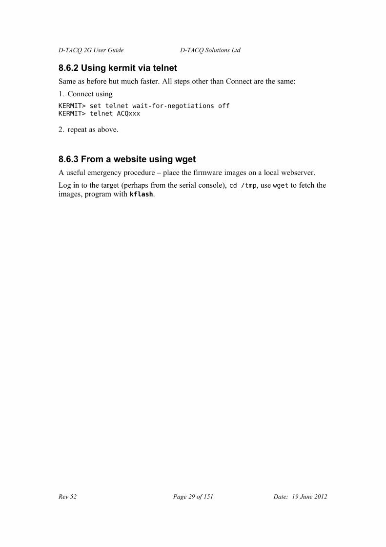
9.2.7 Calibration Table Example:
<?xml version="1.0" standalone="no" ?><ACQ> <!-- m2-hiZ.xml $Revision: 1.1 $ special M2 with HiZ has smaller ranges on lower settings --> <!-- calibration data --> <AcqCalibration> <Info> <CalDate>20070331:12:15</CalDate> <Version>$RCSfile: calibrate.cpp,v $ $Revision: 1.26 $ B1038</Version> <Model>ACQ216-M2</Model> <Serialnum>d41023</Serialnum> </Info> <Data AICHAN="16" polarity="REVERSED" code_min="-32768" code_max="32764" <Range name="1.6" sw="0,0"> <Nominal min="-1.6" max="1.6" /> <Calibrated ch="2" min="-1.594217" max="1.598378" /> <Calibrated ch="3" min="-1.580590" max="1.536258" /> ... <Calibrated ch="16" min="-1.643807" max="1.625098" /> </Range> <Range name="2.5" sw="1,0"> <Nominal min="-2.5" max="2.5" /> <Calibrated ch="2" min="-2.561408" max="2.565410" /> <Calibrated ch="3" min="-2.524193" max="2.479898" /> ... <Calibrated ch="16" min="-2.633520" max="2.614286" /> </Range> <Range name="6" sw="0,1"> <Nominal min="-6" max="6" /> <Calibrated ch="2" min="-6.373147" max="6.423854" /> <Calibrated ch="3" min="-6.293885" max="6.168747" /> ... <Calibrated ch="16" min="-10.553202" max="10.469114" /> </Range> </Data> </AcqCalibration> <ModelSpec> <ChannelBlockMask> <BlockWidth>4</BlockWidth> <BlockSet>"1111","1110","1100","1 </ChannelBlockMask> <MaxAggregateRate>400 MB/sec</MaxAggregateRate> <MaxDeviceRate>50 MS/sec</MaxDeviceRate> <MinDeviceRate>1 MS/sec</MinDeviceRate> <CalClock>10000000</CalClock> <CalMeanN>1024000</CalMeanN> </ModelSpec> </ACQ>
Rev 52 Page 35 of 151 Date: 19 June 2012

D-TACQ 2G User Guide D-TACQ Solutions Ltd
10 Command Reference.For a complete comparison of acqcmd, acqcmd -b, acqcmd -s, acq2sh and just shell, please see #19.3
10.1 Operating Modes
The card will capture data in one of a number of modes.
• SOFT_TRANSIENT - a simple one shot capture
• SOFT_CONTINUOUS - continuous capture
• GATED_TRANSIENT - a one shot with a start trigger
• TRIGGEREDCONTINUOUS - "Pre/Post" capture, where the card captures data continuously to a circular buffer, until an external Event is received, when the card switches to a linear buffer, continues to capture data for a specified length and then stops.
There is complete flexibility over setting a start TRIGGER to enable any of the above captures, and the EVENT that controls transition from Pre- to Post- in TRIGGEREDCONTINUOUS mode is also use-specified.
A single command "set.pre_post_mode" is recommended to simplify client setup.
10.1.1 Linear Timebase
The default operating mode is to capture data continuously with a fixed clock. So the timebase of the data maps exactly to the sample clock times. Usually the clock is continuous and fixed, so this is referred to as a Linear timebase.
10.1.2 Regions of Interest - PRE Programmed triggers.
The normal pre/post mode of operation is to capture data continuously to a cyclic buffer until an external Event is received. In this case, usually all historical data is discarded, unless it is streamed off-board, usually at a sub-rate. However, under some circumstances, it is desirable to declare "Regions of Interest" at known times. On ACQxxx, this is the Preprogrammed Trigger (PREP) mechanism, and any number of PREP's can be defined. For detail see 14
10.1.3 Discontiguous Timebase: Repeating Gate Mode
Continuous timebase is effective on ACQxxx cards because of the large on-board memory, and the capability to stream data continuously. However, certain applications (laser strobing, radar/sonar pulses, probe plunging), the data of interest is bounded by a gate, and in this case makes no sense to capture data while the GATE (and therefore the signal) is OFF. Repeating Gate Mode [10.4.4] allows the user to specify that capture to be controlled by the Gate pulse. This allows for easy synchronization to the GATE pulse, and, importantly has potential for massive data reduction. Data is store to memory as a series of bursts. The data in memory no longer maps to linear time; however the card provides a timestamp with each burst to enable a linear timebase to be reconstructed for the data.
Rev 52 Page 36 of 151 Date: 19 June 2012

D-TACQ 2G User Guide D-TACQ Solutions Ltd
10.1.4 Random Multiple Events: MULTIVENT
ACQ132CPCI can be configured to accept random multiple events. Capture proceeds continuously. User specifies a region of interest with PRE, POST samples, and, on each event the surrounding raw data is reserved, and post processed. The data is made available in channelized format in a unique, network accessible directory. After consuming the data, a remote application can delete the directory, recycling the data. In this way, MULTIVENT can run indefinately, provided the average event rate does not cause the local DRAM to overflow.
MULTIVENT is described in detail in a separate document.
Rev 52 Page 37 of 151 Date: 19 June 2012

D-TACQ 2G User Guide D-TACQ Solutions Ltd
10.2 acqcmd Interface: (see ICD)
In addition, the basic Operating Modes are enhanced, by provision of
• User specified Trigger -
A Trigger is a digital input transition that starts a capture. In contrast to 1G where the trigger was a implied by the various modes, and the LINE and EDGE was fixed, in 2G the user can specify both LINE and EDGE. In order to user a trigger, it MUST be explicitly specified, and more generally, if a trigger is specified, it will apply regardless of Mode.
i.e.: if a trigger is specified, it will start capture, otherwise the capture is soft triggered.
• User specified Event -
Event is a digital input causing a transition from one Phase to another, at the moment only two Phases are defined (pre-, post-), and this in the SOFT_CONTINUOUS, TRIGGEREDCONTINUOUS modes.
In the same way as with the Trigger, LINE and EDGE is user definable.
Example Use:
• Traditional one shot capture:
Set Trigger, set Mode GATED_TRANSIENT (SOFT_TRANSIENT is equivalent if a Trigger is defined).
• Traditional pre-, post capture.
Set Event, setModeTriggeredContinuous, it is assumed that the pre- buffer is filled before event.
• Synchronized Streaming:
On multiple boards, set Trigger to be the same, mode SOFT_CONTINUOUS, all boards start on Trigger.
Please note, that, at this time, the “Enhanced Software Operation” modes (GPEM) are not available on 2G. However, it's also clear that, with user choice of Trigger and Event (s), equivalent functionality is to a large extent available.
10.3 dt100 remote interface
(see ICD, superceded by Section 20.1.
10.4 Shell command interface
Preferred way to add new functionality is via the shell command interface.
When operating as a two tier system using the dt100d server, shell commands are accessed via a connection configured using dt100 open shell from the dt100 remote interface. (See #20.1).
Rev 52 Page 38 of 151 Date: 19 June 2012

D-TACQ 2G User Guide D-TACQ Solutions Ltd
When operating via the PCI or dt100-hub interfaces, shell commands are accessed via the rsh pseudo-device
eg
acqcmd -f /dev/acq200/acq200.5.rsh hostname
acqcmd supports a short cut notation -s
acqcmd -s 5 hostname
A number of rsh scripts are implemented:
10.4.1 High level command Clock Role setting
ACQ1xx includes a flexible clock and trigger system. This allows lots of options that may be set individually. However, at least to start, D-TACQ recommends using the following role-base commands to set the clock scenario.
set.acq196.role ROLE [CLKKHZ]
set.acq132.role ROLE [CLKKHZ]
set.acq164.role ROLE [CLKKHZ]
• set.acq196.role ROLE [CLKKHZ]
• set.acq132.role ROLE [CLKKHZ]
• set.acq132.role ROLE [CLKKHZ]
Where role is one of SOLO|MASTER|SLAVE and CLKKHZ is a valid output clock rate for the device.
On ACQ164, this command takes care of the additional SYNC signal routing, and selects the best ADC MODE based on sample rate.On ACQ132, an additonal oversampling command 23.2.1may be needed to set exact oversampling condition.
10.4.2 Signals
Signals is the generic terms for
• Clocks - determine the instant of sampling
• Triggers - cause the start of a shot
• Event - places a marker in the data stream. Typically an Event will cause transition from pre- phase to post- phase.
Rev 52 Page 39 of 151 Date: 19 June 2012

D-TACQ 2G User Guide D-TACQ Solutions Ltd
10.4.2.1 Clock and trigger Routing
ACQ196CPCI, ACQ216CPCI, WAV232CPCI all feature clock and trigger routing capability on 6 dedicated DIO lines. This arrangement differs from previous generation ACQ32CPCI in terms of technology – instead of solid state switches, a line driver is used for higher performance at higher clock speeds.
These commands supercede “acqcmd setSyncRoute” found on ACQ32CPCI.
• DI[0-2] – recommended for Clocks – DO NOT SUPPORT “Wire OR”
• DI[3-5] – recommended for Trigger – open collector drivers, support Wire OR for “any board can declare a trigger applications”.
LINE Default functionDI0 External ClockDI1DI2DI3 External TriggerDI4DI5
Source Description NotesMezz Front panel input LEMO DI0 : CLK
DI3 : TRG
others: not connectedFpga Local DIO output Useful for driving other
cardsRio Local Rear IO inputs Depends on RTMPxi Backplane PXI signaling
One source can be routed to multiple destinations:
Destination. Description NotesFpga Local DIO input Always needed to respond to
incoming signalsRio Local Rear IO outputs Depends on RTMPxi Backplane PXI signaling Slave from other cards
Diagnostic and control available at http:/cgi-bin/dio.cgi
Scripted control via set.route:
Rev 52 Page 40 of 151 Date: 19 June 2012

D-TACQ 2G User Guide D-TACQ Solutions Ltd
set.route dX in {input} out {outputs}
Examples:
• Single card slaved from front panel.
# take trg in lemo, use locally only:set.route D3 in mezz out fpga
• Master card distributes front panel LEMO signal to self and rack
# source trigger from mezza out fpga INPUT, pxi:set.route D3 in mezz out fpga pxi
• Slave card from pxi
# source trigger from pxi to fpga INPUTset.route D3 in pxi out fpga
• Master card in rack, self clocking
# source trigger from fpga OUTPUT, drive pxi:set.route D3 in fpga out pxi
• Internal Clock on Master card can clock other cards:
# source clock on masterset.route D0 in fpga out pxi# enable clk mastering
set.InternalClock NNN DO0
# ensure D0 is an output.
setDIO 0-----
Rev 52 Page 41 of 151 Date: 19 June 2012

D-TACQ 2G User Guide D-TACQ Solutions Ltd
10.4.2.2 Clock Selection
Individual Clocks can be defined as follows:
# Command Function
1 set.ext_clk DIx edge Define external (AI) clock
2 set.int_clk_src DIx edge Define internal clock source
(in clock divider mode)
3 mas_clk DOx| Output for InternalClock
4 counter_src DIx edge Source for counter unit
5* set.ao_clk DI[012] Define AO clock
6 sync_trig_src DIx edge|| Source for sync trig
7 sync_trig_mas DOx Output for sync trig
* ACQ196 ONLY
DIx : DI[012345]
DOx : DO[012345]
edge : falling|rising
10.4.2.3 Trigger Selection
A trigger is a one shot edge used to start a one shot capture eg GATED_TRANSIENT
Software is able to select one of DI3, DI4, DI5 and rising | falling edge.
set.trig DIx sense
DIx {DI3, DI4, DI5 }sense {falling, rising}
eg:set.trig DI3 falling;# emulate GATED_TRANSIENT behaviour.
set.trig none # cancel the trigger selection
Be sure to use set.trig none for a subsequent capture when no trigger is required.
The AO function has its own trigger:
set.ao_trig DIx edge| Define AO trigger
Rev 52 Page 42 of 151 Date: 19 June 2012

D-TACQ 2G User Guide D-TACQ Solutions Ltd
10.4.2.4 Event selection
An event is a digital edge detected after capture starts. Typically this causes a phase transition (eg pre to post).
ACQ[12]xx features detection of two separately defined events.
Set.event allows local specification of event to be used:
set.event eventE DIx sense
eventE {event0 | event1}DIx {DI3, DI4, DI5 }sense {falling, rising}
eg:set.event event0 DI3 falling ;# emulate TriggeredContinuous behaviour
Report existing setting with:
get.event eventE {event0 | event1}
# Alternate notation
set.event0 Dix sense
# Cancellation
set.event0 noneset.event event0 none
It is recommended that the event definition be re-asserted before each capture.
Rev 52 Page 43 of 151 Date: 19 June 2012

D-TACQ 2G User Guide D-TACQ Solutions Ltd
10.4.3 Generic Pre/Post Modeset.pre_post_mode pre post [dix [sense] ]
get.pre_post_mode
These are high level commands to simplify mode selection and to replace both:
set.event0 dix senseacqcmd setModeTriggeredContinuous pre post
andset.trig dix senseacqcmd setMode GATED_TRANSIENT post
set·pre_post_mode makes the decision on which technique to use based on the values of pre, post; this relieves application code of this complexity and is STRONGLY RECOMMENDED for new interface designs.
Example:set.pre_post_mode 10240 4000000 DI3 falling
# continuous capture to pre-buffer, change phase to post-buffer on DI3 falling, finish up with 10240 samples pre and 4000000 samples post.
Rev 52 Page 44 of 151 Date: 19 June 2012

D-TACQ 2G User Guide D-TACQ Solutions Ltd
10.4.4 Repeating Gate Mode
Allows operation with discontiguous timebase. The card is first configured with one of the major modes (typically SOFT_TRANSIENT). The command to enable Repeating Gate Mode is:
set.dtacq RepeatingGateMode MODE TLEN
The Gate signal is Event0, and any of lines d3,d4,d5,[d0,d1,d2] may be selected together with programmable sense. On ACQ132CPCI ONLY, a separate gate source control is provided:
set.gate_src DIx {high|low}
Three separate Modes are implemented:
Value MODE TLEN Description
0 OFF X Disable (Contiguous Timebase)
1 TRAN 1..65535 Start on Event0 Active Edge
End after TLEN samples.
2 GATE X Start on Event0 Active Edge,
End on Event0 Inactive Edge.
3 TRAN+GATE
1..65535 Start on Event0 Active Edge
End on first of TLEN samples or Event0 Inactive Edge.
Each block of data in memory is preceded by an Event Signature ES and a 32-bit timestamp. The timestamp is driven from the internal time counter, which is set up in the normal way.
There are two ways to view the data:
1. Upload Raw Data and postprocess on a Host Computer - D-TACQ supplies the rgm shared library and rgm_dump utility to do this.
2. Onboard post-processing. Each channel is presented as a linear data set, together with an additional timebase vector on a dummy "channel". Client software (such as MDSplus) can plot channel vs linear time by plotting the channel data vs timebase.
10.4.4.1 Clock Options
The sample clock can be a "InternalClockMaster" where one designated card drives a 500kHz clock on the PXI backplane so that all cards clock simultaneously.
Alternatively, and external 500kHz clock can feed in the front panel of one card "LemoClockMaster", and this card again will feed the clock to all slaves.
By default, the Timestamp is driven from the sample clock. However, in a third possibility "Sysclock", a 1MHz SYSCLK is feeds the front panel LEMO of the
Rev 52 Page 45 of 151 Date: 19 June 2012

D-TACQ 2G User Guide D-TACQ Solutions Ltd
"SysclkMaster" card. The 1MHz clock is distributed on PXI and drives all the timestamp counter. Separately, the Master card divides SYSCLK by two to generate the Sample clock, and this is distributed to all cards on a separate PXI line.
10.4.5 Input Voltage Range
Certain models have input voltage selection (most ACQ216CPCI mezzanines).
To set all the channels to the same range:
set.vin range-key
egset.vin 3-3.0000,3.0000
To set a selection of channels to a voltage range:
set.vin selection range-key
selection: channel channel1[,channel2]channel1-channel2
To find out the valid set of range-key values :
get.vin range-keys
get.vin range-keys"30","50","625","1","1.9","3"
Example:
• Set all channels to Range 3 (V)
set.vin 1-16 3-3.0000,3.0000-3.0000,3.0000-3.0000,3.0000-3.0000,3.0000-3.0000,3.0000-3.0000,3.0000-3.0000,3.0000-3.0000,3.0000-3.0000,3.0000-3.0000,3.0000-3.0000,3.0000-3.0000,3.0000-3.0000,3.0000-3.0000,3.0000-3.0000,3.0000-3.0000,3.0000
• Set channel 3 to Range 625 (mV)
#set.vin 3 625-3.0000,3.0000-3.0000,3.0000-0.6250,0.6250-3.0000,3.0000-3.0000,3.0000-3.0000,3.0000-3.0000,3.0000-3.0000,3.0000-3.0000,3.0000-3.0000,3.0000-3.0000,3.0000-3.0000,3.0000-3.0000,3.0000-3.0000,3.0000-3.0000,3.0000-3.0000,3.0000
• Set channels 10-16 to Range 1 (V)
set.vin 10-16 1
Rev 52 Page 46 of 151 Date: 19 June 2012

D-TACQ 2G User Guide D-TACQ Solutions Ltd
-3.0000,3.0000-3.0000,3.0000-0.6250,0.6250-3.0000,3.0000-3.0000,3.0000-3.0000,3.0000-3.0000,3.0000-3.0000,3.0000-3.0000,3.0000-1.0000,1.0000-1.0000,1.0000-1.0000,1.0000-1.0000,1.0000-1.0000,1.0000-1.0000,1.0000-1.0000,1.0000
To Read the voltage range, acqcmd getVoltsRange is provided for back compatibility, it will return the values of the largest selected range:
eg
acqcmd getVoltsRangeACQ32:getVoltsRange AI=-3.0V,3.0V AO=-10.0V,10.0V
To recover the actual range that each channel is set to, including any calibration:
get.vin-3.0000,3.0000,-3.0000,3.0000,-0.6250,0.6250,-3.0000,3.0000,-3.0000,3.0000,-3.0000,3.0000,-3.0000,3.0000,-3.0000,3.0000,-3.0000,3.0000,-1.0000,1.0000,-1.0000,1.0000,-1.0000,1.0000,-1.0000,1.0000,-1.0000,1.0000,-1.0000,1.0000,-1.0000,1.0000
(if a calibrated range is not available, this command returns the default:)
(see http:/cgi-bin/vin.cgi for diagnostic).
It is of course also possible for any remote client to pick up the underlying XML calibration file (/etc/cal/caldef.xml) and to use this directly.
10.4.6 Channel Mask and Channel Count
This replaces acqcmd setChannelMask, acqcmd getChannelMask with an implementation that works better for 96 channels on ACQ196:
acq2sh set.channelMask {1,3,7}{2,4,5,6 also valid but less likely} acq2sh get.channelMask reports setting (in hex). acq2sh get.numChannels reports number of channels enabled by the mask
10.4.7 Block Technique for Setting Channel Mask
Not all possible combinations of channel mask are supported by hardware.For example, on ACQ196, channels are enabled in blocks of 32 channels.Using the original command setChannelMask, the only way to deduce this is to set a channel mask and then to see what you got:
ACQ196 Example:
Rev 52 Page 47 of 151 Date: 19 June 2012

D-TACQ 2G User Guide D-TACQ Solutions Ltd
acqcmd setChannelMask 1ACQ32:acqcmd getChannelMaskACQ32:getChannelMask=111111111111111111111111111111110000000000000000000000000000000000000000000000000000000000000000
A more deterministic way to do this is by use of Channel Block commands.
• get.modelspec ChannelBlockMask.BlockWidth :returns width of each maskable channel block in channels
• get.modelspec ChannelBlockMask.BlockSet:returns the selection of channel block masks that have meaning on this platform.
ACQ196 Example - blocks of 32 channels
get.modelspec ChannelBlockMask.BlockWidth32get.modelspec ChannelBlockMask.BlockSet"111","110","101","011","100","010","001"
ACQ216 Example - blocks of 4 channels, grouped from lowest logical channel
get.modelspec ChannelBlockMask.BlockWidth4get.modelspec ChannelBlockMask.BlockSet"1111","1110","1100","1000"
Use this information as follows:• set.channelBlockMask <mask>• get.channelBlockMask
ACQ216 Example - setting a channel mask using block commands
#set.channelBlockMask 1100acqcmd -- setChannelMask 1111111100000000
ACQ32:
acqcmd getChannelMaskACQ32:getChannelMask=1111111100000000
10.4.8 Access fields in calibration file.
Default calibration file /etc/cal/caldef.xml contains all calibration and other useful parameters for the card. Applications may load and parse this file directly
Rev 52 Page 48 of 151 Date: 19 June 2012

D-TACQ 2G User Guide D-TACQ Solutions Ltd
eg
• acq2sh cat /etc/cal/caldef.xml• wget http:/hostname/etc/cal/caldef.xml
Or it is possible to extract selected fields using
• get.caldef <field>• get.modelspec <field>
get.caldef Info.CalDate20041225get.caldef Info.VersionB1007get.caldef Info.ModelACQ196get.caldef Info.Serialnumd30000get.modelspec ChannelBlockMask.BlockWidth32get.modelspec ChannelBlockMask.BlockSet"111","110","101","011","100","010","001"get.modelspec MaxAggregateRate80 MB/secget.modelspec MaxDeviceRate500 kS/sec
10.4.9 set.autozero : start an autozero process (Acq196 only)
Assumes all inputs are open circuit.
Ramps input offset adjustment until all channels are zero calibrated, storing values for use next boot.
Rev 52 Page 49 of 151 Date: 19 June 2012

D-TACQ 2G User Guide D-TACQ Solutions Ltd
10.4.10 Analog Output Control
ACQ196CPCI- RTM-AO16 only
16 analog outputs with software control of DC values and Arbitrary Waveform Generation (AWG) capability. Two types of arbitrary waveform are supported:
• Hardware Arbitrary Waveform (HAWG)
• Software (FIFO) Arbitrary Waveform (FAWG).
At this time the HAWG is restricted to channels 01, 02, and 512 points maximum, but will run under hardware control at full speed (1000kHz), while the FAWG allows 16384 points maximum on all 16 channels, but with update rate controlled by an auxilliary timer interrupt., with a maximum practical update rate of 500kHz.
In general, use FAWG unless very high update rates are required.
The HAWG is designed for exact sample by sample matching with custom FPGA DSP firmware.
In either case, the firmware interface is virtually the same.
It should also be noted that the AWG is competing for local bus bandwidth with the acquisition process, as well as any Ethernet traffic, and full speed operation on all functions may not be possible. This trade off is roughly:
• AI > 100KSPS, AO < 25kSPS.
Please contact D-TACQ for evaluation of specific requirements.
10.4.10.1 Clock and Trigger
The AO function may use internal or external clock.
The AO function may use external trigger or soft trigger.
AO clock and trigger function is selected independently to the AI functions.
ie: AO clock/trigger can be the same, or it can be different to AI.
The default and most common setting for the AO clock is to simply slave off the internal clock.
NB: if no external trigger is used, a soft trigger MUST be explicitly asserted in order to change AO waveforms. DC values are not affected by trigger.
set.ao_clk DIx senseset.ao_trig DIx sense
DIx {DI3, DI4, DI5 }sense {falling, rising}
eg:set.ao_trig DI3 falling;# emulate GATED_TRANSIENT behaviour.set.ao_trig none # cancel the trigger selection
Rev 52 Page 50 of 151 Date: 19 June 2012

D-TACQ 2G User Guide D-TACQ Solutions Ltd
10.4.10.2 Logical Device Nodes:
Driver provides the following device nodes. Access through set.AO is preferred, although for speed a client application may use direct access.
root@acq196_001 ~ #ls -1 /dev/acq196/AO01 ;# load ascii hex voltage def here0203...1516XX ;# load value to all channelscommit ;# 1=> commit DC, 2 => commit AWGf.01 ;# load binary waveform heref.02f.03 ;# FAWG only from here...f.16coding ;# signed | unsigned
10.4.10.3 DC Control
Write a numeric representation of the raw output value to any/all of /dev/acq196/AO/cc
Examples:
echo 32767 > /dev/acq196/AO/01echo -32768 > /dev/acq196/AO/01
# change by delta:echo p10 >/dev/acq196/AO/01 # increment 10 stepsecho m10 >/dev/acq196/AO/01 # decrement 10 steps
For prototype and test purposes, please refer to cgi-bin/AO.cgi –
this provides a simple control panel to exercise the AO channels.
Each AO channel is represented by a logical device node and a script
/usr/local/bin/set.AO
is provided to give access to the AO channels. The script allows simple access from remote clients and cgi-scripts.
More formally, first, set the values in buffer memory:
Rev 52 Page 51 of 151 Date: 19 June 2012

D-TACQ 2G User Guide D-TACQ Solutions Ltd
set.AO <channel> <value> : <channel: 01..16, XX (all channels)>,<value: decimal-value> :
decimal-value: -32768 .. 32767
The voltage coding is as specified in /dev/acq196/AO/coding, and it is anticipated that a default value will be set at boot time (eg by /ffs/rc.local boot script).
Then commit the values to hardware as follows:set.AO commit 1
10.4.10.4 Hardware AWG "HAWG"
A hardware AWG function is available for channels 1 and 2. The HAWG has a maximum length of 512 samples.
To configure HAWG:
1. Copy the data to the appropriate device node:
cat my-binary-data >/dev/acq196/AO/f.01
NB: this data is raw binary (not ascii as per the DC nodes), and the voltage coding should match the selection in /dev/acq196/AO/coding.
2. Start the waveform with a commit 2:
set.AO commit 2 # hardware triggerset.AO commit 18 # soft trigger
Two canned waveforms are provided:
set.AO <channel> sinset.AO <channel> saw
set.AO has provision for two User Waveforms, to be stored on the FFS partition:
set.AO <channel> arb
Two make this work, store user binary waveforms in
/ffs/AO.awg.01/ffs/AO.awg.02
The files should contain binary data, max length 256 samples.
If one data set is longer than the other, the channel with the shorter data set will have the last value repeated up to the end of the longer data set.
Rev 52 Page 52 of 151 Date: 19 June 2012

D-TACQ 2G User Guide D-TACQ Solutions Ltd
Please note that the HAWG function is repeated until stopped (HOW?), and may either be software triggered or triggered by external hardware event, in the same way as the AI capture. The AO trigger is independent of the AI trigger, but may be set to the same value as required.
10.4.10.5 Fifo AWG "FAWG"
As before, write binary waveforms to each required channel /dev/acq196/AO/f.XX
• max points 16384 - 8s @ 2KHz:
cat /sys/module/acq196/parameters/fawg_max_samples
• Start: set.arm.AO.FAWG [opts]
• Stop: set.AO commit 0
The FAWG will replay all channels, up to the length of the longest channel definition.
If a channel definition is shorter than the longest, the last value in the definition is repeated until end of buffer. If the channel definition has zero length, the DC value is used.
A sample FAWG test routine is supplied in /usr/local/CARE/acq196.FAWG.test
FAWG update rate - reading data out of the FIFO is the AI sample clock divided by FAWG_DIV {1..255}
/dev/dtacq/FAWG_DIV : controls the output data rate as a fraction of AI sample rate.
10.4.10.6 FAWG Options
FAWG operation is controlled by set.arm.AO.FAWG.
This arranges for the underlying commit value to be set at the appropriate time.
set.arm.AO.FAWG [opts] :ONCE | CYCLIC [default] : repetition modeSOFT_TRIG | HARD_TRIG [default] : triggerIMMEDIATE | [default: write on setArm] : when to commit the value
The default option [no args] is to schedule a hard triggered cyclic waveform to be armed at setArm. IMMEDIATE means arm immediately, NB: this will not work for the case of a ONCE one shot operation.
• Range of values for set.AO commit
commit is set as a combination of binary bit flags.
#define COMMIT_DC 0x01 /** set DC output */
Rev 52 Page 53 of 151 Date: 19 June 2012

D-TACQ 2G User Guide D-TACQ Solutions Ltd
#define COMMIT_HAWG 0x02 /** initiate HAWG output on trigger */#define COMMIT_FAWG 0x04 /** initiate FAWG output on trigger */#define COMMIT_REF 0x08 /** enables REF output (MAC fw only) */#define COMMIT_TRIG 0x10 /** software trigger on commit */#define COMMIT_ONESHOT 0x20 /** oneshot FAWG action when enabled */#define COMMIT_CONTINUOUS 0x40 /** continuous data feed */
/** default is cyclic repeat */
Rev 52 Page 54 of 151 Date: 19 June 2012

D-TACQ 2G User Guide D-TACQ Solutions Ltd
10.4.10.7 FAWG Example:
# assume clock routing has already been made
set.ao_clk DI0 falling set.ao_trig DI3 falling set.dtacq FAWG_div 20 # output DI0 / 20
# for AI clock < 100kHz, can use FAWG_div==1
# now generate some datafungen --cycle 1 4 0 2.5 fungen --cycle 2 5 0 2 fungen --cycle 3 6 0 1.5
# or fetch it with curl:curl -s -o /dev/acq196/AO/f.#1 ftp://anonymous@host/pub/f.[01-16]
# or push it with curl (assumes embedded ftp server running)
cat mydata | curl -T - -u ao: ftp://target/AO/f.01
# or simply transfer by hand with good old ftp
# configure hooks to start process with main AI capture:
set.arm.AO.FAWG CYCLIC HARD_TRIG
# sometime later - configure AI and setArm
Rev 52 Page 55 of 151 Date: 19 June 2012

D-TACQ 2G User Guide D-TACQ Solutions Ltd
10.4.10.8 Function Generator
A simple function generator program for use with the FAWG is supplied:
fungen channel [K] [A] [nsam]
function is channel = K + A sin (wt) (nsam samples). K, A are floating point volts. Takes about 30msec to generate 64 points. 64 points should be more than enough for a typical coil drive.Phase Control:
usage: fungen --sin -- ch K A [N] [P]usage: fungen --cos -- ch K A [N] [P]
ch: channel 1..16K,A : offset, amplitude in volts (floating point)N : number of samples per cycle (integer)P : phase adjust (samples).
Example Script:
root@acq196_001 #for ch in 1 2 3 4 5 6 7 8 9 10 11 12 13 14 15 16do
let v="$ch-10"fungen $ch $v
done
ch:01 -9.00 + 1.00 * sin(wt) [64]ch:02 -8.00 + 1.00 * sin(wt) [64]ch:03 -7.00 + 1.00 * sin(wt) [64]ch:04 -6.00 + 1.00 * sin(wt) [64]ch:05 -5.00 + 1.00 * sin(wt) [64]ch:06 -4.00 + 1.00 * sin(wt) [64]ch:07 -3.00 + 1.00 * sin(wt) [64]ch:08 -2.00 + 1.00 * sin(wt) [64]ch:09 -1.00 + 1.00 * sin(wt) [64]ch:10 0.00 + 1.00 * sin(wt) [64]ch:11 1.00 + 1.00 * sin(wt) [64]ch:12 2.00 + 1.00 * sin(wt) [64]ch:13 3.00 + 1.00 * sin(wt) [64]ch:14 4.00 + 1.00 * sin(wt) [64]ch:15 5.00 + 1.00 * sin(wt) [64]ch:16 6.00 + 1.00 * sin(wt) [64]
Rev 52 Page 56 of 151 Date: 19 June 2012

D-TACQ 2G User Guide D-TACQ Solutions Ltd
10.4.10.9 Function Generator Service
While fungen may be operated in batch mode from the command line (or using acq2sh commands), for interactive use this is a little sluggish, and so there is a high performance interactive mode, this runs as service on port 53506 under inetd. The service may be accessed via telnet, or more typically via a remote program; for example dt100rc.
Example:
Start the service on the target ( this command may be placed in /ffs/rc.local )
start.fungen.service
From a remote machine:
[pgm@islay ~]$ telnet acq196_001 53505Trying 192.168.0.156...Connected to acq196_001.localnet (192.168.0.156).Escape character is '^]'.fungen>--autocommit 20 --sin 3 1 0.5 641 OKfungen>--autocommit 20 --sin 3 1 2 642 OKfungen>commit 203 OKfungen>--sin -- 1 1 1 644 OKfungen>--cos -- 2 2 2 645 OKfungen>--sin -- 3 -1 2 646 OKfungen>commit 207 OKfungen>--autocommit 20 --sin -- 3 1 0.5 648 OK
Rev 52 Page 57 of 151 Date: 19 June 2012

D-TACQ 2G User Guide D-TACQ Solutions Ltd
fungen>--autocommit 20 --sin -- 3 1 1 64 109 OK
fungen caches the sine wave as a lookup table, assuming best performance when all the waveform have same number of samples (amplitude, offset and phase are all derived from the LUT data).
Waveforms are not written to the hardware until the commit action.
For the case of updating multiple channels it is best to commit at the end.
For the case of interactively updating a single channel, the --autocommit option will commit the channel data without the need for a separate command.
Rev 52 Page 58 of 151 Date: 19 June 2012

D-TACQ 2G User Guide D-TACQ Solutions Ltd
10.4.10.10 Test Sequence
The RTM-AO16 makes for an easy loopback test as follows:
• connect a S68 cable from AO connector to AI to run a loopback test.
• use Mozilla to connect to <target-ip>/cgi-bin/AO.cgi
• push "Ident" followed by "commit DC" to set up an identity set.
• capture some data and you should see the pretty ident picture.
• push "sin 1", "saw 2", commit DC+AWG, capture again to get second picture with waveforms.
Rev 52 Page 59 of 151 Date: 19 June 2012

D-TACQ 2G User Guide D-TACQ Solutions Ltd
10.4.11 RTM DIO32 Control
RTM features 32 bits programmable dio.
The RTM device driver is not loaded by default.
load.rtm ;# should be loaded at boot time eg via /ffs/rc.local
set.DIO32 <diopattern>get.DIO32 outputs: dioreadbackpattern
<diopattern> : [pat0[pat1[pat2 ... [pat32]]]
patX : X denotes bit number, values of X :'-' : input, '1' : output 1, '0': output 0,'x' : ignore
dioreadbackpattern : r0r1r2r3....r32
rX : 'L' : input LO, 'H': input HI, '1':output 1, '0': output 0.
eg:
set.DIO32 11110000----------------- # 4 HI, 4 LO, rest inputget.DIO32 11110000HHHHHHHHHHHHHHHHHHHH
set.DIO32 xxxx1xxxxx # set bit 4 onlyset.DIO32 xxxx0xxxxx # clear bit 4 onlyset.DIO32 xxxxP # Positive pulse, bit 4set.DIO32 xxxxN # Negative pulse, bit 4
It is also possible to access this control directly through the following device node:
/dev/dio32
10.4.12 Timer Counter
2G cards are equipped with a 32 bit clock counter module. The counter source may be selected from any one of DI0-5 or Internal clock. The counter starts counting when acquisition is triggered. An Immediate Count value may be queried at any time. A second value, Latched Count, may be configured to latch on the first occurrence of a selectable event – this can be Sample, Event0 or Event1.
A typical use for the Counter is to count an extenal fixed clock (1Mhz, say), with the latch source set to Event0, providing a fixed measure of the time to the first event. This is then a direct and independent measure, that can either be used to verify the time of the event as measured by sample number, or, if the counter source clock is faster than the sample clock, to give a more precise measurement of the time
Rev 52 Page 60 of 151 Date: 19 June 2012

D-TACQ 2G User Guide D-TACQ Solutions Ltd
of the event.
The function is controlled and monitored via the following shell commands:
• set.counter_src DIx
• get.counter_src
• set.counter_update [0,1,2] [sample, event0, event1]
• get.counter_update
• get.dtacq clock_count_immediate
• get.dtacq clock_count_latched
Rev 52 Page 61 of 151 Date: 19 June 2012

D-TACQ 2G User Guide D-TACQ Solutions Ltd
10.4.13 Monitor state with acqstate / statemon.
It is possible to block on state changes by reading the node /dev/tblocks/acqstate.
This can be used as the basis for efficient event driven test sequences.
State change information is also available as an internet service:
To start the service, un-comment the “STATED” option in /ffs/rc.local.options
The state server may also be combined with a “remote client in the loop” hardware watchdog, to make use of this facility:
To allow use of the watchdog, un-comment the "WDT" option in /ffs/rc.local.options
The service is available from other networked computers on port 53535, for example:
[pgm@islay CARE]$ telnet acq196_010 53535Trying 192.168.0.154...Connected to acq196_010.localnet (192.168.0.154).Escape character is '^]'.78106.75 0 ST_STOP78106.81 1 ST_ARM78106.82 2 ST_RUN78106.88 5 ST_CAPDONE78106.94 4 ST_POSTPROCESS78107.75 0 ST_STOP
The timestamp is in seconds from midnight.
This remote service may be easily incorporated into remote controller scripts eg using expect(1). This is superior to polling for state changes eg using acqcmd --until, since no event transitions are missed, while at the same time it has negligible loading on the embedded computer.
The acqstate service is actually implemented using the statemon program, and this has some additional options, commands available on the input:
● Set a heartbeat in seconds:
heartbeat=N
● Remote watchdog:
watchdog
The heartbeat prints a time-stamped report event N seconds.
The watchdog command enables the hardware watchdog, and, once enabled, the remote client must issue repeat "watchdog" commands with a maximum 12 s interval, or the hardware watchdog time will fire, rebooting the card. Once enabled, the hardware watchdog cannot be disabled.
It is anticipated that these commands will be used in electrically harsh environments, where electrical noise could be interfering with either the Ethernet or correct
Rev 52 Page 62 of 151 Date: 19 June 2012

D-TACQ 2G User Guide D-TACQ Solutions Ltd
operation of the card itself.
The networked watchdog enables "host-in-the-loop" watchdog control - the client application could implement as test-oriented policy, such as only refreshing the watchdog when data is received.
A verbose version of the same service is supported at port 53536:
This offers a sign on message containing the current state, and prints number of samples and state on every transition to stop. A remote status monitor program could connect to this service and show system status with no polling at all.
nc 192.168.1.237 53536D-TACQ statemon:$Revision: 1.18 $ B1008 50542.34 0 ST_STOP SHOT=20 ACQ32:getNumSamples=40003584 pre=0 post=40003584 elapsed=40003584
OK 50546.29 1 ST_ARM 50546.41 2 ST_RUN 50547.21 5 ST_CAPDONE 50547.63 4 ST_POSTPROCESS 50570.25 0 ST_STOP SHOT=21 ACQ32:getNumSamples=40003584 pre=0 post=40003584 elapsed=40003584
An example remote client is FUNCTIONAL_TESTS/time-states.py
This progam lists the time spend in each state.
[pgm@hoy2 FUNCTIONAL_TESTS]$ ./time-states.py 192.168.1.237:10015 ST_ARM : 0.09 ST_RUN : 4.00 ST_CAPDONE : 0.41 ST_POSTPROCESS :22.74 ST_ARM : 0.06 ST_RUN : 0.80 ST_CAPDONE : 0.41 ST_POSTPROCESS :23.22
Rev 52 Page 63 of 151 Date: 19 June 2012

D-TACQ 2G User Guide D-TACQ Solutions Ltd
Sample Dialog:
D_TACQ statemon:$Revision:1$ heartbeat=1 heartbeat ENABLED OK 33531.93 timestamp 33532.93 timestamp 33533.37 0 ST_STOP 33533.93 1 ST_ARM 33533.93 2 ST_RUN 33533.98 5 ST_CAPDONE 33534.41 4 ST_POSTPROCESS 33535.36 0 ST_STOP 33536.35 timestamp watchdogOK 33567.29 timestamp 33568.29 timestamp 33569.29 timestamp 33570.29 timestamp watchdogwatchdog 1 OK 33571.29 timestamp 33572.29 timestamp 33574.29 timestamp t33575.29 timestamp watchdog33576.29 timestamp watchdog 2 OK 33577.40 timestamp ...33585.40 timestamp watchdog33586.40 timestamp watchdog 3 OK 33588.08 timestamp 33589.08 timestamp ...33604.08 timestamp 33605.08 timestamp 33606.08 timestamp 33607.08 timestamp 33608.08 timestamp
WDT kicks in and the card reboots.
Rev 52 Page 64 of 151 Date: 19 June 2012

D-TACQ 2G User Guide D-TACQ Solutions Ltd
11 Data Interface: Transient Data.
11.1 Introduction
Default operation mode is to take a one-shot transient to local memory at a high sample rate, then stop and upload the data. Pre/Post capture has an element of continuous capture, however in terms of data upload, it's still a stop-and-upload mechanism. During a Pre/Post capture, the card is able to report subrate data results.
ACQxxx aims to present data to the user in a format that is both efficient and meaningful to the user.
For a transient capture, this usually means channelization – ie data is provided as a time series for each channel.
Channelized data may be considered to be an array ordered as:
data[channels][samples].
By contrast, the hardware produces data as a sample vector – for each sample, we have the data for each channel. During capture, the firmware is under a hard real time constraint, and copying the data to memory is handled in blocks using DMA. So the data is written to memory in the raw format produced by the hardware as the transposed matrix:
raw[samples][channels].
In addition, there may be a non-intuitive mapping between the logical channel order of the plant cable interface at the front panel and the in memory order of the converted data.
This implementation detail is hidden from external clients, by allowing data access through a series of channelized data device files. Typically, to make the client data access as efficient as possible, after a transient capture the firmware will also run a post processing job to sort the data into the logical channelized order (as described in #11.3)
The data is available on all interfaces, as described below.
We're aware that quantities of data are very large, so facilities are provided to reduce the amount of data that has to be uploaded. In particular we support the idea of an initial rough comb through the data, followed by upload of regions of interest – start offset and stride controls are provided for this purpose.
Finally, data may also be obtained in raw format. The software provides dynamic access to a lookup table describing the logical to memory order of the data.
11.2 Host Pull vs Target Push
Remote client applications can pull data from the ACQxxx on demand, either over the CPCI backplane or via Ethernet via the remote access port.
ACQxxx can also be configured to push data back to a remote host on completion of
Rev 52 Page 65 of 151 Date: 19 June 2012

D-TACQ 2G User Guide D-TACQ Solutions Ltd
a shot. Target Push examples using both FTP and MDSplus client software are available.
In continuous modes, low rate streaming data may be pushed continuously out the Ethernet interface, or high data rate backplane streaming is possible.
In general, Target Push will be more efficient and scaleable than Host Pull, because the data transfer can proceed as soon as the data is ready, with no polling required, and, with multiple ACQxxx cards , the operation is inherently parallel.
11.3 Post Processing
After a transient capture, a post processing task runs to transform data order in memory from raw [samples][channels] to cooked [channels][samples]. This allows for efficient application access afterwards. For a 1GB memory, the post processing will take about a minute. Since, during post processing all the captured data passes through the cpu data cache, and the loop operation is memory bound, there is scope for additional processing, and the user is free to provide a custom post-processing routine, following the example provided.
11.4 Custom Post-Shot Processing
Recall that the normal state sequence is:
ST_STOP => ST_ARM => ST_RUN => ST_POSTPROCESS => ST_STOP
After the shot has ended, embedded control software sets the STATE to ST_POSTPROCESS and runs a post shot script /usr/local/bin/acq200.pp.
It is possible to modify this script to perform custom post processing.
It is also possible for host (or client) software to leave post processing scripts - such as Target Push upload scripts that will be run automatically on completion of the shot.
Custom scripts may be left in either of two directories:
• /etc/postshot.d - scripts run at the end of acq200.pp, after data transform.
• /etc/postshot0.d - scripts run before the data transform
In this way, one or more uploads may be specified before the shot, without modifying the standard script.
Typical uses:
Write a strided data upload script to run in /etc/postshot0.d - eg an mdsPutCh command to upload and display a subset of data with minimum latency.
Write a full data upload script to run in /etc/postshot.d to upload the complete data set as soon as it is available.
For an example please see 11.14.1.1 .
Rev 52 Page 66 of 151 Date: 19 June 2012

D-TACQ 2G User Guide D-TACQ Solutions Ltd
11.5 Data Devices on target:
/dev/acq200/data/CC where CC is 01, 02 ..... nchannels.
Applications can use regular read() calls to access this data. Users may also use standard UNIX tools like hexdump, dd, cp, ftp to access the data.
Post processing is controlled by the following script:
/usr/local/bin/acq200.pp
If access to the raw data is required, it is possible to stub out the post processing, and raw data is then available via the following logical device:
/dev/acq200/data/XX
It is also possible to modify acq200.pp to perform custom post processing or Target Push data upload after the shot.
11.6 Combing the data
Two global hooks are provided to control start point and stride value through the data,
these are:
/dev/acq200/data/sample_read_start –
offset in samples into data buffer (default:0)
/dev/acq200/data/sample_read_stride –
stride value through data (default:1).
/dev/acq200/data/sample_read_length -
maximum number of samples to read out
/dev/acq200/data/sample_read_ssl -
shortcut takes start stride length args, or reset
Convenience commands are provided to access these device files:
set.sample_read_start
set.sample_read_stride
set.sample_read_length
set.sample_read_ssl
A typical operation might be:
#!#bin/sh# we use shell script for convenience – a compiled version may be # faster
Rev 52 Page 67 of 151 Date: 19 June 2012

D-TACQ 2G User Guide D-TACQ Solutions Ltd
# get all the data decimated by 100 in time to look # for region of interest:
set.sample_read_stride 100cp /dev/acq200/data/01 combfile
# get a region of interest
for channel in 01 02 03 04 05 06 07 08 09 10do
cp /dev/acq200/data/$ch roifile.$chdone
These controls are most usefully combined with use of the ftp client facility.
11.7 Efficient Comb Read With readd
The readd utility is provided to give controlled access to the data nodes,
with either a START STRIDE STOP or a START STRIDE LENGTH idiom.
readd --helpUsage: readd [OPTION...] channel -s, --start=INT -e, --end=INT -l, --len=INT -K, --stride=INT -b, --buflen=INT -v, --version -d, --verbose=INT
In practise, use of normal read facilities cat, dd, ftp combined with set.sample_read xxx is more effective than readd.
Rev 52 Page 68 of 151 Date: 19 June 2012

D-TACQ 2G User Guide D-TACQ Solutions Ltd
11.8 MDSplus Thin Client
ACQxxx includes an MDSplus Thin Client, able to export data direct from channel to tree via an MDSIP server. The Thin Client is intended to provide an interface to MDSplus for regular shell interaction that is very similar to the interface that is presented in other environments like IDL.
11.8.1 Mdsshell detail:
The thin client implementation is an executable mdsshell.
One instance of mdsshell operates as a local proxy server, capable of holding up a TCP socket connection to a remote MDSIP server. Once the server is running, other instances of mdsshell, act as discrete, scriptable MDS commands. The commands are implemented for convenience as named links to the mdsshell executable, in the manner of BusyBox.
root@acq196_035 ~ #mdsshell --helpmdsshell $Revision: 1.4 $ B1010 mdsshellmdsshell: multicall binary and server $Revision: 1.4 $ B1010server:mdsshell 2>&1 | logger -t mdsshell &mdsConnectmdsOpenmdsPutmdsValuemdsClosemdsSetDef
1. Run the server (perhaps from /ffs/rc.local).mdsshell 2>&1 | logger -t mdsshell &
2. Connect to a remote MDSIP hostroot@acq196_035 /bin #mdsConnect eltca1MDS_SOCK=7
3. Open a TreemdsOpen MYTREE
4. Put DatamdsPut --format shorts --length 1000000 ch01 \
'cat /dev/acq32/acq32.1.01'
Rev 52 Page 69 of 151 Date: 19 June 2012

D-TACQ 2G User Guide D-TACQ Solutions Ltd
11.8.2 mdsPut special features
mdsshell>mdsPut --helpmdsshell>Usage: mdsPut [OPTION...] -F, --format=STRING -l, --length=INT -d, --dim=STRING -s, --subarray=STRING // STRING: major dimension: offset,len -e, --expr=STRING -f, --file=STRING -t, --root=STRING -h, --help -u, --usage
Typical Use cases:
Assume shell variables:
$CHFILE - /dev/acq200/data/CC$XXP - /dev/acq200/data/XXP$SA - available samples$NC - number of channels$MDSFIELD - suitable MDS field name
• PUT Channelized data (extension of example above)
mdsPut --format short --dim $NSAM --file $CHFILE $MDSFIELD
• PUT 2D array - if your application cannot wait for the channelization job
mdsPut --format short --dim $CH,$SA --file=$XXP $MDSFIELD
• PUT 2D subarray - reduce pressure on MDSplus by reducing data set size
mdsPut --format short --dim $CH,$SA --file=$XXP --subarray 1,32 \ $MDSFIELD:CH0132
A higher level, device specific interface is detailed in the next section.
Rev 52 Page 70 of 151 Date: 19 June 2012

D-TACQ 2G User Guide D-TACQ Solutions Ltd
11.8.3 mdsPutCh - device-aware upload
This is a device-aware high level version of MDSput. This command allows complex uploads to be easily scripted, preferably in a single line. Goals are:
• Single command handles a range of channels
• Simple support for timebase ranging - start/stop/stride
• Support for built in calibration using the MDSplus Expression associated with the mdsPut.
• High level support for timebase - autogenerates a timebase signal expression based on the actual sample rate and capture data set.
Synopsis:
• mdsPutCh --expr EXPR --field FIELDFMT --timebase TIMEBASE CHANNELS
• CHANNELS: list | timebase | sequence• list : 1,2,3,6,9,12• range: 1-16 (or 1:16)• sequence: list timebase ch ch ch
• TIMEBASE: start,samples,stride• start: default 0• samples: default * (all samples).• stride: default 1• alternative notation: :,:,1
• FIELDFMT : sprintf format string to build channel name. -For each channel, code calls sprintf( buf, FIELDFMT, channel) -default: 2d
• EXPR:• default : $ - mdsPlus data identity.
• KEYWORDS : format specifiers, analogous to printf format fields. KEYWORDS begin with %
• KEYWORD SUBSTITUTIONS - most keywords are simple short hand
• %CAL : this builds a raw to volts expression using the calibrated range, taking into account the current range setting for the channel, applying straight line formula:
%CAL : (%V1 + (%V2 - %V1)*($ -%R1)/(%R2 - %R1))%R1, %R2 : range range limits,
default %R1 = -32768, %R2 = +32767• KEYWORDS ...
• KEYWORD EVALUATIONS - certain built-in keywords have custom, per-channel values inserted on processing a channel:
• %V1, %V2 : current calibrated voltage range limits from get.vin
Rev 52 Page 71 of 151 Date: 19 June 2012
D-TACQ 2G User Guide D-TACQ Solutions Ltd
• %S0 : Start sample index from trigger• %S1 : Index at trigger (always zero)• %S2 : End sample index from trigger• %DT : Time between samples, assuming a known clock.
Includes stride
It is possible to create a custom user expression based on these values, for example:
• --expr "(%V1 + $MYOFFSET + (%V2 - %V1)*($ -%R1)/(%R2 - %R1))"
• DYNAMIC KEYWORDS : additional keywords may be defined at run time by adding lines to either of two setup files
• $HOME/.mdsPutCh.sh - keywords generated by shell processing• default .mdsPutCh.sh:
# .mdsPutCh.sh - variables with shellinterpretation# HostName is used for canonical card name conventionecho HN=`hostname`
• $HOME/.mdsPutCh.nosh - literal keyword definitions• default .mdsPutCh.nosh
# .mdsPutCh.nosh - variables with NO SHELL interpretation.# this is a comment. NB we need spaces around ':' # because it is a valid tok char# generic digitizer timebase support - T2 is end time%T0=(%S0*%DT)%T2=(%S2*%DT)# timebase ... the Window takes the subrange into account %win=Build_Window(0, %S2-%S0, Build_With_Units(0.0, 'seconds'))%axis=Build_With_Units(Build_Range(%T0, %T2, %DT), 'seconds')tbase=Build_Dim(%win, %axis)# Build a raw to volts scaling expression%SCAL=Build_With_Units((%V1 + (%V2 - %V1)*($VALUE - %R1)/
(%R2 - %R1)),'volts')# top level expression is quoted to beat shell quoting on command # line%calsig="Build_Signal(%SCAL,$,%tbase)"
• Saving data to MDSPLUS SIGNALS with correct timebase• use the %calsig expression• works with full, and sub timebases - the --timebase switch is
automatically translated into the MDSplus expression.
Todo:: future options to supporting REPEATED GATE:
• --subshots <n,[step]> : number of times to step and repeat timebase• --subfield SUBFMT : MDSplus field definition d substitutes step# : subfield
prepends field when set
Rev 52 Page 72 of 151 Date: 19 June 2012

D-TACQ 2G User Guide D-TACQ Solutions Ltd
Examples
# upload 96 channels, all the data, raw expressionmdsPutCh --field "HYPERACQ:CH%02d" 1:96
# upload 96 channels with unique calibration expression per channelmdsPutCh --field "HYPERACQ:CH%02d" --expr %CAL 1:96
# upload 96 channels with signal timebase and calibration:mdsPutCh --field "HYPERACQ:CH%02d" --expr %calsig 1:96
# upload 96 channels with a stride of 100 (for rapid upload) :mdsPutCh --field "HYPERACQ:SUB_CH%02d" --expr %calsig \
--timebase 1,:,100 1:96# upload 10000 samples starting at sample #50000 :mdsPutCh --field "HYPERACQ:ROI_CH%02d" --expr %calsig --timebase 50000,10000,1 1:96
# upload 10 subshots, length 10000mdsPutCh -- subshots 10 --timebase 1,10000,1 --subfield \
"SUBSHOT%04d" --field "CH%02d" 1:96
Rev 52 Page 73 of 151 Date: 19 June 2012

D-TACQ 2G User Guide D-TACQ Solutions Ltd
11.8.4 mdsValue - retrieve and store values
The mdsValue command is able to evaluate MDSplus expressions for a range of result types:
• short
• int
• float
• string
mdsValue will print the output for a scalar. Vector values may be saved to file using the --output=file option.
Example: Loading Waveforms to ACQ196 FAWG waveform generator
11.8.4.1 AO load script: /usr/local/mdsplus/bin/loadAO16mds
#!/bin/sh# /usr/local/CARE/loadAO16mds : load FAWG waveform set.# the waveforms are stored as vectors of shorts.
load16() {rhost=$1tree=$2node=$3AOf=/dev/acq196/AO/f
mdsConnect $rhostmdsOpen $tree
let ch=1while [ $ch -le 16 ]do
CH=`printf "%02d" $ch`# uncomment for verbose:# echo mdsValue --output $AOf.$CH ${node}$CH
mdsValue --output $AOf.$CH ${node}$CHlet ch="$ch+1"
done
mdsClose $tree}
The same commands can of course be executed remotely, channel by channel.
Rev 52 Page 74 of 151 Date: 19 June 2012

D-TACQ 2G User Guide D-TACQ Solutions Ltd
And a full worked example using /usr/local/CARE/load16AOmds
# mdsip=kilda tree=iroko node=ACQ196_010AO/usr/local/CARE/load16AOmds kilda iroko ACQ196_010AO:
root@acq196_010 ~ #/usr/local/CARE/load16AOmds kilda iroko ACQ196_010AOMDS_SOCK=6OKmdsValue --output /dev/acq196/AO/f.01 ACQ196_010AO:CH01DTYPE_SHORT, dim:1 [512] length 2 /dev/acq196/AO/f.01mdsValue --output /dev/acq196/AO/f.02 ACQ196_010AO:CH02DTYPE_SHORT, dim:1 [512] length 2 /dev/acq196/AO/f.02mdsValue --output /dev/acq196/AO/f.03 ACQ196_010AO:CH03...mdsValue --output /dev/acq196/AO/f.15 ACQ196_010AO:CH15DTYPE_SHORT, dim:1 [512] length 2 /dev/acq196/AO/f.15mdsValue --output /dev/acq196/AO/f.16 ACQ196_010AO:CH16DTYPE_SHORT, dim:1 [512] length 2 /dev/acq196/AO/f.16OK
# commit to FAWG for hardware triggerset.AO commit 4
# to complete the example let's set a clocking scenario# in real life, do this once _before_ loading the data# AI clock is external, DIO [500kHz]set.route d0 in lemo out fpgaset.ext_clk DI0 fallingacqcmd setExternalClock DI0
# AI clock is slaved off AI clock, but divided by 50 to give 10Hzset.ao_clk DI0 fallingset.dtacq FAWG_div 50
# AI trig = AO trig = DI3set.route d3 in lemo out fpgaset.trig DI3 fallingset.ao_trig DI3 falling
11.8.4.2 MDSplus Events
mdsValue also provides a convenient way to access MDSplus Events:
mdsValue "setevent('acq216_023d', 42ub)"
Rev 52 Page 75 of 151 Date: 19 June 2012

D-TACQ 2G User Guide D-TACQ Solutions Ltd
11.9 MDSplus Thick Client
ACQxxx also has MDSplus thick client functionality available as an additional flash disk image. The Thick Client is able to run TDI and supports an MDSIP server.
The combination of the Thick Client and Compact PCI system slot device is a particularly powerful one - this has been used to control a third party Compact PCI peripheral card using MDS TDI scripted device driver support.
11.10 Rolling mean Channel data available during shot
The “mean device” provides access to a boxcar running mean of data during capture. This allows applications to get trend data on all analog inputs while pre trigger capture proceeds at full sample rate to local memory.
• enable: load.mean
• view: /dev/mean/CC # data is presented as 4 byte ints for channels 01..NN
The mean device is intended for use with SCADA connectivity such as the EPICS IOC.
The mean device has the following controls:
• control #samples to average: log2mean
• control decimation : skip
• view actual rate: update_interval_ms
Examples accessing controls:
# set decimation 10set.sys /sys/module/acq200_mean/parameters/skip 10# set number of samples in mean to 16set.sys /sys/module/acq200_mean/parameters/log2mean 4
# review actual sample rate:get.sys /sys/module/acq200_mean/parameters/update_interval_ms
11.11 Rolling mean Cross-section data available during shot
The “mean device” also allows efficient access to a full sample slice of all channgel data.
• enable: load.mean
• view: /dev/mean/XX # data for all channels as 4 byte ints
• view: /dev/mean/XXS # data for all channels as 2byte shorts + frame word
The XXS device may be used directly for sub-rate streaming.
Rev 52 Page 76 of 151 Date: 19 June 2012

D-TACQ 2G User Guide D-TACQ Solutions Ltd
11.12 Logical to Memory Channel mapping table.
For applications accessing raw data, a table mapping logical channel numbers (front panel label {01..N} ) to offset from start of sample ( {0..N-1} ) is provided by the device file:
/dev/dtacq/channel_mapping.
The contents of this file describe the mapping for the particular model of card, for the channel mask currently in effect.
Rev 52 Page 77 of 151 Date: 19 June 2012

D-TACQ 2G User Guide D-TACQ Solutions Ltd
11.13 Host Pull Examples
11.13.1 Access from host computer via PCI bus
The regular PCI device driver interface as described in the ICD is available for configurations where the ACQxxx is configured as a peripheral device on the local PCI bus.
11.13.2 Remote access via dt100d
Remote client applications may connect via the dt100d service and collect data via the remote interface (see ICD for details). A working example is provided in dt100rc.
11.13.3 Remote access via dt100-hub
Diskless NetworkedAttached Satellite Data Acquisition from multiple remote satellite ACQxxx units is easily set up using the dt100-hub.
The dt100-hub is a software subsystem running on a remote Linux box.
The hub acts as a local device proxy for one or more remote networked ACQxxx units. Applications communicate with the hub via the normal dt100 style device interface, and the hub translates this into network connections to the remote satellites.
The intention is that applications are unaware that the devices are not in fact located on the local pci bus, and that it is possible to run local pci and remote satellite devices concurrently.
11.13.4 Remote access via networked file system.
The data node virtual files may be exported as a SAMBA, NFS or SFTP file share.
This means that, for example an MS-Windows host computer can mount the data in memory as a network file share and client applications can view the channelized data as simple files. This is probably the simplest imaginable way to view data on a host computer.
11.13.5 http GET
The entire embedded file system is visible to an external web browser, connecting to port 80 in the normal way. It's possible to set the web browser to view the captured data files. Generally, a more useful approach is to use a command-line http tool such as wget to recursively fetch all the data.
time wget -qr –no-parent http://acq132_015/dev/acq200/data/ real 0m2.661s du . 62600 ./acq132_015/dev/acq200/data
62MB in under 3s – that's fast!
Rev 52 Page 78 of 151 Date: 19 June 2012

D-TACQ 2G User Guide D-TACQ Solutions Ltd
11.14 Target Push Examples
11.14.1 MDSplus thin client
ACQxxx includes an MDSplus thin client, able to export data direct from channel to tree via an MDSIP server. The thin client may be invoked synchronously by a remote client, or asynchronously using a stored procedure. Remote client software can leave stored procedure scripts to be executed at automatically at the end of the shot.
11.14.1.1 MDS Thin Client Stored Procedure Example
Example:From a remote client, create pre-transform and post-transform data upload scripts before the shot. The scripts can change from shot to shot. Multiple scripts (eg custom per channel) are possible.
# first, select HUB or SOAP transport. ssh will work as well...# HUB:export ACQ2SH="acqcmd -s 10"# SOAPexport ACQ2SH="./acq2sh -u http://acq196_010:6666"
# first, write a one-line script to execute with minimum latency$ACQ2SH echo 'TREE=mukwa\;\(TIMEBASE=:,:,100 NODE=\${HN}S:CH%02d do_mdsPutCh \$TREE\)\;do_mdsSetEvent \${HN}_FAST' \>/etc/postshot0.d/stride
# second, write a one-line script to upload the full data set with # maximum efficiency$ACQ2SH echo 'TREE=mukwa\;\(do_mdsPutCh \$TREE\)\;do_mdsSetEvent \${HN}_FULL' \>/etc/postshot.d/full
The example looks more complicated than it is due to the need to protect shell variables from premature evaluation, first by the client side command $ACQ2SH, second by the target side command "echo".
The scripts that are created are as follows, (expanded to multiple lines for readability) :
/etc/postshot0.d/stride:TREE=mukwa(TIMEBASE=:,:,100 NODE=${HN}S:CH%02d do_mdsPutCh $TREE)do_mdsSetEvent ${HN}_FAST
/etc/postshot.d/fullTREE=mukwa(do_mdsPutCh $TREE)do_mdsSetEvent ${HN}_FULL
Rev 52 Page 79 of 151 Date: 19 June 2012

D-TACQ 2G User Guide D-TACQ Solutions Ltd
• /etc/postshot0.d/stride : runs with minimum latency, opens the Tree "mukwa" and writes all channels ${HN}S:CH%02d with a stride of 100, then sets the event ${HN}_FAST.
• /etc/postshot.d/full : runs after the data transform, opens the Tree mukwa and writes all channels ${HN}:CH%02d (canonical name) with the full data set, then sets the event ${HN}_FULL.
Clearly, scripts to control other technologies eg FTP can be created on the fly by the host in the same way.
11.14.2 FTP client
ACQxxx includes a full ftp client implementation, and this may be scripted to automatically transfer data at the end of the shot.
1. Install suitable .netrc file in the /root directory. Must have 600 permission, to make a non-volatile copy, install in /ffs/dropbear/root
2. Develop an ftp script, perhaps by following the example given in
/usr/local/CARE/ftp.example. Store this script in /ffs/dropbear/bin
3. Test the script interactively on existing data.
4. Modify acq200.pp to call the ftp script at the end of processing. Store a non-volatile copy of acq200.pp in /ffs/dropbear/bin
eg:
time /usr/local/CARE/ftp.example 2>&1 | logger -t ftp
11.14.3 Remotely specify an ftp batch job
set.autoftp creates an ftp batch job for data upload. acq200.pp can be configured to detect and call this file at the appropriate time
set.autoftp ftpHost ftpBaseDir ftpNewSubdir start stride length chanlist
Alternatively, client software can create the ftp batch job directly in /etc/postshot.d or /etc/postshot0.d
Rev 52 Page 80 of 151 Date: 19 June 2012

D-TACQ 2G User Guide D-TACQ Solutions Ltd
11.14.3.1 Curl
A curl client is now available. curl is a universal tool for FTP/HTTP .. access, and can make scripting outgoing data transactions very simple.
For example: posting a heartbeat to a Web front end for Vista:
#!/bin/sh
# implement a hearbeat function using http post.# use curl and an ssh tunnel to hit vista db
#HOST="localhost:10000"URL=http://$HOST/channel/post_vchannel.php
postit() { /usr/lib/curl -d "value=$2&channel_name=$1" $URL}
while [ 1 ]do postit `hostname`_HEARBEAT `cat /proc/uptime` sleep 1done
For documentation on curl see http://curl.haxx.se
Rev 52 Page 81 of 151 Date: 19 June 2012

D-TACQ 2G User Guide D-TACQ Solutions Ltd
12 Data Interface: Continuous Streaming
12.1 Introduction
ACQxxx products are capable of continuous data capture, however careful consideration must be taken to match the high possible capture data rate with possibly lower performance communication capability.
12.2 Ethernet: Host-Pull Streaming
In this mode, a host-side application pulls streaming data off the ACQxxx using the dt100 stream command 20.1.2.9. This is suitable for low rate data (<20MB/s), but it's simple to set up and is highly scaleable.
Example streaming client software includes the dt100rc GUI program, and streamer, an example application provided with the API. dt100rc is able to plot live data, and to store the data to disk a frame at a time. streamer is able to store data in DirFile format, ready for immediate plotting using kst or suitable for further processing.
12.3 Ethernet: Target-Push Streaming
In this mode, we assume that the HOST is set up as an ftp server.
The capture proceeds on the ACQxxx, filling the local 1GB DDRAM as a cyclic buffer. The buffer is divided into 6MB TBLOCKS, presented as virtual files.
A scripted process monitors the progress of the capture, controlling an ftp client session that will send each TBLOCK to the HOST as an ftp file transfer. The HOST side disk (we recommend a ramdisk) builds up a mirror of the local DDRAM, with a series of 6MB files 000..130. With a correctly configured network, this process can sustain a 40MB/s average data rate, with concurrent capture.
Cards suited to this technique include:
• ACQ164CPCI : continuous streaming at full rated sample rate
• ACQ132CPCI : continuous streaming at average 600kHz sample rate; this could be a continuous capture at 600kHz, where the 600kHz OSR could be downsampled from a higher ISR, or a DualRateMode capture, or a lower duty cycle capture in RepeatingGateMode.
The acq_demux application is provided with the API to extract the raw data into DirFile format, suitable for plotting using kst or making an easy start point for further format conversion.
In low data rate applications, the size of the TBLOCK may be reduced to increase the update rate on the host, to enable a faster live response.
This technique makes full use of the available 1GB buffer space as an elastic store to smooth out possible reductions in the output streaming rate (HOST congestion), and momentary increases in the input data rate eg high rate capture in RepeatingGateMode or DualRateMode.
Rev 52 Page 82 of 151 Date: 19 June 2012

D-TACQ 2G User Guide D-TACQ Solutions Ltd
12.4 CPCI Backplane: Target-Push Streaming
This is implemented for ACQ196; ACQ196 continuously sends across the CPCI backplane to a HOST PC. This makes for a very tightly coupled system, and is available for HOST PC's with a Linux 2.6.x backplane driver only. This system is rated to 350kHz (single ACQ196). With multiple cards, the shared backplane becomes a bottleneck.
12.5 Cabled PCI-Express: Target-Push Streaming.
Q2 2010: D-TACQ propose to release RTM-T - a Rear Transition Module supporting a PCI-Express on cable link. This will be able to stream data at up to 200MB/s per card. RTM-T represents a comms link upgrade for ACQ196CPCI and ACQ132CPCI (and, to a lesser extent, ACQ164CPCI).
This is a still a tightly coupled system as per 12.4 , however, with one link per card, it does not suffer the shared bus data bottleneck problem. In addition, it gives a higher bandwidth data path direct from the ADC array, so we can expect to run devices like ACQ132CPCI at full speed and more.
Rev 52 Page 83 of 151 Date: 19 June 2012

D-TACQ 2G User Guide D-TACQ Solutions Ltd
13 Putting it all together – Use Cases
13.1 Chassis clock master uses local derived clock
Example: Master is ACQ196, CLK is 1MHz, local sample rate 250kHz: N= 4.
1 Route CLK from front Panel to rear PXI, connecting to local logic:
set.route d0 in mezz out fpga pxi
2 Route TRG from front Panel to rear PXI, connecting to local logic, active falling edge:
set.route d3 in mezz out fpga pxi
set.trig DI3 falling
3 Generate local derived clock, output via PXI DO1
DO1 is an FPGA OUTPUT.
acqcmd setExternalClock DI0 4 DO1 set.route d1 in fpga out pxiacqcmd -– setDIO -1------
NB: in order to configure a full master slave rack at constant phase, either start the external clock AFTER all ACQxxx setups are complete, or action 1: LAST.
Rev 52 Page 84 of 151 Date: 19 June 2012
ADC
/N
CLK
Front
PanelPXI
CLK/N
CLK
13
TRG TRG
2

D-TACQ 2G User Guide D-TACQ Solutions Ltd
13.2 Chassis Master uses plant clock, distributes derived clock
Example: Master is ACQ216, CLK is 10MHz, derived clock is 250kHz, N=40
1 Route CLK from front Panel to rear PXI, connecting to local logic:
set.route d0 in mezz out fpga pxi
2 Route TRG from front Panel to rear PXI, connecting to local logic, active falling edge:
set.route d3 in mezz out fpga pxi
set.trig DI3 falling
3 Generate local derived clock, output via PXI DO2
DO2 is an FPGA OUTPUT.
acqcmd setExternalClock DI0 40 DO2set.route d2 in fpga out pxiacqcmd -– setDIO --1-----# resets ADC input, leaves divider settingset.ext_clk DI0
NB: in order to configure a full master slave rack at constant phase, either start the external clock AFTER all ACQxxx setups are complete, or action 1: LAST.
Rev 52 Page 85 of 151 Date: 19 June 2012
ADC
/N
CLK
CLK/N
CLKTRG TRG
1
2
3

D-TACQ 2G User Guide D-TACQ Solutions Ltd
13.3 Slave Derives Clock from Backplane
Example: Slave part of 13.1
Slave is ACQ196, CLK is 1MHz on backplane, local sample rate 250kHz: N= 4.
1 Route CLK from PXI, connecting to local logic:
set.route d0 in pxi out fpga
2 Route TRG from rear PXI, connecting to local logic, active falling edge:
set.route d3 in pxi out fpga
set.trig DI3 falling
3 Generate local derived clock
acqcmd setExternalClock DI0 4
optionally output derived clock to DO1, DO1 is an FPGA OUTPUT.Option is non preferred, since there should only be one card driving the line, and it may be simpler to configure all slaves the same.
Rev 52 Page 86 of 151 Date: 19 June 2012
ADC
/N CLK/N
CLKTRG
1
2
3

D-TACQ 2G User Guide D-TACQ Solutions Ltd
13.4 Slave Uses Backplane Clock Directly
Example for use with 13.2
Example: Slave is ACQ196, CLK on backplane is 250kHz on d2
1 Route CLK from rear PXI, connecting to local logic:
set.route d2 in pxi out fpga
2 Route TRG from rear PXI, connecting to local logic, active falling edge:
set.route d3 in pxi out fpga
set.trig DI3 falling
3 Use Backplane clock directly
set.ext_clk DI2
Rev 52 Page 87 of 151 Date: 19 June 2012
ADC
/N
Front
PanelPXI
CLK/N
CLK
13
TRG
2

D-TACQ 2G User Guide D-TACQ Solutions Ltd
13.5 Internal Clock, optional backplane Clock Master
Example: ACQ196, 250kHz, master to backplane on d1
1 Set Internal Clock
acqcmd setInternalClock 250000 DO1
2 Route Trigger
set.route d3 in pxi out fpga
set.trig DI3 falling
3 Output Clock
set.route d1 in fpga out pxiacqcmd -– setDIO -1-----
This scenario also works well with ACQ216CPCI on-board clock, with 1kHz precisioneg:
acqcmd setInternalClock 10000000 DO0set.route d0 in fpga out pxiacqcmd -– setDIO 1------
Slave device could be another ACQ216 or an ACQ196 in configuration #13.3
Rev 52 Page 88 of 151 Date: 19 June 2012
ADC
/N
INT
Front
PanelPXI
CLK1
3
TRG TRG
2

D-TACQ 2G User Guide D-TACQ Solutions Ltd
13.6 ACQ216 Precision Internal Clock using RTM-DDS
Example: ACQ216, precision clock 1..100MHz Optionally output a /100 derived clock on D1
1 Set DDS
Currently set by external host side client.set.rtmdds clksrc REFCLKset.rtmdds clkdst DO0set.rtmdds rio_outputs 1dds FREQUENCY_Hz
2 Set Clock source
set.route d0 in rio out fpgaset.ext_clk DI0
3 Output Derived Clock (on DO2)
acqcmd setExternalClock DI0 100 DO2set.route d2 in fpga out pxiacqcmd -– setDIO --1---# restore acquisition external clock setting.set.ext_clk DI0dds FREQUENCY_Hz
Rev 52 Page 89 of 151 Date: 19 June 2012
ADC
/N CLK/N
CLK
1
23
RTMDDS
INT
Front
Panel
PXI
RTM

D-TACQ 2G User Guide D-TACQ Solutions Ltd
13.7 ACQ216 Internal Clock Multiplier
Front panel clock limited to range 1..10MHz on ACQ216.
ACQ216 contains an internal clock multiplier resource to multiply the clock up, then divided again to allow clocks in the range 100, 50, 33, 25, 20, 12 Mhz.
NB: internal multiplier subject to significant jitter. For low jitter clock with fine resolution, use RTM-DDS.
1 Route CLK
set.route d0 in mezz out fpga pxi
2 Route TRG
set.route d3 in mezz out fpga pxiset.trig DI3 falling
3 Output Derived Clock
acqcmd setMultiplier DI0 M N
Rev 52 Page 90 of 151 Date: 19 June 2012
ADC
M/N
CLK
Front
PanelPXI
CLK
13
TRG TRG
2

D-TACQ 2G User Guide D-TACQ Solutions Ltd
13.8 External Clock with precision RTM-DDS multiplier
Front panel clock limited to range 1..10MHz on ACQ216.
For highest resolution (1Hz) and lowest Jitter, D-TACQ recommends RTM DDS
DDS will allow 1..50MHz clock in steps of 1Hz.
1 Route CLK
set.route d0 in lemo out pxi rio
2 Set Up DDS
set.rtmdds clksrc DI0set.rtmdds clkdst DO1set.rtmdds rio_outputs 2 ;# DO1 is an output set.rtmddc refclk_mult 20 ;# for input clock <= 15MHzdds FREQUENCY_Hz
3 Set Up Sample clock
set.route d1 in rio out fpgaset.ext_clk DI1
Alternative to running dds, run the clock control client:java -jar ccc.jar host ext-clk refclk-mult
Rev 52 Page 91 of 151 Date: 19 June 2012
ADC
CLK
12
3
RTMDDS
CLK
DCLK
RTM
PXI
Front
Panel

D-TACQ 2G User Guide D-TACQ Solutions Ltd
example: (external clock 4M, multiplier 20)
java -jar ccc.jar acq216_023 4000000 20
NB: there are now three techniques for setting the frequency 1. ccc.jar as described above2. using local arm executable /usr/local/bin/dds (--help) for doc.3. Direct from dt100rc (recommended).
Rev 52 Page 92 of 151 Date: 19 June 2012

D-TACQ 2G User Guide D-TACQ Solutions Ltd
14 Appendix: PREPs - Regions of Interest.
14.1 Preprogrammed Triggers
When running in a continuous mode, an application may be able to define, before the shot, regions of interest that will occur at well-known times. ACQxxx provides such a mechanism for any number of regions, to the limit of sample memory. Regions are defined in terms of start sample and length. Where the sample clock running at a constant rate (almost always the case), then there is a simple linear relationship between sample number and start time.
14.1.1 Example 1: "Dark Calibration"
An experiment requires data to be measured shortly before the shot when the "system is dark" for nulling purposes. The null-data capture must be tightly synchronized with the main experiment, so that data is taken at the right time, and main experiment data is not missed. Typically, a the system is configured to start on a Trigger, run in pre/post mode until an Event is received. The null data is captured in a PREP that starts at Trigger, and runs for a few thousand samples. The data capture system continuous to capture to its cyclic buffer until the Event or "Start of Experiment" signal activates the main capture. After the shot, experiment data is available in pre/post buffer in the normal way, while the dark data is available in the first PREP.
14.1.2 Example 2: Event as Trip.
A test stand captures data at high speed for a long time (1h typically). The users do not want to see all the data, but they do want a series of snapshots sampled at full rate, taken at intervals. Typically this could be a PREP or maybe 10 k-samples every minute, resulting in 60 PREPs during the course of the test. In this system, if there is an exception (eg a flashover, or power trip), then a large, full rate pre/post data set is required for post-mortem analysis. This is handled by the normal pre/post capture mechanism. At the end of the test, and trip data is uploaded in the normal way, while the PREP data is uploaded as described below.
14.2 Mechanism.
14.2.1 Overview
The Preprogrammed Trigger Mechanism (PREP) requires the internal data management to be segmented. During capture, firmware fills a large data buffer segment by segment. When a PREP is detected the segment is reserved, and protected from overwrite until it has been specifically freed by application code.
PREPs are defined in a batch before the shot.
A series of device nodes is used to allow a convenient application interface to the driver. As always, definition and status is ASCII, good for scripting, while the data is efficient binary.
Rev 52 Page 93 of 151 Date: 19 June 2012

D-TACQ 2G User Guide D-TACQ Solutions Ltd
A PREP may existing in the following states:
• IDLE: defined, before ARM
• PENDING: hasn't happened yet
• BUSY: in progress
• COMPLETE: PREP has completed, and data is reserved in memory
• DELETED: data has been returned to main capture buffer.
14.2.2 Enabling preps
To enable PREP :
● Do this once:
execute the shell command load.prep. Typically this will be scripted in the boot process script /ffs/user/rc.user.
To enable channelized data access:
CDEV=1 load.prep
● Do this before every shot:
Load PREP definitions to /dev/prep/spec.
● Access data
Immediately - using acton_prep
or post-shot using normal data access methods.
14.2.3 Operational issues.
• The capture process will work to the limits of the capture memory buffer (384MB on ACQ196CPCI). If too many COMPLETE PREPs are allowed to pile up in memory, then eventually the capture process will no longer be able to run, and will terminate with error. It is the responsibility of the application to firstly ensure that the program of PREP's is not too demanding, and secondly to recycle COMPLETEd PREPs to ensure that buffer starvation does not occur.
• Segment size is 6MB, a COMPLETE PREP occupies at least one Segment. The Capture process requires at least 8 free segments in order to operate correctly.
• With 64 available segments in a typical capture buffer, a typical maximum number of about 50 COMPLETE PREPs, each of minimum length (6MB) is feasible.
• The PREP SPEC must be supplied pre-sorted.
• PREPs are restricted to being non-overlapping.
START[n] >= START[n-1]+LENGTH[n-1]
Rev 52 Page 94 of 151 Date: 19 June 2012

D-TACQ 2G User Guide D-TACQ Solutions Ltd
14.2.4 Device Nodes:
Node Description
/dev/prep/data/ Data appears under this directory
/dev/prep/spec Define PREP's here
/dev/prep/status Block on this node to get real time alert of new PREP completion
/dev/prep/summary Summary of PREP status
/dev/prep/test Test node
/dev/prep/data/iii.ssss/XXP
Example: PREP #iii starting sample ssss data in raw binary format.
/dev/prep/data/ 021.333333/XXP
Example: PREP #021 starting sample 333333, data in raw binary format.
dev/prep/data/ 021.333333/01
Example: with data channelization enabled, this is the data for channel 1.
dev/prep/data/ 021.333333/96
Example: with data channelization enabled, this is the data for channel 96.
14.2.5 Specification
All PREPs for the next shot are defined in a text file:
start-sample length [opts]# comment
The text definition file should be copied to the spec device. The spec device is readable and prints error messages, a check for now errors is to compare input to output, if the same, there are no definition errors:
cp spec-file /dev/prep/speccmp spec-file /dev/prep/spec ;# no diffs => no errors.
14.2.6 Run Time Status polling
A monitor task should block on the stat device, which will report when a PREP has been completed:
cat /dev/prep/stat3333333 100000 COMPLETE
acton_prep [14.2.9] is an example of a monitor task.
Rev 52 Page 95 of 151 Date: 19 June 2012

D-TACQ 2G User Guide D-TACQ Solutions Ltd
14.2.7 Summarycat /dev/prep/sum123456 100000 DELETED333333 100000 COMPLETE666666 250000 PENDING
14.2.8 Data Handling
On Completion, a PREP will be represented by a subdirectory:
/dev/prep/data/PREP-ID ;# PREP-ID : iii-ssssss iii: id sss:start
While capture is ongoing (the normal case), data will only be available in raw format.Applications can access this data via the XXP device:
/dev/prep/data/PREP-ID/XXPWhen the application is finished with the data, it should recycle it back to the driver, this is done using the standard file delete mechanism:
rm -Rf /dev/prep/data/PREP-ID
The standard channelization process is optionally supported, providing per-channel logical data nodes:
dev/prep/data/PREP-ID/nn # 01 .. 96
14.2.9 Recommendation for immediately handling PREP data
Use acton_prep to fire an action on completion of a PREP:
acton_prep [opts] [command] [args]opts: --norecycle – do not recycle data on completion.
Command: any ARM side command to run, with <args>
The command is run with the following environment variables set:PREP_ID=idPREP_PATH=path to prep data filesPREP_FILE=path to prep data file XXPPREP_START=startPREP_SAM=length in samplesPREP_SHORTS=length in shots
As a convenience, mdsshell supports passing environment vars as a quoted command line parameter:
Example Command:
Rev 52 Page 96 of 151 Date: 19 June 2012

D-TACQ 2G User Guide D-TACQ Solutions Ltd
acton_prep mdsPut --shorts \$PREP_SAM --file \$PREP_FILE \$PREP_ID
ie: on PREP completion, action mdsPut to transfer a data set length $PREP_SAM from binary file $PREP_FILE to field $PREP_ID.For a more complex setup, command can of course be a shell script, at some cost startup speed. When using a shell script, script writing is simplified because there is no need to quote the shell variables.
14.2.10 How does acton_prep run.
acton_prep is run as a service, indirectly under init:
#1 init manages two "auxillary daemons" : /etc/inittab: tty6::respawn:/bin/start.daemon /usr/local/bin/start.auxd 1 tty7::respawn:/bin/start.daemon /usr/local/bin/start.auxd 2
#2 the auxillary daemons are customises at boot time by entries in /ffs/dropbear/etc/auxd
auxd1 is conventionally mdsshell auxd2 is, in this case, acton_prep:
#3 The acton_prep start up is defined as follows:
[pgm@islay ffs]$ cat dropbear/etc/auxd/auxd.2.conf #!/bin/sh # runs mdsshell
. /etc/profile
EUID=${EUID:-1000} exec acton_prep /etc/auxd/acton_prep.job
#4 The default job: [pgm@islay ffs]$ cat dropbear/etc/auxd/acton_prep.job #!/bin/sh
echo place holder for acton_prep.job;env
• Customise auxd.2.conf (to make one-time setups)
• Customise acton_prep.job (to make per-prep action)
• Change files in /etc/auxd for one-time test
• Change files in /ffs/dropbear/etc/auxd for non-volatile change.
14.2.11 Channelized Data.
Channelized data is available in the normal binary format, file per channel for each PREP, so it's simple to upload eg using ftp.
For mdsPutCh [11.8.3], use the --dataroot-format option.
Rev 52 Page 97 of 151 Date: 19 June 2012

D-TACQ 2G User Guide D-TACQ Solutions Ltd
eg. to upload data from PREP 037.33003:
mdsPutCh --dataroot-format /dev/prep/data/037.33003/%02d [opts] FIELD
Rev 52 Page 98 of 151 Date: 19 June 2012

D-TACQ 2G User Guide D-TACQ Solutions Ltd
15 Appendix: D-TACQ Low Latency Mode
Low Latency mode transfers data to memory on a host computer across the backplane PCI bus. The acquisition system is configured for minimum latency, and data for a single sample is transferred immediately after conversion. In addition, ACQ196CPCI is able to transfer analog outputs from the host computer to the 16AO channels on RTM-AO16. The transfers are synchronized by the host, but controlled by the ACQ which uses efficient DMA transfers. As a result CPU loading on the host is very low, leaving the maximum possible number of processor cycles available for computation.
Low Latency mode is highly scaleable, with common configurations featuring multiple cards on one backplane. In a multiple card scenario, the bulk of the capture and data transfer processes occur in parallel across the cards, with only a brief and efficient hardware-mediated period of contention for the shared backplane bus.
• Input Latency: the time from ADC sample clock edge until data available in host memory.
• Output Latency: the time from the Host signaling availability of Output Data to change in output signal.
• Round trip Latency: Input Latency + Host copy Output to Input.
Using a fast host computer, D-TACQ has measured Round trip Latencies of 27 usecs and below for 96AI, 16AO; The underlying hardware process is using max 15 usecs, the remainder is occupied by software signaling and time stamp exchange, and further gains are possible by improving the software workflow.
Typical systems comprise a minimum 200 AI, and achieve a 20kHz rep rate or better.
The initial specification is referred to as LLCONTROL V1. The host side application is LLCONTROL and the target side firmware module is known as LLC.
To cater for higher reprates, a number of back compatible improvements known as LLCONTROL V2 are described. Using LLCONTROL V2, reprates of 100kHz should be achievable.
15.1 Notes on achieving Hard Real Time performance.
Hard Realtime performance can be achieved without the use of an RTOS by disabling interrupts on each computer (Host and Target). Then the computers are each running a single threaded loop of code, and Linux is effectively suspended for the duration of the shot. Such a system has proved to be well capable of hard real time performance with a loop running at up to 25kHz. Using an RTOS on the Host is not precluded, of course, and an Interrupt On Dma Done (IODD) facility is provided for this purpose. However, it should be noted that using an interrupt is not
Rev 52 Page 99 of 151 Date: 19 June 2012

D-TACQ 2G User Guide D-TACQ Solutions Ltd
necessarily “faster” than polling for DMA done, and may in fact be slower.
A critical factor as rep-rates shrink below 40 usecs is the bus performance itself, and the user will have to pay attention to operation of the PCI Master Latency Timer. This is usually controlled by a BIOS setting, and should be set to a value that allows repeatable low latency response. This is important, as, even with interrupts locked out, another bus master may take priority on the bus at a critical time.
A second factor that may become important as cycle times are reduced is Bridge Latency; a typical pci bus extender bridge may cause a single READ cycle to take 3usecs, no matter how fast the Host processor.
The LLCONTROL program supplied by D-TACQ includes an option for timing and polling a mailbox register on the ACQ196, to allow measurement both of delay due to the bridge (average latency), and the possibility of any bridge lockouts (maximum latency).
These factors are entirely application dependent and are beyond D-TACQ's control.
15.2 LLC Module
This is the target side module that customises the embedded firmware for the mode.
Now available both on ACQ196 and ACQ216. While the same application interface is used, operation is different:
• ACQ196CPCI – lowest latency capture of a single sample
• ACQ216CPCI – low latency capture of a block of samples.
Invoked at boot time:
load.llc ;# add this to /ffs/rc.local
The mode is implemented as a module for faster debug, test and update, and for the relatively easy provision of custom variants.
The module exposes the following file nodes for user space diagnostics and control:
root@acq196_001 ~ #ls /dev/llc/debug imask settings versiondetach_state mode statsemergency_stop run status
• imask : set interrupt mask for llc when running• status: view status of process.• Emergency stop: set to “1” to stop runaway process• run: start process (configured from acq200control via backplane controls).
An embedded web page with LLC diagnostics appears when the module is loaded, and together with the dio.cgi and signal.cgi pages, is useful for debug and diagnostics.
Rev 52 Page 100 of 151 Date: 19 June 2012

D-TACQ 2G User Guide D-TACQ Solutions Ltd
15.3 Signals
1. External Clock – nominal 1Mhz, input default on DI0
2. External Trigger – clears internal counters and starts acquisition, default on DI3
3. Derived Sample Clock output (master) – default DO1
4. Derived Sample Clock input (slave) -default DI1
5. Input signals (32/64/96 analog inputs).
6. Output signals (16 analog outputs on RTM-AO16)
7. Digital signals (6DI, 32 DO on RTM).
Using the normal clock/trigger signal and routing system, it is possible to use just about any combination of digital IO ports, front or rear.
The control signals may be routed via the PXI compatible backplane lines to connect to other ACQ cards in a single chassis.
An automated test routine is supplied, where a typical test with three cards in a rack supports the following roles:
• MB: Master Board, supplied sample clock to other
• SB: Slave Boards.
• CB: Optional Clock Board supplied 1MHz clock and trigger to the rest of the system.
Rev 52 Page 101 of 151 Date: 19 June 2012

D-TACQ 2G User Guide D-TACQ Solutions Ltd
15.4 Typical Plant Operating Scenario
The Plant supplies a 1MHz clock on DI0. The clock is divided down to an appropriate sample clock rate by on board firmware, and the derived clock is retransmitted to other boards in the system on DO1. All boards in the system sample from the derived clock on DI1. For multi chassis operation, D-TACQ supply a clock and trigger distributor module that ensures that one of the derived clocks is able to clock all the boards in the system.
The clock divide ratio is referred to as the “External Clock Multiple” ECM. So a system running at ECM40 has a 25kHz sample clock.
15.5 Bus Level Protocol
Regular ACQ32 bus level commands cause the board to enter low latency mode. In low latency mode, the four 32 bit PCI mailbox registers on the board are redefined for low latency specific functions. The operation of the mode is demonstrated via a “user mode driver” - an application that makes calls on the regular acq200-drv driver to map the mailbox registers into application space, and then controls the board via these registers. The application also has to map a fixed area of host memory to use as a target for the acquisition process. The AO functionality is implemented by i2o messaging, where a series of inbound, outbound buffer queues are maintained with assistance of common hardware registers.
The messaging unit register map is duplicated from [5], with additional functional definitions relevant to LLCONTROL added.
Rev 52 Page 102 of 151 Date: 19 June 2012

D-TACQ 2G User Guide D-TACQ Solutions Ltd
Messaging Unit Register MAP.
Offset Description Ident LLC Function G
0004H reserved
0008H reserved
000CH reserved
0010H Inbound Message Register 0 IOP321_IMR0 BP_MB_LLC_CSR
0014H Inbound Message Register 1 IOP321_IMR1 BP_MB_LLC_DATA_ADDR
0018H Outbound Message Register 0 IOP321_OMR0 BP_MB_LLC_TADC
001CH Outbound Message Register 1 IOP321_OMR1 BP_MB_LLC_TINST
4 Re
0020H Inbound Doorbell Register
0024H Inbound Interrupt Status Register
0028H Inbound Interrupt Mask Register
002CH Outbound Doorbell Register IOP321_ODR
0030H Outbound Interrupt Status Register IOP321_OISR
0034H Outbound Interrupt Mask Register IOP321_OIMR
2 an4
0038H reserved
003CH reserved
0040H Inbound Queue Port AO data
0044H Outbound Queue Port
0048H reserved
004CH reserved
0050H
0FFCH
Local memory
2
Po
10Re
Rev 52 Page 103 of 151 Date: 19 June 2012

D-TACQ 2G User Guide D-TACQ Solutions Ltd
15.6 Description of Operation
1. The board is armed, setting parameters, including target address in host memory and external clock divide.
2. Acquisition is activated on the falling edge of the external clock. Firmware provides two 32 bit counts, LATCHED and IMMEDIATE.
3. The external clock is divided down, to give a sample clock pules on every zero count of the counter. At the sample clock, a conversion is triggered and the LATCHED count is updated.
4. When converted data is available, this is immediately transferred with minimum latency to the target memory on the host board.
5. Control software on the host board is able determine the state of the capture by polling the mailbox registers on the ACQ. The software is able to read the value of the two counters at any time. The LATCHED count is the clock count at the last sample, and the IMMEDIATE count is the external clock count at the time of the query. Control software is able to make use of the counter values to check for overrun, to determine when the next sample is expected, and to allow for tuning of the algorithm.
An enhancement “hbpoll” sees the Host software polling an address in host local memory for status, this is both more efficient and avoids potential of blocking the PCI backplane. This concept is enhanced in LLCONTROL V2.
6. For best determinism, the control application is able to turn off all interrupts by making an ioctl() call to the host side driver. At this point the software becomes a single threaded system with 100% of cpu power available to it. Provided the control software is synchronised with the single input event ie the sample clock, this becomes a true hard real time system, regardless of host operating system.
7. AO uses i2o message buffers to pass a host buffer index to the ACQ; the ACQ receives the index and initiates a DMA transfer direct from Host memory to the AO DACs.
15.7 LLCONTROL Host side application
An example test application llcontrol is provided to exercise the LOW LATENCY facility. Detailed instructions may be found in the llcontrol source package available from D-TACQ.
15.8 Setup for Low Latency control.
Superceded for 2G: please follow instructions to run example script “setup.clocks2” provided with the software.
1. Connect 1MHz external clock and trigger signal.
2. Configure boot string for “bigbuf” operation (not essential, but recommended).
Rev 52 Page 104 of 151 Date: 19 June 2012

D-TACQ 2G User Guide D-TACQ Solutions Ltd
# Example /boot/grub/grub.conf entry# 256MB system, but it don't start bigbuf at 128M as it# would appear that Linux overlaps its limit a littletitle Red Hat Linux (2.4.18-3.dt100.020916) bigbuf root (hd0,0) kernel /vmlinuz-2.4.18-3.dt100.020916 ro root=/dev/hda3
acq32_big_buf_base=0x0c000000 acq32_big_buf_len=0x04000000 mem=128M
initrd /initrd-2.4.18-3.dt100.020916.img
Check that the llcontrol test application is correctly built.
[dt100@kst dt100]$ llcontrol --helpllcontrol $Revision: 1.28 $llcontrol [opts] mode
3. Run llcontrol, in stats mode to check timing
[dt100@kst dt100]$ llcontrol --bigbuf -t -n 1000 ECM 100 | morembox access mode NOT USE_IOCTL memory mapped - x86 only FASTleave LLCacq32_big_buf_base set c000000acq32_big_buf_len set 4000000 0 114 100 9 1 214 200 9 2 314 300 9 3 414 400 9...
996 99467 99452 10 997 99566 99552 8 998 99667 99652 9 999 99767 99752 10
4. Run again with interrupts enabled, confirm 100% correct timing
[dt100@kst dt100]$ llcontrol --bigbuf -M 0xffff -t -n 1000 ECM 100 | morembox access mode NOT USE_IOCTL memory mapped - x86 only FASTleave LLCacq32_big_buf_base set c000000acq32_big_buf_len set 4000000 iter tinst tlatch tprocess 0 114 100 9 1 214 200 9 2 314 300 9... 99995 9999614 9999600 8 99996 9999714 9999700 8 99997 9999814 9999800 9 99998 9999915 9999900 10 99999 10000014 10000000 9
Rev 52 Page 105 of 151 Date: 19 June 2012

D-TACQ 2G User Guide D-TACQ Solutions Ltd
5. Run in regular mode to view the data.
Run a regular SOFT_TRANSIENT capture first to fake a non zero number of samples in the driver. Then upload data from the LOWLATENCY capture and review:
( This is a 50Hz waveform sampled at ECM100 ( 1Mhz/100 = 10kHz )
15.9 Digital IO
LLCONTROL handles digital IO. The standard setup is to treat the 6 dedicated DIO lines as inputs, and the 32 bi directional lines on RTM-DIO32 as outputs.
The llcontrol module provides hooks for two constant HOST buffer addresses:
• /dev/llc/DO_src : Host buffer address for single 32 bit DO word
• /dev/llc/DI_target: Host buffer address for single 32 bit word with 6 lines of DI in {5:0}
Example Use:
echo 0x1a000000 >/dev/llc/DO_srcecho 0x1a000010 >/dev/llc/DI_target
DI_target is written immediately following write of the AI input vector.
DO_src is transferred immediately following write of an AO output vector.
Please note that DO_src, DI_target are single, constant addresses in the HOST memory space and are NOT updated during the shot. It it the responsibility of HOST software to ensure that the HOST side data is accessed at the correct times.
Rev 52 Page 106 of 151 Date: 19 June 2012

D-TACQ 2G User Guide D-TACQ Solutions Ltd
15.10 Host Side Driver Capability
D-TACQ supports a full featured Linux host side driver. The driver supports full access to all commands, provides a “remote shell over PCI” facility and provides mappings to card control registers and host memory. However this driver is large, and is currently restricted to:
• Linux 2.4.x or Linux 2.6.21 or better
• x86 architecture
• 32 bit pointers.
LLCONTROL applications using host systems outside this restriction is possible using the following minimum driver interface:
1. Driver provides a memory mapping of the ACQ196 messaging unit registers to the LLCONTROL application.
2. Driver provides a mapping of the 16MB slave memory area to the LLCONTROL application.
However, it should be noted that the target-side LLC module makes increasing use of sysfs files to allow user space control of acquisition parameters. Where parameters are not catered for by the basic message-register protocol, the sysfs-based parameters may be set by one or more of the following methods:
1. remote-shell (acq2sh) pci backplane messaging.
2. Embedded boot script on the target.
3. Over Ethernet, either by cgi-script or via ssh.
4. A future, block configuration setup via the pci backplane is proposed.
Method 1 is generally the most convenient, since the host side system is then able to control all the parameters without access to any external communication channel (ie Ethernet. However this will not be possible with the minimum driver interface. For test purposes, we strongly recommend interactive use of the Ethernet channel, and cgi scripts for setup and monitoring are provided. Mid term, appropriate settings can be made via a custom boot script stored in card-local flash file system, or set at run time via automated cgi or ssh scripts. Long term, it is planned to allow all parameters to be set on entry to LLCONTROL via a message block in host-side shared memory. This message block will NOT require setup of the full I2O messaging system.
Rev 52 Page 107 of 151 Date: 19 June 2012

D-TACQ 2G User Guide D-TACQ Solutions Ltd
15.11 LLCONTROL V2 Performance Enhancement:
15.11.1 Feature Set
15.11.1.1 Interrupt on DMA DONE (IODD)
This enhancement is implemented, and is intended to be of benefit to cases where the hosts side is controlled via an RTOS. IODD is a user selectable option.
15.11.1.2 Host side status delivery for zero mailbox polling.
ACQ196CPCI FPGA firmware includes two 12 bit counters for TLATCH and TINST. The Host Side status delivery mechanism, when enabled will result in delivery of the FPGA count values, together with a copy of the ACQ196 message register values to a user-specified address in host slave memory.
This obviates the need to poll the ACQ196 to determine TLATCH, as well as implementing a simple means to allow host side software to poll for incoming data in local memory, without having to go out on the PCI backplane.
However, in the original LLCONTROL firmware, it is the responsibility of the ARM firmware to track the two counters, and expand them to 32 bit for presentation to the host application via the message registers. Now part of this responsibility passes to the host side LLCONTROL application.
In systems with no other access to external timing, it may still be appropriate for host side software to poll the ACQ196 for current TINST to determine where in the cycle we are. Please note that this may become infeasible to do as the rep-rate approaches 100kHz.
15.11.1.3 Synchronous Output update for higher rep-rate operation.
LLCONTROL V1 features asynchronous update for Analog Outputs. The ACQ196CPCI maintains a hardware assisted queue of message frames. The frames are physically located in the host slave memory. In order to initiate an AO update, the host side LLCONTROL app will:
1. collect a message frame address MFA from the ACQ196 message Q.
2. copy the AO data to the frame memory.
3. Post the MFA to the ACQ196 message Q.
The LLC firmware will then:
1. receive the MFA.
2. Builds a DMA descriptor using the MFA.
3. Initiate a DMA direct from host slave memory to the DAC unit.
Rev 52 Page 108 of 151 Date: 19 June 2012

D-TACQ 2G User Guide D-TACQ Solutions Ltd
This AO scheme allows AO update that is asynchronous to the Analog Input (AI) sample clock. This is good when the AI clock period is relatively long, and the AO calculation is complete significantly before the next AI clock edge.
However, as the sample clock rate (controller rep-rate) increases, the overheads of this scheme become significant. The Synchronous Output scheme addresses this by performing the AO update as part of the input DMA chain, triggered by the ADC conversion initiated by the sample clock. The address of a fixed, shared AO buffer in host slave memory must be specified before the control process starts, and it is the responsibility of host side software to ensure that the AO buffer is updated in time for the next sample.
15.11.1.4 Hardware Gating pulse.
LLCONTROL V1 uses the external Trigger signal to start the control process, and to reset the external clock counters in hardware.
LLCONTROL V2 shall include the capability of using the Trigger signal as a gate. The Gate will not only start capture as before, but in addition, hardware will monitor the Gate signal, and inhibit capture while the Gate is inactive. There is no limit to the number of Gate transitions that may occur during the shot. Only the first active edge of the Trigger signal shall reset the counters.
15.11.2 Programming Interface.
All relevant control parameters are exposed via sysfs files. Control and monitoring of the parameters is then accomplished using simple application level ascii writes and reads.
15.11.2.1 Controls
The LLC module presents all controls as sysfs device files, accessible via short-cut from /dev/llc. A convenience function, list_knobs is useful for listing the files. The parameters may also be viewed and modified by web form llc_setup.cgi.
Rev 52 Page 109 of 151 Date: 19 June 2012

D-TACQ 2G User Guide D-TACQ Solutions Ltd
Controls Definition.
Parameters Default Func Len Description
AI_target 0X00000000 (LLC1) HSBT 192 AI vector
AO_src 0X00000000 (DIS) HSBS 32 SYNC AO vector
DI_target 0X00000000 (DIS) HSBT 4 DI (6bits)
DO_src 0X00000000 (DIS) HSBS 4 SYNC DO (32bits)
IODD 0 (DIS)
PUAD 0X00000000 A32A63 (if supported)
STATUS_target 0x00000000 HSBT 32 STATUS
adc_clkdly 100 Internal timing tweak
dac_lowlat 1 DAC output immediate.
(alt: clocked)
debug 0 Set debug level
emergency_stop
0 Force quit
imask 0x00000000 Selective interrupt disable for RT operation
mode no mode 0 0 0 0 LLC1 setting controls mode
HSB: PCI address of host slave buffer.
HSBT: HSB, Target (input to host)
HSBS: HSB, Source(output from host)
LLC1: parameter set in the loop using LLCONTROL V1 protocol
DIS: default value means function is disabled
Status Definition
Offset Name Description
0x00 ACQ200_DIOCON {5:0} : 6 bits DI
(supercedes DI_target)
0x04 ACQ196_TCR_IMMEDIATE
{11:0} : Immediate count
0x08 ACQ196_TCR_LATCH {11:0} : Tlatch
0x0c ACQ196_BDR Marker: set to 0xdeadbeef
0x10 IOP321_IMR0 BP_MB_LLC_CSR copy
0x14 IOP321_IMR1 BP_MB_LLC_DATA_ADDR
0x18 IOP321_OMR0 BP_MB_LLC_TADC
0x2c IOP321_OMR1 BP_MB_LLC_TINST
Rev 52 Page 110 of 151 Date: 19 June 2012

D-TACQ 2G User Guide D-TACQ Solutions Ltd
The host side LLCONTROL application can use BP_MB_LLC_TADC to compute the 32 bit value of ACQ196_TCR_IMMEDIATE.
15.11.2.2 Host Side Memory Layout
Given the use of fixed target buffers, it is suggested that under LLCONTROL V2, the host slave buffer can be reduced to 4K, split into 4 partitions:
Offset Name Description
0x000 AI_HSBT Analog Input host slave buffer
0x400 AO_HSBS Analog Output host slave buffer
0x800 DO_HSBS Digital Ouput host slave buffer
0xc00 STATUS_HSBT Status host slave buffer
15.11.2.3 IODD Handling
The mode is enabled before commencement of LLCONTROL mode by setting IODD to '1'. Bit 2 (mask: 0x04) of the Outbound Doorbell register will be set on DMA DONE. This will result in an interrupt request on the PCI host card, and a host side interrupt routine must service the interrupt by writing the mask value back to the register.
The reference Linux host side driver may be used to test this feature, although the LLCONTROL application does not make use of this feature.
15.11.2.4 Operation Sequence.
1. At boot time, ACQ196 is initialized using load.llc.
2. ACQ196 Controls are initialized.
3. LLCONTROL application starts, causes firmware transition to LLC mode.
4. Firmware polls for AI data or COMMAND.
5. On AI data, firmware triggers an SYNC DMA chain, this may include AO, DO if specified. At the end of DMA, the optional IODD interrupt is fired if enabled.
15.11.2.5 Simple host side controls setting.
Plan is to put all the application controls values into the AI area according to a predefined layout at initialization time, then the values will be accepted on entry to LLC.
Format of host side control block and parameters on entry to LLC are documented in acq32busprot.h.
Rev 52 Page 111 of 151 Date: 19 June 2012

D-TACQ 2G User Guide D-TACQ Solutions Ltd
15.11.3 SYNC_2V combined IO vectors minimize latency
By observation it was found that with typical PCI bus expanders such as Adlink 8570, the time to set up a bus transaction dominates the time on the wire. So SYNC_2V mode minimizes the number of transactions. There are two vectors:
• VI : ACQ->HOST contains all AI, DI, STATUS in one block transfer.
• VO: HOST->ACQ contains all AO, DO in one block transfer.
The relative positions of the data in the vector are described in the header acq32busprot.h.
SYNC_2V mode has been used up to 100kHz rep rate and is the recommended way to use LLCONTROL.
15.11.4 SYNC_2V_AO32
Extends the SYNC_2V concept to multiple AO32CPCI slave devices.
15.11.5 SYNC_2V_RFM
For use in systems with a host computer, and with data mirror to Reflective Memory RFM. In this mode, the VI vector is first copied to local memory on ACQ196, then copied to the standard destination in HOST memory, and then distributed again to a user-specifed address in the Reflective Memory module.
There is a small overhead in this mode
• due to the extra copy to local memory - max 2usec.
• due to the extra copy to RFM - could be as long as 5usec, however this should happen AFTER the critical VI->HOST copy, and so is of less concern.
Rev 52 Page 112 of 151 Date: 19 June 2012

D-TACQ 2G User Guide D-TACQ Solutions Ltd
16 Appendix: Low Latency mode on ACQ216ACQ216 also supports a low latency mode. This is similar to the ACQ196 mode, and indeed the host side API is compatible, and the same host-side test harness is used to exercise it.
A fundamental difference is that the sample rate of the ACQ216 is high compared with the overhead of PCI bus messaging. Therefore the ACQ216 version of LLCONTROL DOES NOT deal in single samples, but in multi sample vectors.
A second difference is that the ACQ216 LLC uses the normal sample clock to
This is intended to find application in signal processing, where data sets are made available for host side processing with minimum delay, the data sets are binary powers of two samples long, suitable for FFT processing.
16.1 Initialisation:
Load.llc loads the connect kernel module.
The following parameters may be adjusted:
• set.llc block_len {1024, 2048, 4096, 16384 } - set block length
• set.llc imask ffffffff - mask all interrupts during run
16.2 Operation:
Example host-side operation shown below. Tclock is the time between bursts in microseconds.
Rev 52 Page 113 of 151 Date: 19 June 2012
D-TACQ 2G User Guide D-TACQ Solutions Ltd
[dt100@cp605 LOWLATENCY]$ acqcmd -s 3 set.llc block_len 4096EOF 42[dt100@cp605 LOWLATENCY]$ acqcmd -s 3 set.llc imask ffffffffEOF 43[dt100@cp605 LOWLATENCY]$ acqcmd -b 3 setInternalClock 10000000ACQ32:[dt100@cp605 LOWLATENCY]$ ./llcontrol -M ffff -b 3 -t --bigbuf -n 10 SCMcard 3mbox access mode NOT USE_IOCTL memory mapped - x86 only FASTmbox access mode NOT USE_IOCTL memory mapped - x86 only FASTleave LLC CARD: 3 iter, tinst, tlatch, tprocess, tclock, hpol, tpol, 0, 457, 0, 255, 0, 0, 34, 1, 1007, 552, 255, 552, 0, 35, 2, 1554, 1095, 255, 543, 0, 35, 3, 2097, 1642, 255, 547, 0, 34, 4, 2639, 2185, 255, 543, 0, 35, 5, 3266, 2727, 255, 542, 0, 35, 6, 3811, 3354, 255, 627, 0, 35, 7, 4360, 3899, 255, 545, 0, 35, 8, 4905, 4448, 255, 549, 0, 35, 9, 5447, 4990, 255, 542, 0, 35,
Rev 52 Page 114 of 151 Date: 19 June 2012

D-TACQ 2G User Guide D-TACQ Solutions Ltd
17 Appendix: RTM-DDSRTM-DDS is an RTM accessory compatible with ACQxxx – eg ACQ216.
It's recommended to control this clock using the high-level command set.acq164.role.
It provides a high resolution, low jitter, highly adjustable DDS clock source, realised using an AD 9854 device.
The DDS may be controlled in steps of 1Hz, and clock source may be selected from either internal 66.000 MHz source, or the usual DIO lines. The output may be selected among DIO lines in the usual way.
RTMDDS may be controlled via a setup dialog and control panel available from the Config tab in dt100rc. The same routings and setups are also presented by rtmdds.cgi, and a standalone frequency control program is provided as ccc.jar, please follow instructions on rtmdds.cgi.
The Frequency Tuning Word FTW may also be calculated locally using the dds command:
API:
load.rtmdds ;# should be loaded at boot time eg via /ffs/rc.local
/dev/ftw1 : Frequency Tuning Word 1 – load with 6 byte hex number
dds frequency [ext-clk-frequency] [ext-clk-multiplier]
set.acq164.role ROLE CLKHZ
ROLE :: {MASTER|EXTCLK_MASTER|SLAVE|SOLO}
CLKHZ :: 1000000 .. 100000000 Hz, 1Hz steps.
MASTER:
source clock from Local Oscillator, share this clock on PXI D1.
Input trigger on TRG LEMO, share on PXI D3
EXTCLK_MASTER :
Take a 1MHz plant clock in CLK LEMO, multiply up to required sample rate. Share this clock on PXI D1
Input trigger on TRG LEMO, share on PXI D3
SLAVE :
accept clock on PXI D1, TRG on PXID3
SOLO:
source clock from Local Oscillator.
Rev 52 Page 115 of 151 Date: 19 June 2012
D-TACQ 2G User Guide D-TACQ Solutions Ltd
17.1 Clock Source
Clock source to the DDS is software selectable:
set.rtmdds clksrc {REFCLK | DI[0-5] }
REFCLK is a local 66.6666666MHz crystal.
17.2 Output Routing.
Output (DeSTination) of the DDS may be routed as follows:
set.rtmdds clkdst {DO[0-5]}
The signal must be routed out of the Rear IO and on to the local FPGA and optionally across PXI to other cards:
set.route in rio out fpga [pxi]
17.3 Control signal direction in relation to front-side board.
Fast signal lines may be configured as outputs from the RTM to act as front-side inputs,
or as inputs to the RTM to accept signals from the front side board.
Line D0-D5 are either connected to the DDS CLKDST, the DDS CLKSRC, or to input opto couplers from the rear panel HD15 connector.
The following command controls this direction with respect to the RTM:
set.rtmdds rio_outputs {output-mask}
where output mask is a mask of (1<<Dx) for all outputs, with the result value expressed in hex or decimal.
NB: it is also necessary to set appropriate routing on the front side board.For examples please see 13.6
17.4 Operational Considerations for DDS
For external clock applications, it is necessary to use the REFCLK MULTIPLIER to maximise internal clock frequency. At the same time, with the REFCLK MULTIPLIER enabled, the external clock should be > 5MHz. A clock multiplier accessory is avaialble to allo clock multiplication from a 1MHz source.
NB:
Fout = FTW / 2^48 * SYSCLK
And max frequency is SYSCLK/2 – FTW numbers > 0x800000000000 cause the frequency to fold back towards zero.
Rev 52 Page 116 of 151 Date: 19 June 2012

D-TACQ 2G User Guide D-TACQ Solutions Ltd
18 Appendix: Linux Tips
18.1 Dt100-hub configuration
When using the dt100-hub technique for disk-less satellite operation, D-TACQ recommends setting up a second Ethernet network from the hub machine. The satellite then sits on a private network protected from the main network by the hub.
The satellite system uses one network link per satellite board, in the case of a single satellite, this can be connected back to the hub via a single crossover cable. For the case of multiple satellites, a small Ethernet switch should be used.
Recommended convention for the satellite network is as follows:
• Hub second Ethernet address: 192.168.0.254
• First satellite address: 192.168.0.1
• Second satellite address: 192.168.0.2 ... etc
D-TACQ recommends NOT to set up transparent routing between the main network interface and the second interface, but rather to use ad-hoc port forwarding, so that hub-side access and addresses are always protected by password authentication at the hub.
18.2 Port forward remote satellite
Satellite is hidden from main network. But it is still accessible by port forwarding.
Example:
# Forward remote http, telnet, dt100d ports to local# ports 8080, 2323, 53504 respectively:$ ssh f N C L8080:192.168.0.1:80 dt100@crppdtacq8$ ssh f N C L2323:192.168.0.1:23 dt100@crppdtacq8$ ssh f N C L53504:192.168.0.1:53504 dt100@crppdtacq8
18.3 Hook to services via lsaLocal services such as acq200control, the EPICS IOC acq2ioc and others may run using the Local Socket Adapter lsa. The server is run using lsad, lsad spawns the server and blocks on a local (AF_UNIX) socket. Clients can connect via lsac to interrogate the server. This is used for example for IOC console access, where we do not want to dedicate the main console to IOC.
lsad socket /tmp/epics acq2ioc $SCRIPT &echo To connect to epics, use lsac socket /tmp/epics
Rev 52 Page 117 of 151 Date: 19 June 2012

D-TACQ 2G User Guide D-TACQ Solutions Ltd
18.4 Access MDSplus via shell scripts on x86 hostThe MDSplus “Thin Client” mdsshell runs just as well on an x86 host computer as on the XSCALE ACQxxx cards. We have found this to be very useful, for example:
18.4.1 Submitting continuous framed data to MDSplus
Data is streamed continuously from ACQxxx cards at low rate. The dt100rc client manages the data stream, providing near real time plotting. An effective method of delivering this data to MDSplus as follows:
1. dt100rc controls the data stream, and saves raw framed data to a file tree.
2. every second, dt100rc spawns a scripted mdsshell job. MDSput is able to extract channel data from the raw framed data and to submit it to MDSplus.
This is implemented in a 300 channel, 1kSPS streaming system. The data is deframed efficiently in blocks of 32 channels. Full dechannelization is performed in the MDSplus tree at a later stage.
18.4.2 Extracting data from MDSplus to export to analysis.
D-TACQ makes extensive use of GNU-OCTAVE for data analysis. Octave is able to read binary data in either integer or float format, and we use mdsshell to extract the data
eg:
mdsValue -o /tmp/ch01.volts ACQ216_032:CH01
and the GNU-OCTAVE import script looks like this:
octave
octave>fp = fopen(“/tmp/ch01.volts”, “r”);
octave>ch01 = fread(fp, “float”);/* calibrated data from mdsPutCh */
octave>plot(ch01);
Rev 52 Page 118 of 151 Date: 19 June 2012

D-TACQ 2G User Guide D-TACQ Solutions Ltd
19 Appendix: FAQ
19.1 What is the Voltage Encoding?
As default, DTACQ cards produce raw binary data in the form of 16bit signed numbers, with scalings shown in tables below.
Simple scaling function for symmetric ranges:
Volts = Raw * V2/ 32768.
“Perfect scaling function” used by mdsPutCh, effective where perchannel calibration is available (default ACQ216CPCI, use get.vin 10.4.5) :
Volts = V1 + (Raw – R1)* (V2 – V1)/(R2 – R1)
ACQ16 Hex Decimal Volts0x8000 32768 R1 2.5V V10x0000 0 0.0V0x7ffc 32764 R2 +2.5V V2
ACQ32 Hex Decimal Volts0x8000 32768 R1 10.0V V10x0000 0 0.0V0x7fff 32767 R2 +10.0V V2
ACQ196 Hex Decimal Volts0x8000 32768 R1 10.0V V10x0000 0 0.0V0x7fff 32767 R2 +10.0V V2
ACQ196uns! Hex Decimal Volts0x0000 0 R1 10.0V V10xffff 65535 R2 +10.0V V2
! selected through /dev/dtacq/coding
ACQ196Neg* Hex Decimal Volts0x0000 0 R1 0.0V V10xffff 65535 R2 10.0V V2
* special order-time configuration. Other configurations on request.
ACQ216 Hex Decimal Volts0x8000 32768 R1 XV V10x0000 0 0V0x7ffc 32764 R2 +XV V2
Where X depends on Range selected.
M2/M6: {2.5V, 4V, 6.25V or 10V }
M2 on early models { 2,5, 4, and 6.6V }
M5 : {30mV, 50mV, 625mV, 1V, 1.9V, 3V}
Rev 52 Page 119 of 151 Date: 19 June 2012

D-TACQ 2G User Guide D-TACQ Solutions Ltd
19.2 How to run custom inetd services.In a trusted network environment, inetd is a convenient way to launch local utilities as remote services. Suitable candidates for this include statemon and fungen.
The default inetd.conf defines NO services. To define custom services, simply:
• Store custom inetd.conf as /ffs/dropbear/etc/inetd.conf; this will overwrite the default at boot time.
• Signal inetd to load the new configuration by adding this line to /ffs/rc.local:
kill -hup `pidof inetd`
19.3 When do you use acqcmd -b, acqcmd -s, acq2sh?
acqcmd is a program that sends commands and queries to the main acquisition controller. acqcmd is resident both on the HOST and on the TARGET.
The “acqcmd” commands form a fairly tightly controlled set (defined in the ICD [1]).
The ACQxxx cards sport an ever increasing number of controls (tweaks, knobs). The preferred mechanism for accessing them is via shell commands that run on the TARGET. For historical reasons, these target side shell commands are referred to as“acq2sh” commands.
Generally, “acqcmd” operations are fast, frequent and/or critical, while “acq2sh” operations are one shot, slow things.
The issue then, is how to run the commands from various places.
Basically, wherever you are, for “acqcmd” commands, simply use acqcmd.When running acqcmd on a HOST machine, the -b BOARD option should be applied, native acqcmd does not need this option. To run shell commands from the TARGET, just run them in the normal way. To run shell commands remotely from a HOST, use “acqcmd -s BOARD”.
Initially, D-TACQ provided a utility command “acq2sh” to perform remote shell commands via PCI, this is now deprecated in favour of “acqcmd -s”. However the acq2sh name is too good to waste, so it is used as shorthand for “acqcmd -s”.
Future versions of code will make “acq2sh -b” an exact synonym for “acqcmd -s”.
Summarised in the following table:
Rev 52 Page 120 of 151 Date: 19 June 2012

D-TACQ 2G User Guide D-TACQ Solutions Ltd
19.3.1 Summary of acqcmd/shell usage
Location Mode Command
TARGET acqcmd acqcmd
shell (sh)
HOST (PCI) acqcmd acqcmd -b
shell acqcmd -s
HOST (HUB) acqcmd acqcmd -b
shell acqcmd -s
19.4 Why doesn't my command line argument work?
Many D-TACQ commands allow user customisation by making use of a combination of command line switches and arguments. Internally, the command line is usually handled by the popt(3) library.
Normally, switches are prefixed by '-' or '--' .
This can lead to a problem when arguments begin with '-' ; e.g. negative numbers.
The solution is to disable switch processing with a single '--'
eg:
acqcmd setDIO -1----- # WRONGacqcmd -- setDIO -1---- # CORRECT
prompt> mdsPut --expr $ --format float "\\MYTREE::TOP.MYSCALAR" "-10.6092" MDS ERROR "EOF ERR " ERROR must supply value
As it turns out, the minus sign on the value argument causes that argument to be interpreted as an option. The fix is to use the end-of-options marker "--" :
prompt> mdsPut --expr $ --format float -- "\\MYTREE::TOP.MYSCALAR" "-10.6092" mdsPut( \MYTREE::TOP.MYSCALAR ) = -10.6092 OK
Rev 52 Page 121 of 151 Date: 19 June 2012

D-TACQ 2G User Guide D-TACQ Solutions Ltd
19.5 How do I set up public key login
We assume you have a valid user on a host Linux system (cygwin works also).
The host system is able to connect to the target (ACQxxx) using ssh, but you have to type the ACQxxx password each time. Public key exchange will eliminate the password step, enabling a secure by effort-free login, that is also useful for host-side automation (eg firmware update using remote.update).
19.5.1 First check if you already have a public key set up:
cdls -l .ssh# if the file .ssh/id_rsa.pub exists, skip to step 3
19.5.2 Create host public keys
ssh-keygen -t rsa# just answer yes to the prompts. No pass-phrase is needed
19.5.3 Copy the keys to the target
scp .ssh/id_rsa.pub root@TARGET:ssh root@TARGET# NB '>>' NOT '>' - append not override!cp id_rsa.pub >>.ssh/authorized_keys
19.5.4 Check it Works
ssh root@TARGET# auto logs in - no password required!
19.5.5 Save the keys to non-volatile disk system
cp .ssh/authorized_keys /ffs/dropbear/root/.ssh/authorized_keyscp .ssh/authorized_keys \
/ffs/dropbear/home/dt100/.ssh/authorized_keys
Rev 52 Page 122 of 151 Date: 19 June 2012

D-TACQ 2G User Guide D-TACQ Solutions Ltd
19.6 Trigger, Event – What, Why, When?
19.6.1 What:
• Trigger: starts acquisition. Trigger is actually wired to the hardware, and with trigger selected, no data is captured until the Trigger condition is met.
• Event: external digital edge is embedded in the Analog data stream, in order to mark the exact point of occurrence for downstream software. Events are also wired into the hardware, but have no effect until the capture has started.
19.6.2 Why
• Both Trigger and Event have the function of synchronizing analog data capture to an external signal.
• Trigger is simpler to implement - “Start Now”.
• Detecting external edges once the capture has started is less simple because the software data sink process is operating asynchronous to the sample clock – at the end of a (sometimes very deep) pipeline - it is not possible to indicate the exact point of occurrence to the software in real time. So instead we have the strategy of embedding the information in the data stream, so that the exact point of the transition can be identified relative to the analog date.
19.6.3 When
Common Uses
• Use Trigger to start a one-shot transient capture. (SOFT_TRANSIENT len).
• Use Event to cause transition between pre- and post- phases - (setModeTriggeredContinuous pre- post) . In most cases it is not necessary to use Trigger with pre- -post, since the starting pre- data is overwritten long before the Event.
• Use Trigger to start a SOFT_CONTINUOUS process, eg for streaming data in a synchronized way from multiple cards.
Less Common Uses:
• Use Trigger and Event together in a pre- post capture. This is used for combined streaming, fault detecting applications – eg stream synchronized data from multiple cards, starting on Trigger, but detect a “fault event” using Event that causes transition to post capture and system halt.
• Use Event0, Event1 OR’d together – first event causes the pre to post transition.
• Use Event0, Event1 in sequence, for example we have an application that offers a series of burst captures within a GPS second. The GPS ONEPPS pulse provides synchronization, that is detected via Event1, while software generates a series of burst captures, synchronized via Event0. Each burst is timed relative to the GPS edge.
Rev 52 Page 123 of 151 Date: 19 June 2012

D-TACQ 2G User Guide D-TACQ Solutions Ltd
19.7 What sequence must commands be issued in?
In general, in state ST_STOP, any command can be issued in any order, with the following exceptions:
acqcmd setChannelMask <mask>
SHALL be issued BEFORE setting the Mode
acqcmd setMode <mode> <pre> <post>
For this reason it is recommended that the Mode SHOULD be the last command before the card is Armed using
acqcmd setArm
When the card is not in state ST_STOP, then the only "setter" acqcmds that will be accepted are:
acqcmd setAbortacqcmd setDIO
NB: all regular shell commands are still accepted, include set.trig, set.event0, but the effect of running such capture-specific commands after the card has been armed is undefined.
19.8 What is the sample phase when using derived clock?
For example, following:
acqcmd setExternalClock 10 DI0
The sample clock will occur on the 9th edge of DI0.
ie the sample clock is activated on the terminal count of the counter.
Rev 52 Page 124 of 151 Date: 19 June 2012

D-TACQ 2G User Guide D-TACQ Solutions Ltd
20 Appendix: ICD changes for 2GChanges in this section supercedes items in the ICD.
NOT Supported on 2G:
• GPEM – regular TriggeredContinous has similar functionality owing to ability to specify event line and edge.
• acqcmd setSyncRoute – replaced by shell command set.route.
• acqcmd setChannel – no direct equivalent.
• Streaming: is not sub-rate, but full rate.
20.1 Remote Commands (replaces ICD 4.10.1)
20.1.1 Overview
A server daemon runs on the ACQxxx card, listening for socket connections on port 0xd100. The server daemon is multi threaded, and is able to accept multiple non conflicting sockets. The server makes a single line status report on opening the socket connection.
Each socket represents a conversation with a logical device, so all of the protocol defined in Device Level Interface still applies. In addition a number of remote level commands are added for session control and to enable device selection
It is highly recommended that separate sockets be opened concurrently for control (to master device) and for data (from data device).
The dt100 read command has binary output. When a client has read all the binary data, the server waits on this channel for another read command. To drop the channel, the socket should be discarded with a close() command at the client side.
For streaming data, the data socket should be discarded after use, and a new socket reopened when streaming is restarted. It is highly recommended to shut streaming down cleanly before closing the socket, or subsequent connection attempts may block on a long timeout.
It is also possible to operate streaming in a bursted mode. Bursting requires a repetitive trigger, and burst length and offset may be configured from burst.cgi. This is an advanced topic, please contact D-TACQ for details.
Rev 52 Page 125 of 151 Date: 19 June 2012

D-TACQ 2G User Guide D-TACQ Solutions Ltd
20.1.2 Command Summary
20.1.2.1 dt100 getBoards
Command dt100 getBoardsDescription Get the current configuration
Master/Slave? na
OK Response DT100: <boards>
<boards> : board configuration records, one line per board
ERROR Response DT100: ERROR error string
20.1.2.2 dt100 open master
Command dt100 open master /dev/acq32/acq32.<board>.m<slaves>
<board> : { 1,2,3,4 }
<slaves> : { bbb } eg 1234
Description Open channel to selected device
For direct connect to a single satellite device, <board> = 1.
The channel supports “acqcmd” commands
Master/Slave? M
OK Response DT100:
ERROR Response DT100: ERROR device in use
Rev 52 Page 126 of 151 Date: 19 June 2012

D-TACQ 2G User Guide D-TACQ Solutions Ltd
20.1.2.3 dt100 open shell
Command dt100 open shell Description Open shell command channel to selected device.
Master/Slave? M
NB: this allows any shell command to be run, and so is a serious security hole.
Terminate the shell using “exit”.
Then terminate the link using “bye”.
OK Response DT100:
ERROR Response DT100: ERROR
Example:
[pgm@islay pgm]$ telnet acq196_010 53504Trying 192.168.0.154...Connected to acq196_010.Escape character is '^]'.MasterInterpreterdt100 open shellDT100:get.route d0d0 in mezz out fpgaEOF 1exitbyeConnection closed by foreign host.
20.1.2.4 dt100 open data
Command dt100 open data <device>
<device> : /dev/acq32/acq32.<board>.<channel>
<board> : { 1,2,3,4 }
<channel> : { nn, XX } eg 01.
Description Open data channel to selected device, ignore sample_read_start, sample_read_stride rules
Master/Slave? D
OK Response DT100:
ERROR Response DT100: ERROR device in use
Rev 52 Page 127 of 151 Date: 19 June 2012

D-TACQ 2G User Guide D-TACQ Solutions Ltd
20.1.2.5 dt100 open data1
Command dt100 open data1 <device>
<device> : /dev/acq32/acq32.<board>.<channel>
<board> : { 1,2,3,4 }
<channel> : { nn, XX } eg 01.
Description Open data channel to selected device, obey sample_read_start, sample_read_stride rules
Master/Slave? D
OK Response DT100:
ERROR Response DT100: ERROR device in use
20.1.2.6 dt100 open data2
Command dt100 open data2 <device>
<device> :/dev/acq32/acq32.<board>.<channel>
<board> : { 1,2,3,4 }
<channel> : { nn, XX } eg 01.
Description Open data channel to selected device, obey sample_read_start, sample_read_stride rules, initial line of data in dt100 read is a 4 byte binary count – this makes for easier use with some programming products – eg LABVIEW.
Master/Slave? D
OK Response DT100:
ERROR Response DT100: ERROR device in use
20.1.2.7 dt100 open sys
Command dt100 open sys file
<file> is typically a file in sysfs
Description Open data channel to file, usually a device file.
Any subsequent data is channeled efficiently to the file.
Master/Slave? D
OK Response DT100:
ERROR Response DT100: ERROR device in use
Rev 52 Page 128 of 151 Date: 19 June 2012

D-TACQ 2G User Guide D-TACQ Solutions Ltd
20.1.2.8 dt100 read
Command dt100 read <start>,<stop>, <stride>Description Open data channel to selected device
Master/Slave? D
OK Response DT100: <nn> bytes followed by
Stream of data in RAW BINARY format.
The data will be framed if setTagging has been set on
Data size per read is limited to 256kB [default].
To read longer data sets, read the data in chunks,
repeating the read command with updated <start>
each time.
This maximum size may be modified by setting the environment variable DT100D_DATABUFLEN
ERROR Response DT100: ERROR device in use
20.1.2.9 dt100 stream
Command dt100 stream [<stride>] [<mean>] [np]
<stride> : { 1..1000, default 1 (full rate) }
<mean> : { 0 = nomean, 1= mean of stride samples }
<np> : number of channel pairs (from 1st channel)
Description Stream data taking every <stride> sample
{ default: <stride>=1 (full rate) }
Terminate the stream cleanly using
dt100 stream 0 0 0
Master/Slave? D
OK Response Stream of data in BINARY framed format.
ERROR Response DT100: ERROR device in use
Notes Max data rate is restricted.
NB: only stride==1 is currently supported on ACQxxx.
NB: only mean=0 is currently supported on ACQxxx.
The Mean Device provides stride and averaging control.
The channel pair argument can be an effective means of reducing data rate on the wire.
Sample Tagging must be enabled
Rev 52 Page 129 of 151 Date: 19 June 2012

D-TACQ 2G User Guide D-TACQ Solutions Ltd
20.1.2.10 bye
Command byeDescription Close any open channels and drop the socket
Master/Slave? M/S/D
OK Response DT100:
ERROR Response DT100: ERROR
20.1.2.11 acqcmd
Command acqcmd <device level interface command>Description All device level commands on selected device
Assumes previously opened Master or Slave channel.
Master/Slave? M
OK Response DT100:
ERROR Response DT100: ERROR error string
Rev 52 Page 130 of 151 Date: 19 June 2012

D-TACQ 2G User Guide D-TACQ Solutions Ltd
20.1.3 Dt100d operational considerations.
The dt100d server will support multiple concurrent connections. However, only one Master Channel may be open at any one time.
The characteristic of dt100d may be modifying environment variables set in the file /etc/sysconfig/dt100d.conf [to make changes survive through reboot, save you customised copy of the file as /ffs/dropbear/etc/sysconfig/dt100d.conf
• DT100D_TIMEOUT – timeout in seconds, timeout occurs if the channel is waiting for remote command for longer than this time. The default is 24h, this will prevent an accumulation of stale channels. If the local network is challenging, or perhaps the clients are unreliable, then it may be helpful to set this timeout to a lower number.
• DT100D_DATABUFLEN – maximum single read size when reading data. This value may be increased to reduce or remove the nead for read buffer chunking. NB: in common with any IO operation, client code should not make any assumption about the number of bytes returned; client code must read the return value to determine the amount of data available per call.
default /etc/sysconfig/dt100d.conf
# options for dt100d# option: timeout [secs] for unused socketsDT100D_TIMEOUT=86400# option: data buffer length: max segment for single readDT100D_DATABUFLEN=0x400000
Rev 52 Page 131 of 151 Date: 19 June 2012

D-TACQ 2G User Guide D-TACQ Solutions Ltd
20.2 acqcmd command synopsis
acqcmd is a standalone executable, which can run on either host or target.
It accepts the following arguments:
[pgm@islay ~]$ acqcmd --helpacqcmd $Revision: 1.12.4.3 $acqcmd [-f device][-b board {1..7}] [command]acqcmd -s board [shell-command]or export ACQCMD_DEV=deviceif no command use stdin (tip:here docs are good)special polling opts:acqcmd --while state {ST_RUN|ST_STOP}acqcmd --until stateacqcmd [-v verbose] (also slows while/until poll rate)
• To run an “acqmcd” - acqcmd -b board• To run a “remote shell command “ - acqcmd -s board
NB: if command includes parameters beginning with a hyphen ‘-’, please use ‘--’ to terminate switch processing
eg
acqcmd -b 1 setDIO 111--- # OKacqcmd -b 1 setDIO ---111 # WRONGacqcmd -b 1 -- setDIO ---111 # Always SAFE
Rev 52 Page 132 of 151 Date: 19 June 2012

D-TACQ 2G User Guide D-TACQ Solutions Ltd
21 Appendix: acq200.pp Postprocess Script#!/bin/sh# acq200.pp - post processing# $Id: acq200.pp,v 1.13 2006/10/31 14:48:38 pgm Exp $
. /usr/local/ppfuns.sh
export HN=`hostname`
# comment this IN to use MDSplus Thin Client from here. /usr/local/mdsplus/bin/mdsfuns.sh
# include next line if using postshot ftp#. /usr/local/bin/ftpfuns.sh
# execution starts here:# detect abortABORTS=`grep ABORT /proc/driver/acq200/stat_wo`if [ "$?" = 0 ]then log Abort $ABORTS detected exitfi
do_event_cleanup
do_postshot_jobs /etc/postshot0.d# comment out next line to eliminate transform.do_transform
# example ftp Target Push#time /usr/local/CARE/ftp.example 2>&1 | logger -t ftp
# example ftpUpload - channels, block, remotely defined batch# ftpUpload 192.168.0.165# blockFtpUpload 192.168.0.165 dt100:dt100# batchFtpUpload
# comment in generic job handling. in general, remote app should leave its# job in /etc/postshot.ddo_postshot_jobs
Rev 52 Page 133 of 151 Date: 19 June 2012

D-TACQ 2G User Guide D-TACQ Solutions Ltd
22 Appendix: ACQ216CPCI Add-ons
22.1 RTMDDS
When fitted with RTMDDS, selecting the RTMDDS=YES option in /ffs/rc.local.options triggers the following initialization sequence:
start_rtmdds() { load.rtmdds set.rtmdds clkdst DO1 set.rtmdds rio_outputs 2 set.route d1 in rio out fpga set.ext_clk DI1 falling dds 10000000 acqcmd setExternalClock DI1 }
A quick test to confirm that setup is to look at the DIO web page and note the '|' activity indicator for d1
A common scenario is to slave additional ACQ216CPCI cards from a single master RTMDDS. Easily done as follows:
master: set.route d1 in rio out fpga pxi
slave:set.route d1 in pxi
All cards are now controlled by the single master clock.
RTMDDS cards since 2008 have been fitted with an External Clock Multiplier ECM, this will sync to a 1MHz external clock on DI0, use as follows:
# take the LEMO clock through to the RTMDDSset.route d0 in lemo out fpga rio# set up the DDS for 10MSPS in, 10MSPS out:# the External Clock Multiplier ECM multiplies a 1 MHz input by 10.set.rtmdds.clksrc ECM fallingset.rtmdds.refclk_mult 20set.rtmdds.clkdst DO1set.rtmdds.rio_outputs 2# the dds takes 10MHz, multiplies by 20 and sends 10MHz out..dds -e 10000000 -m 20 10000000# pick up the DDS output on DI1 :set.route d1 in rio out fpgaset.ext_clk DI1 fallingacqcmd setExternalClock DI1
Rev 52 Page 134 of 151 Date: 19 June 2012

D-TACQ 2G User Guide D-TACQ Solutions Ltd
22.2 FPGA Personality.
ACQ216CPCI has two FPGA personalities, one optimised for 12/16 channel modes, and the other for 4/8 channel mode.
Personality is switched with a single command – do it once and reboot:
set.acq216.personality
Rev 52 Page 135 of 151 Date: 19 June 2012

D-TACQ 2G User Guide D-TACQ Solutions Ltd
23 Appendix: ACQ132CPCI Add-onsACQ132CPCI has much greater FPGA resource than other cards, and this is reflected in additional functionality. There are 8 A_FPGA devices, each one serving a 4 channel island or QUAD. The card supports a very high bus bandwidth between ADC and A_FPGA, and the A_FPGA devices may be used for simple buffering, or complex DSP data reduction. Downstream bus bandwidth from A_FPGA to a shared system FPGA S_FPGA is lower, then the IOP local bus bandwidth from S_FPGA to memory is a maximum of 128MB/s. The sample rates and duty cycles may be adjusted over a wide range of values, provided the local bus bandwidth is not exceeded on average.
An example of reduced duty cycle occurs in Repeating Gate Mode RGM, data capture only takes place while a pre-defined GATE signal is active. The functionality is the _same_ as 10.4.4, #2, GATE mode only. (However the programmable Gate Pulse Generator gives all the features of the standard RGM and more, see below).
A simple way of reducing the average rate is switched DualRateMode, intended for continuous capture.
While ACQ196CPCI RGM is primarily used to reduce data set size in memory; this is also a feature of ACQ132CPCI RGM, however the main reason to use ACQ132CPCI RGM is achieve very high sample rates, where the card can capture data at the maximum sample rate of the ADC device (10, 40, 65 MHz, depending on grade). The length of capture is determined by the length of the GATE pulse, but in any case should not exceed the available buffer memory in the FPGA. This is 4096 samples with all channels active, this maximum length may be increased to 8192 samples (2/4 channels active) and to 16384 (1/4 channels active).
An example DSP technique to reduce the output data rate :
ACQ132CPCI also features a generic oversampling filter, where the ADC may run at a higher sample rate, samples are accumulated in the FPGA, and output at a lower rate. It's possible to accumulate up to 16 samples per output word, and this results in improved SNR, up 2 bits effective improvement. An oversampling FIR filter DSP personality allows for higher processing gains.
Other DSP possibilities include a Digital Down-converter DDC, as well as analog threshold triggering.
23.1 Valid Channel Masks
The following masks are supported for regular operation:
# Mask Ch Max Rate
1 11111111111111111111111111111111 32 2MSPS
2 11111111000000001111111100000000 16 4MSPS
3 11110000000000001111000000000000 8 8MSPS
Other masks are possible (see 23.5), but that should be considered as an "expert
Rev 52 Page 136 of 151 Date: 19 June 2012

D-TACQ 2G User Guide D-TACQ Solutions Ltd
option".
Rev 52 Page 137 of 151 Date: 19 June 2012

D-TACQ 2G User Guide D-TACQ Solutions Ltd
23.2 CLOCK
ACQ132CPCI is designed for higher sample rates than ACQ196CPCI, and so features a low-jitter clock multiplier device [ICS 527], known as the OB_CLOCK. The FPGA features the normal SYSTEM_CLK/N divider "internal_ clock", and with default settings this is set to 1MHz, and is set as the source for the OB_CLOCK. OB_CLOCK can generate sample clock signals in the range [4..100MHz] from an input clock in the range [1..10MHz]. For SCLK < 4MHz, the decimation factor is set on the AI channels, to achieve the required output sample rate, while keeping SCLK about 4MHz..
The input for the OB_CLOCK may be sourced from normal external clock sources such as LEMO_CLK or PXI. It's anticipated that a relatively low rate external clock (typically 1MHz) is use, and multiplied up locally to make the local high speed SCLK.
23.2.1 Oversampling: Decimate/Accumulate
ACQ132CPCI ADC devices are grouped into 4 channels per FPGA. This basic unit, known as QUAD has some per-quad functionality. Notably, control of oversampling rate, accumulate/decimate, and locate channel masking.
Control of individual QUADS, and channels within QUADS is complex to manage. In this section we describe a global control that sets all QUADS equally.
set.all.acq132.decimate NACC SHIFTset.all.acq132.accumulate NACC SHIFTsets all channels to decimate/accumulate by NACC samples, scaling data by SHIFT
set.all.acq132.decimate 4 -2Decimate by 4, left shift 2 presents 14 bit ADC word as a 16 bit normalized short.set.all.acq132.accumulate 4 0Accumulate by 4, shift of zero. 4X accumulation, 14 bit word is multiplied by 4 and scales to a 16 bit field.set.all.acq132.accumulate 16 2Accumulate over 16 samples. The 14 bit data values, multiplied by 16 has to be right shifted by 2 to fit a 16 bit field.
NB: setInternalClock, setExternalClock WILL SET decimation factor; users can override this if required by setting a specific accumulate/decimate value AFTER running the setInternalClock/setExternalClock command
23.2.2 Internal Clock
Examples SCLK: Sample Clock, DECIM: decimation.
Command SCLK MHz DECIM
acqcmd setInternalClock 4000000 4 1
acqcmd setInternalClock 2000000 4 2
acqcmd setInternalClock 250000 4 16
Rev 52 Page 138 of 151 Date: 19 June 2012

D-TACQ 2G User Guide D-TACQ Solutions Ltd
acqcmd setInternalClock 40000000 40 1
23.2.3 External Clock
ACQ132CPCI features a PLL based clock driver. The PLL provides fine clock adjustment, but more importantly jitter smoothing, giving improved performance. But of course, being a PLL there are some restrictions.
• We have to know the external clock frequency
• There is a minimum external clock frequency of 600kHz.
• There is a minimum PLL output frequency of 4MHz. Actual sample rates less than 4MHz are achieved by decimation.
Setting the PLL is handled by adding optional switches to the setExternalClock command. The idea behind this is to allow the same command to continue to be used for cards that do not need to know frequency (no PLL). However, if the switches are not applied, the command will error for ACQ132CPCI. The command will also adjust decimation to handle clock rates < 4MHz. Any custom decimation setting should be reapplied _after_ calling setExternalClock.
If the standard setExternalClock command is applied with no switches, then the PLL device is bypassed, and sampling will use the external clock directly. This form of the command resets decimation to 1. At high clock rates, jitter on the external clock and front panel optocoupler will give impaired SNR compared with using the PLL clock.
Usage:
acqcmd -- setExternalClock --fin FIN_KHZ --fout FOUT_KHZ DIx [DIV]
FIN_KHZ :: External Clock frequency (integer kHz) [default: 1000]
FOUT_KHZ :: Required Sample Clock freq (integer kHz) [default:1000]
DIx :: DIx {0..5} line where clock appears eg DI0 (LEMO).
DIV :: optional pre-scale for external clock (less useful)
NB: acqcmd must be followed by a "--" character sequence to prevent the switches intended for setExternalClock being swallowed by acqcmd.
NB: always check the output from the command for errors.
Examples:• External Clock 1MHz on DI0, 2MHz Sampling required:
Real life example: External plant clock 1MHz on CLK LEMOacqcmd -- setExternalClock --fin 1000 --fout 2000 DI0
• External Clock 20MHz on DI1, 2MHz Sampling required:Real life example: ACQ216/DDS on PXI D1
Method 1:
Rev 52 Page 139 of 151 Date: 19 June 2012

D-TACQ 2G User Guide D-TACQ Solutions Ltd
acqcmd -- setExternalClock --fin 2000 --fout 8000 DI1 10set.all.acq132.decimate 4 -2
Method 2:acqcmd -- setExternalClock --fin 20000 --fout 8000 DI1
• External Clock 20MHz on DI1, 6.666MHz sample rate:=> Sample rate does not have to be integer multiple.
acqcmd -- setExternalClock --fin 20000 --fout 6666 DI1
23.2.4 Clock Diagnostic.
ACQ132 clock scenarios are complex. For better understanding and for diagnostic purposes, please refer to the Oversampling embedded web page. This gives a live reading of the currently selected clock, and shows the interaction between selected clock and decimation. It's possible to monitor the signal frequency of any of the DIx signal lines.
Select Counter Source:
• set.dtacq clk_counter_src clk_counter_src DIx,• or select other source (eg DI0) on “Signals” page• Default: “DI8” is the sample clock.
"CLKSEL" : shows internal clock selection mux setting:
Rev 52 Page 140 of 151 Date: 19 June 2012
Live Frequency Counter
ChannelSpeedMask andBus scan sequence(for multi-rate)
Oversampling Characteristic
Oversampling Tab Selects Page
Select Counter Source:
CLKSEL

D-TACQ 2G User Guide D-TACQ Solutions Ltd
• LO_ICS : 33MHz Local Oscillator feeds ICS (PLL) : Internal Clock• INTCLK_ICS : FPGA feeds ICS(PLL) : External, derived clock• INTCLK_NOICS : FPGA provides sample clock direct : External clock
Rev 52 Page 141 of 151 Date: 19 June 2012

D-TACQ 2G User Guide D-TACQ Solutions Ltd
23.3 ACQ132-32-65G: High Speed Transients RGM
Repeating Gate Mode RGM allows the ADC devices to be clocked at higher rates. The rate is then limited by the rating of the ADC (65MHz) and the average data rate that can be sustained on the local bus (128MB/s).
set.dtacq RepeatingGateMode 2
set.gate_src DIx {high|low}
# eg
set.gate_src DI4 high
# Now configure a capture in the normal way.
# A test script is provided:
/usr/local/CARE/configure_acq132_rgm_example [INTERVAL] [BLEN]
where INTERVAL, BLEN are parameters for gpdgen (see below).
23.3.1 Timebase
The timebase for the RGM data capture is made available after the shot at:
/dev/acq132/timebase
The format of the timebase is currently: 32 bit unsigned, nanoseconds.
This allows timing up to 4s. An option for a 64 bit timebase is planned.
View as follows:
hexdump -ve '1/4 "%d\n" /dev/acq132/timebase
It's anticipated that the timebase will be stored to MDSplus, one timebase per shot, and then all the channel data nodes configured to reference the timebase.
The Timebase put can use the standard command:
mdsPut --format unsigned --file /dev/acq132/timebase FIELD
The standard mdsPutCh command can be used to save the 32 channels data - essentially the action of the data nodes is unchanged.
Rev 52 Page 142 of 151 Date: 19 June 2012

D-TACQ 2G User Guide D-TACQ Solutions Ltd
23.4 GPG Gate Pulse Generator
The FPGA provides a 4 bit Gate Pulse Generator GPG. The GPG is programmed by a list of Gate Pulse Descriptors GPD, defining an output state to be achieved after a clock count. The output state is 4 bit, the count per element is 28 bit. The GPG is clocked by the ICLK.
● Output State : 4 bit (d4, d5, d6, d7)
● Resolution: 1usec (default)
● Maximum duration per element: 268s
● Number of elements: no limit.
23.4.1 Low Level Interface:set.dtacq gpg_mas none
set.dtacq gpg_mas [dX1[,I1]] [dX2[,I2] [dX3[,I3]] [dX4[,I4]]
dXn : d4, d5, d6, d7
In : 0|1 initial state, default: I0: 0, IN: IN-1
eg
set.dtacq gpg_mas d7,1 d6,0 d5 d4
# d7 is a master output, initial value 1
# d6,5,4 are master outputs, initial value 0
Selects which bits are output from the GPG.
Program gpdgen (gpdgen --help) will generate simple gpd lists on the fly.
root@acq132_019 ~ #gpdgen --help
root@acq132_019 ~ #gpdgen --help Usage: gpdgen [OPTION...] -n, --nbursts=INT number of pulses -i, --interval=INT pulse spacing ICLKs -b, --blen=INT pulse length ICLKs --pulse_on=INT pulse ON pattern --pulse_off=INT pulse OFF pattern --loop=INT 1: loop forever
Show Defaults:root@acq132_019 ~ #gpdgen --verbose 4 device:/dev/acq132/GPD nbursts:1000 interval:32768 blen:128 loop:0 pulse_on:0 pulse_off:0
Rev 52 Page 143 of 151 Date: 19 June 2012

D-TACQ 2G User Guide D-TACQ Solutions Ltd
23.4.2 High Level Interface
User generates an ASCII csv definition for each bit comprising start time, duration pairs.
A utility program merges up to 4 csv definitions, creates the low level GPD list and streams it to the GPG hardware in real-time.
Example:
cat - <<EOF >d0.csv# d0 is FWD, FWD for 1 msec at 1s, 2s, 3s1000000,10002000000,10003000000,1000EOF
cat - <<EOF >d1.csv# d1 REV, REV for 1msec at 1.01, 2.01, 3.01s1010000,10002010000,10003010000,1000EOF
cat - <<EOF >d3.csv# d3 is the AI GATE pulse. GATE enable for 10 msec from 1.001s...1001000,100002001000,100003001000,10000EOF
The data is then translated by a utility
csv2gpd d0=d0.csv d1=d1.csv d4=d4.csv
Rev 52 Page 144 of 151 Date: 19 June 2012

D-TACQ 2G User Guide D-TACQ Solutions Ltd
23.5 Multi-Rate Capability.
ACQ132 can sustain data transfer on the local bus at 128MBytes/sec.
The headline capture rate is 32 ch * 2MSPS = 128MB/sec, but many other combinations are possible. A control set.channelSpeedMask is provided to allow a number of more common combinations.
set.channelSpeedMask CHANNEL_SPEED_MASK
get.channelSpeedMask
The corresponding channelSpeedMasks are:
1 set.channelSpeedMask 11111111111111111111111111111111
2 set.channelSpeedMask 22222222000000002222222200000000
3 set.channelSpeedMask 80002222000000008000222200000000
4 set.channelSpeedMask 80004040000000008000404000000000
5 set.channelSpeedMask 40402222000000004040222200000000
6 set.channelSpeedMask 40402020111100004040202011110000
7 set.channelSpeedMask 40401111111100004040111111110000
It proved to be infeasible to reconstruct the channel data in ACQ132 firmware, it is more efficient to upload the raw data as a block and then to de-channelize on a HOST computer. A host-side program is provided to do this.
acq132_decode -T clock -C csm RAWFILE
csm: the channelSpeedMask.clock: clock rate in nsecRAWFILE: a copy of /dev/acq200/data/XX on the host computer.
# Example upload script:root@acq132_033 ~ #cat /etc/postshot0.d/curlup #!/bin/sh curl --netrc -T /dev/acq200/data/XX \
ftp://rhum/ACQ132-MR/XX.$(get.channelSpeedMask)
Rev 52 Page 145 of 151 Date: 19 June 2012
# Sample Rate NACC SHIFT MASK SCANMSPS parameters are computed automatically
16 8 4 2 A B C D A B C D A B C D1 32 16 16 16 16 2 2 2 2 1111 1111 1111 1111 ABCD2 16 8 8 1 1 0000 0000 1111 1111 CD 3 2 8 2 8 -1 1 0000 0000 1111 0001 CD 4 2 4 2 4 -1 0 0000 0000 1010 0001 CD 5 4 8 4 8 0 1 0000 0000 1111 1010 CD 6 4 4 8 4 8 16 0 1 2 0000 1111 1010 1010 DCDB7 4 16 4 8 8 0 1 1 0000 1111 1111 1010 DCDB
Channels

D-TACQ 2G User Guide D-TACQ Solutions Ltd
23.5.1 Restrictions:
Use on ACQ132-32-32F only, base sample clock 32MHz.
23.6 Switched DualRateMode
This mode is intended for continuous operation.
We defined two sample rates:
• High Rate HR: set with normal setInternalClock, setExternalClock commands.
• Low Rate LR : set by decimation from sample clock.
The switch between LR and HR is controlled by an external GATE signal.
While the GATE signal is ACTIVE, capture occurs at HR, otherwise capture occurs at LR. The hardware inserts an EVENT SIGNATURE ES into the data stream at each speed transition. HOST- side software (acq_demux) is able to de-multiplex the data and match it to the correct timebase.
set.dtacq DualRate ENABLE [DECIM [SHIFT]]
# DECIM is decimation factor 12,4,8,..128
# SHIFT is the normal scaling factor (set -2 if no accumulation)
set.gate_src DIx {high|low}
# DIx is signal line DI0..DI5
23.6.1 Example:
ACQ132 is able to capture and stream raw data continuously over gigabit Ethernet to a remove (ftp) server at an average sample rate of 700kHz. A continuous capture application requires 2MHz capture during Region of Interest ROI (specified in advance by an external digital signal - some other system is required to identify this), with a background rate capture (125kHz) during the rest of the time.
# recommend data upload via FTP script in /etc/postshot.d
# External gate on pxi DI5set.route d5 in pxi out fpgaset.gate_src DI5 highset.trig DI5 risingacqcmd setInternalClock 2000000# HR: firmware choses CLOCK=8MHz, Decimation=4set.dtacq DualRate 1 64 -2# LR : will be 8MHz/64set.channelBlockMask 11111111set.pre_post_mode 0 1000000 DI5 risingacqcmd setArm
# extract the data on the host: use API tool acq_demux:# please refer to the ACQ2XX_API package# clock period T: 125 nsec:acq_demux -a acq132.def -T 125 --dual-rate 64,4 XX.SHOT.00001
Rev 52 Page 146 of 151 Date: 19 June 2012

D-TACQ 2G User Guide D-TACQ Solutions Ltd
# Plot using KST.
In normal operation (GATE LOW), the system streams data continuously at 125kHz (8MB/s). When the ROI is declared (GATE HIGH), the sampling rate increases to 2MHz (128MB/s) and the card offloads data as fast as it can - 40MB/s. Data backs up into on-board memory at 80MB/s, so there is capacity for about 10s data at high rate. When the GATE is de-asserted, data continues to stream at 40MB/s until the backlog has been eliminated (max 20s). This system works well for cases where the GATE signal may be fairly bursty, but it of short duration. eg maybe on average there is a 1s GATE signal every 30s, however, the buffer capacity is sufficient to allow up to 10 back-to-back 1s GATE signals if required.
Rev 52 Page 147 of 151 Date: 19 June 2012

D-TACQ 2G User Guide D-TACQ Solutions Ltd
23.7 Oversampling FIR Filter.
ACQ132-32-32F is available with an alternate FPGA personality, with FIR functionality.
• The FIR is a 501-tap, decimate by 16 filter.
• The coefficients are normalized to unity gain, 32 MHz input, 2MHz output. The ACQ132 card MUST be operated at 32MHz to achieve the correct response.
• The frequency and attenuation characteristics of the filter are determined by the coefficients, and an number of filter personalities have been implemented. Other personalities are of course possible, contact D-TACQ for details.
• The regular oversampling and decimate/accumulate knobs are not connected.
• Coupled with the default 2.5MHz AAF, the FIR can eliminate unwanted signals and improve SNR. For results please see: oversampling_fir_filter
23.7.1 Available Personalities
The personalities are in the form of binary image files with a canonical name convention: {ID}_{ISR}_{OSR}_{PASSBAND}_{STOPBAND}.bin
Currently available characteristics are as shown below, corresponding to the personality names in section 23.7.2
# ISR
MHz
OSR
(MHz)
PB
(kHz)
SB
(kHz)
Stop Band
Attenuation (dB)
2 32 2 460 550 30
3 32 2 900 1000 35
4 32 2 900 1050 38
5 32 2 920 1000 30
6 32 2 940 1000 26
7 32 2 960 1000 19
Rev 52 Page 148 of 151 Date: 19 June 2012

D-TACQ 2G User Guide D-TACQ Solutions Ltd
23.7.2 Select.Personality
Change personality using this menu driven command:
root@acq132_019 /bigffs #select.personality 0:+ default 1: acq132cpci_adc_fpga_top.bin 2: acq132cpci_adc_fpga_top_fir_i32M_o2M_pb460k_sb550k.bin 3: acq132cpci_adc_fpga_top_fir_i32M_o2M_pb900k_sb1000k.bin 4: acq132cpci_adc_fpga_top_fir_i32M_o2M_pb900k_sb1050k.bin 5: acq132cpci_adc_fpga_top_fir_i32M_o2M_pb920k_sb1000k.bin 6: acq132cpci_adc_fpga_top_fir_i32M_o2M_pb940k_sb1000k.bin 7: acq132cpci_adc_fpga_top_fir_i32M_o2M_pb960k_sb1000k.bin Enter selection:4
# example shows user loading personality #4.# this can also be done on one line (useful for scripting)
select.personality \ acq132cpci_adc_fpga_top_fir_i32M_o2M_pb900k_sb1050k
The new personality will be loaded at next boot. It can also be loaded on the fly using acq132_reload_personality
# example script to load a new personality on the fly:
select.personality \ acq132cpci_adc_fpga_top_fir_i32M_o2M_pb900k_sb1050kacq132_reload_personality.
Rev 52 Page 149 of 151 Date: 19 June 2012

D-TACQ 2G User Guide D-TACQ Solutions Ltd
24 ACQ164CPCI Special CharacteristicsACQ164CPCI is most similar to ACQ196CPCI, other than that it uses the same ICS_527 PLL clock cleaner as ACQ132CPCI. So the same clock commands apply as per ACQ132CPCI.
ICS_527 has min 4MHz rate.
ACQ164 has max 128kSPS rate. So the clock is in fact the INPUT clock and the output rate is much (256X/512X, depending on mode) slower.
Typical ACQ164 ICLK is 32MHz. This is too fast to distribute on PXI.
So in a master/slave setup the firmware selects ICLK/8 to distribute, and this clock is multiplied by 8 on slave cards.
In addition, the AD1278 ADC device requires a SYNC pulse to start capture, and this sync pulse is shared between devices on a board, and between boards in a crate.
The CPLD generates SYNC, a single cycle of ICLK/8.
ACQ164CPCI operates a fixed clocking scheme:
D0 EXT_CLK probably LEMO of MASTER, nominal 1MHz
D1 ICLK/8 MASTER > SLAVES on PXI
D2 SYNC MASTER > SLAVES on PXI
D3 TRG probably LEMO of MASTER > SLAVES on PXI
D-TACQ recommends using set.acq164.role to hide this complexity 10.4.1
Default word size is 32 bit (right-most most 24 bits are valid). This is easy to process on a 32 bit processor, but is obviously wasteful of memory and wire bandwidth.
An OUTPUT WORD SIZE control is proposed to select the word-size, with a choice of sizes: 32/24/22/20/18/16 bits.
24.1 Accumulate/Decimate function.
ACQ164CPCI features an digital accumulator in the data path. This allows further SNR improvement by oversampling for a given slow output sample rate, a higher input sample rate can be used, keeping Nyquist high and reducing any alias effect.
• set_nacc NACC # NACC=1..256
• get_nacc
Recommended setting:
set.acq164.role ROLE 50;set_nacc 4; # ISR = 50kHz, OSR 12.5kHz
With accumulation, the output signal is scaled up. Voltage scaling command get.vin is aware of this, and the MINCODE, MAXCODE values in /etc/cal/caldef.xml are also scaled.
NB: earlier ACQ164CPCI firmware used left-justified data.
Rev 52 Page 150 of 151 Date: 19 June 2012

D-TACQ 2G User Guide D-TACQ Solutions Ltd
25 ACQ196CPCI Special Features
25.1 Pulse Generator
A simple hardware pulse generator is included. This is intended to generate a string of pulses from a trigger pulse. A typical trigger pulse runs at 1Hz – eg the ONE PPS signal from a GPS unit, with pulse output programmable from 1..8 Hz. Pulse position and length is programmable. A simple command selects from 1..8Hz with even spacing. Default trigger is on DI3, default output on DO1.
load.hw_pulse # one time operation - /ffs/user/rc.user ?
set.pulse_def N # N = 1..8get.pulse_def
set.hw_pulse trig DI5 rising # set alternate trigger set.hw_pulse genDO DO3 rising # set altenate output line and sense.set.dtacq dio_bit 3 1 # the output bit MUST be an output
25.2 Final Stage Filter: Accumulate/Decimate function.
ACQ196CPCI features an digital accumulator in the data path. This allows further SNR improvement by oversampling for a given slow output sample rate, a higher input sample rate can be used, keeping Nyquist high and reducing any alias effect.
NACC: number of samples to accumulate before outputting a value.
SHR : number of bits to right shift to adjust gain and avoid overflow.
• set_nacc NACC [SHR] # NACC=0,2..32 SHR=2,3,4,5
• get_nacc
If SHR is omitted, the software will set SHR to give the largest scaling appropriate to the value of NACC without overflow. If your signals are know to be small, it's possible to override the SHR value to give a degree of digital gain
25.2.1 Examples:
NACC SHR ISR OSR ENOB GAIN
32 5 500kHz 15kHz +2.5 bits 1
32 4 500kHz 15kHz +2.5 bits 2
25 4 500kHz 20kHz +2.5 bits 25/16
16 4 500kHz 31.25kHz +2.0 bits 2
04 2 500kHz 125kHz +1.0 bits 1
01 0 500kHz 500kHz default configuration
Rev 52 Page 151 of 151 Date: 19 June 2012


![Lecture 18. d-d spectra and MO theory: 3 A 2g → 3 T 2g 3 A 2g → 1 E g υ, cm -1 UV [Ni(NH 3 ) 6 ] 2+ visibleinfrared](https://img.dokumen.tips/doc/110x75/56649ed25503460f94be1515/lecture-18-d-d-spectra-and-mo-theory-3-a-2g-3-t-2g-3-a-2g-1-e-g-.jpg)


![mahidol.ac.th¹นวปฏิบัติ...CE ˘ ˇ ]XJXq ’D))38( 7’N r67r &3 2g ’D))3 8( 7’N r67r &3 2g ’D, ) (24V&) 3&7’ QcIY QcIW QcI] QcI‘ 6 )::˛˛hIQQJPp˛hML_Xdx˛h^PMQwHaK˛](https://img.dokumen.tips/doc/110x75/6002c5e647337c297a1fb8bc/aaaaaaaaa-ce-xjxq-ad38-7an-r67r-3-2g-ad3.jpg)