Embed Size (px)
Citation preview

D. Peterson, “LDC question TR_7” , ALCPG , Snowmass , 25-August-20051
LDC question TR_7: Magnetic Field
What quality of the field do we need in the TPC, SIT, and other detectors?
How can we measure and monitor the field distortions at the required level of accuracy?
Can the large distortions in the large crossing angle be accounted for?
Can control samples be used to improve the knowledge of the field map?
Does it make sense to eliminate the plug, at the cost of a shorter magnet and thus a less homogeneous field?
Daniel PetersonCornell University
Of course, this is all preliminary.

D. Peterson, “LDC question TR_7” , ALCPG , Snowmass , 25-August-20052
What quality of the field do we need in the TPC, SIT, and other detectors?
GOAL: TPC-only momentum resolution: (1/p) < 2 x 10⁻⁴ /GeV System momentum resolution: (1/p) < 5 x 10⁻⁵ /GeV
An example of a solution (Dan’s simple MC)
100 m TPC, IR=.32m, OR= 1.68m (1/p) = 1.3 x 10⁻⁴ /GeV
system including10 m VTX, 6 layers, IR= 2cm, OR= 6cm10 m SIT, 2 layers, 28cm, 30cm (1/p) = 4.2 x 10⁻⁵ /GeV
Several ways to spoil resolution If a magnetic field non-uniformity results in degrading a detector resolution, the momentum resolution will be quickly spoiled. 160 m TPC (TPC only) 2.1 x 10⁻⁴ /GeV
200 m TPC (within system) 5.8 x 10⁻⁵ /GeV 40 m VTX, 40 mm SIT 6.5 VTX and SIT, rotated 25 m (10 m resolution) 5.7 no SIT ( still have 10 m VTX ) 5.3

D. Peterson, “LDC question TR_7” , ALCPG , Snowmass , 25-August-20053
What quality of the field do we need in the TPC, SIT, and other detectors?
There are 2 ways that the magnetic field distortions affect the track.
Distortions in the path of the track directly change the curvature of the track path.
If the field non-uniformity can not be ignored, a transport fitting method must be used to take the local field into account.
Distortions in the drift path affect the point of ionization collection on the endplate.
If the field non-uniformity can not be ignored, the drift trajectory can be corrected either with a mapping or using a transport method through the field.
B
Br

D. Peterson, “LDC question TR_7” , ALCPG , Snowmass , 25-August-20054
What quality of the field do we need in the TPC, SIT, and other detectors?
From the figure to the right, the sagitta is, s = L2/(8R), where R is the radius of curvature of the helix.
The momentum of a track is related to R; Pt = R B x (.3 GeV)/(m Tesla) ; 1/R= B/Pt x(.3 GeV) /(m Tesla)
Thus, substituting for 1/R in the first equation, Pt =(1/s) x (L2 B) x (.3/8)(GeV)/(m Tesla))
Then the momentum resolution limit becomes (1/Pt) = s / ((L2 B) (.3/8) (GeV)/(m Tesla)) < 5 x 10⁻⁵ /GeV
With L=1.6m, B=4 Tesla, s < 19 x 10-6 m
The above sagitta corresponds to the resolution limit.
The sagitta corresponding to a distortion that results in a 5% increase in the resolution when added in quadrature is
s < [ ( (1.05)2 -1 )½ = .32 ] x ( 19 x10-6 m ) = 6 x 10⁻⁶ m

D. Peterson, “LDC question TR_7” , ALCPG , Snowmass , 25-August-20055
What quality of the field do we need in the TPC, SIT, and other detectors?
The effect of a radial field on the drift trajectory will be an effective increase in the length of the track, while maintaining constant sagitta.The resolution limit can be expressed in terms of L.
From the previous page, the momentum of a track is related to R; Pt = R B x (.3 GeV)/(m Tesla) or (1/Pt) = 1/R x 1/(B x (.3 GeV)/(m Tesla) )
Also, 1/R = 8s/L2
Then,(1/Pt) = (8s/L2) x 1/(B x (.3 GeV)/(m Tesla) ) = 2 (8s/L2) L/L x 1/(B x (.3 GeV)/(m Tesla) )
Again, the limit must be reduced by [ ( (1.05)2 -1 )½ = .32 ] to correspond to a distortion that results in a 5% increase in the resolution when added in quadrature .
L < L Pt x (0.8 x 10⁻⁵ /GeV)
(1/Pt) = 2/Pt L/L < 5 x 10⁻⁵ /GeV
(1/Pt) = 2/Pt L/L < 1.6 x 10⁻⁵ /GeV or

D. Peterson, “LDC question TR_7” , ALCPG , Snowmass , 25-August-20056
What quality of the field do we need in the TPC, SIT, and other detectors?
The limit, s < 6 x 10⁻⁶ m (or the limit on L) is derived from the system resolution and corresponds to a distortion that would result in a 5% increase in the resolution.
The 6 m sagitta limit is relevant for magnetic distortions in the VTX and SIT.
In the the TPC, it may be more relevant to use the TPC-only resolution requirement. Thus, requiring (1/p) < 2 x 10⁻⁴ /GeV would result a sagitta limit, s < 24 m.
However, to allow aligning the silicon to the TPC, using TPC-only tracks, without introducing systematic errors, the sagitta due to magnetic distortions must be limited to 6 m.
D. Peterson, “LDC question TR_7” , ALCPG , Snowmass , 25-August-20057
What quality of the field do we need in the TPC, SIT, and other detectors?
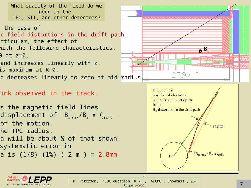
There will be a kink observed in the track.
Ionization follows the magnetic field lines resulting in a displacement of B,max/Bz x ldrift .The sagitta is ½ of the motion. The arm is ½ of the TPC radius.The fitted sagitta will be about ½ of that shown. If B,max=1%, the systematic error in the fitted sagitta is (1/8) (1%) ( 2 m ) = 2.8mm which is huge!
B
Consider the case of magnetic field distortions in the drift path, in particular, the effect of a B with the following characteristics. B=0 at z=0, and increases linearly with z. B is maximum at R=0, and decreases linearly to zero at mid-radius.

D. Peterson, “LDC question TR_7” , ALCPG , Snowmass , 25-August-20058
What quality of the field do we need in the TPC, SIT, and other detectors?
A magnetic field distortion in the drift path, B, with magnitude 1% and particular z and R dependence, creates an error in sagitta of s = 2.8 x 10⁻³ m . The sagitta limit is s < 6 x 10⁻⁶ m.
Thus the field uniformity requirement is B/B < 1% (6 x 10⁻⁶) / (2.8 x 10⁻³) = 2 x 10⁻⁵ .
The field uniformity requirement: a B distortion

D. Peterson, “LDC question TR_7” , ALCPG , Snowmass , 25-August-20059
What quality of the field do we need in the TPC, SIT, and other detectors?
In this case, the sagitta is constant; the cord, L, increases by L= Br,max/Bz x ldrift . For Br,max/Bz=.01, ldrift=2m, L = 2 cm
I will calculate (1/Pt)=2 (1/Pt) L/L with Pt =10 GeV; at lower momenta multiple scattering dominates.
For L=1.7m, (1/Pt) =2 (1/Pt) L/L = .0024/GeV .
BrConsider another case of magnetic field distortions in the drift path, Br with the characteristics, Br=0 at z=0, and increases linearly with z. Br =0 at R=0 and increases linearly with R with a maximum Br,max at z=lTPC and R=RTPC .

D. Peterson, “LDC question TR_7” , ALCPG , Snowmass , 25-August-200510
What quality of the field do we need in the TPC, SIT, and other detectors?
A magnetic field distortion in the drift path, Br, with magnitude 1% and maximum magnitude at maximum z and R, creates a shift in Pt, Pt = 2.4 x 10⁻³ /GeV . The limit is (1/Pt) < 1.6 x 10⁻⁵ /GeV. (the contribution that results in a 5% increase in (1/Pt)
Thus the field uniformity requirement is then B/B < 1% (1.6 x 10⁻⁵) / (2.4 x 10⁻³ ) = 7 x 10⁻⁵ .
The field uniformity requirement: a radial distortion

D. Peterson, “LDC question TR_7” , ALCPG , Snowmass , 25-August-200511
What quality of the field do we need in the TPC, SIT, and other detectors?
The field uniformity requirement, Ron Settles
0 is defined as the residual added fluctuation of the r measurements on the endplate and limited such that the resolution increase is 5%. The value can be simply derived as [ ( (1.05)2 -1 )½ = .32 ] x 100m = 30m .
0 is related to the residual magnetic uncertainty by 0 = Br, / Bz x ldrift .
Thus, for ldrift = 2m, the magnetic field uncertainty is limited by Br, / Bz < 0 / ldrift = 1.5 x 10⁻⁵ .
The above limit is based on the tpc-only resolution;
the limit based on the system resolution is Br, / Bz < 0 / ldrift = 0.4 x 10⁻⁵ .

D. Peterson, “LDC question TR_7” , ALCPG , Snowmass , 25-August-200512
What quality of the field do we need in the TPC, SIT, and other detectors?
The Br result indicates that the tracking system is less sensitive to this model of a distortion.
The results from the B and from the measurement fluctuations are different conditions.
A field uniformity of 1 x 10⁻⁵ would probably be sufficient (without mapping).
A field uniformity of 1 x 10⁻⁵ probably can not be achieved.Systematic uncertainties must be limited to this value. ( And, that brings us to the next question.) All track trajectories must be corrected by a transport fitter. All drift trajectories must be corrected with a map.
from a study of a particular systematic B/Bz < 2 x 10⁻⁵
The field uniformity requirement
from a study of a particular systematic rB/Bz < 7 x 10⁻⁵
from residual measurement fluctuationsB/Bz < .4 x 10-5 (system resolution)

D. Peterson, “LDC question TR_7” , ALCPG , Snowmass , 25-August-200513
How can we measure and monitor the field distortions at the required level of accuracy?
Mapping the magnetic field to an accuracy of B/B < 1 x 10⁻⁵ is a difficult measurement.
The Aleph field map was internally self consistent to 40 x 10-5.
The map measurements are fit to conform with Maxwell’s equations. Differences of the corrected map, with respect to a model of the magnet, are within 40 x 10-5 .
However, the “consistency” is not a direct measure of the accuracy.
The observed Aleph momentum resolution imples that the field map has an accuracy of 0=70m. Thus, a magnetic field uncertainty achieved was B/B = 70mm/30mm x (1.5 x 10-5 ) = 3.5 x 10⁻⁵
We must measure the field map to the best possible accuracy, probably 3.5 x 10⁻⁵. We will require an independent measurement of the field distortions to achieve the required accuracy, 1 x 10⁻⁵ .

D. Peterson, “LDC question TR_7” , ALCPG , Snowmass , 25-August-200514
How can we measure and monitor the field distortions at the required level of accuracy?
There are competing distortions that must be eliminated, or solved simultaneously :
magnetic field distortions affecting the track trajectory,
magnetic field distortions affecting the drift trajectory,
alignment of the TPC to the silicon detectors, and
alignment of the sub-panels of the readout of the TPC.
Some competing distortions must be measured, with 12m (.0005 inch) certainty, independent of the tracks.
(In a drift chamber, the problem of magnetic field distortions of the drift trajectory is replaced by the problem of simultaneously solving the details of the drift function and t0 .)
It would be convenient to measure the magnetic field distortions with the tracks.
It would also be convenient to align the endplate sub-panels with the tracks.Due to correlations, we probably can not do both.

D. Peterson, “LDC question TR_7” , ALCPG , Snowmass , 25-August-200515
How can we measure and monitor the field distortions at the required level of accuracy?
The sub-panels must be aligned to 12m (roughly half of the sagitta uncertainty limit)to separate distortion of the readout from distortion of the drift path in the magnetic field.
To provide alignment of the sub-panels of the TPC readout,the frame must have reference edges defined to 12m.
Coordinate-Measuring-Machines allow (.0005 inch) 12.7m over 1m, (.002 inch) 50m over 4m.
We will be required to find a way to achieve the better resolution over the larger object.
Endplate frame cartoon
Some competing distortions must be measured, with 12m certainty, independent of the tracks.

D. Peterson, “LDC question TR_7” , ALCPG , Snowmass , 25-August-200516
How can we measure and monitor the field distortions at the required level of accuracy?
Extra slide showing CLEO measurements

D. Peterson, “LDC question TR_7” , ALCPG , Snowmass , 25-August-200517
How can we measure and monitor the field distortions at the required level of accuracy?
Magnetic field distortions affecting the drift trajectory
With proper quality control and measurement during manufacture, the TPC readout will be accurate enough to measure the magnetic field distortions.
It will require a set of laser beams. (Not all experience shows they are useful.)
Figures show a possible configuration.Laser beams cross the chamber in a way to provideradial and azimuthal distortion measurements at several longitudinal positions.
Magnetic field measurementsThe field should be mapped with an accuracy of 1 x 10⁻⁴ , with all iron and compensation magnets in place, for a consistency check of the laser measurements.
Magnetic field distortions affecting the track trajectory
The field map can be derived from the drift map.Consistency can be made with tracks.

D. Peterson, “LDC question TR_7” , ALCPG , Snowmass , 25-August-200518
Can control samples be used to improve the knowledge of the field map
The CLEO tracking group uses e+e- and +- events, e+e- when we need higher statistics, +- when we are concerned about the charge asymmetry.
CLEO uses a constrained fit of the two tracks to decouple the tracks from sub-detector mis-alignment. Two tracks, when not constrained, are described by 10 parameters. We require: meet at a point ( 2 constraints), back-to-back in the center-of-mass ( 2 constraints ), equal momentum in the center-of-mass (1 constraint ). The two-track fit has a moment arm of 3.2m, compared to 1.3m in the TPC alone.
Hypothetically, the resolution of a two-track fit, without the VTX or SIT, is (1/pt ) = 4 x 10⁻⁵/GeV, and competitive with single track system resolution.
At LDC, we can also use the tracks to measure magnetic field correction in the drift trajectory if the track trajectory is in a region of high-uniformity magnetic field. ( It may be necessary to use only track trajectories near z=0. )
The two-track fits can also be used to align the VTX and SIT.
See slide 23 for added comments on the field homogeneity requirements near z=0.

D. Peterson, “LDC question TR_7” , ALCPG , Snowmass , 25-August-200519
Can the large distortions in the large crossing angle
be accounted for?
This is a 2% distortion.
The magnetic field of the “DID” must be understood at the level of
1 x 10⁻⁵ / .02 = 5 x 10⁻⁴ (of itself)
Do you intend to say, “large magnetic field distortions associated with the large crossing angle”?
What about the anti-solenoid? Beyond 4m?
The “DID” violates the requirement for high field uniformity within |z| < 50cm.
The “DID” field is .02 Tesla, 5 x 10⁻³ x Bz .
See slide 23 for added comments on the homogeneity requirements near z=0.

D. Peterson, “LDC question TR_7” , ALCPG , Snowmass , 25-August-200520
Can the large distortions in the large crossing angle be accounted for?
The main magnetic field must be measured. One can not rely on finite-element-analysis as the only measurement when there is saturated iron.
~ .5x10-4
variation

D. Peterson, “LDC question TR_7” , ALCPG , Snowmass , 25-August-200521
Does it make sense to eliminate the plug,
at the cost of a shorter magnet and thus a less homogeneous field?
Extent of TPC: 2.7m
Field at 3.8m, length of TPC plus a distance equal to the length of the plug
This changes Bz by only 5%, at the maximum Z. The Br component of < ¼ %. It is all azimuthal independent.
Does it violate the uniformity of < 10-4 close to z=0 , as will be needed for the control sample tracks?
See slide 23 for added comments on homogeneity requirements near z=0.

D. Peterson, “LDC question TR_7” , ALCPG , Snowmass , 25-August-200522
Conclusions
The magnetic field should be measured to an accuracy of 1 x 10⁻⁵ with all compensation magnets and iron in place.
One can not rely on finite element analysis for the measurement of the solenoid field.
To provide an independent measure of the drift trajectory distortion,locate the readout sub-panels to 12 m. Use lasers to measure the distortion of the drift trajectory.
Hypothetically, the resolution of a two-trackfit, without the VTX or SIT, is (1/pt ) = 4 x 10⁻⁵/GeV, and is competitive with single track system resolution.
Two-track fits can be used for consistency checks of the drift trajectory distortion. and for aligning the VRX and SIT.
The magnetic field of the “DID” must be understood at the level of 5 x 10 -4 (of itself) . However, the “DID” contributes significant non-homogeneity near z=0.
Field quality, or uniformity, of 1 x 10⁻⁵ can not be achieved.
Systematic uncertainties must be limited to this precision avoid introducing systematic error into the VTX and SIT alignment.
All track trajectories and drift trajectories must be corrected by mapping or a transport fit.
Removing the plug appears to be a smaller perturbation that the “DID”. But a field uniformity of 10-4 is required near z=0 to for the control sample measurements.
See slide 23 for added comments on homogeneity requirements near z=0.

D. Peterson, “LDC question TR_7” , ALCPG , Snowmass , 25-August-200523
Can control samples be used to improve the knowledge of the field map
Thus, the required field homogeneity is :
B/B = 5 x 10⁻⁵ /GeV x 45 GeV x .2 = 4.5 x 10⁻⁴ .
Field homogeneity required near z =0 , |z| < 50cm
Field homogeneity, not only knowledge, is required near |z|=0 to decouple the distortions of the track trajectory from the distortions of the drift trajectry.
The requirements are less severe because the track trajectory is bent by the field while the drift trajectory follows the field lines.
With a momentum resolution goal: (1/pt ) < 5 x 10⁻⁵/GeV, the magnetic field distortion which would yield a contribution equal to the resolution limit is B/B = Pt/Pt = 5 x 10⁻⁵ / GeV x Pt .
This can be evaluated at the Z pole, Pt=Ebeam = 45 GeV .
We have specified the limit of the the uncertainty of the magnetic field to correspond to a distortion that results in a 5% increase in the resolution when added in quadrature.The resolution increase due to the field homogeneity will add to this and should be limited 2%, when added in quadrature; [ ( (1.02)2 -1 )½ = .2 ].
This slide was added after the conclusion talk, 25-Aug-2005
The required field homogeneity is nearly equal to the stated Aleph field map internal self consistency, 4 x 10 -4 .While the required field homogeneity is an order of magnitude more that the stated Aleph magnetic field uncertainty, 3.5 x 10⁻⁵, the latter is derived from tracks and can not be used as input to a track-based field measurement.

D. Peterson, “LDC question TR_7” , ALCPG , Snowmass , 25-August-200524
Can the large distortions in the large crossing angle
be accounted for?
edge of larger green area is 95% contours are 0.5 % changes
CLEO III (c) has a 1.5 (1.0) Tesla solenoid field with superconducting (and permanent) quadrupole magnets intruding into the tracking volume.
This slide was removed from the 22-Aug-2005 presentation, for the conclusion, 25-Aug-2005.

D. Peterson, “LDC question TR_7” , ALCPG , Snowmass , 25-August-200525
Can the large distortions in the large crossing angle be accounted for?
CLEO uses a calculated magnetic field map of the contribution from the quadrupole to correct for the quadrupole distortions.
The Kalman fit is a transport method and, therefore, inherently allows application of a magnetic field map.
The magnetic field is distorted by the fringe field of the final focus quadrupoles causing a 2-cycle momentum dependence.
This is corrected in the Kalman fit.
(The residual 1-cycle momentum dependence is due to the 2.5 mr crossing angle)
All track trajectories and ionization trajectories must be corrected using a transport type fitter.
This slide was removed from the 22-Aug-2005 presentation, for the conclusion, 25-Aug-2005.