Embed Size (px)
Citation preview

60
65
70
75
90%
RH
80%
RH
70%
RH
60%
RH
50%
RH
40% R
H
30% R
H
20% R
H
10% RH
150
140
130
120
110
100
90
80
70
60
50
40
30
20
10
0
27
28
29
30
31
33
34
35
36
37
38
39
40
41
42
EN
TH
ALPY A
T S
ATU
RATIO
N ( B
TU
/ L
GR
AIN
S O
F M
OIS
TU
RE
PE
R P
OU
ND
OF
DR
Y A
IR
10510095908580757065605550
14.0 CU. FT.13.5 CU. FT.13.0 CU. FT.
21
22
23
24
25
26
32
DRY BULB °F
Desert Aire’s TotalAire™ Series dehumidifiers provide you the most complete solution for your dedicatedoutdoor air system (DOAS) and high outside air system (HOAS) applications. Our many options allow youto design the highest energy saving solution for your compliance to ASHRAE 62.1 code ventilation require-ments for new construction and renovation projects. This system allows the engineer to separate the latentload of the building and deliver conditioned air to the space which will optimize the performance of thebuildings convention heating and cooling systems. Rely on Desert Aire for a solution for your completeoutside air needs.
DEDICATED OUTDOOR AIR SYSTEMS
DOAS and HOAS Equipmentfor 100% Outdoor Air andMixed Air Applications
DOAS and HOAS Equipmentfor 100% Outdoor Air andMixed Air Applications
Educational Environments
Hotels and Motels
Restaurants
Medical Facilities
Office Environments
OPTIMIZING SOLUTIONS THROUGH SUPERIOR DEHUMIDIFICATION TECHOLOGY

ISSUES OF INDOOR AIR QUALITY (IAQ)
Several HVAC trade and professional organizations, including ASHRAE,
have documented the need for suitable indoor air quality. A primary
requirement for maintaining proper IAQ is through the introduction of
varying amounts of outdoor air. The down side of adding outdoor air is
that it also admits excess moisture into the facility. If this condition is
not controlled, it can create an environment for mold, mildew, viruses
and other potentially hazardous organisms to flourish. The key to
preventing mold formation and growth is to control the relative humidity
within the space. A standard air conditioner cannot achieve this since it
controls only temperature. Instead, a system must be implemented
that can provide full control of both temperature and relative humidity.
DEHUMIDIFICATION
All TotalAire™ units are designed around a reliable, efficient dehumidifi-
cation system. There are two main reasons for using the dehumidifier as
a base to build a complete ventilation system:
• Significant additional energy costs will result if the latent cooling
provided by a standard air handler is used for dehumidification.
In contrast, dehumidifiers are the only efficient means to regulate
moisture removal.
• TotalAire™ dehumidifiers are configured for the easy addition
of optional components needed for a complete solution, options
that offer effective solutions that are not otherwise available.
TotalAire™ units are engineered and manufactured for excellent
performance, dependability and serviceability. Specially designed
evaporator coils provide maximum moisture removal. Components
are carefully selected for reliable long-term operation.
DEDICATED OUTDOOR AIR SYSTEMS (DOAS)
The most energy efficient method to remove moisture is through the
use of a dedicated outdoor air system that lowers the dew point tem-
perature of supply air to below 55° F. This also helps remove existing
moisture from inside a facility. A DOAS design can also be optimized to
remove maximum moisture at the lowest electrical consumption rate
(Moisture Removal Efficiency, MRE) at both full and part-load conditions.
Desert Aire manufactures DOAS units under our Aura™, TotalAire™
and VerticalAire™ product lines.
HIGH OUTDOOR AIR SYSTEMS (HOAS)
If the application requires an air handler to accept outside air volumes
of 50% to 100% of the supply air volume, conventional sensible heating
and cooling units cannot be used. The system must be designed
to remove the outdoor air’s moisture, but also incorporate a specialized
sequence of operation to provide the appropriate sensible cooling and
heating. A HOAS design can also be optimized to remove maximum
moisture at the lowest electrical consumption rate (Moisture Removal
Ef f ic iency, MRE) dur ing both fu l l and par t - load condi t ions.
Desert Aire manufactures HOAS units under our Aura™, TotalAire™
and VerticalAire™ product lines..
TOTALAIRE™ INDOOR AIR QUALITY (IAQ)
Figure 1 - Basic Refrigeration Circuit Diagram

DESIGN OPTIONS
Desert Aire’s TotalAire™ Series offers the widest range of performance
options while maintaining its main focus: Meeting the target dewpoint
while attaining the lowest operational cost. In addition, the many options
help to reduce the operating cost of the remainder of the building’s sen-
sible cooling and heating systems. The design engineer has the ability to
configure the system with the following configuration options.
• DOAS or HOAS - System is flexible in the amount of outside air
delivered
• Energy Recovery - An enthalpy wheel can recover energy from the
exhaust air stream
• Control Strategy -Multiple choices allows better energy efficiency
• Choice of Condensers - Air, water or geothermal (or combinations)
• Auxiliary Heating -Many options including:
- Gas
- Electric
- Hot water or Steam Coils
- Geothermal
• Miscellaneous Options - Indoor/Outdoor systems, fan discharge
direction, coated coils and better filtration are just a few of the
many additional configuration options available for inclusion on
the TotalAire™ Series.
CONDENSER DESIGN OPTIONS
Each unit includes a hot gas reheat coil that is integrated into the
refrigeration circuit along with a modulating control system to maintain
the discharge temperature based upon the choice of control algorithm.
This coil reheats the leaving air to the precise temperature required
and rejects any remaining energy to a second condenser.
A choice of secondary condenser options allows the design engineer to
integrate the superior design features of the TotalAire™ system into
any building type or location. The condensing system is selected to
work in series with the hot gas reheat coil to implement the control option of
choice. You may choose either an air-cooled condenser, that dissipates
heat to the outdoors, or a water-cooled heat exchanger, which releases
heat into a facility’s chilled water or cooling tower loop.
Air-cooled condensers may be packaged with the dehumidifier on a single
skid in an outdoor application. A split system allows the dehumidifier to
be located away from the condenser, indoors or outdoors. Desert Aire
only requires two refrigeration pipes (suction and liquid lines) to be run
between the dehumidifier and remote condenser.
An optional water-cooled condenser can also be selected for use in loop
systems, hybrid systems or in geothermal applications.
AIR SEPARATED COILS
If a hot gas reheat coil is installed too close to the evaporator coil,
re-hydration can occur. Water on the surface of the evaporator coil can
be blown onto the hot gas reheat coil. This will convert it back into vapor
which will then be returned to the space. This completely negates all
dehumidification efforts and fails to meet basic IAQ design requirements.
Consequently, the system will remove less moisture at a higher electrical
cost. That’s the reason we design our IAQ units with adequate separation
between the outlet face of the evaporator coil and the inlet face of the hot
gas reheat coil to prevent re-hydration.
For more information visit www.desert-aire.com
Figure 3 - Packaged System
Figure 2 - Water Condenser

410 2019/01
CABINET AND CONSTRUCTION
The TotalAire™ Series features a double wall construction cabinet with
a powder coated galvanneal steel outer wall and a sturdy galvanized inner
panel. Hinged access doors shall allow easy access to internal compo-
nents within each section. Each door shall have a minimum of two cam
latches. Weatherproof compression gaskets shall seal between the door
and unit casing to produce an air tight seal. The unit is designed for
complete access for service and maintenance from one side only.
Outdoor cabinets include a rain hood and isolation dampers with actuator
and have a fully weatherproof roof with a cross broken roof for water
drainage.
FILTRATION
Outdoor air contains many airborne particles and pollutants. Filtration is
essential to prevent dirt from accumulating on coils and contaminating
indoor spaces. When 1-inch or 2-inch wide filters are used, they must be
frequently replaced. Therefore, our IAQ units are equipped with a minimum
of 4-inch, MERV 8, pleated filters to reduce filter maintenance. Optional
prefilters and higher efficiency MERV 13 filters are available as an option.
COIL COATINGS
Sea coast coil coatings are available. Desert Aire uses ElectroFin™ coil
coatings to provide long life in corrosive environments.
Figure 5 - TotalAire™ Electrical Panel DetailFigure 4 - TotalAire™ Filter Rack With MERV 13 Filters Installed.
BUILDING MANAGEMENT INTEGRATION
The unit’s controller has the following BMS choices:
• LonWorks® compatible.
• BACnet™ MSTP compatible.
• BACnet™ Ethernet compatible.
• Modbus® compatible.
COMPLETE SOLUTIONS FOR 100% OUTDOOR AIR
Solving the 100% outdoor air problem is easy with a TotalAire™
dehumidifier and the expertise of a Desert Aire representative. Complete
solutions addressing moisture, cooling and heating loads while recovering
and saving energy will help ensure proper indoor air quality and comfort.
Contact Desert Aire for assistance when you need complete solutions for
conditioning ventilation air.
OPTIMIZING SOLUTIONS THROUGH SUPERIOR DEHUMIDIFICATION TECHNOLOGY
N120 W18485 Friestadt Road, Germantown, WI 53022 sales@deser t-aire.com

LEAVING AIR TEMPERATURE CONTROL OPTIONS
Supply Air Control Strategy
DX-DOAS and DX-HOAS units can use three unique methods to control supply air temperature. The first and simplest
strategy is referred to as Supply Air Temperature Control. This method maintains a constant supply air temperature
(SAT) regardless of the season and space requirements.
However, two other strategies can achieve greater energy efficiency – Zone Reset of Supply Air Temperature Control as
well as Outdoor Air Reset of Supply Air Temperature Control. Both of these methods allow the design engineer to integrate
the loads of the DX-DOAS and the main air handler. Because supply air temperature can be varied by the DX-DOAS,
the main air handler can be downsized to save compressor and fan energy since the latent load is minimized or
eliminated for this sensible cooling system.
Supply Air Temperature Control
In this basic mode, the unit always maintains the supply air setpoint value, regardless of the outdoor or inside room
temperature. This fundamental control allows the outdoor air to be conditioned to a neutral temperature (e.g. 72° F)
in all seasons. The main air handler for the space controls the actual space temperature. This strategy uses a duct-
mounted discharge temperature sensor to provide a feedback signal to the PID controller and maintain a precise SAT
regardless of the conditions of the entering air. The SAT on the system is maintained at ±0.2° F DB when the compressor
is running.
This method enables the DX-DOAS system to deliver neutral air while the main air handler must be sized for the zone’s
full load.
LEAVING AIR TEMPERATURE CONTROL
CONTR
OL STR
ATEG
IES
E/A
CONDITIONED SPACE
PID Control With Reset
HGRD
X
Temp./RH
AUX
Temp. / RH
Outdoor Condenser
O/A
Temp.
Figure 1 - Zone Reset Control Configuration

CONTR
OL STR
ATEG
IES
Zone Reset of Supply Air Temperature Control
This strategy combines a wall-mounted zone sensor with a duct-mounted sensor to provide supplemental sensible
heating or cooling to the conditioned space (see figure 1). The zone sensor completes a feedback loop to the controller
such that the supply air temperature setpoint is adjusted to maintain a targeted zone temperature due to changing
conditions in the zone. When the system’s compressors are energized, the controller will vary the amount of hot gas
being rejected to the reheat coil. In the auxiliary heating mode it varies the auxiliary heating output. The controller
varies the supply air temperature within a fixed range (e.g., 60° to 95° F) to maintain a room’s setpoint (conditional
upon system’s capacity).
In this strategy, the DX-DOAS unit becomes the first stage cooling or heating system with the main air handler
being the second stage. This is best applied if rooms have similar load characteristics. While a DX-DOAS primarily
focuses on dehumidifying and reheating the air, the unit provides a secondary benefit in the cooling mode. Should
the space temperature rise above the setpoint, the system can switch to the cooling mode and reject the resulting
heat to the condenser. Because the DX-DOAS assumes a large portion of the cooling load, the size of the
main air handler can be reduced proportionally to provide second stage cooling.
Feed ForwardControl
E/A
CONDITIONED SPACE
HGRD
X
AUX
Temp. / RH
Outdoor Condenser
O/A
Temp.
Figure 2 - Outdoor Air Reset Control Configuration
Outdoor Air Reset
This strategy uses feed-forward logic in that the controller resets SAT based on the outdoor air temperature.
(See Figure 2.) As outdoor air becomes warmer and more humid, the DX-DOAS will identify that the space needs cooling
and thus lower the SAT of the system. If the outdoor air turns cooler, it will reset the SAT to a warmer temperature.
Four temperature ranges are established. All reset setpoints are adjustable between 60° and 95° F, but cannot overlap.
410-a 2019/01
OPTIMIZING SOLUTIONS THROUGH SUPERIOR DEHUMIDIFICATION TECHNOLOGY
N120 W18485 Friestadt Road, Germantown, WI 53022 sales@deser t-aire.com

HEAT PUMP AUXILIARY HEATING OPTION
DEH
UMID
IFIC
ATIO
N M
ODE O
F OPE
RAT
ION
Q-PUMP PROVIDES HIGHEST COP
Q-PUMP™- 100% OUTDOOR AIR SYSTEM
Desert Aire’s Q-Pump™ system (protected by patent #6,666,040 and an additional patent applied) uses a four-element
refrigeration system to overcome the typical problems of a two-element reverse cycle system, including:
1.) Reduced efficiency and performance.
2.) High cost of oversized refrigeration valves.
3.) Potential for liquid slugging and need for accumulators.
4.) Refrigerant suddenly flashing into vapor, violently expanding and damaging pipes.
Desert Aire’s Q-Pump™ dehumidifier uses a unique method of heating 100% outdoor winter air without the need for a
separate auxiliary heat source such as a gas furnace. The system utilizes an Electronic Expansion Valve (EXV) to insure
the best performance and operation at low outside air temperatures while reducing the set-up time. At typical airflows
for DOAS, our basic system is effective down to 0°F winter design temperature. With an optional enthalpy wheel, the
system is effective down to minus10°F.
The key difference between
Desert Aire’s Q-Pump™ op-
tion and prior solutions is the
use of two independent water
condensers. One acts as the
true condenser for the balance
of the total heat of rejection
(THR) of the system and the
other is the evaporator in the
reverse cycle heating mode.
The Q-Pump™ is easily incorporated into Desert Aire’s TotalAire™ systems by adding one water exchanger. The hot gas
reheat coil typically rejects 75% of the THR. The remaining energy is rejected to the water condenser which raises the
ground source water loop by 2.5° - 3°F. This added energy to the water loop increases the system’s efficiency. In the
summer mode the water evaporator is inactive and removed from the refrigeration loop by a solenoid valve. In the winter,
the air evaporator coil is inactive and the water evaporator will pull energy from the slightly heated ground water loop.
The evaporator reduces the water temperature by 5°to 6°F. Figures 7 and 8 provide a detailed schematic of
our Q-Pump™ system and also show how it functions in the summer and winter modes.
A second unique feature to Desert Aire’s Q-Pump™ is its sophisticated control logic that automatically adjusts the
systems condensing temperature to allow the system to have enough heat on cold winter days to meet the desired
leaving air temperatures. Without enthalpy wheels, conventional heat pumps turn off at entering temperatures below
40°F and must utilize auxiliary heating devices to heat the air. During this operating period, these devices have COP’s
less than 1.0. Desert Aire’s Q-Pump™ uses the following sequence to eliminate this problem:
GROUND LOOP (HYBRID)
BUILDINGS
COOLING TOWER
BOILER
Figure 1 - Hybrid Loop with Boiler and Cooling Tower

HEA
TING M
ODE OF OPE
RAT
ION
• First stage is to adjust the Electronic Modu-
lating Valves (EMV1) valves to regulate the
amount of hot gas to the hot gas reheat coil.
This controls the air temperature while keeping
power consumption low. COP for this mode
will generally fall between 3.5 and 4.0.
• Second stage is to adjust the EMV2 valve that
regulates the systems condensing temper-
ature. Raising the condensing temperature
increases the heating capacity of the system,
but this increases the electrical energy
consumed so at the coldest entering air
temperature (e.g. 0°F), the COP would be
reduced slightly to approximately 3.0.
CONCLUSION
If feasible, the installation of a heat pump into an
HVAC application provides many advantages.
First and foremost, this type of system provides
such an efficient exchange of energy that a facility
can expect an average of 50% savings in heating
and cooling bills with respect to the 100% outside
air dehumidifier.
While the concept of a heat pump is simple, the
application requires precise, flawless engineering.
Because Desert Aire's TotalAire™ dehumidifiers
are specifically designed for energy recovery, a
Q-Pump™ can be easily incorporated into the
system. Desert Aire’s Q-Pump™ provides these
unique benefits:
• Lowest operating cost by utilizing
dedicated evaporators for the dehumidification and heat extraction
• Control of heating set-points at the lowest entering air conditions
• Automatic adjustment of system set-up using electronic expansion valve
Contact your local Desert Aire representative if you would like more information or assistance about incorporating
a TotalAire™ dehumidifier and heat pump into your HVAC system.
EXACT LAT75° FDB
COMPRESSOR
HOT GASREHEAT
WATERCONDENSER
EVAPORATOR
WATERCHILLER57° F
WATER OUT
60° FWATER IN
65° F WATER
40° F EAT
(PART LOAD)
EVAPORATOR(INACTIVE)
RECEIVER
COLDWINTER AIR
EXV
Figure 3 - Q-Pump Schematic with LAT Control: Heating Mode
EXACT LAT75° FDB @ 50% RH
COMPRESSOR
HOT GASREHEAT
WATERCONDENSER
EVAPORATOR
WATERCHILLER100° F
WATER OUT
90° FWATER IN
100° F WATER
55° F LAPD
EXV(INACTIVE)
RECEIVER
WARMHUMID AIR
95° FDB @ 78° FWB
Figure 2 - Q-Pump Schematic with LAT Control: Cooling Mode
410-b 2019/01
OPTIMIZING SOLUTIONS THROUGH SUPERIOR DEHUMIDIFICATION TECHNOLOGY
N120 W18485 Friestadt Road, Germantown, WI 53022 sales@deser t-aire.com

AUXILIARY ELECTRIC HEAT
ELEC
TRIC
HEA
TOPTIONAL AUXILIARY ELECTRIC HEATING OPTIONS
Desert Aire provides auxiliary electric heating options for the TotalAire™ Series that are sized to meet the winter
heating requirements of the outside air.
These heating elements are utilized when the outside air temperature for a DOAS unit or mixed air temperature for a
HOAS unit drops below the low economizer set point. The heaters are not allowed to operate when the unit is in the
cooling or dehumidification mode.
Desert Aire sizes the heating elements to precisely match the load requirement of the system. The heaters are
automatically controlled by the units microprocessor to maintain an exact leaving air temperature. An SCR controller is
used for the electric heat option to vary the heat output.
Design Specifications
The following list highlights the noteworthy fea-
tures of the TotalAire™ Series electric heaters:
• System Single Point Power to Dehumidifier
• NiCr 60 Corrosion-Resistant Element
• Welded Construction Using 20 MSG
Galvanized Steel
• Automatic Reset High Temperature Limit
Safety Switch
• Manual Reset High Maximum Temperature
Limit Safety Switch
• Air Flow Pressure Switch
• Fusing as Required for Each 48 Amp
Circuit
• Fused Circuits per N.E.C., UL, and CSA
Figure 1 - Detail of Electric Heating Element for TotalAire™ Series Unit
410-c 2019/01
OPTIMIZING SOLUTIONS THROUGH SUPERIOR DEHUMIDIFICATION TECHNOLOGY
N120 W18485 Friestadt Road, Germantown, WI 53022 sales@deser t-aire.com

AUXILIARY GAS HEATING OPTION
AUXILIAR
Y GAS
HEA
TMULTIPLE GAS HEATING OPTIONS
Desert Aire provides multiple gas heater options for its TotalAire™ Series product line that are sized to meet the
winter heating requirements of the outside air. Both natural gas and LP gas burner options are available. These
heating elements are utilized when the outside air temperature for a DOAS unit or mixed air temperature for a
HOAS unit drops below the low economizer set point. The heaters are not allowed to operate when the unit is in the
cooling or dehumidification mode.
Desert Aire combines different burner sizes to precisely match the load of the system. This may be in a single heater
module or in multiple modules. A modulating gas valve is automatically controlled by the unit’s microprocessor to
maintain an exact leaving air temperature. If multiple burner sets are utilized, then a veneer sequence is used where
the base burner is modulated and the others are staged. The system’s overall turn down ratio is a function of the number
of heating modules and is summarized in the table below:
Quantity Heaters
1
2
3
Tons
2 to 30 tons
20 to 30 tons
40 to 60 tons
Turndown RatioNatural Gas
4 to 1
8 to 1
12 to 1
Turndown RatioLP Gas
2 to 1
4 to 1
6 to 1
Figure 1 - Detail of Gas Heat Compartment on TotalAire™ Series Unit
410-d 2019/01
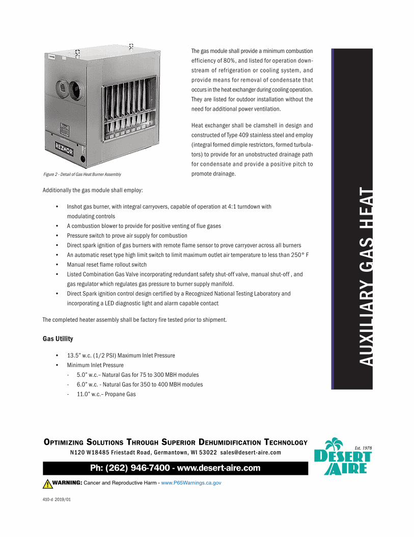
The gas module shall provide a minimum combustion
efficiency of 80%, and listed for operation down-
stream of refrigeration or cooling system, and
provide means for removal of condensate that
occurs in the heat exchanger during cooling operation.
They are listed for outdoor installation without the
need for additional power ventilation.
Heat exchanger shall be clamshell in design and
constructed of Type 409 stainless steel and employ
(integral formed dimple restrictors, formed turbula-
tors) to provide for an unobstructed drainage path
for condensate and provide a positive pitch to
promote drainage.
Additionally the gas module shall employ:
• Inshot gas burner, with integral carryovers, capable of operation at 4:1 turndown with
modulating controls
• A combustion blower to provide for positive venting of flue gases
• Pressure switch to prove air supply for combustion
• Direct spark ignition of gas burners with remote flame sensor to prove carryover across all burners
• An automatic reset type high limit switch to limit maximum outlet air temperature to less than 250° F
• Manual reset flame rollout switch
• Listed Combination Gas Valve incorporating redundant safety shut-off valve, manual shut-off , and
gas regulator which regulates gas pressure to burner supply manifold.
• Direct Spark ignition control design certified by a Recognized National Testing Laboratory and
incorporating a LED diagnostic light and alarm capable contact
The completed heater assembly shall be factory fire tested prior to shipment.
Gas Utility
• 13.5” w.c. (1/2 PSI) Maximum Inlet Pressure
• Minimum Inlet Pressure
- 5.0” w.c.– Natural Gas for 75 to 300 MBH modules
- 6.0” w.c. - Natural Gas for 350 to 400 MBH modules
- 11.0” w.c.– Propane Gas
AUXILIAR
Y GAS
HEA
T
Figure 2 - Detail of Gas Heat Burner Assembly
OPTIMIZING SOLUTIONS THROUGH SUPERIOR DEHUMIDIFICATION TECHNOLOGY
N120 W18485 Friestadt Road, Germantown, WI 53022 sales@deser t-aire.com

ENERGY RECOVERY OPTION
ENER
GY REC
OVE
RY WHEE
LENTHALPY WHEEL = ENERGY COST SAVINGS
Desert Aire’s enthalpy wheel recovers a significant amount of energy from exhaust air. This wheel is a rotary counter
flow air-to-air device that transfers both sensible and latent heat between air streams. Filtered outdoor air encoun-
ters the upper half of the wheel while filtered exhaust air flows through the lower half of the wheel. As the wheel constantly
rotates during ventilation, it recovers valuable energy. Except for its rotation, the wheel is a passive device. Its function
basically reverses between summer and winter. Figure 2 on page 2 shows the differences. For more information,
read Desert Aire’s Technical Bulletin 19 -Energy Recovery Wheel Technology.
Deser t Aire’s wheels contain a patented
molecular sieve coating that selectively
adsorbs and desorbs water molecules in
the air. This thin molecular sieve coating
permanently adheres onto a sea water
resistant aluminum alloyed that is composed
of wave and flat, continuously wound layers to
guarantee laminar flow and low static pressure
loss. The wheel matrix, or its total mass,
provides for highly effective sensible and latent
energy exchange.
Most other media will have the desiccant
coated, bonded or synthesized onto the matrix.
The desiccant mater ial must usually be
applied as a thick coating layer that is subject
to delaminate or erode off the media through
the normal life expectancy of the wheel. In
contrast, the desiccant on Desert Aire's media
is designed to permanently adhere to the
surface of the aluminum alloy.
Our design offers excellent face flatness to minimize wear of the inner seal surfaces and reduce cross leakage
while offering a minimum life expectancy of 15 years. Our wheel frames are constructed of evenly spaced
spokes, a galvanized steel band and an aluminum center hub. Frame component sizes and number of parts
vary with wheel size.
We use a fractional horsepower AC drive motor and a durable multilink drive belt as our standard drive system.
It is not uncommon for frost to develop on the wheel under extremely cold winter conditions. The wheel can cool
down to below 32°F and will then freeze moisture from the exhaust stream. Frost may reduce the airflow, but it
will not damage the wheel.
Figure 1 - Enthalpy Wheel Installed in a Desert Aire Aura™ Unit

MODES
OF OPE
RAT
ION
Summertime Operation
In summer, ventilation air transfers its heat to the mass of the wheel. When the wheel turns into the exhaust air
stream, it releases its heat. This significantly cools ventilation air even before it reaches the evaporation coil.
But the wheel also assists with dehumidification. Its media is impregnated with a water-selective desiccant (4Å
molecular sieve) that captures moisture from outdoor air. When the wheel turns into the flow of drier exhaust air,
moisture is released. This reduces the moisture load on the dehumidification coil.
Wintertime Operation
In winter, sensible heat is transferred from warm exhaust air to cooler ventilation air. This heat transfer works in
reverse to that of summer because the exhaust air is much warmer than the incoming air from outdoors.
The transfer of moisture is also reversed. The wheel recovers moisture from the exhaust air and deposits it into the
dry, cold incoming air.SUMMER
WINTER
S/A1000 CFM75°F DB54°F DP50% RH
R/A78°F DB55% RH
Aux. Heating(Inactive)
Reheat CoilEvap. Coil
Energy Recovery Wheel85% Sensible Effectiveness
78% Latent Effectiveness80% Overall
Energy Recovery Wheel85% Sensible Effectiveness
78% Latent Effectiveness82% Overall
R/A75°F DB50% RH
Aux. HeatingReheat Coil(Inactive)
Evap. Coil(Inactive)
S/A1000 CFM75°F DB49°F DP52% RH
E/A1000 CFM28°F DB94% RH
O/A20°F DB16°F WB50% RH
OffWheel
66°F DB56°F WB
OffEvap.
54°F DB53°F WB
OffWheel
77°F DB67°F WB
E/A1000 CFM86°F DB64% RH
O/A88°F DB79°F WB68% RH
Figure 2 - Energy Recovery Wheel Operation
Reduced Loads
The energy recovered by the wheel significantly reduces sensible heating and cooling loads. Likewise, the load on
the refrigerant dehumidification system is also reduced allowing you to use a smaller TotalAire™ dehumidifier.
While the wheel cannot meet the full moisture load alone, it can greatly reduce peak loads on the dehumidifier,
especially when there is a large difference in moisture content between the air streams. Dehumidification through
refrigeration is a standard industry approach.
However, integrating an energy recovery wheel into this type of system allows the dehumidifier to work more effi-
ciently. The wheel significantly decreases the dehumidifier size required to ensure a complete year-round solution.
Its impact is so great that it reduces the required compressor capacity by approximately half.
410-e 2019/01
OPTIMIZING SOLUTIONS THROUGH SUPERIOR DEHUMIDIFICATION TECHNOLOGY
N120 W18485 Friestadt Road, Germantown, WI 53022 sales@deser t-aire.com

DEMAND CONTROL OPTIONS SAVE ENERGY
Night Setback Strategy
During the unoccupied mode, the night
setback strategy is too close the outdoor air
damper and turn off the blower to save
energy. However, in some humid environ-
ments, there is still a high infiltration rate
of moist outdoor air into buildings during
unoccupied times creating excessive
humidity levels.
In these instances, it is desired to add a
recirculation damper to the system and turn
on the blower and compressors to remove
the unwanted moisture during unoccupied times. Desert Aire has two system configurations that provide night setback.
This capability is available on Desert Aire’s TotalAire™ series by adding our enthalpy wheel option and an internal
mixing damper. The Zone Reset of Supply Air Temperature Control package must be ordered to receive the zone sensors.
CO2 Control Strategy
As engineers continue to meet ASHRAE 62 ventilation code air flow rates, they also are trying to minimize energy costs
where ASHRAE 90.1, LEED programs, GSA P100, or other codes and standards are required. Using additional
sophistication in the controls can be an excellent way to minimize energy cost while maintaining proper indoor air
quality and building pressurization.
The Vent i la t ion Rate p rocedure o f ASHRAE 62 is a prescriptive procedure that indicates the outdoor air intake
flow rate based on the level and type of occupancy as well as the floor area. The Ventilation Rate procedure allows for
a dynamic reset of the outdoor air intake flow as operating conditions change. Although the floor area in any building
is fixed, the level and type of occupancy may change from day to day or even throughout a single day.
One of the most effective methods of dynamically changing the flow rate based on occupancy is the utilization of CO2sensors. Although expected concentrations of CO2 are not considered a direct contaminant, it is an excellent measurable
“tracer gas” that indicates the number of occupants present and their activity level. CO2 sensors are also relatively
inexpensive and durable devices.
Desert Aire TotalAire™ units can be ordered with a CO2 control strategy that optimizes the energy efficiency by providing
an optimized level of outdoor air at all times. The addition of two CO2 sensors and variable frequency drives work together
to maintain constant total system air flow by recirculating zone air and introducing varying outdoor air flow rates.
RECIRCULATION OPTIONS
NIG
HTT
IME S
ETBAC
K
S/AHGRD
X
O/AOFF R/A
Figure 1 - Diagram of a TotalAire™ Series unit with a wheel in night setback mode.

CO2 M
ODULA
TION C
ONTR
OL
Since the zone floor area and the rate required for the floor area are fixed in any one application, the TotalAire™ unit
can be programmed with a minimum outdoor air flow rate to account for this. When a change in CO2 is sensed due
to occupants entering or exiting the breathing zone, the outdoor air dampers account for this change in occupancy.
The outdoor air flow rate will vary between the minimum flow rate programmed and 100% outdoor air as needed, always
optimizing the indoor air quality and energy use.
The return air is used to maintain the supply air flow rate while the outdoor air flow rate varies. The constant supply air
flow rate ensures that the duct system operates as intended. It also ensures that diffusers are able to deliver ventilation
air at the correct velocity so that it reaches the breathing zone at all times as required by ASHRAE 62.1.
Desert Aire’s basic CO2 strategy incorporates one indoor CO2 sensor and one outdoor CO2 sensor. The controller
calculates the differential CO2 level (ppm) between the indoor and outdoor signals and then uses this value to properly
adjust both the outdoor ventilation air and the bypass return air to deliver a constant volume to the space.
For applications that require the same
Desert Aire unit to monitor multiple indoor
CO2 sensors, we suggest working with the
project’s engineer to determine the best
method to process these multiple signals
into a final, single indoor CO2 level for the
unit to use in the differential calculation.
This would be an average of all CO2 sen-
sors in the space, or using the signal from
the one indoor CO2 sensor detecting the
greatest concentration of CO2. In any
event, the Desert Aire controller will only
accept a single input for the indoor CO2level and a single input for the outdoor
CO2 level to calculate a final CO2 differ-
ential value. The controller then uses this
differential value to modulate the outside air damper and the bypass damper positions in order to provide adequate
ventilation and maintain a constant supply air volume to the space.
Furthermore, using a differential calculation eliminates errors in estimating the natural background levels of CO2 and
changes in the levels in urban areas. Also, when sensor drift does occur, the sensors tend to drift in a similar fashion.
Calculating a differential helps to ensure accuracy between calibrations. Desert Aire equipment includes a control loop
that further optimizes the outdoor air flow rate by controlling to a specific concentration of CO2 differential through the
use of a PID (proportional/integral/derivative) control loop. In contrast to many other controls for CO2 which have
proportional only control and introduce more air than required during partial occupancy, the TotalAire™ unit further
optimizes energy efficiency by closely maintaining the correct outdoor air flow rate required at any time for any given
occupancy.
Since these applications must bring return air back to the unit, it is most beneficial to use an enthalpy wheel to reduce
energy consumption.
HGRD
X
E/A Fan VFD(∆P across Wheel)
R/A
S/A Fan VFD(∆P across HGR)
OSA Damper(∆P across Wheel)
O/A CO2
Sensor
Space CO2
Sensor
Figure 2 - VFD Control of Fans Using Pressure Sensors

Zone CO2 > Setpoint (Occupied)
The bypass damper modulates closed and the outdoor air damper modulates open. This continues until the zone CO2setpoint is met or 100% outdoor air is introduced. The supply air blower VFD adjusts to an established pressure differ-
ential across the hot gas reheat coil. The pressure drop corresponds to the design supply air volume. Also, the exhaust
air blower VFD adjusts to an established pressure differential setpoint across the wheel’s exhaust air side to maintain
design exhaust air volume. Please note that the supply and exhaust air volumes can be different to maintain a design
positive pressure in the space.
Zone CO2 < Setpoint (Occupied)
The bypass damper modulates open and the outdoor air damper modulates closed. This continues until the zone
CO2 setpoint is met or the minimum outdoor air flow rate is sensed. The supply air blower VFD will adjust to maintain
the same pressure differential setpoint across the hot gas reheat coil to maintain the specified supply air volume.
The exhaust air blower VFD will adjust to a new pressure differential setpoint across the wheel to meet the exhaust air
volume.
Unoccupied Time
During unoccupied times, the system can be turned off or enter the night setback mode where the outdoor air is off,
the mixing damper opens and the unit controls the humidity within the space based on the standard sequence described
in the previous section.
CO2 M
ODULA
TION C
ONTR
OL
410-f 2019/01
OPTIMIZING SOLUTIONS THROUGH SUPERIOR DEHUMIDIFICATION TECHNOLOGY
N120 W18485 Friestadt Road, Germantown, WI 53022 sales@deser t-aire.com

AUXILIARY HOT WATER HEAT
HOT WAT
ERHEA
TOPTIONAL HOT WATER HEATING OPTIONS
Desert Aire provides auxiliary heating options for its TotalAire™ Series product line that are sized to meet the winterheating requirements of the outside air.
These heating elements are utilized when the outside air temperature for a DOAS unit or mixed air temperature for aHOAS unit drops below the low economizer set point. The heaters are not allowed to operate when the unit is in thecooling or dehumidification mode. Desert Aire sizes the heating elements to precisely match the load requirement ofthe system. The heaters are automatically controlled by the unit’s microprocessor to maintain an exact leaving airtemperature. A customer supplied hot water control valve is modulated from the controller with a 0 to 10 VDC directacting signal. Please refer to figure 1 for a typical installation.
HWC Design Inputs
The coil is selected for each customer’s particular application based on the following criteria:
· Entering water temperature (EWT), typically between 140° F and 180° F· Leaving water temperature (LWT), typically 20 degrees less than the EWT· MBH capacity desired· Entering air temperature (EAT), winter design for your area· Leaving air temperature (LAT), typically neutral to a maximum of 100° F· GPM flow rate desired· If there are fluid pressure drop restrictions to be aware of.· Type and concentration of glycol used
For freeze protection Desert Aire uses a capillary type temperature sensor which is attached across the downstreamface of the coil. Freezestat is set at 38 deg F with an auto reset switch. If engaged the unit controls would respond byclosing the outdoor air damper, open the return air damper (if applicable), de-energize the fan, open the hot water coilvalve 100%, and log the alarm on the controller.
To size the control valve, pleaseprovide a qualified vendor the watertemperature, flow rate (gpm) and therequirement for a 0 to 10VDC signal and they will select the appropriatevalve to purchase.
Optional ElectroFin coil coating forsea coast construction is available.
Figure 1 - Hot Water Piping Detail
410-g 2019/01
OPTIMIZING SOLUTIONS THROUGH SUPERIOR DEHUMIDIFICATION TECHNOLOGY
N120 W18485 Friestadt Road, Germantown, WI 53022 sales@deser t-aire.com

BASIC FLOW CONTRL PACKAGE
NO CONTR
OL VA
LVE OPT
ION
Package Components
• Y-Ball Strainer (20 Mesh)
• Automatic balancing control valve
• Blowdown valve
• PT plugs on inlet / outlet
Maintaining proper, constant flow through water-source heat pump equipment optimizes efficiency and capacity.
In today’s larger, dynamic loops that include many valves, branches, and variable speed pumps, maintaining this
constant flow can be challenging. A simple ball valve or circuit setter may not be sufficient to regulate the flow in these
situations. The result may be lower efficiency, nuisance alarm trips, or even possible long-term equipment damage.
Desert Aire has selected Hays Fluid Controls as its partner for its flow regulation control package vendor because of
the importance of maintaining precise flow through our Q-Pump. These flow control packages dynamically regulate
water flow during changing conditions to allow the heat pumps to achieve the highest energy efficiency in both heating
and cooling while eliminating the nuisance alarms so typical of unregulated loop piping systems.
The Hays Mesurflo™ flow regulation valve provides a constant flow rate over a wide range of pressure differentials
(2 to 80 psid). As the pressure drop increases, the rubber diaphragm will flex into the contoured orifice plate to decrease
the flow path. Both the rubber diaphragm and the contoured orifice plate are rigidly controlled to provide a constant
flow rate. The “flexing” action of the rubber diaphragm against the fixed orifice plate makes the Mesurflo™ difficult to
clog and resistant to cavitation damage.
The Hays Mesurflo™ is a constant flow rate device. Since it is a variable orifice that changes to govern the flow, it cannot
be described with the Cv or a pressure drop at a given flow for piping systems design purposes. The designer may
assume a constant flow rate over the differential pressure.
The control packages simplify the selection and installation of the piping system. Each component in the package has
been predefined to work with the corresponding Desert Aire system. All of the rcommended accessories for typical
loops are included in the package. The packages for models QS 02 through 15 further reduces installation time by
including a flexible hose with NPT unit connections. The control package and equipping the unit with optional NPT
connections allows for quick, leak-free connections, vibration isolation, and fewer issues with misalignment.
PT
Return
PT
Supply

PACKAG
E SPE
CIFIC
ATIO
NS
Standard Features of Package
• Operating range 32°F to 225°F• ± 10% flow accuracy• Valve body suitable for 400 psig• Pipe Type
- 15 ton and less – 24 inch Flexible Hose Kits provided by Desert Aire- 20 ton and larger – Hard pipe provided by others
• Extended Pressure / Temperature Ports• Material Specifications
- Ball – chrome plated brass- P/T ports – brass- O-rings – EPDM- Orifice – Polyphenylsulfone
Package Specifications
Tons
02
03
05
08
10
15
DA Part #
DFQ02FN
DFQ03FN
DFQ05FN
DFQ08FN
DFQ10FN
DFQ15FN
GPM
7
11
19
26
34
49
Main(In. FNPT)
3/4”
3/4”
1”
1-1/4”
1-1/4”
1-1/2”
Q-Pump(In. MNPT)
3/4”
3/4”
1”
1-1/4”
1-1/4”
1-1/2”
Valve Body
Brass
Brass
Brass
Gray Iron
Gray Iron
Gray Iron
Connection Type
Flex Hose
Flex Hose
Flex Hose
Flex Hose
Flex Hose
Flex Hose
Connection Size
Tons
20
25
30
36
40
46
50
DA Part #
DFQ20PN
DFQ25PN
DFQ30PN
DFQ36PN
DFQ40PN
DFQ46PN
DFQ50PN
GPM
69
84
102
118
137
153
168
Main(In. FNPT)
2-1/2”
2-1/2”
2-1/2”
2-1/2”
3”
3”
3”
Q-Pump(In. MNPT)
2-1/2”
2-1/2”
2-1/2”
2-1/2”
3”
3”
3”
Valve Body
Ductile Iron
Ductile Iron
Ductile Iron
Ductile Iron
Ductile Iron
Ductile Iron
Ductile Iron
Connection Type
Hard Pipe
Hard Pipe
Hard Pipe
Hard Pipe
Hard Pipe
Hard Pipe
Hard Pipe
Connection Size
Tons
56
60
DA Part #
DFQ56PN
DFQ60PN
GPM
186
203
Main(In. FLGT)
4”
4”
Q-Pump(In. FLGT)
4”
4”
Valve Body
Carbon Steel
Carbon Steel
Connection Type
Flanged
Flanged
Connection Size
Q-Pump is a U. S. Registered trademark of Desert Aire Corp. and Mesurflo is a Registered trademark of Hays Fluid Controls. The automatic balancing valves are protected by U. S. Patent 6,311,712
410-h 2019/01
OPTIMIZING SOLUTIONS THROUGH SUPERIOR DEHUMIDIFICATION TECHNOLOGY
N120 W18485 Friestadt Road, Germantown, WI 53022 sales@deser t-aire.com

2-WAY FLOW CONTROL PACKAGE
2-W
AY FLO
W CONTR
OL PA
CKAG
E OPT
ION
Package Components
• Y-Ball Strainer (20 Mesh)
• Automatic balancing control valve
• Blowdown valve
• Automatic 2-way control valve w/actuator
- Transformer and signal from Q-Pump
• PT plugs on inlet / outlet
Maintaining proper, constant flow through water-source heat pump equipment optimizes efficiency and capacity.
In today’s larger, dynamic loops that include many valves, branches, and variable speed pumps, maintaining this
constant flow can be challenging. A simple ball valve or circuit setter may not be sufficient to regulate the flow in these
situations. The result may be lower efficiency, nuisance alarm trips, or even possible long-term equipment damage.
Desert Aire has selected Hays Fluid Controls as its partner for its flow regulation control package vendor because of
the importance of maintaining precise flow through our Q-Pump. These flow control packages dynamically regulate
water flow during changing conditions to allow the heat pumps to achieve the highest energy efficiency in both heating
and cooling while eliminating the nuisance alarms so typical of unregulated loop piping systems.
The Hays Mesurflo™ flow regulation valve provides a constant flow rate over a wide range of pressure differentials
(2 to 80 psid). As the pressure drop increases, the rubber diaphragm will flex into the contoured orifice plate to decrease
the flow path. Both the rubber diaphragm and the contoured orifice plate are rigidly controlled to provide a constant
flow rate. The “flexing” action of the rubber diaphragm against the fixed orifice plate makes the Mesurflo™ difficult to
clog and resistant to cavitation damage.
The Hays Mesurflo™ is a constant flow rate device. Since it is a variable orifice that changes to govern the flow, it cannot
be described with the Cv or a pressure drop at a given flow for piping systems design purposes. The designer may
assume a constant flow rate over the differential pressure.
The two way flow package includes an integral actuator to terminate the flow to the Q-Pump™ when the DOAS system
is commanded to the unoccupied mode for those water loops with variable speed drives on the water pumps.
The control packages simplify the selection and installation of the piping system. Each component in the package has
been predefined to work with the corresponding Desert Aire system. All of the rcommended accessories for typical
loops are included in the package. The packages for models QS 02 through 15 further reduces installation time by
including a flexible hose with NPT unit connections. The control package and equipping the unit with optional NPT
connections allows for quick, leak-free connections, vibration isolation, and fewer issues with misalignment.
PT
ReturnM
PT
Supply
P

PACKAG
E SPE
CIFIC
ATIO
NS
Standard Features of Package
• Operating range 32°F to 225°F
• ± 10% flow accuracy
• Valve body suitable for 400 psig
• Pipe Type
- 15 ton and less – 24 inch Flexible Hose Kits
provided by Desert Aire
- 20 ton and larger – Hard pipe provided
by others
• Extended Pressure / Temperature Ports
Package Specifications
Tons
02
03
05
08
10
15
DA Part #
DFQ02FD
DFQ03FD
DFQ05FD
DFQ08FD
DFQ10FD
DFQ15FD
GPM
7
11
19
26
34
49
Main(In. FNPT)
3/4”
3/4”
1”
1-1/4”
1-1/4”
1-1/2”
Q-Pump(In. MNPT)
3/4”
3/4”
1”
1-1/4”
1-1/4”
1-1/2”
Valve Body
Brass
Brass
Brass
Gray Iron
Gray Iron
Gray Iron
Connection Type
Flex Hose
Flex Hose
Flex Hose
Flex Hose
Flex Hose
Flex Hose
Connection Size
Tons
20
25
30
36
40
46
50
DA Part #
DFQ20PD
DFQ25PD
DFQ30PD
DFQ36PD
DFQ40PD
DFQ46PD
DFQ50PD
GPM
69
84
102
118
137
153
168
Main(In. FNPT)
2-1/2”
2-1/2”
2-1/2”
2-1/2”
3”
3”
3”
Q-Pump(In. MNPT)
2-1/2”
2-1/2”
2-1/2”
2-1/2”
3”
3”
3”
Valve Body
Ductile Iron
Ductile Iron
Ductile Iron
Ductile Iron
Ductile Iron
Ductile Iron
Ductile Iron
Connection Type
Hard Pipe
Hard Pipe
Hard Pipe
Hard Pipe
Hard Pipe
Hard Pipe
Hard Pipe
Connection Size
Tons
56
60
DA Part #
DFQ56PD
DFQ60PD
GPM
186
203
Main(In. FLGT)
4”
4”
Q-Pump(In. FLGT)
4”
4”
Valve Body
Carbon Steel
Carbon Steel
Connection Type
Flanged
Flanged
Connection Size
Q-Pump is a U. S. Registered trademark of Desert Aire Corp. and Mesurflo is a Registered trademark of Hays Fluid Controls. The automatic balancing valves are protected by U. S. Patent 6,311,712
410-j 2019/01
• Material Specifications
- Ball – chrome plated brass
- P/T ports – brass
- O-rings – EPDM
- Orifice – Polyphenylsulfone
• Actuator
- 24VAC
- 2 position
- Manual operating lever / position indicator
- Location - NEMA 2. IEC IP31
OPTIMIZING SOLUTIONS THROUGH SUPERIOR DEHUMIDIFICATION TECHNOLOGY
N120 W18485 Friestadt Road, Germantown, WI 53022 sales@deser t-aire.com

3-WAY FLOW CONTROL PACKAGE
3-W
AY FLO
W CONTR
OL PA
CKAG
E OPT
ION
Package Components
• Y-Ball Strainer (20 Mesh)
• Automatic balancing control valve
• Blowdown valve
• Automatic 3-way control valve w/actuator
- Transformer and signal from Q-Pump
• PT plugs on inlet / outlet
Maintaining proper, constant flow through water-source heat pump equipment optimizes efficiency and capacity.
In today’s larger, dynamic loops that include many valves, branches, and variable speed pumps, maintaining this
constant flow can be challenging. A simple ball valve or circuit setter may not be sufficient to regulate the flow in these
situations. The result may be lower efficiency, nuisance alarm trips, or even possible long-term equipment damage.
Desert Aire has selected Hays Fluid Controls as its partner for its flow regulation control package vendor because of
the importance of maintaining precise flow through our Q-Pump. These flow control packages dynamically regulate
water flow during changing conditions to allow the heat pumps to achieve the highest energy efficiency in both heating
and cooling while eliminating the nuisance alarms so typical of unregulated loop piping systems.
The Hays Mesurflo™ flow regulation valve provides a constant flow rate over a wide range of pressure differentials
(2 to 80 psid). As the pressure drop increases, the rubber diaphragm will flex into the contoured orifice plate to decrease
the flow path. Both the rubber diaphragm and the contoured orifice plate are rigidly controlled to provide a constant
flow rate. The “flexing” action of the rubber diaphragm against the fixed orifice plate makes the Mesurflo™ difficult to
clog and resistant to cavitation damage.
The Hays Mesurflo™ is a constant flow rate device. Since it is a variable orifice that changes to govern the flow, it cannot
be described with the Cv or a pressure drop at a given flow for piping systems design purposes. The designer may
assume a constant flow rate over the differential pressure.
The three way flow package includes an integral actuator to terminate the flow to the Q-Pump™ when the DOAS system
is commanded to the unoccupied mode for those water loops with variable speed drives on the water pumps.
The control packages simplify the selection and installation of the piping system. Each component in the package has
been predefined to work with the corresponding Desert Aire system. All of the rcommended accessories for typical
loops are included in the package. The packages for models QS 02 through 15 further reduces installation time by
including a flexible hose with NPT unit connections. The control package and equipping the unit with optional NPT
connections allows for quick, leak-free connections, vibration isolation, and fewer issues with misalignment.
PT
ReturnD
PT
Supply
P

PACKAG
E SPE
CIFIC
ATIO
NS
Standard Features of Package
• Operating range 32°F to 225°F
• ± 10% flow accuracy
• Valve body suitable for 400 psig
• Pipe Type
- 15 ton and less – 24 inch Flexible Hose Kits
for connection to the unit and 12 inch
flexible bypass hose provided by Desert Aire
- 20 ton and larger – Hard pipe provided
by others
• Extended Pressure / Temperature Ports
Package Specifications
Tons
02
03
05
08
10
15
DA Part #
DFQ02FT
DFQ03FT
DFQ05FT
DFQ08FT
DFQ10FT
DFQ15FT
GPM
7
11
19
26
34
49
Main(In. FNPT)
3/4”
3/4”
1”
1-1/4”
1-1/4”
1-1/2”
Q-Pump(In. MNPT)
3/4”
3/4”
1”
1-1/4”
1-1/4”
1-1/2”
Valve Body
Brass
Brass
Brass
Gray Iron
Gray Iron
Gray Iron
Connection Type
Flex Hose
Flex Hose
Flex Hose
Flex Hose
Flex Hose
Flex Hose
Connection Size
Tons
20
25
30
36
40
46
50
56
60
DA Part #
DFQ20PT
DFQ25PT
DFQ30PT
DFQ36PT
DFQ40PT
DFQ46PT
DFQ50PT
DFQ56PT
DFQ60PT
GPM
69
84
102
118
137
153
168
186
203
Main(In. FLGT)
2-1/2”
2-1/2”
2-1/2”
2-1/2”
3”
3”
3”
4”
4”
Q-Pump(In. FLGT)
2-1/2”
2-1/2”
2-1/2”
2-1/2”
3”
3”
3”
4”
4”
Valve Body
Carbon Steel
Carbon Steel
Carbon Steel
Carbon Steel
Carbon Steel
Carbon Steel
Carbon Steel
Carbon Steel
Carbon Steel
Connection Type
Flanged
Flanged
Flanged
Flanged
Flanged
Flanged
Flanged
Flanged
Flanged
Connection Size
Q-Pump is a U. S. Registered trademark of Desert Aire Corp. and Mesurflo is a Registered trademark of Hays Fluid Controls. The automatic balancing valves are protected by U. S. Patent 6,311,712
410-k 2019/01
• Material Specifications
- Ball – chrome plated brass
- P/T ports – brass
- O-rings – EPDM
- Orifice – Polyphenylsulfone
• Actuator
- 24VAC
- 2 position
- Manual operating lever / position indicator
- Location - NEMA 2. IEC IP31
OPTIMIZING SOLUTIONS THROUGH SUPERIOR DEHUMIDIFICATION TECHNOLOGY
N120 W18485 Friestadt Road, Germantown, WI 53022 sales@deser t-aire.com
![arXiv:1807.01675v2 [cs.LG] 7 Jun 2019 · H (r;s 0) = r+ XH i=1 Di i^r (s0 i 1;a 0 i 1;s 0 i)! + DH+1 H+1Q^ˇ (s 0 H;a 0 H): (6) To use this target, we substitute TMVE H in place of](https://img.dokumen.tips/doc/110x75/5fdbd3c5a26364363344deef/arxiv180701675v2-cslg-7-jun-2019-h-rs-0-r-xh-i1-di-ir-s0-i-1a-0-i.jpg)