Embed Size (px)
Citation preview

ASSEMBLY GUIDE
D-M-E Tubular Manifold& Components System
20030 TubularMan_rev 9/13/06 11:42 AM Page a

2
Customer Reference Information
Customer Name
Customer Purchase Order Number
End-User Name
Drawing Number(Found in the title block on D-M-E supplied drawings.)
Contact Number(Found in the title block on D-M-E supplied drawings.)
CUSTOMER REFERENCE CHART
Customer Reference Information
Please review the following information and determine if it is correct. If the information is not correct, please phone D-M-E Technical Service toll-free at 888-4DME-HOT (888-436-3468).This will better assist us in troubleshooting and providing correct replacement parts, should they ever be needed.
Inasmuch as D-M-E has no control over the use to which others may put this material, it does not guarantee that the sameresults as those described herein will be obtained. Nor does D-M-E guarantee the efficacy or safety of any possible orsuggested design for articles of manufacture as illustrated herein by any photographs, technical drawings, and the like.
Each user of the product or design should make his/her own tests to determine the suitability of the product or any product, for the design, as well as the suitability of the product, or design, or both for his/her own particular use.
Statements concerning possible or suggested use of the products or designs described herein are not to be construed asconstituting a license under any D-M-E patent covering such use or as recommendation for use of such materials or designs in the infringement of any patents.
To our customers:
D-M-E created this manual to assist you in the installation of our Tubular Manifold andComponents System into your mold base.
The contents of your tubular manifold and components system is simply the machinedmanifold and its supporting components (nozzles, tips, support pads, etc.). No other platesor work will be supplied with this package.
If during setup and installation you have questions that are not answered in the enclosedguide, please contact our Technical Service Department toll-free at: 888-4DME-HOT (888-436-3468).
D-M-E Company 8am - 5pm EST29111 Stephenson Highway (800) 626-6653 (U.S.)Madison Heights, Michigan 48071 (248) 398-6000
Fax (248) 544-5707
20030 TubularMan_rev 9/13/06 11:42 AM Page 2

3
Table of Contents
TABLE OF CONTENTS
Pre-Assembly Design & Inspection Guidelines ................................................................ 4Tubular Manifold Pre-Assembly Inspection Checklist .................................................... 5
Customer Supplied Plates................................................................................................ 6
Nozzle Plate.................................................................................................................. 6
Operational HintManifold Retainer Plate ................................................................................................ 7
Clamp Plate .................................................................................................................. 7
System Assembly Guidelines ................................................................................................ 8Nozzle Measurements .................................................................................................... 8
C-Bore Depth .............................................................................................................. 9
Head Height.................................................................................................................. 9
Helpful Hints .................................................................................................................... 10
Preparing for Final Assembly .......................................................................................... 12
Cold Clearance Formula .............................................................................................. 12
Final Assembly ................................................................................................................ 13
Wiring Guidelines ...................................................................................................................... 14Wiring Diagram ................................................................................................................ 15
System Start-Up Guidelines.................................................................................................... 16Instructions Prior to Installation........................................................................................ 16
Operational HintManifold Filling Procedures .............................................................................................. 17
Notes and General Comments ........................................................................................ 17
Front-load Wrenches ........................................................................................................ 17
CAUTIONS!! ................................................................................................................................ 18
Master Inspection Sheet.......................................................................................................... 19
20030 TubularMan_rev 9/13/06 11:42 AM Page 3

Guidelines
To ensure success of each hot runner application, it is important that mold designers take the following factors into consideration:
1. Selection of proper steel for the nozzle gate area.
2. Proper machining of gate detail to supplied print.
3. Proper cooling of the gate area to ensure proper gate vestige and to minimize drool or stringing of the material.
4. Adequate cooling in the nozzle plate, manifold retainer plate and/or support blocks (used to enclose the system), and the top clamp plate (items not included).
5. Use of the proper number and size assembly screws to provide required system support (customer to supply).
6. Allowance for adequate system cold clearance to permit later thermal expansion.
NOTE: Please treat these suggestions as guidelines only. Always follow standard mold making industry practices to ensure the proper function of the mold and hot runner system.
4
Pre-Assembly Design & Inspection Guidelines
www.dme.net
20030 TubularMan_rev 9/13/06 11:42 AM Page 4

Pre-Assembly Design & Inspection Guidelines
Questions? Call D-M-E toll-free at 888-4DME-HOT
5
Inspection of the Tubular Manifold & Components
Prior to system assembly, we strongly suggest you complete the following checks and establish the procedures that will facilitate proper system assembly.
1. Check the parts list to ensure that all components are of the proper part numbers, and that correct quantities are supplied.
2. Check all supplied heaters for proper resistance in ohms (Ω) and for excessive resistance to ground conditions by doing the following:
a. Refer to table supplied in the design package for each heater used in your system.
b. Note the resistance.c. Measure each corresponding heater’s resistance and determine
if they are equivalent. (Excessive resistance to ground is defined as a reading to ground of 20,000 Ω or less.)
d. Heater resistance should be +10% of listed rating.
3. Manifold:Confirm that the nozzle locations are correct. Use the supplied manifold drawing to establish the shape of the clearance pocket needed in the manifold retainer plate.
NOTE: The system design package sent to you by the ApplicationsEngineering Department should be used to establish the correct installation dimensions for your system.
20030 TubularMan_rev 9/13/06 11:42 AM Page 5

Nozzle Plate (Customer to supply)
Note the dowel pin locations on your D-M-E–supplied print and transfer this information toyour nozzle plate design.
Provide the adequate number and size water lines around nozzle locations and under themanifold shape.
Confirm the nozzle plate thickness is as specified on the supplied drawings. This dimensionis important because a change in plate thickness will affect the total stack up of thesystem and alter the machining dimensions of the nozzle counterbore (c-bore).
Note the nozzle c-bore depth and transfer this value to your design. The nozzle plate shouldbe specified in D-M-E #2 steel or an equivalent.
Provide a wire channel to protect and properly route wiring to the terminal box. DO NOT run wire channels under the manifold, because manifold temperatures maycause wire damage.
Operational Hint
To prevent rotation during installation, key the nozzles before starting. This procedure will facilitate tip removal for replacement or clearing of foreign material from the nozzle tips once the system is assembled. The preferred method for keying nozzles used in D-M-E Package SystemDesigns is included in the system design package supplied by theApplications Engineering Department. An alternate method may be used if the cavity contour is machined onto an extended length sprue-gate-style tip. We also strongly recommend that all systems incorporate the use of wire channels to properly route, as well as protect, system wiring.
6
Pre-Assembly Design & Inspection Guidelines
www.dme.net
20030 TubularMan_rev 9/13/06 11:42 AM Page 6

Manifold Retainer Plate (Customer to supply)
The manifold retainer plate should encompass the entire manifold.
Provide adequate number and size water lines around manifold pocket.
The supplied drawing should be used to establish proper clearance around the manifold.AGAIN, PROPER CLEARANCE IS CRITICAL.
Location of the terminal mounting box must be determined. Attach the terminal mountingbox to the mold following the directions given in the D-M-E catalog.
A slot (vent) should be cut from the clearance pocket located toward the bottom side of themanifold retainer plate. (Recommended size: 0.060 in. deep and 1.00 in. wide.)
The manifold retainer plate should be specified in D-M-E #2 steel or equivalent.
Finally, if necessary, provide proper clearance for nozzle heater leads in the underside of the manifold retainer plate.
CHECK AND MACHINE CLEARANCE FOR LOCATING RING FLANGE IF NECESSARY.
Clamp Plate (Customer to supply)
Identify locations of upper support pads on the D-M-E–supplied print and transfer thisinformation to your clamp plate design. These support pads will be mounted to theunderside of the clamp plate.
Provide adequate number and size water lines over the manifold shape.
Transfer the matching machining dimension for the locating ring pocket from the supplied prints.
The clamp plate should be specified D-M-E #1 steel or equivalent.
7
Pre-Assembly Design & Inspection Guidelines
Questions? Call D-M-E toll-free at 888-4DME-HOT
20030 TubularMan_rev 9/13/06 11:42 AM Page 7

8
System Assembly Guidelines
www.dme.net
Follow the steps and procedures outlined on the following pages to ensure propersystem assembly. All dimensional checks should be recorded on the MasterInspection Sheet, on page 19, to assist documentation for quality control and qualityassurance programs. This information also will help facilitate final assembly andfuture questions regarding this system. Use the charts on the following pages torecord the system dimensions as assembled.
STEP 1. Nozzle Measurements
Check the “A” dimension of the nozzle assemblies to ensure this dimension is within specification and to establish a base for all other dimensions. Record the value (Figure 1) on the Master Inspection Sheet on page 19.
NOZZLE “A”
TOLERANCE IS LISTEDON PRINTSFig. 1
20030 TubularMan_rev 9/13/06 11:42 AM Page 8

9
System Assembly Guidelines — Nozzle Plate
Nozzle Plate
STEP 2. C-Bore Depth Measurement
Inspect the nozzle plate that will house the nozzle bodies for flatness. Ensure the wirechannels are free of any burrs and that all directional changes incorporate generousradii. All nozzle head counterbore depths (Figure 2) are to be +0.001 to –0.000 in. fromthe design dimension. Measure the counterbore in three locations to ensure flatness.Record this number as the “B” dimension on the Master Inspection Sheet on page 19.
STEP 3. Head Height
Install the nozzles into their respective counterbores. DO NOT INSTALL THE NOZZLESEAL RINGS AT THIS TIME. Check the height from the top of the nozzle head to theplate in which the nozzles are installed. Record these dimensions as “C” on the MasterInspection Sheet on page 19 (Figure 3).
NOZZLE PLATE
C-BORE DEPTH “B”
SEAL RING POCKET
NOZZLE PLATE
HEAD HEIGHT “C”
Fig. 2
Fig. 3
20030 TubularMan_rev 9/13/06 11:42 AM Page 9

10
System Assembly Guidelines — Helpful Hints
Helpful Hints
STEP 4. Grinding Support Pads
If needed, size the manifold center support to a dimension of +0.000 to –0.001 in. to the height of the nozzle heads found in Step #4. Grind both sides of the centersupport pad to ensure parallelism. (PLEASE NOTE: The support pads aremanufactured from a non-magnetic material. Fabricate a fixture plate to thegrinder.) Record this dimension where indicated on the Master Inspection Sheet onpage 19.
NOTE: Mark the nozzle bodies on their outer diameter with the location in which theywill be installed. Pay particular attention to systems that utilize different lengthnozzles. On multi-cavity molds, the marked number will normally reflect thecavity number, which in turn will match the temperature control zone number.Each nozzle counterbore should be numbered with its appropriate location. Use the “0” corner as a location reference.
With each manifold and component system, D-M-E supplies a wiring diagramindicating probable locations. If the supplied diagram does not suit yourneeds, it is important that the diagram be remarked or a new diagram bemade. A copy of the revised wiring diagram should be forwarded to theApplications Engineering Department to keep the system file current. This will facilitate troubleshooting any problems that might arise at a later time.
STEP 5. Properly Position the Manifold using Two Dowel Pins
The first dowel will be located at the center of the manifold. Install this tubular dowelthrough the center support pad. The second dowel location normally will be positionedat one of the manifold ends. The end location will be machined in the form of a slot,which will allow for expansion of the manifold when it reaches operating temperature.The length of these dowel pins should be 0.060 in. less than the combined depths oftheir installation holes in the nozzle (or “A” plate) and the manifold, plus the height of the center support pad determined in Step #6. The 0.060 in. dimension ensures thatthe dowels do not hold the manifold off the nozzles. The use and proper location ofthese dowels is important to ensure nozzle drop locations line up accurately withthe nozzle flow channel holes. Install dowel pins and check that their height meetsthe above criteria.
STEP 6. Check the Manifold Thickness
Record this dimension as “H-1” on the Master Inspection Sheet on page 19. (Do notinclude the heater cover plates in this measurement.) Next, test-fit the manifold blockover the nozzles and dowel pins, making sure that the manifold lies flat across thenozzles with no rocking motion.
www.dme.net
20030 TubularMan_rev 9/13/06 11:42 AM Page 10

11
STEP 7. Establish the “D” Dimension
Establish the “D” dimension by adding the average “C” dimension to the “H-1” manifoldthickness. Record this dimension on the Master Inspection Sheet on page 19 (Figure 4).
STEP 8. Check the Retainer Plate Thickness
Before installing the manifold retainer plate, check and record the thickness of the retainerplate. Record this dimension as “E” on the Master Inspection Sheet on page 19.Carefully install the manifold retainer plate taking care not to pinch any wiring. Check forproper clearance around the perimeter of the manifold to the manifold retainer plate, andalso around the manifold heater termination areas.
NOTE: If the c-bore depth “B” is less than “X” it will be necessary to machine a slot thedifference between “B” and “X” in the manifold retainer plate to clear the nozzleheater leads.
System Assembly Guidelines — Helpful Hints
NOZZLE SEATMANIFOLD MANIFOLD RETAINER PLATE
NOZZLE PLATE
SOLID DOWEL PIN
TUBULAR DOWEL PIN
CENTER SUPPORT PAD
“E”“H-1” “D”
Fig. 4
Questions? Call D-M-E toll-free at 888-4DME-HOT
“X”
MANIFOLD RETAINER PLATE
“Y”
MANIFOLD RETAINER PLATE
NOZZLE PLATENOZZLE PLATE
C-BORE DEPTH “B”
Fig. 4
Fig. 4a
“X” DIM
.500
.625
.625
.500
.625
“Y” DIM
3.500
4.250
NOZZLE SERIES
250
375
625
GATE MATE 4
JUMBO GATE MATE
20030 TubularMan_rev 9/13/06 11:42 AM Page 11

Preparing for Final Assembly
STEP 9. Size and Install Upper Support Pads
Size and install the upper support pads into the underside of the clamp plate. (PLEASENOTE: The upper support pads are manufactured from a non-magnetic material.Fabricate a fixture to the grinder to hold the support pad.) This dimension will bethe difference between the “E” dimension minus the “D” dimension minus coldclearance. Record this as dimension “SP” (Figure 5) on the Master Inspection Sheeton page 19.
NOTE: Use the following formula to determine cold clearance:“H-1” x .0000063 x (process temp. – 68˚F) – .003 = Total Cold Clearance“H-1” = manifold thickness. Do not include heater covers in thismeasurement.
STEP 10. Test Fit Clamp Plate
Test fit the clamp plate to check interference between upper support pads and anymanifold components or wiring. Check and record the “Z” dimension (Figure 5) on theMaster Inspection Sheet on page 19. THIS DIMENSION SHOULD FALL WITHIN ±0.001 in. OF EACH OTHER. Remove the clamp plate and inspect the manifold area.Remove the retainer plate and set it aside temporarily.
12
System Assembly Guidelines — Preparing for Final Assembly
UPPER SUPPORT PAD
CLAMP PLATE (CP)
LOCATINGRING
DROOL RING
COLDCLEARANCEFOR THERMALEXPANSION
Fig. 5
www.dme.net
“E”“D” “H-1”
“G” “SP” “CP”
“Z”
20030 TubularMan_rev 9/13/06 11:42 AM Page 12

13
System Assembly Guidelines — Final Assembly
STEP 11. Prepare to Install Seal Rings
Next remove the manifold, taking care to protect wiring, and prepare to install seal ringsinto the head of the nozzles. Check to see that all nozzles and their locations areproperly marked. Mark all nozzles, manifold power, and thermocouple leads to ensureproper connection into the system terminal box. At this time, it is possible to wire-upthe nozzle assemblies to the power and thermocouple connectors. Refer to the WiringGuidelines provided in this manual (beginning on page 14) for further assistance.
STEP 12. Install Seal Rings and Manifold
Clean seal ring counterbores, INSTALL SEAL RINGS, and then carefully install themanifold into position without displacing the seal rings from their locations. It is nowtime to wire-up the power and thermocouple leads to the proper connectors. Clean andinstall the manifold retainer plate. DO NOT PINCH WIRING. Clean and install the topclamp plate. Then torque down the bolts that tie the top clamp plate to the nozzle plateusing the torque values specified on the system design drawing.
STEP 13. Install Drool Ring and Locating Ring
Determine the locating ring cut-off dimension “G” (Figure 5). Measure down from thesurface of the locating ring flange to the nozzle seat flange on which the drool ringrests. Subtract 0.010 in. and record this dimension as “G” on the Master InspectionSheet on page 19. Machine the locating ring skirt length to this dimension. Finally,install the drool ring and locating ring onto the top clamp plate. Check and machinefor locating ring flange if necessary.
Final Assembly
STEP 14. Fasten Clamp Plate to Mold
Carefully assemble the clamp plate to the remainder of the mold. USE CAUTION to avoid pinching any of the system wiring.
• Install all assembly screws and torque down as required.
• Recheck all wiring for continuity.
• Bench test the unit.
Questions? Call D-M-E toll-free at 888-4DME-HOT
20030 TubularMan_rev 9/13/06 11:42 AM Page 13

14
Wiring Guidelines
www.dme.net
Tubular Manifold & Components Wiring Guidelines
1. Ground Connection
A ground connection must exist between the hot runner system (mold base) and thetemperature control system. This is accomplished via the D-M-E mold power cable,which contains a ground wire (green) provided on the connector.
TO PREVENT ELECTRICAL SHOCK AND ENSURE PERSONAL SAFETY, THE GROUNDING WIRE SHOULD BE CONNECTED TO THE MOLD BASE OR THE TERMINAL BOX ITSELF.
2. Power and Thermocouple Connector Placement
Do not place the mold’s power or thermocouple plugs in any area where they will beexposed to extreme temperature or humidity.
3. Confirm Zone Numbering with Respect to Cavity Numbers
4. Wire Channels
Use wire channels to ensure that wiring for nozzle and manifold (including thermocouples)is routed away from the manifold. Use retainer clips to hold the wiring in the channels toprevent wires from being cut or pinched during final assembly.
5. Recheck Resistances of Heaters and T/Cs
Compare to previous results. If values are different, troubleshoot the system. Record these values on the Master Inspection Sheet on page 19, and compare to those valuesprovided on your design.
6. Adding Additional Wire to Nozzle Heater Leads
If additional lead length is required, use the same type of wire. Where the connection is made, a non-insulated butt connector should be used and taped over with a high-temperature insulating tape. Be sure to test all connections before final assembly.
7. Adding Additional Wire to Thermocouple Leads
If additional lead length is required, use only type “J” thermocouple wire (positive [+]white, negative [–] red). The wire should be double-length stripped, folded for propersilver-solder connection, and taped over with a high-temperature insulating tape.
NOTE: In the event that multiple zones are ganged together to minimize the requirednumber of control zones, it will be necessary to use one pair of thermocouplewires per ganged set of nozzles. Run other thermocouple leads into theterminal box, insulating and identifying each for use as spares if required at a later date.
20030 TubularMan_rev 9/13/06 11:42 AM Page 14

15
Questions? Call D-M-E toll-free at 888-4DME-HOT
Wiring Diagram
Wiring Diagram for the D-M-E Hot Runner System & Smart Series®/G-Series Mold Connectors
USE
OH
M M
ETER
TO
123456789
123456789
AB
C
ROW
"A"
ROW
"B"
ROW
"C"
1 2 3 4 5 6 7 8 9 121110
ROW
"A" T
ERM
INA
LS 1
+ 2
ROW
"A" T
ERM
INA
LS 3
+ 4
RO
W "A
" TER
MIN
ALS
5 +
6
ROW
"A" T
ERM
INA
LS 7
+ 8
RO
W "B
" TER
MIN
ALS
2 +
3
ROW
"B" T
ERM
INA
LS 4
+ 5
RO
W "B
" TER
MIN
ALS
6 +
7
ROW
"C" T
ERM
INA
LS 1
+ 2
RO
W "C
" TER
MIN
ALS
3 +
4
ROW
"C" T
ERM
INA
LS 5
+ 6
RO
W "C
" TER
MIN
ALS
7 +
8
ROW
"A" +
"C" T
ERM
INA
LS 9
ROW
"B" T
ERM
INA
L 8
IS N
OT
USE
D
WIR
ING
CO
NN
ECTI
ON
SZO
NE
1 13
12 24
3 15
2 14
5 17
4 16
7 19
6 18
9 21
8 20
11 23
10 22
MTC12G
3 11
1 9
2 10
5 13
4 12
7 15
6 14
8 16
MTC8G
PIC12G
3 8
1 6
2 7
5 10
4 9
MTC5G
MO
LD T
HER
MO
COU
PLE
CON
NEC
TORS
1 2 3 4 5 6 7 8 9 10 11 12
1 2 3 4 5 6 7 8 9 10 11 12
13 14 15 16 17 18 19 20 21 22 23 24
1 2 3 4 5 6 7 8
9 10 11 12 13 14 15 16
1 2 3 4 5
6 7 8 9 10
ZON
EW
HT
RED
RED
RED
WH
TW
HT
DIS
TRIB
UTO
R TU
BE
OR
MA
NIF
OLD
HEA
TER
(ZO
NE
1)
Z O N E 1 2
6" N
UM
BER
EDLE
AD
S O
N P
ICCO
NN
ECTO
RS
PRO
BE
OR
NO
ZZLE
HEA
TER
CRIM
P CO
NN
ECTO
RSH
EATE
R PO
WER
LEA
DS TH
ERM
OCO
UPL
ELE
AD
S
WH
ITE
(+)
RED
(-)
REA
R VI
EWRE
AR
VIEW
TYPE
"J"
T/C
ON
LY
MO
LD P
OW
ERIN
PUT
CON
NEC
TORS
BEF
ORE
PO
WER
IS C
ON
NEC
TED
:•
USE
OH
M M
ETER
TO
CH
ECK
EACH
H
EATE
R PO
WER
LE
AD
. RES
ISTA
NCE
TO
GRO
UN
D S
HO
ULD
B
E G
REAT
ER T
HA
N
20,0
00 O
HM
S.
• CH
ECK
RESI
STA
NCE
*
BET
WEE
N H
EATE
R
POW
ER L
EAD
S.
BEF
ORE
PO
WER
IS C
ON
NEC
TED
:•
CHEC
K CO
NN
ECTI
ON
S O
F RE
D
AN
D W
HIT
E LE
AD
S TO
EN
SURE
PR
OPE
R CO
NN
ECTI
ON
TO
TH
E
CORR
ECT
TERM
INA
L.
• U
SE O
HM
MET
ER T
O M
EASU
RE
BET
WEE
N R
ED &
WH
ITE
LEA
DS.
RE
SIST
AN
CE S
HO
ULD
BE
LOW
.
• M
EASU
RE B
ETW
EEN
EA
CH
H
EATE
R PO
WER
LEA
D A
ND
EA
CH T
HER
MO
COU
PLE
LEA
D.
RE
SIST
AN
CE S
HO
ULD
BE
G
REAT
ER T
HA
N 2
0,00
0 O
HM
S.
HEA
TER
VOLT
SM
ARK
EDO
N
HEA
TER
HEA
TER
VOLT
SM
ARK
EDO
N
HEA
TER
HEA
TER
WAT
TSM
ARK
EDO
N
HEA
TER
*MEA
SURE
DRE
SIST
AN
CEO
HM
S
NO
TE: A
ll gr
ound
s m
ust b
e co
nnec
ted
to m
old
to e
nsur
e op
erat
or s
afet
y.
ZON
E 12
ZON
E 12
ZON
E 1
ZONE 1
240
VOLT
S X
24
0 VO
LTS
820
WAT
TS
70 O
HM
S
20030 TubularMan_rev 9/13/06 11:42 AM Page 15

16
System Start-Up Guidelines
www.dme.net
Instructions Prior to Installation of the Hot Runner System
Perform the following checks before installing the hot runner system into the press.
1. With the system properly grounded, execute an electrical check of each control zone for both power and thermocouple connections. Check the heater leads forcontinuity. The resistance checked to ground of all heater leads must be greater than 20,000 ohms (20 KW).
2. Check each thermocouple circuit for continuity. It is also important to check for continuity between thermocouples and heater elements. There should be no circuit between the heater element and the thermocouple.
3. Bench test the unit with the temperature controller set at 300°F. Ensure all heaters come up to the desired set point. If desired set point is not reached, troubleshoot the system.
4. When the mold is installed in the press and all water connections are made, plug the power and thermocouple cables into the mold terminal box.
5. Set the temperature controller to the correct processing temperature for the material being molded. This value is usually 25 – 50°F higher than front barreltemperature setting.
Operational HintAllow all heaters to go through a moisture dryout process.
6. Bring the system up to the correct processing temperature. Turn on mold water(cooling) and close the mold. Extremely cold water is not necessary. Water temperatureof 100°F should keep the “A” side of mold from expanding at a different rate than the“B” side of the mold.
7. When the hot runner system has reached set point and is normalized, the D-M-Etemperature controllers will show a green light in the center of the deviation lightdisplay.
8. Make sure that the machine nozzle orifice is as large as, but not larger than, the nozzle seat orifice on the manifold. This will allow maximum throughput to the hot runner molding system and the mold cavities.
9. Be certain that the nozzle radius on the machine barrel matches the nozzle seat radius on the manifold to prevent drooling. This should ensure a leak-proof seal.
10. Purge the barrel to ensure stable material enters the manifold.
11. Move the machine nozzle into position against the manifold nozzle seat.
20030 TubularMan_rev 9/13/06 11:42 AM Page 16

17
Questions? Call D-M-E toll-free at 888-4DME-HOT
System Start-Up Guidelines — Notes
Manifold Filling Procedures
1. Ensure that the machine’s nozzle tip is properly seated on the manifold nozzle seat.
2. Set machine back pressure to 300 – 500 psi.
3. Run the extruder until material flows through all nozzle orifices (gates). Run for anadditional 5 –15 seconds. Then clear gates and all mold surfaces of material. If themachine nozzle will not stay against the tool, see “Notes & General Comments”following these instructions.
4. Move the sled back and decrease back pressure to normal setting.
5. Set decompression/suck back at a minimum 0.500 in. to control drool.
6. Set molding parameters.
7. Move sled forward.
8. Start the molding process.
9. Check the system for leaks.
Notes & General Comments
• If the system will not start up, throttle down or shut off water to the “A” plate. Water to thenozzle plate should remain on.
• If the machine will not extrude with the tool open, close the tool, jog the screw forward,open the tool, close the tool, and jog the screw forward again.
• If the machine nozzle will not stay against nozzle seat, PROCEED WITH CAUTION. Setinjection forward pressure to 200 psi. Set injection speed to slow, making sure the systemis up to temperature. Move the sled into the tool and cautiously jog injection forward untilmaterial flows through gates. If necessary, raise the injection pressure in steps up to, butnot exceeding, 500 psi. Clear gates and all mold surfaces of material. Finally, start themolding process.
NOTE: Never inject plastic through the hot runner system with the mold open.
Front-load Wrenches
GATE MATE 4
250
375
WRE 0007
WRE 0010
WRE 0013
SERIESITEM NO.
20030 TubularMan_rev 9/13/06 11:42 AM Page 17

18
System Start-Up Guidelines — Cautions
www.dme.net
CAUTIONS!!!
MAKE SURE YOU WEAR PROPER SAFETY EQUIPMENT SUCH AS GLOVES AND FACE SHIELD AT ALL TIMES.
NEVER USE A TORCH TO OPEN FROZEN-OFF GATES. THIS MAY DAMAGE TIPS, GATE DETAIL, OR THE MOLD ITSELF.
IF YOU INSERT ANYTHING INTO THE GATE OR TIP TO CLEAR IT, YOU MUST FIRSTBACK THE MACHINE NOZZLE AWAY FROM THE TOOL. CHECK FOR DROOL OUT THEBACK OF THE MANIFOLD BEFORE YOU START. DROOL HERE WILL INDICATE LITTLE ORNO PRESSURE IN THE MANIFOLD.
NEVER INJECT ANY HOT RUNNER SYSTEM WITH HIGH INJECTION PRESSURE WHEN THE MOLD IS OPEN.
DURING THE FIRST 15 MINUTES OF OPERATION, CHECK SYSTEM FOR LEAKS. LOSS OF SHOT SIZE COULD BE AN INDICATION OF LEAKAGE.
CHECK TO SEE THAT ALL COOLING FANS ARE OPERATING IN TEMPERATURE-CONTROL MAIN FRAMES.
INPUT VOLTAGE TO THE MAIN FRAME SYSTEM MUST NOT BE LESS THAN 208 VAC.
VOLTAGES LESS THAN 240 VAC WILL REQUIRE AN EXTENDED TIME TO BRING THESYSTEM UP TO ITS PROPER OPERATING TEMPERATURE. LOWER VOLTAGESDECREASE EFFECTIVE WATTAGE. FOR EXAMPLE: AT 208 VAC, THE EFFECTIVEWATTAGE IS 28% LESS THAN THAT AT 240 VAC.
20030 TubularMan_rev 9/13/06 11:42 AM Page 18
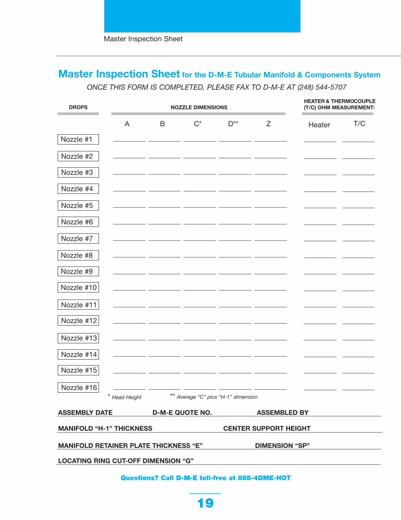
19
Nozzle #2
DROPS
ASSEMBLY DATE D-M-E QUOTE NO. ASSEMBLED BY
MANIFOLD “H-1” THICKNESS CENTER SUPPORT HEIGHT
MANIFOLD RETAINER PLATE THICKNESS “E” DIMENSION “SP”
LOCATING RING CUT-OFF DIMENSION “G”
Nozzle #1
** Average “C” plus “H-1” dimension
A B C* D** Z Heater
NOZZLE DIMENSIONSHEATER & THERMOCOUPLE (T/C) OHM MEASUREMENT:
ONCE THIS FORM IS COMPLETED, PLEASE FAX TO D-M-E AT (248) 544-5707
Nozzle #3
Nozzle #4
Nozzle #5
Nozzle #6
Nozzle #7
Nozzle #8
Nozzle #9
Nozzle #10
Nozzle #11
Nozzle #12
Nozzle #13
Nozzle #14
Nozzle #15
Nozzle #16* Head Height
Master Inspection Sheet for the D-M-E Tubular Manifold & Components System
Master Inspection Sheet
T/C
Questions? Call D-M-E toll-free at 888-4DME-HOT
20030 TubularMan_rev 9/13/06 11:42 AM Page 19

World HeadquartersD-M-E Company29111 Stephenson HighwayMadison Heights, MI 48071800-626-6653 toll-free tel248-398-6000 tel888-808-4363 toll-free [email protected] e-mailwww.dme.net web
D-M-E of Canada, Ltd.6210 Northwest DriveMississauga, OntarioCanada L4V 1J6800-387-6600 toll-free tel905-677-6370 tel800-461-9965 toll-free [email protected] e-mail
TMCAG-25-03/04a Milacron Company Litho in U.S.A.
20030 TubularMan_rev 9/13/06 11:42 AM Page 20