Embed Size (px)
Citation preview

Before The
FEDERAL COMMUNICATIONS COMMISSION
Washington, DC 20554
In the Matter of )
)
Petition for Rulemaking to Permit ) RM – ________________
Directional FM Antenna Modeling )
Through Use of Computational Methods )
To: Office of the Secretary
Joint Petition for Rulemaking
DIELECTRIC, LLC
EDUCATIONAL MEDIA FOUNDATION
JAMPRO ANTENNAS, INC.
RADIO FREQUENCY SYSTEMS
SHIVELY LABS
Petition for Rulemaking – Computational Modeling of FM Directional Antennas
ii
CONTENTS
I. There are Significant Costs in Time and Money Due to the Required Physical Measurement of
Directional FM Antennas that Can Be Saved through Use of Computational Modeling while
Simultaneously Maintaining or Improving Accuracy .................................................................................... 2
II. The Commission Has a History of Accepting Computer Modeling of Directional Antennas in Other
Broadcast Services, When Possible, Instead of Requiring Physical Measurements ..................................... 5
III. Issues with Physical Modeling and Example Showing that Computer Modeling Is At Least as
Accurate as Physical Measurements, If Not More So ................................................................................. 13
A. Range Measurement Inaccuracy .................................................................................................... 13
B. Mechanical Tolerances and Human Error with Physical Modeling ................................................ 14
C. Automated Optimization ................................................................................................................ 15
D. Significance of Polarization Ratio Determination ........................................................................... 16
E. Comparison of Physical and Computational Models ...................................................................... 17
IV. The Commission Should Revise its Rules to Make Computational Modeling Equivalent to, and
Acceptable in Lieu of, Physical Measurements for Characterizing Directional Properties of FM Radio
Transmitting Antennas ................................................................................................................................ 24
Appendix A
Proposed FCC Rules Modifications to Permit Computational Modeling of Directional FM Antennas
Appendix B
Antenna Installation Drawing
Appendix C
Antenna Proof of Performance Based on Scale Model Measurements
Appendix D
Horizontally Polarized Component Pattern Studies – Relative Field Data
Appendix E
Vertically Polarized Component Pattern Studies – Relative Field Data

Before The
FEDERAL COMMUNICATIONS COMMISSION
Washington, DC 20554
In the Matter of )
)
Petition for Rulemaking to Permit ) RM – ________________
Directional FM Antenna Modeling )
Through Use of Computational Methods )
To: Office of the Secretary
Joint Petition for Rulemaking
The parties listed on the front and signature pages hereto (the “Petitioners”) hereby respectfully request,
pursuant to Section 1.401 of the Federal Communications Commission’s Rules, that the Commission
modify its rules to accept computational modeling of FM directional transmitting antennas as an
alternative to the making of physical measurements of antenna characteristics and/or performance
whenever measurements now are required by the rules. In the cases of FM directional antennas currently,
measurements generally are required by the rules to provide data for filing with applications for licensing
to prove the performance of the antennas to be licensed. As will be shown, with currently available
computational modeling methods, such data can be obtained with adequate accuracy for the purpose, so
that the public interest will be served by the Commission enabling use of such methods in lieu of
measurements of actual antennas and their supporting and surrounding structures or scale models thereof.
To accomplish this objective, changes are proposed herein in the Commission's rules in Sections
73.316(c)(2), 73.1620(a)(3), and 73.1690(c)(2). In addition to language explicitly providing for
acceptance of data derived through use of computational modeling for license and other applications
involving FM directional antennas, language is proposed, comparable to requirements found elsewhere in
rules related to FM directional antenna applications, requiring documentation of the qualifications of

Petition for Rulemaking – Computational Modeling of FM Directional Antennas
2
those conducting computational modeling and describing the methods used to derive the data required to
be filed with each application involving an FM directional antenna for which the filing of such antenna
performance characterization currently is specified.
The Petitioners are manufacturers and users of FM directional transmitting antennas and are impacted by
the current requirement in the cited rules sections that only measured data characterizing the relative field
patterns of FM directional antennas be submitted as part of license applications involving such antennas.
Indeed, several of the Petitioners already use computational modeling in their design processes and then
must duplicate that effort at greater expense to construct physical models on which to make
measurements.
I. THERE ARE SIGNIFICANT COSTS IN TIME AND MONEY DUE TO THE REQUIRED PHYSICAL
MEASUREMENT OF DIRECTIONAL FM ANTENNAS THAT CAN BE SAVED THROUGH USE OF
COMPUTATIONAL MODELING WHILE SIMULTANEOUSLY MAINTAINING OR IMPROVING
ACCURACY
The rules for licensing of FM directional antennas in §73.316(c)(2) and §73.316(c)(2)(iii) currently state,
“(2) Applications for license upon completion of antenna construction must include the following:” ….
“(iii) A tabulation of the measured relative field pattern required in paragraph (c)(1) of this section.”
Read literally, since it asks for a tabulation of the measured relative field pattern upon completion of
antenna construction, this language would seem to imply that an FM antenna must be measured after
installation, through field measurements of the installed antenna, which can be quite impractical to make.
Such measurements would have been even more difficult to make when the rules first were promulgated
in 1963. Consequently, we make the assumption that the rule was interpreted initially to require that FM
directional antennas be measured on full-size test ranges since such ranges were available then for
characterizing both the azimuth and elevation patterns of broadcast television antennas.1 The antennas
1 For example, the RCA Broadcast Antenna Engineering Center had three such ranges on a 135-acre site in Gibbsboro, NJ, at least as late as 1984, when the facility was described in the RCA Broadcast News publication, Volume No. 174, March 1984, pp. 12 – 17, available here: https://worldradiohistory.com/ARCHIVE-RCA/RCA-Broadcast-News/RCA-174.pdf. Last checked 28 May 2021.

Petition for Rulemaking – Computational Modeling of FM Directional Antennas
3
would have been characterized prior to delivery for installation, and the provisions in the rule related to
certifications of installation according to manufacturer instructions by a qualified engineer and at the
correct orientation by a licensed surveyor would seem to support such an interpretation.2 Judging by a
review of a number of applications filed in the last couple decades, the use of full-size antenna
components and large ranges continues, but it has become the practice of some manufacturers making
such measurements to measure only portions of arrays having multiple layers or bays, with a sufficient
number of bays included in the measurement, in the judgement of the manufacturer, to properly create the
respective azimuth patterns in both the horizontally and vertically polarized components of the
transmitted signals.3 The elevation patterns in such cases generally are calculated rather than measured.4
Producing measurements of the type described requires maintenance of large tracts of land on which to
operate the full-size ranges, with the space amounting to tens of acres and distances involved in the
hundreds of meters so as to make proper measurements in the far fields of the antennas, where their
beams are fully formed. It also requires the ability to erect tower sections as part of the process, complete
with any attachments in the regions of the antenna apertures that will be found on the real towers on
which the antennas will be installed. This is necessary because the towers on which the antennas will be
mounted, along with any nearby appurtenances or accessories, are considered to be part of the structural
environments in which the transmitted signals can be reflected or reradiated, thereby affecting the patterns
of the antennas. The implications are that manufacturers must maintain inventories of wide assortments
of tower sections so that they do not have to fabricate too often a tower section matching what will be
used to support a particular antenna. Nevertheless, when any towers not already in their inventories of
sample sections are to be used to mount antennas, they either must obtain them from the tower
manufacturers or fabricate equivalent tower sections themselves. Then, all the appurtenances within
certain distances of the antennas must be obtained or fabricated and attached. If those appurtenances are
2 See §73.316(c)(2)(vii) and §73.316(c)(2)(viii). 3 See, for example, the license application in File Number: BMLED-20050207AAJ (KKJZ). 4 See, for example, the license applications in File Numbers: BMLED-20050809ACP (WMFO); BLH-20060323ABU (KZLA-FM, now KLLI-FM); BMLH-20101221ACA (KPWR); and BLED-20140313ADT (KTCN).

Petition for Rulemaking – Computational Modeling of FM Directional Antennas
4
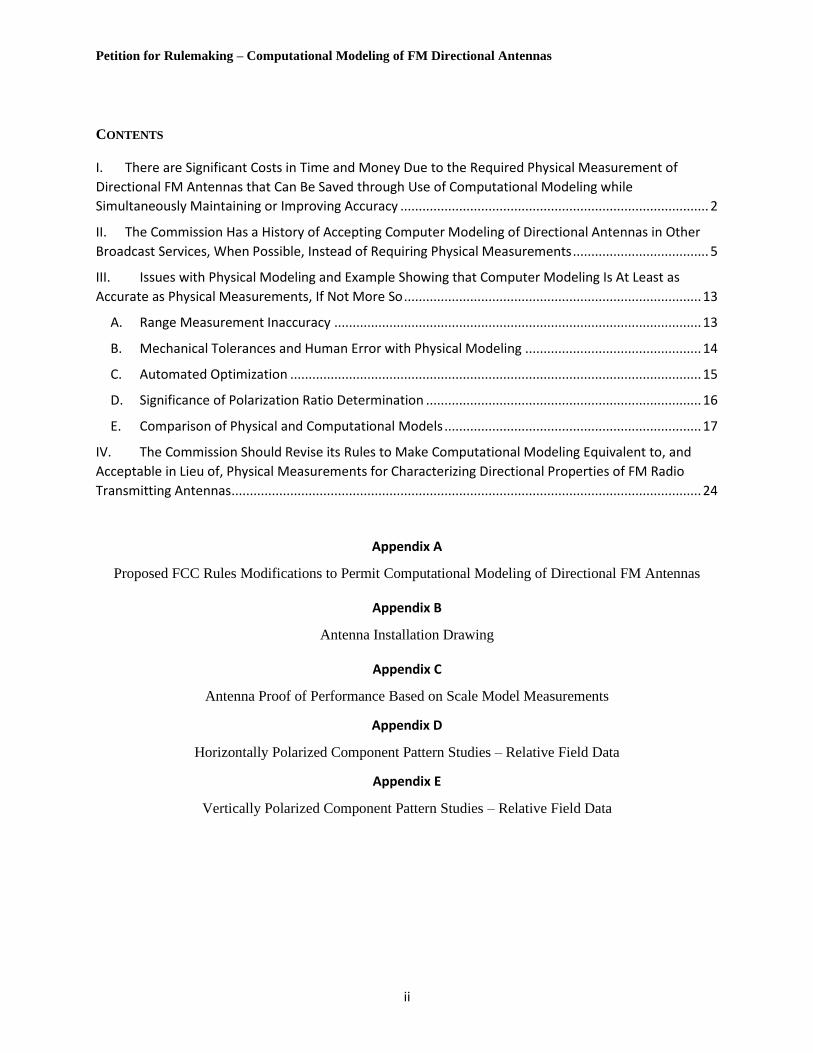
Figure 1 – Full-scale test range (left) and anechoic chamber with scale-model antenna (right) for antenna characterization
not commonly used, they could go to waste after a single use, adding to the cost to the purchaser of that
one antenna.
For some manufacturers, sometime in the intervening period between promulgation of the 1963 FM
directional antenna rule5 and now, it became routine practice to use scale models6 of antennas on
enclosed, indoor test ranges for characterizing the detailed performance of directional FM antennas. (See
Figure 1 for a comparison of full-scale and scale-model antenna characterization facilities.) It is the data
from measurements of the scale models on the indoor ranges that have been submitted with directional
FM antenna licensing applications based on those manufacturers’ antennas for at least several decades.7
To a certain extent, the burdens and costs of physical measurements of antennas have been somewhat
reduced historically by the Commission’s acceptance of measurements made on the scale models of
directional antennas,8 but requirements to construct physical scale models, including models of the related
towers and all their appurtenances still preclude the benefits of improved accuracy and cost savings that
can be derived from the use of computational modeling of directional antennas and the towers or other
structures on which they are mounted.
5 See discussion below on pp. 6 – 10. 6 The scale models typically are built for operation at frequencies roughly 4½ times higher (the two commonly used ratios are 4.4:1 and 4.5:1) than the intended frequencies of operation of the actual antennas. Thus, the scale models are built for operation at frequencies ranging from around 396 MHz to around 486 MHz to correspond with full-size antennas operating from 88 to 108 MHz. 7 See, for example, the license applications in File Numbers: BLED-20020905AAM (KCSN), scaling factor = 4.4; and BLED-20170802AEJ (WBUR-FM), scaling factor = 4.5. 8 Use of scale models is described in Part 73 of the FCC rules (2019 edition) only in §73.1690(c)(2)(iii) and only with respect to replacement FM directional antennas. §73.1690 became effective in March 1982 (47 FR 8590) but did not describe use of scale models at that time.

Petition for Rulemaking – Computational Modeling of FM Directional Antennas
5
II. THE COMMISSION HAS A HISTORY OF ACCEPTING COMPUTER MODELING OF DIRECTIONAL
ANTENNAS IN OTHER BROADCAST SERVICES, WHEN POSSIBLE, INSTEAD OF REQUIRING
PHYSICAL MEASUREMENTS
The procedures required or allowed by the FCC for characterization of antenna azimuth patterns vary
quite markedly between the several broadcast services – AM Radio, FM Radio, and Television. Azimuth
patterns, of course, help determine in which directions broadcast stations distribute their emitted signal
power, where they deliver service, and where they cause interference to one another. The techniques for
controlling where signals are emitted in the azimuth plane and how their emissions are measured have
improved over the century-long history of broadcasting via transmission of electromagnetic signals. They
also have progressed with the addition of the new services that came along, operating mostly at higher
frequencies in each case – from AM, to FM, to Television. Each of the services started out with intended
non-directional (or “omnidirectional”) antennas and azimuth patterns. In some early cases, azimuth
patterns accidentally turned out to be directional, and much was learned about how to create directional
patterns intentionally to permit reduction of interference between stations operating on the same or
adjacent channels. While the first AM stations went on the air starting in 1920, the first intentionally
directional antenna array took until 1931to start operation.9 It wasn’t until 1937 that the techniques for
designing AM directional arrays were fully documented.10 Methods eventually were developed to permit
designing directional AM antenna arrays using a special-purpose analog simulator based on a pattern
presented on a CRT,11 but adjusting and proving the correct operation of the directional arrays themselves
according to their designs required a large number of field strength measurements to be made following
any adjustment of the array until its pattern finally was proved. This was necessary because of interaction
9 WFLA, Clearwater, FL. See George H. Brown, “and part of which I was,” Angus Cupar Publishers, Princeton, NJ, copyright 1979 and 1982, p. 56. Also see, “The Development of the Directional AM Broadcast Antenna,” RadioWorld, June 14, 2019, updated July 15, 2020, http://www.radioworld.com/columns-and-views/roots-of-radio/the-development-of-the-directional-am-broadcast-antenna, last visited 28 May, 2021. 10 George H. Brown, “Directional Antennas,” Proceedings of the Institute of Radio Engineers, Vol. 25, Issue 1, January 1937, pp. 78 – 145. See also George H. Brown, “and part of which I was,” Angus Cupar Publishers, Princeton, NJ, copyright 1979 and 1982, pp. 55 – 69. 11 G.H. Brown, W.C. Morrison, “The RCA antennalyzer – an instrument useful in the design of directional antenna systems,” Proceedings of the Institute of Radio Engineers, Vol. 34, Issue 12, December, 1946, pp. 992 – 999.

Petition for Rulemaking – Computational Modeling of FM Directional Antennas
6
between the environment in which an antenna was constructed (in particular, the local ground
conductivity) and the behavior of the antenna azimuthal directivity and other characteristics. Given the
relatively low, medium-wave frequencies at which AM radio operates, the long wavelengths involved,
and the large structures they required for efficient emissions, such antenna systems, using a multiplicity of
towers as antenna elements, had to be constructed on the ground, where they were susceptible to such
interactions.
With the emergence of FM and then Television, broadcast signals moved to higher frequencies – VHF for
FM and both VHF and UHF for Television. The shorter wavelengths they implied permitted antennas to
be constructed as single, integrated structures instead of multiple, separate elements. Moreover, when
only local service is considered (disregarding ionospheric “skip” conditions), unlike AM frequencies,
which operate primarily with “ground wave” propagation, the VHF and UHF portions of the spectrum
function primarily on a “line-of-sight” (LOS) basis, meaning that transmitting antennas work best when
they are able to “see” the regions into which they will deliver their signals. Such LOS operation points to
placement of VHF and UHF antennas at high locations so that they can be “seen” farther from their
transmitting locations and they can deliver stronger signals throughout stations’ service areas. Higher
locations also help reduce multipath propagation, thus contributing to delivery of higher quality signals.
Fortunately, the ability to build transmitting antennas for FM and TV as unitary structures, mounted high
off the ground, means that their operation does not vary in such a way as to require periodic
measurements and correction of their operation, as is the case with AM directional arrays.
As with AM, early FM and TV transmitting antennas were basically omnidirectional. Over time,
directional antenna designs for VHF and UHF became available.12 The current FCC rules permitting use
of directional antennas for both FM and Television first were published in the Federal Register on the
same day, December 14, 1963, when a major reorganization and revision of the broadcast rules, contained
12 George H. Brown, “Directional Antennas for Television Broadcasting,” IRE Transactions on Broadcasting,” Vol. BC-6, Issue 2, August 1960.

Petition for Rulemaking – Computational Modeling of FM Directional Antennas
7
in “Subchapter C – Broadcast Radio Services,” was published. The reorganization moved the contents of
previous Parts 3 and 4 of the FCC rules and regulations to Parts 73 and 74, respectively. The rules related
to FM directional antennas were and are contained in §73.316 [FM] “Antenna systems,” and the rules
covering directional antennas for analog TV were and are contained in §73.685 [TV] “Transmitter
location and antenna system.” Rules for directional antennas transmitting Digital Television (DTV)
signals, which are relevant currently, mostly parallel the rules for analog TV and appear in §73.625,
“DTV coverage of principal community and antenna system,” which was promulgated in 1997, at the
time of adoption of the DTV rules. The following discussion applies to both §73.625 and §73.685 unless
specifically described otherwise.
It is notable that, while the rules for directional antennas for FM and TV were very similar at their initial
publication at their current section numbers, there were a few significant differences between them that
have led to different procedures over the years. To help clarify the following discussion, the year of
issuance of the referenced rule or its current applicability will be noted. In the 1963 FM case, it was
stated that, “[d]irectional antennas may not be used for the purpose of reducing minimum mileage
separation requirements but may be employed for the purpose of improving service or for the purpose of
using a particular site ….,” while the 1963 TV rules stated simply that, “[d]irectional antennas may be
employed for the purpose of improving service upon an appropriate showing of need.” Those restrictions
have disappeared over the years since, and an FM rule (§73.215 Contour protection for short-spaced
assignments) now exists specifically to describe how to address such situations. When the digital
transition took place in the Television service in the late 1990s and the 2000s, specific advantage was
taken of the potential for use of directional antennas to permit shorter spacing between stations, and such
use has become an everyday part of the television channel assignment landscape ever since.

Petition for Rulemaking – Computational Modeling of FM Directional Antennas
8
Turning back to the initial versions of the current rules on directional antennas, the 1963 FM rules
provided, in part:
§73.316(d) Applications for directional antennas. Applications proposing the use of directional
antenna systems must be accompanied by the following:
(1) Complete description of the proposed antenna system, including:
(i) a description of the means whereby the directivity is proposed to be obtained, and
(ii) the means (such as a rotatable reference antenna) whereby the operational antenna
pattern will be determined prior to licensed operation and maintained within proper
tolerances thereafter.
(2) Horizontal and vertical plane radiation patterns showing the free space field strength in
mv/m at 1 mile and effective radiated power in dbk for each direction. If directivity was
computed, the showing shall include the method by which the radiation patterns were
computed, including formulae used, sample calculations and tabulations of data. If the
directivity was measured, the method employed shall be fully described, including the
equipment used, and the resultant measured data shall be tabulated. …
(3) Name, address, and qualifications of the engineer making the calculations.
The 1963 TV rules provided, in part:
§73.685(f) Applications proposing the use of directional antenna systems must be accompanied
by the following:
(1) Complete description of the proposed antenna system.
(2) Orientation of array with respect to true north; time phasing of fields from elements
(degrees leading or lagging); space phasing of elements (in feet and degrees); and ratio of
fields from elements.
(3) Horizontal and vertical plane radiation patterns showing the free space field intensity in
millivolts per meter at 1 mile and the effective radiated power, in dbk, for each direction.
The method by which the radiation patterns were computed or measured shall be fully
described, including formulas used, equipment employed, sample calculations and
tabulations of data. …
(4) Name, address, and qualifications of the engineer making the calculations.
There were many commonalities between the two sets of rules: In construction permit applications
proposing directional antennas, they both sought complete descriptions of the proposed antenna systems,
free space field intensities in mv/m and effective radiated power values in dBk in each direction from the
respective antennas, and information on the methods used to calculate or measure the associated radiation
patterns, plus sample calculations and tabulated data. They also required contact information for and
qualifications of the engineer performing the calculations that were submitted. The most significant
difference between the two 1963 approaches to directional antenna rules was that the FM rules required a
“means (such as a rotatable reference antenna) whereby the operational antenna pattern will be
determined prior to licensed operation and maintained within proper tolerances thereafter,” while the TV
rules had no such requirement. So, while the FM rules required a method for producing a “proof of
Petition for Rulemaking – Computational Modeling of FM Directional Antennas
9
performance” on the antenna prior to its use and for its maintenance over time thereafter, the TV rules did
not. Indeed, the TV rules permitted either measurements or calculations of directional antenna patterns
(by virtue of lack of prescribing or proscribing either one) to be submitted with construction permit
applications, and no further demonstrations of performance of actual antennas were required thereafter.
Both the FM and TV rules related to directional antennas have been revised multiple times since 1963,
and the DTV rules have been added (in 1997). Currently, as in the past, most of the requirements for such
antennas being proposed and approved remain the same for both services. The last vestige of the
difference between the two sets of 1963 rules is that the current FM rules require that measured pattern
performance data for a directional antenna be submitted as part of the application for a license to cover
the corresponding construction permit once the antenna has been installed; the current TV rules (including
the DTV rules) only require pattern data for a construction permit and don’t define whether that data must
be derived through measurements or can be the product of calculations.
The real-world results of this rules difference are that directional TV antennas and their patterns are
specified almost exclusively using calculations, which, over time, have migrated to computational
modeling of the antennas, with no physical models of antennas, whether scale models or partial full-size
arrays, being constructed in advance of manufacturing of the antennas themselves, while directional FM
antennas still are built and documented in physical instantiations – some with full-size components on
full-size test ranges and some scaled to higher frequencies, smaller sizes, and possibly smaller test ranges
– with measured results from the pre-manufacturing test models submitted when it is time to license an
antenna. In the case of directional TV antennas, quality control of antenna patterns is obtained by making
near-field measurements directly on the radiating elements of the antennas to obtain relative field strength
and phase values that permit synthesizing the far-field patterns of antennas without moving the antennas
off their manufacturing stands. This approach provides considerable savings in both time and cost for
antenna manufacturers and ultimately for the purchasers of their antennas. Full-size, far-field range
testing remains available from at least some manufacturers to those willing to pay extra for it. In the

Petition for Rulemaking – Computational Modeling of FM Directional Antennas
10
cases of directional FM antennas, since it often is the data collected during the initial modeling exercise
that is submitted at the time of licensure, the accuracy obtained can be less than it might be with more
modern methods because of issues like the difficulties in obtaining high accuracy caused by ground
reflections on full scale test ranges, the inaccuracies that occur in scaling up from reduced-size models to
full-size antennas due to the dielectrics used on some components not scaling linearly, echoes inside small
anechoic test chambers that are not truly anechoic, difficulties modeling details accurately, and so on.
When comparing the three fundamental broadcast services and the treatment of their directional antennas
in the Commission’s rules, the AM antenna rules were updated over a decade ago (in 2008, after an effort
begun in 199113) to permit use of the Method of Moments computer modeling system, based on the
Numerical Electromagnetic Code (NEC) developed at the Lincoln Laboratories Federally-Funded
Research and Development Center (FFRDC) at MIT. The rules enabling use of the Method of Moments
apply to a large proportion of AM directional antennas in use in the U.S., but not all. Nevertheless, they
permit many directional AM arrays to be (re-)constructed directly from computer models without the
need for building test antennas to measure ground conductivity and without the need for repeatedly taking
many field measurements over a large geographic area in order both to tune and to prove the performance
of an antenna array. Also avoided are previously required periodic license parameter readings and
periodic monitor point readings. Thus, the payoff can be much simpler pattern maintenance and need for
much less frequent field testing. Over time, the Method of Moments has proved sufficiently accurate and
reliable that the FCC updated the relevant rule further in 2017 to eliminate requirements for “new
reference field strength measurements” upon filing of “subsequent license applications for the same
directional antenna pattern and physical facilities” and to permit use of Method of Moments techniques
on a wider range of AM antenna designs, among other relaxations.14
13 By the broadcast engineering consulting firms of Hatfield and Dawson; duTreil, Lundin, and Rackley; Lahm, Suffa & Cavell; Moffett, Larson & Johnson; and Silliman & Silliman. 14 FCC MB Docket No. 13-249, FCC 17-119, In the Matter of Revitalization of the AM Radio Service, Published November 3, 2017, 82 FR 51161.

Petition for Rulemaking – Computational Modeling of FM Directional Antennas
11
As has been discussed above, the TV/DTV rules already are flexible enough to permit use of computer
modeling both for design of antenna patterns and for testing of resulting antenna performance without the
need for physical models, either full size or scaled down, which add time and cost to the delivery of a
directional transmitting antenna. That leaves only directional antennas for FM broadcasting with the
requirements and burdens of having to go through the steps of first building models of antennas,
measuring those models and collecting the related data, manufacturing and installing the antennas, and
then submitting the data collected from the models, along with certifications by engineers and surveyors
that the installations were performed correctly, in order to license the facilities.
It is worthy to note that, in the recent television spectrum repack, as some TV stations moved from UHF
to Low-VHF, they needed new directional Low-VHF antennas. In several cases, the designs used were
those of FM directional antennas scaled to be larger, to work at the lower frequencies of TV Channels
2 – 6. Because they were to be licensed for use by TV stations, the new Low-VHF antennas could be
developed and proved with all the latest computer modeling techniques for design, manufacturing
adjustment, and quality control. Had those very same antenna designs and patterns been constructed for
the purpose of use a few MHz higher, in the FM band, only because of the differences in the FCC rules, it
would have been necessary to physically model them prior to building them and to physically measure
them to collect data for submission to the FCC during the licensing process. It also should be appreciated
that, had computer modeling not been permissible for design of directional television antennas, it would
have been essentially impossible for the industry to design, manufacture, test, and install the nearly 1000
antennas that had to be replaced to successfully complete the Post-Incentive Auction Spectrum Repack in
the minimal time allowed for the process.
The FCC has, over a long period and a wide range of technologies, accepted computer modeling of
systems or effects about which it sought input during its processing of applications of various kinds. One
example of the Commission’s acceptance of computer modeling is found in the FCC rules for RF
radiation exposure evaluation, as applied to portable devices. In August 1996, it added language to its

Petition for Rulemaking – Computational Modeling of FM Directional Antennas
12
rules on the subject in §2.1093(d)(3), which said, “Compliance with SAR limits can be demonstrated by
either laboratory measurement techniques or by computational modeling. [Emphasis added.]
Methodologies and references for SAR evaluation are described in numerous technical publications
including ‘IEEE Recommended Practice for the Measurement of Potentially Hazardous Electromagnetic
Fields – RF and Microwave,’ IEEE C95.3-1991.”15 [Last sentence subsequently replaced.]
A description of the use of computational modeling for demonstrating SAR limit compliance of a portable
device was published in 2015.16 In an article in the in-house magazine of Ansys, Inc., the publisher of
both Maxwell and HFSS modeling and analytical software packages, an engineer from Medtronic, one of
the largest manufacturers of medical devices, described the use of computational modeling to predict the
SAR levels produced by a wireless battery recharger to be used by those with subcutaneously implanted
neurostimulators. The charging process involved passing RF energy in the 3 kHz to 300 kHz frequency
range electromagnetically through skin and other tissues to a coil antenna under the skin. Both the
Maxwell and HFSS programs were used – Maxwell to make the SAR predictions and HFSS to validate
them. In addition, a physical instance of the power source was built, and its RF magnetic field energy
was measured, with the results used to provide further validation of the SAR values predicted by the
computational modeling. As shown in the paper, results of the finite element model (FEM) predictions
matched the physical measurements and the alternative software validation tool to a high degree, with
good accuracy. It should be noted that HFSS is one of the most widely used software modeling and
design tools for development of both directional and non-directional broadcast antennas as well as high-
power RF components of all types in the VHF and UHF spectrum regions.
15 61 FR 41017, Aug. 7, 1996 16 V. Gaddam, “Charged Up,” Ansys Advantage, Vol. IX, Issue 1, 2015, published by ANSYS, Inc., Canonsburg, PA, available at https://www.ansys.com/about-ansys/advantage-magazine/best-of-high-tech-2016/charged-up. Last checked 5 November 2020.

Petition for Rulemaking – Computational Modeling of FM Directional Antennas
13
III. ISSUES WITH PHYSICAL MODELING AND EXAMPLE SHOWING THAT COMPUTER MODELING IS
AT LEAST AS ACCURATE AS PHYSICAL MEASUREMENTS, IF NOT MORE SO
There currently are several software programs that can be used for modeling antennas as well as
environmental objects in proximity to the antennas, plus filters, transmission lines, hybrids, lumped
constant RF components, and so on. The modeling usually involves representation of the structures and
shapes of objects in three dimensions. Analysis typically involves capacitance, inductance, impedance,
phase, voltage standing wave ratio (VSWR), voltage breakdown, return loss, and other effects that exist
between elements of an electromagnetic design. Importantly, such elements can include all the same
structures that would be included, using current methods, in physically modeling an antenna in the
environment in which it will be installed, but with greater precision. Moreover, since the modeling takes
place in a computer, without the need for fabrication of structures and appurtenances and without the need
to maintain large inventories of tower sections and other structures that exist in the environments in which
such antennas are installed, it becomes practical to include more detailed and smaller elements that exist
on the antenna supporting structure and in the surrounding environment, leading to more accurate results.
Examples of the software programs available are several implementations and derivatives of the
Numerical Electromagnetic Code (NEC) and the Method of Moments (MoM), both mentioned
previously; High Frequency Structure Simulator (HFSS), based on 3D Finite Element Method (FEM)
techniques; CST Microwave Studio; and others. Most of the software packages are based upon “solvers”
that are useful for addressing specific design aspects. Consequently, modeling often may involve use of
multiple programs, depending on particular design and environmental issues to be studied.
A. Range Measurement Inaccuracy
Important aspects of range-based antenna pattern measurements, whether full-scale or scale-modeled, far-
field or conducted in anechoic chambers, are the alignment and reflectivity of the ranges used. Alignment
typically relies on mechanical bore-sighting, with an assumption that an antenna used to transmit signals
to an Antenna Under Test (AUT – regardless of whether it ultimately will be a transmitting or a receiving
antenna) is perfectly electrically aligned, which electrical alignment perfection depends, in turn, on

Petition for Rulemaking – Computational Modeling of FM Directional Antennas
14
mechanical alignment accuracy. Accuracy of the testing process consequently is constrained by both
mechanical and electrical deviations from the assumed perfect alignment, which deviations naturally will
occur.
The principal reasons for deviation of patterns from those expected from idealized ranges are reflections
from the range surface(s), unaccounted-for surrounding objects, positioner errors, and cables used to feed
the antennas. Sometimes signals from external sources also pose problems. The total field at a point in
space is the phasor sum of the test signal and any extraneous signals. The relative amplitudes and phases
of the desired and extraneous signals will vary with position along the test aperture, causing constructive
and destructive additions, thereby producing a measured pattern that will deviate from the pattern that
would have been produced had it been measured in free space.17
B. Mechanical Tolerances and Human Error with Physical Modeling
Software eliminates lengthy set-up and take-down of models as well as the need for a technician to be
physically present to adjust the model and take data points by hand. Accuracy is greatly improved using
simulation, as it removes mechanical tolerances and human error affecting the data. In the case of FM
pattern studies, information that traditionally has been recorded by hand, such as radiator locations and
parasitic element sizes and locations in space are replaced by simply exporting parameters from a
computer model. The full three-dimensional model can be sent directly to 3D Computer Aided Design
(CAD) software to produce detailed component manufacturing and installation documentation,
eliminating the likelihood of documentation error and physical measurement inaccuracies. Flow charts
that show typical steps in the transfer of information for both physical-model and computer-simulation
procedures are depicted in Figures 2 and 3, respectively.
17 Paraphrased from: Schadler, John L., "VHF and UHF Television Antenna Test Range Measurements," National Association of Broadcasters Engineering Handbook, 11th Edition, Copyright 2018, Garrison C. Cavell, Editor-In-Chief, Chapter 10.8, pp. 1883 – 1893.

Petition for Rulemaking – Computational Modeling of FM Directional Antennas
15
From the flow charts, it is evident that the transfer of information in the computer pattern study procedure
is significantly more efficient and less likely to inherit errors during the transfer of information. Drafting
and design personnel can work with the exact models that were used in pattern study simulations. These
models can be dimensioned directly and transformed into working installation diagrams for customers. In
addition to minimizing error possibility, this approach significantly reduces the time and resources needed
to perform pattern analyses. For instance, only virtual tower models are necessary to complete simulation-
based studies, as opposed to requirements for both drawn models and physical constructs for scaled or
full-size physical-model pattern studies.
C. Automated Optimization
Another advantage of designing in a virtual environment is that component geometry can be completely
optimized and not compromised by time, materials, and/or tolerances. Many variables can be adjusted
automatically and systematically, with complete data tables exported for next steps in design processes.
These results can be obtained through optimization algorithms that sequentially vary any number of
parameters, simultaneously analyzing any combination of pattern shapers, parasitic elements, and radiator
START
Tower Information Provided
by Customerto Sales Team
Tower Information Relayed
from Salesto Engineering
Engineering Team Creates
a CAD Modelof Tower
Tower StudyPerformed Using
Computational Model
CAD Modelis Exported to
Mechanical Design Software File
Drafting and Design Team CreateInstallation
Drawing
FINISHSTART
Tower Information Provided
by Customerto Sales Team
Tower Information Relayed
from Salesto Engineering
Engineering Team Creates
a Drawingof Tower
Tower Modelis Manufactured
Engineering Performsa Physical
Scaled Model Pattern Study
Vertical and Horizontal Parasitics
are Measuredby Technician
Parasitic Information Relayed to Drafting and Design Team
Antenna Installation Drawing Created
FINISH
Figure 2 – Information Flow Chart for Physical Model Pattern Study Figure 3 – Information Flow Chart for Computational Model Pattern Study

Petition for Rulemaking – Computational Modeling of FM Directional Antennas
16
dimensions along with positions in space to find best-fit solutions. Trial and error techniques traditionally
used to develop the geometry necessary to produce desired patterns are replaced by such artificial
intelligence optimizing processes. Solution criteria are set based on desired azimuth pattern results and
requirements of FCC rules, and multiple antenna design configurations can be studied in parallel to
reduce overall analysis time.
D. Significance of Polarization Ratio Determination
The FCC rules in §73.316(a) state that supplemental vertically polarized effective radiated power (ERP)
required to achieve circular or elliptical polarization cannot exceed the ERP authorized in the horizontal
plane. Since, in most cases, broadcasters consider the vertically polarized components to be more
important than the horizontally polarized components and therefore tend to maximize their vertical
signals, accurate polarization measurements are important. Accurately range-measuring the power ratio
of horizontally and vertically polarized components at any point in space is difficult, since no range is
completely free of reflections. The facts that horizontally and vertically polarized waves reflect from
surfaces differently and that there are inherent limitations in the pattern congruence of horizontally and
vertically polarized radiation in test antennas compromise accuracy. If a test antenna is linearly polarized
and is rotated from horizontal to vertical for polarization tests on an antenna, an assumption is made that
the beam is perfectly straight and has no wobble. If separate radiation paths are used to measure the two
polarizations, such as by switching between crossed dipoles, an assumption is made that the patterns and
gains of the two paths are identical. In reality, each of these approaches includes sources of error due to
failures of the attendant assumptions, which errors can be eliminated through use of 3D high frequency
simulation. Since simulations are computed in true free-space environments, any undesired effects of
surrounding environments, of anechoic chambers, or of asymmetric test antennas are eliminated, resulting
in more accurate azimuth patterns and H/V ratio values.

Petition for Rulemaking – Computational Modeling of FM Directional Antennas
17
E. Comparison of Physical and Computational Models
To show the validity of computer modeling in place of physical modeling of FM directional antennas, an
example design developed using both methods, i.e., physical modeling and computational modeling of the
same antenna for comparison with one another, has been provided by one of the signatories to this
petition.
In the example design, a directional pattern study for Station WHEM, 91.3 MHz, Eau Clair, WI, was
performed on a scale model FM test range on October 1, 2015, using a scaling factor of 4.4:1 for all
elements involved in the study. The scaled elements included a model of an antenna bay and identically
scaled models of parasitic elements and the mounting pipe to be used by the station. All the scaled-model
components were rotated through 360 degrees while receiving a signal at the appropriately-scaled
frequency from a linear cavity-backed source antenna. The horizontally and vertically polarized azimuth
patterns were measured in an anechoic chamber test range. The signal source and scale-model antennas
(the latter used as a receiving antenna) were mounted at identical elevations and at opposite ends of the
test chamber. A network analyzer was used to supply the RF signal to the source antenna at 4.4 times the
fundamental FM frequency (i.e., at 401.72 MHz) and to receive the signal intercepted by the antenna
under test. Photographs of the scale-model pattern study configuration are shown in Figures 4 - 7.

Petition for Rulemaking – Computational Modeling of FM Directional Antennas
18
Figure 5 – Side View of Scaled Physical Model Used for Pattern Study in Anechoic Range
Figure 4 – Isometric View of Scaled Physical Model Used for Pattern Study in Anechoic Range

Petition for Rulemaking – Computational Modeling of FM Directional Antennas
19
Figure 6 – Rear View of Scaled Physical Model Used for Pattern Study in Anechoic Range
Figure 7 – Overhead View of Scaled Physical Model Used for Pattern Study in Anechoic Range

Petition for Rulemaking to Permit Computational Modeling of Directional FM Antennas
20
The received signal strength was converted to a relative level, referenced to the source. The relative level
was stored on a computer that also acted as the master controller for the test system. The computer
controlled the measurement system via an IEEE-488 control bus. The final antenna installation drawing
provided to the customer is attached in Appendix B. The pattern packet validating antenna proof of
performance based on the scale model measurements is attached in Appendix C.
The physical, scale-model directional pattern study was replicated in an Ansys HFSS software
environment on January 27, 2020. The computational model pattern study was performed in a simulated
free-space environment using a full-scale CAD model of the antenna bay, the parasitic elements, and the
mounting pipe at the fundamental frequency of 91.3 MHz. Screen captures of this pattern study
configuration are provided in Figures 8 - 10.
Figure 8 – Front View of Full-Size Computational Model Used for Pattern Study

Petition for Rulemaking to Permit Computational Modeling of Directional FM Antennas
21
Figure 9 – Overhead View of Full-Size Computational Model Used for Pattern Study
Figure 10 – Isometric View of Full-Size Computational Model Used for Pattern Study

Petition for Rulemaking to Permit Computational Modeling of Directional FM Antennas
22
Results of the physical, scale-model, directional pattern study were accepted by the broadcaster and
demonstrate proof of performance and FCC pattern envelope compliance in the azimuth patterns of both
the horizontally and vertically polarized signal components. Results of the computational model
directional pattern study closely parallel those of the scale-model study. The horizontally polarized signal
component azimuth pattern of the computationally simulated antenna shows a maximum positive
deviation of 1.67 dB and a maximum negative deviation of 1.39 dB referenced to the horizontally
polarized signal component azimuth pattern of the scaled physical model antenna. Figure 11 displays the
overlaid horizontally polarized azimuth patterns and the FCC pattern mask. Azimuth pattern relative field
data tabulations for the two horizontally polarized pattern studies are attached in Appendix D.
The vertically polarized signal component azimuth pattern of the computationally simulated antenna
shows a maximum positive deviation of 1.00 dB and a maximum negative deviation of 0.59 dB
referenced to the vertically polarized signal component azimuth pattern of the scaled physical model
antenna. Figure 12 displays the overlaid vertically polarized patterns and the FCC pattern mask. The
figure shows that the computationally simulated antenna exceeds the FCC pattern mask in the vertical
polarization pattern by a minimal amount. Azimuth pattern relative field data tabulations for the two
vertically polarized pattern studies are attached in Appendix E.

Petition for Rulemaking to Permit Computational Modeling of Directional FM Antennas
23
Figure 12 – Comparison of Vertical Component Scale-Model Physical Pattern Measurement with Computational Model Results
Figure 11 – Comparison of Horizontal Component Scale-Model Physical Pattern Measurement with Computational Model Results

Petition for Rulemaking to Permit Computational Modeling of Directional FM Antennas
24
IV. THE COMMISSION SHOULD REVISE ITS RULES TO MAKE COMPUTATIONAL MODELING
EQUIVALENT TO, AND ACCEPTABLE IN LIEU OF, PHYSICAL MEASUREMENTS FOR
CHARACTERIZING DIRECTIONAL PROPERTIES OF FM RADIO TRANSMITTING ANTENNAS
Turning to the requirements currently in the Commission’s rules with respect to the information necessary
to be included in applications for FM directional antennas, requirements related to construction permit
applications are specified in §73.316(c)(1), and requirements related to license applications are specified
in §73.316(c)(2). For construction permits, only a tabulation of the proposed composite directional
antenna (azimuthal) pattern is required. For licenses, a long list of items to be included in applications is
specified in the rule. These items include a complete description of the antenna and its design, a plot of
the composite pattern of the antenna in relative field values, a tabulation of measured relative field values
at the bearings included in the pattern data submitted with the construction permit application, a statement
about the mounting of the antenna on the tower, a statement about the structure of the tower on which the
antenna is mounted, a statement that no other antenna shares the aperture with the antenna to be licensed,
a statement of the qualifications of the engineer overseeing the antenna installation and certifying that it
has been installed per its manufacturer’s instructions, a statement from a licensed surveyor that the
antenna is correctly oriented, and statements as to the RMS of the antenna and its coverage of its
community of license.
It is noteworthy that a statement of the qualifications of the engineer overseeing the antenna installation is
required, but no similar statement is required with respect to the qualifications of the engineer designing
the antenna, even though the design has far more to do with the performance of the antenna than does the
installation. It is the design engineer who will determine which elements of the tower, of its
appurtenances, and of the surrounding environment to represent in the model of the tower and antenna, be
it full size or scaled. It is the design engineer who will determine the antenna elements and components
to be used and the materials of which they are constructed, their dimensions, and other parameters. When
scale models are used, it is the design engineer who will determine how to scale such components as
dielectrics, the characteristics of which may not be linearly related to just their physical sizes. It is the

Petition for Rulemaking to Permit Computational Modeling of Directional FM Antennas
25
design engineer who will specify the installation procedures to be followed, as included in the
manufacturer’s instructions that the engineer overseeing the antenna installation will certify to having
followed. Yet only the installation supervisor must be qualified and his/her qualifications provided. But
it is the design engineer who can make a calculation or decision that could cause the intended antenna
performance to appear in documentation and/or measurements but not in practice.
Effectively, the FCC has entrusted manufacturers with establishing criteria for knowledge and experience
in their hiring of engineers who perform design tasks, while requiring those who follow a manufacturer’s
installation checklist to establish their qualifications directly with the Commission. Manufacturers
effectively certify to their customers that the design engineers they employ have the knowhow to design
the antennas that are needed for specific applications. Given the success of the antenna manufacturing
industry over the last 60+ years in delivering directional FM antennas that produce expected results in
terms of providing service where it is needed while avoiding interference to neighboring stations, it is
clear that the Commission’s choice to entrust manufacturers with qualifying design engineers was a good
one.
In the past, manufacturers of FM directional antennas needed to hire or train design engineers who had
experience building antennas at full or reduced scale and who knew which environmental elements that
would be in proximity to an antenna, once installed, should be included in modeling of the antenna during
the design process and during the taking of measurements required for filing with the Commission at the
time of licensing. The tools available, when the initial version of the current rules for FM directional
antennas first appeared in 1963, only included full-size or scaled modeling of antennas, combined with
physical measurements, to approximate the characteristics that would be obtained when an antenna was
installed. In the decades since then, computational methods have evolved to enable more accurate and
precise predictions of the antenna performance that would be obtained with particular material
characteristics, component shapes, dimensions, and other parameters used in the manufacturing of an

Petition for Rulemaking to Permit Computational Modeling of Directional FM Antennas
26
antenna, in combination with the various materials and shapes of objects that would be in proximity to the
antenna once it was installed.
To achieve the results of which the new computational methods are capable, it remains necessary for
those using the newer modeling tools to have both the experience and expertise necessary to decide which
elements in the environment near an antenna to include in modeling it and the accuracy required in
modeling those elements, as well as all the skills needed for designing antennas. Thus, aside from the
experience of physical construction of antenna models, the qualifications for antenna design engineers
remain the same regardless of whether physical or computational models are used in the design and in
predicting the performance of directional FM antennas. The computational models have the advantage,
however, of permitting communication of numerical descriptions of components from computational
modeling systems directly to computer numerical control (CNC) machinery that then can produce the
components far more accurately and repeatably than can be obtained using manual methods, thereby
obtaining the desired results more reliably.
The FCC has for decades entrusted manufacturers of FM directional antennas with engaging personnel
who can apply the necessary skills to designing such antennas. The basic knowledge, experience, and
expertise requirements with respect to antenna design and modeling remain the same when the newer
computational modeling techniques are applied as was the case prior to their availability. The obligation
on the part of the antenna manufacturers to deliver the antennas that they specify remains to the stations
that acquire their products, while only the installation of the antennas currently requires certification to
the FCC by engineers who provide their qualifications. It therefore stands to reason that the
manufacturers of FM directional antennas should be permitted to apply the new tools at their discretion
and that the FCC should accept the results of computational modeling as being just as valid as the results
from physical construction and measurement of either full-size or scaled models of such antennas.

Petition for Rulemaking to Permit Computational Modeling of Directional FM Antennas
27
Nevertheless, to establish confidence in the results of designs created using computational modeling and
to avoid having the permissive use of such tools abused by those without the necessary skills, it is
proposed that a provision be added to the rules to directly address the latter possibility. The new
provision is proposed to be inserted in new $73.316(c)(2)(iv) (with other provisions of §73.316(c)(2)
starting at the current (iv) be incremented by one to higher numbers, i.e., (v) through (x)). The proposed
new provision is largely based on terms in §73.1690(c)(2)(iii) and would apply to both new and
replacement designs of FM directional antennas. It would require that identification of the software tools
used, the processes applied, the elements included in the models, the qualifications of the designers, and
similar information be provided for each antenna for which computational modeling is applied in lieu of
the making of measurements. All other proposed changes but one comprise additions of the words "or
computationally modeled," or equivalent, adjacent to each relevant occurrence of "measured," to provide
for the permissive use of computational modeling whenever measurements are required currently. The
one exception is a new reference in §73.1690(c)(2)(iii) to the addition proposed for (new)
§73.316(c)(2)(iv). All the proposed changes in rules text are presented in Appendix A hereto.

Petition for Rulemaking to Permit Computational Modeling of Directional FM Antennas
28
Wherefore, for the foregoing reasons, the Petitioners respectfully request the Federal Communications
Commission to issue a Notice of Proposed Rulemaking proposing to adopt the language offered in
Appendix A to authorize the use of computational modeling of FM directional antennas to derive pattern
data in place of the making of physical measurements to acquire such data.
Respectfully submitted,
By: __/s/____________________
S. Merrill Weiss
Consultant to the Petitioners
Merrill Weiss Group LLC
227 Central Avenue
Metuchen, NJ 08840-1242
The Petitioners:
By: __/s/____________________
Keith L. Pelletier,
Vice President, General Manager
Dielectric, LLC
22 Tower Road
Raymond, ME 04071
By __/s/_____________________
Sam Wallington,
Vice President of Operations and Engineering
Educational Media Foundation
5700 West Oaks Boulevard
Rocklin, CA 95765
By: __/s/_____________________
Alex M. Perchevitch
President
Jampro Antennas, Inc.
6340 Sky Creek Drive
Sacramento, CA 95828
By: __/s/_____________________
Brandon J. George,
BDS Manager NA / Principal RF Engineer
Radio Frequency Systems
200 Pond View Drive
Meriden, CT 06450
By: __/s/_____________________
Angela Gillespie
Vice President
Shively Labs
188 Harrison Road
Bridgton, ME 04009
cc.: Albert Shuldiner, Chief, Audio Division, FCC Media Bureau
James Bradshaw, Senior Deputy Chief, Audio Division, FCC Media Bureau

Petition for Rulemaking to Permit Computational Modeling of Directional FM Antennas
29
Appendix A – Proposed FCC Rules Modifications to Permit Computational Modeling of
Directional FM Antennas
In the proposed text that follows, additions are shown underlined. There are no deletions. Changes in paragraph numbering are shown with arrows pointing from current numbers to new numbers.
§73.316 FM Antenna Systems (c) Applications for directional antennas. (2) Applications for license upon completion of antenna construction must include the following: (iii) A tabulation of the measured or computationally modeled relative field pattern required in paragraph (c)(1) of this section. The tabulation must use the same zero-degree reference as the plotted pattern and must contain values for at least every 10 degrees. Sufficient vertical patterns to indicate clearly the radiation characteristics of the antenna above and below the horizontal plane. Complete information and patterns must be provided for angles of –10 deg. from the horizontal plane and sufficient additional information must be included on that portion of the pattern lying between + 10 deg. and the zenith and –10 deg. and the nadir, to conclusively demonstrate the absence of undesirable lobes in these areas. The vertical plane pattern must be plotted on rectangular coordinate paper with reference to the horizontal plane. In the case of a composite antenna composed of two or more individual antennas, the composite antenna pattern should be used, and not the pattern for each of the individual antennas. (new iv) When a directional antenna is computationally modeled, as permitted in paragraphs (c)(2)(iii) and (c)(2)(x) of this section and in §73.1690(c)(2), a statement from the engineer(s) responsible for designing the antenna, performing the modeling, and preparing the manufacturer's instructions for installation of the antenna, identifying the software tool(s) used in the modeling, the procedures applied with the software, and listing such engineers' respective qualifications. Such computational modeling shall include modeling of the antenna mounted on a tower or tower section, and the tower or tower section model must include transmission lines, ladders, conduits, other antennas, and any other installations that may affect the computationally modeled directional pattern. Renumber iv → v Renumber v → vi Renumber vi → vii Renumber vii → viii Renumber viii → ix

Petition for Rulemaking to Permit Computational Modeling of Directional FM Antennas
30
(ix → x)(A) For a station authorized pursuant to § 73.215 or Sec. § 73.509, a showing that the root mean square (RMS) of the measured or computationally modeled composite antenna pattern (encompassing both the horizontally and vertically polarized radiation components (in relative field)) is at least 85 percent of the RMS of the authorized composite directional antenna pattern (in relative field). The RMS value, for a composite antenna pattern specified in relative field values, may be determined from the following formula: RMS = the square root of: [(relative field value 1)2 + (relative field value 2)2 + .... + (last relative field value)2] total number of relative field values (B) where the relative field values are taken from at least 36 evenly spaced radials for the entire 360 degrees of azimuth. The application for license must also demonstrate that coverage of the community of license by the 70 dBu contour is maintained for stations authorized pursuant to § 73.215 on Channels 221 through 300, as required by § 73.315(a), while noncommercial educational stations operating on Channels 201 through 220 must show that the 60 dBu contour covers at least a portion of the community of license.
§73.1620 Program Tests
(a) Upon completion of construction of an AM, FM, TV or Class A TV station in accordance with the terms of the construction permit, the technical provisions of the application, the rules and regulations and the applicable engineering standards, program tests may be conducted in accordance with the following: (3) FM licensees replacing a directional antenna pursuant to § 73.1690(c)(2) without changes which require a construction permit (see § 73.1690(b)) may immediately commence program test operations with the new antenna at one half (50%) of the authorized ERP upon installation. If the directional antenna replacement is an EXACT duplicate of the antenna being replaced (i.e., same manufacturer, antenna model number, and measured or computationally modeled composite pattern), program tests may commence with the new antenna at the full authorized power upon installation. The licensee must file a modification of license application on FCC Form 302–FM within 10 days of commencing operations with the newly installed antenna, and the license application must contain all of the exhibits required by § 73.1690(c)(2). After review of the modification-of-license application to cover the antenna change, the Commission will issue a letter notifying the applicant whether program test operation at the full authorized power has been approved for the replacement directional antenna.

Petition for Rulemaking to Permit Computational Modeling of Directional FM Antennas
31
§73.1690 Modification of Transmission Systems
(c) The following FM, TV and Class A TV station modifications may be made without prior authorization from the Commission. A modification of license application must be submitted to the Commission within 10 days of commencing program test operations pursuant to § 73.1620. With the exception of applications filed solely pursuant to paragraphs (c)(6), (c)(9), or (c)(10) of this section, the modification of license application must contain an exhibit demonstrating compliance with the Commission’s radio frequency radiation guidelines. In addition, except for applications solely filed pursuant to paragraphs (c)(6) or (c)(9) of this section, where the installation is located on or near an AM tower, as defined in § 1.30002, an exhibit demonstrating compliance with § 1.30003 or § 1.30002, as applicable, is also required. (2) Replacement of a directional FM antenna, where the measured or computationally modeled composite directional antenna pattern does not exceed the licensed composite directional pattern at any azimuth, where no change in effective radiated power will result, and where compliance with the principal coverage requirements of § 73.315(a) will be maintained by the measured or computationally modeled directional pattern. The antenna must be mounted not more than 2 meters above or 4 meters below the authorized values. The modification of license application on Form 302-FM to cover the antenna replacement must contain all of the data in the following sections (i) through (v). Program test operations at one half (50%) power may commence immediately upon installation pursuant to § 73.1620(a)(3). However, if the replacement directional antenna is an exact replacement (i.e., no change in manufacturer, antenna model number, AND measured or computationally modeled composite antenna pattern), program test operations may commence immediately upon installation at the full authorized power. (i) A measured or computationally modeled directional antenna pattern and tabulation on the antenna manufacturer’s letterhead showing both the horizontally and vertically polarized radiation components and demonstrating that neither of the components exceeds the authorized composite antenna pattern along any azimuth. (ii) Contour protection stations authorized pursuant to § 73.215 or § 73.509 must attach a showing that the RMS (root mean square) of the composite measured or computationally modeled directional antenna pattern is 85% or more of the RMS of the authorized composite antenna pattern. See § 73.316(c)(9). If this requirement cannot be met, the licensee may include new relative field values with the license application to reduce the authorized composite antenna pattern so as to bring the measured or computationally modeled composite antenna pattern into compliance with the 85 percent requirement. (iii) A description from the manufacturer as to the procedures used to measure or computationally
model the directional antenna pattern. The antenna measurements or computational modeling must be
performed with the antenna mounted on a tower, tower section, or scale model equivalent to that on
which the antenna will be permanently mounted, and the tower or tower section must include
transmission lines, ladders, conduits, other antennas, and any other installations which may affect the
measured or computationally modeled directional pattern. See §73.316(c)(2)(iv) for details of the
showings required in connection with applications filed related to FM directional antennas with data.

Petition for Rulemaking to Permit Computational Modeling of Directional FM Antennas
32
Appendix B – Antenna Installation Drawing
Appears on following page.

C
B
A
7 6 5 4 3 2 1
7 6 5 4 3 2 1
DATEAPPRCAD MAINTAINED. CHANGES SHALL BE INCORPORATED BY THE DESIGN ACTIVITY.
REVISION NOTEREV: ECO
COMPANY CONFIDENTIAL. INFORMATION CONTAINED HEREIN IS CONFIDENTIAL. IT IS THE PROPERTY OF DIELECTRIC. IT IS TO BE USED SOLELY FOR THE PURPOSE PROVIDED, AND IT IS NOT TO BE DISCLOSED TO OTHERS WITHOUT THE PRIOR WRITTEN CONSENT OF DIELECTRIC.
UNLESS OTHERWISE SPECIFIEDMANUFACTURING TOLERANCE AND PROCEDURES MUST BE IN ACCORDANCE WITH D78691. ALL ALUMINUM, COPPER, AND BRASS WELDING MUST COMPLY WITHA-62700, SECT. XIV "PRODUCTION WELDING PROCEDURES". STRUCTURAL STEEL WELDING MUST COMPLY WITH "AWS 1.1 CURRENT REVISION".
ZONESHEET
D
E
F
G
H
C
B
A
D
E
F
G
H
DDRAWING NO:
STATUS:
FINISH:
PART NO: / MATERIAL NO:
MATERIAL:
TITLE:
SHEET:
GAGE CODE
08441CHKD. BY
MANUFACT.ENG. 2 APPR.
OF
DATEDESIGNED BY
ENG. 1 APPR.
NAME
DETAIL BY
ANGLE PROJECTION
DIMENSIONAL TOLERANCES(UNLESS OTHERWISE NOTED)
DECIMAL DIMENSIONS3 PLACE DIMENSIONS ±.0052 PLACE DIMENSIONS ±.02FRACTIONAL DIMENSIONS
0"-6" ±1/32"ABOVE 6" UP TO 12" ±1/16"ABOVE 12" UP TO 48" ±1/8"
ABOVE 48" ±1/4"ANGULAR DIMENSIONS ±1/2°
REFERENCE DIMENSIONS ARE NOT FORMANUFACTURING OR INSPECTION
REFER TO D17800 FOR PAINTREFER TO D8110 FOR PLATING
SAP DOCUMENT NO:
A 10/23/15
RELEASED
300003299 ANT300003300 MNTS
N/A
Raymond, ME
INSTALLATIONWHEM DCRH1ERD 91.3 FM
S0 42428
017A570003:17:15 PM 1 1
rcmasonrcmasondfolsomrsmartNJCBjmayhan
1/29/20191/29/201910/15/1510/16/1510/22/1510/22/15
PRODUCTION RELEASE
ITEMS 203-1 AND 203-2 SHOWNITEM 203-3 HIDDEN FOR CLAIRITY
ITEM 203-3 SHOWNITEMS 203-1 AND 203-2HIDDEN FOR CLAIRITY
A
DETAIL A
6.697.92
89.2°
BAY 1
INSTALLATION NOTES:
1. ANTENNA SHALL BE INSTALLED PER THIS INSTALLATION DRAWING. ANY DEVIATIONS WILL VOID WARRANTY UNLESS APPROVED BY DIELECTRIC.
2. TO ACHIEVE ANY GIVEN PATTERN STUDY PERFORMED BY DIELECTRIC, THE PROVIDED ANTENNA MUST BE INSTALLED AND
ORIENTED AS DEPICTED IN THIS DRAWING. IF ANY SUCH PATTERN WAS NOT PROVIDED, THE ANTENNA ORIENTATION AND POSITION IS AT THE DISCRETION OF THE BUYER TO WHICH THE ANTENNA WAS SOLD. SHOULD ANY QUESTIONS ARISE DURING THE INSTALLATION PROCESS, CONTACT DIELECTRIC AT, 1-800-341-9678, TO ASSIST IN THIS PROCESS; BE PREPARED TO PROVIDE THE PART NUMBER OR DRAWING NUMBER SHOWN BELOW.
3. COMPONENTS ARE MATCH MARKED FOR EASE IN ASSEMBLY.
4. ITEM NUMBERS DEPICTED ON THIS DRAWING CORRESPOND TO ITEM NUMBERS LISTED ON ENCLOSED BILL OF MATERIAL.
5. APPLY THIN LAYER OF DC4 DOW CORNING COMPOUND TO ALL "O"-RING SEALS PRIOR TO ASSEMBLY.
6. UNLESS OTHERWISE SPECIFIED, THE TOP BAY MUST NOT BE LOCATED ANY CLOSER THAN 5 ft. BELOW THE TOWER TOP.
7. BAY TAP POINT DIRECTION INDICATED BY ARROWS LOCATED IN THE BAY IN ELEVATION VIEW.
8. THE VARIABLE TRANSFORMER IS SHIPPED WITH ALL PROBES FULLY INSERTED. AT INSTALLATION, BE CERTAIN TO LOOSEN
LOCKNUTS AND PULL ALL PROBES TO FULL OUTWARD POSITION. ALL PROBES MUST BE IN FULL OUTWARD POSITION BEFORE POWERING UP ANTENNA. REFER TO INSTRUCTION MANUAL FOR TUNING INSTRUCTIONS.
9. SUGGESTED LOCATION FOR TERMINATION MOUNT. LOCATION MAY VARY PER TOWER DESIGN.
10. FOR HEATED ANTENNAS ONLY: HEATER HARNESS TO BE DRESSED AND SECURED TO TOWER PER INSTALLERS
DISCRETION. LOOSE OR DANGLING WIRE IN RF FIELD WILL SHORT AND RESULT IN ANTENNA FAILURE.
11. REFER TO DRAWING A88212 FOR ALL HARDWARE TORQUE SPECIFICATIONS. * FOR FIBERGLASS APPLICATIONS, TORQUE MOUNTING HARDWARE TO 180 in-lbs (15 ft-lbs)
12. IT IS IMPORTANT TO MAINTAIN DOCUMENT FOR HISTORICAL PURPOSES. THE MOST CRITICAL PORTION OF INFORMATION TO BE MAINTAINED IS THE PART NUMBER AS SPECIFIED.
13. AFTER ANTENNA HAS BEEN INSTALLED AND TUNED ON THE TOWER, IT IS REQUESTED THAT A COPY OF THE TEST DATA
BE FORWARDED TO:
DIELECTRIC C/O FM ENGINEERING MANAGER 22 TOWER RD. RAYMOND, ME. O4O71 PHONE 1 – 800 – 341 - 9678
ANTENNA BOM P/N 300003299
ITEM NO MATERIAL MATERIAL DESCRIPTION REQ'D QTY UNIT
101 R86501 DCRH PLAIN BAY WITH RADOME 1 EA
103 R68429 JCT BLK END ASSY DCRH 1 EA
104 R75886 AFM 1-50 FM SHORT-STUB 53" LONG 1 EA
105 R80174 F/L INPUT SECT 1-50 x 70" 1 EA
106 R0046348501 ICE SHIELD KIT T/L 1-50 FM ANT 1 EA
107 R103326 EXTENSION TOP BLOCK 1-50 T/L 1 EA
108 R0023816125 HHCS SS 3/8-16X1.25 4 EA
109 R0163800000 LOCK WASHER SPLIT 3/8 SS 4 EA
MOUNT BOM P/N 300003300
ITEM NO MATERIAL MATERIAL DESCRIPTION REQ'D QTY UNIT
201 300003502 CUSTOM CHAIN MOUNT FOR 10. PIPE (Ø10.75) 1 EA
202 R15566 ANT MOUNT RETAINER 10.75 DIA 4 EA
203-1 300003503-1 PARASITIC KIT HORZONAL WHEM DCRH1ERD 91.3 MHz 1 EA
203-2 300003503-2 PARASITIC KIT HORZONAL WHEM DCRH1ERD 91.3 MHz 1 EA
203-3 300003503-3 PARASITIC KIT HORZONAL WHEM DCRH1ERD 91.3 MHz 1 EA
204 R0002187008 HOSE CLAMP 1.19-2.25 DIA 6 EA
90v TN
107
101
104 SEE NOTE 8
105
108109
201 BAY MOUNT
201 TERM MOUNT
201 TERM MOUNT
1'-0"
5'-9 1/2"
53
70
106 POSITION OVER PROBES
202
202
202
91.8°
37.40
37.40
31.02
30.1424.64
25.08
29.48
29.48
103
203-1
203-2
203-3
203-2
203-1
203-3
7.48
102.3°
101.2°

Petition for Rulemaking to Permit Computational Modeling of Directional FM Antennas
34
Appendix C – Antenna Proof of Performance Based on Scale Model Measurements

Petition for Rulemaking to Permit Computational Modeling of Directional FM Antennas
35

Petition for Rulemaking to Permit Computational Modeling of Directional FM Antennas
36

Petition for Rulemaking to Permit Computational Modeling of Directional FM Antennas
37

Petition for Rulemaking to Permit Computational Modeling of Directional FM Antennas
38

Petition for Rulemaking to Permit Computational Modeling of Directional FM Antennas
39

Petition for Rulemaking to Permit Computational Modeling of Directional FM Antennas
40

Petition for Rulemaking to Permit Computational Modeling of Directional FM Antennas
41

Petition for Rulemaking to Permit Computational Modeling of Directional FM Antennas
42

Petition for Rulemaking to Permit Computational Modeling of Directional FM Antennas
43

Petition for Rulemaking to Permit Computational Modeling of Directional FM Antennas
44

Petition for Rulemaking to Permit Computational Modeling of Directional FM Antennas
45

Petition for Rulemaking to Permit Computational Modeling of Directional FM Antennas
46
Appendix D – Horizontally Polarized Component Pattern Studies – Relative Field Data

Petition for Rulemaking to Permit Computational Modeling of Directional FM Antennas
47

Petition for Rulemaking to Permit Computational Modeling of Directional FM Antennas
48
Appendix E – Vertically Polarized Component Pattern Studies – Relative Field Data

Petition for Rulemaking to Permit Computational Modeling of Directional FM Antennas
49


![· l l l l l l l l l l l l l l l l l P˛F…WŁF=+ ÛFk°ÆF ÛF]&ÜF ıF¶F=a+¶FF EP˝F=+FÞU JæFk ÛFøFÒÙFk˝F=+;FµF 3-4 ÙFYk=+ =+F ıFkP⁄ FѶF GP¶FøFıF EFYÞ ıFk=+F](https://img.dokumen.tips/doc/110x75/5f8ec6e90e22f853025e45b4/l-l-l-l-l-l-l-l-l-l-l-l-l-l-l-l-l-pfwf-fkf-foef-ffaff.jpg)


![[EMC Publishing, LLC] Differentiated Instruction f(Bookos.org)](https://img.dokumen.tips/doc/110x75/55cf9cde550346d033ab5950/emc-publishing-llc-differentiated-instruction-fbookosorg.jpg)