Embed Size (px)
Citation preview

2011 Automobile Maintenance Advanced Course for the
Industrial Technical Instructors
Cotntnon Rail Direct Inj ection D· esel Engine
• In
Hyundai Tucson
Class No.: f\()" ~~-----
Instructor: Lin, Jin-jih

eEl:> HVUnORI
Practice: Fuel System Analysis
Topic : Oil Pressure Test for Low-pressuse pipe Time : 20 minutes
1. The fuel system of CRDi D-2.0
. Pressure Pu mp
II
Fuel Filter
Common rail
I 1
Low Pressure Pum p
2. Test of low-pressure area for CRDi D-2.0 engine fuel syst - Please connect the pressure gauge according to t
(~)Low-pressure gauge @)Low-preSSl.lre gauge so It pipe @connect.or (e)conn~ctor (connect to t he pipe) ~
pin~ . ·l:b
© ® IIIIICJll= CD ~
2
Injector
Fuel Case

r:B> HYUnORI
Practice: Fuel System Analysis
3. Measurement Method 1. Start the engine first and then close the engine after 5 minutes. 2. Connect the measurement gauge and then select checking, fuel pump starting,
then push the bottom of "start". 3. Read the figure on the pressure gauge and fill the blank.
Pressure of low pressure Unit Standard Value Judgement and Analysis (measurement)
"'-\. L kg/cm2 OK
4. Symptons Research
Pressure of low pressure Unit Reasons Analysis (measurement)
o ~ 1.5 kg/cm2 \ Qftj{-X it' .~A~.\ I "(S I I
0 1 tj'_ , ,
1.5 ~ 3 kg/cm2 \;\;oI[I/Y', A-~ 4~6 kg/cm2 C \ocv 6 1 . 'l--'.( !( K riA:, (}',
() I ( L> Oil Pressure Measurement of Low Pressure Pipe (D-2.0)
Using electrical pump
Pressure Measurement Judgement
1 1.5-3kg/cm' Normal
2 4-6kg/cm' Block in Fuel Filter or low pressure pipe
3 0-1.5kg/cm' Leakage of low pressure pipe or
breakdown of electrical pump
Attention: 1. There is some pressure difference between WGT and VGT in Euro-3o
WGT: Standard value is between 2.1'"""2.6 bar VGT : Standard value is between 2.3'"""2.8 bar
2. All cars in Euro-4 are VGT VGT : Standard value is 4bar v'
3. The overflow valve in Euro-3 is installed in fuel filter 4. The overflow valve in Euro-4 is installed in the face side of high pressu re pump, by using 16mm bolts set
3
HYUnORI Practice: Fuel System Analysis
- 'fopic . Measm enrent the quantity of fuel i etm n by using Cft'f' 1000 spedf ic tools -
Mobile check
Time : 20 minutes
1. The quantity of fuel return check for injector (engine can be starte d)
1. Separate the fuel return hose according to picture 1 2. Install plunger A according to picture 2 3. Connect injector fuel return hose connector B , clear hose, test
cup and mount according to picture 3 .
Picture 1 Picture 2 Picture 3
4. After starting the engine, do the following steps - one second in idle speed ~ 30 seconds in 3,000rpm ~ Stop t
he engine ~ Result observation (Picture 4)
- Do the above steps twice in order to
2. Results judgement
Results,.-..:.: _____________ -!.
4

~ HYUnORI
Practice: Fuel System Analysis
- IOPIC: Measurement of the quantIty of fuel return by uSIng CR I 1000 spe cific tools -
Static check Time : 20 minutes
High Pressu re Gauge
Fuel Pressure
Adjust Valve Connec tor • • ..... ..,., . mG
• • Pressure Sensor Connector
Parts for checking the quantity of fuel return
1. Engine can not be started 1. Separate the fuel return hose according to picture 1 2. Install plunger A according to picture 2 3. Connect injector fuel return hose connector B , clear hose, test
cup and mount according to picture 3
4. Separate each connector in injectors
Picture 1 Picture 2 Picture 3
5
CB;> HYUnCRI
Practice: Fuel System Analysis
-
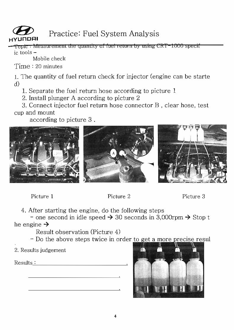
Picture 4 Picture 5 Picture 6
4. After separating the fuel pressure sensor connectors according to pic1 connect the battery and pressure sensor by using pressure gauge.
5. Separate the pressure adjust valve in the input of fuel pump accrodinf -Euro-3 (output control )7 one control way -Euro-4 (input and output contro1)72 control ways
6. After separate the connector of fuel pressure adjust valve according connect fuel pressure adjust valve to the battery, - to prevent from the damage of fuel pressure adjust valve.
Hope to connect to the battery only in the measurement. (within 5 rr.
6

(8) HVUnORI
Practice: Fuel System Analysis
-
Picture 7 Picture 8 Picture 9
7. Connect the connector of separated fuel adjust valve by using fake resi~ according to picture 7
- only for Euro-4 (if it is for Euro-3, the way for fuel pressure adju~ input and output, then the fake resistance needs to be set.
- If fake resistance is not set yet, the electrical fuel pump could not v test of high pressure pump.
8. Turn on the power switch of high pressure gauge 9. Start the engine - 5 seconds
- not more than 5 seconds, the rpm has to over 200 rpm when the en The battery must be good for a good test result.
10. Read the highest figure in high pressure gauge according to picture 8. 11. After observing the fuel quantity of fuel return clear hose according to
fill the blank and analysis the result.
7

r:B;> HYUnoRI
Practice: Fuel System Analysis
-2. Judgement for the quantity of fuel return in high pressure pump and injectors
Pressure of High Pressure pump
Quantity of fuel return for injectors
Quantity of
CASE Pressure of high pressure fuel return for Judgement injectors
1 1000-1800
0-200mm Normal (above1000)
2 0-1000 200-400mm Breakdown of
(under 1000) (above 200mm) injector
Breakdown of
0-1000 0-200mm high pressure
3 pump (under 1000) (under 200) (not enough
pressue)
8
Judgement
Checking Item
Change the injector that over 200mm
Checking the line of high pressure pipe

c:BY HYUnORI
Practice: Fuel System Analysis
- Topic: Pressure measurement of high pressure pump by using CRT-I000 specific tools Time : ~~~'~~---------------------------------------------.
Connector for Fuel pre ssure adjust valve
(!)
\%112:1:1 ~t'l' i?'jOlE~ r ,~ ID :fI &'J ;;:: ~, m?t,it~~ :1:~~ ~ ~Ol ~
......-L. .....
Connector for
Pressure sensor
Parts for checking high pressure pump
1. Engine can not be started 1. After separating the high pressure pipe according to picture 1, please put
the cover to prevent from the impurities go inside the injector (mark A). Install fuel adjust valv
e in common rail (mark B) and 3 common rail plunger (mark C).
2. Install plunger A according to picture 2 After '-''''' ... JL ...... '
001 002
9

-Practice: Fuel System Analysis
(DSeparate all injector pipe -Torque in installing: 250-290kg.m
@put the cover to prevent from the impuriti es go
inside the injector (mark A).
@Install fuel adjust valve in common rail (mark B) and 3 plunger adjust valve (rna
rk C).
Judgemen
Picture 4 Picture 5
4. Separate the pressure adjust valve in the input of fuel pump accroding -Euro-3 (output control )~ one control way -Euro-4 (input and output control)~2 control ways
5. After separate the connector of fuel pressure adjust valve according 1 connect fuel pressure adjust valve to the battery, -- to prevent from the damage of fuel pressure adjust valve.
Hope to connect to the battery only in the measurement. (within 5 r
10

c:B;> HVUnORI
Practice: Fuel System Analysis
-
Picture 6 Picture 7
6. Connect the connector of separated fuel adjust valve by using fake re: according to picture 6 - only for Euro-4 (if it is for Euro-3, the way for fuel pressure adju~
input and output, then the fake resistance needs to be set. - If fake resistance is not set yet, the electrical fuel pump could not v
test of high pressure pump. 7. Turn on the power switch of high pressure gauge 8. Start the engine - 5 seconds
- not more than 5 seconds, the rpm has to over 200 rpm when the en The battery must be good for a good test result.
9. Read the highest figure in high pressure gauge according to picture 7 and analysis the result.
11

cB:>. HYUnORI
Practice: Fuel System Analysis
-2. Judgement for the quantity of fuel returnj for high pressure pump and injector
Pressure of High pressure pump
3. Trouble Analysis
Pressure of NO High pressure p
ump
1 1000-1500bar
2 0-1000bar
4 Obar
Attention:
Judgement Remarks
Judgement Remarks
-The situation of fuel filter needs to check before changing high pressure Pl and to judge if the impurities exists inside
-If the impurities exists inside the fuel filter, necessary parts need to be ch( including fuel tank, after clean them.
12
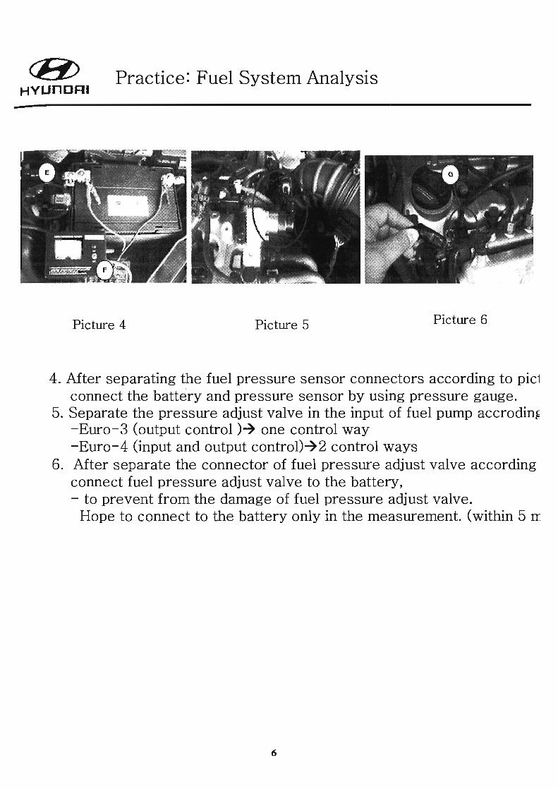
Course: HYUNDAI D-2.0 CRDi Common Rail Direct Injection Diesel Engine
Instructor: Lin, Jin-jih
(8) HYUnORI Service Training . CRDi - Common Rail Direct Injection Diesel Engine
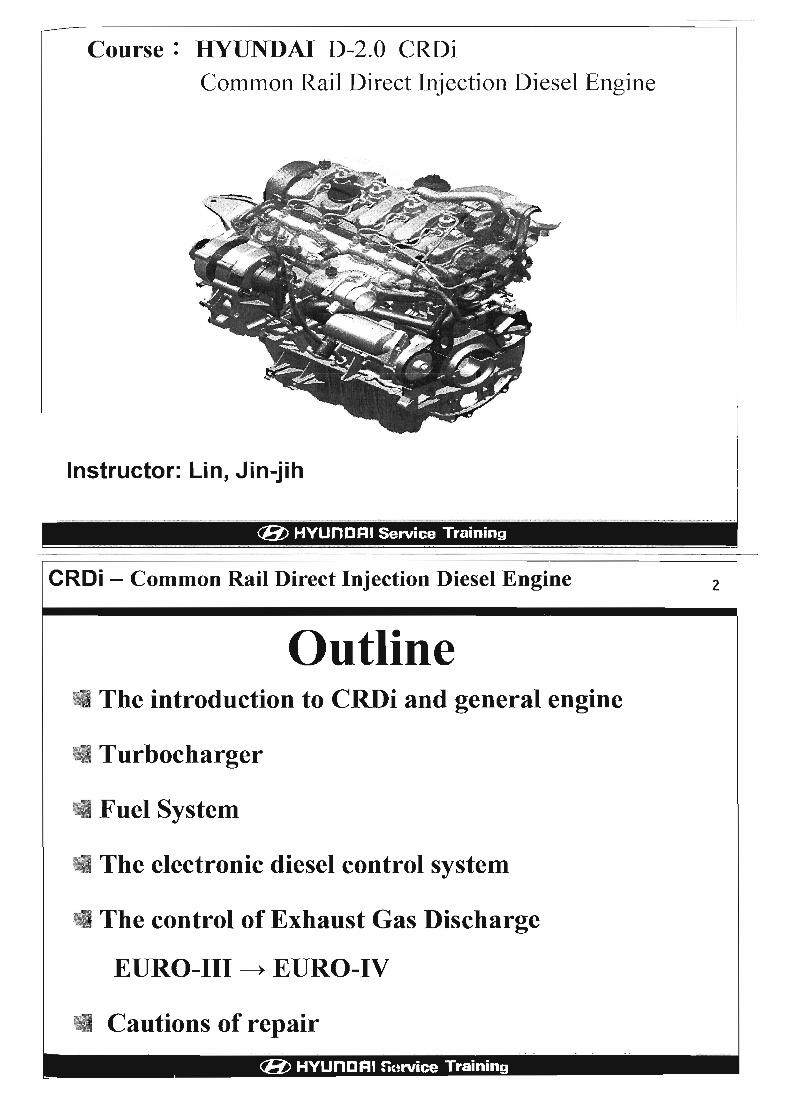
Outline • The introduction to CRDi and general engine
.. Turbocharger
;I Fuel System
.. The electronic diesel control system
d The control of Exhaust Gas Discharge
EURO-III ~ EURO-IV
• Cautions of repair
(8) HYUnORI nurvica Training
2

CROi - outline
Types Models Engine Displacement
CC(L)
CPI JM Tucson
D-2.0 2000 cc FO Trajet
CP3 HI Starex A-2.5 2500 cc
Delphi HP Terracan J3-2.9 2900 cc
CRDi : Common Rail Direct Injection
CPt : Common Rail Pump 1
CP3: Common Rail Pump 3
(Ii/) HYUnDRJ Service Training
3
EMS ( Engine Management System)
Bosch
Bosch
Delphi
---------------------------CROi - outline 4
CP1 0-2.0 CRDi Engine on two models
.. FOTrajet, ......• ·° 1 JM . Tucson . 0. .. 1
(Ii/) HYUnORI !iHrvice Training •

CRDi - outline
CP3 A-2.S CRDi Engine on :
. Ht Starex
CRDi - outline
Delphi J3-2.9 CRDi Engine on :
. HP Terracan
The Difference betweenCPl,CP3ahd .· Delphi ··
CPt CP3 Delphi
The control of fuel Outlet Inlet Inlet
quantity
Fuel Temperature 0 0 Sensor
Pressure Limit 0 Valve
Fuel Temperature Easy to go Not Easy to Not Easy to
up go up go up
Low Pressure Electric Gear Type Vanes Type
Pump Type
5
6
(8) HYUnCRJ !l .. ,rvice Training " .

0-2.0 CRDi - High Speed Direct Injection 7
• Power UP and the Economy of Fuel Consumption
- SOHC 4 valves and swing rocker arms
- Turbocharger with inter cooler
- Bosch common rail electronic diesel control (EDC)
- Electronic controlled and high precision Injectors are Installed in the center of the combustion chamber.
- Injection pressure reaches to 1,350 bar
• Low Emission and Low NVH
- There is pilot Injection before main Injection
- Balance Shaft
- EGR System and Catalytic Converter
(E:/) HYUnDRI Service Training .
The Development of Diesel Engine 8
• The Development of Diesel Engine
90 92 94 96 98 200Q 02 04 06 Year
(E:/) HYUnDRI n,1rvice Training

0 -2.0 - High Speed Direct Injection 9
Items • HTI D-2.0f Engine
D-Engine
EMS Bosch
Model
Displacement (cc)
The Driven Way of High Pressure Pump
The Control of Injectors
Fuel Injection
The Max. Fuel Pressure
The Control of Fuel Pressure
Heating Device
Valve Lash
(8) HYUnDRI Service Training
FC,LC,SM
1.se & 2.0e
Camshaft Gear
Inductive Current ( 20A ) Controlled by EMS
Pre-Injection
Main Injection
1350 bar
Outlet Control
Glow Plug
Fuel Heater
Coolant Heater
HLA
•
Timing Belt 10
Valve Driven System
- SOHC 4 valves and swing rocker anns
- Blacksmithing camshaft and hardening intake cams.
- Low friction roller and minimized slipping component.
. Hydraulic Lash Adjuster maintain no or low noise .
. Camshaft drives CR pump
• - Timing Driving System
• - Belts drive camshaft and auto tensioner
(8) HYUnDRI f'lfJrvice Training

Driving Belt 11
cross-section driving belt
(8) HYUnORI Service Training
Main Engine Parts
- Oil pump is installed in the oil pan.
- Driven by crankshaft small gear
- Oil used: CE 10W30
12
Main Characteristics
- Peak of ignition pressure: 150 bar
- Forging crankshaft and 5 flat rolling main bearing
- Full balanced crankshaft and 8 reverse balanced weight
- 2 balanced shaft are in the oil pan. (Lancaster Type)
- Completely reliable moving components (piston/bearing)
Balanced shaft module
(8) HYUnORI 5arvice Training • ---- ------ --------- --- -- - - ---

Turbocharger
WGT ( Waste-gate Turbocharger)
VGT
13
(
) ".
"
( Variable Geometry Turbocharger) (Ii/) HYUnDRI Service Training .
Turbocharger 14
WGT (Waste-gate Turbocharger)
VGT (Variable Geometry Turboch _1T1lo_
. (Ii/) HYUnDRI n!)rvice Training

CRDi- WGT (Waste-gate Turbocharger) 15
• System Chart
• Inter Cooling
Inter cooling is the process that the air passes the inter cooler to reduce the temperature of compressed air intake, and increases the density of oxygen in the intake air. It is combined with the turbocharger, and obtain high level and equal combustion, so the engine power is increased 15%.
(1i/) HYUnORI Service Training
CRDi - WGT (Waste-gate Turbocharger)
• Waste-gate Passage valve (Waste-gate I Regulation Valve) will reduce the exceed manifold pressure (over boost) during high speed, and make turbocharger system reach the peak of intake pressure to obtain highest boost reaction. After accurate metering, waste-gate intakes the exhaust emission to the turbocharger, and limits the speed of the turbocharger shaft to control the boost pressure.
wastegate Boost Pressure
Boost Without wastegate
Desired boost
Engine -+------------------~~Speed
(1i/) HYUnORI ~!)rvice Training
Turbocharger
Turbine In1et
16
CRDi - VGT ( Variable Geometry Turbocharger) 17
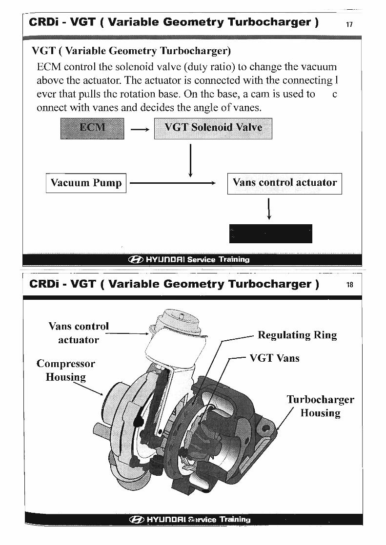
VGT ( Variable Geometry Turbocharger)
ECM control the solenoid valve (duty ratio) to change the vacuum above the actuator. The actuator is connected with the connecting I ever that pulls the rotation base. On the base, a cam is used to c onnect with vanes and decides the angle of vanes.
1 1 Vacuum Pump 1---------.· I Vans COlltrolactuator I
1
(8) HYUnDRI Service Training
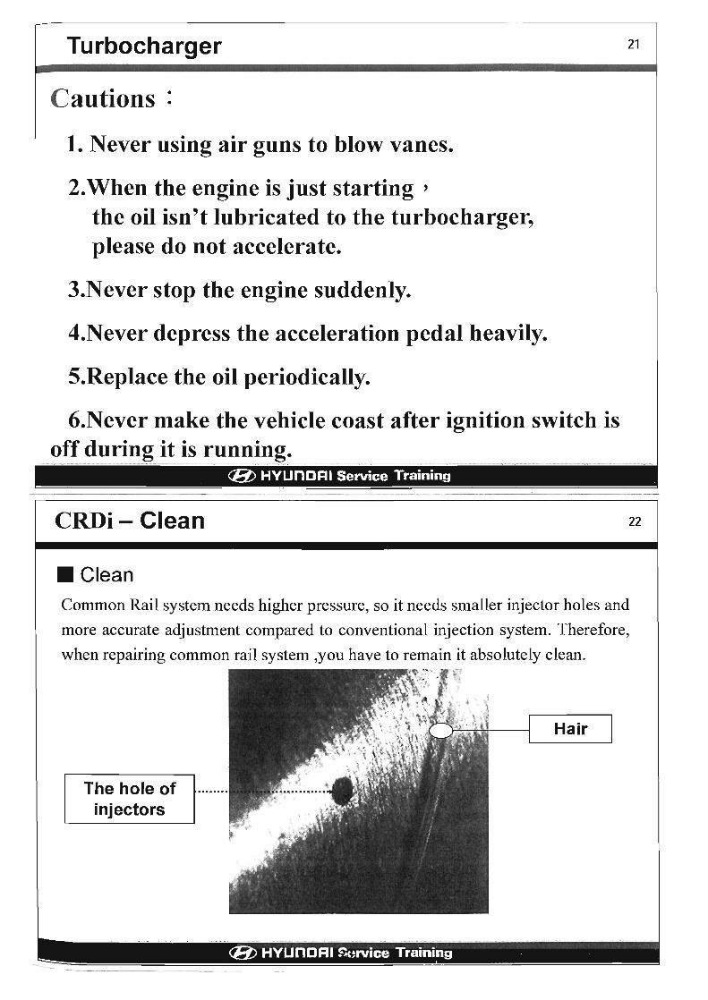
CRDi - VGT ( Variable Geometry Turbocharger) 18
Vans control ---- Regulating Ring actuator
Compressor Housing ~
Turbocharger Housing
(8) ~YUnDRI ~~rvice Training ,

CRDi - VGT ( Variable Geometry Turbocharger) 19
~High Speed and high load: ~Low Speed and low load:
The exhaust gas has large contact area, and the turbocharger's reaction and speed goes up (Max horse power is increased to 10-15%)
Because of narrow flow quantity area, the motion is reached to highest. (Max torque is increased to 5 -15%)
High Speed : Vanes Open Low Speed : Vanes Closed
(8) HYUnDRI Service Training
Main Advantages of CRDi - VGT
.Improve the horse power (10 -15% ) : High efficiency during low speed, and reduces the horse power loss of exhaust during high speed
• Improve the acceleration ability(10-15%) :
Improve the instant reaction
• Improve the fuel consumption(5-100/0) : Effective engine output
.Fast warm-up : Higher boost temperature, boost pressure, and exhaust back pressure .
• Match the emission regulations easily: Reduce the emission of smoke, control the air intake, lower the emission during idle speed.
--=::: - - --~-----
20
Turbocharger
Cautions:
1. Never using air guns to blow vanes.
2.When the engine is just starting' the oil isn't lubricated to the turbocharger, please do not accelerate.
3.Never stop the engine suddenly.
4.Never depress the acceleration pedal heavily.
5.Replace the oil periodically.
6.Never make the vehicle coast after ignition switch is off during it is running.
(E/) HYUnORI Service Training
21
.
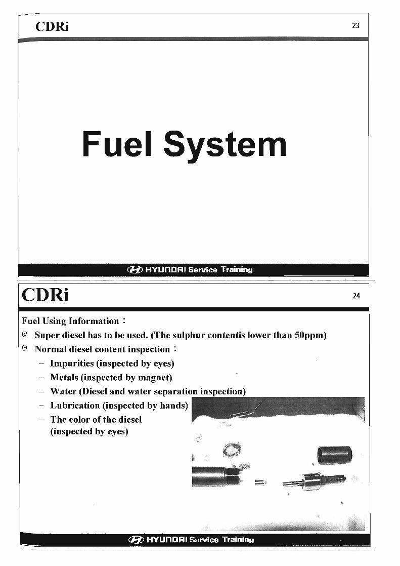
CRDi- Clean 22
• Clean Common Rail system needs higher pressure, so it needs smaller injector holes and
more accurate adjustment compared to conventional injection system. Therefore,
when repairing common rail system ,you have to remain it absolutely clean.
The hole of injectors
~~;, ',.., ~ ,
Hair
(E/) HYUnORI ~i,(~rvice Training •
enRi 23
Fuel System
(Ii/) HYUnORI Service Training .
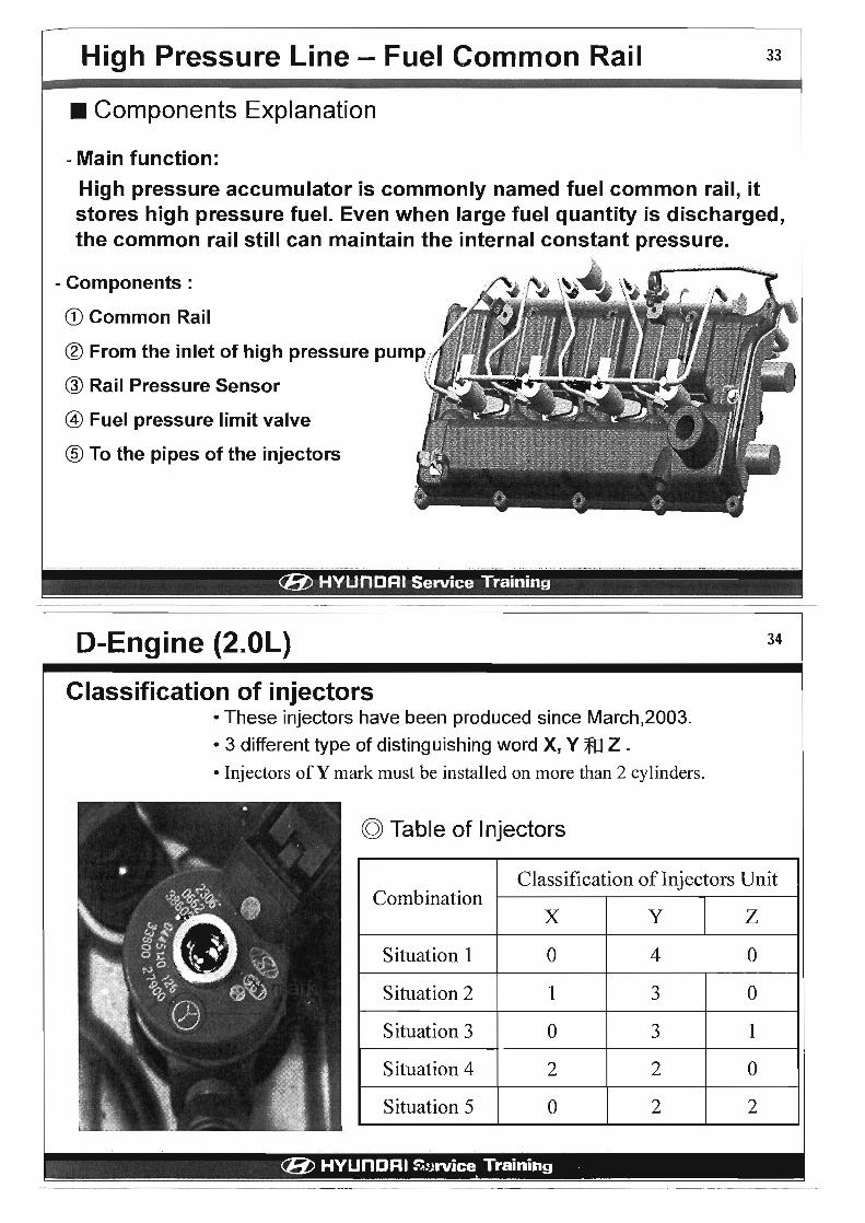
CDRi Fuel Using Information:
@ Super diesel has to be used. (The sulphur contentis lower than 50ppm)
@ Normal diesel content inspection:
Impurities (inspected by eyes)
- Metals (inspected by magnet)
- Water (Diesel and water separation inspection)
- Lubrication (inspected by hands)
- The color of the diesel (inspected by eyes)
- $--.
- , -
24
(Ii/) HYUnORI Snrvice Training •

0-2.0 Introduction 25
CRDI-D ENG FUEL SYSTEM ,1 Common rail
Injector
Pressure regUlator valve
low Dressure DumD
(8) HYUnDRI Service Training
High pressure pump
Fuel filter
Low Pressure Line - Fuel Filter 26
• Components Explanation
-Because of several reasons, common rail system needs more pur
ified fuel compared to conventional diesel system.
-Especially in cold climate, water and solid contaminants will ca
use worn, corruption, clog in filter, corruption on the surface of
metal, pressure loss, and less lubrication in high pressure pump.
- In order to reduce these latent problems, there are Bosch fuel f
i1ter and fuel pre-heater with water separation 0
- Main Components:
CD Main Filter
® Fuel Temperature Switch
® Water Separate Sensor
@ Fuel Pre-heater
® Air drain pump (only for A-2.S J -2.9 model)
(8) HYUnDRI ~~'rvice Training

Low Pressure Line - Fuel Heating System
• System Explanation - Purpose: To prevent diesel wax occurred ( To stabilize the diesel in cold climate)
- Working Temperature:
On : lower than -5°C
Off : higher than 3°C
• Wiring Diagram
Battery
Fuel Temperature S witch
Fuse Box
(8) HYUnORI Service Training
Fuel Temperature Switch
27
.
High Pressure Line - Pressure Control Valve
• Components Explanation
- Main function: According to the engine speed and load, injection pressure will be controlled.
CD High engine speed and load: The perturbation motion in combustion chamber is high, so it needs higher pressure fuel to help combustion.
28
® Low engine speed and load: If the injection pressure is too high during low load, the penetration pressure of injectors will be over, some fuel will directly injected to the cylinder wall. This will produce smoke and unburned hydrocarbon.
- The process of pressure control:
CD The rail pressure is measured by rail pressure sensor.
® The signal is sent to EDC ( Electronic Diesel Control)
® According to the engine speed and load, proper fuel quantity is calculated.
@ PWM (Pulse Width Modulation) controls the pressure control valve, and reaches t he pressure needed.
(8J HYUnORI ~i)rvice Training . • - - ----- ---- ----- -_.'", '-'-

High Pressure Line - Pressure Control Valve
• Components Explanation - Type:
29
CD Outlet Control: It is located at the end of the accumulator line, increases or reduces the total quantity of fuel return, and controls the output pressure of high pressure pump.
® Inlet Control: It is combined with high pressure pump and controls the fuel quantity from supply pump to high pressure pump.
* Outlet Control Type :
Advantages : The rail pressure can moved up instantly.
Drawbacks : When the car is decelerated suddenly, the unnecessary rail pressure will be difficult to release, and it wastes motion of energy.
* Inlet Control Type:
Advantages: When the car is decelerated suddenly, the rail pressure can be controlled accurately to avoid consuming motion of energy.
Drawbacks: The rail pressure cannot moved up instantly.
(E/) HYUnDRI Service Training .
High Pressure Line - Pressure Control Valve
• Components Explanation
- 2006 Tucson uses Outlet" Inlet Control Type p ressure control valve
- As showed below : Trajet uses Outlet Control Type pressure control valve
High Pressure Pump
Supply Pump
30
Control Valve
(E/) HYUnDRI f'~Jrvice Training •

High Pressure Line -The 0 eration of Pressure Control Valve Outlet Control
31
t
(8) HYUnORI Service Training -----------------------------High Pressure Line - High Pressure Pump
• Components Explanation
- Main Components:
CD Driving Shaft
® Offset Cam
® Pumping Parts and Pump Piston
@ Inlet Valve
® Outlet Valve
Inlet Valve I r-I ------,
. Outlet Valve
32
(8) HYUnORI S:~rvice Training . •
High Pressure Line - Fuel Common Rail 33
• Components Explanation
- Main function:
High pressure accumulator is commonly named fuel common rail, it stores high pressure fuel. Even when large fuel quantity is discharged, the common rail still can maintain the internal constant pressure.
- Components :
CD Common Rail
® From the inlet of high pressure pump ..
@ Rail Pressure Sensor
@ Fuel pressure limit valve
® To the pipes of the injectors
(8) HYUnORI Service Training .
D-Engine (2.0L) 34
Classification of injectors • These injectors have been produced since March,2003.
• 3 different type of distinguishing word X, Y;fa Z .
• Injectors ofY mark must be installed on more than 2 cylinders.
© Table of Injectors
Combination Classification of Injectors Unit
X y Z
Situation 1 0 4 0
Situation 2 1 3 0
Situation 3 0 3 1
Situation 4 2 2 0
Situation 5 0 2 2
(8) HYUnORI ~~)rvice Training •

High Pressure Line - Injectors
• Components Explanation - Main function: <" ,I ..
( :
Vertically installed injectors inject the proper quantity of fuel into combustion chamber at the proper time.
How to attend this function:
CD Complete electronic control
® In every short circle of injection, multi-injection will be produced.
,
S I "d " I G I ;j
L--_o_en_o_l_v_,a_v_e_--I'~ .................................................................. ............ , .... I
Hydraulic Servo System
Hole Type Nozzle
* Initial operation current: 80V/20A
"
., I - "
(8) HYUnDRI Service Training
35
.
High Pressure Line - Injectors
• Components Explanation Closed
- Components : CD t' CD Fuel Return
® Connector
® Solenoid Valve
@ Fuel Inlet
® Valve Ball
@ Drain Port
(j) Supply Port
@ Valve Control Chamber
® Valve Control Plunger
®
@)
@) Supply Passage ®
® Injector Needle
36
Open
(8) HYUnDRI Sl)rvice Training . . •
i J

High Pressure Line - Injectors
• Components Explanation: - Operation :
CD Injectors closed ( no operation) :
Solenoid valve does not operate and drain port is closed. Valve spring pushes the valve ball to drain port seat. The pressure in valve control chamber is the same as nozzle chamber.
® Injectors open ( Injection starting) :
37
Solenoid valve is operated by inductive current and the operation force is higher than the valve s pring force of drain port opening. When drain port opens ' fuel will flow to fuel tank from valve c ontrol chamber via fuel return pipes. This makes the pressure is not balanced between valve contr 01 chamber and nozzle chamber. The reduced pressure in valve control chamber makes the inject or needle open and start to inject the fuel.
@ Injectors closed ( Injection finish) :
As long as the solenoid valve doesn't operate, valve spring will push down the armature, make valve ball close the drain port 0 Drain port is closed to build pressure in control room. This pressure let the pressure between valve control chamber and nozzle chamber obtain balance, and nozzle is closed.
(8) HVUnORI Service Training --------------------------------------------------------------------------------
High Pressure Line - Injectors • Components Explanation:
- Pilot Injection: 25'" 15<> 5° 0" -5" -100
~ . ./ ~ rYJ ~a-p . il\
L /" ." 1)/
. ~
~~. 1-,... 2-'-:'
~~ ,.,
~.
~r ~ .. ~.&." ~ ~. ~ ,\ ~ . ~ .A -"
r.,..
" " ~ .. , • ~ . .1
1 = Pilot Injection
2 = Main Injection
la = Combustion Pressure with Pilot Injection
2a = Combustion Pressure without Pilot Injection
38
(8) HVUnORI Snrvice Training .

High Pressure Line - Injectors
• Components Explanation : - The Purpose of Pre-Injection:
Reduce Combustion Noise
CD Combustion Noise
® HC Emission
@ Fuel Consumption (Injection beginning delayed)
- Working Condition:
Idle speed and a little engine load
- Principle:
Diesel engine will not combust immediately after fuel into cylinders. Therefore, it will cause serious combustion noise when the diesel is ignited.
In order to reduce combustion noise and combust during idle speed, it must increase evaporation and chemistry form to reduce the ignition time. This effect could be obtained by a little quantity of injection before main injection. It is called pre-injection 0
(E/) HYUnDRI Service Training
39
---------------------------------EDC 40
Electronic Diesel Control
(EDC)
(E/) HYUnDRI S.~rvice Training •

EDC - Input I Output
Input> 1. Mass Air·Flow Sensor· "',' " .. ;.,. . ...
2~' ECT S~hsor
3. IAT Sensor
ECM
I Output> 1. Injectors
2. Fuel Rail Control Valve
3. Relay
- Main
- Glow Plug
- Cooling Fan
- Air Conditioning Fan
4. VAC Regulator of EGR
5. Pre-heater ( Coolant)
6. CAN
(8) HYUnORI Service Training
41
-------------------------------EDC- ECM
• Components Explanation :
- Clear Trouble Code:
42
When trouble codes occurred and were stored in ECM, only Hi-scan pro can be used to clear codes in ECM.
- Required Signal of ECM Output:
Maintain the pressure constant in high pressure accumulator (Common Rail) => P > 150 bar ( Instant pressure should be less than 150 bar)
To start and stop the actual injection sequence => CKP and CMP Signal are normal.
ECM Connector
PLUG "K' PLUG "M"
40 CJ S 24:rrILLLLLLLLLILLLlXJ 6
d3 :; :::::::; : : : : : : : : : : :~ 1002 81: I II I I I I r I, ¥ I I I I I I I HE
(8) HYUnORI Z(~rvice Training

........ _ - -----.. _ -
EDC - General Items 43
- Emergency Mode:
When ECM is malfunctioned on important Input/Output Signal, it will switche d to Emergency Mode 0 It will cause:
CD Reduce horse power
® Reduce max. rpm
® Without EGR (according to equipments)
- Emergency Stop
If the following system components got problem ' ECM will emergently stop t he engine:
CD Injectors
® CKPSensor
® Pressure Control Valve
@ Fuel Leak
- Caution: When the engine is running or after the engine is stopped less than 30 seconds, do not repair the engine.
(8) HYUnORI Service Training .
EDe - Heat Film Type Mass Air Flow Sensor ( AFS ) 44
• Components Explanation: - The principle of hot film sensor is to heat the sensor and transfer the air mass. Compared to gasoline engine, mass air flow sensor of diesel engine is mainly the limit of E GR. Intake air temperature is built in.
- Functions :
CD EGR Feedback Control
® The correction of fuel quantity when suddenly acceleration or deceleration.
Mass Air Flow Sensor
ECM AFS Output (V)
89 t--i:------+--++---, B+(12V)
reference (V) 971 ···- tl--------··-·--l--. +-.I ·-- ~/
IAT Output (V) 86 1-1!----·---·--·-+---I-· I-----I%~~t_-_4to Ground
88t--ir-----+--++----~
(8) HYUnORI SHrvice Training •

EDC - Intake Air Temperature Sensor ( IAT ) 45
• Components Explanation [Characteristic Curve]
IAT Sensor is built in AFS ° LI - .. ....
Using NTC to detect the variation of temperature, so the! \, '.', ensor's main function is to measure the intake te ., mperature. j
'~.-......
, .. _-.......,------- -When malfunction occur, the temperature of IAT is set to J.
50°C. "1XT4'~/'& .;.. '~"C
Trouble Codes Symptom Details EGR MIL
Inspection
DTC CC Fuel Fuel Condition =0 Closed Limit on
C001 Signal is lower than limit (Signal <224mV)
Ignition 0110
C002 Signal is higher than the limit y Switch is
(Signal>4.97V) ON
(Malfunction : 50°C) v ," " '''~'W~YY''Y' ' ''YY''''''Y''Y'''' ''''Y''Y "'Y'-""Y " W" " ~SY='~"Y" Y'_Nvv _ ' ~Y"=vw,,~vY,,_yyy=~'.'· Y~" "" '" ,_,"'v='yyyyy " """" y··V V Vy··y·"Nyy·· · ·y y··y=·,yyyyyyyy,-yy· ··,~y"" " .. · ··· · · yY~YVN ·· =-'·,y,.w" "N·,·""¥yVy y·"N · ·y·· y .. v".yyv·, ·" '···.y_··_ ·, .·"··, · ·"v·._~·,, v · ."N v · __ r.wyv· ·''' y ,·.y· .. =V· ."",··WW'_'···'··V_'_"W·,,V·
(/i/) HYUnDRI Service Training .
EDC - Accelerator Position Sensor ( APS )
• Components Explanation : - Accelerator Position Sensor is used to detect driver's acceleration or
deceleration, and sends signal to ECM. ECM decides injection quantity and proper timing by this signal. There are two sensors in APS
46
(Accelerator Position Sensor) , APS 1 and APS 2. APS 1 is the main sensor to t ell ECM about driver's motion. APS 2 is the sub sensor to monitor APS 1 m alfunctioned or not. The output value of APS 2 is half of APS 1.
APS1 reference ECM
rp r~ -...t ... ,., ~ .. .. -...... ~ .'" ...... ,~ 00
11111 APS1 Signal
,""",':«'*':"':::-:'~~:">OOO««~. _ ... ~. {- '-.J
11M APS1 Ground -...I
~ APS2 reference
I m r (XI L.. ...
APS2 Signal
.11 I-~ : -{- 00 0
APS2 Ground
(- ~
(8; HYUnDRI ~~'rvice Training •

EDC - Crank Position Sensor (CKP) :
• Components Explanation : - Crank Position Sensor (CKP):
47
Crank Position Sensor is named CKP technically. The operation is to detect and
calculate the teeth (60-2) on the pulse gear, sends the position of every piston in
combustion chamber to ECM, and decide the actual injection timing. This important
information is calculated in ECM by using CKP sensor.
ECM
101
99
100
Ground
Signal (+)
Signal (-)
(F:/) HYUnORI Service Training -----------------------------------EDC - Camshaft Position Sensor (CMP) 48
• Components Explanation : - Camshaft Position Sensor (CMP) Camshaft position sensor detects the initial position of camshaft by Hall effect.
Magnetic teeth are mounted to the camshaft and rotates with it. When teeth pass the
CMP Sensor, the magnetic field will transform the electron inside of the
semiconductor into current direction that passes through the chips. This causes short
voltage signal (Hall voltage), and let ECM know the location of 1stpiston's
compression stroke_
ECM
104
103
Ground
CAMSHAFT POSITION SENSOR
Sensor Signal N ~ I-t--------'--.......:....;+___; -<> ~
VM1
(F:/) HYUnORI ~t1rvice Training

EDC - Rail Pressure Sensor (RPS)
• Components Explanation
- Rail Pressure Sensor (RPS) :
49
The main function of rail pressure sensor is to measure the instant pressure in the rail,
and sends the output voltage to ECM correspond to the operation voltage. To shorten
the inaccuracy in rail pressure sensor during pressure measurement, RPS must maintain
proper accuracy to operate fast.
ECM RAIL PRESSURE SENSOR
Signal 91 ~~~~~------~-r---.
reference 90~~~~~------~-+~
Ground 92 ~-;~~~-------&--r------J
"
(8) HYUnORI Service Training .
EDC - Engine Coolant Temperature Sensor (ECT) 50
• Components Explanation: - Engine Coolant Temperature Sensor (ECT) : Engine coolant temperature sensor is located in the passage of engine coolant on the top of cylinder
head. It detects the engine coolant temperature, and send signal to ECM.
It senses the variation of the temperature sensor.
The higher temperature is, the resistance of temperature sensor is lower.
ECM controls the injection timing by this signal, and limit the idle speed of the engine by ECT
output. At the same time, when the ECT value is higher than the value in ECM, ECM will reduce the
fuel quantity.
ECM Temperature gauge
Ground 85 1---------11---
Signal
(BJ HYUnORI ~1f~rvice Training •
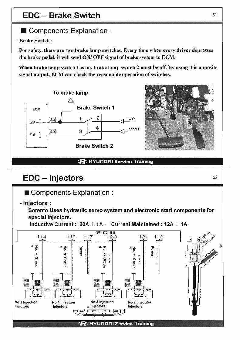
EDC - Brake Switch 51
• Components Explanation: - Brake Switch :
For safety, there are two brake lamp switches. Every time when every driver depresses the brake pedal, it will send ON! OFF signal of brake system to ECM.
When brake lamp switch 1 is on, brake lamp switch 2 must be off. By using this opposite signal output, ECM can check the reasonable operation of switches.
To brake lamp
Brake Switch 1
1 2 VB
54_~~(O_.3~) ____ -+3 __ 4 VM1
Brake Switch 2
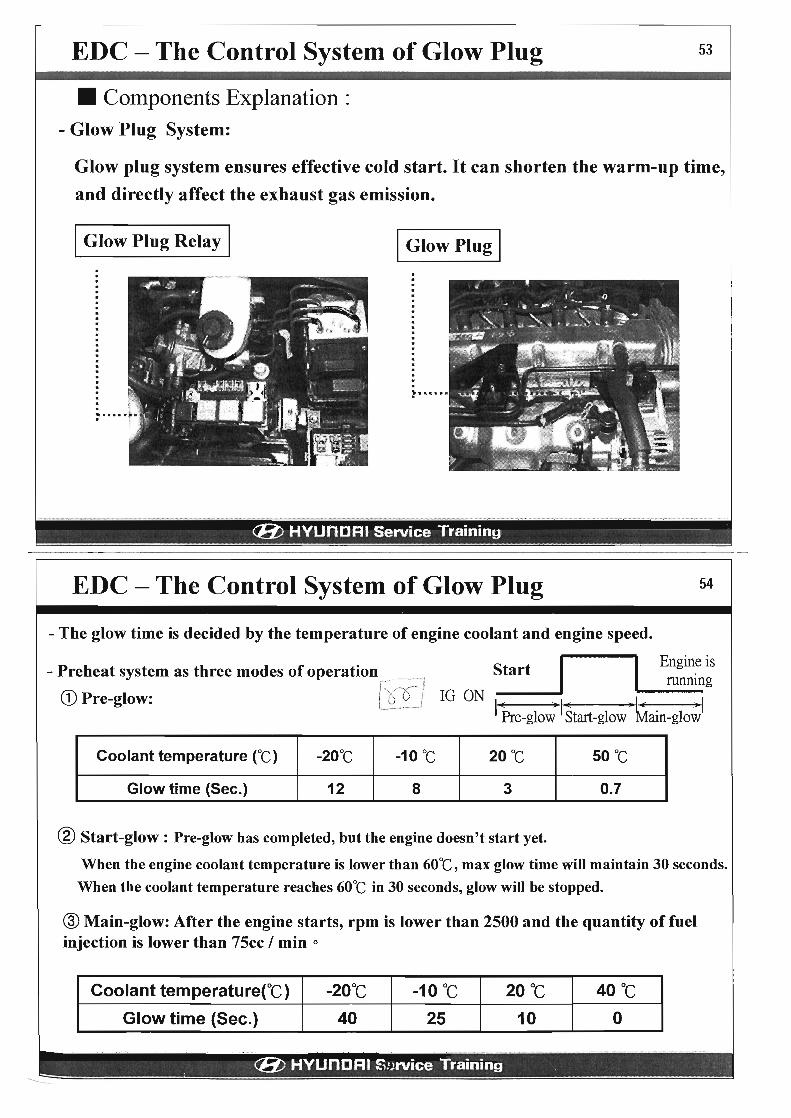
(E/) HYUnDRI Service Training ------------------------------------------------------------------------EDC - Injectors
• Components Explanation
- Injectors :
52
Sorento Uses hydraulic servo system and electronic start components for special injectors. Inductive Current: 20A ± 1A, Current Maintained: 12A + 1A
114
o.z P 1 G) .. 0 s::: ::::I
No.1 Injection Injectors
,-+,
E G U 119 117 120 121 118 ~ .-+-. .-+-.. ..-h ~
o.z "tJ o.z o.z "tJ P 0 P p 0
~ ~ 4 CD 3 2 CD .. r .. G) G) G) • .. .. .. ! 0 0 s::: s::: 0
s::: ::::I ::::I ::::I
No.4 Injection No.3 Injection No.2 Injection Injectors = Injectors Injectors
~/ t:f2 .!~ (E/) HYUnDRI S:,rvice Training
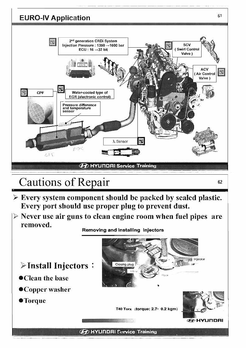
EDC - The Control System of Glow Plug
• Components Explanation : - Glow Plug System:
53
Glow plug system ensures effective cold start. It can shorten the warm-up time,
and directly affect the exhaust gas emission.
I Glow Plug Relay I I Glow Plug I
l' •••••
(/ij) HYUnDRI Service Training .
EDC - The Control System of Glow Plug 54
- The glow time is decided by the temperature of engine coolant and engine speed.
I I Engine is - Preheat system as three modes of operation __ . :' -:~i Start running
CD /'::O ! IG ON ---. ' 1 Pre-glow: ___ ~ ___ l I Pre-glo; I Start-glow'" ~ain-glo~,I
Coolant temperature rC) -20°C -10°C 20°C 50 °c
Glow time (Sec.) 12 8 3 0.7
® Start-glow: Pre-glow has completed, but the engine doesn't start yet.
When the engine coolant temperature is lower than 60°C, max glow time will maintain 30 seconds.
When the coolant temperature reaches 60°C in 30 seconds, glow will be stopped.
® Main-glow: After the engine starts, rpm is lower than 2500 and the quantity of fuel injection is lower than 75cc / min °
Coolant temperatureCC) -20°C -10°C 20°C 40 °c
Glow time (Sec.) 40 25 10 0
(/ij) HYUnDRI Z~)rvice Training • ------

EOC - EGR System
• Components Explanation : - EGR System:
Equipped with EGR, some exhaust gas will be inducted into intake system of the engine. When reaching to some level, increasing the rest exhaust gas will be positively effective to energy transfer and exhaust gas discharge.
The EGR solenoid valve is controlled by PWM signal produced by ECM.
ECM
16
Main Relay
VAOJUM Ma:xJLATOR
(FOR EGR VALVE)
(8) HVUnORI Service Training
55
Solenoid valve
EGR valve
-------------------------------EOC - 0-2.0 EGR System
EGR Cooler
The main purpose of EGR cooler is to reduce the emission temperature
of EGR, and promote volume efficiency when EGR is working.
(8) HVUnORI r;urvice Training
56
• _~I

EDC - EGR System
- General Concept of EGR System:
.... -. ----:;.-====b==::-f~;r--::::;:¢=::::J Intake
AFS Signal
(EGR Feedback Control)
Controlled Vacuum Pressure
(8) HYUnDAI Service Training
rpm
~ Intakeair • Vacuum Pressure
.... Input Signal
... Exhaust ~ EGR Emission
57
.
EDe - EGR System The Timing of :
• Engine speed is 11 00 ~ 3000 rpm
• Coolant Temperature : ECT > 60 °C
• Atmospheric Pressure: Altitude is higher than 1700 meters
• Mass Air Flow Sensor ( AFS ) is not malfunctioned
• Injection quantity is less than 42 C.c.
... EGR is off during normal idle speed, release acceleration pedal and EGR will operate 50 seconds.
EGROFF
EGRON
Driving Idle Speed (NO APS)
I( 50 seconds )1 (8; HYUnDRI !: .. ~rvice Training
58
•

EDC - EGR System
- General Concept of EGR System:
AFS Signal
(EGR Feedback Control)
Controlled Vacuum Pressure
rpm
~ Intakeair 1 Vacuum Pressure
..... Input Signal
~ Exhaust c=::::- EGR Emission
(E/) HYUnDRI Service Training
57
.
EDe - EGR System 58
The Timing of :
• Engine speed is 11 00 ~ 3000 rpm
• Coolant Temperature : ECT > 60 °C
• Atmospheric Pressure: Altitude is higher than 1700 meters
• Mass Air Flow Sensor (AFS ) is not malfunctioned
• Injection quantity is less than 42 c.c.
'* EGR is off during normal idle speed, release acceleration pedal and EGR will operate 50 seconds.
EGROFF
EGRON
Driving Idle Speed (NO APS)
I( 50 seconds )1 (E/) HYUnDRI ~'4~rvice Training
•

FO D-2.0L and JM D-2.0L Engine
Appearance
Displacement
PS
Torque Cylinder diameter X str
oke
FO D-2.0 CRDi
1,991 cc
110.5 PS/4000rpm
26.0 kg·m/2000rpm
83x92
BOSCH 1 st generation
• Fuel Pressure Control
characteristics -Outlet Control
- 1,350bar
1M D-2.0 CRDi
1991cc
136 PS/4000rpm
31.1 kg·m12000rpm
83x92
BOSCH 2nd generation • Fuel Pressure Control
- Inlet& Outlet Control - 1,600bar
• SCV ( Swirl Control Valve) • ACV( Air Control Valve) • CPF - Euro IV
I C8J HYiJniJFii Service I raining
59
.
EURO III and EURO IV 60
~ The development goal of Exhaust Gas Emission
PM (g/km)
0.05
0.04 --
EURO-3 ( regulation)
0.03 - - EURO-4 ( regulation)
0.02 -• ••• •• •••••• • •
EURO-4 • 0.01 ~ •
( ideal) • • • •
0.0 0.1 0.2 0.3 0.4
I
0.5
HC+ NOx (g/km)
~----------------------------~
CD The comparison between EURO 4 and EURO 3 Emission Standard:
- PM : Reduce 50 %
- NOx : Reduce 50 %
~) Development Goal
- Ruled 70 %
® EURO-4 application
- New Model : January,2005
- Now: January,2006
I " (E/) HYUnDRI !:"'~rvice Training • .~~ __ ~ ... __ J
EURO-IV Application
2nd generation CRDi System Injection Pressure: 1350 ---->1600 bar
ECU : 16 ---->32 bit
(/if) HVUnDRI Service Training
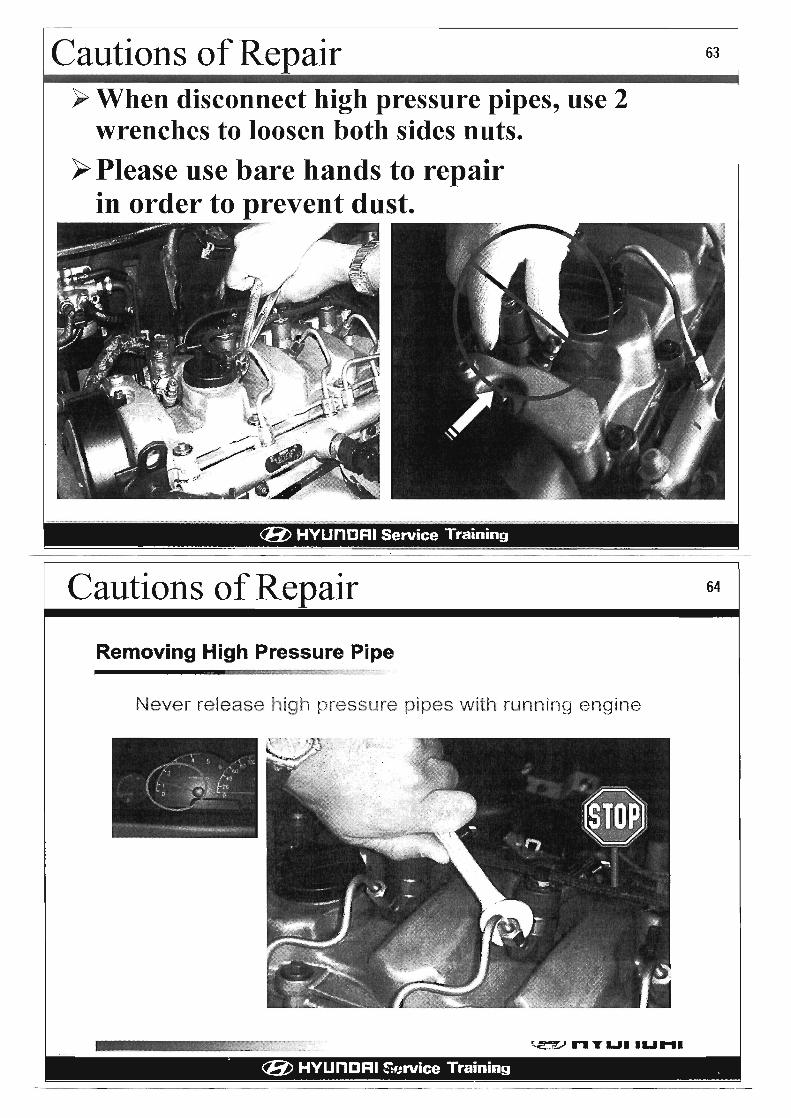
Cautions of Repair
61
ACV G;;I ( Air Control B!!I
Valve)
62
> Every system component should be packed by sealed plastic. Every port should use proper plug to prevent dust.
> Never use air guns to clean engine room when fuel pipes are removed.
Removing and Installing Injectors
y Install Injectors: e Clean the base
eCopper washer
eTorque T40 Torx (torque: 2.70 9.2 kgm)
(/if) HVUnORI ~'<~rvice Training •

2nd Generation CRDi System • CRDi system ( Injection pressure: 1600 bar)
2nd injector High pressure pump
Rail pressure control valve
• Function
• 1600bar high pressure injection => Effectively control the quantity of fuel injection
Injector (multi-injection) • 2nd Injector Cutaway
Multi-injection:
Se(lllng pli'tc
Va!\'o bO<;Jy } Valve V~)I\i~) {lI !::ol 01. gl\'vp
Pilot Injection 2+Pilot Injection l+Main Injection + Secondary Injection 2+ Secondary Injection 1
• Function
Engine start and low idle
area
Characteristic
Pressure I Time
Min injection interval
Min fuel injection quantity
Inaccuracy in Pilot Injection Inaccuracy in Main Injection
2nd GEN INJ
1600 bar 15
0.8ms
1.0 mm3/st
±0.5 mm3/st
±1.0 mm3/st
l ' tGEN INJ
1350 bar/3
1.8 ms
1.5 mm3/st
±0.8 mm3/st
±1.5 mm3/st
• Reduce the min quantity of fuel injection and 1 /3 inaccuracy of pilot injection I main injection.
• Optimal injection in every driving situation.
• Gr Noise I exhaust gas I driving feeling are optimal. 44
rpm

EURO-IV Injection
~ o
'CrS <p I t
Recycle [500°C i]
, ' " ,~~_iJial nje0tion1i6@Quen'ce l'contit)14~)[~if;1»(S~~i~4i'4'!;;j',k~~ , l¥.Ist: 2{l.§i"-'>j<'TJ<ffi .V;;tf;;£."ii "Z:"¥J,", f";''0~~. ~M{;u f¢ ~ ~I!~ -i§"''f'':<'~#'r' -ff¢l«>:;.¥:~ "'1&
~3.~?~~14~.~~i~tJr_1~~I'lfdt[i~,~!!!t~lgPill9~~~f€fi.f~1 J\Jmor4?~s~~tfli. , nee ~ng ," '«$," ,¥, ,'" Aetara 1\ngte '.) 4
Pilot Injection (BTDC) 1000 SOE(PiI1 )+ 150 I..Is + ET(PiI2) Start 2
Pilot Injection (BTDC) 1000 SOE(MI) + 150 I..Is + ET(PiI1) Reduce smoke
1 NVH
Main Injection (BTDC) 400 (ATDC) 400 Increase torque
Secondary SOE(MI) (ATDC) 400 Increase the temperature
Injection 2 + ET(MI) + 150 I..IS of CPF
Secondary (ATDC) 400 Max Ignition advance angle Stimulate catalysis
Injection 1 for next cylinder (Burn the soot)
SOE = Start Of Energizing ; ET = Energizing Time
-----------~----------------------------
IQA (Injector Quantity Adjustment)
WithlQA
• Function
PI Pilot Injection U Low tdle
Energizing Time (tis]
• Reduce the inaccuracy of every injector's injection quantity = > Reduce exhaust gas emission
45 -------,--- ----

IQA (Injector Quantity Adjustment)
46
Cautions of Repair y When disconnect high pressure pipes, use 2
wrenches to loosen both sides nuts.
~ Please use bare hands to repair in order to prevent dust.
(E/) HYUnORI Service Training
63
.
Cautions of Repair 64
Removing High Pressure Pipe
Never release high pressure pipes with running: engine
~"T"""LI"" (E/) HYUnORI S'Jrvice Training . -------------------------

Cautions of Repair 65
Checking fuel pressure & checking injector operation
High pressure can be checked only via the Rail Pressure Sensor Voltage Reading.
High pressure can be checked only via the Raj,1 Pressure Sensor Voltage Reading.
(8;> HVUnCRI (8) HYUnORI Service Training .
48