Embed Size (px)
Citation preview

MAKING MODERN LIVING POSSIBLE
Technical Information
SensorCYPR1 Yaw, Pitch, and Roll
powersolutions.danfoss.com

Revision history Table of revisions
Date Changed Rev
August 2015 First editon 0000
Technical Information CYPR1 Yaw, Pitch, and Roll Sensor
2 BC00000339 • Rev 0000 • August 2015
Product overviewOverview..............................................................................................................................................................................................4Features and options...................................................................................................................................................................... 4Theory of operation.........................................................................................................................................................................4Ordering information......................................................................................................................................................................4
User liability and safety statementsSafety critical applications.............................................................................................................................................................5OEM responsibility........................................................................................................................................................................... 5Machine wiring guidelines............................................................................................................................................................5Machine welding guidelines........................................................................................................................................................ 6
Product installationDimensions......................................................................................................................................................................................... 7Mechanical installation...................................................................................................................................................................7
ConnectorConnector pin assignments..........................................................................................................................................................8
Parameter set-upSource addresses.............................................................................................................................................................................. 9Set the source address....................................................................................................................................................................9Using the PLUS+1® Service Tool................................................................................................................................................10
CAN message protocolsJ1939 message protocol..............................................................................................................................................................11Sensor message data field descriptions................................................................................................................................ 11
Data field summary..................................................................................................................................................................13
SpecificationsElectrical............................................................................................................................................................................................ 16Environmental.................................................................................................................................................................................16Mechanical....................................................................................................................................................................................... 16
Technical Information CYPR1 Yaw, Pitch, and Roll Sensor
Contents
BC00000339 • Rev 0000 • August 2015 3

Overview
The CYPR1 Yaw, Pitch, and Roll Sensor is designed for use as a component in mobile machine controlsystems that require angle measurement.
This sensor uses MEMS (Micro Electro Mechanical System) technology combined with advanced signalprocessing to intelligently cancel out transverse machine motion, providing a high precision, fastresponding, and stable angle measurement in all three axes.
Features and options
• State of the art MEMS technology
• PLUS+1® Compliant GUIDE function block available
• IP 67
• 12 Pin DEUTSCH DTM connector
• CAN 2.0 B compliant
• Supports J1939 and Danfoss proprietary CAN message protocols
• Sensor parameters can be set via the PLUS+1® Service Tool
• Input configuration pin for use of multiple sensors on a single CAN bus
• 9 to 36 Vdc power supply
• Measures slope, angle, and orientation
• CE compliant
Theory of operation
Sensor yaw, pitch, and roll definitions
Ordering information
CYPR1 Yaw, Pitch and Roll Sensor and related products part numbers
Description Danfoss part number
CYPR1 11166660
CG150-2 CAN/USB Gateway 11153051
DEUTSCH mating connector 10102025(16 to 20 AWG)
101000944(20 to 24 AWG)
PLUS+1® GUIDE single user license 10101000
Technical Information CYPR1 Yaw, Pitch, and Roll Sensor
Product overview
4 BC00000339 • Rev 0000 • August 2015
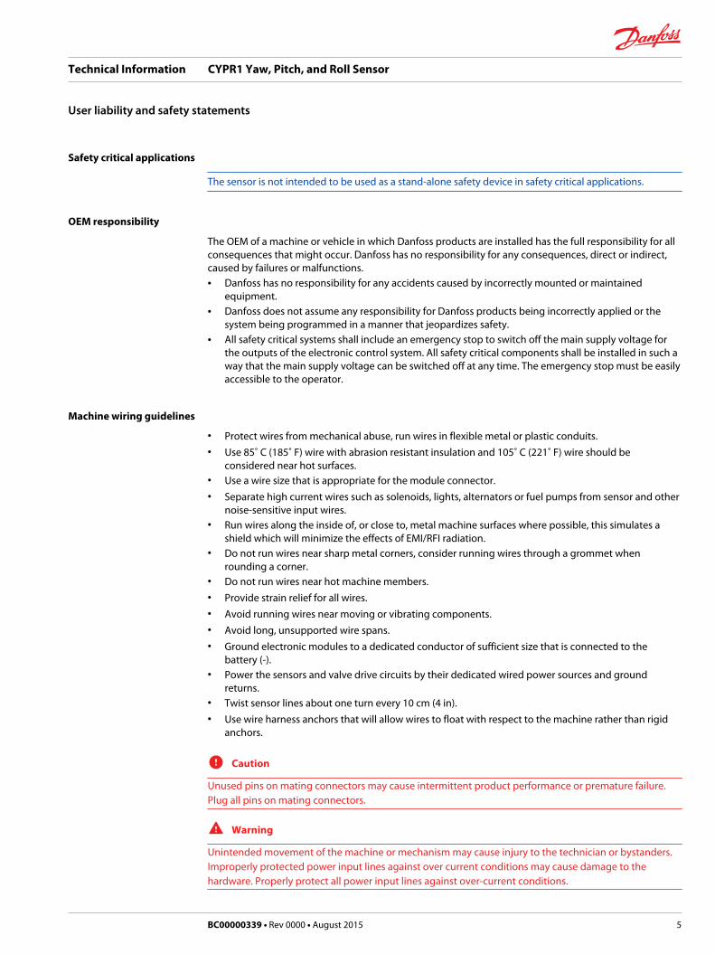
Safety critical applications
The sensor is not intended to be used as a stand-alone safety device in safety critical applications.
OEM responsibility
The OEM of a machine or vehicle in which Danfoss products are installed has the full responsibility for allconsequences that might occur. Danfoss has no responsibility for any consequences, direct or indirect,caused by failures or malfunctions.• Danfoss has no responsibility for any accidents caused by incorrectly mounted or maintained
equipment.• Danfoss does not assume any responsibility for Danfoss products being incorrectly applied or the
system being programmed in a manner that jeopardizes safety.• All safety critical systems shall include an emergency stop to switch off the main supply voltage for
the outputs of the electronic control system. All safety critical components shall be installed in such away that the main supply voltage can be switched off at any time. The emergency stop must be easilyaccessible to the operator.
Machine wiring guidelines
• Protect wires from mechanical abuse, run wires in flexible metal or plastic conduits.• Use 85˚ C (185˚ F) wire with abrasion resistant insulation and 105˚ C (221˚ F) wire should be
considered near hot surfaces.• Use a wire size that is appropriate for the module connector.• Separate high current wires such as solenoids, lights, alternators or fuel pumps from sensor and other
noise-sensitive input wires.• Run wires along the inside of, or close to, metal machine surfaces where possible, this simulates a
shield which will minimize the effects of EMI/RFI radiation.• Do not run wires near sharp metal corners, consider running wires through a grommet when
rounding a corner.• Do not run wires near hot machine members.• Provide strain relief for all wires.• Avoid running wires near moving or vibrating components.• Avoid long, unsupported wire spans.• Ground electronic modules to a dedicated conductor of sufficient size that is connected to the
battery (-).• Power the sensors and valve drive circuits by their dedicated wired power sources and ground
returns.• Twist sensor lines about one turn every 10 cm (4 in).• Use wire harness anchors that will allow wires to float with respect to the machine rather than rigid
anchors.
C Caution
Unused pins on mating connectors may cause intermittent product performance or premature failure.Plug all pins on mating connectors.
W Warning
Unintended movement of the machine or mechanism may cause injury to the technician or bystanders.Improperly protected power input lines against over current conditions may cause damage to thehardware. Properly protect all power input lines against over-current conditions.
Technical Information CYPR1 Yaw, Pitch, and Roll Sensor
User liability and safety statements
BC00000339 • Rev 0000 • August 2015 5

Machine welding guidelines
W Warning
High voltage from power and signal cables may cause fire or electrical shock, and cause an explosion ifflammable gasses or chemicals are present.Disconnect all power and signal cables connected to the display before performing any electrical weldingon a machine.
The following is recommended when welding on a machine equipped with electronic components:• Turn the engine off.• Remove electronic components from the machine before any arc welding.• Disconnect the negative battery cable from the battery.• Do not use electrical components to ground the welder.• Clamp the ground cable for the welder to the component that will be welded as close as possible to
the weld.
Technical Information CYPR1 Yaw, Pitch, and Roll Sensor
User liability and safety statements
6 BC00000339 • Rev 0000 • August 2015

Dimensions
CYPR1 dimensions in millimeters [inches]
114.4 [4.50]
158.2 [6.23]
2 X 25.3 [1.0]
107.0 [4.21]
62.0 [2.44]
35.3 [1.39]
51.6 [2.03]
47.1 [1.85]
144.5 [5.69]
Mechanical installation
The sensor can be installed on any flat surface. It is suggested that 6.0 mm (.25 in) fasteners, torqued to9.49 Nm (7 ft lb), be used. The wire harness to the sensor should be secured 4 to 5 inches from the sensorto help prevent any degraded performance of the sensor.
Technical Information CYPR1 Yaw, Pitch, and Roll Sensor
Product installation
BC00000339 • Rev 0000 • August 2015 7

Connector pin assignments
12 pin connector
2200B12
1
11
2
10
3
9
4
8
5
7
6
Connector
Pin Controller function
C1-P1 Power ground -
C1-P2 Power supply +
C1-P3 CAN +
C1-P4 CAN -
C1-P5 CAN shield
C1-P6 Config
C1-P7 Config ground
C1-P8 Not used
C1-P9 Not used
C1-P10 Not used
C1-P11 Not used
C1-P12 Not used
Use care when wiring mating connector. Above pinouts are for device pins.
Technical Information CYPR1 Yaw, Pitch, and Roll Sensor
Connector
8 BC00000339 • Rev 0000 • August 2015

The sensor’s source address may be configured in one of two ways: Configuration through the use of theconfiguration pin (C1-P6) or through the use of the PLUS+1® Service tool. All other adjustable parametersare serviced only through the PLUS+1® Service tool.
Source addresses
The sensor is capable of achieving 256 distinct source addresses, 31 of which may be selected throughthe use of the configuration pin. The pin can be connected directly to ground (source address 129), leftfloating (last programmed source address) or connected to ground through one of thirty differentresistor values.
The source addresses are checked by the sensor’s microprocessor each time it is powered up. In order tochange the source address via the configuration pin, the sensor must be powered up with theconfiguration input pin connected to the appropriate value resistor. Any changes made to the sourceaddress while the sensor is powered are ignored until power has been cycled.
If, on power up, the source address configured by the resistor differ from the value currently stored in thesensor’s non-volatile (NV) memory then the value in NV memory will be over written with the new sourceaddress, as long as the selected resistor value does not exceed 51,100 Ohms.
Set the source address
The table below defines the allowable source addresses and the required resistor value to achieve eachaddress.
Source address Resistor (Ohms) Source address Resistor (Ohms)
129 0 145 2430
130 76.8 146 2740
131 162 147 3160
132 249 148 3570
133 340 149 4120
134 442 150 4750
135 562 151 5490
136 665 152 6490
137 806 153 7680
138 931 154 9310
139 1100 155 11,500
140 1270 156 14,700
141 1430 157 19,600
142 1650 158 28,700
143 1870 159 51,100
144 2150 No change Open
If a system has multiple sensors of the same type and the configuration input pins are used for setting thesource addresses, it is recommended that all of these sensors use a unique resistance value. It is notrecommended to leave one sensor in the open state.
Technical Information CYPR1 Yaw, Pitch, and Roll Sensor
Parameter set-up
BC00000339 • Rev 0000 • August 2015 9

Using the PLUS+1® Service Tool
All of the sensor’s parameters can be set up using the PLUS+1® Service Tool. The source address can onlybe changed by the PLUS+1® Service Tool if the configuration pin is left open.
Allowable values for parameters
Service Tool signal (sensorparameter)
Allowable values Comments
CANBaudRate 100000, 250000, 500000, 1000000 Factory default = 250K
CANID 0-536870911(0x00-0x1FFFFFFF) The least Significant Bits areoverwritten by the Source AddressValue (factory default = 0x18FFB1SA)
UseExtendedID 0,1 0 = 11 bit mode, 1 = 29 bit mode(factory default = 29 bit)
OutputMode 0, 1, 2, 3, 16, 17 Factory default = 1
SourceAddress 0-255 Factory default = 226
TxPeriod 0-255 ms Factory default = 5
UseJ1939AddressClaim 0,1 Factory default = 1
Technical Information CYPR1 Yaw, Pitch, and Roll Sensor
Parameter set-up
10 BC00000339 • Rev 0000 • August 2015
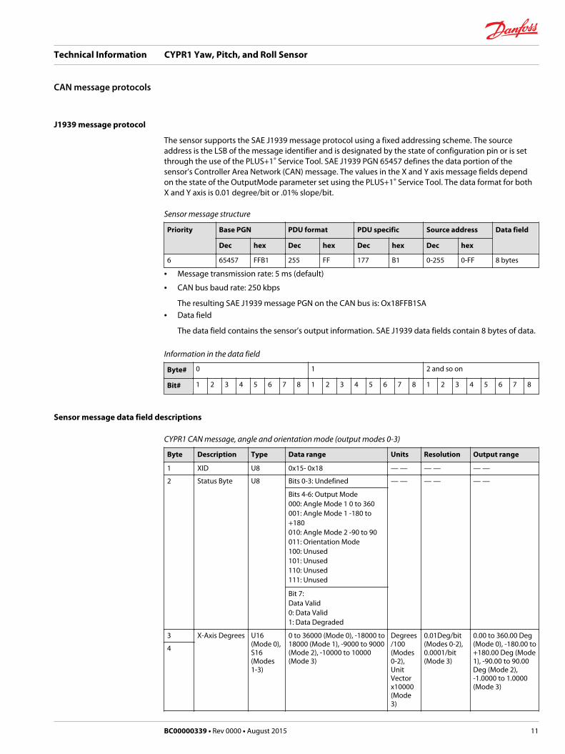
J1939 message protocol
The sensor supports the SAE J1939 message protocol using a fixed addressing scheme. The sourceaddress is the LSB of the message identifier and is designated by the state of configuration pin or is setthrough the use of the PLUS+1® Service Tool. SAE J1939 PGN 65457 defines the data portion of thesensor’s Controller Area Network (CAN) message. The values in the X and Y axis message fields dependon the state of the OutputMode parameter set using the PLUS+1® Service Tool. The data format for bothX and Y axis is 0.01 degree/bit or .01% slope/bit.
Sensor message structure
Priority Base PGN PDU format PDU specific Source address Data field
Dec hex Dec hex Dec hex Dec hex
6 65457 FFB1 255 FF 177 B1 0-255 0-FF 8 bytes
• Message transmission rate: 5 ms (default)
• CAN bus baud rate: 250 kbps
The resulting SAE J1939 message PGN on the CAN bus is: Ox18FFB1SA• Data field
The data field contains the sensor’s output information. SAE J1939 data fields contain 8 bytes of data.
Information in the data field
Byte# 0 1 2 and so on
Bit# 1 2 3 4 5 6 7 8 1 2 3 4 5 6 7 8 1 2 3 4 5 6 7 8
Sensor message data field descriptions
CYPR1 CAN message, angle and orientation mode (output modes 0-3)
Byte Description Type Data range Units Resolution Output range
1 XID U8 0x15- 0x18 — — — — — —
2 Status Byte U8 Bits 0-3: Undefined — — — — — —
Bits 4-6: Output Mode000: Angle Mode 1 0 to 360001: Angle Mode 1 -180 to+180010: Angle Mode 2 -90 to 90011: Orientation Mode100: Unused101: Unused110: Unused111: Unused
Bit 7:Data Valid0: Data Valid1: Data Degraded
3 X-Axis Degrees U16(Mode 0),S16(Modes1-3)
0 to 36000 (Mode 0), -18000 to18000 (Mode 1), -9000 to 9000(Mode 2), -10000 to 10000(Mode 3)
Degrees/100(Modes0-2),UnitVectorx10000(Mode3)
0.01Deg/bit(Modes 0-2),0.0001/bit(Mode 3)
0.00 to 360.00 Deg(Mode 0), -180.00 to+180.00 Deg (Mode1), -90.00 to 90.00Deg (Mode 2),-1.0000 to 1.0000(Mode 3)
4
Technical Information CYPR1 Yaw, Pitch, and Roll Sensor
CAN message protocols
BC00000339 • Rev 0000 • August 2015 11

CYPR1 CAN message, angle and orientation mode (output modes 0-3) (continued)
Byte Description Type Data range Units Resolution Output range
5 Y-Axis Degrees U16(Mode 0),S16(Modes1-3)
0 to 36000 (Mode 0), -18000 to18000 (Mode 1), -9000 to 9000(Mode 2), -10000 to 10000(Mode 3)
Degrees/100(Modes0-2),UnitVectorx10000(Mode3)
0.01Deg/bit(Modes 0-2),0.0001/bit(Mode 3)
0.00 to 360.00 Deg(Mode 0), -180.00 to+180.00 Deg (Mode1), -90.00 to 90.00Deg (Mode 2),-1.0000 to 1.0000(Mode 3)
6
7 Z-Axis Degrees U16(Mode 0),S16(Modes1-3)
0 to 36000 (Mode 0), -18000 to18000 (Mode 1), -9000 to 9000(Mode 2), -10000 to 10000(Mode 3)
Degrees/100(Modes0-2),UnitVectorx10000(Mode3)
0.01Deg/bit(Modes 0-2),0.0001/bit(Mode 3)
0.00 to 360.00 Deg(Mode 0), -180.00 to+180.00 Deg (Mode1), -90.00 to 90.00Deg (Mode 2),-1.0000 to 1.0000(Mode 3)
8
PGN/ID summary
Output mode (d) Data range CAN ID (h) XID (h)
0 0 to 360 degrees 18FFB1SA 15
1 -180 to +180 degrees 18FFB1SA 16
2 -90 to +90 degrees 18FFB1SA 17
3 -1 to + 1 18FFB1SA 18
16 CSS1000 degrees 18FFB1SA 13
17 CSS1000 slope % 18FFB1SA 14
CYPR1 CAN message, CSS1000 compatibility mode (output modes 16-17)
Byte Description Type Data range Units Resolution Output range
1 XID U8 0x13- 0x14 — — — — — —
2 Slope Sensor U8 0x81 — — — — — —
3 X-Axis FOM U8 Bits 0-1: FOM00: Functional01: Degraded10: Error11: NotAvailable
— — — — — —
Bits 2-3: OutputMode00: Unused01: SlopeOutput10: AngleOutput11: NotAvailable
Bits 4-7:Unused
Technical Information CYPR1 Yaw, Pitch, and Roll Sensor
CAN message protocols
12 BC00000339 • Rev 0000 • August 2015

CYPR1 CAN message, CSS1000 compatibility mode (output modes 16-17) (continued)
Byte Description Type Data range Units Resolution Output range
4 Y-Axis FOM U8 Bits 0-1: FOM00: Functional01: Degraded10: Error11: NotAvailable
— — — — — —
Bits 2-3: OutputMode00: Unused01: SlopeOutput10: AngleOutput11: NotAvailable
Bits 4-7:Unused
5 X-Axis %Slopeor Degrees
S16 -5774 to +5774,-3000 to +3000
%Slope,Degrees
0.01%Slope/bit,0.01Deg/bit
-57.74 to +57.74 %, -30 to+30 deg.6
7 Y-Axis %Slopeor Degrees
S16 -5774 to +5774,-3000 to +3000
%Slope,Degrees
0.01%Slope/bit,0.01Deg/bit
-57.74 to +57.74 %, -30 to+30 deg.8
Data field summary
Example: Fixed at 0 x 10
Byte 1
Bit 8 7 6 5 4 3 2 1
SD Byte
Example: Fixed at 0 x 81
Byte 2
Bit 8 7 6 5 4 3 2 1
Slope Sensor Byte
Byte 3
Bit 8 7 6 5 4 3 2 1
Not used Output Mode X axis FOM
X axis FOM information in data field
Bit status Remarks
00 Fully functional; data is within sensor specification.
01 Slope measurement has exceeded specified range..
10 Hardware error
11 Not available
Technical Information CYPR1 Yaw, Pitch, and Roll Sensor
CAN message protocols
BC00000339 • Rev 0000 • August 2015 13

X axis output mode information in data field
Bit status Remarks
00 Not used
01 % slope
10 Degrees
11 Not available
Byte 4
Bit 8 7 6 5 4 3 2 1
Not used Output Mode Y axis FOM
Y axis FOM information in data field
Bit status Remarks
00 Fully functional; data is within sensor specification.
01 Slope measurement has exceeded specified range..
10 Hardware error
11 Not available
Y axis output mode information in data field
Bit status Remarks
00 Not used
01 % slope
10 Degrees
11 Not available
Byte 5
Bit 8 7 6 5 4 3 2 1
X axis LSB
Byte 6
Bit 8 7 6 5 4 3 2 1
X axis MSB
Data range Units Resolution
-18,000 to 18,000 Degrees 0.01 Deg/bit
-32,767 to 32,767 Percent Slope 0.01% Slope/bit
Byte 7
Bit 8 7 6 5 4 3 2 1
Y axis LSB
Technical Information CYPR1 Yaw, Pitch, and Roll Sensor
CAN message protocols
14 BC00000339 • Rev 0000 • August 2015
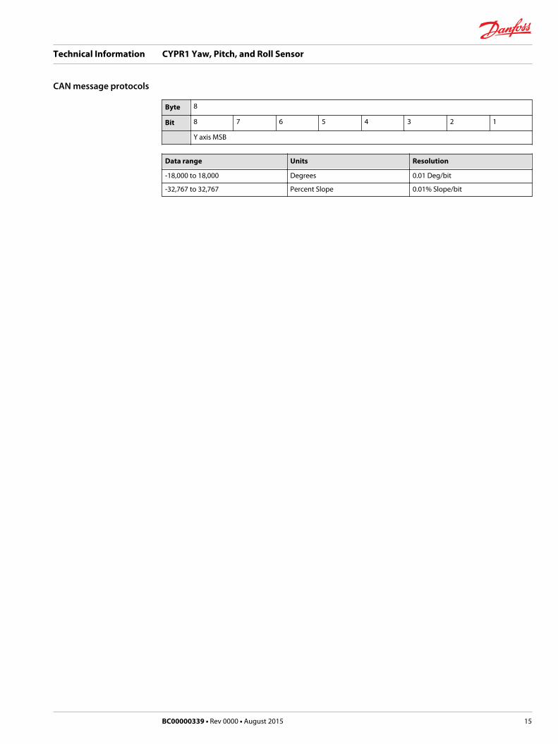
Byte 8
Bit 8 7 6 5 4 3 2 1
Y axis MSB
Data range Units Resolution
-18,000 to 18,000 Degrees 0.01 Deg/bit
-32,767 to 32,767 Percent Slope 0.01% Slope/bit
Technical Information CYPR1 Yaw, Pitch, and Roll Sensor
CAN message protocols
BC00000339 • Rev 0000 • August 2015 15

Electrical
Supply voltage 9 to 36 Vdc
Device maximum power consumption 1.0 Watt
Environmental
Operating temperature range -40° C to 85° C [-40° F to 185° F]
Storage temperature range -40° C to 85° C [-40° F to 185° F]
EMI/RFI rating 150 V/m
Ingress Protection (IP) rating (with mating connector attached)
IP 67
Mechanical
Operation range, degrees ±180°
Resolution, degrees 0.01°
Accuracy, degrees 0.15° typical, 0.25° worst case
Repeatability (hysteresis) degrees 0.05° typical
Accelerometer range 6g
Gyro rate ±125° per second
Weight 0.34 kg (0.75 lbs)
Vibration IEC 60068-2-64
Shock IEC 60068-2-27 test Ea
Technical Information CYPR1 Yaw, Pitch, and Roll Sensor
Specifications
16 BC00000339 • Rev 0000 • August 2015

Technical Information CYPR1 Yaw, Pitch, and Roll Sensor
BC00000339 • Rev 0000 • August 2015 17

Technical Information CYPR1 Yaw, Pitch, and Roll Sensor
18 BC00000339 • Rev 0000 • August 2015

Technical Information CYPR1 Yaw, Pitch, and Roll Sensor
BC00000339 • Rev 0000 • August 2015 19

Danfoss Power Solutions is a global manufacturer and supplier of high-quality hydraulic andelectronic components. We specialize in providing state-of-the-art technology and solutionsthat excel in the harsh operating conditions of the mobile off-highway market. Building onour extensive applications expertise, we work closely with our customers to ensureexceptional performance for a broad range of off-highway vehicles.
We help OEMs around the world speed up system development, reduce costs and bringvehicles to market faster.
Danfoss – Your Strongest Partner in Mobile Hydraulics.
Go to www.powersolutions.danfoss.com for further product information.
Wherever off-highway vehicles are at work, so is Danfoss. We offer expert worldwide supportfor our customers, ensuring the best possible solutions for outstanding performance. Andwith an extensive network of Global Service Partners, we also provide comprehensive globalservice for all of our components.
Please contact the Danfoss Power Solution representative nearest you.
Local address:
Danfoss Power Solutions GmbH & Co. OHGKrokamp 35D-24539 Neumünster, GermanyPhone: +49 4321 871 0
Danfoss Power Solutions ApSNordborgvej 81DK-6430 Nordborg, DenmarkPhone: +45 7488 2222
Danfoss Power Solutions (US) Company2800 East 13th StreetAmes, IA 50010, USAPhone: +1 515 239 6000
Danfoss Power Solutions Trading(Shanghai) Co., Ltd.Building #22, No. 1000 Jin Hai RdJin Qiao, Pudong New DistrictShanghai, China 201206Phone: +86 21 3418 5200
Danfoss can accept no responsibility for possible errors in catalogues, brochures and other printed material. Danfoss reserves the right to alter its products without notice. This also applies toproducts already on order provided that such alterations can be made without changes being necessary in specifications already agreed.All trademarks in this material are property of the respective companies. Danfoss and the Danfoss logotype are trademarks of Danfoss A/S. All rights reserved.
BC00000339 • Rev 0000 • August 2015 www.danfoss.com © Danfoss A/S, 2015
Products we offer:
• Bent Axis Motors
• Closed Circuit Axial PistonPumps and Motors
• Displays
• Electrohydraulic PowerSteering
• Electrohydraulics
• Hydraulic Power Steering
• Integrated Systems
• Joysticks and ControlHandles
• Microcontrollers andSoftware
• Open Circuit Axial PistonPumps
• Orbital Motors
• PLUS+1® GUIDE
• Proportional Valves
• Sensors
• Steering
• Transit Mixer Drives
Comatrolwww.comatrol.com
Schwarzmüller-Inverterwww.schwarzmueller-inverter.com
Turolla www.turollaocg.com
Hydro-Gearwww.hydro-gear.com
Daikin-Sauer-Danfosswww.daikin-sauer-danfoss.com