Embed Size (px)
Citation preview

8/3/2019 Cypercat 254 Cutsheet
http://slidepdf.com/reader/full/cypercat-254-cutsheet 1/8
FIK E CYBERCAT™ 25 4INT ELLIGENT FIRE ALARM CONTROL SYSTEM
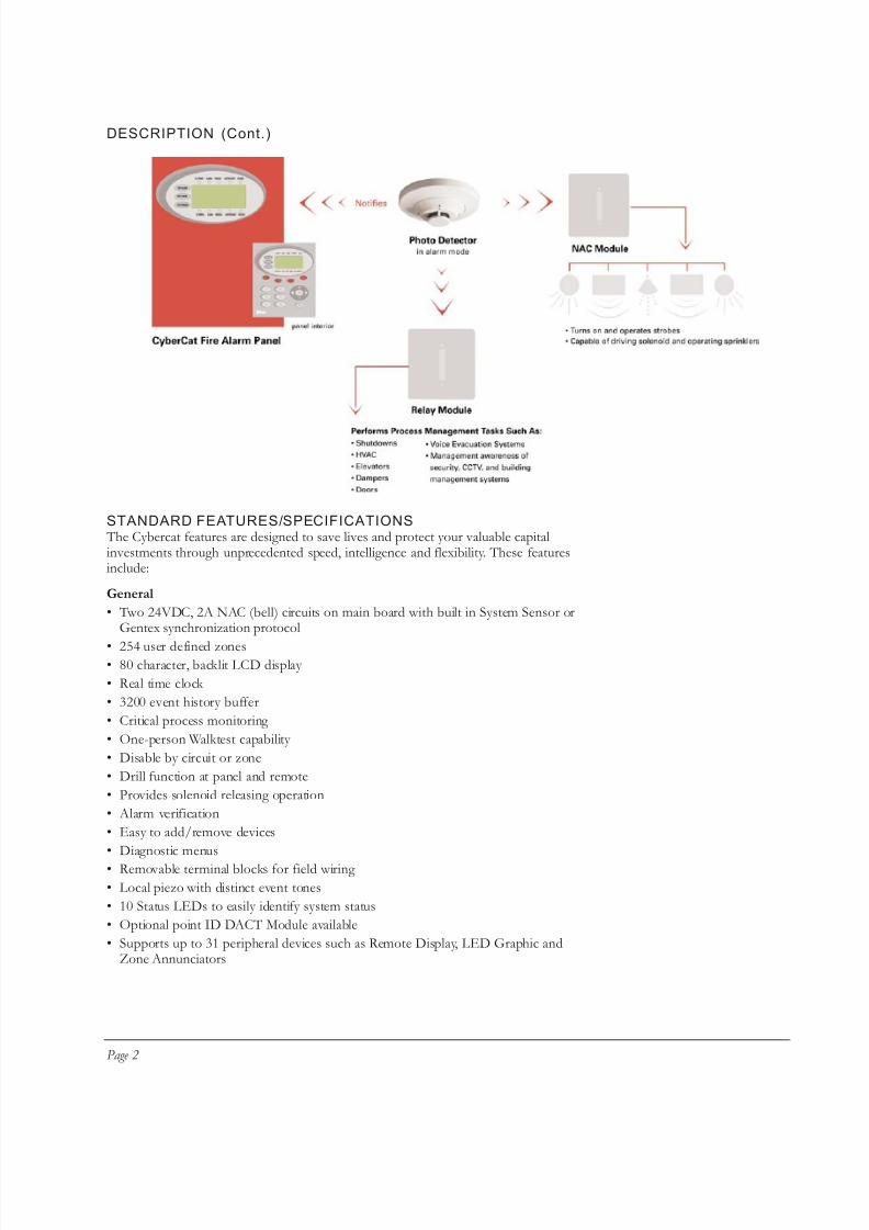
DESCRIPTIONFike's CyberCat 254 (P/N 10-066) is a state-of-the-art true intelligent digital peer-to-peer modular fire alarm control system. It is ideal for all life safety andproperty protection applications and is intended for both commercial andindustrial use. It is designed with extensive programmability that allows thealmost-instantaneous relay of information and the ability to perform processmanagement tasks with ease including shutdowns, HVAC, Voice EvacuationSystems, Dampers, Doors, Elevators, and Security, CCTV/Building Management Awareness.
This cost-effective panel comes standard with one Signaling Line Circuit (SLC)that supports 254 devices. The 254 devices may be any mix and match of sensorsand modules. The CyberCat utilizes extreme intelligence via its eclipse basedsensors including photoelectric, photoelectric with heat, ionization, photoelectric
duct, and heat detectors. It also utilizes Eclipse™ based modules such as themonitor, mini-monitor, relay, intelligent pull station and control modules. WithCyberCat every device communicates as a peer on the signaling line circuit. Thesepeers not only communicate up-to-the-second information to the control panel,but also communicate with each other. Each device is capable of generating accurate and highly detailed information. Conventional fire alarm systems give ageneral idea of the fire's location, while the CyberCat's intelligent sensors indicateprecisely which device is in an alarm state. This intelligence provides incrediblespeed with response times as little as one-quarter second between manual pullstation and notification appliance. Its flexibility allows you to attach the intelligentdevices that are required for your specific application.
The System is programmed with either the Windows based field configurationsoftware C-LINX TM or through a comprehensive password protected front-panel
keypad programming options. This option allows you to quickly update and adaptto any future requirements or changes in the system such as changes inoccupancy or remodeling. The sophisticated control panel circuitry coupled withthe software allows you to read specific information and sensitivity levels of thedifferent Eclipse devices. The sensors also compensate for any changes due toage, contamination, or other environmental factors.
System Operation
The CyberCat Control system operates on a "Zone and State" relationship. In thisdesign, all input and output devices must be assigned to at least one zone or to allzones (254 are available), each one defining an area to be protected. Input devicescan be assigned up to four zones (one zone is typical) and output devices may beconfigured for up to 254 zones.
These devices use the SLC signaling line circuits to exchange status information with other devices as well as with the control panel. When an input is activated, itis configured to cause its associated zone to enter into an operational state. Any detection device will cause its associated zone to enter into an alarm state. Theoutput devices are configured to activate to protect and evaluate the endangeredzone. This system is completely modular, allowing you the flexibility to design asystem that is just right for your application. A typical configuration is shown onpage 2 that illustrates the communications of a CyberCat system.
704 S. 10th Street · P.O. Box 610 · Blue Springs, Missouri 64013-0610 U.S.A. · (816) 229-3405 · (816) 229-4615 · www.fike.com
APPROVALS
• UL S2203
• FM 3020297• City of Denver
• CSFM 7165-0900: 137
Fike Cybercat 254
Form No. D.1.09.01-4
8/3/2019 Cypercat 254 Cutsheet
http://slidepdf.com/reader/full/cypercat-254-cutsheet 2/8
DESCRIPTION (Cont.)
STANDARD FEATURES/SPECIFICATIONS The Cybercat features are designed to save lives and protect your valuable capitalinvestments through unprecedented speed, intelligence and flexibility. These featuresinclude:
General
• Two 24VDC, 2A NAC (bell) circuits on main board with built in System Sensor orGentex synchronization protocol
• 254 user defined zones• 80 character, backlit LCD display
• Real time clock
• 3200 event history buffer
• Critical process monitoring
• One-person Walktest capability
• Disable by circuit or zone
• Drill function at panel and remote
• Provides solenoid releasing operation
• Alarm verification
• Easy to add/remove devices
• Diagnostic menus
• Removable terminal blocks for field wiring
• Local piezo with distinct event tones
• 10 Status LEDs to easily identify system status
• Optional point ID DACT Module available
• Supports up to 31 peripheral devices such as Remote Display, LED Graphic andZone Annunciators
Page 2
8/3/2019 Cypercat 254 Cutsheet
http://slidepdf.com/reader/full/cypercat-254-cutsheet 3/8
STANDARD FEATURES/SPECIFICATIONS (Cont .)
Power
• 6 amps useable alarm power
• Operation from 120VAC/60 Hz or 240 VAC/50 Hz
• Two 24V DC, 2A continuous auxiliary power outputs• One 24VDC, 2A resettable auxiliary power output
• Supports up to 75AH of batteries
Signaling Line Circuit
• Address devices with Infrared (IR) tool, similar to remote control device
• One SLC loop, NFPA style 4 or 6
• 254 devices
• True peer-to-peer digital protocol for extremely fast and reliable communications
• Auto address function
• Automatic day/night sensitivity adjustment
• Automatic holiday sensitivity adjustment
• Acclimate operation for sensors
• IR Tool provides ability to read sensitivity levels or perform remote test of device
• Devices contain multi-color LED for quick reference of device status
• Sensors provide early warning pre-alarm detection and can also provide a summing feature (up to eight sensors)
NAC Circuit
• Two NAC circuits standard
• Rated at 24VDC, 2.0 Amps maximum
• Built-in synch protocol for System Sensor®, Gentex®, and Wheelock® devices
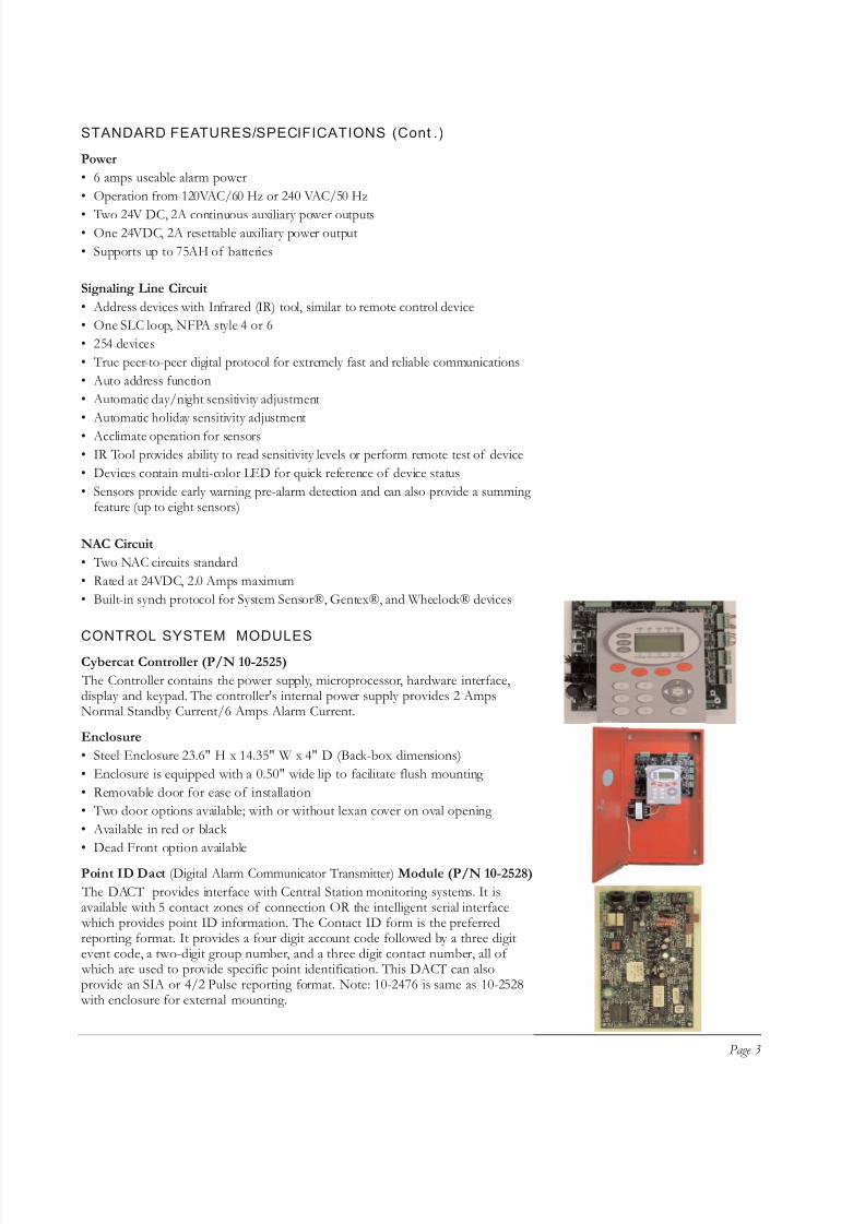
CONTROL SYSTEM MODULESCybercat Controller (P/N 10-2525)
The Controller contains the power supply, microprocessor, hardware interface,display and keypad. The controller's internal power supply provides 2 AmpsNormal Standby Current/6 Amps Alarm Current.
Enclosure
• Steel Enclosure 23.6" H x 14.35" W x 4" D (Back-box dimensions)
• Enclosure is equipped with a 0.50" wide lip to facilitate flush mounting
• Removable door for ease of installation
• Two door options available; with or without lexan cover on oval opening
• Available in red or black
• Dead Front option available
Point ID Dact (Digital Alarm Communicator Transmitter) Module (P/N 10-2528)
The DACT provides interface with Central Station monitoring systems. It isavailable with 5 contact zones of connection OR the intelligent serial interface which provides point ID information. The Contact ID form is the preferredreporting format. It provides a four digit account code followed by a three digitevent code, a two-digit group number, and a three digit contact number, all of which are used to provide specific point identification. This DACT can alsoprovide an SIA or 4/2 Pulse reporting format. Note: 10-2476 is same as 10-2528 with enclosure for external mounting.
Page 3

8/3/2019 Cypercat 254 Cutsheet
http://slidepdf.com/reader/full/cypercat-254-cutsheet 4/8
CONTROL SYSTEM MODULES (Cont .)
Fike Relay Module (P/N 10-2204)
The CRM4 provides 4 additional independently programmed relays. CyberCat ControlPanel supports up to 2 CRM4 modules (if either options are not unused) on the maincontroller board. Each relay may be wired across normally open or normally closed
contacts. Dimensions: 3-1/2" L x 1-1/2" H x 2" D. Weight: 0.10 lbs.
Fike Reverse Polarity Module (CRPM) (P/N 10-2254)
The reverse polarity module provides the ability for UL Remote Station supervision. Thissupervision is typically performed with a direct, leased line connection. It interfaces to themain control board using four standoffs supplied with the RPM.Dimensions: 3-1/2" L x 1-1/2" H x 2" D. Weight: 0.08 lbs.
Fike Remote LCD Display (P/N 10-2321)
This module provides information about the host CyberCat System in a remote location.It receives the intelligent data stream from the RS485 output of the CyberCat. The remotedisplay provides the capability to remotely reset, silence, and acknowledge the main controlpanel. Security to the unit is available via the standard Fike key. It mounts to a 5 gang masonry box (Raco 694). The unit can be surface or flush mounted.Dimensions: 9-7/32" L x 3-3/4" H x 2-1/2" D. Weight: 2 lbs.
Fike Zone Annunciator (P/N 10-2373)
The Zone Annunciator provides instant visual status of up to 10 zones of fire protection.Each zone has a red Alarm LED and yellow Trouble/Supervisory LED. Each LED isindividually programmable for zone(s) and state(s). Each LED can be labeled using Avery Label 6467 or 5418. The annunciator also has an internal piezo to provide instant audiblenotification of status change. It is intended to be powered via the CyberCat panel 24VDCauxiliary power. It communicates with the main control panel via RS485 communication. The annunciator provides the capability to remotely reset, silence and acknowledge themain control panel. Security to the unit is available via the standard Fike key. It mounts toa 5 gang masonary box (Raco 694). The unit can then be surface or flush mounted.
The following system modules are available for the CyberCat Control System:
Fike Network Module (P/N 10-2482)
The Network Module provides the ability to network up to 128 control panels. Thistypically would consist of other CyberCat fire alarm panels. The CyberCat network uses a
"common zone" functionality. Zones 1-254 are common to all panels on the network andany input will cause activation of all outputs for the same zone, regardless of which panel
the devices are connected to. Regardless of zone number, every state (alarm, trouble etc.)that occurs is displayed by all panels on the network.
Part Number Description
10-064-c-p-d CyberCat System-Includes Controller, Enclosure, and Transformer c:(R=Red, B=Black) p:(1=120V, 2=240V)d:(B=Blank; L= Lexan)
10-2525 Cybercat System Controller (included with 10-066-c-p-d)
10-2528 DACT, 5 zone with Serial interface
10-2204 CRM4 - Relay Module
10-2254 CRPM - Reverse Polarity Module
10-2321 FIKE Remote Display
10-2373 Zone Annunciator
10-2482 Network Module
10-11x LED Graphic
10-2519-c Dead Front Option c: (R=Red, B=Black)
Page 4

8/3/2019 Cypercat 254 Cutsheet
http://slidepdf.com/reader/full/cypercat-254-cutsheet 5/8
CYBERCAT/PROGRAMMIN G CONFIGURATION
Software
All configuration variables can be assigned using C-LINX software. Thissoftware provides the designer the capability to provide a pre-engineered
design. The user can review the construction plans to assign the zones. Theconfiguration can also be set to identify the exact device circuit operationdesired along with the custom message information.
IR Configuration Tool
This optional hand-held infrared remote control is available on the CyberCatsystem. This small device can be used in the field to simplify installation,testing and service. It operates with 2 AA batteries and can read deviceinformation such as loop, address, branch and service dates and initiate devicetest. This tool:
• Communicates bi-directionally with any CyberCat device
• Easily addresses devices by setting the loop and address
• Quickly reads sensitivity levels, date serviced, device type, loop and address,
manufacture date• Immediately records the date serviced
• Instantly initiates walk test of any sensor or module
• Accesses and tests hard-to-reach sensor or module (such as duct detector)through any other device on loop
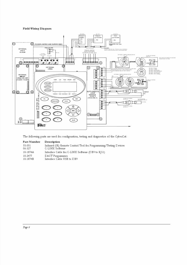
Field Wiring
Although the installation instructions provided for each module should be usedfor installation, please see the a general wiring diagram on the following page.
Wiring Specifications
• Maximum Resistance: 70 ohms
• Maximum Capacitance: .06 uf • 12,000 ft. maximum distance total from panel to last device.
Page 5
8/3/2019 Cypercat 254 Cutsheet
http://slidepdf.com/reader/full/cypercat-254-cutsheet 6/8
8/3/2019 Cypercat 254 Cutsheet
http://slidepdf.com/reader/full/cypercat-254-cutsheet 7/8
CYBERCAT INTELLIGENT DEVICES
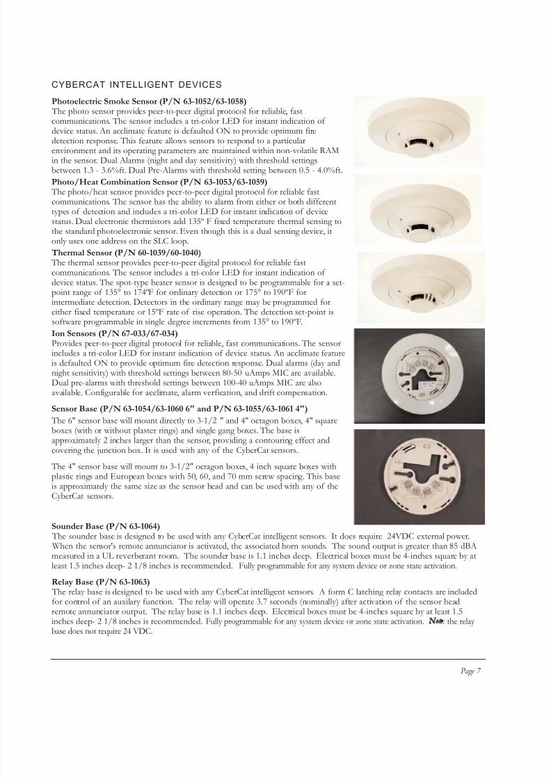
Photoelectric Smoke Sensor (P/N 63-1052/63-1058) The photo sensor provides peer-to-peer digital protocol for reliable, fastcommunications. The sensor includes a tri-color LED for instant indication of device status. An acclimate feature is defaulted ON to provide optimum firedetection response. This feature allows sensors to respond to a particularenvironment and its operating parameters are maintained within non-volatile RAMin the sensor. Dual Alarms (night and day sensitivity) with threshold settingsbetween 1.3 - 3.6%ft. Dual Pre-Alarms with threshold setting between 0.5 - 4.0%ft.
Photo/Heat Combination Sensor (P/N 63-1053/63-1059) The photo/heat sensor provides peer-to-peer digital protocol for reliable fastcommunications. The sensor has the ability to alarm from either or both differenttypes of detection and includes a tri-color LED for instant indication of devicestatus. Dual electronic thermistors add 135º F fixed temperature thermal sensing tothe standard photoelectronic sensor. Even though this is a dual sensing device, itonly uses one address on the SLC loop.
Thermal Sensor (P/N 60-1039/60-1040) The thermal sensor provides peer-to-peer digital protocol for reliable fast
communications. The sensor includes a tri-color LED for instant indication of device status. The spot-type heater sensor is designed to be programmable for a set-point range of 135° to 174ºF for ordinary detection or 175° to 190ºF forintermediate detection. Detectors in the ordinary range may be programmed foreither fixed temperature or 15ºF rate of rise operation. The detection set-point issoftware programmable in single degree increments from 135° to 190ºF.
Ion Sensors (P/N 67-033/67-034)Provides peer-to-peer digital protocol for reliable, fast communications. The sensorincludes a tri-color LED for instant indication of device status. An acclimate featureis defaulted ON to provide optimum fire detection response. Dual alarms (day andnight sensitivity) with threshold settings between 80-50 uAmps MIC are available.Dual pre-alarms with threshold settings between 100-40 uAmps MIC are alsoavailable. Configurable for acclimate, alarm verfication, and drift compensation.
Sensor Base (P/N 63-1054/63-1060 6" and P/N 63-1055/63-1061 4") The 6" sensor base will mount directly to 3-1/2 " and 4" octagon boxes, 4" squareboxes (with or without plaster rings) and single gang boxes. The base isapproximately 2 inches larger than the sensor, providing a contouring effect andcovering the junction box. It is used with any of the CyberCat sensors.
The 4" sensor base will mount to 3-1/2" octagon boxes, 4 inch square boxes withplastic rings and European boxes with 50, 60, and 70 mm screw spacing. This baseis approximately the same size as the sensor head and can be used with any of theCyberCat sensors.
Page 7
Sounder Base (P/N 63-1064) The sounder base is designed to be used with any CyberCat intelligent sensors. It does require 24VDC external power.
When the sensor's remote annunciator is activated, the associated horn sounds. The sound output is greater than 85 dBAmeasured in a UL reverberant room. The sounder base is 1.1 inches deep. Electrical boxes must be 4-inches square by atleast 1.5 inches deep- 2 1/8 inches is recommended. Fully programmable for any system device or zone state activation.
Relay Base (P/N 63-1063) The relay base is designed to be used with any CyberCat intelligent sensors. A form C latching relay contacts are includedfor control of an auxilary function. The relay will operate 3.7 seconds (nominally) after activation of the sensor headremote annunciator output. The relay base is 1.1 inches deep. Electrical boxes must be 4-inches square by at least 1.5inches deep- 2 1/8 inches is recommended. Fully programmable for any system device or zone state activation. Not e : the relay base does not require 24 VDC.

8/3/2019 Cypercat 254 Cutsheet
http://slidepdf.com/reader/full/cypercat-254-cutsheet 8/8
INTELLIGENT MODULESFike's intelligent modules provide a fire alarm dry contact device directly connected to theCyberCat intelligent loop. Each module may be assigned to a single zone or up to fourzones. Any number of UL listed contact closure devices may be used.
Mini-Monitor Module (55-045/55-050)
2-3/4" x 1-3/4" miniature module for mounting in the small junction box behind amonitoring device. This device will monitor a Class B wired input device using the 39K ohm end of the line resistor.
4" Square Monitor Module (55-041/55-046)
Mounted with cover plate on a 4" square junction box. This device will monitor a Class Bor Class A wired input device. Class B wiring requires a 39K ohm end of line resistor.
Pull Station Monitor Module (P/N 20-1063/20-1064)
The intelligent pull station has all of the same addressable input module electronics insidethe pull station for one complete addressable pull station. Activation is accomplished by pushing in and pulling down as instructed. A hardware key is issued to reset the device.
Supervised Control Module (P/N 55-042/55-047)
The Supervised Control Module (SCM) provides building notification appliance circuits(NAC), an intelligent interface to the CyberCat Intelligent loop. It also has the capability of operating solenoids rated up to 2 Amps @ 24VDC or two @ 12VDC in series. Mounts in a4" x 4" x 2-1/8" junction box. Wide range of multi-state operations.
Relay Module (P/N 55-043/55-048)
The Relay Module provides building dry contact output interface via the intelligent loop. Two configurable (single operation) relay Form C contacts rated for 2 Amps @ 30VDC,0.5a @ 120VAC. Wide range of operating modes including multi-zone operation, up to 4different states and multi-state programming. Operating parameters are maintained in non-
volatile RAM for quick and reliable response to emergency conditions. This module mountson a 4" x 4" x 2-1/8" junction box. Not e : the relay module does not require 24 VDC.
Duct Sensor (Sensor is P/N 63-1057/63-1062; Housing is P/N 63-1056)
The Duct Housing contains a circuit board that provides connection to standard remoteaccessories and also provides a relay contact output is fully programmable and transfersupon activation of the DUCT detector.. Four different lengths of sampling tube areavailable for duct penetration including 1.5, 3.0, 5.0 and 10.0. Not e: the duct sensor does notrequire 24 VDC.
Length Part Number
1.5' 02-3721
3.0' 02-3722
5.0' 02-3723
10.0' 02-3724
Copyright © Fike Corporation All Rights Reserved.Form No. D.1.09.01-4 December, 2005 Specifications are subject to change without notice.
System Sensor, Gentex, and Wheelock are trademarks or registered trademarks. ©Copyright 2005.