Embed Size (px)
Citation preview

Cycling by Design 2010

Cycling by Design 2010 (Revision 1, June 2011)
Cycling by Design 2010 (Revision 1, June 2011)
© Crown copyright 2011 You may re-use this information (excluding logos) free of charge in any format or medium, under the terms of the Open Government Licence. To view this licence, visit http://www.nationalarchives.gov.uk/doc/open-government-licence/ or e-mail: [email protected] Where we have identified any third party copyright information you will need to obtain permission from the copyright holders concerned. Any enquiries regarding this document should be sent to us at the address on the following page. This document is also available on our website at http://www.transportscotland.gov.uk ISBN: 978-1-906006-68-6 Published by Transport Scotland, June 2011

Cycling by Design 2010 (Revision 1, June 2011)
Cycling by Design 2010 (Revision 1, June 2011)
Comments Cycling by Design will be updated regularly to take account of project experience and changes to the legal or design environment. Any comments on the document should be sent to the following address: Susan Bakr Transport Scotland Major Transport Infrastructure Projects Standards, Traffic and Economics Branch Buchanan House 58 Port Dundas Road Glasgow G4 0HF Email: [email protected]

Cycle by Design 2010 (Revision 1, June 2011)
Cycling by Design 2010 (Revision 1, June 2011)
Page intentionally left blank

Cycling by Design 2010 (Revision 1, June 2011) Amendments
Cycling by Design 2010 (Revision 1, June 2011)
Amendments sheet Revision number, Date
Amendment
Revision 1, June 2011
Chapter 7: Junctions and Crossings: • Figure 7.4: crossing detail amended.
• New figure added – crossing of side road using refuge islands, with vehicle priority. This figure becomes Figure 7.9 and subsequent figures re-numbered from previous version as follows:
• Figure 7.9 now Figure 7.10
• Figure 7.10 now Figure 7.11
• Figure 7.11 now Figure 7.12
• Figure 7.12 now Figure 7.13
• Figure 7.13 now Figure 7.14
• Figure 7.14 now Figure 7.15
• Figure 7.15 now Figure 7.16
• Figure 7.16 now Figure 7.17
• Figure 7.13 (previously Figure 7.12): change of detail to clarify that give way markings should not be installed on top of tactile paving.
Chapter 10: Construction and Maintenance: • Chapter amended to provide clarity on rural and urban situations

Cycling by Design 2010 (Revision 1, June 2011)
Cycling by Design 2010 (Revision 1, June 2011)
Page intentionally left blank

Cycling by Design 2010 (Revision 1, June 2011) Contents
Cycling by Design 2010 (Revision 1, June 2011)
Contents 1 Introduction ……………………………………………………… 1 2 Planning for Cyclists ……………………………………………. 7 3 Geometric Design ……………….………………………………. 25 4 Traffic Volume and Speed …….……………………………….. 33 5 Allocating Carriageway Space ………………………………… 47 6 Off-Carriageway Facilities ……………………………………… 59 7 Junctions and Crossings ………...……………………………. 79 8 Cycle Parking ……………………….……………………………. 107 9 Public Transport Integration …….…………………………….. 117 10 Construction and Maintenance ….……………………………. 125 11 Cycle Audit System……………..….……………………………. 135
Appendix A Legal Issues ………………………………………………… A1 Appendix B Signs and Markings………………………………………… B1 Bibliography

Contents Cycle by Design 2010 (Revision 1, June 2011)
Cycling by Design 2010 (Revision 1, June 2011)
Page intentionally left blank
Cycling by Design 2010 (Revision 1, June 2011) Introduction
1 Introduction 1.1 Document Status..........................................................................1 1.2 Benefits of Cycling.......................................................................1 1.3 The National Cycle Network........................................................2 1.4 Application of Guidance..............................................................3 1.5 Definition of Cycle Facilities .......................................................5 List of Figures Figure 1.1: National Cycle Network route map ................................................................4
Cycling by Design 2010 (Revision 1, June 2011)

Introduction Cycling by Design 2010 (Revision 1, June 2011)
Cycling by Design 2010 (Revision 1, June 2011)
Page intentionally left blank

Cycling by Design 2010 (Revision 1, June 2011) Introduction
1 Introduction Cycling by Design was originally published in 1999, having been developed by Scotland’s national and local road authorities and cycling groups. The document was designed to draw together and rationalise existing international cycle design guidelines into a single comprehensive reference document which could be used as a source of sound technical advice.
Comments on the 1999 version were invited and received from cycling interest groups, local authorities, national agencies, members of the public and consultants. Since first publication, further international sources of guidance have been produced and feedback has been received from the many cycling projects delivered across Scotland. This 2010 version of Cycling by Design takes cognisance of the responses received, as well as contemporary sources of guidance and best practice. It also incorporates legislative requirements on ‘Inclusive Design’ with regard to the new public sector equality duty.
Feedback remains of importance to the evolution of the document and practitioners and others are encouraged to submit comments using the contact details at the front of this document.
1.1 Document Status Cycling by Design is published by Transport Scotland for use by practitioners throughout Scotland. The primary focus of the document is the establishment of guidance to ensure consistent and appropriate design.
Transport Scotland requires consultants and contractors working on trunk road projects to follow the guidance within Cycling by Design.
It is commended to local authorities and others developing cycling infrastructure in Scotland. S
ourc
e: C
yclin
g S
cotla
nd
1.2 Benefits of Cycling Cycling contributes towards national and local policy objectives to reduce emissions, tackle congestion, increase tourism and improve physical and mental health. Cycling also aids accessibility and social inclusion objectives. Application of the guidance in Cycling by Design will assist towards these policy objectives.
Cycling by Design 2010 (Revision 1, June 2011) 1

Introduction Cycling by Design 2010 (Revision 1, June 2011)
1.3 The National Cycle Network The National Cycle Network (NCN) comprises over 20,000km of dedicated cycle routes across the UK, of which over 3,000km are in Scotland. Over 400 million walking and cycling trips were made on the NCN in 2009.
The aims of the NCN are to:
• Provide a nationwide network of safe, attractive, high quality routes for all non-motorised users, including pedestrians, cyclists and wheelchair users;
• Promote walking and cycling as forms of transport which link communities and public transport options; and
• Stimulate wider measures benefiting pedestrians and cyclists and help promote local and regional networks.
In Scotland the network is promoted and developed by Sustrans in partnership with national and local road and planning authorities, Forestry Commission Scotland, British Waterways Scotland, Scottish Natural Heritage, National Park Authorities, landowners and other bodies. Online maps and details of route numbering are available at http://www.sustrans.org.uk/what-we-do/national-cycle-network
2 Cycling by Design 2010 (Revision 1, June 2011)
.
A key element in taking the NCN forward is to ensure that it provides convenient, inclusive access for active and sustainable travel. As such, it is important that all NCN partner bodies are engaged in developing the network and in linking it with wider area transport and planning initiatives.
All opportunities should be taken by road and planning authorities and others to:
Sou
rce:
Joh
n G
rimsh
aw
Sou
rce:
Sus
trans
• Actively endeavour to link the NCN to communities;
• Integrate the network with other transport and social infrastructure; and
• Expand local and regional cycle networks to link with the NCN.
Typically NCN routes are a mix of shared use paths free from motorised traffic, segregated routes through towns, redetermined rural footways and quiet roads. Where there is no practical alternative, the NCN may interface with and cross busy trunk roads.

Cycling by Design 2010 (Revision 1, June 2011) Introduction
Transport Scotland takes an active role in delivering key NCN and other routes that interface with the Trunk Road network. The Trunk Road Cycling Initiative requires that, wherever practicable, measures to benefit non-motorised users are incorporated into road improvements.
The NCN is designated and constructed to an appropriate standard to attract a wide range of users and abilities:
Sou
rce:
Cog
& W
heel
• All novice cyclists (aged 12 years and above);
• A competent 12 year old child cycling unaccompanied; and
• Family groups with younger, supervised children.
Development of the National Cycle Network
Sustrans requires the partnership and co-operation of road and planning authorities, countryside, waterway and forestry organisations, charitable trusts, landowners and the general public if the aims of the National Cycle Network are to be achieved. In line with Government policy, road and planning authorities should assist Sustrans with statutory procedures and technical advice including land purchase, order procedures, design and construction services, adoption and maintenance wherever necessary.
Project management advice should also be made available in the context of contemporary experience of road infrastructure procurement, as should general advice when requested.
National and local road and planning authorities should consult Sustrans on any proposed alterations to the NCN, for example, developer-led infrastructure schemes that may offer opportunities to expand the Network.
1.4 Application of Guidance This document sets out ‘Desirable Minimum’ and ‘Absolute Minimum’ guidance. In some instances ‘limiting’ guidance is also used, which is defined where relevant.
Whilst designers should always aim to provide high quality facilities which exceed guidance, the ‘Desirable Minimum’ should be considered as the minimum design requirement providing a good quality of facility.
The ‘Absolute Minimum’ may be applied where there are constraints that mean the Desirable Minimum design guidance cannot be met, for cost, environmental or social reasons.
It is the responsibility of the scheme designer to examine the circumstances of each situation and determine what is appropriate, where minimum guidance may be tolerable and whether or not mitigation may be required in applying such guidance.
Cycling by Design 2010 (Revision 1, June 2011) 3

Introduction Cycling by Design 2010 (Revision 1, June 2011)
Figure 1.1: National Cycle Network route map
N.B. Although there are no NCN routes, the Western Isles offer some of the best quiet-road cycling in Scotland, with
frequent connectivity to mainland Scotland by ferry.
4 Cycling by Design 2010 (Revision 1, June 2011)
Cycling by Design 2010 (Revision 1, June 2011) Introduction
Cycling by Design 2010 (Revision 1, June 2011) 5
1.5 Definition of Cycle Facilities For the purpose of this document, the following non-statutory definitions of cycle facilities are used:
• Cycle lane – Part of the cross section of the trafficked road carriageway intended for use by cyclists only;
• Cycleway – Part of the cross section of a road, but separate from the trafficked carriageway. Pedestrians and cyclists may share a cycleway or may be segregated from each other; and
• Cyclepath – A route for pedestrians and cyclists not associated with a road carriageway. Pedestrians and cyclists may share the cyclepath or may be segregated from each other.

Introduction Cycling by Design 2010 (Revision 1, June 2011)
6 Cycling by Design 2010 (Revision 1, June 2011)
Page intentionally left blank

Cycling by Design 2010 (Revision 1, June 2011) Planning for Cyclists
2 Planning for Cyclists 2.1 Cyclists’ Needs.............................................................................7 2.1.1 Skill Levels.................................................................................................7
2.2 Principles of Design.....................................................................9 2.1.2 Trip Purpose..............................................................................................7
2.2.1 Core Design Principles .............................................................................92.2.2 Hierarchy of Measures..............................................................................9
2.2.3.1 Route Hierarchy ...................................................................................................12 2.2.3 Link Specification Guide .........................................................................11
2.3 Network Planning and Development Process....................... 12 2.3.1 Set Objectives .........................................................................................13
2.3.2.1 Modelling Techniques..........................................................................................13 2.3.2 Assess Demand......................................................................................13
2.3.2.2 Data Sources........................................................................................................14 2.3.2.3 Latent Demand and Barriers ...............................................................................14
2.3.3.1 Existing Cycle Facilities .......................................................................................15 2.3.3 Identify Opportunities and Constraints ...................................................15
2.3.3.2 Potential Opportunities.........................................................................................15 2.3.4 Develop a Network Plan .........................................................................162.3.5 Appraise Individual Cycle Projects .........................................................16 2.3.6 Prioritise Network Development .............................................................19 2.3.7 Design and Implement............................................................................20
2.3.8.1 Targets..................................................................................................................20 2.3.8 Monitor and Evaluate..............................................................................20
2.3.8.2 Indicators ..............................................................................................................21 2.3.8.3 Evaluation.............................................................................................................23
List of Tables Table 2.1: Cyclists’ trip purpose ........................................................................................8 Table 2.2: The network planning process .......................................................................12 Table 2.3: Methods of modelling demand.......................................................................13 Table 2.4: Route option appraisal summary table example ...........................................18 Table 2.5: Network infrastructure indicator tools.............................................................22
List of Figures Figure 2.1: Hierarchy of measures ..................................................................................10 Figure 2.2: Link specification guide criteria .....................................................................11
Cycling by Design 2010 (Revision 1, June 2011)

Planning for Cyclists Cycling by Design 2010 (Revision 1, June 2011)
Cycling by Design 2010 (Revision 1, June 2011)
Page intentionally left blank

Cycling by Design 2010 (Revision 1, June 2011) Planning for Cyclists
2 Planning for Cyclists Planning and designing infrastructure involves developing individual site-specific solutions, however, there are common requirements. The underpinning principle is that measures should meet cyclists’ needs.
Cyclists should be considered customers in the transportation network – if quality requirements are met, they will return to use the facilities again, and more customers will be attracted.
2.1 Cyclists’ Needs The two key elements that influence the needs of cyclists in relation to infrastructure are:
• Skill level; and
• Trip purpose.
2.1.1 Skill Levels For the purpose of planning, cyclists may be grouped into three skill levels:
• Novice;
• Intermediate; and
• Experienced.
Novice and intermediate users will favour traffic free paths or roads with low traffic volumes and speeds. Experienced cyclists will be confident sharing space with road traffic. Where a high proportion of the target users are likely to be novice cyclists (for example, younger school children), off-carriageway routes or quiet streets are most effective. However, this does not necessarily suit the needs of experienced users and it is, therefore, important to understand and recognise different target user groups exist.
A fourth category of user can be included within all three skill levels: those using specialised equipment. People with bicycle child seats, trailers, trailer-cycles, rickshaws, tandems and tricycles, as well as disabled people using hand-cranked bicycles all have specialised needs and should be catered for, particularly in situations with high levels of leisure or family cycling. They require wider facilities without sharp bends, pinch points or other features that can require cyclists to dismount.
2.1.2 Trip Purpose Cycling generally has two main purposes, either
• Utility; or
• Leisure.
Cycling by Design 2010 (Revision 1, June 2011) 7

Planning for Cyclists Cycling by Design 2010 (Revision 1, June 2011)
8 Cycling by Design 2010 (Revision 1, June 2011)
Utility cycling trips are mainly carried out for a purpose at the trip destination, such as work, education, visiting people or shopping. Journey time and convenience are important factors in choosing to make utility journeys by bicycle.
Leisure cycling journeys are undertaken for the journey itself. Leisure trips include day trips either from home or while on holiday, sports cycling or longer cycle touring trips. Enjoyment and health and fitness are typically the main motivations for leisure cycling.
Understanding the motivations of the target users is essential to delivering suitable facilities. The motivations and likely requirements of typical trips are summarised in Table 2.1.
Table 2.1: Cyclists’ trip purpose
Trip purpose Motivations Requirements
Neighbourhood trips
Accessing local facilities and services or visiting family and friends. May include children playing in local parks or with friends in residential streets.
These cycle trips are more likely to take place where traffic volume and speed is minimised and segregated facilities are provided as an alternative to heavily trafficked roads.
Commuting to work or education (college/ university)
To reach a destination quickly and easily with the minimum delay and without losing momentum from average speeds of 20-32kph.
Experienced commuters will favour the most direct route, even if this is highly trafficked. Less experienced commuters will prefer a low traffic route provided it does not introduce significant delay.
School (primary/ secondary)
Accessing school from home and meeting friends on route. Perceived and actual safety and route attractiveness are the principal concerns of children and their parents. Children will be motivated to cycle if it is perceived to be enjoyable and this is reflected in the actual experience.
Children may require segregated and direct routes from residential areas to schools. Child cyclists should be anticipated in all residential areas and on most leisure cycling routes. Design should account for personal security and road safety.
Day trips/ fitness Cycling for the sake of cycling – usually for enjoyment or health and for not longer than one day. Users will sacrifice time and distance benefits in favour of attractive routes with minimal traffic.
Wide, traffic-free or low-trafficked routes to places of interest are required. Rest stops should be accommodated.
Touring Long-distance cycling to new places and for freedom of movement. Will involve overnight accommodation and camping.
This user will seek the most interesting routes with attractive destinations. Depending on the level of expertise, physically challenging routes may be sought.
Sports To be physically challenged, to maintain or improve fitness and/ or for exhilaration.
Sports cyclists will look for on-road, fast and hilly routes to cycle on. They are unlikely to require any dedicated cycling infrastructure.

Cycling by Design 2010 (Revision 1, June 2011) Planning for Cyclists
Cycling by Design 2010 (Revision 1, June 2011) 9
2.2 Principles of Design
2.2.1 Core Design Principles In design, cyclists’ needs are represented by five core principles which summarise the desirable requirements for cycling infrastructure. All designers of cycle infrastructure should aim to satisfy these principles:
• Safety: Design should minimise the potential for actual and perceived accident risk. Perceived risk is a key barrier to cycle use and users should feel safe as well as be safe. It is important to provide consistency of design and avoid ambiguity.
• Coherence: Cycling infrastructure should form a coherent network which links origins and destinations. Coherence is about giving people the opportunity to access places by bicycle and to integrate cycling with other modes of travel. Routes should be continuous from an origin to a destination, easy to navigate and of a consistently high quality.
• Directness: Cyclists should be offered as direct a route as possible based on existing and latent trip desire lines, minimising detours and delays. It should be recognised that directness has both geographical and time elements, and delays at junctions and crossings as well as physical detours will affect use.
• Comfort: Non-sports cyclists prefer sheltered, smooth, uninterrupted, well-maintained surfaces with gentle gradients. Routes should minimise the mental and physical stress required. Routes should meet surface width, quality and gradient standards and be convenient, avoiding complex manoeuvres.
• Attractiveness: The perception of a route is important, particularly in attracting new users. Infrastructure should be designed in harmony with its surroundings in such a way that the whole experience makes cycling an attractive option. A route should complement and where possible, enhance the area through which it passes. The treatment of sensitive issues including lighting, personal security, aesthetics, environmental quality and noise are important considerations.
The core design principles should be applied to all new and upgraded facilities. They apply equally to user requirements for on and off carriageway routes. User priorities in regard to the core principles will vary depending on trip purpose and skill level.
2.2.2 Hierarchy of Measures There is no single correct infrastructure measure that will meet the Core Design Principles. Much is dependent on the effective integration of cycling into all relevant policies. However, it should be recognised that measures are more easily accepted and implemented if they directly benefit the wider community, not simply existing cyclists.
Strategies that emphasise safety in terms of motorised traffic restraint and speed reduction while promoting health and sustainability will aid the development of cycling.
The first consideration of the designer should always be to identify ways in which the existing carriageway environment can be improved for cycling and other non-motorised users by controlling the volume and speed of traffic.
If this is not practical, action to remedy difficulties at junctions and other conflict locations should be taken. If these options do not create a usable environment, the suitability of cycle-specific carriageway space should be considered.

Planning for Cyclists Cycling by Design 2010 (Revision 1, June 2011)
Off-carriageway facilities should be considered if all the above interventions are not appropriate or are insufficient alone to provide an environment that meets the requirements of users.
This approach is reflected in the Hierarchy of Measures, shown in Figure 2.1. The hierarchy looks to make existing carriageways safe for use by cyclists before considering off-carriageway facilities as an option.
Figure 2.1: Hierarchy of measures
Chapters 4-7 of this document address each of the above measures in turn. The suitability of infrastructure solutions should be assessed against the Core Design Principles (Section 2.2.1) to identify the benefits for cyclists.
In many instances, measures will be complementary. The application of measures at one end of the hierarchy may make it easier to implement those suggested at the opposite level, or may actually render them unnecessary. The development of a consistent level of cycling infrastructure is likely to incorporate the application of one or more of these measures.
Design example: dual networks
In order to accommodate the sometimes conflicting needs of different skill levels and trip purposes, different types of facilities may be required.
For example, a cycleway may be appropriate where it provides a short link for primary school children while cycle lanes on the adjacent roadway may be more suitable for adult commuter cyclists. Having a cycleway next to a cycle lane may be a good dual network solution in such circumstances.
Sou
rce:
Tim
Hug
hes,
NZT
A
10 Cycling by Design 2010 (Revision 1, June 2011)

Cycling by Design 2010 (Revision 1, June 2011) Planning for Cyclists
2.2.3 Link Specification Guide An assessment should be undertaken of the most appropriate measure(s) in each situation.
Key considerations in determining whether to provide on or or off-carriageway measures are the volume and speed of traffic. Figure 2.2 illustrates how the combination of these factors may influence the decision to provide on or off-carriageway measures.
Figure 2.2: Link specification guide criteria
N.B. Traffic speed and flow are key considerations, but should only be seen as a guide. Designers are not limited to the solutions in Figure 2.2, and infrastructure should always be considered in the context of a broad range of site-specific factors, as outlined in Section 2.2.3.
This diagram is not an absolute guide and should not be applied without due consideration of a broad range of factors specific to the situation. Other criteria that should be taken into account when choosing the preferred solution include:
• The volume of cycle flow;
• The broader desirability of reducing traffic volume or speed on a particular route;
• Where heavy vehicle content is greater than 15% of total traffic, an off-carriageway cycle facility may be provided due to the potential increased danger to cyclists;
• Levels of congestion and traffic queuing (where ways to provide uninterrupted passage for cyclists should be investigated);
• Benefits to cyclists in relation to the Core Design Principles (refer to Section 2.2.1);
• Conflicting uses such as loading and parking;
Cycling by Design 2010 (Revision 1, June 2011) 11

Planning for Cyclists Cycling by Design 2010 (Revision 1, June 2011)
• Arrangements at road junctions; and
• Local personal security issues (real and perceived) that make cycling less attractive.
2.2.3.1 Route Hierarchy In order to decide what type of link to provide, cycling facilities should be categorised as follows:
• Long Distance Routes: Routes of an inter-urban nature, including National Cycle Network routes and links between rural communities/ facilities. All relevant skill levels and trip purposes are to be accommodated.
• Commuter Routes: Radial and circumferential routes which are designed for utility trip purposes.
• Local Access Routes: Generally local neighbourhood routes which mainly make use of local streets and paths. These are likely to be vital to the overall success of the proposed cycle network providing safe links to local services and facilities and commuter and long distance routes.
2.3 Network Planning and Development Process The key steps involved in the network planning process are summarised in Table 2.2.
Table 2.2: The network planning process
12 Cycling by Design 2010 (Revision 1, June 2011)

Cycling by Design 2010 (Revision 1, June 2011) Planning for Cyclists
Cycling by Design 2010 (Revision 1, June 2011) 13
2.3.1 Set Objectives The first stage of network planning is to identify what the network should achieve. The more specific the objectives, the more likely the effectiveness of network development can be measured.
Network planning may commence with a set of modest objectives such as:
• Connect main residential areas to the town centre along each radial route; and
• Connect rural settlements less than 5km apart.
More comprehensive network planning may look to build upon existing infrastructure with objectives such as:
• Provide a cycle network that passes within 100m of 85% of inhabitants; and
• Provide safe routes to schools throughout a Local Education Authority area.
Objectives should relate to strategic transport objectives based upon social, economic and environmental policies.
Targets can be set once demand and opportunities have been identified. The setting of targets is dealt with under the Monitoring section of this chapter.
2.3.2 Assess Demand Low levels of cycling can make the gathering of local demand data challenging. This section identifies possible data sources and methods of assessing existing and potential demand.
2.3.2.1 Modelling Techniques Different types of quantitative methods can be used to forecast cycle demand, as presented in Table 2.3 (DfT (2010) for further details).
Table 2.3: Methods of modelling demand
Method Description
Comparison Studies Estimate cycle use of a facility by comparing it to usage levels of existing facilities elsewhere with similar surrounding population, land use characteristics, etc.
Sketch Plan Methods Predict cycle use on a facility or in an area based on simple calculations and rules of thumb about trip lengths, mode shares and other aspects of travel behaviour.
Aggregate Behaviour Studies
Relate cycle use in an area to its local population, land use, and other characteristics, usually through regression analysis.
Discrete Choice Models Predict an individual's travel decisions based on characteristics of the alternatives available to them.
Regional Travel Models Predict total trips by trip purpose, mode, and origin/ destination and distribute these trips across a transport network based on land use and transport network characteristics.
Planning for Cyclists Cycling by Design 2010 (Revision 1, June 2011)
As the network becomes more developed, demand may be identified in a more sophisticated manner. However, in the initial stages of network development, comparison studies and sketch plan methods are most suitable and may be carried out with relatively limited data and some assumptions about potential demand.
A map should be developed illustrating existing and potential demand patterns. It is important to identify cycle trip generators and attractors such as residential areas, employers, leisure facilities, universities/ colleges and schools.
2.3.2.2 Data Sources Different sources of primary and secondary information may be utilised to identify both existing and potential patterns of demand, including:
• Site-specific manual or automatic counts allied with local knowledge and observation can be the most efficient and effective way to obtain data on existing cycle flows;
• Census and Scottish Household Survey Data provide comprehensive travel to work information. These sources can be used as a general indicator of area-wide cycle demand;
• Existing traffic counts may include historical cycle flow information, however, the data should be treated with caution as these often fail to record cycling levels accurately;
• Attitudinal surveys including interviews can be used to identify where people do cycle, where they would like to cycle and what is restraining them;
• Cycle parking counts;
• Analysis of origin-destination data. Interpretation of data identifying short distance (<3 miles) trips by other forms of transport may be used as a reasonable basis to assist the assessment of potential demand;
• School, employer and business travel plans are increasingly available and often include postcode data and analysis;
• Accident data (from Stats 19 records) for the preceding three years or more provide accident details; and
• Surveys of users and hospital accident and emergency surveys may be able to provide additional information on near misses and accidents that occur both on and off the public road network. These are often not recorded in Stats 19 data.
Data collection should be tied in with consistent monitoring (refer to Section 2.3.8).
2.3.2.3 Latent Demand and Barriers Where cycle flow is unexpectedly low, it is likely that barriers suppress the number of cycle trips. As well as unexpectedly low flow, signs of suppressed demand are people walking with bicycles, bicycles chained to street furniture, cyclists making illegal maneouvres such as weaving through traffic queues, large numbers of cyclists ignoring traffic signals or using footways.
Typical barriers may include:
• Natural features such as rivers or hills;
• Major arterial roads;
• Impermeable developments (cul-de-sacs);
• High traffic flows and/ or speeds on key corridors;
14 Cycling by Design 2010 (Revision 1, June 2011)

Cycling by Design 2010 (Revision 1, June 2011) Planning for Cyclists
• One-way systems or streets and road closures;
• Pedestrianised areas that do not permit cycle use;
• Perceived or actual safety and/ or security issues;
• Lack of cycle parking; and
• Poor integration with public transport.
Although these elements may initially be identified as constraints to the development of a cycle network, some or all may be readily overcome. All of these features should be identified, recorded and, where possible, quantified as part of the demand analysis. Developing demand mapping that contains all known barriers is an important part of understanding the patterns of travel.
2.3.3 Identify Opportunities and Constraints Having made an assessment of the existing and potential demand for cycling within the area and identified and quantified the barriers, the next step is to identify the opportunities and the constraints likely to influence the development of the cycle network.
The existing road and path network should be used as a base plan onto which opportunities and constraints are added.
Information can be gathered through a desk top study, site visits and stakeholder/ user group engagement. The earlier and more effectively user groups and the public are involved in network planning, the more likely they are to support it and benefit from it.
2.3.3.1 Existing Cycle Facilities
Sou
rce:
Cla
ckm
anna
nshi
re C
ounc
il Existing cycle facilities should be highlighted, and added to base mapping, including:
• Cycle parking (number and location);
• Off-carriageway cycle routes;
• Bus lanes;
• Traffic calmed areas;
• Speed restricted zones;
• Pedestrianised areas; and
• Public transport interchanges.
2.3.3.2 Potential Opportunities Planning and transport opportunities, such as proposed developments and traffic management schemes (for which cycling should be incorporated at the earliest stage in the planning process), should be added to the base plan. Opportunities for new links may include:
• New developments;
• Quiet residential streets;
• Disused railway lines;
• Routes through park land;
• Footways and footpaths; and
Cycling by Design 2010 (Revision 1, June 2011) 15

Planning for Cyclists Cycling by Design 2010 (Revision 1, June 2011)
16 Cycling by Design 2010 (Revision 1, June 2011)
• Treatment of existing roads.
Although the majority of cyclists would normally choose to avoid travelling on heavily trafficked carriageways, those authorities currently making most progress in providing for cyclists recognise that the satisfactory treatment of existing roads is an essential part of creating successful cycling environments.
Development planning
Cycling access should be considered at the earliest stage of planning new developments and, in accordance with planning guidance, the opportunities for personal travel by walking and cycling should be prioritised over other modes. The location, size, land-use mix and layout of developments has a considerable impact on the levels of cycling in an area, and cycling (and walking) trips must be central to these considerations. Developments should be permeable by bicycle, and all destinations within cycling distance should be accessible by carriageways that are safe and attractive to use, by off-carriageway facilities or by a combination of both. Planning permission should not be granted for significant travel generating uses in locations which would encourage reliance on the private car and where direct links to walking and cycling networks are not available, or cannot be made available (Scottish Planning Policy SPP1 (2010)).
2.3.4 Develop a Network Plan The Network Plan should clearly indicate:
• Route hierarchy;
• Existing routes; and
• Proposed future route development.
As well as being a network development tool, the Network Plan can be used as a marketing tool to highlight the existence of the network, to illustrate proposals and to encourage use.
In this regard the plan should also indicate areas, such as town centres or schools, where area-wide treatments, such as traffic management or 20mph zones, will provide suitable cycling environments.
2.3.5 Appraise Individual Cycle Projects The purpose of project appraisal is to assess the social, economic and environmental impacts of project options in order to arrive at the preferred option. It can also assist investment prioritisation in the absence of other factors. Appraisal results can be important to the successful promotion of individual projects requiring statutory processes. A sophisticated appraisal system can help:
• Quantify the benefits of investment to assist in the overall justification of the facility of a network;
• Permit comparison between competing cycle projects to identify priorities in terms of the network objectives;
• Permit comparisons with other transportation proposals to assist resource allocation to meet wider objectives in a cost effective manner; and
• Aid the identification of the most effective package of cycle projects.

Cycling by Design 2010 (Revision 1, June 2011) Planning for Cyclists
Cycling by Design 2010 (Revision 1, June 2011) 17
The benefits and contribution of strategic-level investment in cycling may be compared to other transport schemes using Transport Scotland’s Scottish Transport Appraisal Guidance (STAG http://www.transportscotland.gov.uk/stag/home). Reference may also be made to the ‘Guidance on the Appraisal of Walking and Cycling Schemes’ (DfT (2010)).
In comparing cycle route options at a project level, Appraisal Summary Tables (ASTs) should be prepared which assist investment decision-makers.
Qualitative and quantitative appraisal inputs should integrate the Core Design Principles within the strategic social, economic and environmental transport objectives (see Section 2.2.1). However, these should be adapted to remain appropriate to the situation being appraised (e.g. at a macro level, it may not be appropriate to consider comfort). Table 2.4 provides for illustrative purposes a fictional example of an AST.
The appraisal should be completed by the project team and presented for review by an appropriate project group that includes representatives of stakeholder organisations prior to being presented to investment decision-makers.

Planning for Cyclists Cycling by Design 2010 (Revision 1, June 2011)
Table 2.4: Route option appraisal summary table example
Project name: Neilstown to Craigstoun: National Cycle Network route and community link
Name of promoter Forth Council
Route section/ option Section A/ Option 2
Option description 1km new cycleway on westside verge; 1km new path on dismantled railway line; 1km rural road
Estimated capital cost of option £390,000
Planning opportunities
Is the core path plan or are other planning documents supportive of the option? Are there any proposed transport or land use developments that could help deliver the option?
Route supported by draft CPP, Local Plan or Transport Strategy. Residential development of 50 homes planned for 2015 on dismantled railway line. Potential to deliver 1km of route with developer funding. Local planning officer supportive.
Appraisal against project objectives
Objective Qualitative information Quantitative information Score (+/-3)
Coherence and Directness: There should be strong cohesion with other cycle routes and onward connections. The option should involve minimal geographical detour and no enforced stoppages.
Railway station at route mid-point. Direct links with Sections A & C start points.
Minimal gradient, but one stoppage at priority crossing – average crossing time delay estimated to be 5 seconds. Overall detour factor of 1.2 (actual distance/ straight line distance).
+2
Attractiveness: User enjoyment should be maximised, perceived and actual personal security risk should be minimised.
Quiet roads or traffic free and will appeal to leisure users. Local historical monuments on route. Café at railway station mid-point. Small communities so low crime rate. One isolated stretch of dismantled railway line – tree maintenance proposed to improve visibility.
None available. +3
Safety: Actual and perceived accident risk for all users should be minimised.
Priority crossing visibility within standards and traffic calming has wider safety benefit.
1km section on road. 85th %ile speed 50kph and AADT <1,000vpd. Assessment forecasts 2 slight cycle accident savings every 5 years.
+2
Accessibility and Socio-economic impact: There should be significant improvement to community accessibility for local trips. Local businesses should benefit from the route option.
Direct link between communities. Local farmer proposes to open up camping in vacant field.
Local shop, 3 B&Bs, café and hotel all linked to 500 homes. Estimated long-distance leisure cycling trade of 500 per day.
+3
Implementability: Technical and physical constraints and stakeholder objections should be overcome within delivery timeframe.
Technical – rock cutting and bridge included in costs. Sustrans, Local Authority and Community Council supportive. Strong objection from main landowner along 500m stretch of dismantled railway line.
None available. -1
18 Cycling by Design 2010 (Revision 1, June 2011)

Cycling by Design 2010 (Revision 1, June 2011) Planning for Cyclists
2.3.6 Prioritise Network Development Well planned network development should identify the priorities for future improvement and expansion but also be pragmatic in recognising opportunities, constraints and funding flexibilities.
Various criteria can be used to prioritise individual projects within the Network Development Plan. Prioritisation criteria may include:
• Achieving the greatest increase in cycling generally or among specific target groups;
• Achieving the greatest road safety benefits;
• Removing barriers that will achieve the greatest increase in cycle numbers or other user benefits (for example, providing a new bridge);
• Improving satisfaction levels with the most well used and popular routes;
• Upgrading poorly maintained sections of the existing cycle route network;
• Working to the priorities of the available funding streams; and
• Flagship projects that showcase attractive, high-quality facilities.
The more sophisticated the network development programme, the easier it will be to prioritise development over time and identify long term funding sources. An effective prioritisation system will contain a balance of the first five criteria shown above.
Cycling by Design 2010 (Revision 1, June 2011) 19
The final two criteria take advantage of opportunities that arise, but if used as the sole criteria, may tend to demonstrate an ad hoc approach to network planning.
It should be recognised that taking advantage of available funding and the opportunity to combine improvements with other development schemes to implement even a low-ranked proposal can be a valuable approach. Developments will be able to provide such opportunities if planning authorities have an established network plan available.
The entire cycle network and implementation programme should be reassessed every five to ten years to confirm that it remains fit for purpose. Factors to consider include:
• Has network development progressed as planned?
• Have desire lines or route choice changed?
• Have there been significant changes to the transport infrastructure or major land-use developments that require changes to the network plan?
• Have cycle network and route design and planning practices changed?
• Has the way cycle projects are appraised or funded changed?
• Are there opportunities to complete gaps in the network that should be given a higher priority?
The reassessment of the network and implementation programme should also be informed by the monitoring and evaluation activities set out in Section 2.3.8.

Planning for Cyclists Cycling by Design 2010 (Revision 1, June 2011)
2.3.7 Design and Implement Network project teams should have five year rolling implementation plans that identify:
• Network priorities;
• Up to date costs;
• Flexible funding and delivery opportunities; and
• Delivery targets.
Cycle facilities should be incorporated within mainstream infrastructure works wherever possible rather than being retro-fitted at greater expense and possibly to a lesser standard. By delivering the cycle network as part of other infrastructure projects or through maintenance, traffic management or land use development works, dedicated cycle funding can go further and the route network can be achieved earlier and more cost-effectively.
Individual opportunities to incorporate cycling works with other programmed works are likely to be scattered around the network, which means fragmented facilities until the inter-linking sections are completed. While this may create user dissatisfaction in the short term, it is more likely to be accepted if user groups and the public are kept up to date with progress and long term goals through media and other means of communication.
Before the detailed investigation and design is complete, plans should be audited to identify any design deficiencies and ensure opportunities to improve cycling conditions are properly considered. The Cycle Audit process detailed in Chapter 11 provides a method of ensuring new infrastructure is safe for cycle use and is accessible to all.
2.3.8 Monitor and Evaluate It is an important part of network development that the effectiveness of individual projects be monitored and evaluated. To do this, the project must be evaluated against set objectives and broader goals. The steps involved are to:
• Set targets linked to the stated objectives;
• Identify appropriate indicators that measure the progress towards targets; and
Sou
rce:
Cyc
ling
Sco
tland
• Evaluate the change in the selected indicators.
2.3.8.1 Targets Network planning targets can be outcome, output or input based.
In order to be meaningful, all targets (outcome, output or input) should be SMART:
• Specific (sufficiently detailed);
• Measurable (it must be possible to reliably measure the result);
• Achievable (targets should be practicable outcomes for the available resources);
• Relevant (to what the network plan aims to achieve); and
• Time-bound (there must be a date the target is to be achieved by).
20 Cycling by Design 2010 (Revision 1, June 2011)

Cycling by Design 2010 (Revision 1, June 2011) Planning for Cyclists
Outcome targets should be set to identify performance against the stated objectives of the network development programme, for example:
• 20% modal share for commuter trips by 2025;
• 50% increase in the number of children cycling to school by 2015;
• 20% improvement in the level of user satisfaction with surface maintenance by the end of the current financial year;
• 100% increase in the number of bikes parked at central rail stations by 2015.
Output targets should be set to measure the delivery of measures to achieve Outcomes, for example:
• Install 50km of 1.5m-wide on-road cycle lanes during the financial year;
• Resolve all major maintenance problems within six weeks of being reported;
• Install 100 bike racks at public transport nodes in the financial year.
Input targets are those that aim for a level of investment (financial or otherwise) or activity in order to deliver on the output targets, for example:
• Spend 2,000 staff hours on network development during the current financial year;
• Use 10 volunteers one day per month to report maintenance issues and carry out remedial work;
• Spend £2M on cycle route infrastructure during the financial year.
Input and output targets help to demonstrate what is being achieved, however, they do not develop an effective link with the stated objectives of the network development programme or that it is any use. For example, it could be possible to construct 50km of poor quality, disjointed cycle lane, meeting the input and output targets above, but not delivering meaningful outcomes or meeting the original objectives. It is necessary to ensure all activities are set to deliver objectives.
2.3.8.2 Indicators Indicators are the means by which to measure progress towards a target. Typical indicators may include:
• School hands-up survey results (now collected Scotland-wide on a bi-annual basis); (Sustrans (2009))
• Automated cycle counter data (on key routes these can provide control data for monitoring cycle use on the network and used for growth in related short-term or seasonal data);
• Manual cordon or link count data (this is snapshot data that may be collected several times per year in order to demonstrate trends and validate ATC data);
• Cycle accident data or surveys of users’ perceived safety levels or complaints of near misses,
Cycling by Design 2010 (Revision 1, June 2011) 21

Planning for Cyclists Cycling by Design 2010 (Revision 1, June 2011)
22 Cycling by Design 2010 (Revision 1, June 2011)
• Attitudinal and user-satisfaction survey data; or
• Bicycle parking usage data.
Low levels of cycle use can make the effective measurement of significant trends challenging. The most effective methodologies use several indicators to validate results.
Qualitative indicators of improvement may complement indicators of outcomes. Some of the tools available are summarised in Table 2.5.
Table 2.5: Network infrastructure indicator tools
Method Description
Satisfaction levels regarding cycle facilities
A sample of all road users should be surveyed annually where feasible in order to identify the degree of user satisfaction or dissatisfaction with provisions for cyclists in the study area. A more specific survey of cyclists is also desirable.
Condition and improvement of cycle facilities
The condition of facilities should be monitored and reported on to identify trends. A system for cyclists to report hazards should be implemented - some European towns pay cyclist advocacy groups to conduct regular condition surveys.
Cycle network implementation
It is important for network planning and maintenance purposes to maintain an up-to-date plan and schedule of the sections of the cycle network that have been implemented. From these, the percentage of the work completed can be calculated and progress identified and reported where appropriate.
Benchmarking surveys Can be undertaken to assess the adequacy of policies and the performance of the cycle network in relation to the five core design principles (safety, coherence, directness, attractiveness and comfort). These surveys can be used to monitor progress in improving cycling conditions, and to compare network performance with other comparable towns or cities. The Dutch Cyclists’ Union (Fietsersbond) conducts comprehensive regular benchmarking surveys (Borgman, F (2003)).
Cycle Audit Cycle Audit can be used to identify deficiencies in provision for cyclists. It can be applied to existing facilities or new proposals and should be applied during all scheme development stages. Transport Scotland’s Cycle Audit process for all trunk road schemes is provided in Chapter 11.
Level of Service tools Level of Service (LOS) assessments such as the Bicycle Compatibility Index (BCI) (Land Transport Safety Authority, New Zealand (2004)) may be used to audit existing infrastructure and categorise its suitability for cycle use. Relevant criteria may cover information such as the condition and quality of routes, traffic volume and speed and can be used to monitor and prioritise development.

Cycling by Design 2010 (Revision 1, June 2011) Planning for Cyclists
Cycling by Design 2010 (Revision 1, June 2011) 23
2.3.8.3 Evaluation It is good practice to develop an evaluation reporting programme that regularly demonstrates the benefits derived from the investment in the cycle network. The objectives and results should be communicated to decision-makers, cycling interest groups and the public on a regular basis and in interesting and accessible ways. This helps demonstrate progress, focus effective action and build support for the network objectives. It also provides a mechanism through which to share knowledge and lessons learned to support the development and delivery of upgraded/ new infrastructure in the future.
The relatively minor cost of the evaluation of projects should be planned as part of the implementation programme and used to build on the knowledge base of the impact of cycling interventions. Networks should also be evaluated over the long term to capture gradual behaviour change over decades as well as for short term impacts over a few months or years.
Planning for Cyclists Cycling by Design 2010 (Revision 1, June 2011)
24 Cycling by Design 2010 (Revision 1, June 2011)
Page intentionally left blank

Cycling by Design 2010 (Revision 1, June 2011) Geometric Design
3 Geometric Design 3.1 Cycle Design Speed...................................................................25 3.2 Visibility Parameters..................................................................25 3.2.1 Dynamic Sight Distance..........................................................................25 3.2.2 Stopping Sight Distance .........................................................................26 3.2.3 Junction Visibility.....................................................................................27 3.2.3.1 Junctions with Roads and Crossings of Roads..................................................27 3.2.3.2 Cycle Network Junctions and Crossings ............................................................28 3.3 Alignment ....................................................................................28 3.3.1 Horizontal Alignment...............................................................................29 3.3.2 Vertical Alignment ...................................................................................29 3.3.3 Gradients.................................................................................................30 3.3.4 Ramps .....................................................................................................30 3.3.5 Crossfall and Superelevation..................................................................31 3.4 Summary Table of Geometric Design Parameters ................31
List of Tables Table 3.1: Dynamic sight distance and stopping sight distance ....................................25 Table 3.2: Road crossing ‘x’ distances............................................................................27 Table 3.3: Visibility splays for junctions and crossings of roads ....................................27 Table 3.4: Cycle facility crossing ‘x’ distances ................................................................28 Table 3.5: Cycle facility crossing ‘y’ distances ................................................................28 Table 3.6: Alignment parameters ....................................................................................29 Table 3.7: Gradients ........................................................................................................30 Table 3.8: Ramp landing intervals...................................................................................30 Table 3.9: Summary of geometric design parameters ...................................................31 List of Figures Figure 3.1: Dynamic sight distance envelope .................................................................26 Figure 3.2: Stopping sight distance envelope.................................................................26 Figure 3.3: Visibility splays for junctions with roads and crossings of roads .................27 Figure 3.4: Visibility splays for cycle network junctions and crossings ..........................28
Cycling by Design 2010 (Revision 1, June 2011)

Geometric Design Cycling by Design 2010 (Revision 1, June 2011)
Cycling by Design 2010 (Revision 1, June 2011)
Page intentionally left blank

Cycling by Design 2010 (Revision 1, June 2011) Geometric Design
Cycling by Design 2010 (Revision 1, June 2011) 25
3 Geometric Design To develop consistent and high quality cycling environments, it is necessary to apply appropriate geometric design parameters. The following guidance is applicable to new cycle routes.
Where the guidance presented here is not considered achievable or appropriate, design organisations should document the reasons for not adopting the guidance, together with any compensatory measures considered essential for the safety and comfort of users of the facility.
3.1 Cycle Design Speed Two cycle design speeds are defined, measured as the speed of cyclists in good conditions (e.g. dry with good visibility):
• Long Distance and Commuter Routes – 30kph; and
• Local Access Routes – 20kph.
3.2 Visibility Parameters The available distance over which the cyclist has visibility to potential hazards, approaching traffic or junctions, is a critical design feature.
When designing for the cyclist, two visibility parameters should be assessed:
• Dynamic Sight Distance (DSD); and
• Stopping Sight Distance (SSD).
The DSD and SSD are summarised in Table 3.1.
Table 3.1: Dynamic sight distance and stopping sight distance
Network hierarchy
Design parameter Long distance/
commuter
Local access
Design Speed (kph) 30 20
Minimum Dynamic Sight Distance (DSD) (m) 65 45
Minimum Stopping Sight Distance (SSD) (m) 35 25
3.2.1 Dynamic Sight Distance DSD is the advance distance a cyclist requires to see ahead, to make the task of riding feel safe and comfortable and to pass slower cyclists and pedestrians (refer to Figure 3.1). The distances specified in Table 3.1 are the distances covered by the cyclist in approximately eight seconds.

Geometric Design Cycling by Design 2010 (Revision 1, June 2011)
Figure 3.1: Dynamic sight distance envelope
1.0m(min)
Eye Height2.2m max
Visibility Envelope
Dynamic Sight Distance
1.0m(min)
Eye Height2.2m max
3.2.2 Stopping Sight Distance SSD is the distance required to perceive, react and stop safely in adverse conditions (i.e. the distance covered in the perception/ reaction time (two seconds) plus the actual braking distance (deceleration rate of 0.15g)).
Minimum SSDs should be increased by 50% on loose surface tracks and gradients greater than 5%.
Designers should ensure that an object at the minimum SSD is visible from a range of cyclist eye heights, as illustrated in Figure 3.2. SSD should be measured from a point 0.6m inside the edge of the cycle route.
Figure 3.2: Stopping sight distance envelope
1.0m(min)
2.2m
Eye Height2.2m max
Visibility Envelope
Stopping Sight Distance
Apart from point objects that only fleetingly interrupt full visibility, obstructions to visibility such as street furniture, trees and shrubs and parked vehicles should be located outside the SSD envelope.
26 Cycling by Design 2010 (Revision 1, June 2011)

Cycling by Design 2010 (Revision 1, June 2011) Geometric Design
3.2.3 Junction Visibility This section considers the visibility parameters of priority junctions and crossings. Detailed consideration of junction design is provided in Chapter 7.
3.2.3.1 Junctions with Roads and Crossings of Roads Where a cycling facility joins or crosses a trafficked carriageway the minimum visibility requirements are set out in Figure 3.3, Table 3.2 and Table 3.3 below.
Figure 3.3: Visibility splays for junctions with roads and crossings of roads
CycleRoute
Visibility Envelope
Carriageway
Y-Distance(Refer to Table 3.3)
Y-Distance(Refer to Table 3.3)
X-Distance(Refer to Table 3.2)
Table 3.2: Road crossing ‘x’ distances
‘X’ distance (m) Control and Comments
4.0m Cycle route approach to a road – Desirable Minimum
2.0m Cycle route approach to a road – Absolute Minimum
1.0m ‘Jug handle’ crossing* – Absolute Minimum
* For jug handle crossing design, refer to Chapter 7.
Table 3.3: Visibility splays for junctions and crossings of roads
85th Percentile speed of main road vehicles (kph)
120 100 85 70 60 50 30
Y-Distance (m) * 295 215 160 120 90 70 35
* The Y-distances stated are those in TD 42/95.
Cycling by Design 2010 (Revision 1, June 2011) 27
Geometric Design Cycling by Design 2010 (Revision 1, June 2011)
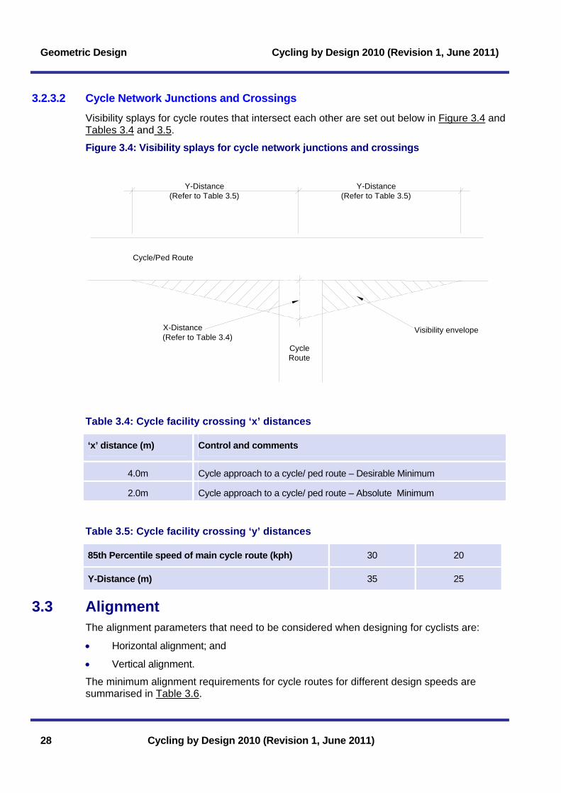
3.2.3.2 Cycle Network Junctions and Crossings Visibility splays for cycle routes that intersect each other are set out below in Figure 3.4 and Tables 3.4 and 3.5.
Figure 3.4: Visibility splays for cycle network junctions and crossings
Visibility envelopeX-Distance(Refer to Table 3.4)
Cycle/Ped Route
Y-Distance(Refer to Table 3.5)
Y-Distance(Refer to Table 3.5)
CycleRoute
Table 3.4: Cycle facility crossing ‘x’ distances
‘x’ distance (m) Control and comments
4.0m Cycle approach to a cycle/ ped route – Desirable Minimum
2.0m Cycle approach to a cycle/ ped route – Absolute Minimum
Table 3.5: Cycle facility crossing ‘y’ distances
85th Percentile speed of main cycle route (kph) 30 20
Y-Distance (m) 35 25
3.3 Alignment The alignment parameters that need to be considered when designing for cyclists are:
• Horizontal alignment; and
• Vertical alignment.
The minimum alignment requirements for cycle routes for different design speeds are summarised in Table 3.6.
28 Cycling by Design 2010 (Revision 1, June 2011)

Cycling by Design 2010 (Revision 1, June 2011) Geometric Design
Cycling by Design 2010 (Revision 1, June 2011) 29
Table 3.6: Alignment parameters
Network hierarchy
Design parameter Long distance/ commuter
Local access
Design Speed (kph) 30 20
Desirable Minimum Radius (m) 25 15 Horizontal alignment
Minimum Bellmouth Radius at junctions (m)
4.0 4.0
Desirable Minimum Crest (k) 14.1 6.8
Absolute Minimum Crest (k) 5.3 1.3
Vertical alignment
Sag values are not likely to be a controlling factor at cycle speeds and are, therefore, not specified.
3.3.1 Horizontal Alignment Other than in exceptional circumstances, the horizontal radii of the road network should exceed any minimum cyclist requirements, therefore, the guidance provided in Table 3.6 relates to off-road situations.
In order to cycle comfortably, horizontal radii are required which may be negotiated without loss of speed.
At junctions where turning speeds should be low, junction radii may be designed down to an Absolute Minimum radius of 4.0m. Radii much below 4.0m make it difficult for novice cyclists to maintain balance and line.
3.3.2 Vertical Alignment Other than in exceptional circumstances, severe crest curves are unlikely to occur on cycle routes, hence achieving adequate forward visibility in the vertical direction will rarely be a controlling factor.
Desirable Minimum vertical crest curve (k) values are based on the DSD with an average cyclist eye height of 1.5m and an object height of 0.0m.
The Absolute Minimum crest curve (k) values in Table 3.6 have been developed from a combination of the SSD values presented in Table 3.1 and general comfort criteria.
Sag values for motorised vehicles are generally based on comfort criteria. The comparatively low speeds of cyclists mean that this is not likely to be a factor. Therefore, provided the cycle facility has a generally smooth profile, it is not considered necessary to specify sag values.

Geometric Design Cycling by Design 2010 (Revision 1, June 2011)
30 Cycling by Design 2010 (Revision 1, June 2011)
3.3.3 Gradients The lower the longitudinal gradient, the more attractive a cycle route will be to the vast majority of users. Table 3.7 presents maximum gradients which are considered to be appropriate for various situations. The final choice of gradient may be controlled by a combination of factors including local conditions, safety and expected level of use. Above 5%, the gradient should be designed as a ramp with regular horizontal landings (refer to 3.3.4).
Table 3.7: Gradients
Location Gradient
Desirable Maximum 3% General cycle facility
Absolute Maximum 5%
7%
Refer to 3.3.4
Refer to 3.3.4
On the immediate approach to priority junctions
Absolute Maximum 3% Over a minimum approach distance of 6m
Desirable Maximum 3% On the approach ramp to a bridge or subway
Absolute Maximum 5%
7%
Refer to 3.3.4
Combined with treatment to control speeds – refer to 3.3.4
3.3.4 Ramps Gradients over 5% should be designed as ramps.
Disability Discrimination Act: Good Practice Guide for Roads (Transport Scotland (2009)), requires that ramps have regular landings and that the steeper the ramp the shorter the distance between landings. Where practicable, the distance between landings for different ramp gradients should be as presented in Table 3.8 (table may be interpolated).
Table 3.8: Ramp landing intervals
Gradient Maximum length Maximum rise
<3% Not a ramp. Below Desirable Maximum gradient. No landings required.
3- 5% Not a ramp. Over extended distances, landings or directional breaks may be provided where practical.
5%* 10m 500mm
7%* 5m 350mm
For background refer to Disability Discrimination Act: Good Practice Guide for Roads (Transport Scotland (2009))
* For ramps (gradients > 5%) on the approach to junctions and subways, measures to control speed may be required (refer to Section 6.4)

Cycling by Design 2010 (Revision 1, June 2011) Geometric Design
Cycling by Design 2010 (Revision 1, June 2011) 31
The length of a landing should be not less than 1.5m, measured on the centreline of the ramp. Landings may also incorporate a change in direction, and for safety reasons this should be a significant change of 30 degrees or more. Where situations prove difficult to achieve these standards the procedures set out in the Disability Discrimination Act: Good Practice Guide for Roads (Transport Scotland (2009)) should be followed.
3.3.5 Crossfall and Superelevation Excessive crossfall can cause difficulties for cyclists when manoeuvring at slow speeds and during icy weather. Disabled people are also affected by excessive crossfall.
For all routes, crossfall should be no more than is necessary for adequate drainage, with a maximum of 2.5%. Where on-carriageway crossfall exceeds this, consideration should be given to the suitability of the carriageway for cyclists.
Superelevation must not be used for for cycleways or cyclepaths.
3.4 Summary Table of Geometric Design Parameters Table 3.9 summarises the geometric design parameters covered in this Chapter.
Table 3.9: Summary of geometric design parameters
Network hierarchy
Design parameter Long distance/ commuter Local access
Design Speed (kph) 30 20
Minimum Dynamic Sight Distance (DSD) (m) 65 45
Minimum Stopping Sight Distance (SSD) (m) 35 25
Desirable Minimum Radius (m) 25 15 Horizontal alignment
Minimum Bellmouth Radius at junctions (m)
4.0 4.0
Desirable Minimum Crest (k) 14.1 6.8
Absolute Minimum Crest (k) 5.3 1.3
Vertical alignment
Sag values are not likely to be a controlling factor at cycle speeds and are, therefore, not specified.
Desirable Maximum 3% 3% Gradient
Absolute Maximum* 7% 7%
Crossfall Absolute Maximum 2.5% 2.5%
* Refer to Sections 3.3.3 and 3.3.4

Geometric Design Cycling by Design 2010 (Revision 1, June 2011)
32 Cycling by Design 2010 (Revision 1, June 2011)
Page intentionally left blank

Cycling by Design 2010 (Revision 1, June 2011) Traffic Volume and Speed
4 Traffic Volume and Speed 4.1 Appropriate Carriageway Conditions ..................................... 33 4.2 Traffic Management .................................................................. 34 4.2.1 Road Closures and Turning Restrictions ...............................................34 4.2.2 One Way Streets.....................................................................................36 4.3 Traffic Calming .......................................................................... 37 4.3.1 Central Islands ........................................................................................38 4.3.2 Pinch Points ............................................................................................39 4.3.3 Chicanes..................................................................................................40 4.4 Rural Situations......................................................................... 42 4.4.1 Speed Limits............................................................................................43 4.4.2 Road Closure/ Access Restriction..........................................................43 4.4.3 Cattle Grids and Cycle Gates .................................................................45 4.4.4 Changed Priority at Junctions.................................................................45 4.4.5 Rural Pinch Points...................................................................................46
List of Tables Table 4.1: Cycle gap widths at road closures .................................................................35 Table 4.2: Cycle bypass minimum widths.......................................................................38 Table 4.3: Chicane stagger length and motor vehicle speeds .......................................41 Table 4.4: Rural speed limit approaches.........................................................................43 List of Figures Figure 4.1: Minor road closure.........................................................................................35 Figure 4.2: False one-way street.....................................................................................36 Figure 4.3: Central island with cycle bypass...................................................................38 Figure 4.4: Pinch point .....................................................................................................40 Figure 4.5: Chicane..........................................................................................................41 Figure 4.6: Restricted access ..........................................................................................44 Figure 4.7: Cycle gate......................................................................................................45
Cycling by Design 2010 (Revision 1, June 2011)

Traffic Volume and Speed Cycling by Design 2010 (Revision 1, June 2011)
Cycling by Design 2010 (Revision 1, June 2011)
Page intentionally left blank

Cycling by Design 2010 (Revision 1, June 2011) Traffic Volume and Speed
4 Traffic Volume and Speed The road system is the most comprehensive and integrated transport network available. Creating suitable and comfortable conditions for cyclists on the carriageway is a key element of encouraging cycle use, particularly in urban areas.
This chapter outlines measures to make the road environment cycle friendly without the provision of cycle-specific measures. Cycle-specific measures for links and junctions are presented in Chapters 5-7.
4.1 Appropriate Carriageway Conditions As detailed in Section 2.2.2, the suitability of a carriageway for cycle use, principally depends on:
Cycling by Design 2010 (Revision 1, June 2011) 33
• Traffic volume;
• Traffic speed; and
• HGV content.
On roads where traffic speed, volume and HGV content are all low (refer to Figure 2.2) it is generally not necessary or desirable to provide cycle specific infrastructure, however, a site-specific assessment should always be made and recorded.
Where existing carriageways are deemed to be unsuitable for cycling, the first consideration of the designer should be whether changes can be made to the volume, speed and composition of traffic to improve cycling conditions.
There are often broader safety and other benefits to be gained by controlling traffic volume and speed rather than providing cycle-specific measures, particularly where there are high levels of pedestrian, cyclist and/ or vehicle interactions.
For neighbourhood areas, the place and social functions of streets should be prominent in design. Streets with AADT flows below 3,000 vehicles and/ or 85th percentile speeds below 32kph are attractive for cycle use and should be the design target.
On congested roads, such as busy high streets, measures to manage traffic such as those outlined in Section 4.2, should be considered on an area-wide basis. 85th percentile traffic speeds of less than 32kph should be the design target, along with high quality streetscapes.
Where vehicle parking causes difficulties for cyclists and pedestrians, its removal should be considered or cycle-specific measures such as those in Chapters 5-7 may be introduced.

Traffic Volume and Speed Cycling by Design 2010 (Revision 1, June 2011)
Benefits of shared carriageway links
• The directness and coherence of cycle journeys is maximised in most circumstances;
• The visibility of cyclists, particularly at junctions is maximised;
• Conflict with pedestrians is minimised; and
• Traffic volume and speed control has wider benefits.
4.2 Traffic Management Traffic management can be a means of optimising the road network for the benefit of all road users. Of particular benefit to cyclists are measures designed to minimise traffic volumes.
As well as strategic-level policy instruments, traffic volume reduction in specific areas can be achieved by introducing physical restrictions to motor vehicle access. This section principally considers what is required to maintain cycle access through traffic management measures.
4.2.1 Road Closures and Turning Restrictions Approach
It is sometimes desirable to restrict vehicular access on certain routes, particularly in residential areas. The measures that may be considered are:
34 Cycling by Design 2010 (Revision 1, June 2011)
• Road closures;
• False one-way streets; and
• Turning movement restrictions.
In all cases, traffic management schemes should permit all cycle movements to ensure appropriate permeability and direct access is maintained.
It is important that cycle routes are coherent and do not require cyclists to dismount to cross footways and other barriers or take unnecessary detours.
There should be a presumption in favour of cyclists being made exempt from access restrictions at road closures, junctions and false one-way streets.
Design
Gaps in physical closures can be provided, the minimum widths of which are shown in Table 4.1 and typical layouts illustrated in Figures 4.1 and 4.2.

Cycling by Design 2010 (Revision 1, June 2011) Traffic Volume and Speed
Table 4.1: Cycle gap widths at road closures
Gap characteristics* Desirable Minimum gap width
Absolute Minimum gap width (clear of gullies etc)
One-way flow 1.5m 1.2m
Two-way flow <200 cycles per hour 3.0m 2.0m
Two-way flow >200 cycles per hour >3.0m** 2.5m
* Peak hour flow should be the design parameter. The widths shown should be exceeded wherever possible, particularly where turning movements are accommodated. Access for disabled people is also fundamental. ** Width should increase with the volume of cyclists.
Access control measures may also be required where the gap could attract use by motor vehicles (refer to Section 6.4). However, emergency vehicle access must be considered and consulted upon.
Cycling by Design 2010 (Revision 1, June 2011) 35
A Traffic Regulation Order (TRO) is necessary to prohibit motor vehicle access. To avoid the restrictions applying to cyclists, they must be made exempt.
Drop kerbs allowing cyclists to mount a footway on each side of a road closure can
be a cost-effective way of retro-fitting a cycle exemption. This situation will require footway re-determination. Closure or partial closure of a road may result in increased traffic flows on other roads within the local network to the detriment of the cyclist. This impact should be considered and mitigated as appropriate.
Figure 4.1: Minor road closure
1.5m Desirable Minimum1.2m Absolute Minimum
Two w
ay road
1.5m Desirable Minimum1.2m Absolute Minimum
Build-out may be provided to preventparked cars obstructing cyclists.
Various features may be used tocreate road closures:- Extended footway- Landscape planters/tree planting- Permanent and lockable bollards- Emergency gates
Diag No.955Diag No.616
Bollards

Traffic Volume and Speed Cycling by Design 2010 (Revision 1, June 2011)
Figure 4.2: False one-way street
Diag No.616Diag No.955
1.5m Desirable Minimum1.2m Absolute Minimum
Build-out may be provided toprevent gap being obstructed by
parked cars.Bollards
Bollards
4.2.2 One Way Streets Approach
One-way streets can create unnecessary barriers to cycle access. Large one-way gyratory systems in urban areas are often inappropriate and can encourage high traffic speed and volumes in areas of vulnerable user activity. One-way traffic systems often:
• Make cycle journeys longer;
• Increase the number of junctions to be negotiated; and
• Make urban areas less permeable.
There should be a presumption in favour of cyclists being made exempt from all one-way street restrictions. Where it is necessary for safety reasons to restrict cycle access on one-way gyratories, alternative signed facilities that maintain full and direct access should be put in place.
Design S
ourc
e: J
Bew
ley
For lightly trafficked one-way streets with flows of less than 1,000 AADT and 85th percentile speeds of less than 32kph (or where the street forms part of a 20mph zone) specific cycle infrastructure is not normally required other than at street entry points. If the accepted situation in an area is to permit two-way cycling on all quiet one-way streets, drivers will not normally require messages to reinforce this.
For situations where traffic flows, speeds or parking/ loading arrangements dictate that cyclists require protection from oncoming traffic, a cycle lane can be provided. Refer to Section 5.2 for contra-flow cycle lane arrangements.
For large one-way gyratories, it is recommended that off-carriageway facilities, or alternative routes that do not delay cyclists, are built into the design.
36 Cycling by Design 2010 (Revision 1, June 2011)

Cycling by Design 2010 (Revision 1, June 2011) Traffic Volume and Speed
In all situations where two-way cycling is permitted on a one-way street, it will be necessary for the ‘one-way’ TRO to include an exemption for cyclists. Signs to TSRGD Diagram No 619 will be required.
4.3 Traffic Calming The objective of traffic calming is to modify the behaviour of drivers to the needs of non-motorised users and the local environment. Minimising the speed differential between motorised traffic and non-motorised users is a key element of designing safe carriageways for cyclists. Benefits derived may include perceived and actual improvements in road accident risk, reduced severance, improved amenity and increased social activity.
Approach
Where there is a choice, Cycling by Design recommends the use of horizontal traffic calming measures. This is because of the discomfort of successive and opposite vertical forces on some disabled people caused by the variability in construction of vertical measures. Where road humps are installed these should be of the ‘sinusoidal’ type and rigorous quality control must be employed in their construction and commissioning. Any sub-standard/ non-conforming humps should be immediately rejected and re-construction ordered. If the workmanship continues to be unacceptable then the hump should be removed.
Measures to narrow a carriageway may be applied to the entire length of a road or be restricted to individual locations. The incorporation of horizontal deflections within the carriageway can help to reduce traffic speeds, discourage unsafe manoeuvres and facilitate pedestrian and cyclist crossing movements.
Carriageway narrowings at certain locations can be potentially hazardous if poorly designed. For example, some schemes can give motor vehicle drivers the impression there is more space than is the case, leading to:
• Cyclists’ carriageway space being squeezed; and
• Motorists attempting to overtake cyclists within the narrowed area.
It is imperative that horizontal deflection schemes are designed with the safety and comfort of the cyclist in mind.
The main features used are:
• Central islands;
• Pinch points; and
• Chicanes.
As well as physical obstructions, carriageways may also be narrowed using road markings with cross sectional space being re-allocated.
Cycle Bypasses
A cycle bypass should be a primary consideration where carriageway narrowing is introduced.
Cycling by Design 2010 (Revision 1, June 2011) 37

Traffic Volume and Speed Cycling by Design 2010 (Revision 1, June 2011)
Cyclists should be guided to the bypass by a cycle lane established in advance of the point of narrowing and the lane should be of a consistent width. The access and egress points of the bypass should be kept clear of parked vehicles and give safe and easy access back onto the main carriageway without cyclists giving way to the vehicular traffic flow. The minimum widths for cycle bypasses are shown in Table 4.2.
Table 4.2: Cycle bypass minimum widths
Standard Minimum width
Comments
Desirable Minimum width 1.5m Minimum required to permit passage of sweeping vehicle where bypass is at carriageway level. Care must be taken to ensure parked cars do not obstruct the access and egress points. Gullies should be safe.
Absolute Minimum width 1.2m Gullies should be safe and a hand sweeping regime put in place where the bypass is at carriageway level.
4.3.1 Central Islands Central islands or refuges in urban speed restricted areas comprise an island within the carriageway with or without a pedestrian crossing facility. Wherever space permits, a cycle bypass should be provided, as shown in Figure 4.3 to prevent the cyclist space being squeezed by adjacent motor vehicles.
Figure 4.3: Central island with cycle bypass
1.5m desirable min1.2m absolute min
Segregation kerb of min 0.5m widthto prevent vehicles encroaching oncycle lane.
Crossing pointwhere appropriate
CycleLane
1.5m desirable min1.2m absolute min
CycleLane
Clearance strip of min 0.5mwidth to discourage
encroachment on cycle lane
Verge marker postVerge marker post
38 Cycling by Design 2010 (Revision 1, June 2011)
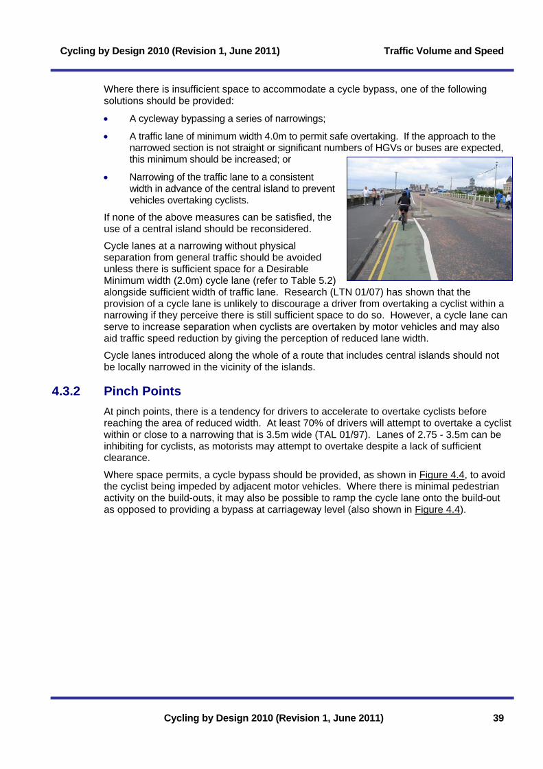
Cycling by Design 2010 (Revision 1, June 2011) Traffic Volume and Speed
Where there is insufficient space to accommodate a cycle bypass, one of the following solutions should be provided:
• A cycleway bypassing a series of narrowings;
Cycling by Design 2010 (Revision 1, June 2011) 39
• A traffic lane of minimum width 4.0m to permit safe overtaking. If the approach to the narrowed section is not straight or significant numbers of HGVs or buses are expected, this minimum should be increased; or
• Narrowing of the traffic lane to a consistent width in advance of the central island to prevent vehicles overtaking cyclists.
If none of the above measures can be satisfied, the use of a central island should be reconsidered.
Cycle lanes at a narrowing without physical separation from general traffic should be avoided unless there is sufficient space for a Desirable Minimum width (2.0m) cycle lane (refer to Table 5.2) alongside sufficient width of traffic lane. Research (LTN 01/07) has shown that the provision of a cycle lane is unlikely to discourage a driver from overtaking a cyclist within a narrowing if they perceive there is still sufficient space to do so. However, a cycle lane can serve to increase separation when cyclists are overtaken by motor vehicles and may also aid traffic speed reduction by giving the perception of reduced lane width.
Cycle lanes introduced along the whole of a route that includes central islands should not be locally narrowed in the vicinity of the islands.
4.3.2 Pinch Points At pinch points, there is a tendency for drivers to accelerate to overtake cyclists before reaching the area of reduced width. At least 70% of drivers will attempt to overtake a cyclist within or close to a narrowing that is 3.5m wide (TAL 01/97). Lanes of 2.75 - 3.5m can be inhibiting for cyclists, as motorists may attempt to overtake despite a lack of sufficient clearance.
Where space permits, a cycle bypass should be provided, as shown in Figure 4.4, to avoid the cyclist being impeded by adjacent motor vehicles. Where there is minimal pedestrian activity on the build-outs, it may also be possible to ramp the cycle lane onto the build-out as opposed to providing a bypass at carriageway level (also shown in Figure 4.4).

Traffic Volume and Speed Cycling by Design 2010 (Revision 1, June 2011)
Figure 4.4: Pinch point
3.0m
Verge marker posts
Verge marker posts
If a cycle bypass cannot be accommodated, alternatives, as indicated for central islands in Section 4.3.1, should be considered.
4.3.3 Chicanes Chicanes consist of two or more build outs on alternate sides of the carriageway permitting only one vehicle to pass at a time. They are designed to force vehicles to move firstly out of and then back in to the left side of the carriageway, and to give way to oncoming vehicles where required.
Wherever space permits, a cycle bypass should be provided at carriageway or footway level, as shown in Figure 4.5. Reference should be made to Table 4.3 to ensure the appropriate design speed.
40 Cycling by Design 2010 (Revision 1, June 2011)

Cycling by Design 2010 (Revision 1, June 2011) Traffic Volume and Speed
Figure 4.5: Chicane
W
A
Verge marker posts
Verge marker posts
Table 4.3: Chicane stagger length and motor vehicle speeds
Stagger length ‘L’ to achieve required vehicle speed in chicane (m)
Lane width ‘W’ (m)
Freeview width ‘A’ (m)
15mph 20mph 25mph
+1.0 6 9 14
0.0 9 13 18
3.0
-1.0 12 16 -
+1.0 - - 11
0.0 9 12 15
3.5
-1.0 11 15 19
+1.0 - 7 9
0.0 - 9 12
4.0
-1.0 - 11 15
Refer to (LTN 01/07) for further detail and for situations accommodating large vehicle access.
If a cycle bypass cannot be accommodated, alternatives, as indicated for central islands in Section 4.3.1 should be considered.
Cycling by Design 2010 (Revision 1, June 2011) 41

Traffic Volume and Speed Cycling by Design 2010 (Revision 1, June 2011)
4.4 Rural Situations To ensure cyclists may be safely accommodated within the rural road network, an assessment of the traffic volume and 85th percentile traffic speeds should be undertaken (refer to Section 2.2.3). This assessment should include an evaluation of the experience of cycling on the carriageway, which may conclude that no cycle-specific measures are required.
Rural roads with two-way traffic flows less than 1,000 vehicles per day should be used to form an integral part of the leisure or local access cycle network, including the National Cycle Network. Where rural roads carry between 1,000vpd and 4,000vpd, advisory cycle lanes may be considered.
Road signs and markings should be used to inform drivers they are sharing the carriageway with cyclists.
Case study: Renfrewshire’s Leisure Lanes
Renfrewshire Council has encouraged the shared use of a network of minor rural roads for both vehicles and vulnerable user groups. The scheme includes interpretive planning, with branding, signing, gateway treatment and marketing materials to inform all users of the nature of the routes.
42 Cycling by Design 2010 (Revision 1, June 2011)
Source: Renfrewshire Council
Hardstrips
Modern rural road carriageways are normally designed with 1.0m wide hardstrips. Hardstrips are not a design feature for cycling. It is recognised, however that hardstrips are used by cyclists. Where this is known to be the case, road authorities should ensure that hardstrips do not include gullies or that these are safe for cyclists and that the level of maintenance is equivalent to that of the running carriageway.

Cycling by Design 2010 (Revision 1, June 2011) Traffic Volume and Speed
4.4.1 Speed Limits The introduction of speed limits may be an effective way of increasing cycling on rural roads due to improved perceived safety. However, the speed limit imposed must be appropriate and enforceable. For example, the introduction of a 30mph speed limit on a straight, wide rural road is unlikely to be obeyed without associated carriageway measures or high levels of potentially costly enforcement. The application of speed limits may be used as shown in Table 4.4.
Table 4.4: Rural speed limit approaches
Approach * Comments
Isolated speed limit Where sections of a rural road have been assessed as being suitable for the introduction of a speed limit, a degree of traffic calming may be necessary. This approach may be suitable where a cycle track crosses the main carriageway.
Area wide Allows restrictions to be applied to a series of selected roads in order to provide a network of routes which cyclists may safely use. Within these areas, the speed limits should be enforced in conjunction with: speed limit signs, road markings (e.g. roundels)*; and traffic calming measures.
Road hierarchy Used as part of a local road hierarchy approach, where the lowest category of road may be subject to a 20mph speed limit. The road may be treated as an access only, with the resultant reduction in traffic flow and speeds making it more attractive to cyclists.
* Roundel road markings (TSRGD 1065) must be used in conjunction with the appropriate upright traffic signs. To be effective, speed limit road markings should be painted on the appropriate side of the road, however, in areas of restricted width they can be sited centrally and repeated in opposing directions.
4.4.2 Road Closure/ Access Restriction Through-traffic flows and speeds on minor rural roads may be reduced by:
• Point closure of the road by provision of a gated access point and/ or bollards at suitable locations while maintaining cycle access; or
• Restricting access by employing weight, width, vehicle category or time and season restrictions.
When proposing any road closure or restriction designers should ensure:
Sou
rce:
Cla
ckm
anna
nshi
re
Cou
ncil
• Landowners and others are consulted and are in agreement with the proposal;
• Statutory procedures are used to legally effect the measure;
• Vehicles are warned of the minor road’s status at its junction with the main road;
• Turning manoeuvre problems are not created;
Cycling by Design 2010 (Revision 1, June 2011) 43

Traffic Volume and Speed Cycling by Design 2010 (Revision 1, June 2011)
• Accessible areas of redundant carriageway are not created where fly tipping or other environmental problems result; and
• The landscape context is considered and if necessary the whole landscape setting designed to avoid the appearance of leftover space.
A typical physical closure scheme is presented in Figure 4.6.
Figure 4.6: Restricted access
Road closure or gate. Gatecan be left locked or unlocked.
Field Access
Signs and combinations of signs to be used forrestricted access to roads. Further options include:
- Weight/width restrictions- "unfit for Motor Traffic" sign- "Road Closed...Miles Ahead" sign- "Gated Road" sign
1.2m min1.5mpreferredmax.
Optionalcattle grid
Diag No. 619 Diag No. 816
Diag No. 620 Diag No. 954.4
Typical Restricted Access Plan
Typical Gated Road Closure
44 Cycling by Design 2010 (Revision 1, June 2011)

Cycling by Design 2010 (Revision 1, June 2011) Traffic Volume and Speed
4.4.3 Cattle Grids and Cycle Gates Both cattle grids and cycle gates are used regularly to prevent the passage of livestock on off-carriageway cycle tracks. Traditional cattle grids are not liked by cyclists and should be avoided if possible. Flat-topped cattle grids are preferrable to gates as they allow unobstructed passage. However, there have been instances of sheep traversing cattle grids onto adjacent carriageways (Transport Scotland (2006)). A balance has to be struck between the need of farmers to contain their sheep effectively, the need of roads authorities and the police to maintain a safe environment, and the access needs of cyclists.
Where gates are required, they should be designed as hunt-style with two-way opening, as indicated in in Figure 4.7, with a sprung or gravity closing mechanism (Transport Scotland (2006)).
Figure 4.7: Cycle gate
1570 Actual Leaf
1770 Post Centres
1395
1955
1143
SPECIFICATION50 x 50mm RHS H-FRAME50 x 25mm RHS HANG & SLAM STILESØ45mm CHS TOP & BOTTOM RAILSØ30mm CHS OTHER RAILS76 x 76mm WELD MESH
GROUNDLEVEL
GROUNDLEVEL
4.4.4 Changed Priority at Junctions Where two roads intersect, each with two-way traffic flows less than 1,000vpd, the road with the major cycle flow should, where feasible, be given priority.
Cycling by Design 2010 (Revision 1, June 2011) 45

Traffic Volume and Speed Cycling by Design 2010 (Revision 1, June 2011)
46 Cycling by Design 2010 (Revision 1, June 2011)
4.4.5 Rural Pinch Points At some locations it may be appropriate to narrow a section of road to a single track with passing places. Where such features are proposed the motorist should be given sufficient warning of their presence to comfortably modify their speed.
In areas where more modest speed restrictions are desirable, for example on sections of rural road crossed by a cycle route, the application of localised narrowing of the carriageway and optical measures may be more appropriate.
The introduction of pinch points with cycle bypasses may be used to reduce traffic speeds and act as a flow regulator on roads with high seasonal or weekend peaks in traffic flow.

Cycling by Design 2010 (Revision 1, June 2011) Allocating Carriageway Space
5 Allocating Carriageway Space 5.1 Cycle Lanes................................................................................ 47 5.1.1 Types of Cycle Lane ...............................................................................47 5.1.2 Layout......................................................................................................49 5.1.2.1 Signing and Lining................................................................................................49 5.1.2.2 Differential Coloured Surfacing............................................................................50 5.1.2.3 Road Markings to Diagram 1057 ........................................................................50 5.1.3 Cycle Lane Widths ..................................................................................51 5.1.4 Adjacent Parking and Loading ...............................................................51 5.1.5 Contra-flow Cycle Lanes.........................................................................52 5.2 Kerb-Segregated Cycle Lanes................................................. 54 5.2.1 With-Flow.................................................................................................55 5.2.2 Contra-Flow.............................................................................................55 5.2.3 Two-Way Lanes ......................................................................................55 5.3 Bus lanes.................................................................................... 56 5.3.1 With-Flow Bus Lanes..............................................................................56 5.3.2 Contra-flow Bus Lanes ...........................................................................57 5.3.3 Maintenance............................................................................................57 5.4 Cycle Lanes at Bus Stops ........................................................ 57 List of Tables Table 5.1: Features of mandatory and advisory cycle lanes..........................................48 Table 5.2: Cycle lane widths............................................................................................51 Table 5.3: Clearance strips between parking and offside cycle lane.............................52 Table 5.4: Kerb-segregated cycle lane widths................................................................54 Table 5.5: With-flow bus lane widths...............................................................................56 List of Figures Figure 5.1: Typical layout of with-flow mandatory cycle lane .........................................49 Figure 5.2: With-flow cycle lane adjacent to parking/ loading area................................52 Figure 5.3: Example of contra-flow cycle lane arrangement ..........................................53 Figure 5.4: With-flow kerb-segregated cycle lane..........................................................55 Figure 5.5: Bus layby with continuous cycle lane ...........................................................58 Figure 5.6: Cycle lane to rear of bus stop .......................................................................58 Figure 5.7: Cycle lane at bus stop boarding kerb ...........................................................58
Cycling by Design 2010 (Revision 1, June 2011)

Allocating Carriageway Space Cycling by Design 2010 (Revision 1, June 2011)
Cycling by Design 2010 (Revision 1, June 2011)
Page intentionally left blank

Cycling by Design 2010 (Revision 1, June 2011) Allocating Carriageway Space
Cycling by Design 2010 (Revision 1, June 2011) 47
5 Allocating Carriageway Space Allocating specific carriageway space for cyclists is appropriate where carriageway conditions suit and where cyclists will be advantaged by a degree of separation from vehicular traffic.
Allocating carriageway space involves the marking out of the carriageway width specifically for cyclists, or to share with other specific vehicle types. Facilities include:
• Cycle lanes;
• Kerb-segregated cycle lanes; and
• Bus lanes.
5.1 Cycle Lanes The purpose of cycle lanes is to allocate and demarcate space for cyclists within a carriageway in order to:
• Increase drivers’ awareness of cyclists;
• Encourage drivers to leave space for cyclists;
• Give people greater confidence to cycle on the road network;
• Improve perceived and actual safety;
• Assist cyclists to pass queuing traffic;
• Encourage lane discipline by cyclists and motor vehicle drivers; and
• Help to confirm a route for cyclists.
By reducing the apparent width available to general traffic, cycle lanes may, in conjunction with other measures, be used to support traffic speed reduction.
For cycle lanes to be successful it is necessary that their position on the carriageway is where cyclists want and need to be. Consideration should be given to all cyclists’ movements and whether the overall benefits of providing a cycle lane outweigh the disbenefits.
5.1.1 Types of Cycle Lane There are two basic types of cycle lane – mandatory and advisory. Table 5.1 summarises the features of each.
The purpose of a mandatory cycle lane is to define an area of the carriageway that is reserved for cyclists and which other vehicles must not encroach upon.
Advisory cycle lanes are primarily used to warn motor vehicle drivers of the presence of cyclists and to encourage them to adopt a line of travel away from cyclists. It is permissible for vehicles to drive or stop within an advisory cycle lane.
Where space permits and parking and loading can be prohibited effectively, mandatory cycle lanes should be used. Advisory cycle lanes should be considered where occasional vehicle encroachment is unavoidable.
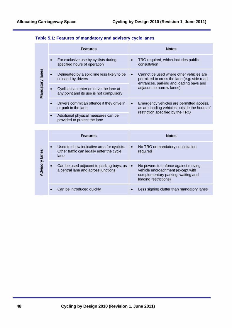
Allocating Carriageway Space Cycling by Design 2010 (Revision 1, June 2011)
48 Cycling by Design 2010 (Revision 1, June 2011)
Table 5.1: Features of mandatory and advisory cycle lanes
Features Notes
• For exclusive use by cyclists during specified hours of operation
• TRO required, which includes public consultation
• Delineated by a solid line less likely to be crossed by drivers
• Cyclists can enter or leave the lane at any point and its use is not compulsory
• Cannot be used where other vehicles are permitted to cross the lane (e.g. side road entrances, parking and loading bays and adjacent to narrow lanes)
• Drivers commit an offence if they drive in or park in the lane
Man
dato
ry la
nes
• Additional physical measures can be provided to protect the lane
• Emergency vehicles are permitted access, as are loading vehicles outside the hours of restriction specified by the TRO
Features Notes
• Used to show indicative area for cyclists. Other traffic can legally enter the cycle lane
• No TRO or mandatory consultation required
• Can be used adjacent to parking bays, as a central lane and across junctions
• No powers to enforce against moving vehicle encroachment (except with complementary parking, waiting and loading restrictions)
Adv
isor
y la
nes
• Can be introduced quickly • Less signing clutter than mandatory lanes
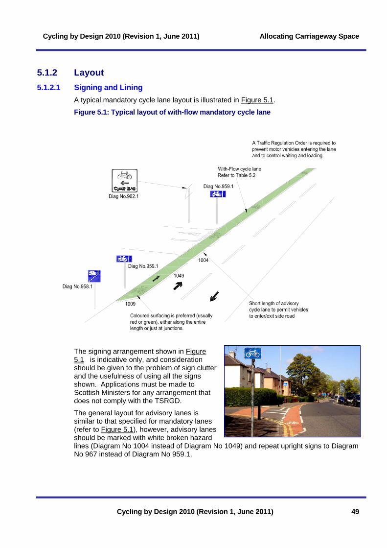
Cycling by Design 2010 (Revision 1, June 2011) Allocating Carriageway Space
5.1.2 Layout 5.1.2.1 Signing and Lining
A typical mandatory cycle lane layout is illustrated in Figure 5.1.
Figure 5.1: Typical layout of with-flow mandatory cycle lane
The signing arrangement shown in Figure 5.11 is indicative only, and consideration should be given to the problem of sign clutter and the usefulness of using all the signs shown. Applications must be made to Scottish Ministers for any arrangement that does not comply with the TSRGD.
The general layout for advisory lanes is similar to that specified for mandatory lanes (refer to Figure 5.1), however, advisory lanes should be marked with white broken hazard lines (Diagram No 1004 instead of Diagram No 1049) and repeat upright signs to Diagram No 967 instead of Diagram No 959.1.
Cycling by Design 2010 (Revision 1, June 2011) 49

Allocating Carriageway Space Cycling by Design 2010 (Revision 1, June 2011)
50 Cycling by Design 2010 (Revision 1, June 2011)
5.1.2.
etail.
5.1.2.
2 Differential Coloured Surfacing Differential coloured surfacing, typically green or red, is particularly effective across side road junctions, adjacent to parking and loading bays and queuing traffic. It may be applied over the entire length of a cycle lane, intermittently orjust at junctions. Reference should be made to TA81/99 for further d
3 Road Markings to Diagram 1057 Cycle symbol markings (TSRGD Diagram No 1057) may be used at the start of both mandatory and advisory lanes and repeated at intervals along its length provided the appropriate upright signing is also in place. It can be located across side road junctions to give added prominence to the cycle lane, and rotated to face approaching side road traffic.
Design example: advisory cycle lanes in a narrow carriageway
The replacement of a two lane single carriageway with a single, wide two-way general purpose traffic lane with advisory cycle lanes has been successfully implemented by several local authorities. East Renfrewshire Council applied this technique on a rural carriageway (Eaglesham Moor Road) carrying 1,000 vehicles per day where there was concern regarding high vehicle speeds.
The design gives the appearance of a narrow carriageway and encourages drivers to reduce speed and give appropriate space to cyclists when overtaking. Motor vehicle drivers typically give cyclists sufficient space when overtaking and encroach into the cycle lanes when passing oncoming vehicles. This technique has been used in a wide variety of both urban and rural situations.
Clackmannanshire Council has applied a similar technique while retaining the centreline (photo left).

Cycling by Design 2010 (Revision 1, June 2011) Allocating Carriageway Space
5.1.3 Cycle Lane Widths With-flow cycle lanes, whether mandatory or advisory, should be provided in accordance with the lane widths shown in Table 5.2.
Table 5.2: Cycle lane widths
Standard Width (m) Comments
Maximum Width 2.5* Lanes of this width should be used where cycle flows are expected to be >150 cycles/ peak hour and therefore cycles overtaking within the lane can be expected.
Desirable Minimum Width 2.0* The minimum width that should be considered for a cycle lane
with width for cyclists to pass each other.
Absolute Minimum Width 1.5** The running width of the lane should be free from obstructions
such as debris and unsafe gullies.
* Cycle lanes over 2.0m wide in areas of car parking may attract drivers to park in them. Physical barriers, mandatory lane markings or parking and loading restrictions can prevent this. ** Lane widths narrower than 1.5m can present a hazard to cyclists and motor vehicle drivers. Only in exceptional circumstances should widths down to 1.0m be considered where it is safe to do so – for example where stationary traffic blocks the route to an advance stop line and the proposed lane is safe from obstructions such as gullies.
Sub-standard width or poorly located cycle lanes can provide a false sense of security for both cyclists and motor vehicle drivers and encourage poor lane discipline from both. In many cases, a narrow cycle lane can encourage close proximity overtaking by motor vehicles (Parkin, J and Meyers, C (2009)). Limited space alone is not a reason for providing sub-standard width cycle lanes. Alternative solutions should be sought at such locations.
5.1.4 Adjacent Parking and Loading Where on-street parking or waiting/ loading areas require to be retained, the positioning of the cycle lane should be considered carefully. Two options are typically available:
Sou
rce:
Cyc
ling
Sco
tland
• An advisory lane on the offside of the parking/
loading bay, preferably with a clearance strip; or
• An alternative cycleway.
A typical layout of an offside cycle lane is illustrated in Figure 5.2. It is preferable that a clearance strip be provided, the width of which should be consistent with the guidance in Table 5.3.
Where double-parking occurs, the effectiveness of an offside cycle lane may be minimal without active enforcement. In such circumstances a cycleway would be more effective.
Cycling by Design 2010 (Revision 1, June 2011) 51

Allocating Carriageway Space Cycling by Design 2010 (Revision 1, June 2011)
Table 5.3: Clearance strips between parking and offside cycle lane
Standard Width (m) Comments
Desirable Minimum 1.0* Ensures that a cyclist does not need to deviate if a car door is opened
fully.
Absolute Minimum 0.5
Will require a cyclist to deviate within the cycle lane if a car door is opened. The cycle lane width in this case should be at least 1.5m, otherwise the cyclist will need to leave the cycle lane to avoid collision.
* Where required, a clearance strip of 1.5m will permit access for disabled people, without affecting cyclists using an adjacent lane.
Figure 5.2: With-flow cycle lane adjacent to parking/ loading area
Diag. 1040.4 hatching.1 in 10 taper
Refer to Table 5.2
Diag 1024(1600 high)
Diag.1004
Diag. 1057 at regular intervalsover length of parking bays
Colouredsurfacing
Parking bays
Parking bays
Refer to Table 5.3
Footway
Footway
Note – For gaps of less than 30m between parking bays, the cycle lane should not be returned to the kerbside.
To prevent motor vehicle encroachment outside of the parking bay area at the tapered hatched ends, consideration should be given to the need for a physical obstruction such as a kerbed area, or double yellow lines to prevent cyclists being impeded.
5.1.5 Contra-flow Cycle Lanes The default position should be to permit two-way cycling on one-way streets. Where there are safety concerns, the introduction of a contra-flow cycle lane may be required, as illustrated in Figure 5.3. It will be necessary for the one-way street TRO to include an exemption for cyclists.
Because of the potential risk from opposing vehicular traffic the contra-flow lane should be mandatory except across side road junctions. Kerb segregation may be provided at each end of the lane and at intermediate locations if encroachment by vehicles is likely, although street clutter should be minimised. Full kerb segregation may also be considered (Section 5.2).
52 Cycling by Design 2010 (Revision 1, June 2011)

Cycling by Design 2010 (Revision 1, June 2011) Allocating Carriageway Space
Figure 5.3: Example of contra-flow cycle lane arrangement
Note 1 - Plates exempting cyclists (Diagram No 954.4) should not be used with a ‘No Entry’ sign (Diagram No 616). Note 2 - This layout is also permitted without the ‘double D’ islands and with signs to Diagram 619 replacing signs to Diagram No 616. Note 3 - The provision of a right-turn cycle lane from the major road may be considered where the speed limit is 30mph or less.
Cycling by Design 2010 (Revision 1, June 2011) 53

Allocating Carriageway Space Cycling by Design 2010 (Revision 1, June 2011)
5.2 Kerb-Segregated Cycle Lanes Kerb-segregated cycle lanes can be effective in minimising conflict with vehicles. They are most effective on high speed rural roads and can be provided on an existing road carriageway without the need for a TRO. Transport Scotland has constructed kerb-segregated cycle lanes on the rural all-purpose roads that run parallel to the M77 and M74.
An island of minimum width 0.5m should be provided.
Kerb-segregated cycle lanes should not normally be provided adjacent to vehicle parking or pedestrian activity. In particular, kerb segregation can be a trip hazard or barrier to access for disabled people.
The Desirable and Absolute Minimum widths for kerb segregated cycle lanes are detailed in Table 5.4.
Table 5.4: Kerb-segregated cycle lane widths
Kerb-segregated cycle lane Standard Width
(m)* Comments
Desirable Minimum Width 2.0
Typically operates satisfactorily for flows of up to 200 cycles per hour. The minimum width that should be considered to permit cyclists to pass each other. With-flow or
contra-flow lane
Absolute Minimum Width 1.5 Typically operates satisfactorily for flows of up to
100 cycles per hour.
Desirable Minimum Width 3.0
Typically operates satisfactorily for two-way flows of up to 300 cycles per hour and will permit some overtaking.
Two-way lane
Absolute Minimum Width 2.0
The minimum width that should be considered to permit cyclists travelling in opposite directions to pass each other. Operates satisfactorily for two-way flows of up to 200 cycles per hour.
* The running width of the lanes should be free from obstructions such as debris, unsafe gullies, road markings and street furniture. Consideration must be given to the need for additional clearance distances to fixed objects such as kerbs (Table 6.3). Consideration should be given to an enhanced routine maintenance regime.
54 Cycling by Design 2010 (Revision 1, June 2011)

Cycling by Design 2010 (Revision 1, June 2011) Allocating Carriageway Space
5.2.1 With-Flow A typical layout of this type of facility is shown in Figure 5.4.
Figure 5.4: With-flow kerb-segregated cycle lane
Segregation Island(0.5m minimum width)
Cyclelane
Refer to Table 5.4
Regular Gapsin Segregation.
Carriageway
Footway
2.0m (1.5m) Footway
Regular gaps in the segregation island are required to allow access. Location and design of gaps requires careful consideration.
5.2.2 Contra-Flow Contra-flow cycle lanes may be segregated from traffic using a kerb island in a similar manner to with-flow lanes, with no TRO required. Section 5.1.5 gives further detail on signing and other requirements associated with contra-flow facilities.
5.2.3 Two-Way Lanes Two-way cycle lanes can be confusing to motorists and pedestrians, however, in some instances these may overcome design issues that are otherwise difficult to resolve. The width of two-way cycle lanes should be as shown in Table 5.4
Issues to consider include:
Sou
rce:
J B
ewle
y
• Additional signs and traffic calming may be required at side roads;
• Longitudinal and transverse access for all; and
• Alerting pedestrians etc to cyclists from both directions.
Cycling by Design 2010 (Revision 1, June 2011) 55

Allocating Carriageway Space Cycling by Design 2010 (Revision 1, June 2011)
5.3 Bus lanes Nearside bus lanes (with-flow and contra-flow) should be designed for use by cyclists. It is less safe for cyclists to use an offside lane, as this involves traffic on both sides and will require the cyclist to cross the path of buses when making left turns.
Designers of bus priority schemes must consider the needs of cyclists, and include provision for them. Any proposal must be taken forward in consultation with the appropriate transport authorities, bus operators and the police. Additional training on the needs of cyclists is recommended for scheduled bus operators’ drivers.
5.3.1 With-Flow Bus Lanes The recommended widths of with-flow bus lanes are shown in Table 5.5.
The Absolute Minimum width of a bus lane is 4.0m. Bus lane widths of between 3.2m and 4.0m should be avoided as this arrangement encourages unsafe overtaking and will prevent cyclists passing stopped buses within the bus lane. Where the Absolute Minimum width cannot be met, a limiting width of between 3.0m and 3.2m should be provided to prevent overtaking in the lane itself.
Table 5.5: With-flow bus lane widths
Standard Width (m) Comments*
Optimal Width 4.6 This width allows a bus to pass a cyclist within the bus lane. A 1.5m wide advisory cycle lane may be provided within the bus lane if considered desirable.
Desirable Minimum Width 4.25
Although a bus is still able to pass a cyclist within the bus lane, safe passing width is affected and this width of lane should only be provided over short distances. A 1.2m wide advisory cycle lane may be provided within the bus lane if desirable.
Absolute Minimum Width 4.0**
An Absolute Minimum width of 4.0m allows cyclists to pass stopped buses within the bus lane but may encourage unsafe overtaking of cyclists by buses, particularly where the adjacent traffic lane has queuing traffic.
Limiting Width 3.0 – 3.2** The width of the bus lane to prevent overtaking within the lane itself. A bus will be required to straddle adjacent lanes to pass a cyclist, thereby encouraging safe overtaking.
* Refer to Reid S and Guthrie N (2004) for further information on bus/ cycle interactions. ** Lane widths of between 3.2m and 4.0m should be avoided.
56 Cycling by Design 2010 (Revision 1, June 2011)

Cycling by Design 2010 (Revision 1, June 2011) Allocating Carriageway Space
5.3.2 Contra-flow Bus Lanes Although contra-flow bus lanes can improve safety and convenience for cyclists, care should be used in their development. This is especially pertinent:
• Where the contra-flow bus lane is narrow (refer to Table 5.5) – it may be necessary for buses to leave the bus lane to pass cyclists, thus increasing the risk of a collision with opposing traffic. Intermediate segregation islands may help prevent buses from transgressing the lane boundary;
• If the lane only covers a short length (<100m) with no bus stops – buses may be required to remain behind the cyclist and the limiting width shown in Table 5.5 could be appropriate; and
• When entering or leaving the contra-flow system - the cyclist is likely to be making manoeuvres that contradict other traffic. Consideration should, therefore, be given towards signals, advanced stop lines and bypasses. Pedestrian and access needs must be carefully considered
5.3.3 Maintenance Bus lanes and bus routes generally, can be subject to rapid surface deterioration. Damage to the surface discomforts and poses a safety risk to cyclists, causing them to swerve or to adopt a more central position in the road or lane lane than would otherwise be the case. Bus routes and shared bus/ cycle lanes should be prioritised for regular inspection and maintenance.
5.4 Cycle Lanes at Bus Stops Designers should always seek to minimise both delays to cyclists and conflict with bus vehicles and passengers.
Cycle lanes cannot be taken through a marked bus stop area and should be discontinued over the length of such markings.
However, where there is sufficient space, arrangements such as those illustrated in the examples in Figures 5.5, 5.6 and 5.7 may be considered.
Cycling by Design 2010 (Revision 1, June 2011) 57

Allocating Carriageway Space Cycling by Design 2010 (Revision 1, June 2011)
Figure 5.5: Bus layby with continuous cycle lane
Nominal footprint ofbus shelter 4.0m x 1.05m.
Mandatorycycle lane
Advisorycycle lane
Mandatorycycle lane
Back offootway Nominal 12m
Bus Layby
Figure 5.6: Cycle lane to rear of bus stop
Nominal footprint ofbus shelter 4.0m x 1.05m
2m desirable min(1.5m absolute min)
Kerb-faceinlet gullies
Refer toTable 5.2
Footway
Tactile Paving& Drop kerbs
Tactile Paving& Drop kerbs
Mandatorycycle lane
Mandatory cycle lane
Figure 5.7: Cycle lane at bus stop boarding kerb
Back of footway
Refer toTable 5.2
Access kerb & transitionsNominal 7.6m
Nominal footprint ofbus shelter 4.0m x 1.05m.
ramp1.8m
ramp1.8m
Mandatorycycle lane
Mandatorycycle lane
0.5m
ramp3.6m
ramp3.6m
0.5m
Kerb faceinlet gullies
58 Cycling by Design 2010 (Revision 1, June 2011)

Cycling by Design 2010 (Revision 1, June 2011) Off-Carriageway Facilities
6 Off-Carriageway Facilities 6.1 Principles.................................................................................... 59 6.1.1 Types of Off-Carriageway Facilities .......................................................59 6.1.2 When to Segregate Pedestrians and Cyclists .......................................60 6.1.3 Redetermination of Existing Footways and Footpaths ..........................62 6.1.4 Width Requirements ...............................................................................62 6.1.5 Additional Clearance Distances to Fixed Objects..................................63 6.2 Cycleways .................................................................................. 64 6.2.1 Segregated Cycleways ...........................................................................64 6.2.1.1 Segregation by Kerb ............................................................................................66 6.2.1.2 Segregation by Central Delineator Strip .............................................................66 6.2.1.3 Segregation by Verge ..........................................................................................66 6.2.1.4 Tactile Surfacing...................................................................................................66 6.2.2 Shared Cycleways ..................................................................................67 6.2.3 Bus Stops on Cycleways ........................................................................67 6.2.3.1 Segregated Cycleways ........................................................................................67 6.2.3.2 Shared Cycleways ...............................................................................................68 6.2.4 Adjacent Parking and Loading ...............................................................68 6.2.5 Guardrailing.............................................................................................69 6.2.6 Transitions with Carriageways................................................................69 6.3 Cyclepaths ................................................................................. 71 6.3.1 Shared Cyclepaths..................................................................................71 6.3.2 Segregated Cyclepaths ..........................................................................71 6.3.3 Cyclepath Situations ...............................................................................72 6.3.3.1 Dismantled Railway Lines....................................................................................72 6.3.3.2 Canal and Riverside Paths ..................................................................................72 6.3.3.3 Equestrian Routes and Bridleways .....................................................................74 6.3.3.4 British Standards..................................................................................................75 6.4 Vehicle Restricted and Pedestrianised Areas ....................... 75 6.4.1 Design .....................................................................................................75 6.4.2 Motor Vehicle Access .............................................................................76 6.4.3 Disabled People ......................................................................................76 6.5 Access Controls ........................................................................ 76 6.5.1 Reasons for Use .....................................................................................76 6.5.2 Design .....................................................................................................77
Cycling by Design 2010 (Revision 1, June 2011)

Off-Carriageway Facilities Cycling by Design 2010 (Revision 1, June 2011)
Cycling by Design 2010 (Revision 1, June 2011)
List of Tables Table 6.1: Cyclist and pedestrian flow density................................................................61 Table 6.2: Off-carriageway facility widths........................................................................63 Table 6.3: Additional clearance distances to fixed objects.............................................64 List of Figures Figure 6.1: Types of off-carriageway facilities.................................................................60 Figure 6.2: Indicative pedestrian flow densities ..............................................................61 Figure 6.3: Segregated cycleway....................................................................................65 Figure 6.4: Methods of segregation.................................................................................65 Figure 6.5: Tactile markings for segregated use facilities ..............................................67 Figure 6.6: Segregated cycleway at bus stop – example...............................................68 Figure 6.7: Shared cycleway at bus stop – example......................................................68 Figure 6.8: Transitions with carriageways.......................................................................70 Figure 6.9: Segregated cyclepath ...................................................................................71 Figure 6.10: Recommended canal path cross-section ...................................................73 Figure 6.11: Canal paths under bridges..........................................................................74 Figure 6.12: Cyclepath with separate bridleway .............................................................74 Figure 6.13: Typical bollard layout...................................................................................77 Figure 6.14: Typical chicane layout.................................................................................78

Cycling by Design 2010 (Revision 1, June 2011) Off-Carriageway Facilities
Cycling by Design 2010 (Revision 1, June 2011) 59
6 Off-Carriageway Facilities Off-carriageway facilities should be considered when the carriageway environment is assessed to be unsuitable for cyclists and it is not possible or desirable to improve on-carriageway conditions sufficiently (refer to Sections 2.2.1 and 2.2.2). There will be many situations where off-carriageway facilities provide positive advantages for cycle trips, and they form an important part of any cycle network.
In practice, most routes consist of a mix of on and off-carriageway sections and require the resolution of conflicts with pedestrians and other users. The most important aspect of route design is to ensure a high and consistent quality of provision, in line with the Core Design Principles. Interpretive signing can also be used to enhance the experience of the cyclist and be designed to complement the surrounding environment.
6.1 Principles Off-carriageway cycle routes are typically surfaces shared with or adjacent to pedestrians.
6.1.1 Types of Off-Carriageway Facilities Off-carriageway cycle routes consist of:
• Cycleways – The right of passage by foot and pedal cycle only where it is associated with, but not on, a road carriageway. Pedestrians and cyclists may share the space or be segregated from each other.
• Cyclepaths – The right of passage by foot and pedal cycle only where it is not associated with a road carriageway. Pedestrians and cyclists may share the space or be segregated from each other.
This Chapter sets out the design requirements for each of these facilities, which are illustrated in Figure 6.1.

Off-Carriageway Facilities Cycling by Design 2010 (Revision 1, June 2011)
Figure 6.1: Types of off-carriageway facilities
SegregatedCycleway
SegregatedCyclepath
SharedCyclepath
SharedCycleway
kerb
kerb
6.1.2 When to Segregate Pedestrians and Cyclists The potential for cyclist-pedestrian conflict is an important issue to be addressed as most off-carriageway routes for cyclists are used by pedestrians. The factors to be considered in determining whether shared use or segregated facilities are desirable include:
• Bicycle and pedestrian volumes: If volumes of both categories are high, pedestrians and cyclists are likely to impede each other when mixed. Density rather than just flow is the most useful measure of conflict by volume (see Table 6.1 and Figure 6.2). While density is a useful parameter, it is likely that local conditions, observation of on-site movement patterns and user views/ attitudes will play an important part in the decision-making process.
• The function of the area to pedestrians and cyclists: In a street with shops and services on both sides, both pedestrians and cyclists have an increased need for freedom of movement. In these situations, in pedestrianised environments for example, cyclists modify their behaviour accordingly (TAL 9/93) and there is limited need for segregation. However, on a radial route where the proportion of crossing and conflicting movements is low, and through movement is dominant, segregation may be more appropriate.
60 Cycling by Design 2010 (Revision 1, June 2011)

Cycling by Design 2010 (Revision 1, June 2011) Off-Carriageway Facilities
• Use by disabled people: Many disabled people, particularly those who are visually impaired, find shared facilities intimidating and stress the importance of segregation by levels. Visually impaired people use kerbs as the basis of the concept that ‘up means safe’. This concept also has an important role to play in training guide dogs.
• Available width: It may be impossible to provide segregated facilities in circumstances where the minimum width criteria cannot be achieved. A shared use or alternative facility therefore may have to be considered. In the case of segregated facilities, width plays a greater part in the success of the facility compared with a combined facility and the minimum recommended widths should not be reduced without careful consideration.
Table 6.1 indicates the type of arrangement that may be suitable on the basis of density of cyclist and pedestrian activity. Figure 6.2 provides a visual indication of different pedestrian flow densities. Designers should consider all relevant factors before arriving at a design solution. It is important to consult with all potential user groups during the design process, including local disabled access groups. The role of an Access Champion is mandatory in relation to Trunk Roads, as detailed in the Disability Discrimination Act: Good Practice Guide for Roads (Transport Scotland (2009)).
Table 6.1: Cyclist and pedestrian flow density
Combined density (users/hr/m)*
Recommended arrangement
< 100 Shared use is usually appropriate (cycles give way).
101 – 199 Segregation may be considered.
> 200 Segregation should be considered.
* Combined density per hour: the number of pedestrians and cyclists per hour per metre width.
Figure 6.2: Indicative pedestrian flow densities
1000 peds/hr/metre width (0.2 peds/m length/m width)
50m length
2mwidth
Based on a walking pace of 5km / hr
500 peds/hr/metre width (0.1 peds/m length/m width)
300 peds/hr/metre width (0.06 peds/m length/m width)
200 peds/hr/metre width (0.04 peds/m length/m width)
100 peds/hr/metre width (0.02 peds/m length/m width)
50m length
50m length
50m length
50m length
2mwidth
2mwidth
2mwidth
2mwidth
Cycling by Design 2010 (Revision 1, June 2011) 61

Off-Carriageway Facilities Cycling by Design 2010 (Revision 1, June 2011)
62 Cycling by Design 2010 (Revision 1, June 2011)
6.1.3 Redetermination of Existing Footways and Footpaths Footways and footpaths are often suitable for use by cyclists and these facilities may be redetermined by powers available under Section 152 of the Roads (Scotland) Act 1984.
Any proposal requires to be taken forward through the statutory process with full and detailed consultation with public and statutory consultees. This can improve the design and reduce the likelihood of objections to the conversion of pedestrian facilities.
No impression should be given that there is a general permission to cycle locally on footways/ footpaths. This may need to be reinforced by local publicity and signing.
6.1.4 Width Requirements The widths of off-carriageway cycle facilities are shown in Table 6.2.
Desirable Minimum dimensions are based upon a cycle facility of sufficient width to allow users to pass each other in free-flow conditions and without obstructions or constraints within or adjacent to the facility. Where ‘bunching’ is commonplace, for example at junctions and crossings, localised width increases may be desirable.
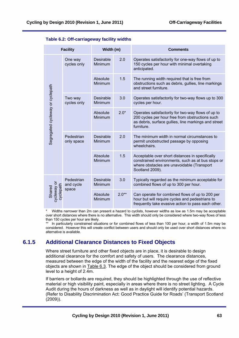
Cycling by Design 2010 (Revision 1, June 2011) Off-Carriageway Facilities
Cycling by Design 2010 (Revision 1, June 2011) 63
Table 6.2: Off-carriageway facility widths
Facility Width (m) Comments
Desirable Minimum
2.0 Operates satisfactorily for one-way flows of up to 150 cycles per hour with minimal overtaking anticipated.
One way cycles only
Absolute Minimum
1.5 The running width required that is free from obstructions such as debris, gullies, line markings and street furniture.
Desirable Minimum
3.0 Operates satisfactorily for two-way flows up to 300 cycles per hour.
Two way cycles only
Absolute Minimum
2.0* Operates satisfactorily for two-way flows of up to 200 cycles per hour free from obstructions such as debris, surface gullies, line markings and street furniture.
Desirable Minimum
2.0 The minimum width in normal circumstances to permit unobstructed passage by opposing wheelchairs. S
egre
gate
d cy
clew
ay o
r cyc
lepa
th
Pedestrian only space
Absolute Minimum
1.5 Acceptable over short distances in specifically constrained environments, such as at bus stops or where obstacles are unavoidable (Transport Scotland 2009).
Desirable Minimum
3.0 Typically regarded as the minimum acceptable for combined flows of up to 300 per hour.
Sha
red
cycl
eway
or
cycl
epat
h
Pedestrian and cycle space
Absolute Minimum
2.0** Can operate for combined flows of up to 200 per hour but will require cycles and pedestrians to frequently take evasive action to pass each other.
* Widths narrower than 2m can present a hazard to cyclists, however widths as low as 1.5m may be acceptable over short distances where there is no alternative. This width should only be considered where two-way flows of less than 150 cycles per hour are likely. ** In particularly constrained situations or for combined flows of less than 100 per hour, a width of 1.5m may be considered. However this will create conflict between users and should only be used over short distances where no alternative is available.
6.1.5 Additional Clearance Distances to Fixed Objects Where street furniture and other fixed objects are in place, it is desirable to design additional clearance for the comfort and safety of users. The clearance distances, measured between the edge of the width of the facility and the nearest edge of the fixed objects are shown in Table 6.3. The edge of the object should be considered from ground level to a height of 2.4m.
If barriers or bollards are required, they should be highlighted through the use of reflective material or high visibility paint, especially in areas where there is no street lighting. A Cycle Audit during the hours of darkness as well as in daylight will identify potential hazards. (Refer to Disability Discrimination Act: Good Practice Guide for Roads’ (Transport Scotland (2009)).

Off-Carriageway Facilities Cycling by Design 2010 (Revision 1, June 2011)
Table 6.3: Additional clearance distances to fixed objects
Object Absolute Minimum
clearance (m)
Comments
Low upstand ≤ 50 mm Nil
Kerb height 50 mm to 150mm 0.20 Added to the facility width or a separate buffer strip.
Continuous feature of height <1.2m or an isolated feature of any height (e.g. sign post, cabinet, lamp column)
0.25 Added to the facility width or a separate buffer strip. Ensure that safety fencing z-posts are capped.
Continuous feature of height >1.2m or a bridge parapet of any height
0.50 Added to the facility width or a separate buffer strip.
Carriageway 0.50* Margin (grass verge or buffer strip) between cycleway and a live carriageway.
* The Desirable Minimum clearance distance between a cycleway and carriageway with a speed limit in excess of 40mph should be 1.5m. A hardstrip can be considered to be part of the separation. Do not use grass < 1.0m width.
If a clearance distance is less than the Absolute Minimum then the effective width is narrowed and the capacity of the facility is reduced. In these situations, the Designer should consider the implications for the effectiveness of the facility (refer to Table 6.1).
The area adjacent to a cycle facility has an impact on both perceived and actual personal security. Landscaping and planting should not impede forward visibility or passive surveillance from surrounding properties, or create hiding places close to the facility. A verge or clear area, ideally not less than 1.0 metre wide, may be provided on each side of a cyclepath, with planting near the track kept below 0.8 metres high. Vegetation that is likely to grow higher should be set further back.
6.2 Cycleways Cycle facilites adjacent to the carriageway may be either segregated or shared use cycleways.
6.2.1 Segregated Cycleways Segregated cycleways usually consist of:
• Part width intended for cyclists only; and
• Part width intended for pedestrians only.
Guidance on when to segregate is provided in Section 6.1.2. This type of facility is illustrated in Figures 6.3
. This type of facility is illustrated in Figures 6.3 and 6.4.
64 Cycling by Design 2010 (Revision 1, June 2011)

Cycling by Design 2010 (Revision 1, June 2011) Off-Carriageway Facilities
Figure 6.3: Segregated cycleway
Carriageway
SegregatedCycleway(Refer toTable 6.2)
Footway
Additionalclearance
distance (Referto Table 6.3)
Figure 6.4: Methods of segregation
Max 50mmvertical kerb
SEGREGATED BY KERB
SEGREGATED BY CENTRALDELINEATOR STRIP (NOTE 2)
SEGREGATED BY VERGEPedestriansOnly
Cycles Only1.0mVerge
Cycles Only
Cycles Only
PedestriansOnly
PedestriansOnly
Note 1: Refer to Table 6.2 for cycleway widths and Table 6.3 for effective clearance widths to fixed objects. Note 2: For the design of central delineator strips, refer to the Disability Discrimination Act: Good Practice Guide for Roads (Transport Scotland (2009)). Paving setts, deterrent paving or a flush line marking (Diagram No 1049) may be considered as an alternative to a central delineator strip.
Cycling by Design 2010 (Revision 1, June 2011) 65

Off-Carriageway Facilities Cycling by Design 2010 (Revision 1, June 2011)
Segregated cycleways should be clearly signed using Diagram No. 957 with the cycle only section marked with Diagram No. 1057. Consideration should be given to the positioning of sign poles, lighting columns and other obstructions. If placement close to the facility is unavoidable, they should be made more conspicuous through the use of reflective banding and white lining for example (refer to Disability Discrimination Act: Good Practice Guide for Roads’ (Transport Scotland (2009))).
The transition from a cycleway to a footway should be clearly marked with Diagrams 1057 and 1058 where there is a risk of cyclists riding onto the pedestrian only area.
6.2.1.1 Segregation by Kerb
A cycleway may be segregated by a raised kerb, with the pedestrian space at the higher level. This is the layout that disabled people prefer.
Segregation should be continuous where the cyclist/ pedestrian positions crossover. This will discourage cyclists from continuing onto the pedestrian facility and also allow white cane users to proceed without confusion.
6.2.1.2 Segregation by Central Delineator Strip Facilities segregated by a raised white line (Diagram No 1049.1), surface texture or continuous white line (Diagram No 1049) may be provided, for example where two-way crossing movements of prams and wheelchairs are desirable.
Care should be taken to ensure that raised lines do not create ponding by providing suitable gaps in the line, for example. A 20mm profile is more effective than a 12mm at helping visually disabled people keep to the pedestrian side of the dividing line.
Colour contrasts cannot be detected by many visually impaired people. It is therefore important to ensure that the navigation requirements of this group are considered where facilities are segregated by colour contrast.
Sou
rce:
Rob
ert A
shby
6.2.1.3 Segregation by Verge A segregation verge should have a minimum width of 1.0m to discourage cross movements.
6.2.1.4 Tactile Surfacing Tactile surfaces have been developed to enable visually impaired people to position themselves on the correct side of a segregated facility (DfT (2007)).
Tactile areas should be installed at the start and end points of a segregated cycleway or cyclepath, at any junctions with other pedestrian or cyclist routes and at suitable intermediate locations. This presents visually impaired people with a ‘start’ and ‘end’ message as well as a ‘locational’ message.
Figure 6.5 illustrates a typical layout for the placement of tactile paving on segregated pedestrian and cycling facilities.
66 Cycling by Design 2010 (Revision 1, June 2011)

Cycling by Design 2010 (Revision 1, June 2011) Off-Carriageway Facilities
Figure 6.5: Tactile markings for segregated use facilities
Carriageway
2.4m
2.4m
2.4mFo
otpa
th
SegregatedCycleway
0.8m 0.8m
Shared Cyclepath
Reminder tactilearea
'Start' and 'End'tactile area
2.4m
SegregatedCyclepath
Tramline tactile Ladder tactile
6.2.2 Shared Cycleways Shared cycleways need to be designed to ensure that the quality of the environment for pedestrians and cyclists is not compromised by sharing the facility. It is important that benefits are balanced against perceived risk and inconvenience. Accessibility for disabled people will require full and detailed consideration.
Shared cycleways should be clearly signed using Diagram No 956, with Diagram No 1057 used where required.
The width of shared use cycle facilities should be in accordance with Tables 6.2 and 6.3.
6.2.3 Bus Stops on Cycleways
6.2.3.1 Segregated Cycleways
The cycling side of a segregated cycleway should generally be located between the pedestrian side and the carriageway. This assists pedestrians' perception of safety, and maximises the visibility of cyclists for drivers emerging from side roads and accesses. However, where passengers are boarding or alighting buses, this arrangement can result in conflict.
Local conditions will determine the most satisfactory arrangement. At bus stops where pedestrians are accustomed to wait at the kerb for example, it is often desirable to divert the cycle space to the rear of the area in which people are waiting. Figure 6.6 shows one way to manage conflicts. Section 5.4 shows other possible bus stop layouts.
Cycling by Design 2010 (Revision 1, June 2011) 67

Off-Carriageway Facilities Cycling by Design 2010 (Revision 1, June 2011)
Figure 6.6: Segregated cycleway at bus stop – example
Bus ShelterBus
Boarder
15.0m min 5.0m min
Ladder tactile
Tramline tactile
Diag 957Diag 957
Pedestrians
Diag 956 Diag 956Shared cycleway
Diag 1057
Surface markingto Diag 956
Surface markingto Diag 956
6.2.3.2 Shared Cycleways At bus stops on shared cycleways, there is increased potential for conflict between pedestrians and cyclists, especially where space is limited. Passengers alighting from buses are unlikely to appreciate that cyclists may be passing.
Where space is sufficent, the bus waiting area should be provided adjacent to the carriageway, with cyclists encouraged to use the rear of the area. A short length of marking may be provided to encourage this segregation of movement, as illustrated in Figure 6.7.
Figure 6.7: Shared cycleway at bus stop – example
Bus Shelter
Carriageway
Back of footway
SharedCycleway
6.2.4 Adjacent Parking and Loading Where cycleways are provided adjacent to carriageway parking and loading, the additional clearance distance to the carriageway edge applies (refer to Table 6.3).
Over long distances cycleways can take cyclists (and wheelchair users) away from their preferred line of travel and cause problems in right-turning situations. Regular breaks in parking bays should therefore be provided together with dropped kerbs/ crossings etc.
68 Cycling by Design 2010 (Revision 1, June 2011)
Cycling by Design 2010 (Revision 1, June 2011) Off-Carriageway Facilities
Cycling by Design 2010 (Revision 1, June 2011) 69
6.2.5 Guardrailing It is recommended that guardrailing is installed only where it is absolutely necessary to ensure safety or where there are requirements to direct users along a particular route. In particular:
• Guardrailing should not be located adjacent to a live carriageway where there is potential for cyclists on the carriageway to be ‘trapped’ between guardrailing and road traffic. This is particularly a problem at junctions and bends and where there is a high volume of heavy vehicles;
• Before proceeding with the installation of new guardrailing, alternative measures should be considered;
• Guardrails reduce the effective width of cycleways and cyclepaths and should not be used to segregate pedestrians and cyclists.
Full guidance on the use of guardrailing is provided in ‘Pedestrian Guardrailing’ (LTN 02/09).
When it is absolutely necessary to provide a guardrail adjacent to a cycleway, additional clearance will be required (refer to Table 6.3).
Although reduced height railings (<0.6m high) may be less intrusive, they are not recommended for segregation as they are likely to:
• Introduce the risk of pedals being caught in the railings; or
• Endanger pedestrians due to handlebars hanging over the railings and encroaching on the pedestrian space; or
• Create a trip hazard for visually impaired people.
6.2.6 Transitions with Carriageways Transitions between cycle lanes and cycleways should be safe, comfortable to use and should minimise delay to cyclists. Cyclists should not be required to negotiate tight angles unless there is a safety reason for reduced speed, and dropped kerbs should be designed flush with the carriageway.
A cycleway should not feed cyclists onto the carriageway at, or close to, road junctions, as this introduces additional conflicts at the junction. Consideration should be given to providing a cycleway transition onto the carrigeway clear of the main junction. Figure 6.8 illustrates some transition examples. A jug handle turn transition to a crossing point is illustrated in Figure 7.3.
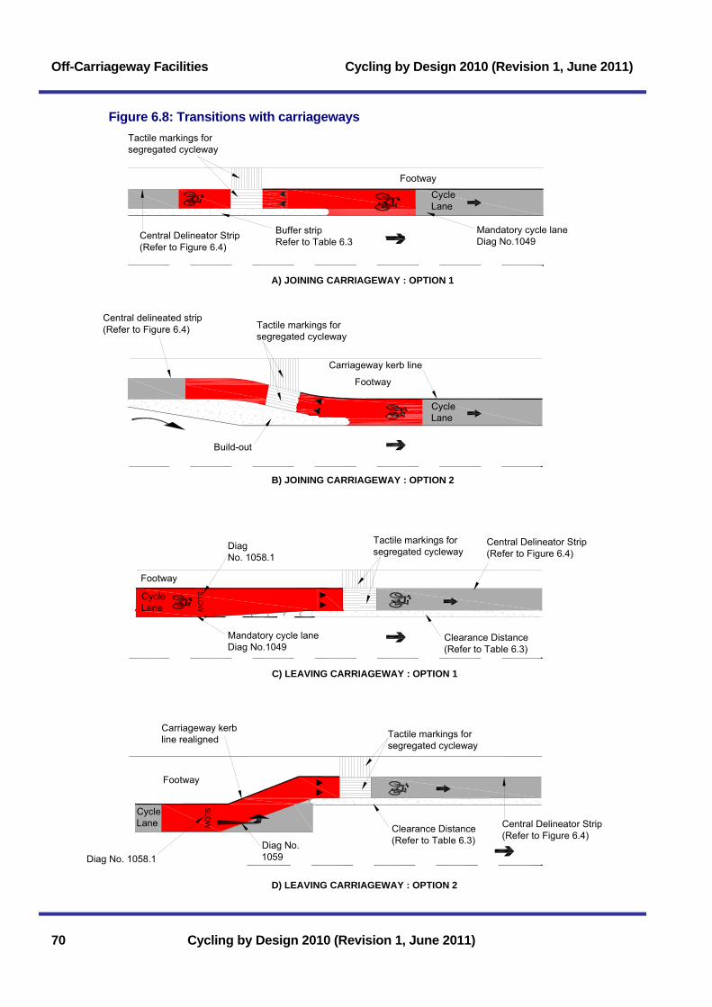
Off-Carriageway Facilities Cycling by Design 2010 (Revision 1, June 2011)
Figure 6.8: Transitions with carriageways Tactile markings forsegregated cycleway
Footway
Buffer stripRefer to Table 6.3
Mandatory cycle laneDiag No.1049
A) JOINING CARRIAGEWAY : OPTION 1
B) JOINING CARRIAGEWAY : OPTION 2
C) LEAVING CARRIAGEWAY : OPTION 1
D) LEAVING CARRIAGEWAY : OPTION 2
CycleLane
Carriageway kerb line
Build-out
Mandatory cycle laneDiag No.1049
SLO
WSLO
W
Central Delineator Strip(Refer to Figure 6.4)
Diag No.1059
Carriageway kerbline realigned
Diag No. 1058.1
DiagNo. 1058.1
Footway
CycleLane
CycleLane
Tactile markings forsegregated cycleway
Tactile markings forsegregated cycleway
Tactile markings forsegregated cycleway
Clearance Distance(Refer to Table 6.3)
CycleLane
Clearance Distance(Refer to Table 6.3)
Central Delineator Strip(Refer to Figure 6.4)
Central Delineator Strip(Refer to Figure 6.4)
Footway
Footway
Central delineated strip(Refer to Figure 6.4)
70 Cycling by Design 2010 (Revision 1, June 2011)
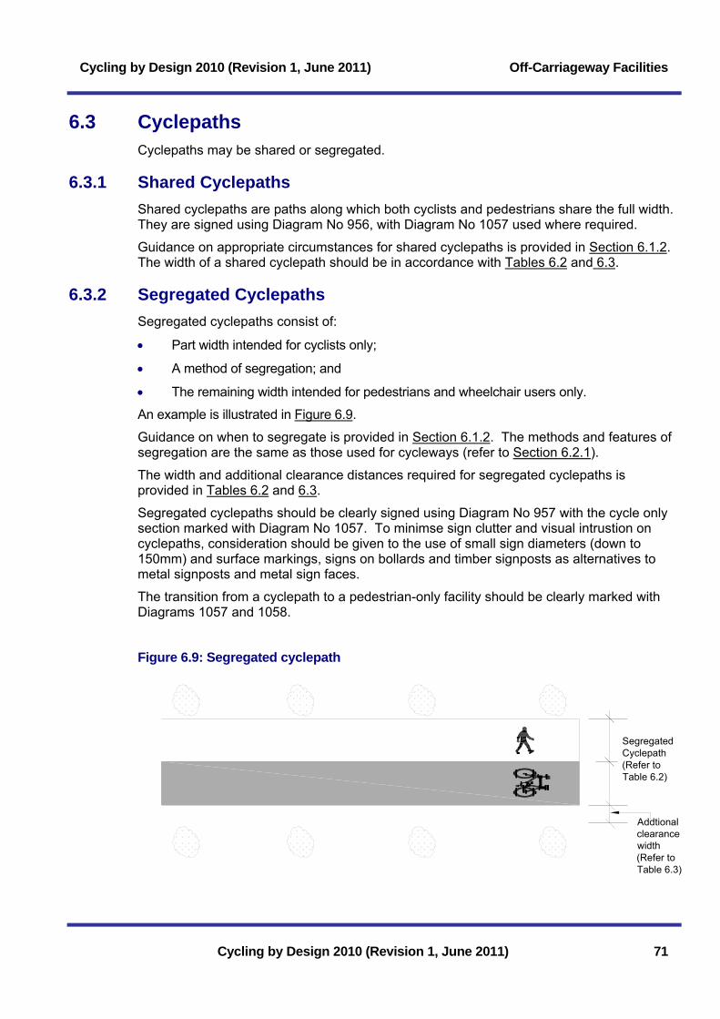
Cycling by Design 2010 (Revision 1, June 2011) Off-Carriageway Facilities
6.3 Cyclepaths Cyclepaths may be shared or segregated.
6.3.1 Shared Cyclepaths Shared cyclepaths are paths along which both cyclists and pedestrians share the full width. They are signed using Diagram No 956, with Diagram No 1057 used where required.
Guidance on appropriate circumstances for shared cyclepaths is provided in Section 6.1.2. The width of a shared cyclepath should be in accordance with Tables 6.2 and 6.3.
6.3.2 Segregated Cyclepaths Segregated cyclepaths consist of:
• Part width intended for cyclists only;
• A method of segregation; and
• The remaining width intended for pedestrians and wheelchair users only.
An example is illustrated in Figure 6.9.
Guidance on when to segregate is provided in Section 6.1.2. The methods and features of segregation are the same as those used for cycleways (refer to Section 6.2.1).
The width and additional clearance distances required for segregated cyclepaths is provided in Tables 6.2 and 6.3.
Segregated cyclepaths should be clearly signed using Diagram No 957 with the cycle only section marked with Diagram No 1057. To minimse sign clutter and visual intrustion on cyclepaths, consideration should be given to the use of small sign diameters (down to 150mm) and surface markings, signs on bollards and timber signposts as alternatives to metal signposts and metal sign faces.
The transition from a cyclepath to a pedestrian-only facility should be clearly marked with Diagrams 1057 and 1058.
Figure 6.9: Segregated cyclepath
SegregatedCyclepath(Refer toTable 6.2)
Addtionalclearancewidth(Refer toTable 6.3)
Cycling by Design 2010 (Revision 1, June 2011) 71

Off-Carriageway Facilities Cycling by Design 2010 (Revision 1, June 2011)
6.3.3 Cyclepath Situations
Paths or other facilities free from motorised traffic will either be new build or existing facilities redetermined to permit cycle use.
Redetermination should not be carried out to the detriment of existing users and can only be undertaken in accordance with statutory processes after consultation with all affected interested parties.
Potential facilities for cycle use include:
• Dismantled railway lines;
• Canal and riverside paths; and
• Bridleways.
The Roads (Scotland) Act 1984 enables the provision of a new cyclepath. Section 28 of the same act empowers the erection of barriers, raised paving, pillars, walls or fences for the purposes of safeguarding persons using the facility. The Town and Country Planning (Scotland) Act 1997 provides similar powers.
6.3.3.1 Dismantled Railway Lines
Dismantled railway lines can support safe and attractive cycling, as these have large horizontal radii and low gradients. The Designer should take account of the:
• Long term benefits of developing a dismantled railway for cycling to safeguard the permanent way for future generations;
• Planning consents required to change the use of, and make alterations to, a dismantled railway line;
• Perceptions of and actual personal security on remote routes;
• Long term resource implications due to incurred liability for structures, fence maintenance and lighting; and
• Views of Sustrans given their experience and interest in such facilities.
6.3.3.2 Canal and Riverside Paths
The conversion of canal and riverside paths provide attractive and useful cyclepaths. A number of factors should be considered:
• The available width may be less than that recommended in Table 6.2, and mitigating measures may be required as a result, including cycle speed limits, cycles give way etc;
• Sufficient width should be made available to avoid conflict with anglers. A 1.2m minimum exclusion zone adjacent to the water course is recommended (see Figure 6.10);
72 Cycling by Design 2010 (Revision 1, June 2011)
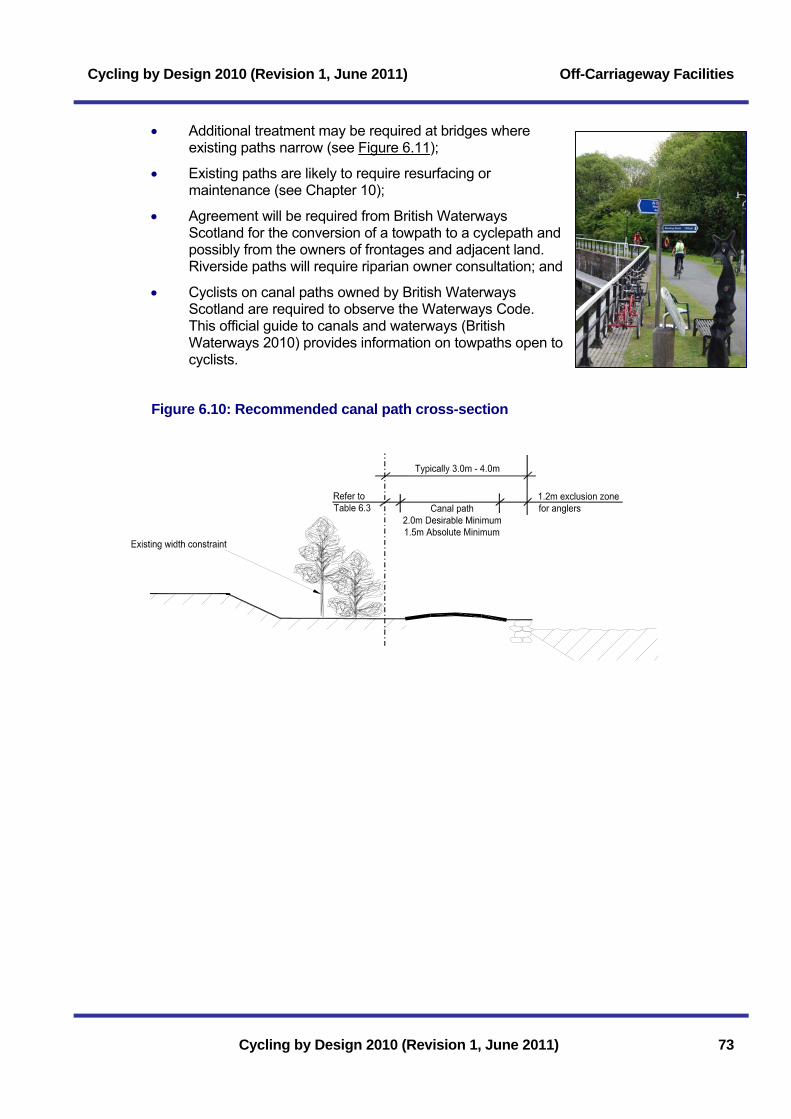
Cycling by Design 2010 (Revision 1, June 2011) Off-Carriageway Facilities
• Additional treatment may be required at bridges where existing paths narrow (see Figure 6.11);
• Existing paths are likely to require resurfacing or maintenance (see Chapter 10);
• Agreement will be required from British Waterways Scotland for the conversion of a towpath to a cyclepath and possibly from the owners of frontages and adjacent land. Riverside paths will require riparian owner consultation; and
• Cyclists on canal paths owned by British Waterways Scotland are required to observe the Waterways Code. This official guide to canals and waterways (British Waterways 2010) provides information on towpaths open to cyclists.
Figure 6.10: Recommended canal path cross-section
Cycling by Design 2010 (Revision 1, June 2011) 73
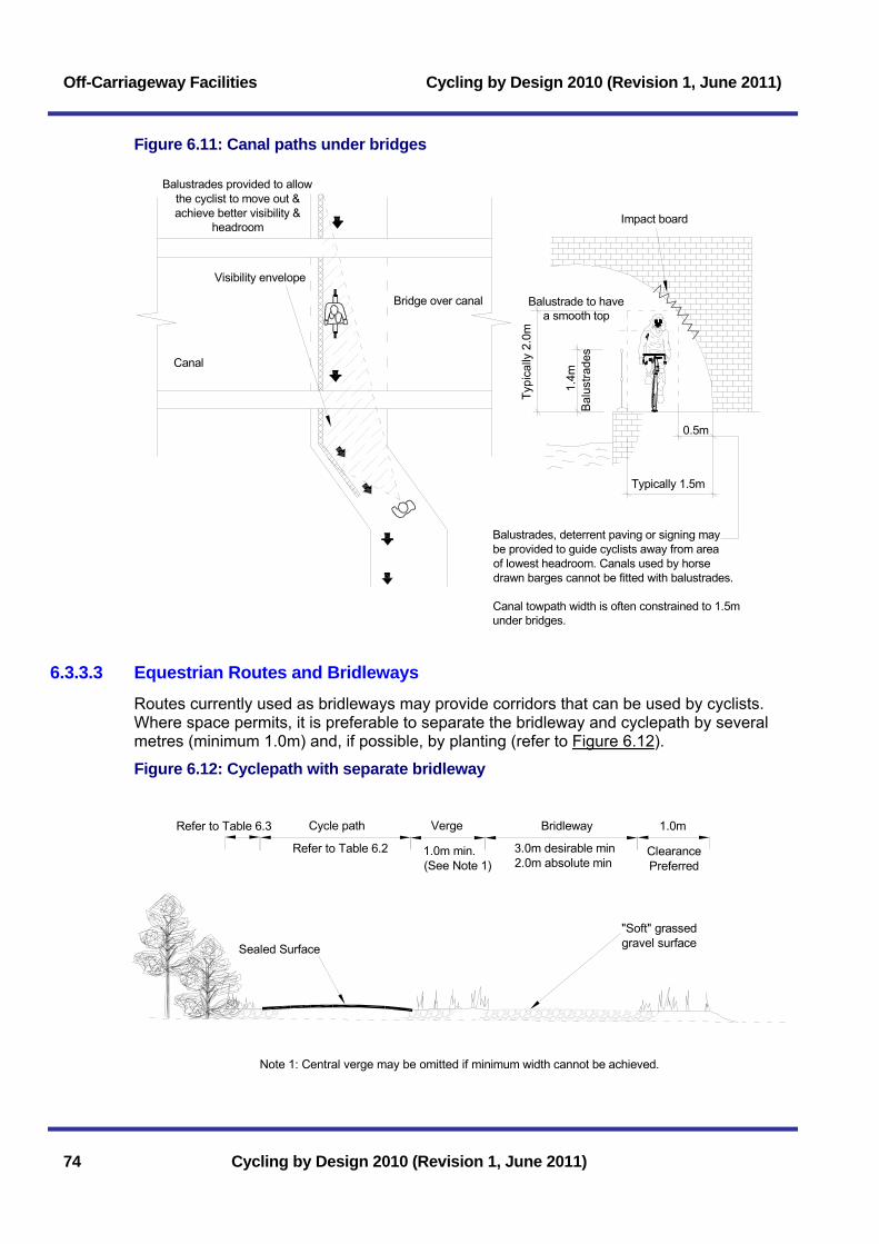
Off-Carriageway Facilities Cycling by Design 2010 (Revision 1, June 2011)
Figure 6.11: Canal paths under bridges
Balustrade to havea smooth top
0.5m
Typically 1.5m
1.4m
Bal
ustra
des
Typi
cally
2.0
m
Canal towpath width is often constrained to 1.5munder bridges.
Balustrades provided to allowthe cyclist to move out &achieve better visibility &
headroom
Visibility envelope
Bridge over canal
Balustrades, deterrent paving or signing maybe provided to guide cyclists away from areaof lowest headroom. Canals used by horsedrawn barges cannot be fitted with balustrades.
Impact board
Canal
6.3.3.3 Equestrian Routes and Bridleways Routes currently used as bridleways may provide corridors that can be used by cyclists. Where space permits, it is preferable to separate the bridleway and cyclepath by several metres (minimum 1.0m) and, if possible, by planting (refer to Figure 6.12).
Figure 6.12: Cyclepath with separate bridleway
Refer to Table 6.3 Cycle path Verge
Refer to Table 6.2 1.0m min.(See Note 1)
Bridleway 1.0m
3.0m desirable min2.0m absolute min
ClearancePreferred
"Soft" grassedgravel surfaceSealed Surface
Note 1: Central verge may be omitted if minimum width cannot be achieved.
74 Cycling by Design 2010 (Revision 1, June 2011)
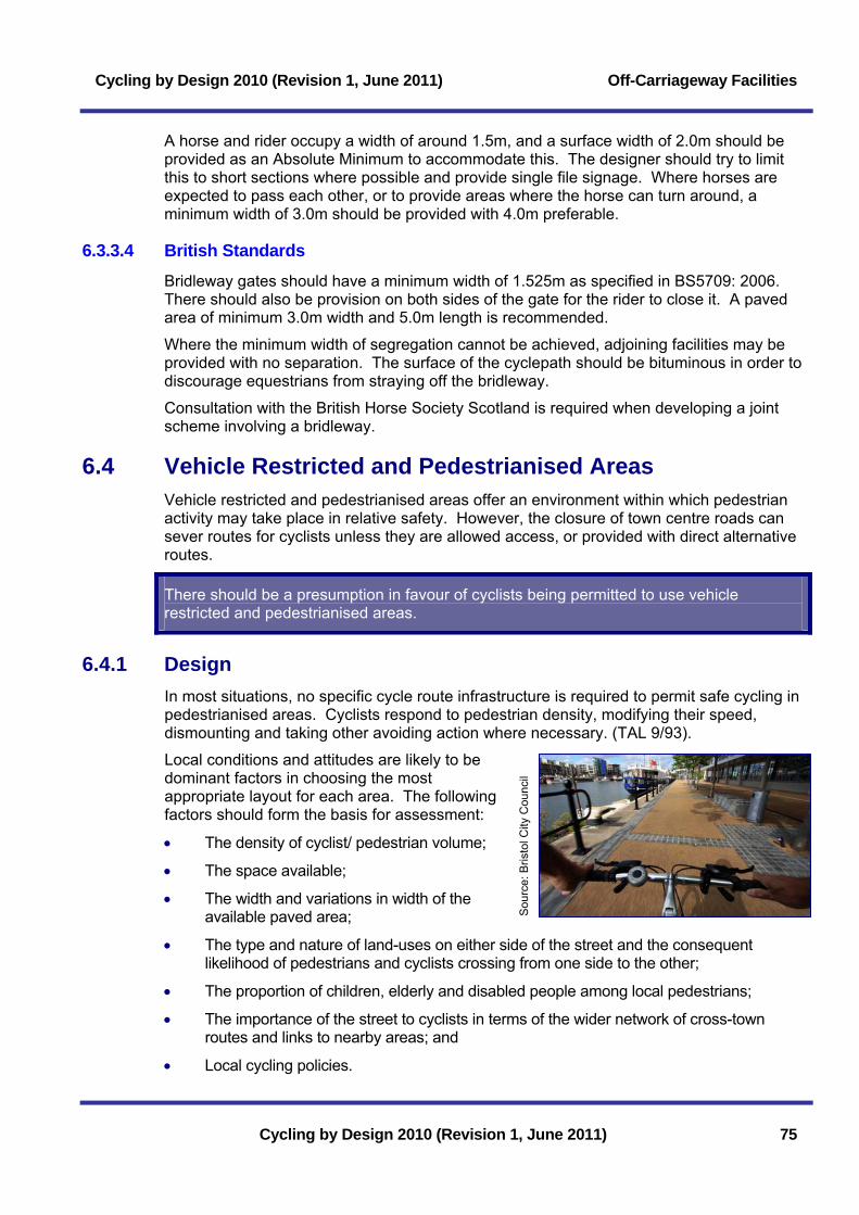
Cycling by Design 2010 (Revision 1, June 2011) Off-Carriageway Facilities
A horse and rider occupy a width of around 1.5m, and a surface width of 2.0m should be provided as an Absolute Minimum to accommodate this. The designer should try to limit this to short sections where possible and provide single file signage. Where horses are expected to pass each other, or to provide areas where the horse can turn around, a minimum width of 3.0m should be provided with 4.0m preferable.
6.3.3.4 British Standards Bridleway gates should have a minimum width of 1.525m as specified in BS5709: 2006. There should also be provision on both sides of the gate for the rider to close it. A paved area of minimum 3.0m width and 5.0m length is recommended.
Where the minimum width of segregation cannot be achieved, adjoining facilities may be provided with no separation. The surface of the cyclepath should be bituminous in order to discourage equestrians from straying off the bridleway.
Consultation with the British Horse Society Scotland is required when developing a joint scheme involving a bridleway.
6.4 Vehicle Restricted and Pedestrianised Areas Vehicle restricted and pedestrianised areas offer an environment within which pedestrian activity may take place in relative safety. However, the closure of town centre roads can sever routes for cyclists unless they are allowed access, or provided with direct alternative routes.
There should be a presumption in favour of cyclists being permitted to use vehicle restricted and pedestrianised areas.
6.4.1 Design In most situations, no specific cycle route infrastructure is required to permit safe cycling in pedestrianised areas. Cyclists respond to pedestrian density, modifying their speed, dismounting and taking other avoiding action where necessary. (TAL 9/93).
Local conditions and attitudes are likely to be dominant factors in choosing the most appropriate layout for each area. The following factors should form the basis for assessment:
Sou
rce:
Bris
tol C
ity C
ounc
il
• The density of cyclist/ pedestrian volume;
• The space available;
• The width and variations in width of the available paved area;
• The type and nature of land-uses on either side of the street and the consequent likelihood of pedestrians and cyclists crossing from one side to the other;
• The proportion of children, elderly and disabled people among local pedestrians;
• The importance of the street to cyclists in terms of the wider network of cross-town routes and links to nearby areas; and
• Local cycling policies.
Cycling by Design 2010 (Revision 1, June 2011) 75

Off-Carriageway Facilities Cycling by Design 2010 (Revision 1, June 2011)
76 Cycling by Design 2010 (Revision 1, June 2011)
Reference should be made to Section 6.1.2 for guidance. However, the density relationship is less relevant here than for linear routes and segregated solutions are unlikely to be appropriate in a pedestrianised area where direct through movements are not dominant. Where pedestrian densities and/ or cycle flows are especially high, cyclists may be advised of a particular path to take in order to assist efficient movement and reduce conflict. This may be implemented with the use of symbols designed into the streetscape, or different coloured setts. In practice, clearly marked cycle routes in a pedestrianised area can encourage high cyclist speed and may in fact be detrimental to the intended use of the area.
Cycle parking at regular intervals is required in pedestrianised areas.
6.4.2 Motor Vehicle Access In pedestrianised areas where vehicle access is required (such as loading, market or maintenance vehicles), vehicle movements should be limited to one-way only in order to minimise conflicts.
6.4.3 Disabled People Sharing space with cyclists can cause anxiety for disabled people, particularly those with visual impairments, and the design of pedestrianised areas should be carried out in consultation with all relevant access groups.
It can be desirable to define routes through pedestrianised areas which will always be free from vehicles. This can be achieved by aligning lighting columns, benches and other street furniture to create a linear strip aligned in a similar fashion to the footway in a conventional street.
6.5 Access Controls Access controls on cycle routes should be avoided wherever possible, and only used where there is a proven requirement.
6.5.1 Reasons for Use Access controls are commonly provided to prevent entry by motor vehicles, or to slow cyclists’ speed on the approach to a junction. Controls designed to exclude motorcycles are ineffective in practice and impede wheelchair users and cyclists, including users of tricycles, cycle trailers and tandems.
Existing controls should be removed or repositioned from locations where they could prevent access for wheelchair and disabled users. Close liaison with the local police is the most effective manner to deter unauthorised vehicles from cycle routes and access controls should be designed for the needs of all users.
Access control to slow cyclists or encourage young children to stop and wait for parents may be required on:
• The approach to a junction or crossing; or
• On steep ramps and gradients.
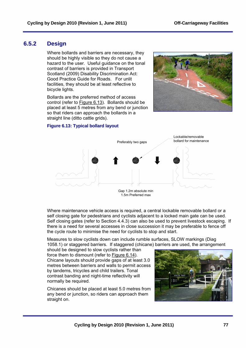
Cycling by Design 2010 (Revision 1, June 2011) Off-Carriageway Facilities
6.5.2 Design Where bollards and barriers are necessary, they should be highly visible so they do not cause a hazard to the user. Useful guidance on the tonal contrast of barriers is provided in Transport Scotland (2009) Disability Discrimination Act: Good Practice Guide for Roads. For unlit facilities, they should be at least reflective to bicycle lights.
Bollards are the preferred method of access control (refer to Figure 6.13). Bollards should be placed at least 5 metres from any bend or junction so that riders can approach the bollards in a straight line (ditto cattle grids). Figure 6.13: Typical bollard layout
Preferably two gaps
1.5m Preferred maxGap 1.2m absolute min
Lockable/removablebollard for maintenance
Where maintenance vehicle access is required, a central lockable removable bollard or a self closing gate for pedestrians and cyclists adjacent to a locked main gate can be used. Self closing gates (refer to Section 4.4.3) can also be used to prevent livestock escaping. If there is a need for several accesses in close succession it may be preferable to fence off the cycle route to minimise the need for cyclists to stop and start.
Measures to slow cyclists down can include rumble surfaces, SLOW markings (Diag 1058.1) or staggered barriers. If staggered (chicane) barriers are used, the arrangement should be designed to slow cyclists rather than force them to dismount (refer to Figure 6.14). Chicane layouts should provide gaps of at least 3.0 metres between barriers and walls to permit access by tandems, tricycles and child trailers. Tonal contrast banding and night-time reflectivity will normally be required.
Chicanes should be placed at least 5.0 metres from any bend or junction, so riders can approach them straight on.
Cycling by Design 2010 (Revision 1, June 2011) 77

Off-Carriageway Facilities Cycling by Design 2010 (Revision 1, June 2011)
Figure 6.14: Typical chicane layout
3.0m desirable min
Note: Rider meets barrier on left hand side first
2.0m desirable min1.5m absolute min
78 Cycling by Design 2010 (Revision 1, June 2011)
Cycling by Design 2010 (Revision 1, June 2011) Junctions and Crossings
7 Junctions and Crossings 7.1 Crossing Assessment .............................................................. 79 7.2 At Grade Junctions and Crossings......................................... 79 7.2.1 Simple Priority Crossings........................................................................79 7.2.1.1 Crossing with No Central Refuge (30mph or Less)............................................80 7.2.1.2 Crossing with a Central Refuge (30mph or Less) ..............................................81 7.2.1.3 Carriageway Transition and Jug Handle Turn....................................................82 7.2.1.4 Crossing of Major Road (Rural Only)..................................................................83 7.2.1.5 Crossing of an All-Purpose Dual Carriageway ...................................................83 7.2.2 Facilities at Priority Junctions .................................................................86 7.2.2.1 Cyclists on the Road Carriageway......................................................................86 7.2.2.2 Crossing of a Minor Access.................................................................................87 7.2.2.3 Crossing of a Side Road......................................................................................87 7.2.3 Signal Controlled Junctions and Crossings ...........................................90 7.2.3.1 Advanced Stop Lines (ASLs) ..............................................................................90 7.2.3.2 Cycle Bypass at a Signalised Junction ...............................................................92 7.2.3.3 Signal Controlled Crossings ................................................................................93 7.2.4 Facilities at Roundabout Junctions.........................................................94 7.2.4.1 Safety....................................................................................................................94 7.2.4.2 Layout Options .....................................................................................................95 7.2.4.3 Mini Roundabouts ................................................................................................95 7.2.4.4 Compact Roundabouts ........................................................................................96 7.2.4.5 Normal Roundabouts...........................................................................................97 7.2.4.6 Cycle Lanes at Roundabouts ..............................................................................98 7.3 Grade Separated Junctions and Crossings........................... 99 7.3.1 Facilities at Grade Separated Junctions ................................................99 7.3.2 Grade Separated Crossings...................................................................99 7.3.2.1 Subways .............................................................................................................100 7.3.2.2 Bridges................................................................................................................103
List of Tables Table 7.1: Absolute Minimum subway dimensions ......................................................101 Table 7.2: Stopping sight distances for cyclists at subways.........................................101
Cycling by Design 2010 (Revision 1, June 2011)

Junctions and Crossings Cycling by Design 2010 (Revision 1, June 2011)
Cycling by Design 2010 (Revision 1, June 2011)
List of Figures Figure 7.1: Crossing with no central refuge (30mph or less)..........................................80 Figure 7.2: Crossing with a central refuge (30mph or less)............................................81 Figure 7.3: Carriageway transition and jug handle turn..................................................82 Figure 7.4: Crossing of major road (rural only) ...............................................................84 Figure 7.5: Crossing of an all-purpose dual carriageway ...............................................85 Figure 7.6: Cycle lane on the major road of a priority junction.......................................86 Figure 7.7: Crossing of a minor access...........................................................................87 Figure 7.8: Crossing of side road (cycleway priority)......................................................88 Figure 7.9: Crossing of side road using central islands with vehicle priority..................89 Figure 7.10: Advanced stop lines ....................................................................................91 Figure 7.11: Example of cycle bypasses at a signalised junction ..................................92 Figure 7.12: Toucan crossing ..........................................................................................94 Figure 7.13: Normal and compact roundabouts .............................................................96 Figure 7.14: Subway layouts .........................................................................................102 Figure 7.15: Wheeling ramp ..........................................................................................103 Figure 7.16: Recommended bridge layout (plan) .........................................................103 Figure 7.17: Recommended bridge layout (section).....................................................104
Cycling by Design 2010 (Revision 1, June 2011) Junctions and Crossings
Cycling by Design 2010 (Revision 1, June 2011) 79
7 Junctions and Crossings Approximately 75% of reported accidents involving cyclists occur at or near a road junction (RoSPA (2009)). This chapter provides guidance on the design of junctions and crossings for cyclists, as follows:
• At grade junctions and crossings:
Simple priority crossings;
Facilities at priority junctions;
Signal controlled junctions and crossings; and
Facilities at roundabout junctions.
• Grade separated junctions and crossings:
Facilities at grade separated junctions; and
Grade separated crossings.
In designing junctions, the practitioner requires to be aware that:
• Layouts that place the cyclist within a vehicle driver’s normal field of vision are less hazardous than those that place the cyclist outwith the driver’s field of vision;
• Simple arrangements are safer than complex arrangements that require a high degree of understanding by road users; and
• Simplifying decision-making and removing ambiguity are fundamental to design.
7.1 Crossing Assessment When a cycle route crosses a road, selection of the most appropriate location and form of crossing requires careful assessment. The selection process depends on the interaction and resolution of site-specific factors, with the safety of the vulnerable road user being of paramount importance. A site-specific solution should always be sought.
7.2 At Grade Junctions and Crossings This section describes measures which can be employed where cycle facilities are on or cross a road carriageway at surface level.
For cyclists’ comfort and to make facilities accessible for cyclists of all abilities, all drop kerbs at crossings and transitions should be flush with the carriageway. Reference should be made to the Disability Discrimination Act: Good Practice Guide for Roads (Transport Scotland (2009)) for details of the design of flush kerbs and blister tactile paving for disabled people.
7.2.1 Simple Priority Crossings Priority crossings are used where cycle routes cross roads where the combination of traffic volume, speed, usage and other factors does not warrant signal control or grade separation.
Measures to accommodate cycle crossing facilties are outlined for the following situations:
• Crossing with no central refuge;
• Crossing with a central refuge;

Junctions and Crossings Cycling by Design 2010 (Revision 1, June 2011)
• Carriageway transitions and jug handle turns;
• Major rural single carriageway crossing; and
• All purpose dual carriageway crossing.
7.2.1.1 Crossing with No Central Refuge (30mph or Less) Use: In urban areas where a 30mph or lower speed limit is in place; cyclist and pedestrian flows are low; and traffic characteristics are assessed as suitable.
Design: Where the road is subject to on-street parking or visibility constraints, build-outs may be provided as shown in Figure 7.1. Care should be taken to ensure that provision of a build-out on one or both sides of the crossing does not result in a mainline carriageway that compromises the safety of cyclists or other road users. Build-outs may also be used where linear pedestrian flows are high, to enable cyclists to wait at the crossing without impeding pedestrians.
Roadside parking should be controlled to achieve the required visibility.
Figure 7.1: Crossing with no central refuge (30mph or less)
Diag No.956
Diag No.956
Build-out
Foot
way
Coloured surface preferred
Min 10m
Diag No.950Note: Distance plate DiagNo.572 may be applied.
Diag No.950
Extent of warningcontrasting colour
treatment
CyclepathCyclepath
Reflective bollards
Foot
way
Buff coloured blister tactile
80 Cycling by Design 2010 (Revision 1, June 2011)

Cycling by Design 2010 (Revision 1, June 2011) Junctions and Crossings
7.2.1.2 Crossing with a Central Refuge (30mph or Less)
Use: In urban locations where a 30mph speed limit or lower limit is in place.
Design: A typical layout for this type of crossing is provided in Figure 7.2. Care should be taken that providing a refuge island does not create a dangerous pinch point for cyclists travelling on the main carriageway (refer to Section 4.3.2).
Roadside parking should be restricted or a build-out provided where necessary to achieve the required visibility or reduce the length of crossing.
Figure 7.2: Crossing with a central refuge (30mph or less)
Note 1 - The Desirable Minimum depth of the crossing area within the central refuge is 4.0m to accommodate small groups of cyclists and allow pedestrians and cyclists to pass each other. Where the site is restricted and cyclist volume is low, the depth may be reduced to 2.5m but should be the same as the connecting path width. Note 2 - A refuge width of 3.0m minimum is desirable where it is required to accommodate tandems or cycles towing trailers.
Diag No.957
3.0m Desirable Minimum(1.8m Absolute Minimum)
Refer to Note 2
Diag No.957
Foot
way
Min 10.0m
Tapers to be provided in accordancewith Chapter 5 of the Traffic Signs Manual.
Extent of warningcontrasting colour
treatment
Absolute min 2.5m(Refer to note 1)
Diag No.610Keep left bollard
Diag No.610Keep left bollard
Segregatedcyclepath
Segregatedcyclepath
Build-out
Diag No.950
Reflective bollards
Note: Distance plate DiagNo.572 may be applied.
Diag No.950 Foot
way
Buff coloured blister tactile
Cycling by Design 2010 (Revision 1, June 2011) 81
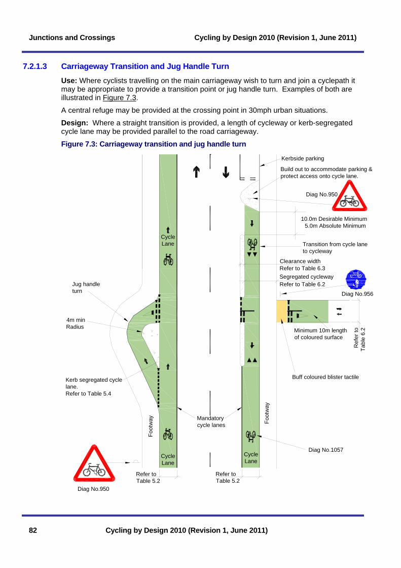
Junctions and Crossings Cycling by Design 2010 (Revision 1, June 2011)
7.2.1.3 Carriageway Transition and Jug Handle Turn
Use: Where cyclists travelling on the main carriageway wish to turn and join a cyclepath it may be appropriate to provide a transition point or jug handle turn. Examples of both are illustrated in Figure 7.3.
A central refuge may be provided at the crossing point in 30mph urban situations.
Design: Where a straight transition is provided, a length of cycleway or kerb-segregated cycle lane may be provided parallel to the road carriageway.
Figure 7.3: Carriageway transition and jug handle turn
Foot
way
Diag No.956
10.0m Desirable Minimum 5.0m Absolute Minimum
Build out to accommodate parking &protect access onto cycle lane.
Kerbside parking
Refer to Table 6.2
Refer to Table 6.3
Minimum 10m lengthof coloured surface
4m minRadius
Diag No.950
Diag No.950
Jug handleturn
CycleLane
CycleLane
CycleLane
Refer toTable 5.2
Ref
er to
Tabl
e 6.
2
Diag No.1057
Foot
way
Clearance width
Segregated cycleway
Transition from cycle laneto cycleway
Kerb segregated cyclelane.Refer to Table 5.4
Refer toTable 5.2
Mandatorycycle lanes
Buff coloured blister tactile
82 Cycling by Design 2010 (Revision 1, June 2011)
Cycling by Design 2010 (Revision 1, June 2011) Junctions and Crossings
Cycling by Design 2010 (Revision 1, June 2011) 83
7.2.1.4 Crossing of Major Road (Rural Only)
Use: On single two lane carriageway roads where the national speed limit of 60mph applies or a lower speed limit is in place, the design shown in Figure 7.4 may be provided.
If 85th percentile speeds are found to be in excess of 100kph, the Designer should implement measures to reduce vehicle speed or provide an alternative form of crossing facility.
Central refuges should not be provided for crossings of rural roads.
Design: Light-coloured high friction surfacing should be laid over the full width of the carriageway for a distance of 50m in advance of and through the crossing.
7.2.1.5 Crossing of an All-Purpose Dual Carriageway
Use: This may be used to connect two cyclepaths or cycleways where the carriageway is separated by a central reserve of suitable width and a site assessment has identified this as a suitable form of crossing.
Design: The basic design should be as illustrated in Figure 7.5. The left-right stagger ensures that users turn left to face oncoming traffic. The cycleway width in the central reserve should be maximised and a Desirable Minimum of 3.0m, with additional clearance distances to fixed objects as appropriate (Table 6.3). The depth of the crossing entry point should be the same as the cycleway/ cyclepath opposite or a minimum of 2.5m.

Junctions and Crossings Cycling by Design 2010 (Revision 1, June 2011)
Figure 7.4: Crossing of major road (rural only)
Note 1 - Chicanes or an approach stagger should be provided to slow cyclists on the approach to the crossing. This is a speed control rather than access control measure and should not force users to dismount. Reference should be made to Section 6.5 for the design of chicanes.
Diag No.956
Verge
Diag No.956
Verge
Rumble strips(15mm height, verticalface not to exceed 6mm)
High Friction Surfacing(black calcined bauxite)should only be used onroads with speed limits> 40mph
Edge of carriageway marking
Diag No.1012.1(width of line 150mm)
Diag No.950 with supplementaryplate to diagram No. 950.1
XXX ydscrossingCycles
55m
XXX ydscrossingCycles
Diag No.950 with supplementaryplate to diagram No. 950.1
XXX ydscrossingCycles
XXX ydscrossingCycles
Diag No.950 with supplementaryplate to diagram No. 950.1
Diag No.950 with supplementaryplate to diagram No. 950.1
2.5mabsoluteminimum
ChicaneRefer to Note 1
5.75m min
10m
Admiral™ or similarspecification bollards
Buff coloured blister tactile
84 Cycling by Design 2010 (Revision 1, June 2011)

Cycling by Design 2010 (Revision 1, June 2011) Junctions and Crossings
Figure 7.5: Crossing of an all-purpose dual carriageway
Diag No.956
Drop kerb at crossing pointto be flush with carriageway.
Variable width
Ver
ge
Diag No.956
10m desirable m
inimum
3.0m min
ChicaneRefer to Note 1
2.5m
abs
olut
em
in.
Min 10.0m
Extent of warningcontrasting colour
treatment
Min 5.0m
Diag No.950 with supplementary
Cycling by Design 2010 (Revision 1, June 2011) 85
asure and should not force users to dismount. Reference should be made to Section 6.5 for the design of chicanes.
Note 1 – Chicanes or an approach stagger should be provided to slow cyclists on the approach to the crossing. This is a speed control rather than access control me
plate to diagram No. 950.1
CyclescrossingXXX yds
Buff coloured blister tactile
CyclescrossingXXX yds

Junctions and Crossings Cycling by Design 2010 (Revision 1, June 2011)
7.2.2 Facilities at Priority Junctions
7.2.2.1 Cyclists on the Road Carriageway
Use: At major/ minor road junctions.
Design: Cyclists on a mainline carriageway have priority over side road entry traffic and major road turning traffic. Where a cycle lane is provided, it should be continued across the side road past the give way markings but only as an advisory cycle lane. It should be coloured and have prominent cycle symbol markings to diagram 1057 to emphasise the presence of the cycle lane. If required, cycle symbol markings can be turned 90o to face side road entry traffic.
Cycle lanes should be designed in accordance with Chapter 5 and as shown in Figure 7.6.
Figure 7.6: Cycle lane on the major road of a priority junction
It is not normally beneficial to provide cycle facilities on a minor road approach, however it may be desirable in some instances, for example where turning restrictions are in place or cyclists experience difficulty emerging from side roads, to provide cycle bypasses such as those illustrated in Figure 7.10 for signalised junctions.
A central refuge may be provided on the major road (urban areas only) to assist cyclists emerging from the side road to carry out a right turn in two stages. This may also assist cyclists in turning right into the minor road arm.
Mandatory cycle lane (Diag No.1049)
Advisory cycle lane (DiagNo.1004)M
inor
sid
e ro
ad
Diag No.602
Mandatory cycle lane (Diag No.1049)to be continued across minor roadsand accesses.
Diag No. 1057 located acrossexit to give added prominenceto the cycle lane.
Contrasting colour startsa minimum of 10m inadvance of the junctionto heighten awareness ofother road users.
Regulatory cycle lane signs have been omittedfor clarity. Refer to chapter 5 for requirements.
Tight geometry helpsreduce traffic speed
Colour contrast continued for aminimum of 8m beyond junction.
86 Cycling by Design 2010 (Revision 1, June 2011)

Cycling by Design 2010 (Revision 1, June 2011) Junctions and Crossings
7.2.2.2 Crossing of a Minor Access
Use: Where a cycleway crosses an access (either private or commercial) with low levels of vehicle movement or where it is otherwise appropriate to give priority to pedestrians and cyclists. This type of crossing is suitable for urban locations only. In rural locations, the speed of mainline road vehicles is likely to be higher, and for safety reasons priority should be given to vehicles turning into or out of the access.
Design: The layout should ensure the driver clearly understands he is crossing an area where pedestrians and cyclists have priority. The layout for a minor access crossing should be similar to that shown in Figure 7.7. Reference should be made to the Disability Discrimination Act: Good Practice Guide for Roads (Transport Scotland (2009)) for details of the ramp profiles for this type of arrangement.
The cycleway may be highlighted by providing a contrasting colour treatment on the approaches and across the access, combined with the use of cycle symbol markings (Diagram No 1057).
If the intervisibility between the cycleway and the access is below the guidelines specified in TD42/95 additional warning signs may be required.
Figure 7.7: Crossing of a minor access Carriageway
Diag No. 1057(optional)
Segregated cycleway Shared cycleway
PrivateAccess
PrivateAccess
verg
e
Sou
rce:
Rob
ert A
shby
7.2.2.3 Crossing of a Side Road Where appropriate, crossings can be configured to give cycleway users priority over the side road traffic.
Cycling by Design 2010 (Revision 1, June 2011) 87

Junctions and Crossings Cycling by Design 2010 (Revision 1, June 2011)
Cycleway priority
Use: Cycleway crossings with priority over side road traffic maintain the continuity of cycle routes, as illustrated in Figure 7.8. They can be implemented where the speed limit of both the mainline and side road is 30mph or lower in urban locations only. In rural locations for safety reasons, priority is given to the side road over the cycleway.
Figure 7.8: Crossing of side road (cycleway priority)
Note 1 - The cycle crossing should be sufficiently offset to allow for the storage of vehicles turning into the side road. Note 2 - The bendout of the cycleway should be completed prior to the crossing to allow cyclists full visibility of road traffic. Differential coloured surfacing may be provided to highlight the approach to a give way. Note 3 – The speed limit of the mainline and side roads should be 30mph or less.
Area to be keptclear for visibility.
The set back may beachieved partly by build-outs.
Refer tonote 2
Diag No.950Note: Distance plate DiagNo.572 may be applied.
Diag No.602
Restrict on-street parkingto ensure visibility
Bendout
Diag No.602
Refer to note 1
Bendout
Diag No.956
Diag No.956
Buff colouredblister tactile
88 Cycling by Design 2010 (Revision 1, June 2011)

Cycling by Design 2010 (Revision 1, June 2011) Junctions and Crossings
Design: Priority can be given to pedestrians and cyclists by providing a remote raised table as illustrated in Figure 7.8. Sufficient storage space should be provided for long vehicles to enter and exit the side road while the cycle crossing is kept close enough to the main carriageway to avoid lengthy detours and emphasise that the cycleway has priority.
Cyclist priority using transitions
Use: Cycleways may be reintroduced to the carriageway in advance of a priority junction. This provides the cyclist with unambiguous priority. Design: Cyclists pass the junction on the carriageway in a cycle lane and then rejoin the cycleway. Transitions from cycleway to cycle lane should be applied at least 30m in advance of the junction to avoid ambiguity. The layout of the cycle lane should be as illustrated in Figure 7.6. Typical transition layouts are illustrated in Figure 6.8.
Side road traffic priority
Use: Where the speed limit on the mainline carriageway or the side road is greater than 30mph or the junction is in a rural location, cycleway users should give way to vehicles at side roads for safety reasons.
Design: The layout of a side road crossing with vehicle priority is similar to those for a simple priority crossing (refer to Section 7.1). Where possible the crossing should feature a bend-out similar to that illustrated in Figure 7.8 in order to improve cycleway visibility, albeit the cyclist has to give way. An indicative layout of a side road crossing using central islands is shown in Figure 7.9. Reference should be made to TD42/95 for the geometric design of major/minor priority junctions.
Figure 7.9: Crossing of side road using central islands with vehicle priority
Note 1 – Where the site is restricted and cyclist volume is low, the absolute minimum depth may be reduced to 2.5m Note 2 – A refuge width of 3.0m is desirable where it is required to accommodate tandems or cycles towing trailers
Buff coloured blister tactile Diag No.956
3.0m desirable minimum
Diag No.956
Diag No.602
Absolute min 2.5m(Refer to note 1)
Diag No.950Note: Distance plate DiagNo.572 may be applied.
Restrict on-street parkingto ensure visibility
Bendout
Diag 610Illuminated Bollard
(Refer to note 2)
Cycling by Design 2010 (Revision 1, June 2011) 89
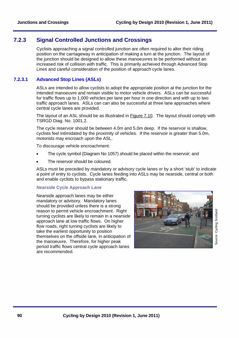
Junctions and Crossings Cycling by Design 2010 (Revision 1, June 2011)
7.2.3 Signal Controlled Junctions and Crossings Cyclists approaching a signal controlled junction are often required to alter their riding position on the carriageway in anticipation of making a turn at the junction. The layout of the junction should be designed to allow these manoeuvres to be performed without an increased risk of collision with traffic. This is primarily achieved through Advanced Stop Lines and careful consideration of the position of approach cycle lanes.
7.2.3.1 Advanced Stop Lines (ASLs) ASLs are intended to allow cyclists to adopt the appropriate position at the junction for the intended manoeuvre and remain visible to motor vehicle drivers. ASLs can be successful for traffic flows up to 1,000 vehicles per lane per hour in one direction and with up to two traffic approach lanes. ASLs can can also be successful at three lane approaches where central cycle lanes are provided.
The layout of an ASL should be as illustrated in Figure 7.10. The layout should comply with TSRGD Diag. No. 1001.2. The cycle reservoir should be between 4.0m and 5.0m deep. If the reservoir is shallow, cyclists feel intimidated by the proximity of vehicles. If the reservoir is greater than 5.0m, motorists may encroach upon the ASL. To discourage vehicle encroachment:
• The cycle symbol (Diagram No 1057) should be placed within the reservoir; and
• The reservoir should be coloured.
Sou
rce:
Cyc
ling
Sco
tland
ASLs must be preceded by mandatory or advisory cycle lanes or by a short ‘stub’ to indicate a point of entry to cyclists. Cycle lanes feeding into ASLs may be nearside, central or both and enable cyclists to bypass stationary traffic.
Nearside Cycle Approach Lane
Nearside approach lanes may be either mandatory or advisory. Mandatory lanes should be provided unless there is a strong reason to permit vehicle encroachment. Right turning cyclists are likely to remain in a nearside approach lane at low traffic flows. On higher flow roads, right turning cyclists are likely to take the earliest opportunity to position themselves on the offside lane, in anticipation of the manoeuvre. Therefore, for higher peak period traffic flows central cycle approach lanes are recommended.
90 Cycling by Design 2010 (Revision 1, June 2011)

Cycling by Design 2010 (Revision 1, June 2011) Junctions and Crossings
Figure 7.10: Advanced stop lines
Cycling by Design 2010 (Revision 1, June 2011) 91
Sou
rce:
Cyc
ling
Sco
tland
Advanced Stop Line reservoir extendsthe half width of carriageway andfacilitates right hand turn
Mandatory cycle lane
Advisory cycle lane
6.0m
5.0m7.8m 3.5m
2.8m
Cycle Reservoir:Maximum depth : 5.0mMinimum depth : 4.0m
1.5m absolute minimum(refer to table 5.2)
Central Cycle Lanes shouldnot extend further upstreamthan necessary.
3.0m1.5m
3.0m 3.0m
Central Cycle Approach Lanes
Central cycle approach lanes are recommended where there is either a high traffic flow or there is a large proportion of right turning cyclists. However, there is no single factor that indicates suitability and a site specific assessment should be carried out to facilitate an informed decision. A central cycle approach lane may be especially useful at junctions where the nearside traffic lane has been designated and is used as left-turn only.
Central cycle approach lanes should be advisory, as there will be occasions when motorists may need to encroach upon the lane in order to change position at the junction. They should not extend further upstream than necessary, to reduce the potential for conflict between cyclists and motorists. As central cycle approach lanes often place the cyclist between two rows of moving traffic the Absolute Minimum width should be 1.5m.
At some junctions, it may be beneficial to provide two or more separate cycle approach lanes for left and right turning cyclists, especially where there
are filter arrows included within the signals, but this arrangement requires approval from Scottish Ministers. Where there are filter arrows for left or right turning traffic, waiting cyclists should not be put in a position where they obstruct traffic moving off when the filter lane is active.
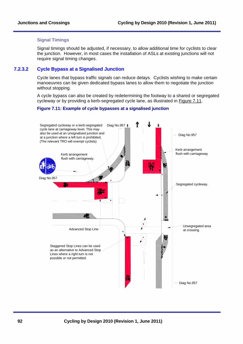
Junctions and Crossings Cycling by Design 2010 (Revision 1, June 2011)
Signal Timings
Signal timings should be adjusted, if necessary, to allow additional time for cyclists to clear the junction. However, in most cases the installation of ASLs at existing junctions will not require signal timing changes.
7.2.3.2 Cycle Bypass at a Signalised Junction Cycle lanes that bypass traffic signals can reduce delays. Cyclists wishing to make certain manoeuvres can be given dedicated bypass lanes to allow them to negotiate the junction without stopping.
A cycle bypass can also be created by redetermining the footway to a shared or segregated cycleway or by providing a kerb-segregated cycle lane, as illustrated in Figure 7.11.
Figure 7.11: Example of cycle bypasses at a signalised junction
Kerb arrangementflush with carriageway
Segregated cycleway.
Unsegregated areaat crossing.
Diag No.957
Staggered Stop Lines can be usedas an alternative to Advanced StopLines where a right turn is notpossible or not permitted.
Advanced Stop Line
Kerb arrangementflush with carriageway.
Segregated cycleway or a kerb-segregatedcycle lane at carriageway level. This mayalso be used at an unsignalised junction andat a junction where a left turn is prohibited.(The relevant TRO will exempt cyclists)
Diag No.957
Diag No.957
Diag No.957
92 Cycling by Design 2010 (Revision 1, June 2011)
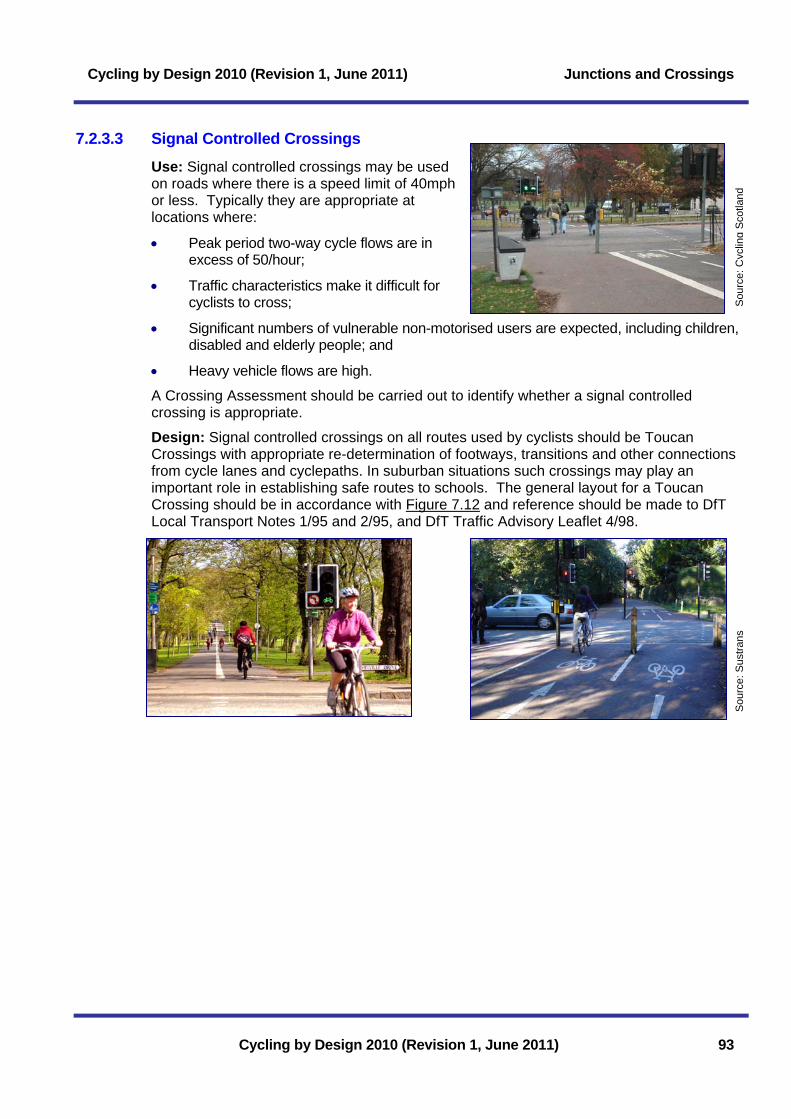
Cycling by Design 2010 (Revision 1, June 2011) Junctions and Crossings
7.2.3.3 Signal Controlled Crossings
Use: Signal controlled crossings may be used on roads where there is a speed limit of 40mph or less. Typically they are appropriate at locations where:
Sou
rce:
Cyc
ling
Sco
tland
• Peak period two-way cycle flows are in excess of 50/hour;
• Traffic characteristics make it difficult for cyclists to cross;
• Significant numbers of vulnerable non-motorised users are expected, including children, disabled and elderly people; and
• Heavy vehicle flows are high.
Cycling by Design 2010 (Revision 1, June 2011) 93
A Crossing Assessment should be carried out to identify whether a signal controlled crossing is appropriate.
Design: Signal controlled crossings on all routes used by cyclists should be Toucan Crossings with appropriate re-determination of footways, transitions and other connections from cycle lanes and cyclepaths. In suburban situations such crossings may play an important role in establishing safe routes to schools. The general layout for a Toucan Crossing should be in accordance with Figure 7.12 and reference should be made to DfT Local Transport Notes 1/95 and 2/95, and DfT Traffic Advisory Leaflet 4/98.
Sou
rce:
Sus
trans

Junctions and Crossings Cycling by Design 2010 (Revision 1, June 2011)
Figure 7.12: Toucan crossing
Diag No.956DiagNo.4002No.4003
Tactile surfacedefining segregation
DiagNo.4003
Diag No.956
Red coloured blistertactile at toucan crossing
Diag No.957
Foot
way
Sha
red
cycl
eway
10.0m MinimumExtent of warningcontrasting colour
treatment
3m absolute minimum4m desirable minimum
DiagNo.1055
300300
300
Diag No.4002DiagNo.4003
DiagNo.4002No.4003
DiagNo.4003
Foot
way
Sha
red
cycl
eway
DiagNo.1001
DiagNo.1038
SegregatedCyclepath
Clearance distance(Refer to Table 6.3)
7.2.4 Facilities at Roundabout Junctions The manner in which cyclists are accommodated at roundabouts will depend on a number of factors relating to layout and the volume and composition of traffic. Roundabouts vary in scale from simple mini roundabouts to large roundabouts catering for complex traffic patterns.
7.2.4.1 Safety
Roundabouts are the safest form of at-grade junction for general traffic, however some 10% of all reported accidents involving cyclists occur at roundabouts. Of these, 11% are likely to be either serious or fatal and more than 50% involve a motorist entering a roundabout and colliding with a cyclist using the circulatory carriageway (TAL 9/97). Cyclist accident rates at roundabouts are four times that for motor vehicle drivers.
94 Cycling by Design 2010 (Revision 1, June 2011)

Cycling by Design 2010 (Revision 1, June 2011) Junctions and Crossings
Cycling by Design 2010 (Revision 1, June 2011) 95
Cyclists will feel and be safer on roundabouts where:
• Approach arm traffic speeds are low;
• Circulatory carriageway speeds are low; and
• Cyclists are positioned prominently and are highly visible both on the approach arms and the circulatory carriageway.
These factors are a function of all geometric design parameters and of the nature of the local traffic environment. Designers should take all safety and comfort implications into consideration and should provide off-carriageway cycling facilities at roundabouts if on-carriageway running cannot be safely provided.
While this Section provides guidance for different types of roundabout, each solution must be site specific.
Where cyclists perceive carriageway conditions at a roundabout to be unsafe, they may position themselves to the kerb edge of the nearside lane of an approach arm and the outside edge of a circulatory carriageway. In this position they can be less visible to drivers and in most danger of coming into conflict with vehicles entering or leaving the roundabout.
Designers should consider how to create conditions that will allow cyclists to adopt a prominent carriageway position to ensure that they are visible to drivers. Cyclists are only likely to adopt a safe position if conditions are perceived to be safe.
Where this cannot be achieved, cyclists should be provided with an attractive off-carriageway alternative. Off-carriageway cycle facilities offer a safer route through a roundabout, however these may introduce significant additional journey times to the point that they may be unattractive to use. Off-carriageway facilities should be direct, safe and attractive to use.
The most hazardous types of roundabout for cyclists are those which are large, unsignalised, and have multiple circulation lanes. A particular problem for cyclists occurs where roundabouts are provided with segregated left turn lanes for traffic, which creates increased scope for conflict. In situations such as these, consideration should be given to the removal of such lanes or the provision of off-carriageway facilities.
7.2.4.2 Layout Options
The treatment of each type of roundabout is discussed in the following sections. Reference should be made to TD16/07 for the geometric design of roundabouts.
7.2.4.3 Mini Roundabouts
Roundabouts which have a flush, or near flush, central island of 4m diameter or less are classed as Mini Roundabouts.
Well designed Mini Roundabouts that have high levels of driver compliance with entry arm give way markings can reduce traffic approach speeds as part of traffic calming schemes and in most circumstances are suitable for on-carriageway cycling. Research has suggested that Mini Roundabouts are no less safe to cyclists than signalised junctions (TRL Report 281).
However, if the findings of a road safety audit identify a safety concern consideration may be given to providing an alternative junction layout or off-carriageway facilities for cyclists.

Junctions and Crossings Cycling by Design 2010 (Revision 1, June 2011)
7.2.4.4 Compact Roundabouts
On a cycle route the preference is for new roundabouts to be of the Compact type.
A Compact Roundabout has single lane entries and exits on each arm, which are arranged in a radial pattern, rather than tangential to the central island. The width of the circulatory carriageway is such that it is not possible for two cars to pass one another and a motorist is unlikely to attempt to pass a cyclist. Compact Roundabouts may be around 10% to 20% safer for cyclists than signalised junctions serving the same vehicle flows (TRL (2001)).
These roundabouts can accommodate flows of up to 8,000 vehicles per day (1,000 per peak hour) (Schoon and Minnen (1994)), and an individual approach arm flow of 2,500vpd.
An overrun area may be required to facilitate the movement of long vehicles, however vertical upstands and surfaces liable to skidding must be avoided.
A comparison of the layout of compact and normal roundabouts is shown in Figure 7.13.
Figure 7.13: Normal and compact roundabouts
a) COMPACT ROUNDABOUTFOR USE BY MIXED TRAFFIC
Central overrun areamay be provided
Single lane entry andexit width (4.25m)
Narrow circulatinglane width (5-7m)
Toucan crossing(staggered)
Segregated cyclewayfacility
Priority crossing
Cycle lanes
Shared cycleway
b) ROUNDABOUT WITHCYCLEWAYS
ICD range of 25m-35m
Entry and exits are perpendicularto the centre of roundabout
Central island diameterrange of 16-25mm
Minimal flares on entries
It is recommended that the cyclewayshould be two-way wherever possible.
Red colouredblister tactile
Buff coloured blister tactile
Ladder tactile
For transitions referto Figure 6.8
Ladder tactile
Tramline and ladder tactiles toindicate segregated cycleway
96 Cycling by Design 2010 (Revision 1, June 2011)

Cycling by Design 2010 (Revision 1, June 2011) Junctions and Crossings
Cycling by Design 2010 (Revision 1, June 2011) 97
7.2.4.5 Normal Roundabouts
Typically, UK roundabouts are Normal Roundabouts that have entries and exits that are flared, with two or more lanes to increase vehicle entry capacity. In urban areas, where there is a need to accommodate the movements of pedestrians and cyclists, consideration should be given to providing a Compact Roundabout or an alternative junction layout.
Traffic speeds generally increase with roundabout size. Contemporary UK design is aimed at achieving maximum entry speeds of 30mph.
In order to consider the needs of cyclists, Normal Roundabouts are sub-divided by size into three groups:
• Small Roundabouts: Inscribed Circle Diameter: 28-35m
• Medium Roundabouts: Inscribed Circle Diameter: 36-49m
• Large Roundabouts: Inscribed Circle Diameter: > 50m
Small Roundabouts:
Provided that small roundabouts are well designed and do not have excessive flares, they are unlikely to present major safety problems for cyclists.
However, where a small roundabout has wide flares on entry or limited entry path deflection higher vehicle speeds are likely. In this instance, Designers should review whether conversion of the roundabout to a Compact Roundabout is appropriate. If traffic flows are beyond the capacity of a Compact Roundabout, then separate cycleways around the outside of the roundabout may be provided.
Medium Roundabouts:
In some circumstances, cyclists may be able to use the circulatory carriageway of medium roundabouts, however this requires careful site-specific analysis of the safety of providing this layout.
Where on-carriageway conditions cannot be made suitable, the Designer may wish to consider:
• An alternative junction type;
• Conversion to a compact style roundabout, where traffic volumes are limited to below 8,000vpd; or
• Provision of off-carriageway facilities around the outside of the roundabout (refer to Figure 7.13) combined with priority or toucan signal crossing points on each arm of the roundabout. Care must be taken that signalised crossings on the exit arms are suitably offset to prevent traffic queuing back onto the roundabout.
Large Roundabouts:
Traffic speeds (particularly circulating speeds) can be significantly higher on large roundabouts and cyclists are therefore likely to be at greater risk.
While signalisation of the roundabout may assist cyclists and improve traffic operation generally, it is likely that traffic manoeuvring on and exiting the circulatory carriageway will continue to pose a safety problem for circulating cyclists.
Cyclists should therefore be offered alternative routes away from the circulatory carriageway of large roundabouts. The options available include:

Junctions and Crossings Cycling by Design 2010 (Revision 1, June 2011)
• An off-carriageway cycle facility around the outside of the roundabout (refer to Figure 7.13) with priority or signal controlled crossings of entry/ exit arms. This option is relatively inexpensive but introduces significant delay to the cyclist’s journey; or
• A grade-separated facility to enable cyclists to bypass the roundabout. This option is likely to have a high capital cost to permit all movements, but imposes minimal delay on the cyclist’s journey (see Section 7.3.2), and assists non-motorised users including disabled people generally.
Excessive visibility to the right of an approach arm can result in high entry speeds, potentially leading to accidents. On dual carriageway approaches where the speed limit is greater than 40mph, limiting visibility to the right until the final length of approach can be helpful in reducing excessive approach speeds. The screening should be at least 2.0m high, in order to block the view of all road users (refer to TD16/07).
7.2.4.6 Cycle Lanes at Roundabouts Cycle lanes on the nearside of the entry arm carriageway can position cyclists out of view of both entering and circulating vehicle drivers, and their use is not recommended.
The design of annular cycle lanes on the circulatory carriageway also requires careful consideration. Without being part of broader measures to control motor vehicle manoeuvres, they may offer little safety benefit to cyclists and may create additional hazards of their own. In particular, it is essential that when entering and circulating on a roundabout, cyclists are positioned well within the vehicle driver’s visibility envelope and that vehicle speeds and flows are not higher than cyclists can cope with.
Case study: Heworth Roundabout, York
Annular cycle lanes on roundabouts may offer no benefit or introduce extra hazards for cyclists.
However, the re-design of a priority junction in York to a roundabout with a Compact Design, with annular lanes set 1-1.5m into the roundabout, and advanced give-way lines for cyclists contributed to an 80% reduction in accidents and an increase in cycle use.
The Heworth Green Roundabout design encouraged low vehicle speeds and improvements to the visibility of cyclists. Unless leaving at the next exit, the cyclist is positioned within the visibility of drivers on approach arms.
Annular cycle lanes, should only be considered as part of a broader range of measures to reduce the circulatory carriageway to a single lane and to encourage low speeds.
Sou
rce:
City
of Y
ork
Cou
ncil
98 Cycling by Design 2010 (Revision 1, June 2011)
Cycling by Design 2010 (Revision 1, June 2011) Junctions and Crossings
Cycling by Design 2010 (Revision 1, June 2011) 99
7.3 Grade Separated Junctions and Crossings
7.3.1 Facilities at Grade Separated Junctions Grade separated junctions are commonly found on highly trafficked all-purpose trunk and principal roads. 85th percentile traffic speeds are likely to be in excess of 85kph including entry and exit speeds. Conflicts occur over the whole length of merge and diverge areas between relatively slow moving cyclists wishing to continue on the mainline and entry/ exit traffic.
Designers should include off-carriageway cycle facilities to manage these conflicts effectively. Careful consideration must be given to the design of appropriate crossings and the need for associated traffic speed reduction measures.
7.3.2 Grade Separated Crossings Use: A grade separated crossing facility should result in less delay to the cyclist and demonstrate a lower accident risk than the alternative at-grade crossing. Ideally, the cycle facility should not change level. Grade separation should be considered as a possible solution where:
• 85th percentile traffic speeds are in excess of 85kph and a crossing site assessment identifies that traffic conditions are not suitable for an at-grade crossing;
• Peak period cycle flows are likely to exceed 200 cycles per hour (recreational flow should be calculated on the basis of flows taken over a number of summer weekends); and
• Accident risk and/ or severance is considered significant.
Grade separation may not always be affordable and therefore, each individual case has to be assessed on its own merits. Designers may find that provision of speed reducing measures, combined with a signal-controlled junction, for example, may be equally appropriate.
Design: Once a decision has been made to provide grade separation, two choices are available:
• Subway – new construction or redetermination of existing; or
• Bridge – new construction or redetermination of existing.
In a number of respects subways are preferable to bridges:
• The height difference to be overcome for a subway is less than a bridge because the clearance requirement for cyclists is less than for motorised vehicles. This should result in lower and shorter approach gradients;
• Cyclists are less open to the elements in a subway;
• Subways tend to have a lesser impact on the appearance of the surroundings, thereby preserving the view of the landscape and any architectural heritage; and
• Subways generally have a lower capital cost.
However, perceived as well as actual personal security should be integral to the choice of facility to ensure it is well-used. Before a decision is made, an assessment of local

Junctions and Crossings Cycling by Design 2010 (Revision 1, June 2011)
conditions should be undertaken to confirm which type of facility will satisfy cyclists’ requirements, including consideration of the surrounding environment.
7.3.2.1 Subways Cyclists can be accomodated in new-build subways or existing pedestrian subways converted for shared use. They may be either segregated for pedestrian and cycle use or shared. When designing a socially safe cycle friendly facility, the following aims should be considered:
• Optimise through visibility from surrounding areas and intervisibility between users;
• Minimise time taken to pass through the subway; and
• Minimise the perception of enclosed space and users’ concern over personal safety.
The design of subways is detailed in TD36/93: ‘Subways for Pedestrians and Pedal Cyclists, Layout and Dimensions’. The guidance in this document and in Disability Discrimination Act: Good Practice Guide for Roads (Transport Scotland (2009)) should also be followed by designers.
Personal Security Aspects
Wide approaches, alignments with good through visibility (preferably straight), and good lighting (in keeping with surrounding lighting standards) should help to minimise users’ fears regarding personal safety. Subways and approaches should be designed to avoid possible points of concealment in the interests of personal security. Signs bearing phone numbers to report faults should be prominently displayed.
Finishes should be of a high standard, good in appearance and easy to maintain throughout the life
of the subway. Vandalism may be a major problem in urban areas. Attractiveness and good design are important factors in developing a subway which is likely to be utilised. Frequent cleaning and maintenance to preserve appearance are vital in this respect, and the additional maintenance cost should be recognised when preparing proposals.
Cross-Section
Pedestrians and cyclists can successfully share the same subway and associated ramps. For combined use to be successful, the existing and predicted desire lines should be assessed for both pedestrians and cyclists.
Whilst rectangular cross-sections are discussed within the following paragraphs, circular or other shaped sections may be used provided they circumscribe the rectangular sections with dimensions not less than the minimum recommended.
The subway dimensions shown in Table 7.1 are Absolute Minima only. The importance of perceived personal security should not be underestimated. This will often be directly related to the through visibility of a subway, a function of width, height and tapering. The Absolute
100 Cycling by Design 2010 (Revision 1, June 2011)

Cycling by Design 2010 (Revision 1, June 2011) Junctions and Crossings
Cycling by Design 2010 (Revision 1, June 2011) 101
Minima should be exceeded wherever possible to meet the needs of users, including the perception of personal security and attractiveness.
Table 7.1: Absolute Minimum subway dimensions
Type of subway Pedestrian width
Cycle width Clearance widths
Height
New subway – segregated by level, kerb or barrier
2.4m
New subway – segregated by raised white line
Refer to Table 6.2
Refer to Table 6.2
2.4m
New subway – shared use cyclepath Refer to Table 6.2
Refer to Table 6.3
2.4m
Existing subway conversion – segregated by white line
1.5m 1.5m If available 2.3m
Existing subway conversion – shared use cyclepath
2.3-3m If available 2.3m
The minimum dimensions of subway layouts are illustrated in Figure 7.14. Reference should be made to Section 6.1 for advice on the suitability of segregated and shared facilities.
Where pedestrian and cyclist flows are low (combined flows of less than 100 per hour per metre width), a shared use cyclepath may be used, particularly for short subways with good through visibility. Existing subways that are to be converted for use by cyclists may not necessarily meet the minimum widths, and consideration should be given to the need for markings and signing to alert users to the need for caution.
Stopping Sight Distances (SSD)
Recommended SSD for cyclists within the subway and on its approaches are detailed in Table 7.2. The design of subway walls, wingwalls, associated ancillary earthworks and landscape work should take account of the visibility requirements.
Table 7.2: Stopping sight distances for cyclists at subways
Design Speed (kph) Minimum SSD (m) Minimum equivalent radius of curvature of walls adjacent to cyclepath (m)
≤10 4.0 4.6
≤25 26.0 68.0
The design speed of 10kph should only be used to address safety concerns when converting existing subways for joint use by pedestrians, cyclists and disabled people.

Junctions and Crossings Cycling by Design 2010 (Revision 1, June 2011)
Figure 7.14: Subway layouts
2.3m
1.5m
Cyclists
1.5m
Pedestrians
2.4m
(2.7
m)
2.3m
(2.6
m)
Refer toTable6.3
Margin Cyclists Pedestrians
2.4m
(2.7
m)
c) Existing Subway Conversion - Typical Section
Central delineator strip
Dimensions shown on sectionare typical for urban subways. (Refer toTable 6.2 for absolute minimum width)
a) New Subway : Typical Section(Delineated by level difference)
b) New Subway : Typical Section(Shared Use)
Refer toTable
6.2
Refer toTable
6.2 Refer to Table 6.2
Access
102 Cycling by Design 2010 (Revision 1, June 2011)
Access ramps and stairways should be at least the same width as the subway. Ramp gradients should comply with the guidance provided in Sections 3.3.3 and 3.3.4.
Ramps should not be allowed to run into the subway beyond the threshold unless additional headroom is provided.
The thresholds of all subway accesses, tops and bottoms of flights of stairs, should be provided with a system of tactile paving to assist visually impaired people.
Wheeling ramps may be provided on stairways (refer to Figure 7.15) but cognisance has to be taken of handrail requirements. The Disability Discrimination Act: Good Practice Guide for Roads (Transport Scotland (2009)) should be followed as regards accessibility.

Cycling by Design 2010 (Revision 1, June 2011) Junctions and Crossings
Figure 7.15: Wheeling ramp
200mm min.
50mm wide, 30mmSteps deep channel
7.3.2.2 Bridges
To avoid environmental (visual) impact and long diversions via ramps, a bridge should only be proposed where a subway is inappropriate.
Detailed design standards are provided in ‘BD29/04: Design Criteria for Footbridges’. The guidance in this document and in Disability Discrimination Act: Good Practice Guide for Roads (Transport Scotland (2009)) should also be followed by designers.
The plan and section layouts of bridges are illustrated in Figures 7.16 and 7.17 and summarised in the following paragraphs.
Figure 7.16: Recommended bridge layout (plan)
Appropriate lead-in barriers to the bridgeparapet should be considered particularlyif the approach is on an incline.
Ramp gradient(Refer to Section 3.3.4)
Guard rail maybe appropriate
Separatestep access Speed control measures
may be required on ramps
Sou
rce:
J B
ewle
y
Cycling by Design 2010 (Revision 1, June 2011) 103

Junctions and Crossings Cycling by Design 2010 (Revision 1, June 2011)
Figure 7.17: Recommended bridge layout (section)
Facilities may be either segregated or fully shared with pedestrians. The form of segregation on the structure should be compatible with that provided on its approaches. The minimum widths for cyclepaths on the bridge and approach ramps should be in accordance with Tables 6.2 and 6.3.
A proposal to convert an existing foot or road bridge should be assessed on its own merits in consultation with all parties potentially affected. The design of the bridge and current usage should be reviewed alongside the quality of other possible routes.
Pedestrians Cycles
Central delineator strip
1.4m
FIGURE 7.17A : NEW BRIDGE SECTION
3.0m min two way2.0m min one way 0.5m Clearance where practical
(Refer to Table 6.3)
Shared cycleway
FIGURE 7.17B : EXISTING ROAD BRIDGE SECTION
Existing parapets should be retained subjectto safety audit and monitoring
Where required, consideration shouldbe given to reducing carriageway lanewidths in order to widen the cycleway.
(Refer to Table 6.2) (Refer to Table 6.2 and 6.3)
104 Cycling by Design 2010 (Revision 1, June 2011)
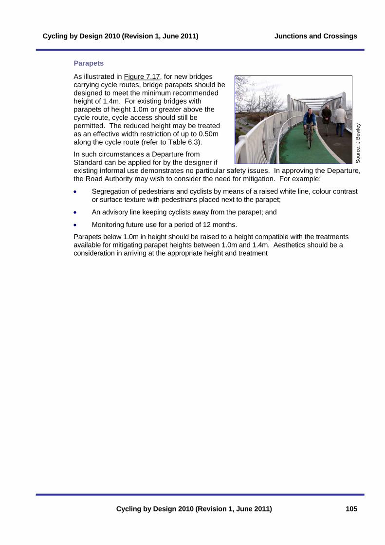
Cycling by Design 2010 (Revision 1, June 2011) Junctions and Crossings
Parapets
As illustrated in Figure 7.17, for new bridges carrying cycle routes, bridge parapets should be designed to meet the minimum recommended height of 1.4m. For existing bridges with parapets of height 1.0m or greater above the cycle route, cycle access should still be permitted. The reduced height may be treated as an effective width restriction of up to 0.50m along the cycle route (refer to Table 6.3).
In such circumstances a Departure from Standard can be applied for by the designer if existing informal use demonstrates no particular safety issues. In approving the Departure, the Road Authority may wish to consider the need for mitigation. For example:
Sou
rce:
J B
ewle
y
• Segregation of pedestrians and cyclists by means of a raised white line, colour contrast or surface texture with pedestrians placed next to the parapet;
• An advisory line keeping cyclists away from the parapet; and
• Monitoring future use for a period of 12 months.
Parapets below 1.0m in height should be raised to a height compatible with the treatments available for mitigating parapet heights between 1.0m and 1.4m. Aesthetics should be a consideration in arriving at the appropriate height and treatment
Cycling by Design 2010 (Revision 1, June 2011) 105

Junctions and Crossings Cycling by Design 2010 (Revision 1, June 2011)
106 Cycling by Design 2010 (Revision 1, June 2011)
Page intentionally left blank

Cycling by Design 2010 (Revision 1, June 2011) Cycle Parking
8 Cycle Parking 8.1 Planning for Cycle Parking .................................................... 107 8.1.1 Basic Requirements..............................................................................107 8.1.2 User Requirements ...............................................................................107 8.1.3 Demand and Capacity Requirements ..................................................108 8.2 Location and Access .............................................................. 110 8.2.1 On-Street Situations..............................................................................111 8.3 Detailed Design ....................................................................... 111 8.3.1 General Considerations ........................................................................111 8.3.2 Short to Medium Term Parking ............................................................112 8.3.2.1 Sheffield Stands .................................................................................................112 8.3.2.2 Wall Loops..........................................................................................................113 8.3.3 Medium to Long Term Parking .............................................................114 8.3.3.1 Cycle Stores .......................................................................................................114 8.3.3.2 Cycle Lockers.....................................................................................................115 8.3.3.3 Car Parks............................................................................................................115 8.3.4 Traffic Signs ..........................................................................................116
List of Tables Table 8.1: Parking design requirements by user type .................................................107 Table 8.2: Parking provision by land use .....................................................................109 List of Figures Figure 8.1: Typical Sheffield Stand ..............................................................................113 Figure 8.2: Wall loops ...................................................................................................113 Figure 8.3: Typical cycle store layout ...........................................................................114 Figure 8.4: Typical layout of a cycle locker scheme .....................................................115
Cycling by Design 2010 (Revision 1, June 2011)

Cycle Parking Cycling by Design 2010 (Revision 1, June 2011)
Cycling by Design 2010 (Revision 1, June 2011)
Page intentionally left blank

Cycling by Design 2010 (Revision 1, June 2011) Cycle Parking
8 Cycle Parking 8.1 Planning for Cycle Parking
As well as serving a functional purpose, the provision of carefully planned, well located and secure parking facilities helps promote cycle use by making bicycles a prominent part of the built environment. Well designed parking with sufficient capacity reduces the clutter of bicycles chained to railings, drainpipes and lighting columns, which can affect accessibility, especially for disabled people.
8.1.1 Basic Requirements
Sou
rce:
Cog
& W
heel
Parking facilities should be:
• Convenient, visible, accessible, convenient and easy to use;
• Safe and secure – facilities should be located in areas that are overlooked and lit;
• Fit for purpose – the type and amount of cycle parking used should serve the needs of the users and the local land use;
• Attractive – designs should be appropriate to the surrounding area and match other street furniture;
• Coherent – cycle parking should sit within the context of a cycle route network connecting main origins and destinations. Cyclists having to dismount between a cycle route and parking is a deterrent; and
• Well managed and well maintained – systems should be efficient to use, clean and free from damaged or abandoned bicycles.
8.1.2 User Requirements When planning cycle parking, careful consideration must be given to the needs of those who are using the facility. Table 8.1 details the needs of typical users.
Table 8.1: Parking design requirements by user type
User Parking period Particular requirements
School children Short, medium and long term
Appropriately sized stands, covered, in an area of surveillance (natural or otherwise), easy to use, and protected from pedestrian and vehicular traffic, within the school grounds.
Commuters/ employees
Medium term Secure (ideally a locked compound), covered, in an area of surveillance (natural or otherwise) and near entrance or within building/ grounds.
Cycling by Design 2010 (Revision 1, June 2011) 107

Cycle Parking Cycling by Design 2010 (Revision 1, June 2011)
User Parking period Particular requirements
Public transport users
Medium term Secure (ideally a locked compound), covered, in an area of surveillance (natural or otherwise) and located as part of an interchange. Toilets, fresh water and wash facilities at the main terminals for touring cyclists.
Leisure and recreation
Short, medium and long term – dependant on destination.
Provision of extra space for trailer bike and luggage lockers. Protected from pedestrian and vehicular traffic.
Residents Medium and long term Secure (ideally a locked compound), covered, in an area of surveillance (natural or otherwise) in or adjacent to buildings.
General – local services and facilities (e.g. shops; GP surgeries etc)
Short term (potentially medium as well)
At regular intervals along shop frontages, easy to use, in an area of and with additional space for easy loading.
Mobility impaired users (disabled people, families, elderly)
Short, medium and long term – dependant on destination.
Provision of adequate space for ease of movement, in an area of natural surveillance, and protected from pedestrian and vehicular traffic.
Short Term <2 hours; Medium Term 2-12 hours; and Long Term >12 hours.
8.1.3 Demand and Capacity Requirements To be successful cycle parking requires to be considered as part of the transportation aspects of development control and built into the early stages of development planning.
Table 8.2 provides recommended parking capacity for different types of land use. The capacities recommended should be considered as a guide only. This guidance is also relevant to retro-fitting parking capacity. The local situation should be considered to ensure sufficient parking is provided and that it can be extended in future. Consideration may be given to the following information sources in determining the level of cycle parking for a development (see also Chapter 2):
• Counts and Surveys – cycle surveys that have assessed the provision of and demand for cycle parking;
• Modal Split Data – provides a guide of cycling levels with an area;
• Demographic Data – consideration of the catchment population of an area;
• Latent demand – as a minimum, cycle parking provision should reflect targets for growth in cycling. These targets may be part of a Local Transport Strategy, Travel Plan or on-site assessment; and
108 Cycling by Design 2010 (Revision 1, June 2011)

Cycling by Design 2010 (Revision 1, June 2011) Cycle Parking
• Census Data – figures should always be adjusted to include any possible growth and for any journeys that may not have been captured by the Census.
Local Authorities may find it appropriate to develop their own cycle parking guidance or adopt the guidance provided here. Local Authority planning departments need to enforce their cycle parking guidelines to ensure all new developments provide appropriate cycle parking. Local Authorities should also assess any shortfall in provision associated with existing developments and make plans to address the situation There should be a climate of encouraging existing developments to retro-fit or extend cycle parking, as and when demand requires.
Sou
rce:
Cyc
ling
Sco
tland
Table 8.2: Parking provision by land use
Category Location Minimum Cycle Parking Provision
The Scottish Government - Victoria Quay
1 space per 15 staff
Business offices, Services Staff: 1 Space per 400m2 GFA* Visitors: 1 Space + 1 Space per 1000 m2 GFA
Light industry Staff: 1 Space per 1000m2 GFA area Visitors: 1 Space
General industry Staff: 1 Space per 1000m2 GFA area Visitors: 1 Space
Places of work
Warehouses Staff: 1 Space per 1600m2 GFA Visitors: 1 Space + 1 Space per 6000 m2
Out of town Staff: 1 Space + 1 Space per 20 staff Customers: 1 Space per 500m2 GFA
Shopping
Town Centre or suburban Staff: 1 Space + 1 Space per 10 staff Customers: 1 Space + 1 Space per 250m2 GFA
Nursery/ Primary Staff: 1 Space per 10 staff Pupils: 1 Space per 10 pupils aged 4 or over Visitors: 2 Spaces at main entrance
Secondary Staff: 1 Space per 10 staff Pupils: 1 Space per 5 pupils Visitors: 2 Spaces at main entrance
Educational
Universities and colleges Staff: 1 Space per 10 staff Students: 1 Space per 3 students at busiest times Visitors: 2 spaces at main entrances
Residential Student flats/ Halls of residence
1 Space per dwelling Visitors: At least 2 Spaces at main entrances
Cycling by Design 2010 (Revision 1, June 2011) 109
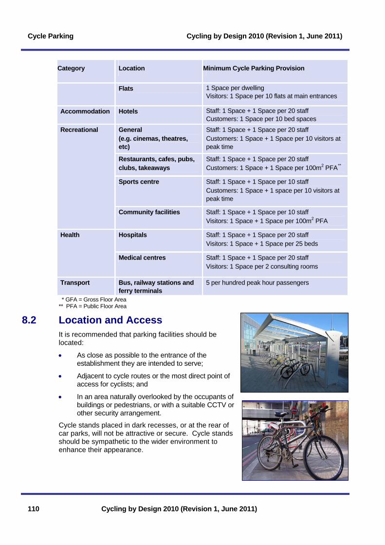
Cycle Parking Cycling by Design 2010 (Revision 1, June 2011)
Category Location Minimum Cycle Parking Provision
Flats 1 Space per dwelling Visitors: 1 Space per 10 flats at main entrances
Accommodation Hotels Staff: 1 Space + 1 Space per 20 staff Customers: 1 Space per 10 bed spaces
General (e.g. cinemas, theatres, etc)
Staff: 1 Space + 1 Space per 20 staff Customers: 1 Space + 1 Space per 10 visitors at peak time
Restaurants, cafes, pubs, clubs, takeaways
Staff: 1 Space + 1 Space per 20 staff Customers: 1 Space + 1 Space per 100m2 PFA**
Sports centre Staff: 1 Space + 1 Space per 10 staff Customers: 1 Space + 1 space per 10 visitors at peak time
Recreational
Community facilities Staff: 1 Space + 1 Space per 10 staff Visitors: 1 Space + 1 Space per 100m2 PFA
Hospitals Staff: 1 Space + 1 Space per 20 staff Visitors: 1 Space + 1 Space per 25 beds
Health
Medical centres Staff: 1 Space + 1 Space per 20 staff Visitors: 1 Space per 2 consulting rooms
Transport Bus, railway stations and ferry terminals
5 per hundred peak hour passengers
* GFA = Gross Floor Area ** PFA = Public Floor Area
8.2 Location and Access It is recommended that parking facilities should be located:
• As close as possible to the entrance of the establishment they are intended to serve;
• Adjacent to cycle routes or the most direct point of access for cyclists; and
• In an area naturally overlooked by the occupants of buildings or pedestrians, or with a suitable CCTV or other security arrangement.
Cycle stands placed in dark recesses, or at the rear of car parks, will not be attractive or secure. Cycle stands should be sympathetic to the wider environment to enhance their appearance.
110 Cycling by Design 2010 (Revision 1, June 2011)
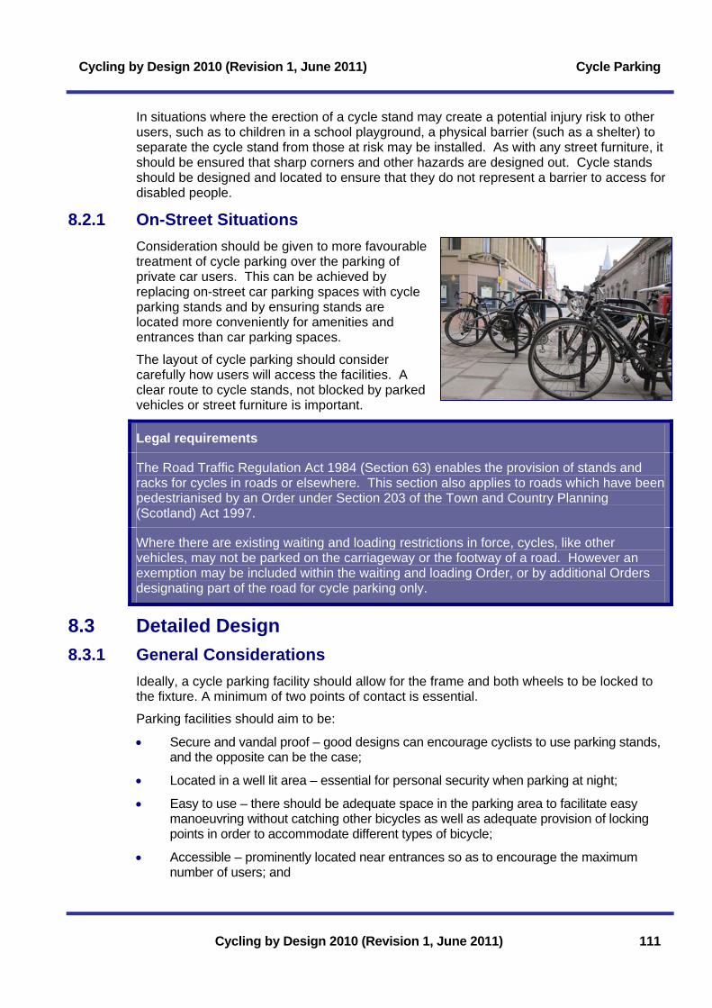
Cycling by Design 2010 (Revision 1, June 2011) Cycle Parking
In situations where the erection of a cycle stand may create a potential injury risk to other users, such as to children in a school playground, a physical barrier (such as a shelter) to separate the cycle stand from those at risk may be installed. As with any street furniture, it should be ensured that sharp corners and other hazards are designed out. Cycle stands should be designed and located to ensure that they do not represent a barrier to access for disabled people.
8.2.1 On-Street Situations Consideration should be given to more favourable treatment of cycle parking over the parking of private car users. This can be achieved by replacing on-street car parking spaces with cycle parking stands and by ensuring stands are located more conveniently for amenities and entrances than car parking spaces.
The layout of cycle parking should consider carefully how users will access the facilities. A clear route to cycle stands, not blocked by parked vehicles or street furniture is important.
Legal requirements
The Road Traffic Regulation Act 1984 (Section 63) enables the provision of stands and racks for cycles in roads or elsewhere. This section also applies to roads which have been pedestrianised by an Order under Section 203 of the Town and Country Planning (Scotland) Act 1997.
Where there are existing waiting and loading restrictions in force, cycles, like other vehicles, may not be parked on the carriageway or the footway of a road. However an exemption may be included within the waiting and loading Order, or by additional Orders designating part of the road for cycle parking only.
8.3 Detailed Design 8.3.1 General Considerations
Ideally, a cycle parking facility should allow for the frame and both wheels to be locked to the fixture. A minimum of two points of contact is essential.
Parking facilities should aim to be:
• Secure and vandal proof – good designs can encourage cyclists to use parking stands, and the opposite can be the case;
• Located in a well lit area – essential for personal security when parking at night;
• Easy to use – there should be adequate space in the parking area to facilitate easy manoeuvring without catching other bicycles as well as adequate provision of locking points in order to accommodate different types of bicycle;
• Accessible – prominently located near entrances so as to encourage the maximum number of users; and
Cycling by Design 2010 (Revision 1, June 2011) 111

Cycle Parking Cycling by Design 2010 (Revision 1, June 2011)
• Durable – a robust design will minimise the whole life cost of cycle parking provision.
The following types of cycle stand are considered:
• Sheffield stands;
• Wall loops;
• Cycle lockers; and
• Cycle stores.
Cycle stands which only grip the cycle by a wheel (including butterfly racks and concrete slots) are not recommended as they offer only limited security, can cause a trip hazard to pedestrians and can damage wheel rims.
8.3.2 Short to Medium Term Parking Generally Sheffield Stands and wall loops are recommended for short to medium term parking solutions.
8.3.2.1 Sheffield Stands Sheffield Stands are recommended for short stay parking, and in secure areas they can be a cost effective form of medium to long term parking. The stand provides good support to the cycle and allows the cyclist to secure both frame and wheels without risk of damage. Where necessary, a tapping rail is provided for visually impaired persons using a white cane at 200mm maximum above ground level (see Figure 8.1). This helps prevent people with visual impairments inadvertently colliding with the start of a line of stands.
Sheffield Stands For short and medium stay parking it is good practice for the Sheffield Stands to be situated as close to the destination point as possible, in frequent, well signed, small groups within appropriately illuminated areas. The stands should be located so that they do not cause a hazard and should be coloured/ tonally contrasted to assist visually impaired people with tapping rails provided where necessary.
A typical Sheffield Stand layout, intended for full size bicycles, is shown on Figure 8.1.
112 Cycling by Design 2010 (Revision 1, June 2011)
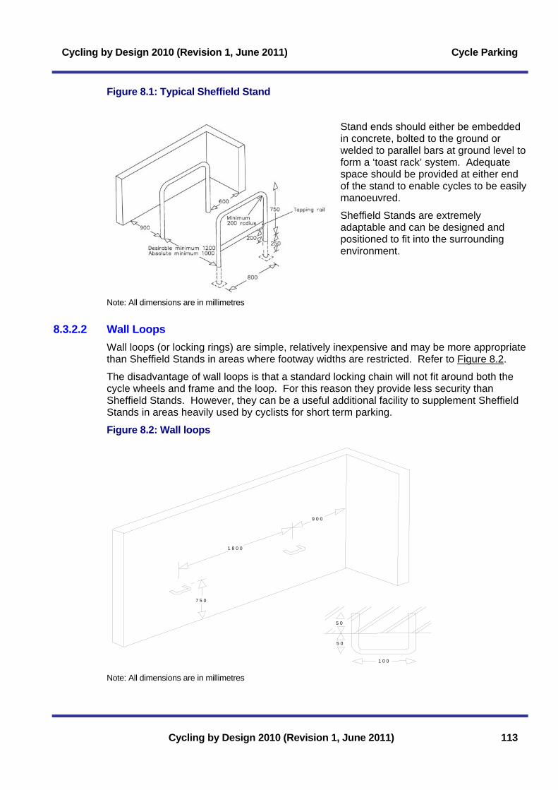
Cycling by Design 2010 (Revision 1, June 2011) Cycle Parking
Figure 8.1: Typical Sheffield Stand
Stand ends should either be embedded in concrete, bolted to the ground or welded to parallel bars at ground level to form a ‘toast rack’ system. Adequate space should be provided at either end of the stand to enable cycles to be easily manoeuvred.
Sheffield Stands are extremely adaptable and can be designed and positioned to fit into the surrounding environment.
Note: All dimensions are in millimetres
8.3.2.2 Wall Loops Wall loops (or locking rings) are simple, relatively inexpensive and may be more appropriate than Sheffield Stands in areas where footway widths are restricted. Refer to Figure 8.2.
The disadvantage of wall loops is that a standard locking chain will not fit around both the cycle wheels and frame and the loop. For this reason they provide less security than Sheffield Stands. However, they can be a useful additional facility to supplement Sheffield Stands in areas heavily used by cyclists for short term parking.
Figure 8.2: Wall loops
1 8 0 0
9 0 0
7 5 0
5 0
5 0
1 0 0
Note: All dimensions are in millimetres
Cycling by Design 2010 (Revision 1, June 2011) 113

Cycle Parking Cycling by Design 2010 (Revision 1, June 2011)
8.3.3 Medium to Long Term Parking Cycle lockers, locked cycle stores (compounds) or supervised areas within car parks are appropriate for medium and long term parking solutions.
8.3.3.1 Cycle Stores Cycle stores may be used to accommodate high levels of long-term cycle parking. They can either be under continuous supervision or have a shared key arrangement, where each cyclist has a key to the outer door.
Stands are provided internally to individually secure bicycles.
114 Cycling by Design 2010 (Revision 1, June 2011)
So
urce
: C
lack
man
nans
hire
C
ounc
il
Figure 8.3: Typical cycle store layout
Sheffieldstands
1.8m Absoluteminimumclearance
0.9m
1.2m Desirable Min1.0m Absolute Min
0.6m Desirable Min0.5m Absolute Min
2.0m Desirable Min1.8m Absolute Min
2.0m Desirable Min1.8m Absolute Min
0.9m
2.5m Desirableminimumclearance

Cycling by Design 2010 (Revision 1, June 2011) Cycle Parking
8.3.3.2 Cycle Lockers Well managed cycle lockers offer a secure parking facility, allowing accessories to be stored and providing weather protection (refer to Figure 8.3).
They are most appropriate in situations where regular users can take ownership of ‘their’ locker to ensure the locker is kept neat and tidy and locked at all times to prevent key copying and misuse.
Lockers may be operated by coin, token, credit card or key, or secured by a cycle lock and are commonly used at public transport interchanges. Advertising can be used to fund or support locker schemes, which may also ensure the lockers are placed in visible locations.
The main disadvantages with cycle lockers are that they are significantly more expensive than Sheffield Stands, take up space and may be visually intrusive. They are also unsuitable for occasional or short-term use. Adequate management arrangements need to be in place to maximise the use of lockers, provide maintenance and reduce misuse.
Lockers are most effective as part of a large cycle store. At relatively small transport interchanges where users require flexibility in travel choice, the most effective parking facilities in this instance are covered Sheffield Stands, which suit both the occasional and regular user. However, lockers may also supplement this provision.
Figure 8.4: Typical layout of a cycle locker scheme
1500mm1500mm
Parallel Configuration
1500mm
In Line Configuration
Recommended 1500mm access aisles around three sides of units.
Note: All dimensions are in millimetres
650mm 900mm typ. 1500mm19
00m
m15
00m
m15
00m
mUnit height : 1400mmDoor Opening : /50mmDoor Arcs : 95°
8.3.3.3 Car Parks
Supervised provision within car parks is a common form of commuter cycle parking. It has the benefit of offering increased security but without the additional cost of installing lockers or stores and may make efficient use of areas within the car park that may not otherwise be used. Cycle parking must be clearly visible, located in a supervised area or with CCTV coverage. Safe, direct, attractive and comfortable cycle routes should lead straight to the cycle parking area. For new car park layouts, this should be integral to the design.
Cycling by Design 2010 (Revision 1, June 2011) 115

Cycle Parking Cycling by Design 2010 (Revision 1, June 2011)
Provision in car parks Where users generally belong to the same group, at places of employment for example, lockable and covered cycle stores with Sheffield Stands or double-decker racks can provide secure and high quality facilities. Cycle parking should be placed conveniently at the entrance to the building or office and with direct access to cycle routes.
8.3.4 Traffic Signs Diagram Nos. 968 or 968.1 may be used to sign cycle parking. Direction signs, to Diagram Nos. 2603 and 2604, may be used to direct cyclists to cycle parking areas. The word ‘free’ may be included if appropriate.
116 Cycling by Design 2010 (Revision 1, June 2011)

Cycling by Design 2010 (Revision 1, June 2011) Public Transport Integration
9 Public Transport Integration 9.1 Importance of Integration....................................................... 117 9.1.1 Integration Principles ............................................................................117 9.1.2 New Developments...............................................................................118 9.2 Bike and Ride........................................................................... 118 9.2.1 Locations ...............................................................................................118 9.2.2 Parking ..................................................................................................119 9.2.3 Cycle Stations .......................................................................................120 9.3 Cycle Carriage ......................................................................... 120 9.3.1 Buses and Coaches..............................................................................120 9.3.2 Rail.........................................................................................................121 9.3.3 Ferries ...................................................................................................122 9.4 Public Cycle Hire ..................................................................... 122
Cycling by Design 2010 (Revision 1, June 2011)

Public Transport Integration Cycling by Design 2010 (Revision 1, June 2011)
Cycling by Design 2010 (Revision 1, June 2011)
Page intentionally left blank

Cycling by Design 2010 (Revision 1, June 2011) Public Transport Integration
Cycling by Design 2010 (Revision 1, June 2011) 117
9 Public Transport Integration 9.1 Importance of Integration
The integration of cycling and public transport provides a highly competitive door to door alternative to the private car for medium to long distance trips. This chapter provides guidance which may assist in promoting the integration of these modes when taken forward in consultation with transport operators.
By co-ordinating the different stakeholders in multi-modal journeys, alternative sources of funding may be combined. Potential sources of funding are as follows:
• Train Operating Companies’ (TOC) budgets;
• Developer contributions;
• Specific grant programmes run by statutory bodies;
• Lottery distributors;
• Central government; and
• Local government.
9.1.1 Integration Principles People are more likely to cycle if the journey to the public transport terminal is convenient and there is good, reliable provision of cycle parking or bicycle carriage to allow them to continue their journey using public transport. The main types of interchange are:
• Bike and Ride - Cycling to or from public transport where secure cycle parking is provided. The bicycle is left at this location and public transport is used for the remainder of the journey;
• Cycle Carriage - Cycling to an interchange point and travelling with the bicycle on the public transport service and using it at the other end to continue the journey; and
• Public Bike Hire - Utilising bicycle hire facilities at the public transport nodes to link journeys.
Factors affecting demand include the:
• Catchment of the population living within cycling distance of the public transport terminal;
• Importance of local destinations (leisure, work, shopping etc);
• Quality of cycle routes to and parking provision at the interchange;
• Frequency/ reliability of public transport services;
• Security, signing and promotion of the interchange and attractions/ destinations in the immediate vicinity;
• Provision of facilities for the carriage of bicycles on-board public transport services;
• Public awareness through complete partnerships and marketing; and
• Availability and cost of car parking and other transport alternatives.

Public Transport Integration Cycling by Design 2010 (Revision 1, June 2011)
9.1.2 New Developments In order to influence travel behaviour it is important that the future needs of the community are considered and met through good planning that takes place at an early stage to ensure an integrated approach to transport and land use planning. Trip generation and travel behaviour should be forecast to ensure that sustainable travel choices can be provided for within the design of new developments.
Opportunities must be taken within the planning process to make cycling, walking and public transport the modes of choice. The capacity of all transport options should be designed to achieve the targeted modal split that is desired or forecast.
Developments should be mixed use, close to public transport nodes, and developers should include direct links for cyclists to destinations both within and outwith the development to provide greater convenience than for motorised access.
Developers should work with local transport authorities, local travel plan advisors, residents and transport operators to support a high take-up of sustainable transport options. This should involve personalised travel planning and promotional initiatives as well as infrastructure measures.
9.2 Bike and Ride Bike and Ride facilities are normally formalised parking areas at or near to public transport terminals (generally bus or train stations, ferry terminals or general park and ride sites).
To provide a facility that will be successful, the location of the Bike and Ride site and the type of facilities to be provided need to be carefully planned.
118 Cycling by Design 2010 (Revision 1, June 2011)
Case study – Glenrothes to Markinch Station Fife Council received the Best Local Government Contribution at the ATOC National Cycle Rail Awards in 2007.
A new cyclepath provided by the Council between Markinch Station and Glenrothes made integrated cycling and commuter train travel easier for residents of Glenrothes by completing a link from the rail network into the existing cycle route network in the town.
The new cyclepath, developed principally along a disused railway branch line between the towns of Leslie and Markinch, created a high quality facility providing an opportunity for passengers to access the station using an alternative to the car. Cycle parking, access ramps and platform lifts allow cyclists coherent access to rail services.
Source: Hugh Connell
Source: Hugh Connell
9.2.1 Locations In order to maximise use of Bike and Ride facilities, they should be located at sites where:
• The public transport interchange is within convenient cycling distance of travellers’ trip origins. A maximum cycling time of 20 minutes is recommended as a guide, although this may be increased where the traveller’s overall journey is likely to be a long distance;

Cycling by Design 2010 (Revision 1, June 2011) Public Transport Integration
• The public transport interchange intercepts ‘journey to work’ routes;
• The length of the public transport section of the journey should be sufficient to deter the traveller from cycling for the whole of the trip. In general, it may be assumed that a cyclist who can complete a whole trip by cycling is likely to do so rather than splitting the journey between two forms of transport. Integrating public transport and cycling should therefore be aimed at medium/ long distance trips (i.e. >10km); and
• The journey from trip origin to the Bike and Ride facility should be safe, convenient and attractive to use. Cyclists are unlikely to use a facility, no matter how effective it is if the route to the facility is unpleasant to use.
9.2.2 Parking Cyclists using a public transport interchange may want to leave their cycles at the site all day, overnight or at the weekends. The provision of secure, high quality parking facilities is important. When the demand for secure long-term parking exceeds supply, users are often prepared to pay (pre-booking could be subject to a charge).
Prerequisites of any Bike and Ride facility should include:
Sou
rce:
Joh
n G
rimsh
aw
• A secure parking area which is both pre-bookable and available for casual use;
• Weather protection;
• Appropriate lighting;
• Appropriate signing (location should be easily found and prior to entering areas which conflict with busy pedestrian flows, but not diverted from a direct route to the interchange);
• Free or nominal charge for use;
• Well maintained and managed;
• Abandoned bikes and litter removed;
• Located within 20m of the most direct route to the interchange; and
• Open access lockers are often ‘reserved’ by users not known to the operator. Management of secure facilities by knowing the users and their contact details assists in maintaining that security.
For specific parking recommendations refer to Chapter 8.
Cycling by Design 2010 (Revision 1, June 2011) 119
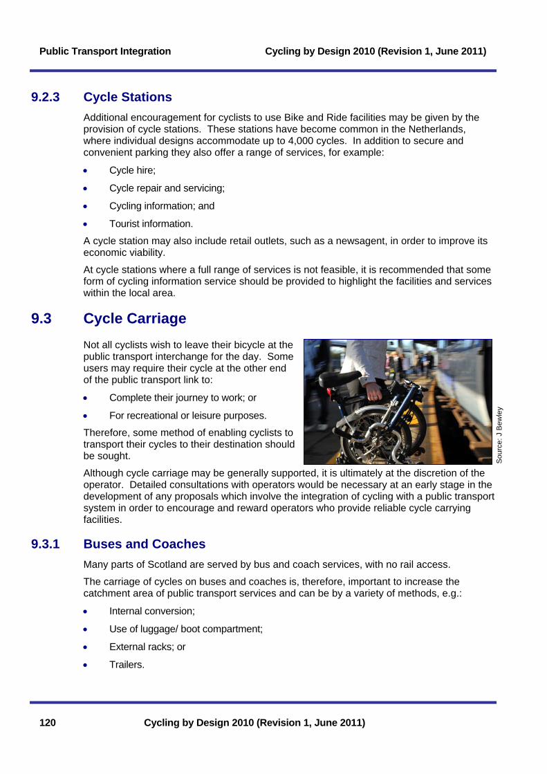
Public Transport Integration Cycling by Design 2010 (Revision 1, June 2011)
9.2.3 Cycle Stations Additional encouragement for cyclists to use Bike and Ride facilities may be given by the provision of cycle stations. These stations have become common in the Netherlands, where individual designs accommodate up to 4,000 cycles. In addition to secure and convenient parking they also offer a range of services, for example:
• Cycle hire;
• Cycle repair and servicing;
• Cycling information; and
• Tourist information.
A cycle station may also include retail outlets, such as a newsagent, in order to improve its economic viability.
At cycle stations where a full range of services is not feasible, it is recommended that some form of cycling information service should be provided to highlight the facilities and services within the local area.
9.3 Cycle Carriage Not all cyclists wish to leave their bicycle at the public transport interchange for the day. Some users may require their cycle at the other end of the public transport link to:
120 Cycling by Design 2010 (Revision 1, June 2011)
• Complete their journey to work; or
• For recreational or leisure purposes.
Therefore, some method of enabling cyclists to transport their cycles to their destination should be sought.
Although cycle carriage may be generally supported, it is ultimately at the discretion of the operator. Detailed consultations with operators would be necessary at an early stage in the development of any proposals which involve the integration of cycling with a public transport system in order to encourage and reward operators who provide reliable cycle carrying facilities.
Sou
rce:
J B
ewle
y
9.3.1 Buses and Coaches Many parts of Scotland are served by bus and coach services, with no rail access.
The carriage of cycles on buses and coaches is, therefore, important to increase the catchment area of public transport services and can be by a variety of methods, e.g.:
• Internal conversion;
• Use of luggage/ boot compartment;
• External racks; or
• Trailers.
Cycling by Design 2010 (Revision 1, June 2011) Public Transport Integration
Cycling by Design 2010 (Revision 1, June 2011) 121
Internal conversions: Flexible space available for passengers in wheelchairs on buses over 22 seats must be provided under the Disability Discrimination Act 2005. Cycles may be accommodated in this space when it is not in use by a wheelchair passenger. To store the cycle safely inside the vehicle, luggage straps should be provided. The Vehicle Inspectorate will need to approve any permanent securing devices. This is unlikely to be appropriate on busy commuter routes, where passenger demand may exceed capacity and is generally unreliable if taken into account with the needs of disabled people.
Use of luggage/ boot compartment: Storage of cycles in the luggage/ boot compartment may result in the vehicle, cycle and other luggage being damaged unless securing devices are fitted. Unless the cycle is a fold up type, it is also likely to take up a large proportion of the available storage space. Folding cycles are particularly suited to intermodal travel and are generally acceptable as hand luggage by public transport operators. However, these are less advantageous for long distance travel where loading and unloading is infrequent.
External racks: Carriage of cycles by racks on the front, rear or roof of the bus has become popular worldwide. However, this method is limited to moderately low flow cycle routes as most racks can only hold a maximum of five cycles. External racks do not provide weather protection.
Cycle racks able to carry up to two bikes on the rear of the bus are in use on a number of services in the UK. Vehicles in the UK often have a CCTV camera to provide the driver with assurance that the cycles are secure at all times, and to monitor loading and manoeuvring.
Trailers: Trailers have proved both popular and practical with many overseas operators. They are legally permitted for use with UK buses, where the combined length does not exceed 18m. Trailers provide a means of carrying a large numbers of cycles without having to alter the interior design of the bus, and are especially appropriate where heavy cycle flows are anticipated, for example to popular tourist destinations. Smaller buses with trailers can be an excellent solution for carrying touring cyclists to/ from their set-off point, such as one of the Western Isles ferry terminals.
9.3.2 Rail 60% of the population lives within a 15 minute cycle ride of a rail station. Integrating cycling trips effectively with rail travel increases the catchment population of the rail station and provides more flexibility for the user.
Cyclists travelling short distances by rail prefer a flexible system with cycle storage in every carriage. Single cycle storage areas are suitable for cyclists on longer-distance rail trips.
When considering the carriage of bikes on rail services, a number of factors need to be addressed:
• Train operators generally wish to maximise the number of passengers who can be accommodated through high density seating arrangements;
• Rolling stock commissioned now will be in service for the next 20 to 30 years, with a major internal refurbishment at 15-20 years. The opportunity to provide purpose-built rolling stock with integral cycle facilities may, therefore, be limited in the near future and going forward should be specified within franchise and other agreements;
• Current rolling stock can take at least two cycles in a convertible seating or luggage area and frequently carry 1-2 cycles in doorway vestibules. This is not desirable and raises safety issues. For personal safety, cycles should be stored in a recognised place, where they cannot cause injury; and

Public Transport Integration Cycling by Design 2010 (Revision 1, June 2011)
• Limited supply means that a reservation system may be required to guarantee cycle carriage, which in turn reduces accessibility and demand.
Design should avoid straps and moving parts where possible, as these require maintenance and can be untidy. Any system which hangs the cycle by the wheel must restrain suspended parts against swinging around and secure a wide range of wheel sizes.
The provision of flexible space may comprise an area of tip-up seats which may be used for cycles, wheelchairs and pushchairs when the train is under-utilised or by passengers during peak hours. However, this arrangement can cause conflict between different users and is unsuitable where there is high demand for this type of space.
An alternative method is the installation of ceiling hooks in larger trains, which enable the cycle to stand upright, therefore providing an efficient use of space. However, although useful for fit cyclists, assistance is required for those unable to lift their cycle.
Sou
rce:
Hug
h C
onne
ll
9.3.3 Ferries The carriage of bicycles on ferries is standard practice by ferry operators, with bikes secured on car decks. This service is provided free of charge in Scotland with the cyclist only paying for a foot passenger fare. This policy encourages cycling tourism to Scotland’s islands on a world-class ferry network matched with some of the best cycling to be had anywhere.
9.4 Public Cycle Hire Public cycle hire schemes are innovative schemes of rental or free bicycles in urban areas catering for a variety of short trips. They:
• Can be used for daily mobility including one-way-use;
• Are part of the public transport system;
• Differ from traditional, mostly leisure-oriented bicycle rental services as they provide fast and easy access; and
• Have diversified in organisational layout with the business models and the applied technology towards “smart bikes” (i.e. rental process via a smartcard or mobile phone).
Cycle hire schemes are normally most suited to medium and large cities (> 200,000 population) with a strong commitment to sustainable urban planning and standards of bicycle infrastructure for safe and convenient cycling. Sufficient resources for a large scheme are normally required in order to achieve a real impact (NICHES (2006).
The common successful elements of bike hire schemes are:
• A dense network of docking stations;
• Sufficient urban space for expansion of cycle stations;
• Pricing structure to maximise turnover of use and encourage short trips;
• Smartcard and/ or credit card payment system;
122 Cycling by Design 2010 (Revision 1, June 2011)

Cycling by Design 2010 (Revision 1, June 2011) Public Transport Integration
• Strong management of distribution and maintenance; and
• Third party implementation and management responsibility, often tied to wider city advertising contracts.
Case study: Vélo’v in Lyon
The French city of Lyon encouraged thousands of its citizens and visitors to use the bicycle as their urban transport mode within a few short months.
A major part of this was the introduction of a Public Cycle Hire scheme. Each of the 2,000 bicycles available at racks throughout the city centre is used on average 16 times on a typical summer day. Within the first six months of its introduction, two million trips had been made with the bicycles, replacing around 150,000 car trips. In combination with an increase in the use of private bicycles, overall bike use levels rose by 44% within a year.
Source: Bob Laughton, USA
Public cycle hire models for smaller towns and cities are under development in Scotland and elsewhere. Local authorities with drive, enthusiasm and the necessary vision and ambition are encouraged to discuss these with Transport Scotland.
Cycling by Design 2010 (Revision 1, June 2011) 123

Public Transport Integration Cycling by Design 2010 (Revision 1, June 2011)
124 Cycling by Design 2010 (Revision 1, June 2011)
Page intentionally left blank

Cycling by Design 2010 (Revision 1, June 2011) Construction and Maintenance
10 Construction and Maintenance 10.1 Introduction.................................................................................... 125 10.2 Construction Within the Carriageway......................................... 125 10.2.1 Ironwork.......................................................................................................125 10.2.2 Surface Condition........................................................................................125 10.2.3 Coloured Surfacing .....................................................................................125 10.3 Off-Carriageway Facilities ............................................................ 126 10.3.1 Pavement ....................................................................................................126 10.3.2 Drainage......................................................................................................128 10.3.3 Typical Construction Details .......................................................................128 10.4 Sustainability ................................................................................. 130 10.5 Lighting........................................................................................... 130 10.6 Maintenance Regime .................................................................... 130 10.6.1 Strategy .......................................................................................................131 10.6.2 Inspection, Assessment and Reporting .....................................................131 10.6.2.1 Safety Inspections.....................................................................................................132 10.6.2.2 Structural Condition/ Detailed Survey ......................................................................132 10.6.2.3 Inspection Frequency................................................................................................132 10.6.2.4 Recording ..................................................................................................................132 10.6.2.5 Defect Categories and Response Times.................................................................132 10.6.2.6 Fault Reporting..........................................................................................................133 10.6.3 Typical Maintenance Issues .......................................................................133 10.6.3.1 Negligence and Road Maintenance.........................................................................133 10.6.3.2 Surface Condition......................................................................................................133 10.6.3.3 Drainage ....................................................................................................................133 10.6.3.4 Verges and Overhanging Branches.........................................................................134 10.6.3.5 Sweeping...................................................................................................................134 10.6.3.6 Signs and Markings...................................................................................................134 10.6.3.7 Lighting Maintenance................................................................................................134 10.6.3.8 Winter Maintenance ..................................................................................................134
List of Tables Table 10.1: Typical pavement construction – urban location 127 Table 10.2: Typical pavement construction – rural location 128 Table 10.3: Defects and response times 133 List of Figures Figure 10.1: Typical construction – cycleway adjacent to kerbed carriageway 128 Figure 10.2: Typical construction - rural cycleway adjacent to carriageway (unkerbed) 129 Figure 10.3: Typical construction - rural cyclepath remote from carriageway 129
Cycling by Design 2010 (Revision 1, June 2011)

Construction and Maintenance Cycling by Design 2010 (Revision 1, June 2011)
Cycling by Design 2010 (Revision 1, June 2011)
Page intentionally left blank
Cycling by Design 2010 (Revision 1, June 2011) Construction and Maintenance
Cycling by Design 2010 (Revision 1, June 2011) 125
10 Construction and Maintenance 10.1 Introduction
Construction and maintenance are important aspects of any cycle facility. The quality of surfaces and edge details are particularly important to cyclists, who are more vulnerable to minor defects and poor construction than other road users. It is therefore important to ensure that construction details and materials for the cycle facility are appropriate and that a suitable maintenance regime is established.
Designers should ensure that the the materials and level of construction specified for cycle facilities are appropriate for purpose and that over specification does not lead to needlessly expensive facilities. However, the specification used should seek to ensure the least amount of future maintenance required as possible.
10.2 Construction Within the Carriageway On roads which permit cycling, and on roads where cycle facilities are incorporated within the carriageway space, the construction and maintenance of the cycle route should be clearly associated with that of the carriageway itself. Designers should assess:
• The location of ironwork (manholes, gullies etc);
• The standard of surface available; and
• Coloured surfacing.
10.2.1 Ironwork Ideally, ironwork should not be located within the cyclist’s desire line. On existing carriageways where this is not feasible, ironwork should be reset so that it is flush with the carriageway surface. Any gratings should be oriented so that they run at right angles to the direction of cycle flow and damaged ironwork should be replaced.
On new schemes, hardstrips and designated cycle facilties shall be free of ironwork. If gullies are required they should either be side-entry gullies or be offset from the edge of the running surface.
10.2.2 Surface Condition The surface of a cycle facility should have an even profile, be free of major defects and conform to the Specification for Highway Works. Where necessary, defects should be rectified in accordance with the maintenance requirements.
10.2.3 Coloured Surfacing The use of coloured surfacing to identify areas of the carriageway where other vehicles are discouraged from entering is recommended. There should be a consistent approach to the use of surface colouring as indiscriminate use may reduce its effectiveness (refer to TA 81/99). Where coloured surfacing is used, it may be applied over the entire length of the cycle facility or just at junctions.
The most common colours used are red and green, but the colour should be selected with regard to wider environmental considerations. The impact of bright colours in a rural

Construction and Maintenance Cycling by Design 2010 (Revision 1, June 2011)
126 Cycling by Design 2010 (Revision 1, June 2011)
environment can be both intrusive and downgrading to the surrounding landscape. The overall visual effect of the coloured surfacing in combination with the standard white road markings should be considered.
A coloured carriageway surface may be achieved by the use of coloured aggregates, fillers and binders in the surface course mix or by the surface application of a coloured material. The most common materials used are:
• Thermoplastic paint;
• Resin based materials with coloured chips;
• Coloured macadam; and
• Slurry seal.
When selecting the most appropriate material for a particular location, the following should be assessed:
• Ride quality and skid resistance;
• Adhesion to existing surface;
• Colour retention, durability and maintenance requirements; and
• Cost.
10.3 Off-Carriageway Facilities The construction details used for for an off-carriageway cycle facility will vary depending on the rural or urban nature of the route, whether it is adjacent to or remote from the road carriageway and on the characteristics of any adjacent carriageway. For further advice on off-carriageway facilities refer to Chapter 6.
The construction design will also be influenced by the facility’s purpose and expected level of use, construction methods available, the available budget for construction and maintenance, and aesthetic and environmental considerations.
It is important to note, however, that cyclists require a smooth, even surface with no upstand.
10.3.1 Pavement The loading requirements of cycleways and cyclepaths are far lower than for roads. Therefore in the design of pavements for cycle facilities, criteria such as cost, accessibility and environmental considerations outweigh the structural requirements.
Bound pavement layers must be sufficient to protect the subgrade from environmental effects and to withstand the loading induced by shrinkage or freeze/ thaw cycles. The pavement may also be required to withstand the loading from occasional vehicle overrun, and from construction and maintenance vehicles. Ground investigation is fundamental and the design may have to be enhanced over soft ground to cope with this traffic.
Pavement construction based on road construction practice may be justified only in locations where frequent vehicle overrun is considered likely.
Consideration should be given to the surface level tolerances specified when using thin bituminous layers laid directly onto sub-base to ensure the specified depths of materials are achieved in construction. The tolerance stated in Clause 702.2 of the Specification for

Cycling by Design 2010 (Revision 1, June 2011) Construction and Maintenance
Cycling by Design 2010 (Revision 1, June 2011) 127
Highway Works should be amended to ensure that the depth of the bituminous layers cannot be laid to less than that specified in the design.
In all cases, the pavement formation should to be sprayed with an approved non-toxic weedkiller.
Guidance on the suitability of a range of surface types for pedestrians, cyclists and equestrians may be found in DMRB. (TA 91/05)
Handlaid surfaces such as block-paving are not generally suitable for cyclists due to ride quality, though these may be considered over short distances and where they suit the surrounding environment.
Unbound surfaces are generally unsuitable for use on commuter routes as they are less durable and subject to dirt and dust. Bituminous surfacing may be applied on unbound surfaces where considered necessary.
Where equestrians share well-used rural off-road routes with cyclists and walkers, it is desirable to provide a parallel track for horses; ideally a short, hard-wearing and resillient turf. Bound surfaces are generally unsuitable for horses, except over short lengths.
Typical pavement constructions are provided in Tables 10.1 and 10.2 for guidance only. Designers should also refer to Section 10.4 for information on the use of sustainable materials that should be considered.
Table 10.1: Typical pavement construction – urban location
Construction type Pavement course Layer details
Surface course 30mm Hot Rolled Asphalt (Cl 910)
Binder 50mm Dense Asphalt Concrete (Cl 906)
Flexible
Sub-base 150mm Type 1 granular material (Cl 803)
Surface course 40mm Granolithic Concrete (Cl 1106)
Base 75mm 25/37.5 Concrete (Cl 1704)
Rigid
Sub-base 150mm Type 1 granular material (Cl 803)
Surface course 200 x 100 x 65mm precast Rectangular Concrete Block Paving (Cl 1107) or Clay Pavers (Cl 1108)
Base 40 +/- 10mm bedding layer of Sharp Sand or Crushed Rock Fines
Paving or pavers
Sub-base 150mm Type 1 granular material (Cl 803)

Construction and Maintenance Cycling by Design 2010 (Revision 1, June 2011)
Table 10.2: Typical pavement construction – rural location
Construction type Pavement Layer details
Surface course 30mm Hot Rolled Asphalt (Cl 910) or 30mm Close Graded Asphalt Concrete (Cl 912)
Binder 40mm Dense Asphalt Concrete (Cl 906)
Flexible surfacing
Sub-base 200mm Type 1 granular material (Cl 803)
Surface course Combined surface course and binder, 60mm Close Graded Asphalt Concrete (Cl 912)
Flexible surfacing
Sub-base 200mm Type 1 granular material (Cl 803)
Running curface 75mm binding material (Cl.920) Unbound surfacing
Sub-base 150mm Type 1 granular material (Cl 803)
10.3.2 Drainage Where drainage ditches are required they should be at least 0.5m away from the edge of the route. On urban routes the preferred option is for cycleways to fall toward the carriageway and for surface water to be drained using the road drainage network.
Where a kerb or delineator strip separates cycleways or footways vertically, 300mm gaps should be provided to allow the surface water to drain. The frequency of the gaps will be dependent on the overall drainage design.
10.3.3 Typical Construction Details This section provides examples of typical design details for off-carriageway cycle facilities.
Figure 10.1: Typical construction – cycleway adjacent to kerbed carriageway
Fall=2.5%
Surface CourseBinder Course
Subbase
300x100mm Class ST 1concrete kerb foundation and haunch
200x50mm flat-toppedP.C heel kerb, laid flush
FORMATION
Kerb detail asrequired
375x150mm Class ST1concrete kerb foundation
and haunch
Typical road drainageRefer to note ii
Margin. (refer to note iii)
128 Cycling by Design 2010 (Revision 1, June 2011)

Cycling by Design 2010 (Revision 1, June 2011) Construction and Maintenance
Notes: i) Figure to be read in conjunction with Tables 10.1 and 10.2. ii) Road drainage to be used to drain cycleway. iii) Segregation between NMUs and road vehicles can be enhanced by provision of a margin of coloured textured
surfacing on the cycleway side of the kerb. Refer to Chapter 6, Table 6.3. iv) Where a margin is provided, cycleway width beyond the margin should comply with Chapter 6, Table 6.2. v) In rural areas the flat top heel kerb may be omitted and replaced with edge detail as illustrated in Figure 10.2
Figure 10.2: Typical construction - rural cycleway adjacent to carriageway (unkerbed)
Fall=2.5%
Surface courseSubbase
300mm min.Edge
300mm min.Edge
FORMATION
Type B filter material to Clause 505
Filter drain to HighwayConstruction Details
Existingcarriageway
Existing verge
Notes: i) Figure to be read in conjunction with Table 10.2. ii) Road drainage to be used to drain cycleway. iii) Segregation between the cycleway and adjacent carriageway shall be maximised. Margin between the
carriageway and the cycleway shall be in accordance with Chapter 6, Table 6.3 and not less than 1.0m.
Figure 10.3: Typical construction - rural cyclepath remote from carriageway
Minimum 60mm deep layer of DBM(14mm stone). Path to have minimum
2.5% camber on dismantled railway, fallto suit tie-ins at disused road.
2500mm Shared cyclepath
Formation to be sprayed with approvednon-toxic weedkiller
Minimum 100mm deep sub-base ofType 1, compacted to refusal.
Use additional Type 1 to blind off anyexposed geotextile, and build up edgeof path. Difference between level ofpath edge and verge to be between40mm and 60mm.
Desirable width of soft verge 500m
Geotextile
3500mm
500mm
Absolute minimum width of Type 1verge to be 300mm. Desirableminimum width to be 500mm.
FORMATION
Notes: i) Figure to be read in conjunction with Table 10.2. ii) Appropriate drainage to be provided if necessary.
Cycling by Design 2010 (Revision 1, June 2011) 129

Construction and Maintenance Cycling by Design 2010 (Revision 1, June 2011)
130 Cycling by Design 2010 (Revision 1, June 2011)
10.4 Sustainability The designer must consider sustainability and durability in accordance with Transport Scotland’s startegy of promoting these issues in the Construction Industry. Where appropriate, recycling should be considered and the adoption of innovative materials and techniques encouraged.
Examples include:
• Warm, Half Warm and Cold mix asphaltic materials using asphaltic planings, emulsions and foamed bitumen;
• Recycled type 1 sub-base as unbound surfacing where appropriate;
• Tyre bales to enhance problematic foundations and increase drainage paths; and
• Local aggregates to reduce transport costs.
Following implementation, Transport Scotland’s Carbon Management System will enhance the designer’s capability to assess the carbon implications of design options, alternative material specifications and infrastructure durability.
10.5 Lighting Cycle routes which run on or adjacent to the carriageway will often benefit sufficiently from the carriageway lighting. Off-carriageway routes may require separate lighting provision. Cycle routes which run adjacent to an unlit carriageway should not be lit as this can cause difficulties for drivers.
The assessment of whether lighting provision is required should be based on local factors. In an urban development it is recommended that, where appropriate and feasible, routes should be lit, particularly at crossing points. It may be necessary to consult local residents to assess requirements.
It is not normally necessary to provide lighting for cycle routes in rural areas unless there are specific requirements. These may include:
• High flows of non motorised users (NMUs), particularly on adjacent and shared use routes;
• Routes with specific dangers such as intersections with rights of way or on routes that do not meet the required geometric standards;
• Identified school or commuter routes; and
• Routes through any underpass (subject to environmental impact).
Lighting for cyclists and pedestrians should be designed in accordance with BS EN 13201-2:2003, Table 3, which details the average and minimum horizontal luminance required.
Clearance to lighting columns should be provided in accordance with Chapter 6, Table 6.3.
At crossing points on lit roads, the lighting source should always be located close to and downstream of the crossing so that the NMUs are seen in silhouette by approaching vehicles.
10.6 Maintenance Regime The maintenance authority will be responsible for the preparation and delivery of a suitable maintenance regime for the cycle facility. The principles of the maintenance regime are:

Cycling by Design 2010 (Revision 1, June 2011) Construction and Maintenance
Cycling by Design 2010 (Revision 1, June 2011) 131
• To deliver statutory obligations of the authority;
• To provide effective management of the cycle facility;
• To safeguard the long term future of the asset of the cycle facility; and
• To be responsive to the needs of users and the community.
These principles are to be incorporated into a network management regime with the following core objectives:
Safety
• Complying with the statutory obligations; and
• Meeting users’ needs.
Serviceability
• Ensuring availability;
• Achieving integrity;
• Maintaining reliability; and
• Enhancing quality.
Network Sustainability
• Minimising costs over time;
• Maximising value to the community; and
• Maximising environmental contributions.
These core objectives provide the basis for the maintenance regime, the overall management of the cycle facility and the prioritisation of funds.
10.6.1 Strategy The maintenance authority will be responsible for the development and implementation of a suitable maintenance strategy for the facility. The main components of the strategy are:
• An inventory of all elements of the cycleway;
• A management system for inspecting, reporting, recording and prioritising actions; and
• Method of financing any works.
10.6.2 Inspection, Assessment and Reporting The maintenance authority will be responsible for the regular inspection, assessment and reporting of the facility. The three key areas for inspection are:
• Safety;
• Service; and
• Structural condition/ detailed.
As a result of each inspection the findings should be prioritised in terms of response required:
• Immediate action required;
Construction and Maintenance Cycling by Design 2010 (Revision 1, June 2011)
132 Cycling by Design 2010 (Revision 1, June 2011)
• Prompt action required; and
• Routine action required.
10.6.2.1 Safety Inspections The main purpose of the safety inspections is to identify any defects that represent an immediate hazard, a potential hazard or where there is a risk of rapid deterioration that would result in a hazardous defect by the next safety inspection.
10.6.2.2 Structural Condition/ Detailed Survey Detailed inspections are required to identify non-reactive defects which can be prioritised and included in a programme of planned maintenance, in order to protect the asset. These may be conducted at the same time as the safety inspections.
10.6.2.3 Inspection Frequency
Inspection frequency should be set in the context of the overall policy and maintenance strategy of the authority. Ideally the frequency of inspections will not exceed two months for safety inspections and twelve months for detailed inspection. These inspections will be carried out on cycle or preferably on foot.
10.6.2.4 Recording A list of items to be addressed in inspections is given below:
• Debris including but not limited to: leaf litter, broken glass, fallen tree/ branches, stones, gravel, litter, spillage or contamination of the running surface. It should be noted that it is the responsibility of the relevant local authority to clear litter;
• Vandalism/ damage to signs, walls, fences, gates;
• Potholes, cracks and deterioration of path surface;
• Path edge deterioration;
• Missing or broken manhole covers/ ironwork;
• Blocked drains/ off-lets - water on the path surface;
• Sight lines inhibited by foliage or other features;
• Missing/ worn markings; and
• Vegetation overgrowing the path surfaces or verges.
10.6.2.5 Defect Categories and Response Times Category 1 - Those defects as defined under the appropriate road maintenance contract that represent an immediate hazard or a potential hazard.
Category 2 - Those defects that are not Category 1 defects but:
• Involve the risk of structural deterioration;
• Constitute a reduction in safety;
• Constitute a reduction in the level of service or amenity; and
• Constitute an environmental threat.

Cycling by Design 2010 (Revision 1, June 2011) Construction and Maintenance
Cycling by Design 2010 (Revision 1, June 2011) 133
Table 10.3 gives examples of defects and response times required.
Table 10.3: Defects and response times
Defects Action Response time
Category 1 If possible make safe during inspection or make arrangements to protect the public.
24 hours
Category 2
Record the defects and include in the programme of routine/ cyclic works.
The programme shall be submitted to the Director for approval prior to commencing works.
Routine/ cyclic programme
Action taken may be a temporary measure. Permanent repairs should be carried out in accordance with the appropriate road maintenance contract.
10.6.2.6 Fault Reporting
Even with frequent inspections, it is not always possible for a maintenance authority to be aware of all the faults along a cycle route. Some authorities have attempted to overcome this by encouraging the general public to report maintenance needs such as potholes, blocked gullies, raised manhole covers etc. Such schemes may prove useful to cyclists and consideration should be given to publicity/ signing etc. of these where appropriate.
10.6.3 Typical Maintenance Issues
10.6.3.1 Negligence and Road Maintenance
Legal action can be brought in respect of loss, injury or damage resulting from a negligent failure to maintain a road (e.g. a cycle route). Action can be taken for damages either in common law, or for breach of a statutory duty.
10.6.3.2 Surface Condition Cyclists are affected by surface condition more than motorists, therefore regular detailed inspections should be conducted and any defects noted. The following types of defects should be repaired promptly:
• Ridges, projections, sharp edges, cracks and gaps greater than 10mm;
• Potholes and small area depressions greater than 20mm which are creating hazards;
• Rocking slabs; and
• Worn covers which may constitute a hazard to cyclists in wet conditions. These should be replaced where necessary.
10.6.3.3 Drainage Standing water more than 10mm deep should be noted and corrected, hence it is suggested that a safety inspection be undertaken after heavy rain. Gullies and other gratings, which have gaps more than 20mm wide, parallel to the line of movement of cyclists, should be modified or replaced. Broken or cracked gullies or covers in danger of collapse should be replaced. Gullies and other gratings should not rock or protrude the pavement surface.

Construction and Maintenance Cycling by Design 2010 (Revision 1, June 2011)
134 Cycling by Design 2010 (Revision 1, June 2011)
10.6.3.4 Verges and Overhanging Branches
Cycle route verges will require periodic maintenance to prevent the encroachment of verge soil and growth onto the cycle route. Overhanging branches and protruding hedges should be cut back and cleared as and when necessary to maintain safety standards and sight lines. Grass growth that reduces the width of the cycle route should also be cut back with at least two cuts per year required. Consideration should be given to edge details that restrict the growth of grass and weeds, for example a 300mm strip of Type B drainage stone laid adjacent to a cyclepath (as illustrated on Figures 10.2).
Siding out should be carried out under cyclic maintenance and as required before routine maintenance works, for example prior to surface dressing. Siding out should be carried out either manually or mechanically, and extend up to and including edging. Care should be taken to ensure that any siding out machinery that is employed does not cause damage to the existing surface.
10.6.3.5 Sweeping Sweeping is required to reduce the incidence of punctures. Not only can punctures be potentially dangerous, but also frequent punctures can quickly deter cyclists from using a cycle route. Coarse mechanical road brushes and backpack blowers are efficent in dealing with different forms of debris that can develop on cycle routes. Isolated occurrences of broken glass, hedge trimmings, potholes, spillage or contamination of the surface course etc. should rectified as and when they occur.
Debris from carriageways is deposited in channels or gutters by passing traffic and is likely to accumulate in cycle lanes and other areas of the road predominantly used by cyclists. Therefore, regular sweeping and general maintenance of the road channels and gullies is important to cyclists’ safety.
10.6.3.6 Signs and Markings Signs and markings require regular maintenance. These should be inspected to check their colour, retro-reflective properties, general performance, surface protective treatment and structural condition.
10.6.3.7 Lighting Maintenance Maintenance of lighting on urban commuter and local access routes should be to the same level as adjacent streets.
10.6.3.8 Winter Maintenance Urban Areas: In urban areas, on Commuter and Access Routes, standard maintenance arrangements should continue throughout the year. This should include the clearance of snow, and the de-icing of cycle facilities.
Rural Areas: In rural areas, standard maintenance arrangements should be maintained where practicable. It is recognised that this is unlikely to be feasible on some remote cyclepaths during winter and maps/ publicity material should advise of possible winter closure. Appropriate warning and other signs should be erected as necessary.
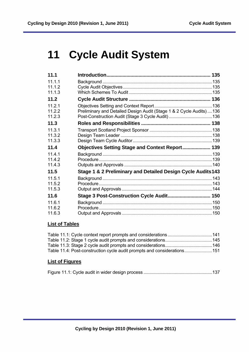
Cycling by Design 2010 (Revision 1, June 2011) Cycle Audit System
11 Cycle Audit System 11.1 Introduction.............................................................................. 135 11.1.1 Background ...........................................................................................135 11.1.2 Cycle Audit Objectives..........................................................................135 11.1.3 Which Schemes To Audit .....................................................................135 11.2 Cycle Audit Structure ............................................................. 136 11.2.1 Objectives Setting and Context Report ................................................136 11.2.2 Preliminary and Detailed Design Audit (Stage 1 & 2 Cycle Audits) ....136 11.2.3 Post-Construction Audit (Stage 3 Cycle Audit) ....................................136 11.3 Roles and Responsibilities .................................................... 138 11.3.1 Transport Scotland Project Sponsor ....................................................138 11.3.2 Design Team Leader ............................................................................138 11.3.3 Design Team Cycle Auditor..................................................................139 11.4 Objectives Setting Stage and Context Report..................... 139 11.4.1 Background ...........................................................................................139 11.4.2 Procedure..............................................................................................139 11.4.3 Outputs and Approvals .........................................................................140 11.5 Stage 1 & 2 Preliminary and Detailed Design Cycle Audits143 11.5.1 Background ...........................................................................................143 11.5.2 Procedure..............................................................................................143 11.5.3 Output and Approvals ...........................................................................144 11.6 Stage 3 Post-Construction Cycle Audit................................ 150 11.6.1 Background ...........................................................................................150 11.6.2 Procedure..............................................................................................150 11.6.3 Output and Approvals ...........................................................................150
List of Tables
Table 11.1: Cycle context report prompts and considerations .....................................141 Table 11.2: Stage 1 cycle audit prompts and considerations.......................................145 Table 11.3: Stage 2 cycle audit prompts and considerations.......................................146 Table 11.4: Post-construction cycle audit prompts and considerations.......................151
List of Figures
Figure 11.1: Cycle audit in wider design process .........................................................137
Cycling by Design 2010 (Revision 1, June 2011)

Cycle Audit System Cycling by Design 2010 (Revision 1, June 2011)
Cycling by Design 2010 (Revision 1, June 2011)
Page intentionally left blank

Cycling by Design 2010 (Revision 1, June 2011) Cycle Audit System
Cycling by Design 2010 (Revision 1, June 2011) 135
11 Cycle Audit System 11.1 Introduction
All trunk road works (including land use development proposals impacting upon the trunk road) are to be subject to Cycle Audit. This is also commended to other users of Cycling by Design.
11.1.1 Background Cycle Audit is separate from Road Safety Audit and Accessibility Audit detailed in HD19/03 and Disability Discrimination Act: Good Practice Guide for Roads (Transport Scotland (2009)), respectively. Whilst Cycle Audits may make reference to cyclist safety and/ or accessibility issues, it forms only part of a larger audit process to raise the standard of design.
It shall be the responsibility of the Design Team to make design decisions on the basis of these three different sources of information. This will ensure that safety, cyclist and accessibility issues are balanced within the project.
11.1.2 Cycle Audit Objectives The objectives of cycle audit are as follows:
• To ensure that the current and future needs of cyclists within a scheme are recognised and developed;
• To ensure that the infrastructure provided for cyclists is in accordance with current best practice; and
• To ensure that there are no elements of infrastructure within a scheme that will endanger or unnecessarily impede cyclists or other users.
The Cycle Audit is a means of checking design decisions in a formal and consistent manner throughout the design process. The extent of work required to carry out the Cycle Audit will depend on the scale, type and complexity of the scheme.
11.1.3 Which Schemes To Audit All capital investment schemes that impact upon trunk road infrastructure shall be subject to Cycle Audit. These include:
• All major and minor road improvements;
• Traffic management schemes;
• Traffic calming schemes;
• Structural maintenance schemes;
• Developments impacting upon the trunk road; and
• Re-determination schemes.

Cycle Audit System Cycling by Design 2010 (Revision 1, June 2011)
136 Cycling by Design 2010 (Revision 1, June 2011)
11.2 Cycle Audit Structure The Cycle Audit System is structured in four parts:
• Objectives Setting and Context Report;
• Preliminary Design Audit (Stage 1 Cycle Audit);
• Detailed Design Audit (Stage 2 Cycle Audit); and
• Post-Construction Audit (Stage 3 Cycle Audit).
Details of the methodology and approvals process for each of these parts are given in Sections 11.4-11.6. Programming of these within the overall design process is shown in Figure 11.1.
An overview of each part of the process is as follows:
11.2.1 Objectives Setting and Context Report The Objectives Setting stage identifies considerations towards cycling infrastructure as part of the scheme. The Objectives Setting stage shall be completed before the commencement of the design process.
The output from this stage shall be a Context Report. The Context Report shall contain a list of cycling specific Design Objectives for the scheme. These Objectives shall be set to meet the specific local needs of present and future cyclists using the scheme. The Objectives shall be referred to by designers when making decisions throughout the design process.
The scheme will be audited against the Design Objectives during the audit process.
11.2.2 Preliminary and Detailed Design Audit (Stage 1 & 2 Cycle Audits) Audits shall be undertaken towards the end of both the preliminary and detailed design stages. The outputs from the Preliminary and Detailed Design audits shall be Stage 1 and Stage 2 Cycle Audit Reports respectively.
The purpose of the Cycle Audit is to verify that the design:
• Meets with the objectives identified in the Audit Context Report; and
• Complies with the best practice standards identified elsewhere in this document.
Where objectives or standards have not been met, the Audit Report shall detail actions demonstrating how they will be achieved. Where an objective or standard cannot be met due to constraints (i.e. cost, engineering, land etc.) the Audit Report shall document the reasons.
At preliminary design Cycle Audit stage, these actions shall be carried forward to the detailed design for inclusion. At the detailed design Cycle Audit stage, actions shall be incorporated in the final design drawings issued for tender.
11.2.3 Post-Construction Audit (Stage 3 Cycle Audit) The Post-Construction Cycle Audit shall be undertaken when the scheme is substantially complete and prior to opening for public use. The output from the Post-Construction Audit shall be the Stage 3 Post-Construction Audit Report.

Cycling by Design 2010 (Revision 1, June 2011) Cycle Audit System
The purpose of the Post-Construction Audit is to:
• Verify that the built scheme meets with the scheme objectives; and
• Identify any additional measures which would contribute to safe, comfortable and efficient passage of cyclists through the scheme.
The Construction Audit Report shall detail actions demonstrating how they will achieve Design Objectives or contribute to the safe, comfortable and efficient passage of cyclists. In the latter case, these may be due to issues that may not have been apparent or foreseeable at the design stage.
If deemed appropriate by the Transport Scotland Project Sponsor, these actions may be instructed for implementation during the defects period of the contract.
Figure 11.1: Cycle audit in wider design process
Cycling by Design 2010 (Revision 1, June 2011) 137

Cycle Audit System Cycling by Design 2010 (Revision 1, June 2011)
138 Cycling by Design 2010 (Revision 1, June 2011)
11.3 Roles and Responsibilities The individuals that shall be involved in the Cycle Audit process and their respective roles and responsibilities are as follows:
11.3.1 Transport Scotland Project Sponsor The Transport Scotland Project Sponsor is a person within Transport Scotland responsible for ensuring the progression of a scheme design in accordance with Transport Scotland’s policy and procedures.
The responsibilities of the Transport Scotland Project Sponsor are to:
• Specify the terms of reference of the Cycle Audit and define at which stages of the design process Cycle Audits will be required;
• Provide the Design Team Leader with all pertinent background information in relation to the scheme context and objective setting (e.g. previous STAG assessment reports, traffic counts, accident statistics, cycling demand etc.);
• Approve the Design Team Cycle Auditor presented by the Design Team Leader;
• Review the final copy of the Cycle Audit reports from the Design Team;
• Authorise any deviation from best practice where the Cycle Audit identifies that standards or objectives cannot be met due to scheme constraints;
• Approve Audit Reports and issue instruction to proceed to the next stage of design; and
• Consider and instruct any additional works identified in the post-construction audit.
11.3.2 Design Team Leader The Design Team Leader is a person within the Design Team responsible for managing the scheme design.
The responsibilities of the Design Team Leader are to:
• Propose a Design Team Cycle Auditor, compliant with the requirements detailed below to the Transport Scotland Project Sponsor;
• Formally appoint the Design Team Cycle Auditor following Transport Scotland approval;
• Ensure that the Objective Setting and Cycle Audit stages are included within the design programme;
• Ensure that the Audit Context Report is understood by all design team members and that its objectives are recognised during development of the design;
• Check and approve Cycle Audit Reports and submit to the Transport Scotland Project Sponsor;
• Liaise with the Transport Scotland Sponsor and seek approval for the Audit Reports; and
• Ensure that the agreed actions within the Audit Reports are incorporated within the design.
Cycling by Design 2010 (Revision 1, June 2011) Cycle Audit System
Cycling by Design 2010 (Revision 1, June 2011) 139
11.3.3 Design Team Cycle Auditor The Design Team Cycle Auditor is the person within the Design Team responsible for undertaking the cycle audit process in accordance with the procedures detailed in this document.
The Design Team Cycle Auditor shall be a senior member (≥5 years post-qualification design experience) of the project design team who is a cyclist. The Cycle Auditor must have experience of designing for the needs of cyclists and the effects of design proposals on existing and latent cycling demand.
The Design Team Leader must propose the Design Team Cycle Auditor to the Transport Scotland Project Sponsor for approval, detailing qualifications and experience relevant to the role. The Design Team Cycle Auditor and the Design Team Leader can be the same person.
The responsibilities of the Design Team Cycle Auditor are:
• To understand background data, including consultation with representative local groups, on the needs of cyclists affected by the scheme proposals;
• To agree the Design Objectives through preparation of the Audit Context Report;
• At the points during the design process agreed with the Transport Scotland Project Sponsor, audit the design against the Design Objectives and good practice design;
• Produce Cycle Audit reports detailing the finding of the audits and actions for inclusion in the design; and
• Advise members of the design team on cycling related matters during the design process, with specific reference to the Design Objectives and data defined in the Context Report.
11.4 Objectives Setting Stage and Context Report
11.4.1 Background The Objectives Setting stage shall identify requirements to meet cyclists’ needs as part of the scheme design (or development impacting upon the trunk road). These requirements shall be formalised through the development of Design Objectives. The Objectives and the background information to support them shall be summarised in a Context Report.
The Context Report shall be used by the design team as a reference document during design. The Design Team Cycle Auditor shall audit the design against the Design Objectives within the Context Report and Cycling by Design.
11.4.2 Procedure The Objectives Setting stage and preparation of the Context Report shall be undertaken by the Design Team and agreed by the Design Team Cycle Auditor.
The first task in the Objective Setting stage is the collection of pertinent data to properly assess the needs of current and potential cyclists that may be affected by the scheme. Where previous work has been undertaken or data gathered, this shall be supplied to the Design Team Leader by the Transport Scotland Project Sponsor.

Cycle Audit System Cycling by Design 2010 (Revision 1, June 2011)
140 Cycling by Design 2010 (Revision 1, June 2011)
Data that should be considered will include cycle and traffic flows, accident statistics, current and future trip generators and attractors. In addition to this factual data, a review of policy at a local, regional and national level with impact on the scheme should be considered. The views of stakeholders must be sought, including representative user groups.
Using this information to identify potential problems for cyclists, the Design Team Cycle Auditor shall agree a series of objectives for the scheme with the Design Team. It is important to note that the objectives should be focused towards overcoming the problems and not delivering a particular solution. It is the responsibility of the design team to determine what the most appropriate solution may be, in the context of the wider design constraints.
Earlier work may include a STAG appraisal or environmental assessment. In certain cases, these documents may already include high level scheme objectives. However, the purpose of the Cycle Audit Objective Setting Stage is to refine any previous work into specific design objectives, to ensure that the objectives cover the specific, day-to-day needs of cyclists using the scheme. The objectives within the context report should be focused on the detail of the scheme.
A list of prompts and key issues for consideration in the Objective Setting process is shown in Table 11.1. This list should not be considered as exhaustive and the Audit should also consider any other local factors, which may have an impact on the scheme.
A proposal map showing the existing and proposed cycle facilities in the area influenced by the scheme is a useful means of summarising the data in the Cycle Audit Context Report. This can provide a useful at-a-glance summary of the issues which may assist in ensuring the objectives are properly addressed.
11.4.3 Outputs and Approvals The completed Context Report shall be checked by the Design Team Leader. Once the Design Team Leader is content that the Objective Setting Process and Context Reporting have been completed satisfactorily, he or she shall countersign the report and forward to the Transport Scotland Project Sponsor for approval.
Thereafter, the Transport Scotland Project Sponsor will coordinate any amendments to the Context Report or project deemed necessary to comply with the policies or procedures of Transport Scotland.
The project should not normally progress to preliminary design until such time as the Context Report has been prepared and approved. The final approved Cycle Audit Context Report shall be made available to the Design Team as a reference document for design by the Design Team Leader.

Cycling by Design 2010 (Revision 1, June 2011) Cycle Audit System
Cycling by Design 2010 (Revision 1, June 2011) 141
Table 11.1: Cycle context report prompts and considerations
Project information Route and project title
Transport Scotland Route Manager
Transport Scotland Project Sponsor
Design Organisation
Local Authority
Developer
Design Team Cycle Auditor
General scheme description
Outline of the proposed scheme detailing the extent and content of the proposed works and any effect of the works on the surrounding land uses and transport infrastructure. Plan of works to be provided.
Strategic objectives Local Authority transport plans (including cycle network plans)
Core Path Plans
Transport Scotland policies
Client Brief in relation to cycling
Planning objectives for the scheme
Maintenance
Existing site characteristics
Traffic flows
Cycle flows
Traffic speeds
Traffic flow content % HGV
Pedestrian flows
Equestrian flows
Accident data
Stakeholder Consultation
(to be carried out where relevant throughout the process)
Local Authority and/ or Transport Scotland Cycling Officer
Local Authority Safe Routes to Schools Officer
Disability groups
Local cycling groups
British Horse Society Scotland
Sustrans (where NCN or disused railway is affected)
Public transport operators

Cycle Audit System Cycling by Design 2010 (Revision 1, June 2011)
142 Cycling by Design 2010 (Revision 1, June 2011)
Trip generators and desire lines
Residential areas
Employment centres
Retail facilities
Education facilities
Hospitals
Hotels and restaurants
Public transport interchanges
Tourist attractions
Community and leisure facilities
Parks, squares and public places
Observation of cycling activity on footways, paths, the wrong way on one-way streets, on pedestrian areas, cycle parking capacity etc
Existing facilities – paths, bridleways, NCN and local routes, Public rights of way
Transport modelling results
User needs Consider and document:
Demographic of users (e.g. children, college students, working age commuters, tourists/ visitors, elderly people) and skill levels (novice, intermediate, experienced) to be catered for
Trip purpose (utility or leisure) and importance of journey time, quality of experience
Opportunities Proposed local land use developments
Traffic management and other transport schemes
Off road cycle routes
Bus lanes
Traffic calmed areas
Areas free from motorised traffic
Speed restricted zones
Pedestrian areas
Quiet residential streets
Disused railway lines
Routes through parks
Wide footways
Paths
Canals with tow paths
Existing bridleways

Cycling by Design 2010 (Revision 1, June 2011) Cycle Audit System
Cycling by Design 2010 (Revision 1, June 2011) 143
Constraints Rivers or railway lines
Steep gradients
Secluded areas
Speed limits > 30mph in urban areas
Speed limits > 50mph in rural areas
One-way streets
High traffic flows
High HGV content in traffic flows
Outputs Based on the above, the Context Report should include:
Details of the existing and proposed facilities
Details of key trip generators and desire lines
Summary of user and stakeholder needs
Summary of constraints and opportunities within the study area
Design Objectives, which should be SMART (Specific, Measurable, Achievable, Relevant and Time-Bound).
11.5 Stage 1 & 2 Preliminary and Detailed Design Cycle Audits
11.5.1 Background Formal Cycle Audits shall be undertaken at agreed stages in the design process. Most projects will require Cycle Audits close to the completion of the Preliminary and Detailed design stages respectively. For smaller projects, the two stages may be combined and there will be just one audit. The Transport Scotland Project Sponsor shall define the stages at which audits will be required.
The purpose of the Cycle Audits is to verify that the design meets with the scheme objectives and best practice defined within Cycling by Design. The Context Report shall be referred to when undertaking and reporting on the audit.
11.5.2 Procedure The Preliminary (Stage 1) and Detailed Design (Stage 2) Cycle Audits shall be undertaken by the Design Team Cycle Auditor.
The Design Team Cycle Auditor shall be issued with a set of scheme drawings by the Design Team Leader. The drawings should reflect the final Preliminary or Detailed design as closely as possible and should be issued towards the end of the design process.
The Design Team Cycle Auditor should visit the site as part of the Cycle Audit.
During the Cycle Audit, the following shall be reviewed by the Design Team Cycle Auditor. For ease of reference, the audit process is split into two components:
• Longitudinal Facilities Audit, where the project or any part of the project includes provision for cyclists on the road carriageway or with cycleways, or cyclepaths and

Cycle Audit System Cycling by Design 2010 (Revision 1, June 2011)
144 Cycling by Design 2010 (Revision 1, June 2011)
• Crossing Facilities Audit, where the project or any part of the project has a requirement for cyclists to cross the existing or proposed road network (either at a junction or at a carriageway crossing point).
A list of prompts and key issues for consideration during the audit is shown in Table 11.2. This list should not be considered as exhaustive and the Audit shall consider any local factors, which may have an impact on the scheme.
The audit shall be undertaken taking account of the scheme objectives defined in the Context Report. At the Detailed Design Cycle Audit, the Audit shall also review the design against the actions defined at the Preliminary Design Cycle Audit.
11.5.3 Output and Approvals Each Cycle Audit undertaken shall be documented in a Cycle Audit Report.
The Cycle Audit Report shall:
• Summarise the background of the project and the findings of the Context Report;
• Summarise the items raised at the Preliminary Design Cycle Audit (Detailed Design Cycle Audits only);
• List the scheme objectives and make comment on how adequately they have been addressed; and
• List issues with the current design in terms of meeting objectives and best practice and detail actions to address them.
The completed Audit Report shall be checked by the Design Team Leader. Once the Design Team Leader is content that the Audit has been completed satisfactorily, he or she shall countersign the report and forward to the Transport Scotland Project Sponsor for approval.
Thereafter, the Transport Scotland Project Sponsor will coordinate any amendments to the Audit Report or project deemed necessary to comply with the policies or procedures of Transport Scotland.
The project should not normally progress to the next stage design until such time as the Audit Report has been approved.
The findings of the Cycle Audit shall be made available to the Design Team by the Design Team Leader to allow changes to be made to the design where appropriate.

Cycling by Design 2010 (Revision 1, June 2011) Cycle Audit System
Cycling by Design 2010 (Revision 1, June 2011) 145
Table 11.2: Stage 1 cycle audit prompts and considerations
Project information Route and project title
Transport Scotland Route Manager
Transport Scotland Project Sponsor
Design organisation
Local Authority
Developer
Design Team Cycle Auditor
Date of audit
Assessment of design objectives
Compliance with Client Project Brief
Assessment against Context Report Design Objectives
Have the recommendations from the previous audit stage been incorporated into the design (where applicable)?
Have representations of user groups been incorporated into the design?
Longitudinal Facilities Audit
Assessment of the appropriateness of the proposed facilities for cyclists:
- Does the route alignment suit the identified user needs?
- Does the route and surface type and quality suit the identified user needs?
- Are cyclists sufficiently segregated from traffic, pedestrians and equestrians (where relevant)?
- At a high level, is the route gradient likely to be appropriate?
- Is the capacity of the route sufficient?
- Are cyclists sufficiently protected from the effect of climatic conditions?
- Are the best opportunities for route development taken?
- Is there sufficient integration with other cycle routes and other modes?
Crossing Facilities Audit
Is the crossing location and type the most appropriate for the needs of users?
General New or amended Traffic Regulation Orders
Roads (Scotland) Act Orders
Land acquisition

Cycle Audit System Cycling by Design 2010 (Revision 1, June 2011)
146 Cycling by Design 2010 (Revision 1, June 2011)
Table 11.3: Stage 2 cycle audit prompts and considerations
Project information Route and project title
Transport Scotland Route Manager
Transport Scotland Project Manager
Design Organisation
Local Authority
Developer
Design Team Cycle Auditor
Date of Audit
Assessment of design objectives
Compliance with Client Project Brief
Assessment against Context Report Design Objectives
Have the recommendations from the previous audit stage been incorporated into the design (where applicable)?
Have representations of user groups been incorporated into the design?
Longitudinal Facilities Audit
Assessment of the appropriateness of the proposed facilities for cyclists:
- On-carriageway
- Off-carriageway
- Safety and integration of all types of users
- Traffic Flows (AADT)
- Pedestrian Flows (peak hour and off-peak)
- Cyclist Flows (peak hours)
- Speed Limits
- Traffic 85th %ile Speed
- % HGV Content
Effect of any approved Departure from Standard and measures for mitigating impact
Effect of any Relaxation of Standard and measures for mitigating impact
Desirable Minimum and Absolute Minimum width criteria
Segregation of pedestrians, cyclists and equestrians
Vertical alignment
Gradient and cross-fall
Horizontal alignment and curve widening where required
Sight distances
Stopping distances
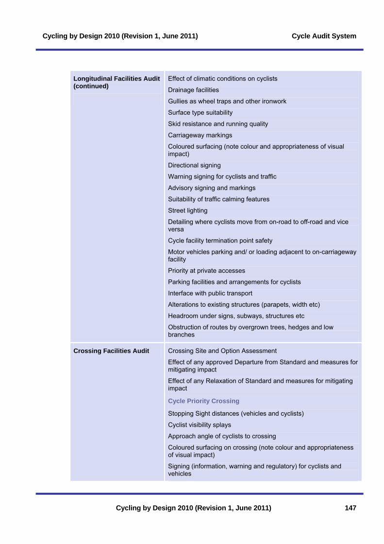
Cycling by Design 2010 (Revision 1, June 2011) Cycle Audit System
Cycling by Design 2010 (Revision 1, June 2011) 147
Longitudinal Facilities Audit (continued)
Effect of climatic conditions on cyclists
Drainage facilities
Gullies as wheel traps and other ironwork
Surface type suitability
Skid resistance and running quality
Carriageway markings
Coloured surfacing (note colour and appropriateness of visual impact)
Directional signing
Warning signing for cyclists and traffic
Advisory signing and markings
Suitability of traffic calming features
Street lighting
Detailing where cyclists move from on-road to off-road and vice versa
Cycle facility termination point safety
Motor vehicles parking and/ or loading adjacent to on-carriageway facility
Priority at private accesses
Parking facilities and arrangements for cyclists
Interface with public transport
Alterations to existing structures (parapets, width etc)
Headroom under signs, subways, structures etc
Obstruction of routes by overgrown trees, hedges and low branches
Crossing Facilities Audit Crossing Site and Option Assessment
Effect of any approved Departure from Standard and measures for mitigating impact
Effect of any Relaxation of Standard and measures for mitigating impact
Cycle Priority Crossing
Stopping Sight distances (vehicles and cyclists)
Cyclist visibility splays
Approach angle of cyclists to crossing
Coloured surfacing on crossing (note colour and appropriateness of visual impact)
Signing (information, warning and regulatory) for cyclists and vehicles

Cycle Audit System Cycling by Design 2010 (Revision 1, June 2011)
148 Cycling by Design 2010 (Revision 1, June 2011)
Crossing Facilities Audit (continued)
Bend out offset from main road distance
Deviation from straight
Priority adjusted at private accesses to give priority to cyclists
Gullies located in crossing areas
Drop kerbs
Suitability for disabled users
Suitability for equestrians
Cycle Give Way Crossing
Stopping Sight distances (vehicles and cyclists)
Cyclist visibility splays
Approach angle of cyclists to crossing
Signing (information, warning and regulatory) for cyclists and vehicles
Crossing waiting area size
Capacity of refuges serving substantial generators (e.g. schools)
High Friction Surfacing for vehicles on approach to crossing
Crossing waiting times
Delay at crossing points
Street lighting
Gullies located in crossing areas
Drop kerbs
Pedestrian guardrail/ bollards/ chicanes
Suitability for disabled users
Suitability for equestrians
Signal Controlled Crossing
Compliance of toucan crossing with design guidelines
Cyclist visibility splays
Approach angle of cyclists to crossing
Crossing waiting area size
Stopping Sight distances (vehicles and cyclists)
Signing (information, warning and regulatory) for cyclists and vehicles
Advance stop lines
High Friction Surfacing for vehicles on approach to crossing
Crossing times at signal controlled crossings
Gullies located in crossing areas

Cycling by Design 2010 (Revision 1, June 2011) Cycle Audit System
Cycling by Design 2010 (Revision 1, June 2011) 149
Crossing Facilities Audit (continued)
Drop kerbs
Pedestrian guardrail/ bollards/ chicanes
Suitability for disabled users
Suitability for equestrians
Grade Separation
Underpass or bridge?
Cyclists and pedestrians to be segregated?
Stopping Sight distances (cyclists)
Subway layout: ramps, steps, gradients
Bridge/ underpass layout: ramps, steps, gradients, landings, parapets etc.
Underpass ceiling and wall surface finishes
Inter-visibility with other users for personal safety
Suitability for disabled users
Surfacing skid resistance
Lighting
Drainage
Wheeling channels
Suitability for equestrians
Roundabouts
Cyclists within the circulatory carriageway
Conversion of roundabout to continental style
Remote cycle facility
Roundabout bypassed
Suitability for equestrians
General New or amended Traffic Regulation Orders
Roads (Scotland) Act Orders
Land acquisition

Cycle Audit System Cycling by Design 2010 (Revision 1, June 2011)
150 Cycling by Design 2010 (Revision 1, June 2011)
11.6 Stage 3 Post-Construction Cycle Audit
11.6.1 Background The purpose of the Stage 3 Post-Construction Cycle Audit is to verify that the built scheme meets with the scheme objectives. It also aims to identify any additional measures not included within the design which would contribute to safe and efficient passage of cyclists through the scheme. The Context Report and the reports from the Design Cycle Audits shall be referred to when undertaking and reporting on the audit.
The Stage 3 Post-Construction Cycle Audit shall include a visit to the site and be undertaken as the works near completion or are being prepared for opening to the public.
11.6.2 Procedure The Stage 3 Post-Constrution Cycle Audit shall be undertaken by the Design Team Cycle Auditor.
The Design Team Cycle Auditor shall be issued with a set of as built drawings by the Design Team Leader prior to the commencement of the audit.
The Design Team Cycle Auditor should visit the site as part of the Cycle Audit. The scheme shall be viewed during both daylight and hours of darkness. The Cycle Auditor should cycle the scheme in both directions during the audit. A volunteer representative of either Sustrans (NCN route involved) or CTC (non-NCN route involved) and a representative of the appropriate local authority cycling unit, are to be invited to attend the Cycle Audit.
During the Cycle Audit, the following shall be reviewed by the Design Team Cycle Auditor. For ease of reference, the audit process is split into two components:
• Longitudinal Facilities Audit, where the project or any part of the project includes provision for cyclists on the road carriageway or with cycleways, or cyclepaths; and
• Crossing Facilities Audit, where the project or any part of the project has a requirement for cyclists to cross the existing or proposed road network (either at a junction or at a carriageway crossing point).
A list of prompts and key issues for consideration during the audit is shown in Table 11.4. This list should not be considered as exhaustive and the Audit shall also consider any other local factors, which may have an impact on the scheme.
The audit shall be undertaken taking account of the scheme objectives defined in the Context Report. The audit shall also review the design against the actions defined at the Detailed Design Cycle Audit.
11.6.3 Output and Approvals The Post-Construction Cycle Audit shall be documented in a Stage 3 Post-Construction Cycle Audit Report.
The Cycle Audit Report shall:
• Summarise the background of the project and the findings of the Context Report;
• Summarise the items raised at the Detailed Design Cycle Audit;

Cycling by Design 2010 (Revision 1, June 2011) Cycle Audit System
Cycling by Design 2010 (Revision 1, June 2011) 151
• List the scheme objectives and make comment on how adequately they have been addressed; and
• List issues with the current design in terms of meeting objectives and best practice and detail actions to address them.
The completed Audit Report shall be checked by the Design Team Leader. Once the Design Team Leader is content that the Audit has been completed satisfactorily, he or she shall countersign the report and forward to the Transport Scotland Project Sponsor for approval.
Thereafter, the Transport Scotland Project Sponsor will coordinate any amendments to the Audit Report or project deemed necessary to comply with the policies or procedures of Transport Scotland.
The Stage 3 Post-Construction Cycle Audit report may contain recommendations for additional works. Such recommendations shall be considered and, if deemed appropriate, instructed by the Transport Scotland Project Sponsor.
Table 11.4: Post-construction cycle audit prompts and considerations
Project information Route and project title
Transport Scotland Route Manager
Transport Scotland Project Sponsor
Design Organisation
Local Authority
Developer
Design Team Cycle Auditor
Date of Audit
Re-assessment of previous audit(s)
Have the recommendations from the previous audit been incorporated into the design?
Longitudinal Audit Appropriateness and continuity of facility
Effect of any approved Departure from Standard and measures for mitigating impact
Effect of any Relaxation of Standard and measures for mitigating impact
Forward visibility and stopping sight distance
Horizontal geometry
Vertical geometry
Cross-sectional geometry
Running quality and skid resistance
The use of coloured surfacing
Traffic calming

Cycle Audit System Cycling by Design 2010 (Revision 1, June 2011)
152 Cycling by Design 2010 (Revision 1, June 2011)
Longitudinal Audit (continued)
Space for cyclists passing build-outs
Segregation of pedestrians
The adequacy of drainage, potential for flooding
Water hazards including adjacent activities and associated safety equipment
Longitudinal edge details including drainage channels, gullies, kerbing boundary walls, fencing, landscaping, tree trunks and branches
Safety fencing and parapets
Avoidance of cattle grids/ gates/ barriers
Adjacent land uses
Parking
Bus lanes (with flow and contra-flow)
Coloured surfacing use.
Lighting for safety and security
Traffic signs and road markings and information for cyclists
Traffic Regulation Orders
Safety of other users
Termination of hardstrips
Merges/ diverges with all-purpose carriageways
Continuity and safety passing private accesses
Public transport connections: bus, train, air and ferry
Suitability for equestrians
Crossing Audit Type and appropriateness of crossing
Effect of any approved Departure from Standard and measures for mitigating impact
Effect of any Relaxation of Standard and measures for mitigating impact
Pedestrian Flows (peak hour and off-peak)
Cyclist Flows (peak hours)
Traffic Flows (AADT)
Traffic 85th %ile speed on approach to crossing point
Traffic % HGV Content
Vehicle driver visibility of crossing point
Visibility of traffic from crossing point
Traffic calming

Cycling by Design 2010 (Revision 1, June 2011) Cycle Audit System
Cycling by Design 2010 (Revision 1, June 2011) 153
Crossing Audit (continued) Proximity of adjacent junctions
Approach angle of cyclists to crossing
Drop kerbs
Waiting areas [edge & midpoint]
Segregation for pedestrians
Coloured surfacing use
Position of gullies and other ironwork
Crossing approaches: high skid resistant surfacing and warning signs for vehicles
Subway layout: ramps, steps, gradients, surfacing and personal security
Bridge layout: ramps, steps, gradients, landings, wheeling channels parapets etc
Signalised crossing layout and equipment
Pedestrian guardrail type
Lighting of crossing
Traffic signs, road markings and information for cyclists at junctions
Traffic Regulation Orders
Safety of other users
Forward visibility and stopping sight distance (vehicles and cyclists)
Negotiating roundabouts
Continuity and safety passing minor road priority junctions
Continuity and safety negotiating traffic light junctions
Continuity and safety negotiating grade separated junctions
Advance stop lines
Traffic signs and road markings and information for cyclists
Suitability for equestrians
Suitability for all disabled users

Cycle Audit System Cycling by Design 2010 (Revision 1, June 2011)
154 Cycling by Design 2010 (Revision 1, June 2011)
Page intentionally left blank

Cycling by Design 2010 (Revision 1, June 2011) Appendix A
Appendix A Legal Issues A.1 ....................................................................1 Principal LegislationA.1.1 The Roads (Scotland) Act 1984 ...............................................................1 A.1.2 Road Traffic Regulation Act 1984 ............................................................3 A.1.3 Town and Country Planning (Scotland) Act 1997....................................4 A.1.4 The Land Reform (Scotland) Act 2003.....................................................4 A.1.5 The Disability Discrimination Acts 1995 and 2005 (Equality Act 2010) ..5 A.2 Other Legislation..........................................................................6 A.2.1 Transport (Scotland) Act 2001..................................................................6 A.2.2 Countryside (Scotland) Act 1967..............................................................7 A.2.3 Traffic Calming Legislation .......................................................................7 A.2.4 National Parks (Scotland) Act 2000 .........................................................8 A.3 Order Making ................................................................................8 A.3.1 Traffic Regulation Orders (TROs) ............................................................8 A.3.2 Orders Extinguishing Vehicular Rights.....................................................9 A.3.3 Footway and Footpath Redetermination for Cycle Use...........................9 A.3.4 Redetermination of Pedestrian Subways and Footbridges ...................10 A.3.5 Other Orders ...........................................................................................10 A.3.6 Equestrian Access ..................................................................................10
Cycling by Design 2010 (Revision 1, June 2011)

Appendix A Cycling by Design 2010 (Revision 1, June 2011)
Cycling by Design 2010 (Revision 1, June 2011)
Page intentionally left blank

Cycling by Design 2010 (Revision 1, June 2011) Appendix A
Cycling by Design 2010 (Revision 1, June 2011) A1
A Legal Issues A.1 Principal Legislation
The following sections outline the legislative guidelines and legal considerations currently necessary to enable the development of a cycle facility within Scotland.
Provision of any type of cycle facility should rely on clear legal authority. Five Acts of Parliament provide the main sources of statutory authority for the provision of cycle facilities within Scotland:
• The Roads (Scotland) Act 1984;
• The Road Traffic Regulation Act 1984;
• The Town and Country Planning (Scotland) Act 1997;
• The Land Reform (Scotland) Act 2003; and
• The Disability Discrimination Acts 1995 and 2005.
Cycling by Design uses the non-statutory terms set out in Chapter 1 to define pedal cycle infrastructure i.e. Cycle Lane; Cycleway and Cyclepath. However, the legal definitions differ from this. This Appendix defines the legal terms that should be used by designers in the use of relevant acts. One critical aspect for designers to bear in mind in definining facilities is the general access right afforded by the Land Reform (Scotland) Act 2003 for all non-motorised users to all paths (unless exempted under Section 6 the Act).
A.1.1 The Roads (Scotland) Act 1984 In Section 151 of the Roads (Scotland) Act 1984 the following terms are defined and apply to all roads in Scotland:
“public road” means a road which a Roads Authority has a duty to maintain.
“road” means subject to Section 151(3) of the Roads (Scotland) Act 1984, any way (other than a waterway) over which there is a public right of passage (by whatever means and whether subject to a toll or not) and includes the road’s verge, and any bridge (whether permanent or temporary) over which or tunnel through which, the road passes; and any reference to a road includes a part thereof.
The parts of the road which are defined in Section 151(2) of the Act are:
• “Footway” the right of passage by foot only where it is associated with a carriageway.
• “Footpath” the right of passage by foot only where it is not associated with a carriageway.
• “Cycle track” the right of passage by pedal cycle only or by pedal cycle and foot only.
• “Carriageway” the right of passage by vehicles and pedal cycles.
Transport Scotland, an agency of the Scottish Government, is responsible for the trunk road network and Local Authorities are responsible for all public non-trunk roads. Section 4 of the Act sets out the circumstances where Local Authorities may act as agents for Scottish Ministers (formerly the Secretary of State for Scotland). Local Authorities are responsible for the cleansing of all public roads other than special roads or trunk roads (although by agreement they may cleanse trunk roads as agents for Scottish Ministers).

Appendix A Cycling by Design 2010 (Revision 1, June 2011)
A2 Cycling by Design 2010 (Revision 1, June 2011)
The following sections of the Roads (Scotland) Act 1984 are of direct relevance to the design and implementation of cycling infrastructure and facilities:
Section 20 gives power for local Roads Authorities to construct new roads, which by definition includes new cycle tracks. Upon completion they are entered on the list of public roads with the appropriate description.
Section 25 gives powers for the provision of footways.
Section 26 gives powers for the provision of pedestrian subways and footbridges and their lighting, maintenance etc.
Section 28 covers the provision of raised paving, barriers, walls etc. between footways, footpaths, cycle tracks, or carriageways, or on a cycle track so as to segregate users.
Section 31 covers the provision for drains, Section 35 the provision of lighting and Section 54 the provision of refuse bins.
Section 48 enables a Roads Authority to enter into an agreement for contribution by other persons for the provision or improvement of a road (including footpaths and cycle tracks).
Section 64 permits vehicles to be used on cycle tracks to construct, improve, maintain or cleanse them. Statutory undertakers require consent from the Roads Authority. Vehicles operated by the emergency services do not have explicit authority under this Act to use cycle tracks.
Section 68 gives powers for the stopping up of roads, but there may be a reservation of a means of passage along the road to be stopped up for pedestrians, cyclists, or both, plus the usual safeguards for statutory undertakers. Unopposed Orders promoted under this Section can be made by the road authority.
Section 71 gives information on the procedure in cases where there are objections to the Order and these are not withdrawn. The regulations referred to in the section of the Act are the Stopping Up of Roads and Private Accesses and the Redetermination of Public Rights of Passage (Procedure) (Scotland) Regs 1986 (No. 252(S.16)).
Sections 83-95 deal with obstructions, deposits or other dangers on or beside the road, and their removal or alleviation.
Section 100 states that it is an offence to paint, inscribe or affix anything on the surface of a road, or upon trees, traffic signs, milestones etc. without lawful authority or reasonable excuse.
Sections 103-119 cover the acquisition of land, either by agreement or by CPO.
Section 120 reminds anyone proposing or executing works in a road to have regard to the needs of disabled or blind persons.
Section 129 lists various offences, including at Sub-Section (5), driving, riding, leading etc. vehicles, horses, cattle, etc. along footways, footpaths, or cycle tracks. They may however be taken across such routes, and pedal cycles may be used on cycle tracks. Sub-Section (6) makes it an offence to park a motor vehicle wholly or partly on a cycle track.
Section 152(2) of the Roads (Scotland) Act 1984 in conjunction with Section 1(1) gives powers to redetermine the means of exercise of public right of passage along a public road or any part thereof. This is considered further in section A.3.4 of this appendix.

Cycling by Design 2010 (Revision 1, June 2011) Appendix A
Cycling by Design 2010 (Revision 1, June 2011) A3
A.1.2 Road Traffic Regulation Act 1984 This Act covers Traffic Regulation Orders (TROs), Parking Place Orders (including the provision of stands and racks for bicycles), compulsory purchase powers and traffic signs. Road Authorities may make TROs to prohibit, restrict or regulate the use of a road by traffic or any class of traffic (including pedestrians).
TROs are subject to the procedures prescribed in the Local Authorities’ Traffic Orders (Procedure) (Scotland) Regulations 1999/614.
Section 1 allows roads authorities to make TROs, which include prohibiting any class or classes of traffic from roads, or parts of roads, either generally or at specific times. Such an order could be used, for example, to create a traffic-free area for pedestrians only or, if the local road authority thought it appropriate, for pedestrians and cyclists.
Section 9 allows authorities to make Experimental TROs. Such Experimental Orders are limited to a maximum period of 18 months.
A TRO could also provide for with-flow or contra-flow cycle lanes in carriageways. For safety reasons a contra-flow lane should prohibit waiting, including loading and unloading, at all times on the side of the carriageway containing the cycle lane. A with-flow order should prohibit all waiting, except that loading and unloading may be permitted outside the working day.
The effect of a cycle lane order will be to prohibit, during the hours specified in that order, the use of that lane by certain classes of traffic. If access, by vehicles of any class, to premises situated adjacent to any road is prevented for a period in excess of 8 hours in any 24 hour period, the order will require the consent of Scottish Ministers (formerly the Secretary of State for Scotland) (Paragraph 13(1)(a) of Part II of Schedule 9) unless no relevant objections are made or, having been made, are withdrawn (Paragraphs 13(2) of Part II of Schedule 9).
Part IV of the Road Traffic Regulation Act 1984 enables the provision of off-street parking places for vehicles and authorises the use of any part of the road as a parking place.
These powers are extended by Section 63 of the Act to enable the provision, in roads and elsewhere, of stands and racks for cycles. This section also applies to roads which have been pedestrianised by an Order under Section 203 of the Town and Country Planning (Scotland) Act 1997.
Where there are existing waiting and loading restrictions in force, cycles, like other vehicles, may not be parked on the carriageway or the footway of a road.
However, on-street parking can be accommodated either through an exemption to the existing waiting and loading Orders, or by additional Orders designating part of the road for cycle parking only.
Sections 64 and 65 of the Act contain general provisions regarding traffic signs, including traffic signals and tactile markings. Traffic signs should comply with the current Traffic Signs Regulations and General Directions, or be specially authorised by Scottish Ministers (formerly the Secretary of State for Scotland).
Section 92 gives Road Authorities powers to erect bollards and other obstructions, to give effect to a TRO made under Section 1 or 9 of this Act.

Appendix A Cycling by Design 2010 (Revision 1, June 2011)
A4 Cycling by Design 2010 (Revision 1, June 2011)
A.1.3 Town and Country Planning (Scotland) Act 1997 The main source of planning law in Scotland is the Town and Country Planning (Scotland) Act 1997, as amended by the Planning etc. (Scotland) Act 2006. The 2006 Act replaced Part 2 of the 1997 Act which relates to development plans. Sections 3A to 3D of the 1997 Act (which were also added by the 2006 Act) set out arrangements for the preparation and publication of the National Planning Framework, a spatial plan for Scotland, and set out provisions under which planning authorities will carry out the preparation, examination and publication of strategic development plans and local development plans.
Of particular note is Part IX of the 1997 Act:
Sections 202 and 207 covers the stopping up or diversion of roads (except trunk and special roads) to enable development to be carried out in accordance with planning permission granted over part of the affected road. With regard to section 202 of the 1997 Act, it should be noted that the Scottish Ministers can order the stopping up of any road. Under section 207 of the 1997 Act a Local Authority can order the stopping up of a road which is not a trunk road or a special road.
Section 203 covers the extinguishment of the right of vehicles to use a road, i.e. the conversion of a road to a footpath or bridleway.
Section 205 gives provision for pedestrianisation schemes (which may exempt cyclists, access vehicles, statutory undertakings etc).
Section 208 covers the stopping up or diversion of footpaths and bridleways.
A.1.4 The Land Reform (Scotland) Act 2003 The Land Reform (Scotland) Act 2003 (hereafter referred to as the Land Reform Act) established the right of responsible access by all non-motorised users (including cyclists) to most land and inland waters, and therefore not merely to paths and rights of way. The Act gives local authorities the powers to facilitate this access right which applies to recreational, educational and some semi-commercial purposes. Under this Act, cyclists have lawful responsible access to almost all land, and the Scottish Outdoor Access Code sets out responsibilities for all parties from landowners to visitors. This Act supersedes large parts of the Countryside (Scotland) Act 1967.
Section 2 of the Act identifies that access rights must also be exercised responsibly by individuals. Section 3 places a duty on landowners to responsibly use and manage the land over which access rights are exercisable.
Section 6 sets out categories of land over which access rights are not exercisable. This includes playing fields, land contigous to and used for schools, land adjacent to a dwelling which would affect an individual’s privacy, land comprising building or engineering works and land on which crops are sown or are growing.
Crucially section 6.1D accedes to other legislation which prohibits, excludes or restricts public access in particular instances. This therefore includes legislation covering roads and railways (See Section A.3.4 on redetermination below). In practice, this means that cyclists cannot use footways designated under the Roads (Scotland) Act, despite the general access right asserted by the Land Reform Act.
Section 9 of the Act sets out conduct that is not covered by access rights. This includes being on or crossing land in or with a motorised vehicle or vessel, other than those constructed or adapted for use by a person with a disability.

Cycling by Design 2010 (Revision 1, June 2011) Appendix A
Cycling by Design 2010 (Revision 1, June 2011) A5
Section 10 of the Act places responsibility on Scottish Natural Heritage to draw up and issue a Scottish Outdoor Access Code. The Outdoor Access Code’s principal purpose is to explain what the term “responsible” means in practice for both users and landowners. This section of the Act (section 10.d) also highlights the need for owners of land excluded from access rights to have regard to access rights to land contiguous to their land. As a result of the Land Reform Act, the Scottish Outdoor Access Code came into effect from February 9th 2005, at the same time as the Act. A copy of the Code is available from Scottish Natural Heritage or can be found online at the Scottish Outdoor Access Code website. Section 2.7 of the Code clarifies “Recreational purposes”, as described under the Land Reform (Scotland) Act 2003, to include active pursuits such as cycling.
Under Section 13, the Act establishes a requirement for local authorities to assert, protect, and keep open and free from obstruction or encroachment any route over which access rights can be asserted (Section 13). In most authorities, this duty is carried out by Access Officers. Where a new development removes this right of access, the local planning authority must take this into account. Section 14 of the Act gives local authorities the powers to require landowners to remove any signs, obstructions or dangerous impediments with the purpose of deterring access. However, Section 12 enables local authorities to pass byelaws to restrict access rights if necessary.
Section 17 of the Act places a duty on Local Authorities to draw up a plan for a system of paths (“core paths”) sufficient to provide reasonable public access throughout its area. The designation of a route as a “core path” automatically supersedes all the restrictions contained within Section 6 (see also A.3.3).
Section 25 of the Act requires each Local Authority to establish for its area a body, to be known as the “local access forum” to carry out a range of functions in relation to local access and the powers under the Act.
A.1.5 The Disability Discrimination Acts 1995 and 2005 (Equality Act 2010) The Disability Discrimination Act (1995) (DDA 1995) places a duty on employers, educators and service providers to make reasonable adjustments to avoid discriminating against disabled people. This includes making adjustments to physical features which act as barriers to access for disabled people. Public functions were not covered by this Act.
The Disability Discrimination Act (2005) (DDA 2005) amends the DDA 1995 and extends the principles of Part III of the DDA 1995, which prohibits discrimination in the provision of goods, facilities and services and premises, to the delivery of public authority functions. This amendment also brings in new duties for public authorities, including Transport Scotland, to actively promote disability equality. Public authorities have a ‘general duty’ and most have ‘specific duties’. The general duty covers:
• Eliminating unlawful disability discrimination;
• Eliminating unlawful disability harassment;
• Promoting equality of opportunity;
• Taking steps to take account of disabled persons’ disabilities, even where that involves treating disabled persons more favourably than other persons;
• The need to promote positive attitudes towards disabled people;
• The need to encourage participation by disabled persons in public life.

Appendix A Cycling by Design 2010 (Revision 1, June 2011)
A6 Cycling by Design 2010 (Revision 1, June 2011)
The specific duties are intended to assist public authorities in meeting their ‘general duty’. In particular, the specific duties set out what public bodies should do to plan, deliver and evaluate actions to eliminate discrimination and promote equality, and to report on the activity.
Promoting inclusive environments is one of the key aims in meeting the ‘general duty’. For example, Transport Scotland’s policies, will have to ‘build in’ for disability while the Scottish Government’s overarching Disability Equality Scheme will take a coordinating approach to considering disabled peoples’ needs across all Scottish Government departments, agencies, and functions.
Guidance on the auditing process for cycle paths to bring them up a suitable standard was provided in the report: ‘National Cycle Network in Scotland, Auditing Access for Disabled People’ (Scottish Government (2004))’. Consultation with local disability groups could also highlight difficulties experienced by disabled users in utilising existing paths.
All necessary improvements required should be reviewed to determine which reasonable steps can be taken to provide access for disabled users. Local authority access officers can assist in the resolution of such issues. Physical ‘barriers’ which could make it impossible or unreasonably difficult for disabled people include:
• Access controls (gates, styles, bollards, etc.);
• Unsuitable path design (steep gradients, excessive crossfall, steps, lack of handrails, high kerbs, narrow path width, lack of resting places, etc.);
• Unsuitable path construction (uneven surface, inappropriate surface materials, breaks or gaps in surface, grates/ grills etc.).
Note that the provisions of the DDA 1995 and 2005 were incorporated within the Equality Act 2010 and the DDA 1995 and 2005 were repealed.
A.2 Other Legislation A.2.1 Transport (Scotland) Act 2001
Transport is mostly a devolved matter and is the responsibility of the Scottish Parliament. The Transport (Scotland) Act 2001 was the Scottish Parliament's first transport legislation and provided the legislative framework to improve transport planning, enable local authorities to implement road user charging, support quality bus measures and allow the establishment of the Integrated Transport Fund to support strategic transport projects via a central government grant.
Section 74 of the Act provides the legal framework for Home Zones in Scotland. It enables local authorities to designate home zones with a view to implementing measures for securing certain purposes, namely: to improve the safety of persons using the road; to improve or preserve the environment through which the road runs; to improve facilities and bring benefits to non-motorised vehicle users of the road; and for local authorities to implement to any extent their transport policies. It also enables Scottish Ministers to make regulations prescribing the procedures to be followed by local authorities when designating roads as home zones. These comprise the Home Zones (Scotland) (No. 2) Regulations 2002 and define a series of steps that local authorities must follow during the creation of a Home Zone.
Cycling by Design 2010 (Revision 1, June 2011) Appendix A
Cycling by Design 2010 (Revision 1, June 2011) A7
A.2.2 Countryside (Scotland) Act 1967 This Act gives powers to Local Authorities to provide recreation facilities in the countryside and enables Scottish Natural Heritage (SNH) through the Natural Heritage (Scotland) Act 1991 to assist authorities and others by grant.
The Countryside (Scotland) Act 1967 (hereafter referred to as the Countryside Act) is largely superseded by the Land Reform Act. However, parts of the Countryside Act are not repealed and some elements are still applicable in some situations. For example, the Countryside Act powers for public path creation, diversion, etc continue to be available for use on land where the Land Reform (Scotland) Act rights do not apply, even though they are repealed otherwise.
Section 39 enables SNH to propose long distance routes, defined as being an extensive journey on foot, on pedal cycle, or on horseback which for the whole or greater part of its length does not pass along roads mainly used by vehicles. In practice however, SNH now rarely pursues this aspect.
Section 45 of the Countryside Act also still gives powers for planning authorities to authorise the installation of stiles and gates on a public right of way, and to impose conditions on their maintenance.
Section 46 covers the installation of guide posts and direction notices on public rights of way, which are not public roads. Planning authorities also have a duty to keep public rights of way open and free from obstruction and can repair or maintain those which are not roads or footways. However, this aspect of the Countryside Act only applies in an increasingly rare number of cases where the Land Reform (Scotland) Act does not apply.
Rights of way (established under common law through a record of public use) remain in existence, and continue to be important on land exempt from the Land Reform Act. For example, farmyards are generally exempt from the access rights of the Land Reform Act (because they are regarded as the ‘curtilage’ of the farm buildings). However, if a Right of Way exists through a farmyard, then the public has the right to use that route under the pre-existing common law right of way.
A.2.3 Traffic Calming Legislation The Roads (Traffic Calming) Scotland Regulations 1994 and The Road Humps (Scotland) Regulations 1998 should be referred to when considering traffic calming interventions.
The Roads (Traffic Calming) (Scotland) Regulations 1994 cover:
• The types and purpose of traffic calming works;
• Those that a road authority should consult prior to traffic calming works;
• Restrictions on the construction of overrun areas and rumble devices;
• The placing of traffic signs; and
• The prohibition of certain traffic calming works.
The Road Humps (Scotland) Regulations 1998 revoked The Road Humps (Scotland) Regulations 1990 and cover:
• Dimensions and location of road humps;
• Placing of traffic signs;
• Exemptions for roads subject to 20mph speed limits or less; and
Appendix A Cycling by Design 2010 (Revision 1, June 2011)
A8 Cycling by Design 2010 (Revision 1, June 2011)
• Exemptions for those road humps constructed that conformed to the 1990 Regulations and were delivered before the 1998 Regulations.
The Road Humps and Traffic Calming (Scotland) Amendment Regulations 1999 amended some sections of the above regulations and came into force on the 28th April 1999.
Since 1999, The Road Humps and Traffic Calming (Scotland) Amendment Regulations 2002 also further amended the 1994 and 1998 Regulations and came into force on 1st October 2002.
A.2.4 National Parks (Scotland) Act 2000 The purpose of a National Park Authority is to ensure that the National Park aims, as set out in the National Parks (Scotland) Act 2000, are collectively achieved in ways which protect the natural and cultural heritage of the National Park area in the long term. Section 10 of the National Parks (Scotland) Act 2000 enables the arrangements for the exercise of the Town and Country Planning function (under the Town and Country Planning (Scotland) Act 1997 and related planning Acts) in a National Park to be specified in the designation order setting up that National Park.
The two National Parks in Scotland (Cairngorms National Park and Loch Lomond and the Trossachs National Park) have a statutory duty to develop Core Paths Plans for their areas.
A.3 Order Making The three most common orders made in respect of cycling facilities are:
• Traffic Regulation Orders;
• Orders extinguishing vehicular rights over a road (establishment of pedestrian zones); and
• Footway and Footpath Redetermination Orders.
It should be noted however that under the Land Reform Act, cyclists (as a non-motorised user) are given the right of access to any path, except where exempted under Section 6 of the Act.
A.3.1 Traffic Regulation Orders (TROs) TROs are used in connection with cycle lanes to control waiting and loading to restrict use by motor vehicles. For with-flow and contra-flow bus/ cycle lanes, TROs are required to restrict entry to roads and to eliminate conflicting movements at cycle crossings and pedestrian/ cycle crossings.
Parking Place Orders, made by the Local Authority using the procedures contained in The Local Road Authorities’ Traffic Orders (Procedure) (Scotland) Regulations 1999/614 may be needed to remove parking places when a change is made to provide a cycle lane. Parking Place Orders may also be used to provide bicycle parking facilities. Experimental Orders are covered by these Regulations.
Mandatory cycle lanes Mandatory cycle lanes are bounded by solid white lines and appropriate signage is provided and must be accompanied by a Traffic Regulation Order that prohibits the use of the lane by motor vehicles and waiting vehicles. Emergency vehicles are permitted, as are vehicles loading and unloading outside the hours of restriction specified by the TRO.

Cycling by Design 2010 (Revision 1, June 2011) Appendix A
Cycling by Design 2010 (Revision 1, June 2011) A9
If there are premises adjacent to a mandatory cycle lane which are only accessible from that lane, any TRO prohibiting waiting and loading during the working day can prevent access for up to 8 hours a day. As an alternative, cycle lanes can operate for limited time periods only, for example only peak periods, if this eases access or parking problems. Mandatory cycle lane signs would then need to be used in conjunction with the appropriate time plate. Neither situation should be considered ideal, and both would require approval from Scottish Ministers. It is recommended that alternatives to mandatory cycle lanes are considered where waiting and loading is to be accommodated.
A.3.2 Orders Extinguishing Vehicular Rights Orders made under Section 203 of the Town and Country Planning (Scotland) Act 1997 to restrict or exclude vehicles from a road can exempt cyclists. If cyclists’ access is being restricted, then in common with any other vehicle restrictions, it may be desirable to promote a TRO so that it is an offence to contravene the restriction.
Where cyclists are permitted entry to a vehicle restricted or pedestrian only area, they must be given a clear legal right to do so by amendment of the relevant Pedestrianisation Order (Section 205 of the Town and Country Planning (Scotland) Act 1997) or TRO (Section 1 or 6 of the Road Traffic Regulation Act 1984).
A.3.3 Footway and Footpath Redetermination for Cycle Use Footways and footpaths that are not subject to specific legislation determining their use are subject to the general access rights of the Land Reform (Scotland) Act (2003).
Footways and footpaths that are determined for specific uses excluding cyclists (for example canals and towpaths or footways) require to be re-determined to permit their use by cyclists.
Section 152(2) of the Roads (Scotland) Act 1984 in conjunction with Section 1(1) gives powers to redetermine the means of exercise of public right of passage along a road or any part thereof. This can be used to convert a footway or footpath on the list of public roads to a cycle track.
A road authority can make and confirm such an Order under Section 152(2) of the Roads (Scotland) Act 1984 if there are no un-withdrawn objections. If an Order made by a road authority is opposed and the objections are not withdrawn, it has to be submitted to Scottish Ministers for confirmation. With confirmed Orders the road authority is then empowered to carry out any works needed to give effect to such Orders, and the works are considered to have planning permission.
Section 151(3) of the Roads (Scotland) Act 1984 explains that the powers and duties in the Roads (Scotland) Act 1984 do not apply to public paths erected under Section 30 of the Countryside (Scotland) Act 1967 or to long distance routes approved by Scottish Ministers under Section 40(1) of the 1967 Act.
Where a need is identified for cyclists to be admitted to existing footways/ footpaths, their right to share must be established by changing the legal status of the footway/ footpath to a cycle track. Any proposal to convert a footway or footpath to shared use should be taken forward through full and detailed consultation procedures with public and local organisations involved at all stages of the scheme’s development.

Appendix A Cycling by Design 2010 (Revision 1, June 2011)
A10 Cycling by Design 2010 (Revision 1, June 2011)
It should be noted however that under section 7.1 of the Land Reform Act, once a route is identified in an adopted Core Path Plan as a “Core Path”, all exemptions set out in Section 6 of the Land Reform Act (see A.1.4 above) do not apply to that route. This means that on “Core Path” routes, all non-motorised users would have the right to use the route and a redetermination order would not be required to permit use by cyclists. For example, if a “Core Path” route is along a footway contiguous with a road, the Core Path legislation supersedes the Roads (Scotland) Act 1984 restrictions, and permits the responsible use of that footway by all non-motorised users (including cyclists).
In addition, the Town and Country Planning (Scotland) Act 1997 makes provision for the stopping up or re-routing of a path. This can permit Local Authorities to redetermine all or part of a footpath to permit use by cyclists through:
• Obtaining planning permission for a new cycle track; and by
• Making a Stopping-up Order under Section 208 of the 1997 Act on all, or part of the footpath.
A Compulsory Purchase Order (CPO) may be required if the Local Authority does not own the footpath solum.
A.3.4 Redetermination of Pedestrian Subways and Footbridges The procedure for converting pedestrian subways or footbridges to shared use is the same as that used for a footway.
A.3.5 Other Orders Compulsory land acquisition may be necessary to provide cycle facilities. Compulsory Purchase Orders can be made under the Roads (Scotland) Act 1984 and the Town and Country Planning (Scotland) Act 1997. Orders made by a Local Authority have to be confirmed by Scottish Ministers (formerly the Secretary of State for Scotland). A Public Local Inquiry may have to be held depending on the nature of objection lodged against any such Orders.
A.3.6 Equestrian Access Footways or cycleways are not for use by horses unless the facility is designated as a “Core Path”, or an Order permitting such use is implemented. Where the general access rights of the Land Reform Act (2003) apply, equestrian access is permitted.
The British Horse Society Scotland provides safety information, ‘where to ride’ mapping, and other useful information and links for equestrians and those planning for equestrians.

Cycling by Design 2010 (Revision 1, June 2011) Appendix B
Appendix B Signs and Markings B.1 ................................................................................B1 IntroductionB.2 General Design Principles........................................................B1 B.3 Legislation and Guidance ........................................................B1 B.4 Examples of Relevant Traffic Signs & Markings...................B3
Cycling by Design 2010

Appendix B Cycling by Design 2010 (Revision 1, June 2011)
Cycling by Design 2010 (Revision 1, June 2011)
Page intentionally left blank

Cycling by Design 2010 (Revision 1, June 2011) Appendix B
Cycling by Design 2010 (Revision 1, June 2011) B1
B Signs and Markings B.1 Introduction
Clear and efficient signing is an essential element of detailed design. End users depend on signing for information and guidance; Road Authorities depend on signing for efficient working and the enforcement of traffic regulations, for traffic control, and as an aid to safety. Signing includes not only signs on posts but also road markings, beacons, studs, bollards, traffic signals and other devices.
Routes on or near a road shall conform with The Traffic Signs Regulations and General Directions. Signs of a character not prescribed by these regulations require Special Authorisation from Scottish Ministers.
B.2 General Design Principles General design principles which should be adopted, include:
• Minimise clutter – Designers should start from a position of having no signs, and introduce them only where they serve a clear need and function. Signs should be sensitively sited and be kept to a minimum to reduce street clutter, with the use of bollard signing and surface markings as far as possible or by using multiple signs mounted on one pole or existing poles/ buildings could be used and information combined on one panel.
• Ambiguity – Signs must give users their message clearly and at the correct time. The message must be unambiguous and speedily understood.
• Minimise sign size – For Diagram Nos. 951, 955, 956 and 957 a 300mm diameter sign is normally appropriate, with smaller sizes (down to 150mm) permitted in conservation and other environmentally sensitive areas. To minimise plate sizes on direction signs for cyclists, the smallest permitted x-height should normally be used. An x-height of 30mm is allowable within TSRGD. In streetscape sensitive areas a lower level of service such as an x-height of 25mm may be desirable.
• Coherence – Consistent high standards of signing shall enhance the ease of navigation along routes.
B.3 Legislation and Guidance Further signing guidance and standards documents that may be referred to are:
• HMSO (2002) The Traffic Signs Regulations and General Directions 2002 http://www.opsi.gov.uk/si/si2002/20023113.htm
• Department for Transport (2006) Traffic Signs Manual http://www.dft.gov.uk/pgr/roads/tss/tsmanual/
• Sustrans (FF26) Direction Signing on the National Cycle Network www.sustrans.org.uk/.../Direction%20Signing%20on%20the%20NCN%20-%20FF26.pdf
• Paths for All Partnership (2009) Signage Guidance for Outdoor Access: A Guide to Good Practice http://www.pathsforall.org.uk/cms_uploads/PFASIGNGUIDANCEforOUTDOORACCESS.pdf

Appendix B Cycling by Design 2010 (Revision 1, June 2011)
B2 Cycling by Design 2010 (Revision 1, June 2011)
• Paths for All Partnership (2007) Advisory Signage for Outdoor Access: Good Practice Principles http://www.pathsforall.org.uk/cms_uploads/SignageManual.pdf
• Scottish Natural Heritage (2006) Signs Guidance for Farmers and other Land Managers: Using advisory signs to inform the public about your day-to-day land management operations http://www.snh.org.uk/pdfs/publications/heritagemanagement/signs.pdf

Cycling by Design 2010 (Revision 1, June 2011) Appendix B
B.4 Examples of Relevant Traffic Signs & Markings
Diag No 1004 and 1004.1Used in conjunction with Diagram No 967to mark boundary of an advisory with-flow
cycle lane
Diag No 1009Marks the start of acycle lane when laid
diagonally across partof the carriageway.
Diag No 1049Line used to indicate
boundary of mandatorywith-flow cycle lane, or
divide segregatedcycle/pedestrian path
Diag No 1049.1Division of a route into that
part reserved for pedalcycles and that part
reserved for pedestrians.
Diag No 1003Transverse give-way marking
(half-size option for cycle routes) Diag No 1057To indicate acycle route
Diag No 1058May be used to mark
the end of a cyclefacility, however
positive marking andsigning is normally
sufficient.
Diag No 1048.1Contra-flow lane reservedfor buses and pedal cycles
Diag No 1023Give way marking (half size option for cycles
used in conjunction with Diag No.1003)
Diag No 1059To indicate the direction in which
pedal cycles should travel on a cycleroute reserved for pedal cycles
Diag No 1058.1Marking used to alert cyclists
to potential hazard ahead.
Cycling by Design 2010 (Revision 1, June 2011) B3

Appendix B Cycling by Design 2010 (Revision 1, June 2011)
Diag No 955Route for use by pedal cycles only
Diag No 956Route for use by pedal cycles
and pedestrians only
Diag No 957Route comprising two ways, separatedby the marking shown in Diag No. 1049or 1049.1 or by physical means, for useby pedal cycles only and by pedestrians
Diag No 958With-flow bus lane ahead
Diag No 958.1With-flow cycle lane ahead
Diag No 956With-flow bus lane which pedal cycles may
also use. Note: Any vehicle may enter the buslane to stop, load or unload where this is
not prohibited
Diag No 959.1With-flow cycle lane
Diag No 960Contra-flow bus lane.
Note: Any vehicle may enter thebus lane to stop, load or unload
where this is not prohibited.(Cycle symbol may be added
below the bus symbol)
Diag No 960.1Contra-flow cycle lane
Diag No 962.1Cycle lane on road at junction
ahead or cycle track crossing road Diag No 963.1Cycle lane with traffic proceeding from right
(Sign for pedestrians)
Diag No 952.1Cycle lane on road at junction
ahead or cycle track crossing road
Diag No 962.2Contra-flow bus lane which pedalcycles may also use on road at
junction ahead
Diag No 968Parking for pedal cycles
B4 Cycling by Design 2010 (Revision 1, June 2011)

Cycling by Design 2010 (Revision 1, June 2011) Appendix B
Diag No 602Vehicular traffic must comply
with the requirements prescribedin regulation 16 (TSRGD)
Diag No 606Vehicular traffic must proceed in
the direction indicated by the arrow
Diag No 610Vehicular traffic must comply with the
requirements of regulation 15 (TSRGD)
Diag No 612No right turn for vehicular traffic
Diag No 613No left turn for vehicular traffic
Diag No 616No entry for vehicular traffic
Diag No 619Motor vehicles prohibited
Diag No 950Cycle route ahead
Diag No 951Riding of pedal cycles prohibited.Used where cycling is prohibited
by an order or byelaw.
Diag No 953Route for use by buses and
pedal cycles only
Diag No 953.2Explanatory plate for the sign
shown in Diag No 953
Diag No 954.4Exemption plate for use withDiag No's 612,613 and 816
Diag No 816No through road for vehicular traffic
Cycling by Design 2010 (Revision 1, June 2011) B5

Appendix B Cycling by Design 2010 (Revision 1, June 2011)
B6 Cycling by Design 2010 (Revision 1, June 2011)
Page intentionally left blank

Cycling by Design 2010 (Revision 1, June 2011) Bibliography
Cycling by Design 2010 (Revision 1, June 2011)
Bibliography Author/ document reference
Publication reference
Title
BD29/04 DMRB 2.2.8
http://www.standardsforhighways.co.uk/dmrb/
Design Criteria for Footbridges
Borgman, F (2003) The Cycle Balance: benchmarking local cycling conditions
British Horse Society (2004)
Equestrian Access Factsheets
British Standards Institution (2003)
BS EN 13201-2:2003 Road lighting. Performance requirements
British Standards Institution (2006)
BS 4008:2006 Specification for cattle grids
British Standards Institution (2006)
BS 5709:2006 Stiles, bridle gates and kissing gates
British Waterways (2010)
Waterscape Official guide to Britain's canals, rivers & lakes (www.waterscape.com/things-to-do/cycling)
California Department of Transportation (2001)
Highway Design Manual Section 7-1000 Bikeway Planning and Design
Cambridge Cycling Campaign (2008)
Cambridge Cycle Parking Guide
Carnall, D (2000) British Medical Journal pp.320:888 Cycling and health promotion. A safer, slower urban road environment is the key
Cavill, and Davis (2007)
Cycling and health: What's the evidence?
City of Edinburgh Council (2000)
Development Quality Handbook, Parking Standards and Movement and Development Guidance
Countryside Agency (2004)
Bike and rail: a good practice guide
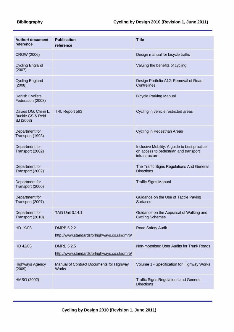
Bibliography Cycling by Design 2010 (Revision 1, June 2011)
Cycling by Design 2010 (Revision 1, June 2011)
Author/ document reference
Publication reference
Title
CROW (2006) Design manual for bicycle traffic
Cycling England (2007)
Valuing the benefits of cycling
Cycling England (2008)
Design Portfolio A12: Removal of Road Centrelines
Danish Cyclists Federation (2008)
Bicycle Parking Manual
Davies DG, Chinn L, Buckle GS & Reid SJ (2003)
TRL Report 583 Cycling in vehicle restricted areas
Department for Transport (1993)
Cycling in Pedestrian Areas
Department for Transport (2002)
Inclusive Mobility: A guide to best practice on access to pedestrian and transport infrastructure
Department for Transport (2002)
The Traffic Signs Regulations And General Directions
Department for Transport (2006)
Traffic Signs Manual
Department for Transport (2007)
Guidance on the Use of Tactile Paving Surfaces
Department for Transport (2010)
TAG Unit 3.14.1 Guidance on the Appraisal of Walking and Cycling Schemes
HD 19/03 DMRB 5.2.2
http://www.standardsforhighways.co.uk/dmrb/
Road Safety Audit
HD 42/05 DMRB 5.2.5
http://www.standardsforhighways.co.uk/dmrb/
Non-motorised User Audits for Trunk Roads
Highways Agency (2009)
Manual of Contract Documents for Highway Works
Volume 1 - Specification for Highway Works
HMSO (2002) Traffic Signs Regulations and General Directions

Cycling by Design 2010 (Revision 1, June 2011) Bibliography
Cycling by Design 2010 (Revision 1, June 2011)
Author/ document reference
Publication reference
Title
Institute of Highways and Transportation (1998)
Guidelines for Cycle Audit & Cycle Review
Jensen SU, Rosenkilde C, Jensen N (2007)
Road safety and perceived risk of cycle facilities in Copenhagen
Kelley, GA. (1995) South Med J 1995; 88: 42-46. Effects of Aerobic exercise in normotensive adults: a brief metaanalytic review of controlled clinical trials
Kennedy, JV & Hall RD (1997)
TRL Report 281 Accidents at urban mini-roundabouts
Land Transport Safety Authority, New Zealand (2004)
Bicycle Compatibility Index (BCI)
Land Transport Safety Authority, New Zealand (2005)
Cycle Network and Route Planning Guide
Leden, Gårdner, Pulkkinen (1998)
Measuring the safety effect of raised bicycle crossings
LTN 01/07 Department for Transport (1997) Traffic Calming
LTN 1/08 Department for Transport (2008) Traffic Management and Streetscape
LTN 1/86 Department for Transport (1986) Cyclists at Road Crossings and Junctions
LTN 1/95 Department for Transport (1995) The Assessment of Pedestrian Crossings
LTN 2/08 Department of Transport (2008) Cycle Infrastructure Design
LTN 2/09 Department for Transport (2009) Pedestrian Guardrailing
LTN 2/95 Department for Transport (1995) The Design of Pedestrian Crossings
Mersy, DJ. (1991) Postgrad Med 1991; 90: 103-7 and 110-2 Health benefits of aerobic exercise
NICHES (2006) New Seamless Mobility Services: Public Bicycles
Parkin, J and Meyers, C (2009)
Accident Analysis & Prevention 11th August 2009
The effect of cycle lanes on the proximity between motor traffic and cycle traffic
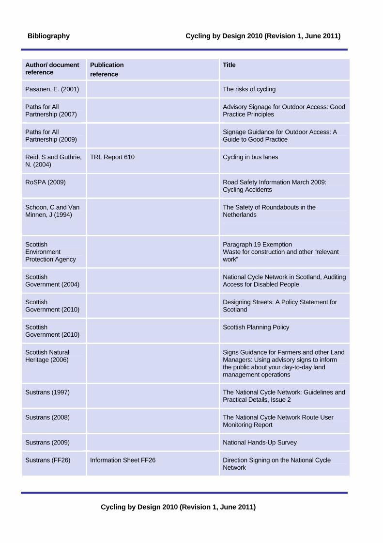
Bibliography Cycling by Design 2010 (Revision 1, June 2011)
Cycling by Design 2010 (Revision 1, June 2011)
Author/ document reference
Publication reference
Title
Pasanen, E. (2001) The risks of cycling
Paths for All Partnership (2007)
Advisory Signage for Outdoor Access: Good Practice Principles
Paths for All Partnership (2009)
Signage Guidance for Outdoor Access: A Guide to Good Practice
Reid, S and Guthrie, N. (2004)
TRL Report 610 Cycling in bus lanes
RoSPA (2009) Road Safety Information March 2009: Cycling Accidents
Schoon, C and Van Minnen, J (1994)
The Safety of Roundabouts in the Netherlands
Scottish Environment Protection Agency
Paragraph 19 Exemption Waste for construction and other “relevant work”
Scottish Government (2004)
National Cycle Network in Scotland, Auditing Access for Disabled People
Scottish Government (2010)
Designing Streets: A Policy Statement for Scotland
Scottish Government (2010)
Scottish Planning Policy
Scottish Natural Heritage (2006)
Signs Guidance for Farmers and other Land Managers: Using advisory signs to inform the public about your day-to-day land management operations
Sustrans (1997) The National Cycle Network: Guidelines and Practical Details, Issue 2
Sustrans (2008) The National Cycle Network Route User Monitoring Report
Sustrans (2009) National Hands-Up Survey
Sustrans (FF26) Information Sheet FF26 Direction Signing on the National Cycle Network

Cycling by Design 2010 (Revision 1, June 2011) Bibliography
Cycling by Design 2010 (Revision 1, June 2011)
Author/ document reference
Publication reference
Title
TA 57/87 DMRB 6.3.3
http://www.standardsforhighways.co.uk/dmrb/
Specification for Cattle Grids on Private Roads
TA 81/99 DMRB 6.3.4
http://www.standardsforhighways.co.uk/dmrb/
Coloured Surfacing in Road Layout (Excluding Traffic Calming)
TA 91/05 DMRB 5.2.4
http://www.standardsforhighways.co.uk/dmrb/
Provision for Non-Motorised Users
TAL 01/97 Department for Transport (1997) Cyclists at Road Narrowings
TAL 4/98 Department for Transport (1998) Toucan Crossing Development
TAL 7/98 Department for Transport (1998) Summary of Cycle Audit and Review
TAL 9/93 Department for Transport (1993) Cycling in Pedestrian Areas
TAL 9/97 Department for Transport (1997) Cyclists at roundabouts: continental design geometry
TD 16/07 DMRB 6.2.3
http://www.standardsforhighways.co.uk/dmrb/
Geometric Design of Roundabouts
TD 36/93 DMRB 6.3.1
http://www.standardsforhighways.co.uk/dmrb/
Subways for Pedestrians and Pedal Cyclists: Layout and Dimensions
TD 42/95 DMRB 6.2.6
http://www.standardsforhighways.co.uk/dmrb/
The Geometric Design of Major/ Minor Priority Junctions
TD 70/08 DMRB 6.1.1
http://www.standardsforhighways.co.uk/dmrb/
Design of Wide Single 2+1 Roads
TD 90/05 DMRB 6.3.5
http://www.standardsforhighways.co.uk/dmrb/
The Geometric Design of Pedestrian, Cycle and Equestrian Routes
Transport for London (2005)
London Cycling Design Standards
Transport Research Laboratory (1997)
Accidents at Urban Mini-Roundabouts
Transport Research Laboratory (2001)
Deliverable D5: Cost-Benefit Analysis of Measures for Vulnerable Road Users

Bibliography Cycling by Design 2010 (Revision 1, June 2011)
Cycling by Design 2010 (Revision 1, June 2011)
Author/ document reference
Publication reference
Title
Transport Scotland (2006)
Cycle Paths in Upland Areas: Hill Sheep Containment Issues and Solutions
Transport Scotland (2008)
Scottish Transport Appraisal Guidance
Transport Scotland (2009)
Disability Discrimination Act: Good Practice Guide for Roads
UK Parliament (1995)
Disability Discrimination Act 1995
UK Parliament (2005)
Disability Discrimination Act 2005
Warren, J. (2008) Transform Scotland Trust Towards a. Healthier Economy: Why Investing in Sustainable Transport Makes Economic Sense
World Health Organisation (2008)
Health Economic Assessment Tool for Cycling

Cycling by Design 2010 (Revision 1, June 2011) Bibliography
Cycling by Design 2010 (Revision 1, June 2011)
Page intentionally left blank

Cycling by Design 2010 (Revision 1, June 2011)
Cycling by Design 2010 (Revision 1, June 2011)

© Crown copyright 2011
ISBN: 978-1-906006-68-6
£50.00
You may re-use this information (excluding logos) free of charge in any format or medium, under the terms of the Open Government Licence. To view this licence, visit http://www.nationalarchives.gov.uk/doc/open-government-licence/or e-mail: [email protected]
Where we have identified any third party copyright information you will need to obtain permission from the copyright holders concerned.
Any enquiries regarding this document should be sent to us at:
Transport Scotland Major Transport Infrastructure ProjectsStandards, Traffic and Economics BranchBuchanan House58 Port Dundas RoadGlasgowG4 0HF
This document is also available on our website at http://www.transportscotland.gov.uk