Embed Size (px)
Citation preview


Cyclic Performance of Moment Resisting Welded Connections with RBS
Built by Iranian Profiles
Parham Memarzadeh, Mohammad Davarpanah
Department of Civil Engineering, Najafabad Branch, Islamic Azad University,
Najafabad, Iran
ABSTRAST: Reduced Beam Section (RBS) connections have been developed in
order to provide a reliable and more ductile performance. Iranian National
Provisions (INP) in Part 10 prescribes recommendations for the design of RBS
members. However, the effectiveness of these recommendations for Iranian
profiles is dubious, due to limited Iranian research in this field. Numerical study
was performed on various RBS connections designed according to INP-10 in
order to evaluate the proposed values of geometrical characteristics of the RBS.
Finite element models of the RBS connections were analyzed under cyclic loading
and the results are compared with the expected results and also with those
obtained from the analysis of connections designed according to FEMA 350. The
study confirms the need for readjustment of the geometrical characteristics of the
RBS in order to apply to Iranian profiles.
1. Introduction
Since 1994 Northridge earthquake, a bulk of research have been performed to
replace better connections for new steel moment frame and to enrich poor moment
connections for exiting steel moment frames. The prior and post-Northridge
laboratory observations have also demonstrated the inherent disability of the
conventional moment connections to develop enough ductility (Engelhard et al.
1993).
Since the Northridge earthquake, a number of various studies have been carried
out in order to improve the seismic performance of the conventional welded
connections. One of the most promising ways to modify the behavior of the
conventional moment frame is to soften a portion of beam flanges near the column
face (Plumier 1997; Engelhard et al. 1998). The connection softening may be
accomplished by trimming circular selectors from the beam flanges near the
column. This solution known as reduced beam section (RBS) method, leads
plastic hinges toward the beam span away from column face, resulting in the
reduction of stress concentration at the interface of beam and column. However,
as the result of reducing beam section within a sensitive zone, the beam becomes
more prone to buckling. Previous testing on the RBS moment connections (EC 8
2005; Plumier 1994; Chen et al. 1997) highlighted the effectiveness of the new
approach in the post-Northridge design era. The reduced beam section (RBS),
allows controlled yielding of the beam by moving the plastic hinge region at the
beam – in a short distance from the column’s face – protecting the connection
from any type of failure. Various shapes cutouts are possible (constant, tapered or
radius cut) to reduce the cross sectional area. Extensive experimental and
analytical projects have been conducted demonstrating that the radius cut behaves
with the highest rotational capacity. Recommendations for the design and
detailing of the RBS member were prescribed in FEMA 350 (2000) and FEMA
351(2000) regarding the location and reduction rate of RBS, based on the local
performance of tested beam to column assemblies. Several researches were
investigating the influence of the RBS technique, most of them including US
profiles and type of connections (Adan and Reaveley 2004; Deylami and Moslehi
Tabar 2008; Moon et al. 2009).
Although the RBS technique is widely investigated in the US, there is poor
existing data using the Iranian National Provisions (INP 2014). INP profiles and
types of moment connection that are widely used in Iran are not investigated in the
same level. For this reason, the INP (2014) in Part 10 recommended RBS
geometrical parameters are in need of further research in order to be applied with
the appropriate level of reliability.
2. Comparison of presented parameters for reduced beam section between
FEMA 350 and INP
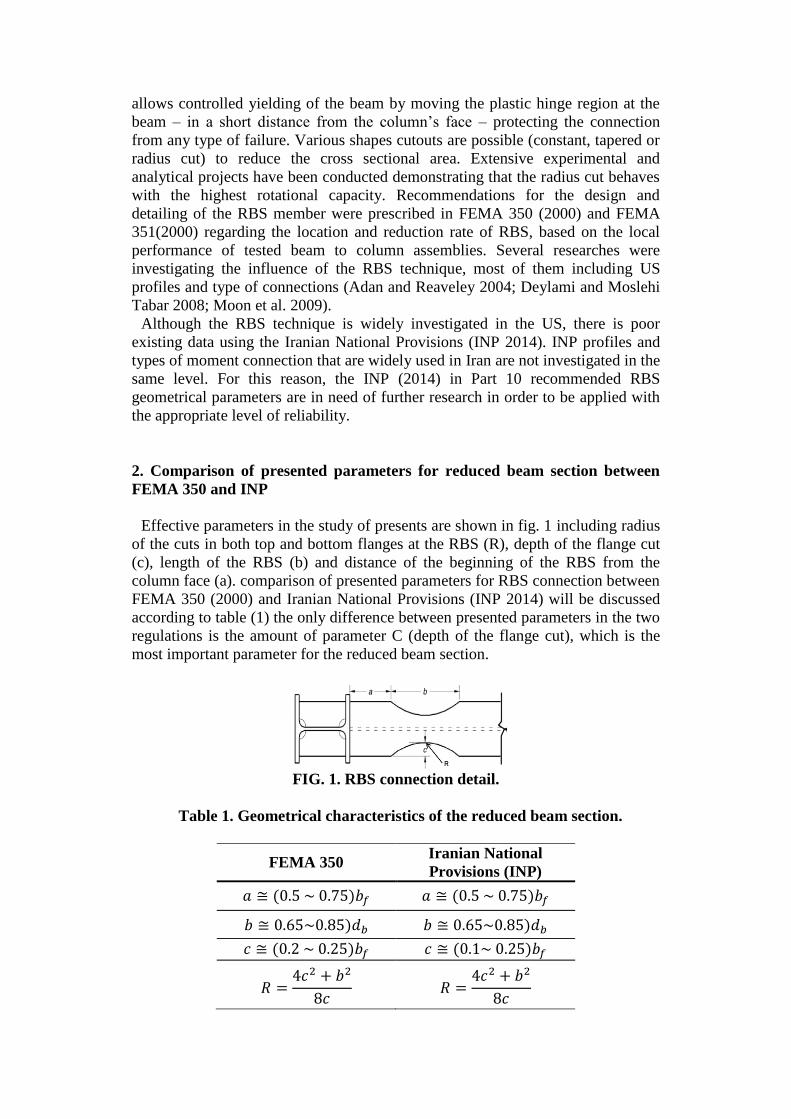
Effective parameters in the study of presents are shown in fig. 1 including radius
of the cuts in both top and bottom flanges at the RBS (R), depth of the flange cut
(c), length of the RBS (b) and distance of the beginning of the RBS from the
column face (a). comparison of presented parameters for RBS connection between
FEMA 350 (2000) and Iranian National Provisions (INP 2014) will be discussed
according to table (1) the only difference between presented parameters in the two
regulations is the amount of parameter C (depth of the flange cut), which is the
most important parameter for the reduced beam section.
FIG. 1. RBS connection detail.
Table 1. Geometrical characteristics of the reduced beam section.
FEMA 350 Iranian National
Provisions (INP)
𝑎 ≅ (0.5 ~ 0.75)𝑏𝑓 𝑎 ≅ (0.5 ~ 0.75)𝑏𝑓
𝑏 ≅ 0.65~0.85)𝑑𝑏 𝑏 ≅ 0.65~0.85)𝑑𝑏
𝑐 ≅ (0.2 ~ 0.25)𝑏𝑓 𝑐 ≅ (0.1~ 0.25)𝑏𝑓
𝑅 =4𝑐2 + 𝑏2
8𝑐 𝑅 =
4𝑐2 + 𝑏2
8𝑐

3. Design of specimens
To design a RBS connection with radius cut the recommended relations between
FEMA350 and Iranian National Provisions used.
Design steps are:
Step 1: Determine the length and location of the beam flange reduction, based on
the following:
𝑎 ≅ (0.5 ~ 0.75)𝑏𝑓 (1)
𝑏 ≅ 0.65~0.85)𝑑𝑏 (2)
Where a and b are as shown in Figure 1, and bf and db are the beam flange width
and depth respectively.
Step 2: Determine the depth of the flange reduction, c, according to the following:
I) Assuming the amount of parameter (c) being at minimum according to
FEMA350 (2000) and INP (2014):
According to FEMA 350
𝑐 = 0.2𝑏𝑓 (3)
According to INP (2014)
𝑐 = 0.1𝑏𝑓 (4)
II) Calculating ZRBS:
𝑍𝑅𝐵𝑆 = 𝑍𝑏 − 2 × 𝑐 × 𝑡𝑓 × (𝑑𝑏 − 𝑡𝑓) (5)
III) Calculating MF:
𝑀𝑓 = 𝑀𝑝𝑟 + 𝑉𝑝 × (𝑆ℎ −𝑑𝑐
2) (6)
IV) If 𝑀𝑓 < 𝐶𝑝𝑟 × 𝑅𝑦 × 𝑍𝑟𝑏𝑠 × 𝐹𝑦 the design is acceptable. If Mf is greater than
the limit, increase, c. The value of c should not exceed 0.25 bf.
Hence, the analysis for the finite element parametric study considering 6 models,
are summarized in Table 2. The material properties for the beams was obtained
from three- point bending coupon tests performed for this study. The resulting
values were as follows: Young's modulus E = 210000 𝑁
𝑚𝑚2 , yield stress f𝑦 =
240 𝑁
𝑚𝑚2 and ultimate stress f𝑢 = 370 𝑁
𝑚𝑚2 .

Table 2. General specifications of the models
Models Beam Column
Reduce parameters
(mm)
Designed according
to
a b c FEMA 350 INP
ORC1 IPE300 IPB300 - - - - -
RBS1 IPE300 IPB300 0.5bf 0.65db 0.2bf *
RBS2 IPE300 IPB300 0.5bf 0.65db 0.1bf *
ORC2 IPE360 IPB400 - - - - -
RBS3 IPE360 IPB400 0.625bf 0.75db 0.2bf *
RBS4 IPE360 IPB400 0.625bf 0.75db 0.1bf *
4. Finite element modelling
In the present project, the finite element package ABAQUS (1997) was used to
predict the structural behavior of RBS moment connections subjected to cyclic
loading The subassemblies were modelled using four node thin shell elements
with reduced integration (element S4R in ABAQUS). Fig. 2 shows a typical finite
element meshing used in this study. As observed in Fig. 2 a more refined mesh
was applied at the regions near the RBS. The cyclic displacement amplitude
followed the loading protocol in the AISC Seismic Provisions (AISC 2002),
which is the same as the SAC loading protocol 1997 (SAC 1997). The loading
protocol is shown in Fig. 3.
FIG. 2. View of the finite element mesh of the RBS connection
FIG. 3. Loading protocol [14]

5. Finite elements modeling results validation by experimental model
To verify the analytical models, we modeled the conventional connection tested
by Pachoumis and colleagues (2010) shown in Fig. 4, there is a close agreement
between the experimental results obtained by Pachoumis and colleagues and our
numerical results.
(a)
(b)
FIG. 4. Comparison between the experimental and numerical hysteretic
results, (a) experimental sample, (b) finite elements sample of the current
study
6. Description of model analysis
6.1 Stress distribution
The Von Misses stress distributions for 0.05 rad inter story drift angle are shown
in Fig. 5 for all models. It can be seen that concentrated stress for RBS models
designed according to FEMA 350 (2000) occurs in beams, for RBS models
designed according to Iranian National Provisions (INP, 2014) and ordinary rigid
connection (ORC) occurs in connection.

a b c
d e f
Fig. 5. Von Misses distribution (a) ORC1, (b) RBS1, (c) RBS2, (d) ORC2, (e)
RBS3, (f) RBS4.
6.2. PEEQ
The PEEQ index is defined as the plastic equivalent strain (PEEQ) divided by
the yield strain 𝜀𝑦 of the beam material, which represents the local strain demand
[16]. The plastic equivalent strain is defined as:
𝑃𝐸𝐸𝑄 = √2
3𝜀𝑖𝑗𝜀𝑖𝑗 (7)
where εij is the component of plastic strain in the direction specified by i and j.
The plastic equivalent strain (PEEQ) distributions for 0.05 rad inter story drift
angle are shown in Fig. 6 for all models. It can be seen that concentrated strain for
all types of RBS models occurs in beams and for ordinary rigid connection
(ORC), it occurs in connection. Also models designed according to FEMA 350
(2000) showed more appropriate behavior compared with those designed
according to Iranian National Provisions.

a b c
d e f
FIG.6. PEEQ index (a) ORC1, (b) RBS1, (c) RBS2, (d) ORC2, (e) RBS3, (f)
RBS4
To access the effect of the parameters on the ductile fracture potential of the
models of the various connection configurations, the Rupture Index (RI) was
computed from the finite element analysis results. The RI is defined as the ratio of
the equivalent plastic strain (PEEQ) index to the ductile fracture strain εf ,
multiplied by the material constant a i.e.
𝑅𝐼 = 𝛼𝑃𝐸𝐸𝑄
𝜀𝑦⁄
𝜀𝑓= 𝛼
𝑃𝐸𝐸𝑄𝜀𝑦
⁄
𝑒𝑥𝑝(1.5 𝑝
𝑞)
(7)
Where p and q are equal to the hydrostatic pressure and Von Misses stress,
respectively, with:
𝑃 = −1
3 𝜎𝑖𝑗 (8)

𝑞 = √3
2 𝑆𝑖𝑗𝑆𝑖𝑗 (9)
Values of the RI were used to evaluate and compare the potential for ductile
fracture of different locations in a finite element model or between two different
models at the same location. Research by Hancock and Makenzie (1976) has
shown that this criterion for evaluating the potential for ductile fracture to be
accurate. Fig. 7 indicates that the reduced beam section connection (RBS) has a
lower RI, and thus fracture potential, compared to ordinary rigid connection
(ORC) to a similar condition. The cause for the higher value of the RI in the ORC
connection is due to the larger plastic strains that develop in the connection region
near the column face. As it can be seen in Fig. 9 the RBS1 and RBS3 designed
according to FEMA 350 has minimum value of RI to compare with other
connection.
FIG.7. Effect of connection type on Rupture Index
6.3. Cyclic behavior
Moment-plastic rotation hysteretic responses of all models are shown in Fig. 8.
The moment was measured at the column face and the total beam rotation was
computed by dividing the total beam tip displacement by the distance to the
column face.
As it can be observed, all models have suitable hysteretic behavior. Hysteretic
curves show that the strength of the connection is reduced due to beam local
buckling. However, this strength degradation is not so important, since after the
buckling, the strength of connection in all models is still more than plastic
moment capacity of beams. Therefore, this connection can be classified as a full
strength connection. As it can be observed from the hysteretic curves, all models
have reached to 0.04 rad rotation, and the strength of connection at 0.04 rad
rotation is more than 80% of the beam plastic moment capacity, (0.8 Mp).
Consequently, this connection satisfies the criteria of AISC Seismic Provisions
(2005) for special moment frame systems.

a b c
d e f
FIG.8. Hysteresis response of beam (a) ORC1, (b) RBS1, (c) RBS2, (d)
ORC2, (e) RBS3, (f) RBS4.
6.4 Connection stiffness classification
The connections could be classified using moment-joint rotation curves. The
joint rotation is considered as the summation of connection rotation and panel
zone rotation.
Secant stiffness is computed using moment-joint rotation curves of models.
Secant stiffness is defined as:
𝐾𝑠 = 𝑀𝑆 𝜃𝑆⁄ (10)
𝑀𝑆 = 𝐹𝑦 × 𝑆 (11)
where Fy is the yield stress of steel, and S is beam section modulus.
𝜃S = joint rotation corresponding to MS obtained from moment-joint rotation
curves.
According to AISC (2005) Specifications for Structural Steel Buildings, if
KL/EI > 20 the connections can be considered as fully restrained. Where, L and
EI are length and bending rigidity of the beam respectively. Values of secant
stiffness and KL/EI are presented in Table 3 for all models. The value of L in this
table is considered as equal to the length of beam in the frame between two
columns which is twice the beam length in each side of column in selected
subassemblies.

As it can be seen in Table 3, all models are full restrained connection and also
Secant stiffness magnitude in RBS1 and RBS3 connections designed according to
FEMA 350 is bigger than that in other connections.
Table 3. Stiffness classification of connections.
Models MS
(kN.m)
𝜽𝑺
(Rad)
Ks
(kN.m) I (m4) L(m) KsL/EI
ORC1 133 0.00144 92.361 83.6e-6 5 26.31
RBS1 86 0.00123 69.918 53.4e-6 5 31.17
RBS2 114 0.00128 89.062 72.1e-6 5 29.45
ORC2 216 0.00146 147.945 162.7e-6 5 21.65
RBS3 174 0.00126 138.095 109.8e-6 5 30.72
RBS4 213 0.00131 162.595 135.1e-6 5 28.65
7. Conclusions
In this paper, the results obtained from modeling by ABAQUS computer
program were provided:
(1) In the RBS connection designed according to FEMA 350 (2000), plastic
deformations take place significantly in the beam.
(2) As shown in hysteretic curves, this connection is a full strength connection.
(3) This connection can be used in special moment frame (SMF) systems.
(4) All values of KL/EI are greater than 20; therefore, this type of connection is a
fully restrained connection.
(5) Specimens RBS1 and RBS3, which were not designed according to designed
according to Iranian National Provisions, exhibited excellent performance when
subjected to cyclic loading. The key parameters for the design of an RBS with
radius cut that were adopted by INP (2014) in part 10 should be readjusted in
order to be more safely applicable to Iranian profiles.
8. References
Adan, S.M. and Reaveley, L.D. (2004). "The reduced beam section moment
connection without continuity plates". World Conference on Earthquake No. 13,
Vancouver, Canada.
ABAQUS/PRE. User’s manual. Hibbit, Karlsson and Sorensen Inc.; (1997).
AISC. (2005). Seismic provision for structural steel building. American Institute
of Steel Construction, Chicago, Illinois.
Chen, S.J., Chu, J.M. and Chou, Z.L. (1997). "Dynamic behavior of steel frames
with beam flanges shaved around connection". Journal of Constructional Steel
Research, No. 42(1):49–70.
Deylamy, A., Moslehi Tabar, A. (2008). "Experimental study on the key issues
affecting cyclic behavior of reduced beam section moment connections". World
Conference on Earthquake Engineering, No. 13, Beijing, China.
Engelhardt, M.D. and Husain, A.S. (1993). "Cyclic-loading performance of
welded flange-bolted web connection". Journal of Structural Engineering, No.
119.

Engelhardt, M.D., Winnebeger, T., Zekany, A.J. and Potyaraj, T.J. (1996). "The
dog bone connection: part 2". Modern Steel Constructions.
EC 8, Part 3. (2005). Design of structures for earthquake resistance. Assessment
and retrofitting of buildings. EN 1998–3.
FEMA 350. (2000). Recommended Seismic Design Criteria for New Steel
Moment-Frame Buildings, Prepared by SAC connection Venture for the Federal
Emergency Management Agency. Washington, D.C.
FEMA 351. (2000). Recommended seismic evaluation and upgrade criteria for
existing welded steel moment frame buildings. Washington, D.C.
Hancock, J.W. and Mackenzie, A.C. (1976). "On the mechanisms of ductile
failure in high-strength steels subjected to multi-axial stress-states". Journal of the
Mechanics and Physics of Solids, No. 24, 147–69.
INP. (2014). Iranian National Provisions in Part 10, designing and constructing
steel structures.
Moon, K.H., Kim, B-Ch., Hwang, S.H. and Han, S.W. (2009). "Seismic
performance evaluation of the steel moment frames with reduced beam section
connections with bolted webs". International Symposium on Steel Structures No.
5 Seoul, Korea.
Pachoumis, D.T., Galoussis, E.G., Kalfas, C.N. and Christitsas, A.D., (2010).
"Reduced beam section moment connections subjected to cyclic loading:
Experimental analysis and FEM simulation", Journal of constructional steel
research, Elsevier, No. 31, 216-223.
Roeder, C.W. (2000). Connection performance state of art report. Report No.
FEMA-335, Washington, DC.
SAC. (1997). Protocol for fabrication, inspection, testing, and documentation of
beam-column connection tests and other experimental specimens, No. SAC/BD-
97-02, Version 1.1.
AISC. (2005). Seismic provision for structural steel building. American Institute
of Steel Construction, Chicago, Illinois.