Embed Size (px)
Citation preview
Abstract—Cyclic loading tests for four hybrid coupled shear walls
with various reinforcement details were performed. The primary
variables were reinforcement details of the coupled shear walls. As a
result, structural performances of the coupled shear walls were
dependent on the reinforcement details. The vertical reinforcements
have influence on the shear strength of the shear walls. The required
vertical reinforcement ratio in an embedded length was also proposed
by using the shear strength models of proposed PC coupled shear walls.
Design method of the precast concrete (PC) coupled shear wall was
proposed by assuming the distribution of compressive stress acting on
the flange of the embedded steel beam in the shear walls.
Keywords—Design method, coupled shear walls, reinforcement
detail, shear strength.
I. INTRODUCTION
OUPLING beams are responsible for the energy dissipation
capacity for the lateral force acting on the structure, and
have to be designed to exhibit a proper strength, rigidity and
deformability. According to Paulay’s researches [1], when shear
stress is '0.5 cf MPa or more, diagonal reinforcements should
be installed at reinforced concrete (RC) coupling beams.
However, there is a difficulty to install the diagonal
reinforcements to the RC coupling beams. For these reasons,
hybrid steel coupling beams have been proposed to improve the
constructability and to replace the conventional reinforced
concrete coupling beam by many researchers [2]-[8].
The experimental researches for hybrid steel coupling beams
were performed by Harries et al. [2],[3], Marcakis et al. [4],
Mattock et al. [5], Shahrooz et al. [6], and Kent et al. [7].
According to previous researches, it is required to inhibit the
premature failure of the coupled shear walls by special
reinforcement details. Existing design codes, especially ACI
318-11 [8], have provided reinforcement details for the special
structural walls and coupling beam at Section 21.9 in Chapter
21. However, specific design method of hybrid steel coupling
beam have not provided in those codes. Englekirk [9] has
suggested that the coupled shear walls should be reinforced by
additional reinforcements in around the embedded steel beam.
Woo-Young Lim is a post-doctoral researcher in the Department of
Architecture & Architectural Engineering at Seoul National University, Korea
(corresponding author’s phone: +82-10-7288-7902; e-mail:
Sung-Gul Hong is a professor in the Department of Architecture &
Architectural Engineering at Seoul National University, Korea (e-mail:
Structural performances such as strength, stiffness, and energy
dissipation capacity of the hybrid steel coupling beam are
greater than those of the RC coupling beams. Despite these
many advantages, it is difficult to apply the steel coupling beam
to conventional RC shear walls owing to the weak
constructability. If the coupled shear walls produced in
factories, the PC coupled shear walls are likely to be damaged in
the transport processes. Existing hybrid steel coupling beam
systems have a problem with using in the coupled PC shear
walls owing to the constructability. Thus, it is necessary to
improve the new hybrid steel coupling beam systems and also to
provide the special design method for the PC coupled shear
walls. In this study, Design method for coupled PC shear walls
was proposed based on the experimental studies.
II. TEST PROGRAM
A. Test specimens
Cyclic loading tests for the four coupled PC shear walls with
steel coupling beam were performed to evaluate the shear
strength and energy dissipation capacity. The main parameters
of the test were reinforcement details of the PC shear walls.
Figure 1 shows the reinforcement details of the test
specimens. The coupled PC shear walls had a dimension of 300
× 1500 × 1800 mm (11.8 × 59.1 × 70.9 in.). Four D19 (db = 19
mm or 0.75 in.) horizontal and vertical reinforcements were
installed to inhibit the concrete failure during the test at the
specimen’s boundary. Here, db is diameter of bars. SD400
(Korean Standard, fy = 400 MPa or 58 ksi) reinforcements were
used in each specimen. Design compressive strength of concrete
fc’ is 35 MPa (5.1 ksi).
P600ANC is a prototype test specimen designed by according
to ACI 318 design codes [8]. (see Fig. 1(a)) Ten D13 (db = 13
mm or 0.5 in.) and four D19 reinforcements for horizontal
reinforcement and ten D13 for vertical reinforcements were
provided in this specimen. Horizontal and vertical
reinforcement ratios were ρh = 0.005 and ρv = 0.0054,
respectively. H600ANC is the specimen that reinforced the
length as much as the embedded length by horizontal closed
hoops. The length of those bars is consistent with the length of
embedded steel beam. Details of the reinforcements of this
specimen are very similar to prototype test specimen P600ANC
as shown in Fig. 1(b). Since eight D16 (db = 16 mm or 0.62 in.)
horizontal reinforcements were provided, the horizontal
reinforcement ratio of this specimen is ρh = 0.0064. Sh600ANC
Cyclic Loading Tests for Hybrid Coupled Shear
Wall with Various Reinforcement Details
Woo-Young Lim, and Sung-Gul Hong
C
International Conference Data Mining, Civil and Mechanical Engineering (ICDMCME’2015) Feb. 1-2, 2015 Bali (Indonesia)
http://dx.doi.org/10.15242/IIE.E0215034 86

is the test specimen reinforced by the vertical reinforcements to
the entire length of the wall as shown in Fig. 1(c). Forty D13 ties
with 600 mm (23.6 in.) of length were provided at each 60 mm
(2.4 in.) of spacing. Horizontal and vertical reinforcement ratios
are ρh = 0.005 and ρv = 0.0054, respectively. SP600ANC is the
proposed test specimen, which was reinforced by three D16
closed ties in the embedded length at each 200 mm (7.9 in.) of
spacing, two D22 (db = 22 mm or 0.9 in.) and D19 horizontal
reinforcements, and four D22 diagonal reinforcements as
described in Fig. 1(d). Length of the closed ties which are
installed in embedment length is 620 mm (24.4 in.). Horizontal
and vertical reinforcement ratios are ρh = 0.01 and ρv = 0.0098,
respectively.
1500
400
800
1500
400
305
737
1800
300
300
D13@200
D13@270
φ60
D19
600
D13
D13300250250 310 310
Seat angle
D16
D13
D19
D19
B
B
A A
A-A section
B-B section
1500
400
800
1500
400
305
737
1800
300
285 265
D13@200
D13@270
φ60
600
D19
D13
2852657070240 240
Seat angle
D16
D13
D19
D19
D16
B
B
A A
A-A section
B-B section
1500
400
800
1500
400
305
737
1800
300
D13@200
D13@270D13
φ60
600
D19
D13
D13@60
Seat angle
D16
D13
D19
D19
B
B
A A
A-A section
B-B section
1500
400
800
1500
400
305
737
1800
300
225 225100 310 310100225 225
D19@200
D19@270
φ60
D22
600
Seat angle
D22
D19
D22
D22
D19
D16
A A
B
B
A-A section
B-B section
(a) (b)
(c) (d)
Fig. 1 Details of the test specimens: (a) P600ANC; (b) Sh600ANC; (c)
H600ANC; and (d) SP600ANC
Steel coupling beams were designed in accordance with AISC
design codes [10] as shear dominated members. Overall length
of the steel coupling beam including the steel plate shear
connection is 720 mm. The dimension of the steel coupling
beam is 175 × 400 × 11 × 5 mm (6.9 × 15.7 × 0.4 × 0.2 in.). Steel
plate connection had the length of 120 mm (4.7 in.) and
thickness of 20 mm (0.8 in.), respectively. Total length of the
steel coupling beam is 900 mm (35.4 in.) and the distance from
the surface of the PC shear wall to the loading point is 595 mm
(23.4 in.).
The length of the embedded beam (le) was 600 mm (23.6 in.),
which was obtained from the existing shear strength models as
shown in Table 1. Dimensions of the I-shaped beam were 175 ×
400 × 11 × 7 mm (6.9 × 15.7 × 0.4 × 0.3 in.). To minimize the
excessive deformation in the embedded steel beams, Four
stiffeners were installed at both side of the embedded beam in
distance of 200 mm. Top and seat angles were set up to induce
the shear deformation of the steel coupling beam. Steel coupling
beam and top-seat angels were assembled by using four
high-tensile bolts, which diameter (db) are 24 mm (0.94 in.).
The yield and tensile strength of D13, D16, D19
reinforcements used in the PC coupled shear walls were D13: fy
(D13)= 462 MPa (67.0 ksi), fu (D13)= 594 MPa (86.1 ksi), D16: fy
(D16)= 417 MPa (60.5 ksi), fu (D13)= 667 MPa (96.7 ksi), and D19
fy (D19)= 425 MPa (61.6 ksi), fu (D19) = 630 MPa (91.4 ksi),
respectively. The strength obtained from the material tests was
fc’ = 38 MPa (5.5 ksi). Design yield strength of the steel
coupling beam was Fy = 300 MPa (43.5 ksi).
B. Test set-up
Figure 2(a) shows test set-up. Test specimens were loaded at
the distance of 720 mm (28.3 in.) from the surface of the PC
shear wall until the ultimate failure by displacement control.
Figure 2(b) shows the loading schedule. Rotation angle was
incremented by 0.25 % from 0.25 % (1.5 mm or 0.06 in.) up to
2.0 % (12.0 mm or 0.47 in.) and after that was increased by 0.5
% from 2.0 % (12.0 mm or 0.47 in.) up to ultimate failure.
LVDTs were used to measure lateral and vertical displacement
of the test specimens. Numbers 1 for horizontal displacement
measurements at the top of the steel coupling beam (LV1), and
Number 2 and 3 for vertical displacement of the coupling beam
(LV2 and LV3), and Number 4 and 5 for vertical displacement
of the embedded steel beam (LV4 and LV5), and Number 6 and
7 for shear distortion of the PC shear wall (LV6 and LV7), and
Number 8 and 9 for lateral displacement at lower part of the
steel coupling beam and top – seat angles (LV8 and LV9), and
Number 10 for slip of the coupled PC shear walls (LV10),
respectively.
-6
-4
-2
0
2
4
6
0 6 12 18 24 30 36 42 48 54 60 66 72 78 84
Drif
t ra
tio (
%)
Number of cycles
LV1
LV8
LV9
LV10
LV4 LV5
LV3LV2
2,000kN Actuator
1800
1500
400
2637
(a) (b)
Fig. 2 Test set-up and loading schedule
III. TEST RESULTS
A. Load-rotation angle relationship
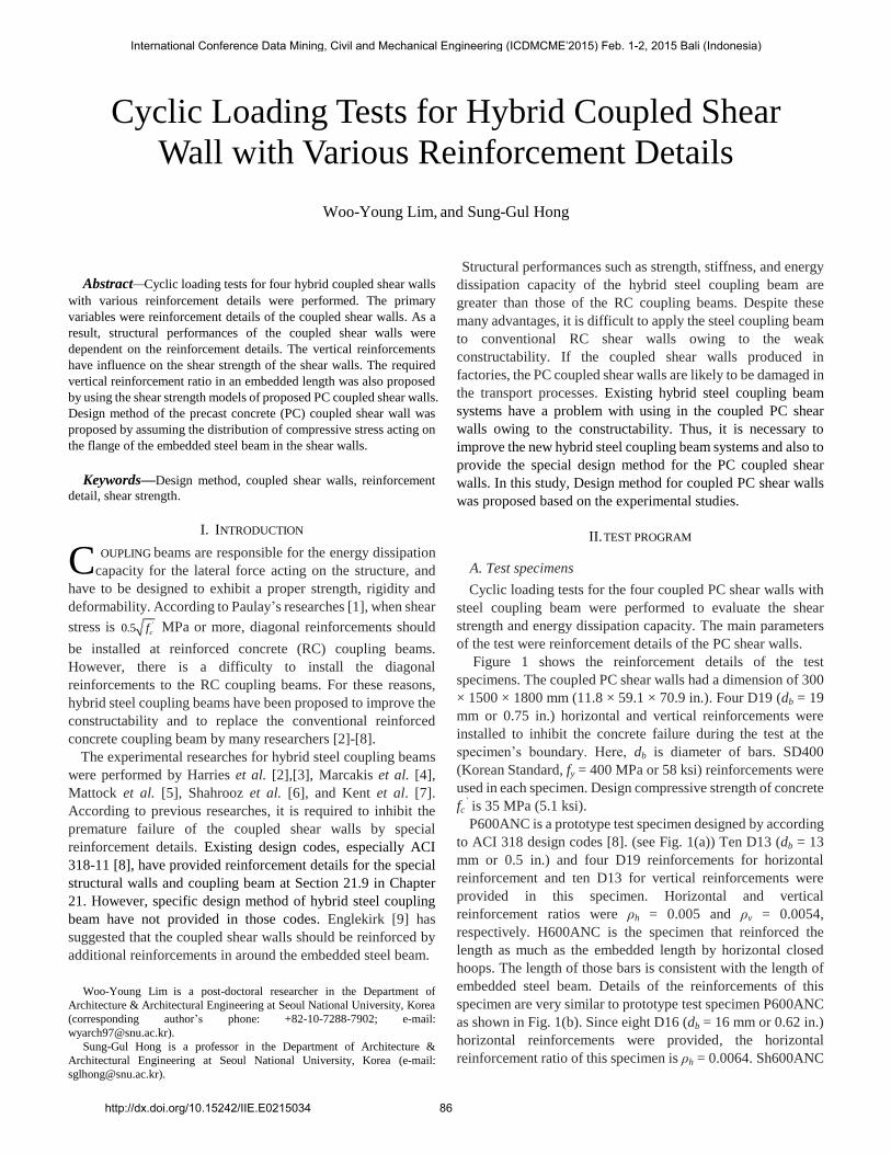
Figure 3 shows the load – rotation angle relationship of the
test specimens subjected to cyclic loading. The rotation angle is
the lateral displacement divided by the effective distance (720
mm) of the steel coupling beam. The terms of Vp represent the
plastic shear strength of the steel coupling beam for positive and
negative loading, respectively. The yield strength Vy and
displacement δy were defined as the point when the strain of the
steel coupling beam has reached the yield strain. The
displacement at the maximum strength represented by δmax and
ultimate displacement δu are also presented in Fig. 3.
International Conference Data Mining, Civil and Mechanical Engineering (ICDMCME’2015) Feb. 1-2, 2015 Bali (Indonesia)
http://dx.doi.org/10.15242/IIE.E0215034 87
The ratio of the maximum strength to the plastic shear
strength (Vmax/Vp) showed that P600ANC: 0.98, H600ANC:
1.19, Sh600ANC: 1.18, and SP600ANC: 1.18. The strength of
the prototype test specimen P600ANC did not reach the plastic
strength. On the other hand, the maximum strength of the other
specimens were exceeded the plastic shear strength.
-500
-400
-300
-200
-100
0
100
200
300
400
500
-8 -6 -4 -2 0 2 4 6 8
Lo
ad
(k
N)
Rotation angle (%)
u
pV
pV u
-500
-400
-300
-200
-100
0
100
200
300
400
500
-8 -6 -4 -2 0 2 4 6 8
Lo
ad
(k
N)
Rotation angle (%)
pV
pV
max
u
u
max
-500
-400
-300
-200
-100
0
100
200
300
400
500
-8 -6 -4 -2 0 2 4 6 8
Lo
ad
(k
N)
Rotation angle (%)
pV
pV
u
u
max
max
-500
-400
-300
-200
-100
0
100
200
300
400
500
-8 -6 -4 -2 0 2 4 6 8
Lo
ad
(k
N)
Rotation angle (%)
pV
pV
max
u
max
u
(a) P600ANC (b) Sh600ANC
(c) H600ANC (d) SP600ANC
Fig. 3 Load-rotation angle relationship: (a) P600ANC; (b)
Sh600ANC; (c) H600ANC; and (d) SP600ANC
B. Failure mode
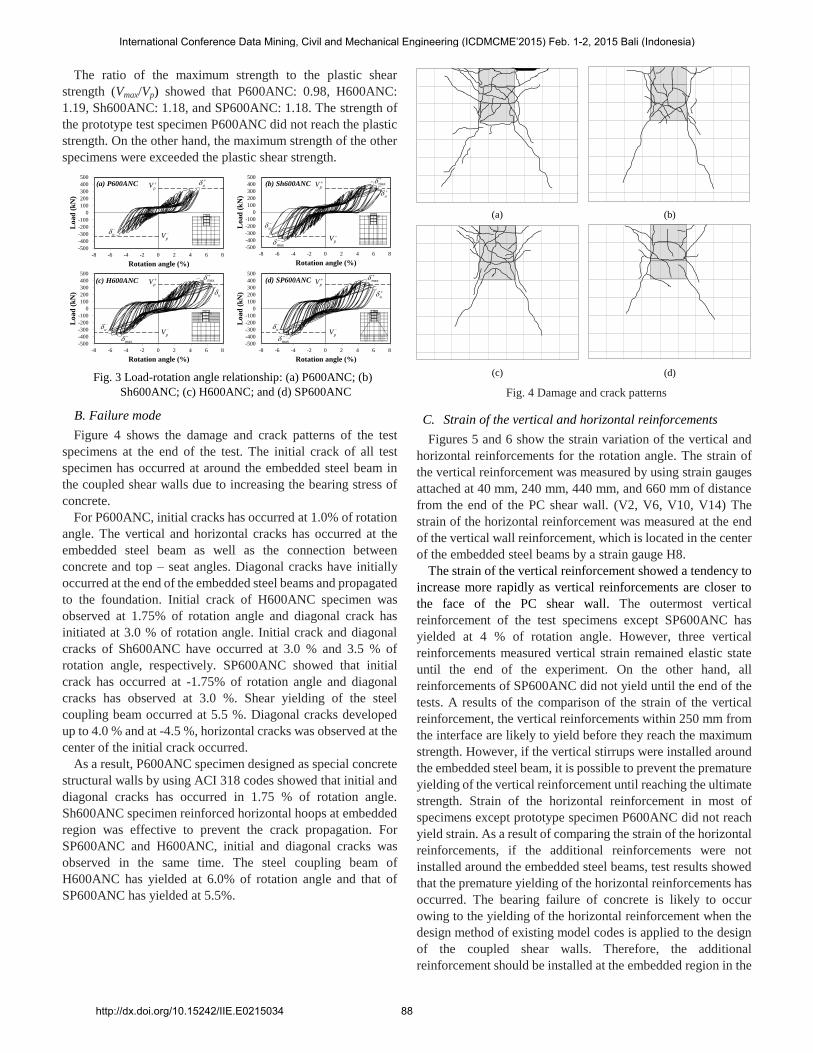
Figure 4 shows the damage and crack patterns of the test
specimens at the end of the test. The initial crack of all test
specimen has occurred at around the embedded steel beam in
the coupled shear walls due to increasing the bearing stress of
concrete.
For P600ANC, initial cracks has occurred at 1.0% of rotation
angle. The vertical and horizontal cracks has occurred at the
embedded steel beam as well as the connection between
concrete and top – seat angles. Diagonal cracks have initially
occurred at the end of the embedded steel beams and propagated
to the foundation. Initial crack of H600ANC specimen was
observed at 1.75% of rotation angle and diagonal crack has
initiated at 3.0 % of rotation angle. Initial crack and diagonal
cracks of Sh600ANC have occurred at 3.0 % and 3.5 % of
rotation angle, respectively. SP600ANC showed that initial
crack has occurred at -1.75% of rotation angle and diagonal
cracks has observed at 3.0 %. Shear yielding of the steel
coupling beam occurred at 5.5 %. Diagonal cracks developed
up to 4.0 % and at -4.5 %, horizontal cracks was observed at the
center of the initial crack occurred.
As a result, P600ANC specimen designed as special concrete
structural walls by using ACI 318 codes showed that initial and
diagonal cracks has occurred in 1.75 % of rotation angle.
Sh600ANC specimen reinforced horizontal hoops at embedded
region was effective to prevent the crack propagation. For
SP600ANC and H600ANC, initial and diagonal cracks was
observed in the same time. The steel coupling beam of
H600ANC has yielded at 6.0% of rotation angle and that of
SP600ANC has yielded at 5.5%.
(a) (b)
(c) (d)
Fig. 4 Damage and crack patterns
C. Strain of the vertical and horizontal reinforcements
Figures 5 and 6 show the strain variation of the vertical and
horizontal reinforcements for the rotation angle. The strain of
the vertical reinforcement was measured by using strain gauges
attached at 40 mm, 240 mm, 440 mm, and 660 mm of distance
from the end of the PC shear wall. (V2, V6, V10, V14) The
strain of the horizontal reinforcement was measured at the end
of the vertical wall reinforcement, which is located in the center
of the embedded steel beams by a strain gauge H8.
The strain of the vertical reinforcement showed a tendency to
increase more rapidly as vertical reinforcements are closer to
the face of the PC shear wall. The outermost vertical
reinforcement of the test specimens except SP600ANC has
yielded at 4 % of rotation angle. However, three vertical
reinforcements measured vertical strain remained elastic state
until the end of the experiment. On the other hand, all
reinforcements of SP600ANC did not yield until the end of the
tests. A results of the comparison of the strain of the vertical
reinforcement, the vertical reinforcements within 250 mm from
the interface are likely to yield before they reach the maximum
strength. However, if the vertical stirrups were installed around
the embedded steel beam, it is possible to prevent the premature
yielding of the vertical reinforcement until reaching the ultimate
strength. Strain of the horizontal reinforcement in most of
specimens except prototype specimen P600ANC did not reach
yield strain. As a result of comparing the strain of the horizontal
reinforcements, if the additional reinforcements were not
installed around the embedded steel beams, test results showed
that the premature yielding of the horizontal reinforcements has
occurred. The bearing failure of concrete is likely to occur
owing to the yielding of the horizontal reinforcement when the
design method of existing model codes is applied to the design
of the coupled shear walls. Therefore, the additional
reinforcement should be installed at the embedded region in the
International Conference Data Mining, Civil and Mechanical Engineering (ICDMCME’2015) Feb. 1-2, 2015 Bali (Indonesia)
http://dx.doi.org/10.15242/IIE.E0215034 88

coupled shear wall. In addition, it is necessary to revise the
existing shear wall design equation for the special concrete
structural walls.
0
0.001
0.002
0.003
0.004
Str
ain
(m
m/m
m)
Distance from face of the wall
51mm 251mm 451mm 651mm
1%
2%3%4%
V2
V6
V10
V14
(V2) (V6) (V10) (V14)
0
0.001
0.002
0.003
0.004
Str
ain
(m
m/m
m)
Distance from face of the wall
51mm 251mm 451mm 651mm
1%
2%
3%
4%5%
V2
V6
V10
V14
(V2) (V6) (V10) (V14)
0
0.001
0.002
0.003
0.004
Str
ain
(m
m/m
m)
Distance from face of the wall
51mm 251mm 451mm 651mm
1%2%
3%4%
5%
V2
V6
V10
V14
(V2) (V6) (V10) (V14)
0.000
0.001
0.002
0.003
0.004
Str
ain
(m
m/m
m)
Distance from face of the wall
51mm 251mm 451mm 651mm
1%
2%
3%
4%
5%
V2
V6
V10
V14
(V2) (V6) (V10) (V14)
(a) (b)
(c) (d)
Fig. 5 Strain of vertical reinforcements
-500
-400
-300
-200
-100
0
100
200
300
400
500
-0.001 0 0.001 0.002 0.003
Lo
ad
(k
N)
Strain (mm/mm)
YieldingH8
H8
-500
-400
-300
-200
-100
0
100
200
300
400
500
-0.001 0 0.001 0.002 0.003
Lo
ad
(k
N)
Strain (mm/mm)
YieldingH8
H8
-500
-400
-300
-200
-100
0
100
200
300
400
500
-0.001 0 0.001 0.002 0.003
Lo
ad
(k
N)
Strain (mm/mm)
YieldingH8
H8
-500
-400
-300
-200
-100
0
100
200
300
400
500
-0.001 0 0.001 0.002 0.003
Lo
ad
(k
N)
Strain (mm/mm)
YieldingH8
H83.99%y
4.26%y
(a) (b)
(c) (d)
Fig. 6 Strain of horizontal reinforcements
D. Strain of the steel coupling beam
Figure 7 shows the strain variations of the steel coupling
beam. The strain of the steel coupling beam of the P600ANC
did not reach the yield strain until the end of the tests. On the
other hand, the steel coupling beam of the H600ANC,
Sh600ANC, and SP600ANC yielded at rotation angle of y =
6.2 %, 6.5 %, and 5.3 % for positive loading and at y = -5.9 %,
-6.0 %, and -4.7 % for negative loading, respectively. The
reason why the steel coupling beam of P600ANC, which is
designed in accordance with ACI 318 design codes, did not
yield is that the bearing failure of the shear walls occurred at
about 4 % of the rotation angle before the strain of the steel
coupling beam has reached the yield strain. On the other hand,
the steel coupling beams of the other test specimens reinforced
by additional vertical and horizontal reinforcements, especially
SP600ANC showed the plastic behavior after the maximum
strength.
-500
-400
-300
-200
-100
0
100
200
300
400
500
-0.005 0 0.005 0.01 0.015 0.02
Lo
ad
(k
N)
Strain (mm/mm)
yieldingBW5
-500
-400
-300
-200
-100
0
100
200
300
400
500
-0.005 0.000 0.005 0.010 0.015 0.020
Lo
ad
(k
N)
Strain (mm/mm)
6.2%y
5.9%y
BW5
-500
-400
-300
-200
-100
0
100
200
300
400
500
-0.005 0.000 0.005 0.010 0.015 0.020
Lo
ad
(k
N)
Strain (mm/mm)
4.7%y
5.3%y
BW5
-500
-400
-300
-200
-100
0
100
200
300
400
500
-0.005 0.000 0.005 0.010 0.015 0.020
Lo
ad
(k
N)
Strain (mm/mm)
6.5%y
6.0%y BW5
(a) (b)
(c) (d)
Fig. 7 Strain of the steel coupling beam
E. Energy dissipation capacity
Figure 8 shows the energy dissipation capacity in accordance
with the rotation angles. Figure 9(a) represents the energy
dissipation capacities per specific rotation angle and Fig. 9(b)
shows the cumulative energy dissipation capacities. Energy
dissipation capacity was defined as the area of the load –
rotation curves per rotation angle and that was obtained in the
third cycle of the target displacement.
The energy dissipation capacity of the proposed test specimen
SP600ANC showed the maximum value and appeared the
lowest value in P600ANC designed by ACI 318-08. As a result,
the energy dissipation capacity of the test specimens reinforced
by the horizontal or vertical reinforcements was greater than the
others as described in strain variation of the reinforcements. In
other words, energy dissipation capacity of the PC coupled
shear walls depends on the reinforcement details.
0
2000
4000
6000
8000
10000
12000
14000
16000
18000
20000
0.0 2.0 4.0 6.0 8.0
En
erg
y d
issi
pa
tion
(kN
mm
)
Rotation angle (%)
SP11
SP12
SP13
SP14
0
50000
100000
150000
200000
250000
300000
350000
0.0 2.0 4.0 6.0 8.0
CU
mu
lati
ve
ener
gy
dis
sip
ati
on
(k
Nm
m)
Rotation angle (%)
SP11
SP12
SP13
SP14
(a) (b)
Fig. 8 Energy dissipation capacity per rotation angle: (a) Energy
dissipation capacity; and (b) Cumulative energy dissipation
capacity
IV. DESIGN METHOD OF COUPLED SHEAR WALL
Figure 9 shows the proposed design model of the PC coupled
shear walls with steel coupling beam. Stress distribution of the
embedded steel beam was assumed to be rectangular stress
block based on the experimental results. When applied shear
force occurs at the steel coupling beam, compressive strength Cf
and bearing strength Cb act at αle (0 < α < 1) and (1-α)le of upper
and lower part of flange, respectively. Compressive strength of
concrete is assumed to be 0.85fc’. Thus, shear strength is
obtained by using equilibrium condition as follows:
'0.85 1 2f b c e efV C C f l b (1)
where '0.85f c e efC f l b , '0.85 1b c e efC f l b .
International Conference Data Mining, Civil and Mechanical Engineering (ICDMCME’2015) Feb. 1-2, 2015 Bali (Indonesia)
http://dx.doi.org/10.15242/IIE.E0215034 89

For shear dominant hybrid steel coupling beam, the
embedded length of the steel beam is obtained when the shear
strength V calculated by Eq. (1) is equal to plastic shear strength
Vp as given:
' 20.85 2 1/ 2e
c ef
Val
f b
(2)
where a is the distance from the face of the shear wall to loading
point.
By using Eqs. (1) and (2), α is obtained as follows:
22 / 2
4
X X X
X
(3)
where '/ 0.85p c efX V f b a .
Thus, the length (1-α)le occurring the bearing failure of
concrete is given:
22 / 2
1 14
e e
X X Xl l
X
(4)
The predicted shear strength was relatively good agreement
with the experimental data.
el a
V
1 el
0.85 ckf
el
0.85 ckf
Embedded
steel beam
Steel
coupling
beam
Seat angle
Coupled PC shear wall
Fig. 9 Proposed design model of the coupled PC shear wall
Required vertical reinforcements of the PC coupled shear
walls can be obtained by using the compressive forces at the
flange of the embedded steel beams. As a result, the predicted
bearing stress of the coupled shear walls is represented by Cb =
xCf. That is, the bearing force determined by the proposed
method is greater about 32% than the compressive force
occurring in the upper flange of the embedded steel beam. Thus,
the required amount of the vertical reinforcements can be
calculated as given: '0.85 c e ef
f
y
f l bA
f
(5)
'0.85 1c e ef
b
y
f l bA
f
(6)
where fy represents the yield strength of the vertical
reinforcement (in MPa).
The vertical reinforcement ratio is obtained as follows:
f b
sc
e w y
C C
l b f
(7)
V. CONCLUSIONS
In this study, cyclic loading tests for the hybrid PC coupled
shear walls with various reinforcement details were performed
in order to evaluate the structural performance. The results
obtained from the experimental study is as follows.
1) The structural performance of the hybrid steel coupling
beam showed the different depending on the reinforcement
details of the PC coupled shear walls. As a result of the tests,
bearing failure has occurred early at the face of the PC coupled
shear walls designed as special structural walls and coupling
beams by ACI 318 design provisions. Test results showed that
premature failure of the PC coupled shear walls has been
prevented by the stirrups reinforced in embedded length.
2) As a result of the measurements of the strain variation of the
reinforcement, it has been shown that the vertical
reinforcements of the coupled shear walls have more influenced
on the ultimate failure than the horizontal reinforcements.
Although the coupled shear walls were designed in accordance
with ACI design codes, the strain of the vertical reinforcements
in 250 mm from the wall face has reached the yield strain at
about 4 percent of rotation angle. It is necessary to improve the
design method of the special structural walls and coupling
beams presented to the ACI codes. The vertical reinforcements
should be installed additionally in the region of embedded
length.
3) Test results showed that energy dissipation capacity depends
on the details of the reinforcement details of the PC coupled
shear walls. Energy dissipation capacities of the proposed test
specimen reinforced by the stirrups around the embedded steel
beam (SP600ANC) were greater than those of the test specimen
designed in accordance with ACI codes (P600ANC).
4) Design method of the PC coupled shear walls was proposed
by assuming the distribution of compressive stress in the steel
flanges of the embedded steel beam. According to the proposed
design method, it is reasonable that the amount of the vertical
reinforcements as much as 4% of reinforcement ratio was
installed in the region of the embedded length.
ACKNOWLEDGMENT
This research was financially supported by the Ministry of
Construction and Transportation of Korea (03 R&D A07-06);
The authors are grateful to the authorities for their support.
REFERENCES
[1] Paulay, T., and Binney, J. R., ―Diagonally Reinforced Coupling Beams of
Shear Walls,‖ Special publication ACI, Vol. 42, Detroit, pp. 579∼589.
[2] Harries, K. A., Mitchell, D., Redwood, R. G. and, Cook, W, D., ―Seismic
Design of Coupling Beams – A Case for Mixed Construction,‖ Canadian
Journal of Civil engineering, Vol. 24, No. 3, 1997, pp. 448∼459.
[3] Harries, K. A., Seismic Design and Retrofit of Coupled Walls using
International Conference Data Mining, Civil and Mechanical Engineering (ICDMCME’2015) Feb. 1-2, 2015 Bali (Indonesia)
http://dx.doi.org/10.15242/IIE.E0215034 90

Structural Steel, Department of Civil and Applied Mechanics, McGill
University, Montreal, Canada, 1995.
[4] Marcakis, A. H. and Gaffar, G. H., ―Precast Concrete Connections with
Embedded Steel Member,‖ PCI Journal, Vol. 25, No. 4, July-August
1980, pp. 88∼116.
[5] Mattock, A. H and Gaffar, G. H., ―Strength of Embedded Steel Sections
as Brackets,‖ ACI Jounal Vol. 79 No. 9, March-April 1982, pp. 83∼93.
[6] Gong, B., and Shahrooz B. M., ―Steel-Concrete Composite Coupling
Beams – Behavior and Design,‖ Engineering Structures, 23, 2001, pp.
1480∼1490.
[7] Kent, D. C. and Park, R., ―Flexural Members with Confined Concrete,‖
Journal of Structural Division, ASCE, Vol. 97, ST 7, July 1971, pp.
1969∼1990.
[8] ACI 318-11, Building Code Requirements for Structural Concrete and
Commentary, ACI Committee 318, American Concrete Institute, 2008,
pp. 356∼364.
[9] Englekirk, R. E., Seismic Design of Reinforced and Precast Concrete
Buildings, John Wiley and Sons, 2003, pp. 296∼345.
[10] AISC, Manual of Steel Construction – Load and Resistance Factor
Design – Third Edition, AISC, Inc., Chicago, IL, 2002.
International Conference Data Mining, Civil and Mechanical Engineering (ICDMCME’2015) Feb. 1-2, 2015 Bali (Indonesia)
http://dx.doi.org/10.15242/IIE.E0215034 91