Embed Size (px)
Citation preview

Print Date: 5/02/2016 7:58:00 a.m. 1
Cyclists enjoying the Gibbston River Trail, Image courtesy Queenstown Trails Trust
Cycle Trail and Track Design
Standards & Specifications

Print Date: 5/02/2016 7:58:00 a.m. 2
Contents
Introduction 3
Overarching Goal 3
Purpose 3
Scope of this Guide 3
Overview of Trail and Track Design Standards – QLDC, NZCT/DOC, IMBA 4
Trail and Track Grading & User Groups 5
Trail and Track grading system comparison – NZCT, DOC, QLDC 6
Detailed Trail Grade Specifications 6
Grade 1 6
Grade 2 6
Grade 3 7
Cycle Trail Design Considerations 8
Step 1: Identify the User Group & Required Trail Grade 8
Step 2: Design Alignment 8
Desire Line 8
Hairpins and Switchbacks 9
Curves, Hills and Cross Fall 10
Design Approval by QLDC 10
Trail Construction & Completion 11
Trail Defects & Defects Period 11
Appendix A – Grade 2 Construction Specification 11
Appendix B – Typical Design Cross Sections 11
References 12
Prepared for QLDC by:

Print Date: 5/02/2016 7:58:00 a.m. 3
Introduction
The Queenstown Lakes District Council administers over 180km of cycle trails and tracks. These trails
and tracks are a valuable asset to the Lakes District and the purpose of this standard is to ensure
greater consistency and quality in the development of all new trails. For simplicity, trails (as called in
Wakatipu) and tracks (as called in Wanaka) will collectively be referred to as trails by this document.
The development of a cycle trail design standard is being driven by the increasing development of
cycle trails in the Queenstown Lakes District and in particular trails developed as part of private land
development projects as well as those created by volunteer organisations.
The Council has recently taken over ownership of numerous sections of cycle trail in both Wanaka
and Queenstown and many of these have been built with significant design and construction defects
which results in the ratepayer funding realignment and repair works. Council is looking to minimise
this cost and ensure better quality trails are developed in the future to be fit for purpose.
This standard is intended to guide cycle trail designers and developers to achieve consistently high
standards of cycle trail best suited to meet long term community needs (network connections and
latent demand) and minimise ongoing maintenance costs to Council, as the trail owner.
The guide has been developed to closely mirror the New Zealand Cycle Trail (NZCT) “Cycle Trail
Design Guide”, 2010 with minor changes to take into account changes in design and construction
that have arisen during the course of the National Cycle Trail projects. The changes are in maximum
gradients, surface finish and additional detail on trail geometry that was not dealt with by this
previous standard.
The NZCT guide implemented and widely publicised the 1-6 trail grading system used by the
mountain biking community. In terms of trails developed within the QLDC, these will be graded 1-3
with tracks graded 4-6 being purpose built mountain bike tracks and not cycle trails. Development of
mountain bike tracks is outside of the scope of this standard.
Additionally, the Department of Conservation (DOC) also have track design guides. These mainly
relate to walking track construction and are available on the DOC website. DOC has adopted the
NZCT grading system of rating trails as 1-6.
Overarching Goal of this Design standard and Construction Specification
To guide land developers and trail designers to achieve a high quality cycle trail specifically designed
and built to cater to the needs of the community(s) it connects and serves and that minimises future
maintenance costs to Council.
Scope of this Guide
The design and construction of Grade 1-3 cycle trails. The design and construction of ‘mountain bike’
tracks (Grades 4-6) is very well covered by the IMBA “Guide to Building Sweet Singletrack” 2004
design guide (Refer references section). DOC’s track design guides are best suited for the design of
walking tracks only.
The design and construction of trails suited to horses has not been considered as part of this guide.

Print Date: 5/02/2016 7:58:00 a.m. 4
Overview of Trail and Track Design Standards
QLDC
NZCT / DOC
“Cycle Trail Design Standards & Specifications” - 2015
Detailed guide to the design and construction of cycle trails
“Cycle Trail Design Guide” – Viastrada/MED 2010
DOC have adopted NZCT grading system
GRADE 1, 2 & 3 CYCLE TRAILS
IMBA
NZCT / DOC
“Guide to Building Sweet Single Track” IMBA 2004
Detailed industry best practice guide to the Design &
Construction of MTB specific tracks
GRADE 4, 5 & 6 MTB TRACKS
“Cycle Trail Design Guide” – Viastrada/MED 2010
This is a trail rating system but not really a design &
construction guide for Grades 4-6. DOC has
adopted NZCT grading system
DOC
“Track Construction & Maintenance Guidelines” DOC, 2006 &
SNZ Handbook HB8630: Outdoor Visitor Structures which is a
detailed guide to walking track design
WALKING TRACKS

Print Date: 5/02/2016 7:58:00 a.m. 5
Trail Grading & User Groups
The New Zealand Cycle Trail Project (NZCT) commissioned a design guide in 2010 as part of the
nationwide cycle trail development project. Completed by Viastrada this guide is the best starting
point in the identification of a cycle trail grading system. (See Cycle Trail Design Guide 2010 –
Ministry for Economic Development)1.
Over the intervening 5 years we have refined this system and present the refined grading technical
specifications as follows:
I. Grade 1 – Easiest; gentle grades up to 2 degrees (1: 28) with short sections <100m up to 3
degrees, wide (2.5m+) and smooth trail ideal for all user groups. No fall hazards. These are
ideal for connecting communities and where families and novice cyclists are likely to be
present.
II. Grade 2 – Easy; Some gentle hills up to a maximum of 4 degrees (1: 14), wide (2-2.5m) with
some short (<50m) narrow sections of minimum width 1.5m, smooth surface with critical fall
hazards within 2m of track edge fully protected. These are ideal for connecting communities
and where families and novice cyclists are likely to be present but where Grade 1 gradients
cannot be achieved due to terrain constraints.
III. Grade 3 – Intermediate; gradients 0-4 degrees typically, more regular hills acceptable up to a
maximum 6 degrees (1: 10) where unavoidable terrain, width 1.2-1.5m and extended
narrower sections of minimum width 1.2m. Critical fall hazards at track edge protected only.
This is essentially an easy mountain bike track.
The majority of trails within the QLDC network are classed as Grade 1-2 with a few being Grade 3.
Table 1 gives a breakdown of the various grades for existing local trails.
In order to provide the greatest accessibility to any new trails, every trail should be designed to meet
Grade 1 or 2. Grade 3 should only be considered where the users are predominantly not commuters,
families or novice cyclists and the trail is not forming part of a connective network to link
communities or part thereof. In other words, not a critical linkage to the cycling network.
Comparison with NZCT/DOC Grading System
DOC has adopted the now widely used Kennet Brothers/NZCT trail grading system using numbers 1
to 6 to classify trails according to trail difficulty. Below is a brief overview of the difference to this
standard
NZCT Grade 1 – Same except grades not allowed to be steep if ridden in one direction only.
NZCT Grade 2 – Allows maximum grade of 6 degrees (leading developers to use this as a default
grade), allows surface roughness like roots and rocks (not suited to rider group), topcourse
aggregate of 30mm particle size (too course for good surface finish – Max 20mm)
NZCT Grade 3 – Allows grades up to 5 degrees (too steep, likely to cause rutting) and maximum
grades of 9 degrees (too steep for most riders, ruts badly)
In summary this new standard responds to the desire of many trail developers to seek the shortest
and steepest line for their trails. Setting lower grade limits and including trail geometry and cross fall
1 http://www.nzcycletrail.com/about/resources

Print Date: 5/02/2016 7:58:00 a.m. 6
details in the design specification is aimed at reducing the most common trail defects noted in this
region.
Detailed Trail Grade Specifications
The minimum specifications for each trail grade can be expanded as follows:
Grade 1
• A minimum width of 2.5m allowing for side by side riding. This makes passing and overtaking
easy, and provides sufficient width for novice riders to feel secure. The minimum width may
be reduced to protect historic features, or for environmental or visual amenity reasons.
Width also caters for 4wd vehicle access for maintenance purposes.
• Maximum prolonged gradient of 2 degrees (1:28). Maximum gradient of 4 degrees (1: 14)
• Maximum out-slope cross fall of 3% for straight sections of track.
• Corners shall have a minimum inner radius of 6.0m and in-slope gradient or cross-fall of 6-
8% except hair pins which must not exceed Typical Detail Sheet R4030_E3_3 of 2.5m
• Minimum structure width of 2.0m clear. Clear means between the closest parts of the
barriers.
• A clearly sign posted, well defined trail from beginning to end so visitors can easily find their
way in both directions and during inclement weather
• A compacted, well bound smooth riding surface with suitable camber to provide a
pleasurable and easy riding experience. Riders should never feel they are going to slide off
the trail. Minimum compacted aggregate depth of 75mm
• All water courses to be culverted or bridged
• All areas of fall hazard (exposure) shall be protected with barriers that meet the building
code.
• No stiles are to be used. All fences are to be crossed using cattle stops/bollards
• Sight lines – a minimum of 15m clear sight distance is to be achieved around all corners
Grade 2
• A minimum width of 2.0m but generally 2.5m wide allowing for side by side riding. This
makes passing and overtaking easy, and provides sufficient width for novice riders to feel
secure. The minimum width may be reduced to protect historic features, or for
environmental or visual amenity reasons. Width also caters for 4wd vehicle access for
maintenance purposes.
• Maximum prolonged gradient of 4 degrees (1:14) but where length >100m it must be broken
with flat recovery sections 10m long minimum at 50-75m spacing’s. Maximum gradient of 6
degrees (1: 10) for no more than 30m without a flatter recovery section of equal or greater
length
• Maximum out-slope cross fall of 3% for straight sections of track.

Print Date: 5/02/2016 7:58:00 a.m. 7
• Corners shall have a minimum inner radius of 6.0m and in-slope gradient or cross-fall of
minimum 6-8% (to be suited to the trail geometry to ensure slip free riding at design speed)
except hair pins which must not exceed Typical Detail Sheet R4030_E3_3 of 2.0m
• Minimum structure width of 2.0m clear. Clear means between the closest parts of the
barriers.
• A clearly sign posted, well defined trail from beginning to end so visitors can easily find their
way in both directions and during inclement weather
• A compacted, well bound smooth riding surface with suitable camber to provide a
pleasurable and easy riding experience. Riders should never feel they are going to slide off
the trail. Minimum compacted aggregate depth of 75mm
• All water courses to be culverted or bridged
• Areas of significant fall hazard shall be protected with barriers that meet the building code.
Areas of exposure where there is not a significant hazard may be protected with fencing,
bunding, vegetation or signage
• No stiles are to be used. All fences are to be crossed using cattle stops/bollards
• A minimum of 10m clear sight distance is to be achieved around corners, or additional
warning/speed calming measures may be required to avoid user conflict.
Grade 3
• A minimum width of 1.2m but generally 1.5m wide allowing for comfortable single file riding
only. The minimum width may be reduced to protect historic features, or for environmental
or visual amenity reasons over short (50m) sections. Width caters for quad bike access for
maintenance purposes.
• Maximum prolonged gradient of 6 degrees (1: 10) for sections not longer than 100m with
flat sections of minimum 25m length between. Maximum gradient of 9 degrees (1: 6) for no
more than 30m without a flat recovery section of equal or greater length
• Maximum out-slope cross fall of 3-6% for straight sections of track.
• Corners shall have a minimum inner radius of 3m and in-slope gradient or cross-fall of
minimum 8-15% (to be suited to the corner, speed and trail geometry) except hair pins
which must not exceed Typical Detail Sheet R4030_E3_3 of 1.2m
• Minimum structure width of 1.2m clear. Clear means between the closest parts of the
barriers to ensure quad bike access.
• A clearly sign posted, well defined trail from beginning to end so visitors can easily find their
way in both directions and during inclement weather
• A compacted riding surface of either insitu gravels or imported gravel to provide an all-
weather surface. Minimum depths to suit ground conditions
• Trail cross fall to provide an enjoyable riding experience for intermediate riders. Riders
should never feel they are going to slide off the trail due to incorrect cross slope.
• Water courses may be crossed with fords or be culverted or bridged if required. Any areas of
soft or boggy ground shall be made all weather to prevent mud and damage to the trail
surface

Print Date: 5/02/2016 7:58:00 a.m. 8
• Areas of significant fall hazard shall be protected with barriers that meet the building code.
Areas of exposure within 1m of the trail edge where there is not a significant fall hazard may
be protected with fencing, bunding, vegetation or signage
• Stiles may be used but preference should be given to using Cattle stops for convenience and
maintenance purposes. Where a stile is used a gate is required adjoining for maintenance
use.
• A minimum of 5m clear sight distance is to be achieved around corners, or additional speed
calming measures (trail alignment, sag, etc.) are required to avoid user conflict.
Cycle Trail Design Considerations
Step 1: Identify the User Group & Required Trail Grade
If the proposed trail is connecting communities and will form part of a larger network, then the
minimum standard will be Grade 2 (Always design to achieve the best grade where possible).
The user groups for Grades 1 and 2 are as follows:
a) Families including small children
b) Novice riders who either have never ridden or ride infrequently
c) Cycle tourers and commuters*
d) Mountain bike riders
e) Accessibility users
Groups (a) and (b) require a safe enjoyable cycling experience that is accessible with limited/no
cycling skill. The trail must be designed with the needs of the most discerning user group in mind.
For the above this would be families and novice riders. Cycle tourers, commuters and mountain
bikers have a higher degree of skill and experience making them able to handle less well formed
trails2.
Having identified the user group, the designer should aim to achieve the flattest grade possible to
meet the highest Grading. This ensures the maximum utility and accessibility to the community
irrespective of other aspects of the design.
Step 2: Design Alignment
The designer needs to consider how to fit the trail into the land to minimise gradients, minimise
hairpins, control storm runoff and drainage, climb hills, design and integrate structures and achieve
the required width and finish that creates or results in a desire line.
2 Commuter tracks require slightly different design considerations outside of the scope of this guide

Print Date: 5/02/2016 7:58:00 a.m. 9
Desire Line
The designer needs to understand where the trail users are coming from (How do they access the
trail) and going to (where will they leave the trail network) as well as how will the riders respond to
the trail alignment in order to understand the desire line. Desire line refers to the preferred
alignment for trail users and manifests itself in riders cutting corners or short cutting sections of trail
they consider ‘undesirable’ when it has not been achieved.
An example of an error in desire line is making curves across a flat open section of terrain when a
straighter piece of trail would suffice. Riders are likely to cut corners in this situation. Each section of
trail should be considered from the rider’s perspective to ensure that desire line is achieved as much
as possible.
Ultimately desire line can be hard to predict. A designer needs to consider this especially in open
country where riders can see the destination.
Hair pins or Switchbacks
It is often necessary to use hair pins (corners of ~180 degrees) to negotiate steep terrain. The use of
hairpins needs very careful consideration to avoid rutting, erosion damage and safety issues for
novice or inexperienced riders.
Hairpins should be graded such that the longitudinal grade through the corner is no more than 2
degrees with the cross-fall sloped to the inside to match the speed of travel such that the corner at
the design speed feels safe and secure without sideways slipping.
Hairpin radius should be as wide a possible within the terrain constraints but not less than the
minimum specified in design drawing R4030_E3_3 attached in Appendix A.
The approach to a hairpin should provide enough sight distance for riders to slow down prior to the
corner without locking their brakes and skidding. This requires that the approach gradient is quite
flat (0-2 degrees) and the surface is well compacted. It is unacceptable to have a constant 4 degree
grade into and through a hairpin as the approach will rut causing operational and maintenance
issues. Designers may use a rolling-up grade dip (sag) to slow riders naturally prior to a corner. This
reduces the likelihood of skidding and loss of control through the corner.
Curves, hills and Cross-fall
In hilly terrain, curves should follow the terrain. Additionally the terrain should be used to assist
drainage with low points in gullies and higher points near ridges. This promotes drainage towards
gullies.
The trail surface cross-fall should reflect the terrain and trail geometry. Out sloped corners (very
dangerous) are to be avoided at all costs. When a corner is properly designed and built a rider feels
well connected to the trail through adequate cross-fall for the design speed and side friction. Refer

Print Date: 5/02/2016 7:58:00 a.m. 10
to the typical cross sections attached for guidance. There are no set rules, but the designer must
ensure that the completed trail rides without inducing side slip or fear in the target user group.
Geotechnical Assessment of Trails
At the initial scoping stage it is desirable to undertake a desktop assessment of available information
to pin point any possible areas of instability where a trail is proposed. This allows appropriate
planning and funding to be included at the design stage. Additionally the designer should walk the
trail alignment to confirm no obvious areas of instability
During the design stage known areas of instability should be addressed by specific design or
alignments. If avoidable, this is the preferred option. However, as most trails are built on public land
adjoining water ways, often the only option is to build over these areas.
As part of the following approval process, areas of instability should be clearly identified on the
design plans together with site assessment and solutions. Council wish to avoid ongoing
maintenance issues relating to instability in cycle trails and it is hoped such planning will reduce the
incidence.
Design Approval by QLDC
Prior to any works commencing on the site, the trail designer shall submit the trail design plan, long
section (if available – for large projects it is often not possible or cost effective to prepare detailed
terrain models), typical cross section, trail design user group and outline of how the trail caters to
the user group and fits the trail network together with construction specifications to QLDC for
approval prior to commencing any trail works on site.
Additionally the designer shall ensure the proposed trail is marked out on site with flagging tape at
no more than 20m intervals and staked in detail for hairpins and curves to ensure the proposed
alignment is able to be assessed in detail. The assessment will include a minimum of alignment and
gradient checks.
QLDC shall have the opportunity to inspect the trail alignment on site with the designer. Any
amendments requested by the Council shall be addressed to Council’s satisfaction prior to approval
of the works.
While the approval process is designed to identify errors in the design and layout of the trail, it is not
possible to anticipate every issue. Further, due to terrain constraints, vegetation cover and access, it
may not be possible to assess and design every section of trail in a cost effective manner. Therefore,
the design approval does not in itself reduce any liability on the trail developer to achieve the
standards and riding requirements detailed in earlier sections of this standard.

Print Date: 5/02/2016 7:58:00 a.m. 11
Trail Construction & Completion
At the completion of works, the trail contractor and developer shall certify the works as complete
and issue a completion certificate in the form of NZS 4404:2010 Schedules 1B & 1C. The Council shall
then inspect the works to confirm the completed trail meets the needs of the user
groups/community the trail serves. This shall include test riding the completed trail, measuring
grades and cross falls and corner radius. The completion inspection is not solely a compliance check
but a confirmation of achieving the needs of the trail user.
Where the trail is found to be deficient in terms of grades, alignment, cross fall or other defects (see
defects section), the trail developer shall remedy the defect prior to Council signing the s224c
certificate and/or taking over the trail asset. Alternatively the trail developer may enter into a cash
bond for the value of the works in accordance with Council’s bonding policy for land development
works.
For trails involving structures that do not require a building consent the trail developer shall submit
the following to Council:
• NZS 4404:2010 Schedule 1B (contractors completion)
• NZS 4404:2010 Schedule 1C certificate (Construction review)
• Typical design details for the structure
Where a structure requires a building consent, the trail developer shall supply Council’s Parks
Department a copy of the building consent documents including PS1, PS3, PS4 and Code Compliance
together with design drawings and/or as-built drawings prior to sign off/acceptance of the asset.
While this may be a double up on the BC process, often the design detail is not readily accessible and
the purpose is to ensure the Parks Department has a complete set of documents for ongoing
operation and maintenance.
Additionally all trails and structures including bridges, culverts, signs, bollards, cattle stops, fences
etc. shall be accurately surveyed and an as-built plan prepared and submitted in accordance with
Council’s land development standards to detail all trail related assets being taken over by Council.
The Defects Period
Once the works have been signed off by Council as complete, the trail developer shall be responsible
for a 12 month defects period. At the completion of the defects period, Council shall be advised and
a final inspection undertaken. The final inspection shall assess the trail as if it were in the new as-
built state. That is the trail developer shall be required to present the trail in an as-new condition at
the end of the defects period.
If the trail requires changes to alignment to avoid or remedy rutting, surface erosion or desire line
errors, the trail developer shall be responsible for such modifications at their cost prior to Council
taking over responsibility irrespective of whether these were noted at the time of the design

Print Date: 5/02/2016 7:58:00 a.m. 12
approval or completion inspection as often it takes time for errors in design and construction to
manifest through use of the trail.
The following parameters shall be achieved for completed trails at the end of the defects period:
• The trail shall have good flow and speed control that does not result in rutting or surface
erosion from skidding
• Finished surface shall be interlocking at the end of the defects period and free from loose
gravel.
• The surface of the gravel and +0.5m either side of the formation edge shall be clear of all
weeds. If there are weeds within the surface gravel, this shall be considered a defect and the
developer shall be liable to remedy by mechanical removal.
• Within all the earthworked areas adjoining the trail, all noxious weeds shall be removed
• All verges shall be mown/cut to a maximum 350mm height up to +0.5m off the edge of the
formation
• Any stormwater erosion shall be stabilised with rock protection or matting
• Adverse cross fall shall be rectified
• Any silting of culverts or debris in culverts or water tables shall be cleared
• Full design width shall be presented
• Vegetation shall be clear 1.0m beyond the edge of the trail and 2.5m above the trail
Trail Construction Specification – Grade 2
Attached as Appendix A is the standard Construction Specification for a Grade 2 Trail. The
specification outlines the standard work methodologies required to complete a cycle trail to Council
standards.
Where designers are forming a Grade 1 or Grade 3 trail, the specification shall be modified in
accordance with the section “Detailed Trail Grade Specifications” to take account of differing
maximum gradients, curve radius, surface and so forth.
Trail Construction – Typical Cross Sections & Details
Attached as Appendix B are typical cross section and detail plans ref R4030_E3_1-4. These provide
design detail in relation to typical cross sections in different terrain, use of curves and hairpins and
other typical details used in cycle trail construction but are not intended to cover every aspect of
trail construction.

Print Date: 5/02/2016 7:58:00 a.m. 13
References
• International Mountain Bicycling Association (IMBA) “Guide to Building Sweet Single Track”
• Standards New Zealand NZS HB 8630:2004 – Tracks and Outdoor Visitor Structures
• “Cycle Trail Design Guide” 2010 Viastrada/MED, prepared for the New Zealand Cycle Trail
Project
• QLDC Cycleway Maintenance Specifications c.2010
• Standards New Zealand NZS 4404:2004 – Land Development & Subdivision Engineering
• “Track Construction & Maintenance Guidelines” 2006, Department of Conservation
About the Author
Southern Land Ltd is a Wanaka based surveying, resource planning and land development
consultancy. Our cycle trail projects include the design & development of the Alps to Ocean,
Roxburgh Gorge and Clutha Gold Trails plus involvement in mountain bike parks, mountain bike
tracks and outdoor recreational facilities across Otago. Southern Land Ltd has recently completed a
feasibility study for trails linking Cromwell to Clyde and Wanaka to Cardrona. Southern Land Ltd was
a finalist in the IPENZ New Zealand Engineering Excellence Awards 2014 for the Clutha Gold Trail.

1 Status – For Approval Date – April 2015
08/09/2015 17:56:00
GRADE 2 - CYCLE TRAIL CONSTRUCTION
-TECHNICAL SPECIFICATION -
1.0 TRACK CONSTRUCTION
1.1 Track Alignment
1.1.1 The track alignment is marked on site with RED/WHITE flagging tape. Markers are generally spaced at 20-50m intervals.
1.1.2 The Contractor is responsible for setting out and constructing the track following these markers.
1.1.3 If the Contractor wishes to deviate the track formation more than two metres either side of the design line, specific approval shall be obtained from the Engineer for each and every deviation.
1.1.4 Deviation from the design line up to two metres either side may be made to avoid living trees, archaeological features, fallen logs, rocks or adverse ground conditions. Approval from the Engineer is not required in such instance.
1.1.5 The Contractor shall be responsible for ensuring the maximum track gradient requirements in this specification are not exceeded on the track. If the Contractor believes this cannot be achieved on the design line or within two metres of this then he shall advise the Engineer.
1.1.6 The constructed formation shall follow the most practical line to achieve the design grades and to create an enjoyable riding experience appropriate to a Grade 2 trail (See QLDC Cycle Trail Design Standards 2015).
1.2 Formation Earthworks, Width & Grade
1.2.1 All organic material shall be removed from the track formation area prior to commencing any formation earthworks. Where possible, leaf litter and top soil shall be retained adjacent to the track for spreading over exposed earthworks on completion of the formation.
1.2.2 Tree roots up to 100mm diameter shall be removed where necessary to enable formation excavation.
2 Status – For Approval Date – April 2015
08/09/2015 17:56:00
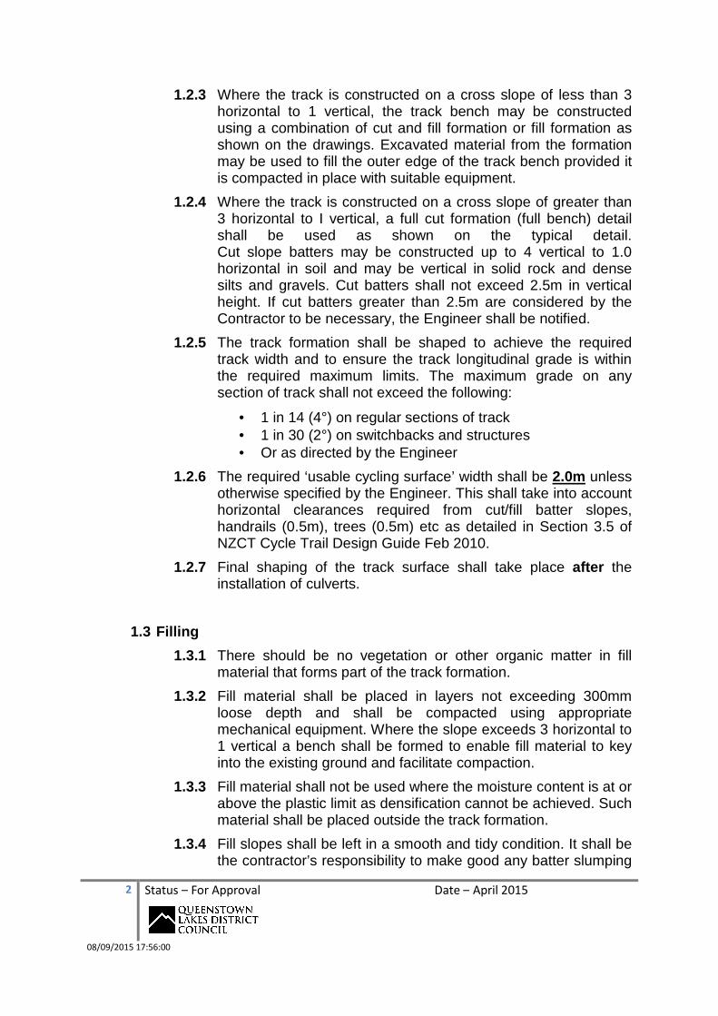
1.2.3 Where the track is constructed on a cross slope of less than 3 horizontal to 1 vertical, the track bench may be constructed using a combination of cut and fill formation or fill formation as shown on the drawings. Excavated material from the formation may be used to fill the outer edge of the track bench provided it is compacted in place with suitable equipment.
1.2.4 Where the track is constructed on a cross slope of greater than 3 horizontal to I vertical, a full cut formation (full bench) detail shall be used as shown on the typical detail. Cut slope batters may be constructed up to 4 vertical to 1.0 horizontal in soil and may be vertical in solid rock and dense silts and gravels. Cut batters shall not exceed 2.5m in vertical height. If cut batters greater than 2.5m are considered by the Contractor to be necessary, the Engineer shall be notified.
1.2.5 The track formation shall be shaped to achieve the required track width and to ensure the track longitudinal grade is within the required maximum limits. The maximum grade on any section of track shall not exceed the following:
• 1 in 14 (4°) on regular sections of track • 1 in 30 (2°) on switchbacks and structures • Or as directed by the Engineer
1.2.6 The required ‘usable cycling surface’ width shall be 2.0m unless otherwise specified by the Engineer. This shall take into account horizontal clearances required from cut/fill batter slopes, handrails (0.5m), trees (0.5m) etc as detailed in Section 3.5 of NZCT Cycle Trail Design Guide Feb 2010.
1.2.7 Final shaping of the track surface shall take place after the installation of culverts.
1.3 Filling
1.3.1 There should be no vegetation or other organic matter in fill material that forms part of the track formation.
1.3.2 Fill material shall be placed in layers not exceeding 300mm loose depth and shall be compacted using appropriate mechanical equipment. Where the slope exceeds 3 horizontal to 1 vertical a bench shall be formed to enable fill material to key into the existing ground and facilitate compaction.
1.3.3 Fill material shall not be used where the moisture content is at or above the plastic limit as densification cannot be achieved. Such material shall be placed outside the track formation.
1.3.4 Fill slopes shall be left in a smooth and tidy condition. It shall be the contractor’s responsibility to make good any batter slumping

3 Status – For Approval Date – April 2015
08/09/2015 17:56:00
or subsidence which occurs during the operation of this contract and including during the defects liability period.
1.3.5 Where fill is intended to be placed onto soft or swampy ground, the Engineer may advise the Contactor to lay geotextile material to separate the fill material. Geotextile shall be laid in accordance with manufacturers recommendations.
1.4 Track Drainage
1.4.1 Rolling grade dips (grade reversals) shall be formed in the track surface to divert surface water on sloping sections of track at ≤30m spacing’s where water tables are not installed. Grade reversals shall be 2-3m in length and be of a smooth profile to ensure a smooth ride for cyclists.
1.4.2 Water tables in accordance with the typical details shall be installed on each section of track formation prior to placing top course metal.
1.4.3 Water tables shall have a grade of >1% towards the discharge point (if any). A discharge point shall be provided anywhere there is a sag point in the track.
1.4.4 Water table discharge points shall be installed at the following spacing’s or as directed by the Engineer:
• 50m where the track grade is ≤ 1:20 (3°) • 15m where the track grade is between 1:10 and 1:20 (3°-6°)
1.4.5 Water table discharge shall consist of minimum 250mm smooth walled culvert under the track to direct water to lower ground on the down slope side of the track.
1.4.6 Culvert pipes shall be installed with a minimum 5% fall to the outlet and a minimum of 150mm cover to the finished track surface.
1.4.7 The inlet to culverts installed for the discharge of water tables shall have a 200mm x 200mm x 250mm minimum deep sump at the culvert inlet which has an invert level at least 100mm below the culvert pipe invert. A 300mm long stop bank shall be provided after the sump pit to force water into the pipe.
1.4.8 Culverts shall be of sufficient length to pass under the track and extend beyond any fill.
1.4.9 The outlets of culvert pipes shall discharge at ground level without a free fall from the end of the pipe. Where the outlet slope is on steep loose material, a rock apron shall be provided to prevent scour.

4 Status – For Approval Date – April 2015
08/09/2015 17:56:00
1.4.10 Culverts shall be smooth bore Farm Tough type coloured black of minimum 250mm internal diameter or similar as approved by the Engineer.
1.4.11 The inlet and outlet of culverts that discharge continuous water flows shall include local stone/mortar headwalls.
1.4.12 Where the culvert discharges only stormwater and the inlet or outlet may be subject to maintenance vehicle loads (that is they are within 300mm of the track edge), the headwalls shall be mortared.
1.4.13 For all other culverts where the inlets and outlets are not able to be driven on, headwalls are optional
1.4.14 Lintel rocks for headwalls shall have a minimum diameter (or long side) of not less than 2x culvert diameter for pipe sizes 250-500mm diameter.
1.5 Track Shaping
1.5.1 Prior to placement of track surfacing aggregate, the track sub-grade shall be shaped as follows
• Crowned surface having a maximum 3% fall to each side from the centreline for straight sections in flat country.
• Single slope formation with a 3% fall to the downhill side for straight sections in hilly country or where side drains are not provided.
• Single cross slope formation with a 5-10% fall to the inside of corners for winding sections.
• If after rain, water is left sitting or pooling on the surface, this will be considered a defect and require rectification by the contractor.
1.6 Pavement Surfacing
1.6.1 Prior to placement of track surfacing, the strength and density of the track sub-grade shall, wherever possible, be improved by the use of suitable compaction equipment such as vibrating rollers or plate compactors.
1.6.2 Suitable surfacing material shall be a crushed & well graded AP2O (or smaller) type aggregate having a maximum particle size of 20mm and be supplied from a weed free source. The stone particles shall be durable with at least 50% crushed faces. Rounded particle river gravels or beach gravels are not acceptable as a track surfacing aggregate

5 Status – For Approval Date – April 2015
08/09/2015 17:56:00
1.6.3 Ideally the track surfacing aggregate shall have a range of particle size distribution including between 5-8% by weight portion of clay content to facilitate binding the surface.
1.6.4 A sample of aggregate shall be provided to the Engineer for approval prior to placement.
1.6.5 The track surface layer shall have a minimum compacted depth of 75mm (equates to 100mm loose). This layer shall be placed and compacted in a single layer or where additional material is added after compaction the original layer shall be scarified prior to placement of the additional aggregate.
1.6.6 The aggregate shall be placed in such a way as to minimize segregation of the particle sizes. Shovels, beam rakes or excavator buckets should be used to move material if required.
1.6.7 The surface shall be shaped to achieve the required cross fall and longitudinal smoothness with a grader or similar machine. Grading with an excavator is not acceptable.
1.6.8 The aggregate surface shall be compacted after placement with a plate compactor or other vibrating equipment to achieve a well bound surface suitable for cycling. The cross fall of the finished track surface shall be as stated in Section 4.5.1.
1.6.9 To achieve optimum compaction, water shall be sprayed onto the aggregate surface. Compaction will be deemed complete when a well bound pavement surface is achieved which is free of voids and loose stone.
1.6.10 The completed track surface shall be free from loose stones (interlocking mosaic is required) and surface undulations to achieve a smooth & comfortable riding experience. Wavy or corrugated surfaces shall be deemed a defect and shall not be acceptable. The final test shall consist of riding a standard non-suspended bicycle along the completed surface to check for such defects.
1.7 Rock Excavation & Blasting
1.7.1 Areas requiring rock excavation are not necessarily shown on the design drawings.
1.7.2 Blasting of rock may be used where it is not practical to break or remove rock by mechanical means and achieve a solid level surface finish for the formation.
1.7.3 Any rocks that are too large to move whole shall be drilled and blasted.

6 Status – For Approval Date – April 2015
08/09/2015 17:56:00
1.7.4 All blasting shall be carried out in accordance with the Department of Labour Code of Practice for Construction Blasting Safety.
1.7.5 The Contractor shall provide the Engineer with at least 48 hours notice before blasting operations are to commence. The Ministry of Business Innovation & Enterprise shall be notified at least 24 hours prior to the blasting commencing.
2.0 HERITAGE & ENVIRONMENT
2.1 Archaeological Matters
2.1.1 If any archaeological evidence in the form of mining relics, stacked stone tailings, water races, sluicing, shell, bone, charcoal, greenstone, hangi stone, or artefact is uncovered during any construction, work must cease in that particular area and the Engineer must be notified immediately.
2.1.2 Work in the vicinity of sites where archaeological evidence is uncovered shall not re-commence until the Engineer gives approval. Delays due to unexpected finds may be a variation at the applicable rates.
2.1.3 The contractor shall implement all mitigation measures approved in any archaeological authority obtained from the Historic Places Trust relating to track works. If this is not practical, they shall advise the Engineer prior to any works covered by such Authority.
2.2 Vegetation
2.2.1 The survey line/design plans marked will identify all vegetation requiring removal. Mature trees will be affected in some areas due to legal access constraints but in general the track alignment should consider options around mature trees and any significant fauna.
2.2.2 Any tree exceeding 300mm diameter, that needs removal will be identified prior to the start of any works; any tree exceeding 300mm diameter must have the approval of the Engineer before it can be removed.
2.2.3 The completed track must have a cleared vegetation line of 2.5m vertical and a horizontal line of 1.0m either side of the track edge. All stumps created in the course of the construction are to be removed unless indicated by the engineer. All slash, branches and removed stumps must be removed from site or chipped or burned (note burning requires a permit from the TA).

7 Status – For Approval Date – April 2015
08/09/2015 17:56:00
2.3 Health & Safety
2.3.1 The Contractor shall at all times comply with the provisions of the Health and Safety in Employment Act 1992. The Contractor shall take all necessary steps to ensure that the obligations placed on the “Principal” and the “Person who controls the place of work” under the provisions of the Act are complied with at all times and shall immediately advise the Principal of any obligations not being fulfilled.
2.3.2 The Contractor shall prepare a Safety Plan, which shall identify all potential risks and hazards to all personnel on site. The plan shall include safety procedures, requirements for protective clothing and equipment, safety equipment, mitigation procedures, emergency procedures, emergency communications and any other requirements deemed necessary.
2.3.3 The Safety Plan shall be submitted to the Engineer by the Contractor who shall confirm that the Safety Plan has been implemented and is operating on the site.
2.3.4 If at any stage during the course of the works, the Engineer or the delegated representative(s) observe activities or procedures which do not comply with the Safety Plan, a ‘Stop Work’ notice may be issued to the Contractor.
2.3.5 Extensions of time arising out of ‘Stop Work’ notices issued to the Contractor due to non-compliance with the Safety Plan will not be considered.
2.3.6 The Contractor shall ensure that during the execution of the Contract there is no risk to the health and safety of other Contractors or employees of DOC, LINZ or Contact Energy, or to members of the public that may be in the vicinity of the site.
2.3.7 The Contractors’ Safety Plan shall include particular procedures with respect to maintaining the safety of users of the track during construction including use of appropriate signage, barriers and other protection deemed necessary.
2.3.8 The contractor shall use all practical means to prevent members of the public from using any structures until such time as a Code of Compliance Certificate has been issued for the structure.
2.4 Building Consent
2.4.1 The Contractor shall comply with all conditions of Building Consents relating to structures.

8 Status – For Approval Date – April 2015
08/09/2015 17:56:00
2.4.2 If inspections are required by the Council building inspectors, it shall be the Contractor’s responsibility to ensure that the Council is kept informed and given sufficient notice as to when inspections are needed.
2.4.3 The Principal shall obtain all building consents unless otherwise noted.
2.5 Resource Consent
2.5.1 The Contractor shall comply with all conditions of Resource Consents relating to track formation and structures.
2.5.2 If inspections or monitoring is required by either the QLDC or ORC it shall be the Contractor’s responsibility to ensure that the Council is kept informed and given sufficient notice as to when inspections are needed.
2.6 Producer Statements
2.6.1 The Contractor shall, on completion of the works, provide the Engineer with a Producer Statement-Construction (PS3) as setout in NZS 3910:2003 Schedule 6. The issuing of a Certificate of Practical Completion is subject to the receipt of the PS3.
2.7 Reinstatement of Area & Grassing
2.7.1 The Contractor and any Sub-constructors employed by the Contractor shall reinstate all land affected by the works, including the re-establishment of working areas, to a condition at least equal to that at the commencement of the works. Grass seed shall be spread on all areas of spoil where appropriate.
2.8 Materials brought onto Site
2.8.1 All aggregate brought onto the site for the purpose of track surfacing or any materials brought in as fill, are to be from a weed free source and are to be inspected and approved by the Engineer prior to delivery on site.
2.8.2 Materials are to be stockpiled in approved places and all remnants removed from the site on the completion of the project, except where the Engineer has approved surplus materials that may be left in stockpiles on the site.

9 Status – For Approval Date – April 2015
08/09/2015 17:56:00
2.9 Removal of Waste Material
2.9.1 All timber cut-offs, surplus materials and any waste is to be removed from the site at the completion of the work
2.9.2 Waste is defined as all foreign material on the site. This includes but is not limited to spilt concrete, nails, wood, plastic and metal off-cuts.
2.9.3 Waste or rubbish being held at the site prior to removal is to be stored in such a fashion that it cannot be blown about by the wind. No tyres are permitted.
2.9.4 Major repairs to machines are not permitted on site without approval of the Engineer.
2.10 Helicopter Operations
2.10.1 The Contractor shall obtain prior approval from the Engineer before each and every helicopter operation.
2.10.2 The Contractor is responsible for obtaining all required Civil Aviation and other permits necessary for helicopter operations.
2.10.3 The Contractors Safety Plan shall include procedures for such operations and the proposed measures to ensure public safety during the operations.
2.10.4 All materials dropped by a helicopter operator either by accident or on purpose outside of approved sites must be reported to the Engineer as soon as possible and any such materials shall be removed as soon as possible. Site restoration work must be carried out to the satisfaction of the Engineer in the event of any damage from dropped items.
3.0 TIMBER STRUCTURES
3.1 Relevant Standards
3.1.1 The underlying Standards relevant to this Section are:
NZS 3601 Metric Dimensions of Timber NZS 3602 Timber & Wood Based Products for use in Buildings NZS 3603 Timber Structures NZS 3604 Light Timber Framed Buildings NZS 3605 Timber Piles & Poles for use in Buildings NZS 3640 Timber Treatment Specifications NZS 1328 Glue Laminated Structural Timber

10 Status – For Approval Date – April 2015
08/09/2015 17:56:00
3.2 Scope & General
3.2.1 This section of the contract work shall consist of all carpentry including the associated jointing brackets, cleats, bolts, nails etc as shown on the drawings or specified herein or otherwise.
3.2.2 This includes, but is not exclusive to the construction of boardwalks, barriers and retaining walls.
3.2.3 All timber shall be sound, free from knots and well-seasoned and maintain figured dimensions.
3.2.4 All timber shall be rough sawn sizes unless specifically noted otherwise.
3.2.5 Timber shall comply with Table 1
3.3 Timber Treatment
3.3.1 Treatment shall be as noted in the table below. Treatment shall comply with the current requirements of the Timber Preservation Council. All treated timber shall be branded with the appropriate woodmark. It is preferred that timbers be treated at least 2 months prior to installation.
3.3.2 Cut faces of timber sections greater than 50mm thick shall be treated with Metalex or similar field applied preservative treatment.
Table 1: Timber Specification and Treatment
Structure & Application Species Grade Treatment
Round piles Pinus
Radiata. NZS 3605 H5
Retaining wall boards, Boardwalk end boards and bearers and other sawn timber in contact with the ground or within 150mm of the ground.
Pinus Radiata
G8 or VSG8
H5
Boardwalk joists, bracing, decking and blocking. Barrier balusters and rails
Pinus Radiata
G8 or VSG8
H3.2
Glulam Beams Pinus
Radiata GL10 H3.2

11 Status – For Approval Date – April 2015
08/09/2015 17:56:00
3.4 Fixtures & Fittings
3.4.1 Bolts and washers shall be hot dip galvanised engineers bolts of the diameters and sizes shown on the drawings unless specified otherwise.
3.4.2 Bolts may consist of hot dip galvanised or stainless steel threaded rod cut to length on site.
3.4.3 All hot dip galvanised rod cut ends shall be treated with ‘dry galv’ corrosion protection.
3.4.4 All galvanised bolts in contact with treated timber shall be protected using general purpose grease in pre-greased holes
3.4.5 Thread protrusion past the nut shall be a minimum of one thread pitch after tightening.
3.4.6 All nails shall be lOOmm x 4.Omm FH galvanised steel unless specified otherwise.
3.4.7 The contact faces of washers shall be coated with grease.
3.4.8 Washers shall be fitted to both ends of bolts and shall comply with the following minimum standards:
Bolt Size Washer (mm) M12 50 x 50 x 5.O M16 65 x 65 x 5.0
3.5 Protection Up To Installation
3.5.1 All materials shall be protected against physical damage.
3.6 Standards of Workmanship
3.6.1 All work shall be in accordance with industry best practice
3.6.2 Details not shown on the drawings shall be formed according to the principles of NZS 3604 or referred to the Engineer.
3.6.3 All work is to be accurately set out.
3.6.4 All structural members are to be fixed true to line.
3.7 Foundations & Concrete Work

12 Status – For Approval Date – April 2015
08/09/2015 17:56:00
3.7.1 All Concrete used for the embedment of posts or headwalls shall have a 20mm maximum aggregate size and be a mix designed to have a minimum 28 day compressive strength of 2OMPa.
3.7.2 All concrete shall comply with NZS 3104 or NZS 3108 including specification and techniques setout herein.
3.7.3 The contractor shall be responsible for locating any services on site. Any damage to underground services shall be repaired at the Contractors expense.
3.7.4 Excavations for foundations are to be built to the dimensions and details shown allowing for working room as required.
3.7.5 Where holes are dug or augured for foundations, the Contractor is responsible for ensuring the stability of the hole to ensure the hole maintains its required dimensions before pouring concrete. The costs of any stability work will be deemed to be included in the Contractors tender price.
3.8 Glue Laminated Structural Members
3.8.1 All beams shall comply with NZS 1328 GL10 grade.
3.8.2 Material for the members shall be Radiata Pine with a moisture content not exceeding 18%.
3.8.3 All members shall be made for Category 3: Exterior Exposed. The adhesive used shall be resorcinol glue.
3.8.4 End joints should be randomly spaced throughout the depth of a member to avoid concentration of joints.
3.8.5 Finish shall be ‘standard’ in accordance with NZS 3606 unless specified otherwise.
4.0 GABION PROTECTION
4.1 Installation
4.1.1 Gabion baskets unless otherwise specified shall be 2m long by 1m high and 1m wide and made from 2.7mm pvc coated wire.
4.1.2 Gabion baskets shall be installed in accordance with the manufacturers recommendations and industry best practice including appropriate backfill, inter-connections and tying and geotextile separation (filter cloth) to prevent backfill migration.
4.1.3 All areas requiring gabion wall installation shall be marked on site by the Engineer prior to installation and agreed with the contractor.

13 Status – For Approval Date – April 2015
08/09/2015 17:56:00
4.1.4 Where gabions are laid more than 1m in height, subsequent layers shall be offset 300mm.
5.0 TIMBER RETAINING WALLS
5.1 Installation
5.1.1 Timber retaining walls shall be installed in accordance with the design drawings to achieve minimum embedment depths, maximum heights and angles.
5.1.2 All timber retaining walls shall be fixed together with either galvanized bolts/washers or galvanized purlin screws. Nails shall not be used for fixing timbers.
5.1.3 All timbers shall comply with Section 3.3 Table 1 above
6.0 TIMBER CRIB WALLS
6.1 Installation
6.1.1 Crib walls shall be installed in accordance with the design drawings
6.1.2 All timber shall comply with Section 3.3 Table 1 above
6.1.3 Timber shall not be joined with nails. All timbers shall be either plated and bolted or plated and galv purlin screwed together to prevent breakage and splitting of timber.
6.1.4 The end and corners of such walls are to be protected with a minimum 100x50 timber running vertically to prevent end breakage.

14 Status – For Approval Date – April 2015
08/09/2015 17:56:00
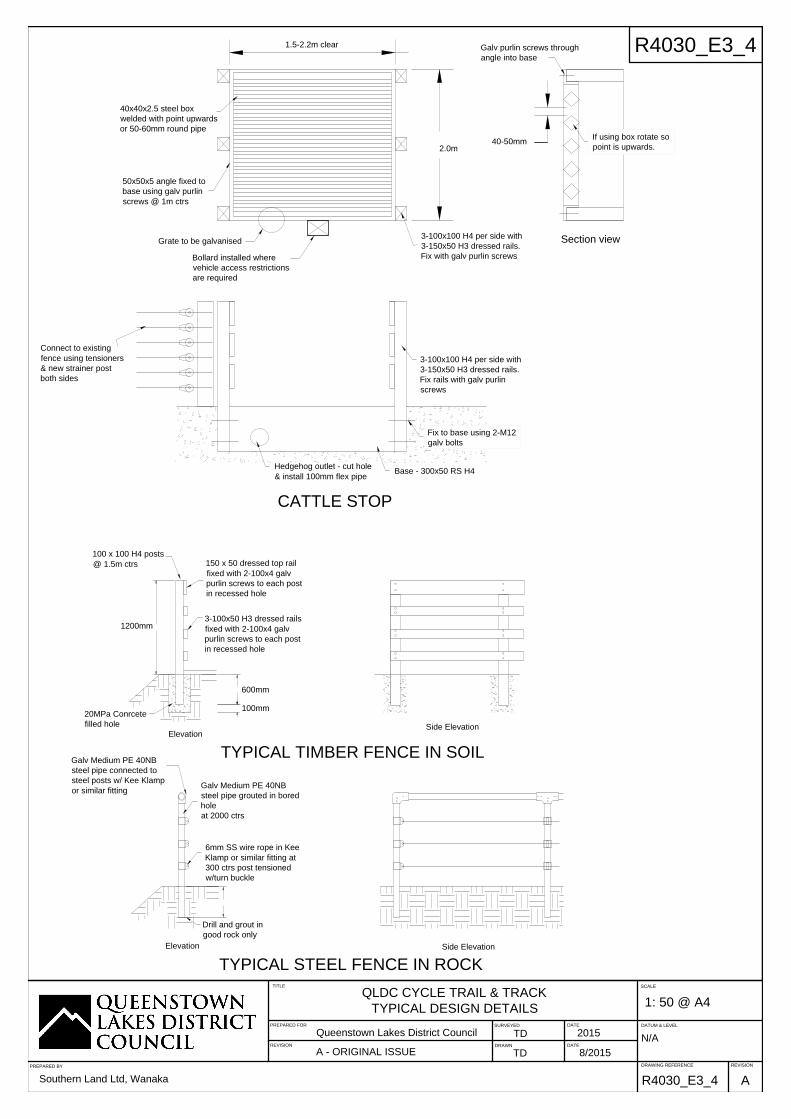
7.0 Cattle Stops & Bollards
7.1 Design & Installation
7.1.1 Cattle stops shall generally be as per the typical detail plan Sheet R4030_E3_4 The cattle stops shall have a minimum trafficable width as per the required minimum structure width for the trail Grade to enable maintenance access
7.1.2 Cattle stops shall have as a minimum a galvanized steel grate consisting of either rounds or flats sharp side up welded to a steel surround. Base and sides may be either timber or metal.
7.1.3 Cattle stops shall be installed at grade with the adjoining cycle trail and in line. Where restricting vehicle access is necessary, a timber bollard shall be installed in the centre of one approach and be of the lockable type.
7.1.4 A minimum 100mm flexible pipe shall be installed into the base of the cattle stop to enable hedgehogs to exit from the sump
7.1.5 Bollards for use on QLDC trails shall be as per attached typical detail plan R4030_E??? and shall be installed in accordance with this plan. Bollards can be sourced from Milburn Fencers Ltd

1
2
3
TYPICAL TRACK GEOMETRY
IN VARIED TERRAIN
GULLY
RIDGE
FLAT
1
0
0
1
0
5
1
1
0
C
e
n
t
r
e
l
i
n
e
G
r
a
d
e
CREST
SAG
SAG
Min 3% xfall
3
%
x
f
a
l
l
M
in
3
%
x
f
a
ll
3% xfall
M
in 3%
xfall
M
in 3%
xfall
CREST
Culvert for water table discharge
No water tables
2m either side of crest
Water tables in wet areas
only OR as directed by
the Engineer
Refer plan R4030_E3_2 for
typical cross sections
up
up
down
down
down
R
Minimum Corner
Radius R
Grade 1 = 6.0m
Grade 2 = 6.0m
Grade 3 = 3.0m
TRAIL SURFACING Grade 1 & 2
Minimum 75mm compacted AP20
type clay bound gravel
TITLE
REVISIONDRAWING REFERENCE
DATUM & LEVEL
SCALE
1: 50 @ A4
R4030_E3_1
N/A
PREPARED FORSURVEYED
DRAWN
DATE
DATE
Queenstown Lakes District Council
TD
TD 8/2015
2015
QLDC CYCLE TRAIL & TRACK
TYPICAL DESIGN DETAILS
REVISION
A - ORIGINAL ISSUE
A
R4030_E3_1
PREPARED BY
Southern Land Ltd, Wanaka

2
1
Max 3% fallMax 3% fall
Sloped water table profile
Min base 200mm wide.
Water tables not to be cut
vertical adjoining trail edge
2
1
Min 3% fall towards
inside of corners
Min 3% fall towards
inside of corner
Min. 250mm Dia. farm tuff or
similar where necessary to
discharge water tables or as
directed by the Engineer.
Minimum grade 1:20
1
Maximum fill slope
Finished trail surface
300mm beyond edge of
trail to culvert inlet/outlet
300
SINGLE CROSSFALL
1:50 USE IN FLAT COUNTRY
1
FULL CUT BENCH
1:50 USE WHERE CROSS SLOPE >3:1 (>18°)
2
CUT & FILL
1:50 USE WHERE CROSS SLOPE < 3:1 (18°)
3
Max cut slope to be determined
by the engineer - site specific
NOTES:
1. Minimum trail cross fall on
corners = 3%
2. Trail should sag at gullies and
crest at ridges to assist drainage
3. Use full cut bench where slope is
>3:1; Use a combination of cut &
fill where slope <3:1
4. Water tables, where used, shall
be sloped and not vertically cut at
the trail edge
Width Varies - Refer Table
1.2-2.5m wide Finished Surface
Sloped water table profile
Min base 200mm wide only
where directed by Engineer.
Water tables not to be cut
vertical adjoining trail edge
Cut material
smoothed
Cut material
smoothed
Min 150mm cover
on all pipes
Single cross fall trail in hilly terrain
For straight sections where no
water tables are formed the Trail
surface must be OUTSLOPED 3%
otherwise inslope straights 3%
TYPICAL CROSS SECTIONS
2
Stone/mortar headwall wherever
culvert inlet or outlet within
200mm of the trail edge
Lintel stone min 2x pipe Dia. for
250-300mm Dia. pipes
Trail Design Width
Grade 1 = 2.5m
Grade 2 = 2.0 - 2.5m
Grade 3 = 1.2 - 1.5m
ALL CORNERS MUST BE FINISHED WITH SINGLE CROSS FALL
SLOPING TO THE INSIDE OF THE CORNER
TRAIL SURFACING Grade 1 & 2
Minimum 75mm compacted AP20
type clay bound gravel
TITLE
REVISIONDRAWING REFERENCE
DATUM & LEVEL
SCALE
1: 50 @ A4
R4030_E3_2
N/A
PREPARED FORSURVEYED
DRAWN
DATE
DATE
Queenstown Lakes District Council
TD
TD 8/2015
2015
QLDC CYCLE TRAIL & TRACK
TYPICAL DESIGN DETAILS
REVISION
A - ORIGINAL ISSUE
A
R4030_E3_2
PREPARED BY
Southern Land Ltd, Wanaka

R
Design to reduce speed
gradually through flattening
or a sag prior to the corner
for DH traffic
D
o
w
n
h
i
l
l
Down hill
Extent of Flatter grade through
corner - Max 2 degrees (1:28)
(dashed)
Min 3% cross fall - Design
with cross fall to ensure
no-side slip by riders
Minimum Corner
Radius R
Grade 1 = 2.5m
Grade 2 = 2.0m
Grade 3 = 1.2m
M
i
n
3
%
x
f
a
l
l
TYPICAL HAIRPIN DESIGN DETAIL
TYPICAL HAIRPIN LONG SECTION DETAIL
0-4° grade
Sag or flat preceding the
hairpin to reduce speed
& minimise skidding
Minimum 6m length
Hair pin corner
Max grade 2° (1: 28)
0-4° grade
Break sections of hill with flat
10-20m recovery areas;
0-2° spaced every 100m of climb
2-4° spaced every 50-70m of climb
Min 6% cross fall - Design
cross fall to ensure no-side
slip by riders. Higher speed
= inc. xfall
Start hairpin End hairpin
Continue hairpin cross
fall beyond the end of
the corner apex
TITLE
REVISIONDRAWING REFERENCE
DATUM & LEVEL
SCALE
1: 50 @ A4
R4030_E3_3
N/A
PREPARED FORSURVEYED
DRAWN
DATE
DATE
Queenstown Lakes District Council
TD
TD 8/2015
2015
QLDC CYCLE TRAIL & TRACK
TYPICAL DESIGN DETAILS
REVISION
A - ORIGINAL ISSUE
A
R4030_E3_3
PREPARED BY
Southern Land Ltd, Wanaka
100 x 100 H4 posts
@ 1.5m ctrs
3-100x50 H3 dressed rails
fixed with 2-100x4 galv
purlin screws to each post
in recessed hole
Galv Medium PE 40NB
steel pipe connected to
steel posts w/ Kee Klamp
or similar fitting
Galv Medium PE 40NB
steel pipe grouted in bored
hole
at 2000 ctrs
6mm SS wire rope in Kee
Klamp or similar fitting at
300 ctrs post tensioned
w/turn buckle
Drill and grout in
good rock only
150 x 50 dressed top rail
fixed with 2-100x4 galv
purlin screws to each post
in recessed hole
TYPICAL STEEL FENCE IN ROCK
20MPa Conrcete
filled hole
TYPICAL TIMBER FENCE IN SOIL
Elevation
Side Elevation
Elevation
Side Elevation
CATTLE STOP
Base - 300x50 RS H4
3-100x100 H4 per side with
3-150x50 H3 dressed rails.
Fix rails with galv purlin
screws
Hedgehog outlet - cut hole
& install 100mm flex pipe
50x50x5 angle fixed to
base using galv purlin
screws @ 1m ctrs
40x40x2.5 steel box
welded with point upwards
or 50-60mm round pipe
Section view
3-100x100 H4 per side with
3-150x50 H3 dressed rails.
Fix with galv purlin screws
Grate to be galvanised
Galv purlin screws through
angle into base
1.5-2.2m clear
2.0m
40-50mm
Connect to existing
fence using tensioners
& new strainer post
both sides
Bollard installed where
vehicle access restrictions
are required
1200mm
Fix to base using 2-M12
galv bolts
600mm
100mm
If using box rotate so
point is upwards.
TITLE
REVISIONDRAWING REFERENCE
DATUM & LEVEL
SCALE
1: 50 @ A4
R4030_E3_4
N/A
PREPARED FORSURVEYED
DRAWN
DATE
DATE
Queenstown Lakes District Council
TD
TD 8/2015
2015
QLDC CYCLE TRAIL & TRACK
TYPICAL DESIGN DETAILS
REVISION
A - ORIGINAL ISSUE
A
R4030_E3_4
PREPARED BY
Southern Land Ltd, Wanaka

WEED SPRAYING
ENVELOPE
1.5-2.5m wide surface - Refer trail
grades for minimum widths
spot spray noxious weeds
in surface & berm & batters
within 2m of trail edge
Spray envelope to invert of water tables only
2.0m spot
spray only
DEBRIS CLEARANCE
Clear surface to width specified
in trail Grade category or original
design whichever is the greater
Clear debris from hill side of trails &
water tables including raking/brooming
of material from surface to prevent
surface contamination
Clear water tables to original
design depth & width
VEGETATION CONTROL
ENVELOPE
Control Envelope (dashed)
2.5m clear from
surface of all trails
Trees,scrub
1.0m clear from
edge of all trails,
both sides
Berm/batter mown to
maintain <350mm length
vegetation cover 0.5m
from edge of trail
Contractor may clear
additional width to increase
clearance interval with the
approval of the Engineer
TITLE
REVISIONDRAWING REFERENCE
DATUM & LEVEL
SCALE
1: 50 @ A4
R4030_E3_5
N/A
PREPARED FORSURVEYED
DRAWN
DATE
DATE
Queenstown Lakes District Council
TD
TD 8/2015
2015
QLDC CYCLE TRAIL & TRACK
TYPICAL MAINTENANCE DETAILS
REVISION
A - ORIGINAL ISSUE
A
R4030_E3_5
PREPARED BY
Southern Land Ltd, Wanaka